-
Contents
-
Table of Contents
-
Bookmarks
Quick Links
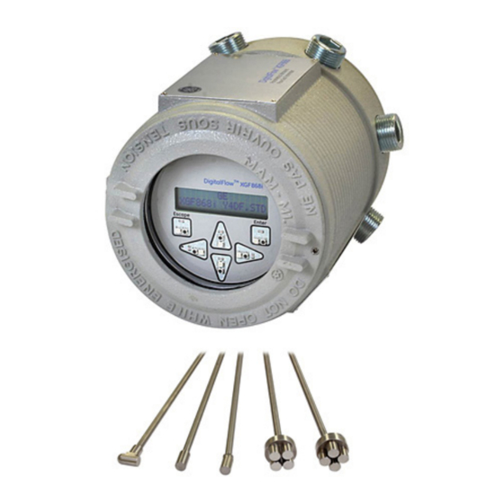
DigitalFlow™ XGF868i
Panametrics flare gas
flow transmitter
Programming manual
Related Manuals for Baker Hughes Panametrics DigitalFlow XGF868i
Summary of Contents for Baker Hughes Panametrics DigitalFlow XGF868i
-
Page 1
DigitalFlow™ XGF868i Panametrics flare gas flow transmitter Programming manual… -
Page 3
DigitalFlow™ XGF868i Panametrics flare gas flow transmitter Programming manual 910-198P Rev. C February 2015… -
Page 4
[no content intended for this page]… -
Page 5
Information paragraphs Safety issues Note: These paragraphs provide information that provides a WARNING! deeper understanding of the situation, but is not essential to It is the responsibility of the user to make sure the proper completion of the instructions. all local, county, state and national codes, regulations, rules and laws related to safety IMPORTANT: and safe operating conditions are met for… -
Page 6
Environmental compliance Waste Electrical and Electronic Equipment (WEEE) directive Panametrics is an active participant in Europe’s Waste Electrical and Electronic Equipment (WEEE) take-back initiative, directive 2012/19/EU. The equipment that you bought has required the extraction and use of natural resources for its production. It may contain hazardous substances that could impact health and the environment. -
Page 7: Table Of Contents
Contents Chapter 1. Programming site data …………1 Introduction .
-
Page 8
Chapter 3. Logging data …………. . . 29 Introduction . -
Page 9
C.6 Entering data in the global menu …………. . . 64 C.6.1 Entering global-system data . -
Page 11: Chapter 1. Programming Site Data
Chapter 1. Programming site data Introduction Programming methods The XGF868i flow transmitter must be properly installed You can program the XGF868i via either the keypad on the and programmed, as described in the Startup guide, lower part of the glass window, or PanaView™, a PC-based, before it can provide accurate flow rate measurements.
-
Page 12: The Xgf868I Keypad
The XGF868i keypad Keypad program Along with the 2-line, 16-character LCD, the XGF868i Six keys on the keypad enable users to program includes a 6-key magnetic keypad. The decal cutout for the XGF868i: each key contains a hall effect sensor, pushbutton switch •…
-
Page 13: Activating A Channel
Activating a channel Entering system data for the channel The channelx-ACTIV submenu permits selection of the desired measurement method. In addition, it is used The channelx-system submenu is used to enter to activate/deactivate one or both of the channels in a system parameters for the channel.
-
Page 14: Selecting Totalizer Units
1.5.3 Selecting totalizer units 1.5.4 Selecting mass flow units 1. Scroll to the desired totalizer units for a totalized 1. Scroll to the desired mass flow units for the flow rate flow rate display and press [enter]. Table 1 on page 3 display and press [enter].
-
Page 15: Entering Transducer And Pipe Parameters
Entering transducer and pipe parameters 1.6.2 Pipe data Enter the transducer and pipe parameters via the pipe submenu. While following the programming instructions, If either a standard or a special transducer is being used, refer to Figure 28 on page 40. the programming sequence should be rejoined at this point.
-
Page 16
1.6.2a Path and axial lengths Procedure options 7. To enter the path length: After entering the calibration factor, the XGF868i returns to a. Use the [] arrow key to highlight the path length the channel program. Do one of the following: unit type at the right of the screen. -
Page 17: Entering Zero Cutoff And Setting Up Inputs
Entering zero cutoff and setting up inputs Enter the zero cutoff value and set up the temperature and actual temperature is used to calculate the pressure inputs via the I/O submenu. While programming standard mass flow rate. these parameters, refer to Figure 28 on page 40. 2.
-
Page 18: Entering Setup Data
Entering setup data The signal limits, response times, mass flow and multiple CAUTION! K factors for the XGF868i are specified via the setup The signal default settings are suitable for submenu. The following four submenus are included most applications. Consult with Panametrics in this section: before changing any of these parameters.
-
Page 19
Table 4: Transducer signal settings Transducer signal Default Range Description parameters value The E6: CYCLE SKIP error message appears when the calculated fluid 0 to 250 ft/s 15 ft/s velocity changes by more than the programmed ACCELERATION LIMIT Acceleration limit (0 to 76 m/s) (5 m/s) value from one reading to the next. -
Page 20: Initializing Setup Parameters — Default Setup
1.8.2 Initializing setup parameters — 1.8.3 Setting response time — V averaging default setup Use this option to specify the number of readings that occur before the meter will respond to a step change in Use this option to initialize (reset) all of the parameters flow rate.
-
Page 21: Using Advanced Features
1.8.4 Using advanced features 1.8.4c Activating mass flow This option enables you to access the more advanced features of the meter. In this option you can do the following: Use this option to calculate mass flow from a static • Enter a table of K factors — to compensate for non-linear fluid density.
-
Page 22: Entering Global Data
Entering global data 1.9.1a Selecting volumetric units The global menu is used to enter information that is not specific to either of the individual channels. Information 1. Scroll to the desired volumetric units for the flow rate programmed via this menu is used to compute parameters display and press [enter].
-
Page 23: Setting Up Inputs And Outputs
1.9.1c Selecting mass flow units 1.9.2 Setting up inputs and outputs 1. Scroll to the desired mass flow units for the flow rate Set up the XGF868i inputs and outputs via the I/O submenu. display and press [enter]. The available units for this While following the programming instructions, refer to Figure prompt are determined by the selection made at 30 on page 42 and Figure 31 on page…
-
Page 24
Procedure options Table 7: Error response options After completing the above steps, the XGF868i returns to the global I/O window. Do one of the following: Option Output response Totalizer response • To continue programming, refer to Appendix A. Menu Maps on page 39, to navigate to the desired menu. Continues to totalize, Holds the last HOLD… -
Page 25
Table 9: Available measurement parameters Option bar Description Good Displays the flow velocity. N.A. N.A. VOLUM Displays the volumetric flow. N.A. N.A. +TOTL Displays the forward totalized volume flow. N.A. N.A. -TOTL Displays the reverse totalized volume flow. N.A. N.A. TIME Displays the total flow measurement time. -
Page 26
Table 9: Available measurement parameters Option bar Description Good PRESR Displays the gas pressure (from 0/4-20 mA input). N.A. N.A. Displays the molecular weight. N.A. N.A. Displays the compressibility. N.A. N.A. AcVOL Displays actual volumetric flow. N.A. N.A. StVOL Displays standard volumetric flow. N.A. -
Page 27
5. Use the arrow keys to enter a value (a temperature 1.9.2f Frequency outputs value for special inputs) for the low end of the analog The frequency output issues a continuous signal with a input range and press [enter]. frequency proportional to the selected measurement. 6. -
Page 28: Configuring The Communications Port
1.9.3 Configuring the communications port 1.9.3b Setting up MODBUS communications The XGF868i flowmeter is equipped with an RS232 serial interface. The meter can be configured with a When equipped with an optional MODBUS output card, the MODBUS option card for MODBUS communications, a XGF868i can transmit flow data serially to a flow computer, Foundation Fieldbus option card for Foundation Fieldbus or SCADA, using a Gould-type RTU protocol.
-
Page 29: Requesting Parameters Using Modbus
1.9.4 Requesting parameters using MODBUS To request specific parameters from the XGF868i via the MODBUS, the control system must enter the appropriate register number. Only registers 1 through 90 are available for MODBUS communications, while registers 508 through 512 are used by the XGF868i to store the MODBUS parameters.
-
Page 30
Table 10: MODBUS registers for a 2-channel XGF868i MODBUS DPR hex Scaling Description Size in bytes Reg # addr (decimal places) Ch2 std volumetric #Q DIGITS 4 (IEEE 32 bit) Ch2 fwd totals #T DIGITS 4 (2 16 bit int) Ch2 rev totals #T DIGITS 4 (2 16 bit int) -
Page 31
Table 10: MODBUS registers for a 2-channel XGF868i MODBUS DPR hex Scaling Description Size in bytes Reg # addr (decimal places) Avg rev mass totals #MT DIGITS 4 (2 16-bit int) Avg #mass tot digits Avg timer 4 (2 16-bit int) 5Avg error code Avg sound speed 4 (2 16-bit int) -
Page 32: Exiting The User Program
1.9.5 Activating security 1.10 Exiting the user program In order to prevent unauthorized tampering with the After completing the COMM option, the XGF868i returns to flowmeter’s programming, the XGF868i is equipped with the global program prompt. press [escape] twice to return a security feature that locks all the keys except [prog] to the keypad program, and a third time to return to the meter display.
-
Page 33: Chapter 2. Displaying Data
Chapter 2. Displaying data Introduction The OFF setting switches the measurement display off, while the KEY setting enables users to change the measurement display via the arrow keys, without accessing the keypad This chapter explains how to display measurement data program.
-
Page 34: Displaying Data On A Computer Terminal
2.3 Displaying data on a computer terminal The flow rate data collected by the XGF868i may be displayed in various formats on a remote computer terminal via the meter’s RS232 serial port. This requires the use of the optional PanaView software. Refer to the instructions below to display data via PanaView.
-
Page 35: Graphing The Output
6. If the [continuous] option was selected in step 5 above, 2.3.3 Graphing the output click on the [stop] option button, which has replaced To collect data from the instrument and display it the original [continuous] option button, to terminate graphically in a new format, complete the following steps: data collection.
-
Page 36: Displaying Transducer Signals
2.3.2b Graphing data 2.3.3 Displaying transducer signals The PanaView network tree has already been described, and Along with flow rate data, PanaView enables XGF868i users the display pane shows only a graph in the default style with to read and plot transducer signals from the XGF868i. no data points.
-
Page 37
2.3.3a Reading transducer signals 2.3.3b Plotting transducer signals 3. To read a signal from the meter, click on the [read To plot the selected signal, click on [plot]. A graphical signals] button. (If the meter is a multi-channel window opens, as shown in Figure 8 below. instrument, open the channel drop-down menu and click on the desired channel.) After a moment, the properties window appears similar to Figure 7 below. -
Page 39: Chapter 3. Logging Data
Chapter 3. Logging data Introduction PanaView can create PC log files for the XGF868i for storage on the PC’s hard drive. This chapter explains how to use the XGF868i data logging capability with PanaView. 3.2 Logging with PanaView PanaView is capable of creating and viewing log files of the following types: •…
-
Page 40: Creating Meter Logs
3.3 Creating meter logs To create a new meter log, complete the following steps: d. Type the desired log message in the right window, and click [next item]. 1. From the new meter browser in PanaView, expand the network tree and open the edit functions option e.
-
Page 41: Creating An Error Log
each parameter, type the desired number in the • If you select edit, PanaView asks first for the desired right window, (or scroll to and click on the desired year, then for the month, and finally for the day. For month) and click [next item] (or simply click [next each parameter, type the desired number in the item] to step through the parameters).
-
Page 42: Creating Pc Logs
3.4 Creating PC logs PC logs are created in a different menu from the meter logs 3. Double click on PC logs to advance to the dialog box described in the last section. To create a new PC log: shown in Figure 16. below. 1.
-
Page 43: Viewing Meter Log Files
NOTE: Start time and stop time cannot be specified NOTE: To add all the channel parameters to a given log, for PC logs. These options are inactive in the right-click on the desired channel. A pop-up button, PC log window. “add group to log,”…
-
Page 44: Viewing Pc Log Files
3.6 Viewing PC log files After one or more PC log files have been created, the logs You can monitor the progress of an ongoing log in several may be viewed by using PanaView as follows: ways: 1. You can access PC logs in two ways: •…
-
Page 45: Chapter 4. Printing Data
Chapter 4. Printing data Data types for printing The XGF868i flowmeter has no ability to print any of its data directly. However, any of the data stored in its memory may be printed via the built-in RS232 communications port, using a computer terminal. In order to use the capability, the XGF868i must be linked to the computer terminal with the optional PanaView software.
-
Page 46
[no content intended for this page]… -
Page 47: Chapter 5. Clearing Data
Chapter 5. Clearing data Introduction This chapter explains how to purge totalized measurements, site data and/or log files from the XGF868i memory. NOTE: For detailed information on creating a log file, see Chapter 3. Logging data on page 29. For detailed information on programming site data, see Chapter 1.
-
Page 48: Clearing The Xgf868I Memory
5.2 Clearing the XGF868i memory If the XGF868i available memory becomes nearly full, it may be necessary to purge some or all of the existing data from memory, before any additional data can be stored. In order to accomplish this task, proceed to the appropriate section for step-by-step instructions.
-
Page 49: Appendix A. Menu Maps
Appendix A. Menu maps The following Menu Maps are included in this appendix: • Figure 28 on page 40, “PROG > CHx > ACTIV, SYSTM, PIPE & I/O Menus” • Figure 29 on page 41, “PROG > CHx > SETUP Menu” •…
-
Page 50
Figure 28: PROG > CHx > ACTIV, SYSTM, PIPE and I/O menus… -
Page 51
Figure 29: PROG > CHx > SETUP menu… -
Page 52
Figure 30: PROG > GLOBL > SYSTM, I/O and COMM menus… -
Page 53
Figure 31: PROG > GLOBL > I/O > OPTIONS menu… -
Page 55: Appendix B. Data Records
Appendix B. Data records Available option cards The XGF868i can hold one option card in slot 1 and one in slot 2. The available configurations are listed in Table 12 below. Table 12: Option card configurations Card # Slot # Configuration 1473-02 OI — 2 current inputs…
-
Page 56: Setup Data
B.3 Setup data After the XGF868i flow transmitter has been installed, setup data must be entered via the user program prior to operation. record that information in Table 14 below. Table 14: Setup data General information Model # Serial # Software version Setup date Channel — status…
-
Page 57
Table 14: Setup data Channel — pipe parameters Channel 1 Channel 2 Transducer type SPEC Transducer type Transducer # Transducer # Spec. trans. freq. Spec. trans. freq. Spec. trans. Tw Spec. trans. Tw Pipe O.D. Pipe O.D. Pipe wall Pipe wall Path length (P) Path length (P) Axial length (L) -
Page 58
Table 14: Setup data Channel — SETUP — advanced features — multi K factors K-factor # Velocity K-factor K-factor # Velocity K-factor… -
Page 59
Table 14: Setup data Channel — SETUP — advanced features — mass flow calculation Mass flow Mass flow Density type Fluid dens. Mol. wt. Density type Fluid dens. Mol. wt. or Q Actual Standard or Q Actual Standard Fluid density Fluid density Mole. -
Page 61: Appendix C. Programming The Xgf868I With Panaview
Appendix C. Programming the XGF868i with PanaView™ C.1 Introduction The XGF868i flow transmitter must be properly installed and programmed, as described in the Startup guide, before it can provide accurate flow rate measurements. After completing the installation and initial setup, use this chapter to program the advanced features of the model XGF868i’s via the PanaView™…
-
Page 62: Programming With Panaview
C.2 Programming with PanaView™ You can program the XGF868i with PanaView™, a Panametrics PC-based, non-resident software program that communicates with the XGF868i via its RS232 serial port. C.2.1 Preparing for PanaView programming Before you attempt to communicate with the XGF868i, be sure you have linked your PC to the XGF868i via an RS232 interface.
-
Page 63: Setting Up Ethernet Communications
C.2.3 Setting up Ethernet communications C.2.4 Modifying Ethernet parameters If you have selected TCP/IP in step 6 on the previous page, To establish Ethernet communications with the XGF868i the setup communications window appears similar to or to modify its IP parameters, you will need to install the Figure 34 below.
-
Page 64: Adding The Xgf868I
C.3 Adding the XGF868i To add the XGF868i on the IDM-configured communications If the initialization is successful, the meter browser shows a port, complete the following steps: listing similar to Figure 37 below. 1. Highlight the communication port to which the meter will be added by clicking on it, and then open the edit menu on the menu bar (if the communication port is not highlighted first, the new meter option is not…
-
Page 65: Entering The User Program Using Panaview
C.4 Entering the user program using PanaView NOTE: Be sure to record all the programming data entered in this chapter in Appendix B. Data records on page 45. Programming of the status, system, and pipe submenus of the channel menu and the global-system menu are required for basic operation of the XGF868i.
-
Page 66
Figure 43: Site edit menu with current Settings Figure 42: Pipe parameters option in the site edit menu 6. When you have completed entering parameters in c. Do one of the following: a given option, click [exit page] to close the option. Click on [next item] to proceed to the next menu item, You can then double-click on another option, or click [close] to close the window. -
Page 67: Entering Data In The Channel Menu
C.5 Entering data in the channel menu C.5.2 Entering data in the channel system The channel menu is used to enter data specific to each channel. Refer to Figures D-1 through D-3 in Appendix option D. PanaView menu maps for the XGF868i on page 79, and 1.
-
Page 68: Entering Pipe Parameters
C.5.2a Programming the mass flow option C.5.3 Entering pipe parameters 1. Double-click on the desired mass flow units for flow rate Enter the transducer and pipe parameters via the pipe display (listed in Table 16 below). submenu. While following the programming instructions, see Figure 55 on page 80 of Appendix D, PanaView menu maps.
-
Page 69
C.5.3b Pipe OD C.5.3c Path and axial lengths 4. Click on the appropriate pipe OD unit type in the 6. Click on the appropriate path length unit type in the center pane from the list shown in Table 17 below. center pane. -
Page 70: Entering Input/Output Parameters
C.5.4 Entering input/output parameters C.5.4c Base temperature Enter the zero cutoff value and set up the temperature, pressure and quality inputs via the input/output submenu. 1. Enter the base temperature and click [next item]. While programming these parameters, refer to Figure 55 on The ratio of this value to the actual temperature is page 80 of Appendix D, PanaView menu maps.
-
Page 71: Entering Setup Parameters
C.5.5 Entering setup parameters C.5.5a The signal option Use this option to set the limits for the incoming signal The signal limits and response times for the XGF868i are and other parameters affecting the transducer signal. For specified via the SETUP submenu. While following the example, the programmed signal strength low limit may programming instructions, refer to Figure 57 on page be used to determine the trigger point for an alarm.
-
Page 72
Table 18: Transducer signal settings Transducer signal Default Range Description parameters value The amplitude discriminator measures the transducer signal received by the model XGF868i. The default value for the above parameter is 14, and values from 0 to 100 are acceptable. The Amplitude 0 to 100 E5: AMPLITUDE error message appears when the amplitude… -
Page 73
C.5.5b The default setup option 4. Double-click on yes to edit the K-factor table or on no to retain the current K-factor table (and return to Use this option to initialize (reset) all of the parameters the advanced features window). within the set up signal menu back to their default values. -
Page 74: Entering Data In The Global Menu
C.6 Entering data in the global menu C.6.1a Volumetric units The global menu is used to enter information that is not specific to any of the individual channels. Information 1. Double-click on the desired volumetric units for the flow programmed via this menu is used to enter several general rate display.
-
Page 75: Setting Up Inputs And Outputs
C.6.1c Programming mass flow data C.6.2 Setting up inputs and outputs 1. Double-click on the desired mass flow units for flow rate Set up the XGF868i inputs and outputs via the I/O submenu. display. The options are listed in Table 20 below. While following the programming instructions, see Figure 58 on page 83 in Appendix D, PanaView menu maps.
-
Page 76
Table 21: Error options and responses for a one-channel meter Option Output response Totalizer response Hold last value Holds the last “good” reading Holds the last “good” reading and continues to totalize, based on that reading Force low Forces the outputs to the low set point Stops totalizing Force high Forces the outputs to the high set point… -
Page 77
C.6.2c Setting up option cards The XGF868i has two built-in analog outputs, which are Table 24: Channel options assigned to slot 0. Also, a variety of input/output option cards may be installed in slot 1. See Chapter 1, Installation, Option Description of the Startup Guide for a complete description of the available option cards. -
Page 78
Table 25: Available measurement parameters Option bar Description Good Velocity Displays the flow velocity. N.A. N.A. Volumetric Displays the volumetric flow. N.A. N.A. FWD total Displays the forward totalized volume flow. N.A. N.A. REV total Displays the reverse totalized volume flow. N.A. -
Page 79
Table 25: Available measurement parameters Option bar Description Good DN +- peak Displays signal peaks for the downstream transducer. 100-2300 <100 or >2300 Temperature Displays the gas temperature (from 0/4-20 mA input). N.A. N.A. Pressure Displays the gas pressure (from 0/4-20 mA input). N.A. -
Page 80
7. Enter the units of measurement for input A and click 6. Enter a flow rate value for the full (high) end of the [next item]. frequency output range and click [next item]. 8. Enter a temperature value for the base (low) end 7. -
Page 81: Entering Communications Data
C.6.3 Entering communications data The XGF868i flowmeter is equipped with an RS232 serial NOTE: The XGF868i MODBUS communication settings interface. The serial port is used to transmit stored data and chosen in the next four steps must match those of the displayed readings to a personal computer by connecting MODBUS control system.
-
Page 82
Table 27: MODBUS registers MODBUS DPR hex MODBUS Description Scaling (decimal places) Size in bytes reg # addr reg # Ch1 rev totals #T DIGITS 4 (2 16 bit int) Ch1 #tot digits Ch1 mass flow #M DIGITS 4 (IEEE 32 bit) Ch1 Fwd mass totals #MT DIGITS 4 (2 16-bit int) -
Page 83
Table 27: MODBUS registers MODBUS DPR hex MODBUS Description Scaling (decimal places) Size in bytes reg # addr reg # Ch2 Fwd mass totals #MT DIGITS 4 (2 16-bit int) Ch2 rev mass totals #MT DIGITS 4 (2 16-bit int) Ch2 #mass tot digits Ch2 timer 4 (2 16-bit int) -
Page 84
Table 27: MODBUS registers MODBUS DPR hex MODBUS Description Scaling (decimal places) Size in bytes reg # addr reg # Avg timer 4 (2 16-bit int) 5Avg error code Avg sound s speed 4 (2 16-bit int) 2MODBUS baud rate Notes: 1. -
Page 85: Exiting The Site Edit Menu
C.7 Exiting the site edit menu After leaving the global submenu, PanaView returns to the site edit menu. Click [close] to exit the site edit menu. Then proceed to Chapter 3, Operation, of the Startup guide for instructions on taking measurements, or refer to the appropriate chapters of this manual for detailed instructions on using the other features of the XGF868i flow transmitter.
-
Page 86: Saving Site Data
C.9 Saving site data The XGF868i holds setup parameters for a single internal site, called Working. Through PanaView, users can store site file data in a PC and reload it into the XGF868i. To save or reload site data via PanaView: 1.
-
Page 87: Saving New Site Data To The Xgf868I
C.9.2 Saving new site data to the XGF868i C.9.4 Clearing a site from the meter To save new site data to the meter: As the XGF868i has only one site loaded (working) at any time, it is not possible to remove this site. To change site 1.
-
Page 89: Appendix D. Panaview Menu Maps For The Xgf868I
Appendix D. PanaView menu maps for the XGF868i The following PanaView menu maps are included in this appendix: • Figure 55 on page 80, “PanaView prog > CHx > ACTIV, SYSTM, PIPE & I/O menus • Figure 56 on page 81, “PanaView prog > CHx > SETUP menu,”…
-
Page 90
Figure 55: PanaView PROG > CHx > ACTIV, SYSTM, PIPE and I/O menus… -
Page 91
Figure 56: PanaView PROG > CHx > SETUP menu… -
Page 92
Figure 57: PanaView PROG > GLOBL > SYSTM, I/O and COMM menus… -
Page 93
Figure 58: PanaView PROG > GLOBL > I/O > OPTIONS menu… -
Page 95: Appendix E. Foundation Fieldbus Communications
Appendix E. Foundation fieldbus communications Introduction Foundation fieldbus provides a means of communicating with the flowmeter. The patent numbers which apply are 5,909,363 and 6,424,872. This foundation fieldbus device supports six analog input (AI) blocks, which can be configured to supply the network measurements shown in Table 28 below.
-
Page 96: Configuration Utility Setup
E.2 Configuration utility setup E.3 Selecting the desired measurements The following is an example setup using National Instruments Configuration Utility v3.1. To set the measurement unit for each AI: Figure 59 below shows the configuration utility with a 1. Double click on the FLOW transducer block (in the tree flowmeter on the network (Panametrics flow-XGF).
-
Page 97: Selecting Units For Ai Blocks
E.4 Selecting units for AI blocks E.5 Resetting instrument totalizers To select the units for the individual AI blocks: To reset the instrument totalizers: 1. Double click on the AI block for which you wish to set 1. Double click on the FLOW transducer block (in the the units (ANALOG_INPUT_1 or ANALOG_INPUT_2 in the tree under GEFlow-XGF;…
-
Page 98: Function Block Application
E.6 Function block application Figure 63 below is an example setup using the function block application editor. The flowmeter AI blocks, along with the AO and PID of another device on the network, are displayed. We have connected the AI_1 OUT of the flowmeter to the CAS IN of the AO block.
-
Page 99
Warranty Return policy Each instrument manufactured by Panametrics is If a Panametrics instrument malfunctions within the warranted to be free from defects in material and warranty period, the following procedure must be workmanship. Liability under this warranty is limited to completed: restoring the instrument to normal operation or replacing 1. -
Page 100
Tel: +1 800 833 9438 (toll-free) E-mail: mstechsupport@bakerhughes.com Tel: +1 978 437 1000 E-mail: mstechsupport@bakerhughes.com Panametrics, a Baker Hughes Business, provides solutions in the toughest applications and environments for moisture, oxygen, liquid and gas flow measurement. Experts in flare management, Panametrics technology also reduces flare emissions and optimizes performance.
![]()
|
GE |
|
|
Measurement & Control |
Flow |
DigitalFlow™ XGF868i
Panametrics Flare Gas Flow Transmitter
Programming Manual
910-198P Rev. C
February 2015

DigitalFlow™ XGF868i
Panametrics Flare Gas Flow Transmitter
Programming Manual
910-198P Rev. C
February 2015
www.ge-mcs.com
©2015 General Electric Company. All rights reserved. Technical content subject to change without notice.
[no content intended for this page]
ii
Preface
Information Paragraphs
Note: These paragraphs provide information that provides a deeper understanding of the situation, but is not essential to the proper completion of the instructions.
IMPORTANT: These paragraphs provide information emphasizing instructions which are essential to proper setup of the equipment. Failure to follow these instructions carefully may cause unreliable performance.
WARNING! Indicates a potentially hazardous situation which can result in serious personal injury or death, if it is not avoided.
CAUTION! Indicates a potentially hazardous situation which can result in minor or moderate injury to personnel or damage to the equipment, if it is not avoided.
HIGH VOLTAGE! This symbol indicates the presence of high voltage. It calls your attention to situations or operations that could be dangerous to you and other persons operating the equipment. Read these messages and follow the instructions carefully.
Safety Issues
WARNING! It is the responsibility of the user to make sure all local, county, state and national codes, regulations, rules and laws related to safety and safe operating conditions are met for each installation.
Auxiliary Equipment
Local Safety Standards
The user must make sure that he operates all auxiliary equipment in accordance with local codes, standards, regulations, or laws applicable to safety.
Working Area
WARNING! Auxiliary equipment may have both manual and automatic modes of operation. As equipment can move suddenly and without warning, do not enter the work cell of this equipment during automatic operation, and do not enter the work envelope of this equipment during manual operation. If you do, serious injury can result.
WARNING! Make sure that power to the auxiliary equipment is turned OFF and locked out before you perform maintenance procedures on the equipment.
|
DigitalFlow™ XGF868i Programming Manual |
iii |

Preface
Qualification of Personnel
Make sure that all personnel have manufacturer-approved training applicable to the auxiliary equipment.
Personal Safety Equipment
Make sure that operators and maintenance personnel have all safety equipment applicable to the auxiliary equipment. Examples include safety glasses, protective headgear, safety shoes, etc.
Unauthorized Operation
Make sure that unauthorized personnel cannot gain access to the operation of the equipment.
Environmental Compliance
Waste Electrical and Electronic Equipment (WEEE) Directive
GE Measurement & Control Solutions is an active participant in Europe’s Waste Electrical and Electronic Equipment (WEEE) take-back initiative, directive 2012/19/EU.
The equipment that you bought has required the extraction and use of natural resources for its production. It may contain hazardous substances that could impact health and the environment.
In order to avoid the dissemination of those substances in our environment and to diminish the pressure on the natural resources, we encourage you to use the appropriate take-back systems. Those systems will reuse or recycle most of the materials of your end life equipment in a sound way.
The crossed-out wheeled bin symbol invites you to use those systems.
If you need more information on the collection, reuse and recycling systems, please contact your local or regional waste administration.
Visit http://www.ge-mcs.com/en/about-us/environmental-health-and-safety/weee.html for take-back instructions and more information about this initiative.
|
iv |
DigitalFlow™ XGF868i Programming Manual |

Contents
Chapter 1. Programming Site Data
1.1 Introduction . . . . . . . . . . . . . . . . . . . . . . . . . . . . . . . . . . . . . . . . . . . . . . . . . . . . . . . . . . . . . . . . . . . . . . . . . . . . . . . . . . . . . . . . . . . .1 1.2 Programming Methods . . . . . . . . . . . . . . . . . . . . . . . . . . . . . . . . . . . . . . . . . . . . . . . . . . . . . . . . . . . . . . . . . . . . . . . . . . . . . . . . .2 1.3 The XGF868i Keypad. . . . . . . . . . . . . . . . . . . . . . . . . . . . . . . . . . . . . . . . . . . . . . . . . . . . . . . . . . . . . . . . . . . . . . . . . . . . . . . . . . . .3 1.4 Activating a Channel. . . . . . . . . . . . . . . . . . . . . . . . . . . . . . . . . . . . . . . . . . . . . . . . . . . . . . . . . . . . . . . . . . . . . . . . . . . . . . . . . . . .5 1.5 Entering System Data for the Channel . . . . . . . . . . . . . . . . . . . . . . . . . . . . . . . . . . . . . . . . . . . . . . . . . . . . . . . . . . . . . . . . . . .6
1.5.1 Accessing the Channelx-System Submenu . . . . . . . . . . . . . . . . . . . . . . . . . . . . . . . . . . . . . . . . . . . . . . . . . . . . . . . . .6 1.5.2 Selecting Volumetric Units . . . . . . . . . . . . . . . . . . . . . . . . . . . . . . . . . . . . . . . . . . . . . . . . . . . . . . . . . . . . . . . . . . . . . . . . .6 1.5.3 Selecting Totalizer Units . . . . . . . . . . . . . . . . . . . . . . . . . . . . . . . . . . . . . . . . . . . . . . . . . . . . . . . . . . . . . . . . . . . . . . . . . . .6 1.5.4 Selecting Mass Flow Units . . . . . . . . . . . . . . . . . . . . . . . . . . . . . . . . . . . . . . . . . . . . . . . . . . . . . . . . . . . . . . . . . . . . . . . . .7 1.6 Entering Transducer and Pipe Parameters . . . . . . . . . . . . . . . . . . . . . . . . . . . . . . . . . . . . . . . . . . . . . . . . . . . . . . . . . . . . . . .8 1.6.1 Special Transducers . . . . . . . . . . . . . . . . . . . . . . . . . . . . . . . . . . . . . . . . . . . . . . . . . . . . . . . . . . . . . . . . . . . . . . . . . . . . . . .8 1.6.2 Pipe Data . . . . . . . . . . . . . . . . . . . . . . . . . . . . . . . . . . . . . . . . . . . . . . . . . . . . . . . . . . . . . . . . . . . . . . . . . . . . . . . . . . . . . . . . .9
1.7 Entering Zero Cutoff and Setting Up Inputs . . . . . . . . . . . . . . . . . . . . . . . . . . . . . . . . . . . . . . . . . . . . . . . . . . . . . . . . . . . . 11 1.7.1 Zero Cutoff Value. . . . . . . . . . . . . . . . . . . . . . . . . . . . . . . . . . . . . . . . . . . . . . . . . . . . . . . . . . . . . . . . . . . . . . . . . . . . . . . . 11 1.7.2 Temperature Input . . . . . . . . . . . . . . . . . . . . . . . . . . . . . . . . . . . . . . . . . . . . . . . . . . . . . . . . . . . . . . . . . . . . . . . . . . . . . . 11 1.7.3 Base Temperature. . . . . . . . . . . . . . . . . . . . . . . . . . . . . . . . . . . . . . . . . . . . . . . . . . . . . . . . . . . . . . . . . . . . . . . . . . . . . . . 12 1.7.4 Pressure Input. . . . . . . . . . . . . . . . . . . . . . . . . . . . . . . . . . . . . . . . . . . . . . . . . . . . . . . . . . . . . . . . . . . . . . . . . . . . . . . . . . . 12 1.7.5 Base Pressure . . . . . . . . . . . . . . . . . . . . . . . . . . . . . . . . . . . . . . . . . . . . . . . . . . . . . . . . . . . . . . . . . . . . . . . . . . . . . . . . . . . 12 1.7.6 Low Pressure Switch. . . . . . . . . . . . . . . . . . . . . . . . . . . . . . . . . . . . . . . . . . . . . . . . . . . . . . . . . . . . . . . . . . . . . . . . . . . . . 13
1.8 Entering Setup Data . . . . . . . . . . . . . . . . . . . . . . . . . . . . . . . . . . . . . . . . . . . . . . . . . . . . . . . . . . . . . . . . . . . . . . . . . . . . . . . . . . 14 1.8.1 Setting Transducer Signal Parameters. . . . . . . . . . . . . . . . . . . . . . . . . . . . . . . . . . . . . . . . . . . . . . . . . . . . . . . . . . . . 14 1.8.2 Initializing Setup Parameters — Default Setup . . . . . . . . . . . . . . . . . . . . . . . . . . . . . . . . . . . . . . . . . . . . . . . . . . . . . 17 1.8.3 Setting Response Time — V Averaging . . . . . . . . . . . . . . . . . . . . . . . . . . . . . . . . . . . . . . . . . . . . . . . . . . . . . . . . . . . . . 17 1.8.4 Using Advanced Features. . . . . . . . . . . . . . . . . . . . . . . . . . . . . . . . . . . . . . . . . . . . . . . . . . . . . . . . . . . . . . . . . . . . . . . . 18
1.9 Entering Global Data . . . . . . . . . . . . . . . . . . . . . . . . . . . . . . . . . . . . . . . . . . . . . . . . . . . . . . . . . . . . . . . . . . . . . . . . . . . . . . . . . 20 1.9.1 Entering Global System Data. . . . . . . . . . . . . . . . . . . . . . . . . . . . . . . . . . . . . . . . . . . . . . . . . . . . . . . . . . . . . . . . . . . . . 21 1.9.2 Setting Up Inputs and Outputs . . . . . . . . . . . . . . . . . . . . . . . . . . . . . . . . . . . . . . . . . . . . . . . . . . . . . . . . . . . . . . . . . . . 23 1.9.3 Configuring the Communications Port. . . . . . . . . . . . . . . . . . . . . . . . . . . . . . . . . . . . . . . . . . . . . . . . . . . . . . . . . . . . 32 1.9.4 Requesting Parameters Using MODBUS . . . . . . . . . . . . . . . . . . . . . . . . . . . . . . . . . . . . . . . . . . . . . . . . . . . . . . . . . . 34 1.9.5 Activating Security . . . . . . . . . . . . . . . . . . . . . . . . . . . . . . . . . . . . . . . . . . . . . . . . . . . . . . . . . . . . . . . . . . . . . . . . . . . . . . 37
1.10 Exiting the User Program . . . . . . . . . . . . . . . . . . . . . . . . . . . . . . . . . . . . . . . . . . . . . . . . . . . . . . . . . . . . . . . . . . . . . . . . . . . . . 37
Chapter 2. Displaying Data
2.1 Introduction . . . . . . . . . . . . . . . . . . . . . . . . . . . . . . . . . . . . . . . . . . . . . . . . . . . . . . . . . . . . . . . . . . . . . . . . . . . . . . . . . . . . . . . . . . 39 2.2 Displaying Data with the LCD . . . . . . . . . . . . . . . . . . . . . . . . . . . . . . . . . . . . . . . . . . . . . . . . . . . . . . . . . . . . . . . . . . . . . . . . . 39 2.2.1 Adjusting LCD Contrast . . . . . . . . . . . . . . . . . . . . . . . . . . . . . . . . . . . . . . . . . . . . . . . . . . . . . . . . . . . . . . . . . . . . . . . . . . 39 2.2.2 Programming the LCD . . . . . . . . . . . . . . . . . . . . . . . . . . . . . . . . . . . . . . . . . . . . . . . . . . . . . . . . . . . . . . . . . . . . . . . . . . . 40 2.3 Displaying Data on a Computer Terminal . . . . . . . . . . . . . . . . . . . . . . . . . . . . . . . . . . . . . . . . . . . . . . . . . . . . . . . . . . . . . . 42 2.3.1 Preparing for PanaView Programming. . . . . . . . . . . . . . . . . . . . . . . . . . . . . . . . . . . . . . . . . . . . . . . . . . . . . . . . . . . . 42 2.3.1 The Text Display Output . . . . . . . . . . . . . . . . . . . . . . . . . . . . . . . . . . . . . . . . . . . . . . . . . . . . . . . . . . . . . . . . . . . . . . . . . 43 2.3.2 Graphing the Output . . . . . . . . . . . . . . . . . . . . . . . . . . . . . . . . . . . . . . . . . . . . . . . . . . . . . . . . . . . . . . . . . . . . . . . . . . . . 46 2.3.3 Displaying Transducer Signals . . . . . . . . . . . . . . . . . . . . . . . . . . . . . . . . . . . . . . . . . . . . . . . . . . . . . . . . . . . . . . . . . . . 48
|
DigitalFlow™ XGF868i Programming Manual |
v |

Contents
Chapter 3. Logging Data
3.1 Introduction. . . . . . . . . . . . . . . . . . . . . . . . . . . . . . . . . . . . . . . . . . . . . . . . . . . . . . . . . . . . . . . . . . . . . . . . . . . . . . . . . . . . . . . . . . .51 3.2 Logging with PanaView. . . . . . . . . . . . . . . . . . . . . . . . . . . . . . . . . . . . . . . . . . . . . . . . . . . . . . . . . . . . . . . . . . . . . . . . . . . . . . . .51 3.3 Creating Meter Logs . . . . . . . . . . . . . . . . . . . . . . . . . . . . . . . . . . . . . . . . . . . . . . . . . . . . . . . . . . . . . . . . . . . . . . . . . . . . . . . . . . .52 3.3.1 Creating a Standard Meter Log . . . . . . . . . . . . . . . . . . . . . . . . . . . . . . . . . . . . . . . . . . . . . . . . . . . . . . . . . . . . . . . . . . .53 3.3.2 Creating an Error Log. . . . . . . . . . . . . . . . . . . . . . . . . . . . . . . . . . . . . . . . . . . . . . . . . . . . . . . . . . . . . . . . . . . . . . . . . . . . .55 3.4 Creating PC Logs . . . . . . . . . . . . . . . . . . . . . . . . . . . . . . . . . . . . . . . . . . . . . . . . . . . . . . . . . . . . . . . . . . . . . . . . . . . . . . . . . . . . . .57
3.5 Viewing Meter Log Files. . . . . . . . . . . . . . . . . . . . . . . . . . . . . . . . . . . . . . . . . . . . . . . . . . . . . . . . . . . . . . . . . . . . . . . . . . . . . . . .60 3.6 Viewing PC Log Files. . . . . . . . . . . . . . . . . . . . . . . . . . . . . . . . . . . . . . . . . . . . . . . . . . . . . . . . . . . . . . . . . . . . . . . . . . . . . . . . . . .62
Chapter 4. Printing Data
4.1 Data Types for Printing . . . . . . . . . . . . . . . . . . . . . . . . . . . . . . . . . . . . . . . . . . . . . . . . . . . . . . . . . . . . . . . . . . . . . . . . . . . . . . . .65
Chapter 5. Clearing Data
5.1 Introduction. . . . . . . . . . . . . . . . . . . . . . . . . . . . . . . . . . . . . . . . . . . . . . . . . . . . . . . . . . . . . . . . . . . . . . . . . . . . . . . . . . . . . . . . . . .67 5.2 Clearing the XGF868i Memory. . . . . . . . . . . . . . . . . . . . . . . . . . . . . . . . . . . . . . . . . . . . . . . . . . . . . . . . . . . . . . . . . . . . . . . . . .67 5.2.1 Clearing Site Data . . . . . . . . . . . . . . . . . . . . . . . . . . . . . . . . . . . . . . . . . . . . . . . . . . . . . . . . . . . . . . . . . . . . . . . . . . . . . . . .67 5.2.2 Clearing Log Files . . . . . . . . . . . . . . . . . . . . . . . . . . . . . . . . . . . . . . . . . . . . . . . . . . . . . . . . . . . . . . . . . . . . . . . . . . . . . . . .68 5.2.3 Clearing the Totalizers . . . . . . . . . . . . . . . . . . . . . . . . . . . . . . . . . . . . . . . . . . . . . . . . . . . . . . . . . . . . . . . . . . . . . . . . . . . .69
Appendix A. Menu Maps
Appendix B. Data Records
B.1 Available Option Cards . . . . . . . . . . . . . . . . . . . . . . . . . . . . . . . . . . . . . . . . . . . . . . . . . . . . . . . . . . . . . . . . . . . . . . . . . . . . . . . .77 B.2 Option Cards Installed . . . . . . . . . . . . . . . . . . . . . . . . . . . . . . . . . . . . . . . . . . . . . . . . . . . . . . . . . . . . . . . . . . . . . . . . . . . . . . . . .78 B.3 Setup Data. . . . . . . . . . . . . . . . . . . . . . . . . . . . . . . . . . . . . . . . . . . . . . . . . . . . . . . . . . . . . . . . . . . . . . . . . . . . . . . . . . . . . . . . . . . .79
|
vi |
DigitalFlow™ XGF868i Programming Manual |

Contents
Appendix C. Programming the XGF868i With PanaView™
C.1 Introduction . . . . . . . . . . . . . . . . . . . . . . . . . . . . . . . . . . . . . . . . . . . . . . . . . . . . . . . . . . . . . . . . . . . . . . . . . . . . . . . . . . . . . . . . . . 83 C.2 Programming With PanaView™ . . . . . . . . . . . . . . . . . . . . . . . . . . . . . . . . . . . . . . . . . . . . . . . . . . . . . . . . . . . . . . . . . . . . . . . 83 C.2.1 Preparing for PanaView Programming . . . . . . . . . . . . . . . . . . . . . . . . . . . . . . . . . . . . . . . . . . . . . . . . . . . . . . . . . . . 83 C.2.2 Setting Up the Communications Port . . . . . . . . . . . . . . . . . . . . . . . . . . . . . . . . . . . . . . . . . . . . . . . . . . . . . . . . . . . . . 84 C.2.3 Setting up Ethernet Communications . . . . . . . . . . . . . . . . . . . . . . . . . . . . . . . . . . . . . . . . . . . . . . . . . . . . . . . . . . . . 86 C.2.4 Modifying Ethernet Parameters . . . . . . . . . . . . . . . . . . . . . . . . . . . . . . . . . . . . . . . . . . . . . . . . . . . . . . . . . . . . . . . . . . 87 C.3 Adding the XGF868i. . . . . . . . . . . . . . . . . . . . . . . . . . . . . . . . . . . . . . . . . . . . . . . . . . . . . . . . . . . . . . . . . . . . . . . . . . . . . . . . . . . 88
C.4 Entering the User Program Using PanaView . . . . . . . . . . . . . . . . . . . . . . . . . . . . . . . . . . . . . . . . . . . . . . . . . . . . . . . . . . . 90 C.5 Entering Data in the Channel Menu. . . . . . . . . . . . . . . . . . . . . . . . . . . . . . . . . . . . . . . . . . . . . . . . . . . . . . . . . . . . . . . . . . . . 93 C.5.1 Selecting the Channel Measurement Method . . . . . . . . . . . . . . . . . . . . . . . . . . . . . . . . . . . . . . . . . . . . . . . . . . . . . 93 C.5.2 Entering Data in the Channel System Option. . . . . . . . . . . . . . . . . . . . . . . . . . . . . . . . . . . . . . . . . . . . . . . . . . . . . . 94 C.5.3 Entering Pipe Parameters. . . . . . . . . . . . . . . . . . . . . . . . . . . . . . . . . . . . . . . . . . . . . . . . . . . . . . . . . . . . . . . . . . . . . . . . 96 C.5.4 Entering Input/Output Parameters . . . . . . . . . . . . . . . . . . . . . . . . . . . . . . . . . . . . . . . . . . . . . . . . . . . . . . . . . . . . . . . 98 C.5.5 Entering Setup Parameters . . . . . . . . . . . . . . . . . . . . . . . . . . . . . . . . . . . . . . . . . . . . . . . . . . . . . . . . . . . . . . . . . . . . . 100 C.6 Entering Data in the Global Menu . . . . . . . . . . . . . . . . . . . . . . . . . . . . . . . . . . . . . . . . . . . . . . . . . . . . . . . . . . . . . . . . . . . . 106 C.6.1 Entering Global-System Data . . . . . . . . . . . . . . . . . . . . . . . . . . . . . . . . . . . . . . . . . . . . . . . . . . . . . . . . . . . . . . . . . . . 107 C.6.2 Setting Up Inputs and Outputs . . . . . . . . . . . . . . . . . . . . . . . . . . . . . . . . . . . . . . . . . . . . . . . . . . . . . . . . . . . . . . . . . . 109 C.6.3 Entering Communications Data . . . . . . . . . . . . . . . . . . . . . . . . . . . . . . . . . . . . . . . . . . . . . . . . . . . . . . . . . . . . . . . . . 119
C.7 Exiting the Site Edit Menu . . . . . . . . . . . . . . . . . . . . . . . . . . . . . . . . . . . . . . . . . . . . . . . . . . . . . . . . . . . . . . . . . . . . . . . . . . . . 122 C.8 Exiting the Site Edit Menu . . . . . . . . . . . . . . . . . . . . . . . . . . . . . . . . . . . . . . . . . . . . . . . . . . . . . . . . . . . . . . . . . . . . . . . . . . . . 124 C.9 Saving Site Data. . . . . . . . . . . . . . . . . . . . . . . . . . . . . . . . . . . . . . . . . . . . . . . . . . . . . . . . . . . . . . . . . . . . . . . . . . . . . . . . . . . . . 125 C.9.1 Saving Current Site Data to the Meter . . . . . . . . . . . . . . . . . . . . . . . . . . . . . . . . . . . . . . . . . . . . . . . . . . . . . . . . . . . 126 C.9.2 Saving New Site Data to the XGF868i. . . . . . . . . . . . . . . . . . . . . . . . . . . . . . . . . . . . . . . . . . . . . . . . . . . . . . . . . . . . 127 C.9.3 Saving a Site to the PC. . . . . . . . . . . . . . . . . . . . . . . . . . . . . . . . . . . . . . . . . . . . . . . . . . . . . . . . . . . . . . . . . . . . . . . . . . 127 C.9.4 Clearing a Site from the Meter . . . . . . . . . . . . . . . . . . . . . . . . . . . . . . . . . . . . . . . . . . . . . . . . . . . . . . . . . . . . . . . . . . 128 C.9.5 Saving Site Data in Text Form . . . . . . . . . . . . . . . . . . . . . . . . . . . . . . . . . . . . . . . . . . . . . . . . . . . . . . . . . . . . . . . . . . . 128
Appendix D. PanaView Menu Maps for the XGF868i Appendix E. Foundation Fieldbus Communications
E.1 Introduction . . . . . . . . . . . . . . . . . . . . . . . . . . . . . . . . . . . . . . . . . . . . . . . . . . . . . . . . . . . . . . . . . . . . . . . . . . . . . . . . . . . . . . . . . 135 E.2 Configuration Utility Setup . . . . . . . . . . . . . . . . . . . . . . . . . . . . . . . . . . . . . . . . . . . . . . . . . . . . . . . . . . . . . . . . . . . . . . . . . . . 136 E.3 Selecting the Desired Measurements . . . . . . . . . . . . . . . . . . . . . . . . . . . . . . . . . . . . . . . . . . . . . . . . . . . . . . . . . . . . . . . . . 136 E.4 Selecting Units for AI Blocks . . . . . . . . . . . . . . . . . . . . . . . . . . . . . . . . . . . . . . . . . . . . . . . . . . . . . . . . . . . . . . . . . . . . . . . . . . 138 E.5 Resetting Instrument Totalizers . . . . . . . . . . . . . . . . . . . . . . . . . . . . . . . . . . . . . . . . . . . . . . . . . . . . . . . . . . . . . . . . . . . . . . 139 E.6 Function Block Application . . . . . . . . . . . . . . . . . . . . . . . . . . . . . . . . . . . . . . . . . . . . . . . . . . . . . . . . . . . . . . . . . . . . . . . . . . . 140
|
DigitalFlow™ XGF868i Programming Manual |
vii |

Contents
|
viii |
DigitalFlow™ XGF868i Programming Manual |
![]()
Chapter 1. Programming Site Data
Chapter 1. Programming Site Data
1.1Introduction
The XGF868i flow transmitter must be properly installed and programmed, as described in the Startup Guide, before it can provide accurate flow rate measurements. After completing the installation and initial setup, use this chapter to program the advanced features of the XGF868i Keypad Program.
Step-by-step programming instructions are presented in this chapter. Also, as a programming aid, a complete set of menu maps for the XGF868i are included in Appendix A, Menu Maps. The specific figure numbers will be referenced throughout this chapter, as required.
Refer to the appropriate section for a discussion of the following Keypad Program features:
•Channelx-ACTIV — activate one or both channels and Scroll to the desired measurement method.
•Channelx-SYSTM — enter the individual channel parameters.
•Channelx-PIPE — enter the pipe geometry and other parameters.
•Channelx-I/O — set up the inputs and outputs.
•Channelx-SETUP — set the signal limits, response times and mass flow status.
•Global-SYSTM — scroll to system units (English or metric).
•Global-I/O — set up error handling, option cards and the display.
•Global-COMM — set the serial port parameters.
Note: The “x” in CHx represents the channel number.
To get the XGF868i up and running as quickly as possible you must, as a minimum, activate the channel(s), enter the channel and global system data and the pipe parameters. The Procedure Options section at the end of each menu will help you in programming the required (quick startup) and optional data.
Note: In this manual, only the programming of Channel 1 will be described. To program Channel 2 of a 2-channel meter, simply repeat the same procedure presented for Channel 1.
|
DigitalFlow™ XGF868i Programming Manual |
1 |

Chapter 1. Programming Site Data
1.2Programming Methods
You can program the XGF868i via either the keypad on the lower part of the glass window, or PanaView™, a PC-based, non-resident software program that communicates with the XGF868i via its RS232 serial port. PanaView supplements basic XGF868i functions with several additional capabilities. With PanaView, you can:
Load and save site file data
Create and save graph and log files
Display text output and graphs of live measurement data
Create custom templates for displaying text, graph and log data
Interface with multiple GE instruments.
Although the actual displays differ somewhat, the general procedures are the same for all three programming methods. This chapter provides detailed programming instructions for use with the magnetic keypad. If you are using PanaView™, see Appendix C, Programming the XGF868i via PanaView™, and/or the PanaView™ User’s Manual
(910-211) for detailed instructions.
IMPORTANT: This manual is for instruments using software version Y4AM or later.
|
2 |
DigitalFlow™ XGF868i Programming Manual |

Chapter 1. Programming Site Data
1.3The XGF868i Keypad
Keypad Program
Along with the 2-line, 16-character LCD, the XGF868i includes a 6-key magnetic keypad. The decal cutout for each key contains a hall effect sensor, pushbutton switch and visible red LED. The magnetic wand used to activate a magnetic key is found attached to the meter chassis below the front panel. An operator activates the key by pressing the magnetic wand up to the glass lid over the desired key. The LED will light indicating a successful key press.
Note: The pushbutton switch will also act as a key press but is done with the glass lid open. Do not use the pushbutton switch in a hazardous area where the lid needs to be installed.
Use the magnetic keypad to navigate through the user program. The menu map may be followed in sequence, or the four arrow keys may be used to scroll through the prompt screens. Figure 1 shows the front of the XGF868i, with magnetic keypad and magnetic wand.
DigitalFlowTM XGF868i

 Magnetic Wand
Figure 1: XGF868i Magnetic Keypad and Wand
IMPORTANT: The XGF868i keypad enables programming of the instrument through the glass faceplate without removing the cover. Thus, all programming procedures may be performed while the unit is installed in a hazardous area.
Six keys on the keypad enable users to program the XGF868i:
•[Enter] — confirms choice of a specific option and data entry within the option
•[Escape] — allows users to exit from a specific option without entering unconfirmed data
•[] and [] — enable users to highlight a specific window in the display option or to scroll through a list of options (parameters, letters, and numbers 0-9 as well as the negative sign and decimal point) in a menu
•[] and [] — enable users to scroll to a specific option, among choices in an option, or to a character in a text entry.
|
DigitalFlow™ XGF868i Programming Manual |
3 |

Chapter 1. Programming Site Data
1.3The XGF868i Enclosure Keypad (cont.)
When you power up the XGF868i, the display first shows the model and software version:
GE
XGF868i Y4DF.STD
The meter then starts to display measured parameters.
10.00Ft/s
To enter the Keypad Program, press the [Escape] key, followed by the [Enter] key, and the [Escape] key again. Each successive key must be entered within 10 seconds of the prior key.
As a guide in following the programming instructions in this chapter, the relevant portions of the XGF868i menu map have been reproduced in Figure 28 on page 73 and Figure 29 on page 74. Proceed to the following sections to enter data in the Channel or GLOBL menus.
IMPORTANT: If the keypad has not been pressed for 10 minutes, the XGF868i exits the Keypad Program and returns to displaying measurements. The meter retains any configuration changes that were confirmed with the [Enter] key, and restarts as if the operator had completed the programming cycle.
|
4 |
DigitalFlow™ XGF868i Programming Manual |

Chapter 1. Programming Site Data
1.4Activating a Channel
The Channelx-ACTIV submenu permits selection of the desired measurement method. In addition, it is used to activate/deactivate one or both of the channels in a 2-Channel XGF868i.
While following the programming instructions, refer to Figure 28 on page 73. To access the Channelx-ACTIV submenu:
1.In the Keypad Program, scroll to PROG and press [Enter].
2.In the PROG menu, scroll to CH1 or CH2 and press [Enter].
3.In the Channel PROGRAM menu, scroll to ACTIV and press [Enter].
4.Scroll to Burst to activate the channel/path, and press [Enter].
5.Scroll to one of the measurement methods described below and press [Enter].
•Skan Only is the preferred technique for locating the acoustic signal and for high velocity measurements. It is more robust in a noisy environment than the Measure technique.
•Skan/Measure is the preferred technique to use for low velocity measurements.
If Skan Only is selected at the above prompt, the meter uses this technique exclusively. However, if Skan/Measure is selected, the meter uses Skan Only to find the acoustic signal and then tries to use the Skan/Measure technique for the actual measurement.
Note: To change the Skan Only and Skan/Measure parameters, see the Signal submenu section on page 14 of this chapter.
Procedure Options
After completing the above step, the XGF868i returns to the Channel PROGRAM window. Do one of the following:
•To continue entering “quick startup” data, proceed to Step 3 in the following section.
•To continue regular programming, refer to Appendix A, Menu Maps, to navigate to the desired menu.
•To leave the Keypad Program, press [Escape] twice.
|
DigitalFlow™ XGF868i Programming Manual |
5 |

Chapter 1. Programming Site Data
1.5Entering System Data for the Channel
The Channelx-System submenu is used to enter system parameters for the channel. While following the programming instructions, refer to Figure 28 on page 73.
1.5.1 Accessing the Channelx-System Submenu
1.In the Keypad Program, scroll to PROG and press [Enter].
2.In the PROG menu, scroll to CH1 or CH2 and press [Enter].
3.In the Channel PROGRAM menu, scroll to SYSTM and press [Enter].
4.Use the arrow keys to enter the desired Channel Label (up to 5 characters) and press [Enter].
5.Use the arrow keys to enter the desired Site/Channel Message (up to 21 characters) and press [Enter].
1.5.2 Selecting Volumetric Units
1.Scroll to the desired Volumetric Units for the flow rate display and press [Enter]. Table 1 lists available units.
2.Scroll to the desired Volumetric Time units for the flow rate display and press [Enter].
3.Scroll to the desired number of Vol. Decimal Digits (digits to the right of the decimal point in the volumetric flow rate display) and press [Enter].
Table 1: Available Volumetric/Totalizer Units
|
English |
Metric |
|
ACF = Actual Cubic Feet |
ACM = Actual Cubic Meters |
|
KACF = Thousands of ACF |
KACM = Thousands of ACM |
|
MMACF = Millions of ACF |
MMACM = Millions of ACM |
|
SCF = Standard Cubic Feet |
SCM = Standard Cubic Meters |
|
KSCF = Thousands of SCF |
KSCM = Thousands of SCM |
|
MMSCF = Millions of SCF |
MMSCM = Millions of SCM |
1.5.3 Selecting Totalizer Units
1.Scroll to the desired Totalizer Units for a totalized flow rate display and press [Enter]. Table 1 above lists available units.
2.Scroll to the desired number of Tot Decimal Digits (digits to the right of the decimal point in the totalized flow rate display) and press [Enter].
3.Do one of the following:
•If MASS FLOW is ON, proceed to Selecting the Mass Flow Units on the following page.
•If MASS FLOW is OFF, the meter returns to the Channel PROGRAM. Go to Procedure Options on the next page.
Note: To activate mass flow, refer to page 19.
|
6 |
DigitalFlow™ XGF868i Programming Manual |

Chapter 1. Programming Site Data
1.5.4 Selecting Mass Flow Units
1.Scroll to the desired Mass Flow units for the flow rate display and press [Enter]. The available units for this prompt are determined by the selection made at System Units (see Table 2 below).
Table 2: Available Mass Flow Units
|
English |
Metric |
|
Pounds |
Kilograms |
|
Thousands of LB |
Metric Tons (1,000 KG) |
|
Millions of LB |
|
|
Tons (2,000 LB) |
|
2.Scroll to the desired Mass Flow Time units for the mass flow rate display and press [Enter].
3.Scroll to the desired number of Mdot Decimal Digits (digits to the right of the decimal point in the mass flow rate display) and press [Enter].
4.Scroll to the desired Mass (Totalizer) units for the totalized mass flow rate display and press [Enter]. The available units for this prompt are determined by the selection made at the System Units prompt.
5.Scroll to the desired number of Mass Decimal Digits (digits to the right of the decimal point in the totalized mass flow rate display) and press [Enter].
Procedure Options
After completing the steps on the previous page, the XGF868i returns to the Channel PROGRAM window. Do one of the following:
•To continue entering “quick startup” data, continue to Step 1 in Entering Transducer and Pipe Parameters on the next page.
•To continue regular programming, refer to Appendix A, Menu Maps, to navigate to the desired menu.
•To leave the Keypad Program, press [Escape] twice.
|
DigitalFlow™ XGF868i Programming Manual |
7 |

Chapter 1. Programming Site Data
1.6Entering Transducer and Pipe Parameters
Enter the transducer and pipe parameters via the PIPE submenu. While following the programming instructions, refer to
Figure 28 on page 73.
1.From the Channel PROGRAM menu, scroll to the PIPE option and press [Enter].
2.The first prompt asks for the Transducer Number.
•For a standard transducer, use the arrow keys to enter the number engraved on the transducer head, and press
[Enter].
•If there is no number engraved on the transducer head, press the right arrow key to scroll to the STD option,
and use the up and down arrow keys to change to SPEC. Then use the arrow keys to enter an assigned number (from 91 to 99), and press [Enter].
IMPORTANT: Special transducers have no engraved number on the head and are rarely used. Examine the transducer head carefully for a number.
•If you entered the number for a standard transducer, proceed to the Pipe OD prompt in step 5.
•If you entered the number for a special transducer, proceed to step 3 below.
1.6.1 Special Transducers
Note: For special transducers, GE supplies a transducer data sheet with programming information.
3. Scroll to the transducer Frequency (supplied by the factory) and press [Enter].
Note: The frequency is required to transmit an excitation voltage at the transducer’s natural frequency.
4.Enter the special transducer Tw (time delay) value (supplied by the factory) and press [Enter].
Tw is the time required for the transducer signal to travel through the transducer and its cable. This time delay must be subtracted from the transit times of the upstream and downstream transducers to ensure an accurate flow rate measurement.
|
8 |
DigitalFlow™ XGF868i Programming Manual |

Chapter 1. Programming Site Data
1.6.2 Pipe Data
If either a standard or a special transducer is being used, the programming sequence should be rejoined at this point.
5.To select the appropriate Pipe OD Unit type from the list shown in Table 3, scroll to the right side of the screen, and use the up and down arrow keys to step through the list. Press [Enter]. Then use the arrow keys to enter the known pipe outside diameter or circumference on the left side and press [Enter].
Obtain the required information by measuring either the pipe outside diameter (OD) or circumference at the transducer installation site. The data may also be obtained from standard pipe size tables found in Sound Speeds and Pipe Size Data (914-004).
Table 3: Available Pipe Size Units
|
English |
Metric |
|
inches |
mm = millimeters |
|
feet |
m = meters |
|
in/PI = pipe circumference in inches |
mm/PI = pipe circumference in millimeters |
|
ft/PI= pipe circumference in feet |
m/PI = pipe circumference in meters |
6.Use the arrow keys to enter the known Pipe Wall Thickness (in inches or mm) and press [Enter]. If the pipe wall thickness is not available, look up the value in a table of standard pipe size data which can be found in the Sound Speeds and Pipe Size Data manual (914-004)
IMPORTANT: Because the units cannot be independently chosen for this parameter, the value must be entered in the same units used for the pipe OD/Circumference.
1.6.2a Path and Axial Lengths
7.To enter the Path Length:
a.Use the [] arrow key to highlight the path length unit type at the right of the screen.Then use the [] and [] arrow keys to scroll to the desired unit type.
b.Use the [] arrow key to return to the numeric entry on the left, and enter the path length of the ultrasonic signal. Press [Enter].
|
DigitalFlow™ XGF868i Programming Manual |
9 |

Chapter 1. Programming Site Data
1.6.2a Path and Axial Lengths (cont.)
Note: If a spoolpiece was ordered with the meter, the transducer signal path length (P) and the transducer signal axial length (L) are engraved on the flowcell and/or are included in the documentation supplied with the meter. For on-site transducer installations, refer to Appendix C, Measuring P and L Dimensions, in the Startup Guide.
8.In the same manner, enter the appropriate Axial Length L unit type and axial length of the ultrasonic signal, and press [Enter].
9.Scroll to the desired Fluid Type and press [Enter]. Then do one of the following:
•If OTHER was selected — proceed to Step 10.
•If AIR was selected — proceed to Step 11.
10.Use the arrow keys to enter the Fluid Soundspeed (in feet per second) in the gas to be measured and press [Enter].
11.Scroll to the appropriate choice to indicate whether you want Reynolds Correction, and press [Enter].
•If Off is selected, go to Step 12.
•If On is selected, the program asks for the Kinematic Viscosity. Use the arrow keys to enter the desired value, and press [Enter].
12.Use the arrow keys to enter a value for the flow Calibration Factor and press [Enter]. The default value is 1.00, but values between 0.50 and 2.0 may be entered.
Procedure Options
After entering the Calibration Factor, the XGF868i returns to the Channel PROGRAM. Do one of the following:
•To continue entering “quick startup” data, press [Escape] once and proceed to Step 1 in Entering Global System Data on page 21.
•To continue regular programming, refer to Appendix A, Menu Maps, to navigate to the desired menu.
•To leave the Keypad Program, press the [Escape] key twice.
|
10 |
DigitalFlow™ XGF868i Programming Manual |
![]()
Chapter 1. Programming Site Data
1.7Entering Zero Cutoff and Setting Up Inputs
Enter the zero cutoff value and set up the temperature and pressure inputs via the I/O submenu. While programming these parameters, refer to Figure 28 on page 73.
IMPORTANT: If an option card in Slot 1 fails to appear in this menu, it may be turned Off. See the Global-I/O-Options section on page 25 for setup instructions.
1.7.1 Zero Cutoff Value
Near a zero flow rate, the XGF868i’s readings may fluctuate due to small offsets caused by thermal drift or similar factors. To force a zero display reading when there is minimal flow, enter a zero cutoff value as described below.
1.In the Keypad Program, scroll to PROG and press [Enter].
2.In the PROG menu, scroll to CH1 or CH2 and press [Enter].
3.In the Channel PROGRAM menu, scroll to I/O and press [Enter].
4.Enter a value from 0 to 1 ft/sec (0 to 0.30 m/sec) for the Zero Cutoff and press [Enter]. The recommended setting is 0.0200 ft/sec (0.0009 m/sec).
1.7.2 Temperature Input
The XGF868i can use either a fixed temperature value or a live temperature input to calculate the density for the mass flow rate display.
1.Scroll to a Fixed temperature value or to set up the option card in Slot 1 that will supply the live temperature input and press [Enter].
Note: If Slot 1 contains an activated option card with an analog input assigned to Temperature or an RTD input, Slot 1 appears as an option at the above prompt. If the process temperature is stable, a fixed value may be used, but most applications require a live temperature input. If there is no active option card for temperature, the meter assumes you are using a fixed temperature.
2.Proceed to one of the following sections:
•If you selected Fixed — proceed to Step 3.
•If you selected Slot 1 — proceed to Step 4.
3.Enter the known Fixed Temp. (process temperature) and press [Enter]. The meter will accept values from –328° to 1832°F (–200° to 1000oC). Proceed to Base Temperature on the next page.
4.Scroll to Input A or Input B and press [Enter]. The inputs were labeled during setup.
Note: The set up of Input A is used as an example. Identical procedures would be used to set up Input B.
|
DigitalFlow™ XGF868i Programming Manual |
11 |

Chapter 1. Programming Site Data
1.7.3 Base Temperature
1.Use the arrow keys to enter the Base Temperature and press [Enter]. The ratio of this value to the actual temperature is used to calculate the standard mass flow rate.
2.Do one of the following:
•If you selected Pressure as the Input Type, proceed to Pressure Input below.
•If you selected Temperature as the Input Type, proceed to Base Pressure below.
1.7.4 Pressure Input
1.Scroll to a Fixed pressure value or to set up the option card in Slot 1 that will supply the live pressure input and press [Enter].
Note: If Slot 1 contains an activated option card with an input assigned to Pressure, Slot 1 appears as an option at the above prompt. If the process pressure is stable, a fixed value may be used, but most applications require a live pressure input. If there is no active option card for pressure, the meter assumes you are using a fixed pressure.
2.Proceed to one of the following steps:
•If you selected Fixed — proceed to Step 3.
•If you selected Slot 1 — proceed to Step 4.
3.Enter the known Fixed process Pressure and press [Enter]. The meter will only accept values from 0 to 5,000 psia. Proceed to Base Pressure below.
4.Scroll to Input A or Input B and press [Enter]. The inputs were labeled during setup.
Note: The set up of Input A is used as an example. Identical procedures would be used to set up Input B.
1.7.5 Base Pressure
1.Enter the Base Pressure and press [Enter]. The ratio of this value to the actual pressure is used to calculate the standard mass flow rate.
|
12 |
DigitalFlow™ XGF868i Programming Manual |

Chapter 1. Programming Site Data
1.7.6 Low Pressure Switch
1.Scroll to Yes or No to activate or deactivate the Low Pressure Switch software function and press [Enter].
2.Proceed to one of the following steps:
•If you selected Yes — proceed to Step 3.
•If you selected No — go to Procedure Options below.
3.Enter the Pressure Limit, the low pressure switch set point, and press [Enter]. The acceptable range is 0 to 5000 psia. The meter will stop taking readings if the pressure drops below this value.
Procedure Options
After completing the above steps, the XGF868i returns to the Channel PROGRAM window. Do one of the following:
•To continue programming, refer to Appendix A, Menu Maps, to navigate to the desired menu.
•To leave the Keypad Program, press [Escape] three times.
|
DigitalFlow™ XGF868i Programming Manual |
13 |

Chapter 1. Programming Site Data
1.8Entering Setup Data
The signal limits, response times, mass flow and multiple K factors for the XGF868i are specified via the Setup submenu. The following four submenus are included in this section:
Signal — set the parameters related to the transducer signal (see below).
Default Setup — reset all parameters to default values (page 17).
V averaging — specify the response of the meter to step changes (page 17).
Advanced Features — enable mass flow and enter K factors (page 18).
While following the programming instructions, refer to Figure 29 on page 74. Record all programmed data in Appendix B, Data Records.
1.8.1 Setting Transducer Signal Parameters
Use this option to set the limits for the incoming signal and other parameters affecting the transducer signal. For example, the programmed signal strength low limit may be used to determine the trigger point for an alarm.
CAUTION! The Signal default settings are suitable for most applications. Consult with GE before changing any of these parameters.
Only after consulting the factory, complete the following steps to program the signal parameters:
1.In the Keypad Program, scroll to PROG and press [Enter].
2.In the PROG menu, scroll to CH1 or CH2 and press [Enter].
3.In the Channel PROGRAM menu, scroll to Setup and press [Enter].
4.Scroll to SIGNL and press [Enter].
5.Use Table 4 on page 15 to choose the desired values. Use the arrow keys to enter a value (or scroll to a value for a parameter with menu options) and press [Enter].
Procedure Options
After completing the above steps, the XGF868i returns to the Channel SET UP window. Do one of the following:
•To continue programming, refer to Appendix A, Menu Maps, to navigate to the desired menu.
•To leave the Keypad Program, press [Escape] three times.
|
14 |
DigitalFlow™ XGF868i Programming Manual |

|
Chapter 1. Programming Site Data |
|||
|
1.8.1 Setting Transducer Signal Parameters (cont.) |
|||
Table 4: Transducer Signal Settings |
|||
|
Transducer |
|||
|
Signal |
Default |
||
|
Parameters |
Range |
Value |
Description |
|
Signal Low |
-20 to 100 |
20 |
The E1:LOW SIGNAL error message appears when the signal strength falls |
|
Limit |
below the programmed SIGNAL LOW LIMIT value. See Chapter 2 in the |
||
|
Service Manual for a discussion of error codes. |
|||
|
Correlation |
0 to 500 |
100 |
The E4: SIGNAL QUALITY error message appears when the signal quality |
|
Peak Limit |
falls below the programmed COR. PEAK LIMIT value. See Chapter 2 in the |
||
|
Service Manual for a discussion of error codes |
|||
|
Soundspeed+- |
1 to 50% |
20% |
The E2:SOUNDSPEED error message appears when the calculated fluid |
|
Limit |
sound speed differs from the fluid sound speed entered in the |
||
|
Channelx-System menu by more than the programmed SOUNDSPEED +- |
|||
|
LIMIT value. See Chapter 2 in the Service Manual for a discussion of error |
|||
|
codes. |
|||
|
Velocity Low |
-500 to |
-150 ft/sec |
The E3: VELOCITY RANGE error messages appears when the calculated |
|
Limit |
500 ft/sec |
(-46 m/sec) |
fluid velocity is less than the programmed VELOCITY LOW LIMIT value. |
|
(-150 to |
See Chapter 2 in the Service Manual for a discussion of error codes. |
||
|
150 m/sec) |
|||
|
Velocity High |
-500 to |
150 ft/sec |
The E3: VELOCITY RANGE error messages appears when the calculated |
|
Limit |
500 ft/sec |
(46 m/sec) |
fluid velocity exceeds the programmed VELOCITY HIGH LIMIT value. |
|
(-150 to |
See Chapter 2 in the Service Manual for a discussion of error codes. |
||
|
150 m/sec) |
|||
|
Acceleration |
0 to 250 ft/s (0 |
15 ft/s |
The E6: CYCLE SKIP error message appears when the calculated fluid |
|
Limit |
to 76 m/s) |
(5 m/s) |
velocity changes by more than the programmed ACCELERATION LIMIT |
|
value from one reading to the next. See Chapter 2 in the Service |
|||
|
Manual for a discussion of error codes. |
|||
|
Amplitude |
0 to 100 |
14 |
The amplitude discriminator measures the transducer signal received by |
|
Discriminator |
the Model XGF868i. The default value for the above parameter is 14, and |
||
|
Low |
values from 0 to 100 are acceptable. The E5: AMPLITUDE error message |
||
|
appears when the amplitude discriminator falls below the programmed |
|||
|
AMP. DISCRIM LOW value. See Chapter 2 in the Service Manual for a |
|||
|
discussion of error codes. |
|||
|
Amplitude |
0 to 100 |
34 |
The amplitude discriminator measures the transducer signal received by |
|
Discriminator |
the Model XGF868i. The default value for the above parameter is 34, and |
||
|
High |
values from 0 to 100 are acceptable. The E5: AMPLITUDE error message |
||
|
appears when the amplitude discriminator exceeds the programmed |
|||
|
AMP. DISCRIM HIGH value. See Chapter 2 in the Service Manual for a |
|||
|
discussion of error codes. |
|||
|
Delta T Offset |
-1000 to |
0 μsec |
An offset between the upstream and downstream transit times is specified |
|
1000 μsec |
at this prompt. |
||
|
Skan T Offset |
–500 to |
58 μsec |
At this prompt, specify a time measurement offset that compensates for |
|
500 μsec |
any shift resulting from cross-correlation. Set to 0 for active Skan T Offset. |
||
|
DigitalFlow™ XGF868i Programming Manual |
15 |

Chapter 1. Programming Site Data
Table 4: Transducer Signal Settings (cont.)
|
Transducer |
|||
|
Signal |
Default |
||
|
Parameters |
Range |
Value |
Description |
|
% of Peak |
1 to 100% |
50% |
The percentage of peak used to calculate the transit times and Delta T is |
|
specified at this prompt. |
|||
|
M>S Switch |
0 to 250 μsec |
50 μsec |
If the burst mode is set to Skan/Measure (S/M), the meter switches from |
|
Skan to Measure Mode when Delta T is less than the M>S_Switch value. |
|||
|
DO NOT change this value unless advised to do so by the factory. |
|||
|
# Shifts |
0 to 10 |
3 |
The number of shifts corresponds to the actual number of transmits per |
|
cycle (number of signals added together in one direction to produce an |
|||
|
averaged signal for one interrogation of the fluid) and need only be |
|||
|
changed if the environment is very noisy or the acoustic signal is weak. |
|||
|
A Divisor |
0.1 to 10 |
2.5 |
A Divisor is used to calculate the Measure Mode integrated threshold level |
|
and is not normally changed. |
|||
|
# Transmit |
1 to 16 |
4 |
# Transmit Pulses specifies the number of pulses in a burst. For difficult |
|
Pulses |
conditions (i.e. long paths, high velocity or high temperature), settings as |
||
|
high as 16 may be necessary. |
|||
|
T Window |
0 to 1000 |
0 |
The XGF868i calculates the size of the transmit window based on pipe size |
|
(cycles) |
and fluid sound speed. However, for diagnostic purposes, the window size |
||
|
may be reset. |
|||
|
R Window |
10 to 128 |
10 |
The XGF868i calculates the size of the receive window based on pipe size |
|
(cycles) |
and fluid soundspeed. However, for diagnostic purposes, the window size |
||
|
may be reset. |
|
16 |
DigitalFlow™ XGF868i Programming Manual |

Chapter 1. Programming Site Data
1.8.2 Initializing Setup Parameters — Default Setup
Use this option to initialize (reset) all of the parameters within the Setup menu to their default values. Complete the following steps to reset all of the parameters:
1.In the Keypad Program, scroll to PROG and press [Enter].
2.In the PROG menu, scroll to CH1 or CH2 and press [Enter].
3.In the Channel PROGRAM menu, scroll to Setup and press [Enter].
4.Scroll to INIT. Press [Enter].
5.Scroll to Yes to initialize default parameters or No to abort this command. Press [Enter].
Procedure Options
After completing the above steps, the XGF868i returns to the Channel Set up window. Do one of the following:
•To continue programming, refer to Appendix A, Menu Maps, to navigate to the desired menu.
•To leave the Keypad Program, press [Escape] four times.
1.8.3 Setting Response Time — V Averaging
Use this option to specify the number of readings that occur before the meter will respond to a step change in flow rate. In general, the smaller the number of readings, the less steady the display will appear. Complete the following steps to set the response time:
IMPORTANT: Do not change this number unless instructed to do so by GE personnel.
1.In the Keypad Program, scroll to PROG and press [Enter].
2.In the PROG menu, scroll to CH1 or CH2 and press [Enter].
3.In the Channel PROGRAM menu, scroll to Setup and press [Enter].
4.Scroll to AVRG and press [Enter].
5.Scroll to the Response Time (in number of readings) from the pull-down menu and press [Enter]. For best results, select a value of 30 to ensure the most stable signal.
Procedure Options
After completing the above steps, the XGF868i returns to the Channel SET UP window. Do one of the following:
•To continue programming, refer to Appendix A, Menu Maps, to navigate to the desired menu.
•To leave the Keypad Program, press [Escape] four times.
|
DigitalFlow™ XGF868i Programming Manual |
17 |

Chapter 1. Programming Site Data
1.8.4 Using Advanced Features
This option enables you to access the more advanced features of the meter. In this option you can do the following:
Enter a table of K factors — to compensate for non-linear flow rates (see below).
Enable mass flow — calculated for static fluid density (see the next page).
1.8.4a Entering K Factors
Use this option to enter a table of K factors. K factors are used to create a curve for the flow range (based on velocity) that compensates for non-linear flow rates. The meter accepts from 2 to 20 data pairs. Complete the following steps to enter multiple K factors for velocity values:
Note: The K factors are supplied by the factory. Without them the K factor table cannot be edited.
1.In the Keypad Program, scroll to PROG and press [Enter].
2.In the PROG menu, scroll to CH1 or CH2 and press [Enter].
3.In the Channel PROGRAM menu, scroll to Setup and press [Enter].
4.Scroll to ADVAN. Press [Enter].
5.Scroll to MULTK, and press [Enter].
6.Scroll to Yes to activate, or to No to deactivate multiple K factors, and press [Enter].
Note: If you selected No, go to Procedure Options below.
7.Scroll to the Custom Type of K factor desired: CstV (velocity) or CstR (Reynolds). Press [Enter].
8.Scroll to Yes to Edit Table, or to No to retain the current values, and press [Enter].
Note: If you scroll to No, go to Procedure Options on the next page.
1.8.4b Editing K Factors
1.Use the arrow keys to enter the number of K factors (2 to 20) in the table and press [Enter].
2.Enter the velocity (or Reynolds) value for K factor number “X” and press [Enter].
Note: When editing the K factor table, the velocities must be entered in increasing order.
3.Enter the K factor corresponding to velocity number “X” (0.333 to 3.0) and press [Enter].
4.Repeat Steps 2 and 3 for each pair of values.
Procedure Options
After completing the previous steps, the XGF868i returns to the Advanced Features window. Do one of the following:
•To continue programming, refer to Appendix A, Menu Maps, to navigate to the desired menu.
•To leave the Keypad Program, press [Escape] five times.
|
18 |
DigitalFlow™ XGF868i Programming Manual |

Chapter 1. Programming Site Data
1.8.4c Activating Mass Flow
Use this option to calculate mass flow from a static fluid density. Complete the following steps to enter the static density of the fluid:
IMPORTANT: The XGF868i can use a static density from either a single value of density (Rho), or from the live or fixed temperature and pressure inputs, as programmed in the I/O menu, along with a single entered value of Molecular Weight (MW). This is done by setting the Mass flow calculation prompt to Yes and following the prompts below to calculate mass flow.
1.In the Keypad Program, scroll to PROG and press [Enter].
2.In the PROG menu, scroll to CH1 or CH2 and press [Enter].
3.In the Channel PROGRAM menu, scroll to Setup and press [Enter].
4.Scroll to ADVAN. Press [Enter].
5.Scroll to MASS, and press [Enter].
6.Scroll to Yes to activate, or to No to deactivate Static Density, and press [Enter].
Note: If you scroll to No, go to Procedure Options below.
7.Scroll to the Density Type (molecular weight (Mw)) and press [Enter].
8.Do one of the following:
•If you selected Rho — proceed to Step 9.
•If you selected Mw — proceed to Step 11.
9.Scroll to the type of volumetric units (standard — StVOL or actual-AcVOL) for the measurement data display and press [Enter].
10.Enter the Fluid Density (0.00001 to 0.100 lb/ft3 or 0.00001 to 123.18 kg/m3) and press [Enter]. Go to Procedure Options below.
11.Enter the Molecular Weight and press [Enter].
Procedure Options
After completing the steps on the previous page, the XGF868i returns to the Advanced Features window. Do one of the following:
•To continue programming, refer to Appendix A, Menu Maps, to navigate to the desired menu.
•To leave the Keypad Program, press [Escape] five times.
|
DigitalFlow™ XGF868i Programming Manual |
19 |

Chapter 1. Programming Site Data
1.9Entering Global Data
The Global menu is used to enter information that is not specific to either of the individual channels. Information programmed via this menu is used to compute parameters such as the sum, difference or average of the channel 1 and channel 2 signals (for a 2-Channel meter). In addition, several general system parameters may be entered in the Global menu.
IMPORTANT: When calculating the sum, difference or average readouts, data from the Global-System submenu is used. Any conflicting data entered in the Channelx-System submenu is overridden.
The following submenus are included in the Global menu:
•SYSTM — use to specify the units of measure used in calculations (see the next page).
•I/O — used to set up error handling and to configure analog inputs and outputs (see page 23).
•COMM— used to set up the serial communications port (see page 32).
Based on the selection made above, proceed to the appropriate section of this chapter for instructions. While following the programming instructions, refer to Figure 30 on page 75. Remember to record all programmed data in Appendix B,
Data Records.
|
20 |
DigitalFlow™ XGF868i Programming Manual |
![]()
Chapter 1. Programming Site Data
1.9.1 Entering Global System Data
This menu enables you to select the system units that the XGF868i will use when channel data is added, subtracted or averaged together.
1.In the Keypad Program, scroll to PROG and press [Enter].
2.In the PROG menu, scroll to GLOBL and press [Enter].
3.In the Global PROGRAM menu, scroll to SYSTM and press [Enter].
4.At the System Units prompt, scroll to Eng to display measurements in English units or to Metrc for metric units and press [Enter].
5.Scroll to the desired Pressure Units (absolute or gauge) and press [Enter].
6.Do one of the following:
•If absolute was selected, proceed immediately to Step 7.
•If gauge was selected, enter the desired Atmospheric Pressure, press [Enter] and proceed to the next step.
1.9.1a Selecting Volumetric Units
1.Scroll to the desired Volumetric Units for the flow rate display and press [Enter]. Available units are listed in
Table 5 below.
Table 5: Available Volumetric/Totalizer Units
|
English |
Metric |
|
ACF = Actual Cubic Feet |
ACM = Actual Cubic Meters |
|
KACF = Thousands of ACF |
KACM = Thousands of ACM |
|
MMACF = Millions of ACF |
MMACM = Millions of ACM |
|
SCF = Standard Cubic Feet |
SCM = Standard Cubic Meters |
|
KSCF = Thousands of SCF |
KSCM = Thousands of SCM |
|
MMSCF = Millions of SCF |
MMSCM = Millions of SCM |
2.Scroll to the desired Time units for the flow rate display and press [Enter].
3.Scroll to the desired number of Vol Decimal Digits (digits to the right of the decimal point in the volumetric flow rate display) and press [Enter].
|
DigitalFlow™ XGF868i Programming Manual |
21 |

Chapter 1. Programming Site Data
1.9.1b Selecting Totalizer Units
1.Scroll to the desired Totalizer Units for the totalized flow rate display and press [Enter]. Available units are listed in
Table 5 on page 21.
2.Scroll to the desired number of Tot Decimal Digits (digits to the right of the decimal point in the totalized flow rate display) and press [Enter].
3.Do one of the following:
•If MASS FLOW is ON, proceed to Selecting the Mass Flow Units below.
•If MASS FLOW is OFF, the meter returns to the Channel PROGRAM window. Go to Procedure Options on the following page.
Note: To activate mass flow, refer to page 19. The following prompts will only appear if mass flow is activated for both channels.
1.9.1c Selecting Mass Flow Units
1.Scroll to the desired Mass Flow units for the flow rate display and press [Enter]. The available units for this prompt are determined by the selection made at System Units (see Table 6 below).
Table 6: Available Mass Flow Units
|
English |
Metric |
|
LB = Pounds |
KG = Kilograms |
|
KLB = Thousands of LB |
Tonne = Metric Tons (1,000 KG) |
|
MMLB = Millions of LB |
|
|
Tons (2,000 LB) |
|
2.Scroll to the desired Mass Flow Time units for the mass flow rate display and press [Enter].
3.Scroll to the desired number of Mdot Decimal Digits (digits to the right of the decimal point in the mass flow rate display) and press [Enter].
4.Scroll to the desired Mass (Totalizer) units for the totalized mass flow rate display and press [Enter]. The available units for this prompt are determined by the selection made at the System Units prompt.
5.Scroll to the desired number of Mass Decimal Digits (digits to the right of the decimal point in the totalized mass flow rate display) and press [Enter].
Procedure Options
After completing the previous steps, the XGF868i returns to the Global PROGRAM window. Do one of the following:
•To continue programming, refer to Appendix A, Menu Maps, to navigate to the desired menu.
•To leave the Keypad Program, press [Escape] twice.
|
22 |
DigitalFlow™ XGF868i Programming Manual |

Chapter 1. Programming Site Data
1.9.2 Setting Up Inputs and Outputs
Set up the XGF868i inputs and outputs via the I/O submenu. While following the programming instructions, refer to Figure 30 on page 75 and Figure 31 on page 76. The following three submenus are included in this section:
ERROR — program the meter’s response during an error condition (see below)
OPTN — set up any option cards and the Slot 0 analog outputs (page 25)
LCD — set up the LCD display. Refer to Chapter 2, Displaying Data.
Note: In this section, Slot 1 appears as an option only if a suitable option card is installed in Slot 1.
Proceed to the appropriate section to program the option selection made at the above prompt. Remember to record all programmed data in Appendix B, Data Records.
1.9.2a Selecting Error Handling
This menu option permits programming of the manner in which the XGF868i outputs respond during an error condition. See Chapter 2, Error Codes, in the Service Manual for a discussion of the built-in error codes. To access this submenu:
Note: The 2-Channel meters have an additional option for error handling.
1.In the Keypad Program, scroll to PROG and press [Enter].
2.In the PROG menu, scroll to GLOBL and press [Enter].
3.In the Global PROGRAM menu, scroll to I/O and press [Enter].
4.Scroll to ERROR and press [Enter].
5.Scroll to the desired option for error handling and press [Enter]. If you select Error Level in mA, proceed to Step 6 on the next page. (See Table 7 on page 24 for a description of error handling options available and how the totalizers and analog outputs respond to them.)
Note: The error responses listed in Table 7 on page 24 apply only to the Channelx measurement mode and to the Sum/Difference measurement modes, if either or both channels are in error. Error handling in the Average measurement mode is set in Step 7 on page 24.
|
DigitalFlow™ XGF868i Programming Manual |
23 |

Chapter 1. Programming Site Data
1.9.2a Selecting Error Handling (cont.)
Table 7: Error Response Options
|
Option |
Output Response |
Totalizer Response |
|
HOLD |
Holds the last “good” reading. |
Continues to totalize, based on last “good” flow reading. |
|
LOW |
Forces outputs to the low set point. |
Stops totalizing. |
|
HIGH |
Forces outputs to the high set point. |
Stops totalizing. |
|
HHIGH |
Forces outputs 10% above the high set point. |
Stops totalizing. |
|
OTHER |
Forces outputs to the entered mA level. |
Stops totalizing during critical errors. |
6.Use the arrow keys to enter a specific current that will signify meter errors and press [Enter].
7.Scroll to Yes or No to enable or disable 2-path error handling. Specific responses of the display and the totalizer are listed in Table 8 below. The 2-path error handling option is intended for applications where two sets of transducers are installed in the same location in the same pipe to improve accuracy and the meter is operated in AVE mode. With this function enabled, the Model XGF868i performs error handling only if both channels are in error. If this function is disabled, error handling occurs when either channel goes into error.
Table 8: 2-Path Error Response Options
|
Option |
Display Response |
Totalizer Response |
||
|
No |
Displays the average of Channel 1 and Channel 2, |
Outputs the average of Channel 1 and Channel 2 totals, |
||
|
regardless of the error state of either channel. |
regardless of the error state of either channel. |
|||
|
Yes |
1. |
If one channel is in error, the other channel’s value |
1. |
If one channel is in error, totalizing continues. |
|
is displayed as the average. |
2. |
If both channels are in error, totalizing stops. |
||
|
2. |
If both channels are in error, the last average |
|||
|
reading is held. |
Procedure Options
After completing the above steps, the XGF868i returns to the Global I/O window. Do one of the following:
•To continue programming, refer to Appendix A, Menu Maps, to navigate to the desired menu.
•To leave the Keypad Program, press [Escape] four times.
|
24 |
DigitalFlow™ XGF868i Programming Manual |

Chapter 1. Programming Site Data
1.9.2b Setting Up Slot 0 and Slot 1 Inputs/Outputs
The XGF868i has two built-in analog outputs, which are assigned to Slot 0. Also, a variety of input/output option cards may be installed in Slot 1. See Chapter 1, Installation, of the Startup Guide for a complete description of the available option cards.
To set up option cards, refer to one of the following sections:
Analog Outputs — see Section 1.9.2c below.
Analog Inputs — see Section 1.9.2d on page 28
RTD — see Section 1.9.2e on page 29
Frequency Outputs — see Section 1.9.2f on page 30
1.9.2c Analog Outputs
While following the programming instructions, refer to Figure 31 on page 76.
Accessing the Output
1.In the Keypad Program, scroll to PROG and press [Enter].
2.In the PROG menu, scroll to GLOBL and press [Enter].
3.In the Global PROGRAM menu, scroll to I/O and press [Enter].
4.Scroll to OPTN and press [Enter].
5.Scroll to Slot 0 or Slot 1, depending on which output you want to set up.
6.Scroll to the desired Output and press [Enter].
Note: Output letters (A, B, etc.) correspond to the output wiring terminal numbers from top to bottom. For example, Output A corresponds to pins 1,2 and 3; Output B corresponds to pins 4, 5 and 6; etc.
|
DigitalFlow™ XGF868i Programming Manual |
25 |

Chapter 1. Programming Site Data
Setting Up the Output Scale
1.Scroll to the desired output scale and press [Enter].
2.If you selected Off, the XGF868i returns to the I/O window. Go to Procedure Options on page 27.
3.Scroll to the desired Channel option (CH1, CH2, SUM, DIF or AVE) and press [Enter].
4.Scroll to the desired Measurement Parameter and press [Enter]. See Table 9 below for a description of the available options.
5.At Zero, enter a value for the low end of the analog output range and press [Enter].
6.At Full, enter a value for the high end of the analog output range and press [Enter].
Table 9: Available Measurement Parameters
|
Option Bar |
Description |
Good |
Bad |
|
VEL |
Displays the flow velocity. |
N.A. |
N.A. |
|
VOLUM |
Displays the volumetric flow. |
N.A. |
N.A. |
|
+TOTL |
Displays the forward totalized volume flow. |
N.A. |
N.A. |
|
-TOTL |
Displays the reverse totalized volume flow. |
N.A. |
N.A. |
|
TIME |
Displays the total flow measurement time. |
N.A. |
N.A. |
|
MDOT |
Displays the mass flow. |
N.A. |
N.A. |
|
+MASS |
Displays the forward totalized mass flow. |
N.A. |
N.A. |
|
-MASS |
Displays the reverse totalized mass flow. |
N.A. |
N.A. |
|
SS up |
Displays the signal strength for the upstream transducer. |
50–75 |
<50 or >75 |
|
SS do |
Displays the signal strength for the downstream transducer. |
50–75 |
<50 or >75 |
|
SNDSP |
Displays the measured speed of sound in the gas. |
N.A. |
N.A. |
|
Tup |
Displays the upstream ultrasonic signal transit time. |
N.A. |
N.A. |
|
Tdown |
Displays the downstream ultrasonic signal transit time. |
N.A. |
N.A. |
|
DELTA |
Displays the transit time difference between the upstream and |
N.A. |
N.A. |
|
downstream signals. |
|||
|
Tot K |
K factor, based on the Reynolds number. |
N.A. |
N.A. |
|
PEAK% |
Displays the percentage of peak (set to +50 by default). |
N.A. |
N.A. |
|
Qup |
Displays the signal quality for the upstream transducer. |
>1200 |
–400 to +400 |
|
Qdown |
Displays the signal quality for the downstream transducer. |
>1200 |
–400 to +400 |
|
AMPup |
Displays the value for the signal amplitude of the upstream |
24 ± 5 |
<19 or >29 |
|
transducer. |
|||
|
AMPdn |
Displays the value for the signal amplitude of the downstream |
24 ± 5 |
<19 or >29 |
|
transducer. |
|||
|
26 |
DigitalFlow™ XGF868i Programming Manual |

Chapter 1. Programming Site Data
Table 9: Available Measurement Parameters (cont.)
|
Option Bar |
Description |
Good |
Bad |
|
CNTup |
Displays the AGC DAC count for the upstream gain setting. |
N.A. |
N.A. |
|
CNTdn |
Displays the AGC DAC count for the downstream gain setting. |
N.A. |
N.A. |
|
P#up |
Displays signal peaks for the upstream transducer. |
100-2300 |
<100 or >2300 |
|
P#dn |
Displays signal peaks for the downstream transducer. |
100-2300 |
<100 or >2300 |
|
TEMP |
Displays the gas temperature (from 0/4-20 mA input). |
N.A. |
N.A. |
|
PRESR |
Displays the gas pressure (from 0/4-20 mA input). |
N.A. |
N.A. |
|
Mw |
Displays the molecular weight. |
N.A. |
N.A. |
|
z |
Displays the compressibility. |
N.A. |
N.A. |
|
AcVOL |
Displays actual volumetric flow. |
N.A. |
N.A. |
|
StVOL |
Displays standard volumetric flow. |
N.A. |
N.A. |
|
Tu S1 |
Displays Skan transit time upstream. |
N.A. |
N.A. |
|
Td S1 |
Displays Skan transit time downstream. |
N.A. |
N.A. |
|
DT S1 |
Displays Skan Delta T. |
N.A. |
N.A. |
|
Tu M1 |
Displays Measure transit time upstream. |
N.A. |
N.A. |
|
Td M1 |
Displays Measure transit time downstream. |
N.A. |
N.A. |
|
DT M1 |
Displays Measure Delta T. |
N.A. |
N.A. |
|
Vinst |
Displays the instantaneous velocity. |
N.A. |
N.A. |
|
1available only if Burst Mode = S/M |
Note: The measurement units that appear in these prompts are those selected in the Global-System window earlier in this section.
Procedure Options
After completing the above steps, the XGF868i returns to the I/O window. Do one of the following:
•To continue programming, refer to Appendix A, Menu Maps, to navigate to the desired menu.
•To leave the Keypad Program, press [Escape] three times.
|
DigitalFlow™ XGF868i Programming Manual |
27 |

Chapter 1. Programming Site Data
1.9.2d Analog Inputs
Refer to Figure 31 on page 76, and complete the following steps to set up the analog inputs of an option card installed in Slot 1:
Accessing the Input
1.In the Keypad Program, scroll to PROG and press [Enter].
2.In the PROG menu, scroll to GLOBL and press [Enter].
3.In the Global PROGRAM menu, scroll to I/O and press [Enter].
4.Scroll to OPTN and press [Enter].
5.Scroll to Slot 1 and press [Enter].
6.Scroll to the desired Input and press [Enter].
Note: Input letters (A, B, etc.) correspond to input wiring terminal numbers from top to bottom (e.g. Input A corresponds to pins 1,2 and 3; Input B corresponds to pins 4, 5 and 6; etc.).
Setting Up the Input
1.Enter a Label of up to eight characters for input and press [Enter].
2.Scroll to the desired input Measurement and press [Enter]. Do one of the following:
•If Off was selected, go to Procedure Options below.
•If Pressure or Temperature was selected, proceed to Step 5.
•If Special was selected to set up the input as a live special input, proceed to the next step.
3.Use the arrow keys to enter a Name for the input and press [Enter].
4.Use the arrow keys to enter a Unit of measurement for the input and press [Enter].
5.Use the arrow keys to enter a value (a temperature value for special inputs) for the low end of the analog input range and press [Enter].
6.Use the arrow keys to enter a value (a temperature value for special inputs) for the high end of the analog input range and press [Enter].
Procedure Options
After completing the above steps, the XGF868i returns to the I/O window. Do one of the following:
•To continue programming, refer to Appendix A, Menu Maps, to navigate to the desired menu.
•To leave the Keypad Program, press [Escape] three times.
|
28 |
DigitalFlow™ XGF868i Programming Manual |

Chapter 1. Programming Site Data
1.9.2e RTD Inputs
Option cards with RTD inputs have a temperature range of –148 to 662°F (–100 to 350°C). While following the programming instructions, refer to Figure 31 on page 76, and complete the following steps to set up the RTD inputs of an option card installed in Slot 1.
Accessing the Input
1.In the Keypad Program, scroll to PROG and press [Enter].
2.In the PROG menu, scroll to GLOBL and press [Enter].
3.In the Global PROGRAM menu, scroll to I/O and press [Enter].
4.Scroll to OPTN and press [Enter].
5.Scroll to Slot 1 and press [Enter].
6.Scroll to the desired Input and press [Enter].
Note: Input letters (A, B, etc.) correspond to input wiring terminal numbers from top to bottom (e.g. Input A corresponds to pins 1,2 and 3; Input B corresponds to pins 4, 5 and 6; etc.).
Setting Up the RTD Input
1.Enter a Label for the RTD input and press [Enter].
2.Scroll to the desired input type and press [Enter]. Do one of the following:
•If Off was selected, go to Procedure Options below.
•If Temperature was selected, proceed to the next step.
3.Enter a temperature value for the Low end of the analog input range and press [Enter].
4.Enter a temperature value for the High end of the analog input range and press [Enter].
Procedure Options
After completing the above steps, the XGF868i returns to the I/O window. Do one of the following:
•To continue programming, refer to Appendix A, Menu Maps, to navigate to the desired menu.
•To leave the Keypad Program, press [Escape] four times.
|
DigitalFlow™ XGF868i Programming Manual |
29 |

Chapter 1. Programming Site Data
1.9.2f Frequency Outputs
The frequency output issues a continuous signal with a frequency proportional to the selected measurement. Refer to Figure 31 on page 76, and complete the following steps to set up the totalizer outputs of an option card installed in
SLOT 1:
Accessing the Frequency Output
1.In the Keypad Program, scroll to PROG and press [Enter].
2.In the PROG menu, scroll to GLOBL and press [Enter].
3.In the Global PROGRAM menu, scroll to I/O and press [Enter].
4.Scroll to OPTN and press [Enter].
5.Scroll to Slot 1 and press [Enter].
6.Scroll to the desired Output and press [Enter].
7.If you selected Off, the XGF868i returns to the Input/Output window. Go to Procedure Options on the following page.
Note: Output letters (A, B, etc.) correspond to the output wiring terminal numbers from top to bottom (e.g. Output A corresponds to pins 1,2 and 3; Output B corresponds to pins 4, 5 and 6; etc.).
|
30 |
DigitalFlow™ XGF868i Programming Manual |
![]()
Chapter 1. Programming Site Data
1.9.2f Frequency Outputs (cont.)
Setting Up the Frequency
1.Scroll to the desired Channel option and press [Enter].
2.Scroll to the desired Measurement parameter and press [Enter]. See Table 9 on page 26 for a description of the available options. Refer to the Service Manual for a description of diagnostic parameters.
Note: The measurement units that appear in these prompts are those selected in the Global-System window earlier in this section.
3. Use the arrow keys to enter a value for the Low end of the frequency output range and press [Enter].
Note: A complete pulse consists of equal amounts of ON and OFF times. Choose a value that is compatible with the frequency counter to be used.
4.Use the arrow keys to enter a value for the High end of the frequency output range and press [Enter].
5.Use the arrow keys to enter a value between 1 and 10,000 for the Frequency at full scale and press [Enter].
Procedure Options
After completing the above steps, the XGF868i returns to the I/O window. Do one of the following:
•To continue programming, refer to Appendix A, Menu Maps, to navigate to the desired menu.
•To leave the Keypad Program, press [Escape] three times.
|
DigitalFlow™ XGF868i Programming Manual |
31 |

Chapter 1. Programming Site Data
1.9.3 Configuring the Communications Port
The XGF868i flowmeter is equipped with an RS232 serial interface. The meter can be configured with a MODBUS option card for MODBUS communications, a Foundation Fieldbus option card for Foundation Fieldbus communications, an Ethernet option card for Ethernet communications, or with a MODBUS/TCP option card for MODBUS communication over the Ethernet, if desired.
Note: To set Fieldbus communications parameters, see Appendix E, Foundation Fieldbus Communications.
The serial port is used to transmit stored data and displayed readings to a personal computer by connecting the meter’s serial interface to the serial port of the PC. In addition, the XGF868i can receive and execute remote commands, using PanaView software via this link.
Use the COMM submenu to set the communications port and MODBUS parameters. While programming the meter, refer to Figure 30 on page 75.
1.9.3a Setting Up the Serial Port
Use the steps below to configure the communications port:
1.In the Keypad Program, scroll to PROG and press [Enter].
2.In the PROG menu, scroll to GLOBL and press [Enter].
3.In the Global PROGRAM menu, scroll to COMM and press [Enter].
4.Enter a Meter Address (between 1 and 127) and press [Enter]. (The default address is 1.)
A meter address is necessary for communication with the GE PanaView software. See Appendix C, Programming the XGF868i with PanaView™, or the PanaView™ User’s Manual (910-211) for more information.
IMPORTANT: If the meter address or baud rate is changed, communication with PanaView must be re-established with the new parameters.
5.Scroll to the desired Baud Rate and press [Enter]. (Available baud rates extend from 300 to 19200.)
6.If you have the standard RS232 serial interface, go to Procedure Options on the next page.
|
32 |
DigitalFlow™ XGF868i Programming Manual |

Chapter 1. Programming Site Data
1.9.3b Setting Up MODBUS Communications
When equipped with an optional MODBUS output card, the XGF868i can transmit flow data serially to a flow computer, or SCADA, using a Gould-type RTU protocol. Thus only the MODBUS function command, 3 (read multiple registers), 6 (write multiple registers) is valid. The XGF868i uses the following format for the data exchange:
•The Send command (initiated by the host flow computer or controller) comes in the form: [time delimiter]<Addr><3><First Register MSB>
<First Register LSB> <Register Count MSB>
<Register Count LSB><CRC Low><CRC High>[time delimiter]
•The Response (initiated by the host flow computer or controller) comes in the form: [time delimiter]<Addr><3><Byte count><Data………..>
<CRC Low><CRC High>[time delimiter]
The format for the returned data types is:
•Integer (16 bit Integer) <MSB><LSB>
1Register — 16 bit integer
•Integer (32 bit IntegerI) <MSB><LSB><LSB><LSB>
2Register — 32 bit integer
•Floating Point (FP)<EXP><MAN><MAN><MAN>
2Registers — 32 bit IEEE floating point number
Use the steps below to configure MODBUS communications:
IMPORTANT: The XGF868i MODBUS communications settings chosen in the next four steps must match those of the MODBUS control system.
1.Scroll to the desired MODBUS Baud Rate and press [Enter].
2.Scroll to the MODBUS Parity and press [Enter].
3.Scroll to the MODBUS Stop Bits and press [Enter].
4.Enter a MODBUS Meter Address (between 1 and 254) and press [Enter]. (The default address is 1.)
IMPORTANT: You must reboot the XGF868i to load the new settings.
Procedure Options
After completing the above steps, the XGF868i returns to the Global PROGRAM window. Do one of the following:
•Refer to the section Requesting Parameters Using MODBUS on the following page to retrieve data from the XGF868i using MODBUS.
•To continue regular programming, refer to Appendix A, Menu Maps, to navigate to the desired menu.
•To leave the Keypad Program, press [Escape] three times.
|
DigitalFlow™ XGF868i Programming Manual |
33 |

Chapter 1. Programming Site Data
1.9.4 Requesting Parameters Using MODBUS
To request specific parameters from the XGF868i via the MODBUS, the control system must enter the appropriate register number. Only registers 1 through 90 are available for MODBUS communications, while registers 508 through 512 are used by the XGF868i to store the MODBUS parameters. For details, see Table 10 below.
Table 10: MODBUS Registers for a 2-Channel XGF868i
|
MODBUS |
DPR |
Scaling |
||
|
Reg # |
Hex Addr |
Description |
(decimal places) |
Size in Bytes |
|
1 |
0 |
1”Clear Ch1 Totalizers” |
— |
2 (16 bit signed) |
|
2 |
2 |
1“Clear Ch2 Totalizers” |
— |
2 (16 bit signed) |
|
3 |
4 |
Ch1 Velocity |
2 |
4 (2 16-bit int) |
|
5 |
8 |
Ch1 Act Volumetric |
#Q DIGITS |
4 (IEEE 32 bit) |
|
7 |
C |
Ch1 Std Volumetric |
#Q DIGITS |
4 (IEEE 32 bit) |
|
9 |
10 |
Ch1 Fwd Totals |
#T DIGITS |
4 (2 16 bit int) |
|
11 |
14 |
Ch1 Rev Totals |
#T DIGITS |
4 (2 16 bit int) |
|
13 |
18 |
Ch1 #Tot Digits |
0 |
2 |
|
14 |
1A |
Ch1 Mass Flow |
#M DIGITS |
4 (IEEE 32 bit) |
|
16 |
1E |
Ch1 Fwd Mass Totals |
#MT DIGITS |
4 (2 16-bit int) |
|
18 |
22 |
Ch1 Rev Mass Totals |
#MT DIGITS |
4 (2 16-bit int) |
|
20 |
26 |
Ch1 #Mass Tot Digits |
0 |
2 |
|
21 |
28 |
Ch1 Timer |
2 |
4 (2 16-bit int) |
|
23 |
2C |
Ch1 Error Code |
0 |
2 |
|
24 |
2E |
Ch1 Sound Speed |
3 |
4 (2 16-bit int) |
|
26 |
32 |
Ch1 Molecular Weight |
4 |
4 (2 16-bit int) |
|
28 |
36 |
Ch1 Sig Strength Upstream |
1 |
4 (2 16-bit int) |
|
30 |
3A |
Ch1 Sig Strength Downstream |
1 |
4 (2 16-bit int) |
|
32 |
3E |
Ch1 Temperature |
2 |
4 (2 16-bit int) |
|
34 |
42 |
Ch1 Pressure |
3 |
4 (2 16-bit int) |
|
36 |
46 |
Ch2 Velocity |
2 |
4 (2 16-bit int) |
|
38 |
4A |
Ch2 Act Volumetric |
#Q DIGITS |
4 (IEEE 32 bit) |
|
40 |
4E |
Ch2 Std Volumetric |
#Q DIGITS |
4 (IEEE 32 bit) |
|
42 |
52 |
Ch2 Fwd Totals |
#T DIGITS |
4 (2 16 bit int) |
|
44 |
56 |
Ch2 Rev Totals |
#T DIGITS |
4 (2 16 bit int) |
|
46 |
5A |
Ch2 #Tot Digits |
0 |
2 |
|
47 |
5C |
Ch2 Mass Flow |
#M DIGITS |
4 (IEEE 32 bit) |
|
49 |
60 |
Ch2 Fwd Mass Totals |
#MT DIGITS |
4 (2 16-bit int) |
|
51 |
64 |
Ch2 Rev Mass Totals |
#MT DIGITS |
4 (2 16-bit int) |
|
53 |
68 |
Ch2 #Mass Tot Digits |
0 |
2 |
|
34 |
DigitalFlow™ XGF868i Programming Manual |

Chapter 1. Programming Site Data
Table 10: MODBUS Registers for a 2-Channel XGF868i (cont.)
|
MODBUS |
DPR |
Scaling |
||
|
Reg # |
Hex Addr |
Description |
(decimal places) |
Size in Bytes |
|
54 |
6A |
Ch2 Timer |
2 |
4 (2 16-bit int) |
|
56 |
6E |
Ch2 Error Code |
0 |
2 |
|
57 |
70 |
Ch2 Sound Speed |
3 |
4 (2 16-bit int) |
|
59 |
74 |
Ch2 Molecular Weight |
4 |
4 (2 16-bit int) |
|
61 |
78 |
Ch2 Sig Strength Upstream |
1 |
4 (2 16-bit int) |
|
63 |
7C |
Ch2 Sig Strength Downstream |
1 |
4 (2 16-bit int) |
|
65 |
80 |
Ch2 Temperature |
2 |
4 (2 16-bit int) |
|
67 |
84 |
Ch2 Pressure |
3 |
4 (2 16-bit int) |
|
69 |
88 |
Avg Velocity |
2 |
4 (2 16-bit int) |
|
71 |
8C |
Avg Act Volumetric |
#Q DIGITS |
4 (IEEE 32 bit) |
|
73 |
90 |
Avg Std Volumetric |
#Q DIGITS |
4 (IEEE 32 bit) |
|
75 |
94 |
Avg Fwd Totals |
#T DIGITS |
4 (2 16 bit int) |
|
77 |
98 |
Avg Rev Totals |
#T DIGITS |
4 (2 16 bit int) |
|
79 |
9C |
Avg #Tot Digits |
0 |
2 |
|
80 |
9E |
Avg Mass Flow |
#M DIGITS |
4 (IEEE 32 bit) |
|
82 |
A2 |
Avg Fwd Mass Totals |
#MT DIGITS |
4 (2 16-bit int) |
|
84 |
A6 |
Avg Rev Mass Totals |
#MT DIGITS |
4 (2 16-bit int) |
|
86 |
AA |
Avg #Mass Tot Digits |
0 |
2 |
|
87 |
AC |
Avg Timer |
2 |
4 (2 16-bit int) |
|
89 |
B0 |
5Avg Error Code |
0 |
2 |
|
90 |
B2 |
Avg Sound Speed |
3 |
4 (2 16-bit int) |
|
508 |
3F6 |
2MODBUS baud rate |
0 |
2 |
|
509 |
3F8 |
3MODBUS parity |
0 |
2 |
|
510 |
3FA |
4MODBUS stop bits |
0 |
2 |
|
511 |
3FC |
MODBUS meter addr |
0 |
2 |
|
512 |
3FE |
RESERVED |
— |
— |
|
DigitalFlow™ XGF868i Programming Manual |
35 |

Chapter 1. Programming Site Data
1.9.4 Requesting Parameters Using MODBUS (cont.)
1.Clear Totalizers:
Flag from the 8051 to clear either the Channel 1 or Channel 2 totalizers.
2.MODBUS baud rate:
5 = 2400, 6 = 4800, 7 = 9600
3.MODBUS parity:
0 = none, 1 = odd, 2 = even
4.MODBUS stop bits:
1= 1 stop bit, 2 = 2 stop bits
5.AVG Error Code:
0=Both Ch1 and Ch2 are in error. 1=Ch1 only is in error
2=Ch2 only is in error
3=Both channels are error free.
|
36 |
DigitalFlow™ XGF868i Programming Manual |

Chapter 1. Programming Site Data
1.9.5 Activating Security
In order to prevent unauthorized tampering with the flowmeter’s programming, the XGF868i is equipped with a security feature that locks all the keys except [PROG] (which, when pressed, requires the password).
When the system is locked, access to the menus will be denied unless the correct password is entered. The XGF868i is shipped with a default password (2719 and three spaces). For increased security, the default password should be changed.
IMPORTANT: Once the system has been locked, it can only be unlocked by entering the password, because access to the SECUR submenu is restricted.
While following the programming instructions, refer to the menu map in Figure 30 on page 75.
IMPORTANT: It is recommended that all program parameters be recorded before changing the password. (This information should be recorded in Appendix B, Data Records, as a matter of routine.) If the password is lost, the site data is not retrievable and will have to be re-entered.
1.In the Keypad Program, scroll to PROG and press [Enter].
2.From the PROGRAM menu, scroll to GLOBL and press [Enter].
3.Scroll to SECUR and press [Enter].
4.At the Lock Out prompt, scroll to UNlck to unlock the system and return to the initial PROGRAM menu, or scroll to LOCK to lock the system.
Note: If the system was unlocked at the above prompt, the following steps do not appear.
5.Enter the current or default Password and press [Enter].
6.At the Edit Password prompt, scroll to NO and press [Enter] to leave the password unchanged, or scroll to YES to enter a new password.
IMPORTANT: Since the default password is printed in this manual, a new password should be entered. If the password is ever lost, contact the factory for assistance.
7.Enter the New Password and press [Enter]. Any combination of letters and numbers up to a total of 7 characters may be used as a password.
8.Verify the New Password by entering it again and press [Enter]. Be sure to record the new password in a safe place.
1.10 Exiting the User Program
After completing the COMM option, the XGF868i returns to the Global PROGRAM prompt. Press [Escape] twice to return to the Keypad Program, and a third time to return to the meter display. Then proceed to Chapter 3, Operation, of the Startup Guide for instructions on taking measurements, or refer to the appropriate chapters of this manual for detailed instructions on using the other features of the XGF868i flow transmitter.
|
DigitalFlow™ XGF868i Programming Manual |
37 |

Chapter 1. Programming Site Data
[no content intended for this page]
|
38 |
DigitalFlow™ XGF868i Programming Manual |
 Loading…
Note for Owners:
Guidesimo.com webproject is not a service center of Panametrics trademark and does not carries out works for diagnosis and repair of faulty Panametrics DigitalFlow XGF868i equipment. For quality services, please contact an official service center of Panametrics company. On our website you can read and download documentation for your Panametrics DigitalFlow XGF868i device for free and familiarize yourself with the technical specifications of device.
More Transmitter Devices:
-
Widex SCOLA
OWNER’S MANUALSTARTING SERIAL # L112-3020011602 CORPORATE DRIVE; WARRENSBURG, MISSOURI 64093 PHONE: 660-747-8183 FAX: 660-747-8650TOLL FREE: 1-800-222-8183Manufacturing quality lawn care equipment since 1945,Celebrating over 65 years of innovation18870 REV 12-302ZTR2760BS, ZTR2760BS-CA, ZTR2460BS, ZTR2460BS-CA, ZTR2460KA, ZTR2460KA-CA27 or 24 HP (Briggs & Stratton), 24 HP (Kawasa …
SCOLA Radio, 40
-
AFRISO FTM T
Version: 12.2020.0ID: 900.000.0677Lindenstraße 2074363 GüglingenTelefon +49 7135 102-0Service +49 7135 102-211Telefax +49 7135 102-147 [email protected] 2020 AFRISO-EURO-INDEX GmbH. Alle Rechte vorbehalten.BetriebsanleitungFunktransmitter für Temperatur und/oder Feuchte Typ: FTM TTyp: FTM TF …
FTM T Temperature Controller, 30
-
Williams PPA T36
Thank you for purchasing the T36 transmitter from Williams Sound. The T36 is designed to operate with a wideband FM, 72–76 MHz receiver. For more information on available receivers, visit www.williamssound.com or contact Williams Sound at 800-843-3544 or 952-943-2252PPA T3672-76 MHz TransmitterInstructions For Use and CareMAN142E …
PPA T36 Transmitter, 8
-
JSP P5310
MANUALP5310, P5311Low-Cost Programmable Transmitterswith LHP CommunicationTransmitters — NB0824EN-2 — 2016/04JSP Industrial ControlsJSP, s.r.o. PHONE / FAX JSP Slovakia s.r.o. PHONE / FAX Raisova 547 +420 493 760 811 [email protected] Karloveská 63 +421 2 6030 1080 [email protected] CZ-506 01 Jičín +420 493 760 820 www.jsp.cz SK-841 04 Bratislava +421 2 6030 1089 www.jsp.sk This document ap …
P5310 Transmitter, 11
-
WIKA LH-20
BetriebsanleitungOperating instructionsManuel de mise en serviceManual de instruccionesPegelsonde Typ LH-20Submersible pressure transmitter model LH-20Sonde de niveau type LH-20Sonda de nivel modelo LH-20Submersible pressure transmitter model LH-20 …
LH-20 Transmitter, 60
Recommended Documentation:
XGF868i рассчитывает скорость, объёмный и массовый расходы факельного газа
- Измерение скорости, объемного и массового расхода
- Высокая точность измерения расхода вне зависимости от состава газа
- Измерение мгновенных значений среднего молекулярного веса
- Верхний предел измерения скорости газа до 120 м/с
- Точное измерение низких расходов газа
- Широкой диапазон измерения скорости газа – 4000:1
- Одно- и двухлучевые конфигурации
- Нечувствительность к поперечному течению в больших трубах
- Измерение расхода углеводородных газов
- Минимальное техническое обслуживание благодаря отсутствию движущихся деталей, отверстий или импульсных трубок, а также незначительная чувствительность к загрязнению и влажности
- Отсутствие потерь давления
- Технология монтажа, испытанная в производственных условиях
- Удобство и простота технического обслуживания
Области применения
Расходомер XGF868i серии DigitalFlow – это полностью укомплектованная ультразвуковая система измерения расхода газов, предназначенная для следующего применения:
- Факельные газы
- Отслеживание и предотвращение потерь от протечек с одновременной идентификацией вещества
- Расчет общего материального баланса предприятия
- Снижение затрат на использование пара с его соответствующим регулированием
- Экономия энергии за счет исключения излишнего сжигания газов
- Контроль выбросов в окружающую среду в соответствии с государственными законами
- Отходящие газы
- Углеводородные газы
- Биогазы
- Автоклавные газы
Массовый расходомер факельного газа
Ультразвуковой расходомер XGF868i серии DigitalFlow реализует запатентованную корреляционную времяимпульсную технологию измерения Correlation Transit-Time™, цифровую обработку сигналов и точный метод расчета молекулярного веса. Дополнительно к этому, ему присущи известные достоинства ультразвукового способа измерения – надежность, не требующая регулярного технического обслуживания, высокая точность, быстродействие, широкий диапазон измерений – XGF868i прекрасный выбор для применений, связанных со сжиганием газов в факеле.
Компактный корпус
Все электронные компоненты DigitalFlowTM XGF868i размещены в компактном корпусе, недорогом корпусе взрывозащищенного/огнестойкого исполнения, который может быть установлен непосредственно в точке измерения расхода. Это существенно упрощает коммутацию прибора.
Простота монтажа и установки
Система для измерения расхода состоит из двух ультразвуковых преобразователей и механизма вставки для каждого канала и самого измерительного преобразователя расхода XGF868i, предусилителей и электронного блока. Ультразвуковые преобразователи могут быть установлены в измерительный участок или, непосредственно, в технологическую линию, используя процедуру “горячей или холодной врезки”. Измерительный преобразователь XGF868i может быть установлен на расстоянии до 300 м от ультразвуковых преобразователей.
Лучшая технология для факельного газа
Ультразвуковой метод измерения – это идеальная технология для применений, связанных со сжиганием газов в факеле, она не зависит от свойств газа и при ее реализации не создается никаких помех движению потока. Ультразвуковые преобразователи, выполненные полностью из металла и установленные на трубе, посылают ультразвуковые импульсы вверх и вниз по течению через поток газа. По разности времен прохождения ультразвуковых импульсов между преобразователями, установленными ниже и выше по потоку, компьютер, встроенный в расходомер XGF868i, используя методы цифровой обработки в сочетании с современными способами кодирования и корреляционного детектирования сигнала, рассчитывает скорость, объемный и массовый расходы факельного газа.
Корреляционная времяимпульсная технология – идеальна для измерений расхода факельного газа
Корреляционная времяимпульсная технология имеет явные преимущества перед другими методами измерения расхода факельного газа и позволяет преодолеть множество трудностей при решении таких задач. Обычно, газ, поступающий на факел через соответствующую трубопроводную систему, является смесью компонентов из различных источников. Расход газа в таких системах, как правило, изменяется в широких пределах или может быть даже двунаправленным. Пульсации давления, вариации состава и температуры, резкие изменения параметров окружающей среды, а также большой диапазон изменения расхода, еще более осложняют эти измерения. Расходомер XGF868i разработан специально для обеспечения высокой работоспособности в этих условиях.
Один прибор – широкий диапазон измерения в различных условиях эксплуатации
Высокий расход
Расходомер XGF868i серии DigitalFlow реализует новый расширенный динамический диапазон измерения скорости 4000:1. Он позволяет измерять скорость потока от 0,03 до 100 м/с – стандартный диапазон в обоих направлениях движения потока, а версия с расширенным диапазоном измерения – до 120 м/с в одном направлении, в стационарном или быстро изменяющемся потоке в трубах диаметром от 2 до 120 дюймов (от 76 мм до 3 м). В пределах рабочего диапазона один прибор DigitalFlow XGF868i обеспечивает измерение расхода в большинстве возможных условий, которые могут иметь место в технологических линиях факельного газа.
Низкий расход
В базовом режиме объемный расход в факельных системах часто соответствует скорости потока в пределах от 0,03 до 0,3 м/с. Расходомер XGF868i обеспечивает высокую точность измерения, как в этом диапазоне, так и при большой скорости в условиях сбоев в факельной системе или сбросе газа. В случае однолучевой конфигурации реализуется большая длина хода для достижения точного измерения низких скоростей, а установка угла восстановления на ультразвуковом преобразователе ниже по течению расширяет возможность измерения высоких скоростей.
Стандартная двухканальная модель
Для обеспечения максимальной точности стандартный двухканальный прибор может быть сконфигурирован так, чтобы пара ультразвуковых преобразователей одного канала была установлена по хорде со скосом 90° для высоких скоростей, а ультразвуковые преобразователи во втором канале – установлены по диагонали под углом 45° с длинным ходом луча, или даже использованы два идентичных хода для снижения ошибок из-за конвекции или расслоения потока.
XGF868i разработан для эксплуатации в сложных условиях факельных систем
Расходомер DigitalFlow XGF868i не имеет движущихся
деталей, которые подвержены загрязнению и износу. Его запатентованные ультразвуковые преобразователи не создают помех движению потока, изготовлены из титана или из других металлов, которые не подвержены коррозии из-за воздействия окружающей среды, обычно имеющей место в таких применениях, и могут эксплуатироваться в опасных зонах. В отличие от методов измерения, используемых в других типах расходомеров, ультразвуковая времяимпульсная технология практически не зависит от изменения свойств факельного газа, а реализующие ее расходомеры не требуют регулярного технического обслуживания. Измерительный преобразователь расхода DigitalFlow XGF868i объединяет в себе уникальные характеристики большой динамический диапазон по скорости потока, простота установки, высокая точность, отсутствие необходимости в регулярном обслуживании и низкую стоимость. Все XGF868i не создают потерь давления, не имеют движущихся деталей или элементов, которые бы накапливали загрязнения; практически не требуют обслуживания и обеспечивают надежную работу без дрейфа нуля. Расход газа отображается по месту или его величина может быть передана в удаленную систему через аналоговую или цифровую линию связи.
Запатентованный метод измерения молекулярного веса
В расходомере XGF868i используется запатентованный метод расчета среднего молекулярного веса углеводородных газовых смесей. Этот оригинальный алгоритм позволяет расширить диапазон определения молекулярного веса при одновременном увеличении точности и расширении возможности компенсации для газов, не содержащих углеводороды.
Идентификация источников протечек, снижение расхода пара, улучшение материального баланса предприятия и снижение выбросов в окружающую среду
Минимальная погрешность измерения массового расхода и более точное определение состава факельного газа позволят увеличить эффективность работы предприятий.
Утечки/потери продукта
Обнаружение даже очень небольшого увеличения расхода в факельной системе может указать на причину утечки, например на неполную герметичность предохранительного клапана. Изменение среднего молекулярного веса газа может быть использовано для локализации источника протечки. Быстрая идентификация и исключение причин протечек позволяет значительно сократить потери энергии и продукта и помочь в раннем обнаружении проблем суправлением технологическим процессом.
Инжекция пара/массовый баланс
Перерасход пара может быть основной причиной потерь продукта и энергии. Снижение инжекции пара немедленно приведет к увеличению общей эффективности работы нефтеперерабатывающего или химического предприятия. DigitalFlow XGF868i может помочь сохранить миллионы долларов из-за снижения потерь. Точное определение расхода и среднего молекулярного веса газа, поступающего на факел, позволяет осуществлять корректное регулирование подачи пара в факельную насадку. При этом расход пара может быть снижен. Величина массового расхода может использоваться для расчета массового баланса и управления инжекцией пара в факельную насадку.
Соблюдение норм выбросов в окружающую среду
Соблюдение нормативов выбросов в окружающую среду требует измерений при низких и высоких скоростях потока газа, а также проверки характеристик прибора. Скорость звука и другие диагностические параметры позволяют легко проверить работоспособность прибора при измерении в этом широком диапазоне скоростей потока газ.
Низкие эксплуатационные расходы
Так как установка DigitalFlow XGF868i не приводит к нарушению профиля потока, то энергетически-затратные потери давления и соответственно высокие затраты на обслуживание, требующиеся в других расходомерах, исключены. Металлические ультразвуковые преобразователи со специальным уплотнением, поставляемые с системой измерения расхода DigitalFlow XGF868i, невосприимчивы к эрозии и напряжениям, вызванными циклами теплового расширения. Окупаемость полной установки расходомера GF868 – обычно в пределах нескольких месяцев.
Технические характеристики Расходомер Panametrics DigitalFlow XGF868i
Технические характеристики
Эксплуатационные характеристики
Тип измеряемой среды
Факельные и отходящие газы
Материалы труб
Все металлы, стекловолокно. При использовании труб из других материалов консультируйтесь в компании Пергам.
Точность измерений
|
Размеры труб |
Ду от 14 до 120 дюймов ANSI (от 350 до 3000 мм) |
Примечание 1 |
||
|
Погрешность по скорости |
Один луч |
Два луча |
Примечание 3 |
|
|
Высокий диапазон |
От ±0.3 до ±120 м/с |
±2.0% |
±1.5% |
Примечание 5 |
|
Низкий диапазон |
От ±0.03 до ±0.3 м/с) |
±0.002 м/с |
±0.0017 м/с |
Разрешение |
|
Погрешность по |
От 2 до 120 г/моль |
±1.8% от показаний |
Углеводородные |
|
|
Погрешность по массовому расходу |
±2.7% |
±1.9% |
Примечание 2 |
|
|
Воспроизводимость |
От 0.3 m/s до 120 м/с От 0.03 до <0.3 м/с |
От ±0.5 до 1.0% От ±5 до 6% |
От ±0.35 до 0.75% От ±3.5 до 4.0% |
|
|
Динамический |
4000:1 |
Примечание 1: Для труб с Ду от 4 до 12 дюймов погрешность от 1.5 до 4% для скорости 0.3 м/с и выше. Пожалуйста, консультируйтесь в компании Пергам.
Примечание 2: Зависит от точности измерения температуры и давления.
Примечание 3: Точностные характеристики справедливы для полностью развитого профиля потока. Рекомендуемая минимальная длина прямых участков трубопровода 20 диаметров трубы и 10 диаметров трубы, соответственно, до места установки ультразвуковых преобразователей и после него. Для прямых участков длиной 10 диаметров трубы и 5 диаметров трубы, соответственно, до места установки ультразвуковых преобразователей и после него,погрешность составляет 5% для однолучевой конфигурации.
Примечание 4: Для получения информации о погрешности измерений в случае применения нестандартных типов ультразвуковых преобразователей, обращайтесь в компанию Пергам
Примечание 5: Погрешность до 0,5% от показаний может быть достигнута с индивидуальной калибровкой.
Электроника
Измерение расхода
Запатентованный корреляционный времяимпульсный метод
Варианты исполнения корпуса
Стандартный: алюминий с лакокрасочным покрытием,
Категория опасных зон:
Взрывозащищенное исполнение Class I, Division 2, Groups B,C и D
Исполнение для пожароопасных помещений: ISSeP 07ATEX015
II 2 G Ex d IIC T5 IP66I
ECEX: FM G 0011x
II 2 G Ex d IIC T6 Gb IP66
Дополнительно: нержавеющая сталь
Размеры (высота х диаметр) и вес
Стандартное исполнение: 208 х 168 мм Вес: 4,5 кг
Количество каналов
Стандартное исполнение: два канала (для измерения в одной трубе с усреднением показаний)
Дисплей
ЖК-дисплей с подсветкой (2 строки по 16 символов), конфигурируемый для последовательного отображения до четырёх измеряемых параметров
Клавиатура
Встроенная инфракрасная 6-кнопочная клавиатура, обеспечивающая все функции
Питание
Стандартное: 100-240 В переменного тока Дополнительно: от 12 до 28 В постоянного тока, ±5%
Потребляемая мощность
Максимум 20 Вт
Рабочая температура
От -40oC до 60oC
Температура хранения
От -55oC до 75oC
Стандартные входы / выходы
Два изолированных токовых выхода от 0/4 до 20 мА, максимальная нагрузка 600 Ом
Два изолированных входа от 4 до 20 мА с питанием по токовой петле 24 В постоянного тока, или Один изолированный вход от 4 до 20 мА с питанием по токовой петле 24 В постоянного тока, а другой – для платиновых термометров сопротивления с 3-х проводной схемой подключения, градуировка 100 Ом, пределы измерения температуры от -100 до 350°С
Дополнительные входы / выходы
Два оптически-изолированных частотных выхода, 3 А максимум, 100 В постоянного тока максимум, 1 Ватт максимум, от постоянного тока до 10 кГц максимум
Цифровые интерфейсы
Стандартные: RS232 (программа PanaView для PC), протокол HART® на выход 4-20 мА
Дополнительно: Modbus® RS485 или протокол TCP/IP
Дополнительно: Ethernet
Дополнительно: OPC сервер
Дополнительно: Foundation Fieldbus
Соглашение ЕС
Соответствует директиве
EMC 2004/108/EC, 2006/95/EC LVD
(Installation Category II, Pollution Degree 2), а ультразвуковые преобразователи
соответствуют PED 97/23/EC для DN<25
Врезные ультразвуковые преобразователи
Температурный диапазон
Общий: От -220°С до 280°С
Выбор типа ультразвукового преобразователя базируется на результатах обследования конкретного объекта контроля.
Диапазон давлений
Стандартный: от 87,6 до 10300 кПа (избыточное)
Материалы ультразвуковых преобразователей
Стандартный: Титан
Дополнительно: сплавы Monel® или Hasteloy®
Технологические соединения
Фланцевые соединения и арматура, монтируемая прессованием
Исполнение
Стандартное: Взрывозащищенное Class 1, Division 1, Group C и D.
Для пожароопасных помещений: II 2 G Ex d IIC T4, T3 или T2 Gb. IECEx Ex d IIC T4,T3 or T2 Gb.
Дополнительно: Защищенное от атмосферных воздействий Type-4X, IP65
Дополнительно: Division 1, Class 1, Group B
Механизма вставки ультразвуковых преобразователей
Стандартный диапазон измерения скорости
— 3-х дюймовый (76 мм) сальник с фланцевым креплением и клапан с одинаковым монтажным углом для ультразвуковых преобразователей выше и ниже по течению
Расширенный диапазон измерения скорости
— 3-х дюймовый (76 мм) сальник с фланцевым креплением и клапан с другим углом в узле, расположенном ниже по течению
Предусилитель
Предусилитель с питанием по цепи с преобразователем и BNC-разъемами. Один предусилитель/преобразователь для каждого ультразвукового преобразователя на канал.
Коэффициент усиления
Стандартный: 20
Дополнительно: 2, 10, 40 (выбирается на заводе-изготовителе)
Температурный диапазон
От -40°С до +60°С
Исполнение корпуса
Взрывозащитное: Class 1, Division 1, Group C и D
Дополнительно: Group B по требованию
Стандарт ATEX: для пожароопасных помещений
II 2 G Ex d IIC T4, T3 или T2 Gb
Стандарт IECEx: для пожароопасных помещений
Ex d IIC T4, T3 или T2
Кабели ультразвуковых преобразователей
- Стандартный: (на пару ультразвуковых преобразователей)
— Одна пара коаксиальных кабелей, тип RG62 A/U, от ультразвукового преобразователя к предусилителю, длина 3 м
— Одна пара коаксиальных кабелей, тип RG62 A/U, от предусилителя к XGF868i, длина от 3 до 330 м максимум - Дополнительно: с огнезащитной оболочкой, армированный, кабельные сальники
Датчики давления и температуры
Доступны по требованию.
Дополнительные опции
PC-интерфейс программы PanaView™
Связь расходомера XGF868i серии DigitalFlow с PC осуществляется через последовательный интерфейс и операционную систему Windows®. Обращайтесь, пожалуйста, к инструкции пользователя PanaView™, где приведено подробное описание различных операций с PC.
Монтаж измерительных участков
Трубная вставка с фланцами/гладкими концами, горячая или холодная врезка
Доступны ультразвуковые преобразователи иизмерительные ячейки для специальных применений.
Консультируйтесь в компании Пергам.
Назначение
Расходомеры-счетчики газа и пара моделей XGF868i, XGM868i, XGS868i (далее -расходомеры-счетчики) предназначены для измерения скорости, объемного расхода (объема) природного, попутного и свободного нефтяного, факельного и других газов, массового расхода (массы) водяного пара, а также вычисления объемного расхода и объема попутного и свободного нефтяного, факельного газов, приведенных к стандартным условиям по ГОСТ 2939-63.
Описание
Расходомеры-счетчики состоят из ультразвуковых преобразователей и электронновычислительного блока (далее — ЭВБ).
Принцип действия расходомеров-счетчиков основан на ультразвуковом времяимпульсном методе измерений. Ультразвуковые преобразователи, установленные выше и ниже по течению потока, посылают и принимают кодированные ультразвуковые сигналы, проходящие через поток газа или пара. ЭВБ по разности времен перемещения импульсов по направлению потока и против него, используя методы цифровой обработки в сочетании с современными способами кодирования и корреляционного детектирования сигнала, рассчитывает скорость потока. На основе измеренной скорости потока и диаметра измерительного трубопровода ЭВБ проводит расчет объемного расхода и объема газа или пара.
Для обеспечения максимальной точности могут использоваться двухканальные модели, которые могут быть установлены для двух лучевого измерения скорости, объемного расхода (объема) в одном месте трубопровода, а так же может применяться для измерения скорости, объемного расхода (объема) в двух различных трубопроводах или в двух различных точках одного трубопровода. Расходомеры-счетчики с врезными ультразвуковыми преобразователями могут комплектоваться измерительным участком. Для обеспечения доступа к ультразвуковым преобразователям расходомеры-счетчики могут комплектоваться запорной арматурой, позволяющей извлекать ультразвуковые преобразователи без остановки технологического процесса при рабочем давлении. Расходомеры-счетчики могут использоваться во взрывоопасных зонах.
Расходомеры-счетчики имеют аналоговые токовые входы для подключения преобразователей давления и температуры.
Расходомеры-счетчики модели XGF868i (далее — XGF868i) предназначены для измерения скорости, объемного расхода (объема) попутного и свободного нефтяного, факельного газов при рабочих условиях, а также при использовании преобразователей давления и температуры, вычисления объемного расхода (объема) попутного и свободного нефтяного, факельного газов, приведенных к стандартным условиям по ГОСТ 2939-63. XGF868i позволяет измерять массовый расход и массу факельного газа. Ультразвуковые преобразователи могут быть установлены в измерительный участок или непосредственно в технологическую линию, используя процедуру «горячей или холодной врезки».
Расходомеры-счетчики модели XGM868i (далее — XGM868i) общепромышленного назначения предназначены для измерения скорости, объемного расхода (объема) природного, попутного и свободного нефтяного, факельного газов и иных газов с известными физическими свойствами при рабочих условиях, а также при использовании преобразователей давления и температуры вычисления объемного расхода (объема) природного, попутного и свободного нефтяного, факельного газов, приведенного к стандартным условиям по ГОСТ 2939-63. Расчет физических свойств газа в XGM868i осуществляется по методике ГСССД МР-113-03 или ГОСТ30319.0 — ГОСТ 30319.3. XGM868i позволяет измерять массовый расход и массу природного, попутного и свободного нефтяного, факельного газов. Ультразвуковые преобразователи могут быть установлены в измерительный участок или непосредственно в технологическую линию, используя процедуру «горячей или холодной врезки».
Расходомеры-счетчики моделей XGS868i (далее — XGS868i) предназначены для измерения скорости, объемного расхода (объема) насыщенного и перегретого пара, а также при использовании преобразователей давления и температуры расчета массового расхода (массы) насыщенного и перегретого пара.
XGF868i, XGM868i, XGS868i изготавливаются во взрывобезопасном исполнении.
ЭВБ расходомеров-счетчиков обеспечивают выполнение следующих функций:
— цифровая обработка сигналов поступающих с ультразвуковых преобразователей;
— измерение и преобразование входных аналоговых сигналов постоянного тока от преобразователей давления и температуры;
— обработка, отображение и хранение измерительной информации и настроечных параметров расходомеров-счетчиков;
— передача измерительной информации по аналоговым и различным цифровым интерфейсам;
— защита от преднамеренных и непреднамеренных изменений и несанкционированного доступа.
В комплект поставки расходомеров-счетчиков может входить программный пакет PanaView, для установки на операторские и инженерные станции с установленной операционной системой Windows. Программный пакет PanaView позволяет производить следующие операции:
— загружать в расходомеры-счетчики и сохранять из расходомеров-счетчиков конфигурационные данные;
— формировать протоколы и графики, основываясь на измерительной информации хранящейся в расходомерах-счетчиках;
— отображать и строить графики по текущим значениям измеряемых параметров. Программный пакет PanaView реализует протоколы связи IDM и PanaLink и
поддерживает коммуникационные интерфейсы связи RS232, RS485, Ethernet и инфракрасный интерфейс связи.
Программное обеспечение
Расходомеры-счетчики имеют встроенное программное обеспечение (далее — ПО). Защита ПО расходомеров-счетчиков от несанкционированного доступа с целью изменения параметров, влияющих на метрологические характеристики, осуществляется путем аутентификации (введением пароля администратора), ведения доступного только для чтения журнала событий и ошибок. Возможность внесения преднамеренных и непреднамеренных изменений в ПО расходомеров-счетчиков исключается наличием в расходомерах-счетчиках функции определения целостности ПО при включении и ограничением свободного доступа к цифровым интерфейсам связи.
Идентификация ПО расходомеров-счетчиков осуществляется путем отображения на дисплее расходомера-счетчика или подключенного к нему инженерного персонального компьютера структуры идентификационных данных, содержащей номер версии ПО расходомера-счетчика. Идентификационные данные ПО расходомеров-счетчиков приведены в таблице 1.
|
Таблица 1 — |
Идентификационные данные ПО расходомеров-счетчиков |
|||
|
Модель расходомера -счетчика |
Идентификационное наименование ПО |
Номер версии ПО |
Цифровой идентификатор ПО |
Алгоритм вычисления цифрового идентификатора ПО |
|
XGF868i |
GF868.BIN |
Y4FF |
6DFD |
CRC-16 |
|
XGM868i |
XGM868.BIN XGM868.HRT.BIN XGM868i.BIN |
Y3FM Y3C.HRT Y4FM |
9347 2CE6 6F43 |
CRC-16 |
|
XGS868 |
XGS868.BIN XGS868i.BIN |
Y3FS Y4FS |
91BF 6F1F |
CRC-16 |
|
Примечание — Номер версии ПО и цифровой идентификатор ПО зависят от модели и комплектации расходомеров-счетчиков и могут быть изменены заводом изготовителем при выпуске из производства. |
ПО расходомеров-счетчиков имеет уровень защиты высокий по Р 50.2.077-2014.
Технические характеристики
Метрологические и технические характеристики расходомеров-счетчиков приведены в таблицах 2,3.
Т аблица 2 — Метрологические и технические характеристики XGF868i и XGM868i_
|
Наименование характеристики |
Модификация |
|
|
XGF868i |
XGM868i |
|
|
Диапазон измерений скорости, м/с |
от 0,03 до 120* |
от 0,03 до 46 |
|
Максимальное количество каналов измерения скорости и объемного расхода |
2 |
|
|
Наружный диаметр измерительного трубопровода (D), мм |
от 50 до 3000 |
|
|
Температура измеряемой среды, °С |
от минус 70 до 150 (от минус 70 до 280)** (от минус 220 до 120)** (от минус 190 до 450)** |
от минус 50 до 150 (от минус 190 до 450)** |
|
Абсолютное давление измеряемой среды, МПа |
от 0,087 до 20 |
от 0,087 до 18,7 (24**) |
|
Пределы допускаемой относительной |
D<1500 мм D>1500 мм |
|
Наименование характеристики погрешности при измерении скорости, объемного расхода (объема), % — 1 канальное исполнение (V>0,3 м/с) — 2 канальное исполнение^>0,3 м/с) — 1 канальное исполнение (0,08<V<0,3 м/с) — 2 канальное исполнение (0,06<V<0,3 м/с) — 2 канальное исполнение при калибровке и поверке проливным методом (при V>1,5 м/с) в комплекте с измерительным участком ** |
Модификация |
|
|
XGF868i |
XGM868i |
|
|
±2 ±1,4 ±5 ±5 ±0,5** |
±5 ±3,5 |
±2 ±1 ±0,5** |
|
Пределы допускаемой приведенной погрешности аналоговых каналов ввода, % |
±0,1 |
±0,1 |
|
Пределы допускаемой приведенной погрешности аналоговых каналов вывода, % |
±0,1 |
±0,1 |
|
Пределы допускаемой относительной погрешности при вычислении объемного расхода (объема) попутного и свободного нефтяного или природного газов (в зависимости от модели), приведенного к стандартным условиям, (для AGA8-92DC), % |
±0,01 (±0,03) |
|
|
Температура окружающей среды ЭВБ, °С |
от минус 40 до 60 |
от минус 40 до 60 |
|
Температура хранения, °С |
от минус 55 до 75 |
|
|
Максимальная длина кабеля от преобразователя к вычислителю, м |
330 |
|
|
Входные сигналы: |
аналоговый (от 0/4 до 20 мА); импульсный; частотный. |
|
|
Выходные сигналы: |
аналоговый (от 0/4 до 20 мА); импульсный; частотный, дискретный. |
|
|
Цифровые интерфейсы связи |
RS232, RS485**, OPC сервер**, Modbus RS485 or TCP/IP**, Ethernet TCP/IP**, OPC server**, Foundation FieldBus** |
|
|
Электропитание: — напряжение переменного тока — напряжение постоянного тока |
220 В (±10%) 50±1 Гц от 12 до 48 В |
220 В (±10%) 50±1 Гц от 12 до 28 В |
|
Потребляемая мощность, не более, Вт |
20 |
|
|
Защита ЭВБ по ГОСТ 14254-96 |
IP66 |
IP66 |
|
Маркировка взрывозащиты ЭВБ |
1ExdIICT6/T5 |
1ExdIICT6/T5 |
|
Г абаритные размеры ЭВБ, мм |
208*208×168 |
208x208x168 |
|
Масса ЭВБ, кг |
4,5 |
4,5 |
|
Средний срок службы, лет, не менее |
10 |
|
|
* — диапазон измерения скорости определяется конструктивным исполнением; ** — комплектуется по спецзаказу |
|
Наименование |
Характеристики |
|
Диапазон измерений скорости, м/с |
от 0,03 до 46 |
|
Максимальное количество каналов измерения скорости и объемного расхода |
2 |
|
Наружный диаметр измерительного трубопровода (D), мм |
от 50 до 1200 |
|
Температура измеряемой среды, °С |
от минус 50 до 150 (от минус 190 до 450)* |
|
Абсолютное давление измеряемой среды, МПа |
от 0,087 до 18,7 (24*) |
|
Пределы допускаемой относительной погрешности при измерении скорости (V>0,9 м/с), объемного расхода (объема), % — 1 канальное исполнение — 2 канальное исполнение |
±2 ±1 |
|
Пределы допускаемой приведенной погрешности аналоговых каналов ввода, % |
±0,1 |
|
Пределы допускаемой приведенной погрешности аналоговых каналов вывода, % |
±0,1 |
|
Пределы допускаемой относительной погрешности при вычислении массового расхода (массы) насыщенного и перегретого пара, % |
±0,05 |
|
Температура окружающей среды ЭВБ, °С |
от минус 40 до 60 |
|
Температура хранения, °С |
от минус 55 до 75 |
|
Максимальная длина кабеля от преобразователя к вычислителю, м |
330 |
|
Входные сигналы: |
аналоговый (от 0/4 до 20 мА), импульсный, частотный |
|
Выходные сигналы: |
аналоговый (от 0/4 до 20 мА), импульсный, частотный, дискретный |
|
Цифровые интерфейсы связи |
RS232, RS485*, OPC сервер*, Modbus RS485 or TCP/IP*, Ethernet TCP/IP*, OPC server*, Foundation FieldBus* |
|
Электропитание: — напряжение переменного тока — напряжение постоянного тока |
220 В (±10%) 50±1 Гц от 12 до |
|
Потребляемая мощность, не более, Вт |
20 |
|
Защита ЭВБ по ГОСТ 14254-96 |
IP 66 |
|
Маркировка взрывозащиты ЭВБ |
1ExdIICT6/T5 |
|
Г абаритные размеры ЭВБ, мм |
208x208x168 |
|
Масса ЭВБ, кг |
4,5 |
|
Средний срок службы, лет, не менее |
10 |
|
* — комплектуется по спецзаказу |
Знак утверждения типа
наносится на титульный лист Руководства по эксплуатации типографским способом и на корпус ЭВБ расходомеров-счетчиков в виде голографической наклейки.
Комплектность
Комплексность поставки расходомеров-счетчиков приведена в таблице 4.
Таблица 4 — Комплектность
|
Наименование |
Количество |
|
ЭВБ расходомера-счетчика |
1 экз. |
|
Комплект ультразвуковых преобразователей |
1 или 2 комплекта^ |
|
Комплект запорной арматуры |
1 или 2 комплекта2-* |
|
Соединительные кабели |
1 комплект |
|
Измерительный участок ИТ |
1 экз 2) |
|
Программный пакет PanaView для конфигурирования, параметризации и диагностики расходомеров-счетчиков |
1 экз 2) |
|
Руководство по эксплуатации: — модель XGF868i. Руководство по эксплуатации. 910-198P, 910198S, — модель XGM868i. Руководство по эксплуатации. 914-197 — модель XGS868i. Руководство по эксплуатации. 910-196UE |
1 экз.3) |
|
Расходомеры-счетчики газа и пара моделей XGF868i, XGM868i, XGS868i. Методика поверки. |
1 экз. |
|
1) — Тип и количество ультразвуковых преобразователей выбирается в зависимости от требуемой точности измерений, типа измеряемой среды и условий эксплуатации расходомера-счетчика 2) — Поставляется дополнительно по заказу 3) — В зависимости от модели |
Поверка
осуществляется по документу МП-101-30151-2014 «Расходомеры-счетчики газа и пара моделей XGF868i, XGM868i, XGS868i, GF868, GM868, GS868, GC868, PT878GC, CTF878, IGM878. Методика поверки», утвержденному ГЦИ СИ ООО «Метрологический центр СТП» 8 февраля 2014 года.
Перечень основных средств поверки:
— поверочная расходомерная установка, диапазон воспроизводимого объемного расхода должен соответствовать рабочему диапазону поверяемого расходомера-счетчика, пределы допускаемой относительной погрешности ±0,3%;
— калибратор многофункциональный MC5-R, диапазон воспроизведения силы постоянного тока от 0 до 25 мА, пределы допускаемой погрешности воспроизведения ±(0,02% показания + 1,5 мкА); диапазон измерения силы постоянного тока ±100 мА, пределы допускаемой погрешности измерения ±(0,02 % показания + 1,5 мкА); диапазон измерения частотного сигнала от 0,0028 Гц до 50 кГц, пределы допускаемой относительной погрешности ±0,01%; счет импульсов до 9999999 имп., погрешность подсчета импульсов отсутствует;
— штангенциркуль ШЦЦ-I -300, диапазон измерений от 0 до 300 мм, пределы допускаемой абсолютной погрешности ±0,03 мм;
— нутромер микрометрический НМ600, диапазон измерений от 75 до 600 мм, пределы допускаемой абсолютной погрешности ±(4-15) мкм;
— нутромер микрометрический НМ1250, диапазон измерений от 150 до 1250 мм, пределы допускаемой абсолютной погрешности ±(6-20) мкм;
— термогигрометр ИВА-6А-П-Д, диапазон измерения влажности от 0 до 98 %, пределы абсолютной погрешности ±2%; диапазон измерения температуры от минус 40 до 60°С, пределы абсолютной погрешности ±1°С; диапазон измерения атмосферного давления от 30 до 110 кПа, пределы абсолютной погрешности ±0,25кПа.
Сведения о методах измерений
Метод измерения расходомеров-счетчиков описан в руководствах по эксплуатации расходомеров-счетчиков.
Нормативные документы, устанавливающие требования к расходомерам-счетчикам газа и пара моделей XGF868i, XGM868i, XGS868i
1 ГОСТ 8.618-2006 ГСИ. Государственная поверочная схема для средств измерений объемного и массового расходов газа
2 ГОСТ 14254-96 Степени защиты, обеспечиваемые оболочками (Код IP)
Рекомендации к применению
— при выполнении государственных учетных операций и учете количества энергетических ресурсов;
— при осуществлении торговли.