-
Contents
-
Table of Contents
-
Bookmarks
Quick Links
Related Manuals for RED RED ONE
Summary of Contents for RED RED ONE
-
Page 2
THIS PAGE INTENTIONALLY BLANK… -
Page 3: Table Of Contents
Frame Guide ……….66 Back Focus Adjustment ……..29 Preview …………70 SENSOR MENU CONTROLS ……… 31 Test Signal …………. 70 Sensitivity …………31 HD-SDI …………72 Color Temp …………31 Build 20 v20.1.6 OCTOBER 19, 2009 ©2009 RED.COM INC.
-
Page 4
1 of 3 …………126 Import User Profile ……..105 2 of 3 …………127 Data Not Saved During Export ……105 3 of 3 …………128 RED ONE Operation Guide Camera Build 20 Version 20.1.6 October 19, 2009 Build 20 v20.1.6 ©2009 RED.COM INC. -
Page 5: Operation Guide Revisions
All rights reserved. No part of this document may be reproduced, transmitted, transcribed, or translated into any language in any form without the prior written consent of RED™. TRADEMARKS RED ONE™, MYSTERIUM®, RED™, RED DIGITAL CINEMA™, REDCINE®, RED BRICK®, REDFLASH™, RED-RAM®, RED-DRIVE®, REDSPACE™, RED Alert! ®, R3D™, and REDCODE™ are trademarks of RED.COM, INC.
-
Page 6: Before You Start
BEFORE YOU START Congratulations on your purchase of a RED ONE™ camera. Please read the attached safety instructions, then carefully unpack the camera body any accessories. If there is any physical damage or missing com- ponents for your camera body and any accessories, please file a support ticket at www.RED.com/support.
-
Page 7
Storage range: -20°C to +50°C (-4°F to 122°F) If there are any performance issues with your camera or accessories within this operating range, please file a support ticket on www.RED.com/support. MOISTURE: Avoid exposing your camera to moisture. The unit is not waterproof, so contact with water could cause permanent damage to the unit as well as electric shock and serious injury to the user. -
Page 8: Camera Controls, Connectors And Displays
Figure 1 – Left Front Camera Controls A PL Lens mount is provided as standard with the RED ONE™ camera. The mount is compatible with the majority of S35mm, 35mm and S16mm cinematography lenses. In addition, broadcast B4 mount lenses may be used if the camera is equipped with the optional B4 to PL mount optical converter.
-
Page 9: Rear Of Camera
NOTE: If PLAYBACK LOOK preference is set to CLIP, the color adjust metadata will be read from the recorded clip. If set to CAMERA, the metadata used are the current camera settings. Build 20 v20.1.6 OCTOBER 19, 2009 ©2009 RED.COM INC.
-
Page 10
The status display reports key camera status values, and is complimented by two LED’s (I): the REC LED provides record status (illuminates Red when recording), while the OK LED indicates the camera is ready for operation (illuminates Green when ready). Build 20 v20.1.6 ©2009 RED.COM INC. OCTOBER 19, 2009… -
Page 11: Undo/Exit Buttons
Down to go to next menu (similar to Push to select a menu item). Rotate (turn/twist like a knob) changes value in highlighted box. Push (like a button) to enter a selection. Build 20 v20.1.6 OCTOBER 19, 2009 ©2009 RED.COM INC.
-
Page 12: Power On/Off Switch
Power on/off switch (A) is located on the lower rear of the camera. Press once to power up/power down the camera. Power ON / Off Switch Figure 4 – Rear Lower Camera Controls Build 20 v20.1.6 ©2009 RED.COM INC. OCTOBER 19, 2009…
-
Page 13: Camera Connectors
CAMERA CONNECTORS RIGHT SIDE OF CAMERA This section describes the physical connectors on the RED ONE™ camera body. For detailed description and operation refer to APPENDIX D: INPUT/OUTPUT CONNECTORS. Headphone USB Slave Program HD-SDI (A) Audio Out Program HD-SDI (B) Timecode Audio In Ch 1 –…
-
Page 14: Rear Of Camera
LAPSE in GPIO preferences) and a Frame Recorded Tally output. DRIVE interface supplies power and data over e-SATA protocols to record REDCODE™ (TM) RAW compressed video data, metadata and audio to RED-DRIVE® or RED-RAM® digital media. Build 20 v20.1.6 ©2009 RED.COM INC. OCTOBER 19, 2009…
-
Page 15: Camera Displays
CAMERA DISPLAYS The LCD status display mounted at the rear of the RED ONE™ camera provides a snapshot of the camera setup. RED™ LCD and RED™ EVF monitors are factory preset digital displays. There are no saturation, peaking or contrast adjustments as found on analog monitors to correct color reproduction.
-
Page 16: Red Lcd Display
A. High-resolution color display: Provides a 1280 pixel x 848-pixel resolution progressive scan color im- age equivalent to viewing a 17” reference color monitor from a distance of approximately 4 ft. Build 20 v20.1.6 ©2009 RED.COM INC. OCTOBER 19, 2009…
-
Page 17: External Hd-Sdi Or Hdmi Monitors
Refer to CAMERA CONNECTORS. To aid external monitor alignment, the RED ONE™ camera provides a range of test signals including SMPTE Bars, Back and White Fields, Luma and Chroma Ramps, and a Chip Chart. Refer to TEST SIG- under MONITOR in SYSTEM MENU CONTROLS.
-
Page 18: Theory Of Operation
A B4 mount to PL mount adaptor is also available to permit use of 2/3” HD lenses on the RED ONE™ camera. The optical coverage it provides is equivalent to S16 mm. Hence, the maximum recording resolu- tion with these lenses will be 2K RAW.
-
Page 19: Audio Recording
AUDIO RECORDING The RED ONE™ includes four channels of analog audio input processing, Peak Level meter, headphone monitor and 2-channel balanced analog audio output. Audio is digitized at 24-bit depth and 48KHz and recorded in synchronization with video and timecode to the attached media. Digital audio is also embed- ded in the HDMI, Preview and Program HD-SDI outputs.
-
Page 20: Red Lcd And Red Evf
Focus is aided by the high resolution of the displays, 1:1 Focus Check function, and two user selectable waveform based focus assist meters. Exposure is aided by dual zebras a false color meter and Luma and RGB histograms. Build 20 v20.1.6 ©2009 RED.COM INC. OCTOBER 19, 2009…
-
Page 21
For applications where a RED™ LCD or RED™ EVF are not desired – for example working on a crane – the Surround View video, frame guides, and exposure overlays are also available on the Preview HD-SDI output, providing remote camera monitoring up to 200 ft away. Build 20 v20.1.6 OCTOBER 19, 2009 ©2009 RED.COM INC. -
Page 22: Record Indicator
RECORD INDICATOR When recording, the RED ONE™ camera provides a variety of record indications (tallies): Timecode, normally displayed in white colored text, will turn red A small red dot will appear in the top left corner of any video monitoring outputs (RED™ LCD, etc…)
-
Page 23: Digital Magazines
MEDIA. METADATA RED ONE™ cameras record Metadata, which is data that describes the precise characteristics of the pic- ture and sound data, in each frame of footage. This may include camera specific setup information, project and clip management information, Edge code, Time code, date and GMT, lens parameters, audio settings and any video image processing information.
-
Page 24: Smpte Timecode
001or other desired value. SMPTE TIMECODE As each recording is made, the RED ONE™ camera records two independent timecode tracks. Edge Code is a SMPTE timecode track that always starts at 1.00.00.00 on the first frame of each piece of digital media.
-
Page 25: Basic Operation
BASIC OPERATION This section describes powering up/down and basic controls of the RED ONE™ camera and how to in- itiate a project. POWER UP / DOWN Power is supplied to the camera via a RED-BRICK® battery (connected through a RED™ BATTERY PLATE, RED™…
-
Page 26: Operating Camera Using Red Charger
3. Insert a battery into one of the two V-plate adapters. Insert second battery if desired. 4. Observe the charger LED. In addition, the charge status will read in 20% steps through the RED- BRICK® battery LED array. RED-BRICK® battery LED array Build 20 v20.1.6 ©2009 RED.COM INC. OCTOBER 19, 2009…
-
Page 27: First Time Use — Setting Up Your Red One
6. Unplug the battery when the LED becomes steady Green and/or all the LEDs illuminate on the battery LED array. FIRST TIME USE — SETTING UP YOUR RED ONE™ Before recording, the camera must be set up properly. Physically set-up camera as desired.
-
Page 28: Connecting Media
Using the joystick, highlight PROJECT. Push joystick in or down to select PROJECT. Using the joystick, highlight CONFIGURE. Push joystick in or down to select. NEW PROJECT menu will be displayed. Build 20 v20.1.6 ©2009 RED.COM INC. OCTOBER 19, 2009…
-
Page 29: Resolution
NOTE: The time base establishes the base frame rate for a project, and so should not be adjusted. Use Varispeed if shooting above or below this base frame rate for slow motion effects. NOTE: 2K and 3K record resolutions also support 50.00 and 59.94 fps Project Time Bases. Build 20 v20.1.6 OCTOBER 19, 2009 ©2009 RED.COM INC.
-
Page 30: Quality
The Clip folders (.RDC) are held in a root directory (.RDM) on the digital magazine. In each folder there will be one or more REDCODE™ RAW data files (.R3D) containing RAW sensor data, plus audio and metada- Build 20 v20.1.6 ©2009 RED.COM INC. OCTOBER 19, 2009…
-
Page 31: Playback
3. Attach a medium length prime lens to the camera, (50 to 75mm) and set the lens focus to match the appropriate distance the camera is away from the chart. 4. Using a 5/32” Allen wrench, loosen the two (2) screws on the focus ring near the front of the camera. Build 20 v20.1.6 OCTOBER 19, 2009 ©2009 RED.COM INC.
-
Page 32
In-Lb of Torque. Some shifting may occur while tightening the focus ring. 8. The “Edge Highlight” option in the viewfinder menu is a handy tool (if viewfinder is installed), and can serve as a good double-check for proper focus. Build 20 v20.1.6 ©2009 RED.COM INC. OCTOBER 19, 2009… -
Page 33: Sensor Menu Controls
To use AUTO WB, place a white or gray object under the ambient light, select the AUTO WB parameter and then push in on the joystick once. AUTO WB may also be assigned to a User Key. Build 20 v20.1.6 OCTOBER 19, 2009 ©2009 RED.COM INC.
-
Page 34: Shutter Menu
An external GENLOCK signal generator will need to be connected to the GENLOCK connec- tor to allow full use of this feature (refer to GENLOCK INPUT under APPENDIX D: INPUT/OUTPUT CON- NECTORS). Build 20 v20.1.6 ©2009 RED.COM INC. OCTOBER 19, 2009…
-
Page 35: Speed
Exposure times presets include: 1/24, 1/25, 1/30, 1/32, 1/33, 1/40, 1/48, 1/50, 1/60, 1/96, 1/100, 1/120, 1/125, 1/192, 1/200, 1/250, 1/384, 1/400, 1/500, 1/696, 1/800, 1/1,000, 1/1,200, 1/2,000 sec. Build 20 v20.1.6 OCTOBER 19, 2009 ©2009 RED.COM INC.
-
Page 36: Syncro
Provides a delay relative to the start of the frame for the exposure time. Phase may be adjusted over the range — 45 to + 45 degrees. Default value is 0. To adjust: Select PHASE and twist joystick to change the highlighted PHASE ADJUST box to the desired setting. Build 20 v20.1.6 ©2009 RED.COM INC. OCTOBER 19, 2009…
-
Page 37: Varispeed
This ensures that the recorded REDCODE™ RAW data has valid and sequentially in- crementing timecode for use by non-linear editing devices. Note: In Varispeed, the frame rate display turns yellow, the audio panel reports VARISPEED. Build 20 v20.1.6 OCTOBER 19, 2009 ©2009 RED.COM INC.
-
Page 38: Varispeed
On-Event: On recording start, the capture frame rate starts out at the Frame Rate, the start of the transi- tion to the End Rate occurs only when an external GPI trigger has been received. Build 20 v20.1.6 ©2009 RED.COM INC. OCTOBER 19, 2009…
-
Page 39: Frame Rate
30 fps 30 fps 4K ANA 25 fps 30 fps 30 fps 30 fps 4K HD —- 25 fps 30 fps 30 fps 4K 16:9 —- 25 fps 30 fps 30 fps Build 20 v20.1.6 OCTOBER 19, 2009 ©2009 RED.COM INC.
-
Page 40: Time
TRIGGER MODE: Specifies if the camera is to use a fixed Interval of time or wait for a side record com- mand or external GPI contact closure to initiate the next frame capture. Build 20 v20.1.6 ©2009 RED.COM INC. OCTOBER 19, 2009…
-
Page 41: Speed
UNIQUE: Specifies that each frame captured during the burst record is unique. That is for each Time- lapse event, N frames are captured and recorded, where N is the Step print value. Build 20 v20.1.6 OCTOBER 19, 2009 ©2009 RED.COM INC.
-
Page 42
Each successive event uses the next available Edge Code and Time Code value and uses the existing clip name. This results in a complete Time-lapse sequence with a single clip name and correct timecode se- quence. To exit Time-lapse mode, push the RECORD button. Build 20 v20.1.6 ©2009 RED.COM INC. OCTOBER 19, 2009… -
Page 43: Audio / Video Menu Controls
The LOOK menu permits Video, Gain and Tone values to be exported or imported from an SD Card. Look files may be read by another camera, but not RED Alert! ® or REDCINE®. Push joystick down or in to se- lect desired change. Build 20 v20.1.6 OCTOBER 19, 2009 ©2009 RED.COM INC.
-
Page 44: Color
CODE™ RAW data being recorded. To adjust: Select the desired setting and twist joystick to change the highlighted box to the desired setting. SATURATION: Adjusts color saturation. Range is 0.0 (monochrome) to + 2.0 (super color). Build 20 v20.1.6 ©2009 RED.COM INC. OCTOBER 19, 2009…
-
Page 45: Gain
RED GAIN: Adjusts the gain of the RED channel only. Range is 0.0 (no Red) to +4.0. BLUE GAIN: Adjusts the gain of the BLUE channel only. Range is 0.0 (no Blue) to +4.0. Build 20 v20.1.6 OCTOBER 19, 2009 ©2009 RED.COM INC.
-
Page 46: Tone
TOE X: Adjusts the location of a control point along the X-axis on the tonal response curve. TOE Y: Adjust the location of a control point along the Y-axis on the tonal response curve. Build 20 v20.1.6 ©2009 RED.COM INC. OCTOBER 19, 2009…
-
Page 47: Viewfinder Menu
RAW, the False Color bands represent the exposure levels at the sensor i.e. prior to any White Balance, ISO, VIEW and LOOK settings. The above image is an example of false color mapping indicating the stops of exposure. Build 20 v20.1.6 OCTOBER 19, 2009 ©2009 RED.COM INC.
-
Page 48: Meter
SPOT METER and five types of histogram: LUMA (luminance), RGB (a composite of Red Green and Blue), MONO (equal to the RGB area but without color) and RAW (a composite of colorless RGB overlaid by true sensor exposure) Build 20 v20.1.6 ©2009 RED.COM INC. OCTOBER 19, 2009…
-
Page 49
False Color overlay, so if False Color is enabled and VIEW is set to RAW, False Color and Sensor RAW exposure indica- tions will be identical. Build 20 v20.1.6 OCTOBER 19, 2009 ©2009 RED.COM INC. -
Page 50
When the recorded clip is color corrected in post production, the highlight information will not be clipped, however shadow information will probably be displayed with significant noise. Build 20 v20.1.6 ©2009 RED.COM INC. OCTOBER 19, 2009… -
Page 51: Assists
3. ANALYSIS METER box will highlight to allow you to choose between WAVEFORM, RGB PARADE, FOCUS ASSIST or FOCUS OVERLAY. 4. Twist joystick to change the highlighted ANALYSIS METER box to the desired setting. 5. Move joystick left to select and exit. Build 20 v20.1.6 OCTOBER 19, 2009 ©2009 RED.COM INC.
-
Page 52: Zebras
75 and 103 (default is 101). To adjust HI IRE: Select HI IRE and twist joystick to change the UPPER IRE: box to the desired setting between 93 and 108 (default is 108). Build 20 v20.1.6 ©2009 RED.COM INC. OCTOBER 19, 2009…
-
Page 53
Areas of the image exposed within these ranges will be indicated by crosshatched overlays. Zebra 1 crosshatch pattern is oriented NW/SE and Zebra 2 is oriented NE/SW. If the Zebras overlap, Ze- bra 1 has display priority. Build 20 v20.1.6 OCTOBER 19, 2009 ©2009 RED.COM INC. -
Page 54: Dark Detail
Line Level and Microphone Level analog audio input signals are routed via a high quality A/D and pre- amplifier, whose gain stage may be controlled using the Input Level control to achieve the desired audio reference / recording level. Build 20 v20.1.6 ©2009 RED.COM INC. OCTOBER 19, 2009…
-
Page 55: Line Level Inputs
The sub menu provides controls for headphone output volume channel mixing. 1. Select desired setting. 2. VOLUME box will highlight to allow you to choose desired dB level. 3. Twist joystick to change the highlighted VOLUME box to the desired setting. Build 20 v20.1.6 OCTOBER 19, 2009 ©2009 RED.COM INC.
-
Page 56
3L + 4R Feeds channel 3 to the left output, channel 4 to the right. Quad MixFeeds channels 1 plus 2 to the left output, and channels 3 plus 4 to the right. Build 20 v20.1.6 ©2009 RED.COM INC. OCTOBER 19, 2009… -
Page 57: System Menu Controls
XLR connector to be trimmed to achieve a 0dBu / 0.775V RMS / — 20dBFS when receiving or an equiva- lent 0dBu / 0.775V RMS / — 20dBFS reference level input. 1. Select OUTPUT LEVEL and push in or down on Joystick. Build 20 v20.1.6 OCTOBER 19, 2009 ©2009 RED.COM INC.
-
Page 58: 48V Enable
At the end of the selected pre-record period, the first chunk is overwritten. If the RECORD button is pushed while in pre-record, pre-record mode is terminated and a normal record is enabled. The timecode value and clip name are carried over between modes. Build 20 v20.1.6 ©2009 RED.COM INC. OCTOBER 19, 2009…
-
Page 59
To terminate pre-record, push the RECORD key a second time. NOTE: When using Pre-Record, the Edge Code written to the digital magazine can become discon- tinuous between clips, however Time Code is unaffected. Build 20 v20.1.6 OCTOBER 19, 2009 ©2009 RED.COM INC. -
Page 60: Unmount
UNMOUNT Select to un-mount digital media from the RED ONE™ camera in a failsafe manner. The camera operating system will ensure that all files are closed, hard disk heads (if present) are parked, and CF card or RED- DRIVE® magazine is properly powered down. For detailed instructions, go to…
-
Page 61: Reset
Combined with reel numbers and Slate clip numbers assigned by the camera, all clips recorded on the digital media may be uniquely identified, simplifying post-production and media archiving workflows. Build 20 v20.1.6 OCTOBER 19, 2009 ©2009 RED.COM INC.
-
Page 62: Configure
IMPORTANT: Valid combinations of Quality, Resolution and Time Base are indicated by the phrase VALID SETTINGS. If this is crossed through, it indicates the media is too slow to record that combination of resolu- tion, project frame rate and quality. Build 20 v20.1.6 ©2009 RED.COM INC. OCTOBER 19, 2009…
-
Page 63
30 fps 30 fps 4K ANA 25 fps 30 fps 30 fps 30 fps 4K HD —- 25 fps 30 fps 30 fps 4K 16:9 —- 25 fps 25 fps 25 fps Build 20 v20.1.6 OCTOBER 19, 2009 ©2009 RED.COM INC. -
Page 64: Timecode
.R3D decoding and scaling to 1920 x 1080 progressive RGB when using commonly available CPU based post production applications. TIMECODE Select to change displayed timecode track, force Jam sync or reset camera clock. Build 20 v20.1.6 ©2009 RED.COM INC. OCTOBER 19, 2009…
-
Page 65
When un-checked, timecode is disabled on the 5-pin LEMO timecode I/O connector. If checked, the cur- rent Time Code value is provided on the 5-pin LEMO timecode I/O connector. Time Code is always em- bedded in HD-SDI irrespective of this setting. Build 20 v20.1.6 OCTOBER 19, 2009 ©2009 RED.COM INC. -
Page 66
Time Code. TIMEZONE Applies a time offset to the SET CLOCK value established for the camera. 1. Push in or down on joystick to place checkmark in TIMEZONE checkbox. Build 20 v20.1.6 ©2009 RED.COM INC. OCTOBER 19, 2009… -
Page 67: Qt Proxies
“POST” in the status display. Default is checked. MONITOR The monitor menu provides controls for the framing guides and test patterns. Options available are FRAME GUIDE, PREVIEW, TEST SIGNAL, HD-SDI and EVF REFRESH. Build 20 v20.1.6 OCTOBER 19, 2009 ©2009 RED.COM INC.
-
Page 68: Frame Guide
4. Move joystick left, right or up to select and exit. FRAME GUIDE ENABLE: allows you to set the frame guide line color to White, Black, Blue, Yellow or Red for maximum color contrast with the scene you are shooting. Build 20 v20.1.6 ©2009 RED.COM INC. OCTOBER 19, 2009…
-
Page 69
4. Move joystick left, right or up to select and exit. PROGRAM Program allows the use to program the specific PROTECT areas to be used. Select PROGRAM to access the sub menu. Build 20 v20.1.6 OCTOBER 19, 2009 ©2009 RED.COM INC. -
Page 70
2. Twist joystick to change the highlighted the desired setting. 3. Push up or in on Joystick or push EXIT button to set and exit (you cannot go back to the menu). Build 20 v20.1.6 ©2009 RED.COM INC. OCTOBER 19, 2009… -
Page 71
X POSN: Adjusts the horizontal center position of the guide. Y POSN: Adjusts the vertical center position of the guide. SET: Push SET to save these parameters to non-volatile memory, exits menu and returns to normal oper- ation. Build 20 v20.1.6 OCTOBER 19, 2009 ©2009 RED.COM INC. -
Page 72: Preview
Permits the video monitor outputs to be replaced with a video test pattern. To enable/disable a test signal check the box and select the desired test signal to display. Available test signals include the following: Build 20 v20.1.6 ©2009 RED.COM INC. OCTOBER 19, 2009…
-
Page 73
LUMA RAMP CHROMA RAMP CHIP CHART FOCUS PATTERN NOTE: The RED ONE™ test signals are not recordable, they are provided to help align external vid- eo monitors connected via the HD-SDI or HDMI outputs. Build 20 v20.1.6 OCTOBER 19, 2009… -
Page 74: Hd-Sdi
NOTE: When in SYNCED mode, EVF display may blank for up to 3 seconds: When existing OPEN GATE mode After exiting MAGNIFY mode when in 4K record resolution After changing between certain Varispeed frame rates Build 20 v20.1.6 ©2009 RED.COM INC. OCTOBER 19, 2009…
-
Page 75: Setup
Key Map Preferences sub-menu. This menu permits selected menus or functions to Key Map be mapped to specific User Keys on the camera body. User keys are also referred at as Buttons. Build 20 v20.1.6 OCTOBER 19, 2009 ©2009 RED.COM INC.
-
Page 76
USER-5 key is enabled, and its function is defined in the associated list. NOTE: To reset keys to default settings, go to RESTORE. A reboot of the camera may be necessary to restore defaults. Build 20 v20.1.6 ©2009 RED.COM INC. OCTOBER 19, 2009… -
Page 77
RECORDING: Transitions the output of the GPO at the Start and End of a recording. Note: if in Time-lapse mode, GPO will maintain status until Time-lapse mode has been exited. PLAYING: Transitions the output of the GPO when a Clip is playing in Playback mode. Build 20 v20.1.6 OCTOBER 19, 2009 ©2009 RED.COM INC. -
Page 78
3,840 pixels scaled down to 1920 pixels. This signal is available on the HD Preview (HD-SDI), HD Program (Dual Link HD-SDI), RED™ EVF, and RED™ LCD outputs. RED™ EVF and RED™ LCD will display a 1280 x 720 pixel center cut of the larger 1920 x 1080 image. Build 20 v20.1.6 ©2009 RED.COM INC. OCTOBER 19, 2009… -
Page 79
2. FORMAT AS box will highlight. 3. Twist joystick to change the highlighted FORMAT AS box to the desired setting. 4. Move joystick right, up or push in to set. Build 20 v20.1.6 OCTOBER 19, 2009 ©2009 RED.COM INC. -
Page 80
Adjusts Ch 1 microphone audio level CH2: Adjusts Ch 2 microphone audio level SHU: Adjusts Shutter speed VAR: Adjusts Varispeed frame rate ISO: Adjusts Sensitivity rating of monitoring OFF: EVF control – Active / Disabled Build 20 v20.1.6 ©2009 RED.COM INC. OCTOBER 19, 2009… -
Page 81
5. Push the switch once more to lock the parameter and exit the parameter adjust mode. STATUS When checked, displays media, exposure and audio status on lower edge of all external monitors. When unchecked, lower edge of all external motors will be blank. Build 20 v20.1.6 OCTOBER 19, 2009 ©2009 RED.COM INC. -
Page 82: Maintenance
DARD, QUIET and SILENT (default is AUTO). 2. Twist joystick to change the highlighted FAN MODE box to the desired setting. 3. Move joystick left, up or push in to select. Build 20 v20.1.6 ©2009 RED.COM INC. OCTOBER 19, 2009…
-
Page 83
To rectify, repeat the Black shading procedure with a lens cap installed. START BLACK SHADING 1. Select BLACK SHADING, camera monitoring outputs will display: Build 20 v20.1.6 OCTOBER 19, 2009 ©2009 RED.COM INC. -
Page 84
This will take about 2 minutes. During this time, the camera will display (camera LCD will display “Calibrating…”): 5. After analyzing sensor, the camera will display: 6. As the last step in the process the camera will display: Build 20 v20.1.6 ©2009 RED.COM INC. OCTOBER 19, 2009… -
Page 85
1. Select BLACK SHADING, camera monitoring outputs will display: 2. Select RESTORE, camera monitoring outputs will display: 3. Select OK, camera monitoring outputs will display: 4. Restart the camera as instructed. Build 20 v20.1.6 OCTOBER 19, 2009 ©2009 RED.COM INC. -
Page 86
UNABLE TO CALIBRATE – If there is no CF card installed in the camera when attempting to perform a Black Shading Calibration, the following error will be displayed: Connect formatted CF card to the camera and perform the Black Shading Calibration again. Build 20 v20.1.6 ©2009 RED.COM INC. OCTOBER 19, 2009… -
Page 87
LOOK: Allows all image processing parameters to be reset to the factory default values. When selected and reset, the external monitors will display: Build 20 v20.1.6 OCTOBER 19, 2009 ©2009 RED.COM INC. -
Page 88: Setting System Clock
1. To change date, push in or down on joystick to place checkmark in the desired checkbox. 2. Box on lower right will highlight. 3. Twist joystick to change the highlighted box to the desired setting. Build 20 v20.1.6 ©2009 RED.COM INC. OCTOBER 19, 2009…
-
Page 89
HOURS: allows the operator to enter new value for hours (24 hour format) between 0 – 23. MINUTES: allows the operator to enter new value for minutes between 0 – 59. SECONDS: allows the operator to enter new value for seconds. Range 0 – 59. Build 20 v20.1.6 OCTOBER 19, 2009 ©2009 RED.COM INC. -
Page 90: Write Log
After successfully writing log file to media, external monitors will display: REMOTE This menu provides access to controls that specify the operation of the remote ports on the camera. At this time there is a single selection — S4/i. Build 20 v20.1.6 ©2009 RED.COM INC. OCTOBER 19, 2009…
-
Page 91: S4/I
Check the S4/i box to enable communication between the RED ONE™ and an S4/i compatible lens, and to enable recording of the lens data as metadata in the RED ONE™ .R3D files. To enable the display of Focus / Zoom / Iris data from the S4/i lens, also check the LENS DATA check- box.
-
Page 92: Appendix A: Upgrading Camera Firmware
LCD display and all external monitors during power up. Refer to POWER UP / DOWN der BASIC OPERATION. A higher number reflects a later release. The current RED ONE release availa- ble for download and upgrade is shown on the home page of the www.RED.com…
-
Page 93: Verify Current Camera Firmware
B. During camera boot up when turned on, the current firmware version will be displayed on the cam- era’s LCD, RED EVF, RED LCD and all external monitors. UPGRADE PROCEDURE 1. To download the latest firmware (Build), go to www.RED.com/support. Build 20 v20.1.6 OCTOBER 19, 2009…
-
Page 94
9. With the camera OFF, insert the SD/CF card into its corresponding slot in the camera. Connect the USB memory device to the USB port on the side of the camera. 10. Turn the camera ON. Build 20 v20.1.6 ©2009 RED.COM INC. OCTOBER 19, 2009… -
Page 95
14. Cycle the camera OFF and back ON to return to normal operation. During the camera power up process, the camera will display the camera P.I.N and the upgraded firmware Build and Version num- ber. Build 20 v20.1.6 OCTOBER 19, 2009 ©2009 RED.COM INC. -
Page 96: Appendix B: Managing Digital Media
(UNMOUNT). This procedure outlines the formatting of Compact Flash cards or RED-DRIVE®/RED-RAM® magazine using the RED ONE™ camera. Formatting a CF card or RED-RAM® will take about 10 -15 seconds; a RED-DRIVE® formats in less than a minute. Build 20 v20.1.6 ©2009 RED.COM INC.
-
Page 97
“UNFORMATTED”. 3. To format the media push the menu button. SYSTEM 4. Select MEDIA and press Joystick in or down to enter. Camera LCD will display SYSTEM MEDIA Menu. Build 20 v20.1.6 OCTOBER 19, 2009 ©2009 RED.COM INC. -
Page 98: Re-Formatting Media
1. Insert or connect media to camera. Refer to FORMATTING. 2. To re-format the media push the menu button. SYSTEM 3. Select MEDIA and press Joystick in or down to enter. Camera LCD will display SYSTEM MEDIA Menu. Build 20 v20.1.6 ©2009 RED.COM INC. OCTOBER 19, 2009…
-
Page 99
8. Once re-formatting is completed camera LCD displays “FORMAT DONE” and all external monitors will display: 9. Press Joystick in or down to select OK. Camera will return to normal operation. Build 20 v20.1.6 OCTOBER 19, 2009 ©2009 RED.COM INC. -
Page 100: Media Capacity Remaining Status
UNMOUNTING of digital media can be performed in one of two ways: Procedure A 1. Push and hold the UNDO button. 2. While holding the UNDO button, push the EXIT button. Build 20 v20.1.6 ©2009 RED.COM INC. OCTOBER 19, 2009…
-
Page 101: Copying Media
UDMA reader (from a reputable manufacturer) when downloading from 16GB CF Cards. Using inexpensive or low-quality readers may cause damage to the cards and/or corruption/loss of media files stored on them. Build 20 v20.1.6 OCTOBER 19, 2009 ©2009 RED.COM INC.
-
Page 102: Erasing Media Using Macintosh Os X
5. Press the “DELETE” key on the keyboard, select FILE > DELETE or right-click on selected file and choose DELETE. When the pop up window appears click YES. 6. The media will need to be formatting by the camera before use. Refer to FORMATTING MEDIA. Build 20 v20.1.6 ©2009 RED.COM INC. OCTOBER 19, 2009…
-
Page 103: Media Errors
OUT OF SPACE Displays when 2 percent or less media is available for recording. Media is full and files should be down- loaded and formatted or different formatted media should be connected. Build 20 v20.1.6 OCTOBER 19, 2009 ©2009 RED.COM INC.
-
Page 104: Sd Memory Card / Usb Memory Devices
CANNOT write to the USB memory device. When a USB memory device is plugged into the camera, the camera displays the USB icon at the top of the EVF, LCD and all external monitors. Build 20 v20.1.6 ©2009 RED.COM INC. OCTOBER 19, 2009…
-
Page 105: Appendix C: Saving Look/User Profile
4 characters of a 16 character name. NOTE: If a SD Card is not inserted into the slot at front left of camera, camera will display: Build 20 v20.1.6 OCTOBER 19, 2009 ©2009 RED.COM INC.
-
Page 106: Import Look
(.RFP) or the camera will not recognize it. It is recommended that you restrict file names to 12 cha- racters as the camera can not display the last 4 characters of a 16 character name. Build 20 v20.1.6 ©2009 RED.COM INC. OCTOBER 19, 2009…
-
Page 107: Import User Profile
The data that is NOT saved when saving LOOK or USER PROFILE is: • • Audio enable and mode White Balance • • Project Time Base • • Resolution Shutter Speed • • Quality Varispeed • • Timecode Settings Audio Levels Build 20 v20.1.6 OCTOBER 19, 2009 ©2009 RED.COM INC.
-
Page 108: Appendix D: Input/Output Connectors
SMPTE 12M serial time code input, or pin 2 may be used by itself (leave pin 3 open) to receive a single-ended SMPTE 12M serial time code input. Pin 5 is time code output. View into camera Timecode connector Mating Connector: LEMO FGG.0B.305.CLAD42Z Build 20 v20.1.6 ©2009 RED.COM INC. OCTOBER 19, 2009…
-
Page 109: Out
Auxiliary Power outputs, or the D-Tap connector on the battery V-Plate. View into camera Auxiliary / RS232 connector Mating connector: LEMO FHG.1B.310.CLAD62Z Build 20 v20.1.6 OCTOBER 19, 2009 ©2009 RED.COM INC.
-
Page 110: Viewfinder (Red Evf) Interface
To assist with audio operating reference level setup, the camera provides a color-coded Peak Level meter with 0dBu (-20dbFS) Witness Mark in the Graphical User Interface. Peak Level meter range is –34dBu to +20dBu (-54dBFS to 0dBFS) and provides clip indication. Build 20 v20.1.6 ©2009 RED.COM INC. OCTOBER 19, 2009…
-
Page 111
PPM, which indicates 0dBu. This setting provides a guaranteed minimum of 18dB of input signal headroom above reference, in combination with maximum Signal to Noise Ratio for the resulting 24-bit digital recording. Build 20 v20.1.6 OCTOBER 19, 2009 ©2009 RED.COM INC. -
Page 112: Line Audio Output
Sept 15 2008 (and not yet upgraded to Rev B) were supplied with Rev A audio hardware, The Camera Ground connection on Pin 2 should be con- with the following operational restrictions. sidered unreliable / floating Build 20 v20.1.6 ©2009 RED.COM INC. OCTOBER 19, 2009…
-
Page 113: Headphone Audio Output
This port permits the camera to operate as the Slave camera in a Master / Slave camera pair. To establish control, plug the square end of a USB-2 cable into the lower USB port of the RED ONE™ camera to act as a Slave, and the rectangular end of a USB-2 cable into the upper USB port of the RED ONE™…
-
Page 114: Usb-2 Slave
This port permits the camera to operate as the Slave camera in a Master / Slave camera pair. To establish control, plug the square end of a USB-2 cable into the lower USB port of the RED ONE™ camera to act as a Slave, and the rectangular end of a USB-2 cable into the upper USB port of the RED ONE™…
-
Page 115: Program (Dual-Link) Hd-Sdi
NOTE: When in Varispeed, the Program output will be blanked. NOTE: RED ONE™ outputs progressive scan video, it does not support 1080PsF format. NOTE: If an ANAMORPHIC record mode has been selected (2K ANA, 3K ANA, 4K ANA) the video visible on the Program HD-SDI output has been stretched 2:1 to illustrate the final 2.40:1 aspect ra-…
-
Page 116: Preview Hd-Sdi
PVW output. I.e. the timecode sequence will be discontinuous. NOTE: RED ONE™ outputs progressive scan video, it does not support 1080PsF format. NOTE: If an ANAMORPHIC record mode has been selected (2K ANA, 3K ANA, 4K ANA) the video visible on the Preview HD-SDI output has been stretched 2:1 to illustrate the final 2.40:1 aspect ra-…
-
Page 117: Rear Of Camera
REAR OF CAMERA Camera DC Power Input Aux Power / GPIO A 11.5 – 17V e-SATA Interface (to RED- DRIVE or RED-RAM digi- Aux Power / GPIO B tal magazine) Build 20 v20.1.6 OCTOBER 19, 2009 ©2009 RED.COM INC.
-
Page 118: Dc Power Input
16-pin Drive Interface cable into the 6-pin D.C Power con- nector, or 6-pin D.C Power cable into the 16-pin Drive Interface connector. Build 20 v20.1.6 ©2009 RED.COM INC. OCTOBER 19, 2009…
-
Page 119: Auxiliary Power Outputs
WARNING: If creating a GPI trigger cable it is very important not to short pin 4 to pin 3, as this could cause damage to the camera’s power supply; this is not covered by Warranty. Build 20 v20.1.6 OCTOBER 19, 2009 ©2009 RED.COM INC.
-
Page 120: Appendix E: Post Production
The RED ONE™ camera records RAW sensor data using wavelet based REDCODE™ RAW compression to a CF card, or RED-DRIVE® digital magazine. The compressed RAW data is then transferred from the digital media via FireWire or USB-2 to a Macintosh OSX workstation running RED Alert! ®…
-
Page 121: Red™ Quicktime Codec
2K resolution via 10-bit DPX or 16-bit TIFF files, or create color corrected Quic Time reference mov- ies for editing or other uses by applications that use the RED™ QuickTime Codec. As RED ONE™ shoots progressive scan images, all QuickTime movies created by RED Alert! ® will also be progressive scan.
-
Page 122
Red, Green and Blue channels. A one light color correction panel permits adjustment of Color Temperature, Saturation, Contrast, Bright- ness, Red Gain, Green Gain and Blue Gain. These parameters match those available in the RED ONE™ camera. -
Page 123
RED Alert! ® reads the metadata recorded for each color correction parameter by the RED ONE™ cam- era. Values can be adjusted by dragging the appropriate slider, or by entering a new numeric value in its box. Clicking R will reset the value back to its default setting. Clicking M will restore the recorded metada- ta value. -
Page 124: Redcine
The application can export either a single clip, or a sequence of clips, as 4K or 2K resolution 10- bit DPX or 16-bit TIFF files. REDCINE® can also render clips as standalone QuickTime movies using spe- cific HD video codecs. As RED ONE™ shoots progressive scan images, all QuickTime movies created by REDCINE® are also progressive scan.
-
Page 125: Appendix F: Possible Errors, Issues And Solutions
K. Error Message: “Record Error: NO_MEDIA_PATH” — When you have a card in the camera that is reading unformatted and you should continue by formatting the media. Refer to APPENDIX B: MAN- AGING DIGITAL MEDIA. Build 20 v20.1.6 OCTOBER 19, 2009 ©2009 RED.COM INC.
-
Page 126: Appendix G: Menu Maps
APPENDIX G: MENU MAPS SENSOR MENU MAP Build 20 v20.1.6 ©2009 RED.COM INC. OCTOBER 19, 2009…
-
Page 127: Video Menu Map
VIDEO MENU MAP Build 20 v20.1.6 OCTOBER 19, 2009 ©2009 RED.COM INC.
-
Page 128: System Menu Map
SYSTEM MENU MAP 1 OF 3 Build 20 v20.1.6 ©2009 RED.COM INC. OCTOBER 19, 2009…
-
Page 129: Of 3
2 OF 3 Build 20 v20.1.6 OCTOBER 19, 2009 ©2009 RED.COM INC.
-
Page 130: Of 3
3 OF 3 Build 20 v20.1.6 ©2009 RED.COM INC. OCTOBER 19, 2009…
-
Page 131
THIS PAGE INTENTIONALLY BLANK…
![]()
В данной статье вы найдете ответы, на все вопросы по работе с контроллером R:ED One.
Контроллер ONE — это многофункциональное устройство на основе микроконтроллера Atmega 328p. На устройстве выведено 7 цифровых портов, 7 аналоговых портов и 2 порта для управления моторами постоянного тока. Контроллер поддерживает подключения 16 периферийных устройств. Контролер имеет кнопку для управления питанием платы. На плате есть светодиоды-индикаторы для индикации работы контроллера и один программируемый светодиод. Контроллер в корпусе совместим с устройствами Arduino и пластиковыми деталями Lego Technic. Для программирования контроллера предусмотрен порт Mini-Usb.
Техническое описание:
— Напряжение питания 5В
— Входное питание 7-9 В (рекомендованное)
— Количество цифровых портов — 7
— Количество аналоговых портов — 7
— Порт для управления моторами постоянного тока на драйвере – 2
— Флэш- память 32 Кб
— ОЗУ 2 Кб
— EEPROM 1 Кб
— Частота 16 МГц


В третьем столбце желтым цветом выделены пины для программирования в среде Arduino Ide

Источником питания платы является 2 литиевых элемента питания типа 14500. Не использовать элементы питания напряжением ниже 3.5.В.
P.S. Контроллер R:ED One не будет работать от 2-х «стандартных пальчиковых» батареек типа AA с напряжением 1.2-1.5В.
Не бейте копилочку!
Оплачивайте покупки частями без первого взноса с Minipay
Корреспондент Onliner побывал в гостях у Jodov Studio, которая владеет уникальной и единственной в Беларуси кинокамерой RED ONE. На фотографиях эта штуковина выглядит устрашающе, но в жизни она еще внушительней. Собранная конструкция весит около 10 килограммов и по возможности поднимается на плечи при помощи ассистента. Будь у каждого видеооператора дневничок, в нем бы определенно была вклеена фотография этой камеры, обведенная сердечком.
Джеймс «Джим» Джаннард, харизматичный руководитель компании RED, инициировал в современной видеозаписи очень важный процесс. Будучи одним из 300 самых богатых американцев по версии журнала Forbes и владельцем компании-производителя спортивной оптики и аксессуаров Oakley, Джеймс около 30 лет проработал видеооператором. После покупки и изучения каждой новой цифровой камеры он оставался неистово опечаленным тем фактом, что все новинки были узкоспециализированными и очень дорогими, а устройство, которое бы ему действительно понравилось, так и не появилось.
Посему Джим захотел решить эту проблему самостоятельно. Он привлек лучших операторов, конструкторов и программистов и поставил перед ними задачу создать камеру, которая являлась бы универсальной и многоцелевой и обеспечивала качество картинки, сопоставимое с пленкой, но при всех преимуществах Digital Lifestyle. Джеймс верил, что возможности творческих лабораторий ограничиваются только финансовой составляющей, и поэтому он задался целью создать устройство, нивелирующее данный фактор.
По восторженным отзывам профессионалов ему это удалось. Большинство опытных видеооператоров считает картинку с RED ONE аналогичной пленке, причем особо выделяется ее киношная пластичность. Пленка, к слову, являлась (и в некоторых аспектах является до сих пор) последним нерушимым бастионом физики и химии на пути цифровых технологий.
RED ONE дебютировала в качестве многофункциональной и многоцелевой камеры. Кроме того, она замахнулась на кинематографический мейнстрим, дав возможность снимать фильмы и небольшим независимым студиям, которые не обладают внушительными объемами финансов, но сгорают от творческих идей.
Прототип модели был показан в 2007 году. На сегодняшний день фильмов, снятых на RED ONE, не много, но число таких лент постоянно растет. На 2009-2010 годы их запланировано достаточно. К слову, для съемки отдельных сцен в недавно вышедшем фильме Тимура Бекмамбетова «Особо опасен» (Wanted) использовалось сразу несколько камер RED ONE.
Технические характеристики:
• CMOS-сенсор Mysterium 24,4 x 13,7 мм, 11,4 Мп;
• рабочие разрешения: 4K 16:9 (4096 x 2304), 4K 2:1 (4096 x 2048), 3K 16:9 (3072 x 1728), 3K 2:1 (3072 x 1536), 2K 16:9 (2048 x 1152), 2K 2:1 (2048 x 1024), 1080p, 1080i, 720p;
• частота: 1—120 кадров в секунду, зависит от разрешения;
• формат записи: REDCODE, 12-битный RAW;
• 4K — до 30 кадров в секунду;
• 3K — до 60 кадров в секунду;
• 2K — до 120 кадров в секунду;
• запись аудио: 4 канала, 24 бита, 48 кГц;
• выдержка: 1/6—1/2000 c;
• конструкция: магниевый сплав, алюминий.
Возможности
Камера построена на большом CMOS-сенсоре Mysterium, что является одной из главных особенностей устройства. В отличие от большинства камер сегмента профессиональной киносъемки, RED ONE ведет съемку в собственном RAW-формате. Запись цветовых (RGB) и яркостных сигналов (YUV) происходит в стандарте 4:4:4, также можно переключаться на 4:2:2. Цифры 4:4:4 означают, что для каждого пикселя кроме яркости сохраняется и его цвет, в то время как обычные цифровые камеры точно сохраняют только яркостные характеристики, а цветоразностные сигналы для соседних точек считаются одинаковыми, апроксимируются по различным алгоритмам.
В свете RED ONE большинство HD-камер выглядит блекло, так как запись у них ведется в общепринятом формате 3:1:1. То есть, грубо говоря, она отличается от других цифровых камер так же, как отличаются друг от друга возможности постобработки форматов RAW и JPEG. А для профессионалов это первостепенный фактор. Отснятый материал лишен многих артефактов и искажений, связанных с компрессией.
На данный момент RAW-материал кодера REDCODE можно просматривать только через QuickTime. Конвертирование в иные форматы и основная работа по редактированию, цветокоррекции и композингу сырого сигнала ведется в программе REDCINE. C недавнего времени о поддержке REDCODE в приложениях Premiere и After Effects объявила небезызвестная Adobe. Как нам рассказали в Jodov Studio, на текущий момент работать через эти программы некомфортно, имеют место постоянные подтормаживания.
Несжатые данные конечно же влияют и на размер файла. Судите сами: на 8-гигабайтную CF-карту вмещается примерно 4,5 минуты в полном разрешении 4K. Для видеосъемки этого достаточно, так как дубли редко бывают дольше 3 минут. Другой вариант — подключение модуля RED-Raid, рейд-массива на основе двух дисков, позволяющего записывать сигнал на лету. Два часа видео в полном разрешении занимают примерно 320 ГБ.
В камере есть возможность программирования переходов между обычной и скоростной съемкой, так называемой «рапидой». Как мы уже писали выше, RED ONE снимает до 120 кадров в секунду, что дает возможность делать вставки с визуально замедленным ходом времени. Также можно программировать режим Time lapse. В нем камера делает от 5 кадров в секунду до 1 кадра в 10 минут, что дает противоположный эффект ускоренного времени (так обычно снимают распускающиеся цветы и смену дня и ночи).
На начальных прошивках камера имела много недоработок, но с каждым обновлением становилась все лучше и лучше, обрастая мыслимым и немыслимым функционалом. Видеооператорам ничего не оставалось, как чертыхаясь привыкать к новым версиям. Интересно, что на версии прошивки 1.17 устройству для «загрузки» необходимо около 90 секунд.
В отличие от камер других производителей, заменять оптику в RED ONE можно на лету, не выключая технику. К камере с переходниками можно подключать практически любую фирменную оптику: PL, m42, Canon EF, Canon MD, Pentax K, Nikon F и др. Конечно же реализована возможность использования объективов для видеосъемки и анаморфотной оптики.
Дизайн системы построен на модульном принципе, что позволяет заточить камеру под себя и купить только то, что нужно. Стоимость самого устройства — $17 500, а покупка дополнительных аксессуаров обошлась студии Владимира Йодова в дополнительные $13 000. Один только LCD-дисплей стоит $1700, а ведь еще нужны несколько аккумуляторов RED Brick, зарядное устройство, рельсы-направляющие Red-Rail и многое другое. Аккумулятора емкостью более чем 9000 мАч камере хватает всего на полтора часа работы.
Зарядное устройство, как и все остальное, выглядит устрашающе:
Скриншоты видеоряда, имеющего разрешение 4К:
Оригинальный размер изображения
Оригинальный размер изображения
Оригинальный размер изображения
Скриншоты видеоряда, имеющего разрешение 2К:
Оригинальный размер изображения
Оригинальный размер изображения
Оригинальный размер изображения
Оригинальный размер изображения
Оригинальный размер изображения
Оригинальный размер изображения
Оригинальный размер изображения
Оригинальный размер изображения
Оригинальный размер изображения
Оригинальный размер изображения
Оригинальный размер изображения
Оригинальный размер изображения
Видео
Оригинальный видеоролик в высоком качестве (10 МБ)
Оригинальный видеоролик в высоком качестве (95 МБ)
Дополнительные видеоролики, снятые на RED ONE:
Мнение
Как рассказал нам Владимир Йодов, затраты только на расходные материалы при создании среднестатистического рекламного ролика с использованием 16-миллиметровой пленки составляют около $3000. При использовании стандартной 35-миллиметровой пленки эту цифру можно смело умножать на два.
По этой причине для съемок часто привлекают профессионалов с соответствующими финансовыми запросами, потому как любые ошибки с 35-миллиметровой пленкой обойдутся заказчику в приличную сумму. Получается, что при работе в аналоговом формате входная цена для дизайн-студий и стоимость изготовления отдельно взятого ролика включает в себя стоимость недешевых материалов.
А что касается RED ONE, то здесь ситуация противоположна: широкие возможности постобработки, моментальный контроль результата, высокая мобильность… и фактически полная независимость от третьих лиц плюс никаких расходов кроме как на жесткие диски. Но самое важное — качество видеоряда получается не хуже пленки:
Возможностей RED ONE с запасом хватает даже для центральных российских каналов (один из недавно завершенных заказов студии — заставка, или так называемая «упаковка», и отбивки нового молодежного скетчкома по типу «Наша Russia» на канале СТС), а также на создание клипов, рекламы и презентаций предприятий. С таким инструментом можно браться за любой проект вплоть до съемки кинофильма. Последнее, кстати, является одним из направлений работы Jodov Studio. Кроме этого, сотрудники студии самостоятельно разработали и внедрили в производство адаптер, позволяющий использовать объективы зеркальных камер следующих байонетов: m42, Canon FD, Canon EF, Pentax K, Four Thirds, Nikon F.
Камеру студия Владимира Йодова заказала заранее. Как и все заказчики, Jodov Studio заплатила 10-процентный взнос и ждала момента получения устройства около года. Всего в мире выпущено около 5000 камер RED ONE. Номер обозреваемой нами модели — 2832. Спрос на камеру после грамотного пиара и демонстрации возможностей только растет.
Нам было интересно узнать мнение работников студии относительно видеосъемки Canon EOS 5D Mark II. По их словам, это качественный, компактный и удобный вариант для записи роликов в дороге. По крайней мере, ее будет не так жалко потерять или промочить при подводной съемке, отшучиваются парни.
Вместо заключения
На начальных этапах развития в RED ONE было много недоработок. Однако сомнений по поводу ее будущего нет: камера продолжает развиваться и определенно станет стандартом индустрии завтрашнего дня. Тем более что компания RED анонсировала огромное количество новых модулей, аксессуаров и камер, среди которых есть модель, базирующаяся на 261-мегапиксельном сенсоре и снимающая в умопомрачительном разрешении 29К. Как бы пафосно это не звучало, после RED ONE мир никогда не будет таким, как раньше.
Благодарим студию Владимира Йодова (www.jodov.com, +375 297 239 839)
за предоставленную на тесты кинокамеру RED ONE
- Главная
-
Red Digital Cinema
-
Видеокамеры
-
Red One
На этой странице вы найдёте полный список документов на Видеокамеры Red Digital Cinema Red One.
Выберите необходимый PDF файл.
-

Видеокамеры
Red Digital Cinema Red One Руководство по быстрому запускуТип файла
PDFРазмер
2.48 MbКол-во страниц
12Просмотров
1521Download / Read online

- 1
Другие Red Digital Cinema Видеокамеры
-
Red Digital Cinema Scarlet X 2.0.5 Руководство пользователя
PDF файлов
2Просмотров
17154 -
Red Digital Cinema Epic 3.3 Руководство по эксплуатации
PDF файлов
1Просмотров
16727 -
Red Digital Cinema Epic 3.2 Руководство по эксплуатации
PDF файлов
1Просмотров
16179 -
Red Digital Cinema Scarlet X 4.0 Руководство по эксплуатации
PDF файлов
1Просмотров
16154 -
Red Digital Cinema Epic 4.0 Руководство по эксплуатации
PDF файлов
1Просмотров
16079 -
Red Digital Cinema Scarlet X 3.3 Руководство по эксплуатации
PDF файлов
1Просмотров
15460
Другие устройства Red Digital Cinema
Вопросы
-
слабая батарея
Ноутбуки
Acer
1310
Alex 12.02.2016 17:26
Ранее вы смотрели
Производители
Aqua Products
Arboria
Enfora
JC Penney
Klipsch
Newer Technology
NXP Semiconductors
Rowenta
S&S Worldwide
Wayne
Типы устройств
Принтеры
Видеокамеры
Print Engine
Управление и защита генератора
Краски
Системы управления
Аудиокомпоненты
Дисковые проигрыватели
Датчики
Устройства
2Wire Uniplex Business Software for ULTRIS on RISC SPD 32.83.01
ATON STORM A83C
Bolens YM320BV
Dual DMS692
Extron electronic 5A RCA
Olympus AX70
Philips Docking Entertainment System DCM250
Philips PT8508
Tecumseh LH195SA
freeuserguide.ru
About Us
Contacts
Disclamers
Privacy Policy
Эта страница полезна для вас? Поделитесь ссылкой:
Red Digital Cinema
Red One Руководство по быстрому запуску
Популярность:
1521 просмотры
Подсчет страниц:
12 страницы
Тип файла:
Размер файла:
2.48 Mb
-
Contents
-
Table of Contents
-
Bookmarks
Quick Links
Related Manuals for RED RED ONE
Summary of Contents for RED RED ONE
-
Page 2
THIS PAGE INTENTIONALLY BLANK… -
Page 3: Table Of Contents
Recording …………27 Slate …………… 56 Playback …………. 28 Configure …………57 SENSOR MENU CONTROLS ……… 29 Timecode …………60 Sensitivity …………29 QT Proxies …………. 62 Color Temp …………30 Monitor …………… 62 VERSION 20.1.3 AUGUST 5, 2009 ©2009 RED.COM INC.
-
Page 4
RED™ QuickTime Codec ……113 APPENDIX C: SAVING LOOK/USER RED Alert! ® ……….113 PROFILE …………..97 REDCINE® ……….. 116 Look …………..97 RED ONE Operation Guide Camera Build Version 20.1.3 August 5, 2009 VERSION 20.1.3 ©2009 RED.COM INC. AUGUST 5, 2009… -
Page 5: Disclaimer
All rights reserved. No part of this document may be reproduced, transmitted, transcribed, or translated into any language in any form without the prior written consent of RED™. TRADEMARKS RED ONE™, MYSTERIUM®, RED™, RED DIGITAL CINEMA™, REDCINE®, RED BRICK®, REDFLASH™, RED-RAM®, RED-DRIVE®, REDSPACE™, RED Alert! ®, R3D™, and REDCODE™ are trademarks of RED.COM, INC.
-
Page 6: Before You Start
BEFORE YOU START Congratulations on your purchase of a RED ONE™ camera. Please read the attached safety instructions, then carefully unpack the camera body any accessories. If there is any physical damage or missing com- ponents for your camera body and any accessories, please file a support ticket at www.RED.com/support.
-
Page 7
Storage range: -20°C to +50°C (-4°F to 122°F) If there are any performance issues with your camera or accessories within this operating range, please file a support ticket on www.RED.com/support. MOISTURE: Avoid exposing your camera to moisture. The unit is not waterproof, so contact with water could cause permanent damage to the unit as well as electric shock and serious injury to the user. -
Page 8: Camera Controls, Connectors And Displays
Figure 1 – Left Front Camera Controls A PL Lens mount is provided as standard with the RED ONE™ camera. The mount is compatible with the majority of S35mm, 35mm and S16mm cinematography lenses. In addition, broadcast B4 mount lenses may be used if the camera is equipped with the optional B4 to PL mount optical converter.
-
Page 9: Rear Of Camera
NOTE: If PLAYBACK LOOK preference is set to CLIP, the color adjust metadata will be read from the recorded clip. If set to CAMERA, the metadata used are the current camera settings. VERSION 20.1.3 AUGUST 5, 2009 ©2009 RED.COM INC.
-
Page 10
The status display reports key camera status values, and is complimented by two LED’s (I): the REC LED provides record status (illuminates Red when recording), while the OK LED indicates the camera is ready for operation (illuminates Green when ready). VERSION 20.1.3 ©2009 RED.COM INC. AUGUST 5, 2009… -
Page 11: Undo/Exit Buttons
Down to go to next menu (similar to Push to select a menu item). Rotate (turn/twist like a knob) changes value in highlighted box. Push (like a button) to enter a selection. VERSION 20.1.3 AUGUST 5, 2009 ©2009 RED.COM INC.
-
Page 12: Power On/Off Switch
Power on/off switch (A) is located on the lower rear of the camera. Press once to power up/power down the camera. Power ON / Off Switch Figure 4 – Rear Lower Camera Controls VERSION 20.1.3 ©2009 RED.COM INC. AUGUST 5, 2009…
-
Page 13: Camera Connectors
CAMERA CONNECTORS RIGHT SIDE OF CAMERA This section describes the physical connectors on the RED ONE™ camera body. For detailed description and operation refer to APPENDIX D: INPUT/OUTPUT CONNECTORS. Headphone USB Slave Program HD-SDI (A) Audio Out Program HD-SDI (B) Timecode Audio In Ch 1 –…
-
Page 14: Rear Of Camera
LAPSE in GPIO preferences) and a Frame Recorded Tally output. DRIVE interface supplies power and data over e-SATA protocols to record REDCODE™ (TM) RAW compressed video data, metadata and audio to RED-DRIVE® or RED-RAM® digital media. VERSION 20.1.3 ©2009 RED.COM INC. AUGUST 5, 2009…
-
Page 15: Camera Displays
CAMERA DISPLAYS The LCD status display mounted at the rear of the RED ONE™ camera provides a snapshot of the camera setup. RED™ LCD and RED™ EVF monitors are factory preset digital displays. There are no saturation, peaking or contrast adjustments as found on analog monitors to correct color reproduction.
-
Page 16: Red Lcd Display
The RED™ EVF comprises the following components: A. High-resolution color display: Provides a 1280 pixel x 848-pixel resolution progressive scan color im- age equivalent to viewing a 17” reference color monitor from a distance of approximately 4 ft. VERSION 20.1.3 ©2009 RED.COM INC. AUGUST 5, 2009…
-
Page 17: External Hd-Sdi Or Hdmi Monitors
Refer to CAMERA CONNECTORS. To aid external monitor alignment, the RED ONE™ camera provides a range of test signals including SMPTE Bars, Back and White Fields, Luma and Chroma Ramps, and a Chip Chart. Refer to TEST SIG- under MONITOR in SYSTEM MENU CONTROLS.
-
Page 18: Theory Of Operation
A B4 mount to PL mount adaptor is also available to permit use of 2/3” HD lenses on the RED ONE™ camera. The optical coverage it provides is equivalent to S16 mm. Hence, the maximum recording resolu- tion with these lenses will be 2K RAW.
-
Page 19: Line Level Inputs
Signal to Noise Ratio for the resulting 24-bit digital recording. VIDEO MONITORING OUTPUTS In its default configuration, the RED ONE™ camera can simultaneously support a RED™ EVF, RED™ LCD, 3 HD-SDI outputs and one HDMI output, with two of these outputs supporting full GUI overlay graphics.
-
Page 20: Red Lcd And Red Evf
System information including instantaneous frame rate, sensitivity, shutter speed, color temperature, re- cording format, clip name, timecode, battery and media remaining is provided in the RED™ LCD or RED™ EVF monitor outputs, and the rear status display on the camera back. VERSION 20.1.3 ©2009 RED.COM INC. AUGUST 5, 2009…
-
Page 21
For applications where a RED™ LCD or RED™ EVF are not desired – for example working on a crane – the Surround View video, frame guides, and exposure overlays are also available on the Preview HD-SDI output, providing remote camera monitoring up to 200 ft away. VERSION 20.1.3 AUGUST 5, 2009 ©2009 RED.COM INC. -
Page 22: Record Indicator
RECORD INDICATOR When recording, the RED ONE™ camera provides a variety of record indications (tallies): Timecode, normally displayed in white colored text, will turn red A small red dot will appear in the top left corner of any video monitoring outputs (RED™ LCD, etc…)
-
Page 23: Digital Magazines
MEDIA. METADATA RED ONE™ cameras record Metadata, which is data that describes the precise characteristics of the pic- ture and sound data, in each frame of footage. This may include camera specific setup information, project and clip management information, Edge code, Time code, date and GMT, lens parameters, audio settings and any video image processing information.
-
Page 24: Smpte Timecode
001or other desired value. SMPTE TIMECODE As each recording is made, the RED ONE™ camera records two independent timecode tracks. Edge Code is a SMPTE timecode track that always starts at 1.00.00.00 on the first frame of each piece of digital media.
-
Page 25: Basic Operation
BASIC OPERATION This section describes powering up/down and basic controls of the RED ONE™ camera and how to in- itiate a project. POWER UP / DOWN Power is supplied to the camera via a RED-BRICK® battery (connected through a RED™ BATTERY PLATE, RED™…
-
Page 26: Operating Camera Using Red Charger
3. Insert a battery into one of the two V-plate adapters. Insert second battery if desired. 4. Observe the charger LED. In addition, the charge status will read in 20% steps through the RED- BRICK® battery LED array. RED-BRICK® battery LED array VERSION 20.1.3 ©2009 RED.COM INC. AUGUST 5, 2009…
-
Page 27: Connecting Media
FIRST TIME USE — SETTING UP A PROJECT Before recording, the camera must be instructed to follow a Record Quality, Frame Rate and Resolution. These values are set in the PROJECT sub menu located in the SYSTEM menu. VERSION 20.1.3 AUGUST 5, 2009 ©2009 RED.COM INC.
-
Page 28: Resolution
On playback these recordings will be displayed at the Project Frame Rate NOTE: If operating on a multi-camera production, enter a different Camera I.D for each camera us- ing the SLATE menu; otherwise skip this step; the camera is ready to shoot. VERSION 20.1.3 ©2009 RED.COM INC. AUGUST 5, 2009…
-
Page 29: Time Base (Formerly Frame Rate)
RAW footage. Time Code and Edge Code values used by the camera are Non Drop Frame (NDF); Drop Frame (DF) is not supported. Audio is captured at 48KHz 24-bit resolution per channel, uncompressed. VERSION 20.1.3 AUGUST 5, 2009 ©2009 RED.COM INC.
-
Page 30: Playback
Windows is not currently supported. PLAYBACK Playback of recorded clips is available on-camera using the buttons located above the LCD display. Refer CAMERA CONTROLS under CAMERA CONTROLS, CONNECTORS AND DISPLAY for complete in- formation. VERSION 20.1.3 ©2009 RED.COM INC. AUGUST 5, 2009…
-
Page 31: Sensor Menu Controls
1. To adjust, twist joystick (like a knob) to change the highlighted SENSITIVITY box to the desired setting (default is ISO 320). 2. Push up on the joystick to set and return to the previous menu (SENSOR main menu) or push the EXIT button to exit the menu completely. VERSION 20.1.3 AUGUST 5, 2009 ©2009 RED.COM INC.
-
Page 32: Color Temp
Shutter speed presets are available for all common speeds (and corresponding angles) at 24 / 25 fps and 50 / 60 fps. Preset shutter speeds may be adjusted using the RELATIVE and SYNCRO shutter parameters. VERSION 20.1.3 ©2009 RED.COM INC. AUGUST 5, 2009…
-
Page 33: Genlock
Exposure times presets include: 1/24, 1/25, 1/30, 1/32, 1/33, 1/40, 1/48, 1/50, 1/60, 1/96, 1/100, 1/120, 1/125, 1/192, 1/200, 1/250, 1/384, 1/400, 1/500, 1/696, 1/800, 1/1,000, 1/1,200, 1/2,000 sec. VERSION 20.1.3 AUGUST 5, 2009 ©2009 RED.COM INC.
-
Page 34: Syncro
— 45 to + 45 degrees. Default value is 0. To adjust: Select PHASE and twist joystick (like a knob) to change the highlighted PHASE ADJUST box to the desired setting. VERSION 20.1.3 ©2009 RED.COM INC. AUGUST 5, 2009…
-
Page 35: Varispeed
This ensures that the recorded REDCODE™ RAW data has valid and sequentially in- crementing timecode for use by non-linear editing devices. Note: In Varispeed, the frame rate display turns yellow, the audio panel reports VARISPEED. VERSION 20.1.3 AUGUST 5, 2009 ©2009 RED.COM INC.
-
Page 36: Varispeed
On-Event: On recording start, the capture frame rate starts out at the Frame Rate, the start of the transi- tion to the End Rate occurs only when an external GPI trigger has been received. VERSION 20.1.3 ©2009 RED.COM INC. AUGUST 5, 2009…
-
Page 37: Frame Rate
30 fps 30 fps 4K ANA 25 fps 30 fps 30 fps 30 fps 4K HD —- 25 fps 30 fps 30 fps 4K 16:9 —- 25 fps 30 fps 30 fps VERSION 20.1.3 AUGUST 5, 2009 ©2009 RED.COM INC.
-
Page 38: Time
TRIGGER MODE: Specifies if the camera is to use a fixed Interval of time or wait for a side record com- mand or external GPI contact closure to initiate the next frame capture. VERSION 20.1.3 ©2009 RED.COM INC. AUGUST 5, 2009…
-
Page 39: Speed
UNIQUE: Specifies that each frame captured during the burst record is unique. That is for each Time- lapse event, N frames are captured and recorded, where N is the Step print value. VERSION 20.1.3 AUGUST 5, 2009 ©2009 RED.COM INC.
-
Page 40
Each successive event uses the next available Edge Code and Time Code value and uses the existing clip name. This results in a complete Time-lapse sequence with a single clip name and correct timecode se- quence. To exit Time-lapse mode, push the RECORD button. VERSION 20.1.3 ©2009 RED.COM INC. AUGUST 5, 2009… -
Page 41: Audio / Video Menu Controls
The LOOK menu permits Video, Gain and Tone values to be exported or imported from an SD Card. Look files may be read by another camera, but not RED Alert! ® or REDCINE®. Push joystick down or in to se- lect desired change. VERSION 20.1.3 AUGUST 5, 2009 ©2009 RED.COM INC.
-
Page 42: Color
CODE™ RAW data being recorded. To adjust: Select the desired setting and twist joystick (like a knob) to change the highlighted box to the desired setting. SATURATION: Adjusts color saturation. Range is 0.0 (monochrome) to + 2.0 (super color). VERSION 20.1.3 ©2009 RED.COM INC. AUGUST 5, 2009…
-
Page 43: Gain
RED GAIN: Adjusts the gain of the RED channel only. Range is 0.0 (no Red) to +4.0. BLUE GAIN: Adjusts the gain of the BLUE channel only. Range is 0.0 (no Blue) to +4.0. VERSION 20.1.3 AUGUST 5, 2009 ©2009 RED.COM INC.
-
Page 44: Tone
TOE X: Adjusts the location of a control point along the X-axis on the tonal response curve. TOE Y: Adjust the location of a control point along the Y-axis on the tonal response curve. VERSION 20.1.3 ©2009 RED.COM INC. AUGUST 5, 2009…
-
Page 45: Viewfinder Menu
Bluer colors represent underexposed areas, green is 18% ND, yellow and red colors represent more exposed areas. The above image reflects the following false color mapping relative to the stops of exposure. VERSION 20.1.3 AUGUST 5, 2009 ©2009 RED.COM INC.
-
Page 46: Meter
LUMA HIST (histogram), RGB HIST, MONO HIST (RGB without color) and RAW HIST. To adjust: Select METER and twist joystick (like a knob) to change the ALALYSIS METER box to the desired setting. VERSION 20.1.3 ©2009 RED.COM INC. AUGUST 5, 2009…
-
Page 47
LUMA HISTOGRAM: Displays the luminance values of the RGB monitor path. RGB HISTOGRAM: Displays the RGB values of the RGB monitor path. MONO HISTOGRAM: Displays the area of the RGB values of the RGB monitor path. VERSION 20.1.3 AUGUST 5, 2009 ©2009 RED.COM INC. -
Page 48: Assists
Zebras enable and adjust the upper and lower values for two independent Zebra indicators. One zebra may be used for highlight exposure, and the other for mid tone or shadows. By default, Zebras Confi- gure 1 is enabled and Configure 2 is disabled. VERSION 20.1.3 ©2009 RED.COM INC. AUGUST 5, 2009…
-
Page 49
0 and 84 (default is 0). To adjust HI IRE: Select HI IRE and twist joystick (like a knob) to change the UPPER IRE: box to the de- sired setting between 5 and 93 (default is 3). VERSION 20.1.3 AUGUST 5, 2009 ©2009 RED.COM INC. -
Page 50: Dark Detail
Open Gate is not available in Varispeed or Ramp modes. Open Gate is not available for 50.00 or 59.94 Project Frame Rates. Video Genlock may not be available when operating in Open Gate. VERSION 20.1.3 ©2009 RED.COM INC. AUGUST 5, 2009…
-
Page 51: Audio
0dB: Line Level audio inputs are designed to operate at unity gain (0dB), therefore use 0dB and set a 0dbu (- 20dBFS) line level output from the production mixer or other external signal source. +10dB: Select this value to normalize input levels when receiving a TAPE level line input (-10dB). VERSION 20.1.3 AUGUST 5, 2009 ©2009 RED.COM INC.
-
Page 52: Microphone Level Inputs
Range is -12dB to + 6dB in 1dB steps. Default is 0dB. VOLUME RIGHT: Trims volume for Right output. E.g. Volume –6dB + Volume Right -1dB = -7dB Range is -12dB to + 6dB in 1dB steps. Default is 0dB. VERSION 20.1.3 ©2009 RED.COM INC. AUGUST 5, 2009…
-
Page 53
3L + 4R Feeds channel 3 to the left output, channel 4 to the right. Quad MixFeeds channels 1 plus 2 to the left output, and channels 3 plus 4 to the right. VERSION 20.1.3 AUGUST 5, 2009 ©2009 RED.COM INC. -
Page 54: System Menu Controls
XLR connector to be trimmed to achieve a 0dBu / 0.775V RMS / — 20dBFS when receiving or an equiva- lent 0dBu / 0.775V RMS / — 20dBFS reference level input. 1. Select OUTPUT LEVEL and push in or down on Joystick. VERSION 20.1.3 ©2009 RED.COM INC. AUGUST 5, 2009…
-
Page 55: 48V Enable
At the end of the selected pre-record period, the first chunk is overwritten. If the RECORD button is pushed while in pre-record, pre-record mode is terminated and a normal record is enabled. The timecode value and clip name are carried over between modes. VERSION 20.1.3 AUGUST 5, 2009 ©2009 RED.COM INC.
-
Page 56
To terminate pre-record, push the RECORD key a second time. NOTE: When using Pre-Record, the Edge Code written to the digital magazine can become discon- tinuous between clips, however Time Code is unaffected. VERSION 20.1.3 ©2009 RED.COM INC. AUGUST 5, 2009… -
Page 57: Unmount
UNMOUNT Select to un-mount digital media from the RED ONE™ camera in a failsafe manner. The camera operating system will ensure that all files are closed, hard disk heads (if present) are parked, and CF card or RED- DRIVE® magazine is properly powered down. For detailed instructions, go to…
-
Page 58: Reset
Combined with reel numbers and Slate clip numbers assigned by the camera, all clips recorded on the digital media may be uniquely identified, simplifying post-production and media archiving workflows. VERSION 20.1.3 ©2009 RED.COM INC. AUGUST 5, 2009…
-
Page 59: Configure
IMPORTANT: Valid combinations of Quality, Resolution and Time Base are indicated by the phrase VALID SETTINGS. If this is crossed through, it indicates the media is too slow to record that combination of resolu- tion, project frame rate and quality. VERSION 20.1.3 AUGUST 5, 2009 ©2009 RED.COM INC.
-
Page 60
30 fps 30 fps 4K ANA 25 fps 30 fps 30 fps 30 fps 4K HD —- 25 fps 30 fps 30 fps 4K 16:9 —- 25 fps 25 fps 25 fps VERSION 20.1.3 ©2009 RED.COM INC. AUGUST 5, 2009… -
Page 61
MAX mode box before recording. This lowers the absolute image quality, but permits real time .R3D decoding and scaling to 1920 x 1080 progressive RGB when using commonly available CPU based post production applications. VERSION 20.1.3 AUGUST 5, 2009 ©2009 RED.COM INC. -
Page 62: Timecode
CROSS GENERATE: Cross Gen activates 29.97 from 23.98 fps time code sync. The RED-ONE camera will generate a 23.98 Time Code signal for use with the camera’s 23.98 fps recording, and also generates VERSION 20.1.3 ©2009 RED.COM INC. AUGUST 5, 2009…
-
Page 63
Or set Date and Time to local time, and set the TIMEZONE value to 0. NOTE: Current GMT date and time can be found using this web site or equivalent service – http://wwp.greenwichmeantime.com/info/current-time.htm VERSION 20.1.3 AUGUST 5, 2009 ©2009 RED.COM INC. -
Page 64: Qt Proxies
This sub-menu provides a selection of frame guides and safe action and safe title guides. User definable safe action and safe title guides may be saved as a USER PREFERENCE, thereby permitting the camera guides to be fully customized for any application. VERSION 20.1.3 ©2009 RED.COM INC. AUGUST 5, 2009…
-
Page 65
4. Move joystick left, right or up to select and exit. PROTECT ENABLE: allows you to set the safe area color to White, Black, Blue, Yellow or Red for maxi- mum color contrast with the scene you are shooting. VERSION 20.1.3 AUGUST 5, 2009 ©2009 RED.COM INC. -
Page 66
2. STYLE box will highlight to allow you to choose between CORNERS or RECTANGLE. 3. Twist joystick (like a knob) to change the highlighted STYLE box to the desired setting. 4. Move joystick left, right or up to select and exit. VERSION 20.1.3 ©2009 RED.COM INC. AUGUST 5, 2009… -
Page 67
X POSN: Adjusts the horizontal center position of the guide. Y POSN: Adjusts the vertical center position of the guide. SET: Push SET to save these parameters to non-volatile memory, exits menu and returns to normal oper- ation. VERSION 20.1.3 AUGUST 5, 2009 ©2009 RED.COM INC. -
Page 68: Preview
Permits the video monitor outputs to be replaced with a video test pattern. To enable/disable a test signal check the box and select the desired test signal to display. Available test signals include the following: VERSION 20.1.3 ©2009 RED.COM INC. AUGUST 5, 2009…
-
Page 69
LUMA RAMP CHROMA RAMP CHIP CHART FOCUS PATTERN NOTE: The RED ONE™ test signals are not recordable, they are provided to help align external vid- eo monitors connected via the HD-SDI or HDMI outputs. VERSION 20.1.3 AUGUST 5, 2009 ©2009 RED.COM INC. -
Page 70: Hd-Sdi
NOTE: When in SYNCED mode, EVF display may blank for up to 3 seconds: When existing OPEN GATE mode After exiting MAGNIFY mode when in 4K record resolution After changing between certain Varispeed frame rates VERSION 20.1.3 ©2009 RED.COM INC. AUGUST 5, 2009…
-
Page 71: Setup
Key Map Preferences sub-menu. This menu permits selected menus or functions to Key Map be mapped to specific User Keys on the camera body. User keys are also referred at as Buttons. VERSION 20.1.3 AUGUST 5, 2009 ©2009 RED.COM INC.
-
Page 72
USER-5 key is enabled, and its function is defined in the associated list. NOTE: To reset keys to default settings, go to RESTORE. A reboot of the camera may be necessary to restore defaults. VERSION 20.1.3 ©2009 RED.COM INC. AUGUST 5, 2009… -
Page 73
RECORDING: Transitions the output of the GPO at the Start and End of a recording. Note: if in Time-lapse mode, GPO will maintain status until Time-lapse mode has been exited. PLAYING: Transitions the output of the GPO when a Clip is playing in Playback mode. VERSION 20.1.3 AUGUST 5, 2009 ©2009 RED.COM INC. -
Page 74
3,840 pixels scaled down to 1920 pixels. This signal is available on the HD Preview (HD-SDI), HD Program (Dual Link HD-SDI), RED™ EVF, and RED™ LCD outputs. RED™ EVF and RED™ LCD will display a 1280 x 720 pixel center cut of the larger 1920 x 1080 image. VERSION 20.1.3 ©2009 RED.COM INC. AUGUST 5, 2009… -
Page 75
2. FORMAT AS box will highlight. 3. Twist joystick (like a knob) to change the highlighted FORMAT AS box to the desired setting. 4. Move joystick right, up or push in to set. VERSION 20.1.3 AUGUST 5, 2009 ©2009 RED.COM INC. -
Page 76
Adjusts Ch 1 microphone audio level CH2: Adjusts Ch 2 microphone audio level SHU: Adjusts Shutter speed VAR: Adjusts Varispeed frame rate ISO: Adjusts Sensitivity rating of monitoring OFF: EVF control – Active / Disabled VERSION 20.1.3 ©2009 RED.COM INC. AUGUST 5, 2009… -
Page 77
5. Push the switch once more to lock the parameter and exit the parameter adjust mode. Status When checked, displays media, exposure and audio status on lower edge of all external monitors. When unchecked, lower edge of all external motors will be blank. VERSION 20.1.3 AUGUST 5, 2009 ©2009 RED.COM INC. -
Page 78: Maintenance
DARD, QUIET and SILENT (default is AUTO). 2. Twist joystick (like a knob) to change the highlighted FAN MODE box to the desired setting. 3. Move joystick left, up or push in to select. VERSION 20.1.3 ©2009 RED.COM INC. AUGUST 5, 2009…
-
Page 79
To rectify, repeat the Black shading procedure with a lens cap installed. START 1. Select BLACK SHADING, camera monitoring outputs will display: VERSION 20.1.3 AUGUST 5, 2009 ©2009 RED.COM INC. -
Page 80
This will take about 2 minutes. During this time, the camera will display (camera LCD will display “Calibrating…”): 5. After analyzing sensor, the camera will display: 6. As the last step in the process the camera will display: VERSION 20.1.3 ©2009 RED.COM INC. AUGUST 5, 2009… -
Page 81
Restore will reset any user defined black shading data to factory default values. 1. Select BLACK SHADING, camera monitoring outputs will display: 2. Select RESTORE, camera monitoring outputs will display: 3. Select OK, camera monitoring outputs will display: 4. Restart the camera as instructed. VERSION 20.1.3 AUGUST 5, 2009 ©2009 RED.COM INC. -
Page 82
SYSTEM: Allows all camera configuration parameters to be reset to the factory default values. When se- lected and reset, the external monitors will display: LOOK: Allows all image processing parameters to be reset to the factory default values. When selected and reset, the external monitors will display: VERSION 20.1.3 ©2009 RED.COM INC. AUGUST 5, 2009… -
Page 83: Setting System Clock
1. To change date, push in or down on joystick to place checkmark in the desired checkbox. 2. Box on lower right will highlight. 3. Twist joystick (like a knob) to change the highlighted box to the desired setting. VERSION 20.1.3 AUGUST 5, 2009 ©2009 RED.COM INC.
-
Page 84
HOURS: allows the operator to enter new value for hours (24 hour format) between 0 – 23. MINUTES: allows the operator to enter new value for minutes between 0 – 59. SECONDS: allows the operator to enter new value for seconds. Range 0 – 59. VERSION 20.1.3 ©2009 RED.COM INC. AUGUST 5, 2009… -
Page 85: Write Log
After successfully writing log file to media, external monitors will display: REMOTE This menu provides access to controls that specify the operation of the remote ports on the camera. At this time there is a single selection — S4/i. VERSION 20.1.3 AUGUST 5, 2009 ©2009 RED.COM INC.
-
Page 86: S4/I
Check the S4/i box to enable communication between the RED ONE™ and an S4/i compatible lens, and to enable recording of the lens data as metadata in the RED ONE™ .R3D files. To enable the display of Focus / Zoom / Iris data from the S4/i lens, also check the LENS DATA check- box.
-
Page 87: Appendix A: Upgrading Camera Firmware
LCD display and all external monitors during power up. Refer to POWER UP / DOWN der BASIC OPERATION. A higher number reflects a later release. The current RED ONE release availa- ble for download and upgrade is shown on the home page of the www.RED.com…
-
Page 88: Upgrade Procedure
UPGRADE PROCEDURE www.RED.com /support 1. To download the latest firmware (Build), go to VERSION 20.1.3 ©2009 RED.COM INC. AUGUST 5, 2009…
-
Page 89
9. With the camera OFF, insert the SD or CF card into its corresponding slot in the camera. 10. Turn the camera ON. 11. If there is valid upgrade firmware (build) version on the SD or CF card, all monitor outputs will display: VERSION 20.1.3 AUGUST 5, 2009 ©2009 RED.COM INC. -
Page 90
14. Cycle the camera OFF and back ON to return to normal operation. During the camera power up process, the camera will display the camera P.I.N and the upgraded firmware Build and Version num- ber. VERSION 20.1.3 ©2009 RED.COM INC. AUGUST 5, 2009… -
Page 91: Appendix B: Managing Digital Media
(UNMOUNT). This procedure outlines the formatting of Compact Flash cards or RED-DRIVE®/RED-RAM® magazine using the RED ONE™ camera. Formatting a CF card or RED-RAM® will take about 10 -15 seconds; a RED-DRIVE® formats in less than a minute. VERSION 20.1.3 AUGUST 5, 2009 ©2009 RED.COM INC.
-
Page 92
“UNFORMATTED”. 3. To format the media push the menu button. SYSTEM 4. Select MEDIA and press Joystick in or down to enter. Camera LCD will display SYSTEM MEDIA Menu. VERSION 20.1.3 ©2009 RED.COM INC. AUGUST 5, 2009… -
Page 93: Re-Formatting Media
1. Insert or connect media to camera. Refer to FORMATTING. 2. To re-format the media push the menu button. SYSTEM 3. Select MEDIA and press Joystick in or down to enter. Camera LCD will display SYSTEM MEDIA Menu. VERSION 20.1.3 AUGUST 5, 2009 ©2009 RED.COM INC.
-
Page 94
RORS. 8. Once re-formatting is completed camera LCD displays “FORMAT DONE” and all external monitors will display: 9. Press Joystick in or down to select OK. Camera will return to normal operation. VERSION 20.1.3 ©2009 RED.COM INC. AUGUST 5, 2009… -
Page 95: Media Capacity Remaining Status
UNMOUNTING of digital media can be performed in one of two ways: Procedure A 1. Push and hold the UNDO button. 2. While holding the UNDO button, push the EXIT button. VERSION 20.1.3 AUGUST 5, 2009 ©2009 RED.COM INC.
-
Page 96: Copying Media
.RDM folder on the digital magazine to the archive storage media. This copies all the media and metadata files. You won’t need to copy the log and magazine profile files, but if you do so, it will do no harm. VERSION 20.1.3 ©2009 RED.COM INC. AUGUST 5, 2009…
-
Page 97: Erasing Media Using Macintosh Os X
5. Press the “DELETE” key on the keyboard, select FILE > DELETE or right-click on selected file and choose DELETE. When the pop up window appears click YES. 6. The media will need to be formatting by the camera before use. Refer to FORMATTING MEDIA. VERSION 20.1.3 AUGUST 5, 2009 ©2009 RED.COM INC.
-
Page 98: Media Errors
If when selecting FORMAT, camera LCD displays “FORMAT FAILED” and the external monitors display the message below. Select OK and try again. If error continues, unmount media, install again and repeat format procedure. VERSION 20.1.3 ©2009 RED.COM INC. AUGUST 5, 2009…
-
Page 99: Appendix C: Saving Look/User Profile
When saving LOOK, the following is recorded: COLOR Saturation, Exposure, Brightness, Contrast VIDEO Master, Red Gain, Blue Gain, Green Gain TONE Curve Enable, X and Y values for Black, Toe, Center, Knee, and White VERSION 20.1.3 AUGUST 5, 2009 ©2009 RED.COM INC.
-
Page 100: User Profile
Meters (i.e. Histogram) enable and setting Zebras enable and settings. KEYMAP Enable and settings GPIO Enable and settings PLAYBACK Settings DISPLAY Enable and settings FRAME GUIDE Enable and settings, including user defined Action and Title areas. VERSION 20.1.3 ©2009 RED.COM INC. AUGUST 5, 2009…
-
Page 101: Data Not Saved During Export
The data that is NOT saved when saving LOOK or USER PROFILE is: • Audio enable and mode • Project Time Base • Resolution • Timecode • White Balance • ISO settings • Audio Levels VERSION 20.1.3 AUGUST 5, 2009 ©2009 RED.COM INC.
-
Page 102: Appendix D: Input/Output Connectors
SMPTE 12M serial time code input, or pin 2 may be used by itself (leave pin 3 open) to receive a single-ended SMPTE 12M serial time code input. Pin 5 is time code output. View into camera Timecode connector Mating Connector: LEMO FGG.0B.305.CLAD42Z VERSION 20.1.3 ©2009 RED.COM INC. AUGUST 5, 2009…
-
Page 103: Aux / Rs232 Port
Auxiliary Power outputs, or the D-Tap connector on the battery V-Plate. View into camera Auxiliary / RS232 connector Mating connector: LEMO FHG.1B.310.CLAD62Z VERSION 20.1.3 AUGUST 5, 2009 ©2009 RED.COM INC.
-
Page 104: Viewfinder (Red Evf) Interface
To assist with audio operating reference level setup, the camera provides a color-coded Peak Level meter with 0dBu (-20dbFS) Witness Mark in the Graphical User Interface. Peak Level meter range is –34dBu to +20dBu (-54dBFS to 0dBFS) and provides clip indication. VERSION 20.1.3 ©2009 RED.COM INC. AUGUST 5, 2009…
-
Page 105
PPM, which indicates 0dBu. This setting provides a guaranteed minimum of 18dB of input signal headroom above reference, in combination with maximum Signal to Noise Ratio for the resulting 24-bit digital recording. VERSION 20.1.3 AUGUST 5, 2009 ©2009 RED.COM INC. -
Page 106: Line Audio Output
Sept 15 2008 (and not yet upgraded to Rev B) were supplied with Rev A audio hardware, The Camera Ground connection on Pin 2 should be con- with the following operational restrictions. sidered unreliable / floating VERSION 20.1.3 ©2009 RED.COM INC. AUGUST 5, 2009…
-
Page 107: Headphone Audio Output
This port permits the camera to operate as the Slave camera in a Master / Slave camera pair. To establish control, plug the square end of a USB-2 cable into the lower USB port of the RED ONE™ camera to act as a Slave, and the rectangular end of a USB-2 cable into the upper USB port of the RED ONE™…
-
Page 108: Usb-2 Slave
This port permits the camera to operate as the Slave camera in a Master / Slave camera pair. To establish control, plug the square end of a USB-2 cable into the lower USB port of the RED ONE™ camera to act as a Slave, and the rectangular end of a USB-2 cable into the upper USB port of the RED ONE™…
-
Page 109: Program (Dual-Link) Hd-Sdi
NOTE: When in Varispeed, the Program output will be blanked. NOTE: RED ONE™ outputs progressive scan video, it does not support 1080PsF format. NOTE: If an ANAMORPHIC record mode has been selected (2K ANA, 3K ANA, 4K ANA) the video visible on the Program HD-SDI output has been stretched 2:1 to illustrate the final 2.40:1 aspect ra-…
-
Page 110: Preview Hd-Sdi
PVW output. I.e. the timecode sequence will be discontinuous. NOTE: RED ONE™ outputs progressive scan video, it does not support 1080PsF format. NOTE: If an ANAMORPHIC record mode has been selected (2K ANA, 3K ANA, 4K ANA) the video visible on the Preview HD-SDI output has been stretched 2:1 to illustrate the final 2.40:1 aspect ra-…
-
Page 111: Rear Of Camera
REAR OF CAMERA Camera DC Power Input Aux Power / GPIO A 11.5 – 17V e-SATA Interface (to RED- DRIVE or RED-RAM digi- Aux Power / GPIO B tal magazine) VERSION 20.1.3 AUGUST 5, 2009 ©2009 RED.COM INC.
-
Page 112: Dc Power Input
NOTE: The Drive Interface and D.C Power Input connectors use the same connector shell size. It is very important you do not try to force a 16-pin Drive Interface cable into the 6-pin D.C Power con- nector, or 6-pin D.C Power cable into the 16-pin Drive Interface connector. VERSION 20.1.3 ©2009 RED.COM INC. AUGUST 5, 2009…
-
Page 113: Auxiliary Power Outputs
WARNING: If creating a GPI trigger cable it is very important not to short pin 4 to pin 3, as this could cause damage to the camera’s power supply; this is not covered by Warranty. VERSION 20.1.3 AUGUST 5, 2009 ©2009 RED.COM INC.
-
Page 114: Appendix E: Post Production
The RED ONE™ camera records RAW sensor data using wavelet based REDCODE™ RAW compression to a CF card, or RED-DRIVE® digital magazine. The compressed RAW data is then transferred from the digital media via FireWire or USB-2 to a Macintosh OSX workstation running RED Alert! ®…
-
Page 115: Version 20.1.3 August 5
2K resolution via 10-bit DPX or 16-bit TIFF files, or create color corrected Quic Time reference mov- ies for editing or other uses by applications that use the RED™ QuickTime Codec. As RED ONE™ shoots progressive scan images, all QuickTime movies created by RED Alert! ® will also be progressive scan.
-
Page 116
Red, Green and Blue channels. A one light color correction panel permits adjustment of Color Temperature, Saturation, Contrast, Bright- ness, Red Gain, Green Gain and Blue Gain. These parameters match those available in the RED ONE™ camera. -
Page 117
RED Alert! ® reads the metadata recorded for each color correction parameter by the RED ONE™ cam- era. Values can be adjusted by dragging the appropriate slider, or by entering a new numeric value in its box. Clicking R will reset the value back to its default setting. Clicking M will restore the recorded metada- ta value. -
Page 118: Redcine
The application can export either a single clip, or a sequence of clips, as 4K or 2K resolution 10- bit DPX or 16-bit TIFF files. REDCINE® can also render clips as standalone QuickTime movies using spe- cific HD video codecs. As RED ONE™ shoots progressive scan images, all QuickTime movies created by REDCINE® are also progressive scan.
-
Page 119
THIS PAGE INTENTIONALLY BLANK…

Данный раздел представляет большой выбор инструкций по эксплуатации беспроводных наушников фирмы Red Line. Если Вы утратили инструкцию из комплекта, то, надеемся, без труда сможете найти ее на нашем сайте и бесплатно скачать.
Если, по каким-то причинам, Вы не смогли найти нужное руководство, не стесняясь пишите запрос нам.
Отправить запрос
Отправить запрос
Заявка на расчет стоимости
Заявка на приобретение технической поддержки
Стать коммерческим партнером
Стать технологическим партнером
Заявка на производственную практику в РЕД СОФТ
![]()
Подписка оформлена
Сообщение об уязвимости
Условия для авторизации учебного центра
- Наличие лицензии на осуществление образовательной деятельности.
- Наличие штатного или внештатного сотрудника, являющегося «Сертифицированным преподавателем РЕД СОФТ» по соответствующему курсу.
- Наличие учебных классов, оборудования и программного обеспечения, необходимых для проведения занятий.
Заявка на обучение
Заявка на получение лицензии
Заказать звонок
Не нашли своего сертификата?
Сообщить об опечатке
Задать вопрос
Нет, это статья не про удаленное кипячение воды…
В одной из наших статей мы уже говорили про Node-RED, но уже не первый раз получали запрос о том, чтобы сделать это еще раз, но более доступным языком 🙂 Попробуем.
HomeKit в Home Assistant через Node-RED
Вообще Node-RED был предназначен своими авторами IBM для упрощения программирования. Т.е. Node-RED позволяет вместо чтения множества книг типа «С++ для чайников» вернуться в 5-ый класс на урок информатики и изобразить все наши алгоритмы прямо в браузере. И это будет работать!
Начнем с базиса
Запомним для начала, что Node-RED, наверное, самый гибкий инструмент, который не потребует в большинстве случаев знания какого-либо языка программирования (но знаний JavaScript будет большим плюсом — кстати это наверное самый просто и быстроизучаемый язык).
Исходя из этого, нам нужно знать главные несколько правил: все алгоритмы, как и на уроках информатики создаются на основе разного вида «кубиков». Только если при рисовании алгоритмов на информатики у нас были квадратики, ромбики, кружочки и т.д., то здесь «кубики» различаются цветом.
Напомним, как выглядит обычный визуализированный алгоритм.
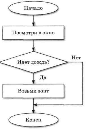
А вот так выглядят «кубики» из Node-RED.
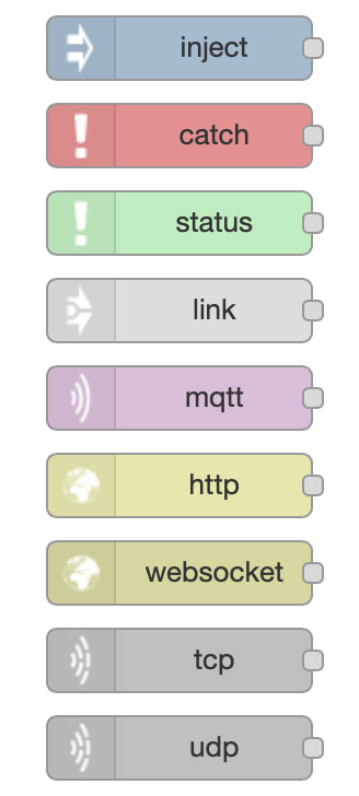
Урок информатики
А вот так выглядит описанный выше алгоритм с помощью этих кубиков
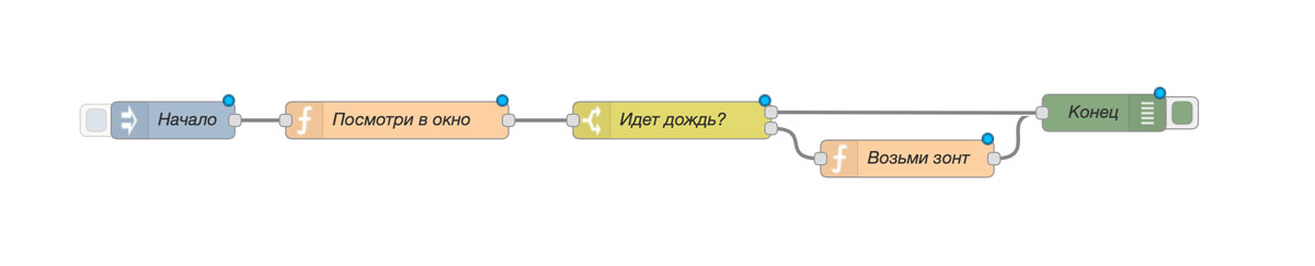
Давайте теперь разберем этот пример:
- Синий блок «Начало» — это наш блок с входными данными. В нашем примере это блок с помощью которого вы можете передать любые статичные данные. Чаще всего вы будете использовать этот блок, чтобы передать в ваш алгоритм какие-нибудь статичные данные, допустим, для проверки нарисованного вами алгоритма.
- Оранжевые блоки в нашем алгоритме выполняют некоторые действия. Допустим вы получили от вашего устройства значение «1», а в homekit вы хотите, чтобы это означало «включено», как раз с помощью таких блоков вы и пишите «преврати значение 1 в значение включено»
- Желтый блок — это условие. Один из наиболее используемых блоков в создании своего homekit устройства или автоматизаций. Аналогом этого блока можно придумать выражение «если так, то сделай так, а если вот так, то сделай вот так».
- Зеленый блок — это выходные данные. В данном случае это блок дебага. Опять же он используется для того, чтобы убедиться, что по итогам выполненного алгоритма вы получили то, что хотели.
Те «кубики», которые я описал выше — это стандартный набор блоков, доступный при базовой установки. Но для того, чтобы интегрировать наш Node-RED с вашими системами умного дома, вам потребуются кастомные плагины («паллеты»). Допустим для HomeKit используется плагин homekit-bridged, а для связи с home-assistant — этот.
На примере
Давайте разберем самый простой пример, который в отдельной статье распишем более подробно.
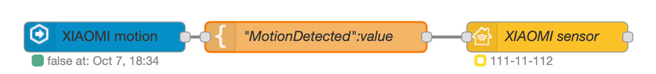
Как и в предыдущем алгоритме мы видим здесь три блока: входные данные, блок с необходимыми манипуляциями, блок с выходными данными.
Первый блок. Это блок Home Assistant, который настроен на прием информации от датчика движения Xiaomi. Как только датчик регистрирует движение, он передает об этом информацию. Но т.к. Home Assistant отдает информацию в одном формате, а HomeKit должен принимать его в другом, то нам нужен по середине оранжевый блок.
Второй блок. В этом блоке мы приводим полученную информацию от Home Assistant в понятную для HomeKit. Пример: от Home Assistant мы получаем просто булевое значение «true» или «false«, а в HomeKit передаем {«MotionDetected»: «true»} или {«MotionDetected»: «false»}.
Третий блок. Как только HomeKit получает информацию от оранжевого блока в нужном нам формате он отображает состояние датчика «сработал» или «нет».
Вместо итога
Вот примерно так это и выглядит. И так необходимо сделать каждое ваше устройство. Именно поэтому Node-RED это интересно, но о-о-о-о-очень муторно 🙂
Но при этом вы получаете, наверное, самый гибкий инструмент для автоматизации, который доступен каждому — нужно только немного попотеть :).
А если же вы готовы к бою, то приглашаю в наши статьи про Node-RED: раз, двась.