-
8/9/2019 ABB REL 511 Technical Reference Manual
1/272
-
8/9/2019 ABB REL 511 Technical Reference Manual
2/272
COPYRIGHT
WE RESERVE ALL RIGHTS TO THIS DOCUMENT, EVEN IN THE EVENT THAT A
PATENT IS ISSUED AND A DIFFERENTCOMMERCIAL PROPRIETARY RIGHT IS REGISTERED. IMPROPER USE, IN
PARTICULAR REPRODUCTION AND DIS-SEMINATION TO THIRD PARTIES, IS NOT
PERMITTED.THIS DOCUMENT HAS BEEN CAREFULLY CHECKED. IF THE USER
NEVERTHELESS DETECTS ANY ERRORS, HE ISASKED TO NOTIFY US AS SOON AS POSSIBLE.
THE DATA CONTAINED IN THIS MANUAL IS INTENDED SOLELY FOR THE
PRODUCT DESCRIPTION AND IS NOT TO BEDEEMED TO BE A STATEMENT OF GUARANTEED PROPERTIES. IN THE
INTERESTS OF OUR CUSTOMERS, WE CON-STANTLY SEEK TO ENSURE THAT OUR PRODUCTS ARE DEVELOPED TO THE
LATEST TECHNOLOGICAL STAN-DARDS. AS A RESULT, IT IS POSSIBLE THAT THERE MAY BE SOME
DIFFERENCES BETWEEN THE HW/SW PRODUCTAND THIS INFORMATION PRODUCT.
Manufacturer:
ABB Automation Products AB
Substation Automation Division
SE-721 59 Västerås
Sweden
Tel: +46 (0) 21 34 20 00
Fax: +46 (0) 21 14 69 18
Internet: http://www.abb.se
-
8/9/2019 ABB REL 511 Technical Reference Manual
3/272
Contents
PageChapter
Chapter 1 Introduction
……………………………………………………………
1Introduction to the technical reference manual
……………………………… 2About the complete set of
manuals to a terminal………………………. 2Design of the
Technical reference manual (TRM) ……………………..
3Related
documents……………………………………………………………….
6Chapter 2
General…………………………………………………………………..
7Terminal
identification………………………………………………………………..
8General terminal parameters
…………………………………………………. 8Basic
protection parameters
…………………………………………………..
8Calendar and clock
……………………………………………………………..
12Technical data
………………………………………………………………………..
13Case dimensions
………………………………………………………………..
13Weight
………………………………………………………………………………
17Unit
…………………………………………………………………………………..
17Environmental
properties……………………………………………………..
17Chapter 3 Common functions
………………………………………………. 21Time synchronisation
(TIME)…………………………………………………….
22Application
…………………………………………………………………………
22Function block
……………………………………………………………………
22Input and output signals
………………………………………………………
22Setting parameters
……………………………………………………………..
23Setting group selector
(GRP)…………………………………………………….
24Application
…………………………………………………………………………
24Logic diagram
…………………………………………………………………….
24Function block
……………………………………………………………………
24Input and output signals
………………………………………………………
25Setting lockout (HMI)
……………………………………………………………….
26Application
…………………………………………………………………………
26Function block
……………………………………………………………………
26Logic diagram
…………………………………………………………………….
26Input and output signals
………………………………………………………
27Setting parameters
……………………………………………………………..
27I/O system configurator (IOP)
…………………………………………………… 28Application
…………………………………………………………………………
28Logic diagram
…………………………………………………………………….
28Function block
……………………………………………………………………
29Input and output signals
………………………………………………………
29Self supervision (INT)
………………………………………………………………
30Application
…………………………………………………………………………
30Function block
……………………………………………………………………
30 -
8/9/2019 ABB REL 511 Technical Reference Manual
4/272
Contents
Logic diagram
…………………………………………………………………….
31Input and output
signals……………………………………………………….
33Technical data
……………………………………………………………………
33Logic function blocks
……………………………………………………………….
34Application
…………………………………………………………………………
34Inverter function block (INV)
………………………………………………… 34OR
function block
(OR)………………………………………………………..
34AND function block (AND)
……………………………………………………
35Timer function block (TM)
…………………………………………………….
36Timer long function block (TL)
……………………………………………… 37Pulse
timer function block
(TP)……………………………………………..
38Extended length pulse function block
(TQ)…………………………….. 38Exclusive OR function
block (XO)………………………………………….
39Set-reset function block
(SR)………………………………………………..
40Set-reset with memory function block (SM)
……………………………. 41Controllable gate function
block (GT) ……………………………………. 41Settable timer function block
(TS)…………………………………………. 42Technical
data
……………………………………………………………………
43Blocking of signals during test
…………………………………………………..
44Application
…………………………………………………………………………
44Function
block…………………………………………………………………….
44Input and output
signals……………………………………………………….
44Chapter 4 Line impedance
…………………………………………………….
45Distance protection
(ZM)…………………………………………………………..
46Application
…………………………………………………………………………
46Functionality……………………………………………………………………….
48Function block, zone 1-
3……………………………………………………..
50Function block, zone
4…………………………………………………………
51Function block, zone
5…………………………………………………………
52Logic diagram
…………………………………………………………………….
52Input and output signals, zone
1-3………………………………………… 55Input and
output signals, zone
4…………………………………………… 56Input and
output signals, zone
5…………………………………………… 57Setting
parameters, general
………………………………………………… 57Setting
parameters, zone 1-3
………………………………………………. 58Setting
parameters, zone
4…………………………………………………..
60Setting parameters, zone
5………………………………………………….. 62Setting parameters, directional measuring element
………………… 64Technical data
……………………………………………………………………
64Automatic switch onto fault logic
(SOTF)……………………………………. 66Application
…………………………………………………………………………
66Functionality……………………………………………………………………….
66Function
block…………………………………………………………………….
66Logic diagram
…………………………………………………………………….
67Input and output
signals……………………………………………………….
67Setting parameters
……………………………………………………………..
67Technical data
……………………………………………………………………
68Local acceleration logic
(ZCLC)…………………………………………………
69Application
…………………………………………………………………………
69 -
8/9/2019 ABB REL 511 Technical Reference Manual
5/272
Contents
Functionality
………………………………………………………………………
69Function block
……………………………………………………………………
69Logic diagram
…………………………………………………………………….
70Input and output signals
………………………………………………………
70Setting parameters
……………………………………………………………..
71General fault criteria (GFC)
………………………………………………………
72Application
…………………………………………………………………………
72Functionality
………………………………………………………………………
72Function block
……………………………………………………………………
73Logic diagram
…………………………………………………………………….
73Input and output signals
………………………………………………………
77Setting parameters
……………………………………………………………..
78Technical data
……………………………………………………………………
80Power swing detection (PSD)
……………………………………………………
82Application
…………………………………………………………………………
82Functionality
………………………………………………………………………
82Function block
……………………………………………………………………
83Logic diagram
…………………………………………………………………….
84Input and output signals
………………………………………………………
85Setting parameters
……………………………………………………………..
85Technical data
……………………………………………………………………
87Scheme communication logic for distanceprotection functions
(ZCOM) …………………………………………………..
89Application
…………………………………………………………………………
89Functionality
………………………………………………………………………
89Function block
……………………………………………………………………
90Logic diagram
…………………………………………………………………….
90Input and output signals
………………………………………………………
92Setting parameters
……………………………………………………………..
93Technical data
……………………………………………………………………
93Current reversal and WEI logic for distance protection
(ZCAL)……… 94Application
…………………………………………………………………………
94Functionality
………………………………………………………………………
94Function block
……………………………………………………………………
95Logic diagram
…………………………………………………………………….
96Input and output signals
………………………………………………………
97Setting parameters
……………………………………………………………..
99Technical data
……………………………………………………………………
99Chapter 5 Current
……………………………………………………………….
101Instantaneous overcurrent protection (IOC)
……………………………… 102Application
……………………………………………………………………….
102Functionality
…………………………………………………………………….
102Function block
………………………………………………………………….
102Logic diagram
…………………………………………………………………..
103Input and output signals
…………………………………………………….
103Setting parameters
……………………………………………………………
104Technical data
………………………………………………………………….
105Time delayed overcurrent protection (TOC)
……………………………… 106Application
……………………………………………………………………….
106 -
8/9/2019 ABB REL 511 Technical Reference Manual
6/272
Contents
Functionality……………………………………………………………………..
106Function
block…………………………………………………………………..
106Logic diagram
…………………………………………………………………..
107Input and output
signals……………………………………………………..
107Setting parameters
……………………………………………………………
108Technical data
………………………………………………………………….
109Two step time delayed phase overcurrent protection (TOC2)
……… 110Application
……………………………………………………………………….
110Functionality……………………………………………………………………..
110Function
block…………………………………………………………………..
110Logic diagram
…………………………………………………………………..
111Input and output
signals……………………………………………………..
111Setting parameters
……………………………………………………………
112Technical data
………………………………………………………………….
113Two step time delayed directional phaseovercurrent protection
(TOC3) ………………………………………………..
115Application
……………………………………………………………………….
115Functionality……………………………………………………………………..
115Function
block…………………………………………………………………..
116Logic diagram
…………………………………………………………………..
116Input and output
signals……………………………………………………..
120Setting parameters
……………………………………………………………
121Technical data
………………………………………………………………….
122Definite and inverse time-delayed residualovercurrent protection
(TEF) …………………………………………………..
124Application
……………………………………………………………………….
124Functionality……………………………………………………………………..
124Function
block…………………………………………………………………..
125Logic diagram
…………………………………………………………………..
126Input and output
signals……………………………………………………..
127Setting parameters
……………………………………………………………
127Scheme communication logic for residualovercurrent protection
(EFC) …………………………………………………
129Application
……………………………………………………………………….
129Functionality……………………………………………………………………..
129Function
block…………………………………………………………………..
129Logic diagram
…………………………………………………………………..
130Input and output
signals……………………………………………………..
130Setting parameters
……………………………………………………………
131Technical data
………………………………………………………………….
131Current reversal and weak end infeed logic for
residual overcurrent protection (EFCA)
……………………………………. 132Application
……………………………………………………………………….
132Design……………………………………………………………………………..
132Function
block…………………………………………………………………..
133Logic diagram
…………………………………………………………………..
133Input and output
signals……………………………………………………..
134Setting parameters
……………………………………………………………
135Technical data
………………………………………………………………….
135 -
8/9/2019 ABB REL 511 Technical Reference Manual
7/272
Contents
Chapter 6 Voltage
……………………………………………………………….
137Time delayed undervoltage protection (TUV)
……………………………. 138Application
……………………………………………………………………….
138Function block
………………………………………………………………….
138Logic diagram
…………………………………………………………………..
138Input and output signals
…………………………………………………….
139Setting parameters
……………………………………………………………
139Technical data
………………………………………………………………….
140Time delayed overvoltage protection (TOV)
……………………………… 141Application
……………………………………………………………………….
141Functionality
…………………………………………………………………….
141Function block
………………………………………………………………….
141Logic diagram
…………………………………………………………………..
142Input and output signals
…………………………………………………….
142Setting parameters
……………………………………………………………
143Technical data
………………………………………………………………….
144Chapter 7 Secondary system supervision
…………………………… 145Fuse failure supervision
(FUSE)………………………………………………
146Application
……………………………………………………………………….
146Functionality
…………………………………………………………………….
146Function block
………………………………………………………………….
146Logic diagram
…………………………………………………………………..
147Input and output signals
…………………………………………………….
148Setting parameters
……………………………………………………………
148Technical data
………………………………………………………………….
149Chapter 8 Control
……………………………………………………………….
151Synchrocheck (SYN)
……………………………………………………………..
152Application
……………………………………………………………………….
152Functionality
…………………………………………………………………….
152Function block
………………………………………………………………….
153Logic diagram
…………………………………………………………………..
154Input and output signals
…………………………………………………….
155Setting parameters
……………………………………………………………
156Technical data
………………………………………………………………….
158Automatic reclosing function (AR)
…………………………………………… 159Application
……………………………………………………………………….
159Functionality
…………………………………………………………………….
159Function block
………………………………………………………………….
160Input and output signals
…………………………………………………….
160Setting parameters
……………………………………………………………
163Technical data
………………………………………………………………….
165 -
8/9/2019 ABB REL 511 Technical Reference Manual
8/272
Contents
Chapter 9
Logic…………………………………………………………………..
167Trip logic (TR)
……………………………………………………………………….
168Application
……………………………………………………………………….
168Functionality……………………………………………………………………..
168Function
block…………………………………………………………………..
169Logic diagram
…………………………………………………………………..
169Input and output
signals……………………………………………………..
173Setting parameters
……………………………………………………………
174Technical data
………………………………………………………………….
175High speed binary output logic (HSBO)
……………………………………. 176Application
……………………………………………………………………….
176Functionality……………………………………………………………………..
176Function
block…………………………………………………………………..
176Logic diagram
…………………………………………………………………..
177Input and output
signals……………………………………………………..
178Setting parameters
……………………………………………………………
179Serial
communication……………………………………………………………..
181Application, common
…………………………………………………………
181Design,
common……………………………………………………………….
181Serial communication, SPA (SPA-bus V 2.4
protocol)………………… 183Application
……………………………………………………………………….
183Design……………………………………………………………………………..
183Setting parameters
……………………………………………………………
183Technical data
………………………………………………………………….
184Serial communication, IEC (IEC 60870-5-103 protocol)
……………… 185Application
……………………………………………………………………….
185Design……………………………………………………………………………..
185IEC 60870-5-103 information types
…………………………………….. 185Function
block…………………………………………………………………..
192Input and output
signals……………………………………………………..
192Setting parameters
……………………………………………………………
193Technical data
………………………………………………………………….
193Serial communication, LON
…………………………………………………….
194Application
……………………………………………………………………….
194Design……………………………………………………………………………..
194Technical data
………………………………………………………………….
194Event function (EV)
………………………………………………………………..
195Application
……………………………………………………………………….
195Design……………………………………………………………………………..
195Function
block…………………………………………………………………..
196Input and output
signals……………………………………………………..
197Setting parameters
……………………………………………………………
198Chapter 10
Monitoring…………………………………………………………..
201Disturbance report (DRP)
……………………………………………………….
202Application
……………………………………………………………………….
202Functionality……………………………………………………………………..
202Function
block…………………………………………………………………..
203Input and output
signals……………………………………………………..
204 -
8/9/2019 ABB REL 511 Technical Reference Manual
9/272
Contents
Setting parameters
……………………………………………………………
204Technical data
………………………………………………………………….
207Indications…………………………………………………………………………….
208Application
……………………………………………………………………….
208Functionality
…………………………………………………………………….
208Disturbance recorder
……………………………………………………………..
209Application
……………………………………………………………………….
209Functionality
…………………………………………………………………….
209Technical data
………………………………………………………………….
210Event recorder
………………………………………………………………………
211Application
……………………………………………………………………….
211Design
…………………………………………………………………………….
211Technical data
………………………………………………………………….
211Fault locator (FLOC)
………………………………………………………………
212Application
……………………………………………………………………….
212Functionality
…………………………………………………………………….
212Function block
………………………………………………………………….
213Input and output signals
…………………………………………………….
213Setting parameters
……………………………………………………………
214Technical data
………………………………………………………………….
215Monitoring of AC analogue measurements
………………………………. 216Application
……………………………………………………………………….
216Functionality
…………………………………………………………………….
216Function block
………………………………………………………………….
216Input and output signals
…………………………………………………….
217Setting parameters
……………………………………………………………
218Technical data
………………………………………………………………….
228Monitoring of DC analogue measurements
………………………………. 229Application
……………………………………………………………………….
229Function block
………………………………………………………………….
229Input and output signals
…………………………………………………….
229Setting parameters
……………………………………………………………
230Technical data
………………………………………………………………….
233Chapter 11 Hardware
modules………………………………………………
235Modules
……………………………………………………………………………….
236Transformer input module (TRM)
……………………………………………. 238Design
…………………………………………………………………………….
238Technical data
………………………………………………………………….
238A/D-conversion module (ADM)
……………………………………………….. 240Design
…………………………………………………………………………….
240Binary I/O capabilities
…………………………………………………………….
241Application
……………………………………………………………………….
241Design
…………………………………………………………………………….
241Technical data
………………………………………………………………….
241Binary input module (BIM)
………………………………………………………
243Application
……………………………………………………………………….
243Design
…………………………………………………………………………….
243Function block
………………………………………………………………….
243Input and output signals
…………………………………………………….
243 -
8/9/2019 ABB REL 511 Technical Reference Manual
10/272
Contents
Binary output module (BOM)
…………………………………………………..
245Application
……………………………………………………………………….
245Design……………………………………………………………………………..
245Function
block…………………………………………………………………..
246Input and output
signals……………………………………………………..
246Power supply module (PSM)
…………………………………………………..
247Application
……………………………………………………………………….
247Design……………………………………………………………………………..
247Function
block…………………………………………………………………..
247Input and output
signals……………………………………………………..
247Technical data
………………………………………………………………….
248Human-machine-interface modules (HMI)
………………………………… 249Application
……………………………………………………………………….
249Design……………………………………………………………………………..
249Technical data
………………………………………………………………….
250Serial communication modules
(SCM)……………………………………… 251Design, SPA/IEC
………………………………………………………………
251Design, LON
…………………………………………………………………….
251Technical data
………………………………………………………………….
251Chapter 12 Diagrams
…………………………………………………………….
253Terminal diagrams
…………………………………………………………………
254Terminal diagram, REL 511-C1
………………………………………….. 254 -
8/9/2019 ABB REL 511 Technical Reference Manual
11/272
1
About this chapter Chapter 1
Introduction
Chapter 1 Introduction
About this chapter
This chapter introduces you to the manual as such.
-
8/9/2019 ABB REL 511 Technical Reference Manual
12/272
2
Introduction to the technical referencemanual
Chapter 1
Introduction
1 Introduction to the technical reference manual
1.1 About the complete set of manuals to a terminal
The complete package of manuals to a terminal is named users
manual (UM). The Us-ers manual consists of four different manuals:
The Application Manual (AM) contains descriptions, such as
application and func-tionality descriptions as well as setting calculation examples
sorted per function. Theapplication manual should be used when designing and engineering
the protection ter-minal to find out where and for what a typical protection
function could be used. Themanual should also be used when calculating settings and
creating configurations.The Technical Reference Manual (TRM) contains technical
descriptions, such asfunction blocks, logic diagrams, input and output signals,
setting parameter tables andtechnical data sorted per function. The technical reference
manual should be used as atechnical reference during the
engineering phase, installation and commissioning phaseand during the normal service phase.
The Operator´s Manual (OM) contains instructions on how to
operate the protectionterminal during normal service (after commissioning and before
periodic maintenancetests). The operator´s manual could be used to find out how to
handle disturbances orhow to view calculated and measured network data in order to
determine the reason ofa fault.
The Installation and Commissioning Manual (ICM) contains
instructions on how toinstall and commission the protection terminal. The manual can
also be used as a refer-ence if a periodic test is performed. The manual covers
procedures for mechanical andelectrical installation, energising and checking of external
circuitry, setting and config-uration as well as verifying settings and performing a
directionality test. The chaptersand sections are organised in the chronological order (indicated
by chapter/sectionnumbers) the protection terminal should be installed and
commissioned.Application
manual
Technical
reference
manual
Installation and
commissioning
manual
Operator´s
manual
en01000044.vsd
-
8/9/2019 ABB REL 511 Technical Reference Manual
13/272
3
Introduction to the technical referencemanual
Chapter 1
Introduction
1.2 Design of the Technical reference manual (TRM)
The description of each terminal related function follows the
same structure (where ap-plicable):
Application
States the most important reasons for the implementation of a
particular protectionfunction.
Functionality/Design
Presents the general concept of a function.
Function block
Each function block is imaged by a graphical symbol.
Input signals are always on the left side, and output signals on
the right side. Settingsare not displayed. A special kind of settings are sometimes
available. These are sup-posed to be connected to constants in the configuration scheme,
and are therefore de-picted as inputs. Such signals will be found in the signal list
but described in the settingstable.
Figure 1: Function block symbol example
Logic diagram
The description of the design is chiefly based on simplified
logic diagrams, which useIEC symbols, for the presentation of different functions,
conditions etc. The functionsare presented as a closed block with the most important internal
logic circuits and con-figurable functional inputs and outputs.
Completely configurable binary inputs/outputs and functional
inputs/outputs enable theuser to prepare the REx 5xx with his own configuration of
different functions, accord-ing to application needs and standard
practice.TUV
BLOCK
BLKTR
VTSU
TRIP
STL1
STL2
STL3
START
xx00000207.vsd
-
8/9/2019 ABB REL 511 Technical Reference Manual
14/272
4
Introduction to the technical referencemanual
Chapter 1
Introduction
Figure 2: Function block diagram example
The names of the configurable logic signals consist of two parts
divided by dashes. Thefirst part consists of up to four letters and presents the
abbreviated name for the corre-sponding function. The second part presents the functionality of
the particular signal.According to this explanation, the meaning of the signal
TUV—BLKTR is as follows.• The first part of the signal, TUV- represents the adherence to
the Time delayed Un-der-Voltage function.
• The second part of the signal name, BLKTR informs the user
that the signal willBLocK the TRip from the under-voltage function, when its value
is a logical one (1).Different binary signals have special symbols with the following
significance:• Signals drawn to the box frame to the left present functional
input signals. It is pos-sible to configure them to functional output signals of other
functions as well as tobinary input terminals of the REx 5xx terminal. Examples are
TUV—BLKTR, TUV--BLOCK and TUV—VTSU.Signals in frames with a shaded area on
their right sidepresent the logical setting signals. Their values are high (1)
only when the corre-sponding setting parameter is set to the symbolic value
specified within the frame.Example is the signal Operation = On. These signals are not
configurable. Their log-ical values correspond automatically to the selected setting
value.The internal sig-nals are usually dedicated to a certain function. They are
normally not available forTUV—BLKTR
TUV—BLOCK
TUV—VTSU >1
STUL1
STUL2
&
&
&STUL3
Operation = On
>1& t
tt
15 msTUV—TRIP
TUV—START
TUV—STL1
TUV—STL2
TUV—STL3
t15 ms
t
15 ms
t
15 ms
t
15 ms
TRIP — cont.
xx01000170.vsd
-
8/9/2019 ABB REL 511 Technical Reference Manual
15/272
5
Introduction to the technical referencemanual
Chapter 1
Introduction
configuration purposes. Examples in are signals STUL1, STUL2 and
STUL3.Thefunctional output signals, drawn to the box frame to the right,
present the logical out-puts of functions and are available for configuration purposes.
The user can config-ure them to binary outputs from the terminal or to inputs of
different functions.Typical examples in are signals TUV—TRIP,
TUV—START etc.Other internal signals configurated to other function blocks are
written on a line with anidentity and a cont. reference. An example is the signal TRIP —
cont. The signal can befound in the corresponding function with the same identity.
Input and output signals
The signal lists contain all available input and output signals
of the function block, onetable for input signals and one for output signals.
Table 1: Input signals for the TUV (TUV—) function block
Table 2: Output signals for the TUV (TUV—) function block
Setting parameters
The setting parameters table contains all available settings of
the function block. If afunction consists of more than one block,
each block is listed in a separate table.Signal Description
BLOCK Block undervoltage function
BLKTR Block of trip from time delayed undervoltage function
VTSU Block from voltage transformer circuit supervision
Signal DescriptionTRIP Trip by time delayed undervoltage
functionSTL1 Start phase undervoltage phase L1
STL2 Start phase undervoltage phase L2
STL3 Start phase undervoltage phase L3
START Start phase undervoltage
-
8/9/2019 ABB REL 511 Technical Reference Manual
16/272
6
Introduction to the technical referencemanual
Chapter 1
Introduction
Table 3: Setting parameters for the time delayed undervoltage
protection TUV(TUV—) functionTechnical data
The technical data specifies the terminal in general, the
functions and the hardwaremodules.
1.3 Related documents
Parameter Range Default Unit Description
Operation Off, On Off — Operating mode for TUV function
UPE< 10-100
Step: 1
70 % of
U1b
Operate phase voltage
t 0.000-
60.000
Step: 0.001
0.000 s Time delay
Documents related to REL 511-C1*2.3 Identity number
Operator’s manual 1MRK 506 096-UEN
Installation and commissioning manual 1MRK 506 098-UEN
Technical reference manual 1MRK 506 097-UEN
Application manual 1MRK 506 116-UEN
Technical overview brochure 1MRK 506 095-BEN
-
8/9/2019 ABB REL 511 Technical Reference Manual
17/272
7
About this chapter Chapter 2
General
Chapter 2 General
About this chapter
This chapter describes the terminal in general.
-
8/9/2019 ABB REL 511 Technical Reference Manual
18/272
8
Terminal identification Chapter 2
General
1 Terminal identification
1.1 General terminal parameters
Use the terminal identifiers to name the individual terminal for
identification purposes.Use the terminal reports to check serial numbers of the terminal
and installed modulesand to check the firmware version.
Identifiers and reports are accessible by using the HMI as well
as by SMS or SCS sys-tems.
Table 4: Set parameters for the general terminal parameters
function1.2 Basic protection parameters
Path in HMI-tree: Configuration/AnalogInputs/General
Table 5: Setting parameters for analogInputs — General
Path in HMI-tree: Configuration/AnalogInputs/U1-U5
Parameter Range Default Unit Description
Station Name 0-16 Station
Name
char Identity name for the station
Station No 0-99999 0 — Identity number for the station
Object Name 0-16 Object
Name
char Identity name for the protected
object
Object No 0-99999 0 — Identity number for the protected
object
Unit Name 0-16 Unit Name char Identity name for the terminal
Unit No 0-99999 0 — Identity number for the terminal
Parameter Range Default Unit Description
CTEarth In/Out Out — Direction of CT earthing
fr 50, 60, 16
2/3
50 Hz System frequency
-
8/9/2019 ABB REL 511 Technical Reference Manual
19/272
9
Terminal identification Chapter 2
General
Table 6: Analog Inputs — Voltage
Parameter Range Default Unit Description
U1r * 10.000 —
500.000
Step: 0.001
63.509 V Rated voltage of transformer on
input U1
U1b 30.000 —
500.000
Step:0.001
63.509 V Base voltage of input U1
U1Scale 1.000 —
20000.000
Step: 0.001
2000.000 — Main voltage transformer ratio, input
U1
Name_U1 0 — 13 U1 char User-defined name of input U1
U2r * 10.000 —
500.000
Step: 0.001
63.509 V Rated voltage of transformer on
input U2
U2b 30.000 —
500.000
Step: 0.001
63.509 V Base voltage of input U2
U2Scale 1.000 —
20000.000
Step: 0.001
2000.000 — Main voltage transformer ratio, input
U2
Name_U2 0 — 13 U2 char User-defined name of input U2
U3r * 10.000 —
500.000
Step: 0.001
63.509 V Rated voltage of transformer on
input U3
U3b 30.000 —
500.000
Step: 0.001
63.509 V Base voltage of input U3
U3Scale 1.000 —
20000.000
Step: 0.001
2000.000 — Main voltage transformer ratio, input
U3
Name_U3 0 — 13 U3 char User-defined name of input U3
-
8/9/2019 ABB REL 511 Technical Reference Manual
20/272
-
8/9/2019 ABB REL 511 Technical Reference Manual
21/272
11
Terminal identification Chapter 2
General
Table 7: Analog Inputs — Current
Parameter Range Default Unit Description
I1r * 0.1000 —
10.0000
Step:
0.0001
1.0000 A Rated current of transformer on
input I1
I1b 0.1 — 10.0
Step: 0.1
1.0 A Base current of input I1
I1Scale 1.000 —
40000.000
Step: 0.001
2000.000 — Main current transformer ratio,
input I1
Name_I1 0 — 13 I1 char User-defined name of input I1
I2r * 0.1000 —
10.0000
Step:
0.0001
1.0000 A Rated current of transformer on
input I2
I2b 0.1 — 10.0
Step: 0.1
1.0 A Base current of input I2
I2Scale 1.000 —
40000.000
Step:0.001
2000.000 — Main current transformer ratio,
input I2
Name_I2 0 — 13 I2 char User-defined name of input I2
I3r * 0.1000 —
10.0000
Step:
0.0001
1.0000 A Rated current of transformer on
input I3
I3b 0.1 — 10.0
Step: 0.1
1.0 A Base current of input I3
I3Scale 1.000 —
40000.000
Step: 0.001
2000.000 — Main current transformer ratio,
input I3
Name_I3 0 — 13 I3 char User-defined name of input I3
-
8/9/2019 ABB REL 511 Technical Reference Manual
22/272
12
Terminal identification Chapter 2
General
1.3 Calendar and clock
Table 8: Calendar and clock
I4r * 0.1000 —
10.0000
Step:
0.0001
1.0000 A Rated current of transformer on
input I4
I4b 0.1 — 10.0
Step: 0.1
1.0 A Base current of input I4
I4Scale 1.000 —
40000.000
Step: 0.001
2000.000 — Main current transformer ratio,
input I4
Name_I4 0 — 13 I4 char User-defined name of input I4
I5r * 0.1000 —
10.0000
Step:
0.0001
1.0000 A Rated current of transformer on
input I5
I5b 0.1 — 10.0
Step: 0.1
1.0 A Base current of input I5
I5Scale 1.000 —
40000.000
Step: 0.001
2000.000 — Main current transformer ratio,
input I5
Name_I5 0 — 13 I5 char User-defined name of input I5
*) Setting is done through the local HMI only
Parameter Range Default Unit Description
Parameter Range
Built-in calender 30 years with leap years
-
8/9/2019 ABB REL 511 Technical Reference Manual
23/272
13
Technical data Chapter 2
General
2 Technical data
2.1 Case dimensions
Figure 3: Hardware structure of the 1/2 of full width 19”
case -
8/9/2019 ABB REL 511 Technical Reference Manual
24/272
14
Technical data Chapter 2
General
Diagrams (Dimensions)
96000309.tif
96000310.tif
Case
size
A B C D E F G H I J K
6U x 1/2 223.7 205.7 203.7 — —
6U x 3/4 265.9 336 204.1 245.1 255.8 318 190.5 316 — 227.6 —
6U x 1/1 448.3 430.3 428.3 465.1
*)
482.6
*) equal to 19” (mm)
-
8/9/2019 ABB REL 511 Technical Reference Manual
25/272
15
Technical data Chapter 2
General
Panel cut-outs for REx 500 series
Flush mounting Semi-flush mounting
97000025.tif97000026.tif
Case size
Cut-out dimensions (mm)
A+/-1 B+/-1
6U x 1/2 210.1 259.3
6U x 3/4 322.4 259.3
6U x 1/1 434.7 259.3
C = 4-10 mm
D = 16.5 mm
E = 187.6 mm without protection cover, 228.6 mm with protection
coverF = 106.5 mm
G = 97.6 mm without protection cover, 138.6 mm with protection
cover -
8/9/2019 ABB REL 511 Technical Reference Manual
26/272
16
Technical data Chapter 2
General
The flush mounting kits are available in three designs, suitable
for 1/2, 3/4 or full widthterminals and consists of four fasteners (4) with appropriate
mounting details and a seal-ing strip (1) providing IP54 class protection for fastening to
the terminal (5). The semi-flush mounting kit adds a distance frame (2). An additional
sealing strip (3) can beordered for semiflush mounting to provide
IP54 class protection.Figure 4: The flush mounting kit
xx00000129.eps
1
2
3
4
5
6
xx01000049.vsden01000047.vsd
-
8/9/2019 ABB REL 511 Technical Reference Manual
27/272
17
Technical data Chapter 2
General
2.2 Weight
Table 9: Weight
2.3 Unit
Table 10: Unit
2.4 Environmental properties
Table 11: Temperature and humidity influence
Case size (mm) A B C D E
6U x 1/2 292 267.1
6U x 3/4 404.3 379.4 272.8 390 247
6U x 1/1 516 491.1
Case size Weight
6U x 1/2 ≤ 8.5 kg
6U x 3/4 ≤ 11 kg
6U x 1/1 ≤ 18 kg
Material Steel sheet
Front plate Aluminium profile with cut-out for HMI
Surface treatment Aluzink preplated steel
Finish Light beige (NCS 1704-Y15R)
Degree of protection Front side: IP40, IP54 with optional
sealing strip Rear side: IP20Parameter Rated value Nominal range Influence
Storage temperature — -40 °C to +70 °C —
Ambient temperature (duringoperation)
+20 °C -5 °C to +55 °C 0.01%/°C, within nomi-nal range
Correct function within
operative range
Relative humidity 10%-90% 10%-90% —
-
8/9/2019 ABB REL 511 Technical Reference Manual
28/272
18
Technical data Chapter 2
General
Table 12: Auxiliary DC supply voltage influence on functionality
during operationTable 13: Electromagnetic compatibility
Table 14: Insulation
Table 15: CE compliance
Dependence on: Within nominal
range
Within operative range
Ripple, max 12% or EL Negligible Correct function
Interrupted auxiliary
DC voltage
Without reset
-
8/9/2019 ABB REL 511 Technical Reference Manual
29/272
19
Technical data Chapter 2
General
Table 16: Mechanical tests
Test Type test values Reference standards
Vibration Class I IEC 60255-21-1
Shock and bump Class I IEC 60255-21-2
Seismic Class I IEC 60255-21-3
-
8/9/2019 ABB REL 511 Technical Reference Manual
30/272
20
Technical data Chapter 2
General
-
8/9/2019 ABB REL 511 Technical Reference Manual
31/272
21
About this chapter Chapter 3
Common functions
Chapter 3 Common functions
About this chapter
This chapter presents the common functions in the terminal.
-
8/9/2019 ABB REL 511 Technical Reference Manual
32/272
22
Time synchronisation (TIME) Chapter 3
Common functions
1 Time synchronisation (TIME)
1.1 Application
Use the time synchronization source selector to select a common
source of absolutetime for the terminal when it is a part of a protection system.
This makes comparison ofevents and disturbance data between all terminals in a system
possible.1.2 Function block
1.3 Input and output signals
Table 17: Input signals for the TIME (TIME-) function block
Table 18: Output signals for the TIME (TIME-) function block
xx00000171.vsd
TIME-
TIME
MINSYNC
SYNCSRC
RTCERR
SYNCERR
Signal Description
MINSYNC Minute pulse input
SYNCSRC Synchronization source selector input. See settings
fordetails.
Signal Description
RTCERR Real time clock error
SYNCERR Time synchronisation error
-
8/9/2019 ABB REL 511 Technical Reference Manual
33/272
23
Time synchronisation (TIME) Chapter 3
Common functions
1.4 Setting parameters
Table 19: Setting parameters for the time synchronization source
selector func-tionParameter Range Default Unit Description
SYNCSRC 0-5 0 — Selects the time synchronization
source:
0: No source. Internal real time clock
is used without fine tuning.
1: LON bus
2: SPA bus
3: IEC 870-5-103 bus
4: Minute pulse, positive flank
5: Minute pulse, negative flank
-
8/9/2019 ABB REL 511 Technical Reference Manual
34/272
24
Setting group selector (GRP) Chapter 3
Common functions
2 Setting group selector (GRP)
2.1 Application
Use the four sets of settings to optimize the terminal’s
operation for different systemconditions. By creating and switching between fine tuned setting
sets, either from thehuman-machine interface or configurable binary inputs, results
in a highly adaptableterminal that can cope with a variety of system scenarios.
2.2 Logic diagram
Figure 5: Connection of the function to external circuits
2.3 Function block
GRP—ACTGRP1
GRP—ACTGRP2
GRP—ACTGRP3
GRP—ACTGRP4
IOx-Bly1
IOx-Bly2
IOx-Bly3
IOx-Bly4
+RL2
∅
∅
∅
∅
en01000144.vsd
ACTIVATE GROUP 4
ACTIVATE GROUP 3
ACTIVATE GROUP 2
ACTIVATE GROUP 1
xx00000153.vsd
GRP—
ACTIVEGROUP
ACTGRP1
ACTGRP2
ACTGRP3
ACTGRP4
GRP1
GRP2
GRP3
GRP4
-
8/9/2019 ABB REL 511 Technical Reference Manual
35/272
25
Setting group selector (GRP) Chapter 3
Common functions
2.4 Input and output signals
Table 20: Input signals for the ACTIVEGROUP (GRP—) function
blockTable 21: Output signals for the ACTIVEGROUP (GRP—) function
blockSignal Description
ACTGRP1 Selects setting group 1 as active
ACTGRP2 Selects setting group 2 as active
ACTGRP3 Selects setting group 3 as active
ACTGRP4 Selects setting group 4 as active
Signal Description
GRP1 Setting group 1 is active
GRP2 Setting group 2 is active
GRP3 Setting group 3 is active
GRP4 Setting group 4 is active
-
8/9/2019 ABB REL 511 Technical Reference Manual
36/272
26
Setting lockout (HMI) Chapter 3
Common functions
3 Setting lockout (HMI)
3.1 Application
Unpermitted or uncoordinated changes by unauthorized personnel
may cause severedamage to primary and secondary power circuits. Use the setting
lockout function toprevent unauthorized setting changes and to control when setting
changes are allowed.By adding a key switch connected to a binary input a simple
setting change control cir-cuit can be built simply allowing only authorized keyholders to
make setting changesfrom the built-in HMI.
3.2 Function block
3.3 Logic diagram
Figure 6: Connection and logic diagram for the BLOCKSET
functionxx00000154.vsd
SETTING RESTRICTION
BLOCKSET
SettingRestrict=BlockRESTRICT
SETTINGS
HMI—BLOCKSET
&SWITCH
WITH KEY
+
Rex 5xx
en01000152.vsd
-
8/9/2019 ABB REL 511 Technical Reference Manual
37/272
27
Setting lockout (HMI) Chapter 3
Common functions
3.4 Input and output signals
Table 22: Input signals for the SETTING RESTRICTION function
block3.5 Setting parameters
Table 23: Setting parameters for the setting lockout
functionSignal Description
BLOCKSET Input signal to block setting and/or configuration
changesfrom the local HMI. WARNING: Read the instructions
beforeuse. Default configuration to NONE-NOSIGNAL.
Parameter Range Default Unit Description
SettingRestrict Open,Block
Open — Open: Setting parameters can bechanged.
Block: Setting parameters can only
be changed if the logic state of the
BLOCKSET input is zero.
-
8/9/2019 ABB REL 511 Technical Reference Manual
38/272
28
I/O system configurator (IOP) Chapter 3
Common functions
4 I/O system configurator (IOP)
4.1 Application
The I/O system configurator must be used in order for the
terminal’s software to recog-nize added modules and to create internal address mappings
between modules and pro-tections and other functions.
4.2 Logic diagram
Figure 7: Example of an I/O-configuration in the graphical tool
CAP 531 for a REx 5xxwith two BIMs.
IOP1-
S11
S14
S15
S16
S17
S18
S13
S12
S19
S20
S21
S23
S22
I/OPosition
S24
S25
S26
S27
S28
S30
S32
S34
S36
IO01-
IO02-
I/O-module
I/O-module
POSITION ERROR
BI1
BI6
.
.
.
POSITION ERROR
BI1
BI6
.
.
.
en01000143.vsd
-
8/9/2019 ABB REL 511 Technical Reference Manual
39/272
29
I/O system configurator (IOP) Chapter 3
Common functions
4.3 Function block
4.4 Input and output signals
Table 24: Output signals for the I/OPOSITION (IOPn-) function
blockxx00000238.vsd
IOP1-
I/OPOSITION
S11
S12
S13
S14
S15
S16
S17
S18
S19
S20
S21
S22
S23
S24
S25
S26
S27S28
S29
S30
S31
S32
S33
S34
S35
S36
Signal Description
Snn Slot position nn (nn=11-39)
-
8/9/2019 ABB REL 511 Technical Reference Manual
40/272
30
Self supervision (INT) Chapter 3
Common functions
5 Self supervision (INT)
5.1 Application
Use the local HMI, SMS or SCS system to view the status of the
self-supervision func-tion. The self-supervision operates continuously and
includes:• Normal micro-processor watchdog function
• Checking of digitized measuring signals
• Checksum verification of PROM contents and all types of signal
communication5.2 Function block
xx00000169.vsd
INT—
INTERNSIGNALS
FAIL
WARNING
CPUFAIL
CPUWARN
ADC
SETCHGD
-
8/9/2019 ABB REL 511 Technical Reference Manual
41/272
31
Self supervision (INT) Chapter 3
Common functions
5.3 Logic diagram
Figure 8: Hardware self-supervision, potential-free alarm
contact.Power supply fault
WatchdogTX overflowMaster resp.Supply fault
ReBoot I/O
Checksum fault
Sending reports
DSP fault
Supply faultParameter check
Power supplymodule
I/O nodes
A/D conv.module
Main CPU
&
Fault
Fault
Fault
Fault
INTERNALFAIL
I/O nodes = BIM, BOM, IOM PSM, MIM or DCMDSP = Digital
Signal Processorxxxx = Inverted signal99000034.vsd
-
8/9/2019 ABB REL 511 Technical Reference Manual
42/272
32
Self supervision (INT) Chapter 3
Common functions
Figure 9: Software self-supervision, function block INTernal
signalsChecksum
Node reports
Synch error
NO RX Data
NO TX Clock
Check RemError
&
>1
>1
INT—ADC
Send Rem Error
OK
OK
>1TIME-RTCERR INT—CPUWARN
>1
TIME-SYNCERR
RTC-WARNING
INT—CPUWARN
INT—WARNING
Watchdog
Check CRC
RAM check
DSP Modules, 1-12
OK
OK
OK&
OKINT—CPUFAIL
Parameter check
Watchdog
Flow control
&
OK
OK
OK&
>1
INT—CPUFAIL
INT—ADC
I/O node FAILINT—FAIL
Start-up self-test Fault
MainCPU
Remoteterminal
communication
A/D Converter
Module
RTC-WARNING = DIFL-COMFAIL or RTC1-COMFAIL +
RTC2-COMFAIL
I/O node = BIM, BOM, IOM, PSM, MIM, DCM (described in the
hardware design)99000035.vsd
>1
RTC-WARNING
-
8/9/2019 ABB REL 511 Technical Reference Manual
43/272
33
Self supervision (INT) Chapter 3
Common functions
5.4 Input and output signals
Table 25: Output signals for the INTERNSIGNALS (INT—) function
block5.5 Technical data
Table 26: Internal event list
Signal Description
FAIL Internal fail status
WARNING Internal warning status
CPUFAIL CPU module fail status
CPUWARN CPU module warning status
ADC A/D-converter error
SETCHGD Setting changed
Data Value
Recording manner Continuous, event controlled
List size 40 events, first in-first out
-
8/9/2019 ABB REL 511 Technical Reference Manual
44/272
34
Logic function blocks Chapter 3
Common functions
6 Logic function blocks
6.1 Application
The user can with the available logic function blocks build
logic functions and config-ure the terminal to meet application specific requirements.
Different protection, control, and monitoring functions within
the REx 5xx terminalsare quite independent as far as their configuration in the
terminal is concerned. The usercan not change the basic algorithms for different functions. But
these functions com-bined with the logic function blocks can be used to create
application specific function-ality.
6.2 Inverter function block (INV)
The inverter function block INV has one input and one output,
where the output is ininverse ratio to the input.
Table 27: Input signals for the INV (IVnn-) function block
Table 28: Output signals for the INV (IVnn-) function block
6.3 OR function block (OR)
The OR function is used to form general combinatory expressions
with boolean vari-ables. The OR function block has six inputs and two outputs. One
of the outputs is in-verted.
Signal Description
INPUT Logic INV-Input to INV gate
Signal Description
Out Logic INV-Output from INV gate
xx00000158.vsd
IV01-
INV
INPUT OUT
-
8/9/2019 ABB REL 511 Technical Reference Manual
45/272
35
Logic function blocks Chapter 3
Common functions
Table 29: Input signals for the OR (Onnn-) function block
Table 30: Output signals for the OR (Onnn-) function block
6.4 AND function block (AND)
The AND function is used to form general combinatory expressions
with boolean vari-ables.The AND function block has four inputs and two outputs.
One of the inputs andone of the outputs are inverted.
Signal Description
INPUT1 Input 1 to OR gate
INPUT2 Input 2 to OR gate
INPUT3 Input 3 to OR gate
INPUT4 Input 4 to OR gate
INPUT5 Input 5 to OR gate
INPUT6 Input 6 to OR gate
Signal Description
OUT Output from OR gate
NOUT Inverted output from OR gate
xx00000159.vsd
O001-
OR
INPUT1
INPUT2
INPUT3
INPUT4
INPUT5
INPUT6
OUT
NOUT
xx00000160.vsd
A001-
AND
INPUT1
INPUT2INPUT3
INPUT4N
OUT
NOUT
-
8/9/2019 ABB REL 511 Technical Reference Manual
46/272
36
Logic function blocks Chapter 3
Common functions
Table 31: Input signals for the AND (Annn-) function block
Table 32: Output signals for the AND (Annn-) function block
6.5 Timer function block (TM)
The function block TM timer has drop-out and pick-up delayed
outputs related to theinput signal. The timer has a settable time delay (parameter T)
between 0.000 and60.000 s in steps of 0.001 s.
Table 33: Input signals for the TIMER (TMnn-) function block
Table 34: Output signals for the TIMER (TMnn-) function
blockSignal Description
INPUT1 Input 1 to AND gate
INPUT2 Input 2 to AND gate
INPUT3 Input 3 to AND gate
INPUT4N Input 4 (inverted) to AND gate
Signal Description
OUT Output from AND gate
NOUT Inverted output from AND gate
Signal Description
INPUT Input to timer
T Time value. See setting parameters
Signal Description
OFF Output from timer, drop-out delayed
ON Output from timer , pick-up delayed
xx00000161.vsd
TM01-
TIMER
INPUTT
OFFON
-
8/9/2019 ABB REL 511 Technical Reference Manual
47/272
37
Logic function blocks Chapter 3
Common functions
6.5.1 Setting parameters
Table 35: Setting parameters for the Timer (TMnn-) function
6.6 Timer long function block (TL)
The function block TL timer with extended maximum time delay at
pick-up and at drop-out, is identical with the TM timer. The difference is the
longer time delay, settable be-tween 0.0 and 90000.0 s in steps of 0.1 s
Table 36: Input signals for the TIMERLONG (TLnn-) function
blockTable 37: Output signals for the TIMERLONG (TLnn-) function
block6.6.1 Setting parameters
Table 38: Setting parameters for the TimerLong (TLnn-)
functionParameter Range Default Unit Description
T 0.000-
60.000
Step: 0.001
0.000 s Delay for timer nn
Signal Description
INPUT Input to long timer
T Time value. See setting parameters
Signal Description
OFF Output from long timer, drop-out delayed
ON Output from long timer, pick-up delayed
xx00000162.vsd
TL01-
TIMERLONG
INPUT
T
OFF
ON
Parameter Range Default Unit Description
T 0.0-90000.0
Step:0.1
0.0 s Delay for TLnn function
-
8/9/2019 ABB REL 511 Technical Reference Manual
48/272
38
Logic function blocks Chapter 3
Common functions
6.7 Pulse timer function block (TP)
The pulse function can be used, for example, for pulse
extensions or limiting of opera-tion of outputs. The pulse timer TP has a settable length of a
pulse between 0.000 s and60.000 s in steps of 0.010 s.Table 39: Input signals for the TP (TPnn-) function block
Table 40: Output signals for the TP (TPnn-) function block
6.7.1 Setting parameters
Table 41: Setting parameters for the Pulse (TPnn-) function
6.8 Extended length pulse function block (TQ)
The function block TQ pulse timer with extended maximum pulse
length, is identicalwith the TP pulse timer. The difference is the longer pulse
length, settable between 0.0and 90000.0 s in steps of 0.1 s.
Signal Description
INPUT Input to pulse timer
T Pulse length. See setting parameters
Signal Description
OUT Output from pulse timer
xx00000163.vsd
TP01-
PULSE
INPUT
T
OUT
Parameter Range Default Unit Description
T 0.000-
60.000
Step:0.010
0.010 s Pulse length
-
8/9/2019 ABB REL 511 Technical Reference Manual
49/272
39
Logic function blocks Chapter 3
Common functions
Table 42: Input signals for the PULSELONG (TQnn-) function
blockTable 43: Output signals for the PULSELONG (TQnn-) function
block6.8.1 Setting parameters
Table 44: Setting parameters for the PulseLong (TQnn-)
function6.9 Exclusive OR function block (XO)
The exclusive OR function XOR is used to generate combinatory
expressions withboolean variables. The function block XOR has two inputs and two
outputs. One of theoutputs is inverted. The output signal is 1 if the input signals
are different and 0 if theyare equal.
Signal Description
INPUT Input to pulse long timer
T Pulse length. See setting parameters
Signal Description
OUT Output from pulse long timer
xx00000164.vsd
TQ01-
PULSELONG
INPUT
T
OUT
Parameter Range Default Unit Description
T 0.0-90000.0
Step: 0.1
0.0 s Pulse length
xx00000165.vsd
XO01-
XOR
INPUT1
INPUT2
OUT
NOUT
-
8/9/2019 ABB REL 511 Technical Reference Manual
50/272
40
Logic function blocks Chapter 3
Common functions
Table 45: Input signals for the XOR (XOnn-) function block
Table 46: Output signals for the XOR (XOnn-) function block
6.10 Set-reset function block (SR)
The Set-Reset (SR) function is a flip-flop that can set or reset
an output from two inputsrespectively. Each SR function block has two outputs, where one
is inverted.Table 47: Input signals for the SR (SRnn-) function block
Table 48: Output signals for the SR (SRnn-) function block
Signal Description
INPUT1 Input 1 to XOR gate
INPUT2 Input 2 to XOR gate
Signal Description
OUT Output from XOR gate
NOUT Inverted output from XOR gate
Signal Description
SET Input to SR flip-flop
RESET Input to SR flip-flop
Signal Description
OUT Output from SR flip-flop
NOUT Inverted output from SR flip-flop
xx00000166.vsd
SR01-
SR
SET
RESET
OUT
NOUT
-
8/9/2019 ABB REL 511 Technical Reference Manual
51/272
41
Logic function blocks Chapter 3
Common functions
6.11 Set-reset with memory function block (SM)
The Set-Reset function SM is a flip-flop with memory that can
set or reset an outputfrom two inputs respectively. Each SM function block has two
outputs, where one isinverted. The memory setting controls if the
flip-flop after a power interruption will re-turn the state it had before or if it will be reset.
Table 49: Input signals for the SRM (SMnn-) function block
Table 50: Output signals for the SRM (SMnn-) function block
Table 51: Setting parameters for the SRM (SMnn-) function
6.12 Controllable gate function block (GT)
The GT function block is used for controlling if a signal should
be able to pass from theinput to the output or not depending on a setting.
Signal Description
SET Input to SRM flip-flop
RESET Input to SRM flip-flop
Signal Description
OUT Output from SRM flip-flop
NOUT Inverted output from SRM flip-flop
Parameter Range Default Unit Description
Memory Off/On Off — Operating mode of the memory
function
xx00000382.vsd
SM01-
SRM
SET
RESET
OUT
NOUT
xx00000380.vsd
GT01-
GT
INPUT OUT
-
8/9/2019 ABB REL 511 Technical Reference Manual
52/272
42
Logic function blocks Chapter 3
Common functions
Table 52: Input signals for the GT (GTnn-) function block
Table 53: Output signals for the GT (GTnn-) function block
6.12.1 Setting parameters
Table 54: Setting parameters for the GT (GTnn-) function
6.13 Settable timer function block (TS)
The function block TS timer has outputs for delayed input signal
at drop-out and atpick-up. The timer has a settable time delay between 0.00 and
60.00 s in steps of 0.01 s.It also has an Operation setting On, Off that controls the
operation of the timer.Table 55: Input signals for the TS (TSnn-) function block
Table 56: Output signals for the TS (TSnn-) function block
Signal Description
INPUT Input to gate
Signal Description
Out Output from gate
Parameter Range Default Unit Description
Operation Off/On Off — Operating mode for GTn function
Signal Description
INPUT Input to timer
Signal Description
ON Output from timer, pick-up delayed
OFF Output from timer, drop-out delayed
xx00000381.vsd
TS01-
TS
INPUT ON
OFF
-
8/9/2019 ABB REL 511 Technical Reference Manual
53/272
43
Logic function blocks Chapter 3
Common functions
6.13.1 Setting parameters
Table 57: Setting parameters for the TS (TSn-) function
6.14 Technical data
Table 58: Available logic function blocks
Parameter Range Default Unit Description
Operation Off/On Off — Operating mode for TSn function
T 0.00-60.00
Step: 0.01
0.00 s Delay for settable timer n
Update rate Block Availability
6 ms AND 30 gates
OR 60 gates
INV 20 inverters
TM 10 timers
TP 10 pulse timers
SM 5 flip-flops
GT 5 gates
TS 5 timers
200 ms TL 10 timers
TQ 10 pulse timers
SR 5 flip-flops
XOR 39 gates
-
8/9/2019 ABB REL 511 Technical Reference Manual
54/272
44
Blocking of signals during test Chapter 3
Common functions
7 Blocking of signals during test
7.1 Application
The protection and control terminals have a complex
configuration with many includedfunctions. To make the testing procedure easier, the terminals
include the feature to in-dividually block a single, several or all functions.
This means that it is possible to see when a function is
activated or trips. It also enablesthe user to follow the operation of several related functions to
check correct functional-ity and to check parts of the configuration etc.
7.2 Function block
7.3 Input and output signals
Table 59: Input signals for the Test (TEST-) function block
Table 60: Output signals for the Test (TEST-) function block
TEST-
TEST
INPUT ACTIVE
en01000074.vsd
Signal Description
INPUT Sets terminal in test mode when active
Signal Description
ACTIVE Terminal in test mode
-
8/9/2019 ABB REL 511 Technical Reference Manual
55/272
45
About this chapter Chapter 4
Line impedance
Chapter 4 Line impedance
About this chapter
This chapter describes the line impedance functions in the
terminal. -
8/9/2019 ABB REL 511 Technical Reference Manual
56/272
46
Distance protection (ZM) Chapter 4
Line impedance
1 Distance protection (ZM)
1.1 Application
The ZM distance protection function provides fast and reliable
protection for overheadlines and power cables in all kinds of power networks. For each
independent distanceprotection zone, full scheme design provides continuous
measurement of impedanceseparately in three independent phase-to-phase measuring loops
as well as in three in-dependent phase-to-earth measuring loops.
Phase-to-phase distance protection is suitable as a basic
protection function againsttwo- and three-phase faults in all kinds of networks, regardless
of the treatment of theneutral point. Independent setting of the reach in the reactive
and the resistive directionfor each zone separately, makes it possible to create fast and
selective short circuit pro-tection in power systems.
Phase-to-earth distance protection serves as basic earth fault
protection in networkswith directly or low impedance earthed networks. Together with
an independent phasepreference logic, it also serves as selective protection
function at cross-country faults inisolated or resonantly earthed networks.
Independent reactive reach setting for phase-to-phase and for
phase-to-earth measure-ment secures high selectivity in networks with different
protective relays used for short-circuit and earth-fault protection.
R
jX
Rph-eRph-ph
Xph-e
Xph-ph
Zline
98000062.vmf
-
8/9/2019 ABB REL 511 Technical Reference Manual
57/272
47
Distance protection (ZM) Chapter 4
Line impedance
Figure 10: Schematic presentation of the operating
characteristic for one distance pro-tection zone in forward direction
Distance protection with simplified setting parameters is
available on request. It usesthe same algorithm as the basic distance protection function.
Simplified setting param-eters reduce the complexity of necessary setting procedures and
make the operatingcharacteristic automatically more adjusted to the needs in
combined networks.Where:
Xph-e = reactive reach for ph-e faults
Xph-ph = reactive reach for ph-ph faults
Rph-e = resistive reach for ph-e faults
Rph-ph = resistive reach for ph-ph faults
Zline = line impedance
R
xx00000713.vsd
jX
RFPERFPP
X
Zline
-
8/9/2019 ABB REL 511 Technical Reference Manual
58/272
48
Distance protection (ZM) Chapter 4
Line impedance
Figure 11: Schematic presentation of the operating
characteristic for one distance pro-tection zone in forward direction with simplified setting
parametersThe distance protection zones can operate, independently of each
other, in directional(forward or reverse) or non-directional mode. This makes it
suitable, together with dif-ferent communication schemes, for the
protection of power lines and cables in complexnetwork configurations, such as double-circuit, parallel lines,
multiterminal lines, etc.Zone 1, 2 and 3 can issue phase selective signals, such as start
and trip.The additional distance protection zones four and five have the
same basic functionalityas zone 1-3, but lack the possibility of issuing phase selective
output signals.Distance protection zone 5 has shorter operating time than other
zones, but also highertransient overreach. It should generally be used as a check zone
together with the SOTFswitch onto fault function or as a time delayed zone with time
delay set longer than100ms.
Basic distance protection function is generally suitable for use
in non-compensated net-works. A special addition to the basic functions is available
optionally for use on seriescompensated and adjacent lines where voltage reversals might
disturb the correct direc-tional discrimination of a basic distance protection.
1.2 Functionality
Separate digital signal processors calculate the impedance as
seen for different measur-ing loops in different distance protection zones. The results
are updated each millisec-ond, separately for all measuring loops and each distance
protection zone. Measurementof the impedance for each loop follows the differential
equation, which considers com-plete line replica impedance, as presented schematically in
figure 12.Where:
X = reactive reach for all kinds of faults
RFPP = resistive reach for phase-to-phase faults
RFPE = resistive reach for phase-to-earth faults
Zline = line impedance
u t( ) R l Rf+( ) i t( )Xlω——
∆i t( )∆t
————⋅+⋅=
-
8/9/2019 ABB REL 511 Technical Reference Manual
59/272
49
Distance protection (ZM) Chapter 4
Line impedance
Figure 12: Schematic presentation of impedance measuring
principle.Settings of all line parameters, such as positive sequence
resistance and reactance aswell as zero-sequence resistance and
reactance, together with expected fault resistancefor phase-to-phase and phase-to-earth faults, are independent
for each zone. The oper-ating characteristic is thus automatically adjusted to the line
characteristic angle, if thesimplified operating characteristic has not been especially
requested. The earth-returncompensation factor for the earth-fault measurement is
calculated automatically by theterminal itself.
Voltage polarization for directional measurement uses continuous
calculation and up-dating of the positive sequence voltage for each measuring loop
separately. This securescorrect directionality of the protection at different evolving
faults within the complexnetwork configurations. A memory retaining the pre-fault
positive-sequence voltage se-cures reliable directional operation
at close-up three-phase faults.Where:
Rl = line resistance
Rf = fault resistance
Xl = line reactance
ω 2πf
f = frequency
Rl
jXl
Rfu(t)
i(t)
98000063.vmf
-
8/9/2019 ABB REL 511 Technical Reference Manual
60/272
50
Distance protection (ZM) Chapter 4
Line impedance
The distance protection function blocks are independent of each
other for each zone.Each function block comprises a number of different functional
inputs and outputs,which are freely configurable to different external functions,
logic gates, timers and bi-nary inputs and outputs. This makes it possible to influence the
operation of the com-plete measuring zone or only its tripping
function by the operation of fuse-failurefunction, power swing detection function, etc.
1.3 Function block, zone 1- 3
Figure 13: ZM1 function block for single, two and/or three phase
trippingFigure 14: ZM1 function block for three phase tripping
Figure 15: ZM2 function block for single, two and/or three phase
trippingxx00000173.vsd
ZM1—
ZM1
BLOCK
BLKTR
VTSZ
STCND
TRIP
TRL1
TRL2
TRL3
START
STL1
STL2
STL3
STND
xx00000702.vsd
ZM1—
ZM1
BLOCK
BLKTR
VTSZ
STCND
TRIP
START
STND
xx00000174.vsd
ZM2—
ZM2
BLOCK
BLKTR
VTSZ
STCND
TRIP
TRL1
TRL2
TRL3
START
STL1
STL2
STL3STND
-
8/9/2019 ABB REL 511 Technical Reference Manual
61/272
51
Distance protection (ZM) Chapter 4
Line impedance
Figure 16: ZM2 function block for three phase tripping
Figure 17: ZM3 function block for single, two and/or three phase
trippingFigure 18: ZM3 function block for three phase tripping
1.4 Function block, zone 4
Figure 19: ZM4 function block
xx00000703.vsd
ZM2—
ZM2
BLOCK
BLKTRVTSZ
STCND
TRIP
STARTSTND
xx00000175.vsd
ZM3—
ZM3
BLOCK
BLKTR
VTSZ
STCND
TRIP
TRL1
TRL2
TRL3
START
STL1STL2
STL3
STND
xx00000704.vsd
ZM3—
ZM3
BLOCK
BLKTR
VTSZ
STCND
TRIP
START
STND
xx00000176.vsd
ZM4—
ZM4
BLOCK
BLKTR
VTSZ
STCND
TRIP
START
STND
-
8/9/2019 ABB REL 511 Technical Reference Manual
62/272
52
Distance protection (ZM) Chapter 4
Line impedance
1.5 Function block, zone 5
Figure 20: ZM5 function block
1.6 Logic diagram
Figure 21: Conditioning by a group functional input signal
ZM1—STCNDxx00000177.vsd
ZM5—ZM5
BLOCK
BLKTR
VTSZ
STCND
TRIP
START
STND
99000557.vsd
ZM1L1L2
ZM1L2L3
ZM1L3L1
&
&
&
&
&
&
ZM1L1N
ZM1L2N
ZM1L3N
ZM1—STCND
STNDL1L2-cont.
STNDL2L3-cont.
STNDL3L1-cont.
STNDL1N-cont.
STNDL2N-cont.
STNDL3N-cont.
STZMPP-cont.
STNDPE-cont.
&ZM1—BLOCK
ZM1—VTSZ ZM1—STND
BLK-cont.
>1
>1
>1
>1
-
8/9/2019 ABB REL 511 Technical Reference Manual
63/272
53
Distance protection (ZM) Chapter 4
Line impedance
Figure 22: Composition of starting signals in non-directional
operating modeen00000488.vsd
STNDL1N-cont.
STNDL2N-cont.
STNDL3N-cont.
STNDL1L2-cont.
STNDL2L3-cont.
STNDL3L1-cont.
>1
>1
>1
>1
&
&
&
&
BLK-cont.
t15 ms
t15 ms
t15 ms
t15 ms
ZM1—START
ZM1—STL3
ZM1—STL2
ZM1—STL1
-
8/9/2019 ABB REL 511 Technical Reference Manual
64/272
54
Distance protection (ZM) Chapter 4
Line impedance
Figure 23: Composition of starting signals in directional
operating modeen00000489.vsd
STNDL1N-cont.
DIRL1N &
&
STNDL2N-cont.
DIRL2N
&
STNDL3N-cont.
DIRL3N
&STNDL1L2-cont.
DIRL1L2
&
STNDL2L3-cont.
DIRL2L3
&STNDL3L1-cont.
DIRL3L1
>1
>1
>1
>1
>1
&g
Page 1

Page 2
94
АНАЛИТИКА
СЕТИ РОССИИ
94
р
е
л
е
й
н
а
я
з
а
щ
и
т
а
и
а
в
т
о
м
а
т
и
к
а
релейная защит
а и автома
тика
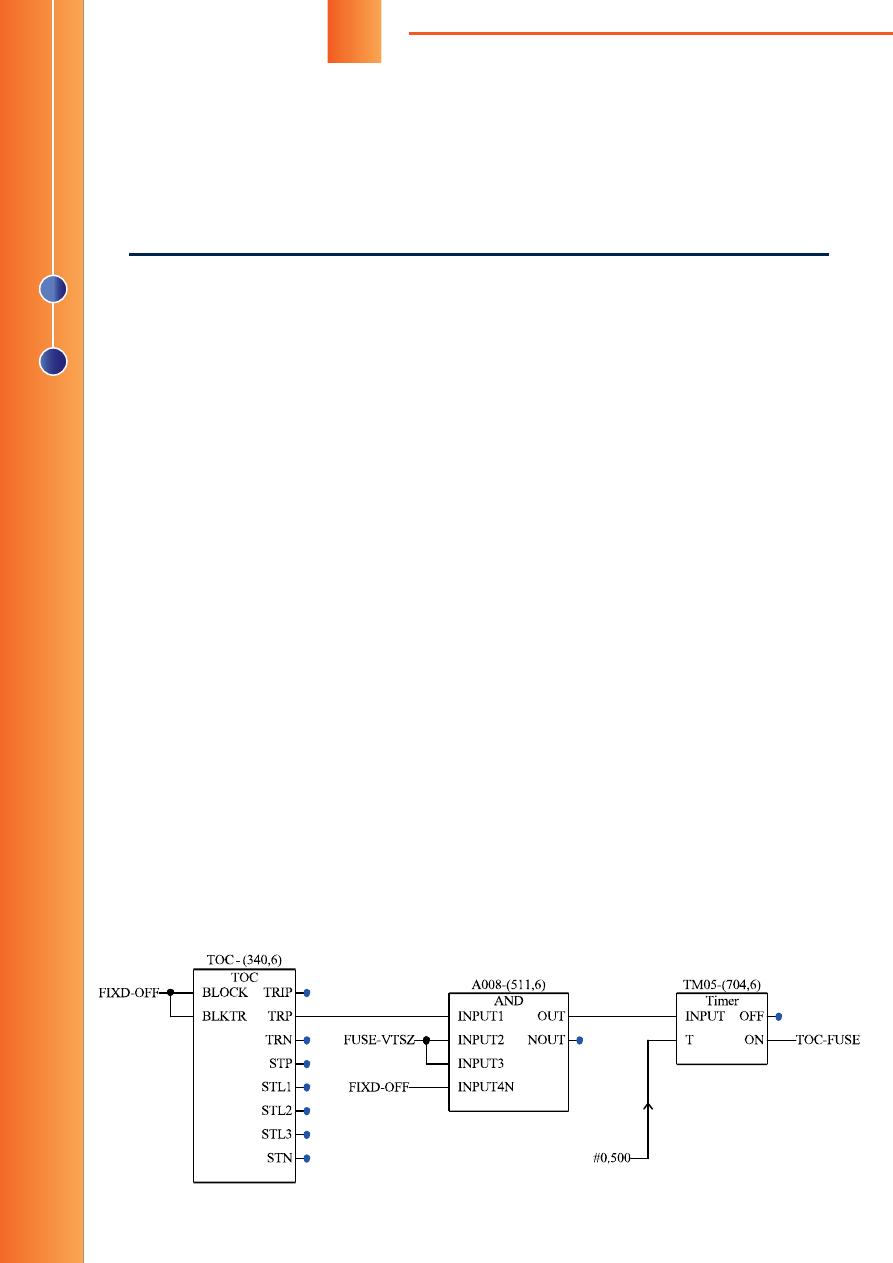
ТЕРМИНАЛЫ
СЕРИИ
«REL-511»
В
микропроцессорных
терминалах
«REL-
511»
при
возникновении
неисправности
цепей
переменного
напряжения
«
звезды
»
срабатыва
—
ет
функция
контроля
исправности
цепей
пере
—
менного
напряжения
(FUSE).
При
этом
она
бло
—
кирует
срабатывание
всех
зон
ДЗ
и
их
пуски
.
В
таком
случае
возможен
отказ
функции
ДЗ
при
возникновении
КЗ
на
ЛЭП
.
Для
отключения
междуфазных
КЗ
на
ЛЭП
,
возникающих
при
наличии
неисправности
це
—
пей
переменного
напряжения
«
звезды
»
и
,
как
следствие
,
при
заблокированной
функции
ДЗ
,
по
факту
срабатывания
функции
FUSE
автома
—
тически
вводится
резервная
МТЗ
,
выполненная
при
помощи
функции
максимальной
токовой
за
—
щиты
(
рис
. 1).
Направленность
ТЗНП
реализована
по
сдви
—
гу
вектора
тока
нулевой
последовательности
3Io
относительно
виртуального
вектора
IN>DIR,
строящегося
программно
и
отстающего
от
векто
—
ра
напряжения
нулевой
последовательности
-U4
на
угол
65° (
задаётся
уставкой
функции
ТЗНП
),
подводимого
от
цепей
напряжения
разомкнуто
—
го
треугольника
ТН
(«
Н
», «
К
»).
Если
проекция
Рис
. 1.
Резервная
МТЗ
для
терминала
«REL-511»
FUSE-VTSZ —
сигнал
неисправности
цепей
переменного
напряжения
«
звезды
»
Работа терминалов «REL-511» и
«REL-670» при неисправности
цепей переменного напряжения
При возникновении неисправности во вторичных цепях переменного напря-
жения, используемых функциями направленной токовой защиты нулевой по-
следовательности (ТЗНП) и дистанционной защиты (ДЗ) в микропроцессорных
терминалах серий «REL-511» и «REL-670» производства ООО «АББ Силовые Ав-
томатизированные Системы», возможен отказ этих защит, установленных в сети
110, 220 кВ. С учётом того, что терминалы «АBB» имеют свободно программируе-
мую логику, возможно их переконфигурирование для сохранения работоспособ-
ности функций ТЗНП и ДЗ при неисправности цепей переменного напряжения.
Ниже приведены технические решения, применяемые в ОАО «МРСК Урала».
Владислав НАУМОВ,
главный специалист отдела РЗА и ПАА ДОТиСУ
ОАО «МРСК Урала»
Page 3
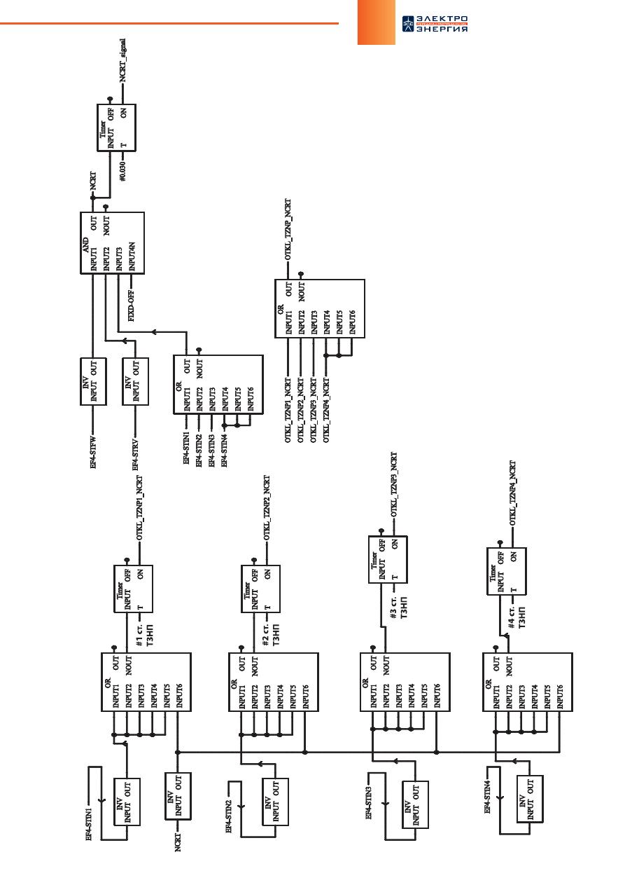
95
№
2 (29),
март
–
апрель
, 2015
95
Рис
. 2.
Резервная
ТЗНП
для
терминала
«REL-511»
EF4-STIN1 — EF4-STIN4 —
пу
ски
1—4
ст
упени
ТЗНП
;
EF4-STWF —
сигнал
пр
ямог
о
направ
ления
мощности
ну
лев
ой
после
дов
ат
ельности
;
EF4-STR
V —
сигнал
обра
тног
о
направ
ления
мощности
ну
лев
ой
после
дов
ат
ельности
.
Page 4

96
СЕТИ РОССИИ
3Io×cos(
φ
-65°)
на
отрезок
IN>DIR
превышает
по
ве
—
личине
длину
этого
отрезка
,
то
в
зависимости
от
зна
—
ка
этой
проекции
определяется
прямое
или
обратное
направление
мощности
короткого
замыкания
с
током
нулевой
последовательности
.
Цепи
переменного
напряжения
разомкнутого
тре
—
угольника
не
контролируются
функцией
FUSE.
Таким
образом
,
при
возникновении
неисправности
цепей
напряжения
разомкнутого
треугольника
и
возникно
—
вении
короткого
замыкания
с
3Io
на
ЛЭП
направлен
—
ные
ступени
функции
ТЗНП
действовать
на
отклю
—
чение
не
могут
и
срабатывают
лишь
их
пуски
,
для
которых
срабатывание
органов
мощности
нулевой
последовательности
не
требуется
.
Для
отключения
КЗ
на
ЛЭП
,
при
которых
возни
—
кают
токи
нулевой
последовательности
при
наличии
неисправности
цепей
переменного
напряжения
ра
—
зомкнутого
треугольника
,
выполнена
схема
автома
—
тического
вывода
направленности
четырёхступен
—
чатой
ТЗНП
при
неисправности
цепей
переменного
напряжения
согласно
рис
. 2.
Неисправность
цепей
напряжения
разомкнутого
треугольника
автоматиче
—
ски
выявляется
по
факту
пуска
ступени
(
ступеней
)
ТЗНП
и
отсутствия
срабатывания
органов
мощности
нулевой
последовательности
прямого
и
обратного
направления
.
При
выполнении
схемы
(
рис
. 2)
и
настройке
со
—
ответствующих
ступеням
ТЗНП
уставок
по
време
—
ни
на
четырёх
элементах
выдержки
времени
в
ло
—
гике
защит
,
вышеуказанное
КЗ
будет
отключено
ненаправленным
пуском
соответствующей
ступе
—
ни
ТЗНП
с
выдержкой
времени
,
заданной
для
этой
ступени
.
В
терминалах
серии
«REL-511»
не
представля
—
ется
возможным
выполнить
полноценный
контроль
цепи
напряжения
разомкнутого
треугольника
.
Схема
позволяет
выявлять
неисправность
цепей
напряже
—
ния
«
Н
», «
К
»
только
в
случае
возникновения
КЗ
с
током
нулевой
последовательности
3Io
достаточной
величины
для
пуска
ступеней
ТЗНП
.
При
разработке
схемы
одной
из
задач
было
ми
—
нимизировать
использование
незадействованных
логических
элементов
«
И
» («AND»)
за
счёт
исполь
—
зования
логических
элементов
отрицания
(«INV»)
и
суммирования
(«OR»),
которые
применяются
реже
при
создании
конфигурации
и
имеются
в
достаточ
—
ном
количестве
.
При
создании
логики
конфигурации
согласно
рис
. 1
и
2
необходимо
использовать
элементы
«AND»
и
«OR»
с
временем
опроса
6
мс
для
быстро
—
действующих
ступеней
ТЗНП
с
автоматическим
выводом
направленности
при
неисправности
цепи
разомкнутого
треугольника
напряжения
и
для
функ
—
ции
автоматического
ввода
междуфазной
токовой
защиты
при
неисправности
цепи
переменного
на
—
пряжения
«
звезды
».
Особое
внимание
необходимо
обратить
на
уставку
IN>DIR (
по
умолчанию
задана
30% Ib,
пре
—
дел
— 5—40% Ib)
в
параметрах
ТЗНП
терминала
«REL-511»,
которая
должна
быть
меньше
,
чем
мини
—
мальная
уставка
по
току
ступени
ТЗНП
.
ТЕРМИНАЛЫ
СЕРИИ
«REL-670»
В
отличие
от
«REL-511»,
в
терминале
«REL-670»
для
пуска
прямо
направленных
ступеней
ТЗНП
не
—
обходимо
срабатывание
органа
мощности
нулевой
последовательности
в
прямом
направлении
.
Таким
образом
,
при
неисправности
цепей
переменного
напряжения
разомкнутого
треугольника
пуски
на
—
правленных
ступеней
штатной
функции
ТЗНП
не
—
возможны
.
В
таком
случае
,
согласно
схеме
на
рис
. 3,
выполнен
автоматический
ввод
защиты
широкого
назначения
,
которая
использует
в
качестве
поляри
—
зующего
напряжения
сумму
векторов
фазных
напря
—
жений
.
Параметры
уставок
функции
широкого
назна
—
чения
задаются
в
соответствии
с
уставками
штатной
функции
ТЗНП
.
Сигналы
TEF1-STFW
и
TEF1-STRV,
использую
—
щиеся
для
определения
неисправности
цепей
на
—
пряжения
разомкнутого
треугольника
,
формируются
с
выходов
STFW
и
STRV
функции
ТЗНП
(EF4PTOC)
соответственно
.
При
исправном
состоянии
цепей
напряжения
ра
—
зомкнутого
треугольника
в
режиме
короткого
замы
—
кания
с
токами
нулевой
последовательности
пуски
и
действие
на
отключение
1
и
2
ст
.
резервной
ТЗНП
(
РТЗНП
)
заблокированы
,
и
срабатывает
штатная
функция
ТЗНП
.
Неисправность
цепей
напряжения
разомкнутого
треугольника
выявляется
автоматически
по
фак
—
ту
направленного
пуска
ступени
(
ступеней
)
ТЗНП
функции
защиты
широкого
назначения
и
отсутствия
срабатывания
органов
мощности
нулевой
после
—
довательности
штатной
функции
ТЗНП
в
обоих
на
—
правлениях
.
Сигнал
неисправности
цепей
напряжения
разом
—
кнутого
треугольника
(NCRT),
действующий
на
све
—
тодиод
с
фиксацией
,
имеет
задержку
на
срабатыва
—
ние
в
30
мс
на
программном
элементе
времени
,
так
как
сигналы
прямой
или
обратной
направленности
органа
направления
мощности
нулевой
последова
—
тельности
формируются
с
некоторой
задержкой
по
—
сле
формирования
сигнала
пуска
ступени
ТЗНП
.
При
возникновении
неисправности
цепей
напря
—
жения
разомкнутого
треугольника
и
появлении
КЗ
с
током
3Io
в
прямом
направлении
1
и
2
ст
.
РТЗНП
будут
автоматически
разблокированы
,
и
по
достиже
—
нии
заданной
выдержки
времени
произойдёт
их
на
—
правленное
действие
на
отключение
выключателя
с
пуском
УРОВ
.
Направленность
РТЗНП
обеспечива
—
ется
программным
вычислением
функцией
защиты
широкого
назначения
напряжения
нулевой
последо
—
вательности
по
фазным
напряжениям
«
звезды
».
Так
как
функция
защиты
широкого
назначения
имеет
только
две
ступени
токовой
защиты
по
пре
—
вышению
тока
,
то
их
уставки
соответствуют
устав
—
кам
первой
и
третьей
прямонаправленных
ступеней
штатной
функции
ТЗНП
.
Для
возможности
вычисления
терминалом
суммы
векторов
фазных
напряжений
,
в
конфигурации
логи
—
ки
создан
блок
предварительной
обработки
SMAI5
(
рис
. 3),
к
которому
подключены
фазные
каналы
на
—
пряжения
(CH7-CH9),
без
подключения
канала
на
—
пряжения
разомкнутого
треугольника
(CH10).
Сигнал
Page 5
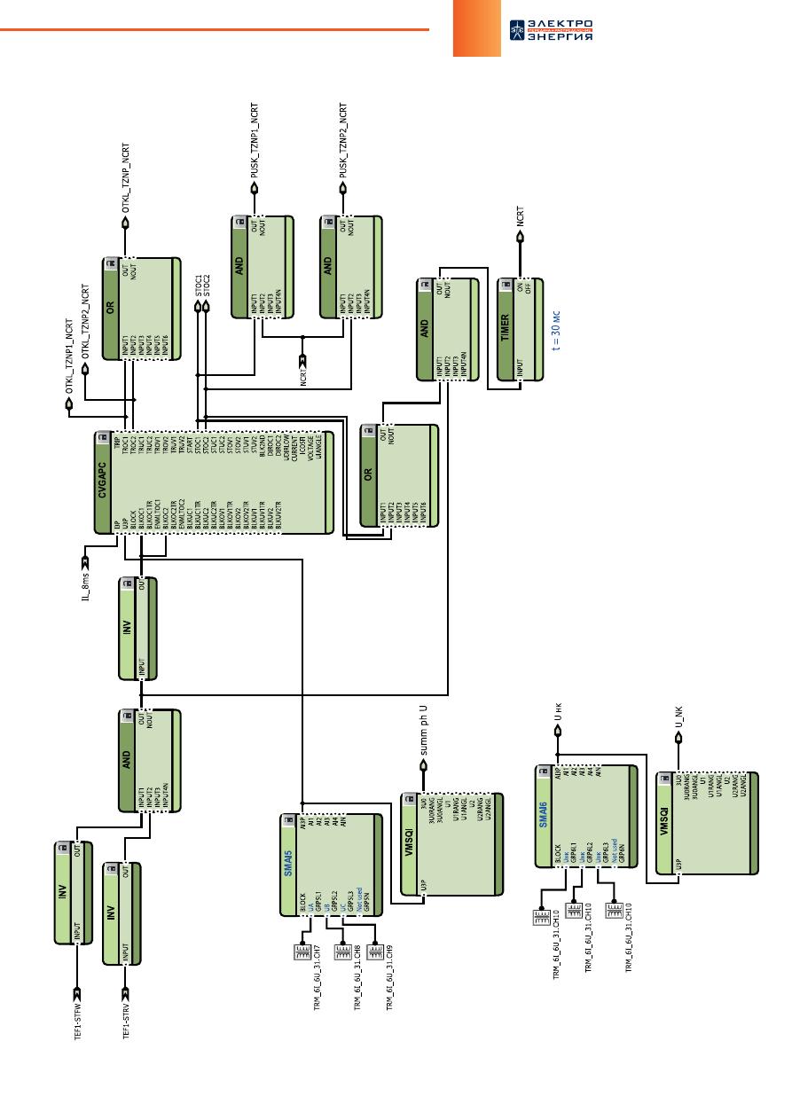
97
№
2 (29),
март
–
апрель
, 2015
Рис
. 3.
Резервная
ТЗНП
для
терминала
«REL-670»
TEF1-STFW —
сигнал
пр
ямог
о
направ
ления
мощности
ну
лев
ой
после
дов
ат
ельности
;
TEF1-STR
V —
сигнал
обра
тног
о
направ
ления
мощности
ну
лев
ой
после
дов
ат
ельности
;
OTKL_TZNP1_NCR
T
——
►
в
логик
у
отк
лю
чения
с
пу
ск
ом
УР
ОВ
;
OTKL_TZNP2_NCR
T
——
►
к
св
ет
одио
ду
;
PUSK_TZNP1_NCR
T
——
►
в
логик
у
РА
С
;
PUSK_TZNP2_NCR
T
——
►
в
логик
у
РА
С
;
OTKL_TZNP1_NCR
T
——
►
в
логик
у
РА
С
;
OTKL_TZNP2_NCR
T
——
►
в
логик
у
РА
С
;
NCR
T
——
►
к
св
ет
одио
ду
с
фик
сацией
сраб
атыв
ания
.
Page 6
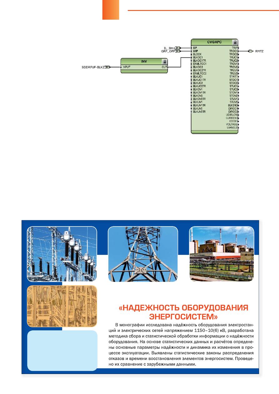
98
СЕТИ РОССИИ
с
выхода
«AI3P»
блока
SMAI5
подключён
к
вхо
—
ду
«U3P»
защиты
широ
—
кого
назначения
,
а
также
к
входу
блока
измерения
VMSQI.
На
выходе
блока
VMSQI «3U0»
в
режиме
реального
времени
будет
отображаться
величина
геометрической
суммы
фазных
напряжений
в
первичной
величине
.
Для
определения
величины
напряжения
разомк
—
нутого
треугольника
необходимо
создать
ещё
один
блок
предварительной
обработки
SMAI6,
к
трём
входам
которого
необходимо
подключить
один
и
тот
же
канал
напряжения
разомкнутого
треугольни
—
ка
(CH10).
В
режиме
реального
времени
на
выходе
блока
VMSQI «3U0»
будет
отображаться
утроенное
значение
напряжения
разомкнутого
треугольника
.
Это
значение
необходимо
разделить
на
три
.
Такое
построение
схемы
измерения
обусловлено
особен
—
ностью
работы
терминала
.
Функция
резервной
максимальной
токовой
защи
—
ты
(
РМТЗ
)
выполнена
в
функциональном
блоке
за
—
щиты
широкого
назначения
(CVGAPC).
На
вход
бло
—
ка
CVGAPC «I3P»
подключён
выходной
трёхфазный
сигнал
тока
с
выхода
блока
предварительной
обра
—
ботки
данных
SMAI (
рис
. 4).
На
вход
блока
CVGAPC
«U3P»
подключён
сигнал
«GRP_OFF»
от
блока
фик
—
сированных
сигналов
FIXD SIGN.
При
исправном
состоянии
цепей
переменного
на
—
пряжения
«
звезды
»
функция
РМТЗ
заблокирована
,
так
как
активен
вход
BLKOC1.
При
возник
—
новении
неис
—
правности
цепей
переменного
на
—
пряжения
«
звез
—
ды
»
вход
BLKOC1
становится
не
—
активным
,
и
с
момента
увели
—
чения
между
—
фазного
тока
до
уставки
срабатывания
начинает
—
ся
отсчёт
времени
внутреннего
таймера
функции
(0,5
с
),
задаваемого
уставкой
.
В
настоящее
время
в
ОАО
«
МРСК
Урала
»
в
34
терминалах
защит
ЛЭП
110, 220
кВ
серии
«REL-511»
внедрены
описанные
выше
техниче
—
ские
решения
,
обеспечивающие
работоспособность
терминалов
при
неисправности
вторичных
цепей
пе
—
ременного
напряжения
.
До
настоящего
момента
ус
—
ловий
для
срабатывания
внедрённых
схем
не
было
.
В
2015
году
в
ОАО
«
МРСК
Урала
»
планируется
продолжить
работы
по
внедрению
представленных
в
настоящей
статье
технических
решений
.
Рис
. 4.
Резервная
МТЗ
для
терминала
«REL-670»
Издательство
журнала
«
ЭЛЕКТРОЭНЕРГИЯ
.
Передача
и
распределение
»
выпустило
книгу
академика
РАЕН
,
профессора
Владимира
Абрамовича
Непомнящего
Тираж
книги
5000
экз
.,
объём
196
с
.,
формат
170
х
235
мм
.
Для
приобретения
издания
необходимо
позвонить
по
многоканальному
телефону
+7 (495) 645-12-41
или
написать
по
e-mail: [email protected]
При возникновении неисправности во вторичных цепях переменного напряжения, используемых функциями направленной токовой защиты нулевой последовательности (ТЗНП) и дистанционной защиты (ДЗ) в микропроцессорных терминалах серий «REL-511» и «REL-670» производства ООО «АББ Силовые Автоматизированные Системы», возможен отказ этих защит, установленных в сети 110, 220 кВ. С учётом того, что терминалы «АBB» имеют свободно программируемую логику, возможно их переконфигурирование для сохранения работоспособности функций ТЗНП и ДЗ при неисправности цепей переменного напряжения. Ниже приведены технические решения, применяемые в ОАО «МРСК Урала».
Релейная защита и автоматика
-
Bookmarks
Quick Links
it lilt
# IPW
IB 7.2
.
1.7
—
1
Issue C
Instructions
Overcurrent Relays
CATALOG SERIES 223
/
423
DRAWOUT SEMI — FLUSH MOUNTED
SINGLE PHASE , TWO PHASE
,
AND THREE — PHASE RELAYS
INVERSE
VERY INVERSE
EXTREMELY INVERSE
DEFINITE
TIME
.
TYPE 511
TYPE
51 Y
TYPE
51
E
TYPE
51
D
SHORT TIME
LONG TIME
LONG TIME INVERSE
.
TYPE
51
S
.
.
TYPE
51 L
TYPE
51 IM
LONG TIME VERY
INVERSE
….
TYPE
51 YM
gown
—
,
rK
‘
$
/
*
a
*
*
BBC
Brow
«
? a
cuflvi
A i !
»
SINGLE PHASE
FOR RESIDUAL GROUND PROTECTION
THREE
PHASE
FOR PHASE PROTECTION