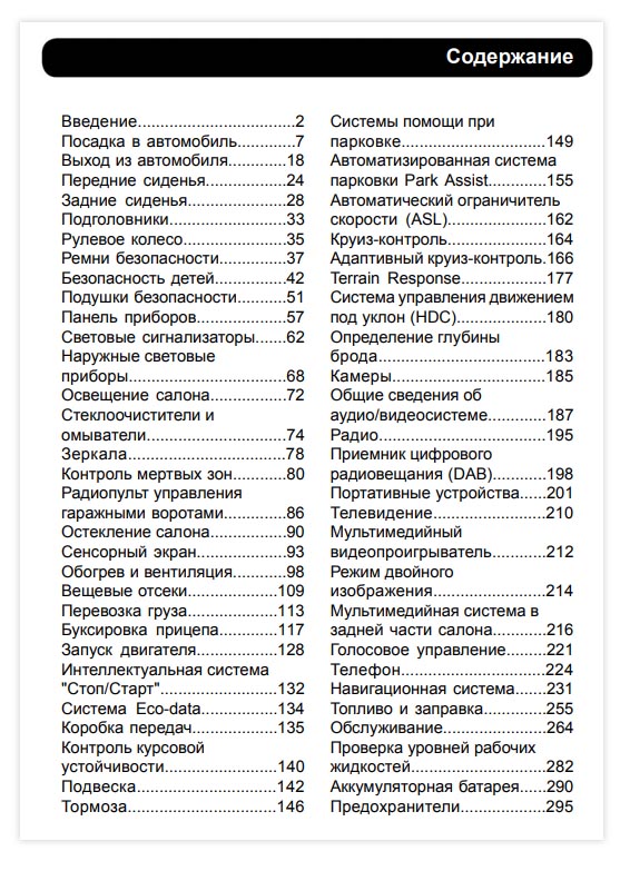
Скачать руководство по эксплуатации Range Rover Sport 2014 г.в.
К автомобилям Range Rover Sport производитель прилагает руководство по эксплуатации. Для полноценного использования всех функций транспортного средства владельцу следует детально его изучить. Кроме этого инструкция позволяет следить за состоянием автомобиля и своевременно проводить замену расходников.
Что в руководстве
Руководство по эксплуатации состоит их 65 разделов. В них производитель даёт рекомендации по безопасному использованию Рендж Ровер Спорт. Ниже перечислены несколько разделов, изучение которых позволяет водителю правильно ухаживать за автомобилем:
- Управление.В инструкции детально описываются органы управления транспортным средством или определенными функциями.
- Правила использования электронного ключа. Позволяет автовладельцу изучить систему открывания и запирания ТС.
- Настройка расположения кресел. Правильно установленные сидения снижают степень усталости водителя или пассажиров при длительных поездках.
- Изучение щитка приборов. Детально рассматривается меню приборной панели, обозначения, представленные в виде контрольных ламп и индикаторов.
- Место расположения предохранителей. Схематически обозначается, где расположен плавкий элемент и за какую часть электрооборудования он отвечает.
- Системы помощи при буксировке.
- Перечень действий для правильного запуска и остановки силового агрегата.
Контроль над уровнем технических жидкостей
Руководство по эксплуатации включает в себя инструкцию по контролю над уровнем жидкостей необходимых для работы узлов и агрегатов. Представлена схема мест расположения заливных горловин:
- Моторного масла. Место нахождения маслозаливной горловины может отличаться в зависимости от модели установленного двигателя.
- Жидкости, предназначенной для системы охлаждения силового агрегата.
- Емкости гидроусилителя руля.
- Бачка тормозной жидкости.
- Емкости стеклоомывателя.
Подробное изучение руководства по эксплуатации позволит владельцу Range Rover Sport следить за уровнем рабочих жидкостей и при необходимости вовремя обратиться к квалифицированным специалистам. Своевременная замена рабочих жидкостейпозволяет продлить срок службы узлов и агрегатов.
Скачать руководство по эксплуатации можно на сайте «Сервис Парк». Инструкцию можно сохранить в памяти гаджета. Это позволит использовать ее при необходимости вне зоны интернета.
вам ответит мастер-приёмщик
Бегун Андрей

Комментарии
4
Войдите или зарегистрируйтесь, чтобы писать комментарии, задавать вопросы и участвовать в обсуждении.
Войти
Зарегистрироваться

Saashiik
Я езжу на Volvo V50
Здравствуйте у меня не получается скачать книгу, можете помочь
10 месяцев

koto-totoro
Автор
Я езжу на Land Rover Range Rover Sport (1G)
Номер давайте, скину
10 месяцев

Nubilus
Без машины
Спасибо за полезную книгу! Я собрался уже было бумажную покупать, но решил драйв глянуть, а тут такое )))
5 лет
koto-totoro
Автор
Я езжу на Land Rover Range Rover Sport (1G)
Welcome!:)
5 лет
| Обратный звонок
Обратный звонок × Введите имя Введите телефон * |
 |
| Каталог з/ч |  |
| Расчет стоимости |  |
| Цены на работы |  |
| Акции и скидки |  |
![]()
 Адрес:
Москва, Смирновская, 19
 График работы:
Пн-Вс 9:00 — 21:00
+7 (495) 221-70-90


| О нас | Услуги и цены Land Rover | Jaguar | Акции | Модели LR |
запчасти | Контакты | Оплата

![]()
+7 (495) 221-70-90 
Москва, Смирновская, 19
Пн-Вс 9.00 — 21.00
| О нас | Услуги и цены | Jaguar | Акции | Модели LR | Запчасти | Контакты


Обратный звонок
×
Общие вопросы | Акции, Отзывные кампании, Тех.бюллетени | Устройство узлов и систем LR | RANGE ROVER 2013- | RANGE ROVER 2010-2012 | RANGE ROVER 2002-2009 | RANGE ROVER 1995-2001 | RANGE ROVER CLASSIC | RANGE ROVER SPORT 2014- | RANGE ROVER SPORT 2010-2013
| RANGE ROVER VOGUE
| RANGE ROVER DISCOVERY 2
| RANGE ROVER SPORT 05-09 | RANGE ROVER EVOQUE | DISCOVERY SPORT | DISCOVERY 4 | DISCOVERY 3 | DISCOVERY 2 | DISCOVERY 1 | FREELANDER 2 2010- | FREELANDER 2 2006-2009 | FREELANDER -2005 | DEFENDER | DEFENDER 2007-
Показать дополнительное меню
Общие вопросы
Акции, Отзывные кампании, Тех.бюллетени
Устройство узлов и систем LR
RANGE ROVER 2013-
RANGE ROVER 2010-2012
RANGE ROVER 2002-2009
RANGE ROVER 1995-2001
RANGE ROVER CLASSIC
RANGE ROVER SPORT 2014-
RANGE ROVER SPORT 2010-2013
RANGE ROVER VOGUE
RANGE ROVER DISCOVERY 2
RANGE ROVER SPORT 05-09
RANGE ROVER EVOQUE
DISCOVERY SPORT
DISCOVERY 4
DISCOVERY 3
DISCOVERY 2
DISCOVERY 1
FREELANDER 2 2010-
FREELANDER 2 2006-2009
FREELANDER -2005
DEFENDER
DEFENDER 2007-
Техническая информация
Статьи, тесты
Частые Вопросы
Файлы для скачивания
Фотогалерея
Фотогалерея RRStormer
Видео файлы
- Лэндровер
-
Файлы для скачивания RANGE ROVER SPORT 05-09
Назад
| Название | Язык | Размер файла |
|---|---|---|
|
Схема электропроводки Range Rover Sport |
10,7 МБ |
|
|
Дизельный дв-ль TDV8 и сист. управления двигателем TDV8 (2007 мод.год) (PDF) |
на русском языке |
20.3МБ |
|
Дизельный дв-ль TDV8 и сист. управления двигателем TDV8 (2007 мод.год), (Micr.Power Point) |
на русском языке |
15.7МБ |
|
Карта и периодичность планового технического обслуживания Range Rover Sport |
на русском языке |
0,6МБ |
|
Руководство по эксплуатации Range Rover Sport 2005 |
на английском языке |
18.2МБ |
|
Руководство при движении вне дорог |
на английском языке |
2.6MB |
|
Технические бюллетени и акции отзыва Range Rover Sport и Land Rover Discovery 3. Актуальность — конец 2008г. |
на русском |
9,7МБ |


Мы здесь
Москва, ул. Смирновская, д. 19
Обратный звонок
×
Введите имя
Введите телефон *
![]()
Copyright © 2001-2021 LRService.ru — Техцентр Land Rover, ремонт, обслуживание, тюнинг, запчасти для британских внедорожников в Москве. | Создание и продвижение сайтов — IMPERIA DIGITAL | Дизайн сайта — IMPERI.PRO.
4/5 | Карта сайта


Главная
Компания
Информация по моделям
Кузовной ремонт всех авто
Ремонт Jaguar
Услуги
LR-клуб
Запчасти
Вакансии
Контакты
Контакты:
Адрес: Москва, ЮВАО, ул. Смирновская, д. 19
График работы: Пн-Вс 9:00 — 21:00
 Телефон: +7 (495) 221-70-90
 Почта: Этот адрес электронной почты защищён от спам-ботов. У вас должен быть включен JavaScript для просмотра.
Обработка персональных данных
Политика конфиденциальности
Пользовательское Соглашение

Записаться на обслуживание
×
Введите имя
Введите телефон *
Записаться на ремонт
×
Введите имя
Введите телефон *
Записаться на ТО
×
Введите имя
Введите телефон *
Отправить заявку
×
Введите имя
Введите телефон *
Обратная связь
×
Введите имя
Введите телефон *
Руководство на английском языке по техническому обслуживанию и ремонту автомобиля Range Rover Sport 2005-2009 годов выпуска.
- Автор: —
- Издательство: —
- Год издания: 2005
- Страниц: —
- Формат: PDF
- Размер: 12,7 Mb

Руководство по ремонту автомобиля Range Rover Sport с 2005 года выпуска.
- Автор: —
- Издательство: Легион-Автодата
- Год издания: —
- Страниц: 606
- Формат: —
- Размер: —

Руководство по эксплуатации и техническому обслуживанию + руководства по системам навигации, телевидения и телефонной связи автомобиля Range Rover Sport 2005-2009 годов выпуска.
- Автор: —
- Издательство: Land Rover
- Год издания: 2006/2007/2008
- Страниц: 183/142/488
- Формат: PDF
- Размер: 21,2 Mb

Руководство по эксплуатации, техническому обслуживанию и ремонту автомобиля Range Rover Sport 2005-2013 годов выпуска.
- Автор: —
- Издательство: Арго-Авто
- Год издания: —
- Страниц: 800
- Формат: —
- Размер: —

General Information — About Range Rover Sport L320 Workshop Service Manual
Description and Operation Range Rover Sport L320 Workshop Manual
Introduction
This manual has been written in a format that is designed to meet the needs of technicians worldwide. The objective is to use common formats and include similar content in each manual. This manual provides general descriptions for accomplishing diagnosis and testing, service and repair work with tested and effective techniques. Following them will help to ensure reliability.
Important Safety Instructions
Appropriate service methods and correct repair procedures are essential for the safe, reliable operation of all motor vehicles as well as the personal safety of the individual carrying out the work. Anyone who departs from the instructions provided in Range Rover Sport L320 Service Manual must first establish that personal safety or vehicle integrity is not compromised by the choice of method, tools or components.
Safety Notice Range Rover Sport L320 Workshop Service Manual
Appropriate service methods and correct repair procedures are essential for the safe, reliable operation of all motor vehicles, as well as the safety of the person doing the work. This manual provides general directions for accomplishing service and repair work with tested effective techniques. Following them will help assure reliability.
There are numerous variations in procedures, techniques, tools, and parts for servicing vehicles, as well as in the skill of the person doing the work. This manual cannot possibly anticipate all such variations and provide advice or cautions as to each. Accordingly, anyone who departs from the instructions provided in the Range Rover Sport L320 Service Manual must first establish that neither personal safety or vehicle integrity is compromised from choices of methods, tools or parts.
How to use Range Rover Sport L320 Workshop Service Manual
Range Rover Sport L320 Workshop Service Manual covers all aspects necessary in order to service the vehicle effectively. The manual is structured into five main sections, General Information, Chassis, Powertrain, Electrical and Body and Paint with each section dealing with a specific part of a vehicle system. Each of the five main sections contain sub-sections dealing with items which form a part of that specific system. Pages at the start of the manual list all sections available. Each section has a contents list detailing, where applicable, Specifications, Description and Operation, Diagnosis and Testing, General Procedures and Repair
Procedures.
Where components need to be removed or disassembled in sequence, each operation in the sequence will be identified numerically and also graphically in an accompanying illustration.
Read More Range Rover Sport L320 Service Manual on PDF Below

http://www.landrovertechinfo.com/extlrprod/frmviewit.jsp?szFrom=doc&iDocCode=276785
07/16/2006 01:34 PM
Published: Mar 14, 2006
Active Stabilization System
Overview
Active stabilization is also known as dynamic response, active roll control or active cornering enhancement, and refers to
the control of the front and rear stabilizer (or anti-roll) bars.
For information on the description and operation of the system:
Active Stabilization System
Inspection and Verification
1 . Verify the customer concern.
2 . Visually inspect for obvious mechanical or electrical faults.
Mechanical
Electrical
Fluid level/condition, pipes, reservoir, etc
Pump and pulley
Drive belt condition
Hoses
Valve block
Accelerometers (correct fitment, etc)
Tire condition, pressures, etc
Suspension components (correct fitment, damage, etc)
Fuses (battery junction box)
Engine control module (ECM) relay
Harnesses/Connectors
Upper accelerometer
Lower accelerometer
Steering wheel rotation sensor
Dynamic response control module
Air suspension control module
ABS control module
Instrument cluster module
Transmission control module (TCM)
Controller area network (CAN) circuits
3 . If an obvious cause for an observed or reported concern is found, correct the cause (if possible) before proceeding to the
next step.
4 . Use the approved diagnostic system or a scan tool to retrieve any diagnostic trouble codes (DTCs) before moving onto
the symptom chart or DTC index.
Because the DTCs are stored in more than one module, a complete vehicle read is recommended
Make sure that all DTCs are cleared following rectification
Symptom chart
Symptom
Poor oncenter
response
Possible cause
System bleed
required
Stabilizer bar
bushes
Residual
pressure
Steering angle
sensor offset
Control
module
adaptive data
Action
Carry out the manual bleed procedure.
Active Stabilization System Bleeding (60.60.13) Check the stabilizer bar bushes.
Front Stabilizer Bar (60.60.50)
Rear Stabilizer Bar Check for residual pressure in the system. Check and calibrate
the steering angle sensor, clear the adaptive data after calibration.
Steering Angle Sensor (57.40.02)
http://www.landrovertechinfo.com/extlrprod/frmviewit.jsp?szFrom=doc&iDocCode=276785
Page 1 of 10
http://www.landrovertechinfo.com/extlrprod/frmviewit.jsp?szFrom=doc&iDocCode=276785
07/16/2006 01:34 PM
Asymmetrical
response
Steering angle
sensor offset
Accelerometer
calibration
System bleed
required
Check and calibrate the steering angle sensor, clear the adaptive data after
calibration.
Steering Angle Sensor (57.40.02) Calibrate the accelerometers using the approved
diagnostic system. Carry out the manual bleed procedure.
Active Stabilization System Bleeding (60.60.13)
Excessive
roll
System bleed
required
Stabilizer bar
bushes
Stabilizer bar
drop-links
Carry out the manual bleed procedure.
Active Stabilization System Bleeding (60.60.13) Check the stabilizer bar bushes and
drop links.
Front Stabilizer Bar (60.60.50)
Rear Stabilizer Bar
Powered rollrock
Harness faults
Valve block
fault
Control
Check for DTCs indicating any of the possible causes are present.
module
adaptive data
Accelerometer
fault
Stabilizer bar
drop-links
System
actuators
Oversteer or
understeer
Check the stabilizer bar drop links and the system actuators.
Front Stabilizer Bar (60.60.50)
Rear Stabilizer Bar
DTC index
NOTE:
Generic scan tools may not read the codes listed, or may read only 5-digit codes. Match the 5 digits from the scan
tool to the first 5 digits of the 7-digit code listed to identify the fault (the last 2 digits give extra information read by the
manufacturer-approved diagnostic system).
DTC
Description
Possible causes
Action
Battery
B1A8700 disconnection/control
module reset
Loss of power to
the dynamic
Check the harness and connectors, check the EMS relay,
response control
check the ground connections.
module while the
vehicle is in motion
Control lateral
C111122
acceleration
Internal control
module calculation
fault
C111127
Control lateral
acceleration
C111200 Roll angle
Check for associated codes giving more information. Refer
to the warranty policy and procedures manual if a module is
suspect.
Intermittent lower
lateral
accelerometer
signal
Check for associated codes giving more information. Carry
Lower lateral
out the accelerometer tests using the approved diagnostic
accelerometer fault system.
Internal control
module calculation
fault
Internal control
module calculation
fault
Check for associated codes giving more information. Refer
to the warranty policy and procedures manual if a module is
suspect.
http://www.landrovertechinfo.com/extlrprod/frmviewit.jsp?szFrom=doc&iDocCode=276785
Page 2 of 10
http://www.landrovertechinfo.com/extlrprod/frmviewit.jsp?szFrom=doc&iDocCode=276785
C111229 Roll angle
Off-Road
C111300
determination
C111400 Roll axis torque
C111629 Torque/Pressure
Direction control
C111729
valve(s)
C111771
C111795
Direction control
valve(s)
Direction control
valve(s)
C111909 Hydraulic pressure
C111962 Hydraulic pressure
07/16/2006 01:34 PM
Internal control
module calculation
fault
Check for associated codes giving more information. Refer
to the warranty policy and procedures manual if a module is
suspect.
Internal control
module calculation
fault
Check for associated codes giving more information. Refer
to the warranty policy and procedures manual if a module is
suspect.
Internal control
module calculation
fault
Check for associated codes giving more information. Refer
to the warranty policy and procedures manual if a module is
suspect.
Internal control
module calculation
fault
Check for associated codes giving more information. Refer
to the warranty policy and procedures manual if a module is
suspect.
Internal control
module calculation
fault
Check for associated codes giving more information. Refer
to the warranty policy and procedures manual if a module is
suspect.
Sticking direction
control valves
Install a new valve block.
Valve Block (60.60.20)
Incorrect
connection of the
pressure control
and direction
Check the valve connections and rectify as necessary.
control valves
Check the direction control valves. Check the harnesses
Damaged direction and connectors.
control valve
High resistance
harness/connectors
Low fluid
Leak in high
pressure primary
circuit
Leaking reservoir
Leak in secondary
circuit
Direction control
valves stuck open
Pressure control
valve fault
Pressure
transducer fault
Blocked filter
Actuator fault
Low fluid
Leak in high
pressure primary
circuit
Leaking reservoir
Leak in secondary
circuit
Direction control
valves stuck open
Pressure control
valve fault
Pressure
transducer fault
Blocked filter
Check and top up the fluid. Rectify leaks as necessary. For
sticking/faulty valves, install a new valve block.
Valve Block (60.60.20) For a pressure transducer fault,
install a new pressure transducer.
Valve Block Transducer (60.60.22) Install a new filter as
necessary.
Valve Block Filter (60.60.21) Check the system actuators.
Install new drop links or stabilizer bars as necessary.
Front Stabilizer Bar (60.60.50)
http://www.landrovertechinfo.com/extlrprod/frmviewit.jsp?szFrom=doc&iDocCode=276785
Page 3 of 10
http://www.landrovertechinfo.com/extlrprod/frmviewit.jsp?szFrom=doc&iDocCode=276785
Blocked filter
Actuator fault
Broken drop link
Broken stabilizer
bar
Air in system
C11197B Hydraulic pressure
Low fluid
Leak in high
pressure primary
circuit
Leaking reservoir
Leak in secondary
circuit
Blocked filter
Low pump flow
Blocked or kinked
suction hose
07/16/2006 01:34 PM
Rear Stabilizer Bar Carry out the manual bleed procedure.
Active Stabilization System Bleeding (60.60.13)
Check and top up the fluid. Rectify leaks as necessary.
Install a new filter as necessary.
Valve Block Filter (60.60.21) Check and replace the pump
as necessary.
Fluid Pump — 4.2L/4.4L (60.60.10) Check the suction hose,
rectify as necessary.
C111991 Hydraulic pressure
Pressure control
valve fault
Contaminated fluid
Kinked or blocked
return pipe
Pressure
transducer fault
Dynamic response
C1A0001
control module
Harness fault
Damaged isolation Check the control module harness. Refer to the electrical
guides.
switch
For sticking/faulty valves, install a new valve block.
Valve Block (60.60.20) Clean the system, replace the fluid.
Check and replace the return pipe as necessary. For a
pressure transducer fault, install a new pressure transducer.
Valve Block Transducer (60.60.22)
C1A0004
Dynamic response
control module
Internal control
module fault
Refer to the warranty policy and procedures manual if a
module is suspect.
C1A0043
Dynamic response
control module
Internal control
module fault
Refer to the warranty policy and procedures manual if a
module is suspect.
C1A0045
Dynamic response
control module
Internal control
module fault
Refer to the warranty policy and procedures manual if a
module is suspect.
C1A0047
Dynamic response
control module
Internal control
module fault
Refer to the warranty policy and procedures manual if a
module is suspect.
C1A0052
Dynamic response
control module
New control
module
Configure the new module using the approved diagnostic
system
C1A0054
Dynamic response
control module
New control
module
Configure the new module using the approved diagnostic
system
Pressure transducer
signal
Pressure
transducer signal
circuit: short circuit
to ground
Pressure
transducer fault
Check the pressure transducer circuit, rectify as necessary.
Install a new pressure transducer as necessary.
Valve Block Transducer (60.60.22)
Pressure transducer
signal
Pressure
transducer signal
circuit: short circuit
to power
Pressure
transducer fault
C1A0916
C1A0917
Check the pressure transducer circuit, rectify as necessary.
Install a new pressure transducer as necessary.
Valve Block Transducer (60.60.22)
http://www.landrovertechinfo.com/extlrprod/frmviewit.jsp?szFrom=doc&iDocCode=276785
Page 4 of 10
http://www.landrovertechinfo.com/extlrprod/frmviewit.jsp?szFrom=doc&iDocCode=276785
07/16/2006 01:34 PM
Pressure transducer
C1A091C
signal
Pressure control
valve circuit: short
circuit to power
Pressure control
valve fault
Pressure
transducer fault
For sticking/faulty valves, install a new valve block.
Valve Block (60.60.20) Install a new pressure transducer as
necessary.
Valve Block Transducer (60.60.22)
Pressure transducer
C1A0926
signal
Low fluid
Pressure
transducer fault
Blocked filter
Check and top up the fluid. Install a new filter as necessary.
Valve Block Filter (60.60.21) Install a new pressure
transducer as necessary.
Valve Block Transducer (60.60.22)
Damaged
accelerometers
Bent brackets
Check the accelerometers and brackets. Rectify as
necessary.
Lateral
C1A9762
accelerometer circuit
C1B0312
C1B0314
Directional control
valve 1
Directional control
valve 1 circuit:
short circuit/very
low resistance
Directional control
valve 1 circuit:
short circuit to
power
Check the directional control valve circuit. For sticking/faulty
valves, install a new valve block.
Valve Block (60.60.20)
Directional control
valve 1
Directional control
valve 1 circuit:
short circuit to
ground
Check the directional control valve circuit. Refer to the
electrical guides.
Directional control
C1B0318
valve 1
Directional control
valve 1 circuit: high Check the directional control valve circuit. Refer to the
electrical guides.
resistance
Directional control
valve 1
Directional control
valve 1 circuit: very
low resistance
Directional control Check the directional control valve circuit. Refer to the
electrical guides.
valve 1 circuit:
short circuit to
power
Directional control
C1B031D
valve 1
Directional control
valve 1 circuit: high Check the directional control valve circuit. Refer to the
electrical guides.
resistance
Hit current
C1B0400 directional control
valve 1
Directional control
valve 1 circuit: high Check the directional control valve circuit. Refer to the
electrical guides.
resistance
Hold current
C1B0500 directional control
valve 1
Directional control
valve 1 circuit: high Check the directional control valve circuit. Carry out the
manual bleed procedure.
resistance
Active Stabilization System Bleeding (60.60.13)
Air in system
Off current
C1B0600 directional control
valve 1
Directional control
valve 1 circuit:
short circuit to
other circuits
C1B0319
Check the directional control valve circuit with the control
module connector disconnected. Refer to the electrical
guides.
Directional control
http://www.landrovertechinfo.com/extlrprod/frmviewit.jsp?szFrom=doc&iDocCode=276785
Page 5 of 10
http://www.landrovertechinfo.com/extlrprod/frmviewit.jsp?szFrom=doc&iDocCode=276785
C1B0712
C1B0714
Directional control
valve 2
Directional control
valve 2
valve 2 circuit:
short circuit/very
low resistance
Directional control
valve 2 circuit:
short circuit to
power
Directional control
valve 2 circuit:
short circuit to
ground
07/16/2006 01:34 PM
Check the directional control valve circuit. For sticking/faulty
valves, install a new valve block.
Valve Block (60.60.20)
Check the directional control valve circuit. Refer to the
electrical guides.
Directional control
C1B0718
valve 2
Directional control
valve 2 circuit: high Check the directional control valve circuit. Refer to the
electrical guides.
resistance
Directional control
valve 2
Directional control
valve 2 circuit: very
low resistance
Directional control Check the directional control valve circuit. Refer to the
electrical guides.
valve 2 circuit:
short circuit to
power
C1B0719
Directional control
C1B071D
valve 2
Hit current
C1B0800 directional control
valve 2
Directional control
valve 2 circuit: high Check the directional control valve circuit. Refer to the
electrical guides.
resistance
Directional control
valve 2 circuit: high Check the directional control valve circuit. Refer to the
electrical guides.
resistance
Hold current
C1B0900 directional control
valve 2
Directional control
valve 2 circuit: high Check the directional control valve circuit. Carry out the
manual bleed procedure.
resistance
Active Stabilization System Bleeding (60.60.13)
Air in system
Off current
C1B1000 directional control
valve 2
Directional control
valve 2 circuit:
short circuit to
other circuits
Check the directional control valve circuit with the control
module connector disconnected. Refer to the electrical
guides.
C1B1112
Pressure control
valve (PCV)
PCV circuit: very
low resistance
PCV circuit: short
circuit to power
C1B1114
Pressure control
valve (PCV)
PCV circuit: short
circuit to ground
Check the PCV circuit. Refer to the electrical guides.
C1B1118
Pressure control
valve (PCV)
PCV circuit: high
resistance
Check the PCV circuit. Refer to the electrical guides.
C1B1119
Pressure control
valve (PCV)
PCV circuit: very
low resistance
PCV circuit: short
circuit to power
C1B111D
Pressure control
valve (PCV)
PCV circuit: high
resistance
Check the PCV circuit. Refer to the electrical guides.
Check the PCV circuit. Refer to the electrical guides.
Check the PCV circuit. Refer to the electrical guides.
http://www.landrovertechinfo.com/extlrprod/frmviewit.jsp?szFrom=doc&iDocCode=276785
Page 6 of 10
http://www.landrovertechinfo.com/extlrprod/frmviewit.jsp?szFrom=doc&iDocCode=276785
Low/Contaminated
fluid
PCV fault
Low flow/low
pressure pump
Pressure
transducer fault
Air in system
C1B1162
Pressure control
valve (PCV)
C1B1164
Pressure control
valve (PCV)
PCV circuit: high
resistance
Lower lateral
accelerometer circuit
Lower lateral
accelerometer
signal circuit: short
circuit to other
circuit or power
C1B1212
Lower lateral
C1B1214
accelerometer circuit
C1B1222
Lower lateral
accelerometer circuit
Lower lateral
C1B1226
accelerometer circuit
C1B1228
C1B1276
Lower lateral
accelerometer circuit
Lower lateral
accelerometer circuit
Lower lateral
accelerometer
signal circuit: short
circuit to other
circuit or ground
Lower lateral
accelerometer fault
07/16/2006 01:34 PM
Check fluid level and condition. For sticking/faulty valves,
install a new valve block.
Valve Block (60.60.20) Check the pump operation and
hoses, rectify as necessary. Install a new pressure
transducer as necessary.
Valve Block Transducer (60.60.22) Carry out the manual
bleed procedure.
Active Stabilization System Bleeding (60.60.13)
Check the PCV circuit. Refer to the electrical guides.
Check the lower lateral accelerometer circuit. Refer to the
electrical guides.
Check the lower lateral accelerometer circuit. Carry out the
accelerometer tests using the approved diagnostic system.
Install a new lower lateral accelerometer as necessary.
Lower Accelerometer (60.60.03)
Lower lateral
accelerometer
loose
Lower lateral
accelerometer
signal circuit: short
circuit to other
circuit or ground
Lower lateral
accelerometer fault
Check the lower lateral accelerometer fitment, rectify as
necessary. Check the lower lateral accelerometer circuit.
Carry out the accelerometer tests using the approved
diagnostic system. Install a new lower lateral accelerometer
as necessary.
Lower Accelerometer (60.60.03)
Lower lateral
accelerometer
signal circuit: short
circuit to other
circuit
Lower lateral
accelerometer fault
Check the lower lateral accelerometer circuit. Carry out the
accelerometer tests using the approved diagnostic system.
Install a new lower lateral accelerometer as necessary.
Lower Accelerometer (60.60.03)
Lower lateral
accelerometer
mounting damaged
Lower lateral
accelerometer
loose
Lower lateral
accelerometer fault
Check the lower lateral accelerometer fitment, rectify as
necessary. Carry out the accelerometer tests using the
approved diagnostic system. Install a new lower lateral
accelerometer as necessary.
Lower Accelerometer (60.60.03)
Lower lateral
accelerometer
mounting damaged
Lower lateral
accelerometer fault
Check the lower lateral accelerometer fitment, rectify as
necessary. Carry out the accelerometer tests using the
approved diagnostic system. Install a new lower lateral
accelerometer as necessary.
Lower Accelerometer (60.60.03)
Upper lateral
accelerometer
signal circuit: short
Check the upper accelerometer circuit. Carry out the
http://www.landrovertechinfo.com/extlrprod/frmviewit.jsp?szFrom=doc&iDocCode=276785
Page 7 of 10
http://www.landrovertechinfo.com/extlrprod/frmviewit.jsp?szFrom=doc&iDocCode=276785
Upper lateral
C1B1312
accelerometer circuit
07/16/2006 01:34 PM
signal circuit: short
accelerometer tests using the approved diagnostic system.
circuit to other
Install a new upper lateral accelerometer as necessary.
circuit or power
Upper Accelerometer (60.60.02)
Upper lateral
accelerometer fault
Upper lateral
C1B1314
accelerometer circuit
Upper lateral
accelerometer
signal circuit: short
circuit to other
circuit or ground
Upper lateral
accelerometer fault
Check the upper accelerometer circuit. Carry out the
accelerometer tests using the approved diagnostic system.
Install a new upper lateral accelerometer as necessary.
Upper Accelerometer (60.60.02)
Upper lateral
accelerometer circuit
Upper lateral
accelerometer
loose
Upper lateral
accelerometer
signal circuit: short
circuit to other
circuit
Upper lateral
accelerometer fault
Check the upper lateral accelerometer fitment, rectify as
necessary. Check the upper accelerometer circuit. Carry out
the accelerometer tests using the approved diagnostic
system. Install a new upper lateral accelerometer as
necessary.
Upper Accelerometer (60.60.02)
C1B1322
Upper lateral
C1B1326
accelerometer circuit
C1B1328
C1B1376
Upper lateral
accelerometer
signal circuit: short
circuit to other
circuit
Upper lateral
accelerometer fault
Check the upper accelerometer circuit. Carry out the
accelerometer tests using the approved diagnostic system.
Install a new upper lateral accelerometer as necessary.
Upper Accelerometer (60.60.02)
Upper lateral
accelerometer circuit
Upper lateral
accelerometer
mounting damaged
Upper lateral
accelerometer
loose
Upper lateral
accelerometer fault
Check the upper lateral accelerometer fitment, rectify as
necessary. Carry out the accelerometer tests using the
approved diagnostic system. Install a new upper lateral
accelerometer as necessary.
Upper Accelerometer (60.60.02)
Upper lateral
accelerometer circuit
Upper lateral
accelerometer
mounting damaged
Upper lateral
accelerometer fault
Check the upper lateral accelerometer fitment, rectify as
necessary. Carry out the accelerometer tests using the
approved diagnostic system. Install a new upper lateral
accelerometer as necessary.
Upper Accelerometer (60.60.02)
C1B141C Sensor supply 1
C1B151C Sensor supply 2
Lower lateral
accelerometer or
pressure
transducer supply
circuit: short circuit
to other circuit or
ground
Lower lateral
accelerometer fault
Pressure
transducer fault
Check the lower accelerometer and pressure transducer
circuits. Carry out the accelerometer tests using the
approved diagnostic system. Install a new lower lateral
accelerometer as necessary.
Lower Accelerometer (60.60.03) Install a new pressure
transducer as necessary.
Valve Block Transducer (60.60.22)
Upper lateral
accelerometer
supply circuit: short Check the upper lateral accelerometer circuits. Carry out the
accelerometer tests using the approved diagnostic system.
circuit to other
http://www.landrovertechinfo.com/extlrprod/frmviewit.jsp?szFrom=doc&iDocCode=276785
Page 8 of 10
http://www.landrovertechinfo.com/extlrprod/frmviewit.jsp?szFrom=doc&iDocCode=276785
C1B151C Sensor supply 2
Control module
C1B181C supply voltage crossreference check
P14529
Calculated torque
error
07/16/2006 01:34 PM
circuit to other
Install a new upper lateral accelerometer as necessary.
circuit or ground
Upper Accelerometer (60.60.02)
Upper lateral
accelerometer fault
Control module
supply circuit: high
resistance
Charging system
fault
Check the control module power and ground circuits. Check
for charging system DTCs, rectify as necessary.
Charging System
Internal control
module calculation
failure
Check for associated codes giving more information. Refer
to the warranty policy and procedures manual if a module is
suspect.
Control module
U007388 communication bus
off
CAN circuit fault
CAN module fault
Dynamic response
module fault
Lost communication
with the engine
U010087
control module
(ECM)
ECM CAN
message not
received in the
specified time
Lost communication
with the transmission
U010187
control module
(TCM)
TCM CAN
message not
received in the
specified time
Lost communication
with the transfer
U010287
case control module
(TCCM)
TCCM CAN
message not
received in the
specified time
Lost communication
U012287 with the anti-lock
brake (ABS) module
ABS module CAN
message not
received in the
specified time
Lost communication
with the steering
U012687
wheel rotation
sensor
Steering wheel
rotation sensor
CAN message not
received in the
specified time
Lost communication
with the air
U013287
suspension control
module
Air suspension
control module
CAN message not
received in the
specified time
Lost communication
U015587 with the instrument
cluster module
Instrument cluster
module CAN
message not
received in the
specified time
Module configuration
U030055 does not match the
vehicle configuration
Dynamic response
module incorrectly
configured
Configure the module using the approved diagnostic
system.
ECM fault
Check for CAN or module DTCs. Check the power and
U040181
Invalid data received
Communications Network
Communications Network
Communications Network
Communications Network
Communications Network
Communications Network
Communications Network
Communications Network
http://www.landrovertechinfo.com/extlrprod/frmviewit.jsp?szFrom=doc&iDocCode=276785
Page 9 of 10
http://www.landrovertechinfo.com/extlrprod/frmviewit.jsp?szFrom=doc&iDocCode=276785
U040181
from the ECM
ECM fault
07/16/2006 01:34 PM
ground circuits to the ECM, rectify as necessary.
U040281
Invalid data received
from the TCM
TCM fault
Check for CAN or module DTCs. Check the power and
ground circuits to the TCM, rectify as necessary.
U040381
Invalid data received
from the TCCM
TCCM fault
Check for CAN or module DTCs. Check the power and
ground circuits to the TCCM, rectify as necessary.
Invalid data received
U041681 from the ABS
module
ABS module fault
Check for CAN or module DTCs. Check the power and
ground circuits to the ABS module, rectify as necessary.
Invalid data received
from the air
U042181
suspension control
module
Check for CAN or module DTCs. Check the power and
Air suspension
control module fault ground circuits to the air suspension control module, rectify
as necessary.
Invalid data received
from the steering
U042881
wheel rotation
sensor
Steering wheel
rotation sensor
fault
Invalid data received
from the steering
U042885
wheel rotation
sensor
Steering wheel
rotation sensor out Calibrate the steering wheel rotation sensor using the
of calibration
approved diagnostic system. Check for CAN or module
Steering wheel
DTCs. Check the power and ground circuits to the steering
rotation sensor
wheel rotation sensor, rectify as necessary.
fault
Invalid data received
from the steering
U042886
wheel rotation
sensor
Steering wheel
rotation sensor out Calibrate the steering wheel rotation sensor using the
of calibration
approved diagnostic system. Check the wheel alignment,
Wheels out of
adjust as necessary.
alignment
Four-Wheel Alignment (57.65.04) Check for CAN or module
Steering wheel
DTCs. Check the power and ground circuits to the steering
rotation sensor
wheel rotation sensor, rectify as necessary.
fault
Check for CAN or module DTCs. Check the power and
ground circuits to the steering wheel rotation sensor, rectify
as necessary.
U1A0400
Vehicle speed CAN
signal
ABS module fault
Check for CAN or module DTCs. Check the power and
ground circuits to the ABS module, rectify as necessary.
U1A1086
Ignition status CAN
signal
Lost
communications
Check for associated codes giving more information. Refer
to the warranty policy and procedures manual if a module is
suspect.
CAN initialization
U1A1449
failure
U200798 Valve(s)
Dynamic response
module internal
fault
Refer to the warranty policy and procedures manual if a
module is suspect.
Restricted filter
Restricted high
pressure or return
line pipework
Check the filter and pipework. Check the pump, rectify as
Damaged pump
necessary. Check the fluid condition, replace and clean as
Contaminated fluid necessary. Investigate the driving profile.
Continuous use at
high lateral
acceleration
http://www.landrovertechinfo.com/extlrprod/frmviewit.jsp?szFrom=doc&iDocCode=276785
Page 10 of 10
http://www.landrovertechinfo.com/extlrprod/frmviewit.jsp?szFrom=doc&iDocCode=276785
07/16/2006 01:07 PM
Published: Feb 10, 2005
Front Stabilizer Bar (60.10.01)
Removal
1
.
WARNING: Do not work on or under a vehicle supported only by a jack. Always support the vehicle
on safety stands.
Raise and support the vehicle.
2 . Remove the wheels and tires.
3
.
CAUTION: Note the position of the hardened steel washer. The hardened steel washer must be
installed between the stabilizer bar link and the stabilizer bar. Failure to follow this instruction may result
in damage to the vehicle.
CAUTION: Use a Torx socket to prevent the ball joint rotating whilst removing the nut.
Disconnect both the stabilizer bar links from the stabilizer bar.
Remove and discard the 2 nuts.
4 . Remove the engine undershield.
For additional information, refer to Engine Undershield (76.10.50)
5 . Remove the front axle crossmember.
Remove the 4 bolts.
http://www.landrovertechinfo.com/extlrprod/frmviewit.jsp?szFrom=doc&iDocCode=276785
Page 1 of 3
http://www.landrovertechinfo.com/extlrprod/frmviewit.jsp?szFrom=doc&iDocCode=276785
07/16/2006 01:07 PM
6 . Remove the stabilizer bar bushing.
Remove the 4 nuts.
Remove the stabilizer bar clamps.
7 . Remove the stabilizer bar.
Remove the stabilizer bar out through the LH side wheel arch.
Installation
1 . Install the stabilizer bar.
Install the stabilizer bar through the LH side wheel arch.
2 . Install the stabilizer bar bushing.
Install the stabilizer bar clamps.
Tighten the nuts to 115 Nm (85 lb.ft).
3 . Install the front axle crossmember.
Tighten the 4 bolts to 115 Nm (85 lb.ft).
4 . Install the engine undershield.
For additional information, refer to Engine Undershield (76.10.50)
5
.
CAUTION: Make sure the hardened steel washer is installed between the stabilizer bar link and the
stabilizer bar. Failure to follow this instruction may result in damage to the vehicle.
http://www.landrovertechinfo.com/extlrprod/frmviewit.jsp?szFrom=doc&iDocCode=276785
Page 2 of 3
http://www.landrovertechinfo.com/extlrprod/frmviewit.jsp?szFrom=doc&iDocCode=276785
07/16/2006 01:07 PM
CAUTION: Use a Torx socket to prevent the ball joint rotating whilst installing the nut.
Connect both stabilizer bar links to the stabilizer bar.
Install new nuts and tighten to 175 Nm (129 lb.ft).
6 . Install the wheels and tires.
Tighten the wheel nuts to 140 Nm (103 lb.ft).
http://www.landrovertechinfo.com/extlrprod/frmviewit.jsp?szFrom=doc&iDocCode=276785
Page 3 of 3
http://www.landrovertechinfo.com/extlrprod/frmviewit.jsp?szFrom=doc&iDocCode=276785
07/16/2006 01:16 PM
Published: Feb 23, 2005
Specifications
Wheels
Wheel type
Wheel size
Alloy wheel
7J x 17
Alloy wheel
8J x 18
Alloy wheel
8J x 19
Alloy wheel
9J x 19
Alloy wheel
9.5J x 20
Reduced size spare wheel — Steel 5.5J x 19
CAUTION: With reduced size spare wheel installed, do not exceed 50 mph (80 kph) and replace with
standard size wheel at earliest opportunity.
CAUTION: Do not use power tools when operating the spare wheel winch, raise and lower winch manually
using hand tools only.
Tire Sizes — Standard Fit
Wheel size
Tire size
Tire load index
7J x 17 — Alloy
235/65 R17H — All terrain 108
8J x 18 — Alloy
255/55 R18V — All terrain 109
8J x 19 — Alloy
255/50 R19Y — All terrain 107
9J x 19 — Alloy
255/50 R19Y — All terrain 107
9.5J x 20 — Alloy 275/40 R20M — All terrain 106
CAUTION: Inner tubes must not be installed with any of these tires.
Tire Pressures — Not NAS Vehicles
Loading condition
bar lb/in² kPa
Normal operating conditions — Up to 4 people:
Front
2.3 34
230
Rear
2.5 36
250
Front
2.6 38
260
Rear
2.9 42
290
Reduced size spare wheel
4.2 60
420
* Standard size spare wheel
2.9 42
290
Vehicle loaded to maximum gross vehicle weight:
http://www.landrovertechinfo.com/extlrprod/frmviewit.jsp?szFrom=doc&iDocCode=276785
Page 1 of 2
http://www.landrovertechinfo.com/extlrprod/frmviewit.jsp?szFrom=doc&iDocCode=276785
07/16/2006 01:16 PM
CAUTION: * The standard size spare wheel tire should be inflated to the maximum gross vehicle weight
pressure and the pressure for the front or rear wheel locations must be adjusted accordingly if the wheel is to be
used under conditions other than with the vehicle loaded to maximum gross vehicle weight.
Tire Pressures — NAS Vehicles
Loading condition
bar lb/in² kPa
All conditions:
Front
2.6 38
260
Rear
2.9 42
290
Reduced size spare wheel
4.2 60
420
* Standard size spare wheel 2.9 42
290
CAUTION: * The standard size spare wheel tire should always be inflated to the highest loading condition
pressure which must be adjusted accordingly if the wheel is to be installed to the front wheel locations.
General Specification
Item
Make
Location
Tire low pressure sensor
Siemens On inside of wheel rim
Tire pressure sensor initiator:
Front
Siemens Attached to the fender splash shield adjacent to the front bumper
Rear
Siemens Attached to the fender splash shield adjacent to the rear bumper
Module
Siemens Attached to the roof behind the roof opening panel.
Recommended Lubricant
Application
Land Rover Part No.
Wheel hub spigot RYL 105020
Torque Specifications
Description
Nm lb-ft
* Road wheel nuts
140 103
Tire low pressure sensor 6
4
* Wheel nuts must be tightened by diagonal selection
http://www.landrovertechinfo.com/extlrprod/frmviewit.jsp?szFrom=doc&iDocCode=276785
Page 2 of 2
http://www.landrovertechinfo.com/extlrprod/frmviewit.jsp?szFrom=doc&iDocCode=276785
07/16/2006 01:40 PM
Published: Feb 9, 2005
Fluid Pump — 2.7L (TdV6) Diesel (60.60.10)
Removal
CAUTION: Dynamic Response system components are manufactured to very precise tolerances. It is
therefore essential that absolute cleanliness is observed when working with these components. Always install
blanking plugs to any open orifices or lines. Failure to follow this instruction may result in foreign matter ingress
to the dynamic response system.
1 . Disconnect the battery ground cable.
For additional information, refer to Specifications
2
.
WARNING: Do not work on or under a vehicle supported only by a jack. Always support the vehicle
on safety stands.
Raise and support the vehicle.
3 . Remove the front RH splash shield.
Remove the 4 clips.
4 . Remove the engine undershield.
For additional information, refer to Engine Undershield (76.10.50)
5 . Remove the radiator access panel.
Remove the 4 bolts.
http://www.landrovertechinfo.com/extlrprod/frmviewit.jsp?szFrom=doc&iDocCode=276785
Page 1 of 4
http://www.landrovertechinfo.com/extlrprod/frmviewit.jsp?szFrom=doc&iDocCode=276785
07/16/2006 01:40 PM
6 . Remove the front RH fender splash shield.
For additional information, refer to Fender Splash Shield (76.10.48)
7 . NOTE:
Loosen the bolts prior to removing the accessory drive belt.
Loosen the fluid pump drive pulley retaining bolts.
Loosen the 3 Torx bolts.
8 . Release the tension from the belt.
Remove the accessory drive belt.
9 . Remove the fluid pump drive pulley.
Remove the 3 bolts.
10
.
CAUTION: Before disconnecting or removing the components, ensure the area around the joint
faces and connections are clean. Plug open connections to prevent contamination.
NOTE:
Some fluid spillage is inevitable during this operation.
Disconnect the fluid pump hoses.
Clamp the fluid pump to reservoir hose.
Release the hose clip.
Disconnect the hoses.
Discard the O-ring seals.
http://www.landrovertechinfo.com/extlrprod/frmviewit.jsp?szFrom=doc&iDocCode=276785
Page 2 of 4
http://www.landrovertechinfo.com/extlrprod/frmviewit.jsp?szFrom=doc&iDocCode=276785
07/16/2006 01:40 PM
11 . Remove the fluid pump.
Remove the 3 bolts.
Installation
1 . Install the fluid pump.
Clean the locating dowels.
Install and tighten the bolts to 22 Nm (16 lb.ft).
Prime the pump with clean fluid.
2.
CAUTION: Make sure both O-ring seals are correctly installed on the high pressure union.
Connect the hoses.
Clean the component mating faces.
Lubricate and install new O-rings to the high-pressure union.
http://www.landrovertechinfo.com/extlrprod/frmviewit.jsp?szFrom=doc&iDocCode=276785
Page 3 of 4
http://www.landrovertechinfo.com/extlrprod/frmviewit.jsp?szFrom=doc&iDocCode=276785
07/16/2006 01:40 PM
Tighten the union to 35 Nm (26 lb.ft).
Install the hose clip.
Remove the hose clamp.
3 . Install the fluid pump drive pulley.
Install the Torx bolts, but do not tighten fully at this stage.
4 . Install the belt.
5 . Tighten the fluid pump drive pulley retaining bolts to 22 Nm (16 lb.ft).
6 . Install the fender splash shield.
For additional information, refer to Fender Splash Shield (76.10.48)
7 . Install the radiator access panel.
Tighten the 4 bolts to 10 Nm (7 lb.ft).
8 . Install the engine undershield.
For additional information, refer to Engine Undershield (76.10.50)
9 . Install the front RH splash shield.
10 . Refill the fluid reservoir.
11 . Connect the battery ground lead, tighten the nut to 5 Nm (4 lb.ft).
For additional information, refer to Specifications
12 . Make sure there is fluid circulation through the reservoir.
Start the engine and allow to idle.
http://www.landrovertechinfo.com/extlrprod/frmviewit.jsp?szFrom=doc&iDocCode=276785
Page 4 of 4
http://www.landrovertechinfo.com/extlrprod/frmviewit.jsp?szFrom=doc&iDocCode=276785
07/16/2006 01:35 PM
Published: Feb 28, 2005
Upper Accelerometer (60.60.02)
Special Service Tools
Accelerometer remover/replacer
204-505 (LRT-60-014A)
Removal
1 . Disconnect the battery ground cable.
For additional information, refer to Specifications
2 . Remove the front overhead console.
Carefully release the 9 clips.
Disconnect the 2 electrical connectors.
3
.
CAUTION: The accelerometer is an extremely delicate component and can easily be rendered
unserviceable. Never use an accelerometer which has been dropped or subjected to mistreatment of any
type.
Remove the upper accelerometer.
Using the special tool, release the accelerometer.
Release and disconnect the electrical connector.
http://www.landrovertechinfo.com/extlrprod/frmviewit.jsp?szFrom=doc&iDocCode=276785
Page 1 of 2
http://www.landrovertechinfo.com/extlrprod/frmviewit.jsp?szFrom=doc&iDocCode=276785
07/16/2006 01:35 PM
Installation
1 . Using the special tool, install the upper accelerometer.
Connect and secure the electrical connector.
2 . Install the front overhead console.
Connect and secure the electrical connectors.
Carefully secure the clips.
3 . Connect the battery ground cable.
For additional information, refer to Specifications
4 . Using T4, calibrate the dynamic response system.
http://www.landrovertechinfo.com/extlrprod/frmviewit.jsp?szFrom=doc&iDocCode=276785
Page 2 of 2
http://www.landrovertechinfo.com/extlrprod/frmviewit.jsp?szFrom=doc&iDocCode=276785
07/16/2006 01:23 PM
Published: Jan 5, 2005
Front Shock Absorber and Air Spring Assembly (60.21.01.99)
Removal
NOTE:
Only the air spring being removed needs to be depressurised.
1
.
WARNING: Do not work on or under a vehicle supported only by a jack. Always support the vehicle
on safety stands.
Raise and support the vehicle.
2 . Remove the fender splash shield.
For additional information, refer to Fender Splash Shield (76.10.48)
3 . Using T4, depressurize the air suspension.
For additional information, refer to Air Suspension System Depressurize and Pressurize (60.50.38)
4 . Disconnect the shock absorber and air spring assembly from the lower arm.
Remove the nut and bolt.
5 . Release the heat shield for access to the shock absorber and air spring assembly upper mounting inner nut.
Remove the nut and two bolts.
6 . Release the shock absorber and air spring assembly.
Remove the three retaining nuts.
http://www.landrovertechinfo.com/extlrprod/frmviewit.jsp?szFrom=doc&iDocCode=276785
Page 1 of 3
http://www.landrovertechinfo.com/extlrprod/frmviewit.jsp?szFrom=doc&iDocCode=276785
07/16/2006 01:23 PM
7.
CAUTION: Always plug any open connections to prevent contamination.
Release the shock absorber and air spring assembly and disconnect the air line.
8 . Remove the shock absorber and air spring assembly.
9
.
CAUTION: Visually inspect the air line ends for damage or wear. Repair or replace the air line as
necessary.
Remove the Voss connector from the air line.
Remove and discard the collet and the union.
Installation
1
.
CAUTION: Make sure the new Voss connector is installed and fully tightened with the alignment
http://www.landrovertechinfo.com/extlrprod/frmviewit.jsp?szFrom=doc&iDocCode=276785
Page 2 of 3
http://www.landrovertechinfo.com/extlrprod/frmviewit.jsp?szFrom=doc&iDocCode=276785
07/16/2006 01:23 PM
plug installed.
NOTE:
New air suspension components are supplied with new Voss connectors tightened to the correct torque. Do
not install a new voss connector if a new component is being installed.
Install a new Voss connector to the air spring.
Tighten to 3.5 Nm (2.6 lb.ft)
2 Install the shock absorber and air spring assembly.
.
Make sure the shock absorber and air spring assembly top mounting to body mating faces
are clean.
Connect the air line into the Voss connector.
Fit the nuts and tighten to 63 Nm (46 lb.ft).
Pull on the air line to make sure it is fully installed into the Voss connecter.
3 . Secure the heat shield.
Install the nut and two bolts and tighten to 10 Nm (7 lb.ft).
4 . Connect the shock absorber and air spring assembly to the lower arm.
Tighten the nut and bolt to 300 Nm (221 lb.ft).
5 . Using T4, pressurize the air suspension.
For additional information, refer to Air Suspension System Depressurize and Pressurize (60.50.38)
6 . Install the fender splash shield.
For additional information, refer to Fender Splash Shield (76.10.48)
http://www.landrovertechinfo.com/extlrprod/frmviewit.jsp?szFrom=doc&iDocCode=276785
Page 3 of 3
http://www.landrovertechinfo.com/extlrprod/frmviewit.jsp?szFrom=doc&iDocCode=276785
07/16/2006 01:25 PM
Published: Jan 6, 2005
Air Suspension Compressor Drier (60.50.09)
Removal
1
.
WARNING: Do not work on or under a vehicle supported only by a jack. Always support the vehicle
on safety stands.
Raise and support the vehicle.
2 . Remove the air suspension compressor.
For additional information, refer to Air Suspension Compressor (60.50.10)
3
.
CAUTION: Before disconnecting or removing the components, ensure the area around the joint
faces and connections are clean and dry. Plug open connections to prevent contamination.
Disconnect the air line from the air suspension compressor drier.
Release the air line from the retaining clip.
4 . NOTE:
If equipped, note the position of the air suspension compressor retaining cable.
Remove the air suspension compressor drier.
Remove the retaining screw.
Remove and discard the O-ring seal.
Installation
1 . Install a new O-ring seal.
Lubricate the O-ring with a lithium based grease.
2 NOTE:
.
If equipped, make sure the air suspension compressor retaining cable is correctly routed around the
compressor cylinder head.
Install the air suspension compressor drier.
http://www.landrovertechinfo.com/extlrprod/frmviewit.jsp?szFrom=doc&iDocCode=276785
Page 1 of 2
http://www.landrovertechinfo.com/extlrprod/frmviewit.jsp?szFrom=doc&iDocCode=276785
07/16/2006 01:25 PM
Install the retaining screw and tighten to 3 Nm (2.2 lb.ft).
3.
CAUTION: Visually inspect the air line ends for damage or wear. Replace the air line as necessary.
CAUTION: Pull on the air line to make sure it is securely intalled in the connector.
Connect the air line to the air suspension compressor drier.
Attach the air line to the retaining clip.
4 . Install the air suspension compressor.
For additional information, refer to Air Suspension Compressor (60.50.10)
http://www.landrovertechinfo.com/extlrprod/frmviewit.jsp?szFrom=doc&iDocCode=276785
Page 2 of 2
http://www.landrovertechinfo.com/extlrprod/frmviewit.jsp?szFrom=doc&iDocCode=276785
07/16/2006 01:01 PM
Published: Feb 3, 2005
Lifting
Vehicle on Wheels — Four Post Ramp
WARNING: If the drive shaft(s) are to be disconnected, it will be necessary to raise all four wheels off the
ramp in order that the shaft(s) can be rotated. If the wheel free facility is not to be used, raise the vehicle off the
ramp using suitable equipment. With the vehicle raised, position axle stands in the positions shown for the front
and rear support blocks — see illustration in Jacking. With the axle stands positioned, release the parking brake
and select NEUTRAL ‘N’ in the transmission.
WARNING: Do not push the vehicle backwards and forwards along the ramp in order to gain access to the
drive shaft fixings.
Position the vehicle on the ramp with the front and rear of the vehicle equidistant from the ends of the ramp. Chock the
wheels, select NEUTRAL in the transmission and where practicable, apply the parking brake.
Wheel Free Lift — Four Post Ramp
NOTE:
To enable the vehicle to be supported correctly on the wheel free longitudinals, it will be necessary to produce 2 off
each of the support blocks to the dimensions given in the accompanying illustrations. The supporting part of each
block must be manufactured from suitable hardwood or metal and the ‘U’ shaped base of each block must be
manufactured from metal. Note that it is essential to ensure that the ‘U’ shaped base of each block is wide enough to
fit over the wheel free longitudinals.
Front Support Block Dimensions
‘A’ = 127.0 mm (5.0 in)
‘B’ = 146.0 mm (5.75 in)
‘C’ = 89.0 mm (3.5 in)
http://www.landrovertechinfo.com/extlrprod/frmviewit.jsp?szFrom=doc&iDocCode=276785
Page 1 of 3
http://www.landrovertechinfo.com/extlrprod/frmviewit.jsp?szFrom=doc&iDocCode=276785
07/16/2006 01:01 PM
Rear support block dimensions
‘A’ = 152.0 mm (6.0 in)
‘B’ = 101.0 mm (4.0 in)
‘C’ = 76.0 mm (3.0 in)
Raising and Supporting the Vehicle
1. Position vehicle on ramp.
2. Position suspension in ‘off-road’ height.
3. Apply parking brake.
4. Raise ramp to desired height.
5. Align the wheel free longitudinals beneath the body frame longitudinals and position the support blocks beneath the
longitudinals in the positions shown.
CAUTION: Ensure that the front and rear support blocks are correctly oriented to front and rear of vehicle.
6. Engage wheel free and lower ramp slowly until weight of vehicle rests on support blocks and road wheels are just clear
of ramp.
7. Ensure that the vehicle is correctly supported on all four support blocks, that blocks are still correctly positioned and are
in full contact with the body frame longitudinals.
8. Lower the ramp.
http://www.landrovertechinfo.com/extlrprod/frmviewit.jsp?szFrom=doc&iDocCode=276785
Page 2 of 3
http://www.landrovertechinfo.com/extlrprod/frmviewit.jsp?szFrom=doc&iDocCode=276785
07/16/2006 01:01 PM
WARNING: Make sure that the vehicle is stable before commencing work.
NOTE:
Return the suspension to ‘normal ride height’ when the vehicle is removed from the ramp.
Two Post Lift
CAUTION: If the drive shaft(s) are to be removed, release the parking brake and select NEUTRAL ‘N’ in the
transmission in order that the shaft(s) can be rotated when the vehicle is raised to the desired height.
1. Position the vehicle with the centre of the lift pillars aligned approximately with the front of the driver/passenger seat
cushions.
2. Extend the lifting arms and position the pad of each lifting arm beneath the body frame longitudinal lifting points.
3. Raise the vehicle until the wheels are just clear of the ground and check that the pads of each lifting arm are still
correctly positioned.
4. Raise the vehicle to the desired height.
5. Ensure that vehicle is correctly supported on all four lifting pads, that pads are still correctly positioned and are in full
contact with the body frame longitudinals.
WARNING: Make sure that the vehicle is stable before commencing work.
http://www.landrovertechinfo.com/extlrprod/frmviewit.jsp?szFrom=doc&iDocCode=276785
Page 3 of 3
http://www.landrovertechinfo.com/extlrprod/frmviewit.jsp?szFrom=doc&iDocCode=276785
07/16/2006 01:14 PM
Published: Aug 26, 2004
Rear Stabilizer Bar Link (64.35.24)
Removal
1
.
WARNING: Do not work on or under a vehicle supported only by a jack. Always support the vehicle
on safety stands.
Raise and support the vehicle.
2 . Remove the wheel and tire.
3.
CAUTION: Use a wrench on the hexagon provided to prevent the ball joint rotating.
Remove the stabilizer bar link.
Installation
1 . Install the stabilizer bar link.
Tighten the nuts to 115 Nm (85 lb.ft).
2 . Install the wheel and tire.
Tighten the wheel nuts to 140 Nm (103 lb.ft).
http://www.landrovertechinfo.com/extlrprod/frmviewit.jsp?szFrom=doc&iDocCode=276785
Page 1 of 1
http://www.landrovertechinfo.com/extlrprod/frmviewit.jsp?szFrom=doc&iDocCode=276785
07/16/2006 01:25 PM
Published: Jul 5, 2004
Air Suspension Control Module (60.50.04)
Removal
1 . Driver side: Remove the cowl side trim panel.
For additional information, refer to Cowl Side Trim Panel (76.13.27)
2 . Remove the closing trim panel.
Release the clip.
Remove the 2 screws.
Disconnect the electrical connector.
3 . Remove the air suspension control module.
Disconnect the 4 electrical connectors.
Remove the bolt.
Release from the 2 clips.
Installation
1 . Install the air suspension control module.
http://www.landrovertechinfo.com/extlrprod/frmviewit.jsp?szFrom=doc&iDocCode=276785
Page 1 of 2
http://www.landrovertechinfo.com/extlrprod/frmviewit.jsp?szFrom=doc&iDocCode=276785
07/16/2006 01:25 PM
Secure with the clips.
Connect the electrical connectors.
Tighten the bolt to 9 Nm (7 lb.ft).
2 . Install the closing trim panel.
Connect the electrical connector.
Secure the clip.
Tighten the screws.
3 . Install the cowl side trim panel.
For additional information, refer to Cowl Side Trim Panel (76.13.27)
4 . Initiate a new control module using T4.
http://www.landrovertechinfo.com/extlrprod/frmviewit.jsp?szFrom=doc&iDocCode=276785
Page 2 of 2
http://www.landrovertechinfo.com/extlrprod/frmviewit.jsp?szFrom=doc&iDocCode=276785
07/16/2006 01:24 PM
Published: Oct 22, 2004
Air Suspension Reservoir (60.50.03)
Removal
1
.
WARNING: Do not work on or under a vehicle supported only by a jack. Always support the vehicle
on safety stands.
Raise and support the vehicle.
2 . Using T4, depressurize the air suspension.
For additional information, refer to Air Suspension System Depressurize and Pressurize (60.50.38)
3
.
CAUTION: Before the disconnection or removal of any components, ensure the area around joint
faces and connections are clean. Plug any open connections to prevent contamination.
CAUTION: The air line must only be disconnected by removal of the voss connector. Do not remove
the air line retaining boss from the air suspension reservoir. Failure to follow this instruction may result in
damage to the vehicle.
CAUTION: Visually inspect the air line ends for damage or wear. Repair or replace the air line as
necessary.
Disconnect the air line from the air suspension reservoir.
4 . Remove the air suspension reservoir.
http://www.landrovertechinfo.com/extlrprod/frmviewit.jsp?szFrom=doc&iDocCode=276785
Page 1 of 2
http://www.landrovertechinfo.com/extlrprod/frmviewit.jsp?szFrom=doc&iDocCode=276785
07/16/2006 01:24 PM
Remove the 4 bolts.
5 . Remove the Voss connector from the air line.
Remove and discard the collet and the union.
Installation
1
.
CAUTION: Make sure the new Voss connector is installed and fully tightened with the alignment
plug installed.
Install a new Voss connector to the air reservoir.
Tighten the new Voss connector to 5 Nm (4 lb.ft).
2 . Install the air suspension reservoir.
Locate the air reservoir to the chassis brackets, fit the bolts and tighten to 23 Nm (17 lb.ft).
Fully seat the air line into the Voss connector.
Pull on the air line to make sure it is fully installed into the Voss connecter.
3 . Using T4, pressurize the air suspension.
For additional information, refer to Air Suspension System Depressurize and Pressurize (60.50.38)
http://www.landrovertechinfo.com/extlrprod/frmviewit.jsp?szFrom=doc&iDocCode=276785
Page 2 of 2
http://www.landrovertechinfo.com/extlrprod/frmviewit.jsp?szFrom=doc&iDocCode=276785
07/16/2006 01:21 PM
Published: Jul 19, 2004
Air Suspension System Depressurize and Pressurize (60.50.38)
WARNING: A small amount of air pressure will be left in the air suspension system.
WARNING: Eye protection must be worn.
WARNING: Wear protective gloves.
CAUTION: Make sure tailgate, hood and all doors are closed.
CAUTION: Make sure the vehicle is in a clear working area.
1.
WARNING: The air suspension system is pressurised up to 16.8 bar (244 lbf/in²). Make sure no dirt or
grease enters the system. Always wear hand, eye and ear safety standard protection when working on the system.
Using T4, depressurize the air suspension.
2. Using T4, pressurize the air suspension.
Start and run the engine.
http://www.landrovertechinfo.com/extlrprod/frmviewit.jsp?szFrom=doc&iDocCode=276785
Page 1 of 1
http://www.landrovertechinfo.com/extlrprod/frmviewit.jsp?szFrom=doc&iDocCode=276785
07/16/2006 01:11 PM
Published: Jan 25, 2005
Rear Suspension
Rear Suspension Component Location
NOTE:
Without Dynamic Response version shown
Item Part Number
Description
1
Bolt (Upper arm forward bush)
2
Bush — Forward (Upper arm)
http://www.landrovertechinfo.com/extlrprod/frmviewit.jsp?szFrom=doc&iDocCode=276785
Page 1 of 8
http://www.landrovertechinfo.com/extlrprod/frmviewit.jsp?szFrom=doc&iDocCode=276785
3
Caged nut (Upper arm forward bush)
4
Bolt (Upper arm rearward bush)
5
Bush — Rearward (Upper arm)
6
Caged nut (Upper arm rearward bush)
7
Upper arm
8
Eccentric washer (Wheel knuckle upper ball joint)
9
Nut (Wheel knuckle upper ball joint)
10
Bolt (Wheel knuckle upper ball joint)
11
Special nut (Adjustable transverse toe link)
12
Adjustable transverse toe link
13
Washer (Adjustable transverse toe link)
14
Damper module assembly
15
Bolt (Adjustable transverse toe link)
16
Ball joint (Wheel knuckle upper)
17
Wheel knuckle and bearing assembly
18
Wheel hub
19
Ball joint (Wheel knuckle lower)
20
Circlip (Wheel knuckle lower ball joint)
21
Self-locking nut (Wheel knuckle lower ball joint)
22
Self-locking nut (Damper assembly lower attachment)
23
Bolt (Wheel knuckle lower ball joint)
24
Bolt (Damper assembly lower attachment)
25
Lower arm
26
Bush — Forward (Lower arm)
27
Self-locking nut (Lower arm forward bush)
28
Bolt (Lower arm forward bush)
29
Nut and retainer (Lower arm rearward bush)
30
Bush — Rearward (Lower arm)
31
Self-locking nut (Stabilizer bar link to lower arm)
32
Bolt (Lower arm rearward bush)
33
Stabilizer bar link
34
Self-locking nut (Stabilizer bar link to stabilizer bar)
35
Stabilizer bar bush
36
Bolt (Stabilizer bar bracket)
37
Stabilizer bar bracket
38
Stabilizer bar
07/16/2006 01:11 PM
GENERAL
The independent rear suspension offers a reduction in unsprung weight over the beam axle design. The rear suspension
comprises an upper arm, a lower arm, a wheel knuckle and wheel hub, two air spring damper modules and a stabilizer bar
and links assembly.
The rear suspension arms have been designed to give maximum ground clearance. The suspension geometery can be
adjusted for camber using a cam bolt and toe and bump steer adjustment can be corrected via an adjustable transverse
link.
AIR SUSPENSION DAMPER MODULE
http://www.landrovertechinfo.com/extlrprod/frmviewit.jsp?szFrom=doc&iDocCode=276785
Page 2 of 8
http://www.landrovertechinfo.com/extlrprod/frmviewit.jsp?szFrom=doc&iDocCode=276785
Item Part Number
07/16/2006 01:11 PM
Description
1
—
Strap*
2
—
Upper gaitor*
3
—
Self-locking nut*
4
—
Rebound washer*
5
—
O-ring — Damper rod*
6
—
Spacer — Damper rod*
7
—
Air spring*
8
—
Retaining pin — Air spring sleeve support*
9
—
Bump washer*
10
—
Spring aid*
11
—
O-ring — Air sleeve support (2 off)*
12
—
Damper rod
13
—
Damper assembly
14
—
Strap*
15
—
Lower gaitor*
16
—
Strap*
17
—
Self-locking nut (3 off)
18
—
Top mount assembly
19
—
Bush
20
—
Voss connector
NOTE:
* Shows service items
The damper module comprises an air spring assembly, top mount and a damper assembly. The damper and air spring are
only serviceable as complete assemblies.
http://www.landrovertechinfo.com/extlrprod/frmviewit.jsp?szFrom=doc&iDocCode=276785
Page 3 of 8
http://www.landrovertechinfo.com/extlrprod/frmviewit.jsp?szFrom=doc&iDocCode=276785
07/16/2006 01:11 PM
Damper
The damper assembly is a mono tube design with an air spring. The lower end of the damper is fitted with a bush and is
attached to the lower arm with a bolt and nut.
The damper functions by restricting the flow of hydraulic fluid through internal galleries within the damper. The damper rod
moves axially within the damper, its movement limited by the flow of fluid through the galleries, providing damping of
undulations in the terrain. The damper rod is sealed at its exit point from the damper body to maintain the fluid within the unit
and to prevent the ingress of dirt and moisture. The seal also incorporates a wiper to keep the rod clean.
Air Spring
The air spring is similar in design to the air spring used on the front suspension.
The air spring comprises an aluminium restraining cylinder, top mount, spring aid, air sleeve and an inner support sleeve.
The air sleeve is made from a flexible rubber material which allows the sleeve to roll up and down the air spring piston as
the vehicle changes height. The air sleeve is attached to the restraining cylinder and the support sleeve with crimp rings
which provide an air tight seal. The support sleeve contains a seal carrier which has two O-rings sealing the support sleeve
and two O-rings sealing to the damper body. The top of the air sleeve is crimped to the top mount which attaches to a
mounting on the chassis with 3 integral studs and self-locking nuts.
A spring aid is fitted to the damper rod and prevents the top mount contacting the top of the damper during full suspension
compression and assists the suspension tune. The lower end of the air spring is located over the damper body and seats on
a fabricated seat on the damper body. The air sleeve is positively attached to the seat with a retaining pin. The damper rod
is located through a central hole in the top mount. The rod is threaded at its outer end and accepts a self-locking nut which
secures the air spring to the damper rod.
The top mount is an integral part of the air spring. A bump washer is located between the top mount plate and the damper
rod. A self locking nut secures the damper rod to the top mount. The top mount attaches to a housing on the chassis with 3
integral studs and self-locking nuts. The top mount also incorporates a 6 mm Voss air fitting which allows for the attachment
of the air harness.
The air spring is fitted with two gaitors. The upper gaitor is fitted between the top mount and the air spring restraining
cylinder. The lower gaitor is secured to the lower end of the restraining cylinder and the damper body with metal straps. The
gaitors prevent dirt and debris becoming trapped between the air sleeve and the restraining cylinder.
STABILIZER BAR
http://www.landrovertechinfo.com/extlrprod/frmviewit.jsp?szFrom=doc&iDocCode=276785
Page 4 of 8
http://www.landrovertechinfo.com/extlrprod/frmviewit.jsp?szFrom=doc&iDocCode=276785
Item Part Number
07/16/2006 01:11 PM
Description
1
RH lower arm
2
Nut — link to lower arm (2 off)
3
Link (2 off)
4
Nut — link to stabilizer bar (2 off)
5
LH lower arm
6
Bush (2 off)
7
Bolt (4 off)
8
Bracket (2 off)
Vehicles without the Dynamic Response stabilizer bar system use a conventional stabilizer bar. The Dynamic Response
system is detailed in a separate section. For additional information, refer to Active Stabilization System (204-06 )
The stabilizer bar is fabricated from heat treated, 23 mm diameter solid, spring steel bar. The stabilizer bar operates, via a
pair of links, from their attachment to the lower arm.
The stabilizer bar is located on the upper face of a combined body mount and stabilizer bar bracket which is welded to each
chassis side member. The stabilizer bar is attached to the brackets with two, Teflon lined bushes. The bushes are fitted with
brackets, which are pressed onto the bushes and secured to the chassis brackets with bolts.
The stabilizer bar has crimped, ‘anti-shuffle’ collars pressed into position on the inside edges of the bushes. The collars
prevent sideways movement of the stabilizer bar.
The ends of the stabilizer bar are attached to the lower arms via links. These allow the stabilizer bar to move with the wheel
travel providing maximum effectiveness.
The rear stabilizer links are unique to vehicles with a passive (non-Dynamic Response) stabilizer bar. The passive (nonDynamic Response) links can be identified by a white colored plastic bearing moulding. The Dynamic Response rear links
are identified by a grey color plastic bearing moulding.
Each link has a ball joint at each end. The top ball joint is attached to the link at 90 degrees to the link axis. The ball joint is
located in a hole in the end of the stabilizer bar and secured with a self locking nut.
The bottom ball joint is also attached to the link at 90 degrees to the link axis. The ball joint is located a hole in a bracket on
http://www.landrovertechinfo.com/extlrprod/frmviewit.jsp?szFrom=doc&iDocCode=276785
Page 5 of 8
http://www.landrovertechinfo.com/extlrprod/frmviewit.jsp?szFrom=doc&iDocCode=276785
07/16/2006 01:11 PM
the lower arm and secured with a self-locking nut. The links are not handed and therefore can be fitted to either side of the
stabilizer bar.
UPPER ARM
Item Part Number
Description
1
Bolt
2
Bumpstop clip
3
Forward bush
4
Bumpstop clip
5
Caged nut
6
Bolt
7
Rearward bush
8
Caged nut
9
Self-locking nut — upper knuckle ball joint
10
Eccentric washer — upper knuckle ball joint
11
Cam bolt — upper knuckle ball joint
12
Upper arm
The upper arm locates in brackets on the upper surface of each chassis side member. The upper arm assembly comprises
the upper arm and two bushes. The upper arm is a pressed steel fabrication. Its outer end has two brackets with slotted
holes which locate the upper ball joint of the knuckle. The ball joint is secured in the upper arm with a cam bolt, eccentric
washer and a self-locking nut. The cam bolt and the eccentric washer allow for the adjustment of the wheel camber.
Two fabricated tubular housings provide the location for the forward and rearward bushes. The bushes, which are pressed
into the housings, locate between brackets on the chassis side members and are secured with bolts and caged nuts
through metal inserts in the centre of the bushes.
LOWER ARM
http://www.landrovertechinfo.com/extlrprod/frmviewit.jsp?szFrom=doc&iDocCode=276785
Page 6 of 8
http://www.landrovertechinfo.com/extlrprod/frmviewit.jsp?szFrom=doc&iDocCode=276785
Item Part Number
07/16/2006 01:11 PM
Description
1
Self-locking nut
2
Bumpstop clip
3
Forward bush
4
Bumpstop clip
5
Bolt
6
Nut and retainer
7
Rearward bush
8
Bolt
9
Stabilizer bar link bracket
10
Self-locking nut — damper lower attachment
11
Self-locking nut — knuckle lower ball joint attachment
12
Bolt — knuckle lower ball joint attachment
13
Bolt — damper lower attachment
14
Lower arm
The lower arm locates in brackets on the lower surface of each chassis side member. The lower arm assembly comprises
the lower arm and two bushes. The lower arm is a pressed steel fabrication. Its outer end has two brackets which locate the
lower ball joint of the knuckle. The ball joint is secured with a bolt and self-locking nut. The lower control arm also provides
for the attachment of the damper bush which is secured with a bolt and a self-locking nut.
A bracket, welded to the upper surface of the lower arm, allows for the attachment of the bottom ball joint of the stabilizer
bar link. The ball joint is secured to the bracket with a self-locking nut.
Two fabricated tubular housings provide the location for the forward and rearward bushes. The bushes, which are pressed
into the housings, locate between brackets on the chassis side members. The forward bush is secured to the chassis
bracket with a bolt and self-locking nut. The rearward bush is secured to the chassis bracket with a bolt and a nut with
retainer. The nut and retainer allows for easy installation or removal of the bolt by removing the requirement to hold the selflocking nut when installing or removing the bolt.
WHEEL KNUCKLE, WHEEL HUB AND BEARING ASSEMBLY
http://www.landrovertechinfo.com/extlrprod/frmviewit.jsp?szFrom=doc&iDocCode=276785
Page 7 of 8
http://www.landrovertechinfo.com/extlrprod/frmviewit.jsp?szFrom=doc&iDocCode=276785
Item Part Number
07/16/2006 01:11 PM
Description
1
Circlip — lower ball joint
2
Ball joint — lower
3
Park brake assembly attachment holes
4
Wheel speed sensor location
5
Wheel speed sensor cable bracket attachment
6
Ball joint — upper
7
Knuckle
8
Brake caliper attachment holes
9
Wheel bearing
10
Circlip — wheel bearing retention
11
Wheel hub
12
Nut — halfshaft
The wheel knuckle is a machined forging which is located between the upper and lower arms. The knuckle is fitted with two
ball joints which are pressed into the knuckle, with the lower ball joint being secured with a circlip. The ball joints are
positioned between brackets on the upper and lower arms and secured to the arms with a bolt and self-locking nut.
The wheel knuckle provides the location for the rear wheel taper roller bearing, which is pressed into a machined bore and
retained with a circlip. The wheel bearing is a serviceable item. The knuckle has a machined bore which provides the
location for the wheel speed sensor. Four threaded holes allow for the attachment of the park brake assembly. A cast boss
on the knuckle provides positive location for the park brake assembly. Two bosses on the knuckle casting provide the
attachment points for the rear brake caliper.
The wheel hub is a machined casting which is pressed into the wheel bearing in the knuckle. The hub has a splined centre
bore which mates with corresponding splines on the halfshaft. Five M14 studs are pressed into the wheel hub and provide
for the attachment of the road wheel with wheel nuts. Rotation of the halfshaft is passed, via the splines, to the wheel hub
which rotates on the taper roller bearing.
http://www.landrovertechinfo.com/extlrprod/frmviewit.jsp?szFrom=doc&iDocCode=276785
Page 8 of 8
http://www.landrovertechinfo.com/extlrprod/frmviewit.jsp?szFrom=doc&iDocCode=276785
07/16/2006 01:23 PM
Published: Aug 10, 2005
Front Air Shock Absorber (60.30.02.45)
Special Service Tools
Air spring tester
204-538
Removal
NOTE:
This procedure should also be used to remove the front air spring.
1 . Remove the shock absorber and spring assembly.
For additional information, refer to
2 . Remove the nut, rebound washer and rubber bushing.
Discard the nut.
3 . Remove and discard the O-ring seals and spacer.
4 . Remove the nylon retaining pin.
http://www.landrovertechinfo.com/extlrprod/frmviewit.jsp?szFrom=doc&iDocCode=276785
Page 1 of 4
http://www.landrovertechinfo.com/extlrprod/frmviewit.jsp?szFrom=doc&iDocCode=276785
07/16/2006 01:23 PM
5 Remove the air spring.
.
Using a soft faced mallet, gently tap the sleeve support upwards to release it from the O-ring
seals.
Remove and discard the 2 O-ring seals.
6 . Remove the rebound plate and spring aid.
7 . Remove the shock absorber from the vise.
Installation
1 . Install the shock absorber in the vise.
2 . Clean the components.
3 . Lubricate and install new O-rings to the seal carrier.
4 . Install the spring aid and rebound plate.
http://www.landrovertechinfo.com/extlrprod/frmviewit.jsp?szFrom=doc&iDocCode=276785
Page 2 of 4
http://www.landrovertechinfo.com/extlrprod/frmviewit.jsp?szFrom=doc&iDocCode=276785
07/16/2006 01:23 PM
5 . Install the air spring.
Align the piston with the first O-ring seal, making sure the location tag is correctly aligned.
Install the new O-ring seals and spacer, taking care not to damage the seals.
6 . Install the rubber bushing and rebound washer.
Make sure the formed insert on the bushing is located against the O-ring seal.
Install and lightly tighten the nut.
7
.
CAUTION: The air supply must be free of any moisture.
CAUTION: If during disassembly the air sleeve is unrolled, the air sleeve may inflate incorrectly (to
one side). If this occurs, release the air pressure, and insert a suitable tool that will not damage the air
sleeve or piston (a screw driver handle), into the side opposite the bulge. Inflate and deflate until the air
sleeve inflates correctly (the air sleeve will be uniform inside the shroud).
Using the special tool coupled to a tire inflator with a gauge, apply approximately 2 bar of air pressure to the air
spring to fully seat the piston over the O-ring seals.
http://www.landrovertechinfo.com/extlrprod/frmviewit.jsp?szFrom=doc&iDocCode=276785
Page 3 of 4
http://www.landrovertechinfo.com/extlrprod/frmviewit.jsp?szFrom=doc&iDocCode=276785
07/16/2006 01:23 PM
8 . Install the nylon retaining pin.
9 . Install a new nut and tighten to 98 Nm (72 lb.ft).
10 Check the assembly for leaks.
.
Inflate the module to 4 bar and check for pressure loss.
If a leak is suspected, immerse the spring and shock absorber assembly in a tank of water
to locate the source of the leak.
11 . Remove the special tool.
12 . Install the shock absorber and spring assembly.
For additional information, refer to
http://www.landrovertechinfo.com/extlrprod/frmviewit.jsp?szFrom=doc&iDocCode=276785
Page 4 of 4
http://www.landrovertechinfo.com/extlrprod/frmviewit.jsp?szFrom=doc&iDocCode=276785
07/16/2006 01:13 PM
Published: Jan 5, 2005
Rear Stabilizer Bar (64.35.08)
Removal
CAUTION: It is possible to install the stabilizer bar incorrectly. Note the position of the stabilizer bar before
removal.
1
.
WARNING: Do not work on or under a vehicle supported only by a jack. Always support the vehicle
on safety stands.
Raise and support the vehicle.
2 . Remove the rear bumper cover.
For additional information, refer to Rear Bumper Cover (76.22.74)
3 . Remove the spare wheel and tire.
4 . Raise the vehicle.
5 . Remove the rear wheels and tires.
6.
CAUTION: Use a wrench on the hexagon provided to prevent the ball joint rotating.
Release both stabilizer bar links.
Remove the 2 nuts.
7 . Remove the body mount retaining bolts.
Remove the 8 bolts.
http://www.landrovertechinfo.com/extlrprod/frmviewit.jsp?szFrom=doc&iDocCode=276785
Page 1 of 3
http://www.landrovertechinfo.com/extlrprod/frmviewit.jsp?szFrom=doc&iDocCode=276785
07/16/2006 01:13 PM
8.
CAUTION: Only raise the body sufficiently to remove the body mount.
Raise the body.
Using suitable stands, raise the body to release the body mounts.
9 . Remove the 2 rear body mounts.
10 . Remove the stabilizer bar bushing.
Remove the stabilizer bar clamps.
Remove the 4 bolts.
11 .
CAUTION: Mark the position of the stabilizer bar.
Remove the stabilizer bar.
http://www.landrovertechinfo.com/extlrprod/frmviewit.jsp?szFrom=doc&iDocCode=276785
Page 2 of 3
http://www.landrovertechinfo.com/extlrprod/frmviewit.jsp?szFrom=doc&iDocCode=276785
07/16/2006 01:13 PM
Installation
1.
CAUTION: Make sure the stabilizer bar is correctly installed.
Install the stabilizer bar.
2 . Install the stabilizer bar bushing.
3 . Install the stabilizer bar clamps.
Tighten the 4 retaining bolts to 62 Nm (46 lb.ft).
4 . Install the body mounts.
5 . Lower the body.
Remove the stands.
6 . Install the body mount retaining bolts.
Tighten the 8 retaining bolts to 133 Nm (98 lb.ft).
7 . Attach both stabilizer bar links.
Tighten the nuts to 115 Nm (85 lb.ft).
8 . Install the wheels and tires.
9 . Lower the vehicle.
10 . Install the spare wheel and tire.
11 . Install the rear bumper cover.
For additional information, refer to Rear Bumper Cover (76.22.74)
http://www.landrovertechinfo.com/extlrprod/frmviewit.jsp?szFrom=doc&iDocCode=276785
Page 3 of 3
http://www.landrovertechinfo.com/extlrprod/frmviewit.jsp?szFrom=doc&iDocCode=276785
07/16/2006 01:13 PM
Published: Jan 5, 2005
Lower Arm (64.35.54)
Removal
1
.
WARNING: Do not work on or under a vehicle supported only by a jack. Always support the vehicle
on safety stands.
Raise and support the vehicle.
2 . Remove the wheel and tire.
3.
CAUTION: Use a wrench on the hexagon provided to prevent the ball joint rotating.
Release the stabilizer bar link.
Remove and discard the retaining nut.
4 . Loosen the 2 lower arm bolts.
5 . Disconnect the shock absorber and spring assembly from the lower arm.
Remove the nut and bolt.
6 . Release the parking brake cable.
7 . Remove the 2 lower arm bolts.
8
.
CAUTION: Ensure the ball joint seal is not damaged. A damaged seal will lead to the premature
failure of the joint.
Release the knuckle from the lower arm.
Remove the bolt.
9 . Remove the lower arm.
http://www.landrovertechinfo.com/extlrprod/frmviewit.jsp?szFrom=doc&iDocCode=276785
Page 1 of 3
http://www.landrovertechinfo.com/extlrprod/frmviewit.jsp?szFrom=doc&iDocCode=276785
07/16/2006 01:13 PM
Installation
1 . Install the lower arm.
Fit the bolts but do not fully tighten at this stage.
2
.
CAUTION: Ensure the ball joint seal is not damaged. A damaged seal will lead to the premature
failure of the joint.
Connect the lower arm to the wheel knuckle.
Tighten the bolt to 175 Nm (129 lb.ft).
3 . Connect the shock absorber and spring assembly to the lower arm.
Tighten the nut and bolt to 300 Nm (221 lb.ft).
4 . Set the height, between the center of the halfshaft end and the edge of the fender trim, to 463 mm (18.23»).
5 . Tighten the lower arm bolts to 275 Nm (203 lb.ft).
6 . Secure the parking brake cable.
7 . Connect the stabilizer link.
Install a new nut and tighten to 115 Nm (85 lb.ft).
8 . Install the wheel and tire.
Tighten the wheel nuts to 140 Nm (103 lb.ft).
9 . Carry out the wheel alignment procedure.
http://www.landrovertechinfo.com/extlrprod/frmviewit.jsp?szFrom=doc&iDocCode=276785
Page 2 of 3
http://www.landrovertechinfo.com/extlrprod/frmviewit.jsp?szFrom=doc&iDocCode=276785
07/16/2006 01:13 PM
http://www.landrovertechinfo.com/extlrprod/frmviewit.jsp?szFrom=doc&iDocCode=276785
Page 3 of 3
http://www.landrovertechinfo.com/extlrprod/frmviewit.jsp?szFrom=doc&iDocCode=276785
07/16/2006 01:17 PM
Published: Mar 14, 2006
Wheels and Tires
Overview
This section will provide basic information to assist in the diagnosis of tire-related faults.
Tire pressure monitoring systems (TPMS) have been introduced on 2006 my vehicles and this section will also provide
information to assist in the diagnosis of the system.
For information on the operation of the systems:
Wheels and Tires
TPMS inspection and verification
1 . Verify the customer complaint.
NOTE:
Record any messages displayed by the system.
2 . Visually inspect for obvious mechanical or electrical faults.
Mechanical
Electrical
Tire pressures
Tire/Wheel damage
Tire low pressure sensor fitment/damage
Front antenna fitment/damage
Rear antenna fitment/damage
Module antenna fitment/damage
Fuses
Front antenna fitment/damage
Rear antenna fitment/damage
External antenna fitment/damage
TPMS switch
TPMS module
Connectors/Harnesses
3 . If an obvious cause for an observed or reported concern is found, correct the cause (if possible) before proceeding to the
next step.
4 . Use the approved diagnostic system or a scan tool to retrieve any diagnostic trouble codes (DTCs) before moving onto
the DTC index.
Make sure that all DTCs are cleared following rectification.
DTC Index
NOTE:
Generic scan tools may not read the codes listed, or may read only 5-digit codes. Match the 5 digits from the scan
tool to the first 5 digits of the 7-digit code listed to identify the fault (the last 2 digits give extra information read by the
manufacturer-approved diagnostic system).
DTC
Description
C1A0111 Switch LED status
C1A0112 Switch LED status
Possible causes
LED circuit:
short circuit to
ground
LED circuit:
short circuit to
power
Action
Check the LED and circuits. Refer to the electrical guides.
Check the LED and circuits. Refer to the electrical guides.
http://www.landrovertechinfo.com/extlrprod/frmviewit.jsp?szFrom=doc&iDocCode=276785
Page 1 of 5
http://www.landrovertechinfo.com/extlrprod/frmviewit.jsp?szFrom=doc&iDocCode=276785
C1A0113 Switch LED status
C1A2992
C1A5512
LED circuit:
high resistance
Switch activation too
long
Switch
performance
Switch
operation
Ignition switch input
circuit
Ignition switch
input circuit:
short circuit to
power
Ignition switch
input circuit:
short circuit to
ground
Ignition switch
input circuit:
high resistance
C1A5514
Ignition switch input
circuit
C1A5616
Left hand front tire low
pressure sensor
Low battery
detected
C1A5631
Left hand front tire low
pressure sensor
No signal
detected
C1A5691
Left hand front tire low
pressure sensor
Left hand front tire low
C1A5693
pressure sensor
C1A5711 Left hand front antenna
C1A5712 Left hand front antenna
C1A5713 Left hand front antenna
Data out of
range for:
pressure,
temperature or
acceleration
07/16/2006 01:17 PM
Check the LED and circuits. Refer to the electrical guides.
Check the switch operation.
Check for DTCs indicating an ignition switch fault. Check
the ignition switch and circuits. Refer to the electrical
guides.
Check the ignition switch and circuits. Refer to the electrical
guides.
Install a new tire pressure sensor.
Tire Low Pressure Sensor (74.10.05)
Check for antenna faults. If no antenna faults are indicated,
install a new tire pressure sensor.
Tire Low Pressure Sensor (74.10.05)
Install a new tire pressure sensor.
Tire Low Pressure Sensor (74.10.05)
No sensor can Check for antenna faults. If no antenna faults are indicated,
be found at this install a new tire pressure sensor.
location
Tire Low Pressure Sensor (74.10.05)
Output circuit:
short circuit to
ground
Output circuit:
short circuit to
power
Check the antenna circuits. Refer to the electrical guides.
Check the antenna circuits. Refer to the electrical guides.
Output circuit:
high resistance
Check the antenna circuits. Refer to the electrical guides.
C1A5816
Right hand front tire low
pressure sensor
Low battery
detected
Install a new tire pressure sensor.
Tire Low Pressure Sensor (74.10.05)
C1A5831
Right hand front tire low
pressure sensor
No signal
detected
Check for antenna faults. If no antenna faults are indicated,
install a new tire pressure sensor.
Tire Low Pressure Sensor (74.10.05)
C1A5891
Right hand front tire low
pressure sensor
Data out of
range for:
pressure,
temperature or
acceleration
Install a new tire pressure sensor.
Tire Low Pressure Sensor (74.10.05)
No sensor can
http://www.landrovertechinfo.com/extlrprod/frmviewit.jsp?szFrom=doc&iDocCode=276785
Page 2 of 5
http://www.landrovertechinfo.com/extlrprod/frmviewit.jsp?szFrom=doc&iDocCode=276785
07/16/2006 01:17 PM
Right hand front tire low
C1A5893
pressure sensor
No sensor can
Check for antenna faults. If no antenna faults are indicated,
be found at this install a new tire pressure sensor.
location
Tire Low Pressure Sensor (74.10.05)
C1A5911 Right hand front antenna
Output circuit:
short circuit to
ground
Check the antenna circuits. Refer to the electrical guides.
C1A5912 Right hand front antenna
Output circuit:
short circuit to
power
Check the antenna circuits. Refer to the electrical guides.
C1A5913 Right hand front antenna
C1A6016
Left hand rear tire low
pressure sensor
C1A6031
Left hand rear tire low
pressure sensor
C1A6091
Left hand rear tire low
pressure sensor
Left hand rear tire low
C1A6093
pressure sensor
C1A6111 Left hand rear antenna
C1A6112 Left hand rear antenna
C1A6113 Left hand rear antenna
Output circuit:
high resistance
Check the antenna circuits. Refer to the electrical guides.
Low battery
detected
Install a new tire pressure sensor.
Tire Low Pressure Sensor (74.10.05)
No signal
Data out of
range for:
pressure,
temperature or
acceleration
Check for antenna faults. If no antenna faults are indicated,
install a new tire pressure sensor.
Tire Low Pressure Sensor (74.10.05)
Install a new tire pressure sensor.
Tire Low Pressure Sensor (74.10.05)
No sensor can Check for antenna faults. If no antenna faults are indicated,
be found at this install a new tire pressure sensor.
location
Tire Low Pressure Sensor (74.10.05)
Output circuit:
short circuit to
ground
Output circuit:
short circuit to
power
Output circuit:
high resistance
Check the antenna circuits. Refer to the electrical guides.
Check the antenna circuits. Refer to the electrical guides.
Check the antenna circuits. Refer to the electrical guides.
C1A6216
Right hand rear tire low
pressure sensor
Low battery
detected
Install a new tire pressure sensor.
Tire Low Pressure Sensor (74.10.05)
C1A6231
Right hand rear tire low
pressure sensor
No signal
Check for antenna faults. If no antenna faults are indicated,
install a new tire pressure sensor.
Tire Low Pressure Sensor (74.10.05)
C1A6291
Right hand rear tire low
pressure sensor
Data out of
range for:
pressure,
temperature or
acceleration
Install a new tire pressure sensor.
Tire Low Pressure Sensor (74.10.05)
Right hand rear tire low
C1A6293
pressure sensor
No sensor can Check for antenna faults. If no antenna faults are indicated,
be found at this install a new tire pressure sensor.
location
Tire Low Pressure Sensor (74.10.05)
C1A6311 Right hand rear antenna
Output circuit:
short circuit to
ground
Check the antenna circuits. Refer to the electrical guides.
http://www.landrovertechinfo.com/extlrprod/frmviewit.jsp?szFrom=doc&iDocCode=276785
Page 3 of 5
http://www.landrovertechinfo.com/extlrprod/frmviewit.jsp?szFrom=doc&iDocCode=276785
C1A6312 Right hand rear antenna
C1A6313 Right hand rear antenna
Output circuit:
short circuit to
power
Check the antenna circuits. Refer to the electrical guides.
Right hand rear
antenna circuit: Check the antenna circuits. Refer to the electrical guides.
high resistance
C1A6416
Spare wheel tire low
pressure sensor
Low battery
detected
Install a new tire pressure sensor.
Tire Low Pressure Sensor (74.10.05)
C1A6491
Spare wheel tire low
pressure sensor
No signal
Install a new tire pressure sensor.
Tire Low Pressure Sensor (74.10.05)
Spare wheel tire low
C1A6493
pressure sensor
C1D1911 Module receiver
C1D1912 Module receiver
C1D1987 Module receiver
U007388
Control module
communication bus A
U014087
Lost communication with
body processor module
No sensor can If the vehicle is fitted with a temporary spare wheel and tire
be found at this take no action. Check for antenna faults. If no antenna
faults are indicated, install a new tire pressure sensor.
location
Tire Low Pressure Sensor (74.10.05)
Receiver data
circuit: short
Check the receiver circuits. Refer to the electrical guides.
circuit to ground
Receiver data
circuit: short
Check the receiver circuits. Refer to the electrical guides.
circuit to power
Receiver data
circuit: missing
message
CAN bus off
Check the receiver circuits. Refer to the electrical guides.
Communications Network
Missing
message
Communications Network
Lost communication with
U015587 instrument cluster
module
Missing
message
Communications Network
Lost communication with
U016487 heating ventilation and
air conditioning module
Missing
message
Communications Network
U030055
Internal control module
incompatibility
U041600 Invalid data received
U1A1449 CAN initialization failure
07/16/2006 01:17 PM
Not configured
Invalid data
received from
vehicle
dynamics
control module
Internal
electronic
failure
Configure the module using the approved diagnostic
system.
Communications Network
Communications Network
Wheels and tires inspection and verification
For basic information on the wheels and tires available for this model year.
Wheels and Tires
http://www.landrovertechinfo.com/extlrprod/frmviewit.jsp?szFrom=doc&iDocCode=276785
Page 4 of 5
http://www.landrovertechinfo.com/extlrprod/frmviewit.jsp?szFrom=doc&iDocCode=276785
07/16/2006 01:17 PM
For specifications for the wheels and tires (pressures, torques, etc).
Specifications
When replacing wheels or tires you must comply with local legislation regarding health and safety and correct fitment.
If the vehicle is fitted with TPMS, only approved wheels and tires should be used. If the wheel and tire size is changed (for
example from R18 to R20) the TPMS module should be updated with the correct pressure information appropriate to the
new wheel and tire set. Update the TPMS module using the approved diagnostic system.
As a general guideline, only replace tires in pairs or as a set, and only with tires of equivalent size and specification.
Confirm the symptoms of the customer complaint.
As much information as possible should be gathered from the driver to assist in diagnosing the cause(s).
1 . Before a road test, carry out a basic inspection to make sure the vehicle is safe and legal to drive.
Basic inspection
Correct tire inflation.
Specifications
Legal tire tread depth.
Cuts/Bulges in tire sidewall(s).
Tire ply separation.
Embedded objects.
Wheel rim damage.
Correct tire fitment (specification, direction of rotation, etc).
Any obvious distortion of the tire (flat/high spots).
Worn/Damaged steering or suspension components.
Front Suspension
Rear Suspension
Road test
If the results of the basic inspection are acceptable, carry out a road test to confirm the symptoms.
To reproduce the symptoms, test the vehicle on similar roads to those on which the fault occurs and at similar speeds
(provided it is legal to do so).
If the vibration or noise can be reproduced, note the speed at which it occurs and see if it is possible to drive through the
symptom, meaning, is it possible to alter the fault by driving faster or slower than the speed at which it occurs?
If it is possible, it is likely that the fault is caused by an imbalance in the wheel or tire.
If the vibration or noise gets worse as the vehicle speed increases, it is likely that the fault is caused by distortion in the
wheel or tire, or worn or damaged components.
Distortion checks
Check for distortion by raising the vehicle so that the wheels are free and placing an axle stand or similar fixed object next
to each wheel in turn.
If the stand is placed at the tread of the tire, the tire can be checked for ovality by turning the wheel by hand and checking
for high or low spots where the gap between the tread and the stand increases or reduces.
If the stand is placed next to the wheel rim or tire sidewall, the wheel and tire can be checked for run-out in a similar way.
http://www.landrovertechinfo.com/extlrprod/frmviewit.jsp?szFrom=doc&iDocCode=276785
Page 5 of 5
http://www.landrovertechinfo.com/extlrprod/frmviewit.jsp?szFrom=doc&iDocCode=276785
07/16/2006 01:27 PM
Published: Feb 25, 2005
Rear Air Shock Absorber (64.30.02.45)
Special Service Tools
Air spring tester
204-538
Band-it Thrift tool
100-050 (LRT-99-019)
Removal
NOTE:
This procedure should also be used to remove the rear air spring.
1
.
WARNING: Do not work on or under a vehicle supported only by a jack. Always support the vehicle
on safety stands.
Raise and support the vehicle.
2 . Remove the wheel and tire.
3 . Remove the shock absorber and spring assembly.
For additional information, refer to Rear Shock Absorber and Air Spring Assembly (64.21.01.99)
4 . Remove the gaiter.
Remove and discard the 2 straps.
http://www.landrovertechinfo.com/extlrprod/frmviewit.jsp?szFrom=doc&iDocCode=276785
Page 1 of 5
http://www.landrovertechinfo.com/extlrprod/frmviewit.jsp?szFrom=doc&iDocCode=276785
07/16/2006 01:27 PM
5 . Remove the nut, rebound washer and rubber bushing.
Discard the nut.
6 . Remove and discard the O-ring seals and spacer.
7 . Remove the nylon retaining pin.
8 . Remove the rebound plate and spring aid.
http://www.landrovertechinfo.com/extlrprod/frmviewit.jsp?szFrom=doc&iDocCode=276785
Page 2 of 5
http://www.landrovertechinfo.com/extlrprod/frmviewit.jsp?szFrom=doc&iDocCode=276785
07/16/2006 01:27 PM
9 Remove the air spring.
.
Using a soft faced mallet, gently tap the sleeve support upwards to release it from the O-ring
seals.
Remove and discard the 2 O-ring seals.
10 . Remove the shock absorber from the vise.
Installation
1 . Install the shock absorber in the vise.
2 . Clean the components.
3 . Lubricate and install new O-rings to the seal carrier.
4 . Install the spring aid and rebound plate.
5 . Install the air spring.
Align the piston with the first O-ring seal, making sure the location tag is correctly aligned.
http://www.landrovertechinfo.com/extlrprod/frmviewit.jsp?szFrom=doc&iDocCode=276785
Page 3 of 5
http://www.landrovertechinfo.com/extlrprod/frmviewit.jsp?szFrom=doc&iDocCode=276785
07/16/2006 01:27 PM
6 . Install the new O-ring seals and spacer, taking care not to damage the seals.
7 . Install the rubber bushing and rebound washer.
Make sure the formed insert on the bushing is located against the O-ring seal.
8 . Install and lightly tighten the nut.
9
.
CAUTION: The air supply must be free of any moisture.
CAUTION: If during disassembly the air sleeve is unrolled, the air sleeve may inflate incorrectly (to
one side). If this occurs, release the air pressure, and insert a suitable tool that will not damage the air
sleeve or piston (a screw driver handle), into the side opposite the bulge. Inflate and deflate until the air
sleeve inflates correctly (the air sleeve will be uniform inside the shroud).
Install the air spring piston over the O-ring seals.
Using the special tool coupled to a tire inflator with a gauge, apply approximately 2 bar of air
pressure to the air spring to fully seat the piston over the O-ring seals.
10 . Tighten the top nut to 98 Nm (72 lb.ft).
11 Check the assembly for leaks.
.
Inflate the module to 4 bar and check for pressure loss.
If a leak is suspected, immerse the spring and shock absorber assembly in a tank of water
to locate the source of the leak.
12 . Install the gaiter.
Using the special tool, install new straps.
http://www.landrovertechinfo.com/extlrprod/frmviewit.jsp?szFrom=doc&iDocCode=276785
Page 4 of 5
http://www.landrovertechinfo.com/extlrprod/frmviewit.jsp?szFrom=doc&iDocCode=276785
07/16/2006 01:27 PM
13 . Install the shock absorber and spring assembly.
For additional information, refer to Rear Shock Absorber and Air Spring Assembly (64.21.01.99)
http://www.landrovertechinfo.com/extlrprod/frmviewit.jsp?szFrom=doc&iDocCode=276785
Page 5 of 5
http://www.landrovertechinfo.com/extlrprod/frmviewit.jsp?szFrom=doc&iDocCode=276785
07/16/2006 01:21 PM
Published: Oct 17, 2005
Ride Height Adjustments (60.90.03)
Special Service Tools
Wheel Adaptor — Ride Height
204-557/1
Wheel Adaptor Boss — Ride Height
204-557/2
Front Adapter — Ride Height
204-557/3B
Rear Adaptor — Ride Height
204-557/4
Scale — Ride Height
204-557/5
http://www.landrovertechinfo.com/extlrprod/frmviewit.jsp?szFrom=doc&iDocCode=276785
Page 1 of 5
http://www.landrovertechinfo.com/extlrprod/frmviewit.jsp?szFrom=doc&iDocCode=276785
07/16/2006 01:21 PM
Scale Extension — Long — Ride Height
204-557/6
Scale Extension — Short — Ride Height
204-557/7
CAUTION: Make sure the wheels and tires, tie rod ends, suspension joints and wheel bearings are free
from damage, wear and free play.
CAUTION: Make sure the tire pressures are within specification.
CAUTION: Make sure there are no heavy objects in the vehicle.
CAUTION: The ride height must be measured with the vehicle weight supported by the suspension.
CAUTION: With the engine running and all vehicle doors closed, make sure the air suspension is
functioning and the vehicle height can be raised and lowered using the air suspension switch.
CAUTION: Drive the vehicle on to a flat, level surface.
CAUTION: Make sure the steering is in the straight ahead position.
NOTE:
This procedure must be carried out after replacement of the air suspension control module or height sensor link arm,
removal or replacement of the front or rear upper arms or the height sensor. The ride height must also be checked
and adjusted when the wheel alignment is adjusted. The ride height does not need calibration after removal or
replacement of the front or rear air springs or shock absorbers.
1. Check the tie rod ends, suspension joints, wheel bearings and wheels and tires for damage, wear and free play.
Adjust or repair any worn, damaged or incorrectly adjusted components.
http://www.landrovertechinfo.com/extlrprod/frmviewit.jsp?szFrom=doc&iDocCode=276785
Page 2 of 5
http://www.landrovertechinfo.com/extlrprod/frmviewit.jsp?szFrom=doc&iDocCode=276785
07/16/2006 01:21 PM
2. Check and adjust tire pressures.
3.
CAUTION: Set the ride height to NORMAL and wait until the system stops adjusting. This is indicated by the
NORMAL height symbol on the air suspension switch being illuminated and all other symbols being extinguished.
Set the air suspension ride height switch to NORMAL position.
4.
CAUTION: The ride height measurements are made between the vehicle lower suspension arm fixings and
the flat, level surface. If the ride height calibration procedure is carried out on a vehicle lift, the measurements
must be made to a position at the same level as the vehicle lift platform.
Position the vehicle on a calibrated, level surface.
5. Connect T4 to the vehicle.
6.
CAUTION: Make sure the vehicle is not moved once it has been positioned to take measurements.
Start and run the engine for a minimum of three minutes.
7. When instructed by T4, use the special tool to measure and record the height setting from each wheel center to the
calibrated level surface.
http://www.landrovertechinfo.com/extlrprod/frmviewit.jsp?szFrom=doc&iDocCode=276785
Page 3 of 5
http://www.landrovertechinfo.com/extlrprod/frmviewit.jsp?szFrom=doc&iDocCode=276785
07/16/2006 01:21 PM
8. Using the special tool, measure and record the height setting from each front lower arm front bolt head to the calibrated
level surface.
9. Using the special tool, measure and record the height setting from each rear lower arm rear bolt head to the calibrated
level surface.
10.
CAUTION: T4 will now cause the vehicle height to change.
Using T4, load the new ride height calibration to the vehicle.
http://www.landrovertechinfo.com/extlrprod/frmviewit.jsp?szFrom=doc&iDocCode=276785
Page 4 of 5
http://www.landrovertechinfo.com/extlrprod/frmviewit.jsp?szFrom=doc&iDocCode=276785
07/16/2006 01:21 PM
11. When instructed by T4, use the special tools to repeat the vehicle ride height measurments.
12. If necessary, re-calibrate the vehicle ride height.
http://www.landrovertechinfo.com/extlrprod/frmviewit.jsp?szFrom=doc&iDocCode=276785
Page 5 of 5
http://www.landrovertechinfo.com/extlrprod/frmviewit.jsp?szFrom=doc&iDocCode=276785
07/16/2006 01:44 PM
Published: Jan 6, 2005
Rear Stabilizer Bar Bushing
Removal
1
.
WARNING: Do not work on or under a vehicle supported only by a jack. Always support the vehicle
on safety stands.
Raise and support the vehicle.
2 . Remove the rear bumper cover.
For additional information, refer to Rear Bumper Cover (76.22.74)
3 . Remove the spare wheel and tire.
4 . Raise the vehicle.
5 . Remove the rear wheels and tires.
6 . Remove the body mount retaining bolts.
Remove the 8 bolts.
7.
CAUTION: Only raise the body sufficiently to remove the body mounts.
Raise the body.
Using suitable stands, raise the body to release the body mounts.
8 . Remove the 2 rear body mounts.
http://www.landrovertechinfo.com/extlrprod/frmviewit.jsp?szFrom=doc&iDocCode=276785
Page 1 of 2
http://www.landrovertechinfo.com/extlrprod/frmviewit.jsp?szFrom=doc&iDocCode=276785
07/16/2006 01:44 PM
9 . Remove the stabilizer bar bushings.
Remove the 4 bolts.
Remove the 2 clamps.
Installation
1 . Install the stabilizer bar bushings.
2 . Install the stabilizer bar clamps.
Tighten the 4 retaining bolts to 62 Nm (46 lb.ft).
3 . Install the body mounts.
4 . Lower the body.
Remove the stands.
5 . Install the body mount retaining bolts.
Tighten the 8 retaining bolts to 133 Nm (98 lb.ft).
6 . Install the wheels and tires.
7 . Lower the vehicle.
8 . Install the spare wheel and tire.
9 . Install the rear bumper cover.
For additional information, refer to Rear Bumper Cover (76.22.74)
http://www.landrovertechinfo.com/extlrprod/frmviewit.jsp?szFrom=doc&iDocCode=276785
Page 2 of 2
http://www.landrovertechinfo.com/extlrprod/frmviewit.jsp?szFrom=doc&iDocCode=276785
07/16/2006 01:45 PM
Published: Jan 6, 2005
Front Stabilizer Bar (60.60.50)
Removal
CAUTION: Dynamic Response system components are manufactured to very precise tolerances. It is
therefore essential that absolute cleanliness is observed when working with these components. Always install
blanking plugs to any open orifices or lines. Failure to follow this instruction may result in foreign matter ingress
to the Dynamic Response system.
1
.
WARNING: Do not work on or under a vehicle supported only by a jack. Always support the vehicle
on safety stands.
Raise and support the vehicle.
2 . Remove the front wheels and tires.
3 . Remove the front driveshaft.
For additional information, refer to Front Driveshaft — 4.2L, Vehicles With: Supercharger (47.15.02)
4
.
CAUTION: Before disconnecting or removing the components, ensure the area around the joint
faces and connections are clean. Plug open connections to prevent contamination.
CAUTION: Make sure the actuator fluid lines are not damaged or kinked during removal or
installation.
NOTE:
Some fluid spillage is inevitable during this operation.
Disconnect the fluid lines from the actuator.
Position container to collect fluid loss.
Remove the 2 bolts.
Remove and discard the O-ring seals.
Remove and discard the plastic spacer washers.
Install blanking caps to the exposed ports.
http://www.landrovertechinfo.com/extlrprod/frmviewit.jsp?szFrom=doc&iDocCode=276785
Page 1 of 4
http://www.landrovertechinfo.com/extlrprod/frmviewit.jsp?szFrom=doc&iDocCode=276785
5
.
07/16/2006 01:45 PM
CAUTION: Note the position of the hardened steel washer. The hardened steel washer must be
installed between the stabilizer bar link and the stabilizer bar. Failure to follow this instruction may result
in damage to the vehicle.
CAUTION: Use a Torx socket to prevent the ball joint rotating whilst removing the nut.
Disconnect both the stabilizer bar links from the stabilizer bar.
Remove and discard the 2 nuts.
6 . NOTE:
Left-hand shown, right-hand similar.
Remove the stabilizer bar bushings.
Remove the 6 bolts.
Remove the stabilizer bar clamps.
http://www.landrovertechinfo.com/extlrprod/frmviewit.jsp?szFrom=doc&iDocCode=276785
Page 2 of 4
http://www.landrovertechinfo.com/extlrprod/frmviewit.jsp?szFrom=doc&iDocCode=276785
7
.
07/16/2006 01:45 PM
CAUTION: Make sure the actuator bleed nipple is not damaged when removing or installing the LH
stabilizer bar.
Remove the LH stabilizer bar from the Dynamic Response actuator.
Remove and discard the 6 bolts.
8 . Remove the RH stabilizer bar and Dynamic Response actuator assembly.
Installation
1 . Install the RH stabilizer bar and Dynamic Response actuator assembly.
2
.
CAUTION: Make sure the actuator bleed nipple is not damaged when removing or installing the LH
stabilizer bar.
Install the LH stabilizer bar to the Dynamic Response actuator.
Clean the component mating faces.
Install 6 new bolts and tighten to 120 Nm (89 lb.ft).
3 . Install the stabilizer bar bushings.
Clean the components.
Install the stabilizer bar clamps.
Install the 6 bolts.
Tighten the bolts to 115 Nm (85 lb.ft).
4
.
CAUTION: Make sure the hardened steel washer is installed between the stabilizer bar link and the
stabilizer bar. Failure to follow this instruction may result in damage to the vehicle.
CAUTION: Use a Torx socket to prevent the ball joint rotating whilst installing the nut.
Connect the LH stabilizer bar link.
Install a new nut and tighten to 175 Nm (129 lb.ft).
5
http://www.landrovertechinfo.com/extlrprod/frmviewit.jsp?szFrom=doc&iDocCode=276785
Page 3 of 4
http://www.landrovertechinfo.com/extlrprod/frmviewit.jsp?szFrom=doc&iDocCode=276785
5
.
07/16/2006 01:45 PM
CAUTION: Make sure the actuator fluid lines are not damaged or kinked during removal or
installation.
CAUTION: Care must be taken to avoid damage to the plastic spacer washers and O-ring seals
during installation of the fluid lines to the actautor.
NOTE:
Some fluid spillage is inevitable during this operation.
Connect the fluid lines to the actuator.
Clean the component mating faces.
Remove the blanking caps from the ports.
Install new plastic spacer washers and O-ring seals.
Tighten the 2 bolts to 22 Nm (16 lb.ft).
6 . Bleed the front of the Dynamic Response system using T4.
7
.
CAUTION: Make sure the hardened steel washer is installed between the stabilizer bar link and the
stabilizer bar. Failure to follow this instruction may result in damage to the vehicle.
CAUTION: Use a Torx socket to prevent the ball joint rotating whilst installing the nut.
Connect the RH stabilizer bar link.
Install a new nut and tighten to 175 Nm (129 lb.ft).
8 . Install the front driveshaft.
For additional information, refer to Front Driveshaft — 4.2L, Vehicles With: Supercharger (47.15.02)
9 . Install the front wheels and tires.
Tighten the wheel nuts to 140 Nm (103 lb.ft).
http://www.landrovertechinfo.com/extlrprod/frmviewit.jsp?szFrom=doc&iDocCode=276785
Page 4 of 4
http://www.landrovertechinfo.com/extlrprod/frmviewit.jsp?szFrom=doc&iDocCode=276785
07/16/2006 01:23 PM
Published: Mar 14, 2006
Vehicle Dynamic Suspension
Overview
For information on the operation of the system,
Vehicle Dynamic Suspension
Inspection and Verification
1 . Verify the customer concern.
2 . Confirm which, if any, warning lights and/or messages were displayed on the instrument cluster. For a list of messages,
Information and Message Center
3 . Visually inspect for obvious mechanical or electrical faults.
Mechanical
Electrical
Air leakage
Air springs
Reservoir
Compressor
Compressor air filter
Pipework and unions
Sensor fitment
Valve block(s)
Battery
Fuse(s)
Wiring harness physical damage or water ingress
Loose or corroded electrical connectors
Air suspension control switch
Controller area network (CAN) circuits
Sensors
Valve block(s)
Air suspension control module
4 . If an obvious cause for an observed or reported concern is found, correct the cause (if possible) before proceeding to the
next step.
5 . Use the approved diagnostic system or a scan tool to retrieve any diagnostic trouble codes (DTCs) before moving onto
the symptom chart or DTC index.
Make sure that all DTCs are cleared following rectification.
Symptom Chart
Symptom
Vehicle on
bump stops
Possible
message
Suspension
fault
Possible other
warnings
Two chimes
repeated
regularly.
Red
indicator
permanently
illuminated
Possible causes
Water ingress to
wiring harness or
connectors
Air leak(s)
Vehicle in
transportation
mode
System not
calibrated or
calibration corrupt
Implausible
articulation
symptoms
detected
Failure of multiple
height sensors
http://www.landrovertechinfo.com/extlrprod/frmviewit.jsp?szFrom=doc&iDocCode=276785
Action
Visually inspect the wiring harness
and connectors for water ingress.
Visually inspect the system for air
leakage. Check the system mode
and calibration using the approved
diagnostic system. Check for
implausible articulation symptoms,
i.e. height sensor or linkage fault,
deflated air spring, under inflated tire
etc. Note implausible articulation
symptoms may be caused by an uncalibrated height sensor. Check for
height sensor DTCs and refer to the
DTC index. Refer to the warranty
Page 1 of 23
http://www.landrovertechinfo.com/extlrprod/frmviewit.jsp?szFrom=doc&iDocCode=276785
Vehicle does
not sit level
Vehicle sits
too low
Vehicle sits
too high
System
detects
extended
mode
unnecessarily
when lowering
Suspension
fault
Suspension
fault
HDC (hill
descent
control)
fault
system not
available
DSC
(Dynamic
stability
control)
Suspension
fault
—
07/16/2006 01:23 PM
height sensors
Air suspension
control module
failure
policy and procedures manual if a
module is suspect.
Two chimes
repeated
regularly.
Red
indicator
permanently
illuminated
Water ingress to
wiring harness or
connectors
Air leak(s)
Calibration corrupt
cross-link valve
fault
Height sensor fault
Reservoir valve
stuck open
Exhaust valve
stuck closed
Corner valves
stuck open
Air suspension
control module
failure
Visually inspect the wiring harness
and connectors for water ingress.
Visually inspect the system for air
leakage and refer to the guided
diagnostic routine on the approved
diagnostic system. Check the
system calibration using the
approved diagnostic system. For
front and rear cross link valve tests
refer to the guided diagnostic routine
on the approved diagnostic system.
Check for height sensor DTCs and
refer to the DTC index. For reservoir
and exhaust valve tests refer to the
guided diagnostic routine on the
approved diagnostic system. Check
for corner valve DTCs and refer to
the DTC index. Refer to the warranty
policy and procedures manual if a
module is suspect.
Two
chimes,
amber
indicator
permanently
illuminated
One chime
DSC amber
indicator
permanently
illuminated
ABS
indicator
permanently
illuminated
Water ingress to
wiring harness or
connectors
Air leak(s)
Air suspension
compressor
temperature
sensor fault
Inlet air filter
blockage/restriction
Air suspension
compressor fault
Exhaust valve
stuck/sticking
Air suspension
control module lost
communication
with ABS module
ABS fault
Air suspension
control module
failure
Visually inspect the wiring harness
and connectors for water ingress.
Visually inspect the system for air
leakage. For air compressor
temperature sensor, inlet air filter,
exhaust valve and air compressor
tests refer to the guided diagnostic
routine on the approved diagnostic
system. For air suspension control
module lost communication with ABS
module, refer to the lost
communication codes statement at
the end of this table. Check for ABS
DTCs,
Anti-Lock Control — Traction Control
Anti-Lock Control — Stability Assist
Refer to the warranty policy and
procedures manual if a module is
suspect.
Two
chimes,
amber
indicator
permanently
illuminated
Reservoir valve
stuck open
Exhaust valve
stuck closed
Corner valves
stuck open
Air suspension
control module
failure
For reservoir valve and exhaust
valve tests refer to the guided
diagnostic routine on the approved
diagnostic system. Check for corner
valve DTCs and refer to the DTC
index. Refer to the warranty policy
and procedures manual if a module
is suspect.
—
Crossed gallery
and air spring
pipes
Incorrect valve
Refer to the guided diagnostic
block fitted to front routine on the approved diagnostic
or rear
system.
Damage or
http://www.landrovertechinfo.com/extlrprod/frmviewit.jsp?szFrom=doc&iDocCode=276785
Page 2 of 23
http://www.landrovertechinfo.com/extlrprod/frmviewit.jsp?szFrom=doc&iDocCode=276785
when lowering
blockage in air
harness
Vehicle
leans/tilts
after being
left over-night
or for some
days
—
—
Leaking air
spring(s)
Leak from corner
valve to gallery
Exhaust valve
stuck open
After vehicle
left over-night
or for some
days system
regularly
indicates
«Suspension
vehicle raising
slowly» when
first driving off
Suspension
vehicle
raising
slowly
—
Leaking air
spring(s)
Leaking reservoir
07/16/2006 01:23 PM
Refer to the guided diagnostic
routine on the approved diagnostic
system.
Refer to the guided diagnostic
routine on the approved diagnostic
system.
DTC index
NOTE:
Generic scan tools may not read the codes listed, or may read only 5-digit codes. Match the 5 digits from the scan
tool to the first 5 digits of the 7-digit code listed to identify the fault (the last 2 digits give extra information read by the
manufacturer-approved diagnostic system).
NOTE:
Intermittent faults may cause DTCs to be logged, however some DTCs may be cleared during an ignition off, ignition
on cycle. Carry out a road test (if safe to do so), check the functionality of the system and retrieve any DTCs before
turning the ignition off.
DTC
Description
Car
configuration
data does not
B1A8455
match that
expected for
VIN range
Servotronic
steering valve,
C112201 general
electrical
failure
Servotronic
steering valve,
C11231C
circuit voltage
out of range
Possible causes
Air suspension
incorrectly
configured
Action
Configure the system using the approved diagnostic system.
Clear the DTC and test for normal operation.
Servotronic steering
valve disconnected
Servotronic steering
valve circuit(s): high
Refer to the guided diagnostic routine for this code on the
resistance, short
approved diagnostic system.
circuit to ground
Servotronic steering
valve fault
Servotronic steering
valve supply circuit:
high resistance
Servotronic steering
valve supply circuit:
short circuit to
Refer to the guided diagnostic routine for this code on the
ground
approved diagnostic system.
Servotronic steering
valve supply circuit:
short circuit to power
Servotronic steering
valve fault
http://www.landrovertechinfo.com/extlrprod/frmviewit.jsp?szFrom=doc&iDocCode=276785
Page 3 of 23
http://www.landrovertechinfo.com/extlrprod/frmviewit.jsp?szFrom=doc&iDocCode=276785
Air spring
valve,
repeated or
C112F72
frequent level
activity in the
down direction
Air spring air
supply,
repeated or
C113066
frequent level
activity in the
up direction
Air spring air
C11307A supply, unable
to lift
Air supply,
unable to
C113192
pressurize
gallery
Battery voltage
out of range
C1A001C (too low to
operate air
suspension)
07/16/2006 01:23 PM
Corner valve stuck
open
Corner valve leak to Refer to the approved diagnostic system for corner valve checks.
gallery
Air spring leak
Air harness leak
Corner valve leak to Visually inspect the system for air leakage. Refer to the guided
diagnostic routine for this code on the approved diagnostic
gallery
Exhaust valve stuck system.
open
Detached air pipe
Loose or burst air
pipe
Excessive air spring
leak
Height sensor stuck
Height sensor failure
Blockage in air
harness
Visually inspect the system for an excessive air leak. Check the
height sensor linkage(s) for damage/restrictions. Visually inspect
the air harness for evidence of melting, crushing, kinking or
collapsing. Refer to the guided diagnostic routine for this code on
the approved diagnostic system.
Insufficient pressure
from compressor
Detached air pipe
Loose or burst air
pipe
Visually inspect the system for air leakage. Check the reservoir
Reservoir valve
valve block pipes for correct routing and installation.
block pipes
incorrectly fitted
(unions reversed)
Pressure sensor
fault
Low battery voltage
One or more valve
Check the battery charge and condition. Refer to the guided
supplies: intermittent diagnostic routine for this code on the approved diagnostic
short circuit to
system.
ground
Isolation
C1A001D switch current
monitor
One or more valve
supplies: short
circuit to ground
Rear valve block
disconnected
Air suspension
control module
failure
Refer to the guided diagnostic routine for this code on the
approved diagnostic system. Refer to the warranty policy and
procedures manual if a module is suspect.
Air suspension
C1A0049 control module
failure
Water ingress to
valve wiring harness
or connector(s)
Valve supply
circuit(s): short
circuit to power
Air suspension
control module,
internal electrical
failure
Visually inspect the wiring harness and connectors for water
ingress. Refer to the guided diagnostic routine for this code on
the approved diagnostic system. Refer to the warranty policy and
procedures manual if a module is suspect.
This is not a fault,
http://www.landrovertechinfo.com/extlrprod/frmviewit.jsp?szFrom=doc&iDocCode=276785
Page 4 of 23
http://www.landrovertechinfo.com/extlrprod/frmviewit.jsp?szFrom=doc&iDocCode=276785
C1A0053
System
deflated
07/16/2006 01:23 PM
the system has been Carry out air suspension deflation exit routine using the approved
deflated using the
diagnostic system or the routine listed at the end of this section.
diagnostic routine
Air suspension
control
C1A0054 module,
missing
calibration
Air suspension
control module not
calibrated
Air suspension
control module has
been set into
manufacturing,
calibration or tight
tolerance mode
Calibrate the system using the approved diagnostic system.
Clear the DTC and test for normal operation.
Switch pack
LED
C1A0119 overcurrent
(hardware
protection)
LED circuit: short
circuit to power
One or more LEDs
short circuit to each
other
Refer to the guided diagnostic routine for this code on the
approved diagnostic system.
Left-hand front
height sensor,
C1A031C
signal voltage
out of range
Left-hand front
height sensor,
signal voltage
C1A0326
stuck whilst
vehicle is
Water ingress to
wiring harness or
connectors
Height sensor
linkage
disconnected
Height sensor
linkage
damaged/bent
Height sensor
disconnected
Height sensor
linkage toggled
Height sensor
bracket
damaged/bent
Height sensor
incorrectly installed
Height sensor
installed on wrong
side of vehicle
Height sensor
harness wiring: short
circuit to ground,
short circuit to
power, high
resistance
Height sensor failure
Incorrect height
calibration
Air suspension
control module
failure
Water ingress to
wiring harness or
connectors
Height sensor
linkage
disconnected
Height sensor
harness wiring: short
circuit to ground,
short circuit to
Visually inspect the wiring harness and connectors for water
ingress. For height sensor linkage, mounting and circuit tests
refer to the guided diagnostic routine on the approved diagnostic
system. Check the height sensor bracket condition and security.
Check the height sensor for correct fitment and torque of fixings.
If any height sensor fixings are slackened or found to be loose,
or a height sensor has been changed, the vehicle ride height
must be re-calibrated. Calibrate the system using the approved
diagnostic system. Refer to the warranty policy and procedures
manual if a module is suspect.
Visually inspect the wiring harness and connectors for water
ingress. Refer to the guided diagnostic routine for this code on
the approved diagnostic system. Refer to the warranty policy and
procedures manual if a module is suspect.
http://www.landrovertechinfo.com/extlrprod/frmviewit.jsp?szFrom=doc&iDocCode=276785
Page 5 of 23
http://www.landrovertechinfo.com/extlrprod/frmviewit.jsp?szFrom=doc&iDocCode=276785
vehicle is
driven
Left-hand front
C1A0329 height sensor,
signal invalid
Left-hand front
height sensor,
height
C1A0392
changing
slower than
expected
power, high
resistance
Height sensor failure
Air suspension
control module
failure
07/16/2006 01:23 PM
procedures manual if a module is suspect.
Water ingress to
wiring harness or
connectors
Height sensor
linkage
damaged/bent
Height sensor
bracket
damaged/bent
Height sensor
incorrectly installed
Height sensor
harness wiring: short
circuit to ground,
short circuit to
power, high
resistance
Height sensor failure
Incorrect height
calibration process
Visually inspect the wiring harness and connectors for water
ingress. Refer to the guided diagnostic routine for this code on
the approved diagnostic system. Check the height sensor
bracket condition and security. Check the height sensor for
correct fitment and torque of fixings. If any height sensor fixings
are slackened or found to be loose, or a height sensor has been
changed, the vehicle ride height must be re-calibrated. Calibrate
the system using the approved diagnostic system.
Suspension
prevented from
moving
Height sensor
incorrectly installed
Air spring leak
Air harness leak
Blocked/damaged
air harness
Blocked/damaged
gallery pipe
Corner valve stuck
closed
Front or rear valve
block pipes
incorrectly fitted
(unions reversed)
Reservoir valve
block pipes
incorrectly fitted
(unions reversed)
Reservoir valve
stuck open
Exhaust valve stuck
closed
Corner valve air leak
Pressure sensor
fault
Height sensor failure
Check that the vehicle is free of obstructions. Check the height
sensor for correct fitment and torque of fixings. If any height
sensor fixings are slackened or found to be loose, or a height
sensor has been changed, the vehicle ride height must be recalibrated. Calibrate the system using the approved diagnostic
system. Refer to the guided diagnostic routine for this code on
the approved diagnostic system. Check for an air spring leak.
Check the air harness for evidence of melting, crushing, kinking
or collapsing. Check the front and rear valve block pipes for
correct routing and installation. Check the reservoir valve block
pipes for correct routing and installation. Refer to the approved
diagnostic system for corner, reservoir and exhaust valve
checks. Check the corner valve for leaks.
Water ingress to
wiring harness or
connectors
Height sensor
linkage
disconnected
http://www.landrovertechinfo.com/extlrprod/frmviewit.jsp?szFrom=doc&iDocCode=276785
Page 6 of 23
http://www.landrovertechinfo.com/extlrprod/frmviewit.jsp?szFrom=doc&iDocCode=276785
Right-hand
front height
C1A041C sensor, signal
voltage out of
range
Right-hand
front height
sensor, signal
C1A0426
voltage stuck
whilst vehicle
is driven
Right-hand
front height
C1A0429
sensor, signal
invalid
Height sensor
linkage
damaged/bent
Height sensor
disconnected
Height sensor
linkage toggled
Height sensor
bracket
damaged/bent
Height sensor
incorrectly installed
Height sensor
installed on wrong
side of vehicle
Height sensor
harness wiring: short
circuit to ground,
short circuit to
power, high
resistance
Height sensor failure
Incorrect height
calibration
Air suspension
control module
failure
07/16/2006 01:23 PM
Visually inspect the wiring harness and connectors for water
ingress. Refer to the guided diagnostic routine for this code on
the approved diagnostic system. Check the height sensor
bracket condition and security. Check the height sensor for
correct fitment and torque of fixings. If any height sensor fixings
are slackened or found to be loose, or a height sensor has been
changed, the vehicle ride height must be re-calibrated. Calibrate
the system using the approved diagnostic system. Refer to the
warranty policy and procedures manual if a module is suspect.
Water ingress to
wiring harness or
connectors
Height sensor
linkage
disconnected
Height sensor
harness wiring: short
circuit to ground,
short circuit to
power, high
resistance
Height sensor failure
Air suspension
control module
failure
Visually inspect the wiring harness and connectors for water
ingress. Refer to the guided diagnostic routine for this code on
the approved diagnostic system. Refer to the warranty policy and
procedures manual if a module is suspect.
Water ingress to
wiring harness or
connectors
Height sensor
linkage
damaged/bent
Height sensor
bracket
damaged/bent
Height sensor
incorrectly installed
Height sensor
harness wiring: short
circuit to ground,
short circuit to
power, high
resistance
Height sensor failure
Incorrect height
calibration process
Visually inspect the wiring harness and connectors for water
ingress. Refer to the guided diagnostic routine for this code on
the approved diagnostic system. Check the height sensor
bracket condition and security. Check the height sensor for
correct fitment and torque of fixings. If any height sensor fixings
are slackened or found to be loose, or a height sensor has been
changed, the vehicle ride height must be re-calibrated. Calibrate
the system using the approved diagnostic system.
http://www.landrovertechinfo.com/extlrprod/frmviewit.jsp?szFrom=doc&iDocCode=276785
Page 7 of 23
http://www.landrovertechinfo.com/extlrprod/frmviewit.jsp?szFrom=doc&iDocCode=276785
Right-hand
front height
sensor, height
C1A0492
changing
slower than
expected
Left-hand rear
height sensor,
C1A051C
signal voltage
out of range
Suspension
prevented from
moving
Height sensor
incorrectly installed
Air spring leak
Air harness leak
Blocked/damaged
air harness
Blocked/damaged
gallery pipe
Corner valve stuck
closed
Front or rear valve
block pipes
incorrectly fitted
(unions reversed)
Reservoir valve
block pipes
incorrectly fitted
(unions reversed)
Reservoir valve
stuck open
Exhaust valve stuck
closed
Corner valve air leak
Pressure sensor
fault
Height sensor failure
Water ingress to
wiring harness or
connectors
Height sensor
linkage
disconnected
Height sensor
linkage
damaged/bent
Height sensor
disconnected
Height sensor
linkage toggled
Height sensor
bracket
damaged/bent
Height sensor
incorrectly installed
Height sensor
installed on wrong
side of vehicle
Height sensor
harness wiring: short
circuit to ground,
short circuit to
power, high
resistance
Height sensor failure
Incorrect height
calibration
Air suspension
control module
failure
07/16/2006 01:23 PM
Check that the vehicle is free of obstructions. Check the height
sensor for correct fitment and torque of fixings. If any height
sensor fixings are slackened or found to be loose, or a height
sensor has been changed, the vehicle ride height must be recalibrated. Calibrate the system using the approved diagnostic
system. Refer to the guided diagnostic routine for this code on
the approved diagnostic system. Check for an air spring leak.
Check the air harness for evidence of melting, crushing, kinking
or collapsing. Check the front and rear valve block pipes for
correct routing and installation. Check the reservoir valve block
pipes for correct routing and installation. Refer to the approved
diagnostic system for corner, reservoir and exhaust valve
checks. Check the corner valve for leaks.
Visually inspect the wiring harness and connectors for water
ingress. Refer to the guided diagnostic routine for this code on
the approved diagnostic system. Check the height sensor
bracket condition and security. Check the height sensor for
correct fitment and torque of fixings. If any height sensor fixings
are slackened or found to be loose, or a height sensor has been
changed, the vehicle ride height must be re-calibrated. Calibrate
the system using the approved diagnostic system. Refer to the
warranty policy and procedures manual if a module is suspect.
http://www.landrovertechinfo.com/extlrprod/frmviewit.jsp?szFrom=doc&iDocCode=276785
Page 8 of 23
http://www.landrovertechinfo.com/extlrprod/frmviewit.jsp?szFrom=doc&iDocCode=276785
07/16/2006 01:23 PM
Left-hand rear
height sensor,
signal voltage
C1A0526
stuck whilst
vehicle is
driven
Water ingress to
wiring harness or
connectors
Height sensor
linkage
disconnected
Height sensor
harness wiring: short
circuit to ground,
short circuit to
power, high
resistance
Height sensor failure
Air suspension
control module
failure
Visually inspect the wiring harness and connectors for water
ingress. Refer to the guided diagnostic routine for this code on
the approved diagnostic system. Refer to the warranty policy and
procedures manual if a module is suspect.
Left-hand rear
C1A0529 height sensor,
signal invalid
Water ingress to
wiring harness or
connectors
Height sensor
linkage
damaged/bent
Height sensor
bracket
damaged/bent
Height sensor
incorrectly installed
Height sensor
harness wiring: short
circuit to ground,
short circuit to
power, high
resistance
Height sensor failure
Incorrect height
calibration process
Visually inspect the wiring harness and connectors for water
ingress. Refer to the guided diagnostic routine for this code on
the approved diagnostic system. Check the height sensor
bracket condition and security. Check the height sensor for
correct fitment and torque of fixings. If any height sensor fixings
are slackened or found to be loose, or a height sensor has been
changed, the vehicle ride height must be re-calibrated. Calibrate
the system using the approved diagnostic system.
Left-hand rear
height sensor,
height
C1A0592
changing
slower than
expected
Suspension
prevented from
moving
Height sensor
incorrectly installed
Air spring leak
Air harness leak
Blocked/damaged
air harness
Blocked/damaged
gallery pipe
Corner valve stuck
closed
Front or rear valve
block pipes
incorrectly fitted
(unions reversed)
Reservoir valve
block pipes
incorrectly fitted
(unions reversed)
Reservoir valve
stuck open
Exhaust valve stuck
closed
Corner valve air leak
Check that the vehicle is free of obstructions. Check the height
sensor for correct fitment and torque of fixings. If any height
sensor fixings are slackened or found to be loose, or a height
sensor has been changed, the vehicle ride height must be recalibrated. Calibrate the system using the approved diagnostic
system. Refer to the guided diagnostic routine for this code on
the approved diagnostic system. Check for an air spring leak.
Check the air harness for evidence of melting, crushing, kinking
or collapsing. Check the front and rear valve block pipes for
correct routing and installation. Check the reservoir valve block
pipes for correct routing and installation. Refer to the approved
diagnostic system for corner, reservoir and exhaust valve
checks. Check the corner valve for leaks.
http://www.landrovertechinfo.com/extlrprod/frmviewit.jsp?szFrom=doc&iDocCode=276785
Page 9 of 23
http://www.landrovertechinfo.com/extlrprod/frmviewit.jsp?szFrom=doc&iDocCode=276785
07/16/2006 01:23 PM
Pressure sensor
fault
Height sensor failure
Right-hand
rear height
C1A061C sensor, signal
voltage out of
range
Right-hand
rear height
sensor, signal
C1A0626
voltage stuck
whilst vehicle
is driven
Right-hand
Water ingress to
wiring harness or
connectors
Height sensor
linkage
disconnected
Height sensor
linkage
damaged/bent
Height sensor
disconnected
Height sensor
linkage toggled
Height sensor
bracket
damaged/bent
Height sensor
incorrectly installed
Height sensor
installed on wrong
side of vehicle
Height sensor
harness wiring: short
circuit to ground,
short circuit to
power, high
resistance
Height sensor failure
Incorrect height
calibration
Air suspension
control module
failure
Water ingress to
wiring harness or
connectors
Height sensor
linkage
disconnected
Height sensor
harness wiring: short
circuit to ground,
short circuit to
power, high
resistance
Height sensor failure
Air suspension
control module
failure
Water ingress to
wiring harness or
connectors
Height sensor
linkage
damaged/bent
Height sensor
bracket
damaged/bent
Height sensor
Visually inspect the wiring harness and connectors for water
ingress. Refer to the guided diagnostic routine for this code on
the approved diagnostic system. Check the height sensor
bracket condition and security. Check the height sensor for
correct fitment and torque of fixings. If any height sensor fixings
are slackened or found to be loose, or a height sensor has been
changed, the vehicle ride height must be re-calibrated. Calibrate
the system using the approved diagnostic system. Refer to the
warranty policy and procedures manual if a module is suspect.
Visually inspect the wiring harness and connectors for water
ingress. Refer to the guided diagnostic routine for this code on
the approved diagnostic system. Refer to the warranty policy and
procedures manual if a module is suspect.
Visually inspect the wiring harness and connectors for water
ingress. Refer to the guided diagnostic routine for this code on
the approved diagnostic system. Check the height sensor
http://www.landrovertechinfo.com/extlrprod/frmviewit.jsp?szFrom=doc&iDocCode=276785
Page 10 of 23
http://www.landrovertechinfo.com/extlrprod/frmviewit.jsp?szFrom=doc&iDocCode=276785
C1A0629
rear height
sensor, signal
invalid
Right-hand
rear height
sensor, height
C1A0692
changing
slower than
expected
Cross
articulation,
C1A0762 too large whilst
vehicle is
driven
Height sensor
incorrectly installed
Height sensor
harness wiring: short
circuit to ground,
short circuit to
power, high
resistance
Height sensor failure
Incorrect height
calibration process
Suspension
prevented from
moving
Height sensor
incorrectly installed
Air spring leak
Air harness leak
Blocked/damaged
air harness
Blocked/damaged
gallery pipe
Corner valve stuck
closed
Front or rear valve
block pipes
incorrectly fitted
(unions reversed)
Reservoir valve
block pipes
incorrectly fitted
(unions reversed)
Reservoir valve
stuck open
Exhaust valve stuck
closed
Corner valve air leak
Pressure sensor
fault
Height sensor failure
Water ingress to
wiring harness or
connectors
Height sensor
linkage
damaged/bent
Height sensor
linkage
loose/disconnected
Height sensor
bracket
damaged/bent
Height sensor
harness wiring: short
circuit to ground,
short circuit to
power, high
resistance
Height sensor
removed and
reinstalled without
being recalibrated
New height sensor
07/16/2006 01:23 PM
bracket condition and security. Check the height sensor for
correct fitment and torque of fixings. If any height sensor fixings
are slackened or found to be loose, or a height sensor has been
changed, the vehicle ride height must be re-calibrated. Calibrate
the system using the approved diagnostic system.
Check that the vehicle is free of obstructions. Check the height
sensor for correct fitment and torque of fixings. If any height
sensor fixings are slackened or found to be loose, or a height
sensor has been changed, the vehicle ride height must be recalibrated. Calibrate the system using the approved diagnostic
system. Refer to the guided diagnostic routine for this code on
the approved diagnostic system. Check for an air spring leak.
Check the air harness for evidence of melting, crushing, kinking
or collapsing. Check the front and rear valve block pipes for
correct routing and installation. Check the reservoir valve block
pipes for correct routing and installation. Refer to the approved
diagnostic system for corner, reservoir and exhaust valve
checks. Check the corner valve for leaks.
Visually inspect the wiring harness and connectors for water
ingress. Refer to the guided diagnostic routine for this code on
the approved diagnostic system. Check the condition and
security of the height sensor bracket(s). Check the height sensor
for correct fitment and torque of fixings. If any height sensor
fixings are slackened or found to be loose, or a height sensor
has been changed, the vehicle ride height must be re-calibrated.
Calibrate the system using the approved diagnostic system.
http://www.landrovertechinfo.com/extlrprod/frmviewit.jsp?szFrom=doc&iDocCode=276785
Page 11 of 23
http://www.landrovertechinfo.com/extlrprod/frmviewit.jsp?szFrom=doc&iDocCode=276785
07/16/2006 01:23 PM
installed without
calibration
Incorrect height
calibration
Height sensor failure
Pressure
sensor supply
C1A081C
voltage out of
range
Pressure sensor
harness wiring: short
circuit to ground,
short circuit to
power, high
Refer to the guided diagnostic routine for this code on the
resistance
approved diagnostic system. Refer to the warranty policy and
Pressure sensor
procedures manual if a module is suspect.
failure
Air suspension
control module
failure
Pressure
sensor signal
C1A091C
voltage out of
range
Pressure sensor
disconnected
Pressure sensor
harness wiring: short
circuit to ground,
short circuit to
Refer to the guided diagnostic routine for this code on the
power, high
approved diagnostic system. Refer to the warranty policy and
resistance
procedures manual if a module is suspect.
Pressure sensor
failure
Air suspension
control module
failure
Pressure
fluctuates
C1A1064 when the
system is
inactive
Reservoir and air
spring pipes
incorrectly fitted to
front or rear valve
block (unions
reversed)
Corner valve stuck
open
Pressure sensor
harness wiring: short
circuit to ground,
short circuit to
power, high
resistance
Pressure sensor
failure
Air suspension
control module
failure
Pressure
increases
C1A1164 when the
system is
inactive
Reservoir and air
spring pipes
incorrectly fitted to
front or rear valve
block (unions
reversed)
Corner valve internal
leak
Reservoir valve
internal leak
Pressure sensor
harness wiring: short
Check the reservoir and air spring pipes for correct routing and
installation. Refer to the guided diagnostic routine for this code
on the approved diagnostic system. Refer to the warranty policy
and procedures manual if a module is suspect.
Check the reservoir and air spring pipes for correct routing and
installation. For corner valve, reservoir valve, pressure sensor
and circuit tests refer to the guided diagnostic routine for this
code on the approved diagnostic system.
http://www.landrovertechinfo.com/extlrprod/frmviewit.jsp?szFrom=doc&iDocCode=276785
Page 12 of 23
http://www.landrovertechinfo.com/extlrprod/frmviewit.jsp?szFrom=doc&iDocCode=276785
07/16/2006 01:23 PM
circuit to ground,
short circuit to
power, high
resistance
Pressure sensor
failure
Pressure does
not decrease
C1A1364
when venting
the gallery
Exhaust valve stuck
closed
Exhaust valve does
not hold minimum
retention pressure
Gallery pipe
blocked/damaged
Pressure sensor
fault
Air suspension
exhaust silencer
blocked/restricted
Air suspension
exhaust pipe
blocked/damaged
Reservoir valve
block pipes
incorrectly fitted
(unions reversed)
Refer to the guided diagnostic routine for this code on the
approved diagnostic system. Check the air suspension exhaust
pipe and silencer for blockage/restriction. Check the reservoir
valve block pipes for correct routing and installation.
Pressure
increase too
C1A1864
rapid when
filling reservoir
Reservoir valve
stuck closed
Reservoir pipe
blocked/damaged
Reservoir port
blocked/restricted
Pressure sensor
fault
Refer to the guided diagnostic routine for this code on the
approved diagnostic system.
Pressure
increase too
C1A2064
slow when
filling reservoir
No
temperature
C1A2464 increase when
compressor
requested
Compressor fault
Reservoir pipe air
leak
Reservoir air leak
Gallery pipe air leak
Intake filter
blocked/restricted
Refer to the guided diagnostic routine for this code on the
Intake pipe
approved diagnostic system. Check the air suspension intake
blocked/restricted
pipe and silencer for blockage/restriction.
Air suspension
intake silencer
blocked/restricted
Corner valve stuck
open
Pressure sensor
fault
Air compressor:
cylinder head
temperature sensor
disconnected
Air compressor:
cylinder head
temperature sensor
detached from
cylinder head
Air compressor:
cylinder head
Check the security of the compressor cylinder head temperature
sensor and electrical connection. Refer to the guided diagnostic
routine for this code on the approved diagnostic system.
http://www.landrovertechinfo.com/extlrprod/frmviewit.jsp?szFrom=doc&iDocCode=276785
Page 13 of 23
http://www.landrovertechinfo.com/extlrprod/frmviewit.jsp?szFrom=doc&iDocCode=276785
07/16/2006 01:23 PM
temperature sensor
fault
Air compressor fault
Temperature
takes too long
to read after
C1A2467
suitable
compressor
runtime
Air compressor:
cylinder head
temperature sensor
disconnected
Air compressor:
cylinder head
temperature sensor Check the security of the compressor cylinder head temperature
sensor and electrical connection. Refer to the guided diagnostic
fault
routine for this code on the approved diagnostic system.
Air compressor
disconnected
Air compressor
ground circuit: high
resistance
Air compressor fault
Temperature
C1A2616 sensor voltage
out of range
Air compressor
cylinder head
temperature sensor
harness wiring: short
circuit to ground,
Refer to the guided diagnostic routine for this code on the
short circuit to
approved diagnostic system. Refer to the warranty policy and
power, high
procedures manual if a module is suspect.
resistance
Air suspension
control module
failure
Compressor
voltage
C1A2712 present when
compressor
not requested
Air compressor
harness wiring: short
circuit to power
Air compressor relay Refer to the guided diagnostic routine for this code on the
approved diagnostic system. Refer to the warranty policy and
fault
procedures manual if a module is suspect.
Air suspension
control module
failure
Compressor
voltage not
C1A2714 present when
compressor
requested
Compressor
relay control
C1A2729
voltage, signal
invalid
Battery junction box
(BJB) Fuse 3E failed
BJB Fuse 10E
failed/not fitted
Air compressor
harness wiring: short
circuit to ground,
high resistance
Air compressor relay
failure
Air suspension
control module
failure
Check/replace fuses 3E and 10E as necessary. Refer to the
guided diagnostic routine for this code on the approved
diagnostic system. Refer to the warranty policy and procedures
manual if a module is suspect.
Air compressor
harness wiring: short
circuit to power
Air compressor relay C1A2712 will be set first. Refer to the guided diagnostic routine
for this code on the approved diagnostic system. Refer to the
fault
warranty policy and procedures manual if a module is suspect.
Air suspension
control module
failure
http://www.landrovertechinfo.com/extlrprod/frmviewit.jsp?szFrom=doc&iDocCode=276785
Page 14 of 23
http://www.landrovertechinfo.com/extlrprod/frmviewit.jsp?szFrom=doc&iDocCode=276785
07/16/2006 01:23 PM
Wrong number
of LEDs
C1A2864
illuminated on
switch pack
BJB Fuse 26E failed
Switch pack harness
wiring: short circuit
to ground, short
circuit to power, high
resistance
LED circuit: short
circuit to power
One or more LEDs
short circuit to each
other
Switch pack failure
Air suspension
control module
failure
Ride height
change switch
C1A2992
activation too
long
Switch pressed for
more than 255
seconds
Switch pack harness
wiring: short circuit
Refer to the guided diagnostic routine for this code on the
to ground, short
circuit to power, high approved diagnostic system. Refer to the warranty policy and
procedures manual if a module is suspect.
resistance
Switch pack failure
Air suspension
control module
failure
Raise and
lower switches
C1A3064
activated at
same time
BJB Fuse 26E failed
Switch pack harness
wiring: short circuit
to ground, short
circuit to power, high
resistance
Switch pack failure
Air suspension
control module
failure
Left-hand front
corner valve,
C1A3101 general
electrical
failure
Right-hand
front corner
C1A3201 valve, general
electrical
failure
Check/replace fuse 26E as necessary. Refer to the guided
diagnostic routine for this code on the approved diagnostic
system. Refer to the warranty policy and procedures manual if a
module is suspect.
Check/replace fuse 26E as necessary. Refer to the guided
diagnostic routine for this code on the approved diagnostic
system. Refer to the warranty policy and procedures manual if a
module is suspect.
Front valve block
disconnected
Front valve block
harness wiring: short
circuit to ground,
Refer to the guided diagnostic routine for this code on the
high resistance
approved diagnostic system. Refer to the warranty policy and
Left-hand front
procedures manual if a module is suspect.
corner valve failure
Air suspension
control module
failure
Front valve block
disconnected
Front valve block
harness wiring: short
circuit to ground,
Refer to the guided diagnostic routine for this code on the
high resistance
approved diagnostic system. Refer to the warranty policy and
Right-hand front
procedures manual if a module is suspect.
corner valve failure
Air suspension
control module
failure
http://www.landrovertechinfo.com/extlrprod/frmviewit.jsp?szFrom=doc&iDocCode=276785
Page 15 of 23
http://www.landrovertechinfo.com/extlrprod/frmviewit.jsp?szFrom=doc&iDocCode=276785
07/16/2006 01:23 PM
Left-hand rear
corner valve,
C1A3301 general
electrical
failure
Rear valve block
disconnected
Rear valve block
harness wiring: short
circuit to ground,
Refer to the guided diagnostic routine for this code on the
high resistance
approved diagnostic system. Refer to the warranty policy and
Left-hand rear
procedures manual if a module is suspect.
corner valve failure
Air suspension
control module
failure
Right-hand
rear corner
C1A3401 valve, general
electrical
failure
Rear valve block
disconnected
Rear valve block
harness wiring: short
circuit to ground,
Refer to the guided diagnostic routine for this code on the
high resistance
approved diagnostic system. Refer to the warranty policy and
Right-hand rear
procedures manual if a module is suspect.
corner valve failure
Air suspension
control module
failure
Reservoir
valve, general
C1A3501
electrical
failure
Reservoir valve
block disconnected
Reservoir valve
block harness
wiring: short circuit
to ground, high
resistance
Reservoir valve
block failure
Air suspension
control module
failure
Exhaust valve,
general
C1A3601
electrical
failure
Exhaust valve
disconnected
Exhaust valve
harness wiring: short
Refer to the guided diagnostic routine for this code on the
circuit to ground,
approved diagnostic system. Refer to the warranty policy and
high resistance
Exhaust valve failure procedures manual if a module is suspect.
Air suspension
control module
failure
Front crosslink valve,
C1A3701 general
electrical
failure
Front valve block
disconnected
Front valve block
harness wiring: short
circuit to ground,
Refer to the guided diagnostic routine for this code on the
high resistance
approved diagnostic system. Refer to the warranty policy and
Front cross-link
procedures manual if a module is suspect.
valve failure
Air suspension
control module
failure
Rear cross-
Refer to the guided diagnostic routine for this code on the
approved diagnostic system. Refer to the warranty policy and
procedures manual if a module is suspect.
Rear valve block
disconnected
Rear valve block
harness wiring: short
http://www.landrovertechinfo.com/extlrprod/frmviewit.jsp?szFrom=doc&iDocCode=276785
Page 16 of 23
http://www.landrovertechinfo.com/extlrprod/frmviewit.jsp?szFrom=doc&iDocCode=276785
Rear crosslink valve,
C1A3801 general
electrical
failure
circuit to ground,
high resistance
Rear cross-link
valve failure
Air suspension
control module
failure
07/16/2006 01:23 PM
Refer to the guided diagnostic routine for this code on the
approved diagnostic system. Refer to the warranty policy and
procedures manual if a module is suspect.
Ignition switch
input circuit,
ignition on
C1A5501 while wake-up
off or ignition
off while
engine running
Ignition switch input
circuit: short circuit
Refer to the guided diagnostic routine for this code on the
to ground, short
circuit to power, high approved diagnostic system.
resistance
Left-hand front
height sensor
C1A681C supply, circuit
voltage out of
range
Height sensor
harness wiring: short
circuit to ground,
short circuit to
Refer to the guided diagnostic routine for this code on the
power, high
approved diagnostic system. Refer to the warranty policy and
resistance
Height sensor failure procedures manual if a module is suspect.
Air suspension
control module
failure
Right-hand
front height
C1A691C sensor supply,
circuit voltage
out of range
Height sensor
harness wiring: short
circuit to ground,
short circuit to
Refer to the guided diagnostic routine for this code on the
power, high
approved diagnostic system. Refer to the warranty policy and
resistance
Height sensor failure procedures manual if a module is suspect.
Air suspension
control module
failure
Left-hand rear
height sensor
C1A701C supply, circuit
voltage out of
range
Height sensor
harness wiring: short
circuit to ground,
short circuit to
Refer to the guided diagnostic routine for this code on the
power, high
approved diagnostic system. Refer to the warranty policy and
resistance
Height sensor failure procedures manual if a module is suspect.
Air suspension
control module
failure
Right-hand
rear height
C1A711C sensor supply,
circuit voltage
out of range
Height sensor
harness wiring: short
circuit to ground,
short circuit to
Refer to the guided diagnostic routine for this code on the
power, high
approved diagnostic system. Refer to the warranty policy and
resistance
Height sensor failure procedures manual if a module is suspect.
Air suspension
control module
failure
Water ingress to
wiring harness or
connectors
Height sensor
http://www.landrovertechinfo.com/extlrprod/frmviewit.jsp?szFrom=doc&iDocCode=276785
Page 17 of 23
http://www.landrovertechinfo.com/extlrprod/frmviewit.jsp?szFrom=doc&iDocCode=276785
Left-hand front
height sensor
C1A721C signal voltage
out of range
(mechanical)
Right-hand
front height
sensor signal
C1A731C
voltage out of
range
(mechanical)
linkage
disconnected
Height sensor
linkage
damaged/bent
Height sensor
disconnected
Height sensor
linkage toggled
Height sensor
bracket
damaged/bent
Height sensor
incorrectly installed
Incorrect height
calibration
Height sensor
harness wiring: short
circuit to ground,
short circuit to
power, high
resistance
Height sensor failure
Air suspension
control module
failure
Water ingress to
wiring harness or
connectors
Height sensor
linkage
disconnected
Height sensor
linkage
damaged/bent
Height sensor
disconnected
Height sensor
linkage toggled
Height sensor
bracket
damaged/bent
Height sensor
incorrectly installed
Incorrect height
calibration
Height sensor
harness wiring: short
circuit to ground,
short circuit to
power, high
resistance
Height sensor failure
Air suspension
control module
failure
07/16/2006 01:23 PM
Visually inspect the wiring harness and connectors for water
ingress. Refer to the guided diagnostic routine for this code on
the approved diagnostic system. Check the height sensor
bracket condition and security. Check the height sensor for
correct fitment and torque of fixings. If any height sensor fixings
are slackened or found to be loose, or a height sensor has been
changed, the vehicle ride height must be re-calibrated. Calibrate
the system using the approved diagnostic system. Refer to the
warranty policy and procedures manual if a module is suspect.
Visually inspect the wiring harness and connectors for water
ingress. Refer to the guided diagnostic routine for this code on
the approved diagnostic system. Check the height sensor
bracket condition and security. Check the height sensor for
correct fitment and torque of fixings. If any height sensor fixings
are slackened or found to be loose, or a height sensor has been
changed, the vehicle ride height must be re-calibrated. Calibrate
the system using the approved diagnostic system. Refer to the
warranty policy and procedures manual if a module is suspect.
Water ingress to
wiring harness or
connectors
Height sensor
linkage
disconnected
Height sensor
http://www.landrovertechinfo.com/extlrprod/frmviewit.jsp?szFrom=doc&iDocCode=276785
Page 18 of 23
http://www.landrovertechinfo.com/extlrprod/frmviewit.jsp?szFrom=doc&iDocCode=276785
Left-hand rear
height sensor
C1A741C signal voltage
out of range
(mechanical)
Right-hand
rear height
sensor signal
C1A751C
voltage out of
range
(mechanical)
Inconsistent
battery
voltages
C1B1862
received by air
suspension
control module
linkage
damaged/bent
Height sensor
disconnected
Height sensor
linkage toggled
Height sensor
bracket
damaged/bent
Height sensor
incorrectly installed
Incorrect height
calibration
Height sensor
harness wiring: short
circuit to ground,
short circuit to
power, high
resistance
Height sensor failure
Air suspension
control module
failure
Water ingress to
wiring harness or
connectors
Height sensor
linkage
disconnected
Height sensor
linkage
damaged/bent
Height sensor
disconnected
Height sensor
linkage toggled
Height sensor
bracket
damaged/bent
Height sensor
incorrectly installed
Incorrect height
calibration
Height sensor
harness wiring: short
circuit to ground,
short circuit to
power, high
resistance
Height sensor failure
Air suspension
control module
failure
Air suspension
control module
supply circuit(s):
short circuit to
ground
Air suspension
control module
supply circuit(s):
high resistance
Air suspension
07/16/2006 01:23 PM
Visually inspect the wiring harness and connectors for water
ingress. Refer to the guided diagnostic routine for this code on
the approved diagnostic system. Check the height sensor
bracket condition and security. Check the height sensor for
correct fitment and torque of fixings. If any height sensor fixings
are slackened or found to be loose, or a height sensor has been
changed, the vehicle ride height must be re-calibrated. Calibrate
the system using the approved diagnostic system. Refer to the
warranty policy and procedures manual if a module is suspect.
Visually inspect the wiring harness and connectors for water
ingress. Refer to the guided diagnostic routine for this code on
the approved diagnostic system. Check the height sensor
bracket condition and security. Check the height sensor for
correct fitment and torque of fixings. If any height sensor fixings
are slackened or found to be loose, or a height sensor has been
changed, the vehicle ride height must be re-calibrated. Calibrate
the system using the approved diagnostic system. Refer to the
warranty policy and procedures manual if a module is suspect.
Refer to the guided diagnostic routine for this code on the
approved diagnostic system.
http://www.landrovertechinfo.com/extlrprod/frmviewit.jsp?szFrom=doc&iDocCode=276785
Page 19 of 23
http://www.landrovertechinfo.com/extlrprod/frmviewit.jsp?szFrom=doc&iDocCode=276785
07/16/2006 01:23 PM
control module
failure
Door status
signal, pulse
C1B1903 width
modulated
failures
Incorrect software
loaded to air
suspension control
module
Central junction box
to air suspension
Refer to the guided diagnostic routine for this code on the
module harness
approved diagnostic system.
wiring: short circuit
to ground, short
circuit to power, high
resistance
Central junction box
fault
Compressor
brush card
temperature
C1B211C
sensor circuit,
voltage out of
range
Compressor brush
card temperature
sensor harness
wiring: short circuit
to ground, short
circuit to power, high
Refer to the guided diagnostic routine for this code on the
resistance
approved diagnostic system. Refer to the warranty policy and
Compressor brush
procedures manual if a module is suspect.
card temperature
sensor failure
Air suspension
control module
failure
CAN bus fault,
U007388
bus off
CAN bus
connections short
circuit to each other Communications Network
Lost
communication
U010087 with engine
control module
(ECM)
CAN bus fault
ECM disconnected
ECM not configured Communications Network
ECM failure
Lost
communication
with
U010187
transmission
control module
(TCM)
Lost
communication
U010287 with transfer
box control
module
Lost
communication
U012287
with ABS
module
CAN bus fault
TCM disconnected
TCM not configured
TCM failure
Communications Network
CAN bus fault
Transfer box control
module
disconnected
Transfer box control
Communications Network
module not
configured
Transfer box control
module failure
CAN bus fault
ABS module
disconnected
ABS module not
configured
ABS module failure
Communications Network
http://www.landrovertechinfo.com/extlrprod/frmviewit.jsp?szFrom=doc&iDocCode=276785
Page 20 of 23
http://www.landrovertechinfo.com/extlrprod/frmviewit.jsp?szFrom=doc&iDocCode=276785
Lost
communication
U012687 with steering
angle sensor
(SAS) module
CAN bus fault
SAS module
disconnected
SAS module not
Communications Network
configured/calibrated
SAS module failure
Lost
communication
U012887
with parking
brake module
CAN bus fault
Parking brake
module
disconnected
Parking brake
module not
configured
Parking brake
module failure
Lost
communication
U013387 with active
stabilization
system
CAN bus fault
Active stabilization
system module
disconnected
Active stabilization
system module not
configured
ABS module failure
Lost
communication
U013687 with electronic
rear differential
control module
CAN bus fault
Electronic rear
differential control
module
disconnected
Electronic rear
differential control
module not
configured
Electronic rear
differential control
module failure
Lost
communication
U015587 with
instrument
cluster
CAN bus fault
Instrument cluster
disconnected
Instrument cluster
not configured
Instrument cluster
failure
07/16/2006 01:23 PM
Communications Network
Communications Network
Communications Network
Communications Network
Internal control
module
U030055 software
incompatibility,
not configured
Incorrect software
loaded
CAN wiring to
instrument cluster:
Configure the air suspension control module and instrument
high resistance
cluster as necessary using the approved diagnostic system.
Incorrect instrument
cluster CAN
configuration
Invalid data
received from
U040186
engine control
module (ECM)
Engine management
system (EMS) fault
Invalid data
U041686 received from
ABS module
ABS fault
Communications Network
Communications Network
http://www.landrovertechinfo.com/extlrprod/frmviewit.jsp?szFrom=doc&iDocCode=276785
Page 21 of 23
http://www.landrovertechinfo.com/extlrprod/frmviewit.jsp?szFrom=doc&iDocCode=276785
Invalid data
received from
U041786
parking brake
module
Parking brake fault
07/16/2006 01:23 PM
Communications Network
Invalid data
received from
U042886 steering angle
sensor (SAS)
module
Check the security of the electrical connection.
SAS module not
configured/calibrated Configure/calibrate the SAS using the approved diagnostic
system.
SAS fault
Communications Network
Invalid data
received from
active
U043486
stabilization
system
module
Active stabilization
system fault
Lost
communication
U1A1387 with terrain
optimization
switch
CAN bus fault
Terrain optimization
switch disconnected
Terrain response
module not
Communications Network
configured
Terrain response
module failure
CAN
U1A1449 initialization
failure
Internal electronic
failure
VIN from
instrument
cluster does
U1A3562
not match VIN
at time of
calibration
Air suspension
control module has
been swapped with
another vehicle
Instrument cluster
not configured
Temperature
sensor voltage
takes too long
U200067 to read after
suitable
compressor
runtime
Compressor brush
card temperature
sensor harness
wiring: short circuit
to ground, short
circuit to power, high Refer to the guided diagnostic routine for this code on the
approved diagnostic system.
resistance
Compressor brush
card temperature
sensor failure
Compressor fault
Valve circuit
U200701 short circuit to
ground
Water ingress to
wiring harness or
connectors
Valve harness
wiring: short circuit
to ground, high
resistance
Air suspension
control module
failure
Valve circuit
short circuit to
Water ingress to
wiring harness or
connectors
Valve harness
wiring: short circuit
Communications Network
Communications Network
Configure the instrument cluster using the approved diagnostic
system.
C1A001D will be set first. Visually inspect the wiring harness and
connectors for water ingress. Refer to the guided diagnostic
routine for this code on the approved diagnostic system.
Visually inspect the wiring harness and connectors for water
http://www.landrovertechinfo.com/extlrprod/frmviewit.jsp?szFrom=doc&iDocCode=276785
Page 22 of 23
http://www.landrovertechinfo.com/extlrprod/frmviewit.jsp?szFrom=doc&iDocCode=276785
U200711 ground when
system is
inactive
Valve circuit
U200719 current above
threshold
Valve signal
U200767 incorrect after
event
wiring: short circuit
to ground, high
resistance
Air suspension
control module
failure
07/16/2006 01:23 PM
ingress. Refer to the guided diagnostic routine for this code on
the approved diagnostic system.
Valve supply
circuit(s) intermittent:
short circuit to
ground, high
Refer to the guided diagnostic routine for this code on the
resistance
approved diagnostic system.
Valve failure
Air suspension
control module
failure
Water ingress to
wiring harness or
connectors (in
particular electrical
connector(s) C2527
and C2528)
Valve supply
circuit(s): short
circuit to ground,
short circuit to
power, high
resistance
Air suspension
control module
failure
Visually inspect the wiring harness and connectors for water
ingress. Refer to the guided diagnostic routine for this code on
the approved diagnostic system. Refer to the warranty policy and
procedures manual if a module is suspect.
Air suspension deflation exit routine
1 . Key on, engine off.
2 . Key off.
3 . Press and release raise switch.
4 . Press and release lower switch.
5 . Key on, engine off.
6 . Key on, engine running.
7 . Press and release raise switch twice.
8 . Press and release lower switch twice.
9 . Press and release raise switch.
http://www.landrovertechinfo.com/extlrprod/frmviewit.jsp?szFrom=doc&iDocCode=276785
Page 23 of 23
http://www.landrovertechinfo.com/extlrprod/frmviewit.jsp?szFrom=doc&iDocCode=276785
07/16/2006 01:28 PM
Published: Nov 23, 2004
Air Suspension Rear Solenoid Valve Block (64.50.11)
Removal
1
.
WARNING: Do not work on or under a vehicle supported only by a jack. Always support the vehicle
on safety stands.
Raise and support the vehicle.
2 . Remove the LH rear wheel and tire.
3 . Using T4, depressurize the air suspension.
For additional information, refer to Air Suspension System Depressurize and Pressurize (60.50.38)
4
.
CAUTION: Before the disconnection or removal of any components, ensure the area around joint
faces and connections are clean. Plug any open connections to prevent contamination.
CAUTION: Visually inspect the air line ends for damage or wear. Repair or replace the air line as
necessary.
NOTE:
Note the air line fitted positions.
Disconnect 3 air lines from the rear valve block.
5 . Disconnect the electrical connector.
6 . Remove the rear valve block.
Release the valve block 3 rubber insulators.
7 . Remove the Voss connectors from the air lines.
Remove and discard the collets and the unions.
Installation
http://www.landrovertechinfo.com/extlrprod/frmviewit.jsp?szFrom=doc&iDocCode=276785
Page 1 of 2
http://www.landrovertechinfo.com/extlrprod/frmviewit.jsp?szFrom=doc&iDocCode=276785
07/16/2006 01:28 PM
1 NOTE:
.
New air suspension components are supplied with new Voss connectors tightened to the correct torque. Do
not install new voss connectors if a new component is being installed.
Install new Voss connectors to the rear valve block.
Tighten to 2.5 Nm (1.7 lb.ft).
2 . Install the rear valve block.
Secure the 3 valve block rubber insulators.
Connect the electrical connector.
Connect the air lines into the Voss connector.
Pull on each air line to make sure it is fully installed into the Voss connecter.
3 . Using T4, pressurize the air suspension.
For additional information, refer to Air Suspension System Depressurize and Pressurize (60.50.38)
4 . Install the wheel and tire.
Tighten the wheel nuts to 140 Nm (103 lb.ft).
http://www.landrovertechinfo.com/extlrprod/frmviewit.jsp?szFrom=doc&iDocCode=276785
Page 2 of 2
http://www.landrovertechinfo.com/extlrprod/frmviewit.jsp?szFrom=doc&iDocCode=276785
07/16/2006 01:43 PM
Published: Jan 5, 2005
Valve Block Transducer (60.60.22)
Removal
CAUTION: Dynamic Response system components are manufactured to very precise tolerances and fine
clearances. It is therefore essential that absolute cleanliness is observed when working with these components.
Always install blanking plugs to any open orifices or lines. Failure to follow this instruction may result in foreign
matter ingress to the Dynamic Response system.
NOTE:
This procedure does not require the Dynamic Response system to be bled.
1
.
WARNING: Do not work on or under a vehicle supported only by a jack. Always support the vehicle
on safety stands.
Raise and support the vehicle.
2
.
CAUTION: Before disconnecting or removing the components, ensure the area around the joint
faces and connections are clean. Plug open connections to prevent contamination.
Remove the valve block transducer.
Disconnect the electrical connector.
Position container to collect fluid loss.
Installation
1 . Install the valve block transducer.
Clean the component mating faces.
Tighten to 25 Nm (18 lb.ft).
Remove the container.
2 . Start the engine and allow to idle.
3 . Check and top-up the Dynamic Response system fluid reservoir.
http://www.landrovertechinfo.com/extlrprod/frmviewit.jsp?szFrom=doc&iDocCode=276785
Page 1 of 2
http://www.landrovertechinfo.com/extlrprod/frmviewit.jsp?szFrom=doc&iDocCode=276785
07/16/2006 01:43 PM
http://www.landrovertechinfo.com/extlrprod/frmviewit.jsp?szFrom=doc&iDocCode=276785
Page 2 of 2
http://www.landrovertechinfo.com/extlrprod/frmviewit.jsp?szFrom=doc&iDocCode=276785
07/16/2006 01:42 PM
Published: Jan 5, 2005
Valve Block Filter (60.60.21)
Removal
CAUTION: Dynamic Response system components are manufactured to very precise tolerances and fine
clearances. It is therefore essential that absolute cleanliness is observed when working with these components.
Always install blanking plugs to any open orifices or lines. Failure to follow this instruction may result in foreign
matter ingress to the Dynamic Response system.
NOTE:
This procedure does not require the Dynamic Response system to be bled.
1
.
WARNING: Do not work on or under a vehicle supported only by a jack. Always support the vehicle
on safety stands.
Raise and support the vehicle.
2
.
CAUTION: Before disconnecting or removing the components, ensure the area around the joint
faces and connections are clean. Plug open connections to prevent contamination.
Remove and discard the valve block filter.
Position container to collect fluid loss.
Remove the access plug.
Remove and discard the access plug O-ring seal.
Using a suitable M6 bolt, release the filter from the valve block.
Installation
1 . Install the new valve block filter.
Clean the component mating faces.
Install a new access plug O-ring seal.
Tighten the access plug to 62 Nm (46 lb.ft).
Remove the container.
http://www.landrovertechinfo.com/extlrprod/frmviewit.jsp?szFrom=doc&iDocCode=276785
Page 1 of 2
http://www.landrovertechinfo.com/extlrprod/frmviewit.jsp?szFrom=doc&iDocCode=276785
07/16/2006 01:42 PM
2 . Start the engine and allow to idle.
3 . Check and top-up the Dynamic Response system fluid reservoir.
http://www.landrovertechinfo.com/extlrprod/frmviewit.jsp?szFrom=doc&iDocCode=276785
Page 2 of 2
http://www.landrovertechinfo.com/extlrprod/frmviewit.jsp?szFrom=doc&iDocCode=276785
07/16/2006 01:21 PM
Published: Feb 25, 2005
Air Leaks
Special Service Tools
Hose Cutter
204-494 (LRT 60-002)
1.
CAUTION: Any leak detection spray used must have a corrosion inhibitor, and must not cause damage to
paintwork, plastics, metals or plastic lines.
NOTE:
The recommended leak detection spray is GOTEC LDS, Landrover part number STC 1090.
The recommended leak detection spray should be used to identify any suspected leaks. This procedure should also be
used where any of the air suspension components have been disturbed.
2. Clean around the area of the suspected air leak.
3. Using the recommended leak detection spray, spray around all of the air suspension components, working systematically
until the source of the air leak has been found.
4. If any of the air suspension components are found to be leaking e.g. air spring, compressor, reservoir or a solenoid valve
block, repair is effected by replacement only.
5. Using T4, depressurize the air suspension system.
Air Suspension System Depressurize and Pressurize (60.50.38)
6.
CAUTION: Different air lines in the air suspension system have different material properties and wall
thicknesses. It is important, in order to prevent subsequent air line failure, that the new air line material and wall
thicknesses are identical to those of the air line being removed.
CAUTION: Replacement air line must be cut from a new air line with the equivalent Land Rover part number
as the one being replaced. Do not use air line cut from a roll or coil.
CAUTION: Any existing heatsleeves and abrasion sleeves must be replaced as part of the repair.
http://www.landrovertechinfo.com/extlrprod/frmviewit.jsp?szFrom=doc&iDocCode=276785
Page 1 of 2
http://www.landrovertechinfo.com/extlrprod/frmviewit.jsp?szFrom=doc&iDocCode=276785
07/16/2006 01:21 PM
CAUTION: Air line connectors should be positioned in areas away from heat sources such as the exhaust
system, and away from any section of air line with a heat shield installed.
CAUTION: Do not trim air line ends. If the end of the air line is damaged, the air line must be cut and a new
section added using a Land Rover approved air line connector, or the air line must be renewed completely.
NOTE:
Air lines must only be cut using either Hose cutter 204-494 (LRT 60-002), available from SPX LTD or Hose cutter
YA1000A, available from Snap-On Tools. Make sure the cut air line end is free from damage or burrs.
NOTE:
Only Land Rover approved air lines have been tested to the correct pressure and temperature specifications.
NOTE:
Only the Land Rover approved air line connector, RYC500210, has been tested to the correct pressure and
temperature specifications.
NOTE:
If the markings or tape adjacent to the air line connections are removed when cutting air lines, the cut end of the air
line must be clearly marked with a suitable colored tape or paint mark.
If the source of the air leak is found to be an air line connection, renew the Voss connector and, if required, the end of the
air line. Using the special tool, cut off the damaged end of the air line and replace with new Land Rover approved air line
and air line connectors as required.
7. If the source of the air leak is found to be in a section of air line, either; renew the air line, or, using the special tool, cut
out the damaged section of air line and replace with new Land Rover approved air line, and air line connectors, as required.
8. NOTE:
If the repair has been unsuccessful repeat the above steps until the air leak is rectified.
Using T4, pressurize the air suspension system.
Air Suspension System Depressurize and Pressurize (60.50.38)
http://www.landrovertechinfo.com/extlrprod/frmviewit.jsp?szFrom=doc&iDocCode=276785
Page 2 of 2
http://www.landrovertechinfo.com/extlrprod/frmviewit.jsp?szFrom=doc&iDocCode=276785
07/16/2006 01:03 PM
Published: Jun 9, 2005
Maintenance Schedules — Diesel Engines
Torque Specifications
Description
Nm lb-ft
Seat frame fixing Torx screws 40
30
Seat belt fixing Torx screws
40
30
Road wheel nuts
140 103
CAUTION: Unless stated otherwise, the following operations must be carried out at every service interval.
Note that the A and B Services listed on the Maintenance Check Sheet, applicable to vehicles operating under
arduous conditions, vary both in period and mileage (kilometres) to the intervals specified for those vehicles
operating under normal conditions. Reference must therefore, always be made to the ‘Arduous Conditions
Maintenance Check Sheet’ for vehicles operating under these conditions.
Under Bonnet View — 2.7 Litre
1.
2.
3.
4.
5.
6.
7.
Brake fluid reservoir (RH drive illustrated — LH drive on opposite side)
Engine oil filler cap
Dynamic Response fluid reservoir
Engine oil level indicator
Windshield washer reservoir
Coolant expansion tank
Power steering fluid reservoir
Maintenance Operations
Seats and Safety Belts
http://www.landrovertechinfo.com/extlrprod/frmviewit.jsp?szFrom=doc&iDocCode=276785
Page 1 of 13
http://www.landrovertechinfo.com/extlrprod/frmviewit.jsp?szFrom=doc&iDocCode=276785
07/16/2006 01:03 PM
Front seat frame fixings — Every 2 years or 30,000 miles (48,000 km)
1. Carefully remove the trim panels covering the seat frame fixing Torx screws.
2. Check that the front seat frame fixing Torx screws are secure and that the seat frames show no signs of movement.
3. Reinstall the trim panels on completion.
Rear seat frame front fixings — Every 2 years or 30,000 miles (48,000 km)
4. Check that the rear seat frame front fixings are secure and that the seat frames show no signs of movement.
http://www.landrovertechinfo.com/extlrprod/frmviewit.jsp?szFrom=doc&iDocCode=276785
Page 2 of 13
http://www.landrovertechinfo.com/extlrprod/frmviewit.jsp?szFrom=doc&iDocCode=276785
07/16/2006 01:03 PM
Rear seat frame rear fixings — Every 2 years or 30,000 miles (48,000 km)
5. Fold the seat cushions forwards and check that the rear seat frame rear fixings are secure and that the seat frames show
no signs of movement.
6. Fold the seat cushions back on completion.
Front seat controls
7. Check operation of all seat controls.
Safety belts — Every 2 years or 30,000 miles (48,000 km)
8. Fully extend each safety belt and check that it returns unassisted; repeat for all belts.
9. Check entire length of safety belt webbing for signs of fraying or damage; repeat for all belts.
http://www.landrovertechinfo.com/extlrprod/frmviewit.jsp?szFrom=doc&iDocCode=276785
Page 3 of 13
http://www.landrovertechinfo.com/extlrprod/frmviewit.jsp?szFrom=doc&iDocCode=276785
07/16/2006 01:03 PM
10. Connect each safety belt to the correct buckle, check safety belt buckle and tongue are secure; check that buckle
releases tongue correctly.
11. Check all safety belt and buckle mountings and fixings for security.
12. Check front safety belt height adjusters for correct operation.
Lamps, Horns and Warning Indicators
1. Check side, head, fog, reversing and tail lamps for correct operation.
2. Check operation of headlamp automatic levelling system — if installed.
3. Check turn signals and hazard warning lamps for correct operation.
4. Check brake (stop) lamps for correct operation.
5. Check all exterior lamp lenses for clarity and condition; pay particular attention to headlamp and fog lamp lenses for
stone chips or damage.
6. Check horn for loud, clear sound.
7. Switch on headlamps and check that side/headlamp reminder warning sounds when door is opened.
8. Check operation of interior courtesy lamps.
9. Check operation of all instrument pack warning and indicator lamps.
Washers and Wipers
1. Check all wiper blades for condition and signs of splits or damage.
2. Check security of wiper arms.
3. Operate front and rear screen washers, check that jets are clear and correctly aimed.
4. Operate front and rear wipers at all speeds and check for smooth, smear free operation.
http://www.landrovertechinfo.com/extlrprod/frmviewit.jsp?szFrom=doc&iDocCode=276785
Page 4 of 13
http://www.landrovertechinfo.com/extlrprod/frmviewit.jsp?szFrom=doc&iDocCode=276785
07/16/2006 01:03 PM
Check High/Low Gear Engagement
1. Select LOW range gear, drive vehicle forwards 3 to 4 vehicle lengths, stop vehicle and select HIGH range gear — gears
must engage smoothly.
Pollen Filter
1. Replace pollen filter. For additional information, refer to Pollen Filter (412-01 Air Distribution and Filtering)
Corrosion/Cosmetic Inspection
1. Carry out the annual corrosion/cosmetic inspection using the Annual Corrosion Inspection Sheet.
Wheels and Tires
1. Check that tires comply with manufacturer’s specification. For additional information, refer to Wheels and Tires (204-04
Wheels and Tires)
2. Check/adjust tire pressures including spare. For additional information, refer to Wheels and Tires (204-04 Wheels and
Tires)
3. Vehicles fitted with Uni-directional tires: Mark the wheel to stud relationship of each road wheel and note location of
each road wheel to its respective hub.
4. Loosen road wheel nuts. Raise vehicle to a wheel free condition. For additional information, refer to Lifting (100-02
Jacking and Lifting)
5. Remove the road wheels.
6. Visually check tires for condition, lumps or bulges. Check tread depth across the width of the tire and around the
circumference; ensure that remaining tread depth does not contravene local legislative requirements.
NOTE:
Do not install wheels at this stage.
Braking System
http://www.landrovertechinfo.com/extlrprod/frmviewit.jsp?szFrom=doc&iDocCode=276785
Page 5 of 13
http://www.landrovertechinfo.com/extlrprod/frmviewit.jsp?szFrom=doc&iDocCode=276785
07/16/2006 01:03 PM
CAUTION: When vehicles are operating under arduous conditions, the following service items must be
carried out every 3 months or 3,750 miles (6,000 km).
1. Inspect front brake pads for wear. For additional information, refer to Specifications (206-03 Front Disc Brake)
2. Inspect rear brake pads for wear. For additional information, refer to Specifications (206-04 Rear Disc Brake)
3. Check brake calipers for signs of fluid leaks.
4. Check brake discs for condition.
5. Check all brake booster and brake system pipes and hoses for condition, chafing and leaks.
6. Clean road wheel hub spigots and apply grease, Land Rover Part Number RYL 105020 to the wheel mating surface of
each spigot.
7. Vehicles fitted with Uni-directional tires: Install road wheels to their respective hubs ensuring that stud to wheel
relationship is maintained.
8. Vehicles fitted with NON uni-directional tires: Install wheels on the opposite side of the vehicle but ensure that they
are on the same axle as they were originally fitted.
9. Install road wheel nuts and tighten to 140 Nm (103 lb-ft).
CAUTION: When vehicles are operating under arduous conditions, the following service item must be
carried out every 2 years or 30,000 miles (48,000 km).
10. Every 3 years or 45,000 miles (72,000 km): Replace brake fluid. For additional information, refer to Brake System
Bleeding — Vehicles With: Standard Brakes (206-00 Brake System — General Information)
For additional information, refer to Brake System Pressure Bleeding — Vehicles With: Standard Brakes (206-00 Brake
System — General Information)
11. Every 6 years or 90,000 miles (144,000 km): Replace all flexible brake hoses.
Electric Parking Brake
CAUTION: When vehicles are operating under arduous conditions, the following service items must be
carried out every 3 months or 3,750 miles (6,000 km)
1. Check the adjustment of the electric parking brake. For additional information, refer to Parking Brake Shoe and Lining
Adjustment (206-05 Parking Brake and Actuation)
2. Vehicles operating under arduous conditions: Check the condition of the electric parking brake system.
Road Wheel Speed Sensors
CAUTION: When vehicles are operating under arduous conditions, the following service item must be
carried out every 3 months or 3,750 miles (6,000 km).
http://www.landrovertechinfo.com/extlrprod/frmviewit.jsp?szFrom=doc&iDocCode=276785
Page 6 of 13
http://www.landrovertechinfo.com/extlrprod/frmviewit.jsp?szFrom=doc&iDocCode=276785
07/16/2006 01:03 PM
1. Inspect the road wheel speed sensor harnesses for damage.
Fuel Filter Element
CAUTION: When vehicles are operating under arduous conditions, the following service item must be
carried out every 12 months or 15,000 miles (24,000 km).
1. Every 2 years or 30,000 miles (48,000 km): Replace fuel filter element. For additional information, refer to Fuel Filter
Element (310-01C)
Fuel Sedimentor
CAUTION: When vehicles are operating under arduous conditions, the following service item must be
carried out every 3 months or 3,750 miles (6,000 km).
1. Drain the fuel sedimentor.
Radiator/intercooler and Cooling Fan
CAUTION: Vehicles operating under arduous conditions:
1. Visually check the radiator/intercooler for external obstructions, check cooling fan blades for damage.
2. Remove any debris from the intercooler using a low pressure hose.
Air Suspension
1. Every 5 years or 75,000 miles (120,000 km) — Vehicles operating under arduous conditions: Replace the air
suspension compressor filter. For additional information, refer to Air Suspension Air Filter (204-05 Vehicle Dynamic
Suspension)
Door Locks and Hinges
1. Check operation of all door locks, bonnet lock and fuel filler flap.
2. Lubricate all door check straps, bonnet catch and fuel filler flap catch.
Cooling System
1. Check specific gravity of coolant using a hydrometer.
NOTE:
A suitable hydrometer is available from the Equipment Programme under Part Number 511 3302 001 00.
2. Top-up cooling system if necessary. For additional information, refer to Specifications (303-03C Engine Cooling — 2.7L
(TdV6) Diesel)
http://www.landrovertechinfo.com/extlrprod/frmviewit.jsp?szFrom=doc&iDocCode=276785
Page 7 of 13
http://www.landrovertechinfo.com/extlrprod/frmviewit.jsp?szFrom=doc&iDocCode=276785
07/16/2006 01:03 PM
CAUTION: Anti-freeze concentration must be maintained at 50%.
Cooling system — Check/Top-up
WARNING: Since injury such as scalding could be caused by escaping steam or coolant, do not remove the
filler cap from the coolant expansion tank whilst the system is hot.
CAUTION: Engine coolant will damage the paint finished surfaces. If coolant is spilled, immediately remove
the coolant and wash the area with water.
1. Check the level of coolant in the expansion tank. With the engine cold, the coolant level must be to the’UPPER LEVEL’
indicator mark above the ‘COLD FILL RANGE’ text on the side of the expansion tank. Ignore any coolant which may be
visible in the top section of the tank.
2. If topping-up is required, remove expansion tank filler cap and top-up coolant level to the ‘UPPER LEVEL’ indicator mark.
For additional information, refer to Specifications (303-03C Engine Cooling — 2.7L (TdV6) Diesel)
CAUTION: Always top-up with a 50% mixture of anti-freeze and water.
3. Install expansion tank filler cap, tighten cap until ratchet is heard to ‘click’.
Coolant — Replace
1. Every 10 years or 150,000 miles (240,000 km): Replace the coolant. For additional information, refer to Cooling System
Draining, Filling and Bleeding (303-03C Engine Cooling — 2.7L (TdV6) Diesel)
Air Filtering
http://www.landrovertechinfo.com/extlrprod/frmviewit.jsp?szFrom=doc&iDocCode=276785
Page 8 of 13
http://www.landrovertechinfo.com/extlrprod/frmviewit.jsp?szFrom=doc&iDocCode=276785
07/16/2006 01:03 PM
CAUTION: When vehicles are operating under arduous conditions, the following service item must be
carried out every 12 months or 15,000 miles (24,000 km).
1. Every 3 years or 45,000 miles (72,000 km): Replace the air cleaner element. For additional information, refer to Air
Cleaner Element (303-12C Intake Air Distribution and Filtering — 2.7L (TdV6) Diesel)
Ancillary Drive Belt
1. Check the condition of the ancillary drive belt.
2. Remove all traces of mud and dirt from the drive belt and pulleys.
3. Check the drive belt for signs of splitting and wear.
CAUTION: When vehicles are operating under arduous conditions, the following service item must be
carried out every 3 years or 45,000 miles (72,000 km).
4. Every 7 years or 105,000 miles (168,000 km): Replace the ancillary drive belt. For additional information, refer to
Accessory Drive Belt (303-05C Accessory Drive — 2.7L (TdV6) Diesel)
Camshaft Timing Belt and High Pressure Fuel Pump Drive Belt
CAUTION: When vehicles are operating under arduous conditions, the following service item must be
carried out every 4 years or 60,000 miles (96,000 km).
1. Every 7 years or 105,000 miles (168,000 km): Replace camshaft timing belt.For additional information, refer to Timing
Belt (303-01C Engine — 2.7L (TdV6) Diesel)
Replace High pressure fuel pump drive belt. For additional information, refer to Fuel Injection Pump Belt (303-05C
Accessory Drive — 2.7L (TdV6) Diesel)
Fluid Levels
Brake/clutch fluid reservoir
1. Remove the brake/clutch fluid reservoir cover.
2. Check the fluid level in the brake/clutch fluid reservoir, the level must be to the ‘MAX’ mark on the reservoir; top-up if
necessary.
http://www.landrovertechinfo.com/extlrprod/frmviewit.jsp?szFrom=doc&iDocCode=276785
Page 9 of 13
http://www.landrovertechinfo.com/extlrprod/frmviewit.jsp?szFrom=doc&iDocCode=276785
07/16/2006 01:03 PM
3. Clean the area around the reservoir filler cap, remove the cap.
4. If necessary, top-up using the recommended fluid to the ‘MAX’ mark on the reservoir. For additional information, refer to
Specifications (206-00 Brake System — General Information)
5. Install the reservoir filler cap.
6. Install the brake/clutch fluid reservoir cover.
Power steering fluid reservoir
CAUTION: To prevent over filling, check/top-up the system with the engine switched off and the system
cold. Ensure that the steering wheel is in the straight ahead position, do not turn the steering wheel prior to
checking the fluid level.
1. Check that the fluid level is to the mid-way mark between the ‘MAX’ and ‘MIN’ marks on the fluid reservoir, top-up if
necessary.
2. Clean the area around the reservoir filler cap, remove the cap.
3. If necessary, top-up using the recommended fluid to the mid-way mark on the reservoir. For additional information, refer
to Specifications (211-02 Power Steering)
CAUTION: Do not fill reservoir above the ‘MAX’ mark.
4. Refit the reservoir filler cap.
Windshield washer reservoir
http://www.landrovertechinfo.com/extlrprod/frmviewit.jsp?szFrom=doc&iDocCode=276785
Page 10 of 13
http://www.landrovertechinfo.com/extlrprod/frmviewit.jsp?szFrom=doc&iDocCode=276785
07/16/2006 01:03 PM
1. Remove the windshield washer reservoir filler cap.
2. Top-up the reservoir using a mixture of an approved windshield washer fluid and water until the level is to the bottom of
the gauze filter in the reservoir filler neck.
3. Install the reservoir filler cap.
Dynamic Response reservoir
1. Check that the fluid level is to the mid-way mark between the ‘MAX’and ‘MIN’marks on the fluid reservoir, top up if
necessary.
2. Clean the area around the reservoir filler cap, remove the cap.
3. If necessary, top-up using the recommended fluid.
Engine Oil and Filter
CAUTION: When vehicles are operating under arduous conditions, the following service item must be
carried out every 3 months or 3,750 miles (6,000 km).
CAUTION: Vehicles operating on high sulphur content fuel — above 0.7%, the oil and filter change period
MUST NOT exceed 3 months or 3,750 miles (6,000 km).
CAUTION: Vehicles operating on moderate sulphur content fuel — 0.3 to 0.7%, the oil and filter change
period MUST NOT exceed 6 months or 7,500 miles (12,000 km).
1. Renew engine oil and filter. For additional information, refer to Engine Oil Draining and Filling (303-01C Engine — 2.7L
(TdV6) Diesel)
For additional information, refer to Oil Filter Housing (303-01C Engine — 2.7L (TdV6) Diesel)
Automatic Transmission
1. Every 10 years or 150,000 miles (240,000 km): Renew automatic transmission fluid. For additional information, refer to
Specifications (307-01C Automatic Transmission/Transaxle — 2.7L (TdV6) Diesel)
For additional information, refer to Transmission Fluid Drain and Refill (307-01C)
Transfer Case
http://www.landrovertechinfo.com/extlrprod/frmviewit.jsp?szFrom=doc&iDocCode=276785
Page 11 of 13
http://www.landrovertechinfo.com/extlrprod/frmviewit.jsp?szFrom=doc&iDocCode=276785
07/16/2006 01:03 PM
1. Every 5 years or 75,000 miles (120,000 km): Renew transfer case oil. For additional information, refer to
Specifications (308-07B Transfer Case)
For additional information, refer to Transfer Case Draining and Filling (308-07B Transfer Case)
Differential Assemblies
1. Every 10 years or 150,000 miles (240,000 km): Renew front differential oil. For additional information, refer to
Specifications (205-03 Front Drive Axle/Differential)
For additional information, refer to Differential Draining and Filling (205-03)
2. Every 5 years or 75,000 miles (120,000 km): Renew rear ‘Electronic Torque Managed (ETM)’ differential oil. For
additional information, refer to Specifications (205-02 Rear Drive Axle/Differential)
For additional information, refer to Differential Draining and Filling (205-02 Rear Drive Axle/Differential)
3. Every 10 years or 150,000 miles (240,000 km): Renew rear ‘OPEN’ differential oil. For additional information, refer to
Specifications (205-02 Rear Drive Axle/Differential)
For additional information, refer to Differential Draining and Filling (205-02 Rear Drive Axle/Differential)
Suspension and Body Mountings
1. Check for free play in all suspension and body mounting rubbers.
2. Check condition of suspension rubber boots and gaiters.
Fuel System
1. Check fuel system pipes, hoses and unions for chafing, leaks and corrosion.
Electrical Harnesses
1. Check all electrical harnesses for chafing.
Oil/Fluid Leaks
1. Check for oil/fluid leaks.
Exhaust System
1. Check exhaust system for leaks, security and damage.
Power Steering
1. Check power steering rod ball joint fixings, gaiters and condition of ball joints and dust covers.
2. Check power steering pipes, hoses and unions for chafing, leaks and corrosion.
Clutch
1. Check clutch pipes and unions for chafing, leaks and corrosion.
http://www.landrovertechinfo.com/extlrprod/frmviewit.jsp?szFrom=doc&iDocCode=276785
Page 12 of 13
http://www.landrovertechinfo.com/extlrprod/frmviewit.jsp?szFrom=doc&iDocCode=276785
07/16/2006 01:03 PM
Fault Lamp(s)
1. If fault lamp(s) are illuminated, test the associated system using T4 and report findings.
Road Test
1. Carry out road test of vehicle. For additional information, refer to Road/Roller Testing (100-00 General Information)
General
1. Endorse Service Record.
2. Report any unusual features of vehicle condition and any additional work required.
Additional Items That May Require Attention
It is recommended that:
1. Every 6 years: All brake fluid hydraulic seals are replaced.
NOTE:
This is in addition to the maintenance requirement that flexible brake hoses MUST be replaced at this service
interval.
2. After 50 miles (80 km) continuous use in severe off-road conditions i.e. wading, deep mud and abrasive
grit/slurry: The electric parking brake should be cleaned and inspected.
3. After 50 miles (80 km) continuous use in severe off-road conditions i.e. wading, deep mud and abrasive
grit/slurry: The ancillary drive belt should be cleaned and inspected.
4. Vehicles fitted with air suspension: Vehicles used extensively in arduous or off road conditions will require the
compressor air inlet filter to be renewed more frequently.
5. Vehicles used in dusty or field conditions or deep wading: More frequent attention to the air cleaner will be required.
6. Vehicles used in areas where fuel quality is poor: Where vehicles are used in these areas, the fuel sedimentor may
require draining at more frequent intervals.
http://www.landrovertechinfo.com/extlrprod/frmviewit.jsp?szFrom=doc&iDocCode=276785
Page 13 of 13
http://www.landrovertechinfo.com/extlrprod/frmviewit.jsp?szFrom=doc&iDocCode=276785
07/16/2006 01:16 PM
Published: Jan 26, 2005
Wheels and Tires
GENERAL
A number of alloy wheel and tire size combinations are available. A Tire Pressure Monitoring System (TPMS) is also
available. This system monitors the pressure in each tire and informs the driver if the pressure is outside predetermined
thresholds.
WHEELS
Item Part Number
Description
A
7JX17
B
8JX18 — Style 2
C
8JX18 — Style 3
D
8JX19
E
9JX19
F
9½JX20
G
5½JX19 — Space saver
There are a number of different alloy wheel sizes and styles as shown in the above illustration.
The spare wheel fitted to most vehicles is a steel space saver wheel. The wheel size is 5½J X 19 and uses a T175/80R19
tire. The space saver wheel is a standard fitment for all markets except Gulf states. An 8J X 19 alloy, black painted spare is
offered as an optional fitment. The steel space saver and the alloy spare wheel are subject to a maximum 50 mph (80 km/h)
speed limit.
TIRES
Tires are available in a number of sizes and tread patterns dependent on the vehicle usage. Tire sizes are as follows:
http://www.landrovertechinfo.com/extlrprod/frmviewit.jsp?szFrom=doc&iDocCode=276785
Page 1 of 14
http://www.landrovertechinfo.com/extlrprod/frmviewit.jsp?szFrom=doc&iDocCode=276785
07/16/2006 01:16 PM
235/65R17
255/55R18
255/50R19
275/40R20.
The following tires are available; All Season (AS), All Terrain (AT) and All Terrain — Sport (AT-S).
NOTE:
Tires should be inflated to the recommended pressures (as given in the owners handbook) only when the tires are
cold (ambient temperature). If the tires have been subjected to use or exposed to direct sunlight, move the vehicle
into a shaded position and allow the tires to cool before checking and/or adjusting the pressures.
Tire Changing
Care must be taken when removing and refitting tires to ensure that the tire pressure sensor is not damaged.
Item Part Number
Description
1
Tire valve and pressure sensor
2
Tire fitting/removal tool initial start position
3
High tire and bead tension area
4
Low tire and bead tension area
When removing the tire, the bead breaker must not be used within 90 degrees of the tire valve in each direction.
When using the tire removal machine, the fitting arm start position must be positioned as shown in the tire changing
illustration. The wheel can then be rotated through 180 degrees in a counterclockwise direction. This will relieve the high
tension from the tire bead allowing the remaining 180 degrees of the tire to be manually pulled from the rim.
When refitting the tire, position the fitting arm as shown. Rotate the tire and take care that the bead on the low tension side
of the tire does not damage the sensor.
http://www.landrovertechinfo.com/extlrprod/frmviewit.jsp?szFrom=doc&iDocCode=276785
Page 2 of 14
http://www.landrovertechinfo.com/extlrprod/frmviewit.jsp?szFrom=doc&iDocCode=276785
07/16/2006 01:16 PM
Tread Act — NAS Only
Vehicles supplied to the North American markets must comply with the legislation of the Transport Recall Enhancement,
Accountability and Documentation (TREAD) act. Part of the requirement of the TREAD act is for the vehicle to display a
label, positioned on the driver’s side B-pillar, which defines the recommended tire inflation pressure, load limits and
maximum load of passengers and luggage the vehicle can safely carry. This label is specific to each individual vehicle and
is installed on the production line.
This label must not be removed from the vehicle. The label information will only define the specification of the vehicle as it
came off the production line. It will not include dealer or owner fitted accessory wheels and tires of differing size from the
original fitment.
If the label is damaged or removed for body repair, it must be replaced with a new label specific to that vehicle. A new label
is requested from Land Rover parts and will be printed specifically for the supplied VIN of the vehicle.
TIRE PRESSURE MONITORING SYSTEM (TPMS)
Tire Pressure Monitoring System — Component Location
http://www.landrovertechinfo.com/extlrprod/frmviewit.jsp?szFrom=doc&iDocCode=276785
Page 3 of 14
http://www.landrovertechinfo.com/extlrprod/frmviewit.jsp?szFrom=doc&iDocCode=276785
Item Part Number
07/16/2006 01:16 PM
Description
1
Initiator
2
Tire pressure sensor
3
Instrument cluster
4
TPMS module
5
TPMS switch (Not available on NAS vehicles)
The purpose of the Tire Pressure Monitoring System (TPMS) is to assist the driver in maintaining the vehicle’s tire
pressures at the optimum level in order to:
improve fuel consumption
maintain ride and handling characteristics
http://www.landrovertechinfo.com/extlrprod/frmviewit.jsp?szFrom=doc&iDocCode=276785
Page 4 of 14
http://www.landrovertechinfo.com/extlrprod/frmviewit.jsp?szFrom=doc&iDocCode=276785
07/16/2006 01:16 PM
reduce the risk of rapid tire deflation – which may be caused by under inflated tires
comply with legislation in relevant markets.
The TPMS measures the pressure in each of the tires on the vehicle (including the spare, if required) and issues warnings
to the driver if any of the pressures deviate from defined tolerances.
NOTE:
During a ‘blow out’ a very rapid reduction in pressure is experienced. The system is not intended to warn the driver of
a ‘blow out’, since it is not possible to give the driver sufficient warning that such an event is occurring, due to its
short duration. The design of the TPMS is to assist the driver in keeping the tires at the correct pressure, which will
tend to reduce the likelihood of a tire ‘blow out’ occurring.
A single TPMS hardware configuration is used. TPMS status information is relayed to the driver with a message displayed
in the instrument cluster message center and one warning indicator LED.
The message center provides the driver with more detailed information and identifies of location of a specific tire on the
vehicle.
TPMS Module
The TPMS module is located above the headlining of the vehicle, mounted in a central position above the windscreen. The
module is retained in position with two plastic locknuts. The three connectors of the module point towards the left hand side
of the vehicle.
The TPMS module’s main function is to detect the following:
the tire pressure is below the recommended low tolerance value – under inflated tire
the tire pressure is below the recommended lower tolerance value – significantly under inflated tire
the location of the tire on the vehicle.
The TPMS module also communicates with the vehicle instrument cluster to provide the driver with appropriate warnings
that show the importance of the condition detected and indicate the status/failure of TPMS components.
Tire Location
Because of the requirement for different pressure targets and thresholds for the front and rear tires, the TPMS module can
identify the location of the tires on the vehicle, and assign a received tire pressure sensor identification to a specific position
on the vehicle (i.e. FL (front left), FR (front right), RL (rear left) or RR (rear right)).
Tire location is performed automatically by the module using an auto-location function. This function requires no manual
intervention by the driver. The TPMS module can automatically learn the position of tires on the vehicle if the tire pressure
sensors or their positions are changed on the vehicle.
The TPMS module can automatically detect, under all operating conditions, the following:
http://www.landrovertechinfo.com/extlrprod/frmviewit.jsp?szFrom=doc&iDocCode=276785
Page 5 of 14
http://www.landrovertechinfo.com/extlrprod/frmviewit.jsp?szFrom=doc&iDocCode=276785
07/16/2006 01:16 PM
one or more tire pressure sensors have been replaced
one or more tire pressure sensor identifications are missing
one or more ‘alien’ identifications are being received, i.e. the module can reject identifications from tire pressure
sensors that do not belong to the vehicle
the spare tire and one of the tires in use on the vehicle have exchanged position on the vehicle.
If the tire pressure sensors fitted to the vehicle are changed, the module can learn the new sensor identifications
automatically. The learn function requires no manual intervention by the driver.
If a new sensor is fitted to the spare tire, it must have its identification code programmed into the TPMS module
diagnostically using T4 or the used on the vehicle as a ‘running’ wheel and the vehicle driven for 15 minutes at more than
12.5 mph (20 km/h).
Spare Tire Identification
Depending on the vehicle specification, the spare tire may or may not be fitted with a tire pressure sensor.
NOTE:
Tire pressure sensors cannot be fitted to steel space saver spare wheels.
If the spare tire is fitted with a tire pressure sensor, the TPMS module can detect it, determine that it is the spare tire and
monitor its pressure and issue warnings to the driver accordingly. If the TPMS module expects the spare tire to be fitted
with a tire pressure sensor and it does not, the module will not show a fault to the driver, however a fault code will be stored
in the TPMS module.
If the spare tire is being monitored and the driver replaces a flat ‘running’ tire with the spare tire, the module will not
continually warn the driver that the original flat tire (now in the spare position) is flat. This prevents distraction of the driver
by constant pressure warnings being issued. The driver is reminded by a message displayed for 20 seconds at each ignition
on cycle that the spare tire is flat.
System Operation
Each time the vehicle is driven, the TPMS module transmits a Low Frequency (LF) (125 KHz) signal to each initiator in turn.
This is received by the tire pressure sensor which transmits a Radio Frequency (RF) (315 or 433 MHz depending on market)
signal to the module. This signal contains coded data which corresponds to sensor identification, air pressure, air
temperature and acceleration data.
The system enters ‘parking mode’ after the vehicle speed has been less than 12.5 mph (20 km/h) for 12 minutes. In parking
mode the tire pressure sensors transmit a coded signal to the module once every 13 hours. If the tire pressure decreases by
more than 1 lbf/in 2 (0.6 bar) the sensor will transmit more often if pressure is being lost.
The spare tire sensor transmits a signal every 13 hours in the same manner as the road wheels when in parking mode. If
the tire pressure decreases by more than 1 lbf/in 2 (0.6 bar) the sensor will transmit more often if pressure is being lost.
As each wheel responds to the LF signal from the TPMS module, it is assigned a position on the vehicle and is monitored
for the remainder of that drive cycle in that position.
When the vehicle has been parked for more than 15 minutes and then driven at a speed of more than 12.5 mph (20 km/h),
the initiators fire in turn for 6 seconds on all except NAS vehicles or for 18 seconds on NAS only vehicles in the following
order:
Front left
6 second pause (for the TPMS module to detect a response from the tire pressure sensor)
Front right
6 second pause
Rear right
6 second pause
Rear left
6 second pause.
http://www.landrovertechinfo.com/extlrprod/frmviewit.jsp?szFrom=doc&iDocCode=276785
Page 6 of 14
http://www.landrovertechinfo.com/extlrprod/frmviewit.jsp?szFrom=doc&iDocCode=276785
07/16/2006 01:16 PM
Each tire pressure sensor responds in turn so the module can establish the sensor positions at the start of the drive cycle.
This process is repeated up to three times but less if the sensor positions are already known in the module. The process is
known as ‘Auto Location’ and takes 3 to 4 minutes on all except NAS vehicles and 7 to 8 minutes on NAS vehicles to
complete. During this period the tire sensors transmit at regular intervals, once every 5 seconds on all except NAS vehicles
and once every 15 seconds on NAS vehicles. For the remainder of the drive cycle the tire sensors transmit once every 60
seconds or if a change in tire pressure is sensed until the vehicle stops and the system returns to parking mode.
Once the wheel position is established, the initiators stop firing a signal and do not fire again until the vehicle has been
parked for more than 15 minutes. The signal transmissions from each wheel sensor continue at 1 minute intervals whilst the
vehicle is being driven. This transmission is to monitor the tire pressure. There are two levels of warning; amber warning
indicator illuminated at 25% deflation and an appropriate message displayed in the instrument cluster message center at
35% deflation. The message center will also display additional information about the position of the affected wheel(s).
Initiator
The initiators are located near the front of the front wheel arches and near the rear of the rear wheel arches and are
secured with two scrivets. The TPMS has four initiators. Each initiator has a connector which connects with the body
harness.
The initiator is a passive, Low Frequency (LF) transmitter. Each initiator provides an auto-location feature to identify tire
positions on the vehicle and transmit that data to the TPMS module.
The TPMS module energises each initiator in turn using LF drivers. The corresponding tire pressure sensor detects the
resulting LF transmission and responds by initiating an RF transmission of its data. This data is received by the TPMS
module internal RF antenna. The module can then determine which sensor is transmitting and its location on the vehicle.
Tire Pressure Sensor
http://www.landrovertechinfo.com/extlrprod/frmviewit.jsp?szFrom=doc&iDocCode=276785
Page 7 of 14
http://www.landrovertechinfo.com/extlrprod/frmviewit.jsp?szFrom=doc&iDocCode=276785
07/16/2006 01:16 PM
The TPMS system uses ‘active’ tire pressure sensors which are mounted on each wheel, inside the tire cavity. The sensor is
retained in position by the valve attachment to the wheel structure. The sensors transmit their RF signals at either 315 MHz
or 433 MHz dependent on market requirements.
The sensors periodically measure the pressure and temperature of the air inside the tire. Pressure and temperature
measurements are transmitted periodically to the RF receiver in the vehicle.
The tire pressure sensors are self-contained units which have no electrical connections into or out of the sensor.
The care points detailed in ‘Tire Changing’ in this chapter must be followed to avoid damage to the sensor. If the sensor is
replaced, the nut, seal and washer must also be replaced and the sensor tightened to the correct torque value as given in
the Service Repair manual.
The RF transmission from the sensor contains a unique identification code in its transmission data, so that the TPMS
module can identify the tire on the vehicle. If the sensor is replaced on a ‘running’ wheel, the new sensor identification will be
learnt when the vehicle is first driven at a speed of more than 12.5 mph (20 km/h) for 15 minutes. If a new sensor is fitted to
the spare wheel, the identification for that sensor must be programmed into the TPMS module using T4 or that wheel will
not be monitored. The code is provided on a label with the complete wheel and tire assembly when new and is also printed
on the casing of each sensor.
The replacement spare wheel may also be programmed to the vehicle by using it as a ‘running’ wheel for 15 minutes at
more than 12.5 mph (20 km/h), then replacing it to the spare wheel position.
In order to conserve battery power, the tire sensor module uses different transmission rates when the wheel is stationary or
moving. The wheel speed required to change between the stationary and moving transmission rates is very low to allow for
the requirement for slow off-road driving.
TPMS Switch
NOTE:
The TPMS switch is not fitted to NAS vehicles. NAS vehicles do not have the option to select target pressure modes.
The TPMS switch is a non-latching push button switch which is located in the center console switch pack, adjacent to the
DSC switch.
The TPMS switch is used by the driver to set the required target pressures for the vehicle, i.e. ‘normal load’ or ‘high load’.
The switch is used to toggle between the two modes.
The TPMS switch has a status LED, located in the face of the switch, which informs the driver when the ‘normal load’ or
‘high load’ pressures are set. When ‘normal load’ mode is set, the LED is illuminated. When ‘high load’ mode is set, the LED
is extinguished.
The status LED has two-stage illumination, providing day or night time illumination levels. The illumination level is
determined by the TPMS module, based on data received via the vehicle CAN interface.
http://www.landrovertechinfo.com/extlrprod/frmviewit.jsp?szFrom=doc&iDocCode=276785
Page 8 of 14
http://www.landrovertechinfo.com/extlrprod/frmviewit.jsp?szFrom=doc&iDocCode=276785
07/16/2006 01:16 PM
The switch is used to change between the modes as required. The ignition switch must be in position II. If the TPMS is in
the ‘normal load’ mode, pressing and holding the switch for 4 seconds will change the target pressures to ‘high load’ mode.
The LED will be extinguished, the message center in the instrument cluster will flash ‘Tyre Pressure Monitoring Heavy Load
Mode’ for 5 seconds. This setting will remain until deselected by the driver.
To change from ‘high load’ mode to ‘normal load’ mode, the ignition switch must be in position II and the switch must be
pressed and held for 4 seconds. This will change the target pressures from ‘high load’ mode to ‘normal load’ mode. The
switch LED will illuminate and the instrument cluster message center will display ‘Tyre Pressure Monitoring Light Load
Mode’ for 5 seconds.
Instrument Cluster Indications
Item Part Number
Description
1
Amber warning indicator
2
Message center
The warning indications to the driver are common on all vehicles fitted with TPMS. Warnings are conveyed by an amber
LED warning indicator and a text message displayed in the message center.
The warning indicator and message center are driven by CAN messages from the TPMS module. The warning indicator is
illuminated by the cluster software for 3 seconds when the ignition is switched to position II for a bulb check.
NOTE:
If the vehicle is not fitted with the TPMS, the warning indicator will not illuminate at any time.
When the TPMS module transmits a warning indicator on signal, this may also be accompanied by a chime from the
instrument cluster sounder.
The following table shows the warning indicator functionality for given events.
Event
Minor warning threshold reached in any
‘running’ tire
Instrument Cluster Indications
Amber LED illuminated. ‘CHECK TYRE PRESSURES’ message displayed.
Amber LED illuminated for 20 seconds then extinguished. At next and
Minor warning threshold reached in spare
subsequent ignition cycles Amber LED illuminated for 20 seconds then
tire (if fitted)
http://www.landrovertechinfo.com/extlrprod/frmviewit.jsp?szFrom=doc&iDocCode=276785
Page 9 of 14
http://www.landrovertechinfo.com/extlrprod/frmviewit.jsp?szFrom=doc&iDocCode=276785
tire (if fitted)
Major warning threshold reached in any
‘running’ tire
07/16/2006 01:16 PM
extinguished. ‘CHECK SPARE TYRE PRESSURE’ message displayed.
‘XX TYRE PRESSURE VERY LOW’ message displayed. Sounder activated
once when message is displayed.
‘TYRE PRESSURES VERY LOW’ message displayed. Sounder activated once
Major warning threshold reached in more when message is displayed. Sounder activated once before Amber LED
than one ‘running tire’
illuminated, message displayed and vehicle speed increased from 0 to 37 mph
(0 to 60 km/h).
Over-pressure threshold reached in any
‘running’ tire with ‘normal load’ mode set
‘XX TYRE PRESSURE TOO HIGH’ message displayed
Over-pressure threshold reached in more
than one ‘running tire’ with ‘normal load’
‘TYRE PRESSURES TOO HIGH’ message displayed
mode set
Any ‘running’ or ‘spare’ tire pressure
sensor battery low
No indication (Fault code stored on TPMS module)
TPMS Fault
Amber LED illuminated. Amber LED illuminated at next and subsequent
ignition on cycle. Sounder activated on initial LED illumination. ‘TYRE
PRESSURE MONITORING SYSTEM FAULT’ message displayed.
One TPMS wheel sensor fault
Amber LED illuminated. Amber LED illuminated at next and subsequent
ignition on cycle. Sounder activated on initial LED illumination. ‘XX TYRE
PRESSURE NOT MONITORED’ message displayed.
More than one TPMS wheel sensor fault
Amber LED illuminated. Amber LED illuminated at next and subsequent
ignition on cycle. Sounder activated on detection of each additional wheel
sensor fault event. ‘TYRE PRESSURE MONITORING SYSTEM FAULT’
message displayed.
TPMS switch pressed for 4 seconds to
set ‘Normal Load’ operation when engine TPMS switch status LED illuminated. ‘TYRE PRESSURE MONITORING
is not running and the ignition switch is in LIGHT LOAD MODE’ message displayed for 3 seconds.
position II
TPMS switch pressed for 4 seconds to
set ‘High Load’ operation when engine is
not running and the ignition switch is in
position II
TPMS switch status LED is extinguished. ‘TYRE PRESSURE MONITORING
HEAVY LOAD MODE’ message is displayed for 3 seconds.
NOTE:
‘XX’ is the tire position on the vehicle, e.g. FL (front left), FR (front right), RL (rear left) or RR (rear right).
TPMS Module Inputs and Outputs
http://www.landrovertechinfo.com/extlrprod/frmviewit.jsp?szFrom=doc&iDocCode=276785
Page 10 of 14
http://www.landrovertechinfo.com/extlrprod/frmviewit.jsp?szFrom=doc&iDocCode=276785
Item Part Number
07/16/2006 01:16 PM
Description
1
Connector C2447
2
Connector C1537
3
Not used
Two connectors provide the interface between the TPMS module and the external TPMS components. The third connector
aperture on the TPMS module is not used.
The following tables show the details of the signals or electrical supplies on each connector pin.
Connector C1537
Pin No.
Description
Input/Output
1
Not used
—
2
CAN LOW — IN
Input/Output
3
CAN HIGH — IN
Input/Output
4
Not used
—
5
TPMS Switch LED Drive
Output
6
Not used
—
7
TPMS Switch
Input
8
Ignition 12V supply
Input
9
Not used
—
10
CAN LOW — OUT
Input/Output
11
CAN HIGH — OUT
Input/Output
12
Ground
Input
13 to 15
Not used
—
16
12V Permanent battery supply
Input
Connector C2447
Pin No.
Description
Input/Output
1 to 4
Not used
—
5
Rear LH initiator — Signal positive (+)
Output
6
Rear LH initiator — Signal negative (-)
Output
7
Rear RH initiator — Signal positive (+)
Output
8
Rear RH initiator — Signal negative (-)
Output
9 to 12
Not used
—
13
Front LH initiator — Signal positive (+)
Output
14
Front LH initiator — Signal negative (-)
Output
15
Front RH initiator — Signal positive (+)
Output
16
Front RH initiator — Signal negative (-)
Output
Controller Area Network (CAN)
The TPMS module sends and receives a number of digital messages via the medium speed CAN. The received messages
are used for the operation of the TPMS. The transmitted messages comprise of TPMS status and requests to the
instrument cluster to illuminate warnings indicators and/or display messages in the message center.
http://www.landrovertechinfo.com/extlrprod/frmviewit.jsp?szFrom=doc&iDocCode=276785
Page 11 of 14
http://www.landrovertechinfo.com/extlrprod/frmviewit.jsp?szFrom=doc&iDocCode=276785
07/16/2006 01:16 PM
Received Messages
The TPMS module receives the messages shown in the following table.
Message
Transmitted By
Vehicle speed
ABS module
External ambient temperature — corrected ATC module
Side lamp status
CJB
Ignition switch status
CJB
Odometer value
Instrument cluster
Minute counter
Instrument cluster
Vehicle voltage level
Instrument cluster
Engine crank relay status
ECM
Diagnostic physical request
T4
Diagnostic functional request
T4
Engine running status
ECM
Master car configuration identification
Instrument cluster
Car configuration parameters
Instrument cluster
Transmitted Messages
The TPMS module transmits the messages shown in the following table.
Message
TPMS diagnostic response
Received By
T4
TPMS yellow warning indicator request at 25% tire deflation Instrument cluster
TPMS audible alert
Instrument cluster
TPMS message display request
Instrument cluster
Diagnostics
The TPMS module has a diagnostic connection via the medium speed CAN to enable system status and faults to be
retrieved using T4.
Additionally, an on-board diagnostic routine within the TPMS module constantly monitors the system and alerts the driver to
system faults by illuminating the amber warning indicator, emitting a tone from the instrument cluster sounder and/or
displaying a message in the instrument cluster message center.
Fault Detection
If a sensor fails, the amber warning indicator in the instrument cluster will be illuminated. A message ‘XX Tyre Pressure Not
Monitored’ will be displayed in the message center in addition to the amber warning indicator.
If more than one sensor fails or the TPMS module develops a fault, the amber warning indicator will be illuminated. A
message ‘Tyre Pressure Monitoring System Fault’ will be displayed in the message center in addition to the amber warning
indicator. This fault could also be caused if RF interference near the vehicle affects the system signal reception. When the
interference has ceased, the fault will be automatically cancelled and the TPMS will operate normally.
If a tire pressure sensor battery voltage becomes low, the sensor transmits a message to the TPMS module. The module
stores the low battery condition as a fault flag in its memory with no other visual warnings displayed. If the battery fails, the
sensor will stop transmitting and the TPMS module will transmit a message to display ‘FL Tyre Not Being Monitored’ for
example in the message center. The dealer should interrogate the TPMS module using T4 for the fault flag to determine the
cause of the message. If the battery has failed the sensor must be replaced and the stored fault flags removed using T4.
http://www.landrovertechinfo.com/extlrprod/frmviewit.jsp?szFrom=doc&iDocCode=276785
Page 12 of 14
http://www.landrovertechinfo.com/extlrprod/frmviewit.jsp?szFrom=doc&iDocCode=276785
07/16/2006 01:16 PM
The TPMS module will learn the identification of the new sensor when the vehicle is driven. If the replaced sensor is fitted to
the spare wheel (if fitted), its identification must be manually programmed into the module using T4 or by using it as a
‘running’ wheel for 15 minutes at more than 12.5 mph (20 km/h), then replacing it to the spare wheel position.
CONTROL DIAGRAM
NOTE:
A = Hardwired; B = RF Transmission; N = Medium Speed CAN Bus
Item Part Number
Description
1
Fusible link 17E (50A)
2
Ignition switch
3
Fuse 36P (5A)
http://www.landrovertechinfo.com/extlrprod/frmviewit.jsp?szFrom=doc&iDocCode=276785
Page 13 of 14
http://www.landrovertechinfo.com/extlrprod/frmviewit.jsp?szFrom=doc&iDocCode=276785
4
Fusible link 11E (30A)
5
Fuse 32P (10A)
6
TPMS module
7
TPMS switch and LED
8
Instrument cluster
9
Tire pressure sensor — spare (if fitted)
10
Initiator — Rear right hand
11
Initiator — Rear left hand
12
Initiator — Front right hand
13
Initiator — Front left hand
14
Tire pressure sensor — Rear right hand
15
Tire pressure sensor — Rear left hand
16
Tire pressure sensor — Front right hand
17
Tire pressure sensor — Front left hand
http://www.landrovertechinfo.com/extlrprod/frmviewit.jsp?szFrom=doc&iDocCode=276785
07/16/2006 01:16 PM
Page 14 of 14
http://www.landrovertechinfo.com/extlrprod/frmviewit.jsp?szFrom=doc&iDocCode=276785
07/16/2006 01:22 PM
Published: Jul 7, 2006
Vehicle Dynamic Suspension
Dynamic Suspension — Component Location
NOTE:
Right hand drive vehicle shown
Item Part Number
Description
1
—
Front RH air spring damper module
2
—
Front RH height sensor
http://www.landrovertechinfo.com/extlrprod/frmviewit.jsp?szFrom=doc&iDocCode=276785
Page 1 of 27
http://www.landrovertechinfo.com/extlrprod/frmviewit.jsp?szFrom=doc&iDocCode=276785
3
—
Air suspension control module
4
—
Air suspension control switch
5
—
Rear RH height sensor
6
—
Rear RH air spring damper module
7
—
Air supply unit silencer
8
—
Rear LH air spring damper module
9
—
Air filter
10
—
Rear valve block
11
—
Rear LH height sensor
12
—
Upper acoustic cover
13
—
Lower acoustic cover
14
—
Air supply unit
15
—
Reservoir valve block
16
—
Air reservoir
17
—
Front LH height sensor
18
—
Front LH air spring damper module
19
—
Front valve block
07/16/2006 01:22 PM
GENERAL
NOTE:
This section covers the air suspension control system. Front suspension, rear suspension, Dynamic Response and
Terrain Response™ are detailed in separate sections. For additional information, refer to Front Suspension (204-01
Front Suspension)
For additional information, refer to Rear Suspension (204-02 Rear Suspension)
For additional information, refer to Active Stabilization System (204-06 Ride and Handling Optimization)
For additional information, refer to Ride and Handling Optimization (204-06 Ride and Handling Optimization)
The dynamic suspension system is a four corner air suspension system which is fitted as standard to all models.
The dynamic suspension system is electronically controlled by an air suspension control module which controls the air
supply unit, reacts to inputs from four height sensors and distributes air around the system via valve blocks.
The main air suspension system components are:
Air suspension control module
Air supply unit
Four height sensors
Three valve block assemblies
Reservoir
Air harness
Four suspension air spring damper modules.
The four corner air suspension system maintains the vehicle height under all operating conditions by controlling the mass of
air in the air springs. The air suspension control module uses signals from the four height sensors to maintain the correct
suspension height. This is achieved by operating pneumatic control valves to increase or decrease the mass of air in the air
spring damper modules.
The air suspension system has three driver selectable, pre-determined ride heights. A driver interface indicates the selected
ride height and direction of movement. Additional information is also relayed to the driver via the instrument cluster
message center and by audible warnings also transmitted by the instrument cluster.
Height changes can only be made when the engine is running and the driver’s and passenger doors are closed.
Access height can be selected with the engine not running, within 40 seconds of moving the ignition switch to the off
position provided the driver’s door has not been opened in this time.
http://www.landrovertechinfo.com/extlrprod/frmviewit.jsp?szFrom=doc&iDocCode=276785
Page 2 of 27
http://www.landrovertechinfo.com/extlrprod/frmviewit.jsp?szFrom=doc&iDocCode=276785
07/16/2006 01:22 PM
The air suspension can be controlled manually by the driver using a switch on the center console to select the required
height change.
Schematic Pneumatic Circuit
Item Part Number
Description
1
—
Compressor
2
—
Compressor temperature sensor
3
—
Air dryer
4
—
Reservoir
5
—
Front LH air spring damper module
6
—
Front valve block
7
—
Cross link valve
8
—
Front RH air spring damper module
9
—
Front RH corner valve
10
—
Front LH corner valve
11
—
Reservoir control valve
12
—
Pressure sensor
http://www.landrovertechinfo.com/extlrprod/frmviewit.jsp?szFrom=doc&iDocCode=276785
Page 3 of 27
http://www.landrovertechinfo.com/extlrprod/frmviewit.jsp?szFrom=doc&iDocCode=276785
13
—
Rear RH corner valve
14
—
Rear RH air spring damper module
15
—
Cross link valve
16
—
Rear valve block
17
—
Rear LH corner valve
18
—
Rear LH air spring damper module
19
—
Inlet air filter
20
—
Pilot exhaust valve
21
—
Exhaust
22
—
Air silencer
23
—
Pressure relief and exhaust valve
24
—
Motor temperature sensor
25
—
Electric motor
07/16/2006 01:22 PM
OPERATING MODES
The driver can manually select, using the air suspension switch, one of four ride states:
ON-ROAD — this height is the normal operating height of the vehicle
OFF-ROAD — this height is higher than the on-road height and provides improved ground clearance, approach,
departure and breakover angles
ACCESS — this height is lower than the on-road height and makes entering and exiting the vehicle easier for the
occupants
CRAWL (Locked at access) — this height allows the vehicle to be driven at the access height at low speeds to
provide increased roof clearance in low car parks etc.
HIGH SPEED — A non-selectable, automatic high speed mode is provided which lowers the vehicle height to improve vehicle
handling.
NOTE:
Vehicle height changes are prevented if the air suspension control module receives a ‘Door Open’ signal from the
Central Junction Box (CJB).
An additional ‘TRANSPORTATION’ mode is also available but is only selectable using T4.
An additional function allows the vehicle to be raised or lowered from outside of the vehicle when the vehicle is stationary.
This assists with the attachment of a trailer and is achieved using the buttons on the remote handset and the ignition switch
in the off position. The remote handset can be programmed to perform a number of additional functions. For additional
information, refer to Handles, Locks, Latches and Entry Systems (501-14 Handles, Locks, Latches and Entry Systems)
If the air suspension control module senses that the vehicle has grounded and lost traction, the control module can
temporarily increase and/or redistribute the volume of air supplied to the affected air spring(s) to maximise the available
traction. This is known as extended mode and will be indicated to the driver by the lamps on the air suspension switch
flashing.
If the air suspension control module senses that the vehicle is prevented from moving upwards or downwards during a
height change or levelling correction, the control module will adopt a safe state and further height changes will be
suspended.
If a fault is detected by the air suspension control module, the control module will reduce the system functionality dependent
on the type and severity of the fault. The control module will also store a fault code which can be retrieved using T4. If a
severe fault occurs, the control module will attempt to put the vehicle in a safe condition. A fault is relayed to the driver by
the illumination of the air suspension warning indicator, the instrument cluster message center and an audible warning
emitted from the instrument cluster.
http://www.landrovertechinfo.com/extlrprod/frmviewit.jsp?szFrom=doc&iDocCode=276785
Page 4 of 27
http://www.landrovertechinfo.com/extlrprod/frmviewit.jsp?szFrom=doc&iDocCode=276785
07/16/2006 01:22 PM
If the detected fault is minor and does not affect vehicle safety, the air suspension warning indicator in the instrument cluster
will illuminate in an amber colour and the fault should be rectified at the earliest opportunity. If a more severe fault is
detected above 31 mph (50 km/h) vehicle speed, the warning indicator will illuminate in a red colour and the vehicle should
be driven with care until the fault is rectified. An audible warning is emitted by the instrument cluster sounder when the
warning indicator is illuminated. The indicator will change to an amber color and the audible warning will stop when the
vehicle speed is reduced.
Air Suspension Switch Mode Lamps
Item Part Number
Description
1
Crawl (locked at access) mode lamp
2
Lowering lamp
3
Access mode lamp
4
Air suspension switch
5
Raising lamp
6
Off-road mode lamp
7
Terrain Response™ rotary control
8
On-road (normal height) lamp
9
Transfer box range selection switch
10
Hill Descent Control (HDC) switch
On-Road Mode
This is the normal ride height for the vehicle.
Off-Road Mode
Off-road mode will only be activated if the vehicle speed is less than 25 mph (40 km/h). The vehicle will be raised 55 mm
(2.2 in) higher than the on-road mode to provide additional body clearance and improved approach, departure and
breakover angles. If the vehicle speed exceeds 31 mph (50 km/h), the air suspension control module will automatically lower
http://www.landrovertechinfo.com/extlrprod/frmviewit.jsp?szFrom=doc&iDocCode=276785
Page 5 of 27
http://www.landrovertechinfo.com/extlrprod/frmviewit.jsp?szFrom=doc&iDocCode=276785
07/16/2006 01:22 PM
the vehicle to the on-road mode height. At 25 to 28 mph (40 to 45 km/h) a message is displayed in the message center to
warn the driver to slow down or the vehicle will lower.
NOTE:
The suspension can be automatically set to off-road mode when some Terrain Response programs and low range
are selected.
Access Mode
Access mode lowers the vehicle body height by 50 mm (2 in) and provides easier entry, exit and loading of the vehicle.
Access mode can be pre-selected when the vehicle is moving. The vehicle will partly lower as the vehicle speed decreases,
lowering to the full access mode height when the vehicle reaches 5 mph (8 km/h). If the required road speed is not reached
within a predetermined time, the air suspension will return the vehicle to the previously selected height.
Access mode can be selected at any vehicle speed. When access mode is selected, the response of the air suspension
system will depend on the vehicle speed:
If the vehicle speed is more than 12.5 mph (20 km/h), the air suspension control module will wait for up to one
minute for the vehicle speed to be reduced. The access mode lamp and the lowering lamp will flash while the air
suspension control module waits for the vehicle speed to be reduced, the on-road mode lamp will remain
illuminated. If the vehicle speed is not reduced sufficiently, the access mode request will be cancelled after 1 minute.
If the vehicle speed is less than 12.5 mph (20 km/h), the air suspension control module will lower the suspension to a
part lowered height and will remain at this height for up to one minute. The on-road mode lamp will extinguish as the
air suspension control module lowers the suspension to the part lowered height. The access mode lamp and the
lowering lamp will illuminate. When part lowered is reached, the lowering lamp will flash. If the vehicle speed is not
reduced to less than 5 mph (8 km/h) in the one minute period, the access mode request will be cancelled.
If the vehicle speed is less than 5 mph (8 km/h), the suspension will be lowered to access mode immediately. The
access mode lamp and the lowering lamp will illuminate. When the access mode height is reached, the lowering
lamp will be extinguished.
Access height may be selected up to 40 seconds after the ignition is turned off, provided that the driver’s door has not been
opened within this time.
The suspension will automatically rise from access mode when the vehicle speed exceeds 6.2 mph (10 km/h). If access
mode was selected directly from off-road mode then the system will return to off-road mode when the vehicle speed
exceeds 6.2 mph (10 km/h). Otherwise the system will lift the suspension to On-road height.
Selecting Access Mode Directly from Off-Road Mode
When the suspension is in off-road mode height, pressing the air suspension switch once and then a second time before
the lowering lamp is extinguished, the control module will lower the suspension to access mode height. The control module
will remember to return the suspension to off-road height automatically if the vehicle speed increases above 6.2 mph (10
km/h).
Crawl (Locked at Access) Mode
Crawl mode allows the vehicle to be driven at access height. The vehicle is locked in access height and can be selected at
a speed of less than 21.7 mph (35 km/h) and can be driven at low speeds to improve clearance in areas with restricted
headroom, i.e. car parks. If the vehicle exceeds 24.8 mph (40 km/h), crawl mode will be cancelled and the vehicle will return
to on-road height.
Crawl mode allows the vehicle to be driven at low speeds with the suspension locked at the access mode height. This
allows the vehicle to be driven in low car parks etc. with increased roof clearance.
Crawl mode can be selected up to 21.7 mph (35 km/h) with a long press of the switch in the down direction. The access
mode lamp and the crawl mode lamp will be illuminated. When the control module is in crawl mode, on-road mode height
will be selected automatically if the vehicle speed exceeds 25 mph (40 km/h). At 18.6 to 21.7 mph (30 to 35 km/h) a
message is displayed in the message center to warn the driver to slow down or the vehicle will raise. Crawl mode can also
be manually cancelled by moving the switch in the up direction for 1 second. The crawl mode lamp will be extinguished.
http://www.landrovertechinfo.com/extlrprod/frmviewit.jsp?szFrom=doc&iDocCode=276785
Page 6 of 27
http://www.landrovertechinfo.com/extlrprod/frmviewit.jsp?szFrom=doc&iDocCode=276785
07/16/2006 01:22 PM
High Speed Mode
High speed mode is a non-selectable, automatic mode which lowers the vehicle height by 20mm to improve vehicle
handling. This feature is fully automated and is ‘invisible’ to the driver.
If the vehicle speed exceeds 100 mph (160 km/h) for more than five seconds, the air suspension control module initiates the
high speed mode. When the vehicle speed reduces to less than 80 mph (130 km/h) for more than 30 seconds, the vehicle
returns to the On-Road height. This function is cancelled if a trailer is connected to the trailer socket.
Automatic Height Change Warnings
When the suspension is in off-road mode, access mode or crawl mode height, the air suspension control module will
change the suspension height automatically when the vehicle speed exceeds a predetermined threshold.
When the suspension is at off-road mode or crawl mode height, the control module issues a warning to advise the driver
that the vehicle is approaching the speed threshold. The instrument cluster sounder will emit a chime, a message will be
displayed in the message center and the on-road mode lamp and either the raising or lowering lamp will flash.
The off-road mode or crawl mode height speed warning is removed when the vehicle speed is reduced.
SPECIAL MODES
Door Open Functionality
If one or more of the vehicle doors are opened during a height change when the vehicle is stationary, the air suspension
control module will restrict further height change. The door open signal is transmitted by the CJB on the high speed CAN bus
and received by the air suspension control module. This keeps the vehicle level to the set height when a door opens to
allow for changes in loading conditions.
A hardwired door status signal is also transmitted from the CJB to the air suspension control module. This signal provides
door status information when the high speed CAN bus is off, i.e.; during periodic re-levelling.
The lamp on the air suspension switch for the target mode height will remain illuminated and the raising or lowering lamp will
flash.
If all of the doors are closed within 90 seconds, the height change will resume. If the 90 second period is exceeded and all
of the doors are not closed, the height change will be cancelled. The mode lamps showing the previously selected height
and the target height will be illuminated. The mode height change can be reselected by operating the switch, however, if the
vehicle is driven at speed of more than 5 mph (8 km/h) the control module will continue to raise or lower the vehicle to the
target mode height.
Extended Mode
If the vehicle becomes grounded and the traction control becomes operational, the air suspension control module
automatically increases the mass of air in the air springs to raise the vehicle clear of the obstruction. Extended mode is
activated automatically and cannot be selected manually.
When the air suspension control module has activated the extended mode, the off-road mode lamp will flash if the
suspension is above off-road mode height. The off-road mode and on-road mode lamps will flash if the suspension is
between off-road mode and on-road mode heights. The on-road mode and access mode lamps will flash if the suspension
is between on-road mode and access mode. A message will also be displayed in the message center.
To exit the extended mode, press the air suspension switch briefly in the up or down position or alternatively drive the
vehicle at a speed of more than 3 mph (5 km/h) for 45 seconds.
Additional Lift in Extended Mode
When extended mode has been invoked and the automatic lifting of the vehicle is complete, the driver can request an
additional lift of the vehicle. This can be particularly useful when extended mode has been activated on soft surfaces.
http://www.landrovertechinfo.com/extlrprod/frmviewit.jsp?szFrom=doc&iDocCode=276785
Page 7 of 27
http://www.landrovertechinfo.com/extlrprod/frmviewit.jsp?szFrom=doc&iDocCode=276785
07/16/2006 01:22 PM
The additional lift can be requested once the raising lamp has extinguished. Press and hold the air suspension switch in the
up position for 3 seconds whilst simultaneously depressing the brake pedal. A chime from the instrument cluster will sound
to confirm that the request ahs been accepted. The raising symbol will be illuminated while the vehicle is being lifted.
Suspension Prevented From Moving
If the air suspension control module is attempting to change the suspension height and it detects that the suspension is
prevented from moving, the control module will stop all suspension movement. This can be caused by jacking the vehicle,
attempting to lower the vehicle onto an object or raising the vehicle against an obstruction.
The air suspension switch lamps operate as described for extended mode and the same message is displayed in the
message center. To start the air suspension system operating, press the air suspension switch briefly in the up or down
position or drive the vehicle at a speed of more than 12.5 mph (20 km/h).
Periodic Re-levelling
When the vehicle is parked, the air suspension control module ‘wakes up’ two hours after the ignition was last switched off
and then once every six hours. The vehicle height is checked and if the vehicle is not level within a pre-set tolerance, small
downwards height adjustments may be made automatically.
Transportation Mode
Transportation mode is a factory set mode which locks the suspension to enable the vehicle to be safely lashed to a
transporter. Transportation mode can only be selected or deselected using T4.
When the ignition switch is switched off, the vehicle will be lowered onto the bump stops. This ensures that the securing
straps do not become loose should air leak from the air springs.
When the engine is running, the air supply unit will operate to raise the vehicle height, allowing the vehicle to be loaded.
When the ignition switch is subsequently switched off, the vehicle will again lower onto the bump stops. An audible warning
will be emitted from the instrument cluster sounder until the vehicle has reached the higher transportation height.
AIR SUSPENSION CONTROL MODULE
Item Part Number
Description
1
—
Air suspension control module
2
—
Connector C2321
3
—
Connector C2320
4
—
Connector C2030
http://www.landrovertechinfo.com/extlrprod/frmviewit.jsp?szFrom=doc&iDocCode=276785
Page 8 of 27
http://www.landrovertechinfo.com/extlrprod/frmviewit.jsp?szFrom=doc&iDocCode=276785
5
—
07/16/2006 01:22 PM
Connector C0867
The air suspension control module is located behind the instrument panel, on the driver’s side ‘A’ pillar. The control module
is attached to the ‘A’ pillar with a single screw and two plastic clips.
The air suspension control module also contains the software for the variable steering. For additional information, refer to
Power Steering (211-02 Power Steering)
Calibration
A calibration routine is performed using T4 to access the position of each corner of the vehicle and record the settings in the
control module memory. Once set, the calibration is not required to be performed unless the air suspension control module
is removed or replaced, a height sensor is removed or replaced or a suspension arm to which the sensor is connected is
removed or replaced. If a removed height sensor is subsequently refitted, the calibration procedure will have to be
performed to ensure the integrity of the system.
If the air supply unit, the reservoir, a valve block, a damper module or the air harness is removed or replaced, the system will
not require recalibration.
Inputs and Outputs
The air suspension control module uses four harness connectors for all inputs and outputs.
The air suspension control module uses inputs received on the CAN bus from other vehicle systems. The system uses
longitudinal acceleration, lateral acceleration, steering angle and wheel speed data to control the suspension operation in
differing driving conditions.
The system will react differently if one or more of these data inputs is missing or incorrect, for example, if the steering angle
sensor is missing or incorrect, the air suspension control module assumes a default value of zero which may result in some
unnecessary levelling activity.
Steering — Servotronic Valve
The power steering Servotronic 2 system is controlled by software which is incorporated into the air suspension control
module. The software responds to steering torque inputs and road speed signals and controls the assistance via a
transducer valve located on the steering gear valve. The valve is connected by two wires to the control module on connector
C2320. For details refer to the Power Steering section. For additional information, refer to Power Steering (211-02 Power
Steering)
Air Supply Unit Relay
The air supply unit relay is located in the Battery Junction Box (BJB) in the engine compartment. The relay is connected
directly to the battery via fusible link 10E (60A). The relay coil is connected to and controlled by the air suspension control
module. The relay is used by the air suspension control module to control the operation of the compressor.
When air supply unit operation is required, the air suspension control module supplies power and ground for the relay coil
which energises, closing the relay contacts. This allows battery voltage via the fusible link to pass through the relay and
operate the air supply unit electric motor and the compressor.
The battery voltage is also passed from the relay, via a splice joint in the harness, to the air suspension control module and
is used as a signal that the air supply unit is operating.
System Inhibits
A number of conditions exist where a change of ride height is undesirable. To counter this, the air suspension control
module is programmed with a number of system inhibits. If any of the conditions detailed below exist, the air suspension
control module will suspend height changes and height corrections.
http://www.landrovertechinfo.com/extlrprod/frmviewit.jsp?szFrom=doc&iDocCode=276785
Page 9 of 27
http://www.landrovertechinfo.com/extlrprod/frmviewit.jsp?szFrom=doc&iDocCode=276785
07/16/2006 01:22 PM
Compressor
The temperature sensors located within the compressor protect the compressor from overheating. If the compressor
temperature rises above set limits, the air suspension control module will inhibit the compressor operation. These limits are
shown in the following table:
Compressor Head Temperature Sensor
Lifting
Filling Reservoir
Stop 150°C (302°F)
140°C (284°F)
Start 130°C (266°F)
120°C (248°F)
Compressor Brush Temperature Sensor
Lifting
Filling Reservoir
Stop 140°C (284°F)
130°C (266°F)
Start 120°C (248°F)
110°C (230°F)
Cornering
If the air suspension control module registers a cornering force greater than 0.2g it will inhibit all height changes and
corrections. The system will remain inhibited until the cornering force falls to less than 0.15g. The air suspension control
module receives a message from the lateral acceleration sensor (which is an integral part of the ABS yaw rate sensor) on
the high speed CAN bus for the cornering force.
Rapid Acceleration
If the air suspension control module registers a rapid acceleration greater than 0.2g it will inhibit all height changes and
corrections. The system will remain inhibited until the rapid acceleration falls to less than 0.15g. Acceleration is calculated
by the air suspension control module from a vehicle speed signal received via the high speed CAN bus.
Rapid Deceleration
If the air suspension control module registers a rapid deceleration smaller than -0.2g it will inhibit all height changes and
corrections. The system will remain inhibited until the rapid deceleration rises above -0.15g. Deceleration is calculated by
the air suspension control module from a vehicle speed signal received via the high speed CAN bus.
Vehicle Jack
The air suspension control module will inhibit all height changes and corrections if it detects a corner lowering too slowly for
more than 1.2 seconds. This is interpreted as the corner identified as moving too slowly being supported on a jack. In this
situation, the corner height will not change when air is released from the air spring because the jack acts as a mechanical
prop. The system will remain inhibited until any of the following conditions exist:
The air suspension switch is moved to the up or down position
Vehicle speed rises to more than 9.3 mph (15 km/h) for more than 15 seconds.
Door Open
The air suspension control module will stop all height change requests while any of the doors are open. Vehicle levelling
continues with a door open by keeping the vehicle at the height when the door was opened if the vehicle load changes.
Diagnostics
The air suspension control module can store fault codes which can be retrieved using T4. The diagnostic information is
obtained via the diagnostic socket which is located in the lower instrument panel closing panel, on the driver’s side, below
the steering column.
http://www.landrovertechinfo.com/extlrprod/frmviewit.jsp?szFrom=doc&iDocCode=276785
Page 10 of 27
http://www.landrovertechinfo.com/extlrprod/frmviewit.jsp?szFrom=doc&iDocCode=276785
07/16/2006 01:22 PM
The diagnostic socket allows the exchange of information between the various control modules on the bus systems and T4
or a diagnostic tool. This allows the fast retrieval of diagnostic information and programming of certain functions using T4.
Fault Detection
The air suspension control module performs fault detection and plausibility checks. Fault detection is limited to faults that the
control module can directly measure as follows:
Sensor electrical hardware faults
Valve electrical hardware faults
Sensor and actuator supply faults
Bus failures
Control module hardware errors.
Plausibility checks are checks on signal behaviour, as follows:
Average height does not change correctly Height changes too slowly
Height changes too slowly
Gallery pressure Does not increase fast enough when reservoir filling requested Increases when system is inactive
Too low when lifting is requested Increases too rapidly when filling reservoir Does not decrease when gallery is
vented Pressure varies too much when inactive.
Does not increase fast enough when reservoir filling requested
Increases when system is inactive
Too low when lifting is requested
Increases too rapidly when filling reservoir
Does not decrease when gallery is vented
Pressure varies too much when inactive.
Compressor temperature Sensor voltage too large — head and brush sensors (short circuit to battery) Takes too long
to be readable after suitable compressor run time — head and brush sensors Does not increase when compressor
active — head sensor only
Sensor voltage too large — head and brush sensors (short circuit to battery)
Takes too long to be readable after suitable compressor run time — head and brush sensors
Does not increase when compressor active — head sensor only
Sensor activity Signal floating Constant articulation when moving
Signal floating
Constant articulation when moving
When a fault is detected, the air suspension control module will attempt to maintain a comfortable ride quality and where
possible will retain as much functionality as possible.
The system functionality depends on the severity of the fault.
Faults
Height sensor faults (hardware faults) and reservoir valve block failure Retain full functionality with no ‘refinements’,
e.g. cross-link valves inoperative, no compensation for uneven surfaces.
Retain full functionality with no ‘refinements’, e.g. cross-link valves inoperative, no compensation for uneven
surfaces.
Pressure sensor faults, compressor faults, corner valves stuck shut Road speed signal not available Vehicle returns
to on-road mode height when next requested Levels at ‘current’ height.
Road speed signal not available
Vehicle returns to on-road mode height when next requested
Levels at ‘current’ height.
Reservoir valve stuck open, exhaust valve stuck shut if below on-road mode height, corner valves stuck open if
above on-road mode height Vehicle returns to on-road mode height when next requested Does not level at ‘current’
height.
Vehicle returns to on-road mode height when next requested
Does not level at ‘current’ height.
Failure of multiple height sensors, cross-articulation when driving, calibration corrupted Vehicle lowers to bump
stops.
Vehicle lowers to bump stops.
ABS module failure, CAN bus failure If the air suspension control module loses communications with the ABS
http://www.landrovertechinfo.com/extlrprod/frmviewit.jsp?szFrom=doc&iDocCode=276785
Page 11 of 27
http://www.landrovertechinfo.com/extlrprod/frmviewit.jsp?szFrom=doc&iDocCode=276785
07/16/2006 01:22 PM
module or the ABS module reports a fault, the air suspension control module immediately returns to the ‘default’
height, which is below the on-road ride height. Once at the default height, the control module will continue to level
the vehicle at this height. It is unlikely that the fault will be in the air suspension control module. When the fault is
repaired, the air suspension control module will resume full functionality but the error will remain in the control
module memory.
If the air suspension control module loses communications with the ABS module or the ABS module reports
a fault, the air suspension control module immediately returns to the ‘default’ height, which is below the onroad ride height. Once at the default height, the control module will continue to level the vehicle at this
height. It is unlikely that the fault will be in the air suspension control module. When the fault is repaired, the
air suspension control module will resume full functionality but the error will remain in the control module
memory.
For major faults the control module will not level the vehicle at the ‘current’ ride height. The control module freezes height
changes until it receives a manual or automatic request for height change. The control module will return to standard height
if possible and freezes once standard height is achieved.
If the suspension is above the on-road height and the air suspension control module cannot lower the suspension, all height
changes will be frozen. The control module will issue a message on the high speed CAN bus which is received by the
instrument cluster which displays a maximum advisable speed in the message center. An immediate ‘freeze’ of the vehicle
height is caused by the following:
Failure of more than one height sensor — vehicle on bump stops
Implausible articulation symptoms detected — vehicle on bump stops
Valve or solenoid failure — corner valve stuck open below on-road mode height or exhaust valve stuck shut above
on-road mode height
Stuck corner or whole vehicle (diagnosed using plausibility of the sensor inputs).
If height change is not possible, e.g. exhaust valve failed closed at off-road height or compressor failed at access height, the
control module will not level or change height.
If the air suspension control module has a hardware fault, the control module will disable all air suspension functions.
Detectable hardware errors include memory error, control module failure and calibration errors.
Fault Messages
The air suspension has two methods which it can use to inform the driver of a fault in the air suspension system; the air
suspension switch LED’s and the instrument cluster message center.
When minor faults occur and the air suspension control module is able to level the vehicle to the ‘current’ ride height, the air
suspension switch LED’s will display the current ride height.
If the air suspension control module suffers a major failure and there is no air suspension control, all the control switch
LED’s will remain off.
If a fault occurs and the air suspension control module can determine the ride height and the vehicle is not above on-road
mode height, the driver will be notified via a ‘air suspension fault max speed 18.6 mph (30 km/h)’ message in the message
center.
If the control module cannot determine the height of the vehicle, or the vehicle is above on-road mode height, cannot be
lowered and the vehicle speed is too high, an air suspension fault message is displayed.
If the vehicle is restricted to on-road mode height an air suspension fault normal height only message is displayed.
AIR SUSPENSION SWITCH
http://www.landrovertechinfo.com/extlrprod/frmviewit.jsp?szFrom=doc&iDocCode=276785
Page 12 of 27
http://www.landrovertechinfo.com/extlrprod/frmviewit.jsp?szFrom=doc&iDocCode=276785
Item Part Number
07/16/2006 01:22 PM
Description
1
Crawl (locked at access) mode lamp
2
Lowering lamp
3
Access mode lamp
4
Air suspension switch
5
Raising lamp
6
Off-road mode lamp
7
Terrain Response™ rotary control
8
On-road (normal height) lamp
9
Transfer box range selection switch
10
Hill Descent Control (HDC) switch
The air suspension control switch is located in the center console, behind the automatic transmission selector lever. The
switch is a three position, non-latching switch which allows selection of the following driver selectable modes:
Off-road mode
On-road mode
Access mode
Crawl (locked at access) mode.
The air suspension switch can be moved forwards or backwards from its central position. The switch is non-latching and
returns to the central position when released. The switch completes a ground path to the air suspension control module
when operated. This ground path is completed on separate wires for the raise and lower switch positions, allowing the
control module to determine which selection the driver has made.
The switch has six symbols which illuminate to show the current selected height and the direction of movement. The raise
and lower symbols will flash and a warning tone will be emitted from the instrument cluster sounder when a requested
height change is not allowed, i.e. vehicle speed too fast.
A flashing symbol indicates that the air suspension system is in a waiting state or that the system will override the driver’s
selection because the speed threshold is too high.
The driver can also ignore the system’s warning signals and allow the height to change automatically. For example,
http://www.landrovertechinfo.com/extlrprod/frmviewit.jsp?szFrom=doc&iDocCode=276785
Page 13 of 27
http://www.landrovertechinfo.com/extlrprod/frmviewit.jsp?szFrom=doc&iDocCode=276785
07/16/2006 01:22 PM
increasing the vehicle speed to more than 25 mph (40 km/h) will cause the control module to automatically change the ride
height from off-road mode to on-road mode.
FRONT AND REAR AXLE VALVE BLOCKS
Item Part Number
Description
1
—
Isolation rubber mounts (3 off)
2
—
Location slots
3
—
Front valve block, valves and solenoid assembly
4
—
Front bumper armature
5
—
Electrical connector
6
—
LH air spring damper module air harness connection
7
—
Air inlet/outlet connection
8
—
RH air spring damper module air harness connection
9
—
Rear valve block, valves and solenoid assembly
10
—
RH air spring damper module air harness connection
11
—
Air inlet/outlet connection
12
—
LH air spring damper module air harness connection
13
—
Rear suspension turret
The front and rear axle valve blocks are similar in their design and construction and control the air supply and distribution to
the front or rear pairs of air spring damper modules respectively. The difference between the two valves is the connections
from the valve block to the left and right hand air spring damper modules and the valve size. It is important that the correct
valve block is fitted to the correct axle. Fitting the incorrect valve block will not stop the air suspension system from
functioning but will result in slow raise and lower times and uneven raising and lowering between the front and rear axles.
The front valve block is attached to the right hand end of the front bumper armature assembly. The valve block has three
attachment lugs which are fitted with isolation rubber mounts. The rubber mounts locate in slots in the armature. The valve
lugs locate in the holes above the slots and are pulled downwards into positive location in the slots.
The rear valve block is located on the forward face of the left hand rear suspension turret. The valve block has three
attachment lugs which are fitted with isolation rubber mounts which locate in a bracket with three slotted holes. The bracket
is attached to the left hand side of the chassis. The isolation rubber mounts locate in the ‘V’ shaped slots and are pulled
downwards into positive location in the slots.
The front and rear valve blocks each have three air pipe connections which use ‘Voss’ type air fittings. One connection is an
air pressure inlet/outlet from the reservoir valve block. The remaining two connections provide the pressure connections to
the left and right hand air springs.
http://www.landrovertechinfo.com/extlrprod/frmviewit.jsp?szFrom=doc&iDocCode=276785
Page 14 of 27
http://www.landrovertechinfo.com/extlrprod/frmviewit.jsp?szFrom=doc&iDocCode=276785
07/16/2006 01:22 PM
Each valve block contains three solenoid operated valves; two corner valves and one cross-link valve. Each of the valve
solenoids is individually controlled by the air suspension control module. The solenoids have a resistance value of 2 Ohms
at a temperature of 20°C (68°F).
Corner Valves
The corner valves control the flow of air into and out of the individual air springs. When the solenoid is de-energised, the
corner valves are held in a closed position by internal springs. When the solenoid is energised, the valve armature moves
and allows air to flow into or out of the air spring.
Cross Link Valves
The cross-link valve provides a connection between the two air springs on the same axle. When de-energised, the crosslink valve prevents air passing from one air spring to another. When the solenoid is energised, the valve spool moves and
allows air to pass from one air spring to the other. This increases wheel articulation and improves ride comfort at low
vehicle speeds.
RESERVOIR VALVE BLOCK
Item Part Number
Description
1
—
Chassis mounting bracket
2
—
Location slot
3
—
Isolation rubber mounts (3 off)
4
—
Electrical connector
5
—
Reservoir valve block, valves and solenoid assembly
6
—
Reservoir connection
7
—
Rear valve block connection
8
—
Front valve block connection
9
—
Air supply unit connection
10
—
Pressure sensor
The reservoir valve block controls the storage and distribution of air from the reservoir. The reservoir valve block also
contains the system pressure sensor.
The reservoir valve block is attached to a bracket on the outside of the left hand chassis rail, between the reservoir and the
air supply unit. The valve block is located within the air supply unit acoustic box to protect it from dirt ingress and damage
from stones. The valve block has three attachment lugs which are fitted with isolation rubber mounts. The rubber mounts
locate in the chassis bracket which has three corresponding ‘V’ shaped slots. the rubber mounts are pulled downwards into
http://www.landrovertechinfo.com/extlrprod/frmviewit.jsp?szFrom=doc&iDocCode=276785
Page 15 of 27
http://www.landrovertechinfo.com/extlrprod/frmviewit.jsp?szFrom=doc&iDocCode=276785
07/16/2006 01:22 PM
positive location in the slots.
The valve block has four air pipe connections which use ‘Voss’ type air fittings. The connections provide for air supply from
the air supply unit, air supply to and from the reservoir and air supply to and from the front and rear valve blocks. The
connections from the air supply unit and the front and rear control valves are all connected via a common gallery within the
valve and therefore are all subject to the same air pressures.
The valve block contains a solenoid operated valve which is controlled by the air suspension control module. The solenoid
valve controls the pressure supply to and from the reservoir. The solenoid has a resistance value of 2 Ohms at a
temperature of 20°C (68°F). When energised, the valve spool moves allowing air to pass to or from the reservoir.
The valve block also contains a pressure sensor which can be used to measure the system air pressure in the air springs
and the reservoir. The pressure sensor is connected via a harness connector to the air suspension control module. The
control module provides a 5V reference voltage to the pressure sensor and monitors the return signal voltage from the
sensor.
Using this sensor, the control module controls the air supply unit operation and therefore limits the nominal system
operating pressure to 244 lbf/in 2 (16.8 bar gage).
AIR SUPPLY UNIT
http://www.landrovertechinfo.com/extlrprod/frmviewit.jsp?szFrom=doc&iDocCode=276785
Page 16 of 27
http://www.landrovertechinfo.com/extlrprod/frmviewit.jsp?szFrom=doc&iDocCode=276785
Item Part Number
07/16/2006 01:22 PM
Description
1
—
Mounting bracket
2
—
Air dryer
3
—
Pilot exhaust valve solenoid and temperature sensors harness connector
4
—
Motor harness connector
5
—
Intake port
6
—
Pilot exhaust valve
7
—
Exhaust valve
8
—
Isolation mounting rubber (2 off)
9
—
Electric motor
10
—
Isolation mounting rubber (1 off)
http://www.landrovertechinfo.com/extlrprod/frmviewit.jsp?szFrom=doc&iDocCode=276785
Page 17 of 27
http://www.landrovertechinfo.com/extlrprod/frmviewit.jsp?szFrom=doc&iDocCode=276785
11
—
Pilot air pipe
12
—
Pressure outlet to pilot exhaust valve
13
—
Compressor cylinder head temperature sensor
14
—
Compressor
07/16/2006 01:22 PM
The air supply unit is located on the outside of the left hand chassis rail, forward of the upper control arm. The unit is
attached to the chassis rail with three bolts and is protected by an acoustic box.
Acoustic Box
Item Part Number
Description
1
—
Upper cover
2
—
Lower cover
3
—
Air supply unit
4
—
Reservoir valve block
The acoustic box, which comprises of two parts; upper and lower, surrounds the air supply unit. The acoustic box is a plastic
moulding which is lined with an insulating foam which controls the operating noise of the air supply unit. The reservoir valve
block is also located in the acoustic box, forward of the air supply unit.
The air supply unit comprises the following major components:
A piston compressor
A 12V electric motor
A solenoid operated pilot valve
An exhaust valve
An air dryer unit
The air supply unit can be serviced in the event of component failure, but is limited to the following components; air dryer,
pilot exhaust pipe and the rubber mounts.
The air supply unit is attached to a bracket which is bolted to the chassis. The unit is mounted to the bracket with flexible
isolation mounting rubbers which assist with preventing operating noise being transmitted to the chassis.
http://www.landrovertechinfo.com/extlrprod/frmviewit.jsp?szFrom=doc&iDocCode=276785
Page 18 of 27
http://www.landrovertechinfo.com/extlrprod/frmviewit.jsp?szFrom=doc&iDocCode=276785
07/16/2006 01:22 PM
Removal of the air supply unit does not require the whole air suspension system to be depressurised. The front and rear
valve blocks and the reservoir valve block are normally closed when de-energised, preventing air pressure in the air springs
and the reservoir escaping when the unit is disconnected.
There are a number of conditions that will inhibit operation of the air supply unit. It is vitally important that these system
inhibits are not confused with a system malfunction. A full list of air supply unit inhibits are given in the air suspension
control module section in this chapter.
Air Supply Unit — Sectional View
Item Part Number
Description
1
—
Exhaust valve cap
2
—
Plunger
3
—
Valve seat
4
—
Intake silencer port
5
—
Delivery valve
6
—
Valve guide
7
—
Cylinder head
8
—
Dryer case
9
—
Desiccant
10
—
Pilot exhaust line
11
—
Isolation rubber mount
12
—
Motor assembly
13
—
Crankcase
14
—
Crank
15
—
Crankcase cover
16
—
Connecting rod
17
—
Piston
18
—
Pilot exhaust valve
http://www.landrovertechinfo.com/extlrprod/frmviewit.jsp?szFrom=doc&iDocCode=276785
Page 19 of 27
http://www.landrovertechinfo.com/extlrprod/frmviewit.jsp?szFrom=doc&iDocCode=276785
19
—
07/16/2006 01:22 PM
Spring — pressure relief
Pilot Exhaust Valve
A solenoid operated pilot exhaust valve is connected to the air delivery gallery, downstream of the air dryer. The pilot valve,
when opened, operates the main compressor exhaust valve. This allows the air springs to be deflated when required.
When the solenoid is energised, pilot air moves the exhaust valve plunger, allowing pressurised air from the air springs
and/or reservoir to pass via the reservoir control valve to the air supply unit.
The solenoid has a resistance value of 4 Ohms at a temperature of 20°C (68°F).
Exhaust Valve
The exhaust valve has three functions. It operates in conjunction with the pilot exhaust valve to allow air to be exhausted
from the air springs and/or the reservoir as described previously.
The valve also protects the system from over-pressure. The valve is connected into the main pressure gallery which is
always subject to the system pressure available in either the air springs or the reservoir. The valve is controlled by a spring
which restricts the maximum operating pressure to between 319 to 391 lbf/in 2 (22.0 to 27 bar gage).
The minimum pressure in the system is also controlled by the exhaust valve to ensure that, even when deflated, the air
springs contain a positive pressure of approximately 14.5 lbf/in 2 (1 bar gage) with respect to atmosphere. This protects the
air spring by ensuring it can still ‘roll’ over the piston without creasing.
Electric Motor
The electric motor is a 12V dc motor with a nominal operating voltage of 13.5V. The motor drives a crank which has an
eccentric pin to which the compressor connecting rod is attached.
The motor is fitted with a temperature sensor on the brush PCB assembly. The sensor is connected to the air suspension
control module which monitors the temperature and can suspend motor operation if an overheat condition occurs.
Compressor
The compressor comprises a motor driven connecting rod and piston which operate in a cylinder with a cylinder head. The
motor rotates the crank moving the piston up and down in the cylinder bore. The air in the cylinder is compressed with the
up stroke and is passed via a delivery valve, through the air dryer into the system.
Air Dryer
The air dryer is an integral part of the air supply unit. The air dryer contains a desiccant which absorbs moisture. Pressurised
air is passed through the air dryer which removes any moisture in the compressed air before it is passed to the reservoir
and/or the system
When the air is exhausted from the system, the returning air is passed through the air dryer, regenerating the air dryer by
removing moisture from the desiccant and expelling it to atmosphere via the exhaust.
The air dryer is an essential component in the system ensuring that only dry air is present in the system. If moist air is
present in the system, freezing can occur, resulting in poor system operation or component malfunction/failure.
AIR RESERVOIR
http://www.landrovertechinfo.com/extlrprod/frmviewit.jsp?szFrom=doc&iDocCode=276785
Page 20 of 27
http://www.landrovertechinfo.com/extlrprod/frmviewit.jsp?szFrom=doc&iDocCode=276785
Item Part Number
07/16/2006 01:22 PM
Description
1
—
Front bracket
2
—
Reservoir
3
—
Air hose connection to reservoir valve block
4
—
Rear bracket
The reservoir is an air storage vessel which provides fast air suspension lift times by the immediate availability of
pressurised air into the system.
The reservoir is a steel fabrication and is located on the outside of the left hand chassis rail, in front of the air supply unit.
The reservoir has a bracket at each end which attach to the body mounting brackets on the chassis.
The rearward end of the reservoir has a ‘Voss’ air fitting which provides for the connection of the air hose between the
reservoir and the reservoir valve block.
The reservoir has a capacity of 550 in 3 (9 liters). The nominal working pressure of the reservoir is 243.6 lbf/in 2 (16.8 bar
gage), with a maximum pressure of 507 lbf/in 2 (35 bar gage).
HEIGHT SENSORS
Front Height Sensor
Item Part Number
Description
1
—
Sensor body
2
—
Drop link
3
—
Lever arm
4
—
Electrical connector
http://www.landrovertechinfo.com/extlrprod/frmviewit.jsp?szFrom=doc&iDocCode=276785
Page 21 of 27
http://www.landrovertechinfo.com/extlrprod/frmviewit.jsp?szFrom=doc&iDocCode=276785
07/16/2006 01:22 PM
Rear Height Sensor
Item Part Number
Description
1
—
Drop link
2
—
Electrical connector
3
—
Sensor body
4
—
Lever arm
A height sensor is fitted in each corner of the vehicle to monitor the ride height of the vehicle. The sensor bodies are
attached with screws to brackets on the chassis rails.
Each sensor comprises a sensor body which contains a single track rotary potentiometer, a lever arm and a drop link.
The sensor lever arm has a drop link which provides the connection between the sensor and the suspension control arm.
The drop link is a serviceable component and is a push fit to the lever arm and the suspension control arm.
The sensors are connected via their harness connector to the air suspension control module which receives the signal
output from each sensor and, using preprogrammed information, converts the signal to a height for each sensor position.
The front left and right hand sensors are common parts. The left and right hand rear sensors are handed. All are color
coded for identification as follows:
Left and right hand front — gray lever arm, white plastic drop link
Left hand rear — white colored lever arm, black plastic drop link
Right hand rear — black colored lever arm, black plastic drop link.
Calibration
A calibration routine is performed using T4 to read the position of each corner of the vehicle and record the settings in the
control module memory. Once set, the calibration is not required to be performed unless the air suspension control module
is removed or replaced, a height sensor is removed or replaced or a suspension arm to which the sensor is connected is
removed or replaced. If the removed height sensor is subsequently refitted, the calibration procedure will have to be
performed to ensure the integrity of the system.
http://www.landrovertechinfo.com/extlrprod/frmviewit.jsp?szFrom=doc&iDocCode=276785
Page 22 of 27
http://www.landrovertechinfo.com/extlrprod/frmviewit.jsp?szFrom=doc&iDocCode=276785
07/16/2006 01:22 PM
If a replacement drop link is fitted, recalibration is not required providing the sensor body is not removed from its mounting
bracket.
AIR SILENCER AND INLET AIR FILTER
Item Part Number
Description
1
—
Exhaust (to atmosphere)
2
—
Inlet and exhaust silencer
3
—
Air inlet filter
4
—
Exhaust air from air supply unit
5
—
Air inlet supply to air supply unit
The air silencer is required to limit any noise produced from the air supply unit during inflation or deflation of the air springs.
The silencer comprises two plastic moulded cans, which are bonded together with a silencing foam filling the large internal
chamber which forms the exhaust silencer. A pipe connection is moulded onto each end of the silencer and provides for the
attachment of the exhaust air to atmosphere pipe and the exhaust air pipe from the air supply unit.
A secondary chamber, located around the outside of the exhaust chamber forms the silencer for the inlet air. Pipe
connections are moulded onto each end of the intake silencer and provide for the attachment of the air inlet pipe from the
inlet air filter and the air inlet pipe to the air supply unit. The intake air silencer is a hollow chamber with no noise reduction
foam filling.
The air intake filter is connected via a pipe to the intake silencer chamber of the air silencer unit. The filter is located in the
rear left hand corner of the body, away from possible sources of dirt and moisture.
The filter contains a foam element which removes particulate matter from the inlet air before it reaches the silencer or the air
supply unit.
AIR HARNESS
http://www.landrovertechinfo.com/extlrprod/frmviewit.jsp?szFrom=doc&iDocCode=276785
Page 23 of 27
http://www.landrovertechinfo.com/extlrprod/frmviewit.jsp?szFrom=doc&iDocCode=276785
Item Part Number
07/16/2006 01:22 PM
Description
1
—
Front axle valve block
2
—
Pipe — Front axle valve block to front RH air spring damper module
3
—
Front RH air spring damper module
4
—
Front LH air spring damper module
5
—
Pipe — Reservoir valve block to front axle valve block
6
—
Pipe — Reservoir valve block to reservoir
7
—
Pipe — Exhaust
8
—
Rear RH air spring damper module
9
—
Pipe — Rear axle valve block to rear RH air spring damper module
10
—
Air silencer assembly
11
—
Air inlet filter
12
—
Pipe — Main inlet
13
—
Rear LH air spring damper module
14
—
Rear axle valve block
15
—
Pipe — Reservoir valve block to rear axle valve block
16
—
Pipe — Compressor inlet
17
—
Pipe — Compressor exhaust
18
—
Air supply unit
19
—
Pipe — Air supply unit to reservoir valve block
20
—
Reservoir valve block
21
—
Reservoir
22
—
Pipe — Front axle valve block to front LH air spring damper module
The air harness comprises ten separate nylon pipes which are connected between the system components with Voss
connectors. The pipes have the following diameters:
Pipe
Diameter
http://www.landrovertechinfo.com/extlrprod/frmviewit.jsp?szFrom=doc&iDocCode=276785
Page 24 of 27
http://www.landrovertechinfo.com/extlrprod/frmviewit.jsp?szFrom=doc&iDocCode=276785
High pressure pipes
6 mm
Compressor inlet pipe
8 mm
Inlet filter to silencer
8 mm
Compressor exhaust pipe
10 mm
Silencer exhaust pipe
19 mm
07/16/2006 01:22 PM
If a pipe becomes damaged, an in-line connector is available for repair purposes. The pipes are secured to the body and the
chassis with a number of plastic clips.
CONTROL DIAGRAM
NOTE:
A = Hardwired
http://www.landrovertechinfo.com/extlrprod/frmviewit.jsp?szFrom=doc&iDocCode=276785
Page 25 of 27
http://www.landrovertechinfo.com/extlrprod/frmviewit.jsp?szFrom=doc&iDocCode=276785
Item Part Number
07/16/2006 01:22 PM
Description
1
Fuse 26E (20A)
2
Fusible link 11E (30A)
3
Ignition switch
4
Fuse 35P (5A)
5
Fusible link 10E (60A)
6
Air supply unit relay
7
Fuse 3E (5A)
8
Air supply unit
9
Compressor temperature sensor
10
Motor temperature sensor
http://www.landrovertechinfo.com/extlrprod/frmviewit.jsp?szFrom=doc&iDocCode=276785
Page 26 of 27
http://www.landrovertechinfo.com/extlrprod/frmviewit.jsp?szFrom=doc&iDocCode=276785
11
Motor
12
Exhaust valve solenoid
13
Air suspension control module
14
CJB
15
Reservoir control valve
16
Air suspension switch
17
Front control valve
18
Rear control valve
19
RH rear height sensor
20
LH rear height sensor
21
RH front height sensor
22
LH front height sensor
http://www.landrovertechinfo.com/extlrprod/frmviewit.jsp?szFrom=doc&iDocCode=276785
07/16/2006 01:22 PM
Page 27 of 27
http://www.landrovertechinfo.com/extlrprod/frmviewit.jsp?szFrom=doc&iDocCode=276785
07/16/2006 01:01 PM
Published: Feb 21, 2005
Identification Codes
VIN Number
The VIN number will be found in three locations:
1.
2.
3.
4.
Stamped on the side of the RH longitudinal member, rearward of the body front mounting.
At the bottom of the windshield glass on the LH side of the vehicle and visible from the outside.
UK, Europe and ROW — Not NAS/Canada -On the VIN plate attached to the bonnet locking platform.
NAS/Canada — On the Tire Data/Specification label attached to the front of the LH B-pillar.
Longitudinal Member VIN
Windscreen VIN
http://www.landrovertechinfo.com/extlrprod/frmviewit.jsp?szFrom=doc&iDocCode=276785
Page 1 of 7
http://www.landrovertechinfo.com/extlrprod/frmviewit.jsp?szFrom=doc&iDocCode=276785
07/16/2006 01:01 PM
VIN number — UK, EU and ROW
VIN Position
Character
Identifies
1 — 3 — World identifier
SAL
Land Rover (UK)
4,5 — Vehicle type
LS
Range Rover Sport
6 — Class
A
Standard
7 — Body style
A
4 Door
8 — Engine
1
276DT — V6 2.7 Diesel
8 — Engine
3
428PS — AJV8 4.2 SC Petrol
8 — Engine
5
448PN — AJV8 4.4 Petrol
9 — Transmission and steering 3
RHD Automatic
9- Transmission and steering 4
LHD Automatic
10 — Model year
5
2005
10 — Model year
6
2006
10 — Model year
7
2007
10- Model year
8
2008
11 — Plant
A
Solihull
12 — 17 — Serial number
1 2 3 4 5 6 Unique six digit serial number
VIN number — NAS and Canada
VIN Position
Character
Identifies
1 — 3 — World identifier
SAL
Land Rover (UK)
4 — Model range
S
Range Rover Sport
5 — Class
A
Standard
6 — Body style
2
4 Door
7 — Engine
3
428PS — AJV8 4.2 SC Petrol
7 — Engine
5
448PN — AJV8 4.4 Petrol
http://www.landrovertechinfo.com/extlrprod/frmviewit.jsp?szFrom=doc&iDocCode=276785
Page 2 of 7
http://www.landrovertechinfo.com/extlrprod/frmviewit.jsp?szFrom=doc&iDocCode=276785
8- Transmission and steering 4
LHD Automatic
9 — Check digit
*
Derived by calculation
10 — Model year
5
2005
10 — Model year
6
2006
10 — Model year
7
2007
10- Model year
8
2008
11 — Plant
A
Solihull
12 -17 — Serial number
1 2 3 4 5 6 Unique six digit serial number
07/16/2006 01:01 PM
Bonnet locking platform VIN plate — Not NAS/Canada
The VIN plate contains the following information:
A — Reserved
B — Engine Description
C — Country
D — Diesel Indicator
E — Reserved
F — Headlamp Code/initial aim value — If shown
G — Colour code/group
H — Type/Approval Number — If shown
I — VIN Number
J — Gross Vehicle Weight
K — Gross Trailer Weight
L — Front Axle Weight
M — Rear Axle Weight
VIN/Certification/Tire Data Label — NAS only
http://www.landrovertechinfo.com/extlrprod/frmviewit.jsp?szFrom=doc&iDocCode=276785
Page 3 of 7
http://www.landrovertechinfo.com/extlrprod/frmviewit.jsp?szFrom=doc&iDocCode=276785
07/16/2006 01:01 PM
The Certification Label contains the following VIN information:
A — Vehicle VIN Number
B — Bar code identification
VIN/Tire Pressure Specification Label — Canada only
The Tire Pressure Certification Label contains the following VIN information:
http://www.landrovertechinfo.com/extlrprod/frmviewit.jsp?szFrom=doc&iDocCode=276785
Page 4 of 7
http://www.landrovertechinfo.com/extlrprod/frmviewit.jsp?szFrom=doc&iDocCode=276785
07/16/2006 01:01 PM
A — Vehicle VIN Number
B — Vehicle Type
Unit/Assembly Serial Number Locations
2.7 Litre V6 Diesel Engine Serial Number
The 2.7 Litre V6 Diesel Engine Serial Number is stamped on the RH side of the cylinder block.
4.4 Litre V8 and 4.2 Litre V8 SC Petrol Engine Serial Number
The 4.4 Litre V8 and 4.2 Litre V8 SC Petrol Engine Serial Number is etched into the LH side of the engine block.
Automatic Transmission Serial Number
http://www.landrovertechinfo.com/extlrprod/frmviewit.jsp?szFrom=doc&iDocCode=276785
Page 5 of 7
http://www.landrovertechinfo.com/extlrprod/frmviewit.jsp?szFrom=doc&iDocCode=276785
07/16/2006 01:01 PM
The Automatic Transmission Serial Number is stamped on the rear LH side of the transmission casing.
Front Differential Serial Number
The Front Differential Serial Number is stamped on the underside of the differential casing and is located above the
removable cross member.
Rear Differential Serial Number
http://www.landrovertechinfo.com/extlrprod/frmviewit.jsp?szFrom=doc&iDocCode=276785
Page 6 of 7
http://www.landrovertechinfo.com/extlrprod/frmviewit.jsp?szFrom=doc&iDocCode=276785
07/16/2006 01:01 PM
The Rear Differential Serial Number is stamped on the underside of the differential casing adjacent to the front mounting.
Transfer Case Serial Number
The Transfer Case serial number is stamped on the RH side of the transfer case and may also be on a bar coded selfadhesive label attached to the case.
http://www.landrovertechinfo.com/extlrprod/frmviewit.jsp?szFrom=doc&iDocCode=276785
Page 7 of 7
http://www.landrovertechinfo.com/extlrprod/frmviewit.jsp?szFrom=doc&iDocCode=276785
07/16/2006 01:28 PM
Published: Jan 5, 2005
Air Suspension Air Filter (64.50.12)
Removal
1 . Open the liftgate and tailgate.
2 . Remove the spare wheel and tire.
3 . Remove the 4 nuts securing the LH rear tail pipe heat shield.
4 . Reposition the LH rear tail pipe heat shield.
5 . Disconnect the air suspension intake filter line.
6 . Detach the air suspension intake filter.
Release the grommet.
Release from the clip.
7 . Remove the LH lower rear quarter trim panel.
For additional information, refer to Rear Quarter Trim Panel (76.13.12)
8 . Remove the air suspension intake filter.
http://www.landrovertechinfo.com/extlrprod/frmviewit.jsp?szFrom=doc&iDocCode=276785
Page 1 of 2
http://www.landrovertechinfo.com/extlrprod/frmviewit.jsp?szFrom=doc&iDocCode=276785
07/16/2006 01:28 PM
Installation
1 NOTE:
.
Make sure the air suspension air filter retaining clip is fully seated in the vehicle body. An audible click will be
heard when the retaining clip is fully seated.
Install the air suspension intake filter.
Install the grommet.
2 . Install the LH rear quarter trim panel.
For additional information, refer to Rear Quarter Trim Panel (76.13.12)
3 . Attach the air suspension intake filter.
4 . Connect the air suspension intake filter line.
5 . Reposition the LH rear tail pipe heat shield.
Install the nuts.
6 . Install the spare wheel and tire.
7 . Close the liftgate and tailgate.
http://www.landrovertechinfo.com/extlrprod/frmviewit.jsp?szFrom=doc&iDocCode=276785
Page 2 of 2
http://www.landrovertechinfo.com/extlrprod/frmviewit.jsp?szFrom=doc&iDocCode=276785
07/16/2006 01:28 PM
Published: Mar 9, 2005
Air Suspension Muffler (64.50.01)
Removal
1
.
WARNING: Do not work on or under a vehicle supported only by a jack. Always support the vehicle
on safety stands.
Raise and support the vehicle.
2 . Remove the muffler assembly.
For additional information, refer to Muffler (30.10.11)
3 . Remove the evaporative emissions canister.
For additional information, refer to Evaporative Emission Canister (17.15.13)
4 . Remove the air suspension compressor.
For additional information, refer to Air Suspension Compressor (60.50.10)
5 . Remove the air suspension compressor upper cover.
6 . Disconnect the air suspension intake filter pipe.
7 . Remove the air suspension muffler.
Release clip from the air suspension muffler pipe.
Release the air suspension compressor to air suspension silencer pipes.
Installation
http://www.landrovertechinfo.com/extlrprod/frmviewit.jsp?szFrom=doc&iDocCode=276785
Page 1 of 2
http://www.landrovertechinfo.com/extlrprod/frmviewit.jsp?szFrom=doc&iDocCode=276785
07/16/2006 01:28 PM
1 . Install the air suspension muffler.
Locate the air suspension muffler pipes.
Secure the clip.
2 . Connect the air suspension intake filter.
3.
CAUTION: Make sure the air suspension compressor upper cover is correctly positioned.
Install the air suspension compressor upper cover.
4 . Install the air suspension compressor.
For additional information, refer to Air Suspension Compressor (60.50.10)
5 . Install the evaporative emissions canister.
For additional information, refer to Evaporative Emission Canister (17.15.13)
6 . Install the muffler assembly.
For additional information, refer to Muffler (30.10.11)
http://www.landrovertechinfo.com/extlrprod/frmviewit.jsp?szFrom=doc&iDocCode=276785
Page 2 of 2
http://www.landrovertechinfo.com/extlrprod/frmviewit.jsp?szFrom=doc&iDocCode=276785
07/16/2006 01:00 PM
Published: Feb 8, 2005
Road/Roller Testing
Road or rolling road testing may be carried out for various reasons and a procedure detailing pre-test checks, through
engine starting and stopping, pre-driving checks, on-test checks to final checks on completion of the test are given.
Unless complete vehicle performance is being checked, the full road test procedure need not be carried out. Instead, those
items particularly relevant to the system(s) being checked can be extracted.
Pre-Test Checks
WARNING: If the brake system hydraulic fluid level is low, pedal travel is excessive or a hydraulic leak is
found, do not attempt to road test the vehicle until the reason for the low fluid level, excessive pedal travel or
hydraulic leak is found and rectified.
It is suggested that pre-test and functional tests of those systems/circuits which affect the safe and legal operations of the
vehicle, such as brakes, lights and steering, should always be carried out before the road or rolling road test.
Engine oil level
Engine coolant level
Tires, for correct pressure, compatible types and tread patterns, and wear within limits.
There is sufficient fuel in the tank to complete the test.
Check all around the engine, transmission and under the vehicle for oil, coolant, hydraulic and fuel leaks. Make a
note of any apparent leaks and wipe off the surrounding areas to make it easier to identify the extent of the leak on
completion of the test.
Starting the Engine
NOTE:
On initial drive away from cold and within the first 1.5 km (1 mile), do not depress accelerator pedal beyond half travel
until the vehicle has attained a minimum speed of 25 km/h (15 miles/h). Never operate at high engine speed or with
the accelerator pedal at full travel whilst the engine is cold.
With the ignition switched off, check:
The parking brake is applied.
Automatic gearbox: The selector lever is in ‘P’ — Park
Transfer case: ‘H’ — High is selected
All instrument gauges read zero.
With the ignition switched on, check:
Ignition controlled warning lights come on.
Engine temperature gauge registers a reading compatible with the engine temperature.
Fuel gauge registers a reading appropriate to the fuel level in the tank.
The operation of the parking brake warning light and fluid level warning indicator light.
On Road Test Check:
CAUTION: At commencement of road testing, check the brake operation while still travelling at low speed
before continuing with the test. If the brakes pull to one side, or appear to be otherwise faulty, do not continue with
the road test until the fault has been found and rectified.
http://www.landrovertechinfo.com/extlrprod/frmviewit.jsp?szFrom=doc&iDocCode=276785
Page 1 of 2
http://www.landrovertechinfo.com/extlrprod/frmviewit.jsp?szFrom=doc&iDocCode=276785
07/16/2006 01:00 PM
The parking brake releases completely.
Gear changing is smooth, and there are no abnormal noises or vibrations from the gearbox.
The engine power output is satisfactory, acceleration is smooth and accelerator pedal operation is not stiff or heavy,
and engine speed returns to idle correctly.
There is no excessive or abnormally colored smoke from the engine under normal driving, heavy load or overrun
conditions.
Steering operation is smooth, accurate, not excessively heavy or with excessive free play or vibration. Does not pull
to one side and self centres smoothly after cornering.
All instruments register the correct readings and operate correctly.
Switches and controls operate smoothly and positively, warning or indicator lights operate correctly and the direction
indicator control self cancels when the steering is returned to the straight ahead position.
Heating and ventilation systems work correctly and effectively.
Brakes operate efficiently.
Brake Testing
Avoid brake testing on busy roads where it can cause inconvenience or danger to other road users.
CAUTION: Brake testing which includes heavy brake applications should not be carried out with new brake
pads/discs until the components have bedded-in. New brake friction components will not reach full efficiency until
the bedding-in process is complete. Note that when new parking brake shoes or rear brake discs have been
installed, it is essential that the ‘bedding-in’ procedure given in Section 206-05 — Parking Brake Removal and
Installation is carried out.
Test the brakes at several speeds within the normal operating range using both light and heavy pedal pressure. Note any
tendency to snatch, pull or drag, and any undue delay in application or release.
Allow the vehicle to coast and note any tendency to pull to one side, or evidence that the brakes are binding.
After stopping the vehicle (not immediately after a period of heavy braking), carefully check the brake temperature. A disc
which feels appreciably hotter than the others, could indicate that the pads on that disc are binding.
After completion of the test, check for:
Oil, coolant, hydraulic, air and fuel leaks.
Abnormal temperature of any moving components or assemblies, e.g. wheel hubs, transmission etc., which might
indicate over tightness or lack of lubrication.
Rolling Road Testing
Four-Wheel Rolling Road
CAUTION: When utilising a four-wheel rolling road for testing, ensure all relevant health and safety
requirements are adhered to.
Provided that front and rear rollers are rotating at identical speeds and that normal workshop safety standards are applied,
there is no speed restriction during testing except any that may apply to the tires.
Ensure that the parking brake is released prior to engaging roller driving mechanism.
Two-Wheel Rolling Road
CAUTION: On no account should an attempt be made to carry out any form of testing on a two-wheel
rolling road.
http://www.landrovertechinfo.com/extlrprod/frmviewit.jsp?szFrom=doc&iDocCode=276785
Page 2 of 2
http://www.landrovertechinfo.com/extlrprod/frmviewit.jsp?szFrom=doc&iDocCode=276785
07/16/2006 01:41 PM
Published: Jan 5, 2005
Valve Block (60.60.20)
Removal
CAUTION: Dynamic Response system components are manufactured to very precise tolerances and fine
clearances. It is therefore essential that absolute cleanliness is observed when working with these components.
Always install blanking plugs to any open orifices or lines. Failure to follow this instruction may result in foreign
matter ingress to the Dynamic Response system.
NOTE:
The valve block seals do not require replacement unless there is evidence of a fluid leak. A new valve block is
supplied with new seals installed.
1
.
WARNING: Do not work on or under a vehicle supported only by a jack. Always support the vehicle
on safety stands.
Raise and support the vehicle.
2 . NOTE:
Some fluid spillage is inevitable during this operation.
Release the front actuator pipes from the valve block.
Position a container to collect the fluid spillage.
Remove and discard the 2 nuts.
3 . Release the valve block to rear stabilizer bar actuator pipe assembly mounting.
Remove the nut.
http://www.landrovertechinfo.com/extlrprod/frmviewit.jsp?szFrom=doc&iDocCode=276785
Page 1 of 5
http://www.landrovertechinfo.com/extlrprod/frmviewit.jsp?szFrom=doc&iDocCode=276785
07/16/2006 01:41 PM
4 . Release the valve block to rear stabilizer bar actuator pipe assembly mounting.
Remove the bolt.
Remove the nut.
Remove the bracket.
5
.
CAUTION: Before disconnecting or removing the components, ensure the area around the joint
faces and connections are clean. Plug open connections to prevent contamination.
NOTE:
Some fluid spillage is inevitable during this operation.
Disconnect the rear actuator pipes from the valve block.
Position a container to collect the fluid spillage.
Remove and discard the nut.
6
http://www.landrovertechinfo.com/extlrprod/frmviewit.jsp?szFrom=doc&iDocCode=276785
Page 2 of 5
http://www.landrovertechinfo.com/extlrprod/frmviewit.jsp?szFrom=doc&iDocCode=276785
6
.
07/16/2006 01:41 PM
CAUTION: Before disconnecting or removing the components, ensure the area around the joint
faces and connections are clean. Plug open connections to prevent contamination.
CAUTION: Make sure the actuator fluid lines are not clamped or kinked. Failure to follow this
instruction will result in damage to the vehicle.
NOTE:
Some fluid spillage is inevitable during this operation.
NOTE:
Note the fitted position of the washers.
Remove the valve block.
Disconnect the 4 electrical connectors.
Remove the 3 bolts.
Collect the 4 washers.
Disconnect the front actuator pipes from the valve block.
Installation
1 . Check the valve block O-rings seals and plastic spacer washers are correctly installed.
A: Backing rings (white)
B: Outer clamping ring
C: O-ring seals
D: Outer backing ring (Black)
http://www.landrovertechinfo.com/extlrprod/frmviewit.jsp?szFrom=doc&iDocCode=276785
Page 3 of 5
http://www.landrovertechinfo.com/extlrprod/frmviewit.jsp?szFrom=doc&iDocCode=276785
07/16/2006 01:41 PM
2 NOTE:
.
Make sure there are two washers installed between the integrated body frame and the valve block lower
retaining bolt.
Install the valve block.
Remove the blanking caps from the ports.
Connect the front actuator pipes to the valve block.
Install 2 new nuts and tighten to 22 Nm (16 lb.ft).
Install the 3 valve block retaining bolts, and tighten to 22 Nm (16 lb.ft).
Connect the electrical connectors.
3 . Connect the rear actuator pipes to the valve block.
Remove the blanking caps from the ports.
Install a new nut and tighten to 22 Nm (16 lb.ft).
Remove the container.
4 . Secure the valve block to rear stabilizer bar actuator pipe assembly mounting.
Install the bracket.
Install the nut and bolt and tighten to 9 Nm (7 lb.ft).
http://www.landrovertechinfo.com/extlrprod/frmviewit.jsp?szFrom=doc&iDocCode=276785
Page 4 of 5
http://www.landrovertechinfo.com/extlrprod/frmviewit.jsp?szFrom=doc&iDocCode=276785
07/16/2006 01:41 PM
5 . Secure the valve block to rear stabilizer bar actuator pipe assembly mountings.
Tighten the nut to 9 Nm (7 lb.ft)
6 . Using T4, bleed the Dynamic Response system.
http://www.landrovertechinfo.com/extlrprod/frmviewit.jsp?szFrom=doc&iDocCode=276785
Page 5 of 5
http://www.landrovertechinfo.com/extlrprod/frmviewit.jsp?szFrom=doc&iDocCode=276785
07/16/2006 01:01 PM
Published: Feb 3, 2005
Jacking
General
WARNING: The following instructions must be adhered to before raising the vehicle off the ground:
Position vehicle on a solid, level surface.
Apply the parking brake.
Select ‘P’ — PARK on automatic transmission selector and ‘H’ High on transfer case.
WARNING: If the drive shaft(s) are to be disconnected, it will be necessary to raise all four wheels off the
ground in order that the shaft(s) can be rotated. DO NOT use the customer jack and ensure that the vehicle is
adequately supported on axle stands. With the vehicle raised, it will be necessary to release the park brake and
select Neutral — ‘N’ in the main transmission to enable the drive shaft(s) to be rotated
CAUTION: To avoid damage to the underbody components of the vehicle, the following instructions must
be adhered to:
CAUTION: Do not position jacks or axle stands under the following components:
Body structure other than any approved jacking or lifting points
Bumpers
Fuel lines
Fuel tank
Brake lines
Front or rear suspension arms
Steering linkage
Transfer case
Front or rear differential units
Transmission
Engine oil pan — See note below
NOTE:
For certain repair operations, it may be necessary to support the engine under the oil pan. In this case, a block of
hardwood or a rubber pad must be positioned on the jack lifting pad to protect the oil pan.
Vehicle jack
http://www.landrovertechinfo.com/extlrprod/frmviewit.jsp?szFrom=doc&iDocCode=276785
Page 1 of 5
http://www.landrovertechinfo.com/extlrprod/frmviewit.jsp?szFrom=doc&iDocCode=276785
07/16/2006 01:01 PM
The jack provided with the vehicle is only intended for use in an emergency such as changing a tire. DO NOT use the jack
for any other purpose. Refer to the Owner’s Handbook for the vehicle jack location points and jacking procedures.
WARNING: Never work under a vehicle supported solely by the vehicle jack.
Hydraulic jack
A hydraulic jack with a minimum lifting capacity of 1500 kg, (3,300 lbs) must be used.
WARNING: Do not commence work on the underside of the vehicle until suitable axle stands have been
placed in the correct position.
WARNING: Always chock the wheels when jacking. The parking brake may be ineffective when the wheel(s)
are off the ground.
Raising and Supporting the Vehicle
To assist in raising the vehicle, jacking points are provided as shown in the following illustrations.
Raising the Front of the Vehicle
Apply the parking brake.
Select ‘P’ — PARK on automatic transmission selector.
WARNING: Always chock the rear wheels when jacking the front of the vehicle.
Position the lifting pad of the hydraulic jack in the centre of the recess in the engine undershield.
NOTE:
If the engine undershield has been removed, position the jack lifting pad in the centre of the front cross beam.
With the vehicle raised to the desired height, position axle stands at positions shown.
http://www.landrovertechinfo.com/extlrprod/frmviewit.jsp?szFrom=doc&iDocCode=276785
Page 2 of 5
http://www.landrovertechinfo.com/extlrprod/frmviewit.jsp?szFrom=doc&iDocCode=276785
07/16/2006 01:01 PM
CAUTION: Position suitable material between axle stands and longitudinal members to prevent damage to
the longitudinal members.
Carefully lower jack until vehicle rests on axle stands.
WARNING: Before commencing work on the underside of the vehicle, ensure that axle stands are correctly
positioned and vehicle is securely supported.
Reverse procedure when removing vehicle from stands.
Raising the Rear of the Vehicle
Select ‘P’ — PARK on automatic transmission selector.
WARNING: Always chock the front wheels when jacking the rear of the vehicle.
Position the lifting pad of the hydraulic jack under the centre of the rear cross member as shown.
CAUTION: Take care that the lifting pad of the jack is of a suitable size to avoid damaging the heat shield. It
is not advisable to use a spacer block between the lifting pad and the rear cross member as this may result in
some vehicle instability.
http://www.landrovertechinfo.com/extlrprod/frmviewit.jsp?szFrom=doc&iDocCode=276785
Page 3 of 5
http://www.landrovertechinfo.com/extlrprod/frmviewit.jsp?szFrom=doc&iDocCode=276785
07/16/2006 01:01 PM
With vehicle raised to desired height, position axle stands at positions shown.
CAUTION: Position suitable material between axle stands and longitudinal members to prevent damage to
the longitudinal members.
Carefully lower jack until vehicle rests on axle stands.
WARNING: Before commencing work on underside of vehicle, ensure that axle stands are correctly
positioned and vehicle is securely supported.
Reverse procedure when removing vehicle from stands.
Raising Vehicle — One Wheel/side
Apply the parking brake.
Select ‘P’ — PARK on automatic transmission selector.
WARNING: Always chock the wheels which are not to be raised.
http://www.landrovertechinfo.com/extlrprod/frmviewit.jsp?szFrom=doc&iDocCode=276785
Page 4 of 5
http://www.landrovertechinfo.com/extlrprod/frmviewit.jsp?szFrom=doc&iDocCode=276785
07/16/2006 01:01 PM
One front wheel — position lifting pad of hydraulic jack beneath longitudinal member on the side to be raised at
Point ‘A’
One rear wheel — position lifting pad of jack beneath longitudinal member on the side to be raised at Point ‘B’
Front and rear wheels — ONE SIDE — position lifting pad of jack beneath longitudinal member on the side to be
raised at Point ‘C’
NOTE:
Point ‘C’ is in line with number 3 body mounting.
With vehicle at desired height, position axle stand(s) beneath longitudinal members and adjacent to the lifting pad of the
jack at appropriate point(s) D.
CAUTION: Position suitable material between axle stands and longitudinal members to prevent damage to
the longitudinal members.
Carefully lower jack until vehicle rests on axle stands.
WARNING: Before commencing work on underside of vehicle, ensure that axle stands are correctly
positioned and vehicle is securely supported.
Reverse procedure when removing vehicle from stands.
http://www.landrovertechinfo.com/extlrprod/frmviewit.jsp?szFrom=doc&iDocCode=276785
Page 5 of 5
http://www.landrovertechinfo.com/extlrprod/frmviewit.jsp?szFrom=doc&iDocCode=276785
07/16/2006 01:27 PM
Published: Oct 14, 2004
Rear Shock Absorber and Air Spring Assembly (64.21.01.99)
Removal
NOTE:
Only the air spring being removed needs to be depressurised.
1
.
WARNING: Do not work on or under a vehicle supported only by a jack. Always support the vehicle
on safety stands.
Raise and support the vehicle.
2 . Remove the wheel and tire.
3 . Using T4, depressurize the air suspension.
For additional information, refer to Air Suspension System Depressurize and Pressurize (60.50.38)
4 . Disconnect the shock absorber and air spring assembly from the lower arm.
Remove the nut and bolt.
5.
CAUTION: Always plug any open connections to prevent contamination.
Disconnect the air line.
6 . Using a trolley jack, support the shock absorber and air spring assembly.
7 . Remove the three shock absorber and air spring retaining nuts.
8 . Remove the shock absorber and air spring assembly.
9 . Remove the Voss connector from the air line.
Remove and discard the collet and the union.
http://www.landrovertechinfo.com/extlrprod/frmviewit.jsp?szFrom=doc&iDocCode=276785
Page 1 of 2
http://www.landrovertechinfo.com/extlrprod/frmviewit.jsp?szFrom=doc&iDocCode=276785
07/16/2006 01:27 PM
10 Install the shock absorber and air spring assembly.
.
Make sure the shock absorber and air spring assembly top mounting to body mating faces
are clean.
Connect the air line into the Voss connector.
Pull on the air line to make sure it is fully installed into the Voss connecter.
Fit the nuts and tighten to 63 Nm (46 lb.ft).
Installation
1
.
CAUTION: Make sure the new Voss connector is installed and fully tightened with the alignment
plug installed.
Install a new Voss connector to the air spring.
Tighten to 3.5 Nm (2.6 lb.ft)
2 Install the shock absorber and air spring assembly.
.
Make sure the shock absorber and air spring assembly top mounting to body mating faces
are clean.
Fit the nuts and tighten to 63 Nm (46 lb.ft).
Connect the air line into the Voss connector.
Pull on the air line to make sure it is fully installed into the Voss connecter.
3 . Connect the shock absorber and air spring assembly to the lower arm.
Tighten the nut and bolt to 300 Nm (221 lb.ft).
4 . Using T4, pressurize the air suspension.
For additional information, refer to Air Suspension System Depressurize and Pressurize (60.50.38)
5 . Install the wheel and tire.
Tighten the wheel nuts to 140 Nm (103 lb.ft).
http://www.landrovertechinfo.com/extlrprod/frmviewit.jsp?szFrom=doc&iDocCode=276785
Page 2 of 2
http://www.landrovertechinfo.com/extlrprod/frmviewit.jsp?szFrom=doc&iDocCode=276785
07/16/2006 01:43 PM
Published: Jan 5, 2005
Valve Block to Rear Stabilizer Bar Actuator Pipe Assembly
Removal
CAUTION: Dynamic Response system components are manufactured to very precise tolerances. It is
therefore essential that absolute cleanliness is observed when working with these components. Always install
blanking plugs to any open orifices or lines. Failure to follow this instruction may result in foreign matter ingress
to the Dynamic Response system.
NOTE:
The valve block seals do not require replacement unless there is evidence of a fluid leak.
1
.
WARNING: Do not work on or under a vehicle supported only by a jack. Always support the vehicle
on safety stands.
Raise and support the vehicle.
2 . Remove the rear bumper cover.
For additional information, refer to Rear Bumper Cover (76.22.74)
3 . Remove the spare wheel and tire.
4 . Remove the rear wheels and tires.
5 . Remove the body mount retaining bolts.
Remove the 8 bolts.
6
.
CAUTION: Only raise the body sufficiently to remove the valve block to rear stabilizer bar actuator
pipe.
Using suitable stands, raise the body.
7 . Release the valve block to rear stabilizer bar actuator pipe assembly mounting.
Remove the nut.
http://www.landrovertechinfo.com/extlrprod/frmviewit.jsp?szFrom=doc&iDocCode=276785
Page 1 of 5
http://www.landrovertechinfo.com/extlrprod/frmviewit.jsp?szFrom=doc&iDocCode=276785
07/16/2006 01:43 PM
8 . Release the valve block to rear stabilizer bar actuator pipe assembly mounting.
Remove the nut.
Remove the bolt.
Remove the bracket.
9
.
CAUTION: Before disconnecting or removing the components, ensure the area around the joint
faces and connections are clean. Plug open connections to prevent contamination.
CAUTION: Make sure the actuator fluid lines are not damaged or kinked during removal or
installation.
NOTE:
Some fluid spillage is inevitable during this operation.
Disconnect the fluid lines from the actuator.
Position container to collect fluid loss.
Remove the 2 bolts.
Remove and discard the O-ring seals.
Remove and discard the plastic spacer washers.
Install blanking caps to the exposed ports.
http://www.landrovertechinfo.com/extlrprod/frmviewit.jsp?szFrom=doc&iDocCode=276785
Page 2 of 5
http://www.landrovertechinfo.com/extlrprod/frmviewit.jsp?szFrom=doc&iDocCode=276785
10
.
07/16/2006 01:43 PM
CAUTION: Before disconnecting or removing the components, ensure the area around the joint
faces and connections are clean. Plug open connections to prevent contamination.
NOTE:
Some fluid spillage is inevitable during this operation.
Disconnect the rear actuator pipes from the valve block.
Position a container to collect the fluid spillage.
Remove and discard the nut.
11 . Remove the valve block to rear stabilizer bar actuator pipe assembly.
Installation
1 . Check the valve block O-rings and plastic spacer washers are correctly installed.
A: Backing rings (white)
B: Outer clamping ring
C: O-ring seals
D: Outer backing ring (Black)
http://www.landrovertechinfo.com/extlrprod/frmviewit.jsp?szFrom=doc&iDocCode=276785
Page 3 of 5
http://www.landrovertechinfo.com/extlrprod/frmviewit.jsp?szFrom=doc&iDocCode=276785
2
.
07/16/2006 01:43 PM
CAUTION: Make sure the actuator fluid lines are not damaged or kinked during removal or
installation.
Install the valve block to rear stabilizer bar actuator pipe assembly.
3 . NOTE:
Some fluid spillage is inevitable during this operation.
Connect the rear actuator pipes to the valve block.
Remove the blanking caps from the ports.
Install a new nut and tighten to 22 Nm (16 lb.ft).
Remove the container.
4
.
CAUTION: Make sure the actuator fluid lines are not damaged or kinked during removal or
installation.
CAUTION: Care must be taken to avoid damage to the plastic spacer washers and O-ring seals
during installation of the fluid lines to the actuator.
NOTE:
Some fluid spillage is inevitable during this operation.
Connect the fluid lines to the actuator.
Clean the component mating faces.
Remove the blanking caps from the ports.
Install new plastic spacer washers and O-ring seals.
Tighten the 2 bolts to 22 Nm (16 lb.ft).
5 . Secure the valve block to rear stabilizer bar actuator pipe assembly mounting.
Install the bracket.
Install the nut and bolt and tighten to 9 Nm (7 lb.ft).
http://www.landrovertechinfo.com/extlrprod/frmviewit.jsp?szFrom=doc&iDocCode=276785
Page 4 of 5
http://www.landrovertechinfo.com/extlrprod/frmviewit.jsp?szFrom=doc&iDocCode=276785
07/16/2006 01:43 PM
6 . Secure the valve block to rear stabilizer bar actuator pipe assembly mounting.
Tighten the nut to 9 Nm (7 lb.ft)
7 . Bleed the rear of the Dynamic Response system using T4.
For additional information, refer to Active Stabilization System Bleeding (60.60.13)
8 . Lower the body.
Remove the stands.
9 . Install the body mount retaining bolts.
Tighten the 8 retaining bolts to 133 Nm (98 lb.ft).
10 . Install the wheels and tires.
Tighten the wheel nuts to 140 Nm (103 lb.ft).
11 . Install the spare wheel and tire.
12 . Install the rear bumper cover.
For additional information, refer to Rear Bumper Cover (76.22.74)
http://www.landrovertechinfo.com/extlrprod/frmviewit.jsp?szFrom=doc&iDocCode=276785
Page 5 of 5
http://www.landrovertechinfo.com/extlrprod/frmviewit.jsp?szFrom=doc&iDocCode=276785
07/16/2006 01:02 PM
Published: Jun 2, 2005
Maintenance Schedules — Gasoline Engines
Torque Specifications
Description
Nm lb-ft
Seat frame fixing Torx screws 40
30
Seat belt fixing Torx screws
40
30
Road wheel nuts
140 103
CAUTION: Unless stated otherwise, the following operations must be carried out at every service interval.
Note that the ‘A’ and ‘B’ Service Intervals listed on the ‘Maintenance Check Sheet’ for vehicles operating under
arduous conditions, vary from those specified for vehicles operating under normal conditions. Reference must
therefore, always be made to the ‘Arduous Conditions Maintenance Check Sheet’ for vehicles operating under
these conditions.
Under Bonnet View — 4.4 Litre and 4.2 Litre Supercharged
1.
2.
3.
4.
5.
6.
7.
Brake fluid reservoir (LH drive illustrated — RH drive on opposite side)
Engine oil filler cap
Dynamic Response fluid reservoir
Engine oil level indicator
Windshield washer fluid reservoir
Coolant expansion tank
Power steering fluid reservoir
Maintenance Operations
Seats and Safety Belts
Front seat frame fixings — Every 2 years or 30,000 miles (48,000 km)
http://www.landrovertechinfo.com/extlrprod/frmviewit.jsp?szFrom=doc&iDocCode=276785
Page 1 of 13
http://www.landrovertechinfo.com/extlrprod/frmviewit.jsp?szFrom=doc&iDocCode=276785
07/16/2006 01:02 PM
1. Carefully remove the trim panels covering the seat frame fixing Torx screws.
2. Check that the front seat frame fixing Torx screws are secure and that the seat frames show no signs of movement.
3.Install the trim panels on completion.
Rear seat frame front fixings — Every 2 years or 30,000 miles (48,000 km)
4. Check that the rear seat frame front fixings are secure and that the seat frames show no signs of movement.
Rear seat frame rear fixings — Every 2 years or 30,000 miles (48,000 km)
http://www.landrovertechinfo.com/extlrprod/frmviewit.jsp?szFrom=doc&iDocCode=276785
Page 2 of 13
http://www.landrovertechinfo.com/extlrprod/frmviewit.jsp?szFrom=doc&iDocCode=276785
07/16/2006 01:02 PM
5. Fold the seat cushions forwards and check that the rear seat frame rear fixings are secure and that the seat frames show
no signs of movement.
6. Fold the seat cushions back on completion.
Front seat controls
7. Check operation of all seat controls.
Safety belts — Every 2 years or 30,000 miles (48,000 km)
8. Fully extend each safety belt and check that it returns unassisted; repeat for all belts.
9. Check entire length of safety belt webbing for signs of fraying or damage; repeat for all belts.
10. Connect each safety belt to the correct buckle, check safety belt buckle and tongue are secure; check that buckle
releases tongue correctly.
11. Check all safety belt and buckle mountings and fixings for security.
http://www.landrovertechinfo.com/extlrprod/frmviewit.jsp?szFrom=doc&iDocCode=276785
Page 3 of 13
http://www.landrovertechinfo.com/extlrprod/frmviewit.jsp?szFrom=doc&iDocCode=276785
07/16/2006 01:02 PM
12. Check front safety belt height adjusters for correct operation.
Lamps, Horns and Warning Indicators
1. Check side, head, fog, reversing and tail lamps for correct operation.
2. Check operation of headlamp automatic levelling system — if installed.
3. Check turn signals and hazard warning lamps for correct operation.
4. Check brake (stop) lamps for correct operation.
5. Check all exterior lamp lenses for clarity and condition; pay particular attention to headlamp and fog lamp lenses for
stone chips or damage.
6. Check horn for loud, clear sound.
7. Switch on headlamps and check that side/headlamp reminder warning sounds when door is opened.
8. Check operation of interior courtesy lamps.
9. Check operation of all instrument pack warning and indicator lamps.
Washers and Wipers
1. Check all wiper blades for condition and signs of splits or damage.
2. Check security of wiper arms.
3. Operate front and rear screen washers, check that jets are clear and correctly aimed.
4. Operate front and rear wipers at all speeds and check for smooth, smear free operation.
Check High/Low Gear Engagement
1. Select LOW range gear, drive vehicle forwards 3 to 4 vehicle lengths, stop vehicle and select HIGH range gear — gears
http://www.landrovertechinfo.com/extlrprod/frmviewit.jsp?szFrom=doc&iDocCode=276785
Page 4 of 13
http://www.landrovertechinfo.com/extlrprod/frmviewit.jsp?szFrom=doc&iDocCode=276785
07/16/2006 01:02 PM
must engage smoothly.
Pollen Filter
1. Replace pollen filter. For additional information, refer to Pollen Filter (412-01)
Corrosion/Cosmetic Inspection
1. Carry out the annual corrosion/cosmetic inspection using the Annual Corrosion Inspection Sheet.
Wheels and Tires
1. Check that tires comply with manufacturer’s specification. For additional information, refer to Wheels and Tires (204-04)
2. Check/adjust tire pressures including spare. For additional information, refer to Wheels and Tires (204-04)
3. Vehicle fitted with Uni-directional tires: Mark the wheel to stud relationship of each road wheel and note location of
each road wheel to its respective hub.
4. Loosen road wheel nuts. Raise vehicle to a wheel free condition. For additional information, refer to Lifting (100-02)
5. Remove the road wheels.
6. Visually check tires for condition, lumps or bulges. Check tread depth across the width of the tire and around the
circumference; ensure that remaining tread depth does not contravene local legislative requirements.
NOTE:
Do not install wheels at this stage.
Braking System
CAUTION: When vehicles are operating under arduous conditions, the following service items must be
carried out every 3 months or 3,750 miles (6,000 km)
1. Inspect front brake pads for wear. For additional information, refer to Specifications (206-03)
2. Inspect rear brake pads for wear. For additional information, refer to Specifications (206-04)
3. Check brake calipers for signs of fluid leaks.
http://www.landrovertechinfo.com/extlrprod/frmviewit.jsp?szFrom=doc&iDocCode=276785
Page 5 of 13
http://www.landrovertechinfo.com/extlrprod/frmviewit.jsp?szFrom=doc&iDocCode=276785
07/16/2006 01:02 PM
4. Check brake discs for condition.
5. Check all brake booster and brake system pipes and hoses for condition, chafing and leaks.
6. Clean road wheel hub spigots and apply grease, Land Rover Part Number RYL 105020 to the wheel mating surface of
each spigot.
7. Vehicles fitted with Uni-directional tires:Install road wheels on their respective hubs ensuring that stud to wheel
relationship is maintained.
8. Vehicles fitted with NON uni-directional tires: Install wheels on the opposite side of the vehicle but ensure that they
are on the same axle as they were originally installed.
9. Install road wheel nuts and tighten to 140 Nm (103 lb-ft).
CAUTION: When vehicles are operating under arduous conditions, the following service item must be
carried out every 2 years or 30,000 miles (48,000 km).
10. Every 3 years or 45,000 miles (72,000 km): Replace brake fluid. For additional information, refer to Brake System
Bleeding — Vehicles With: Standard Brakes (206-00)
For additional information, refer to Brake System Pressure Bleeding — Vehicles With: Standard Brakes (206-00)
11. Every 6 years or 90,000 miles (144,000 km): Replace all flexible brake hoses.
Electric Parking Brake
CAUTION: When vehicles are operating under arduous conditions, the following service items must be
carried out every 3 months or 3,750 miles (6,000 km)
1. Check the adjustment of the electric parking brake. For additional information, refer to Parking Brake Shoe and Lining
Adjustment (206-05)
2. Vehicles operating under arduous conditions: Check the condition of the electric parking brake system.
Road Wheel Speed Sensors
CAUTION: When vehicles are operating under arduous conditions, the following service item must be
carried out every 3 months or 3,750 miles (6,000 km).
http://www.landrovertechinfo.com/extlrprod/frmviewit.jsp?szFrom=doc&iDocCode=276785
Page 6 of 13
http://www.landrovertechinfo.com/extlrprod/frmviewit.jsp?szFrom=doc&iDocCode=276785
07/16/2006 01:02 PM
1. Inspect the road wheel speed sensor harnesses for damage.
Radiator and Cooling Fan
1. Vehicles operating under arduous conditions: Visually check radiator for external obstructions, check cooling fan
blades for damage.
Air Suspension
1. Every 5 years or 75,000 miles (120,000 km) — Vehicles operating under arduous conditions: Replace air suspension
compressor filter. For additional information, refer to Air Suspension Air Filter (204-05)
Door Locks and Hinges
1. Check operation of all door locks, bonnet lock and fuel filler flap.
2. Lubricate all door check straps, bonnet catch and fuel filler flap catch.
Cooling System
1. Check specific gravity of coolant using a hydrometer.
NOTE:
A suitable hydrometer is available from the Equipment Programme under Part Number 511 3302 001 00.
2. Top-up cooling system if necessary. For additional information, refer to Specifications (303-03A)
For additional information, refer to Specifications (303-03B)
CAUTION: Anti-freeze concentration must be maintained at 50%.
Cooling system — Check/Top-up
WARNING: Since injury such as scalding could be caused by escaping steam or coolant, do not remove the
filler cap from the coolant expansion tank whilst the system is hot.
http://www.landrovertechinfo.com/extlrprod/frmviewit.jsp?szFrom=doc&iDocCode=276785
Page 7 of 13
http://www.landrovertechinfo.com/extlrprod/frmviewit.jsp?szFrom=doc&iDocCode=276785
07/16/2006 01:02 PM
CAUTION: Engine coolant will damage the paint finished surfaces. If coolant is spilled, immediately remove
the coolant and wash the area with water.
1. Check the level of coolant in the expansion tank. With the engine cold, the coolant level must be to the ‘UPPER LEVEL’
indicator mark above the ‘COLD FILL RANGE’ text on the side of the expansion tank. Ignore any coolant which may be
visible in the top section of the tank.
2. If topping-up is required, remove expansion tank filler cap and top-up coolant level to the ‘UPPER LEVEL’ indicator mark.
For additional information, refer to Specifications (303-03A)
For additional information, refer to Specifications (303-03B)
CAUTION: Always top-up with a 50% mixture of anti-freeze and water.
3.Install expansion tank filler cap, tighten cap until ratchet is heard to ‘click’.
Coolant — Replace
1. Every 10 years or 150,000 miles (240,000 km): Replace the coolant. For additional information, refer to Cooling System
Draining, Filling and Bleeding (303-03A)
For additional information, refer to Cooling System Draining, Filling and Bleeding (303-03B)
Ignition System
1. Every 12 months or 15,000 miles (24,000 km) Vehicles using LEADED fuel or those fitted with COPPER spark
plugs: Replace spark plugs. For additional information, refer to Specifications (303-07A)
For additional information, refer to Spark Plugs (303-07A)
For additional information, refer to Specifications (303-07B)
For additional information, refer to Spark Plugs (303-07B)
2. Every 3 years or 45,000 miles (72,000 km) — Vehicles operating under arduous conditions: Replace spark plugs. For
additional information, refer to Specifications (303-07A)
For additional information, refer to Spark Plugs (303-07A)
For additional information, refer to Specifications (303-07B)
For additional information, refer to Spark Plugs (303-07B)
3. Every 7 years or 105,000 miles (168,000 km) — 4.4 litre and 4.2 Litre Supercharged V8 engines: Replace spark plugs.
For additional information, refer to Specifications (303-07B Engine Ignition — 4.4L)
For additional information, refer to Spark Plugs (303-07B Engine Ignition — 4.4L)
Air Filtering
http://www.landrovertechinfo.com/extlrprod/frmviewit.jsp?szFrom=doc&iDocCode=276785
Page 8 of 13
http://www.landrovertechinfo.com/extlrprod/frmviewit.jsp?szFrom=doc&iDocCode=276785
07/16/2006 01:02 PM
CAUTION: When vehicles are operating under arduous conditions, the following service item must be
carried out every 12 months or 15,000 miles (24,000 km).
1. Every 4 years or 60,000 miles (96,000 km) — 4.4 Litre engine: Replace the air filter element. For additional information,
refer to Air Cleaner Element (303-12B Intake Air Distribution and Filtering — 4.4L)
2. Every 3 years or 45,000 miles (72,000km) — 4.2 Litre Supercharged engine:Replace the air filter element. For
additional information, refer to Air Cleaner Element (303-12A)
Ancillary Drive Belt
1. Check the condition of the ancillary drive belt.
2. Remove all traces of mud and dirt from the drive belt and pulleys.
3. Check the drive belt for signs of splitting and wear.
CAUTION: When vehicles are operating under arduous conditions, the following service items must be
carried out every 5 years or 75,000 miles (120,000 km).
4. Every 7 years or 105,000 miles (168,000 km) — Vehicles with Dynamic Response installed: Replace the ancillary
drive belt. For additional information, refer to Accessory Drive Belt (303-05A)
5. Every 10 years or 150,000 miles (240,000 km) — Vehicles without Dynamic Response installed: Replace the ancillary
drive belt. For additional information, refer to Accessory Drive Belt (303-05B Accessory Drive — 4.4L)
Fluid Levels
Brake fluid reservoir
1. Remove the brake fluid reservoir cover.
2. Check the fluid level in the brake fluid reservoir, the level must be to the ‘MAX’ mark on the reservoir; top-up if
necessary.
3. Clean the area around the reservoir filler cap, remove cap.
4. If necessary, top-up using the recommended fluid to the ‘MAX’ mark on the reservoir. For additional information, refer to
Specifications (206-00)
http://www.landrovertechinfo.com/extlrprod/frmviewit.jsp?szFrom=doc&iDocCode=276785
Page 9 of 13
http://www.landrovertechinfo.com/extlrprod/frmviewit.jsp?szFrom=doc&iDocCode=276785
07/16/2006 01:02 PM
5. Install the reservoir filler cap.
6. Install the brake fluid reservoir cover.
Power steering fluid reservoir
CAUTION: To prevent over filling, check/top-up the system with the engine switched off and the system
cold. Ensure that the steering wheel is in the straight ahead position, do not turn the steering wheel prior to
checking the fluid level.
1. Check that the fluid level is to the mid-way mark between the ‘MAX’ and ‘MIN’ marks on the fluid reservoir, top-up if
necessary.
2. Clean the area around the reservoir filler cap, remove cap.
3. If necessary, top-up using the recommended fluid to the mid-way mark on the reservoir. For additional information, refer
to Specifications (211-02)
CAUTION: Do not fill reservoir above the ‘MAX’ mark.
4. Install the reservoir filler cap.
Windshield washer reservoir
1. Remove the windshield washer reservoir filler cap.
http://www.landrovertechinfo.com/extlrprod/frmviewit.jsp?szFrom=doc&iDocCode=276785
Page 10 of 13
http://www.landrovertechinfo.com/extlrprod/frmviewit.jsp?szFrom=doc&iDocCode=276785
07/16/2006 01:02 PM
2. Top-up the reservoir using a mixture of an approved windshield washer fluid and water until the level is to the bottom of
the gauze filter in the reservoir filler neck.
3. Install the reservoir filler cap.
Dynamic Response reservoir
1. Check that the fluid level is to the mid-way mark between the ‘MAX’ and ‘MIN’ marks on the fluid reservoir, top-up if
necessary.
2. Clean the area around the reservoir filler cap, remove cap.
3. If necessary, top-up using the recommended fluid to the mid-way mark on the reservoir.
Engine Oil and Filter
CAUTION: NAS and Rest of World Vehicles — Not UK and Europe: The following service items must be
carried out every 6 months or 7,500 miles (12,000 km).
CAUTION: When vehicles are operating under arduous conditions, the following service items must be
carried out every 3 months or 3,750 miles (6,000 km).
1. Renew engine oil and filter — 4.2 litre supercharged engine. For additional information, refer to Specifications (303-01A)
For additional information, refer to Engine Oil Draining and Filling (303-01A)
2. Renew engine oil and filter — 4.4 litre engine. For additional information, refer to Specifications (303-01B)
For additional information, refer to Engine Oil Draining and Filling (303-01B)
Automatic Transmission
1. Every 10 years or 150,000 miles (240,000 km): Renew automatic transmission fluid — 4.4 litre engine. For additional
information, refer to Specifications (307-01B Automatic Transmission/Transaxle — 4.4L)
For additional information, refer to Transmission Fluid Drain and Refill (307-01B)
Renew automatic transmission fluid — 4.2 Litre supercharged engine.For additional information, refer to Specifications (30701A Automatic Transmission/Transaxle — 4.2L)
For additional information, refer to Transmission Fluid Drain and Refill (307-01A Automatic Transmission/Transaxle — 4.2L)
Transfer Case
1. Every 5 years or 75,000 miles (120,000 km): Renew transfer case oil. For additional information, refer to
Specifications (308-07B)
For additional information, refer to Transfer Case Draining and Filling (308-07B Transfer Case)
Differential Assemblies
1. Every 10 years or 150,000 miles (240,000 km): Renew front differential oil. For additional information, refer to
http://www.landrovertechinfo.com/extlrprod/frmviewit.jsp?szFrom=doc&iDocCode=276785
Page 11 of 13
http://www.landrovertechinfo.com/extlrprod/frmviewit.jsp?szFrom=doc&iDocCode=276785
07/16/2006 01:02 PM
Specifications (205-03)
For additional information, refer to Differential Draining and Filling (205-03 Front Drive Axle/Differential)
2. Every 5 years or 75,000 miles (120,000 km): Renew rear ‘Electronic Torque Managed (ETM)’ differential oil. For
additional information, refer to Specifications (205-02)
For additional information, refer to Differential Draining and Filling (205-03 Front Drive Axle/Differential)
3. Every 10 years or 150,000 miles (240,000 km): Renew rear ‘OPEN’ differential oil. For additional information, refer to
Specifications (205-02)
For additional information, refer to Differential Draining and Filling (205-02 Rear Drive Axle/Differential)
Suspension and Body Mountings
1. Check for free play in all suspension and body mounting rubbers.
2. Check condition of suspension rubber boots and gaiters.
Fuel System
1. Check fuel system pipes, hoses and unions for chafing, leaks and corrosion.
Electrical Harnesses
1. Check all electrical harnesses for chafing.
Oil/Fluid Leaks
1. Check for oil/fluid leaks.
Exhaust System
1. Check exhaust system for leaks, security and damage.
Power Steering
1. Check power steering rod ball joint fixings, gaiters and condition of ball joints and dust covers.
2. Check power steering pipes, hoses and unions for chafing, leaks and corrosion.
Fault Lamp(s)
1. If fault lamp(s) are illuminated, test the associated system using T4 and report findings.
Road Test
1. Carry out road test of vehicle. For additional information, refer to Road/Roller Testing (100-00)
General
1. Endorse Service Record.
http://www.landrovertechinfo.com/extlrprod/frmviewit.jsp?szFrom=doc&iDocCode=276785
Page 12 of 13
http://www.landrovertechinfo.com/extlrprod/frmviewit.jsp?szFrom=doc&iDocCode=276785
07/16/2006 01:02 PM
2. Report any unusual features of vehicle condition and any additional work required.
Additional Items That May Require Attention
It is recommended that:
1. Every 6 years: All brake fluid hydraulic seals are replaced.
NOTE:
This is in addition to the maintenance requirement that flexible brake hoses MUST be replaced at this service
interval.
2. After 50 miles (80 km) continuous use in severe off-road conditions i.e. wading, deep mud and abrasive
grit/slurry: The electric parking brake should be cleaned and inspected.
3. After 50 miles (80 km) continuous use in severe off-road conditions i.e. wading, deep mud and abrasive
grit/slurry: The ancillary drive belt should be cleaned and inspected.
4. Vehicles with air suspension: Vehicles used extensively in arduous or off road conditions will require the compressor
air inlet filter to be renewed more frequently.
5. Vehicles used in dusty or field conditions or deep wading: More frequent attention to the air cleaner will be required.
http://www.landrovertechinfo.com/extlrprod/frmviewit.jsp?szFrom=doc&iDocCode=276785
Page 13 of 13
http://www.landrovertechinfo.com/extlrprod/frmviewit.jsp?szFrom=doc&iDocCode=276785
07/16/2006 01:08 PM
Published: Feb 10, 2005
Wheel Knuckle (60.25.01)
Special Service Tools
Halfshaft remover/replacer
204-506/1 (LRT-60-030/1)
Halfshaft remover/replacer
204-506/2(LRT-60-030/2)
Halfshaft remover/replacer
204-506/3 (LRT-60-030/3)
Retainers — halfshaft remover/replacer
204-506/5 (LRT-60-030/5)
Halfshaft installer adapter
204-506-01
http://www.landrovertechinfo.com/extlrprod/frmviewit.jsp?szFrom=doc&iDocCode=276785
Page 1 of 7
http://www.landrovertechinfo.com/extlrprod/frmviewit.jsp?szFrom=doc&iDocCode=276785
07/16/2006 01:08 PM
Ball joint separator
205-754 (LRT-54-027)
Removal
All vehicles
1
.
WARNING: Do not work on or under a vehicle supported only by a jack. Always support the vehicle
on safety stands.
Raise and support the vehicle.
2 . Remove the wheel and tire.
3 . Loosen the halfshaft retaining nut.
Vehicles with standard brakes
4 . Remove the brake disc.
For additional information, refer to Brake Disc — Vehicles Without: Brembo Brakes (70.12.10)
Vehicles with high performance brakes
5 . Remove the brake disc.
For additional information, refer to Brake Disc — Vehicles With: Brembo Brakes (70.12.10)
All vehicles
6 . Remove the halfshaft retaining nut.
Discard the nut.
7 . Loosen the tie-rod end ball joint retaining nut.
http://www.landrovertechinfo.com/extlrprod/frmviewit.jsp?szFrom=doc&iDocCode=276785
Page 2 of 7
http://www.landrovertechinfo.com/extlrprod/frmviewit.jsp?szFrom=doc&iDocCode=276785
07/16/2006 01:08 PM
8 . Using the special tool, release the tie-rod end ball joint from the wheel knuckle.
Discard the nut.
9 . Release the wheel speed sensor from the wheel knuckle.
Remove the bolt.
10
.
CAUTION: Use a Torx socket to prevent the ball joint rotating whilst removing the nut.
CAUTION: Note the position of the hardened steel washer. The hardened steel washer must be
installed between the stabilizer bar link and the upper arm. Failure to follow this instruction may result in
damage to the vehicle.
Release the stabilizer bar link.
Discard the nut.
http://www.landrovertechinfo.com/extlrprod/frmviewit.jsp?szFrom=doc&iDocCode=276785
Page 3 of 7
http://www.landrovertechinfo.com/extlrprod/frmviewit.jsp?szFrom=doc&iDocCode=276785
07/16/2006 01:08 PM
11 . Loosen the upper arm retaining nut.
12 . Using the special tool, release the upper arm ball joint.
13 . Using the special tools, release the halfshaft from the drive flange.
14 . Remove the lower ball joint retaining nut.
15 . Using the special tool, release the lower ball joint from the steering knuckle.
16 . Remove the upper arm retaining nut.
http://www.landrovertechinfo.com/extlrprod/frmviewit.jsp?szFrom=doc&iDocCode=276785
Page 4 of 7
http://www.landrovertechinfo.com/extlrprod/frmviewit.jsp?szFrom=doc&iDocCode=276785
07/16/2006 01:08 PM
Discard the nut.
17
.
CAUTION: The lower arm ball joint can be damaged by excessive articulation. The wheel knuckle
must be fully supported at all times. Do not allow the wheel knuckle to hang on the lower arm. Failure to
follow this instruction will result in damage to vehicle.
NOTE:
Do not disassemble further if the component is removed for access only.
Remove the wheel knuckle.
18 . Remove the brake disc dust shield.
Remove the five retaining bolts.
19 . Remove the wheel hub.
Remove the 4 bolts.
Installation
All vehicles
1 . Clean the components.
2 . Install the wheel hub.
Tighten the 4 bolts to 115 Nm (85 lb.ft).
3 . Install the brake disc dust shield.
Tighten the 5 bolts to 10 Nm (7 lb.ft).
http://www.landrovertechinfo.com/extlrprod/frmviewit.jsp?szFrom=doc&iDocCode=276785
Page 5 of 7
http://www.landrovertechinfo.com/extlrprod/frmviewit.jsp?szFrom=doc&iDocCode=276785
4
.
07/16/2006 01:08 PM
CAUTION: The lower arm ball joint can be damaged by excessive articulation. The wheel knuckle
must be fully supported at all times. Do not allow the wheel knuckle to hang on the lower arm. Failure to
follow this instruction will result in damage to vehicle.
With assistance, install the wheel knuckle.
5 . Using the special tools, install the halfshaft in the wheel hub.
6 . Connect the upper arm and wheel knuckle.
Install a new nut and tighten to 70 Nm (52 lb.ft).
Vehicles without Active Stabilization
7
.
CAUTION: Make sure the hardened steel washer is installed between the stabilizer bar link and the
upper arm. Failure to follow this instruction may result in damage to the vehicle.
CAUTION: Use a Torx socket to prevent the ball joint rotating whilst installing the nut.
Secure the stabilizer bar link.
Install a new nut and tighten to 175 Nm (129 lb.ft).
Vehicles with Active Stabilization
8
.
CAUTION: Make sure the hardened steel washer is installed between the stabilizer bar link and the
upper arm. Failure to follow this instruction may result in damage to the vehicle.
CAUTION: Use a Torx socket to prevent the ball joint rotating whilst installing the nut.
Secure the stabilizer bar link.
Install a new nut and tighten to 175 Nm (129 lb.ft).
9 . Tighten the lower arm ball joint retaining nut to 115 Nm (85 lb.ft).
http://www.landrovertechinfo.com/extlrprod/frmviewit.jsp?szFrom=doc&iDocCode=276785
Page 6 of 7
http://www.landrovertechinfo.com/extlrprod/frmviewit.jsp?szFrom=doc&iDocCode=276785
07/16/2006 01:08 PM
10 . Connect the tie-rod end ball joint.
Install a new nut and tighten to 70 Nm (52 lb.ft).
11 . Install a new halfshaft retaining nut and lightly tighten.
12 . Install the wheel speed sensor.
Tighten the bolt to 10 Nm (7 lb.ft).
Vehicles with standard brakes
13 . Install the brake disc.
For additional information, refer to Brake Disc — Vehicles Without: Brembo Brakes (70.12.10)
Vehicles with high performance brakes
14 . Install the brake disc.
For additional information, refer to Brake Disc — Vehicles With: Brembo Brakes (70.12.10)
All vehicles
15 . Tighten the new halfshaft retaining nut to 350 Nm (258 lb.ft).
Stake the nut to the halfshaft.
16 . Install the wheel and tire.
Tighten the wheel nuts to 140 Nm (103 lb.ft).
http://www.landrovertechinfo.com/extlrprod/frmviewit.jsp?szFrom=doc&iDocCode=276785
Page 7 of 7
http://www.landrovertechinfo.com/extlrprod/frmviewit.jsp?szFrom=doc&iDocCode=276785
07/16/2006 01:15 PM
Published: Jan 5, 2005
Lower Arm Ball Joint (64.15.08)
Special Service Tools
Ball joint remover/installer
204-516/1 (LRT-64-026/1)
Ball joint remover/installer
204-516/2 (LRT-64-026/2)
Ball joint remover/installer
204-516/3 (LRT-64-026/3)
Ball joint remover/installer
204-516/4 (LRT-64-026/4)
Halfshaft remover/replacer
204-506/1 (LRT-60-030/1)
http://www.landrovertechinfo.com/extlrprod/frmviewit.jsp?szFrom=doc&iDocCode=276785
Page 1 of 5
http://www.landrovertechinfo.com/extlrprod/frmviewit.jsp?szFrom=doc&iDocCode=276785
07/16/2006 01:15 PM
Halfshaft remover/replacer
204-506/3 (LRT-60-030/3)
Halfshaft installer adapter
204-506-01
Retainers — halfshaft remover/replacer
204-506/5 (LRT-60-030/5)
Removal
CAUTION: The bolt securing the toe link to the wheel knuckle must not be used more than 5 times. Mark the
bolt head with a suitable centre punch.
1
.
WARNING: Do not work on or under a vehicle supported only by a jack. Always support the vehicle
on safety stands.
Raise and support the vehicle.
2 . Remove the wheel and tire.
3 . Loosen the halfshaft retaining nut.
http://www.landrovertechinfo.com/extlrprod/frmviewit.jsp?szFrom=doc&iDocCode=276785
Page 2 of 5
http://www.landrovertechinfo.com/extlrprod/frmviewit.jsp?szFrom=doc&iDocCode=276785
07/16/2006 01:15 PM
4 . Disconnect the toe link.
Remove the bolt.
5 . Release the parking brake cable from the lower arm.
6 . Remove the halfshaft retaining nut.
7 . Release the knuckle from the lower arm.
Remove the bolt.
8 . Using the special tools, release the halfshaft from the wheel hub.
http://www.landrovertechinfo.com/extlrprod/frmviewit.jsp?szFrom=doc&iDocCode=276785
Page 3 of 5
http://www.landrovertechinfo.com/extlrprod/frmviewit.jsp?szFrom=doc&iDocCode=276785
07/16/2006 01:15 PM
9 . Using the special tool, remove the lower arm ball joint.
Support the wheel knuckle to give access to the lower ball joint.
Remove and discard the snap ring.
Installation
1.
CAUTION: If the push in force is less than 17 kN the wheel knuckle must be replaced.
CAUTION: Make sure the ball joint in installed from the chamfered side of the wheel knuckle.
Using the special tool, install the lower arm ball joint.
Install the snap ring.
2 . Using the special tools, install the halfshaft in the wheel hub.
http://www.landrovertechinfo.com/extlrprod/frmviewit.jsp?szFrom=doc&iDocCode=276785
Page 4 of 5
http://www.landrovertechinfo.com/extlrprod/frmviewit.jsp?szFrom=doc&iDocCode=276785
3
.
07/16/2006 01:15 PM
CAUTION: Ensure the ball joint seal is not damaged. A damaged seal will lead to the premature
failure of the joint.
Connect the lower arm to the wheel knuckle.
Tighten the bolt to 175 Nm (129 lb.ft).
4 . Install a new halfshaft retaining nut and lightly tighten.
5 . Secure the parking brake cable.
6
.
CAUTION: Do not use a bolt that has been installed more than 5 times. Check the bolt head for
centre punch marks. A bolt head with 4 centre punch marks indicates the bolt has been installed 5 times
and must be replaced.
Connect the toe link.
Tighten the bolt to 175 Nm (129 lb.ft).
Mark the bolt head with a centre punch, to indicate the number of times it has been used.
7 . Tighten the halfshaft retaining nut to 350 Nm (258 lb.ft).
Stake the nut to the halfshaft.
8 . Install the wheel and tire.
9 . Carry out the wheel alignment procedure.
http://www.landrovertechinfo.com/extlrprod/frmviewit.jsp?szFrom=doc&iDocCode=276785
Page 5 of 5
http://www.landrovertechinfo.com/extlrprod/frmviewit.jsp?szFrom=doc&iDocCode=276785
07/16/2006 01:15 PM
Published: Jul 5, 2006
Wheel Knuckle (64.35.10)
Special Service Tools
Halfshaft remover/replacer
204-506/1 (LRT-60-030/1)
Halfshaft remover/replacer
204-506/2 (LRT-60-030/2)
Halfshaft remover/replacer
204-506/3 (LRT-60-030/3)
Retainers — halfshaft remover/replacer
204-506/5 (LRT-60-030/5)
Halfshaft installer adapter
204-506-01
http://www.landrovertechinfo.com/extlrprod/frmviewit.jsp?szFrom=doc&iDocCode=276785
Page 1 of 5
http://www.landrovertechinfo.com/extlrprod/frmviewit.jsp?szFrom=doc&iDocCode=276785
07/16/2006 01:15 PM
Removal
1
.
WARNING: Do not work on or under a vehicle supported only by a jack. Always support the vehicle
on safety stands.
Raise and support the vehicle.
2 . Remove the wheel and tire.
3 . Loosen the halfshaft retaining nut.
4 . Remove the brake disc.
For additional information, refer to Brake Disc (70.12.33)
5 . Release the parking brake cable.
Disconnect the parking brake cable from the brake shoe lever.
Disconnect the parking brake cable from the backplate.
Release the cable from the lower arm.
http://www.landrovertechinfo.com/extlrprod/frmviewit.jsp?szFrom=doc&iDocCode=276785
Page 2 of 5
http://www.landrovertechinfo.com/extlrprod/frmviewit.jsp?szFrom=doc&iDocCode=276785
07/16/2006 01:15 PM
6 . Release the wheel speed sensor from the wheel knuckle.
Remove the bolt.
7 . Disconnect the toe link.
Remove the and discard the bolt.
8 . Remove the halfshaft retaining nut.
9
.
CAUTION: Ensure the ball joint seal is not damaged. A damaged seal will lead to the premature
failure of the joint.
Release the knuckle from the lower arm.
Remove the bolt.
10 . Using the special tools, release the halfshaft from the wheel hub.
http://www.landrovertechinfo.com/extlrprod/frmviewit.jsp?szFrom=doc&iDocCode=276785
Page 3 of 5
http://www.landrovertechinfo.com/extlrprod/frmviewit.jsp?szFrom=doc&iDocCode=276785
11
.
07/16/2006 01:15 PM
CAUTION: Ensure the ball joint seal is not damaged. A damaged seal will lead to the premature
failure of the joint.
Disconnect the upper arm from the wheel knuckle.
Mark the position of the bolt in relation to the upper arm.
Remove the nut and bolt.
12
.
CAUTION: Ensure the ball joint seal is not damaged. A damaged seal will lead to the premature
failure of the joint.
Remove the wheel knuckle.
Installation
1 . Clean the components.
2
.
CAUTION: Ensure the ball joint seal is not damaged. A damaged seal will lead to the premature
failure of the joint.
Install the wheel knuckle.
Locate the halfshaft.
3 . Connect the upper arm and wheel knuckle.
Align the bolt to the marks made previously.
Tighten the nut and bolt to 133 Nm (98 lb.ft).
http://www.landrovertechinfo.com/extlrprod/frmviewit.jsp?szFrom=doc&iDocCode=276785
Page 4 of 5
http://www.landrovertechinfo.com/extlrprod/frmviewit.jsp?szFrom=doc&iDocCode=276785
07/16/2006 01:15 PM
4 . Using the special tools, install the halfshaft in the wheel hub.
5 . Install a new halfshaft retaining nut and lightly tighten.
6
.
CAUTION: Ensure the ball joint seal is not damaged. A damaged seal will lead to the premature
failure of the joint.
Connect the lower arm to the wheel knuckle.
Tighten the nut and bolt to 175 Nm (129 lb.ft).
7 Connect the toe link.
.
Using a M14 X 2 tap, clean the threads of the knuckle fixing hole. Blow out debris with an
air-line.
Tighten the new bolt to 175 Nm (129 lb.ft).
8 . Install the wheel speed sensor.
Tighten the bolt to 9 Nm (7 lb.ft).
9 . Locate the parking brake cable to the backplate.
Connect the cable to the brake shoe lever.
Tighten the coupling to 8 Nm (6 lb.ft).
Secure the parking brake cable to the lower arm.
10 . Install the brake disc.
For additional information, refer to Brake Disc (70.12.33)
11 . Tighten the halfshaft retaining nut to 350 Nm (258 lb.ft).
Stake the nut to the halfshaft.
12 . Install the wheel and tire.
13 . Carry out the wheel alignment procedure.
http://www.landrovertechinfo.com/extlrprod/frmviewit.jsp?szFrom=doc&iDocCode=276785
Page 5 of 5
http://www.landrovertechinfo.com/extlrprod/frmviewit.jsp?szFrom=doc&iDocCode=276785
07/16/2006 01:45 PM
Published: Jan 6, 2005
Rear Stabilizer Bar
Removal
CAUTION: It is possible to install the stabilizer bar incorrectly. Note the position of the stabilizer bar before
removal.
CAUTION: Dynamic Response system components are manufactured to very precise tolerances. It is
therefore essential that absolute cleanliness is observed when working with these components. Always install
blanking plugs to any open orifices or lines. Failure to follow this instruction may result in foreign matter ingress
to the Dynamic Response system.
1
.
WARNING: Do not work on or under a vehicle supported only by a jack. Always support the vehicle
on safety stands.
Raise and support the vehicle.
2 . Remove the rear bumper cover.
For additional information, refer to Rear Bumper Cover (76.22.74)
3 . Remove the spare wheel and tire.
4 . Raise the vehicle.
5 . Remove the rear wheels and tires.
6
.
CAUTION: Before disconnecting or removing the components, ensure the area around the joint
faces and connections are clean. Plug open connections to prevent contamination.
CAUTION: Make sure the actuator fluid lines are not damaged or kinked during removal or
installation.
NOTE:
Some fluid spillage is inevitable during this operation.
Disconnect the fluid lines from the actuator.
Position container to collect fluid loss.
Remove the 2 bolts.
Remove and discard the plastic spacer washers.
Remove and discard the O-ring seals.
Install blanking caps to the exposed ports.
http://www.landrovertechinfo.com/extlrprod/frmviewit.jsp?szFrom=doc&iDocCode=276785
Page 1 of 4
http://www.landrovertechinfo.com/extlrprod/frmviewit.jsp?szFrom=doc&iDocCode=276785
07/16/2006 01:45 PM
7.
CAUTION: Use a wrench on the hexagon provided to prevent the ball joint rotating.
Release both stabilizer bar links.
Remove the 2 nuts.
8 . Remove the body mount retaining bolts.
Remove the 8 bolts.
9.
CAUTION: Only raise the body sufficiently to remove the body mount.
Raise the body.
Using suitable stands, raise the body to release the body mounts.
10 . Remove the 2 rear body mounts.
http://www.landrovertechinfo.com/extlrprod/frmviewit.jsp?szFrom=doc&iDocCode=276785
Page 2 of 4
http://www.landrovertechinfo.com/extlrprod/frmviewit.jsp?szFrom=doc&iDocCode=276785
07/16/2006 01:45 PM
11 . Remove the stabilizer bar and actuator assembly bushings.
Remove the 4 bolts.
Remove the 2 clamps.
12 . NOTE:
Note the fitted position.
With assistance, remove the stabilizer bar and actuator assembly.
Installation
1.
CAUTION: Make sure the stabilizer bar is correctly installed.
With assistance, install the stabilizer bar and actuator assembly.
2 . Install the stabilizer bar and actuator assembly bushings.
3 . Install the stabilizer bar clamps.
Tighten the 4 retaining bolts to 62 Nm (46 lb.ft).
4.
CAUTION: Use a wrench on the hexagon provided to prevent the ball joint rotating.
Connect the RH stabilizer bar link.
Install a new nut and tighten to 115 Nm (85 lb.ft).
5
http://www.landrovertechinfo.com/extlrprod/frmviewit.jsp?szFrom=doc&iDocCode=276785
Page 3 of 4
http://www.landrovertechinfo.com/extlrprod/frmviewit.jsp?szFrom=doc&iDocCode=276785
5
.
07/16/2006 01:45 PM
CAUTION: Make sure the actuator fluid lines are not damaged or kinked during removal or
installation.
CAUTION: Care must be taken to avoid damage to the plastic spacer washers and O-ring seals
during installation of the fluid lines to the actautor.
NOTE:
Some fluid spillage is inevitable during this operation.
Connect the fluid lines to the actuator.
Clean the component mating faces.
Remove the blanking caps from the ports.
Install new plastic spacer washers and O-ring seals.
Tighten the 2 bolts to 22 Nm (16 lb.ft).
6 . Bleed the rear of the Dynamic Response system using T4.
7.
CAUTION: Use a wrench on the hexagon provided to prevent the ball joint rotating.
Connect the LH stabilizer bar link.
Install a new nut and tighten to 115 Nm (85 lb.ft).
8 . Install the body mounts.
9 . Lower the body.
Remove the stands.
10 . Install the body mount retaining bolts.
Tighten the 8 retaining bolts to 133 Nm (98 lb.ft).
11 . Install the wheels and tires.
Tighten the wheel nuts to 140 Nm (103 lb.ft).
12 . Lower the vehicle.
13 . Install the spare wheel and tire.
14 . Install the rear bumper cover.
For additional information, refer to Rear Bumper Cover (76.22.74)
http://www.landrovertechinfo.com/extlrprod/frmviewit.jsp?szFrom=doc&iDocCode=276785
Page 4 of 4
http://www.landrovertechinfo.com/extlrprod/frmviewit.jsp?szFrom=doc&iDocCode=276785
07/16/2006 01:04 PM
Published: Mar 7, 2005
Four-Wheel Alignment (57.65.04)
CAUTION: Make sure the vehicle is on a flat level surface.
CAUTION: Make sure the tire pressures are within specification.
CAUTION: Make sure that only the manufacturers’ recommended four wheel alignment equipment is used.
CAUTION: Make sure the vehicles fuel tank is full, if not distribute extra weight evenly over the fuel tank
area to represent a full tank of fuel.
CAUTION: Make sure there are no heavy objects in the vehicle.
CAUTION: Make sure the air suspension is set to NORMAL ride height.
CAUTION: Make sure the steering is in the straight ahead position.
NOTE:
This procedure can be used for vehicles with either air or coil sping suspension.
1. Check the tie rod ends, suspension joints, wheel bearings and wheels and tires for damage, wear and free play.
Adjust or repair any worn, damaged or incorrectly adjusted components.
2. Check and adjust tire pressures.
3. Position the vehicle on a calibrated, level, vehicle lift.
4. Release the vehicle parking brake.
5. Check the air suspension ride height.
Ride Height Adjustments (60.90.03)
6. NOTE:
If rear camber adjustment is required, loosen the rear camber adjustment bolts enough to allow adjustment before
starting any other wheel alignment adjustments. Do not fully loosen the rear camber adjustment bolts.
Using only four wheel alignment equipment approved by Land Rover, check and adjust the wheel alignment.
http://www.landrovertechinfo.com/extlrprod/frmviewit.jsp?szFrom=doc&iDocCode=276785
Page 1 of 6
http://www.landrovertechinfo.com/extlrprod/frmviewit.jsp?szFrom=doc&iDocCode=276785
07/16/2006 01:04 PM
7.
CAUTION: Make sure the toe link anti-rotation tang is fully seated in the integrated body frame before
tightening the toe link retaining nut. Failure to follow this instruction will result in damage to the toe link or
integrated body frame.
NOTE:
This step is only required if the toe links have been removed or replaced.
Adjust the rear bump steer.
Loosen the toe link inner ball joint retaining nut.
Set the gap, between the underside of the toe link rubber boot and the integrated body frame bracket, to 15 mm
(0.473 in).
Tighten the toe link inner ball joint retaining nut to 133 Nm (98 lb.ft)
Repeat the above procedure for the other side.
8. NOTE:
The rear camber adjustment bolts cannot be fully tightened with the rear wheels installed. Do not remove the rear
wheels to tighten the rear camber adjustment bolts until all other wheel alignment adjustments have been completed.
Adjust the rear camber.
Loosen the rear camber adjusting bolts.
Rotate the rear camber adjusting bolt until the correct value is obtained.
Repeat the above procedure for the other side.
Tighten the rear camber adjusting bolts.
http://www.landrovertechinfo.com/extlrprod/frmviewit.jsp?szFrom=doc&iDocCode=276785
Page 2 of 6
http://www.landrovertechinfo.com/extlrprod/frmviewit.jsp?szFrom=doc&iDocCode=276785
07/16/2006 01:04 PM
9. Adjust the rear toe.
Loosen the toe link adjustment locking nut.
Rotate the toe link inner ball joint until the correct rear toe value is obtained.
Tighten the toe link adjustment locking nut to 130 Nm (96 lb.ft).
Repeat the above procedure for the other side.
Repeat the rear toe measurement.
10. Adjust the front camber.
Loosen the lower arm front camber adjusting bolt.
Rotate the front camber adjusting bolt until the correct value is obtained.
Tighten the lower arm front camber adjusting bolt to 275 Nm (203 lb.ft).
Repeat the above procedure for the other side.
11. Adjust the front castor.
http://www.landrovertechinfo.com/extlrprod/frmviewit.jsp?szFrom=doc&iDocCode=276785
Page 3 of 6
http://www.landrovertechinfo.com/extlrprod/frmviewit.jsp?szFrom=doc&iDocCode=276785
07/16/2006 01:04 PM
Loosen the lower arm rear castor adjusting bolt.
Rotate the castor adjusting bolt until the correct value is obtained.
Tighten the lower arm rear castor adjusting bolt.
Repeat the above procedure for the other side.
Repeat the castor measurement.
Repeat the above procedure until both castors achieve the correct value.
Tighten the lower arm rear castor adjusting bolts to 275 Nm (203 lb.ft).
12. Align the steering to straight ahead.
Measure the length of the exposed thread on each track rod.
If the exposed thread lengths differ by more than two millimeters:
Stage one: Loosen one track rod end locking nut.
Stage two: Rotate the track rod until the lengths of the exposed threads on both track rods are equal.
Stage three: Tighten the track rod end locking nut.
Stage four: Rotate the steering wheel until both front toe measurements are equal.
http://www.landrovertechinfo.com/extlrprod/frmviewit.jsp?szFrom=doc&iDocCode=276785
Page 4 of 6
http://www.landrovertechinfo.com/extlrprod/frmviewit.jsp?szFrom=doc&iDocCode=276785
07/16/2006 01:04 PM
13. If the steering wheel is more than three degrees from the straight ahead position, remove the steering wheel and
reposition on the nearest spline to the straight ahead position.
Steering Wheel (57.61.01)
Align the steering wheel to straight ahead.
14. Adjust the front toe.
Loosen the track rod end locking nuts.
Rotate the track rods to adjust each individual front toe to the correct value.
Tighten the track rod end locking nuts to 53 Nm (39 lb.ft).
15. Check the air suspension ride height.
Ride Height Adjustments (60.90.03)
16. Check, and if necessary, repeat the wheel alignment procedure until the correct values are obtained.
17.
http://www.landrovertechinfo.com/extlrprod/frmviewit.jsp?szFrom=doc&iDocCode=276785
Page 5 of 6
http://www.landrovertechinfo.com/extlrprod/frmviewit.jsp?szFrom=doc&iDocCode=276785
07/16/2006 01:04 PM
WARNING: Do not work on or under a vehicle supported only by a jack. Always support the vehicle on
safety stands.
Raise and support the vehicle.
18. Remove the rear wheels and tires.
19. Tighten the rear camber adjusting bolts to 133 Nm (98 lb.ft).
20. Install the wheels and tires.
Tighten the wheel nuts to 140 Nm (103 lb.ft).
21. Calibrate the steering angle sensor using T4.
http://www.landrovertechinfo.com/extlrprod/frmviewit.jsp?szFrom=doc&iDocCode=276785
Page 6 of 6
http://www.landrovertechinfo.com/extlrprod/frmviewit.jsp?szFrom=doc&iDocCode=276785
07/16/2006 01:12 PM
Published: Jan 5, 2005
Upper Arm (64.35.60)
Removal
1
.
WARNING: Do not work on or under a vehicle supported only by a jack. Always support the vehicle
on safety stands.
Raise and support the vehicle.
2 . Remove the wheel and tire.
3.
CAUTION: Always plug any open connections to prevent contamination.
Remove the brake tube.
Disconnect the 2 brake tube unions.
Remove the brake hose clips and release the hoses.
Release the brake tube from the clip.
4 . Disconnect the height sensor link.
5 . Release the wheel speed sensor lead.
6 . RH side only: Release the brake pad wear indicator sensor lead.
7 . Remove the upper arm.
Loosen the upper arm bolts.
http://www.landrovertechinfo.com/extlrprod/frmviewit.jsp?szFrom=doc&iDocCode=276785
Page 1 of 3
http://www.landrovertechinfo.com/extlrprod/frmviewit.jsp?szFrom=doc&iDocCode=276785
07/16/2006 01:12 PM
Mark the position of the bolt in relation to the upper arm.
Remove the nut and bolt, then release the upper arm from the wheel knuckle.
Remove the upper arm bolts.
Installation
1 . Install the upper arm.
Fit the bolts but do not fully tighten at this stage.
2 . Set the height, between the center of the halfshaft end and the edge of the fender trim, to 463 mm (18.23»).
Support with an axle stand.
3
.
CAUTION: Ensure the ball joint seal is not damaged. A damaged seal will lead to the premature
failure of the joint.
Connect the upper arm and wheel knuckle.
http://www.landrovertechinfo.com/extlrprod/frmviewit.jsp?szFrom=doc&iDocCode=276785
Page 2 of 3
http://www.landrovertechinfo.com/extlrprod/frmviewit.jsp?szFrom=doc&iDocCode=276785
07/16/2006 01:12 PM
Align the bolt to the marks made previously.
Tighten the bolt to 133 Nm (98 lb.ft).
4 . Tighten the upper arm front bolt to 175 Nm (129 lb.ft).
5 . Tighten the upper arm rear bolt to 275 Nm (203 lb.ft).
6 . Secure the wheel speed sensor lead.
7 . Secure the brake pad wear indicator sensor lead.
8 . Connect the height sensor link.
9 . Install the brake tube.
Tighten the brake tube unions to 18 Nm (13 lb.ft).
10 . Bleed the brake system.
For additional information, refer to Brake System Bleeding — Vehicles With: Standard Brakes (70.25.02)
11 . Install the wheel and tire.
Tighten the wheel nuts to 140 Nm (103 lb.ft).
12 . Carry out the wheel alignment procedure.
http://www.landrovertechinfo.com/extlrprod/frmviewit.jsp?szFrom=doc&iDocCode=276785
Page 3 of 3
http://www.landrovertechinfo.com/extlrprod/frmviewit.jsp?szFrom=doc&iDocCode=276785
07/16/2006 01:06 PM
Published: Jan 25, 2005
Front Suspension
Front Suspension Component Layout
NOTE:
Without Dynamic Response version shown
Item Part Number
Description
1
Flanged bolt (Upper arm forward bush)
2
Bush — forward (Upper arm)
http://www.landrovertechinfo.com/extlrprod/frmviewit.jsp?szFrom=doc&iDocCode=276785
Page 1 of 9
http://www.landrovertechinfo.com/extlrprod/frmviewit.jsp?szFrom=doc&iDocCode=276785
3
Nut (Upper arm forward bush)
4
Flanged bolt (Upper arm forward bush)
5
Bush — rearward (Upper arm)
6
Nut (Upper arm rearward bush)
7
Nut (Stabilizer bar link to upper arm)
8
Upper arm
9
Ball joint (Upper arm to swivel hub)
10
Nut (Ball joint to swivel hub attachment)
11
Nut (Lower arm rearward bush)
12
Cam washer (Lower arm rearward bush)
13
Bush — rearward (Lower arm)
14
Wheel knuckle
15
Wheel hub and bearing assembly
16
Steering gear attachment
17
Nut (Damper assembly lower attachment)
18
Ball joint (Lower arm to swivel hub)
19
Nut (Ball joint to swivel hub attachment)
20
Lower arm
21
Bolt (Damper assembly lower attachment)
22
Nut (Lower arm forward bush)
23
Cam washer (Lower arm forward bush)
24
Lower arm forward bush
25
Bolt (Lower arm forward bush)
26
Bolt (Lower arm rearward bush)
27
Stabilizer bar link
28
Stabilizer bar
29
Stabilizer bar bush
30
Nut (Stabilizer bar bracket)
31
Stabilizer bar bracket
32
Nut (Stabilizer bar link to stabilizer bar)
33
Damper assembly
34
Hardened washer (2 off per link)
07/16/2006 01:06 PM
GENERAL
The front suspension is a fully independent design which offers a reduction in unsprung weight over the beam axle design.
The front suspension comprises an upper arm, a lower arm, a wheel knuckle and hub, a stabilizer bar and links assembly
and an air damper assembly. A conventional stabilizer bar is fitted to some models, with a Dynamic Response stabilizer bar
system available as a standard or optional fitment. For additional information, refer to Active Stabilization System (204-06 )
The suspension lower arms have been designed for maximum ground clearance and also allow for adjustment of the
camber and castor using cam adjusters.
AIR SUSPENSION DAMPER MODULE
http://www.landrovertechinfo.com/extlrprod/frmviewit.jsp?szFrom=doc&iDocCode=276785
Page 2 of 9
http://www.landrovertechinfo.com/extlrprod/frmviewit.jsp?szFrom=doc&iDocCode=276785
Item Part Number
07/16/2006 01:06 PM
Description
1
Rebound washer*
2
O-ring — damper rod (2 off)*
3
Self-locking nut*
4
Spacer — damper rod*
5
Bump washer
6
Spring aid*
7
O-ring — air spring sleeve support (2 off)*
8
Damper assembly*
9
Voss air fitting
10
Damper rod
11
Self-locking nut (3 off)
12
Top mount
13
Bush
14
Retaining pin — air spring assembly*
15
Air spring assembly*
NOTE:
* shows service items
The damper module comprises an air spring assembly, top mount and a damper assembly. The damper and air spring are
only serviceable as complete assemblies.
Damper
The damper assembly is a mono tube design with an air spring. The lower end of the damper is fitted with a bush and is
attached to the lower arm with a bolt and nut.
The damper functions by restricting the flow of hydraulic fluid through internal galleries within the damper. The damper rod
moves axially within the damper, its movement limited by the flow of fluid through the galleries, providing damping of
http://www.landrovertechinfo.com/extlrprod/frmviewit.jsp?szFrom=doc&iDocCode=276785
Page 3 of 9
http://www.landrovertechinfo.com/extlrprod/frmviewit.jsp?szFrom=doc&iDocCode=276785
07/16/2006 01:06 PM
undulations in the terrain. The damper rod is sealed at its exit point from the damper body to maintain the fluid within the unit
and to prevent the ingress of dirt and moisture. The seal also incorporates a wiper to keep the rod clean.
Air Spring
The air spring comprises an aluminium restraining cylinder, top mount, spring aid, air sleeve and an inner support sleeve.
The air sleeve is made from a flexible rubber material which allows the sleeve to roll up and down the air spring piston as
the vehicle changes height. The air sleeve is attached to the restraining cylinder and support sleeve by crimp rings which
provide an air tight seal. The support sleeve contains a seal carrier which has two O-rings sealing the support sleeve and
two O-rings sealing to the damper body. The top of the air sleeve is crimped to the top mount which attaches to the chassis
frame with three integral studs and self-locking nuts.
A spring aid is fitted to the damper rod and prevents the top mount contacting the top of the damper during full suspension
compression and assists the suspension tune. The lower end of the air spring is located over the damper body and seats on
a fabricated seat on the damper body. The air sleeve is positively attached to the seat with a retaining pin. The damper rod
is located through a central hole in the top mount. The rod is threaded at its outer end. A self-locking nut secures the air
spring to the damper rod.
The top mount is an integral part of the air spring and is fitted with a bush and a rebound washer. A bump washer is located
between the top mount plate and the damper rod. The top mount is secured to the damper rod with a self-locking nut. The
top mount attaches to a housing on the chassis with three integral studs and self-locking nuts. The top mount also
incorporates a 6 mm Voss air fitting which allows for the attachment of the air harness.
STABILIZER BAR
http://www.landrovertechinfo.com/extlrprod/frmviewit.jsp?szFrom=doc&iDocCode=276785
Page 4 of 9
http://www.landrovertechinfo.com/extlrprod/frmviewit.jsp?szFrom=doc&iDocCode=276785
Item Part Number
07/16/2006 01:06 PM
Description
1
Nut — link to stabilizer bar/upper arm (4 off)
2
Hardened washer (4 off)
3
Right hand Link
4
Upper arm
5
Bracket (2 off)
6
Locknut (4 off)
7
Bush (2 off)
8
Left hand link
9
Stabilizer bar
Vehicles with the Dynamic Response system use an active stabilizer bar. For additional information, refer to Active
Stabilization System (204-06 )
The stabilizer bar is fabricated from induction hardened, 31 mm diameter solid spring steel bar. The stabilizer bar operates,
via a pair of links, from their attachment to the upper arm.
The stabilizer bar is mounted on the forward face of the chassis front cross member and is attached to the cross member
with two, Teflon lined bushes. Brackets, which are pressed onto the bushes, are attached to the cross member with nuts,
screwed onto studs in the cross member. The stabilizer bar has crimped, ‘anti-shuffle’ collars pressed in position on the
http://www.landrovertechinfo.com/extlrprod/frmviewit.jsp?szFrom=doc&iDocCode=276785
Page 5 of 9
http://www.landrovertechinfo.com/extlrprod/frmviewit.jsp?szFrom=doc&iDocCode=276785
07/16/2006 01:06 PM
inside edges of the bushes. The collars prevent sideways movement of the stabilizer bar.
The links, which are handed and have a ball joint at each end, are fitted with hardened steel washers at both ends. The top
ball joint is attached to the link at 90 degrees to the link axis. The ball joint is located in a hole in the side of the upper arm
and secured with the hardened steel washer on one side of the interface and a slef-locking nut on the other. The bottom ball
joint is attached to the link at 90 degrees to the link axis. The ball joint is located in a hole in the end of the stabilizer bar
and secured with the hardened steel washer on one side of the interface and the self-locking nut on other.
It is important that hardened steel washer is in the correct position between the stabilizer bar and the link ball joint and the
upper arm and the link ball joint and the correct, hardened washer is fitted.
CAUTION: Failure to fit the washer or using an incorrect washer will result in relaxation of the torque on the
self-locking nut and damage will be caused to the stabilizer bar, link and suspension upper arm.
UPPER ARM
Item Part Number
Description
1
Flanged bolt
2
Bush
3
Self locking nut
4
Flanged bolt
5
Bush
6
Self locking nut
7
Upper arm
8
Stabilizer bar link attachment hole (hidden)
9
Ball joint
10
Timing mark
11
Circlip
http://www.landrovertechinfo.com/extlrprod/frmviewit.jsp?szFrom=doc&iDocCode=276785
Page 6 of 9
http://www.landrovertechinfo.com/extlrprod/frmviewit.jsp?szFrom=doc&iDocCode=276785
12
Self locking nut
13
Timing mark
07/16/2006 01:06 PM
The upper arm assembly comprises, the upper arm, two bushes and a ball joint. The upper arm is made from cast and
machined iron. Its outer end has a hole to accept the ball joint. A small indentation is located adjacent to the ball joint hole
and is used to obtain the correct orientation of the ball joint. A hole on the rear side of the arm provides for the attachment
of the stabilizer bar link.
The inner end of the arm has two bush housings which are machined in the arm casting. A bush is pressed into each
housing. The bushes are located between lugs on the chassis and are secured with bolts and self-locking nuts through
metal inserts in the centre of the bushes.
The ball joint is pressed into the upper arm. The ball joint is an interference fit in the hole which prevents the ball joint from
moving. A circlip is fitted to the ball joint to retain it in the hole. The top face of the ball joint has two semi-circular cut-outs.
One of these cut-outs must be aligned with the small indentation in the upper arm to ensure the correct operation of the ball
joint.
A bracket, located on on the underside of the upper arm, provides for the attachment of the air suspension height sensor
drop link.
LOWER ARM
Item Part Number
Description
1
Self locking nut
2
Washer
3
Cam washer
4
Bush
5
Bolt
6
Bolt
7
Hydrobush
8
Cam washer
9
Washer
10
Self locking nut
http://www.landrovertechinfo.com/extlrprod/frmviewit.jsp?szFrom=doc&iDocCode=276785
Page 7 of 9
http://www.landrovertechinfo.com/extlrprod/frmviewit.jsp?szFrom=doc&iDocCode=276785
11
Self locking nut — damper lower attachment
12
Ball joint
13
Circlip
14
Self locking nut
15
Lower arm
16
Bolt — damper lower attachment
07/16/2006 01:06 PM
The lower arm assembly comprises, the lower arm, two bushes and a ball joint. The lower arm is a pressed steel fabrication
with a hole at its outer end to accept the ball joint.
The inner end of the arm has two fabricated bush housings which are welded to the arm pressing. A bush is pressed into
each housing. The rear bush is a hydrobush which provides a progressive increase in the hardness of the bush as the
deflection of the wheel increases. The bushes are located between lugs on the chassis and are secured with bolts and selflocking nuts through metal inserts in the centre of the bushes. The forward bush, self-locking nut, has a cam washer located
beneath it. The cam washer is located between lugs on the chassis bracket and its orientation can be adjusted to set the
front camber. The rear bush, self-locking nut, also has a cam washer located beneath it. The cam washer is located
between lugs on the chassis bracket and its orientation can be adjusted to set the front castor.
A central aperture in the arm provides for the attachment of the damper module lower bush. The damper is secured with a
long bolt which is positioned through holes in the lower arm and secured with a self-locking nut.
The ball joint is pressed into the lower arm. The ball joint is an interference fit in the hole which prevents the ball joint from
moving. A circlip is fitted to the ball joint to retain it in the hole.
WHEEL KNUCKLE, HUB AND BEARING ASSEMBLY
Item Part Number
Description
1
Upper arm attachment
2
Brake caliper attachment holes
3
Brake hose bracket attachment point
4
Wheel speed sensor location
5
Wheel studs
http://www.landrovertechinfo.com/extlrprod/frmviewit.jsp?szFrom=doc&iDocCode=276785
Page 8 of 9
http://www.landrovertechinfo.com/extlrprod/frmviewit.jsp?szFrom=doc&iDocCode=276785
6
Wheel hub
7
Brake disc dust shield attachment holes
8
Lower arm ball joint attachment
9
Steering gear ball joint attachment
10
Wheel hub bolts (4 off)
07/16/2006 01:06 PM
The wheel knuckle is a machined casting which is located between the ball joints of the upper and lower arms. The knuckle
has four clearance holes which allow for the fitment of four bolts which secure the wheel hub housing. A cast boss on the
forward edge of the knuckle provides for attachment of the steering gear, tie rod ball joint.
The wheel hub and bearing assembly comprises the wheel hub housing, wheel hub and taper roller bearing. The wheel hub
and bearing assembly is a non-serviceable component. Five M14 studs are pressed into the wheel hub and provide for the
attachment of the road wheel with wheel nuts.
The wheel hub housing is a machined forging which houses a taper roller bearing. The housing has four threaded holes
which provide for the attachment to the wheel knuckle with four bolts.
The wheel hub has a splined centre bore which mates with corresponding splines on the half shaft. Rotation of the half shaft
is passed, via the splines, to the wheel hub which rotates on the taper roller bearing.
http://www.landrovertechinfo.com/extlrprod/frmviewit.jsp?szFrom=doc&iDocCode=276785
Page 9 of 9
http://www.landrovertechinfo.com/extlrprod/frmviewit.jsp?szFrom=doc&iDocCode=276785
07/16/2006 01:44 PM
Published: Jan 6, 2005
Front Stabilizer Bar Bushing (60.60.47)
Removal
1
.
WARNING: Do not work on or under a vehicle supported only by a jack. Always support the vehicle
on safety stands.
Raise and support the vehicle.
2 . Remove the front wheels and tires.
3
.
CAUTION: Use a Torx socket to prevent the ball joint rotating whilst removing the nut.
CAUTION: Note the position of the hardened steel washer. The hardened steel washer must be
installed between the stabilizer bar link and the stabilizer bar. Failure to follow this instruction may result
in damage to the vehicle.
Disconnect both stabilizer bar links from the stabilizer bar.
Remove and discard the 2 nuts.
4 . Remove the front driveshaft.
For additional information, refer to Front Driveshaft — 4.2L, Vehicles With: Supercharger (47.15.02)
5 . NOTE:
Left-hand shown, right-hand similar.
Remove the stabilizer bar bushings.
Remove the 6 bolts.
Remove the stabilizer bar clamps.
http://www.landrovertechinfo.com/extlrprod/frmviewit.jsp?szFrom=doc&iDocCode=276785
Page 1 of 2
http://www.landrovertechinfo.com/extlrprod/frmviewit.jsp?szFrom=doc&iDocCode=276785
07/16/2006 01:44 PM
Installation
1 . Install the stabilizer bar bushings.
Clean the components.
Install the stabilizer bar clamps.
Install the 6 bolts.
Tighten the bolts to 115 Nm (85 lb.ft).
2 . Install the front driveshaft.
For additional information, refer to Front Driveshaft — 4.2L, Vehicles With: Supercharger (47.15.02)
3
.
CAUTION: Make sure the hardened steel washer is installed between the stabilizer bar link and the
stabilizer bar. Failure to follow this instruction may result in damage to the vehicle.
CAUTION: Use a Torx socket to prevent the ball joint rotating whilst installing the nut.
Connect both stabilizer bar links to the stabilizer bar.
Install new nuts and tighten to 175 Nm (129 lb.ft).
4 . Install the front wheels and tires.
Tighten the wheel nuts to 140 Nm (103 lb.ft).
http://www.landrovertechinfo.com/extlrprod/frmviewit.jsp?szFrom=doc&iDocCode=276785
Page 2 of 2
http://www.landrovertechinfo.com/extlrprod/frmviewit.jsp?szFrom=doc&iDocCode=276785
07/16/2006 01:11 PM
Published: Mar 1, 2005
Specifications
General Specifications
Item
Specification
Gap between underside of the toe link rubber boot and the integrated body frame bracket 15.0 mm (0.591 in)
Height between the center of the halfshaft end and the edge of the fender trim
463 mm (18.19 in)
Torque Specifications
Description
Nm lb-ft
** Toe link bolt
175 129
* Toe link inner ball joint retaining nut
133 98
* Stabilizer bar link nuts
115 85
Stabilizer bar clamp bolts
62
Body mount retaining bolts
133 83
46
Shock absorber to the lower suspension arm nut and bolt 300 221
Shock absorber to suspension turret nuts
63
46
Lower arm to wheel knuckle bolt
175 129
Lower arm bolts
275 203
*+ Halfshaft retaining nut
350 258
Upper arm to wheel knuckle nut
133 98
Upper arm front bolt
175 129
Upper arm rear bolt
275 203
Brake tube unions
18
Rear camber adjusting bolts
133 98
Wheel speed sensor
9
7
Brake disc dust shield bolts
9
7
Parking brake cable coupling
8
6
Road wheel nuts
140 103
13
* New nut must be installed + Nut must be staked after tightening ** Bolts may be reinstalled a maximum of 4 times, the bolt
head must be marked using a centre punch each time the bolt is refitted. When 4 centre punch marks are visible, a new,
‘Patched’ bolt must be installed.
http://www.landrovertechinfo.com/extlrprod/frmviewit.jsp?szFrom=doc&iDocCode=276785
Page 1 of 1
http://www.landrovertechinfo.com/extlrprod/frmviewit.jsp?szFrom=doc&iDocCode=276785
07/16/2006 01:35 PM
Published: Feb 28, 2005
Lower Accelerometer (60.60.03)
Special Service Tools
Accelerometer remover/replacer
204-505 (LRT-60-014A)
Removal
1 . Disconnect the battery ground cable.
For additional information, refer to Specifications
2
.
WARNING: Do not work on or under a vehicle supported only by a jack. Always support the vehicle
on safety stands.
Raise and support the vehicle.
3
.
CAUTION: The accelerometer is an extremely delicate component and can easily be rendered
unserviceable. Never use an accelerometer which has been dropped or subjected to mistreatment of any
type.
Remove the lower accelerometer.
Using the special tool , release the accelerometer.
Release and disconnect the electrical connector.
Installation
1 . Using the special tool, install the lower accelerometer.
Connect and secure the electrical connector.
http://www.landrovertechinfo.com/extlrprod/frmviewit.jsp?szFrom=doc&iDocCode=276785
Page 1 of 2
http://www.landrovertechinfo.com/extlrprod/frmviewit.jsp?szFrom=doc&iDocCode=276785
07/16/2006 01:35 PM
2 . Connect the battery ground cable.
For additional information, refer to Specifications
3 . Using T4, calibrate the dynamic response system.
http://www.landrovertechinfo.com/extlrprod/frmviewit.jsp?szFrom=doc&iDocCode=276785
Page 2 of 2
http://www.landrovertechinfo.com/extlrprod/frmviewit.jsp?szFrom=doc&iDocCode=276785
07/16/2006 01:29 PM
Published: Jan 19, 2005
Air Suspension Pressure Sensor
Removal
1
.
WARNING: Do not work on or under a vehicle supported only by a jack. Always support the vehicle
on safety stands.
Raise and support the vehicle.
2 . Remove the air compressor housing cover.
Remove the 3 bolts.
Release the 5 clips.
3 . Using T4, depressurize the air suspension.
For additional information, refer to Air Suspension System Depressurize and Pressurize (60.50.38)
4 . NOTE:
Make sure the valve block does not become detached during removal of the air pressure sensor.
Disconnect the electrical connector.
5
.
CAUTION: Before the disconnection or removal of any components, ensure the area around joint
faces and connections are clean. Plug any open connections to prevent contamination.
Remove the air pressure sensor.
Remove and discard the O-ring seal.
http://www.landrovertechinfo.com/extlrprod/frmviewit.jsp?szFrom=doc&iDocCode=276785
Page 1 of 2
http://www.landrovertechinfo.com/extlrprod/frmviewit.jsp?szFrom=doc&iDocCode=276785
07/16/2006 01:29 PM
Installation
1 . NOTE:
Make sure the valve block does not become detached during installation of the air pressure sensor.
Install the air pressure sensor.
Install a new O-ring seal.
Tighten to 5 Nm (4 lb.ft).
2 . Connect the electrical connector.
3 . Using T4, pressurize the air suspension.
For additional information, refer to Air Suspension System Depressurize and Pressurize (60.50.38)
4
.
CAUTION: Make sure the air suspension compressor upper cover is correctly positioned.
CAUTION: Make sure the air suspension exhaust pipe is correctly located in to the air suspension
upper cover.
Install the air compressor housing cover.
Install the bolts and tighten to 9 Nm (7 lb.ft).
http://www.landrovertechinfo.com/extlrprod/frmviewit.jsp?szFrom=doc&iDocCode=276785
Page 2 of 2
http://www.landrovertechinfo.com/extlrprod/frmviewit.jsp?szFrom=doc&iDocCode=276785
07/16/2006 01:04 PM
Published: May 19, 2006
Specifications
Air Spring Suspension
Item Specification
Type
Independent with standard/Dynamic Response stabilizer bars, and air springs with multiple, driver selectable ride
heights — Standard, off-road and access.
Steering Geometry — Front
CAUTION: When checking or adjusting front or rear steering geometry, the vehicle must either have a full
fuel tank or have sufficient weight placed in the vehicle’s load space to give the equivalent weight of a full fuel
tank. The weight must be evenly distributed at the front and the right hand side of the load space. The fuel tank
capacity is 86.3 litres (18.9 Imperial gallons) (22.7 US gallons). Depending on the amount of fuel in the tank,
calculate the amount of weight which must be added:
1 litre of fuel weighs 0.8 kg (1.7 pounds)
1 Imperial gallon of fuel weighs 3.6 kg (8.0 pounds)
1 US gallon of fuel weighs 3.0 kg (6.7 pounds)
Suspension at Standard Ride Height Dynamic (Air) Suspension
Castor
4º 01′ ± 45′
Cross Castor
0º ± 45′ — Maximum
Camber
-30′ ± 45′
Cross Camber
0º ± 45′ — Maximum
King Pin Inclination (KPI)
13º 54′
Total Toe
2′
Steering Geometry — Rear
Suspension at Standard Ride Height Dynamic (Air) Suspension
Camber
-1° ± 45′
Cross Camber
0° ± 51′ — Maximum
Total Toe
22′
Thrust Angle
0º ± 8′ — Maximum
http://www.landrovertechinfo.com/extlrprod/frmviewit.jsp?szFrom=doc&iDocCode=276785
Page 1 of 1
http://www.landrovertechinfo.com/extlrprod/frmviewit.jsp?szFrom=doc&iDocCode=276785
07/16/2006 01:09 PM
Published: Jul 14, 2004
Wheel Bearing and Wheel Hub (60.25.14)
Special Service Tools
Halfshaft remover/replacer
204-506/1 (LRT-60-030/1)
Halfshaft remover/replacer
204-506/2(LRT-60-030/2)
Halfshaft remover/replacer
204-506/3 (LRT-60-030/3)
Retainers — halfshaft remover/replacer
204-506/5 (LRT-60-030/5)
Halfshaft installer adapter
204-506-01
http://www.landrovertechinfo.com/extlrprod/frmviewit.jsp?szFrom=doc&iDocCode=276785
Page 1 of 3
http://www.landrovertechinfo.com/extlrprod/frmviewit.jsp?szFrom=doc&iDocCode=276785
07/16/2006 01:09 PM
Removal
1
.
WARNING: Do not work on or under a vehicle supported only by a jack. Always support the vehicle
on safety stands.
Raise and support the vehicle.
2 . Remove the wheel and tire.
3 . Loosen the halfshaft retaining nut.
4 . Remove the brake disc.
For additional information, refer to Brake Disc — Vehicles Without: Brembo Brakes (70.12.10)
5 . Remove the halfshaft retaining nut.
Discard the nut.
6 . Using the special tools, release the halfshaft from the wheel hub.
7 . Remove the wheel hub.
Remove the 4 bolts.
http://www.landrovertechinfo.com/extlrprod/frmviewit.jsp?szFrom=doc&iDocCode=276785
Page 2 of 3
http://www.landrovertechinfo.com/extlrprod/frmviewit.jsp?szFrom=doc&iDocCode=276785
07/16/2006 01:09 PM
Installation
1 . Clean the components.
2 . Install the wheel hub.
Using the special tools, install the halfshaft in the wheel hub.
Tighten the 4 bolts to 115 Nm (85 lb.ft).
3 . Install a new halfshaft retaining nut and lightly tighten.
4 . Install the brake disc.
For additional information, refer to Brake Disc — Vehicles Without: Brembo Brakes (70.12.10)
5 . Tighten the new halfshaft retaining nut to 350 Nm (258 lb.ft).
Stake the nut to the halfshaft.
6 . Install the wheel and tire.
Tighten the wheel nuts to 140 Nm (103 lb.ft).
http://www.landrovertechinfo.com/extlrprod/frmviewit.jsp?szFrom=doc&iDocCode=276785
Page 3 of 3
http://www.landrovertechinfo.com/extlrprod/frmviewit.jsp?szFrom=doc&iDocCode=276785
07/16/2006 12:59 PM
Published: Feb 17, 2005
Standard Workshop Practices
Vehicle in Workshop
When working on a vehicle in the workshop always make sure that:
Where practicable, the parking brake is applied and the wheels are securely chocked to prevent the vehicle moving
forwards or backwards.
Whenever possible, the ignition key is removed before any work is carried out on the vehicle.
If the engine is to be run, there is adequate ventilation, or an extraction hose is used to remove exhaust fumes.
There is adequate room to raise the vehicle and remove the wheels, if necessary.
Fender covers are always fitted if any work is to be carried out in the engine compartment.
Where practicable, the battery is disconnected if working on the engine, underneath the vehicle, or if the vehicle is
raised.
CAUTION: Prior to disconnecting the battery, refer to the Electrical Section of this manual — Battery
disconnection/connection.
CAUTION: When electric arc welding on a vehicle, always disconnect the generator wiring to prevent the
possibility of a surge of current causing damage to the internal components of the generator.
If using welding equipment on the vehicle, a suitable fire extinguisher is readily available.
Towing the Vehicle
WARNING: When towing is necessary, reference must be made to the Jacking, Lifting and Towing Section
of this Manual. When the vehicle is being towed the ignition switch must be in position II (steering lock released
and warning lights illuminated). Only then will the steering, turn signal lamps, horn and stop lamps be operational.
Failure to follow these instructions may result in personal injury. It must be noted that with the engine not running,
the power steering and brake booster will be inoperative therefore, greater effort will be needed to steer the
vehicle and apply the brakes.
Battery — General
CAUTION: Prior to carrying out any procedures which involve disconnecting/ or connecting the battery,
refer to the Electrical Section of this manual — Battery disconnection/connection.
CAUTION: A discharged battery condition may have been caused by an electrical short circuit. If this
condition exists there will be an apparently live circuit on the vehicle even when all normal circuits are switched
off. This can cause arcing when the jumper cables are connected.
http://www.landrovertechinfo.com/extlrprod/frmviewit.jsp?szFrom=doc&iDocCode=276785
Page 1 of 25
http://www.landrovertechinfo.com/extlrprod/frmviewit.jsp?szFrom=doc&iDocCode=276785
07/16/2006 12:59 PM
CAUTION: While it is not recommended that the vehicle is jump started, it is recognized that this may
occasionally be the only practical way to mobilize a vehicle. Prior to attempting a jump start, refence must be
made to the Electrical Section of this manual — Jump Starting.
Following jump starting of a disabled vehicle, the discharged battery must be checked for serviceability and recharged off
the vehicle as soon as possible to avoid permanent damage.
Do not rely on the generator to restore a discharged battery. For a generator to recharge a battery, it would take in excess
of eight hours continuous driving with no additional loads placed on the battery.
Always make sure that the jumper cables are adequate for the task.
Always make sure that the slave battery is of the same voltage as the vehicle battery. The batteries must be
connected in parallel.
Always make sure that switchable electric circuits are switched off before connecting jumper cables. This reduces
the risk of arcing occurring when the final connection is made.
General Fitting Instructions
Component removal
Whenever possible, clean components and the surrounding area before removal.
Blank off openings exposed by component removal.
Following disconnection, seal fuel, oil or hydraulic lines immediately using suitable blanking plugs or caps.
Seal open ends of exposed oilways using suitable tapered hardwood plugs or conspicuous plastic plugs.
Immediately a component is removed, place it in a suitable container; use a separate container for each component
and its associated parts.
Clean bench and provide marking materials, labels and containers before disassembling components.
Disassembling
Observe scrupulous cleanliness when disassembling components, particularly when brake, fuel, air suspension or hydraulic
system parts are disassembled. A particle of dirt or cloth fragment could cause a serious malfunction if trapped in these
systems.
Blow out all tapped holes, crevices, oilways and fluid passages with dry, compressed air.
WARNING: Suitable eye protection must be worn.
Discard all seals and ‘O’ rings and replace with new when reassembling.
Use suitable marker ink to identify mating parts, do not use a scriber or centre punch as they could initiate cracks or
distortion.
Wire or tape mating parts together where necessary to prevent accidental interchange.
Suitably identify parts which are to be renewed and to those parts requiring further inspection. Keep these parts
separate.
To ensure that the correct replacement part has been obtained, do not discard a part due for renewal until after
comparing it with the new part.
Cleaning components
Always use cleaning agents which are suitable for the work being undertaken and the components being cleaned. NEVER
use gasoline (petrol) as a cleaning agent (degreaser). Always ensure that the component being cleaned is compatible with
the cleaning agent.
Always follow the manufacturer’s instructions regarding the use of cleaning agents and ensure that the environment in which
the work is being undertaken is suitable. See Health and Safety Precautions for further information regarding cleaning.
http://www.landrovertechinfo.com/extlrprod/frmviewit.jsp?szFrom=doc&iDocCode=276785
Page 2 of 25
http://www.landrovertechinfo.com/extlrprod/frmviewit.jsp?szFrom=doc&iDocCode=276785
07/16/2006 12:59 PM
General inspection of components
All components should be inspected for wear or damage before reassembling.
Always ensure that component to be inspected is clean and free from oil or grease.
When a component is to be checked dimensionally against design specified values, use the appropriate measuring
equipment i.e. micrometers, verniers, surface plates, dial test indicators (DTI).
Always ensure that all measuring equipment is correctly calibrated before use.
Reject a component which is not within specified values/limits or if it appears to be damaged.
A component may be refitted if dimensions obtained during checking are at the maximum tolerance limit and it is in
an undamaged condition.
Bearing journal clearances should be checked where necessary using Plastigage.
Joints and Joint Faces
All gaskets should be fitted dry unless stated otherwise. Always fit new ‘O’ rings when reassembling components, always
apply the specified lubricant to ‘O’ rings and fit ‘O’ rings using the fingers only.
Use gasket removal spray and/or plastic scrapers to remove traces of old gasket.
CAUTION: DO NOT use metal scrapers or emery cloth as these may damage the sealing surfaces.
Many joints use sealants instead of gaskets as the sealing medium. Where this is the case, the sealant together with its part
number will be found listed in the relevant repair operation and also in the sealants table.
CAUTION: Always remove all traces of the old sealant prior to reassembly. Use plastic scrapers, specified
solvents where available or dry, lint free cloth. DO NOT use metal scrapers or emery cloth as these may damage
the sealing surfaces. Ensure that sealing surfaces are free from oil or grease as sealants will not adhere properly
to contaminated surfaces.
Do not allow sealant to enter tapped holes or oilways.
Locking Devices
Always replace locking devices with one of the same design and of the correct size.
Tab washers
Always release locking tabs before loosening fixings, do not reuse tab washers.
Locknuts
Always use a backing spanner when loosening and tightening locknuts, brake and fuel pipe unions.
Roll pins
Always fit new roll pins of the correct size.
Circlips
Always fit new circlips ensuring that they are of the correct size for the groove.
Woodruff keys
http://www.landrovertechinfo.com/extlrprod/frmviewit.jsp?szFrom=doc&iDocCode=276785
Page 3 of 25
http://www.landrovertechinfo.com/extlrprod/frmviewit.jsp?szFrom=doc&iDocCode=276785
07/16/2006 12:59 PM
Woodruff keys may be reused provided there is no indication of wear or distortion.
Remove any burrs from edges of keyways using a fine file.
Split pins
Never attempt to straighten and reuse a split pin, always ensure that replacement pins are of the correct size for the hole in
which they are to be fitted.
Screw Threads
Damaged nuts, bolts and screws must always be discarded. Attempting to recut or repair damaged threads with a
tap or die impairs the strength and fit of the threads and is not recommended.
NOTE:
During certain repair operations, it may be necessary to remove traces of thread locking agents using a tap. Where
this is necessary, the instruction to do so will appear in the relevant operation and it is essential that a tap of the
correct size and thread is used.
Some bolts are coated with a thread locking agent and unless stated otherwise, they must not be reused. New bolts
having the same part number as the original must always be fitted. When nuts or bolts are to be discarded, the repair
operation and relevant torque chart will include an instruction to that effect. Do not use proprietary thread locking
agents as they may not meet the specification required. See also Encapsulated (‘Patched’) Bolts and Screws.
Always ensure that replacement nuts and bolts are at least equal in strength to those that they are replacing.
Castellated nuts must not be loosened to accept a split pin except in recommended cases when this forms part of an
adjustment.
Do not allow oil or grease to enter blind holes, the hydraulic action resulting from tightening the bolt or stud can split
the housing and also give a false torque reading.
Always tighten a nut, bolt or screw to the specified torque figure, damaged or corroded threads can give a false
torque reading.
Nut and bolt loosening and tightening sequences, where given, must ALWAYS be followed. Distortion of
components or faulty sealing of joints will result if the sequences are not followed. Where an instruction is given to
tighten in stages, these stages must be adhered to; do not attempt to combine stages particularly where certain
stages involve tightening by degrees.
To check or re-tighten a fixing to a specified torque, first loosen a quarter of a turn, then retighten to the specified
torque figure.
Unless instructed otherwise, do not lubricate bolt or nut threads prior to fitting.
Where it is stated that bolts and screws may be reused, the following procedures must be carried out:
Check that threads are undamaged.
Remove all traces of locking agent from the threads.
CAUTION: DO NOT use a wire brush; take care that threads are not damaged.
Ensure that threads are clean and free from oil or grease.
Apply the specified locking agent to the bolt threads.
Bolt and Nut Identification
http://www.landrovertechinfo.com/extlrprod/frmviewit.jsp?szFrom=doc&iDocCode=276785
Page 4 of 25
http://www.landrovertechinfo.com/extlrprod/frmviewit.jsp?szFrom=doc&iDocCode=276785
07/16/2006 12:59 PM
An ISO metric bolt or screw made of steel and larger than 6 mm in diameter can be identified by either of the symbols ISO
M or M embossed or indented on top of the bolt head.
In addition to marks identifying the manufacturer, the top of the bolt head is also marked with symbols indicating the
strength grade e.g. 8.8, 10.9, 12.9, 14.9. Alternatively, some bolts and screws have the M and strength grade symbol
stamped on the flats of the hexagon.
Encapsulated (‘Patched’) bolts and screws
Encapsulated (‘patched’) bolts and screws have a thread locking agent applied to the threads during manufacture. Most
thread locking agents are colored, the band of color extending for 360 degrees around the thread. Some locking agents
however, are neutral in color and may not be so easily identified apart from a slightly darker area of thread where the
locking agent has been applied. The locking agent is released and activated by the tightening process and is then
chemically cured to provide the locking action.
Self-locking bolts and screws
Unless stated in a specific repair procedure, self-locking bolts and screws i.e. nylon patched or trilobular thread can be
reused provided that resistance is felt when the locking portion enters the female thread.
Nylon patched bolts and screws have a locking agent either applied to, or inserted in the threaded portion. They are
identified by the presence of a colored section of thread extending approximately 180 degrees around the thread or by a
colored plug inserted into the bolt.
http://www.landrovertechinfo.com/extlrprod/frmviewit.jsp?szFrom=doc&iDocCode=276785
Page 5 of 25
http://www.landrovertechinfo.com/extlrprod/frmviewit.jsp?szFrom=doc&iDocCode=276785
07/16/2006 12:59 PM
Trilobular bolts have a special thread form which creates a slight interference with the thread of the hole or nut into which it
is screwed.
CAUTION: Do Not reuse self-locking fasteners in critical locations e.g. drive plates/flywheel or engine
bearings. Do not fit non self-locking fasteners where a self-locking fastener is specified.
Trilobular bolts should not be used as a substitute for patched bolts.
Nut identification
A nut with an ISO metric thread is marked on one face or one of the hexagonal flats with the strength grade symbol 8, 12,
14. Some nuts with the strength grade 4, 5 or 6 are also marked and some have the metric symbol M on the hexagonal flat
opposite the strength grade marking.
A clock face system is sometimes used as an alternative method of indicating the strength grade. The external chamfers or
a face of the nut is marked in a position relative to the appropriate hour mark on a clock face to indicate the strength grade.
A dot is used to locate the 12 o’clock position and a dash to indicate the strength grade. If the grade is above 12, two dots
identify the 12 o’clock position.
When tightening a slotted or castellated nut, never loosen it to insert a split pin except where specified as part of an
adjustment procedure. If difficulty is experienced in correctly positioning the slot, alternative washers or nuts should be
selected.
Where a nut is tightened to adjust or maintain bearing pre-load, the tightening procedure must be adhered to.
Self-locking nuts
Unless stated in a specific repair procedure, self-locking nuts i.e. those with a nylon insert or deformed thread nuts can be
reused provided that resistance can be felt when the locking portion of the nut passes over the thread of the bolt or stud.
Unless stated otherwise, self-locking nuts once removed must be discarded and new nuts of the same type and strength
grade fitted.
http://www.landrovertechinfo.com/extlrprod/frmviewit.jsp?szFrom=doc&iDocCode=276785
Page 6 of 25
http://www.landrovertechinfo.com/extlrprod/frmviewit.jsp?szFrom=doc&iDocCode=276785
07/16/2006 12:59 PM
Air Suspension
Always ensure that suitable eye protection is worn when working on the air suspension system.
Ball and Roller Bearings
When removing and installing bearings, ensure that the following practices are observed to ensure component
serviceability:
CAUTION: Service tools have been developed for removing the majority of bearings; these must always be
used where specified.
Remove all traces from bearing under inspection by cleaning with a suitable degreasant; maintain absolute
cleanliness throughout operations.
Conduct a visual inspection for markings on rolling elements, raceways, outer surfaces of outer or inner surfaces of
inner rings. Reject any bearings found to be marked since marking in these areas indicates onset of wear.
Hold inner race of bearing between finger and thumb of one hand and rotate outer race to check that it revolves
absolutely smoothly. Repeat holding outer race and rotating inner race. DO NOT spin the bearing.
Rotate outer ring gently using a reciprocating movement whilst holding inner ring; feel for any check or obstruction to
rotation. Reject bearing if movement is not absolutely smooth.
Check bearing for blueing or signs of overheating.
Lubricate bearing with the specified lubricant.
Inspect bearing surface of shaft and bearing housing for discoloration or other markings which indicate overheating
of bearing or movement between bearing and seating.
Before fitting bearing, ensure that shaft and bearing housing are clean and free from burrs.
If one bearing of a pair shows signs of wear, overheating etc., it is advisable to replace bearings as a pair unless it is
suspected that one bearing may have been faulty when fitted, was fitted incorrectly or the fault arose due to oil seal
failure.
Never refit a bearing unless it is in a fully serviceable condition.
When fitting a bearing to a shaft, only apply force to the inner ring of the bearing. When fitting a bearing into a
housing, only apply force to the outer ring of the bearing.
CAUTION: Service tools have been developed for fitting the majority of bearings; these must always be
used where specified.
In the case of grease lubricated bearings, fill the space between the bearing and outer seal with the recommended
grade of grease before fitting the seal.
CAUTION: When a waxed oil seal (fitted dry) type of oil seal is to be fitted, take great care that grease does
not contaminate the running surface of the seal.
http://www.landrovertechinfo.com/extlrprod/frmviewit.jsp?szFrom=doc&iDocCode=276785
Page 7 of 25
http://www.landrovertechinfo.com/extlrprod/frmviewit.jsp?szFrom=doc&iDocCode=276785
07/16/2006 12:59 PM
Always make suitable reference marks between the components of separable bearings e.g. taper roller bearings
when disassembling to ensure correct location of components when assembling. Never fit new rollers in an outer
ring, always fit a new bearing assembly.
Brake Pads and Linings
Always fit the correct grade and specification of brake pads and linings. When replacing these items, always replace as
complete axle sets.
Brake Hydraulics
Always observe the following recommendations when working on the braking system:
WARNING: Do not intermix brake fluid of different specifications.
Always use two spanners when loosening or tightening brake pipes or hose connections.
Ensure that hoses run in a natural curve and are not kinked or twisted.
Fit brake pipes and hoses securely in their retaining clips and ensure that they cannot contact a potential chafing
point.
Containers used for brake fluid must be kept absolutely clean.
Do not store brake fluid in unsealed containers, the fluid will absorb water which will lower the boiling point of the
fluid.
Do not allow brake fluid to be contaminated with other fluids such as mineral oil and do not put brake fluid in a
container which has previously been used for storing other fluids.
Do not reuse brake fluid which has been bled from the system.
Always use brake fluid or a suitable brake cleaning fluid to clean hydraulic components.
Unless stated otherwise, use only clean brake fluid to lubricate hydraulic seals and components.
Always fit blanking plugs to hoses, pipes or components immediately after disconnection.
Check thread compatibility of original equipment with replacement components.
Observe absolute cleanliness when working with hydraulic components.
Pipes and Hoses
When removing or installing flexible hydraulic pipes and hoses, ensure that the following procedures are observed to ensure
component serviceability:
Prior to removal, clean area around hose or pipe end which is to be disconnected.
Obtain appropriate blanking plugs or caps before disconnecting hose or pipe end fittings in order that connections
can be plugged immediately following disconnection.
Always fit blanking plugs or caps to pipes and unions immediately following disconnection.
Clean hose or pipe and blow through with an air line.
WARNING: Suitable eye protection must be worn.
Check hoses externally for cracks, separation of plies, security of end fittings and external damage; replace faulty
hoses.
Check pipes for signs of corrosion and chafing, replace as necessary.
CAUTION: If pipes are found to be chafed, rectify clips, mounting points etc., to prevent further problems in
service.
When fitting hoses, ensure that no unnecesary bends are introduced and that hoses are not kinked, twisted or
positioned close to potential chafing points.
When fitting pipes, ensure that pipes are positioned and clipped clear of potential chafing points.
http://www.landrovertechinfo.com/extlrprod/frmviewit.jsp?szFrom=doc&iDocCode=276785
Page 8 of 25
http://www.landrovertechinfo.com/extlrprod/frmviewit.jsp?szFrom=doc&iDocCode=276785
07/16/2006 12:59 PM
Always replace sealing washers fitted to banjo bolts, sealing plugs etc.
Always use a backing spanner when tightening unions and do not overtighten union nuts or banjo bolts.
After any work on hydraulic systems, always check for fluid leaks whilst a second operator applies working pressure
to the brake pedal or operates the system that has been worked on.
Fuel system hoses
All fuel hoses are made up of two laminations, an armored rubber outer sleeve and an inner viton core. Whenever a hose is
removed, ensure that the inner bore is inspected to check that the viton lining has not become separated from the outer
sleeve.
WARNING: Never attempt to repair fuel foses or rectify leaking ‘quick-fit’ connectors the fuel hose and
connectors must be replaced as an assembly.
Fuel system hose clips
Certain fuel system hose clips are of the ‘break-off head’ type where a slot in the screw head shears off when the clip is
tightened to a specific torque. These clips may be removed using a screwdriver and must be replaced with new clips on
reassembly. Clips must be tightened until the portion of the slot shears off. Do not attempt to tighten clips by any other
method, do not fit any other type of clip.
Cooling system hoses
CAUTION: The following precautions must be observed to ensure that the integrity of the cooling system
hoses and their connection to the system is maintained.
http://www.landrovertechinfo.com/extlrprod/frmviewit.jsp?szFrom=doc&iDocCode=276785
Page 9 of 25
http://www.landrovertechinfo.com/extlrprod/frmviewit.jsp?szFrom=doc&iDocCode=276785
07/16/2006 12:59 PM
Hose orientation and connection
Correct orientation of cooling system hoses is important to ensure that hoses do not become fatigued or damaged through
contact with adjacent components.
Where orientation marks are provided on the hose and corresponding component, the marks must be aligned when the
hose is fitted. Hoses must be fitted fully on to their connection points, usually a moulded form on a pipe provides a positive
indicator.
Hose clips
Markings are usually provided on the hose to indicate the correct clip position. If no markings are provided, position the clip
directly behind the retaining lip at the end of the stub pipe. Worm drive clips should be orientated with the crimped side of
the drive housing facing towards the end of the hose or the hose may become pinched between the clip and the stub pipe
retaining lip. Unless otherwise stated, worm drive clips should be tightened to 3 Nm (2 lbf.ft). Ensure that hose clips do not
foul adjacent components.
Oetiker clips may be removed by bending the tag (arrowed) and releasing the free end of the clip. Clips must not be reused.
When fitting new clips, ensure clip is positioned on hose before tightening and ensure that when clip is tightened, the tag is
located in the longitudinal slot in the free end of the clip (arrowed in illustration).
http://www.landrovertechinfo.com/extlrprod/frmviewit.jsp?szFrom=doc&iDocCode=276785
Page 10 of 25
http://www.landrovertechinfo.com/extlrprod/frmviewit.jsp?szFrom=doc&iDocCode=276785
07/16/2006 12:59 PM
Heat protection
Always ensure that heatshields and protective sheathing are in good condition; replace if damage is evident. Particular care
must be taken when routing hoses close to hot engine components such as the exhaust manifolds and exhaust gas
recirculation (EGR) pipes. Hoses will relax and deflect slightly when hot, ensure this movement is taken into account when
routing and securing hoses.
Electrical Precautions
General
The following guidelines are intended to ensure the safety of the operator whilst preventing damage to the electrical and
electronic components of this vehicle.
Equipment
Prior to commencing any test procedure on the vehicle, ensure that the relevant test equipment is working correctly and that
any harness or connectors are in good condition. It is particularly important to check the condition of all plugs and leads of
mains operated equipment.
Polarity
Never reverse connect the vehicle battery and always ensure the correct polarity when connecting test equipment.
High voltage circuits
Whenever disconnecting live ht circuits, always use insulated pliers and never allow the open end of the ht lead to contact
other components, particularly ECU’s.
Vehicles fitted with Bi-Xenon headlamp bulbs
WARNING: The following precautions must be observed as failure to comply may result in exposure to
ultra-violet rays, severe electric shock, burns or risk of an explosion.
Safety goggles and gloves must be worn.
Ensure that headlamps are switched off before removing bulbs.
Do not touch the glass portion of the bulb.
On no account should headlamps be switched on with the bulb removed from the headlamp.
Bulb testing may only be carried out with the bulb fitted in the headlamp.
Bulbs must be disposed of in accordance with the local authority bye-laws.
Connectors and harnesses
The engine compartment of a vehicle is a particularly hostile environment for electrical components and connectors. Always
observe the following:
Ensure electrically related items are dry and oil free before disconnecting/connecting test equipment.
Ensure that disconnected multiplugs and sensors are protected from any possible oil, coolant or other liquid
contamination. Any such contamination could impair performance or lead to component failure.
Never force connectors apart or pull on the wiring harness.
Always ensure locking tabs are disengaged before disconnecting multiplugs etc. and ensure that correct orientation
is achieved before connection.
Ensure that any protection covers, insulation etc. are replaced if disturbed.
Having confirmed that a component is faulty, carry out the following:
http://www.landrovertechinfo.com/extlrprod/frmviewit.jsp?szFrom=doc&iDocCode=276785
Page 11 of 25
http://www.landrovertechinfo.com/extlrprod/frmviewit.jsp?szFrom=doc&iDocCode=276785
07/16/2006 12:59 PM
Switch off the ignition and disconnect the battery.
Remove the component and support the disconnected harness.
When replacing electrical components, keep oily hands away from electrical connections and ensure that locking
tabs on connectors are fully engaged.
Battery Disconnection/Connection
Always refer to the Electrical Section of this manual — Battery Connection/Disconnection prior to attempting to connect or
disconnect the battery. For additional information, refer to Specifications (414-00 Charging System — General Information)
Fuel Handling Precautions
The following information lists basic precautions which must be observed if fuel is to be handled safely. It also outlines other
areas of risk which must not be ignored. As this information is issued for basic guidance only, consult your local Fire
Department where any doubt as to personal and environmental safety exists — See also Health and Safety Precautions.
General precautions
Always have the correct type of fire extinguisher containing Foam, CO2, Gas or powder accessible when handling or
draining fuel or dismantling fuel systems. Fire extinguishers must also be located in areas where fuel is stored.
Ensure that suitable warning signs are exhibited.
Keep all sources of ignition well away from areas where fuel is being handled.
Ensure that any leadlamps are flameproof and kept clear of spillage.
WARNING: Do not disassemble or reassemble fuel system components whilst vehicle is over a pit.
WARNING: No one should be permitted to repair components associated with fuel without first having
specialist training.
Always disconnect the vehicle battery before carrying out disassembly, reassembly or draining work on a fuel system.
Fuel tank and system draining
Draining must be carried out in accordance with the procedures given in the relevant Fuel System section of this manual.
WARNING: Never drain fuel or work on a fuel system while the vehicle is over a pit. Extraction or draining
of fuel must be carried out in a well ventilated area.
WARNING: Always attach fuel vapor warning labels to fuel tanks immediately after draining.
WARNING: Containers used for storing fuel must be clearly marked with the contents and placed in a safe
storage area which meets the requirements of the local authority.
http://www.landrovertechinfo.com/extlrprod/frmviewit.jsp?szFrom=doc&iDocCode=276785
Page 12 of 25
http://www.landrovertechinfo.com/extlrprod/frmviewit.jsp?szFrom=doc&iDocCode=276785
07/16/2006 12:59 PM
CAUTION: Some fuel lines are now fitted with ‘quick release’ connectors. If a connector is damaged, no
attempt must be made to repair the connector, a new fuel line and connector(s) assembly must be fitted.
Always release pipe clips fully before attempting to disconnect fuel pipes.
Fuel tank repairs
CAUTION: No attempt should be made to repair a plastic fuel tank. If the structure of the tank is damaged, a
new tank must be fitted.
Oil seals
Always renew oil seals which have been removed either as an individual component or as part of an assembly. Never use a
seal which has been improperly stored or handled.
Take great care when removing old seals that the sealing surfaces and seal housing are not damaged.
Carefully examine seal before fitting to ensure that it is clean and undamaged.
Ensure that the surface on which the seal is to run and also the seal housing is clean and free from burrs or
scratches. Renew the component if the sealing surface cannot be restored.
Special tools and protection sleeves are provided for fitting the majority of seals and must be used when specified.
Many seals are now coated with a protective wax and DO NOT need to be lubricated prior to fitting. Always check
the relevant repair procedure which will state if a seal must be fitted dry. Never touch these seals with oily hands as
the oil will contaminate the protective coating and affect the sealing properties of the seal; also, ensure that fitting
tools and protection sleeves are free from oil and grease. Seals which must be lubricated prior to fitting should have
the recommended lubricant applied to the areas specified in the repair procedure.
Ensure that a seal is fitted the correct way round. For example, the lip of the seal must face towards the lubricant
which it is sealing.
When fitting an oil seal, ensure that it is positioned square to shaft and housing. Where the seal is to be fitted to a
housing prior to fitting over a shaft, take care not to allow the weight of an unsupported shaft to rest on the seal.
Always use the recommended special tool and protection sleeve to fit an oil seal. If no tool is specified, use a
suitable mandrel approximately 0.4 mm (0.015 in) smaller than the outside diameter of the seal. Use adhesive tape
on the shaft to protect the sealing lip of the seal.
http://www.landrovertechinfo.com/extlrprod/frmviewit.jsp?szFrom=doc&iDocCode=276785
Page 13 of 25
http://www.landrovertechinfo.com/extlrprod/frmviewit.jsp?szFrom=doc&iDocCode=276785
07/16/2006 12:59 PM
Press or drift the seal in to the depth of its housing if the housing is shouldered or flush with the face of the housing
where no shoulder is provided. Ensure that the seal is not tilted in the housing when it is fitted.
Supplementary Restraint System (SRS) Precautions
WARNING: Do not fit rear facing child seats in the front passenger seat.
The SRS contains components which are potentially hazardous to service personnel if not handled correctly. The following
guidelines and precautions are intended to alert personnel to potential sources of danger and emphasise the importance of
ensuring the integrity of the SRS components fitted to the vehicle.
WARNING: The following precautions MUST be adhered to when working on the SRS system:
The correct procedures must always be used when working on SRS components.
Persons working on the SRS system must be fully trained and have been issued with the safety guidelines.
The airbag modules contain extremely flammable and hazardous compounds. Contact with water, acids or
heavy metals may produce harmful or explosive results. Do not dismantle, incinerate or bring into contact
with electricity before the unit has been deployed.
Always replace a seat belt assembly that has withstood the strain of a severe vehicle impact or if the
webbing shows signs of fraying.
Always disconnect the vehicle battery before carrying out any electric welding on a vehicle fitted with an
SRS system.
CAUTION: Do not expose airbag modules or seat belt pre-tensioners to temperatures exceeding 85° C (185°
F).
It should be noted that these precautions are not restricted to operations performed when servicing the SRS system. The
same care should be exercised when working on ancillary systems and components located in the vicinity of SRS
components; these include but are not limited to:
Steering wheel airbag, rotary coupler.
Passenger front airbag.
Head airbag modules — front and rear.
Seat belt pre-tensioners.
SRS harnesses, link leads and connectors.
Side (thorax) air bags.
Making the system safe
Before working on or in the vicinity of SRS components, ensure the system is rendered safe by performing the following
operations:
http://www.landrovertechinfo.com/extlrprod/frmviewit.jsp?szFrom=doc&iDocCode=276785
Page 14 of 25
http://www.landrovertechinfo.com/extlrprod/frmviewit.jsp?szFrom=doc&iDocCode=276785
07/16/2006 12:59 PM
Remove the ignition key.
Disconnect battery, earth lead first.
Wait 2 minutes for the SRS power circuit to discharge before commencing work.
NOTE:
The SRS uses energy reserve capacitors to keep the system active in the event of electrical supply failure under
crash conditions. It is necessary to allow the capacitors sufficient time to discharge (2 minutes) in order to avoid the
risk of accidental deployment.
Installation
In order to ensure system integrity, it is essential that the SRS system is regularly checked and maintained so that it is
ready for effective operation in the event of a collision. Carefully inspect SRS components before installation. Do not install
a part that shows signs of being dropped or improperly handled, such as dents, cracks or deformation.
WARNING: The integrity of the SRS systems is critical for safety reasons. Ensure the following precautions
are always adhered to:
Do not fit accessories or other objects to trim panels which cover ITS airbags.
Never install used SRS components from another vehicle or attempt to repair an SRS component.
When repairing an SRS system, only use genuine new parts.
Never apply electrical power to an SRS component unless instructed to do so as part of an approved test
procedure.
Special fixings are necessary for installing an airbag module – do not use other fixings and ensure that all
fixings are tightened to the correct torque.
Always use new fixings when replacing an SRS component.
CAUTION: Take care not to trap airbag modules when fitting interior trim components.
CAUTION: Ensure SRS components are not contaminated by oil or grease.
NOTE:
Following seat belt pre-tensioner deployment, the seat belts can still be used as conventional seat belts but will need
to be replaced as soon as possible to ensure full SRS protection.
NOTE:
If the SRS components are to be replaced, the part number/bar code of the new unit must be recorded.
SRS component testing precautions
The SRS components are triggered using relatively low operating currents, always adhere to the following :
WARNING: Never use a multimeter or other general purpose equipment on SRS components. Use only T4
to diagnose system faults.
http://www.landrovertechinfo.com/extlrprod/frmviewit.jsp?szFrom=doc&iDocCode=276785
Page 15 of 25
http://www.landrovertechinfo.com/extlrprod/frmviewit.jsp?szFrom=doc&iDocCode=276785
07/16/2006 12:59 PM
WARNING: Do not use electrical test equipment on the SRS harness while it is connected to any of the SRS
components, it may cause accidental deployment and injury.
Handling and storage
Always observe the following precautions when handling SRS components:
Never drop an SRS component. The airbag diagnostic control unit is a particularly shock sensitive device and must
be handled with extreme care. Airbag modules and seat belt pre-tensioners could deploy if subjected to a strong
shock.
Never wrap your arms around an airbag module. If a module has to be carried, hold it by the cover with the cover
uppermost and the base away from your body.
Never transport airbag modules or seat belt pre-tensioners in the passenger compartment of a vehicle. Always use
the luggage compartment of the vehicle for carrying airbag modules and seat belt pre-tensioner units.
Never attach anything to an airbag cover or any trim component covering an airbag module. Do not allow anything to
rest on top of an airbag module.
Always keep components cool, dry and free from contamination.
Never apply grease or cleaning solvents to seat belt pre-tensioner units, component failure could result.
Always store an airbag module with the deployment side uppermost. If it is stored deployment side down, accidental
deployment will propel the airbag module with sufficient force to cause serious injury.
Keep new airbag modules in their original packaging until just prior to fitting. Place the old module in the empty
packaging for carriage.
http://www.landrovertechinfo.com/extlrprod/frmviewit.jsp?szFrom=doc&iDocCode=276785
Page 16 of 25
http://www.landrovertechinfo.com/extlrprod/frmviewit.jsp?szFrom=doc&iDocCode=276785
07/16/2006 12:59 PM
WARNING: When handling an inflatable tubular structure (ITS) airbag module, hold by the gas generator
housing, DO NOT hold by the airbag. Do not wrap the thumb around the gas generator while holding. Do not drape
airbag over shoulder or around neck. For seat buckle type pre-tensioners, hold by the piston tube, with the open
end of the piston tube pointing towards the ground and the buckle facing away from your body. Do not cover the
end of the piston tube. DO NOT hold buckle type pre-tensioners by the bracket assembly or cable. Never point the
piston tube towards your body or other people.
WARNING: Airbag modules and seat belt pre-tensioners are classed as explosive devices. For overnight
and longer term storage, they must be stored in a secure steel cabinet which has been approved as suitable for
the purpose and has been registered with the local authority.
WARNING: Store airbag modules or seat belt pre-tensioners in a designated storage area. If there is no
designated storage area available, store in the locked luggage compartment of the vehicle and inform the
workshop supervisor.
CAUTION: Improper handling or storage can internally damage the airbag module making it inoperative. If
you suspect the airbag module has been damaged, install a new module and refer to the deployment/disposal
procedures for disposal of the damaged module.
SRS harness and connectors
Always observe the following precautions with regards to SRS system electrical wiring:
Never attempt to modify, splice or repair SRS wiring.
Never install electrical equipment such as a mobile telephone, two-way radio or in-car entertainment system in such
a way that it could generate electrical interference in the airbag harness. Seek specialist advice when installing such
equipment.
http://www.landrovertechinfo.com/extlrprod/frmviewit.jsp?szFrom=doc&iDocCode=276785
Page 17 of 25
http://www.landrovertechinfo.com/extlrprod/frmviewit.jsp?szFrom=doc&iDocCode=276785
07/16/2006 12:59 PM
NOTE:
SRS wiring can be identified by a special yellow outer sleeve protecting the wires (black with yellow stripe protective
coverings are sometimes used).
WARNING: Always ensure SRS wiring is routed correctly. Be careful to avoid trapping or pinching the SRS
wiring.
WARNING: Do not leave the connectors hanging loose or allow SRS components to hang from their
harnesses. Look for possible chafing points.
Side impact crash sensor inspection
After any degree of side body damage, inspect the side impact crash sensors. Replace a crash sensor if there is any sign
of damage.
CAUTION: Take extra care when painting or carrying out bodywork repairs in the vicinity of the crash
sensors. Avoid direct exposure of the crash sensors or link harnesses to heat guns, welding or spraying
equipment. Take care not to damage sensor or harness when refitting components.
Rotary coupler
CAUTION: Always follow the procedure for fitting and checking the rotary coupler as instructed in the SRS
repairs section. Comply with all safety and installation procedures to ensure the system functions correctly.
Observe the following precautions:
http://www.landrovertechinfo.com/extlrprod/frmviewit.jsp?szFrom=doc&iDocCode=276785
Page 18 of 25
http://www.landrovertechinfo.com/extlrprod/frmviewit.jsp?szFrom=doc&iDocCode=276785
07/16/2006 12:59 PM
Do not unlock and rotate the rotary coupler when it is removed from the vehicle.
Do not turn the road wheels when the rotary coupler is removed from the vehicle.
Always ensure the rotary coupler is removed and installed in its central position and with the front road wheels in the
straight ahead position — refer to SRS repair section for the correct removal and installation procedure.
If a new rotary coupler is being installed, ensure the locking tab holding the coupler’s rotational position is not broken;
units with a broken locking tab must not be used.
Airbag location labels
WAITING AIRBAG LOCATION AND DESIGN LABELS — DUE MARCH — NEIL HARRISON 46404
Airbag and pre-tensioner deployment
WARNING: During deployment parts of the airbag module become hot enough to burn you. Wait 30 minutes
after deployment before touching the airbag module.
Deployment procedures and precautions as detailed in this manual should be strictly adhered to. Only personnel who have
undergone the appropriate training should undertake deployment of airbag and pre-tensioner modules. The following
precautions must be complied with:
Only use deployment equipment approved for the intended purpose.
Deployment of airbag / pre-tensioner modules must be performed in a well ventilated area which has been
designated for the purpose.
Ensure airbag / pre-tensioner modules are not damaged or ruptured before attempting to deploy.
Where local legislation exists, notify the relevant authorities of intention to deploy airbag and pretensioner units.
When deploying airbag pre-tensioner units, ensure that all personnel are at least 15 metres (45 feet) away from the
deployment zone.
Ensure deployment tool is connected correctly, in compliance with the instructions detailed in the SRS section of this
manual. In particular, ensure deployment tool is NOT connected to battery supply before connecting to airbag
module connector.
When deploying seat belt pre-tensioners, ensure pre-tensioner unit is secured correctly to the seat.
When removing deployed airbag modules and pre-tensioner units, wear protective clothing. Use gloves and seal
deployed units in a plastic bag.
Following deployment of any component of the SRS system within the vehicle, all SRS components must be
replaced. DO NOT reuse or salvage any parts of the SRS system.
Do not lean over an airbag module when connecting deployment equipment.
If a vehicle is to be scrapped, undeployed airbag modules and pre-tensioner units must be manually deployed. In this case
airbags can be deployed in the vehicle. Before deployment, ensure the airbag module is secure within its correct mounting
position. Deployment of the driver’s airbag in the vehicle may damage the steering wheel; if the vehicle is not being
scrapped, deploy the module outside of the vehicle.
SRS Component Replacement Policy
CAUTION: The Restraints Control Module (RCM) will log a crash fault after every impact which is severe
enough to cause airbag deployment. It is possible to have three crashes/impacts logged after one event where,
for example, a front, side and rollover has occurred. After the third fault is logged, the SRS warning lamp will be
illuminated and the restraints control module (RCM) must be replaced.
CAUTION: The SRS side impact sensor must be replaced if there are any signs of physical damage or if the
restraints control module (RCM) is registering a fault.
The following information details the policy for replacement of SRS components as a result of a vehicle accident.
http://www.landrovertechinfo.com/extlrprod/frmviewit.jsp?szFrom=doc&iDocCode=276785
Page 19 of 25
http://www.landrovertechinfo.com/extlrprod/frmviewit.jsp?szFrom=doc&iDocCode=276785
07/16/2006 12:59 PM
Impacts which do not deploy the airbags or pre-tensioners
Check for structural damage in the area of the impact paying particular attention to bumper armatures, longitudinals and
bracketry.
Impacts which deploy the airbags or pre-tensioners
The replacement and inspection policy is dependent on the type and severity of the crash condition. The following
guidelines are the minimum that should be exercised as a result of the deployment of specific SRS components.
Check for structural damage in the area of impact paying particular attention to bumper armatures, longitudinals
and bracketry.
Front Airbag Deployment — Driver and Passenger
CAUTION: If the front airbags are deployed, the following components must be replaced:
Driver airbag module
Passenger airbag module
Fly leads (where applicable) connecting front airbag modules to SRS harness
Front seat belt buckle pre-tensioner
Rear seat belt pre-tensioners — if fitted
Driver’s seat belt retractor — if fitted
Rotary coupler
Any front impact sensors that have been physically damaged or if a fault is being registered
Restraints control module (RCM) if the three crashes/impacts have been stored
Additionally, the following items must be inspected for damage and replaced as necessary:
Front passenger’s seat belt retractor and webbing, tongue latching function, ‘D’ loop and body anchorage point
Rear seat belt buckles, webbing, buckle covers, body anchorage points and tongue latching function
Fascia moulding adjacent to passenger airbag module
Steering wheel
Front seat frames and head restraints
Steering column — if adjustment is lost or if there are signs of collapse
Seat belt height adjusters
Rear seat belts
Side Air Bags
CAUTION: If the side (thorax) air bags are deployed, the following components must be replaced on the
side of the vehicle on which the deployment occurred:
Side (thorax) airbag
Any side impact sensors that have been physically damaged or if a fault is being registered
Restraints Control Module (RCM) if the three crashes/impacts have been stored
Additionally, the following items must be inspected for damage and replaced as necessary:
Front seat belts, retractors and webbing, tongue latching function, ‘D’ loop and body anchorage points
Rear seat belt buckles, webbing, buckle covers, tongue latching function, and body anchorage points
Front seat frame and head restraints
Door trim casing
Seat belt height adjusters
Rear seat belts
http://www.landrovertechinfo.com/extlrprod/frmviewit.jsp?szFrom=doc&iDocCode=276785
Page 20 of 25
http://www.landrovertechinfo.com/extlrprod/frmviewit.jsp?szFrom=doc&iDocCode=276785
07/16/2006 12:59 PM
Head airbag modules
CAUTION: If the head airbag modules are deployed, the following components must be replaced on the
side of the vehicle on which the deployment occurred:
Head airbag modules
Link lead between airbag gas generator and restraints control module (RCM) harness
Airbag retaining clips
Internal trim finisher
Front seat belt buckle pre-tensioners
Any side impact sensors that have been physically damaged or if a fault is being registered
Restraints Control Module (RCM) if the three crashes/impacts have been stored
Additionally, the following items must be inspected for damage and replaced as necessary:
Headlining
Component mounting brackets
Front seat belts, retractors and webbing, tongue latching function, ‘D’ loop and body anchorage points
Rear seat belt buckles, webbing, buckle covers, tongue latching function, and body anchorage points
Adjacent trim components
Seat belt height adjusters
Rear impacts
CAUTION: If the seat belt pre-tensioners are deployed during a rear impact, the following components must
be replaced:
Seat belt pre-tensioners
Front and rear seat belt retractors used during the impact
Restraints Control Module (RCM) if the three crashes/impacts have been stored
Additionally, the following items must be inspected for damage and replaced as necessary:
Seat belt height adjusters
Front seat belts, retractors and webbing, tongue latching function, ‘D’ loop and body anchorage points
Rear seat belt buckles, webbing, buckle covers, tongue latching function, and body anchorage points
Air Conditioning System Precautions
The air conditioning system contains fluids and components which could be potentially hazardous to the service engineer or
the environment if not serviced and handled correctly. The following guidelines are intended to alert the service engineer to
potential sources of danger and emphasise the importance of ensuring the integrity of the Air Conditioning operating
conditions and components fitted to the vehicle.
Where necessary, additional specific precautions are detailed in the relevant sections of this Manual and also in the Health
and Safety Section. These precautions must be referred to prior to commencing repair operations.
The refrigerant used in the air conditioning system is HFC-134a (Hydrofluorocarbon) R134a.
WARNING: Servicing must only be carried out by personnel familiar with both the vehicle system and the
charging and testing equipment. All operations must be carried out in a well ventilated area away from open flame
http://www.landrovertechinfo.com/extlrprod/frmviewit.jsp?szFrom=doc&iDocCode=276785
Page 21 of 25
http://www.landrovertechinfo.com/extlrprod/frmviewit.jsp?szFrom=doc&iDocCode=276785
07/16/2006 12:59 PM
and heat sources.
WARNING: R134a is a hazardous liquid and when handled incorrectly can cause serious injury. Suitable
protective clothing, consisting of face protection, heat proof gloves, rubber boots and rubber apron or waterproof
overalls, must be worn when carrying out operations on the air conditioning system.
Remedial actions
WARNING: Due to its low evaporating temperature, R134a must be handled with care. R134a splashed on
any part of the body will cause immediate freezing of that area. Also, refrigerant cylinders and replenishment
trolleys when discharging will freeze skin to them if contact is made.
If an accident involving R134a should occur, conduct the following remedial actions:
If liquid R134a enters the eye, do not rub it. Gently run large quantities of eye wash over affected eye to raise the
temperature. If an eye wash is not available, cool, clean water may be used to flush the eye. After rinsing, cover the
eye with a clean pad and seek immediate medical attention.
If liquid R134a is splashed onto the skin, run large quantities of water over the affected area to raise the
temperature. Implement the same action if the skin comes in contact with discharging cylinders. Wrap the
contaminated body parts in blankets (or similar materials) and seek immediate medical attention.
If the debilitating effects of inhalation of R134a vapour are suspected, seek fresh air. If the affected person is
unconscious, move them away from the contaminated area to fresh air and apply artificial respiration and/or oxygen
and seek immediate medical attention.
Service precautions
Observe the following precautions when handling components used in the air conditioning system:
Air conditioning units must not be lifted by their hoses, pipes or capillary lines.
Hoses and lines must not be subjected to any twist or stress; the efficiency of the system will be impaired by kinks or
restrictions. Ensure that hoses are correctly positioned before tightening couplings, and ensure that all clips and
supports are utilised.
Flexible hoses should not be positioned closer than 100 mm (4.0 in) to the exhaust manifold unless protected by
heat shielding.
Completed assemblies must be checked for refrigeration lines touching metal panels. Any direct contact of
components and panels may transmit noise and so must be eliminated.
The appropriate torque wrench must be used when tightening refrigerant connections to the stipulated value. An
additional spanner must be used to hold the union to prevent twisting of the pipe when tightening connections.
Before connecting any hose or pipe, ensure that refrigerant oil is applied to the seat of the new ‘O’ rings, BUT NOT
to the threads of the connection.
All protective plugs or caps must remain in place in the component until immediately prior to connection.
Ensure components are at room temperature before uncapping/unplugging, to prevent condensation of moisture
from the air that enters it.
When disconnecting, immediately plug or cap all air conditioning pipes to prevent ingress of dirt and moisture into
the system.
Components must not remain uncapped/unplugged, if a system has been left uncapped/unplugged for 20 minutes or
longer, a new receiver/drier must be fitted.
The receiver/drier contains desiccant which absorbs moisture. It must be positively sealed at all times. A
receiver/drier that has been left uncapped for longer than 20 minutes must not be used; fit a new unit.
The receiver/drier should be the last component connected to the system to ensure optimum dehydration and
maximum moisture protection of the system.
Whenever a component of the refrigeration system is replaced, it will also be necessary to fit a new receiver/drier
unit.
Use alcohol and a clean lint-free cloth to clean dirty connections.
http://www.landrovertechinfo.com/extlrprod/frmviewit.jsp?szFrom=doc&iDocCode=276785
Page 22 of 25
http://www.landrovertechinfo.com/extlrprod/frmviewit.jsp?szFrom=doc&iDocCode=276785
07/16/2006 12:59 PM
Ensure that all new parts fitted are marked for use with R134a.
When a major repair has been completed, a leak test should be conducted; refer to the Repairs Section of this
manual for the correct procedure.
Refrigerant oil
CAUTION: Refrigerant oil easily absorbs water and must not be stored for long periods. Do not pour unused
refrigerant oil back into the container. Always use an approved refrigerant oil.
When replacing components in the air conditioning system, drain the refrigerant oil from the component being replaced into
a graduated container. On assembly, add the quantity of refrigerant oil drained to the new component — See Air Conditioning
Compressor Replacement in this Section.
Compressor
A new compressor is sealed and pressurised with Nitrogen gas. When fitting a new compressor, slowly release the sealing
cap; gas pressure should be heard to vent as the seal is broken.
CAUTION: A new compressor should always be sealed and could be pressurised with nitrogen gas. To
avoid possible oil loss, release the sealing cap(s) slowly. Do not remove the cap(s) until immediately prior to
connecting the air conditioning pipes to the compressor.
Rapid refrigerant discharge
If the air conditioning system is involved in accident damage and the system is punctured, the refrigerant will discharge
rapidly. The rapid discharge of refrigerant will also result in the loss of most of the oil from the system. The compressor must
be removed and all the remaining oil in the compressor drained and refilled as instructed in the air conditioning section of
this manual.
Precautions for refrigerant recovery, recycling and recharging
When the air conditioning system is recharged, any existing refrigerant is first recovered from the system and recycled. The
system is then charged with the required weight of refrigerant and volume of refrigerant oil.
WARNING: Refrigerant must always be recycled before reuse to ensure that the purity of the refrigerant is
high enough for safe use in the air conditioning system. Recycling should always be carried out with equipment
which is design certified by Underwriter Laboratory Inc. for compliance with SAE J1991. Other equipment may not
recycle refrigerant to the required level of purity.
CAUTION: A R134a Refrigerant Recovery Recycling Recharging Station must not be used with any other
type of refrigerant. Refrigerant R134a from domestic and commercial sources must not be used in motor vehicle
air conditioning systems.
http://www.landrovertechinfo.com/extlrprod/frmviewit.jsp?szFrom=doc&iDocCode=276785
Page 23 of 25
http://www.landrovertechinfo.com/extlrprod/frmviewit.jsp?szFrom=doc&iDocCode=276785
07/16/2006 12:59 PM
CAUTION: The system must be evacuated immediately before recharging commences. Delay between
evacuation and recharging is not permitted.
Air Conditioning Compressor Replacement
A new compressor is supplied filled with a full charge (X cm³) of refrigerant oil.
A calculated quantity of oil must be drained from the new compressor before fitting. To calculate the quantity of oil to be
drained:
Remove the drain plug from the old compressor.
Invert the compressor and gravity drain the oil into a calibrated measuring cylinder. Rotate the compressor clutch to
ensure the compressor is completely drained.
Note the quantity of oil drained (Y cm³).
Calculate the quantity of oil to be drained from the new compressor using the following formula:X cm³ — (Y cm³ +
20 cm³) = Q cm³
Remove the drain plug from the new compressor and drain Q cm3 of oil. Fit and tighten the compressor drain plug.
Vehicle Weights
Item
kg
lb
Maximum Gross Vehicle Weight (GVW)
Petrol engine vehicles naturally aspirated
3070 6768
Petrol engine vehicles supercharged
3125 6889
Diesel engine vehicles
3070 6768
Maximum weight of unbraked trailer:
On-road
750
1650
Off-road
750
1650
Maximum towable weight (mass) — Trailers with overrun brakes
On-road
3500 7700
Off-road
1000 2205
Maximum roof rack load (Including the mass of the roof rack):
On-road
75
110
Off-road
75
110
Vehicle Dimensions
Item
Length — including number plate plinth — All models
mm
in
4798 188.9
Width — All models:
Mirrors extended
2170 85.4
Mirrors folded
1983 78.1
Maximum height — At standard ride height — All models:
With roof rack and rails
1784 70.2
With roof antenna module
1812 71.3
With sunroof open
1817 71.5
Wheelbase — All models
2745 108
http://www.landrovertechinfo.com/extlrprod/frmviewit.jsp?szFrom=doc&iDocCode=276785
Page 24 of 25
http://www.landrovertechinfo.com/extlrprod/frmviewit.jsp?szFrom=doc&iDocCode=276785
07/16/2006 12:59 PM
Front overhang — All models
880
45.8
Rear overhang — All models
1163 44.5
Track — All models:
Front
1605 63.2
Rear
1612 63.5
Underbody Clearences:
Standard ride height — Running clearance to exhaust — Minimum — Kerb weight 172
6.8
Standard ride height — Ground to front undertray clearance
188
7.4
Standard ride height — Ground to rear differential casing clearance
200
7.9
Off-road height — Running clearance to exhaust — Minimum — Kerb weight
227
8.9
Off-road height — Ground to front undertray clearance
243
9.6
Off-road height — Ground to rear differential casing clearance
255
10
Front
255
10.03
Rear
310
12.2
Suspension articulation — All models:
Departure angle — Towbar NOT fitted:
Standard ride height with full size spare wheel
24.1° 24.1°
Standard ride height with space saver wheel
26°
Off-road height with full size spare wheel
27.4° 27.4°
Off-road height with full space saver wheel
29°
26°
29°
Departure angle — Towbar fitted — NOT NAS vehicles:
Standard ride height
15.1° 15.1°
Off-road ride height
17.8° 17.8°
Departure angle — Towbar fitted — NAS vehicles:
Standard ride height
13.9° 13.9°
Off-road ride height
16.9° 16.9°
Departure angle — Adjustable height towbar fitted:
Standard ride height
13.3° 13.3°
Off-road ride height
16°
16°
700
27.5
Wading depth:
Off-road height
Approach angle:
Standard ride height
30.2° 30.2°
Off-road ride height
34°
34°
Standard ride height
20°
20°
Off-road ride height
25°
25°
Ramp angle:
http://www.landrovertechinfo.com/extlrprod/frmviewit.jsp?szFrom=doc&iDocCode=276785
Page 25 of 25
http://www.landrovertechinfo.com/extlrprod/frmviewit.jsp?szFrom=doc&iDocCode=276785
07/16/2006 01:32 PM
Published: Jun 27, 2005
Specifications
General Specifications
Item
Specification
Dynamic Response fluid Texaco Cold Climate Fluid 14315
Capacity
2.4 Litres (4.2 pints) (2.5 US quarts)
System pressure
Variable between 3-165 bar dependant on lateral acceleration
Torque Specifications
Description
Nm lb-ft
Dynamic Response actuator bleed screw
15
11
Dynamic Response pump bolts
22
16
Fluid pipe banjo bolt
35
26
Dynamic Response pump drive pulley bolts
22
16
Radiator access panel
10
7
Dynamic Response module
4
3
* Front actuator pipes to valve block nuts
22
16
Valve block retaining bolts
22
16
* Rear actuator pipes to valve block nuts
22
16
Dynamic Response fluid pipe securing bracket nuts/bolts 9
7
Valve block filter access plug
62
46
High pressure line intermediate union
21
15
Body mount retaining bolts
133 98
Integrated body frame bracket bolts
40
30
Integrated body frame mount nut
9
7
Upper suspension arm to wheel knuckle nut
70
52
Wheel speed sensor
9
7
Brake caliper to wheel knuckle bolt
275 203
Brake hose retaining bracket bolt
23
17
Fluid lines to actuator bolts
22
16
* Stabilizer bar link nut
175 129
Valve block transducer
25
Front stabilizer bar to body clamp bolts
115 85
Rear stabilizer bar to body clamp bolts
62
LH stabilizer bar to actuator bolts
120 89
18
46
* New nuts/bolts must be installed
http://www.landrovertechinfo.com/extlrprod/frmviewit.jsp?szFrom=doc&iDocCode=276785
Page 1 of 1
http://www.landrovertechinfo.com/extlrprod/frmviewit.jsp?szFrom=doc&iDocCode=276785
07/16/2006 01:15 PM
Published: May 19, 2006
Toe Link (64.35.70)
Removal
1
.
WARNING: Do not work on or under a vehicle supported only by a jack. Always support the vehicle
on safety stands.
Raise and support the vehicle.
2 . Remove the wheel and tire.
3 . Disconnect the toe link.
Remove and discard the bolt.
4 . Remove the toe link.
Remove and discard the nut.
Installation
1
.
CAUTION: Make sure the toe link anti-rotation tang is fully seated in the integrated body frame
before tightening the toe link retaining nut. Failure to follow this instruction will result in damage to the toe
link or integrated body frame.
Install the toe link.
Install a new nut and lightly tighten.
2 Connect the toe link.
.
Using a M14 x 2 tap, clean the threads of the knuckle fixing hole. Blow out debris with an airline.
Tighten the new bolt to 175 Nm (129 lb.ft).
3 Set the gap, between the underside of the toe link rubber boot and the integrated body frame bracket, to 15 mm
. (0.590 in).
Tighten the toe link inner ball joint retaining nut to 133 Nm (98 lb.ft)
http://www.landrovertechinfo.com/extlrprod/frmviewit.jsp?szFrom=doc&iDocCode=276785
Page 1 of 2
http://www.landrovertechinfo.com/extlrprod/frmviewit.jsp?szFrom=doc&iDocCode=276785
07/16/2006 01:15 PM
4 . Install the wheel and tire.
Tighten the wheel nuts to 140 Nm (103 lb.ft).
5 . Carry out the wheel alignment procedure.
http://www.landrovertechinfo.com/extlrprod/frmviewit.jsp?szFrom=doc&iDocCode=276785
Page 2 of 2
http://www.landrovertechinfo.com/extlrprod/frmviewit.jsp?szFrom=doc&iDocCode=276785
07/16/2006 01:42 PM
Published: Jan 20, 2005
Valve Block to Front Stabilizer Bar Actuator Pipe Assembly
Special Service Tools
Ball joint separator
205-754 (LRT-54-027)
Removal
CAUTION: Dynamic Response system components are manufactured to very precise tolerances. It is
therefore essential that absolute cleanliness is observed when working with these components. Always install
blanking plugs to any open orifices or lines. Failure to follow this instruction may result in foreign matter ingress
to the Dynamic Response system.
1
.
WARNING: Do not work on or under a vehicle supported only by a jack. Always support the vehicle
on safety stands.
Raise and support the vehicle.
2 . Remove the rear bumper cover.
For additional information, refer to Rear Bumper Cover (76.22.74)
3 . Remove the spare wheel and tire.
4 . Remove the engine undershield.
For additional information, refer to Engine Undershield (76.10.50)
5
.
CAUTION: Before disconnecting or removing the components, ensure the area around the joint
faces and connections are clean. Plug open connections to prevent contamination.
CAUTION: Make sure the actuator fluid lines are not damaged or kinked during removal or
installation.
NOTE:
Some fluid spillage is inevitable during this operation.
Disconnect the fluid lines from the actuator.
Position container to collect fluid loss.
Remove the 2 bolts.
http://www.landrovertechinfo.com/extlrprod/frmviewit.jsp?szFrom=doc&iDocCode=276785
Page 1 of 9
http://www.landrovertechinfo.com/extlrprod/frmviewit.jsp?szFrom=doc&iDocCode=276785
07/16/2006 01:42 PM
Remove and discard the O-ring seals.
Remove and discard the plastic spacer washers.
Install blanking caps to the exposed ports.
6 . Remove the front wheels and tires.
7 . RH front: Remove the shock absorber and air spring assembly.
For additional information, refer to Front Shock Absorber and Air Spring Assembly (60.21.01.99)
8 . Release the brake hose bracket from the wheel knuckle.
Remove the retaining bolt.
9.
CAUTION: Do not allow the brake caliper to hang on the brake hose.
Release the brake caliper from the wheel knuckle.
Remove the 2 retaining bolts.
Tie the brake caliper aside.
http://www.landrovertechinfo.com/extlrprod/frmviewit.jsp?szFrom=doc&iDocCode=276785
Page 2 of 9
http://www.landrovertechinfo.com/extlrprod/frmviewit.jsp?szFrom=doc&iDocCode=276785
07/16/2006 01:42 PM
10 . NOTE:
The brake disc is shown removed for clarity.
Release the wheel speed sensor from the wheel knuckle.
Remove the bolt.
11
.
CAUTION: Note the position of the hardened steel washer. The hardened steel washer must be
installed between the stabilizer bar link and the upper arm. Failure to follow this instruction may result in
damage to the vehicle.
CAUTION: Use a Torx socket to prevent the ball joint rotating whilst removing the nut.
Remove the stabilizer bar link nut.
Discard the nut.
12
.
CAUTION: To prevent the wheel knuckle falling outwards and disconnection of the halfshaft inner
joint, support the wheel knuckle.
Loosen the upper arm retaining nut.
13 . Using the special tool, release the upper arm ball joint.
Remove and discard the retaining nut.
14 . Remove the integrated body frame bracket.
http://www.landrovertechinfo.com/extlrprod/frmviewit.jsp?szFrom=doc&iDocCode=276785
Page 3 of 9
http://www.landrovertechinfo.com/extlrprod/frmviewit.jsp?szFrom=doc&iDocCode=276785
07/16/2006 01:42 PM
Remove the 3 bolts and 1 nut.
15 . Remove the body mount retaining bolts.
Remove the 8 bolts.
16 .
CAUTION: Only raise the body sufficiently to remove the body mount.
Raise the body.
Using suitable stands, raise the body to release the body mounts.
17 . Remove the body mount.
18
.
CAUTION: Before disconnecting or removing the components, ensure the area around the joint
faces and connections are clean. Plug open connections to prevent contamination.
NOTE:
Some fluid spillage is inevitable during this operation.
http://www.landrovertechinfo.com/extlrprod/frmviewit.jsp?szFrom=doc&iDocCode=276785
Page 4 of 9
http://www.landrovertechinfo.com/extlrprod/frmviewit.jsp?szFrom=doc&iDocCode=276785
07/16/2006 01:42 PM
Disconnect the high pressure line.
Position a container to collect the fluid spillage.
Install blanking caps to the exposed ports.
19 . Remove the air cleaner assembly.
For additional information, refer to Air Cleaner (19.10.01)
20
.
CAUTION: Before disconnecting or removing the components, ensure the area around the joint
faces and connections are clean. Plug open connections to prevent contamination.
NOTE:
Some fluid spillage is inevitable during this operation.
Disconnect the fluid return line from the reservoir.
Position a container to collect the fluid spillage.
Reposition the fluid line into the wheel arch area.
21 . Release the valve block to front stabilizer bar actuator pipe assembly mountings.
Remove the 2 nuts and 1 bolt.
http://www.landrovertechinfo.com/extlrprod/frmviewit.jsp?szFrom=doc&iDocCode=276785
Page 5 of 9
http://www.landrovertechinfo.com/extlrprod/frmviewit.jsp?szFrom=doc&iDocCode=276785
22
.
07/16/2006 01:42 PM
CAUTION: Always plug any open connections to prevent contamination.
CAUTION: Before disconnecting or removing the components, ensure the area around the joint
faces and connections are clean. Plug open connections to prevent contamination.
NOTE:
Some fluid spillage is inevitable during this operation.
Disconnect the front actuator pipes from the valve block.
Position a container to collect the fluid spillage.
Remove and discard the 2 nuts.
Install blanking caps to the exposed ports.
23 . Remove the valve block to front stabilizer bar actuator pipe assembly.
Installation
1 . Check the valve block O-rings and plastic spacer washers are correctly installed.
A: Backing rings (white)
B: Outer clamping ring
C: O-ring seals
http://www.landrovertechinfo.com/extlrprod/frmviewit.jsp?szFrom=doc&iDocCode=276785
Page 6 of 9
http://www.landrovertechinfo.com/extlrprod/frmviewit.jsp?szFrom=doc&iDocCode=276785
07/16/2006 01:42 PM
D: Outer backing ring (Black)
2 . Install the valve block to front stabilizer bar actuator pipe assembly.
Clean the components.
3 . Connect the front actuator pipes to the valve block.
Remove the blanking caps from the ports.
Install 2 new nuts and tighten to 22 Nm (16 lb.ft).
Remove the container.
4 . Attach the valve block to front stabilizer bar actuator pipe assembly mountings.
Tighten the 2 nuts and 1 bolt to 9 Nm (7 lb.ft).
5 . Connect the fluid line to the reservoir.
Reposition the fluid line from the wheel arch area.
Install the clip.
Remove the container.
6 . Install the air cleaner assembly.
For additional information, refer to Air Cleaner (19.10.01)
7 . Connect the high pressure line.
Remove the blanking caps from the ports.
Tighten the union to 21 Nm (15 lb.ft).
Remove the container.
8 . Install the body mount.
9 . Lower the body.
Remove the stands.
10 . Install the body mount retaining bolts.
Tighten the 8 retaining bolts to 133 Nm (98 lb.ft).
11 . Install the integrated body frame bracket.
Install the 3 bolts and tighten to 40 Nm (30 lb.ft).
http://www.landrovertechinfo.com/extlrprod/frmviewit.jsp?szFrom=doc&iDocCode=276785
Page 7 of 9
http://www.landrovertechinfo.com/extlrprod/frmviewit.jsp?szFrom=doc&iDocCode=276785
07/16/2006 01:42 PM
Tighten the nut to 9 Nm (7 lb.ft)
12 . Connect the upper arm and wheel knuckle.
Install a new nut and tighten to 70 Nm (52 lb.ft).
13 . Install the wheel speed sensor.
Tighten the bolt to 9 Nm (7 lb.ft).
Connect the electrical connector.
Secure the wiring harness in the clips.
14 . Secure the brake caliper to the wheel knuckle.
Tighten the bolts to 275 Nm (203 lb.ft).
15 . Secure the brake hose retaining bracket to the wheel knuckle.
Tighten the bolt to 23 Nm (17 lb.ft).
16 . Install the shock absorber and air spring assembly.
For additional information, refer to Front Shock Absorber and Air Spring Assembly (60.21.01.99)
17
.
CAUTION: Make sure the actuator fluid lines are not damaged or kinked during removal or
installation.
CAUTION: Care must be taken to avoid damage to the plastic spacer washers and O-ring seals
during installation of the fluid lines to the actautor.
NOTE:
Some fluid spillage is inevitable during this operation.
Connect the fluid lines to the actuator.
Clean the component mating faces.
Remove the blanking caps from the ports.
Install new plastic spacer washers and O-ring seals.
Tighten the 2 bolts to 22 Nm (16 lb.ft).
18 . Bleed the front of the Dynamic Response system using T4.
19 . Install the engine undershield.
For additional information, refer to Engine Undershield (76.10.50)
20
.
CAUTION: Make sure the hardened steel washer is installed between the stabilizer bar link and the
upper arm. Failure to follow this instruction may result in damage to the vehicle.
CAUTION: Use a Torx socket to prevent the ball joint rotating whilst installing the nut.
Secure the stabilizer bar link.
http://www.landrovertechinfo.com/extlrprod/frmviewit.jsp?szFrom=doc&iDocCode=276785
Page 8 of 9
http://www.landrovertechinfo.com/extlrprod/frmviewit.jsp?szFrom=doc&iDocCode=276785
07/16/2006 01:42 PM
Install a new nut and tighten to 175 Nm (129 lb.ft).
21 . Install the front wheels and tires.
Tighten the wheel nuts to 140 Nm (103 lb.ft).
22 . Install the spare wheel and tire.
23 . Install the rear bumper cover.
For additional information, refer to Rear Bumper Cover (76.22.74)
http://www.landrovertechinfo.com/extlrprod/frmviewit.jsp?szFrom=doc&iDocCode=276785
Page 9 of 9
http://www.landrovertechinfo.com/extlrprod/frmviewit.jsp?szFrom=doc&iDocCode=276785
07/16/2006 01:05 PM
Published: Mar 14, 2006
Suspension System
Inspection and Verification
WARNING: Before carrying out a road test, make sure the vehicle is safe to do so. Failure to follow this
instruction may result in personal injury.
1 . Gather as much information from the driver as possible and verify the customer concern by carrying out a road test, as
closely as possible reproducing the conditions under which the fault occurs.
2 . Visually inspect for obvious signs of mechanical damage.
Mechanical
Tire pressures
Damaged wheels or tires
Wheel bearing(s)
Loose or damaged front or rear suspension components
Loose, damaged or missing suspension fastener(s)
Damaged or leaking air suspension components
Worn or damaged suspension bushing(s)
Loose, worn or damaged steering system components
Damaged axle components
3 . If an obvious cause for an observed or reported condition is found, correct the cause (if possible) before proceeding to
the symptom chart.
Symptom chart
Symptom
Crabbing
Drift/Pull/Wander
Possible causes
Action
Incorrect
rear thrust
angle
Check the rear alignment.
Front or
Four-Wheel Alignment (57.65.04) Check the front and rear suspension for signs of
rear
damage or wear.
suspension
components
Tire
pressures
Uneven tire
wear
Damaged
steering
components
Wheel
alignment
Brake drag
Unevenly
loaded or
overloaded
vehicle
Check and adjust the tire pressures (see visual inspection). Check for uneven tire
wear, investigate the cause and rectify as necessary. Check the steering for
wear/damage. Check and adjust the wheel alignment as necessary. Check for
binding brakes, rectify as necessary. Advise the driver of the load issues.
Damaged
suspension
http://www.landrovertechinfo.com/extlrprod/frmviewit.jsp?szFrom=doc&iDocCode=276785
Page 1 of 3
http://www.landrovertechinfo.com/extlrprod/frmviewit.jsp?szFrom=doc&iDocCode=276785
07/16/2006 01:05 PM
Front bottoming
or riding low
suspension
components Check the suspension components for damage. Check the dynamic suspension.
Vehicle Dynamic Suspension
Air spring
fault
Uneven tire
wear
Incorrect tire
pressure
(rapid
center rib or
inner and
outer edge
wear)
Incorrect
front or rear
toe (rapid
inner or
Check and adjust the tire pressures (see visual inspection). Check and adjust the
outer edge
wheel alignment as necessary.
wear)
Four-Wheel Alignment (57.65.04) Balance the wheels and tires as necessary.
Incorrect
camber
(rapid inner
or outer
edge wear)
Tires out of
balance
(tires
cupped or
dished)
Harsh ride
Shimmy or
wheel tramp
Poor
returnability of
the steering
(self-centering)
Damaged
suspension
components Check the suspension components for damage. Check the dynamic suspension.
Vehicle Dynamic Suspension
Air spring
fault
Wheels/tires
Loose
wheel nut(s)
Loose front
suspension
fasteners
Front wheel
bearing(s)
fault
Worn or
damaged
suspension
component
bushing
Loose, worn
or damaged
ball joint(s)
Loose, worn
or damaged
steering
components
Front wheel
alignment
Check the wheels and tires for condition and balance. Check and tighten the
wheel nuts and suspension fasteners to specification. Check the front wheel
bearings, suspension bushings, ball joints and steering components for wear or
damage. Check and adjust the wheel alignment as necessary.
Four-Wheel Alignment (57.65.04)
Steering
column
Check the steering column universal joints, etc. Check the ball joints and other
Ball joints
steering components.
Steering
components
http://www.landrovertechinfo.com/extlrprod/frmviewit.jsp?szFrom=doc&iDocCode=276785
Page 2 of 3
http://www.landrovertechinfo.com/extlrprod/frmviewit.jsp?szFrom=doc&iDocCode=276785
Sway or roll
Vehicle leans to
one side
Loose front
or rear
stabilizer
bar
Worn lower
suspension
arm
stabilizer
bar
insulators
Air spring
fault
07/16/2006 01:05 PM
Check the stabilizer bar security and condition. Rectify as necessary. Check the
function of the active stabilization system (where fitted).
Ride and Handling Optimization Check the air springs.
Vehicle Dynamic Suspension
Front or
rear
suspension Check the front and rear suspension. Check the air springs.
components Vehicle Dynamic Suspension
Air spring
fault
http://www.landrovertechinfo.com/extlrprod/frmviewit.jsp?szFrom=doc&iDocCode=276785
Page 3 of 3
http://www.landrovertechinfo.com/extlrprod/frmviewit.jsp?szFrom=doc&iDocCode=276785
07/16/2006 01:33 PM
Published: Jan 26, 2005
Active Stabilization System
Dynamic Response Component Location
NOTE:
Left hand drive TdV6 shown, other models similar
Item Part Number
Description
1
Reservoir
2
RH front stabilizer link
3
Pipe set
4
Lower accelerometer
5
Valve block
6
RH rear stabilizer link
7
Upper accelerometer
8
LH rear stabilizer link
9
Rear actuator and stabilizer bar
10
Dynamic response control module
11
LH front stabilizer link
12
Front actuator and stabilizer bar
13
High pressure hose
14
Pump
15
Return pipe — valve block to reservoir
16
Feed pipe — reservoir to pump
GENERAL
http://www.landrovertechinfo.com/extlrprod/frmviewit.jsp?szFrom=doc&iDocCode=276785
Page 1 of 19
http://www.landrovertechinfo.com/extlrprod/frmviewit.jsp?szFrom=doc&iDocCode=276785
07/16/2006 01:33 PM
The Dynamic Response system provides improved vehicle handling and ride characteristics and is active for both on and
off-road driving.
The Dynamic Response system uses two accelerometers to detect vehicle cornering forces and inputs from the steering
angle sensor to supply data to a dynamic response control module. The control module then operates solenoid valves in a
valve block which apply hydraulic pressure to actuators fitted to the front and rear stabilizer bars. The application of
hydraulic pressure to the actuators applies a specified amount of torque to the stabilizer bars to counteract the cornering
forces and minimise vehicle body roll.
The following illustrations demonstrate the difference in body angle between a conventional ‘passive’ (non-Dynamic
Response) stabilizer bar vehicle and a vehicle fitted with the Dynamic Response system.
Conventional ‘Passive’ Stabilizer Bar
Item Part Number
Description
A
Direction of travel — Right hand bend
B
Body roll
C
Drive line roll
D
Tire squash
E
Dampers
F
Body roll angle
G
Drive line roll angle
H
Direction of stabilizer bar twist
Dynamic Response System
http://www.landrovertechinfo.com/extlrprod/frmviewit.jsp?szFrom=doc&iDocCode=276785
Page 2 of 19
http://www.landrovertechinfo.com/extlrprod/frmviewit.jsp?szFrom=doc&iDocCode=276785
Item Part Number
07/16/2006 01:33 PM
Description
A
Direction of travel — Right hand bend
B
Body roll
C
Drive line roll
D
Tire squash
E
Stabilizer bar
F
Direction of stabilizer bar twist
G
Dampers
H
Drive line roll angle
I
Reduced body roll with Dynamic Response system
The Dynamic Response system is electrically and hydraulically operated. Electrical and hydraulic operation is controlled by
the Dynamic Response control module which is located on the driver’s side ‘A’ post, behind the instrument panel.
The Dynamic Response system comprises front and rear stabilizer bars with integral actuators, two accelerometers, a
control module, a hydraulic pump, a valve block and a fluid reservoir.
The Dynamic Response system prevents body roll with cornering forces of up to 0.4 g. From 0.4 g there is a progressive
increase in body roll but significantly lower than on a ‘passive’ system. A ‘passive’ system will have a progressive increase
in body roll angle as soon as cornering forces are applied and will have a greater roll angle than the Dynamic Response
system for the same cornering force.
The Dynamic Response system can also detect when the vehicle is driven off-road. If off-road conditions are detected and
the vehicle is travelling at 25 mph (40 km/h) or less, the control module will reduce roll compensation. On side slopes of
more than 11 degrees the Dynamic Response system will switch to a ‘locked bars’ condition at slow speed.
Lateral acceleration of the body is sensed by two accelerometers and signals from these are transmitted to the control
module. The engine driven hydraulic pump supplies a constant hydraulic flow to the valve block. Two directional control
valves are solenoid operated by the control module and supply hydraulic pressure to the applicable side of each actuator to
apply a force equal to and opposite to the force applied to the stabilizer bar. In operation the Dynamic Response system
maintains the attitude of the vehicle body when cornering.
The Dynamic Response hydraulic system uses a semi-synthetic hydraulic fluid which is the same fluid used in the power
steering system. The total capacity of the Dynamic Response system is 2.50 liters (0.66 US gallons).
http://www.landrovertechinfo.com/extlrprod/frmviewit.jsp?szFrom=doc&iDocCode=276785
Page 3 of 19
http://www.landrovertechinfo.com/extlrprod/frmviewit.jsp?szFrom=doc&iDocCode=276785
07/16/2006 01:33 PM
CAUTION: The Dynamic Response hydraulic system is extremely sensitive to the ingress of dirt and debris.
The smallest amount can cause the system to become unserviceable. It is imperative that the following
precautions are followed: Dynamic Response components are thoroughly cleaned externally before work
commences All opened pipe and component ports are capped immediately All fluid is stored in clean containers.
In the event of a control module or hydraulic failure the system will ‘fail-safe’ to a ‘locked bars’ condition. The ‘locked bars’
condition will allow the stabilizer bars to operate in a similar manner as conventional ‘passive’ stabilizer bars. Prolonged
cornering forces will allow a progressive increase in roll angle due to hydraulic leakage through the actuators and valve
block. Failures of the system are relayed to the driver by illumination of the air suspension/dynamic response warning
indicator in the instrument cluster, an audible warning chime and a message displayed in the instrument cluster message
center. Faults are recorded by the control module and can be retrieved using T4.
When the ignition switch is moved to position II, the warning indicator is illuminated for two seconds to check functionality.
The warning indicator functionality can also be checked using T4.
T4 must also be used to perform a bleeding procedure after repair or maintenance operations have been performed. This is
to ensure that the system is completely free from air. Trapped air in the system can significantly reduce system
performance.
FLUID RESERVOIR
The fluid reservoir is located in the front right hand side of the engine compartment. The reservoir is attached to the front of
air cleaner housing by two slotted rails which positively locate the reservoir.
The reservoir is a moulded plastic container with a threaded neck which is fitted with a sealed cap. Two connections on the
bottom of the reservoir provide for connection of the feed pipe to the pump and the return pipe from the valve block.
A non-serviceable filter assembly is fitted to the base of the reservoir. The filter is made from a fine nylon mesh which is
moulded into the bottom of the reservoir. The filter removes particulate matter from the fluid before it is drawn into the pump.
Upper and lower fluid level marks are moulded onto the reservoir body. The capacity of the reservoir to the upper level mark
is 0.4 liter (0.11 US gallon).
DYNAMIC RESPONSE PUMP
The Dynamic Response hydraulic pump is located on the right hand side of the engine. The pump is attached to a mounting
bracket below the generator on TdV6 engines and above the generator on V8 engines. On both engines the pump is driven
by the accessory drive belt from the crankshaft.
http://www.landrovertechinfo.com/extlrprod/frmviewit.jsp?szFrom=doc&iDocCode=276785
Page 4 of 19
http://www.landrovertechinfo.com/extlrprod/frmviewit.jsp?szFrom=doc&iDocCode=276785
Item Part Number
07/16/2006 01:33 PM
Description
1
Cam ring
2
Cylinder housing
3
Inlet port
4
Outlet port
5
Shaft
6
Silencer volume
7
Discharge valve
8
Piston spring
9
Piston
10
Housing
http://www.landrovertechinfo.com/extlrprod/frmviewit.jsp?szFrom=doc&iDocCode=276785
Page 5 of 19
http://www.landrovertechinfo.com/extlrprod/frmviewit.jsp?szFrom=doc&iDocCode=276785
11
Counter balance
12
Pulley attachment flange
07/16/2006 01:33 PM
The hydraulic pump is driven at approximately 1.7 times crankshaft speed by the auxiliary drive belt. The pump is a radial
piston type which delivers fluid at high pressures.
The radial pump has eight pistons located in bores in a cylinder housing. A balanced central shaft, which is driven by a
pulley and the auxiliary drive belt, has a cam which operates the pistons as the shaft rotates.
As the cam lobe reaches each piston, the piston is pushed outward, moving the fluid above the piston. The pressure created
by the fluid flow from the bore opens a spring loaded discharge valve. When the valve opens, the now pressurised fluid
flows, via the silencer volume area of the cylinder housing, to the outlet port. The silencer volume assists with damping out
operating noise from the pump. When the piston reaches its full stroke, the flow reduces and the discharge valve closes
under spring pressure.
As the cam lobe moves away from the piston, a spring pushes the piston down the bore, creating a vacuum above the
piston. As the piston moves down the bore, ports in the piston are exposed and connect with the fluid inlet port. The
vacuum draws fluid into the piston filling the piston and the chamber above it. As the piston is again pushed upwards, the
ports in the piston are closed off by the bore and the pressurized fluid opens the discharge valve and flows to the outlet
port.
The above sequence is applied to each of the eight pistons for every revolution of the shaft and cam. When the engine is
running the sequence occurs rapidly creating a constant flow of fluid. The fluid flow varies with engine speed and the
rotational speed of the shaft. The pressure applied to the actuators, created by the flow from the pump, is controlled by the
pressure control valve in the valve block.
The pump has a displacement of 6cm3 /rev and an operational pressure of 165 bar (2248 lbf/in 2 ). The pump output flow
ranges from 6.5 l/min (1.7 US Gallons/min) at idle to 10 l/min (2.64 US Gallons/min) at 1000 rev/min and above.
DYNAMIC RESPONSE VALVE BLOCK
The valve block is located below the right hand sill of the body and is secured with three bolts and rubber bushes to captive
nuts located in the chassis. The rubber bushes isolate the valve block preventing hydraulic noise from transmitting through
the body.
http://www.landrovertechinfo.com/extlrprod/frmviewit.jsp?szFrom=doc&iDocCode=276785
Page 6 of 19
http://www.landrovertechinfo.com/extlrprod/frmviewit.jsp?szFrom=doc&iDocCode=276785
Item Part Number
07/16/2006 01:33 PM
Description
1
Nut (3 off)
2
O ring (3 off)
3
Directional control valve coils (DCV1 and DCV2)
4
O ring (3 off)
5
DCV1
6
Pressure transducer
7
Mounting bush (6 off)
8
Washer (7 off)
9
Bolt (3 off)
10
Nut
http://www.landrovertechinfo.com/extlrprod/frmviewit.jsp?szFrom=doc&iDocCode=276785
Page 7 of 19
http://www.landrovertechinfo.com/extlrprod/frmviewit.jsp?szFrom=doc&iDocCode=276785
11
O ring
12
High pressure filter
13
O ring
14
Pipe connections
15
Stud (3 off)
16
Pressure control valve
17
O ring
18
Pressure control valve coil
19
DCV2
20
Spacer (3 off)
21
Captive nut (3 off) (chassis mounting)
07/16/2006 01:33 PM
The valve block directs hydraulic pressure to the actuators via solenoid operated directional control valves. A solenoid
operated pressure control valve regulates the required pressure to the actuators. The three solenoid valves are controlled
by signals received from the dynamic response control module. A pressure transducer monitors the pressure generated by
the Pressure Control Valve (PCV). A serviceable high pressure filter is installed into the underside of the valve block and
filters the hydraulic fluid before it reaches the control valves. The filter must be changed at the intervals defined on the
vehicle service schedule.
The two Directional Control Valves (DCV’s) are fitted to ports in the top face of the valve block. The DCV’s are screwed into
the valve block and are sealed with O rings. Each DCV has a solenoid for electrical operation of the valve. The solenoid is
sealed to the DCV with two O rings and secured with a threaded nut. The nut, coil and O rings are serviceable parts. The
DCV’s are non-serviceable and failure of a DCV requires replacement of the valve block assembly.
The PCV is fitted to a port in the rear facing end of the valve block. The PCV is screwed into the valve block and is sealed
with O rings. The PCV has coil for electrical operation which is sealed to the PCV with two O rings and secured with a
threaded nut. The nut, coil and O rings are serviceable items. The PCV is non-serviceable and failure of the PCV requires
replacement of the valve block assembly.
The pressure transducer is located in the forward facing end of the valve block and is sealed with an O ring. The pressure
transducer measures the hydraulic pressure and returns a signal to the Dynamic Response control module.
A high pressure filter locates in a port on the lower face of the valve block. The gauze and fibre filter is sealed in the port
with O rings and is secured with a threaded cap which is also sealed with an O ring. A threaded hole in the lower face of the
filter allows a bolt to be fitted to remove the filter from the port. If a system hydraulic component is replaced, the filter must
also be replaced.
Four ports are located on the forward facing end of the valve block and two ports on the opposite end. Each port is fitted
with a seal pack which contains two O rings and backing rings. The pipes locate and seal in the seal packs and are secured
to the valve block with studs and nuts.
ACTUATORS AND STABILIZER BARS
Two stabilizer bars with integral hydraulic actuators are used for the Dynamic Response system. The actuators apply a
hydraulically generated force or rotational torque to the stabilizer bar to oppose lateral forces caused by the vehicle
cornering.
Actuator Sectional View
http://www.landrovertechinfo.com/extlrprod/frmviewit.jsp?szFrom=doc&iDocCode=276785
Page 8 of 19
http://www.landrovertechinfo.com/extlrprod/frmviewit.jsp?szFrom=doc&iDocCode=276785
07/16/2006 01:33 PM
Item Part Number Description
1
Air bleed ports
2
Piston
3
Ball screw
4
Stabilizer bar
Each actuator has a piston which is attached to the inner part of a rotor linear ball screw, which is splined to half of the
stabilizer bar. The outer part of the ball screw is crimped and welded into a housing which is attached to the other half of the
stabilizer bar. As pressure is applied to one side of the piston or the other, the ball screw converts the linear force applied to
the piston into a rotational torque between the two halves of the stabilizer bar.
Front Actuator and Stabilizer Bar
http://www.landrovertechinfo.com/extlrprod/frmviewit.jsp?szFrom=doc&iDocCode=276785
Page 9 of 19
http://www.landrovertechinfo.com/extlrprod/frmviewit.jsp?szFrom=doc&iDocCode=276785
Item Part Number
07/16/2006 01:33 PM
Description
1
Hardened washer (4 off)
2
RH stabilizer link
3
Stabilizer bar
4
Chassis mounting brackets
5
Actuator
6
LH stabilizer link
7
Stabilizer bar mounting bush
8
Pipe fluid connections
Rear Actuator and Stabilizer Bar
http://www.landrovertechinfo.com/extlrprod/frmviewit.jsp?szFrom=doc&iDocCode=276785
Page 10 of 19
http://www.landrovertechinfo.com/extlrprod/frmviewit.jsp?szFrom=doc&iDocCode=276785
Item Part Number
07/16/2006 01:33 PM
Description
1
RH stabilizer link
2
Stabilizer bar bracket
3
Stabilizer bar mounting bush
4
Actuator
5
Stabilizer bar
6
LH stabilizer link
Two hydraulic connections provide for the attachment of the hydraulic pipes from the valve block. The connections provide
hydraulic flow to each side of the actuator piston.
The front and rear actuator assemblies are similar in their construction, with the rear actuator being smaller than the front.
Each stabilizer bar is made from 34 mm (1.34 in) diameter spring steel bar.
The actuator assembly and the stabilizer bars are not serviceable items. Only the stabilizer bar attachment bushes, brackets
and stabilizer links are serviceable components.
The front stabilizer links are not handed on the front stabilizer bar and are also common to vehicles not fitted with Dynamic
Response. The rear stabilizer links are unique to vehicles with Dynamic Response. The Dynamic Response rear links are
identified by a grey color plastic bearing moulding. The passive (non-Dynamic Response) links can be identified by a white
colored plastic bearing moulding.
The front stabilizer bar and actuator is attached to a chassis strengthening member known as the secondary load path and
to the front cross-member. Two serviceable, split rubber bushes are fitted to the stabilizer bar and are located in cast
brackets. Each bracket is secured to the secondary load path with two bolts and to the front cross-member with a third bolt.
The rear stabilizer bar and actuator is attached to fabricated brackets which are located on the outside of the chassis side
members, forward of the rear wheels.
Two rubber bushes are fitted to each stabilizer bar and are located in clamp brackets. The front and rear bushes and
brackets are not interchangeable.
On both the front and rear stabilizer bars, roll correction force is transmitted to the suspension arm via ball jointed stabilizer
bar links. The front links are attached to the front suspension upper arm and the rear links are attached to the rear lower
arm.
http://www.landrovertechinfo.com/extlrprod/frmviewit.jsp?szFrom=doc&iDocCode=276785
Page 11 of 19
http://www.landrovertechinfo.com/extlrprod/frmviewit.jsp?szFrom=doc&iDocCode=276785
07/16/2006 01:33 PM
Each front stabilizer link is fitted with a hardened steel washer which is located between the stabilizer bar and the link ball
joint and the upper arm and the link ball joint. It is important that these washers are in the correct position and the correct,
hardened washers are fitted. Failure to fit the washers or using incorrect washers will result in relaxation of the torque on the
self-locking nut and damage will be caused to the stabilizer bar, link and suspension upper arm.
SYSTEM PIPES
Fluid is moved through the Dynamic Response system via a series of six pipes and hoses. The pipes are mounted on
brackets at strategic points to provide quiet operation of the system.
The six pipes connecting the pump, reservoir and actuators are one-piece components. If the pipes require replacement
during service, the pipes are supplied individually and are removed and replaced in one piece. The front and rear pipes
require the body to be lifted slightly to allow access for removal and replacement.
The flexible hose which supplies pressure from the pump to the high pressure pipe is fitted with attenuators. The attenuators
comprise of tuned lengths of PTFE pipe and restrictors within the flexible hose. The attenuators damp pressure pulsations in
the hydraulic fluid produced by the pump, reducing noise and strain on components downstream. The attenuator is integral
with the high pressure hose and cannot be serviced separately.
CAUTION: Under no circumstances during repairs should clamps be used on the high pressure hose or the
front and rear actuator feed pipes to prevent fluid loss. The use of clamps will damage the pipes and hoses
leading to premature failure.
DYNAMIC RESPONSE CONTROL MODULE
The Dynamic Response control module is located on the driver’s side ‘A’ post, behind the instrument panel. The control
module is secured to the vehicle body with two screws. Two connectors are located on the rear face of the control module
and allow for the connection of the harness connectors. The two connectors supply power, ground, signal and sensor
information to and from the control module for control of the Dynamic Response system.
The Dynamic Response control module receives a power supply from the main relay via fuse 9E in the Battery Junction Box
(BJB).
An engine speed signal is transmitted to the control module from the Engine Control Module (ECM) via the high speed CAN
bus. The engine speed signal is used by the Dynamic Response control module to detect that the engine is running and
hydraulic pressure for the Dynamic Response system is available.
A road speed signal is transmitted to the control module from the ABS module on the high speed CAN. A steering angle
signal is transmitted on the high speed CAN bus from the steering angle sensor. The Dynamic Response control module
uses the road speed and steering angle signals to calculate lateral acceleration and for on and off-road roll compensation.
When reverse gear is selected and reverse wheel rotation is transmitted on the high speed CAN bus, the Dynamic
Response system reverts to a ‘locked bars’ condition. This condition is maintained until reverse gear is deselected and a
forward wheel rotation message is transmitted on the CAN bus.
The Dynamic Response control module receives an ignition on signal on the high speed CAN bus. The ignition signal
http://www.landrovertechinfo.com/extlrprod/frmviewit.jsp?szFrom=doc&iDocCode=276785
Page 12 of 19
http://www.landrovertechinfo.com/extlrprod/frmviewit.jsp?szFrom=doc&iDocCode=276785
07/16/2006 01:33 PM
provides an input into the control module to inform the control module that the ignition switch is in position II. The control
module initiates a 250 ms start time which is used to prevent functions operating when the software routines are being
initialized.
When the ignition on CAN signal is removed, the control module senses that the ignition has been switched off. The control
module remains powered for a 30 second period to allow fault information and adaptive values to be stored in the memory.
The values and fault information are read by the control module when the ignition is next switched on. The power supply to
the control module is maintained for as long as the main relay remains energized.
The Dynamic Response control module is connected on the high speed CAN bus to the diagnostic socket which allows
diagnostic interrogation of the control module. The diagnostic socket allows for the connection of T4 to read any stored fault
codes in the control module. The control module can also be updated with revised software using T4 should a software
update be required.
When system faults are detected, the control module issues a message on the CAN bus which is received by the instrument
cluster. The instrument cluster then illuminates the air suspension/Dynamic Response warning indicator as follows:
Minor faults — warning indicator illuminated in an amber color with an applicable message in the message center
Major faults — warning indicator illuminated in a flashing red color with an applicable message in the message center
and an audible warning. The message will instruct the driver to stop the vehicle immediately or drive with caution.
Two messages relating to Dynamic Response are displayed in the instrument cluster message center:
SUSPENSION FAULT, VEHICLE LEAN, WHEN CORNERING
SUSPENSION FAULT, STOP SAFELY, STOP ENGINE.
The Dynamic Response control module supplies a control current to the Pressure Control Valve (PCV) in the valve block.
The current supplied is determined by a number of input signals from the upper and lower accelerometers, road speed,
steering angle etc.. The PCV controls the hydraulic pressure supplied to the actuators proportional to the current supplied by
the control module.
Power is supplied to the two solenoid operated Directional Control Valves (DCV) in the valve block by the control module.
Together, the two DCV’s control the direction of flow of hydraulic fluid to the actuators. When the control module supplies
power to the solenoids the valves open allowing hydraulic fluid to flow to the actuators. When power is removed, the DCV’s
close. DCV1 is left open for left hand corners and DCV2 is opened for right hand corners.
The pressure transducer located in the valve block receives a 5V current from the control module. The transducer measures
the hydraulic pressures in the range of 0 to 180 bar (0 to 2610 lbf/in 2 ) and returns a linear output voltage to the control
module dependant on the hydraulic pressure.
The Dynamic Response control module supplies a 5V current to each of the accelerometers. Each accelerometer is
capable of measuring lateral acceleration in the range of ± 1.11 g. An analogue input to the control module of between 0.5
and 4.5V relative to the lateral acceleration sensed is returned by each accelerometer. The control module processes the
two signals received, together with the steering angle and vehicle speed signals, to produce a ‘pure’ lateral acceleration
signal which is then used as the main control signal for the Dynamic Response system.
Dynamic Response Control Module Connectors C0647 and C2188 Pin Details
Item Part Number
Description
http://www.landrovertechinfo.com/extlrprod/frmviewit.jsp?szFrom=doc&iDocCode=276785
Page 13 of 19
http://www.landrovertechinfo.com/extlrprod/frmviewit.jsp?szFrom=doc&iDocCode=276785
1
Connector C0647
2
Connector C2188
07/16/2006 01:33 PM
Connector C2188
Pin No.
Description
Input/Output
1
12V battery supply from engine management relay
Input
2
Ground
Connector C0647
Pin No.
Description
Input/Output
1
Pressure control valve — Negative
Input
2
Pressure control valve — Positive
Output
3 to 5
Not used
—
6
Direction control valve 1 — Positive
Output
7
Direction control valve 1 — Negative
Output
8
Direction control valve 2 — Positive
Output
9
Direction control valve 2 — Negative
Output
10 to 12
Not used
—
13
Fluid pressure transducer — Signal 5V supply
Output
14
Fluid pressure transducer — Pressure signal
Input
15
CAN — High
Input/Output
16
CAN — Low
Input/Output
17 and 18
Not used
—
19
Fluid pressure transducer- Ground
Input
20
Lower accelerometer — Ground
Input
21
Not used
—
22
Lower accelerometer — Signal
Input
23
Upper accelerometer — Ground
Input
24
Not used
—
25
Upper accelerometer — Signal 5V supply
Output
26
Lower accelerometer — Signal 5V supply
Output
27
Not used
—
28
Upper accelerometer — Signal
Input
29 and 30
Not used
—
Failure Modes
Failures where the vehicle can still be driven safely are indicated by the air suspension/Dynamic Response warning
indicator in the instrument cluster illuminating continuously in an amber color. The amber indicator will remain illuminated
until the ignition is switched off. For all faults, the warning indicator will only illuminate again if the fault is still present.
Failures which require the driver to stop the vehicle immediately are indicated by the air suspension/Dynamic Response
warning indicator flashing in a red color and an audible warning. This will also be accompanied by an applicable message
displayed in the message center.
All faults are recorded by the control module and can be retrieved using T4. T4 provides a description of the fault, possible
http://www.landrovertechinfo.com/extlrprod/frmviewit.jsp?szFrom=doc&iDocCode=276785
Page 14 of 19
http://www.landrovertechinfo.com/extlrprod/frmviewit.jsp?szFrom=doc&iDocCode=276785
07/16/2006 01:33 PM
causes and corrective action to rectify the fault. The control module can fail to one of two states; ‘locked bars’ or ‘reduced
operation’.
The ‘locked bars’ condition means that pump flow is directed through the valve block and returns to the reservoir. Both
DCV’s close, trapping the fluid in the actuators. The fluid can flow from one actuator to the other via the valve block. The
stabilizer bars will perform similar to a conventional stabilizer bar, resisting roll but still allowing suspension articulation.
The ‘reduced operation’ condition means that the system can still operate, but one of the input signals is not being received
and so the system performance is not optimum.
If the steering angle sensor develops a fault or is out of calibration, there is a possibility that the dynamic response control
module will record a fault code. T4 should be used to check for fault codes and the adaptive data should be cleared by
resetting the fault codes in the control module after the steering angle sensor has been recalibrated. For additional
information, refer to Anti-Lock Control — Traction Control (206-09A Anti-Lock Control — Traction Control)
ACCELEROMETERS
Two accelerometers are used; an upper and a lower. Both accelerometers are identical in their construction.
The lower accelerometer is secured to the underside of the vehicle floor, on the right hand inner sill panel, below the front
door. The upper accelerometer is secured to a bracket on the body roof panel, in a central position at the top of the
windscreen.
The lower accelerometer is the primary sensor used to measure lateral acceleration of the vehicle for roll control. The upper
accelerometer is used by the Dynamic Response control module for roll correction and fault detection in conjunction with the
lower accelerometer.
Each accelerometer is a capacitive acceleration sensor and operates on a 5V supply from the dynamic response control
module. The upper and lower accelerometers can measure acceleration in the range of ±1.11 g and return an output to the
control module of between 0.5 and 4.5V.
Failures of an accelerometer are recorded by the control module and can be retrieved using T4. A special tool is required to
remove and replace the accelerometer in the mounting bracket.
HYDRAULIC CIRCUIT DIAGRAM
http://www.landrovertechinfo.com/extlrprod/frmviewit.jsp?szFrom=doc&iDocCode=276785
Page 15 of 19
http://www.landrovertechinfo.com/extlrprod/frmviewit.jsp?szFrom=doc&iDocCode=276785
Item Part Number
07/16/2006 01:33 PM
Description
1
Hydraulic pump
2
Attenuator hose
3
Pressure transducer
4
Directional control valve 2
5
Front actuator assembly
6
Rear actuator assembly
7
Directional control valve 1
8
Valve block
9
Pressure Control Valve (PCV)
10
High pressure filter
11
Filter
12
Reservoir
DYNAMIC RESPONSE SYSTEM OPERATION
Vehicle Not Moving
When the engine is running and the vehicle is not moving, both DCV’s are closed, locking fluid in each side of the actuator
piston. The hydraulic pump draws fluid from the reservoir and passes it at very low pressure to the valve block.
Because both DCV’s are closed, after the fluid passes through the high pressure filter, it is directed through the PCV to the
reservoir.
The PCV is open fully to allow the full flow to pass to the reservoir. The DCV’s will remain closed until the control module
detects a requirement to operate.
Vehicle Moving and Turning Left
When the vehicle is turning left, the accelerometers detect the cornering forces applied and transmit signals to the control
module. The control module determines that an opposing force must be applied to the stabilizer bars to counter the
http://www.landrovertechinfo.com/extlrprod/frmviewit.jsp?szFrom=doc&iDocCode=276785
Page 16 of 19
http://www.landrovertechinfo.com/extlrprod/frmviewit.jsp?szFrom=doc&iDocCode=276785
07/16/2006 01:33 PM
cornering forces. The control module supplies a current to the solenoid of DCV2. Simultaneously, a current is supplied from
the control module to the PCV which operates to restrict the flow of fluid returning to the reservoir.
The restriction causes the hydraulic pressure in the system to rise and the pressure is sensed by the pressure transducer
which sends a signal to the control module. The control module determines from the inputs it receives what pressure is
required and adjusts the pressure accordingly.
The pressure in the system is applied to the piston of each actuator, applying an opposing force to the stabilizer bar and
minimizing the cornering effect on the vehicle and maintaining the vehicle attitude. The fluid displaced from the other side of
the piston is returned to the reservoir via the valve block.
As the cornering force is removed when the vehicle straightens up, the control module opens the PCV to reduce the
pressure in the system. The fluid bleeds from the actuator back into the system as the cornering force is reduced, removing
the force applied to the stabilizer bar. When the vehicle is moving in a straight line DCV2 closes.
Vehicle Moving and Turning Right
When the vehicle is turning right, the accelerometers detect the cornering forces applied and transmit signals to the control
module. The control module determines that an opposing force must be applied to the stabilizer bars to counter the
cornering forces. The control module supplies a current to the solenoid of DCV1. Simultaneously, a current is supplied from
the control module to the PCV which operates to restrict the flow of fluid through the by-pass gallery.
The restriction causes the hydraulic pressure in the system to rise and the pressure is sensed by the pressure transducer
which sends a signal corresponding to the pressure to the control module. The control module determines from the inputs it
receives what pressure is required and adjusts the pressure control valve accordingly.
The pressure in the system is applied to the piston of each actuator, applying an opposing force to the stabilizer bar and
minimizing the cornering effect on the vehicle and maintaining the vehicle attitude. The fluid displaced from the other side of
the piston is returned to the reservoir via the valve block.
As the cornering force is removed when the vehicle straightens up, the control module opens the PCV to reduce the
pressure in the system. The fluid bleeds from the actuator back into the system as the cornering force is reduced, removing
the force applied to the stabilizer bar. When the vehicle is moving in a straight line DCV1 closes.
Vehicle Moving in a Straight Line
The control module is constantly monitoring the signals received and operates the DCV’s and PCV to maintain the vehicle
attitude when the vehicle is moving.
Off-Road Driving
Off-road detection is achieved by the control module by monitoring the signals from the upper and lower accelerometers for
varying degrees of body movement. Off-road driving generates differing signals to the accelerometers which in turn produce
differing outputs due to their vertical separation and the location of the roll center of the vehicle.
The two signals are passed through a filter to remove any offset caused by the vehicle leaning or the terrain. The control
module then uses this signal to calculate the percentage of road roughness.
Below 25 mph (40 km/h) the percentage of road roughness calculated is used by the control module to limit the operation of
the Dynamic Response system. At speeds above 25 mph (40 km/h) the system disables the percentage road roughness
signal and full Dynamic Response system assistance is restored. The system is completely inoperative at speeds below 2
mph (3 km/h).
Side Slope Detection
The control module uses side slope detection when the upper and lower accelerometers detect an average acceleration of
more than ± 0.2 g or 11 degrees of side slope and a road speed of less than 25 mph (40 km/h).
When side slope is detected, both DCV’s close to provide a ‘locked bars’ condition. This condition increases stability and
gives a constant vehicle response. As the road speed increases up to 25 mph (40 km/h), the level of average lateral
acceleration must also increase and be maintained for the system to recognise that the vehicle is on a side slope. If the
http://www.landrovertechinfo.com/extlrprod/frmviewit.jsp?szFrom=doc&iDocCode=276785
Page 17 of 19
http://www.landrovertechinfo.com/extlrprod/frmviewit.jsp?szFrom=doc&iDocCode=276785
07/16/2006 01:33 PM
side slope angle is steep and the road speed is low, the control module will detect the side slope in a short time.
CONTROL DIAGRAM
Item Part Number
Description
1
Main relay
2
Fuse 9E (15A)
3
Left front wheel speed sensor
4
Right front wheel speed sensor
5
Left rear wheel speed sensor
6
Right rear wheel speed sensor
7
Yaw rate and lateral acceleration sensor
http://www.landrovertechinfo.com/extlrprod/frmviewit.jsp?szFrom=doc&iDocCode=276785
Page 18 of 19
http://www.landrovertechinfo.com/extlrprod/frmviewit.jsp?szFrom=doc&iDocCode=276785
8
ABS module
9
Instrument cluster
10
Air suspension control module
11
Transfer box control module
12
Engine control module
13
Transmission control module
14
Diagnostic socket
15
Steering angle sensor
16
Dynamic Response control module
17
Pressure Control Valve (PCV) coil
18
Valve block
19
Pressure transducer
20
DCV 2 coil
21
DCV 1 coil
22
Lower accelerometer
23
Upper accelerometer
http://www.landrovertechinfo.com/extlrprod/frmviewit.jsp?szFrom=doc&iDocCode=276785
07/16/2006 01:33 PM
Page 19 of 19
http://www.landrovertechinfo.com/extlrprod/frmviewit.jsp?szFrom=doc&iDocCode=276785
07/16/2006 01:13 PM
Published: Oct 13, 2004
Upper Arm Ball Joint (64.15.07)
Special Service Tools
Remover/installer rear upper arm ball joint
204-525/3
Remover/installer rear upper arm ball joint
204-525/2
Remover/installer rear upper arm ball joint
204-525/1
Removal
1 . Remove the wheel knuckle.
For additional information, refer to Wheel Knuckle (64.35.10)
2 . Using the special tools, remove the ball joint.
Position machined face against the special tool.
http://www.landrovertechinfo.com/extlrprod/frmviewit.jsp?szFrom=doc&iDocCode=276785
Page 1 of 2
http://www.landrovertechinfo.com/extlrprod/frmviewit.jsp?szFrom=doc&iDocCode=276785
07/16/2006 01:13 PM
Installation
1 . Clean the components.
2
.
CAUTION: Ensure the ball joint seal is not damaged. A damaged seal will lead to the premature
failure of the joint.
CAUTION: If the push in force is less than 10 kN the wheel knuckle must be replaced.
Using the special tools, install the ball joint.
Position machined face against the special tool.
3 . Install the wheel knuckle.
For additional information, refer to Wheel Knuckle (64.35.10)
http://www.landrovertechinfo.com/extlrprod/frmviewit.jsp?szFrom=doc&iDocCode=276785
Page 2 of 2
http://www.landrovertechinfo.com/extlrprod/frmviewit.jsp?szFrom=doc&iDocCode=276785
07/16/2006 01:32 PM
Published: Jun 27, 2005
Active Stabilization System Bleeding (60.60.13)
Special Service Tools
Dynamic Response Bleed Bottle
204-591-01
Dynamic Response Control Box
204-591-02
CAUTION: Dynamic Response system components are manufactured to very precise tolerances. It is
therefore essential that absolute cleanliness is observed when working with these components. Always install
blanking plugs to any open orifices or lines. Failure to follow this instruction may result in foreign matter ingress
to the dynamic response system.
NOTE:
This procedure should be carried out if the following components have been removed or replaced: front or rear
stabilizer bar, front or rear valve block to actuator bar pipe assemblies, or the valve block. It is possible to bleed only
the front or rear of the system if only a stabilizer bar or pipe assembly has been removed. If the valve block has been
removed, the complete system must be bled.
1. Check and top-up the dynamic response system fluid reservoir.
Top-up the fluid level to the mid-way mark on the reservoir.
2. Install the special tool to the dynamic response reservoir.
Completely fill the reservoir with fluid.
http://www.landrovertechinfo.com/extlrprod/frmviewit.jsp?szFrom=doc&iDocCode=276785
Page 1 of 10
http://www.landrovertechinfo.com/extlrprod/frmviewit.jsp?szFrom=doc&iDocCode=276785
07/16/2006 01:32 PM
Make sure the pressure regulator on the special tool is turned OFF.
Fill the special tool bottle approximately three-quarters full with fluid.
Connect the special tool to a suitable workshop air supply.
3.
WARNING: Do not work on or under a vehicle supported only by a jack. Always support the vehicle on
safety stands.
Raise and support the vehicle.
4. Remove the wheels and tires.
Remove the RH front wheel.
Remove the rear wheels and tires.
5.
CAUTION: Use a Torx socket to prevent the ball joint rotating whilst removing the nut.
CAUTION: Note the position of the hardened steel washer. The hardened steel washer must be installed
between the stabilizer bar link and the stabilizer bar. Failure to follow this instruction may result in damage to the
vehicle.
RH front: Disconnect the stabilizer bar link.
Remove and discard the nut.
http://www.landrovertechinfo.com/extlrprod/frmviewit.jsp?szFrom=doc&iDocCode=276785
Page 2 of 10
http://www.landrovertechinfo.com/extlrprod/frmviewit.jsp?szFrom=doc&iDocCode=276785
07/16/2006 01:32 PM
6. Disconnect the two valve block actuator control valve electrical connectors.
7. Connect the special tool electrical connectors to the valve block.
Connect the special tool power supply leads to the vehicle battery.
8. Remove the engine undershield.
Engine Undershield (76.10.50)
9. Connect the special tool to the front stabilizer bar bleed screws.
Remove the bleed screw covers.
http://www.landrovertechinfo.com/extlrprod/frmviewit.jsp?szFrom=doc&iDocCode=276785
Page 3 of 10
http://www.landrovertechinfo.com/extlrprod/frmviewit.jsp?szFrom=doc&iDocCode=276785
07/16/2006 01:32 PM
10. Loosen the front actuator RH bleed screw by one-half of a turn.
11. Using the special tool, open both actuator control valves.
12.
CAUTION: The Dynamic Response bleed tool fluid reservoir must remain full with new, clean fluid, at all
times during bleeding.
NOTE:
It may be necessary to operate the switch several times to help pulse the air out of the actuator.
Bleed the dynamic response system until a flow of clean, air-free fluid, is being pumped into the bleed jar.
Using the special tool pressure regulator, carefully increase the air pressure to approx. 5 — 10 PSI / 0.3 — 0.7 kPa, until
air/fluid is being expelled from bleed screw.
13.
CAUTION: Move the stabilizer bar in the stated direction of travel only. Failure to follow this instruction may
result in air being drawn back in to the actuator.
With the actuator control valves still open, operate the stabilizer bar upwards through its full travel, to release any trapped air
http://www.landrovertechinfo.com/extlrprod/frmviewit.jsp?szFrom=doc&iDocCode=276785
Page 4 of 10
http://www.landrovertechinfo.com/extlrprod/frmviewit.jsp?szFrom=doc&iDocCode=276785
07/16/2006 01:32 PM
from the actautor.
14. When a steady flow of clean air free fluid is running from the bleed point, tighten the bleed screw to 15 Nm (11 lb.ft).
Release the switch on the special tool to switch off the actuator control valves.
15. Loosen the front actuator LH bleed screw by one-half of a turn.
16. Using the special tool, open both actuator control valves.
17. NOTE:
It may be necessary to operate the switch several times to help pulse the air out of the actuator.
Bleed the dynamic response system until a flow of clean, air-free fluid, is being pumped into the bleed jar.
18.
CAUTION: Move the stabilizer bar in the stated direction of travel only. Failure to follow this instruction may
result in air being drawn back in to the actuator.
With the actuator control valves still open, operate the stabilizer bar downwards through its full travel, to release any trapped
air from the actuator.
http://www.landrovertechinfo.com/extlrprod/frmviewit.jsp?szFrom=doc&iDocCode=276785
Page 5 of 10
http://www.landrovertechinfo.com/extlrprod/frmviewit.jsp?szFrom=doc&iDocCode=276785
07/16/2006 01:32 PM
19. When a steady flow of clean air free fluid is running from the bleed point, tighten the bleed screw to 15 Nm (11 lb.ft).
Release the switch on the special tool to switch off the actuator control valves.
20. Repeat the front stabilizer bar bleed procedure, from steps 9 to 19, a further two times, to make sure all air is removed
from the actuator.
21. Disconnect the special tool from the front stabilizer bar bleed screws.
Install the bleed screw covers.
Discard the fluid from the bleed jar.
22. Install the engine undershield.
Engine Undershield (76.10.50)
23.
CAUTION: Make sure the hardened steel washers are installed between the stabilizer bar link and the
stabilizer bar, and between the stabilizer bar link and the upper arm. Failure to follow this instruction may result in
damage to the vehicle.
CAUTION: Use a Torx socket to prevent the ball joint rotating whilst installing the nut.
RH front: Connect the stabilizer bar link.
Install a new nut and tighten to 175 Nm (129 lb.ft).
24. Check and top-up the special tool fluid reservoir.
25.
CAUTION: Use a wrench on the hexagon provided to prevent the ball joint rotating.
LH rear: Disconnect the stabilizer bar link.
Remove and discard the nut.
http://www.landrovertechinfo.com/extlrprod/frmviewit.jsp?szFrom=doc&iDocCode=276785
Page 6 of 10
http://www.landrovertechinfo.com/extlrprod/frmviewit.jsp?szFrom=doc&iDocCode=276785
07/16/2006 01:32 PM
26. Connect the special tool to the rear stabilizer bar bleed screws.
Remove the bleed screw covers.
27. Loosen the rear actuator RH bleed screw by one-half of a turn.
28. Using the special tool, open both actuator control valves.
29.
CAUTION: The Dynamic Response bleed tool fluid reservoir must remain full with new, clean fluid, at all
times during bleeding.
NOTE:
It may be necessary to operate the switch several times to help pulse the air out of the actuator.
Bleed the dynamic response system until a flow of clean, air-free fluid, is being pumped into the bleed jar.
http://www.landrovertechinfo.com/extlrprod/frmviewit.jsp?szFrom=doc&iDocCode=276785
Page 7 of 10
http://www.landrovertechinfo.com/extlrprod/frmviewit.jsp?szFrom=doc&iDocCode=276785
07/16/2006 01:32 PM
30.
CAUTION: Move the stabilizer bar in the stated direction of travel only. Failure to follow this instruction may
result in air being drawn back in to the actuator.
With the actuator control valves still open, operate the stabilizer bar upwards through its full travel, to release any trapped air
from the actautor.
31. When a steady flow of clean air free fluid is running from the bleed point, tighten the bleed screw to 15 Nm (11 lb.ft).
Release the switch on the special tool to switch off the actuator control valves.
32. Loosen the rear actuator LH bleed screw by one-half of a turn.
http://www.landrovertechinfo.com/extlrprod/frmviewit.jsp?szFrom=doc&iDocCode=276785
Page 8 of 10
http://www.landrovertechinfo.com/extlrprod/frmviewit.jsp?szFrom=doc&iDocCode=276785
07/16/2006 01:32 PM
33. Using the special tool, open both actuator control valves.
34. NOTE:
It may be necessary to operate the switch several times to help pulse the air out of the actuator.
Bleed the dynamic response system until a flow of clean, air-free fluid, is being pumped into the bleed jar.
35.
CAUTION: Move the stabilizer bar in the stated direction of travel only. Failure to follow this instruction may
result in air being drawn back in to the actuator.
With the actuator control valves still open, operate the stabilizer bar downwards through its full travel, to release any trapped
air from the actuator.
36. When a steady flow of clean air free fluid is running from the bleed point, tighten the bleed screw to 15 Nm (11 lb.ft).
Release the switch on the special tool to switch off the actuator control valves.
37. Repeat the rear stabilizer bar bleed procedure, from steps 27 to 36, a further two times, to make sure all air is removed
from the actautor.
http://www.landrovertechinfo.com/extlrprod/frmviewit.jsp?szFrom=doc&iDocCode=276785
Page 9 of 10
http://www.landrovertechinfo.com/extlrprod/frmviewit.jsp?szFrom=doc&iDocCode=276785
07/16/2006 01:32 PM
38. Disconnect the special tool from the rear stabilizer bar bleed screws.
Discard the fluid from the bleed jar.
Install the bleed screw covers.
39.
CAUTION: Use a wrench on the hexagon provided to prevent the ball joint rotating.
LH rear: Connect the stabilizer bar link.
Install a new nut and tighten to 175 Nm (129 lb.ft).
40. Disconnect the special tool from the valve block.
Connect the valve block electrical connectors.
41. Install the wheels and tires.
Tighten the wheel nuts to 140 Nm (103 lb.ft).
42.
WARNING: The special tool is still pressurised when the source air pressure is removed. Release air
pressure within special tool slowly before removing.
Remove the special tool from the dynamic response system reservoir.
Remove the special tool.
Top-up the fluid level to the mid-way mark on the reservoir.
43. Using T4, check the operation of the dynamic response system.
44. If necessary, repeat the above procedure.
http://www.landrovertechinfo.com/extlrprod/frmviewit.jsp?szFrom=doc&iDocCode=276785
Page 10 of 10
http://www.landrovertechinfo.com/extlrprod/frmviewit.jsp?szFrom=doc&iDocCode=276785
07/16/2006 01:24 PM
Published: Jan 4, 2005
Suspension Height Sensor (60.36.01)
Removal
NOTE:
The rear height sensors are handed. The right hand sensor has a black colored lever and the left hand sensor has a
white colored lever. The front height sensors are not handed, and are fitted with grey levers for identification.
NOTE:
This procedure covers removal and installation of both the front and rear suspension height sensors.
1
.
WARNING: Do not work on or under a vehicle supported only by a jack. Always support the vehicle
on safety stands.
Raise and support the vehicle.
2 . Remove the wheel and tire.
3.
CAUTION: Do not use excessive force to disconnect the height sensor link.
Disconnect the height sensor link.
4 . NOTE:
Front suspension height sensor shown, rear similar.
Remove the suspension height sensor.
Disconnect the electrical connector.
Remove the 2 Torx screws.
Installation
1 . To install, reverse the removal procedure.
Tighten the screws to 2.2 Nm (1.5 lb.ft).
2
http://www.landrovertechinfo.com/extlrprod/frmviewit.jsp?szFrom=doc&iDocCode=276785
Page 1 of 2
http://www.landrovertechinfo.com/extlrprod/frmviewit.jsp?szFrom=doc&iDocCode=276785
2
.
07/16/2006 01:24 PM
CAUTION: Height suspension calibration, using T4, must always be carried out if the suspension
height sensor fixings are removed.
Using T4, calibrate the ride height.
For additional information, refer to Ride Height Adjustments (60.90.03)
http://www.landrovertechinfo.com/extlrprod/frmviewit.jsp?szFrom=doc&iDocCode=276785
Page 2 of 2
Loading “http://www.landrovertechinfo.com/extlrprod/frmviewit.jsp?szFrom=doc&iDocCode=276785”
07/16/2006 01:09 PM
Published: Feb 10, 2005
Lower Arm (60.35.02)
Special Service Tools
Ball joint separator
205-754 (LRT-54-027)
Halfshaft remover/replacer
204-506/1 (LRT-60-030/1)
Halfshaft remover/replacer
204-506/3 (LRT-60-030/3)
Retainers — halfshaft remover/replacer
204-506/5 (LRT-60-030/5)
Halfshaft installer adapter
204-506-01
http://www.landrovertechinfo.com/extlrprod/frmviewit.jsp?szFrom=doc&iDocCode=276785
Page 1 of 5
Loading “http://www.landrovertechinfo.com/extlrprod/frmviewit.jsp?szFrom=doc&iDocCode=276785”
07/16/2006 01:09 PM
Removal
1
.
WARNING: Do not work on or under a vehicle supported only by a jack. Always support the vehicle
on safety stands.
Raise and support the vehicle.
2 . Remove the wheel and tire.
3 . Remove the halfshaft retaining nut.
Discard the nut.
4
.
CAUTION: Use a Torx socket to prevent the ball joint rotating whilst removing the nut.
CAUTION: Note the position of the hardened steel washer. The hardened steel washer must be
installed between the stabilizer bar link and the stabilizer bar. Failure to follow this instruction may result
in damage to the vehicle.
Remove the stabilizer bar link nut.
Remove and discard the nut.
5 . Release the brake hose bracket from the wheel knuckle.
Remove the bolt.
6 . Loosen the tie-rod end ball joint retaining nut.
7
.
CAUTION: Ensure the ball joint seal is not damaged. A damaged seal will lead to the premature
failure of the joint.
Using the special tool, release the tie-rod end ball joint from the wheel knuckle.
Discard the nut.
http://www.landrovertechinfo.com/extlrprod/frmviewit.jsp?szFrom=doc&iDocCode=276785
Page 2 of 5
Loading “http://www.landrovertechinfo.com/extlrprod/frmviewit.jsp?szFrom=doc&iDocCode=276785”
8
.
07/16/2006 01:09 PM
CAUTION: To prevent the wheel knuckle falling outwards and disconnection of the halfshaft inner
joint, support the wheel knuckle.
Loosen the upper arm retaining nut.
9
.
CAUTION: Ensure the ball joint seal is not damaged. A damaged seal will lead to the premature
failure of the joint.
Using the special tool, release the upper arm ball joint.
Remove and discard the retaining nut.
10 . Using the special tools, release the halfshaft from the wheel hub.
11
.
CAUTION: The lower arm ball joint can be damaged by excessive articulation. The wheel knuckle
must be fully supported at all times. Do not allow the wheel knuckle to hang on the lower arm. Failure to
follow this instruction will result in damage to vehicle.
Release the halfshaft from the wheel knuckle.
12 . Secure the halfshaft clear of the lower arm.
13 . Remove the lower ball joint retaining nut.
14 . Using the special tool, release the lower ball joint from the steering knuckle.
15 . Loosen the 2 lower arm bolts.
Mark the position of the bolts in relation to the chassis brackets.
16 . Disconnect the shock absorber and spring assembly from the lower arm.
Remove the nut and bolt.
17 . Remove the lower arm.
Installation
All vehicles
1 . Install the lower arm.
Fit the bolts but do not fully tighten at this stage.
2 . Connect the shock absorber and spring assembly to the lower arm.
Tighten the nut and bolt to 300 Nm (221 lb.ft).
http://www.landrovertechinfo.com/extlrprod/frmviewit.jsp?szFrom=doc&iDocCode=276785
Page 3 of 5
Loading “http://www.landrovertechinfo.com/extlrprod/frmviewit.jsp?szFrom=doc&iDocCode=276785”
07/16/2006 01:09 PM
3 . Release the halfshaft.
4
.
CAUTION: The lower arm ball joint can be damaged by excessive articulation. The wheel knuckle
must be fully supported at all times. Do not allow the wheel knuckle to hang on the lower arm. Failure to
follow this instruction will result in damage to vehicle.
Using the special tools, install the halfshaft in the wheel hub.
5 . Connect the upper arm and wheel knuckle.
Install a new nut and tighten to 70 Nm (52 lb.ft).
Vehicles without Active Stabilization
6
.
CAUTION: Make sure the hardened steel washer is installed between the stabilizer bar link and the
stabilizer bar. Failure to follow this instruction may result in damage to the vehicle.
CAUTION: Use a Torx socket to prevent the ball joint rotating whilst installing the nut.
Secure the stabilizer bar link.
Install a new nut and tighten to 175 Nm (129 lb.ft).
Vehicles with Active Stabilization
7
.
CAUTION: Make sure the hardened steel washer is installed between the stabilizer bar link and the
stabilizer bar. Failure to follow this instruction may result in damage to the vehicle.
CAUTION: Use a Torx socket to prevent the ball joint rotating whilst installing the nut.
Secure the stabilizer bar link.
Install a new nut and tighten to 175 Nm (129 lb.ft).
All vehicles
8 . Connect the tie-rod end ball joint.
Install a new nut and tighten to 70 Nm (52 lb.ft).
9 . Install a new halfshaft retaining nut and lightly tighten.
10 . Secure the brake hose retaining bracket to the wheel knuckle.
Tighten the bolt to 22 Nm (16 lb.ft).
http://www.landrovertechinfo.com/extlrprod/frmviewit.jsp?szFrom=doc&iDocCode=276785
Page 4 of 5
Loading “http://www.landrovertechinfo.com/extlrprod/frmviewit.jsp?szFrom=doc&iDocCode=276785”
07/16/2006 01:09 PM
11 . Tighten the new halfshaft retaining nut to 350 Nm (258 lb.ft).
Stake the nut to the halfshaft.
12 . Set the height distance, between the center of the halfshaft end and the edge of the fender, to 462 mm (18.19»).
13 . Tighten the lower arm bolts to 275 Nm (203 lb.ft).
Align the bolts to the marks made previously.
14 . Install the wheel and tire.
Tighten the wheel nuts to 140 Nm (103 lb.ft).
15 . Carry out the wheel alignment procedure.
http://www.landrovertechinfo.com/extlrprod/frmviewit.jsp?szFrom=doc&iDocCode=276785
Page 5 of 5
http://www.landrovertechinfo.com/extlrprod/frmviewit.jsp?szFrom=doc&iDocCode=276785
07/16/2006 01:09 PM
Published: Feb 10, 2005
Upper Arm (60.35.01)
Special Service Tools
Ball joint separator
205-754 (LRT-54-027)
Removal
1
.
WARNING: Do not work on or under a vehicle supported only by a jack. Always support the vehicle
on safety stands.
Raise and support the vehicle.
2 . Remove the wheel and tire.
3 . Remove the radiator access panel.
Remove the 4 bolts.
4 . Remove the fender splash shield lower trim.
Remove the four clips.
http://www.landrovertechinfo.com/extlrprod/frmviewit.jsp?szFrom=doc&iDocCode=276785
Page 1 of 5
http://www.landrovertechinfo.com/extlrprod/frmviewit.jsp?szFrom=doc&iDocCode=276785
07/16/2006 01:09 PM
5 . Release the heat shield for access to the upper arm bolts.
Remove the nut.
Remove the forward bolt and loosen the rearward bolt.
6 . Loosen the upper arm bolts.
7 . Disconnect the height sensor link.
8
http://www.landrovertechinfo.com/extlrprod/frmviewit.jsp?szFrom=doc&iDocCode=276785
Page 2 of 5
http://www.landrovertechinfo.com/extlrprod/frmviewit.jsp?szFrom=doc&iDocCode=276785
8
.
07/16/2006 01:09 PM
CAUTION: Use a Torx socket to prevent the ball joint rotating whilst removing the nut.
CAUTION: Note the position of the hardened steel washer. The hardened steel washer must be
installed between the stabilizer bar link and the upper arm. Failure to follow this instruction may result in
damage to the vehicle.
Remove the stabilizer bar link nut.
Discard the nut.
9
.
CAUTION: To prevent the wheel knuckle falling outwards and disconnection of the halfshaft inner
joint, support the wheel knuckle.
Loosen the upper arm retaining nut.
10 . Using the special tool, release the upper arm ball joint.
Remove and discard the retaining nut.
http://www.landrovertechinfo.com/extlrprod/frmviewit.jsp?szFrom=doc&iDocCode=276785
Page 3 of 5
http://www.landrovertechinfo.com/extlrprod/frmviewit.jsp?szFrom=doc&iDocCode=276785
07/16/2006 01:09 PM
11 . Release the brake hose and wheel speed sensor lead from the upper arm.
Remove the bolt.
12 . Remove the upper arm.
Installation
All vehicles
1 . Install the upper arm.
Fit the bolts but do not fully tighten at this stage.
2 . Secure the brake hose and wheel speed sensor lead to the upper arm.
Tighten the bolt to 23 Nm (17 lb.ft).
3 . Connect the upper arm and wheel knuckle.
Install a new nut and tighten to 70 Nm (52 lb.ft).
Vehicles without Active Stabilization
4
.
CAUTION: Make sure the hardened steel washer is installed between the stabilizer bar link and the
upper arm. Failure to follow this instruction may result in damage to the vehicle.
CAUTION: Use a Torx socket to prevent the ball joint rotating whilst installing the nut.
Secure the stabilizer bar link.
Install a new nut and tighten to 175 Nm (129 lb.ft).
Vehicles with Active Stabilization
5
.
CAUTION: Make sure the hardened steel washer is installed between the stabilizer bar link and the
upper arm. Failure to follow this instruction may result in damage to the vehicle.
http://www.landrovertechinfo.com/extlrprod/frmviewit.jsp?szFrom=doc&iDocCode=276785
Page 4 of 5
http://www.landrovertechinfo.com/extlrprod/frmviewit.jsp?szFrom=doc&iDocCode=276785
07/16/2006 01:09 PM
CAUTION: Use a Torx socket to prevent the ball joint rotating whilst installing the nut.
Secure the stabilizer bar link.
Install a new nut and tighten to 175 Nm (129 lb.ft).
All vehicles
6 . Connect the height sensor link.
7 . Set the height distance, between the center of the halfshaft end, and the edge of the fender to 462 mm (18.19»).
8 . Tighten the 2 upper arm nuts and bolts to 175 Nm (129 lb.ft).
9 . Secure the heat shield.
10 . Install the fender splash shield lower trim.
11 . Install the radiator access panel.
Tighten the bolts to 10 Nm (7 lb.ft).
12 . Install the wheel and tire.
Tighten the wheel nuts to 140 Nm (103 lb.ft).
http://www.landrovertechinfo.com/extlrprod/frmviewit.jsp?szFrom=doc&iDocCode=276785
Page 5 of 5
http://www.landrovertechinfo.com/extlrprod/frmviewit.jsp?szFrom=doc&iDocCode=276785
07/16/2006 01:08 PM
Published: Jan 19, 2005
Upper Arm Ball Joint (60.15.02)
Special Service Tools
Ball joint remover/installer
204-530-3
Ball joint remover/installer
204-530-2
Ball joint remover/installer
204-530-1
Ball joint remover/installer
204-516/3 (LRT-64-026/3)
Removal
1 . Remove the upper arm.
For additional information, refer to Upper Arm (60.35.01)
2 . Remove the dust seal.
Remove the seal retainer.
Remove the circlip.
http://www.landrovertechinfo.com/extlrprod/frmviewit.jsp?szFrom=doc&iDocCode=276785
Page 1 of 2
http://www.landrovertechinfo.com/extlrprod/frmviewit.jsp?szFrom=doc&iDocCode=276785
07/16/2006 01:08 PM
3 . Using the special tools, remove the ball joint.
Installation
1.
CAUTION: Make sure the timing marks are aligned.
Using the special tools, install the ball joint.
2.
CAUTION: Circlip holes to be 90 degrees rotated from timing marks.
Install the circlip.
3 . Install the upper arm.
For additional information, refer to Upper Arm (60.35.01)
http://www.landrovertechinfo.com/extlrprod/frmviewit.jsp?szFrom=doc&iDocCode=276785
Page 2 of 2
http://www.landrovertechinfo.com/extlrprod/frmviewit.jsp?szFrom=doc&iDocCode=276785
07/16/2006 01:12 PM
Published: Jan 5, 2005
Wheel Bearing and Wheel Hub (64.15.14)
Special Service Tools
Rear wheel bearing remover/installer
204-509/10 (LRT-60-033/10)
Rear wheel bearing remover/installer
205-802/1
Rear wheel bearing remover/installer
205-802/2
Rear wheel bearing remover/installer
205-802/3
Rear wheel bearing remover/installer
205-802/4
http://www.landrovertechinfo.com/extlrprod/frmviewit.jsp?szFrom=doc&iDocCode=276785
Page 1 of 6
http://www.landrovertechinfo.com/extlrprod/frmviewit.jsp?szFrom=doc&iDocCode=276785
07/16/2006 01:12 PM
Rear wheel bearing remover/installer
205-802/5
Removal
1
.
WARNING: Do not work on or under a vehicle supported only by a jack. Always support the vehicle
on safety stands.
Raise and support the vehicle.
2 . Remove the wheel and tire.
3 . Remove the wheel knuckle.
For additional information, refer to Wheel Knuckle (64.35.10)
4 . Remove the adjuster and return spring.
5 . Remove the primary brake shoe.
Remove the hold-down spring and retaining pin.
Pivot the shoe to release it from the spreader plate and return spring.
http://www.landrovertechinfo.com/extlrprod/frmviewit.jsp?szFrom=doc&iDocCode=276785
Page 2 of 6
http://www.landrovertechinfo.com/extlrprod/frmviewit.jsp?szFrom=doc&iDocCode=276785
07/16/2006 01:12 PM
6 . Remove the spreader plate and spring.
7 . Remove the return spring.
8 . Remove the secondary brake shoe.
Remove the hold-down spring and retaining pin.
Disconnect the parking brake cable retaining spring from the brake shoe lever.
9 . Using the special tools, remove the drive flange.
http://www.landrovertechinfo.com/extlrprod/frmviewit.jsp?szFrom=doc&iDocCode=276785
Page 3 of 6
http://www.landrovertechinfo.com/extlrprod/frmviewit.jsp?szFrom=doc&iDocCode=276785
07/16/2006 01:12 PM
10 . Remove the brake disc dust shield.
Remove the 3 screws.
11 . Using the special tools, remove the wheel bearing.
Remove the circlip.
Installation
1 . Clean the components.
2 . Using the special tools, install the wheel bearing.
3.
CAUTION: Make sure that the bearing seal is not damaged when installing the circlip.
Install the circlip.
http://www.landrovertechinfo.com/extlrprod/frmviewit.jsp?szFrom=doc&iDocCode=276785
Page 4 of 6
http://www.landrovertechinfo.com/extlrprod/frmviewit.jsp?szFrom=doc&iDocCode=276785
07/16/2006 01:12 PM
4 . Install the brake disc dust shield.
Tighten the bolts to 9 Nm (7 lb.ft).
5
.
WARNING: Do not use compressed air to clean brake components. Dust from friction materials can
be harmful if inhaled.
Clean the backing plate and apply grease to the brake shoe contacts.
6 . Clean the adjuster and set it to its minimum extension.
7 Install the secondary brake shoe.
.
Connect the parking brake cable retaining spring to the brake shoe lever, making sure the
spring is not twisted.
Install the hold-down spring and retaining pin.
8 . Install the primary brake shoe.
Install the spreader plate and the spring.
Install the return spring.
Install the hold-down spring and retaining pin.
9 . Install the return spring.
10 . Install the brake shoe adjuster.
11 . Using the special tools, install the drive flange.
http://www.landrovertechinfo.com/extlrprod/frmviewit.jsp?szFrom=doc&iDocCode=276785
Page 5 of 6
http://www.landrovertechinfo.com/extlrprod/frmviewit.jsp?szFrom=doc&iDocCode=276785
07/16/2006 01:12 PM
12 . Install the wheel knuckle.
For additional information, refer to Wheel Knuckle (64.35.10)
http://www.landrovertechinfo.com/extlrprod/frmviewit.jsp?szFrom=doc&iDocCode=276785
Page 6 of 6
Loading “http://www.landrovertechinfo.com/extlrprod/frmviewit.jsp?szFrom=doc&iDocCode=276785”
07/16/2006 01:10 PM
Published: Feb 10, 2005
Lower Arm Bushing (60.35.33)
Removal
NOTE:
The bushings must be replaced in pairs, LH and RH sides.
1
.
WARNING: Do not work on or under a vehicle supported only by a jack. Always support the vehicle
on safety stands.
Raise and support the vehicle.
2 . Remove the wheels and tires.
3 . Remove the RH lower arm.
For additional information, refer to Lower Arm (60.35.02)
4 . Remove the halfshaft retaining nut.
Discard the nut.
5
.
CAUTION: Use a Torx socket to prevent the ball joint rotating whilst removing the nut.
CAUTION: Note the position of the hardened steel washer. The hardened steel washer must be
installed between the stabilizer bar link and the stabilizer bar. Failure to follow this instruction may result
in damage to the vehicle.
Disconnect the LH stabilizer bar link.
Remove and discard the nut.
http://www.landrovertechinfo.com/extlrprod/frmviewit.jsp?szFrom=doc&iDocCode=276785
Page 1 of 8
Loading “http://www.landrovertechinfo.com/extlrprod/frmviewit.jsp?szFrom=doc&iDocCode=276785”
07/16/2006 01:10 PM
6 . Release the brake hose bracket from the wheel knuckle.
Remove the bolt.
7 . Loosen the tie-rod end ball joint retaining nut.
8
.
CAUTION: Ensure the ball joint seal is not damaged. A damaged seal will lead to the premature
failure of the joint.
Using the special tool, release the tie-rod end ball joint from the wheel knuckle.
Discard the nut.
9
.
CAUTION: To prevent the wheel knuckle falling outwards and disconnection of the halfshaft inner
joint, support the wheel knuckle.
Loosen the upper arm retaining nut.
http://www.landrovertechinfo.com/extlrprod/frmviewit.jsp?szFrom=doc&iDocCode=276785
Page 2 of 8
Loading “http://www.landrovertechinfo.com/extlrprod/frmviewit.jsp?szFrom=doc&iDocCode=276785”
10
.
07/16/2006 01:10 PM
CAUTION: Ensure the ball joint seal is not damaged. A damaged seal will lead to the premature
failure of the joint.
CAUTION: The lower arm ball joint can be damaged by excessive articulation. The wheel knuckle
must be fully supported at all times. Do not allow the wheel knuckle to hang on the lower arm. Failure to
follow this instruction will result in damage to vehicle.
Using the special tool, release the upper arm ball joint.
Remove and discard the retaining nut.
11 . Using the special tools, release the halfshaft from the wheel hub.
12 . Release the halfshaft from the wheel knuckle.
http://www.landrovertechinfo.com/extlrprod/frmviewit.jsp?szFrom=doc&iDocCode=276785
Page 3 of 8
Loading “http://www.landrovertechinfo.com/extlrprod/frmviewit.jsp?szFrom=doc&iDocCode=276785”
07/16/2006 01:10 PM
13 . Secure the halfshaft clear of the lower arm.
14 . Remove the lower ball joint retaining nut.
15 . Using the special tool, release the lower ball joint from the steering knuckle.
16 . Loosen the 2 lower arm bolts.
Mark the position of the bolts in relation to the chassis brackets.
17 . Disconnect the shock absorber and spring assembly from the lower arm.
Remove the retaining bolt.
18 . Remove the LH lower arm.
19 . Note the position of the bushing in relation to the lower arm.
20 .
CAUTION: The bush flanges need to be removed to allow bush removal.
Remove the lower arm front bushing flanges.
http://www.landrovertechinfo.com/extlrprod/frmviewit.jsp?szFrom=doc&iDocCode=276785
Page 4 of 8
Loading “http://www.landrovertechinfo.com/extlrprod/frmviewit.jsp?szFrom=doc&iDocCode=276785”
07/16/2006 01:10 PM
21 . Using the special tools, remove and discard the lower arm front bushings.
22 . Using the special tools, remove and discard the lower arm rear bushings.
Installation
All vehicles
1.
http://www.landrovertechinfo.com/extlrprod/frmviewit.jsp?szFrom=doc&iDocCode=276785
Page 5 of 8
Loading “http://www.landrovertechinfo.com/extlrprod/frmviewit.jsp?szFrom=doc&iDocCode=276785”
07/16/2006 01:10 PM
1.
CAUTION: Make sure the bush is correctly aligned.
CAUTION: Make sure the correct special tool is used to install the bushings to the correct depth.
Using the special tools, install the lower arm rear bushings.
2.
CAUTION: Make sure the bush is correctly aligned.
Using the special tools, install the lower arm front bushings
3 . Install the LH lower arm.
Fit the bolts but do not fully tighten at this stage.
4 . Connect the shock absorber and spring assembly to the lower arm.
Tighten the nut and bolt to 300 Nm (221 lb.ft).
5 . Release the halfshaft.
6 . Using the special tools, install the halfshaft in the wheel hub.
7 . Connect the upper arm and wheel knuckle.
Install a new nut and tighten to 70 Nm (52 lb.ft).
Vehicles without Active Stabilization
http://www.landrovertechinfo.com/extlrprod/frmviewit.jsp?szFrom=doc&iDocCode=276785
Page 6 of 8
Loading “http://www.landrovertechinfo.com/extlrprod/frmviewit.jsp?szFrom=doc&iDocCode=276785”
8
.
07/16/2006 01:10 PM
CAUTION: Make sure the hardened steel washer is installed between the stabilizer bar link and the
upper arm. Failure to follow this instruction may result in damage to the vehicle.
CAUTION: Use a Torx socket to prevent the ball joint rotating whilst installing the nut.
Secure the stabilizer bar link.
Tighten the nut to 175 Nm (129 lb.ft).
Vehicles with Active Stabilization
9
.
CAUTION: Make sure the hardened steel washer is installed between the stabilizer bar link and the
upper arm. Failure to follow this instruction may result in damage to the vehicle.
CAUTION: Use a Torx socket to prevent the ball joint rotating whilst installing the nut.
Secure the stabilizer bar link.
Install a new nut and tighten to 175 Nm (129 lb.ft).
All vehicles
10 . Connect the tie-rod end ball joint.
Install a new nut and tighten to 70 Nm (52 lb.ft).
11 . Install a new halfshaft retaining nut and lightly tighten.
12 . Secure the brake hose retaining bracket to the wheel knuckle.
Tighten the bolt to 25 Nm (18 lb.ft).
13 . Tighten the halfshaft retaining nut to 350 Nm (258 lb.ft).
Stake the nut to the halfshaft.
14 Set the height distance, between the center of the halfshaft end and the edge of the fender trim, to 462 mm
.
(18.19»).
15 . Tighten the lower arm bolts to 275 Nm (203 lb.ft).
Align the bolts to the marks made previously.
16 . Install the RH lower arm.
For additional information, refer to Lower Arm (60.35.02)
17 . Install the wheels and tires.
Tighten the wheel nuts to 140 Nm (103 lb.ft).
http://www.landrovertechinfo.com/extlrprod/frmviewit.jsp?szFrom=doc&iDocCode=276785
Page 7 of 8
Loading “http://www.landrovertechinfo.com/extlrprod/frmviewit.jsp?szFrom=doc&iDocCode=276785”
07/16/2006 01:10 PM
18 . Carry out the wheel alignment procedure.
http://www.landrovertechinfo.com/extlrprod/frmviewit.jsp?szFrom=doc&iDocCode=276785
Page 8 of 8
http://www.landrovertechinfo.com/extlrprod/frmviewit.jsp?szFrom=doc&iDocCode=276785
07/16/2006 01:14 PM
Published: Jan 6, 2005
Upper Arm Bushing (64.35.22)
Special Service Tools
Remover/installer — rear suspension upper arm front bushing
204-528/1
Remover/installer — rear suspension upper arm front bushing
204-528/2
Remover/installer — rear suspension upper arm front bushing
204-528/3
Remover/installer rear suspension upper arm rear bushing
204-558/1
Remover/installer rear suspension upper arm rear bushing
204-558/2
http://www.landrovertechinfo.com/extlrprod/frmviewit.jsp?szFrom=doc&iDocCode=276785
Page 1 of 6
http://www.landrovertechinfo.com/extlrprod/frmviewit.jsp?szFrom=doc&iDocCode=276785
07/16/2006 01:14 PM
Remover/installer rear suspension upper arm rear bushing
204-558/3
Removal
NOTE:
The bushings must be replaced in pairs, LH and RH sides.
1
.
WARNING: Do not work on or under a vehicle supported only by a jack. Always support the vehicle
on safety stands.
Raise and support the vehicle.
2 . Remove the wheels and tires.
3.
CAUTION: Always plug any open connections to prevent contamination.
Remove the brake tube.
Disconnect the 2 brake tube unions.
Remove the brake hose clips and release the hoses.
Release the brake tube from the clip.
4 . Disconnect the height sensor link.
5 . Release the wheel speed sensor lead.
6 . Remove the LH upper arm.
Loosen the upper arm bolts.
Mark the position of the bolt in relation to the upper arm.
Disconnect the upper arm from the wheel knuckle.
Remove the upper arm bolts.
http://www.landrovertechinfo.com/extlrprod/frmviewit.jsp?szFrom=doc&iDocCode=276785
Page 2 of 6
http://www.landrovertechinfo.com/extlrprod/frmviewit.jsp?szFrom=doc&iDocCode=276785
07/16/2006 01:14 PM
7 . Remove the RH upper arm.
For additional information, refer to Upper Arm (64.35.60)
8 . Mark the position of the front bushing in relation to the upper arm.
9 . Using the special tools, remove and discard the rear upper arm front bushing.
10 . Using the special tools, remove and discard the rear upper arm rear bushing.
http://www.landrovertechinfo.com/extlrprod/frmviewit.jsp?szFrom=doc&iDocCode=276785
Page 3 of 6
http://www.landrovertechinfo.com/extlrprod/frmviewit.jsp?szFrom=doc&iDocCode=276785
07/16/2006 01:14 PM
Installation
1.
CAUTION: Make sure the bush is correctly aligned.
CAUTION: Make sure the correct special tool is used to install the bushings to the correct depth.
Using the special tools, install the rear upper arm front bushing.
http://www.landrovertechinfo.com/extlrprod/frmviewit.jsp?szFrom=doc&iDocCode=276785
Page 4 of 6
http://www.landrovertechinfo.com/extlrprod/frmviewit.jsp?szFrom=doc&iDocCode=276785
2
.
07/16/2006 01:14 PM
CAUTION: Make sure the chamfered side of the ball joint is installed to the chamfered side of the
rear upper arm.
Using the special tools, install the rear upper arm rear bushing.
3 . Install the LH upper arm.
Fit the bolts but do not fully tighten at this stage.
4 . Set the height, between the center of the halfshaft end and the edge of the fender trim, to 463 mm (18.23»).
Support with an axle stand.
5
.
CAUTION: Ensure the ball joint seal is not damaged. A damaged seal will lead to the premature
failure of the joint.
Connect the upper arm and wheel knuckle.
http://www.landrovertechinfo.com/extlrprod/frmviewit.jsp?szFrom=doc&iDocCode=276785
Page 5 of 6
http://www.landrovertechinfo.com/extlrprod/frmviewit.jsp?szFrom=doc&iDocCode=276785
07/16/2006 01:14 PM
Align the bolt to the marks made previously.
Tighten the bolt to 133 Nm (98 lb.ft).
6 . Tighten the upper arm front bolt to 175 Nm (129 lb.ft).
7 . Tighten the upper arm rear bolt to 275 Nm (203 lb.ft).
8 . Secure the wheel speed sensor lead.
9 . Secure the brake pad wear indicator sensor lead.
10 . Connect the height sensor link.
11 . Install the brake tube.
Tighten the brake tube unions to 18 Nm (13 lb.ft).
12 . Install the RH upper arm.
For additional information, refer to Upper Arm (64.35.60)
13 . Install the wheels and tires.
Tighten the wheel nuts to 140 Nm (103 lb.ft).
http://www.landrovertechinfo.com/extlrprod/frmviewit.jsp?szFrom=doc&iDocCode=276785
Page 6 of 6
http://www.landrovertechinfo.com/extlrprod/frmviewit.jsp?szFrom=doc&iDocCode=276785
07/16/2006 01:26 PM
Published: Jan 4, 2005
Air Suspension Compressor (60.50.10)
Removal
1 . Using T4, depressurize the air suspension.
For additional information, refer to Air Suspension System Depressurize and Pressurize (60.50.38)
2
.
WARNING: Do not work on or under a vehicle supported only by a jack. Always support the vehicle
on safety stands.
Raise and support the vehicle.
3 . Remove the air suspension compressor lower cover.
Remove the 3 bolts.
Release the 5 clips.
4.
CAUTION: Always plug any open connections to prevent contamination.
Remove the air suspension compressor.
Disconnect the 3 air lines.
Disconnect the 2 electrical connectors.
Remove the 3 bolts.
http://www.landrovertechinfo.com/extlrprod/frmviewit.jsp?szFrom=doc&iDocCode=276785
Page 1 of 2
http://www.landrovertechinfo.com/extlrprod/frmviewit.jsp?szFrom=doc&iDocCode=276785
07/16/2006 01:26 PM
Installation
1
.
CAUTION: Make sure that the wiring harness and the air suspension pipes are not trapped behind
the air suspension compressor bracket.
CAUTION: Make sure the air suspension compressor upper cover is correctly positioned.
NOTE:
Install, but do not fully tighten the lower retaining bolts, before installing the upper retaining bolt.
Install the air suspension compressor.
Tighten the bolts to 10 Nm (7 lb.ft).
Connect the air lines.
Connect the electrical connectors.
2
.
CAUTION: Make sure the air suspension exhaust pipe is correctly located in to the air suspension
upper cover.
Install the air suspension compressor lower cover.
Install the bolts and tighten to 9 Nm (7 lb.ft).
3 . Using T4, pressurize the air suspension.
For additional information, refer to Air Suspension System Depressurize and Pressurize (60.50.38)
http://www.landrovertechinfo.com/extlrprod/frmviewit.jsp?szFrom=doc&iDocCode=276785
Page 2 of 2
http://www.landrovertechinfo.com/extlrprod/frmviewit.jsp?szFrom=doc&iDocCode=276785
07/16/2006 01:26 PM
Published: Feb 10, 2005
Air Suspension Front Solenoid Valve Block (60.50.11)
Removal
1
.
WARNING: Do not work on or under a vehicle supported only by a jack. Always support the vehicle
on safety stands.
Raise and support the vehicle.
2 . Remove the RH fender splash shield.
For additional information, refer to Fender Splash Shield (76.10.48)
3 . Using T4, depressurize the air suspension.
For additional information, refer to Air Suspension System Depressurize and Pressurize (60.50.38)
4
.
CAUTION: Before the disconnection or removal of any components, ensure the area around joint
faces and connections are clean. Plug any open connections to prevent contamination.
CAUTION: Visually inspect the air line ends for damage or wear. Replace the air line as necessary.
NOTE:
Note the air line fitted positions.
Disconnect the 3 air lines from the air suspension front solenoid valve block.
5 . Remove the air suspension front solenoid valve block.
Disconnect the electrical connector.
Release the valve block 3 rubber insulators.
6 . Remove the Voss connectors from the air lines.
Remove and discard the collet and the union.
Installation
1
http://www.landrovertechinfo.com/extlrprod/frmviewit.jsp?szFrom=doc&iDocCode=276785
Page 1 of 2
http://www.landrovertechinfo.com/extlrprod/frmviewit.jsp?szFrom=doc&iDocCode=276785
1
.
07/16/2006 01:26 PM
CAUTION: Make sure the new Voss connector is installed and fully tightened with the alignment
plug installed.
NOTE:
New air suspension components are supplied with new Voss connectors tightened to the correct torque. Do
not install new voss connectors if a new component is being installed.
Install new Voss connectors to the air suspension front solenoid valve block.
Tighten to 2.5 Nm (1.7 lb.ft).
2 . NOTE:
Make sure the valve block does not become detached during connection of the air lines.
Install the air suspension front solenoid valve block.
Secure the 3 valve block rubber insulators.
Connect the air lines into the Voss connector.
Pull on each air line to make sure it is fully installed into the Voss connecter.
Connect the electrical connector.
3 . Using T4, pressurize the air suspension.
For additional information, refer to Air Suspension System Depressurize and Pressurize (60.50.38)
4 . Install the RH fender splash shield.
For additional information, refer to Fender Splash Shield (76.10.48)
http://www.landrovertechinfo.com/extlrprod/frmviewit.jsp?szFrom=doc&iDocCode=276785
Page 2 of 2
http://www.landrovertechinfo.com/extlrprod/frmviewit.jsp?szFrom=doc&iDocCode=276785
07/16/2006 01:25 PM
Published: Nov 23, 2004
Air Suspension Reservoir Solenoid Valve Block (60.50.05)
Removal
1
.
WARNING: Do not work on or under a vehicle supported only by a jack. Always support the vehicle
on safety stands.
Raise and support the vehicle.
2 . Using T4, depressurize the air suspension.
For additional information, refer to Air Suspension System Depressurize and Pressurize (60.50.38)
3 . Remove the air suspension compressor lower cover.
Remove the 3 bolts.
Release the 5 clips.
4 . Move the air compressor electrical connector aside.
Release the 2 clips.
5
.
CAUTION: Before the disconnection or removal of any components, ensure the area around joint
faces and connections are clean. Plug any open connections to prevent contamination.
CAUTION: Visually inspect the air line ends for damage or wear. Repair or replace the air line as
http://www.landrovertechinfo.com/extlrprod/frmviewit.jsp?szFrom=doc&iDocCode=276785
Page 1 of 3
http://www.landrovertechinfo.com/extlrprod/frmviewit.jsp?szFrom=doc&iDocCode=276785
07/16/2006 01:25 PM
necessary.
NOTE:
Note the air line fitted positions.
Remove the air suspension reservoir solenoid valve block.
Disconnect the 4 air lines.
Disconnect the 2 electrical connectors.
Release the valve block 3 rubber insulators.
6 . Remove the Voss connectors.
Remove and discard the collets and the unions.
Installation
1
.
CAUTION: Make sure the new Voss connector is installed and fully tightened with the alignment
plug installed.
NOTE:
New air suspension components are supplied with new Voss connectors tightened to the correct torque. Do
not install new voss connectors if a new component is being installed.
Install new Voss connectors to the air suspension reservoir solenoid valve block.
Tighten to 2.5 Nm (1.7 lb.ft).
2 . NOTE:
Make sure the valve block does not become detached during connection of the air lines.
Install the air suspension reservoir solenoid valve block.
Secure the 3 valve block rubber insulators.
Connect the electrical connectors.
Connect the air lines into the Voss connector.
Pull on each air line to make sure it is fully installed into the Voss connecter.
3 . Secure the air compressor electrical connector.
4 . Install the air suspension compressor lower cover.
Install the bolts and tighten to 10 Nm (7 lb.ft).
http://www.landrovertechinfo.com/extlrprod/frmviewit.jsp?szFrom=doc&iDocCode=276785
Page 2 of 3
http://www.landrovertechinfo.com/extlrprod/frmviewit.jsp?szFrom=doc&iDocCode=276785
07/16/2006 01:25 PM
5 . Using T4, pressurize the air suspension.
For additional information, refer to Air Suspension System Depressurize and Pressurize (60.50.38)
http://www.landrovertechinfo.com/extlrprod/frmviewit.jsp?szFrom=doc&iDocCode=276785
Page 3 of 3
http://www.landrovertechinfo.com/extlrprod/frmviewit.jsp?szFrom=doc&iDocCode=276785
07/16/2006 01:02 PM
Published: Feb 21, 2005
Vehicle Recovery
Towing/Lashing eyes
CAUTION: The single towing/lashing eyes at the front and rear of the vehicle are designed for vehicle
recovery purposes only and MUST not be used to tow a trailer or caravan.
The front towing/lashing eye is accessible after releasing the 2 toggle fasteners securing the towing eye access panel and
removing the panel.
CAUTION: Ensure that during towing, the towing attachment does not contact the bumper.
The rear towing/lashing eye ‘A’ is accessible after releasing the 2 fasteners securing the access panel to the bumper and
removing the panel.
CAUTION: This towing/lashing eye should only be used for towing another vehicle or for recovery purposes
to enable this vehicle to be positioned in order that the front towing eye may be used for recovery/towing.
4 Wheel Towing
http://www.landrovertechinfo.com/extlrprod/frmviewit.jsp?szFrom=doc&iDocCode=276785
Page 1 of 3
http://www.landrovertechinfo.com/extlrprod/frmviewit.jsp?szFrom=doc&iDocCode=276785
07/16/2006 01:02 PM
CAUTION: Suspended towing of this vehicle MUST NOT be attempted, if 4 wheel towing is not possible,
vehicle must be recovered on a suitable trailer.
CAUTION: The vehicle may be towed for a maximum of 3 hours or 90 miles (150 km) at a maximum speed
of 30 mph (50 km/h), these limits MUST NOT be exceeded.
CAUTION: The following procedures must be followed to ensure that the vehicle is towed in a safe
condition and damage to the vehicle transmission system is prevented.
1. Remove the front towing/lashing eye access panel.
2. Secure the towing attachment from the recovery vehicle to the towing/lashing eye.
CAUTION: Ensure that the towing attachment will not contact the front bumper during towing.
3. Apply the parking brake.
4. Insert ignition key and turn the ignition switch to position ‘II’.
CAUTION: If ‘N’ — Neutral cannot be selected, front and rear propeller shafts must be removed before
vehicle is towed.
6. Apply the footbrake and move the selector lever to the ‘N’ Neutral position.
NOTE:
If electrical power is not available, use the manual interlock release tab on the selector lever to move the selector
lever to the Neutral position.
7. Select ‘H’ — HIGH on the transfer case.
CAUTION: If electrical power is not available, and ‘H’ — HIGH cannot be selected, the vehicle may not be
towed but must be recovered on a suitable trailer. If, however, transfer case was in ‘H’ — HIGH when electrical
power was lost, vehicle may still be towed.
8. Release the parking brake.
NOTE:
If electrical power is not available, it will be necessary to release the parking brake manually using the following
procedures:
http://www.landrovertechinfo.com/extlrprod/frmviewit.jsp?szFrom=doc&iDocCode=276785
Page 2 of 3
http://www.landrovertechinfo.com/extlrprod/frmviewit.jsp?szFrom=doc&iDocCode=276785
07/16/2006 01:02 PM
NOTE:
Left hand drive illustrated, right hand drive on opposite side of centre console.
9. Lift out the cup holder inserts from the centre console
10. Remove the access panel from the centre console.
11. Locate the electric parking brake release cable, insert a suitable tool through the cable eye and pull the cable upwards
to release the parking brake.
CAUTION: The electric parking brake will not function until electrical power is restored. It will, therefore, be
necessary to chock the wheels when vehicle is at a standstill.
WARNING: Do not release the parking brake until towing is about to commence. Whilst towing, do not
attempt to remove the ignition key and do not turn the key to any position other than ‘II’. With the engine switched
off, the power assisted steering system and brake booster will be inoperative thereby resulting in an increase in
the effort required to turn the steering wheel and apply the brakes.
CAUTION: The vehicle tow connections should only be used in normal road conditions, ‘snatch’ recovery
must be avoided.
On completion of 4 wheel towing
1. Apply the parking brake or if electrical power is not available, securely chock the wheels.
2. Detach towing equipment from towing/lashing eyes.
3. Fit the towing eye access panel and secure the toggle fasteners.
Transporting by trailer
CAUTION: Use the towing/lashing eyes at the front and rear of the vehicle, DO NOT secure lashing hooks or
restraints to any other part of the vehicle.
Position the vehicle, apply the parking brake and select ‘N’ — Neutral on the automatic transmission selector lever
CAUTION: If electrical power is not available and the parking brake is released, it will not be possible to reapply the parking brake. It will, therefore be necessary to select ‘P’ Park and ensure that the vehicle wheels are
adequately chocked to prevent vehicle movement.
http://www.landrovertechinfo.com/extlrprod/frmviewit.jsp?szFrom=doc&iDocCode=276785
Page 3 of 3
http://www.landrovertechinfo.com/extlrprod/frmviewit.jsp?szFrom=doc&iDocCode=276785
07/16/2006 01:19 PM
Published: May 8, 2006
Tire Pressure Monitoring System Module (86.54.05)
Removal
1 . Remove the overhead console.
2 . Remove the tire pressure monitoring module and bracket assembly.
3 . Disconnect the electrical connectors.
4 . NOTE:
Do not disassemble further if the component is removed for access only.
Remove the tire pressure monitoring module.
http://www.landrovertechinfo.com/extlrprod/frmviewit.jsp?szFrom=doc&iDocCode=276785
Page 1 of 2
http://www.landrovertechinfo.com/extlrprod/frmviewit.jsp?szFrom=doc&iDocCode=276785
07/16/2006 01:19 PM
Installation
1 . Install the tire pressure monitoring module.
2 . Install the tire pressure monitoring module and bracket assembly.
Install and tighten the bolts to 25 Nm (18 lb.ft).
3 . Install the overhead console.
http://www.landrovertechinfo.com/extlrprod/frmviewit.jsp?szFrom=doc&iDocCode=276785
Page 2 of 2
http://www.landrovertechinfo.com/extlrprod/frmviewit.jsp?szFrom=doc&iDocCode=276785
07/16/2006 01:08 PM
Published: Jan 21, 2005
Lower Arm Ball Joint (60.15.03)
Special Service Tools
Remover/installer front lower arm ball joint
204-531/3
Remover/installer front lower arm ball joint
204-531/2
Remover/installer front lower arm ball joint
204-531/1
Removal
1
.
WARNING: Do not work on or under a vehicle supported only by a jack. Always support the vehicle
on safety stands.
Raise and support the vehicle.
2 . Remove the wheel and tire.
3 . Remove the lower arm.
For additional information, refer to Lower Arm (60.35.02)
4 . Remove the circlip.
http://www.landrovertechinfo.com/extlrprod/frmviewit.jsp?szFrom=doc&iDocCode=276785
Page 1 of 2
http://www.landrovertechinfo.com/extlrprod/frmviewit.jsp?szFrom=doc&iDocCode=276785
07/16/2006 01:08 PM
5 . Using the special tools, remove the ball joint.
Installation
1 . Clean the components.
2 . Using the special tools, install the ball joint.
3 . Install the circlip.
4 . Install the lower arm.
For additional information, refer to Lower Arm (60.35.02)
5 . Install the wheel and tire.
Tighten the wheel nuts to 140 Nm (103 lb.ft).
http://www.landrovertechinfo.com/extlrprod/frmviewit.jsp?szFrom=doc&iDocCode=276785
Page 2 of 2
http://www.landrovertechinfo.com/extlrprod/frmviewit.jsp?szFrom=doc&iDocCode=276785
07/16/2006 01:20 PM
Published: Feb 24, 2005
Specifications
Air Suspension — General Specification
Item
Specification
Ride height:
Off road
55 mm (2.1 in) above standard
Access — reselectable whilst
vehicle is moving
50 mm (1.9 in) below standard
Trim height
Configured using T4 plus special tools
Height sensors:
Location
4 per vehicle — one sensor for each wheel
Height sensor arm colour coding:
Front
GREY
Left-hand rear
WHITE
Right-hand rear
BLACK
Height sensor operating voltages:
Supply voltage
5 volts — supplied by air suspension ECU
Output voltage
Left hand front and right hand rear — Decreases to 0.5 volts with bump travel. Right
hand front and left hand rear — Decreases to 4.5 volts with bump travel
Spring/damper modules:
Type
Guided air spring surrounding twin tube damper
Pressures:
Normal — Front
800 to 1000 kPa (8.0 to 10.0 bar) (116.0 to 145.0 lbf/in²)
Normal — Rear
500 to 800 kPa (5.0 to 8.0 bar) (72.5 to 116.0 lbf/in²)
Burst pressure
3500 kPa (35 bar) (507.5 lbf/in²)
Maximum spring pressure — Full
bump at gross vehicle weight
Approximately 2700 kPa (27 bar) (391.5 lbf/in²)
Air compressor:
Supplied with air drier, electrically switched, pilot operated exhaust valve and double
temperature sensors
Controlled by
ECU
Maximum pressure
1680 kPa (16.8 bar) (243.6 lbf/in²)
Air reservoir:
Volume
9 litres (0.31 cu.ft)
Working pressure
1750 kPa (17.5 bar) (253.75 lbf/in²)
Maximum operating pressure
2300 kPa (23 bar) (333.5 lbf/in²)
Reservoir valve block
Incorporates pressure sensor to monitor spring and air reservoir pressures
Valve blocks:
Front
2 corner valves, 1 cross link valve — all mounted on front bumper armature
Rear
2 corner valves, 1 cross link valve — all mounted on left hand rear spring tower
Note: The front height sensors are not handed. General Specifications
Item
Specification
Gap between underside of the toe link rubber boot and the chassis bracket 12.0 mm (0.473 in)
http://www.landrovertechinfo.com/extlrprod/frmviewit.jsp?szFrom=doc&iDocCode=276785
Page 1 of 2
http://www.landrovertechinfo.com/extlrprod/frmviewit.jsp?szFrom=doc&iDocCode=276785
07/16/2006 01:20 PM
Torque Specifications
Description
Nm lb-ft
Air suspension compressor bolts
10
7
Air suspension compressor lower cover bolts
10
7
Voss connector to the front solenoid valve block
2.5 1.7
Voss connector to the front and rear air springs
3.5 2.6
Voss connector to the rear solenoid valve block
2.5 1.7
Voss connector to the air suspension reservoir
5
Voss connector to the air suspension reservoir solenoid valve block
2.5 1.7
Air suspension control module bolt
10
7
Air suspension reservoir bolts
23
17
* Stabilizer bar link nuts
115 85
Toe link bolt
175 129
Toe link inner ball joint retaining nut
133 98
Toe link nut
103 76
Toe link adjustment locking nut
130 96
Lower front arm camber adjusting bolt
275 203
Lower arm rear castor adjusting bolts
275 203
Track rod end locking nuts
53
Rear camber adjusting bolts
133 98
Front and rear air spring/shock absorber to the suspension turret nuts
63
4
39
46
Front and rear air spring/shock absorber to the lower suspension arm nut and bolt 300 221
* Front and rear air spring/shock absorber top nut
98
72
Heat shield bolts
10
7
*+ Halfshaft nut
350 258
Wheel speed sensor bolt
10
7
Brake disc dust shield bolts
10
7
Wheel hub bolts
115 85
* Lower arm ball joint retaining nut
115 85
* Tie-rod end ball joint
70
Suspension height sensor Torx bolts
2.2 1.5
Road wheel nuts
140 103
52
* New nut must be installed + Stake nut on completion of tightening
http://www.landrovertechinfo.com/extlrprod/frmviewit.jsp?szFrom=doc&iDocCode=276785
Page 2 of 2
http://www.landrovertechinfo.com/extlrprod/frmviewit.jsp?szFrom=doc&iDocCode=276785
07/16/2006 01:32 PM
Published: May 20, 2005
Ride and Handling Optimization
Terrain Response — Component Location
Item Part Number
Description
1
—
Air suspension control module
2
—
Instrument cluster
3
—
Terrain Response rotary control and control module
4
—
Rear differential control module (if fitted)
5
—
Rear differential
6
—
Transfer box (center differential and high/low range)
7
—
Engine control module
8
—
Transfer box control module
9
—
Transmission control module (automatic transmission only)
10
—
ABS module
http://www.landrovertechinfo.com/extlrprod/frmviewit.jsp?szFrom=doc&iDocCode=276785
Page 1 of 8
http://www.landrovertechinfo.com/extlrprod/frmviewit.jsp?szFrom=doc&iDocCode=276785
07/16/2006 01:32 PM
GENERAL
The Terrain Response™ system allows the driver to select a program which aims to provide the optimum settings for
traction and performance for the prevailing terrain conditions. The system cannot be switched off. The ‘special programs off’
is the default program and covers all general driving conditions. Four specific terrain programs are selectable to cover all
terrain surfaces.
The system is controlled by a rotary control located on the center console, rearward of the selector lever (automatic
transmission) or gearshift lever (manual transmission). The rotary control allows the selection of one of the following five
programs:
Special programs off
Grass/Gravel/Snow
Mud/Ruts
Sand
Rock crawl.
The rotary control can be rotated through 360 degrees or more in either direction and selects each program in turn. When
Terrain Response is fitted to a vehicle the instrument cluster will display the selected program in the message center.
The Terrain Response system uses a combination of a number of vehicle subsystems to achieve the required vehicle
characteristics for the terrain selected. The following subsystems make up the Terrain Response system:
Engine management system
Automatic transmission (if fitted)
Transfer box (center differential)
Rear differential (electronically controlled)
Brake system (ABS/DSC/ETC/HDC functions)
Air suspension.
A Terrain Response control module is located below the rotary control. The control module detects the selection made on
the rotary control and transmits a signal on the high speed CAN which is received by each of the subsystem control
modules.
Each of the affected sub-system control modules contain software which applies the correct operating parameters to their
controlled system for the Terrain Response program selection made.
Each sub-system control module also provides a feedback for the selected program so that the Terrain Response control
module can check that all systems have changed to the correct operating parameters.
Information is displayed in the instrument cluster message center which informs the driver of improvements which can be
made to the vehicle operating parameters to optimise the vehicle for the prevailing conditions. Inexperienced off-road
drivers may benefit from the automatic assistance of the Terrain Response system and the driver information. Experienced
off-road drivers can select the specific programs for extreme conditions to access control over the vehicle systems (e.g.,
throttle shift maps or traction settings) which are not accessible on vehicles without Terrain Response.
TERRAIN RESPONSE ROTARY CONTROL AND MODULE
http://www.landrovertechinfo.com/extlrprod/frmviewit.jsp?szFrom=doc&iDocCode=276785
Page 2 of 8
http://www.landrovertechinfo.com/extlrprod/frmviewit.jsp?szFrom=doc&iDocCode=276785
Item Part Number
07/16/2006 01:32 PM
Description
1
—
Terrain Response rotary control
2
—
Transfer box high/low range switch
3
—
Air suspension switch
4
—
Terrain Response control module
5
—
Special programs off
6
—
Grass/gravel/snow program
7
—
Mud/ruts program
8
—
Sand program
9
—
Rock/crawl program
10
—
HDC switch
The Terrain Response rotary control is located in the center console and allows the selection of five operating programs.
Each program is denoted by a symbol which represents the terrain encountered. The rotary control can be depressed
downwards to lock it in a position flush with the trim surround. A second push of the control releases the lock and the control
emerges from the surround allowing it to be rotated.
The rotary control can be rotated to select the required program. The control will only select the last program in its direction
of rotation. Further rotation of the control once the last program in either direction has been selected, will have no effect,
e.g. once rock crawl has been selected, further rotation in a clockwise direction will have no effect.
http://www.landrovertechinfo.com/extlrprod/frmviewit.jsp?szFrom=doc&iDocCode=276785
Page 3 of 8
http://www.landrovertechinfo.com/extlrprod/frmviewit.jsp?szFrom=doc&iDocCode=276785
07/16/2006 01:32 PM
The Terrain Response control module is located below the rotary control. The module is connected via a harness connector
which also contains the wiring for the HDC switch, the transfer box high/low range switch, the air suspension switch and the
switch illumination circuits. The control module and switch uses four of these wires for a 12V battery supply when the
ignition switch is in ignition position II, a ground and high speed CAN positive and negative.
TERRAIN RESPONSE OPERATION
The following vehicle subsystem control modules are used for the Terrain Response system:
Engine management (engine control module)
Transmission control (transmission control module — automatic transmission only)
Transfer box control (transfer box control module)
Rear differential control (rear differential control module — if fitted)
Air suspension control (air suspension control module)
Brake system (ABS/DSC/ETC/HDC functions) (ABS module)
Each subsystem operates in different ways in relation to the selected Terrain Response program to achieve the optimum
traction, stability and ease of control for the terrain encountered. The system has a safety factor built in which ensures that
any program can be safely used on any surface, even when an inappropriate program selection has been made.
Engine Management System (EMS)
The EMS varies the throttle pedal response to control the engine torque output. The EMS can change the throttle maps to
change the amount of torque per percentage of pedal travel. The EMS can also change the throttle response to control the
allowed torque change relative to the percentage pedal travel.
Each terrain program uses a combination of operating parameters for each subsystem. Changing between terrain programs
initiates a different set of operating characteristics which will be noticeable to the driver. The driver will notice differences in
engine and throttle response when, for example, the throttle pedal is held in a constant position and the terrain program is
changed from grass/gravel/snow to sand, the driver will notice the torque and engine speed increase. If the terrain program
is changed from sand to grass/gravel/snow the driver will notice a reduction in torque and engine speed.
NOTE:
The change in torque and engine speed can take approximately 30 seconds and care must be taken not to confuse
the Terrain Response system operation with an EMS fault.
Transmission Control
The transmission control module changes the shift maps for the Terrain Response program selected. This changes the shift
points providing early or late upshifts and downshifts.
On slippery surfaces the transmission will select 2nd gear in high range or 3rd gear in low range for starting from a standstill
to minimise wheel slip. In muddy conditions the transmission will provide maximum torque output from the transmission. In
sand the transmission will provide an output which passes maximum engine power from the transmission.
In rock crawl special program (low range) the transmission will select 1st gear for driving off.
Sport mode is only available when the general program is selected and the transfer box is in high range. Sport mode is
disabled in low range and all Terrain Response special programs. CommandShift™ is available in any program and also in
high or low range.
If the transmission is in ‘Sport’ mode and a special program is subsequently selected, the transmission will automatically
change to manual ‘CommandShift™’ mode. If a special program is already selected and the transmission selector lever is
moved from drive ‘D’ to the ‘Sport’ mode position, the transmission will automatically change to ‘CommandShift™’ mode.
Transfer Box and Rear Differential Control
http://www.landrovertechinfo.com/extlrprod/frmviewit.jsp?szFrom=doc&iDocCode=276785
Page 4 of 8
http://www.landrovertechinfo.com/extlrprod/frmviewit.jsp?szFrom=doc&iDocCode=276785
07/16/2006 01:32 PM
The transfer box electronically controlled differential and the rear electronically controlled differential (if fitted) are treated as
one system. The electronic rear differential is an optional fitment on vehicles fitted with the Terrain Response system. The
differential control has two operating strategies; pre-emptive and reactive.
The pre-emptive strategy anticipates and predicts the locking torque value required for each differential to minimise slip and
maximise stability. Each Terrain Response program has a different threshold and input criteria for the pre-emptive strategy.
The pre-emptive strategy improves vehicle traction and composure by avoiding wheel spin. This is achieved by anticipating
the amount of differential lock required for the program selected. For example, a high locking torque would be applied for
rock crawl or slippery surfaces.
The reactive strategy varies the amount of locking torque in response to the actual slip level and the dynamic behaviour of
the vehicle. Each Terrain Response program has a different threshold and input for the reactive strategy. The reactive
strategy improves vehicle traction and composure by eliminating any wheel spin which has occurred after the pre-emptive
strategy was applied. The locking response applied is applicable to the terrain program selected, for example, very sensitive
on slippery surfaces to provide maximum traction and minimise surface damage.
The locking torque calculations use various signals from other subsystems, for example, engine torque, throttle position,
selected gear, steering angle, vehicle speed, lateral acceleration and yaw behaviour.
The Dynamic Stability Control function of the ABS system can override the Terrain Response differential control and reduce
any applied locking torque during DSC action. For additional information, refer to Anti-Lock Control — Traction Control (20609A )
Air Suspension Control
The air suspension control module contains a strategy which provides automatic switching between normal and off-road
heights. Changes in vehicle height settings will be relayed to the driver via the instrument cluster message center and LED
illuminated icons on the switch. The automatic selection and deselection of the vehicle height provides automatic increase
and decrease in ground clearance and aims to provide maximum benefit to the selected terrain program.
On a vehicle fitted with a correctly installed, Land Rover approved trailer socket, if an electrical load is sensed on the trailer
socket, height changes are prohibited and the message center displays a message advising that a trailer is connected and
off-road height is not automatically selected. The driver can raise the suspension manually using the air suspension switch.
NOTE:
The prohibiting of the automatic ride height selection is only operational if a Land Rover approved trailer socket is
fitted and an electrical load is sensed on the socket.
ABS Control
The ABS module controls several vehicle functions and adjusts the operating parameters of these functions to optimise the
selected Terrain Response program.
Traction control uses different slip/acceleration thresholds to improve traction and vehicle composure. For example, the
system sensitivity is increased on slippery surfaces to reduce wheel spin.
If DSC is switched off (with the DSC switch on the instrument panel) when using a Terrain Response special program, if the
special program is subsequently changed for a different program DSC is automatically switched back on.
The stability control uses different threshold values for the selected program to automatically reduce DSC intervention,
removing the requirement for the driver to disable the DSC system in order to reduce engine intervention which is
sometimes induced in extreme off-road conditions. In extreme sand conditions, there may be an additional benefit of
disabling the DSC function using the DSC switch on the instrument panel in addition to selecting the sand program.
HDC is automatically switched on or off and target speeds are adjusted in response to the Terrain Response program
selected. The responsiveness of the HDC function is also increased where required.
Automatic operation of HDC aims to assist the driver by switching the system on or off when it is of most benefit. Target
speeds for HDC operation are also adjusted according the vehicle operating conditions.
http://www.landrovertechinfo.com/extlrprod/frmviewit.jsp?szFrom=doc&iDocCode=276785
Page 5 of 8
http://www.landrovertechinfo.com/extlrprod/frmviewit.jsp?szFrom=doc&iDocCode=276785
07/16/2006 01:32 PM
Incorrect Program Usage
Selection of an inappropriate program is discouraged in the following ways:
The active program icon is continually displayed in the instrument cluster message center
The Terrain Response control module ‘locks’ out certain functions in some programs, e.g. , cruise control is only
available with the special programs off or grass/gravel/snow program transmission ‘Sport’ mode is deactivated in all
special programs.
cruise control is only available with the special programs off or grass/gravel/snow program
transmission ‘Sport’ mode is deactivated in all special programs.
In any special program, except the grass/gravel/snow program, when the ignition has been in the off position,
continually for more than six hours, the Terrain Response system defaults to the Special Programs off. When in the
grass/gravel/snow program, the Terrain Response system will never default to the Special Programs off. This is to
allow for drivers in cold climates where continuous use of the grass/gravel/snow program would be beneficial.
The rock crawl program is only available with the transfer box in low range.
Selection of an inappropriate program for the terrain conditions will not endanger the driver or cause damage to the vehicle.
Continued use of an inappropriate program may reduce the life of some components. The driver may notice reduced vehicle
response, with the engine and transmission being less responsive than in the special programs off. Also, in some programs,
HDC will remain on, signified by illumination of the HDC indicator in the instrument cluster. The driver may also notice
torque ‘wind-up’ in the center and rear differentials causing a ‘braking’ effect when the vehicle is manoeuvred in some
special programs.
The use of the special programs in the Terrain Response system is monitored by the Terrain Response control module
which records the mileage and time the vehicle has operated in a specific program in high and low range. This information
can be retrieved using T4 and used by the dealer technician to check customer concerns, e.g. high fuel consumption which
may be due to continued use of a certain program.
Driver Information
The instrument cluster contains a message center which displays vehicle information to the driver. The message center
contains the Terrain Response program icons which display the currently selected program. If no symbol is displayed, no
special program is selected and the system is in special programs off.
Any required changes to the subsystems are also passed to the driver in the form of indicator illumination in the instrument
cluster or appropriate messages in the message center, HDC off or air suspension height change for example.
In certain operating conditions, the Terrain Response system also displays advice or warning messages to ensure the
driver is using the vehicle to its full potential, e.g.,
Steering angle is displayed in the message center to avoid driving in deep ruts with steering lock applied
gear information is displayed to recommend a gear for slippery conditions
if the system automatically provided off road ride height, but the driver subsequently lowers the vehicle to normal
height, then the system may advise that this will cause a risk of grounding.
The messages which can be displayed in the instrument cluster message center are detailed in the Information and
Message Center section. For additional information, refer to Information and Message Center (413-08 )
DIAGNOSTICS
The Terrain Response control module stores information on detected Terrain Response faults and CAN errors which can be
interrogated using T4. The Terrain Response sub-systems and the instrument cluster also store fault information relating to
CAN errors from the Terrain Response control module.
The control module also stores the miles travelled and time elapsed in high range for the individual programs and in low
range for use of all programs which can also be retrieved using T4. This information aids diagnosis of the Terrain Response
system and also provides an indication of Terrain Response system abuse by the driver which can lead to premature
component failure.
http://www.landrovertechinfo.com/extlrprod/frmviewit.jsp?szFrom=doc&iDocCode=276785
Page 6 of 8
http://www.landrovertechinfo.com/extlrprod/frmviewit.jsp?szFrom=doc&iDocCode=276785
07/16/2006 01:32 PM
Terrain Response System Fault Diagnosis
Terrain Response relies on the correct functionality of the five sub-systems. If one of the sub-systems develops a fault, the
Terrain Response system will not function, even though the fault is not in the Terrain Response system. The Terrain
Response control module and rotary control should only be investigated if there are no apparent faults in any of the subsystems. If a fault in a sub-system is subsequently corrected, the Terrain Response system will function normally after an
ignition on and off cycle.
Terrain Response Sub-System Faults
If a fault occurs in a sub-system, the driver is alerted by the illumination of a warning indicator and/or an appropriate
message for that sub-system in the instrument cluster message center. There will be no warning of a Terrain Response
system fault.
When a sub-system fault is present and the driver attempts to select a different Terrain Response program using the rotary
control or at the next ignition on cycle, a message ‘SYSTEM FAULT SPECIAL PROGRAMS NOT AVAILABLE’ will appear in
the message center. This implies that the Terrain Response system has a fault, but only because a sub-system fault is
preventing its operation. This message will be displayed for 5 seconds per ignition cycle, but is repeated if a further selection
is made by the driver using the Terrain Response rotary control or at the next ignition on cycle.
NOTE:
The message ‘SYSTEM FAULT SPECIAL PROGRAMS NOT AVAILABLE’ can also be generated by a fault in the
Terrain Response rotary control or control module. See following section for details of rotary control or control module
faults.
It is not possible for the Terrain Response control module to cause any fault behaviour (warning indicator illumination or
message generation) in any of the five sub-systems. Illumination of a sub-system warning indicator and/or a sub-system
related message will never be associated with a Terrain Response control module or Terrain Response system fault.
The sub-system control modules can detect a fault with the CAN signal from the Terrain Response control module. If a fault
in the Terrain Response system is detected, the sub-system control modules will operate in the ‘special programs off’
setting. The sub-system control modules will record a fault code for a failure of the Terrain Response CAN signal. These
faults can be retrieved using T4 and will provide useful information to indicate investigation of the Terrain Response control
module or the CAN network.
Terrain Response Rotary Control or Control Module Fault
If a fault occurs in the Terrain Response rotary control, all rotary control icon amber LEDs will be turned off (background
illumination will remain on) and rotation of the rotary control is ignored. The instrument cluster message center will display a
message ‘SYSTEM FAULT SPECIAL PROGRAMS NOT AVAILABLE’ when the fault occurs, if the fault is present and the
driver attempts to select a special program (if the control module is able to do this) or at the next ignition on cycle.
If a failure of a rotary control icon amber LED occurs, the Terrain Response system will still function. Any selected special
program will default to ‘special programs off’ at every ignition on cycle, with the exception of the grass/gravel/snow program.
The Terrain Response rotary control and the control module are an integral unit. If a fault occurs in either component, the
whole unit will require replacement.
CAN Faults
If a CAN fault exists and prevents Terrain Response system operation, all of the Terrain Response rotary control icon LEDs
will be illuminated and rotation of the rotary control is ignored.
If the instrument cluster does not receive a Terrain Response system CAN message from the Terrain Response Control
module, the message ‘SYSTEM FAULT SPECIAL PROGRAMS NOT AVAILABLE’ will be displayed when the fault occurs
and will be repeated at every ignition on cycle.
User Error
The following incorrect usage of the system may be misinterpreted as a system fault:
Engine not running — Program changes and driver advisory messages are only available with the engine running
http://www.landrovertechinfo.com/extlrprod/frmviewit.jsp?szFrom=doc&iDocCode=276785
Page 7 of 8
http://www.landrovertechinfo.com/extlrprod/frmviewit.jsp?szFrom=doc&iDocCode=276785
07/16/2006 01:32 PM
Rock crawl program selected but transfer box in high range
Special program change attempted with DSC or ABS active (this includes ABS cycling which is operational when
HDC is being used on slippery or loose surfaces).
Special program change attempted with overheat condition present on center or rear differential.
http://www.landrovertechinfo.com/extlrprod/frmviewit.jsp?szFrom=doc&iDocCode=276785
Page 8 of 8
http://www.landrovertechinfo.com/extlrprod/frmviewit.jsp?szFrom=doc&iDocCode=276785
07/16/2006 01:40 PM
Published: Feb 9, 2005
Fluid Pump — 4.2L/4.4L (60.60.10)
Removal
CAUTION: Dynamic Response system components are manufactured to very precise tolerances. It is
therefore essential that absolute cleanliness is observed when working with these components. Always install
blanking plugs to any open orifices or lines. Failure to follow this instruction may result in foreign matter ingress
to the dynamic response system.
1 . Disconnect the battery ground cable.
For additional information, refer to Specifications
2
.
WARNING: Do not work on or under a vehicle supported only by a jack. Always support the vehicle
on safety stands.
Raise and support the vehicle.
3 . Remove the air cleaner assembly.
For additional information, refer to Air Cleaner (19.10.01)
4 . Remove the viscous fan assembly.
For additional information, refer to Cooling Fan (26.25.19)
5 . Remove the front RH fender splash shield.
For additional information, refer to Fender Splash Shield (76.10.48)
6 . NOTE:
Loosen the bolts prior to removing the accessory drive belt.
Loosen the fluid pump drive pulley retaining bolts.
Loosen the 3 Torx bolts.
7 . Release the tension from the belt.
Remove the accessory drive belt.
http://www.landrovertechinfo.com/extlrprod/frmviewit.jsp?szFrom=doc&iDocCode=276785
Page 1 of 3
http://www.landrovertechinfo.com/extlrprod/frmviewit.jsp?szFrom=doc&iDocCode=276785
07/16/2006 01:40 PM
8 . Remove the fluid pump drive pulley.
Remove the 3 bolts.
9
.
CAUTION: Before disconnecting or removing the components, ensure the area around the joint
faces and connections are clean. Plug open connections to prevent contamination.
NOTE:
Some fluid spillage is inevitable during this operation.
Disconnect the fluid pump hoses.
Clamp the fluid pump to reservoir hose.
Release the hose clip.
Disconnect the hoses.
Discard the O-ring seals.
10 . Remove the fluid pump.
Remove the 3 bolts.
http://www.landrovertechinfo.com/extlrprod/frmviewit.jsp?szFrom=doc&iDocCode=276785
Page 2 of 3
http://www.landrovertechinfo.com/extlrprod/frmviewit.jsp?szFrom=doc&iDocCode=276785
07/16/2006 01:40 PM
Installation
1 . Install the fluid pump.
Clean the locating dowels.
Install and tighten the bolts to 22 Nm (16 lb.ft).
Prime the pump with clean fluid.
2.
CAUTION: Make sure both O-ring seals are correctly installed on the high pressure union.
Connect the hoses.
Clean the component mating faces.
Lubricate and install new O-rings to the high-pressure union.
Tighten the union to 35 Nm (26 lb.ft).
Install the hose clip.
Remove the hose clamp.
3 . Install the fluid pump drive pulley.
Install the Torx bolts, but do not tighten fully at this stage.
4 . Install the belt.
5 . Tighten the fluid pump drive pulley retaining bolts to 22 Nm (16 lb.ft).
6 . Install the viscous fan assembly.
For additional information, refer to Cooling Fan (26.25.19)
7 . Install the fender splash shield.
For additional information, refer to Fender Splash Shield (76.10.48)
8 . Install the air cleaner assembly.
For additional information, refer to Air Cleaner (19.10.01)
9 . Refill the fluid reservoir.
10 . Connect the battery ground lead, tighten the nut to 5 Nm (4 lb.ft).
For additional information, refer to Specifications
11 . Make sure there is fluid circulation through the reservoir.
Start the engine and allow to idle.
http://www.landrovertechinfo.com/extlrprod/frmviewit.jsp?szFrom=doc&iDocCode=276785
Page 3 of 3
http://www.landrovertechinfo.com/extlrprod/frmviewit.jsp?szFrom=doc&iDocCode=276785
07/16/2006 01:09 PM
Published: Feb 10, 2005
Upper Arm Bushing (60.35.32)
Special Service Tools
Ball joint separator
205-754 (LRT-54-027)
Receiver cup upper arm bushes
204-532/1
Remover upper arm bushes
204-532/2
Installer upper arm front bush
204-532/3
Installer upper arm rear bush
204-532/4
http://www.landrovertechinfo.com/extlrprod/frmviewit.jsp?szFrom=doc&iDocCode=276785
Page 1 of 7
http://www.landrovertechinfo.com/extlrprod/frmviewit.jsp?szFrom=doc&iDocCode=276785
07/16/2006 01:09 PM
Removal
NOTE:
The bushings must be replaced in pairs, LH and RH sides.
1
.
WARNING: Do not work on or under a vehicle supported only by a jack. Always support the vehicle
on safety stands.
Raise and support the vehicle.
2 . Remove the front wheels and tires.
3 . Remove the LH upper arm.
For additional information, refer to Upper Arm (60.35.01)
4 . Release the heat shield for access to the upper arm bolts.
Remove the retaining nut and two bolts.
5 . Loosen the upper arm bolts.
6 . Disconnect the height sensor link.
http://www.landrovertechinfo.com/extlrprod/frmviewit.jsp?szFrom=doc&iDocCode=276785
Page 2 of 7
http://www.landrovertechinfo.com/extlrprod/frmviewit.jsp?szFrom=doc&iDocCode=276785
7
.
07/16/2006 01:09 PM
CAUTION: Use a Torx socket to prevent the ball joint rotating whilst removing the nut.
CAUTION: Note the position of the hardened steel washer. The hardened steel washer must be
installed between the stabilizer bar link and the upper arm. Failure to follow this instruction may result in
damage to the vehicle.
Remove the stabilizer bar link nut.
Discard the nut.
8
.
CAUTION: To prevent the wheel knuckle falling outwards and disconnection of the halfshaft inner
joint, support the wheel knuckle.
Loosen the upper arm retaining nut.
9 . Using the special tool, release the upper arm ball joint.
Remove and discard the retaining nut.
http://www.landrovertechinfo.com/extlrprod/frmviewit.jsp?szFrom=doc&iDocCode=276785
Page 3 of 7
http://www.landrovertechinfo.com/extlrprod/frmviewit.jsp?szFrom=doc&iDocCode=276785
07/16/2006 01:09 PM
10 . Release the brake hose from the upper arm.
11 . Release the wheel speed sensor lead from the upper arm.
12 . Remove the RH upper arm.
13 . Note the position of the bushing in relation to the upper arm.
14 .
CAUTION: The bush flanges need to be removed to allow bush removal.
Using a suitable tool, bend over the bush flanges.
15 . Using a hacksaw, remove the flange from the bushing, making sure the upper arm is not damaged.
16 . Using the special tools, remove and discard the upper arm bushings.
http://www.landrovertechinfo.com/extlrprod/frmviewit.jsp?szFrom=doc&iDocCode=276785
Page 4 of 7
http://www.landrovertechinfo.com/extlrprod/frmviewit.jsp?szFrom=doc&iDocCode=276785
07/16/2006 01:09 PM
Installation
All vehicles
1.
CAUTION: Make sure the correct special tool is used to install the bushings to the correct depth.
Using the special tools, install the upper arm rear bushings.
Align the arrow on the bush with the mark, previously made on the upper arm.
2 . Using the special tools, install the upper arm front bushings.
Align the arrow on the bush with the mark, previously made on the upper arm.
http://www.landrovertechinfo.com/extlrprod/frmviewit.jsp?szFrom=doc&iDocCode=276785
Page 5 of 7
http://www.landrovertechinfo.com/extlrprod/frmviewit.jsp?szFrom=doc&iDocCode=276785
07/16/2006 01:09 PM
3 . Install the RH upper arm.
Fit the bolts but do not fully tighten at this stage.
4 . Secure the brake hose to the upper arm.
Tighten the bolt to 23 Nm (17 lb.ft).
5 . Secure the wheel speed sensor lead to the upper arm.
6 . Connect the upper arm and wheel knuckle.
Install a new nut and tighten to 70 Nm (52 lb.ft).
Vehicles without Active Stabilization
7
.
CAUTION: Make sure the hardened steel washer is installed between the stabilizer bar link and the
upper arm. Failure to follow this instruction may result in damage to the vehicle.
CAUTION: Use a Torx socket to prevent the ball joint rotating whilst installing the nut.
Secure the stabilizer bar link.
Install a new nut and tighten to 175 Nm (129 lb.ft).
Vehicles with Active Stabilization
8
.
CAUTION: Make sure the hardened steel washer is installed between the stabilizer bar link and the
upper arm. Failure to follow this instruction may result in damage to the vehicle.
CAUTION: Use a Torx socket to prevent the ball joint rotating whilst installing the nut.
Secure the stabilizer bar link.
http://www.landrovertechinfo.com/extlrprod/frmviewit.jsp?szFrom=doc&iDocCode=276785
Page 6 of 7
http://www.landrovertechinfo.com/extlrprod/frmviewit.jsp?szFrom=doc&iDocCode=276785
07/16/2006 01:09 PM
Install a new nut and tighten to 175 Nm (129 lb.ft).
All vehicles
9 . Connect the height sensor link.
10 . Set the height distance, between the center of the halfshaft end, and the edge of the fender to 462 mm (18.19»).
11 . Tighten the 2 upper arm nuts and bolts to 175 Nm (129 lb.ft).
12 . Secure the heat shield.
Tighten to 10 Nm (7 lb.ft).
13 . Install the LH upper arm.
For additional information, refer to Upper Arm (60.35.01)
14 . Install the front wheels and tires.
Tighten the wheel nuts to 140 Nm (103 lb.ft).
http://www.landrovertechinfo.com/extlrprod/frmviewit.jsp?szFrom=doc&iDocCode=276785
Page 7 of 7
http://www.landrovertechinfo.com/extlrprod/frmviewit.jsp?szFrom=doc&iDocCode=276785
07/16/2006 01:07 PM
Published: Feb 10, 2005
Front Stabilizer Bar Link (60.10.02)
Removal
1
.
WARNING: Do not work on or under a vehicle supported only by a jack. Always support the vehicle
on safety stands.
Raise and support the vehicle.
2 . Remove the wheel and tire.
3
.
CAUTION: Note the position of the hardened steel washer. The hardened steel washer must be
installed between the stabilizer bar link and the stabilizer bar. Failure to follow this instruction may result
in damage to the vehicle.
CAUTION: Use a Torx socket to prevent the ball joint rotating whilst installing the nut.
Release the stabilizer bar link.
Remove and discard the nut.
4
.
CAUTION: Note the position of the hardened steel washer. The hardened steel washer must be
installed between the stabilizer bar link and the upper arm. Failure to follow this instruction may result in
damage to the vehicle.
CAUTION: Use a Torx socket to prevent the ball joint rotating whilst removing the nut.
Remove the stabilizer bar link.
Remove and discard the nut.
http://www.landrovertechinfo.com/extlrprod/frmviewit.jsp?szFrom=doc&iDocCode=276785
Page 1 of 2
http://www.landrovertechinfo.com/extlrprod/frmviewit.jsp?szFrom=doc&iDocCode=276785
07/16/2006 01:07 PM
Installation
Vehicles without Active Stabilization
1
.
CAUTION: Make sure the hardened steel washers are installed between the stabilizer bar link and
the stabilizer bar, and between the stabilizer bar link and the upper arm. Failure to follow this instruction
may result in damage to the vehicle.
CAUTION: Use a Torx socket to prevent the ball joint rotating whilst installing the nut.
Install the stabilizer bar link.
Install new nuts and tighten to 175 Nm (129 lb.ft).
Vehicles with Active Stabilization
2
.
CAUTION: Make sure the hardened steel washers are installed between the stabilizer bar link and
the stabilizer bar, and between the stabilizer bar link and the upper arm. Failure to follow this instruction
may result in damage to the vehicle.
CAUTION: Use a Torx socket to prevent the ball joint rotating whilst installing the nut.
Install the stabilizer bar link.
Install new nuts and tighten to 175 Nm (129 lb.ft).
All vehicles
3 . Install the wheel and tire.
http://www.landrovertechinfo.com/extlrprod/frmviewit.jsp?szFrom=doc&iDocCode=276785
Page 2 of 2
http://www.landrovertechinfo.com/extlrprod/frmviewit.jsp?szFrom=doc&iDocCode=276785
07/16/2006 01:34 PM
Published: Mar 9, 2005
Ride and Handling Optimization Switch (86.65.11)
Removal
1 . Disconnect the battery ground cable.
For additional information, refer to Specifications
2 . Remove the selector lever knob.
For additional information, refer to Selector Lever Knob (44.15.07)
3 . Remove the ride and handling optimization switch.
Release the 6 clips.
Disconnect the 4 electrical connectors.
4 . NOTE:
Do not disassemble further if the component is removed for access only.
Remove the screw cover.
Release the clip.
5 . Remove the parking brake switch.
Remove the 2 screws.
http://www.landrovertechinfo.com/extlrprod/frmviewit.jsp?szFrom=doc&iDocCode=276785
Page 1 of 2
http://www.landrovertechinfo.com/extlrprod/frmviewit.jsp?szFrom=doc&iDocCode=276785
07/16/2006 01:34 PM
6 . Remove the selector lever panel.
Release the 4 clips.
Installation
1 . Install the selector lever panel.
Secure the clips.
2 . Install the parking brake switch.
Tighten the screws.
3 . Install the screw cover.
4 . Install the ride and handling optimization switch.
Connect the electrical connectors.
Secure the clips.
5 . Install the selector lever knob.
For additional information, refer to Selector Lever Knob (44.15.07)
6 . Connect the battery ground cable.
For additional information, refer to Specifications
http://www.landrovertechinfo.com/extlrprod/frmviewit.jsp?szFrom=doc&iDocCode=276785
Page 2 of 2
http://www.landrovertechinfo.com/extlrprod/frmviewit.jsp?szFrom=doc&iDocCode=276785
07/16/2006 01:00 PM
Published: Feb 26, 2004
Special Tool Glossary
Service Tools
Special service tools have been developed to facilitate removal, dismantling and assembly of mechanical components in a
cost effective and time efficient manner. The use of such special tools also helps prevent the potential for damage to
components.
Some operations described in this manual cannot be carried out properly without the aid of the relevant service tools.
All orders and enquiries from the United Kingdom and European countries except Germany, Austria, Switzerland and Spain
and countries not in the following list should be sent direct to:
SPX UK Ltd.,
Genoa House,
Everdon Park,
Daventry,
Northants,
NN11 5YJ
England
Tel: 0044 (0) 1327 303467/303455
Fax: 0044 (0) 1327 706632
e-mail: [email protected]
Overseas orders for the following countries should be placed with the local distributor.
Germany, Austria and Switzerland
SPX Europe GMBH,
Porschestrasse 4,
63512 Hainburg,
Germany
Tel: 0049 61829590
Fax: 0049 6182959299
http://www.landrovertechinfo.com/extlrprod/frmviewit.jsp?szFrom=doc&iDocCode=276785
Page 1 of 3
http://www.landrovertechinfo.com/extlrprod/frmviewit.jsp?szFrom=doc&iDocCode=276785
07/16/2006 01:00 PM
Spain
SPX Iberica SA,
C/Francisco Aritio,
158 nave 72 (Nudo Oeste),
19004 Guadalajara,
Spain
Tel: 0034 949208381
Fax: 0034 949208327
North America
SPX Corporation
665, Eisenhower Drive,
Owatonna,
MN 55060,
USA
Tel: 0018 772979110
Fax: 0018 005787375
Australia
SPX Australia,
28, Clayton Road,
Notting Hill,
Victoria 3168,
Australia
Tel: 0061 00395446222
Fax: 0061 00395445222
e-mail: [email protected]
http://www.landrovertechinfo.com/extlrprod/frmviewit.jsp?szFrom=doc&iDocCode=276785
Page 2 of 3
http://www.landrovertechinfo.com/extlrprod/frmviewit.jsp?szFrom=doc&iDocCode=276785
07/16/2006 01:00 PM
Japan and East Asia
Jatek Ltd.,
5 — 53, Minawacho 2-chome,
Kohoku-ku,
Yokohama,
Kanagawa 223-0051,
Japan
Tel: 0081 455627700
Fax: 0081 455627800
http://www.landrovertechinfo.com/extlrprod/frmviewit.jsp?szFrom=doc&iDocCode=276785
Page 3 of 3
http://www.landrovertechinfo.com/extlrprod/frmviewit.jsp?szFrom=doc&iDocCode=276785
07/16/2006 01:05 PM
Published: Feb 17, 2005
Specifications
General Specifications
Item
Specification
Gap between underside of the toe link rubber boot and the chassis bracket 12.0 mm (0.473 in)
Height/distance between centre of halfshaft and edge of the fender trim
462 mm (18.19 in)
Torque Specifications
Description
Nm lb-ft
* Stabilizer bar link nuts
175 129
Stabilizer bar clamp nuts
115 85
Front axle crossmember bolts
115 85
Shock absorber and spring assembly to lower arm bolt 300 221
Shock absorber top mounting nuts
63
46
* Shock absorber upper bush rebound plate nut
98
72
Heat shield bolts
10
7
* Upper arm and wheel knuckle nut
70
52
* Tie-rod end ball joint nut
70
52
Brake hose retaining bracket to wheel knuckle bolt
25
18
*+ Halfshaft retaining nut
350 258
Brake hose to upper arm bolt
22
Upper arm nuts and bolts
175 129
Radiator access panel bolts
10
Wheel hub bolts
115 85
Brake disc dust shield bolts
10
Lower arm bolts
275 203
Lower arm ball joint retaining nut
115 85
Lower arm front camber adjusting bolt
275 203
Lower arm rear castor adjusting bolts
275 203
Toe link inner ball joint retaining nut
133 98
Rear camber adjusting bolts
133 98
Track rod end locking nuts
53
39
Wheel speed sensor bolt
10
7
Axle carrier bushing bolt — M14
105 77
Axle carrier bracket bolts
80
Road wheel nuts
140 103
16
7
7
59
* New nut/bolts must be installed + Stake nut on completion
http://www.landrovertechinfo.com/extlrprod/frmviewit.jsp?szFrom=doc&iDocCode=276785
Page 1 of 1
http://www.landrovertechinfo.com/extlrprod/frmviewit.jsp?szFrom=doc&iDocCode=276785
07/16/2006 01:41 PM
Published: Jan 5, 2005
Dynamic Response Module (60.60.01)
Removal
NOTE:
The dynamic response module is always located on the driver’s side of the vehicle.
1 . Remove the cowl side trim panel.
For additional information, refer to Cowl Side Trim Panel (76.13.27)
2 . Remove the closing trim panel.
Release the clip.
Remove the 2 screws.
Disconnect the electrical connector.
3 . Remove the dynamic response module.
Remove the 2 bolts.
Disconnect the 2 electrical connectors.
http://www.landrovertechinfo.com/extlrprod/frmviewit.jsp?szFrom=doc&iDocCode=276785
Page 1 of 2
http://www.landrovertechinfo.com/extlrprod/frmviewit.jsp?szFrom=doc&iDocCode=276785
07/16/2006 01:41 PM
Installation
1 . Install the dynamic response module.
Connect the electrical connectors.
Tighten the 2 bolts to 4 Nm (3 lb.ft).
2 . Install the closing trim panel.
Connect the electrical connector.
Secure the clip.
Tighten the screws.
3 . Install the cowl side trim panel.
For additional information, refer to Cowl Side Trim Panel (76.13.27)
4 . Initiate a new control module using T4.
http://www.landrovertechinfo.com/extlrprod/frmviewit.jsp?szFrom=doc&iDocCode=276785
Page 2 of 2
http://www.landrovertechinfo.com/extlrprod/frmviewit.jsp?szFrom=doc&iDocCode=276785
07/16/2006 01:14 PM
Published: Feb 9, 2005
Lower Arm Bushing
Special Service Tools
Receiver rear lower arm front bush
204-526/1
Remover rear lower arm front bush
204-526/2
Installer rear lower arm front bush
204-526/3
Receiver rear lower arm rear bush
204-540/1
Remover rear lower arm rear bush
204-540/2
http://www.landrovertechinfo.com/extlrprod/frmviewit.jsp?szFrom=doc&iDocCode=276785
Page 1 of 4
http://www.landrovertechinfo.com/extlrprod/frmviewit.jsp?szFrom=doc&iDocCode=276785
07/16/2006 01:14 PM
Installer rear lower arm rear bush
204-540/3
Removal
NOTE:
The bushings must be replaced in pairs, LH and RH sides.
1
.
WARNING: Do not work on or under a vehicle supported only by a jack. Always support the vehicle
on safety stands.
Raise and support the vehicle.
2 . Remove the wheels and tires.
3 . Remove the LH lower arm.
For additional information, refer to Lower Arm (64.35.54)
4 . Remove the RH lower arm.
5 . Note the position of the bushing in relation to the lower arm.
6.
CAUTION: The bush flanges need to be removed to allow bush removal.
NOTE:
Take note of the fitted position of the bush.
Using a suitable tool, bend over the bush flanges.
7 . Using a hacksaw, remove the flange from the bushing, making sure the upper arm is not damaged.
8 . Using the special tools, remove and discard the lower arm rear bushings.
http://www.landrovertechinfo.com/extlrprod/frmviewit.jsp?szFrom=doc&iDocCode=276785
Page 2 of 4
http://www.landrovertechinfo.com/extlrprod/frmviewit.jsp?szFrom=doc&iDocCode=276785
07/16/2006 01:14 PM
9 . Using the special tools, remove and discard the lower arm front bushings.
Installation
1.
CAUTION: Make sure the bush is correctly aligned.
CAUTION: Make sure the correct special tool is used to install the bushings to the correct depth.
Using the special tools, install the lower arm front bushings
2.
CAUTION: Make sure the bush is correctly aligned.
Using the special tools, install the lower arm rear bushings.
http://www.landrovertechinfo.com/extlrprod/frmviewit.jsp?szFrom=doc&iDocCode=276785
Page 3 of 4
http://www.landrovertechinfo.com/extlrprod/frmviewit.jsp?szFrom=doc&iDocCode=276785
07/16/2006 01:14 PM
3 . Install the LH lower arm.
For additional information, refer to Lower Arm (64.35.54)
4 . Install the RH lower arm.
5 . Install the wheels and tires.
Tighten the wheel nuts to 140 Nm (103 lb.ft).
http://www.landrovertechinfo.com/extlrprod/frmviewit.jsp?szFrom=doc&iDocCode=276785
Page 4 of 4
http://www.landrovertechinfo.com/extlrprod/frmviewit.jsp?szFrom=doc&iDocCode=276785
07/16/2006 01:18 PM
Published: May 19, 2004
Tire Low Pressure Sensor (74.10.05)
Removal
NOTE:
It is strongly recommended that the valve seal and steel washer is replaced each time a tire is changed to avoid a
seal failure. The seal and washer must be replaced if the sensor is removed. Removal of the sensor retaining nut
must be regarded as sensor removal. The valve cap must always be in place except when inflating, releasing
pressure or checking pressure.
1
.
WARNING: Do not work on or under a vehicle supported only by a jack. Always support the vehicle
on safety stands.
Raise and support the vehicle.
2 . Remove the wheel and tire.
3
.
CAUTION: To avoid damage to the tire low pressure sensor, release the tire bead from the rim, 180
degrees from the valve.
Remove the tire from the wheel.
4
.
CAUTION: Do not push on the valve.
CAUTION: If the tire low pressure sensor is to be re-installed, a new washer, seal and nut must be
installed.
Remove the tire low pressure sensor.
Remove the nut.
Release and withdraw the sensor along the valve axis.
5 . If necessary, install a new seal and washer.
Remove and discard the seal and washer.
Install a new washer and seal, making sure the valve remains pressed fully onto its seat.
http://www.landrovertechinfo.com/extlrprod/frmviewit.jsp?szFrom=doc&iDocCode=276785
Page 1 of 3
http://www.landrovertechinfo.com/extlrprod/frmviewit.jsp?szFrom=doc&iDocCode=276785
07/16/2006 01:18 PM
Installation
1
.
CAUTION: Do not use compressed air to clean the sensor. Do not clean the sensor with solvents or
cleaning agents of any type, use a clean dry cloth.
Clean the component mating faces.
2
.
CAUTION: Do not apply any lubricant to the new valve.
NOTE:
If the sensor is replaced on a ‘running’ wheel, the new sensor identification will be learnt when the vehicle is
first driven. If a new sensor is fitted to the spare wheel the identification for that sensor must be programmed
into the Tire Pressure Monitoring System (TPMS) module using T4. The identifcation code is provided on a
label with the complete assembly and is also printed on the casing of each sensor.
Install the tire low pressure sensor.
Install and hand tighten the nut whilst keeping the sensor in place.
Tighten the nut to 6.5 Nm (4.8 lb.ft).
http://www.landrovertechinfo.com/extlrprod/frmviewit.jsp?szFrom=doc&iDocCode=276785
Page 2 of 3
http://www.landrovertechinfo.com/extlrprod/frmviewit.jsp?szFrom=doc&iDocCode=276785
07/16/2006 01:18 PM
3 . Install the tire and balance the wheel.
4 . Install the wheel and tire.
Tighten the wheel nuts to 140 Nm (103 lb.ft).
http://www.landrovertechinfo.com/extlrprod/frmviewit.jsp?szFrom=doc&iDocCode=276785
Page 3 of 3
http://www.landrovertechinfo.com/extlrprod/frmviewit.jsp?szFrom=doc&iDocCode=276785
07/16/2006 01:18 PM
Published: Jan 26, 2005
Tire Pressure Monitoring System Front Antenna (86.53.16)
Removal
1 . Raise and support the vehicle.
2 . Remove the fender splash shield.
For additional information, refer to Fender Splash Shield (76.10.48)
3 . Remove the tire pressure antenna.
Remove the 2 retainers.
Installation
1 . To install, reverse the removal procedure.
2 . Initiate a new tire pressure antenna using T4.
http://www.landrovertechinfo.com/extlrprod/frmviewit.jsp?szFrom=doc&iDocCode=276785
Page 1 of 1
http://www.landrovertechinfo.com/extlrprod/frmviewit.jsp?szFrom=doc&iDocCode=276785
07/16/2006 01:18 PM
Published: Jan 5, 2005
Tire Pressure Monitoring System Rear Antenna (86.53.17)
Removal
1 . Raise and support the vehicle.
2 . Remove the fender splash shield.
Remove the 9 screws.
Disconnect the electrical connector.
3 . Remove the tire pressure antenna.
Remove the 2 retainers.
Installation
http://www.landrovertechinfo.com/extlrprod/frmviewit.jsp?szFrom=doc&iDocCode=276785
Page 1 of 2
http://www.landrovertechinfo.com/extlrprod/frmviewit.jsp?szFrom=doc&iDocCode=276785
07/16/2006 01:18 PM
1 . To install, reverse the removal procedure.
2 . Initiate a new tire pressure antenna using T4.
http://www.landrovertechinfo.com/extlrprod/frmviewit.jsp?szFrom=doc&iDocCode=276785
Page 2 of 2
http://www.landrovertechinfo.com/extlrprod/frmviewit.jsp?szFrom=doc&iDocCode=276785
07/16/2006 01:33 PM
Published: Mar 14, 2006
Ride and Handling Optimization
Overview
Ride and handling optimization incorporates the terrain response system which links a number of modules around the
vehicle to give the best combination of settings in the different systems.
For information on the description and operation of the system:
Ride and Handling Optimization
Inspection and Verification
1 . Verify the customer concern.
2 . Visually inspect for obvious mechanical or electrical faults.
Mechanical
Electrical
Tire condition, pressures, etc
Driveline components (correct fitment, damage, etc)
Engine components (correct fitment, damage, etc)
Transmission components (correct fitment, damage, etc)
Suspension components (correct fitment, damage, etc)
Fuses
Harnesses/Connectors
Terrain response module
Engine control module (ECM)
Transmission control module (TCM)
Transfer case control module
ABS control module
Rear differential control module
Dynamic suspension control module
Controller area network (CAN) circuits
3 . If an obvious cause for an observed or reported concern is found, correct the cause (if possible) before proceeding to the
next step.
4 . Use the approved diagnostic system or a scan tool to retrieve any diagnostic trouble codes (DTCs) before moving onto
the symptom chart or DTC index.
For engine control module DTCs: or For transmission control module DTCs: or For dynamic
suspension DTCs: For ABS DTCs: or
Electronic Engine Controls
Electronic Engine Controls
Automatic Transmission
Automatic Transmission
Vehicle Dynamic Suspension
Anti-Lock Control — Traction Control
Anti-Lock Control — Stability Assist
Make sure that all DTCs are cleared following rectification.
Symptom chart
Because the overall function of the system is dependent on sub-systems, it is possible to misinterpret displays in the
message center as being terrain response faults when they are actually a result of a fault in one of the sub-systems.
Refer to the table below for help in deciding when to investigate terrain response faults and when the fault is likely to be in a
sub-system.
Symptom
Description
Possible causes
Action
For details of the
http://www.landrovertechinfo.com/extlrprod/frmviewit.jsp?szFrom=doc&iDocCode=276785
Page 1 of 4
http://www.landrovertechinfo.com/extlrprod/frmviewit.jsp?szFrom=doc&iDocCode=276785
Message center display
The message center indicates to the driver that
indicating a sub-system
a fault has occurred and in which sub-system
fault
07/16/2006 01:33 PM
Any subsystem fault
supported by
the message
center
available messages:
Information and
Message Center Carry
out a complete vehicle
DTC read and follow the
diagnostic routine(s)
indicated.
For details of the
available messages:
Information and
Message Center Carry
out a complete vehicle
DTC read and follow the
diagnostic routine(s)
indicated.
Message center
display: System fault
special programs not
available, terrain
response switch
operation normal
This message will display when a sub-system
fault has occurred if the driver attempts to
change the special program, and at each
ignition on cycle for 5 seconds until the fault is
rectified
Message center
display: System fault
special programs not
available, terrain
response switch LEDs
inoperative
This combination of messages will display
when a terrain response module or switch fault
has occurred if the driver attempts to change
the special program, and at each ignition on
cycle for 5 seconds until the fault is rectified
Terrain
response
module fault
Terrain
response
switch fault
Check for DTCs (refer to
the index below). Follow
the diagnostic routine
indicated.
CAN circuit errors
CAN circuit:
short circuit to
ground
CAN circuit:
short circuit to
power
CAN circuit:
high resistance
Carry out a complete
vehicle DTC read and
follow the diagnostic
routine(s) indicated.
Message center
display: System fault
special programs not
available, ALL terrain
response switch LEDs
illuminated
Special program
changes not available
User error
Any subsystem fault
supported by
the message
center
Engine not
running
Rock crawl
selected with
transfer box in
high range
Special
program
change
attempted with
ABS or DSC
active This
includes ABS
cycling as part
of HDC
Special
program
change
attempted with
an overheat
condition
present in the
center or rear
differential
Ride and Handling
Optimization Make sure
that the driver is familiar
with the correct
operation of the system.
DTC index
NOTE:
Generic scan tools may not read the codes listed, or may read only 5-digit codes. Match the 5 digits from the scan
tool to the first 5 digits of the 7-digit code listed to identify the fault (the last 2 digits give extra information read by the
http://www.landrovertechinfo.com/extlrprod/frmviewit.jsp?szFrom=doc&iDocCode=276785
Page 2 of 4
http://www.landrovertechinfo.com/extlrprod/frmviewit.jsp?szFrom=doc&iDocCode=276785
07/16/2006 01:33 PM
manufacturer-approved diagnostic system).
DTC
C1A0046
Description
Terrain response control
module
Possible causes
Control module EEPROM fault
Action
Refer to the warranty policy and
procedures manual if a module
is suspect.
C1A0196 LED circuit
LED circuit: short circuit to ground
LED circuit: high resistance
Check the LED and circuits.
Refer to the electrical guides.
C1A0294 Rotary encoder stuck
Rotary switch detected between
detents for more than 1 minute
Check the operation of the
rotary switch.
U007388
Control module
communication bus
CAN bus off
Communications Network
Lost communication with the
U010087
ECM
CAN module status signals not
received from the ECM in the specified
time
Communications Network
Lost communication with the
U010187
TCM
CAN module status signals not
received from the TCM in the specified
time
Communications Network
Lost communication with the
U010287
transfer case control module
CAN module status signals not
received from the transfer case control
module in the specified time
Communications Network
Lost communication with the
U012287 anti-lock brake (ABS)
module
CAN module status signals not
received from the ABS module in the
specified time
Communications Network
Lost communication with the
U013287 air suspension control
module
CAN module status signals not
received from the air suspension control
Communications Network
module in the specified time
Lost communication with the
U015587
instrument cluster module
CAN minute counter signal not received
from the instrument cluster in the
Communications Network
specified time
Terrain response control
module
Software incompatibility
Not configured
Configure the module using the
approved diagnostic system.
Invalid data received from
the ECM
Engine management status signals
received are inconsistent with the mode
indicated
EMS fault
Check for engine management
DTCs.
Electronic Engine Controls
Electronic Engine Controls
Electronic Engine Controls
Invalid data received from
U040294
the TCM
Transmission status signals received
are inconsistent with the mode
indicated
Transmission fault
Check for transmission DTCs.
Automatic Transmission
Automatic Transmission
Automatic Transmission
Invalid data received from
U040394 the transfer case control
module
Transfer case status signals received
are inconsistent with the mode
indicated
Transfer case fault
Check for transfer case DTCs.
Four-Wheel Drive Systems
Invalid data received from
U041694 the vehicle dynamics control
module
Vehicle dynamics status signals
received are inconsistent with the mode Check for dynamic suspension
DTCs.
indicated
Vehicle Dynamic Suspension
Vehicle dynamics system fault
U030055
U040194
http://www.landrovertechinfo.com/extlrprod/frmviewit.jsp?szFrom=doc&iDocCode=276785
Page 3 of 4
http://www.landrovertechinfo.com/extlrprod/frmviewit.jsp?szFrom=doc&iDocCode=276785
Invalid data received from
U042194 the dynamic suspension
control module
U1A034A Vehicle configuration
U1A1449 CAN initialization failure
Dynamic suspension system fault
Incorrect module installed
Internal electronic fault
http://www.landrovertechinfo.com/extlrprod/frmviewit.jsp?szFrom=doc&iDocCode=276785
07/16/2006 01:33 PM
Check for dynamic suspension
DTCs.
Vehicle Dynamic Suspension
Configure the module using the
approved diagnostic system.
Communications Network
Page 4 of 4
- Главная
- Техническая документация
- Руководство по эксплуатации
Руководство по эксплуатации
В данном разделе представлены Руководство по эксплуатации
автомобилей марки LAND ROVER
Модель:
Год выпуска:
Двигатель:
Выводить по:
Range Rover Sport — L320 — Выпуск с 2007 по 2009
Открыть pdf →
Range Rover Sport — L320 — Выпуск с 2010 по 2012
Открыть pdf →
Range Rover Sport — L320 — Выпуск 2013
Открыть pdf →
Если у Вас появились вопросы, или необходимо что-то уточнить,
позвоните по телефону +7 (495) 025-00-05, мы
обязательно проконсультируем