Руководство по программированию: Программное обеспечение для бесконтактных систем наладки инструмента (pdf)
Размер файла: 2,35 Мб
Язык: Русский
Дополнительная информация: H-2000-6661
Требуется выполнить вход в систему
Если вы уже зарегистрированы в системе MyRenishaw, т.е. у вас есть MyRenishaw-аккаунт, то выполните вход в систему. Пользователи, зарегистрированные в системе MyRenishaw, имеют доступ к контролируемым документам и страницам сайта, а также могут выполнять быструю загрузку информации. Выполните регистрацию, если вы хотите пользоваться этими возможностями.
Последние видео — Датчики и программное обеспечение для станков
Ещё новые видео
-
Contents
-
Table of Contents
-
Bookmarks
Quick Links
H-2000-6199-02-A
1
2
R25=y
R26=z
R11=h
R25=y
=>?@D
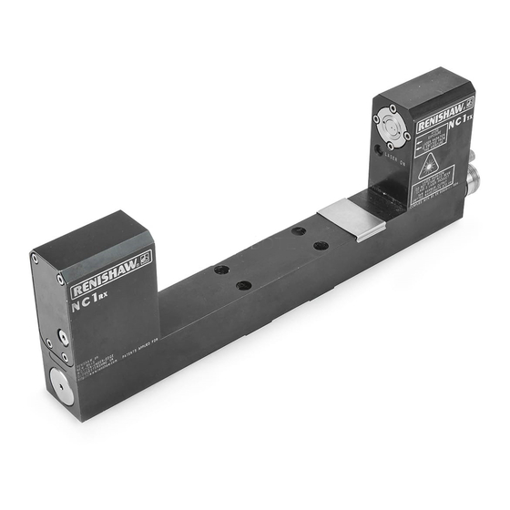
NC1 non-contact
tool setting system
Programming Guide
(Siemens 810D / 840D and FMNC)
Related Manuals for Renishaw NC1
Summary of Contents for Renishaw NC1
-
Page 1
H-2000-6199-02-A R25=y R26=z R11=h R25=y =>?@D NC1 non-contact tool setting system Programming Guide (Siemens 810D / 840D and FMNC) -
Page 2
However, Renishaw makes no warranties with respect to the contents of this document and specifically disclaims any implied warranties. Renishaw reserves the right to make changes to this document and to the product described herein without obligation to notify any person of such changes. -
Page 3
NC1 non-contact tool setting system Programming Guide (Siemens 810D / 840D and FMNC controls) =>?@D www.renishaw.com Renishaw plc New Mills, Wotton-under-Edge, Gloucestershire, GL12 8JR, UK Tel: +44 (0)1453 524524 [07000 RENISHAW] Fax: +44 (0)1453 524901 email: uk@renishaw.com… -
Page 4
Renishaw has no control over the exact program configuration of the controller with which the software is to be used, nor of the… -
Page 5
When using the Beam alignment cycle (subroutine L9860) you will also need to refer to the following Renishaw publication. This contains instructions on how to physically align the beam at the NC1 transmitter unit. NC1 Installation Guide and Parts List… -
Page 6: Table Of Contents
Contents Contents Renishaw NC1 tool setting system …………. 6 Features of the NC1 system software ……….7 Measuring subroutine features ………… 7 Calibration subroutine features ………… 7 Service subroutine features …………8 Software memory requirements …………9 Machine tool controllers supported ………… 9 Tool-offset types supported …………..
-
Page 7: Table Of Contents
Contents Tool radius/diameter setting (subroutine L9862) ……43 Tool length and radius setting (subroutine L9862) ……49 Cutting edge checking (subroutine L9862) ……..55 Broken tool detection – plunge checking (subroutine L9863) ..60 Broken tool detection – radial checking (subroutine L9864) …. 65 Cutter radius and linear profile checking (subroutine L9865) ..
-
Page 8: Renishaw Nc1 Tool Setting System
Renishaw NC1 system Renishaw NC1 tool setting system This guide describes how to use the Renishaw NC1 non-contact tool setting system software. The Renishaw NC1 is a laser-based non-contact tool setting system that provides high-speed/high-precision measurement of cutting tools on a machining centre under normal operating conditions.
-
Page 9: Features Of The Nc1 System Software
Software features Features of the NC1 system software NC1 system software provides the following measuring and calibration features: Measuring subroutine features Four measuring subroutines provide the following features: L9862 – used for measuring the length and diameter of the cutting tool and for cutting edge checking.
-
Page 10: Service Subroutine Features
Software features Service subroutine features The measuring and calibration subroutines are supported by the service subroutines listed below. L9760 – used for the settings data. L9761 – used for startup functions. L9762 – used for the measuring routine. L9763 – used for the G31 routine. L9764 –…
-
Page 11: Software Memory Requirements
You may also remove the following subroutine after you have finished running the Beam alignment cycle: L9860 (laser beam alignment routine) 1.5 Kb (3.8 metres) of memory Machine tool controllers supported NC1 system software is suitable for use on the following machine tool controllers: Siemens 810D Siemens 840D Siemens FMNC…
-
Page 12: Tool-Offset Types Supported
Tool-offset types supported Tool-offset types supported Positive tool-offset applications The NC1 software is ideally suited to setting tools using positive tool- offset values that represent the physical length of the tool. Throughout this programming guide, descriptions refer to positive tool-offset applications.
-
Page 13: Relative To A Master Tool With Zero (0) Tool-Offset Value
Tool-offset types supported RENC[10] = –800.0 Maximum length tool RENC[11]= –950.0 Minimum length tool Relative to a master tool with zero (0) tool- offset value. The master tool-offset register is set to zero (0) and all other tool- offset registers are set as ± values relative to the master tool. Example Home position, to the zero (0) position of the part program = –1000 mm (but this is not important)
-
Page 14: Installing The Software
Installing the software Installing the software Before installing the NC1 software, read the guidelines contained in the Readme file on the software floppy disk. Subroutine parameters The following parameters are used by the NC1 system software: ‘RENT’ global parameters – used for the calibration data and settings data.
-
Page 15: Setting-Data Subroutine L9760
Parameter store for calibration data RENT[24] Position along the beam at which measurements are made. RENT[26] Spindle (length-measuring) axis temperature compensation zero offset. RENT[27] Radial-measuring axis temperature compensation zero offset. Setting-data subroutine L9760 Read the following parameter descriptions then edit subroutine L9760 as described.
-
Page 16
The value is specified when the NC1 system is ordered. Check the status LED sequence on power up (for details, see “NC1 Installation Guide and Parts List ”). RENC[17] Default overtravel distance and radial clearance. Overtravel is the distance through the beam that the tool is permitted to move before a BEAM NOT CUT alarm is initiated. -
Page 17
Setting-data subroutine the beam when moving down the side of the beam. Default: 5 mm (0.197 in) RENC[18] Default measurement resolution (feedrate-per-rev.). Typically 0.001 mm (0.0001 in) feed per revolution. The larger the value, the less accurate measurements will be. Default: 0.002 mm (0.0001 in) RENC[19] Default spindle speed. -
Page 18
Setting-data subroutine If the Z-axis is to be used for radial measurement, select 3. Default: 2 RENC[23] Axis used for length measurement, i.e. the spindle axis. If the X-axis is to be used for length measurement, select 1. If the Y-axis is to be used for length measurement, select 2. -
Page 19
Setting-data subroutine For a description of this feature, see the figure in “Scatter tolerance checking” on page 23. Default: 3 RENC[27] Rapid traverse feedrate. Default: 5000 mm/min RENC[28] Select language. 1 = English, 2 = German, 3 = French, 4 = Italian RENT[5] Number of the digital input for monitoring the probe status signal. -
Page 20
RENC[10]=200.; MAX TOOL LENGTH (8.0 in) RENC[11]=70.; MIN TOOL LENGTH (2.75 in) RENC[12]=80.; MAX CUTTER DIAMETER (3.15 in) RENC[13]=2; TL SET RADIUS MEAS DIR RENC[14]=2; CALIB RADIUS MEAS DIR RENC[15]=.10; NC1-DELAY IN SECS RENC[17]=5.; DEFAULT OVERTRAVEL (0.197 in) RENC[18]=.002; MEASURE RESOLUTION (0.0001 in) -
Page 21: Common Parameters
Setting-data subroutine RENC[19]=3150; DEFAULT RPM RENC[21]=1; BEAM AXIS RENC[22]=2; RADIAL MEASURE AXIS RENC[23]=3; SPINDLE AXIS RENC[24]=.01; SCATTER TOL (0.0004 in) RENC[25]=.025; RUN OUT/CUTTING-EDGE TOL (0.001 in) RENC[26]=1; SAMPLE SCATTER SIZE RENC[27]=5000; RAPID TRAVERSE RENC[28]=1; LANGUAGE 1=GB 2=D 3=FR 4=IT RENT[5]=0;DIGITAL INPUT NO RENT[7]=1;MEASURE INPUT RENT[9]=0;MAGAZINE NUMBER FOR TL MANAGEMENT RENT[28]= ;DISABLE LATCH…
-
Page 22: Customising The Subroutines
In addition to the subroutine customising information described below, further customising and installation information is included in the Readme file supplied with the NC1 software. Editing the measure move subroutine L9762 The back-off move distance can be adjusted for optimisation of the cycles.
-
Page 23: Orientation Of The Nc1 System
Orientation of the NC1 system Orientation of the NC1 system Throughout this guide it has been assumed that the NC1 system is installed with the laser beam parallel to the X-axis. Length measurements are made from the Z-axis and radial measurements are made from the Y-axis.
-
Page 24: Beam-Find And Measuring Moves
Beam-find and measuring moves Beam-find and measuring moves Beam-find moves and measuring moves are all made with the tool moving into the laser beam, as shown in the figure. Measuring moves are made with the tool rotating. Measure Fast Reduced feed feed feed…
-
Page 25: Scatter Tolerance Checking
Scatter tolerance checking Scatter tolerance checking In the following example: The default sample size setting value RENC[26] = 3 is used. The number of retries is automatically set to twice the sample size. In this example, six (6). Sample measurements are taken until either the maximum retries limit is reached, causing an alarm, or a sample of measurements is found to be within limits.
-
Page 26: Beam Alignment (Subroutine L9860)
Setting the measuring point along the beam axis at which the tool is measured. The provisional values are updated later when the calibration cycle is run. Although the Beam alignment subroutine is used mainly during installation of the NC1 system, it can also be used for routine…
-
Page 27
R7=d alignment checking. NOTE: When using the Beam alignment subroutine you will also need to refer to the following Renishaw publication for instructions on how to physically align the beam at the transmitter unit: NC1 Installation Guide and Parts List (Renishaw Part No. -
Page 28
Beam alignment Description Load the calibration tool in the spindle of the machine. Using either the jog or handwheel mode, move the tool to the position that is to be used for tool setting – usually midway along the beam and approximately 10 mm (0.394 in) above the centre of the beam. -
Page 29
Beam alignment Examples R02=1. R07=100. R06=117. R26=15. L9860 R02=1. R07=100. R26=15. L9860 Subroutine inputs The following inputs are used with this subroutine: R02=1. Provisional calibration of the system. Used for checking alignment of the beam and setting the provisional beam positional data (for details, see “Parameter store for calibration data”… -
Page 30
When specifying the value of the R07=d input, take care that it will not allow any part of the tool holder to make contact with the NC1 tool setting system. The projection of the calibration tool should be at least 35 mm (1.38 in) if the default R26=z input is used for the incremental measuring depth. -
Page 31
Beam alignment R18=r r= Diameter of tool This controls the radial clearance move distance. This can be either a positive (+) or negative (–) value. Default value: 30 mm (1.18 in) R26=z z= Incremental measuring depth. This value determines the depth on the calibration tool at which calibration takes place. -
Page 32
Beam alignment RENC[3] Z-axis beam alignment error over the measured span. (This is empty if the Z-axis is the beam axis.) + error If the R02=1 input is used, the following outputs are also set: RENT[20] Provisional Z-axis position of the beam when measured from the positive side of the beam. -
Page 33
Beam alignment Example Beam alignment and setting the provisional beam position %_N_???? ;R02=1 Include approximate set cal. data ;R07=d Axial distance between measures ;R18=r Tool diameter ;R26=z Search distance G0 G53 X302. Y-236. M00 ; Handwheel to position L9800 NOTE: Do not use the R02=1. input if you R02=1.R07=100. -
Page 34: Calibrating The Nc1 (Subroutine L9861)
Calibrating the NC1 Calibrating the NC1 (subroutine L9861) Subroutine L9861 is used for regular calibration of the NC1 system. It should also be used after the laser beam has been aligned with the Beam alignment cycle. The Calibration cycle is used for the following…
-
Page 35
Calibrating the NC1 R06=k R19=s R26=z R26=z R25=y R18=r R17=q Description Load the calibration tool in the spindle of the machine and make the tool number (T) active before running the cycle. The position of the beam in the Z-axis and the centre of the beam in either the X or Y-axis are calibrated while the tool is rotated. -
Page 36
Calibrating the NC1 Format R02=1. R18=r [R03=c R06=k R17=q R19=s R25=y R26=z] L9861 where [ ] denotes optional inputs Example R02=1. R06=100.210 R18=12. R03=4. R17=5. R19=2500. R25=5. R26=5. L9861 Subroutine inputs The following inputs are used with this subroutine: R02=1. -
Page 37
Calibrating the NC1 R18=r r= Reference diameter of the calibration tool. R19=s s= Spindle speed at which calibration takes place. For details, see “Setting-data subroutine L9760” on page Default value: 3150 rev/min R25=y y= Radial step-over for length calibration. The offset across the beam at which measurement takes place. -
Page 38
Calibrating the NC1 RENT[23] X or Y-axis position of the beam, when measured from the negative side of the beam. RENT[24] Position at which the beam is measured. RENT[26] Spindle (length-measuring) axis temperature compensation zero offset. RENT[27] Radial-measuring axis temperature compensation zero offset. -
Page 39
Calibrating the NC1 L9800 R02=1.R06=88.R18=6. L9861 IMPORTANT: If you need to track the axis growth caused by temperature variation during the machining operation, use the R03=c input to store the relevant zero offset registers as reference values. Example: R02=1. R06=88. R18=6. R03=1. -
Page 40: Tool Length Setting (Subroutine L9862)
Tool length setting Tool length setting (subroutine L9862) Subroutine L9862 is used to measure the effective length of a cutting tool. The Tool length measurement cycle is suitable for on-centre setting of tools such as drills and ball-end mills, and for off-centre setting of tools such as face mills and end mills.
-
Page 41
Tool length setting The effective tool length is written to the current tool register and nominated edge number (D). By default, the current tool number and edge will be set. Format [R02=1. R11=h R05=j R13=m R14=t R17=q R19=s R25=y] L9862 where [ ] denotes optional inputs Example R02=1. -
Page 42
Tool length setting the tool length is found to be out of tolerance. Default value: No tolerance check. R13=1. Tool out of tolerance flag. Using this flag prevents a tool OUT OF TOLERANCE alarm from being raised. R14=t t= Tool offset edge to be updated (usually up to nine edges). -
Page 43
Tool length setting Outputs The following outputs are set or updated when this cycle is executed: Set tool length RENC[48] Out of tolerance flag. This is set when the measured tool length is out of tolerance, provided the R11=h input is used. -
Page 44
Tool length setting L9862 A different tool edge offset can be set by using the R14=t input on the call line as follows: Set tool offset edge D2 on centre. R02=1.R14=2.R19=4000. Controlled rev/min. L9862 Tool length setting – off-centre tool Assume the tool is 80mm (3.15in) diameter. -
Page 45: Tool Radius/Diameter Setting (Subroutine L9862)
Tool radius/diameter setting Tool radius/diameter setting (subroutine L9862) Subroutine L9862 is used for measuring the effective radius/diameter of a tool. The Tool radius measure cycle allows the radius/diameter to be measured from the positive side of the beam, from the negative side of the beam, or from both sides of the beam.
-
Page 46
Tool radius/diameter setting made on either one or both sides of the beam (see setting RENC[13] in “Setting-data subroutine L9760” on page 13). The effective radius/diameter is written into the tool offset register. The wear register is zeroed and the radius/diameter value is placed in the geometry register. -
Page 47
Tool radius/diameter setting radius, based on previous experience of how the effective diameter/radius differs from the measured diameter/radius when the tool is under load. Default value: Not used. NOTE: For cutter centre-line programming applications, entering the nominal size as an experience value will result in the error being stored instead of the full radius/diameter of the cutter. -
Page 48
Tool radius/diameter setting R17=q q= Overtravel distance and radial clearance. For details, see “Setting-data subroutine L9760” on page 13. Default value: 5.0 mm (0.197 in) R18=r r= Diameter of tool. This is the nominal diameter of the tool. Default value: Maximum diameter of tool in RENC[12]. -
Page 49
Tool radius/diameter setting Outputs The following outputs are set or updated when this cycle is executed: Set tool radius/diameter RENC[48] Out of tolerance flag. This is set when the measured tool length is out of tolerance, provided the R11=h input is used. -
Page 50
Tool radius/diameter setting R03=2.R14=2. Inputs to set tool radius edge D2. L9862 Tool radius setting 2 Assume the tool is an 80 mm (3.15 in) diameter cutter. %_N_???? L9800 R03=2.R19=800.R18=80. Inputs to set current tool radius edge (default). Controlled rev/min and radial clearance. -
Page 51: Tool Length And Radius Setting (Subroutine L9862)
Tool length and radius setting Tool length and radius setting (subroutine L9862) Subroutine L9862 is used for measuring the effective length and radius/diameter of a tool. The Tool length and radius measure cycle is particularly suitable for tools such as face mills, end mills, slot cutters, disc mill cutters, dovetail cutters and boring tools.
-
Page 52
Tool length and radius setting Description This single cycle combines the Tool length measuring cycle (see “Tool length setting” on page 38) and Tool radius/diameter measuring cycle (see “Tool radius/diameter setting” on page 43). The figure shows the combined cycle moves. Radial measurement (3) can be made on either one or both sides of the beam (see setting RENC[13] in “Setting-data subroutine L9760”… -
Page 53
Tool length and radius setting process. It is used to define the measured diameter/ radius, based on previous experience of how the effective diameter/radius differs from the measured diameter/radius when the tool is under load. Default value: Not used. NOTE: For cutter centre-line programming applications, entering the nominal size as an experience value will result in the error being stored instead of the full radius/diameter of the cutter. -
Page 54
Tool length and radius setting R14=t t= Tool offset edge to be updated (usually up to nine edges). R14=3 Updates the current tool offset, edge D3. If R14 is not input, the current tool offset edge (D) is updated. The current tool is the number of the tool in the spindle. -
Page 55
Tool length and radius setting R25=y y= Radial step-over for length setting. This is the offset across the beam at which length measurement takes place. The value must be less than the radius of the tool. The tool always comes down first on the beam centre-line. -
Page 56
Tool length and radius setting For an explanation of the meaning of alarms, see “Error messages and alarms” on page 85. Examples Tool length/radius setting 1 Assume the tool is a 10 mm (0.394 in) diameter slot drill. %_N_???? L9800 R03=3.R14=2. -
Page 57: Cutting Edge Checking (Subroutine L9862)
Cutting edge checking (subroutine L9862) NOTE: This cycle can be used only if the latch mode feature of the NC1 system is installed and operational. Subroutine L9862 is used for checking the cutting edges of a tool. The diameter Cutting edge check cycle checks for either missing or damaged teeth or for excessive runout of the cutter.
-
Page 58
R06=k input. The spindle speed is calculated from the minimum pulse signal delay RENC[15] of the NC1 system and the number of teeth on the cutting tool. This ensures that when each tooth enters the beam, a permanent beam cut signal is held unless a tooth is either missing or is out of tolerance. -
Page 59
Cutting edge checking R03=c c= The number of teeth on the tool. This automatically selects the cutting edge check. Default value: No default. R06=k k= The tolerance value that defines when the tool cutting edge runout is excessive. Default value: 0.025 mm (0.0098 in) R09=f f= Feedrate-per-rev. -
Page 60
Cutting edge checking signal delay of the control and the number of teeth on the tool. Default value: 3150 rev/min. R24=x x= Cylinder profile checking distance, i.e. the spindle axis movement, while edge checking. The value is incremental from the R26=z input radial measuring position. -
Page 61
Cutting edge checking FORMAT ERROR OUT OF TOLERANCE RPM OUT OF RANGE RUN-OUT/EDGE MISSING For an explanation of the meaning of alarms, see “Error messages and alarms” on page 85. Examples Cutting edge checking Assume a 2-flute slot drill and check for a broken edge 0.5 mm from the end face of the cutter. -
Page 62: Broken Tool Detection – Plunge Checking (Subroutine L9863)
Broken tool detection (plunge check) Broken tool detection – plunge checking (subroutine L9863) Subroutine L9863 is used to check for breakage of cutting tools. The Broken tool cycle uses a plunge check, where the tool is moved into and out of the laser beam in the axis used for length setting. The cycle can also check for a ‘long tool’…
-
Page 63
Broken tool detection (plunge check) Description Detection of a broken tool occurs while the tool is rotated in the beam. Moves into and out of the beam are at the rapid feedrate. The tool first moves over the beam, in the X and Y axes, to the measuring position and then moves, in Z, to the tool checking position. -
Page 64
Broken tool detection (plunge check) R13=1. Tool broken flag. Using this flag prevents a BROKEN TOOL or OUT OF TOLERANCE alarm from being raised. R19=s s= Spindle speed at which checking for a broken tool takes place. For details, see “Setting-data subroutine L9760” on page 13. -
Page 65
Broken tool detection (plunge check) Alarms The following alarms may be generated when this cycle is executed. BROKEN TOOL FORMAT ERROR RPM OUT OF RANGE For an explanation of the meaning of alarms, see “Error messages and alarms” on page 85. Example Broken tool detection –… -
Page 66
Broken tool detection (plunge check) If the broken tool flag method is used, the call cycle is modified as follows: L9800 Make a broken tool check without raising an R26=100.R13=1. alarm. The RENC[48] flag is set. L9863 Go to LN100 IF RENC[48]==1 GOTOF LN100 (continue program) Block LN100 will contain corrective actions. -
Page 67: Broken Tool Detection – Radial Checking (Subroutine L9864)
Broken tool detection (radial check) Broken tool detection – radial checking (subroutine L9864) Subroutine L9864 is used to check for breakage of cutting tools. The Broken tool cycle uses a radial check, where the tool is moved through the laser beam in the direction used for radius/diameter setting.
-
Page 68
At the end of the cycle, the tool moves out of the beam to the safe position in the spindle axis only. CAUTION 1. The latch mode feature of the NC1 system must be installed and operational if the R25=y input is to be used when passing the tool through the beam. -
Page 69
Broken tool detection (radial check) Subroutine inputs The following inputs may be required for this subroutine: R11=h h= Tolerance value that defines when the tool is defined as broken. Default value: 0.5 mm (0.0197 in). R13=1. Tool broken flag. Using this flag prevents a BROKEN TOOL alarm from being raised. -
Page 70
Broken tool detection (radial check) Alarms The following alarm may be generated when this cycle is executed. BROKEN TOOL For an explanation of the meaning of alarms, see “Error messages and alarms” on page 85. Example Broken tool detection – radial check %_N_???? G0Z200. -
Page 71
Broken tool detection (radial check) Select the next tool and continue. (continue machining) If the broken tool flag method is used, the call cycle is modified as shown: L9800 Make a broken tool check R25=50.R26=100.R13=1. without raising an alarm. L9864 The RENC[48] flag is set. -
Page 72: Cutter Radius And Linear Profile Checking (Subroutine L9865)
(subroutine L9865) NOTE: This cycle can be used only if the latch mode feature of the NC1 system is installed and operational. This cycle is used to check the profile of ballnose cutters, cutters with corner radii, and cutters with linear profiles. The profile is checked to find out if it is within a specified form tolerance.
-
Page 73
Cutter radius and linear profile checking With R18=r input –Tol. +Tol. R06=k Checking a profile R18=r with corner radius R24=x R11=h R05=j No R18=r input R17=q –Tol. R25=y +Tol. R17=q R06=k Checking a R24=x linear profile R11=h R25=y Format For radius profile checking R18=r R24=x [R02=b R03=c R09=f R11=h R05=j R06=k R13=m R14=t R17=q R19=s R25=y R26=z] L9865… -
Page 74
Cutter radius and linear profile checking Example R18=10. R24=5. R02=3. R03=4. R09=0.3 R11=1. R05=1. R06=1. R13=1 R14=2. R17=90. R19=4000. R25=5. R26=50. L9865 For linear profile checking R24=x [R02=b R03=c R09=f R11=h R06=k R13=m R14=t R17=q R19=s R25=y R26=z] L9865 where [ ] denotes optional inputs Example R24=5. -
Page 75
Cutter radius and linear profile checking TIP: To prevent retracting at the end of the cycle, use an R26=0 input. R03=c c= When this input is used, enter the number of cutting edges on the tool. The spindle speed is then automatically adjusted to enable errors on each cutting edge to be checked. -
Page 76
Cutter radius and linear profile checking R13=1. Used to prevent an alarm being raised when the profile is out of limits. R14=t t= Tool length offset edge. This is the offset location in which the measured tool length is stored. Default value: Current tool edge. -
Page 77
Cutter radius and linear profile checking R17=q q= Included angle of the cutter radius. Range: 0° 90° ³ £ R18=r r= The cutter radius value. R24=x x= Linear distance moved tangentially past the cutter radius profile (see the figures on page 71). Range: ³… -
Page 78
Cutter radius and linear profile checking Outputs NOTE: When the R02=3. or R02=6. input is used and the tool is found to be out of tolerance during the negative (–) tolerance profile check, the cycle is automatically aborted and does not complete the positive (+) tolerance profile check. -
Page 79
Cutter radius and linear profile checking Examples Profile checking a Ø20 mm (0.787 in) ballnose cutter Check the profile is within ±0.05 mm (0.002 in) The profile checking starts at 1 mm (0.040 in) radial from the cutter centre and then moves around the 90° radius, and then a further 15 mm (0.591 in) up the diameter of the tool %_N_???? L9800… -
Page 80
Cutter radius and linear profile checking Profile checking a Ø20 mm (0.787 in) tapered cutter with 10° side taper Check the profile is within ±0.05 mm (0.002 in). The profile check starts at 1 mm (0.040 in) high and 10.176 mm (0.401 in) radial, and then moves along the taper for 30 mm (1.181 in). -
Page 81: Temperature Compensation Tracking (Subroutine L9861)
Temperature compensation tracking Temperature compensation tracking (subroutine L9861) Subroutine L9861 can be used to calibrate the NC1 system for variations in the spindle axis and/or the radial-measuring axis caused by temperature changes in the machine tool. Run this cycle on a regular basis during machining operations to compensate for growth in the spindle axis and/or radial-measuring axis.
-
Page 82
Refer to the figure showing cycle moves. The subroutine is used as described previously in “Calibrating the NC1 (subroutine L9861)” on page 32, but instead of resetting the calibration data, the beam positions are compared with the original calibration values. The deviation for each axis is then used to adjust the relevant zero offset. -
Page 83
Temperature compensation tracking For spindle axis temperature compensation R02=4. R03=c R06=k [R17=q R19=s R25=y] L9861 where [ ] denotes optional inputs Example R02=4. R03=3. R06=88. R17=5. R19=2500 R25=5. L9861 For radial measuring axis temperature compensation R02=5. R03=c R18=r [R17=q R19=s] L9861 where [ ] denotes optional inputs Example… -
Page 84
This must be the same as that used with the R02 input for calibration Refer to the R03=c input description in “Calibrating the NC1” (page 32) for controller/offset options. R06=k k= Reference length of the calibration tool. R11=h h= Tolerance for the maximum variation of temperature changes. -
Page 85
Temperature compensation tracking Outputs The following outputs are set or updated when this cycle is executed: RENC[12] Temperature compensation error for length measurement. RENC[13] Temperature compensation error for radial measurement. The zero offset axis values are corrected. Alarms The following alarms may be generated when this cycle is executed. ACTIVE BEAM CUT BEAM NOT CUT FORMAT ERROR… -
Page 86
Temperature compensation tracking Example To track the growth in the spindle axis and radial-measuring axis. The external zero offset is used to store the compensations. %_N_???? L9800 R02=6.R03=4.R06=88.R18=6. L9861 Alternatively, if individual axis tracking is required, use either the R02=4. or R02=5. input. -
Page 87: Error Messages And Alarms
Error messages and alarms Error messages and alarms Error messages are displayed by the error subroutine L9769. When an error state is detected, an error message is displayed on the screen of the controller. Error messages, their meaning, and typical actions needed to clear them are described below.
-
Page 88
Error messages and alarms by coolant and swarf on the tool. Also check for mechanical movement of the tool/tip insert or NC1 system. This is a reset condition. Message FALSE TRIGGER Meaning The beam has been cut several times during a measurement move. -
Page 89
Error messages and alarms Message FORMAT ERROR Meaning A subroutine input is either missing or the value entered is incorrect. Action Correct the subroutine input line then run again. This is a reset condition. Message ACTIVE BEAM CUT Meaning The receiver is registering a cut beam signal at the start of a measuring move. -
Page 90
Error messages and alarms Message TOOL OUT OF RANGE Meaning Either the size of the cutting tool exceeds the size that is set in parameters RENC[10] to RENC[12] inclusive, or the tool offset number is wrong. Action Edit the program. Check the cutter size. Message RUN-OUT/EDGE MISSING Meaning… -
Page 91
Renishaw plc, New Mills, Wotton-under-Edge, Gloucestershire GL12 8JR, UK +44 (0)1453 524524 [07000 RENISHAW] +44 (0)1453 524901 Telex 437120 RENMET G email uk@renishaw.com Renishaw Inc, USA Renishaw (Hong Kong) Ltd., Hong Kong, +1 847 286 9953 The People’s Republic of China…
Предложите, как улучшить StudyLib
(Для жалоб на нарушения авторских прав, используйте
другую форму
)
Ваш е-мэйл
Заполните, если хотите получить ответ
Оцените наш проект
1
2
3
4
5
- Manuals
- Brands
- Renishaw Manuals
ManualsLib has more than 491 Renishaw manuals
Accessories
Models
Document Type
A-1332-0002
User Manual
A-1332-0003
User Manual
A-1332-0004
User Manual
A-1332-0005
User Manual
A-1332-0006
User Manual
A-1332-0007
User Manual
A-1332-0008
User Manual
A-1332-0009
User Manual
A-1332-0010
User Manual
A-1332-0011
User Manual
Show all Renishaw Accessories manuals
Amplifier
Models
Document Type
A-5518-0025
Installation Manual
A-5518-2500
Installation Manual
A-5518-2550
Installation Manual
A-5629-0100
Installation Manual
A-5629-0200
Installation Manual
A-5629-0300
Installation Manual
apply innovation SPA2
Installation Manual
H-1000-5068-02-A SPA1 s
Installation Manual
SPA1
Installation Manual
• Installation Manual
• Installation Manual
Show all Renishaw Amplifier manuals
Analytical Instruments
Models
Document Type
OLP40
Installation Manual
• Quick Start Manual
• Quick Start Manual
• Installation Manual
OMP40-2
Quick Start Manual
• Quick Start Manual
• Installation Manual
• Installation Manual
• Quick Start Manual
• Manual
PH20
Installation And User Manual
• User Manual
• Operation And Maintenance
Control Unit
Models
Document Type
A-2028-7574
Installation Manual
HSI
Quick Start Manual
• Installation Manual
IMP
Manual
MCR20
User Instruction
OMM
Repair Instructions
• Manual
SLM 250
Installation And Operation Manual
Controller
Models
Document Type
MCU1
User Manual
MCU5
User Manual
MCUlite-2
User Manual
PHC10-3 PLUS
Installation And User Manual
• Installation Manual
• Installation And User Manual
• Installation Manual
UCC dynamic mapping tool
User Manual
UCC MMI
Installation Manual
UCC MMI-2
Installation Manual
UCC PI 80
Installation Manual
UCC S3
Installation Manual
Show all Renishaw Controller manuals
DC Drives
Models
Document Type
Equator 500
Installation Manual
• Installation Manual
Diagnostic Equipment
Models
Document Type
A-5504-0040
Installation Manual
A-5504-0050
Installation Manual
A-6078-0070
Installation Manual
A-6078-0085
Installation Manual
ADTa-100
User Manual
ADTi-100
User Manual
• User Manual
Equator
Installation Manual
Equator 300
Product Information
• Installation Manual
Equator 300 Extended Height
Installation Manual
Equator 500
Installation Manual
• Installation Manual
Show all Renishaw Diagnostic Equipment manuals
Industrial Electrical
Models
Document Type
OMI-2
Installation Manuals
• User Manual
• Installation And User Manual
• Quick Start Manual
RGA22
User Manual
Industrial Equipment
Models
Document Type
Equator A-5924-0350
Assembly Instructions Manual
Equator ATS 40-800
Installation And User Manual
Equator EQ-ATS
Installation Manual
HPGA
Installation And User Manual
HSI-C
Installation Manual
• Quick Start Manual
InfiniAM Spectral
User Manual
Kiosk workstation
User Manual
LP2
Installation And User Manual
• Installation And User Manual
• Installation Manual
LP2DD
Installation And User Manual
• Installation Manual
LP2H
Installation And User Manual
• Installation Manual
Show all Renishaw Industrial Equipment manuals
Laboratory Equipment
Models
Document Type
H-1000-5071-09-A
Installation Manual
PH10
Installation Manual
PH10M
Installation Manual
PH10MQ
Installation Manual
PH10T
Installation Manual
PHC10-2
Installation Manual
Laser Shaft Alignment Tools
Models
Document Type
XK10
User Manual
• Manual
Measuring Instruments
Models
Document Type
A-1073-0121
User Manual
A-1073-0261
User Manual
A-2085-0068
Installation Manual
A-4071-0060
Installation Manual
A-5000-3709
Installation Manual
A-5471-2011
Installation Manual
A-5472-0060
Installation Manual
A-5472-2001
Installation Manual
A-5472-3000
Installation Manual
A-5472-3003
Installation Manual
Show all Renishaw Measuring Instruments manuals
Media Converter
Models
Document Type
ATOM
Installation Manual
• Installation Manual
• Installation Manual
• Installation Manual
ATOM DX
Installation Manual
• Installation Manual
ATOM DX Series
Installation Manual
ATOM Series
Installation Manual
EVOLUT RTLA50
Installation Manual
EVOLUTE FASTRACK
Installation Manual
Show all Renishaw Media Converter manuals
Microphone system
Models
Document Type
MP18
Installation And User Manual
Other
Models
Document Type
ADTi-100
User Manual
• User Manual
Power Supply
Models
Document Type
PSU3
Installation And User Manual
RCU10
Installation And User Manual
Power Tool
Models
Document Type
Primo LTS
User Manual
Power Tool Accessories
Models
Document Type
APCA-45
Installation And User Manual
MP11
Installation Manual
RTS
Quick Start Manual
• Quick Start Manual
• Installation Manual
TS27R
Installation And User Manual
• Installation Manual
Racks & Stands
Models
Document Type
ACR3
Installation And User Manual
MRS2
Installation Manual
Receiver
Models
Document Type
OMI-2T
Quick Start Manual
OMM
Repair Instructions
• Manual
OMM-S SPRINT
Installation Manual
• Quick Start Manual
OMME
Repair Instructions
OSI-S SPRINT
Installation Manual
• Quick Start Manual
Recording Equipment
Models
Document Type
A-5923-0050
User Manual
A-5923-0259
User Manual
A-9926-0700
User Manual
EQUATOR EQ-IQ
User Manual
H-2000-5015-05-N
Installation And User Manual
HSI
Quick Start Manual
• Installation Manual
HSI-C
Installation Manual
• Quick Start Manual
MI 12
Installation And User Manual
MI5
Installation And User Manual
NCi-6
Installation And User Manual
• Installation Manual
Show all Renishaw Recording Equipment manuals
Sander
Models
Document Type
LTO2
Installation And User Manual
Scanner
Models
Document Type
Quarryman Pro
Hardware Manual
RETROSCAN
Installation Manual
Security Sensors
Models
Document Type
TRS1
Programming Manual
• Installation And User Manual
TRS2
Installation Manual
Test Equipment
Models
Document Type
A-5003-2280
User Instructions
MIP
User Manual
Show all Renishaw Test Equipment manuals
Tools
Models
Document Type
A-5514-8500
Quick Start Manual
NC4
Cleaning Instructions Manual
• Manual
• Installation Manual
• Installation And Maintenance Manual
NC4+ Blue
Installation Manual
• Quick Start Manual
NC4+ Blue F115C
Manual
NC4+ Blue F115C-R
Manual
NC4+ Blue F145C
Manual
NC4+ Blue F145C-R
Manual
NC4+ Blue F230C
Manual
NC4+ Blue F230C-R
Manual
Show all Renishaw Tools manuals
Ultrasonic Jewelry Cleaner
Models
Document Type
Equator cleaning kit
User Manual
Valve Positioners
Models
Document Type
ACR2
Installation Manual
гарантируете, что во время обучения не произойдёт поломки датчика, а в случае поломки берёте на себя покупку нового? Сколько времени займёт обучение? после обучения дадите какой-либо сертификат, подтверждающий, что обучаемый освоил программу и выполнит контрольные задания (или обучение происходит в частном порядке за определённую сумму денег вруки)? стоимость?
Датчик MP700 (3-х мерный с ИК связью с приёмником), ЧПУ Sinumerik 840D.
гарантируете, что во время обучения не произойдёт поломки датчика, а в случае поломки берёте на себя покупку нового Могу, но это отразаится на стоимости обучения.
после обучения дадите какой-либо сертификат, подтверждающий, что обучаемый освоил программу и выполнит контрольные задания. К сожалению, такого сертификата и сам не имею. Можем совместно составить задание, дать его обучаемому и посмотреть, как он его выполнит.
или обучение происходит в частном порядке за определённую сумму денег вруки да в частном, можно по договору, деньги можно в руки, можно на расчетный счет.
Сумма зависит, от того, что Вы хотите получить в результате, насколько подготовлен обучаемый. Если интересует более конкретно давайте связываться через ICQ, email (см мой профиль)