
-
Contents
-
Table of Contents
-
Bookmarks
Quick Links
REOVIB
Control Equipment for the Vibratory Feeder Industry
MFS 268
Frequency Converter for Vibratory Feeders
UL / CSA — Version
268_UL-CSA_ANL_EN_47-13.DOC
21.11.2013
Related Manuals for Reo Elektronik REOVIB MFS 268
Summary of Contents for Reo Elektronik REOVIB MFS 268
-
Page 1
REOVIB Control Equipment for the Vibratory Feeder Industry MFS 268 Frequency Converter for Vibratory Feeders UL / CSA — Version 268_UL-CSA_ANL_EN_47-13.DOC 21.11.2013… -
Page 2: Technical Safety Instructions For The User
The units described herein are electrical controllers for installation in industrial plant. They are designed for controlling vibratory feeders. For use in NFPA 79 Applications only Adapters providing field wiring means are available from REO ELEKTRONIK AG. Refer to REO ELEKTRONIK AG.
-
Page 3: Table Of Contents
REOVIB MFS 268 UL/CSA Operating Instructions ELEKTRONIK Contents Technical safety instructions for the user ………………… 1 1.0 General …………………………3 2.0 Function …………………………3 2.1 Track control ……………………….4 2.2 Operating with two speeds (2 set points for coarse/fine switching) ………… 4 2.3 Control inputs and output ……………………
-
Page 4: General
ELEKTRONIK 1.0 General The REOVIB MFS 268 range comprises special, adaptable controllers for use with vibratory feeders. The units generate an output frequency, to drive feeders, that is independent of mains frequency and so exact tuning with springs is not necessary. The feeders also run quieter because of the sinusoidal output signal.
-
Page 5: Track Control
REOVIB MFS 268 UL/CSA Operating Instructions ELEKTRONIK 2.1 Track control output switched ON and OFF Sensor from a track component sensor, using internal, adjustable time delays (ton Feeder and toff). The queue of components rises above and drops below the track sensor…
-
Page 6: Output Status Relay
REOVIB MFS 268 UL/CSA Operating Instructions ELEKTRONIK 2.3.4 Output status relay Status-Relay contact 250 V/1 A (changeover). Relay closes when the feeder is running – the relay opens when there is no enable signal or a fault displayed. 2.3.5 Time-Out output 24 VDC «time Out»…
-
Page 7: Technical Data
For use in NFPA 79 Applications only E217179 Adapters providing field wiring means are available from REO ELEKTRONIK AG. Refer to REO ELEKTRONIK AG. 6.0 Declaration of Conformity We declare that these products conform with the following standards: EN 61000-6-4 and EN 61000-6-2 in accordance with the regulations of guidelines 2004/108/EC.
-
Page 8: Settings
REOVIB MFS 268 UL/CSA Operating Instructions ELEKTRONIK 7.0 Settings After checking the correct operation of the controller in conjunction with the vibratory feed system it is advisable to restrict the user to feeder throughput settings only. Setting the feeder throughput: Press the P key twice and adjust the throughput with the cursor keys (Code C.
-
Page 9: Control Elements
REOVIB MFS 268 UL/CSA Operating Instructions ELEKTRONIK 8.0 Control elements 8.1 Settings The six buttons and a LED display found in the front panel, are used for operating and setting up the unit. All operating methods and adjustable Display parameters can be set up through this panel.
-
Page 10: Commissioning
REOVIB MFS 268 UL/CSA Operating Instructions ELEKTRONIK 9.0 Commissioning 9.1 Assembling position Please fasten the devices on a vibration-free underground and take care for sufficient air circulation. 9.2 Preliminary steps • Check that the unit is correct for the local mains supply (rating plate information) and that it is correct- ly rated for the feed system.
-
Page 11: Putting The Equipment Into Operation
REOVIB MFS 268 UL/CSA Operating Instructions ELEKTRONIK 9.3 Putting the equipment into operation 1. Establish the vibrating frequency. 2. Establish the power of the feed system (maximum permissible current draw). For a new feeder where settings are unknown: (see also comments below) Without connecting the feeder, select parameter FAC in menu C210 (reset factory settings), press the cursor key to reset (SAFE) and press the P key to leave the menu.
-
Page 12: Setting Instructions
REOVIB MFS 268 UL/CSA Operating Instructions ELEKTRONIK 10.0 Setting Instructions 10.1 User adjustment of throughput Code C. 000 Feeder amplitude set point 0…100 % Running mode A further set point code can be found under C002 (for use in coarse/fine operation) Feeder amplitude set point 0…100 %…
-
Page 13: Track Control
REOVIB MFS 268 UL/CSA Operating Instructions ELEKTRONIK 10.2.2 Track control Code C. 167, 007 On time delay 0…60 sec. Off time delay 0…60 sec. 0 = No sensor inverting I = Sensor inverting 0 = Sensor time out not active I = Sensor time out active E.
-
Page 14: Pulse Feed
REOVIB MFS 268 UL/CSA Operating Instructions ELEKTRONIK 10.2.5 Pulse feed Code C. 004, 064 HOP. = 0 = continuous duty HOP. = I = pulse feed On time delay [sec.] Off time delay [sec.] Invert hopper sensor (not active) Running mode 10.2.6 Regulation mode…
-
Page 15: Instructions For Using Regulation Mode
REOVIB MFS 268 UL/CSA Operating Instructions ELEKTRONIK 10.2.6.1 Instructions for using regulation mode • An accelerometer e.g. SW 70 must be fitted to the vibratory feeder in order to run in regulation mode. The accelerometer should have a frequency range corresponding to that of the feeder.
-
Page 16
REOVIB MFS 268 UL/CSA Operating Instructions ELEKTRONIK In regulation mode the magnitude of the output signal has a direct affect on the maximum ampli- tude of the feeder. On bowl feeders it is advisable to fit the sensor as near as possible to the outside diameter and in this… -
Page 17: Relationship Between Acceleration And Amplitude
REOVIB MFS 268 UL/CSA Operating Instructions ELEKTRONIK 10.2.6.3 Relationship between acceleration and amplitude The sensor measures the momentary acceleration of the feeder. It generates a sinusoidal output voltage signal. The acceleration gets higher as the frequency increases. The sensor signal is greater for a higher frequency and lower amplitude than for a low frequency with a higher amplitude.
-
Page 18: Optimisating Controller In Regulation Mode
REOVIB MFS 268 UL/CSA Operating Instructions ELEKTRONIK 10.2.6.6 Optimisating controller in regulation mode Setting the control range 1. In Menu C. 096 set parameter P (Max Limit) to 50 % 2. Set A (Feeder throughput) to 100% 3. Increase limit P from 50% until the required maximum feeder throughput is achieved The full set point adjustment range of 0…100% can now be used…
-
Page 19: Display Actual Current And Frequency
REOVIB MFS 268 UL/CSA Operating Instructions ELEKTRONIK 10.2.7 Display actual current and frequency Code C. 040 Actual current (display only) Actual frequency (display only) Running mode 10.2.8 Save selected parameters Code C. 143 Choose user parameter set Save new parameters Running mode 10.2.9 Recall user or factory settings…
-
Page 20: Error Messages / Error Reset
REOVIB MFS 268 UL/CSA Operating Instructions ELEKTRONIK 11.0 Error messages / ERROR reset Errors are indicated by an alternating code and ERROR display Overload limit Output level exceeded e.g. incorrect frequency setting, coil air- gap to wide. Short circuit trip Faulty coil, short circuit or defective cable..
-
Page 21: Connections For Enclosed Construction (Ip 54): 6-8 A Units
REOVIB MFS 268 UL/CSA Operating Instructions ELEKTRONIK 12.0 Connections for enclosed construction (IP 54): 6-8 A Units Internal connections When a potentiometer is connected parameter POT must be set to I in Menu C003. Status- relay 1 2 3 4…
-
Page 22: Connections For Enclosed Construction (Ip 54): 12 A Units
REOVIB MFS 268 UL/CSA Operating Instructions ELEKTRONIK 12.1 Connections for enclosed construction (IP 54): 12 A Units Internal connections Status relay Time out +24 V Air valve +24 V +24 V Accelerometer SW… INPUT Set point (external) +10V 0(4)…20mA 0…10V…
-
Page 23: Connections For Enclosed Construction (Ip 54): 16 A Units
REOVIB MFS 268 UL/CSA Operating Instructions ELEKTRONIK 12.2 Connections for enclosed construction (IP 54): 16 A Units Internal connections Status relay Time out +24 V Air valve +24 V +24 V Accelerometer SW… INPUT Set point (external) +10V 0(4)…20mA 0…10V…
-
Page 24: Connections For Panel Mounting Construction (Ip 20): 3 A, 6 A, 8 A
REOVIB MFS 268 UL/CSA Operating Instructions ELEKTRONIK 13.0 Connections for panel mounting construction (IP 20): 3 A, 6 A, 8 A REOVIB MFS268 Material-Sensor +24V Enable 12…24V, DC Set point 0…10V 0(4)…20mA R=500 OHM black External INPUT orange SW… + 24V…
-
Page 25: Connections For Panel Mounting Construction (Ip 20): 16A
REOVIB MFS 268 UL/CSA Operating Instructions ELEKTRONIK 13.1 Connections for panel mounting construction (IP 20): 16A line choke Mains L, N, PE / 115V/230V, 50/60HZ Material sensor +24V Enable 12…24V, DC Set point 0(4)…20mA 0…10V SPEED +10V black orange INPUT Accelerometer SW…
-
Page 26: Dimensions For 3 A, 6 A, 8 A Units
REOVIB MFS 268 UL/CSA Operating Instructions ELEKTRONIK 14.0 Dimensions for 3 A, 6 A, 8 A Units Enclosed construction, (IP 54) Ø5,0 REOVIB MFS 268 SPEED www.reo.de Ø5,0 Panel mounting construction, (IP 20) Ø 5,0 Ø 5,0 REOVIB MFS268 REOVIB MFS268 Ø…
-
Page 27: Dimensions Of Enclosed Construction (Ip 54) 12 A
REOVIB MFS 268 UL/CSA Operating Instructions ELEKTRONIK 14.1 Dimensions of enclosed construction (IP 54) 12 A Ø5,0 REOVIB MFS 268 SPEED www.reo.de Ø5,0 14.2 Dimensions of enclosed construction (IP 54) 16 A Ø5,0 REOVIB MFS 268 SPEED www.reo.de Ø5,0…
-
Page 28: Dimensions Of Panel Mounting Construction (Ip 20) 16 A
REOVIB MFS 268 UL/CSA Operating Instructions ELEKTRONIK 14.3 Dimensions of Panel mounting construction (IP 20) 16 A Ø5,0 SPEED +10V Ø5,0…
-
Page 29: A 1.0 Service Appendix
REOVIB MFS 268 UL/CSA Operating Instructions ELEKTRONIK A 1.0 Service appendix ATTENTION ! The settings described in this section relating to the service menu are intended for use by skilled persons because the functions and limits of the feed system can be greatly influenced by their…
-
Page 30
REOVIB MFS 268 UL/CSA Operating Instructions ELEKTRONIK Frequency adjustment range The control unit is supplied with a maximum frequency range of 5…150Hz. Using an adjustable under and over frequency limits, the user range (parameter F) can be restricted to a maximum ratio of 1:4. -
Page 31
REOVIB MFS 268 UL/CSA Operating Instructions ELEKTRONIK Enable Service Mode The actual service menu is accessed by opening the service mode. 0 = Service mode off I = Service mode on Running mode The normal service menu, containing the output current and frequency limit settings, is accessed by opening the service mode. -
Page 32: A 2.0 Accessories / Spare Parts
REOVIB MFS 268 UL/CSA Operating Instructions ELEKTRONIK A 2.0 Accessories / Spare Parts Reo Order Type: Accessories / Spare Parts: Number: Manufacturer Order Number: Harting: 09 20 003 2711 + 19 20 003 1440 + mains input coupling 19 00 000 5082 + 09 20 000 9918…
-
Page 33
REOVIB MFS 268 UL/CSA Operating Instructions ELEKTRONIK… -
Page 34
Headquarters — Germany REO ELEKTRONIK AG Brühler Straße 100 · D-42657 Solingen Tel.: +49 (0)212 8804 0 · Fax: +49 (0)212 8804 188 REO INDUCTIVE COMPONENTS AG Brühler Straße 100 · D-42657 Solingen Tel.: +49 (0)212 8804 0 · Fax: +49 (0)212 8804 188 E-Mail: info@reo.de…
REOVIB MFS 268 UL/CSA
Operating Instructions
This description contains the necessary information for the correct application of the product described
below. It is intended for use by technically qualified personal.
Qualified personnel are persons who, because of their training, experience and position as well as their
knowledge of appropriate standards, regulations, health and safety requirements and working conditions,
are authorised to be responsible for the safety of the equipment, at all times, whilst carrying out their nor-
mal duties and are therefore aware of, and can report, possible hazards (Definition of qualified employees
according to IEC 364)
Safety Instructions
The following instructions are provided for the personal safety of operators and also for the protection of
the described product and connected equipment.
Warning!
Hazardous Voltage
!
Failure to observe can kill, cause serious injury or damage
•
Isolate from mains before installation or dismantling work, as well as for fuse changes or post installa-
tion modifications.
•
Observe the prescribed accident prevention and safety rules for the specific application.
•
Before putting into operation check if the rated voltage for the unit conforms with the local supply
voltage.
•
Emergency stop devices must be provided for all applications. Operation of the emergency stop must
inhibit any further uncontrolled operation.
•
The electrical connecting terminals must be covered!
•
Earth bonding must be tested for integrity after installation.
Specified Use
The units described herein are electrical controllers for installation in industrial plant.
They are designed for controlling vibratory feeders.
For use in NFPA 79 Applications only
Adapters providing field wiring means are available from REO ELEKTRONIK AG.
Refer to REO ELEKTRONIK AG.
ELEKTRONIK
1
REO REOVIB MFS 268: List of Available Documents
Note for Owners:
Guidesimo.com webproject is not a service center of REO trademark and does not carries out works for diagnosis and repair of faulty REO REOVIB MFS 268 equipment. For quality services, please contact an official service center of REO company. On our website you can read and download documentation for your REO REOVIB MFS 268 device for free and familiarize yourself with the technical specifications of device.
More Controller Devices:
-
Carel FSC Series
Thank you for your choice. We trust you will be satisfied with your purchase.General characteristicsThe FCS series equipment are three-phase electronic voltage controllers that use the phase-cutting principle in order to regulate the output voltage supplied on the load, as a function of the driving signal being applied to the input. They can drive asynchronous electric motors connected for example …
FSC Series Controller, 2
-
RNA ESK 2002
Rhein-Nadel Automation GmbH 1 14.04.2014 VT-BA ESK2002-GB Operating Instructions for the Control Units of Vibratory Drives ESK 2002 BA Rhein-Nadel Automation GmbH …
ESK 2002 Control Unit, 17
-
Eaton ELC Series
ELC/ELC2 Series Programmable Logic Controllers INSTRUCTION SHEET [Applicable Controllers] ELC-PV28NNDR ELC-PV28NNDT ELC2-PV28NNDR ELC2-PV28NNDT ELC2-PV28NNDP 5011670405-PVT52014-10-30 IL050006EN …
ELC Series Controller, 12
-
Comunello Automation SALIENT
SALIENT / SALIENT SLOWINSTALLATION AND USER’S MANUALElectromechanical actuatorsfor projecting up and over and sectional spring-loadedcomunello.comISTRUZIONI D’USO E DI INSTALLAZIONEINSTALLATIONS-UND GEBRAUCHSANLEITUNG INSTRUCIONS D’UTILISATION ET D’INSTALLATIONINSTRUCCIONES DE USO Y DE INSTALACIONИНСТРУКЦИЯ ПО МОНТАЖУ91300127 — Rev. 01 — 30.12.14 …
SALIENT Controller, 32
Recommended Documentation:
Complete catalog
Download our extensive catalog and discover many other REO products.

Data sheet
All data and configurations can be found in our product data sheet.
Certifications
Optional UL-certified
Interfaces
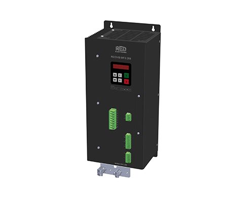
FREQUENCY CONVERTER REOVIB MFS 268 HP-HC2
IP 20, High-power version
Description
High-power version of the REOVIB MFS 268 frequency-control device, can be used for mains voltages of 400 V with max. 8 or 16 A output current and for mains voltages of 230 V with max. 12, 16, 32 A output current. Available as IP20 versions for installation in control cabinets and also as IP54 standalone units for 230 V and 12/16 A. We are also delighted to offer you a suitable control cabinet system with client specific requirements. Special designs of the REOVIB MFS 268 HP can also be implemented if required.
Advantages
- Independant of the mains input frequency
- Able to automatically determine the resonant frequency of the vibratory conveyor system (with additional vibration amplitude sensor) and regulate the vibration amplitude and maintain a constant feedrate irrespective of load or changes in the mechanical system
- Field bus interfaces: ProfiNet, EtherNet/IP, EtherCAT, CAN-Bus, ProfiBus, DeviceNet
- Available with UL/CSA approval depending on the type (Optional)
- Conveyor frequencies adjustable between 5…300 Hz
- Mains voltage compensation with constant vibration amplitude
- All settings can be made using the integrated display
- Sinusoidal output current
- Can be used on 230 V or 400 V mains input
- User settings can be stored
- Fill level/overflow control
- Versions available in various protection classes and connector options
- MFS 269 HP is availble with AC output signal for use with permanent-magnet armature.
Technical data

Suitable for this product

AC Magnets

Accelerometers
Contact
Contact and product inquiry
We are there for you
Do you have questions, requests or suggestions?
Please don’t hesitate to contact us:
REO AG
Brühler Strasse 100
D-42657 Solingen
Tel.: 0049-(0)2 12-88 04-0
Fax: 0049-(0)2 12-88 04-188
E-Mail: info@reo.de
USt-ID-Nr.: DE 182 486 130
St.-Nr.: 128/5819/5634
Table of Contents for REO REOVIB MFS 268:
-
Operating Instructions Interface Programming REOVIB MFS 268 — RS 232 9 ELEKTRONIK 3.2.7 Bit Configured Parameter Bit information. Change individual Bits in a control word. Each bit sets a switch which enables or inhibits a function. In the user program this bit “manipulation“ must be isolated in a table. If required more than one bit may be altered simultaneously. Parameter address 1800 H-Byte L-Byt
-
Operating Instructions Interface Programming REOVIB MFS 268 — RS 232 15 ELEKTRONIK 6 Dimension 6.1 Dimension 6 A unit 35 70 17412 6,5 175 205 21 22 23 24 25 26 27 28 291 2 3 4 5 6 7 8 9 31 32 33 34 MFS 1 6 2 7 3 8 4 9 5 21 22 23 24 25 26 27 28 29 31 32 33 34 1 2 3 4 5 6 7 8 9 Ø5,0 Ø5,0 F I 0P P P P
-
Operating Instructions Interface Programming REOVIB MFS 268 — RS 232 8 ELEKTRONIK Receive Confirmation H-Byte L-Byte Word 1 Confirmation of the sent address + R / W — Bit 15 14 13 12 11 10 9 8 7 6 5 4 3 2 1 0 R / W Parameter address H-Byte L-Byte Word 2 Confirmation parameter value XX XX H-Byte L-Byte Word 3 Confirmation parameter mode (always “C0DE“ H) C0 DE
-
Operating Instructions Interface Programming REOVIB MFS 268 — RS 232 11 ELEKTRONIK 5.0 Example of serial interface communication with frequency controller REOVIB MFS 268 Variable values are written in italics. 5.1 Normal Operation (set point set at 70 %) Send set point Word Contents Send Contents Receive 1 B332 H Set point = 70 % — — 2 3 0004 H Enable ON A5xx H Ready RS 232 Character string «B33200000004″+CR RS 232 Character string «00000000A5xx»+CR (Control STOP) Send Se
-
Operating Instructions Interface Programming REOVIB MFS 268 — RS 232 5 ELEKTRONIK 3.1 Normal operation In normal operation the serial interface is used to adjust the set point for the feeder throughput and the digital control signals e.g. the enable. The unit status (ready or fault) is reported. All data words are in the range 0000..FFFF H. The communications words are shown in bit form as follows.
-
Operating Instructions Interface Programming REOVIB MFS 268 — RS 232 4 ELEKTRONIK The serial interface information is sent as a character string that is closed with a RETURN (CR) for synchronization. Within the string there are three used data words each having four characters (Bytes). The complete data string therefore comprises 3 x 4 + 1 characters. Each part character string of the data word is the hexadecimal code equivalent of the 16 bit integer expression of the used data. Only upper case characters «0» to &quo
-
Operating Instructions Interface Programming REOVIB MFS 268 — RS 232 6 ELEKTRONIK 3.2 Parameter operation The unit specific parameters can be read and changed in Parameter Operation. Before writing parameters a write enable must be sent. Then it is possible to change a single or several parameters. On closing the write enable must be removed. A read request only is required for reading The response value of Word 3 is alwa
-
Operating Instructions Interface Programming REOVIB MFS 268 — RS 232 10 ELEKTRONIK 4.0 Parameter Table Non listed addresses should not be changed. Settings Setting range Display- Code Factory settings Entry code Parameter address HEX (.bit) Value range HEX Förderer • Ampltude (throughput) 0..100 % A. 0 % 000, 002, 008, 096 100C 0…FFFF H • Maximum control range (U max
-
Operating Instructions Interface Programming REOVIB MFS 268 — RS 232 3 ELEKTRONIK 1.0 General The REOVIB MFS 268 range of controllers for vibratory feeders can be operated from an RS 232 interface. To do this the frequency controller must be set up to receive serial data, using Menu “C 017” (S.I.F. = I ). The set point for feeder throughput is adjusted in “Running Mode“ and the controller status (ready/fault) is transmitted back. The controller can be co
-
Operating Instructions Interface Programming REOVIB MFS 268 — RS 232 7 ELEKTRONIK 3.2.2 Send Write enable H-Byte L-Byte Wort Address Write Key =C0DE H C0 DE H-Byte L-Byte Word 2 Write Key =B5E7 H B5 E7 H-Byte L-Byte Word 3 Control Word + 8000 H Mode bit must be set to 1 !! All bits not used must be “0”. Bit = “1“ = Function ON 15 14 13 12 11 10 9 8 7 6 5 4 3 2 1 0 1 Mode bit 0 0 0 0 0 0 0 0 0 0 0 0 0 0 Control Information (unit specific) 3.2.3 Receive
-
Operating Instructions Interface Programming REOVIB MFS 268 — RS 232 14 ELEKTRONIK 5.3 RESET of Controller Write enable Word Contents Send Contents Receive 1 C0DE H Adress write key C0DE H Confirmation 2 B5C9 H Value write key B5C9 H Confirmation 3 8000 H + Control bits Set Mode bit = 1 C0DE H Confirmation RS 232 Character string «CODEB5C98000″+CR RS 232 Character string «CODEB5C9CODE»+CR Write parameter 1 9400 H Pa
Questions, Opinions and Exploitation Impressions:
You can ask a question, express your opinion or share our experience of REO REOVIB MFS 268 device using right now.