Регулятор Reval 182 применяется на узлах редуцирования и стабилизации выходного давления газа в сетях газораспределения и газопотребления, а так же в котельных.
Основные преимущества:
- высокая точность регулирования давления;
- компактность;
- очень низкий рабочий перепад давления;
- большой рабочий диапазон;
- модульная конструкция;
- возможно установить дополнительное шумоглушение;
- возможность установки отсекающего клапана;
- возможность установки дополнительного регулятора-монитора в тот же корпус.
Этот дополнительный аварийный регулятор (монитор) непосредственно встроен в корпус основного регулятора. Оба регулятора давления хотя и используют один и тот же корпус клапана, имеют независимые приводы, пилоты и седла клапана.
Рабочие характеристики монитора PM/182 такие же, как и для регулятора Reval 182. Коэффициенты Cg и KG регулятора со встроенным монитором на 8% ниже, нежели коэффициенты для стандартной версии. Еще одно большое преимущество, предлагаемое встроенным регулятором-монитором, заключается в возможности его установки в любое время, даже на уже существующий регулятор, без внесения изменений в трубопровод. Это решение позволяет производить линии редуцирования более компактных размеров.
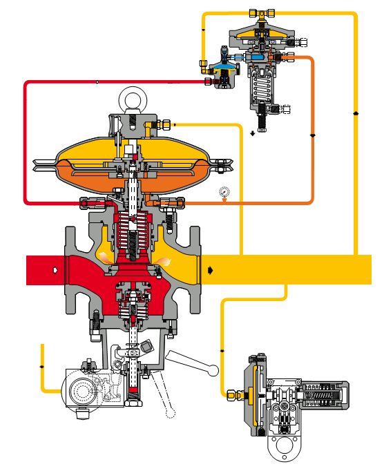
Регулятор со встроенным отсекающим клапаном
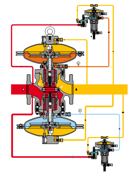
Регулятор со встроенным регулятором-монитором
Регулятор Reval 182 работает по принципу «в случае аварии регулятор закрыт». И при возникновении неисправностей должен закрываться, в частности, при следующих условиях:
- основная диафрагма повреждена;
- диафрагма пилота повреждена;
- отсутствует питание в контуре пилота.
Технические характеристики:
- проектное давление: до 25 бар;
- температура окружающей среды: -30 °C ÷ +60 °C;
- диапазон входного давления bpe: 0,15 до 25 бар ;
- диапазон выходного давления Wh: 7 мбар до 12 бар в зависимости от установленного пилота;
- минимальный рабочий перепад давлений: 0,1 бар;
- класс точности AC: до 2,5;
- класс давления закрытия SG: от 10 до 5 в зависимости от выходного давления;
- имеющийся размер DN 25-50-65-80-100-150-200-250
- фланцевые соединения: класс 150 RF /RTJ или РN 15/25/40 согласно ISO 7005
*Более подробную информацию можно посмотреть в техническом описании прибора.

-
Contents
-
Table of Contents
-
Bookmarks
Quick Links
E
PRESSURE REGULATOR
REVAL 182
TECHNICAL MANUAL MT043
INSTALLATION, COMMISSIONING AND MAINTENANCE INSTRUCTIONS
| sales@mvandc.com | Phone: 877.566.3837 | Fax: 925.407.2903
www.mvandc.com
Related Manuals for PIETRO FIORENTINI REVAL 182
Summary of Contents for PIETRO FIORENTINI REVAL 182
-
Page 1
PRESSURE REGULATOR REVAL 182 TECHNICAL MANUAL MT043 INSTALLATION, COMMISSIONING AND MAINTENANCE INSTRUCTIONS | sales@mvandc.com | Phone: 877.566.3837 | Fax: 925.407.2903 www.mvandc.com… -
Page 2
TECHNICAL MANUAL MT043 REVAL 182 RR 40 R14/A 204/A MOTORIZATION INLET PRESSURE OUTLET PRESSURE PILOT FEED Issue November 2002 | sales@mvandc.com | Phone: 877.566.3837 | Fax: 925.407.2903 www.mvandc.com… -
Page 3
TECHNICAL MANUAL MT043 DECLARATION OF CONFORMITY The PIETRO FIORENTINI SPA with registered office in Milan (Italy) – via Rosellini, 1, declares under its sole responsibility that the apparatus series Reval 182 bearing the CE marking showed in this manual are designed, manufactured, tested and inspected in accordance with the provisions of Pressure Equipment Directive 97/23/EC (PED). -
Page 4
| sales@mvandc.com | Phone: 877.566.3837 | Fax: 925.407.2903 www.mvandc.com… -
Page 5
TECHNICAL MANUAL MT043 PRECAUTIONS GENERAL PRECAUTIONS — The apparatus described in this manual is a device subject to pressure installed in systems under pressure; — the apparatus in question is normally installed in systems for transporting flammable gases (natural gas, for example). -
Page 6
97/23/EC (PED). The incorporated safety device monitor PM/182 (as well as the in-line monitor REVAL 182) being classified as fail close regulators according to the standard EN 334 is categorized as safety accessory according PED, therefore it can be used both as pressure accessory and safety accessory to PED. -
Page 7: Table Of Contents
COMISSIONING THE REGULATOR REVAL 182 WITH PILOT P90+RR4 ……. 30…
-
Page 8
| sales@mvandc.com | Phone: 877.566.3837 | Fax: 925.407.2903 www.mvandc.com… -
Page 9: Introduction
MAIN SPECIFICATIONS The REVAL 182 pressure regulator is a regulator for medium and low pressures. The REVAL 182 a fail closed type regulator and therefore closed in event of: — rupture of the main diaphragm; — rupture of the pilot diaphragm;…
-
Page 10
TECHNICAL MANUAL MT043 Connections to be made by the customer Fig. 1 The motorisation pressure is obtained by drawing gas from the regulator at the upstream pressure. The gas is filtered through the incorporated filter 28 and is subjected to initial decompression in the adjustable pre-regulator RR40 (fig. -
Page 11
TECHNICAL MANUAL MT043 the regulated pressure begins to increase, the force it exerts on the diaphragm 23 of the pilot moves the mobile assembly 16 displacing the obturator 17 towards the closed position. The pressure, Pm, then drops because of the transfer between the chambers E and D through the orifice 21, and the force exerted by the spring 54 causes the downward displacement of the obturator 5, to restore the regulated pressure to the set-point. -
Page 12: Regulator With Pilot 204/A+R14/A
TECHNICAL MANUAL MT043 1.2.2 REGULATOR WITH PILOT 204/A+R14/A (fig. 3) In the absence of pressure, the obturator 5 is maintained in the closed position by the spring 54, and rests on the reinforced gasket 7 (fig. 3). The upstream pressure, even if variable, does not change this position as the obturator is completely balanced and is therefore subject to equal pressures, even if the sections are different.
-
Page 13
TECHNICAL MANUAL MT043 The set-point can be changed by turning the adjustment screw 10; clockwise rotation increases Pm and therefore the regulated pressure, Pa; the opposite occurs when the ring is turned anticlockwise. If, for example, the downstream pressure, Pa, drops during operation (because of an increase in the requested flow rate or a drop in the upstream pressure) an imbalance occurs in the mobile assembly 15 of the pilot, which is displaced to increase the opening of the obturator 17. -
Page 14: Setting Springs
TECHNICAL MANUAL MT043 SETTING SPRINGS The REVAL 182 regulator uses the P90, P92 and 204/A pilots. The regulation range of the different pilots is given in the tables below. Tab. 1 RR40 Setting springs pre-regulator Code Colour Setting range in bar…
-
Page 15: Installation
TECHNICAL MANUAL MT043 INSTALLATION GENERAL Pressure regulator does not require any supplementary upstream safety accessory for protection against overpressure compared with its design pressure PS, when upstream reducing station is sized for a max downstream incidental pressure MIPd ≤ 1,1 PS. Before installing the regulator it is necessary to ensure that: — the regulator can be inserted in the space provided and that subsequent maintenance operations will be sufficiently practicable;…
-
Page 16
TECHNICAL MANUAL MT043 TAB. 4 CONNECTING THE APPARATUSES The connections between the apparatus and the main piping must be made using stainless steel or copper pipe with minimum internal diameter of 8 mm. IN-LINE INSTALLATION Sensing line Control pressure gauge Regulator Downstream connection Bleed clock… -
Page 17: Accessories
TECHNICAL MANUAL MT043 TAB. 5 DETAIL OF MULTIPLE TAKE — OFF WITH OF THE IMPULSE TAKE — OFF REFERENCE NUMBERS 1 and 2 Connect to regulators heads 3 and 4 Connect to pilots 5 and 6 Connect to accelerator and slam-shut The regulator must be installed in the line with the arrow on the body pointing in the gas flow direction.
-
Page 18: Direct Installation In The Line
TECHNICAL MANUAL MT043 Obviously the quantity of gas released depends on the extent of the overpressure with respect to the set-point. The different models of relief valve available are all based on the same operating principle which is illustrated below with reference to the valve VS/AM 55 (fig.
-
Page 19: Installation With On/Off Valve
Fig. 9 ACCELERATOR An accelerator (fig. 10) is installed on the PM/182 icorporated monitor and on the REVAL 182 regulator (use as in-line monitor) to speed up their intervention in the event of failure of the active regulator (racommended when used safety accessory according to Directive 97/23/EC “PED”).
-
Page 20: Modularity
This is a device (fig. 11) which immediately blocks the gas flow if, following some kind of failure, the downstream pressure reaches the set-point for its intervention, or is operated manually. On the REVAL 182 regulator, it is possible to have the SB/82 slam-shut incorporated both with the service regulator and on the one functioning as in-line monitor.
-
Page 21: 4.2.1 Sb/82 Slam-Shut Operation
TECHNICAL MANUAL MT043 4.2.1 SB/82 SLAM-SHUT OPERATION The SB/82 slam-shut device (see fig. 11/A) consists of an obturator A, a releasing lever system, a control head B and a resetting system which is controlled manually by the lever C. The pressure in the circuit to control acts on the diaphragm in the control head B.
-
Page 22: Sb/82 Setting Springs
TECHNICAL MANUAL MT043 CONTROL DEVICE CONTROL HEADS MOD. 103 MOD. 102 — 103 Fig. 11/B MOD. 101 MOD. 102 4.2.2 TAB. 7 SB/82 SETTING SPRINGS SETTING RANGE in mbar Characteristics spring Code Colour 2700680 BROWN 20 ÷ 50 2700830 RED-BLA 40 ÷…
-
Page 23: Incorporated Slam-Shut Vb/93
TECHNICAL MANUAL MT043 INCORPORATED SLAM-SHUT VB/93 This is a device (fig. 12) which immediately blocks the gas flow if, following some kind of failure, the downstream pressure reaches the set-point for its intervention or if it is operated manually. The main characteristics of the slam-shut device are: •…
-
Page 24: 4.3.1 Vb/93 Slam-Shut Operation
• a mobile obturator 104 subject to the load of the closing spring 124; • a seal 107 already used in the Reval 182 regulators; • a lever assembly 114, 116 and 118 whose rotation provokes movement of the obturator 104;…
-
Page 25: Vb/93 Setting Springs
TECHNICAL MANUAL MT043 4.3.2 TAB. 8 VB/93 SETTING SPRINGS SETTING RANGE in mbar Characteristics spring VB/31 VB/32 VB/33 Code Colour 2700565 WHITE 5.25 7.25 22 ÷ 43 2700675 YELLOW 5.25 7.25 33 ÷ 60 2700820 ORANGE 5.00 7.00 50 ÷ 95 2700910 6.00 8.00…
-
Page 26: Monitor
The monitor is an emergency regulator which takes over from the active regulator if for any reason the latter permits the downstream pressure to rise up to the value set for its intervention. When pressure regulator Reval 182 or incorporated monitor PM/182 are used as monitor, to increase response time an accelerato is installed.
-
Page 27: 4.4.2 In-Line Monitor
TECHNICAL MANUAL MT043 4.4.2 IN-LINE MONITOR With this kind of application, the emergency regulator is installed upstream from the service one (fig. 14). Ref. No. for the connections Connections to be made by the customer V/25 Fig. 14 Ref. No. for the connections Connections to be made by the customer V/25 Fig.
-
Page 28: Start Up
TECHNICAL MANUAL MT043 START UP GENERAL After installation, check that the inlet/output on-off valves, any by-pass and the bleed cock are closed. Before starting up, checking is recommended to ascertain that the conditions of use are in conformity with the specifications of the equipment.
-
Page 29: Gas Input, Control Of External Tightness And Setting
TECHNICAL MANUAL MT043 The list of symbols used and their meanings are listed below: = According to Directive PED Pemax= maximum inlet operating pressure of the apparatus bpe= range of variability of the inlet pressure of the pressure regulator in normal operating conditions PS= maximum pressure which can be supported by the structure of the body of the apparatus in safety conditions Wa= range of setting of the pressure regulator/pilot/pre-regulator which can be obtained using the parts and the setting spring fitted at the moment of testing (without changing any components of the apparatus, that is).
-
Page 30: Comissioning The Regulator Reval 182 With Pilot P90+Rr4
COMMISSIONING THE REGULATOR REVAL 182 WITH PILOT P90+RR4 (FIG.15) If there is also a relief valve in the line, refer to par. 3.1 to check it.
-
Page 31: Commissioning The Regulator With Incorporated Vb/93 Slam-Shut
TECHNICAL MANUAL MT043 COMMISSIONING THE REGULATOR WITH INCORPORATED VB/93 SLAM-SHUT (FIG. 16) If there is also a relief valve in the line, refer to par. 3.1 to check it. Fig. 16 Check and adjust the intervention of the slam-shut 7 as follows: A) For slam-shuts connected to the downstream piping by a three-way deviator push valve 11, proceed as follows (Fig.
-
Page 32
TECHNICAL MANUAL MT043 Rest position (A and B in communication) Controll position (A and C in communication) Chamber with controlled pressure Safety device Environment with the pressure to keep under control Fig. 17 B) On devices without the «push» valve (fig. 18) we recommend separately connecting the control head to a controlled auxiliary pressure and repeat the operations described above. -
Page 33
TECHNICAL MANUAL MT043 ATTENTION At the end of the operation, reconnect the control head to the downstream pressure take-off. N.B.: The intervention tests should be repeated at least every 6 months. At the end of the slam-shut check, proceed as follows: 1) Check that the slam-shut is in the closed position. -
Page 34
TECHNICAL MANUAL MT043 Settings of in-line apparatuses consisting of Reval 182 Regulator + Slam-shut + Relief valve TAB. 9: Regulator set-point Set-point Set-point Set-point (Pas) mbar RELIEF VALVE SLAM-SHUT Max SLAM-SHUT Min 6<Pas≤12 20 mbar Slam-shut not 25 mbar available 12<Pas≤15… -
Page 35: Commissioning The Regulator With Incorporated Pm/182 Monitor And . . . . . . . . . . . . . . . . . . . . . . Accelerating Valve
TECHNICAL MANUAL MT043 COMMISSIONING THE REGULATOR WITH INCORPORATED PM/182 MONITOR AND ACCELERATING VALVE (FIG. 19) If there is also a relief valve in the line, refer to par. 3.1 to check it. Fig. 19 1) Partially open the bleed cock 6. 2) Very slowly open the inlet on/off valve V1.
-
Page 36: Commissioning The Regulator Plus Reval 182 In-Line Monitor With
TECHNICAL MANUAL MT043 COMMISSIONING THE REGULATOR PLUS REVAL 182 IN-LINE MONITOR WITH VB/93 SLAM-SHUT VALVE (FIG. 20) If there is also a relief valve in the line, refer to par. 3.1 to check it. Fig. 20 Check and adjust the intervention of the slam-shut 7 as follows: A) For slam-shuts connected to the downstream piping by a three-way deviator push valve 11, proceed as follows (fig.
-
Page 37
7) Reduce the setting of the pilot 3 to the selected working value for the service regulator. Check that the REVAL 182 monitor is fully open by controlling the position of the stroke indicator through the window.
 -
Page 38
TECHNICAL MANUAL MT043 TAB. 10: Settings of in-line apparatuses consisting of Reval 182 + Regulator + Monitor + Slam-shut + Relief valve Set-point Regualtor Set-point Set-point Set-point Set-point Set-point (Pas) mbar MONITOR ACCELERATOR RELIEF VALVE SLAM-SHUT Max SLAM-SHUT Min 6<Pas≤12… -
Page 39: Trouble-Shooting
Tampering with the apparatuses by unsuitable personnel relieves us from all responsibility of any kind. You must therefore train your maintenance personnel or avail yourself of the service centres officially authorised by us. REGULATOR (FIG. 21, 22 and 23) TAB. 11 REVAL 182 PROBLEM POSSIBLE CAUSES APPARATUS REMEDY…
-
Page 40
TECHNICAL MANUAL MT043 TAB. 11 REGULATOR (FIG. 21-22-23) PROBLEM POSSIBLE CAUSES APPARATUS REMEDY Diaphragm [25] ruptured RR40 PREREGULATOR Replace (Fig. 23) Obturator [30] damaged Replace Obturator [30] stuck in the open position PILOT P… Control and clean if necessary (Fig. 23) Diaphregm [23] ruptured Replace Vent hole clogged… -
Page 41: Vb/93 Slam-Shut
TECHNICAL MANUAL MT043 TAB. 12 VB/93 SLAM-SHUT (FIG. 26) PROBLEM POSSIBLE CAUSES REMEDY Slam-shut obturator does not close Diaphragm [16] in metering device broken Change diaphragm Seal [107] deteriorated Change seal Leakage from slam-shut obturator Seat of obturator [104] eroded or fitted Change the seal Ring [93] damaged Replace…
-
Page 42: Maintenance
TECHNICAL MANUAL MT043 MAINTENANCE GENERAL Periodical inspection and maintenance shall be carried out according to the regulations in force (kind and frequencies). Before carrying out any operation it is important to ascertain that the regulator has been cut off both upstream the regulator and the on/off valves.
-
Page 43: Reval 182 Regulator Maintenance Procedure
TECHNICAL MANUAL MT043 REVAL 182 REGULATOR MAINTENANCE PROCEDURE DN 1” ÷ 2 Fig. 21 | sales@mvandc.com | Phone: 877.566.3837 | Fax: 925.407.2903 www.mvandc.com…
-
Page 44
TECHNICAL MANUAL MT043 Version DN 2” ÷ 8” Fig. 22 | sales@mvandc.com | Phone: 877.566.3837 | Fax: 925.407.2903 www.mvandc.com… -
Page 45
TECHNICAL MANUAL MT043 VERSION P90 Version P92 Fig. 23 | sales@mvandc.com | Phone: 877.566.3837 | Fax: 925.407.2903 www.mvandc.com… -
Page 46
TECHNICAL MANUAL MT043 Procedure for disassembing, completely changing the spare parts, and reassembling of REVAL 182 pressure regulator with P90 + RR40 pilot (PREVENTATIVE PROGRAMMED MAINTENANCE) PRELIMINARY OPERATIONS Put the regulator into conditions of safety; Ensure that the upstream and downstream pressures are 0. -
Page 47
TECHNICAL MANUAL MT043 19) Reassemble the guide rod, pos. 20) Reassemble the bottom cover, pos. , on the obturator guide, pos. , remembering to align the downstream sensing line hole properly. 21) Reassemble and fix the screws, pos. 22) Reassemble and fix the screws of the diaphragm-holder assembly, remember to align the hole for the transfer nozzle. -
Page 48
TECHNICAL MANUAL MT043 REASSEMBLING THE REGULATOR REGULATION UNIT Remember that the O-rings and the sliding mechan-ical parts (rods, etc.) must be lightly lubricated, before reassembly, with a fine layer of silicone grease, while static parts require grease to make them softer but mainly to hold them in their slots: 42) Reassemble the reinforced gaskets, pos. -
Page 49
TECHNICAL MANUAL MT043 REASSEMBLING THE P90 PILOT 58) Screw in the screws, pos. , and fix the pilot obturator, pos. , to the mobile assembly. 59) Reassemble the top diaphragm, pos. , the O-ring, pos. , and the disc, pos. , and fix the diaphragm support, pos. -
Page 50: Pm/819 Monitor Maintenance Procedure
TECHNICAL MANUAL MT043 PM/182 MONITOR MAINTENANCE PROCEDURE Fig. 24 | sales@mvandc.com | Phone: 877.566.3837 | Fax: 925.407.2903 www.mvandc.com…
-
Page 51
TECHNICAL MANUAL MT043 Disconnect the connection pipes between the regulator and monitor and the respective pilot units, and between the latter and the downstream pressure take-offs. Remove the screws which secure the reduction assembly of the monitor to the body, making sure that the weight of the reduction assembly itself can be sustained. -
Page 52: Db/182 Silencer Maintenance Procedure
TECHNICAL MANUAL MT043 DB/182 SILENCER MAINTENANCE PROCEDURE Fig. 25 | sales@mvandc.com | Phone: 877.566.3837 | Fax: 925.407.2903 www.mvandc.com…
-
Page 53
TECHNICAL MANUAL MT043 Slacken and remove the screws, pos. , and detach the motorization head from the main body. Unscrew the eyebolts und nuts, pos. , and raise the flange, pos. From the sleeve, pos. , remove the complete grill, pos. , the reinforced gasket, pos. -
Page 54: Vb/93 Slam-Shut Maintenance Procedure
TECHNICAL MANUAL MT043 VB/93 SLAM-SHUT MAINTENANCE PROCEDURE Fig. 26 | sales@mvandc.com | Phone: 877.566.3837 | Fax: 925.407.2903 www.mvandc.com…
-
Page 55
TECHNICAL MANUAL MT043 1)Check that the slam-shut is in the closed position. 2)Disconnect the connection pipes between the elbows and the pilot and between the slam-shut head and the down-line pressure take-offs. 3)Using a screwdriver, remove the elastic rings and remove the lever 4)Remove the screws which retain the pressure switch device to the regulator and then remove the device itself from the guide shaft 5)Remove the screws… -
Page 56: Sb/82 Slam-Shut Maintenance Procedure
TECHNICAL MANUAL MT043 SB/82 SLAM-SHUT MAINTENANCE PROCEDURE DN: 2” Fig. 27 | sales@mvandc.com | Phone: 877.566.3837 | Fax: 925.407.2903 www.mvandc.com…
-
Page 57
TECHNICAL MANUAL MT043 Check that the slam-shut is in the closed position. Disconnect the pipe between the downstream sensing line take-off and the head of the slam-shut pressure switch. Slacken the fixing screws, pos. , so as to partially slacken the spring, pos. ;… -
Page 58: Final Operation
TECHNICAL MANUAL MT043 8.0 FINAL OPERATIONS Refit the P90 + RR40 pilot assembly onto the regulator. Fix the pilot support bracket to the regulator. Reconnect all the feed and sensing line connectors on the pilot and regulator, screwing in the taper seal fittings. 8.1 TIGHTNESS AND SETTING CONTROL Very slowly open the on/off valve upstream from the regulator and using a foaming agent or the like, check: •…
-
Page 59
TECHNICAL MANUAL MT043 TAB. 14 MAINTENANCE WRENCHES FOR REVAL 182 PRESSURE REGULATORS — REVAL 182 + PM/182 WITH PILOT P90 + RR40 Combination spanner Adjustable spanner Compass pin wrench Box spanner Hexagon or allen key Hexagonal T key Hexagonal socket T wrench… -
Page 60
TECHNICAL MANUAL MT043 TAB. 15 MAINTENANCE WRENCHES FOR REVAL 182 PRESSURE REGULATORS + DB/182 — REVAL 182 + SB/182 WITH PILOT P90 + RR40 Combination spanner Adjustable spanner Compass pin wrench Box spanner Hexagon or allen key Hexagonal T key… -
Page 61: Weight Of The Components
TECHNICAL MANUAL MT043 WEIGHT OF THE COMPONENTS TAB. 16 WEIGHT OF THE COMPONENTS IN KG. 1” 2” 2” 3” 4” 6” 8” 6,540 6,540 10,600 10,600 10,600 23,900 23,900 0,260 0,260 0,350 0,350 0,350 0,850 0,850 4,080 4,080 7,300 7,300 7,300 10,800 10,800 4,210 4,210…
-
Page 62: List Of Recommended Spares
TECHNICAL MANUAL MT043 10.0 LIST OF RECOMMENDED SPARE PARTS | sales@mvandc.com | Phone: 877.566.3837 | Fax: 925.407.2903 www.mvandc.com…
-
Page 63
TECHNICAL MANUAL MT043 REVAL 182 PRESSURE REGULATOR DN: 1” — 2” Fig. A | sales@mvandc.com | Phone: 877.566.3837 | Fax: 925.407.2903 www.mvandc.com… -
Page 64
TECHNICAL MANUAL MT043 VERSIONS DN: 6” — 8” DN: 3” — 4” — 8” DN: 6” — 8” DN: 2” ÷ 4” Fig. B | sales@mvandc.com | Phone: 877.566.3837 | Fax: 925.407.2903 www.mvandc.com… -
Page 65
TECHNICAL MANUAL MT043 N. OF PIECES 1” ÷ 4” 6” — 8” POS. DESCRIPTION Reinforced gasket O. Ring O. Ring O. Ring O. Ring O. Ring O. Ring O. Ring O. Ring O. Ring O. Ring O. Ring Diaphragm Guide ring Guide ring Rubber gasket O. -
Page 66
TECHNICAL MANUAL MT043 PM/182 MONITOR DN: 1” — 2” | sales@mvandc.com | Phone: 877.566.3837 | Fax: 925.407.2903 www.mvandc.com… -
Page 67
TECHNICAL MANUAL MT043 VERSIONS N. OF PIECES 1” ÷ 4” 6” — 8” POS. DESCRIPTION O. Ring O. Ring O. Ring O. Ring O. Ring O. Ring O. Ring DN: 2” ÷ 4” O. Ring O. Ring O. Ring Diaphragm Guide ring Guide ring Rubber gasket… -
Page 68
TECHNICAL MANUAL MT043 + DB/182 SILENCER DN: 1” ÷ 8” Fig. F | sales@mvandc.com | Phone: 877.566.3837 | Fax: 925.407.2903 www.mvandc.com… -
Page 69
TECHNICAL MANUAL MT043 REVAL 182 + DB/182 N. OF PIECES 1” ÷ 4” 6” ÷ 8” POS. DESCRIPTION O. Ring O. Ring O. Ring O. Ring O. Ring O. Ring O. Ring O. Ring O. Ring O. Ring O. Ring… -
Page 70
TECHNICAL MANUAL MT043 + VB/93 SLAM-SHUT N. OF PIECES POS. DESCRIPTION Gasket Sealing U-Ring Guide ring O. Ring O. Ring O. Ring | sales@mvandc.com | Phone: 877.566.3837 | Fax: 925.407.2903 www.mvandc.com… -
Page 71
TECHNICAL MANUAL MT043 CONTROL DEVICE N. OF PIECES VB/31 POS. DESCRIPTION Gasket Diaphragm Sealing U O. Ring O. Ring N. OF PIECES POS. DESCRIPTION Gasket Diaphragm Sealing U O. Ring O. Ring VB/32 N. OF PIECES POS. DESCRIPTION Diaphragm Sealing U O. -
Page 72
TECHNICAL MANUAL MT043 … + SB/82 SLAM-SHUT DN: 2” VERSIONS DN: 1” DN: 2” — 3” — 4” — 6” — 8” DN: 4” — 6” — 8” | sales@mvandc.com | Phone: 877.566.3837 | Fax: 925.407.2903 www.mvandc.com… -
Page 73
TECHNICAL MANUAL MT043 VERSIONS Sez. A. A DN: 2” — 3” — 4” DN: 1” ÷ 4” Sez. B. B DN: 6” — 8” — 10” DN: 6” — 8” — 10” CONTROL DEVICE Mod.: 101 — 102 — 103 | sales@mvandc.com | Phone: 877.566.3837 | Fax: 925.407.2903 www.mvandc.com… -
Page 74
TECHNICAL MANUAL MT043 HEADS CONTROL SB/82 + 101; SB/82 + 102; N. OF PIECES 1” 2”- 3” 4” — 6” — 8” POS. DESCRIPTION Diaphragm Reinforced gasket Guide ring O. Ring O. Ring O. Ring O. Ring O. Ring O. Ring O. -
Page 75
TECHNICAL MANUAL MT043 P90 — P92 Version Pilots + RR40 Pre-regulator | sales@mvandc.com | Phone: 877.566.3837 | Fax: 925.407.2903 www.mvandc.com… -
Page 76
TECHNICAL MANUAL MT043 VERSION Mod. P92 N. OF PIECES POS. DESCRIPTION Obturator Diaphragm Gasket Diaphragm Filter Obturator O. Ring O. Ring O. Ring O. Ring O. Ring O. Ring O. Ring O. Ring O. Ring O. Ring | sales@mvandc.com | Phone: 877.566.3837 | Fax: 925.407.2903 www.mvandc.com… -
Page 77
TECHNICAL MANUAL MT043 204/A PILOT N. OF POS. DESCRIPTION PIECES O. Ring Diaphragm Obturator O. Ring O. Ring O. Ring | sales@mvandc.com | Phone: 877.566.3837 | Fax: 925.407.2903 www.mvandc.com… -
Page 78
TECHNICAL MANUAL MT043 R14/A PRE-REGULATOR INLET DOWNSTREAM PRESSURE PILOT FEED N. OF POS. DESCRIPTION PIECES Guide ring Reinforced gasket Diaphragm Filter O. Ring O. Ring O. Ring O. Ring | sales@mvandc.com | Phone: 877.566.3837 | Fax: 925.407.2903 www.mvandc.com… -
Page 79
TECHNICAL MANUAL MT043 WHEN ORDERING SPARE PARTS, PLEASE SPECIFY: FOR REGULATOR Type of regulator Dne (nominal input diameter) Pe (inlet pressure) Pa (outlet pressure) Works no. (Serial no.) Year of manufacture Type of fluid used Slam-shut (if assembled) Type of head control The no. -
Page 80
TECHNICAL MANUAL MT043 NOTES | sales@mvandc.com | Phone: 877.566.3837 | Fax: 925.407.2903 www.mvandc.com… -
Page 81
TECHNICAL MANUAL MT043 NOTES | sales@mvandc.com | Phone: 877.566.3837 | Fax: 925.407.2903 www.mvandc.com… -
Page 82
TECHNICAL MANUAL MT043 NOTES | sales@mvandc.com | Phone: 877.566.3837 | Fax: 925.407.2903 www.mvandc.com… -
Page 83
TECHNICAL MANUAL MT043 The data are not binding. We reserve the right to make modifications without prior notice. Pietro Fiorentini S.p.A. OFFICES: I-20124 MILANO Italy — Via Rosellini, 1 — Phone +39.02.6961421 (10 linee a.r.) — Fax +39.02.6880457 E-mail: sales@fiorentini.com I-36057 ARCUGNANO (VI) Italy — Via E. -
Page 84
MPAGINAZIONE E TAMPA A CURA DI (VI) ONTECCHIO AGGIORE NOVEMBRE 2002 Redazione a cura di: Pietro Bottari Copyright © 2002 — Pietro Fiorentini S.p.A. | sales@mvandc.com | Phone: 877.566.3837 | Fax: 925.407.2903 www.mvandc.com…
 Check that the REVAL 182 monitor is fully open by controlling the position of the stroke indicator through the window.
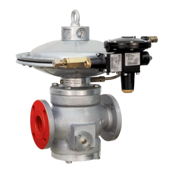
-
Bookmarks
Quick Links
Reval 182
Medium-low pressure gas regulator
Revision 00 — Edition 01/2022
USE, MAINTENANCE
AND WARNING
INSTRUCTIONS
EN
EN
Related Manuals for PIETRO FIORENTINI Reval 182
Summary of Contents for PIETRO FIORENTINI Reval 182
-
Page 1
Reval 182 Medium-low pressure gas regulator Revision 00 — Edition 01/2022 USE, MAINTENANCE AND WARNING INSTRUCTIONS… -
Page 2
MEDIUM PRESSURE REGULATOR INTRODUCTION REV. 00 Use, maintenance and warning instructions… -
Page 3
It is of particular importance that the personnel responsible for the equipment be trained in its use, maintenance and ap- plication of the safety instructions and procedures indicated in this manual. Revision: 00 COPYRIGHT 2022 © PIETRO FIORENTINI S.P.A. MEDIUM PRESSURE REGULATOR INTRODUCTION REV. 00… -
Page 4
MEDIUM PRESSURE REGULATOR INTRODUCTION REV. 00 Use, maintenance and warning instructions… -
Page 5
1.1 — REVISION HISTORY Revision Date Revision contents index 01/2022 Tab. 1.1. MEDIUM PRESSURE REGULATOR INTRODUCTION REV. 00 Use, maintenance and warning instructions… -
Page 6
INDEX 1 — INTRODUCTION ……………………3 1.1 — REVISION HISTORY ……………………..5 2 — GENERAL INFORMATION ………………..13 2.1 — MANUFACTURER IDENTIFICATION ………………….13 2.2 — IDENTIFICATION OF THE PRODUCT …………………. 13 2.3 — REGULATORY FRAMEWORK ……………………. 13 2.4 — WARRANTY ……………………….13 2.5 — SYMBOLS USED IN THE MANUAL …………………. -
Page 7
4 — DESCRIPTION AND OPERATION ………………33 4.1 — GENERAL DESCRIPTION ……………………33 4.1.1 — REGULATOR REACTION MODES ………………….34 4.2 — OPERATION ……………………….34 4.3 — INTENDED USE ……………………….36 4.3.1 — ENVISAGED USE ……………………..36 4.3.2 — REASONABLY FORESEEABLE MISUSE ………………..36 4.3.3 — TYPES OF FLUIDS ……………………..36 4.4 — TECHNICAL FEATURES/PERFORMANCE ……………….. -
Page 8
5.2.5 — REVAL 182 + SB/82 ……………………..64 5.2.6 — REVAL 182 + HB/97 ……………………..65 5.2.7 — REVAL 182 + DB/182 + PM/182 ………………….66 5.2.8 — REVAL 182 + DB/182 + SA ……………………68 5.2.9 — REVAL 182 + DB/182 + SB/82 ………………….70 5.2.10 — REVAL 182 + DB/182 + HB/97 ………………….72… -
Page 9
8.9 — CHECKING THE SA SLAM-SHUT VALVE FOR SEALING DURING SHUT-OFF ……..106 8.9.1 — CALIBRATION PROCEDURE FOR PRESSURE SWITCHES MOD. SA ……….108 8.10 — COMMISSIONING PROCEDURE FOR THE REVAL 182 REGULATOR WITH BUILT-IN SLAM-SHUT VALVE SB/82 …………………………110 8.10.1 — CHECKING THE SB/82 SLAM-SHUT VALVE TIGHTNESS DURING SHUT-OFF ……..110 8.10.2 — CALIBRATION PROCEDURE FOR PRESSURE SWITCHES MOD. -
Page 10
9.4 — ROUTINE MAINTENANCE PROCEDURES ……………….. 127 9.4.1 — TIGHTENING TORQUES REVAL 182 ………………..128 9.4.2 — REPLACING ELEMENTS SUBJECT TO WEAR AND ABRASION…………165 9.4.3 — REGULATOR MAINTENANCE PROCEDURE REVAL 182 …………..166 9.4.4 — DB/182 SILENCER MAINTENANCE ………………..216 9.4.5 — PM 182 INCORPORATED MONITOR ………………..224 9.4.6 — 200/A SERIES PILOT MAINTENANCE + PRE-REGULATORS R31/A AND R14/A …….254… -
Page 11
11 — UNINSTALLATION AND DISPOSAL …………….395 11.1 — GENERAL SAFETY WARNINGS ………………….395 11.2 — QUALIFICATION OF THE OPERATORS IN CHARGE …………….395 11.3 — UNINSTALLATION ……………………..395 11.4 — INFORMATION REQUIRED IN CASE OF RE-INSTALLATION …………..395 11.5 — DISPOSAL INFORMATION ……………………396 12 — RECOMMENDED SPARE PARTS ………………. -
Page 12
MEDIUM PRESSURE REGULATOR INTRODUCTION REV. 00 Use, maintenance and warning instructions… -
Page 13
PIETRO FIORENTINI S.P.A., with registered offices in Arcugnano (Italy) — Via E. Fermi, 8/10, declares under its sole respon- sibility that the equipment of the Reval 182 series described in this manual is designed, manufactured, tested and checked in compliance with the requirements of EN 334 standard on gas pressure regulators. -
Page 14
2.5 — SYMBOLS USED IN THE MANUAL Symbol Definition Symbol used to identify important warnings for the safety of the operator and/or equipment. Symbol used to identify information of particular importance in the instruction manual. The information may also concern the safety of the personnel involved in using the equipment. Obligation to consult the instruction manual/booklet. -
Page 15
Keep the instruction manual near the equipment, in an accessible place known by all qualified technicians involved in using and running it. PIETRO FIORENTINI S.p.A. shall not be held liable for any damage to people, animals and property caused by failure to adhere to the warnings and operating procedures described in this instruction manual. -
Page 16
Removing nameplates and/or replacing them with other plates is strictly not allowed. Should the plates be unintentionally damaged or removed, the customer must notify PIETRO FIORENTINI S.p.A. The equipment and its accessories are provided with nameplates (from Id.1 to Id.8). -
Page 17
Type Image NAMEPLATE MONITOR NAMEPLATE SLAM-SHUT VALVE NAMEPLATE PRESSURE SWITCH NAMEPLATE ACCELERATING VALVE Tab. 2.5. MEDIUM PRESSURE REGULATOR GENERAL INFORMATION REV. 00 Use, maintenance and warning instructions… -
Page 18
2.8.1 — GLOSSARY FOR NAMEPLATES Table 2.6 describes the terms and abbreviations used on identification plates: Term Description Accuracy class. Slam-shut valve accuracy class due to pressure increase. AG max “OPSO” (Overpressure shut-off). Slam-shut valve accuracy class due to pressure decrease. AG min ”UPSO”(Underpressure shut off). -
Page 19
Term Description Full setpoint range with regard to tripping caused by decreased pressure in the pressure switch incorporated in the slam-shut valve. This range can be obtained by adjusting and/or replacing the components (for example, spring or sensitive element). Full setpoint range with regard to tripping caused by decreased pressure in the pressure switch Wdsu built in the slam-shut valve. -
Page 20
2.9 — GLOSSARY OF MEASUREMENT UNITS Type of measurement Unit of measurement Description Stm³/h Standard cubic metres per hour Volumetric flow rate Scfh Standard cubic feet per hour Unit of measurement in the CGS system Pounds per square inch Pressure “wc inch of water column Pascal… -
Page 21
2.10 — QUALIFIED PROFESSIONAL FIGURES Qualified operators in charge of using and managing the equipment throughout its technical service life: Professional figure Definition Qualified technician able to: • perform preventive/corrective maintenance operations on all mechanical parts of the Mechanical equipment subject to maintenance or repair; maintenance techni- •… -
Page 22
MEDIUM PRESSURE REGULATOR GENERAL INFORMATION REV. 00 Use, maintenance and warning instructions… -
Page 23
3 — SAFETY 3.1 — GENERAL SAFETY WARNINGS WARNING! The equipment described in this instruction manual is: • a device subjected to pressure in pressurised systems; • normally installed in systems carrying flammable gases (for example: natural gas). WARNING! If the gas used is a combustible gas, the installation area of the equipment is defined as a “danger zone” as there are residual risks that potentially explosive atmospheres may be generated. -
Page 24
3.2 — PERSONAL PROTECTIVE EQUIPMENT Table 3.9 shows the personal protective equipment (PPE) and its description. An obligation is associated with each symbol. Personal protective equipment means any equipment intended to be worn by the worker in order to protect them against one or several risks that are likely to threaten their safety or health during work. -
Page 25
3.3 — RESIDUAL RISKS In accordance with the requirements of PED 2014/68/EU, point 1.2 of Annex I, below is an assessment of the risks as- sociated with the equipment and an indication of the principles adopted for their prevention, according to the following classification: a) Elimination and/or reduction of the risk. -
Page 26
3.3.1 — TABLE SHOWING RESIDUAL RISKS DUE TO PRESSURE Effect and Risk and hazard Event and cause Solution and prevention consequence Pressurised gas a. Handling and installation with appropri- leakage. • Violent impact; • Deformation; ate devices to avoid localised stress. Projection of me- •… -
Page 27
Effect and Risk and hazard Event and cause Solution and prevention consequence Pressurised gas • Deformation; leakage. a. With the exclusion of what is set out in • Cracking and slot Projection of • External loads bear- the project, the user must verify that no formation;… -
Page 28
3.3.2 — TABLE OF RESIDUAL RISKS FOR POTENTIALLY EXPLOSIVE ATMOSPHERES Table 3.11 shows the conditions that can lead to the generation of a potentially explosive atmosphere respectively for: • of pressure regulator REVAL 182; • of the PM/182 monitor; •… -
Page 29
Atmosphere Management measures in- Operating potentially Regulatory references cluded in the instructions for conditions explosive use and warning This event must be considered a rare malfunction. Breakage of the All atmospheric pressure chambers The instructions for use indicate control head dia- delimited on at least one side by a the need to meet the requirements phragm… -
Page 30
3.4 — OBLIGATIONS AND PROHIBITIONS The following is a list of obligations and prohibitions to be observed for the safety of the operator. It is mandatory to: • carefully read and understand the instructions for use and warning; • check whether the downstream equipment is suitably sized according to the performance required of the regulator in the actual operating condition;… -
Page 31
Depending on the operating conditions, use and configuration required, the equipment may generate noise beyond the limits allowed by current legislation in the country of installation. For the value of the noise generated by the equipment and further information, contact PIETRO FIORENTINI S.p.A. ATTENTION! -
Page 32
MEDIUM PRESSURE REGULATOR SAFETY REV. 00 Use, maintenance and warning instructions… -
Page 33
4 — DESCRIPTION AND OPERATION 4.1 — GENERAL DESCRIPTION The equipment REVAL 182 is a piloted pressure regulator for medium and low pressure which reduces the inlet gas pres- sure, keeping the downstream value stable even when the following varies: •… -
Page 34
4.1.1 — REGULATOR REACTION MODES The REVAL 182 equipment is a regulator controlled with a “fail close” reaction (on-closure reaction), that is, it closes in the event of: • breakage of main diaphragm: • breakage of pilot 204/A diaphragm; •… -
Page 35
In depressurised conditions, the plug (7) is kept in a shut-off position by the spring (9) and rests on the reinforced gasket (6). The upstream pressure (Pu), although variable, does not change this position since the plug is fully balanced. The upstream pressure (Pu) passes through the hole (A) in the stem (10) into the chamber (C). -
Page 36
If no written approval is provided, use shall be considered improper. In the event of “improper use”, PIETRO FIORENTINI S.p.A. shall not be held liable for any damage caused to people or property, and any type of warranty on the equipment shall be deemed void. -
Page 37
4.4 — TECHNICAL FEATURES/PERFORMANCE The equipment REVAL 182 is a regulator for medium and low pressure. The regulation system is balanced and guarantees a stable outlet pressure even when the inlet pressure varies. The main specifications for this regulator are:… -
Page 38
4.5 — POSSIBLE CONFIGURATIONS The REVAL 182 equipment can have different configurations through the installation of the following accessories: • Incorporated silencer DB/182; • Built-in silencer LDB/171; • Built-in monitor PM/182 (up to DN 8″); • Built-in slam-shut valve SA (DN 1″ to DN 4″);… -
Page 39
4.5.1 — BUILT-IN SILENCER 4.5.1.1 — BUILT-IN SILENCER DB/182 The DB/182 silencer (1) is incorporated in the regulator (2). The DB/182 silencer (1) attenuates the noise generated by the equipment during the rolling process. Noise is absorbed precisely where it is generated, which prevents it from propagating. pstream pressUre ownstream pressUre oaDing pressUre… -
Page 40
4.5.1.2 — SILENCER LDB 171 The LDB/171 silencer (1) is incorporated in the regulator (2). The LDB/171 silencer (1) reduces the noise generated by the equipment during the lamination process. Noise is absorbed precisely where it is generated, which prevents it from propagating. pstream pressUre ownstream pressUre Fig. -
Page 41
The PM/182 monitor (1) is incorporated in the regulator (2). pstream pressUre ownstream pressUre regULator pressUre onitor LoaDing pressUre Fig. 4.5. REVAL 182 with built-in monitor PM/182 MEDIUM PRESSURE REGULATOR DESCRIPTION AND OPERATION REV. 00 Use, maintenance and warning instructions… -
Page 42
4.5.2.1 — BUILT-IN MONITOR The PM/182 monitor (1) is mounted in series directly on the service regulator body (2), converting the equipment into two pressure regulators with a common valve body. The two regulators have the following characteristics: • are governed by two separate pilots; •… -
Page 43
OPERATION OF THE BUILT-IN MONITOR IN STAND-BY CONDITIONS: The PM/182 incorporated monitor (1) is normally open during standard operation as pilot (4) calibration is higher than that of the main regulator’s (2) pilot. The passage of the pre-regulator pressure (Pep) generated by the pre-regulator R31/A (5) through the fully open pilot (4) keeps the built-in monitor PM/182 (1) fully open. -
Page 44
BUILT-IN MONITOR OPERATION IN THE EVENT OF FAILURE OF THE MAIN REGULATOR: pstream pressUre ownstream pressUre regULator pressUre onitor LoaDing pressUre Fig. 4.8. Built-in monitor operation in the event of failure of the main regulator Should the main regulator (2) fail, the PM/182 monitor (1) will trip until balanced adjustment is achieved. If, during operation, the following should occur: Operating conditions Operating consequences… -
Page 45
4.5.2.2 — V/25 AND M/A ACCELERATING VALVES NOTICE! To use the monitor as a safety accessory according to Directive 2014/68/EU ‘PED’, installing V/25 or M/A accelerating valves is recommended. In the event of malfunctions of the main regulator (2), to speed up tripping of built-in monitor PM/182 (1), accelerating valves will be installed •… -
Page 46
Fig. 4.10 shows the M/A accelerating valve. pstream pressUre ownstream pressUre regULator pressUre onitor LoaDing pressUre Fig. 4.10. M/A accelerating valve MEDIUM PRESSURE REGULATOR DESCRIPTION AND OPERATION REV. 00 Use, maintenance and warning instructions… -
Page 47
4.5.3 — SLAM-SHUT VALVE The slam-shut valve is a safety device is used to shut off the gas flow if the pressure value at the control point exceeds the calibration value of the valve itself. The slam-shut valve is incorporated in the main regulator of the equipment and consists of: •… -
Page 48
4.5.3.1 — BUILT-IN SLAM-SHUT VALVE SA The SA built-in slam-shut valve is controlled by pressure switch mod. SA-91, SA-92, SA-93 and can be operated: • by the pressure switch; • manually; • with remote control. The main features of the SA built-in slam-shut valve are: •… -
Page 49
pstream pressUre ownstream pressUre Fig. 4.11. Built-in slam-shut valve SA OPERATION In the control head (C), the downstream pressure (Pd) acts on the diaphragm (6) of the control pressure switch (2), which, integral with the control shaft (8), receives an antagonistic force through the springs (4, 5), which causes the plug (1) on the reinforced gasket (9) to disengage. -
Page 50
4.5.3.2 — SB/82 BUILT-IN SLAM-SHUT VALVE The SB/82 built-in slam-shut valve can be operated: • by the pressure switch; • manually; • with remote control. The main features of the SB/82 built-in slam-shut valve are: • tripping due to downstream pressure increase and/or decrease; •… -
Page 51
Fig. 4.12. REVAL 182 with SB/82 incorporated slam-shut valve OPERATION: The tripping pressure acts on the control element of the control pressure switch (2), which is solidly connected to the stem (5), and receives an antagonistic force through the springs due to maximum (7) and minimum (6) pressure tripping, calibrated to the pre-set values. -
Page 52
4.5.3.3 — HB/97 BUILT-IN SLAM-SHUT VALVE The built-in HB/97 incorporated slam-shut valve can be operated: • by the pressure switch; • manually; • with remote control. The main features of the HB/97 built-in slam-shut valve are: • balanced valve plug; •… -
Page 53
Fig. 4.13. REVAL 182 with HB/97 incorporated slam-shut valve OPERATION: At no pressure, the valve plug (1) is kept in the shut-off position by the spring (10) and rests on the reinforced gasket (11). The upstream pressure (Up) reaches the HP2/2 bypass device (4) and the upper head (A) of the R44/SS regulator (5) to prevent inappropriate resetting of the valve. -
Page 54
4.5.4 — SLAM-SHUT VALVE PRESSURE SWITCHES The pressure switch is a control device consisting of (see Fig. 4.14): Pos. Description Control element. NOTICE! The control element can be a diaphragm or a piston. Stem. Adjustment feeler gauges Spring for maximum pressure tripping. Spring for minimum pressure tripping. -
Page 55
Table 4.30 lists the models of possible pressure switches for this regulator: Model pressure Max [bar] Min [bar] switch 101M 0.02 — 1 0.01 — 0.26 101MH 0.02 — 1 102M 0.2 — 5.5 0.05 — 2.8 102MH 0.2 — 5.5 2.8 — 5.5 103M 2 — 22… -
Page 56
MEDIUM PRESSURE REGULATOR DESCRIPTION AND OPERATION REV. 00 Use, maintenance and warning instructions… -
Page 57
5 — TRANSPORT AND HANDLING 5.1 — SPECIFIC WARNINGS FOR TRANSPORT AND HANDLING NOTICE! Transport and handling must be carried out by personnel: • qualified (specially trained); • who are familiar with accident prevention and workplace safety regulations; • authorised to use lifting equipment; •… -
Page 58
PIETRO FIORENTINI S.p.A.. NOTICE! PIETRO FIORENTINI S.p.A. shall not be liable for any damage to people or property caused by accidents due to failure to comply with the instructions provided in this manual. Table 5.32 shows the types of packaging used: Ref. -
Page 59
MEDIUM PRESSURE REGULATOR TRANSPORT AND HANDLING REV. 00 Use, maintenance and warning instructions… -
Page 60
5.2 — PHYSICAL CHARACTERISTICS OF THE EQUIPMENT 5.2.1 — REVAL 182 (+LDB/171) Ø Fig. 5.15. Physical characteristics REVAL 182 (+LDB/171) Overall dimensions REVAL 182 (+LDB/171) Nominal diameter [mm] Size [inches] 1” 2” 2” 1/2 3” 4” 6” 8” 10” Ø… -
Page 61
5.2.2 — REVAL 182 + DB/182 Ø Fig. 5.16. REVAL 182 + DB/182 physical characteristics REVAL 182 + DB/182 overall dimensions Nominal diameter [mm] Size [inches] 1” 2” 2” 1/2 3” 4” 6” 8” 10” Ø 1050 1262 1120 1250… -
Page 62
5.2.3 — REVAL 182 + PM/182 Ø Ø Fig. 5.17. REVAL 182 + PM/182 physical characteristics REVAL 182 + PM/182 overall dimensions Nominal diameter [mm] Size [inches] 1” 2” 2” 1/2 3” 4” 6” 8” Ø 1300 Connecting pneumatic eØ 10mm x Øi 8mm connections Tab. -
Page 63
5.2.4 — REVAL 182 + SA Ø Fig. 5.18. Physical characteristics REVAL 182 + SA Overall dimensions REVAL 182 + SA Nominal diameter [mm] Size [inches] 1” 2” 2” 1/2 3” 4” Ø Connecting pneumatic eØ 10mm x Øi 8mm connections Tab. -
Page 64
5.2.5 — REVAL 182 + SB/82 Ø Fig. 5.19. Physical characteristics REVAL 182 + SB/82 Overall dimensions REVAL 182 + SB/82 Nominal diameter [mm] Size [inches] 1” 2” 2” 1/2 3” 4” 6” 8” 10” Ø 1125 1320 Connecting pneumatic eØ… -
Page 65
5.2.6 — REVAL 182 + HB/97 Fig. 5.20. Physical characteristics REVAL 182 + HB/97 Overall dimensions REVAL 182 + HB/97 Nominal diameter [mm] Size [inches] 4” 6” 8” 10” Ø C with HB/97 D with HB/97 1060 H with HB/97… -
Page 66
5.2.7 — REVAL 182 + DB/182 + PM/182 Ø Ø Fig. 5.21. REVAL 182 + DB/82 + PM/182 physical characteristics MEDIUM PRESSURE REGULATOR TRANSPORT AND HANDLING REV. 00 Use, maintenance and warning instructions… -
Page 67
REVAL 182 + DB/182 + PM/182 overall dimensions Nominal diameter [mm] Size [inches] 1” 2” 2” 1/2 3” 4” 6” 8” Ø 1050 1120 1250 1020 1055 1165 1410 1640 Connecting pneumatic eØ 10mm x Øi 8mm connections Tab. 5.45. -
Page 68
5.2.8 — REVAL 182 + DB/182 + SA Ø Fig. 5.22. Physical characteristics REVAL 182 + DB/182 + SA MEDIUM PRESSURE REGULATOR TRANSPORT AND HANDLING REV. 00 Use, maintenance and warning instructions… -
Page 69
Overall dimensions REVAL 182 + DB/182 + SA Nominal diameter [mm] Size [inches] 1” 2” 2” 1/2 3” 4” Ø Connecting pneumatic eØ 10mm x Øi 8mm connections Tab. 5.47. REVAL 182 + DB/182 + SA Weight [kgf] Tab. 5.48. -
Page 70
5.2.9 — REVAL 182 + DB/182 + SB/82 Ø Fig. 5.23. Physical characteristics REVAL 182 + DB/182 + SB/82 MEDIUM PRESSURE REGULATOR TRANSPORT AND HANDLING REV. 00 Use, maintenance and warning instructions… -
Page 71
Overall dimensions REVAL 182 + DB/182 + SB/82 Nominal diameter [mm] Size [inches] 1” 2” 2” 1/2 3” 4” 6” 8” 10” Ø 1050 1262 1120 1250 1450 1040 1010 1115 1350 1525 1812 Connecting pneumatic eØ 10mm x Øi 8mm connections Tab. -
Page 72
5.2.10 — REVAL 182 + DB/182 + HB/97 Fig. 5.24. Physical characteristics REVAL 182 + DB/182 + HB/97 MEDIUM PRESSURE REGULATOR TRANSPORT AND HANDLING REV. 00 Use, maintenance and warning instructions… -
Page 73
Overall dimensions REVAL 182 + DB/182 + HB/97 Nominal diameter [mm] Size [inches] 4” 6” 8” 10” Ø 1050 1262 1120 1250 1450 1060 1040 1060 Connecting pneumatic connections Tab. 5.51. REVAL 182 + DB/182 + HB/97 Weight [kgf] Tab. 5.52. -
Page 74
5.3 — EQUIPMENT ANCHORING AND LIFTING METHOD HAZARD! Before moving the equipment, make sure that the capacity of the lifting equipment is suitable for the load. WARNING! Unloading, transport and handling activities must be carried out by operators qualified and specially trained: •… -
Page 75
5.3.1 — FORKLIFT HANDLING METHOD HAZARD! It is forbidden to: • Do not transit under suspended loads; • Do not move the load over the personnel operating in the site/plant area. WARNING! The following is not allowed on forklifts: • carrying passengers;… -
Page 76
Step Action Image Sollevare lentamente il carico di qualche decina di centimetri e veri carne la stabilità facendo attenzio- Inclinare il montante all’indietro (verso il posto guida) per avvantaggiare il momento ribaltante e Adeguare la velocità d ne che il baricentro del carico sia posizionato al centro delle forche di sollevamento. garantire una maggiore stabilità… -
Page 77
5.3.2 — CRANE HANDLING METHOD WARNING! It is mandatory to use CE marked chains, ropes and eyebolts or marked with conformity marks/markings in accordance with the regulations in force in the place of installation. Do not use chains connected to each other by bolts. -
Page 78
• do not install the equipment; • contact PIETRO FIORENTINI S.p.A. and specify the details provided on the equipment nameplate. 5.4.1 — PACKAGING DISPOSAL NOTICE! Sort the various materials making up the packaging and dispose of them in compliance with the regula- tions in force in the country of installation. -
Page 79
To replace the rubber parts of the equipment, please refer to chapter 9 “Maintenance and functional checks”. NOTICE! PIETRO FIORENTINI S.p.A. recommends checking the condition of rubber parts in case of downtime or storage longer than 3 years. MEDIUM PRESSURE REGULATOR TRANSPORT AND HANDLING REV. -
Page 80
MEDIUM PRESSURE REGULATOR TRANSPORT AND HANDLING REV. 00 Use, maintenance and warning instructions… -
Page 81
6 — INSTALLATION 6.1 — INSTALLATION PRE-REQUISITES 6.1.1 — ALLOWED ENVIRONMENTAL CONDITIONS WARNING! To safely use the equipment, in full respect of the allowed environmental conditions, follow the data shown on the regulator plate and on any accessories (refer to paragraph 2.8 “Nameplates applied”). The installation site must be suitable for the safe use of the equipment. -
Page 82
6.1.2 — CHECKS BEFORE INSTALLATION The equipment does not require any further upstream safety device for protection against any overpressure with respect to its PS admissible pressure when, for the upstream reduction station, the maximum incidental downstream pressure MIPd ≤ 1.1 PS MIPd = Maximum incidental downstream pressure value (for further information, see UNI EN 12186:2014). -
Page 83
6.2 — SPECIFIC SAFETY INSTRUCTIONS FOR THE INSTALLATION STEP WARNING! Before proceeding with installation, make sure that the upstream and downstream valves installed on the line are shut off. WARNING! Installation may also take place in areas where there is a risk of explosion, which implies that all necessary prevention and protection measures have to be taken. -
Page 84
6.3 — GENERAL INFORMATION ON CONNECTIONS The equipment must be installed in-line with an arrow on the body pointing to the gas flow direction. In line installation, they must be present (see Fig. 6.25 and 6.26): Pos. Description 1 shut-off valve upstream of the equipment. 2 vent valves one upstream and one downstream of the equipment. -
Page 85
NOTICE! When used in gas pressure reduction stations, the device must be installed at least according to the re- quirements of standards UNI EN 12186:2014 or UNI EN 12279:2007. Equipment vents must be ducted in accordance with UNI EN 12186:2014 or UNI EN 12279:2007 or the standards in force at the place of installation of the equipment. -
Page 86
6.5 — INSTALLATION PROCEDURES 6.5.1 — EQUIPMENT INSTALLATION PROCEDURES Step Action Place the equipment in the section of the line designated for it. Place the gaskets between the line flanges and the regulator flanges. Insert the bolts into the appropriate holes of the connecting flanges. Screw the bolts following the technical rules for tightening flanges. -
Page 87
To calculate the flow rate, use the following formula: 1 − 0,002 = 345,92 V = gas velocity in m/sec Q = gas flow rate Stm³/h DN = nominal diameter of the regulator in mm Pd = regulator outlet pressure in barg NOTICE! All on-site pneumatic connections must have pipes with a minimum internal diameter of 8 mm. -
Page 88
If there is a multiple sensing line, connect the equipment connections as shown below: • 1 and 2 to the exhaust outlet of the regulator head and monitor PM/182 when present; • 3 and 4 to the pilot sensing lines; •… -
Page 89
7 — COMMISSIONING/MAINTENANCE EQUIPMENT 7.1 — LIST OF EQUIPMENT Use of commissioning/maintenance equipment • Mechanical maintenance technician; • Electrical maintenance technician; Operator qualification • Installer; • User’s technician. WARNING! The PPE listed in this table is related to the risk associated with the equipment. PPE required For the PPE required to protect against risks associated with the workplace, installation or operating conditions, please refer to:… -
Page 90
Ref. Equipment type Image T-handle hex socket wrench Phillips screwdriver Slotted screwdriver O-ring extraction tool Circlip pliers Fiorentini special key Fiorentini special key Fiorentini special tool Tab. 7.62. MEDIUM PRESSURE REGULATOR REV. 00 COMMISSIONING AND MAINTENANCE EQUIPMENT Use, maintenance and warning instructions… -
Page 91
Type (size) or code of the equipment. Tab. 7.63. NOTICE! Equipment for DB/182 silencer configurations (see paragraph 5.2) refer to the REVAL 182 + DB/182 equip- ment table (tab. 7.65). If necessary, please refer to the accessories equipment table. REVAL 182 (+LDB/171) Equipment Ref. -
Page 92
REVAL 182 + DB/182 Equipment Ref. Type 1” 2” 2” 1/2 3” 4” 6” 8” 10” 10-16-17- 10-16-17- 10-16-17- 10-16-17- 10-16-17- 10-16-17- 10-16-17- 10-16-17- K./Wr. 18-19-22- 18-19-22- 18-19-22- 18-19-22- 18-19-22- 18-19-22- 18-19-22- 18-19-24- 24-27-30 24-27-30 24-27-30 24-27-30 24-27-41 24-27-41 24-27-41 30-32-55 Ø… -
Page 93
REVAL 182 + SA Equipment Ref. Type 1” 2” 2” 1/2 3” 4” Ø K./Wr. K./Wr. 2.5-8 2.5-8 2.5-8 2.5-8 2.5-8 K./Wr. 4-5-8 4-5-8 4-5-8 4-5-8 4-5-8 65×100 Code 7999099 Tab. 7.67. REVAL 182 + SB/82 Equipment Ref. Type 1”… -
Page 94
REVAL 182 + HB/97 Equipment Ref. Type 4” 6” 8” 10” 10-16-17-18-19-22- 10-16-17-18-19-22- 10-16-17-18-19-22- 7-10-16-17-19-24-30- K./Wr. 24-27-41 24-27-41 24-27-41 55-57 Ø K./Wr. 24-27-41 24-27-41 17-27-30-55 K./Wr. 2.5-8 2.5-8 2.5-8 4-5-8 K./Wr. 4-5-8 4-5-8 4-5-8 10-17 6.5 x 100 Code 7999099 Ø… -
Page 95
8 — COMMISSIONING 8.1 — GENERAL WARNINGS 8.1.1 — SAFETY REQUIREMENTS FOR COMMISSIONING HAZARD! During commissioning the risks associated with any discharges to the atmosphere of flammable or nox- ious gases must be evaluated. HAZARD! In case of installation on distribution networks for natural gas, consider the risk associated with explosive mixtures (gas/air) being formed inside the piping, if the line is not subjected to inerting. -
Page 96
8.2 — PRELIMINARY PROCEDURES FOR COMMISSIONING HAZARD! Before commissioning the equipment, it must be ensured that any source of explosion has been eliminated if there is such a danger. WARNING! Before commissioning, you need to make sure that the characteristics of the equipment are suitable for the conditions of use. -
Page 97
8.3 — PROPER COMMISSIONING CHECK Completely sprinkle the equipment with a foaming solution in order to check the tightness of the regulator’s external sur- faces and of the connections made during installation (or equivalent control system). 8.4 — CALIBRATION OF EQUIPMENT AND ACCESSORIES INSTALLED NOTICE! To properly calibrate the equipment and accessories present, refer to the accuracy class indicated on the nameplates (see section 2.8). -
Page 98
In the application consisting of two pressure adjusting lines, it is advisable to commission one line at a time, starting with the line with the lowest set point. The set point value is mentioned on the test certificate enclosed with each piece of equipment. Fig. 8.32. Commissioning the regulator REVAL 182 MEDIUM PRESSURE REGULATOR COMMISSIONING REV. 00… -
Page 99
Step Action Partially open the drain cock (6). Completely unscrew the fixing nut and adjusting screw (fig. 8.43) of the pilot (3) to relieve the spring. Open the inlet shut-off valve (V1) very slowly. NOTICE! Check the pressure by referring to the pressure gauge (4) located upstream. Turn the pilot adjustment screw (3) clockwise to load the setting spring until the regulator (1) trips. -
Page 100
8.6 — COMMISSIONING PROCEDURE FOR THE REGULATOR REVAL 182 WITH PM 182 INCORPORATED MONITOR Fig. 8.33. Procedure for commissioning the regulator REVAL 182 with PM/182 built-in monitor Step Action Partially open the drain cock (6). Completely unscrew the nut securing the adjusting screws (fig. 8.43) of the pilots (3, 10). -
Page 101
Step Action Turn the adjusting screw (fig. 8.43) on the pilot (3) anti-clockwise to relieve the setting spring until the regulator trips. Make sure that the PM/182 monitor (8) is fully open (100%) by checking the position of the stroke indicator rod (fig. -
Page 102
8.7 — COMMISSIONING PROCEDURE FOR THE REGULATOR REVAL 182 WITH BUILT-IN PM/182 MONITOR AND V/25 ACCELERATING VALVE Fig. 8.34. Commissioning of the REVAL 182 regulator with built-in monitor PM/182 and V/25 accelerating valve Step Action Partially open the drain cock (6). -
Page 103
Step Action Turn the adjustment ring nut (Fig. 8.42) of the V/25 accelerating valve (11) anti-clockwise to decrease the set- ting of the cut-in pressure value until a gas discharge from the gas outlet is detected. NOTICE! Check for sealing with a foaming substance. Turn the adjusting screw (fig. -
Page 104
8.8 — COMMISSIONING PROCEDURE FOR THE REGULATOR REVAL 182 WITH BUILT-IN PM/182 MONITOR AND M/A ACCELERATING VALVE Fig. 8.35. Commissioning of the REVAL 182 regulator with built-in PM/182 monitor and M/A accelerating valve Step Action Partially open the drain cock (6). -
Page 105
Step Action Turn the adjusting screw of the M/A accelerating valve (11) anti-clockwise to decrease the setting of the cut- in pressure value until gas is released from the gas outlet. NOTICE! Check for sealing with a foaming substance. Turn the adjusting screw (fig. 8.43) of the monitor pilot (10) anti-clockwise to decrease the value of the down- stream pressure to the selected monitor operating value. -
Page 106
8.9 — CHECKING THE SA SLAM-SHUT VALVE FOR SEALING DURING SHUT-OFF Fig. 8.36. Commissioning of the regulator REVAL 182 with SA slam-shut valve Step Action Check that the slam-shut valve is in the shut-off position. Open the drain cock (6) and drain the downstream section completely. -
Page 107
MEDIUM PRESSURE REGULATOR COMMISSIONING REV. 00 Use, maintenance and warning instructions… -
Page 108
8.9.1 — CALIBRATION PROCEDURE FOR PRESSURE SWITCHES MOD. SA Fig. 8.37. Calibration of pressure switches mod. SA SPRING CALIBRATION FOR MAXIMUM PRESSURE TRIP Step Action Increase the downstream pressure to the slam-shut valve’s cut-out value by turning the main regulator’s pilot adjustment screw to check that the setting is correct. -
Page 109
SPRING CALIBRATION FOR MINIMUM PRESSURE TRIP (IF ANY) Step Action Partially open the drain cock (fig. 8.32, ref. 6) to the atmosphere and keep it open for the next steps. Decrease the downstream pressure to the minimum required slam-shut device pressure by turning the main regulator’s pilot adjustment screw. -
Page 110
8.10 — COMMISSIONING PROCEDURE FOR THE REVAL 182 REGULATOR WITH BUILT-IN SLAM-SHUT VALVE SB/82 8.10.1 — CHECKING THE SB/82 SLAM-SHUT VALVE TIGHTNESS DURING SHUT-OFF Fig. 8.38. Sealing of the SB/82 slam-shut valve during shut-off Step Action Check that the slam-shut valve is in the shut-off position. -
Page 111
MEDIUM PRESSURE REGULATOR COMMISSIONING REV. 00 Use, maintenance and warning instructions… -
Page 112
8.10.2 — CALIBRATION PROCEDURE FOR PRESSURE SWITCHES MOD. 100 Fig. 8.39. Calibration of pressure switches mod. 100 SPRING CALIBRATION FOR MAXIMUM PRESSURE TRIP Step Action Increase the downstream pressure to the slam-shut valve’s cut-out value by turning the main regulator’s pilot adjustment screw to check that the setting is correct. -
Page 113
SPRING CALIBRATION FOR MINIMUM PRESSURE TRIP (IF ANY) Step Action Partially open the drain cock (fig. 8.32, ref. 6) to the atmosphere and keep it open for the next steps. Decrease the downstream pressure to the minimum required slam-shut device pressure by turning the main regulator’s pilot adjustment screw. -
Page 114
8.11 — COMMISSIONING PROCEDURE FOR THE REGULATOR REVAL 182 WITH HB/97 SLAM-SHUT VALVE 8.11.1 — CHECKING THE SB/97 SLAM-SHUT VALVE FOR SEALING DURING SHUT-OFF Fig. 8.40. Sealing of the HB/ 97 slam-shut valve during shut-off Step Action Check that the slam-shut valve is in the shut-off position. -
Page 115
MEDIUM PRESSURE REGULATOR COMMISSIONING REV. 00 Use, maintenance and warning instructions… -
Page 116
8.11.2 — COMMISSIONING PROCEDURE AND CALIBRATION OF THE LINE OFF 2.0 DEVICE FOR SLAM-SHUT VALVE HB/97 Fig. 8.41. Commissioning and calibration of LINE OFF 2.0 for HB/97 slam-shut valve MEDIUM PRESSURE REGULATOR COMMISSIONING REV. 00 Use, maintenance and warning instructions… -
Page 117
Step Action Press and hold the button of the bypass valve HP2/2 (7.1) to: • bring the upstream pressure to the power supply unit of the LINE-OFF 2.0 device; • balance the pressure of the HB/97 built-in slam-shut valve plug. Release the button of bypass valve HP2/2 (7.1) after checking that the upstream and downstream pressure of the slam-shut valve is balanced. -
Page 118
8.13 — DEVICE CALIBRATION 8.13.1 — V/25 ACCELERATING VALVE CALIBRATION Fig. 8.42. V/25 Accelerating valve calibration Adjust the adjustment ring nut (23): • anticlockwise to decrease the adjusted pressure; • clockwise to increase the adjusted pressure. 8.13.2 — CALIBRATION 200/A SERIES PILOTS AND M/A ACCELERATING VALVE Fig. -
Page 119
8.13.3 — CALIBRATION OF PRESSURE SWITCHES MOD. 100 Fig. 8.44. Calibration of pressure switches mod. 100 Adjust the maximum pressure (11) ring nut (13): • anti-clockwise to decrease the slim-shut device tripping pressure; • clockwise to increase the slim-shut device tripping pressure. Turn the minimum pressure (17) ring nut (15): •… -
Page 120
8.13.4 — PRESSURE SWITCH CALIBRATION MOD. SA Fig. 8.45. Calibration of pressure switches mod. SA Adjust the maximum pressure (11) ring nut (13): • anti-clockwise to decrease the slim-shut device tripping pressure; • clockwise to increase the slim-shut device tripping pressure. Turn the minimum pressure (17) ring nut (15): •… -
Page 121
WARNING! In case of doubt, do not perform any work. Contact PIETRO FIORENTINI S.p.A. for the necessary clarifications. Managing and/or using the equipment includes operations that are necessary as a result of normal use such as: •… -
Page 122
Before beginning disassembly of the equipment, make sure that: • the spare parts and parts used in replacements have adequate requirements to ensure the original performance of the equipment. Use original, compliant spare parts; • the operator has the necessary equipment (see chapter 7 “Equipment for commissioning/maintenance”). NOTICE! The recommended spare parts are unambiguously identified with tags indicating: •… -
Page 123
9.2 — PERIODICALLY CHECKING AND INSPECTING THE EQUIPMENT FOR PROPER OPERATION Periodic checks and inspections Operator qualification Mechanical maintenance technician WARNING! The PPE listed in this table is related to the risk associated with the equipment. PPE required For the PPE required to protect against risks associated with the workplace, installation or operating conditions, please refer to: •… -
Page 124
9.3 — ROUTINE MAINTENANCE 9.3.1 — GENERAL SAFETY WARNINGS HAZARD! • Put the equipment in a safe condition (close the downstream shut-off valve and then the upstream one, and drain the line completely); • ensure that the pressure upstream and downstream of the equipment is “0”. NOTICE! Before installing new sealing elements (o-rings, diaphragm, etc.), they must be checked for integrity. -
Page 125
9.3.2 — REPLACEMENT FREQUENCY FOR COMPONENTS SUBJECT TO WEAR NOTICE! The following provisions shall apply to equipment components only. The non-metallic parts of the equipment concerned are divided into the following two categories: Preventive maintenance work Parts subject to wear and/or abrasion, where: •… -
Page 126
Minimum Category Part description Evaluation criterion replacement frequency Relief valves 6 years Non-metallic parts of equipment with an in- ternal sealing function: under normal oper- If there are Regulation lines disconnection equipment ating conditions during maintenance proven leaks Non-metallic parts with a static sealing If there are Various equipment function only… -
Page 127
9.4 — ROUTINE MAINTENANCE PROCEDURES Routine maintenance Operator qualification Mechanical maintenance technician WARNING! The PPE listed in this table is related to the risk associated with the equipment. PPE required For the PPE required to protect against risks associated with the workplace, installation or operating conditions, please refer to: •… -
Page 128
9.4.1 — TIGHTENING TORQUES REVAL 182 REVAL 182 1”-2” Fig. 9.46. Tightening torques REVAL 182 MEDIUM PRESSURE REGULATOR MAINTENANCE AND FUNCTIONAL CHECKS REV. 00 Use, maintenance and warning instructions… -
Page 129
Screw M10X25 UNI 5739 Screw M10X20 UNI 5739 Screw M6X14 UNI 5931 Screw M6X12 UNI 5931 Screw M12X35 UNI 5739 Tab. 9.91. REVAL 182 DN 2” 1/2 Pos. Description Torque (Nm) Torque (ft — lb) M12 piston guide Screw M10X25 UNI 5739… -
Page 130
REVAL 182 1”-2” Tightening torques REVAL 182 MEDIUM PRESSURE REGULATOR MAINTENANCE AND FUNCTIONAL CHECKS REV. 00 Use, maintenance and warning instructions… -
Page 131
REVAL 182 DN 4” Pos. Description Torque (Nm) Torque (ft — lb) M12 piston guide Screw M10X25 UNI 5739 Screw M10X20 UNI 5739 Screw M6X14 UNI 5931 Screw M6X16 UNI 5931 Screw M16X50 UNI 5737 Screw M16X50 UNI 5737 Tab. 9.94. -
Page 132
9.4.1.1 — TIGHTENING TORQUES REVAL 182 + SILENCER DB/182 REVAL 182 1”-2” Fig. 9.47. Tightening torques REVAL 182 + Silencer DB/182 MEDIUM PRESSURE REGULATOR MAINTENANCE AND FUNCTIONAL CHECKS REV. 00 Use, maintenance and warning instructions… -
Page 133
REVAL 182 DN 1” + DB/182 Pos. Description Torque (Nm) Torque (ft — lb) Nut M12 M12 piston guide Screw M10X25 UNI 5739 Screw M10X20 UNI 5739 Screw M6X14 UNI 5931 Screw M6X12 UNI 5931 Screw M10X30 UNI 5739 Screw M10X35 UNI 5931… -
Page 134
REVAL 182 1”-2” Tightening torques REVAL 182 + Silencer DB/182 MEDIUM PRESSURE REGULATOR MAINTENANCE AND FUNCTIONAL CHECKS REV. 00 Use, maintenance and warning instructions… -
Page 135
REVAL 182 DN 2” 1/2 + DB/182 Pos. Description Torque (Nm) Torque (ft — lb) M12 piston guide Screw M10X25 UNI 5739 Screw M10X20 UNI 5739 Screw M6X14 UNI 5931 Screw M6X16 UNI 5931 Screw M12X40 UNI 5739 Nut M12 UNI 5589… -
Page 136
REVAL 182 1”-2” Tightening torques REVAL 182 + Silencer DB/182 MEDIUM PRESSURE REGULATOR MAINTENANCE AND FUNCTIONAL CHECKS REV. 00 Use, maintenance and warning instructions… -
Page 137
REVAL 182 DN 4” + DB/182 Pos. Description Torque (Nm) Torque (ft — lb) M12 piston guide Screw M10X25 UNI 5739 Screw M10X20 UNI 5739 Screw M6X14 UNI 5931 Screw M6X16 UNI 5931 Screw M16X50 UNI 5737 Nut M12 UNI 5589… -
Page 138
REVAL 182 1”-2” Tightening torques REVAL 182 + Silencer DB/182 MEDIUM PRESSURE REGULATOR MAINTENANCE AND FUNCTIONAL CHECKS REV. 00 Use, maintenance and warning instructions… -
Page 139
REVAL 182 DN 8” + DB/182 Pos. Description Torque (Nm) Torque (ft — lb) Piston guide M18 Screw M10X25 UNI 5739 Screw M14X25 UNI 5739 Screw M6X16 UNI 5931 Screw M6X16 UNI 5931 Screw M14X55 UNI 5737 Nut M18 UNI 5589… -
Page 140
9.4.1.2 — TIGHTENING TORQUES FOR PM/182 BUILT-IN MONITOR REVAL 182 1”-2” Fig. 9.48. Tightening torques for PM/182 built-in monitor MEDIUM PRESSURE REGULATOR MAINTENANCE AND FUNCTIONAL CHECKS REV. 00 Use, maintenance and warning instructions… -
Page 141
PM/182 DN 1” Pos. Description Torque (Nm) Torque (ft — lb) Nut M12 M12 piston guide Screw M10X25 UNI 5739 Screw M10X20 UNI 5739 Screw M6X14 UNI 5931 Screw M6X12 UNI 5931 Screw M10X30 UNI 5739 Tab. 9.106. PM/182 DN 2” Pos. -
Page 142
REVAL 182 1”-2” Tightening torques for PM/182 built-in monitor MEDIUM PRESSURE REGULATOR MAINTENANCE AND FUNCTIONAL CHECKS REV. 00 Use, maintenance and warning instructions… -
Page 143
PM/182 DN 4” Pos. Description Torque (Nm) Torque (ft — lb) M12 piston guide Screw M10X25 UNI 5739 Screw M10X20 UNI 5739 Screw M6X14 UNI 5931 Screw M6X16 UNI 5931 Screw M16X50 UNI 5739 Tab. 9.110. PM/182 DN 6” Pos. Description Torque (Nm) Torque (ft — lb) -
Page 144
9.4.1.3 — TIGHTENING TORQUES 200/A SERIES PILOTS Fig. 9.49. Tightening torques for 201/A pilot PILOTS 201/A Pos. Description Torque (Nm) Torque (ft — lb) Nut M16X1 Screw M6X25 UNI 5931 Screw M8X30 UNI 5931 Nut M16x1.5 Nut M16x1.5 Nut M20x1 Tab. -
Page 145
Fig. 9.50. Tightening torques for 204/A pilot PILOTS 204/A Pos. Description Torque (Nm) Torque (ft — lb) Nut M16X1 Screw M8X30 UNI 5931 Nut M16X1.5 Nut M18X1.5 Tab. 9.114. MEDIUM PRESSURE REGULATOR MAINTENANCE AND FUNCTIONAL CHECKS REV. 00 Use, maintenance and warning instructions… -
Page 146
9.4.1.4 — PRE-REGULATOR TIGHTENING TORQUES Fig. 9.51. Pre-regulator R31/A tightening torques PRE-REGULATOR R31/A Pos. Description Torque (Nm) Torque (ft — lb) Nut M6x25 UNI 5931 Nut M8 UNI 5588 Tab. 9.115. MEDIUM PRESSURE REGULATOR MAINTENANCE AND FUNCTIONAL CHECKS REV. 00 Use, maintenance and warning instructions… -
Page 147
Fig. 9.52. Pre-regulator R14/A tightening torques PRE-REGULATOR R14/A Pos. Description Torque (Nm) Torque (ft — lb) Nut M8x30 UNI 5931 Nut M8 UNI 5588 Tab. 9.116. MEDIUM PRESSURE REGULATOR MAINTENANCE AND FUNCTIONAL CHECKS REV. 00 Use, maintenance and warning instructions… -
Page 148
9.4.1.5 — TIGHTENING TORQUE SA SLAM-SHUT VALVE Fig. 9.53. SA slam-shut valve tightening torques MEDIUM PRESSURE REGULATOR MAINTENANCE AND FUNCTIONAL CHECKS REV. 00 Use, maintenance and warning instructions… -
Page 149
SA DN 1” Pos. Description Torque (Nm) Torque (ft — lb) Screw M6X12 UNI 5931 Screw M5X16 UNI 5931 Screw M6X12 UNI 5931 Tab. 9.117. SA DN 2” Pos. Description Torque (Nm) Torque (ft — lb) Screw M6X12 UNI 5931 Screw M5X16 UNI 5931 Screw M6X12 UNI 5931 Tab. -
Page 150
9.4.1.6 — TIGHTENING TORQUE CONTROL PRESSURE SWITCH SA-91, SA-92, SA-93 SA/91 SA/92 SA-93 Fig. 9.54. Tightening torques locking mechanism SA-91, SA-92, SA-93 MEDIUM PRESSURE REGULATOR MAINTENANCE AND FUNCTIONAL CHECKS REV. 00 Use, maintenance and warning instructions… -
Page 151
SA/91 Pos. Description Torque (Nm) Torque (ft — lb) Slam-shut device guide Screw M5X10 UNI 5931 Screw M5X20 UNI 5931 Screw M5X10 UNI 5933 Tab. 9.122. SA/92 Pos. Description Torque (Nm) Torque (ft — lb) Slam-shut device guide Screw M5X10 UNI 5931 Screw M5X20 UNI 5931 Screw M5X10 UNI 5933 Tab. -
Page 152
9.4.1.7 — SLAM-SHUT VALVE TIGHTENING TORQUES SB/82 Fig. 9.55. Tightening torques slam-shut valve SB/82 DN 1″ SB/82 DN 1” Pos. Description Torque (nm) Torque (ft — lb) Safety valve screw M10 Screw M6X12 UNI 5931 Screw M6X20 UNI 5931 Screw M6X20 UNI 5931 Screw M12X45 UNI 5931 Screw M10X25 UNI 5931 Screw M6X20 UNI 5931… -
Page 153
Fig. 9.56. Tightening torques slam-shut valve SB/82 DN 2″ SB/82 DN 2” Pos. Description Torque (nm) Torque (ft — lb) Safety valve screw M10 Screw M6X12 UNI 5931 Screw M6X20 UNI 5931 Screw M6X20 UNI 5931 Screw M6X20 UNI 5931 Screw M12X45 UNI 5931 Tab. -
Page 154
Fig. 9.57. Tightening torques slam-shut valve SB/82 DN 2″ 1/2 to 4″ SB/82 DN 2” 1/2 Pos. Description Torque (nm) Torque (ft — lb) Safety valve screw M10 Screw M12X40 UNI 5739 Screw M6X12 UNI 5931 Screw M6X20 UNI 5931 Screw M6X20 UNI 5931 Screw M6X20 UNI 5931 Nut M12 UNI 5588… -
Page 155
Fig. 9.58. Tightening torques slam-shut valve SB/82 DN 2″ 1/2 to 4″ SB/82 DN 3” Pos. Description Torque (nm) Torque (ft — lb) Safety valve screw M10 Screw M12X40 UNI 5739 Screw M6X12 UNI 5931 Screw M6X20 UNI 5931 Screw M6X20 UNI 5931 Screw M6X20 UNI 5931 Nut M12 UNI 5588 Tab. -
Page 156
Fig. 9.59. Tightening torques slam-shut valve SB/82 DN 6″-8″ SB/82 DN 6” Pos. Description Torque (nm) Torque (ft — lb) Safety valve screw Screw M14X50 UNI 5737 Screw M6X16 UNI 5931 Screw M6X10 UNI 5931 Screw M8X25 UNI 5931 Screw M6X40 UNI 5931 Screw M6X20 UNI 5931 Nut M14 UNI 5588 Tab. -
Page 157
Fig. 9.60. Tightening torques slam-shut valve SB/82 DN 10″ SB/82 DN 10” Pos. Description Torque (nm) Torque (ft — lb) Screw M16X90 UNI 5737 Screw M6X16 UNI 5931 Nut M20 UNI 5589 Screw M6X20 UNI 5931 Screw M8X25 UNI 5931 Screw M6X35 UNI 5931 Screw M6X20 UNI 5931 Tab. -
Page 158
9.4.1.8 — TIGHTENING TORQUES OF THE HB/97 SLAM-SHUT VALVE WITH LINE OFF 2.0 4” 6”÷10” Fig. 9.61. Slam-shut valve tightening torques HB/97 HB/97 DN 4” Pos. Description Torque (nm) Torque (ft — lb) Locking nut M12X1.25 M12X1.25 balancing piston guide Screw M10X40 UNI 5737 Nut M12X1.25 UNI 5589 Nut M12 UNI 5588… -
Page 159
Pos. Description Torque (nm) Torque (ft — lb) Locking nut M24X1.5 M18X1.5 balancing piston guide Screw M14X50 UNI 5737 Nut M18X1.5 UNI 5589 Nut M16 UNI 5588 Screw M8X20 UNI 5931 Screw M6X25 UNI 5931 Screw M6X16 UNI 5931 Tab. 9.135. HB/97 DN 10”… -
Page 160
9.4.1.9 — TIGHTENING TORQUES PRESSURE SWITCHES MOD. 100 MOD. 102M/102MH MOD. 101M/101MH MOD. 103M/103MH Fig. 9.62. Tightening torques pressure switches mod.100 MEDIUM PRESSURE REGULATOR MAINTENANCE AND FUNCTIONAL CHECKS REV. 00 Use, maintenance and warning instructions… -
Page 161
MOD. 101M/101MH Pos. Description Torque (nm) Torque (ft — lb) Screw M4X10 UNI 5931 Screw M5X10 UNI 5933 Screw M6X16 UNI 5931 Nut M6 UNI 5588 Screw M5X15 UNI 8112 Screw M6X25 UNI 5931 Screw M5X10 UNI 5933 Screw M5X16 UNI 5931 Tab. -
Page 162
9.4.1.10 — TIGHTENING TORQUES FOR HP2/2 BYPASS DEVICE Fig. 9.63. Tightening torques for HP2/2 bypass device HP2/2 Pos. Description Torque (Nm) Torque (ft — lb) Screw M8X20 UNI 5931 Screw M8X45 UNI 5931 Tab. 9.140. MEDIUM PRESSURE REGULATOR MAINTENANCE AND FUNCTIONAL CHECKS REV. -
Page 163
9.4.1.11 — TIGHTENING TORQUES FOR LAMINATION VALVE AR100 Fig. 9.64. Tightening torques for lamination valve AR100 LAMINATION VALVE AR100 Pos. Description Torque (Nm) Torque (ft — lb) Cap M20X1.5 Screw M8 Tab. 9.141. MEDIUM PRESSURE REGULATOR MAINTENANCE AND FUNCTIONAL CHECKS REV. -
Page 164
9.4.1.12 — TIGHTENING TORQUES FOR R44/SS REGULATOR 24.1 Fig. 9.65. Tightening torques for R44/SS regulator R44/SS Pos. Description Torque (Nm) Torque (ft — lb) Nut M16X1 Screw M8X110 UNI 5931 24.1 Screw M8X70 UNI 5931 Nut M16X1.5 Nut M18X1.5 Tab. 9.142. MEDIUM PRESSURE REGULATOR MAINTENANCE AND FUNCTIONAL CHECKS REV. -
Page 165
9.4.2 — REPLACING ELEMENTS SUBJECT TO WEAR AND ABRASION 9.4.2.1 — INITIAL OPERATIONS ATTENTION! Before carrying out any work, it is important to ensure that the line on which the regulator is installed has been shut off upstream and downstream, and discharged. ATTENTION! During assembly, make sure to tighten the screws as per the tables (tightening torques), according to the size for which maintenance is being carried out. -
Page 166
9.4.3 — REGULATOR MAINTENANCE PROCEDURE REVAL 182 9.4.3.1 — REGULATOR REVAL 182 DN 1” — 2” Fig. 9.67. Regulator REVAL 182 DN 1” — 2” MEDIUM PRESSURE REGULATOR MAINTENANCE AND FUNCTIONAL CHECKS REV. 00 Use, maintenance and warning instructions… -
Page 167
Step Action Unscrew and remove the screws on the upper part (31) which secure the control head to the regulator body (1). NOTICE! Support the head assembly during this step to avoid falls. Remove the control head and place it on its side on a plane with an impact-resistant surface. NOTICE! Take care not to damage the plug profile (5). -
Page 168
Regulator REVAL 182 DN 1” — 2” MEDIUM PRESSURE REGULATOR MAINTENANCE AND FUNCTIONAL CHECKS REV. 00 Use, maintenance and warning instructions… -
Page 169
Step Action Place the rod guide (17) in the eyebolt flange (14). Assemble the eyebolt flange (14) with the upper cover (3). Insert and fix the screws of the upper section (27) according to the following tightening torque: • DN 1”: tab. 9.91 •… -
Page 170
Regulator REVAL 182 DN 1” — 2” MEDIUM PRESSURE REGULATOR MAINTENANCE AND FUNCTIONAL CHECKS REV. 00 Use, maintenance and warning instructions… -
Page 171
Step Action Put the diaphragm protection disc (12) and the lower diaphragm support (10) in place. NOTICE! Check that the nozzle hole on the upper diaphragm support (13) is aligned with the hole on the lower diaphragm support (10). Apply thread locking glue to insert and fix the screws (29) according to the following tightening torque: •… -
Page 172
Regulator REVAL 182 DN 1” — 2” MEDIUM PRESSURE REGULATOR MAINTENANCE AND FUNCTIONAL CHECKS REV. 00 Use, maintenance and warning instructions… -
Page 173
Step Action Place the lower cover (3) on the plug guide (2). NOTICE! The hole for the passage of the loading pressure must match the similar one on the plug guide. Insert and fasten the screws of the lower part (27) in the lower cover (3) according to the tightening torque: •… -
Page 174
Regulator REVAL 182 DN 1” — 2” MEDIUM PRESSURE REGULATOR MAINTENANCE AND FUNCTIONAL CHECKS REV. 00 Use, maintenance and warning instructions… -
Page 175
Step Action Remove the O-ring (37) from the blind flange (4) and replace it, taking care to lubricate it with synthetic grease. NOTICE! Before inserting the replacement O-ring, clean the retaining slots with a cleaning solution. Unscrew and remove screws (30), locking ring (8), reinforced gaskets (7, 109) and O-ring (93). NOTICE! •… -
Page 176
MAINTENANCE OF THE REGULATOR CAP Lacking the built-in slam-shut valve SA, the plug (140, fig. 9.68) will close the housing bore for the pressure switch SA (see par. 9.4.10). The regulator cap is in a position perpendicular to the gas flow. Fig. -
Page 177
Step Action Unscrew and remove the screws (141). Remove the cap (140). Remove and replace O-ring (142) by lubricating it with synthetic grease. NOTICE! Before inserting the replacement O-ring, clean the retaining slots with a cleaning solution. Insert cap (140). Insert and fix the screws (141) according to the following tightening torque: •… -
Page 178
9.4.3.2 — REGULATOR REVAL 182 DN 2″ 1/2 — 4 » Fig. 9.69. Regulator REVAL 182 DN 2″ 1/2 to 4″ MEDIUM PRESSURE REGULATOR MAINTENANCE AND FUNCTIONAL CHECKS REV. 00 Use, maintenance and warning instructions… -
Page 179
Step Action Unscrew and remove the screws on the upper part (31) which secure the control head to the regulator body (1). NOTICE! Support the head assembly during this step to avoid falls. Remove the control head and place it on its side in a plane with an impact-resistant surface. NOTICE! Take care not to damage the plug profile (5). -
Page 180
Regulator REVAL 182 DN 2″ 1/2 to 4″ MEDIUM PRESSURE REGULATOR MAINTENANCE AND FUNCTIONAL CHECKS REV. 00 Use, maintenance and warning instructions… -
Page 181
Step Action Remove the O-ring (44) from the rod guide (17) and replace it, taking care to lubricate it with synthetic grease. NOTICE! Before inserting the replacement O-ring, clean the retaining slots with a cleaning solution. Place the rod guide (17) in the eyebolt flange (14). Assemble the eyebolt flange (14) with the upper cover (3). -
Page 182
Regulator REVAL 182 DN 2″ 1/2 to 4″ MEDIUM PRESSURE REGULATOR MAINTENANCE AND FUNCTIONAL CHECKS REV. 00 Use, maintenance and warning instructions… -
Page 183
Step Action Position the oil seal (62). Put the lower diaphragm protection disc (12) and the lower diaphragm support (10) in place. NOTICE! Check that the nozzle hole on the upper diaphragm support (13) is aligned with the hole on the lower diaphragm support (10). -
Page 184
Regulator REVAL 182 DN 2″ 1/2 to 4″ MEDIUM PRESSURE REGULATOR MAINTENANCE AND FUNCTIONAL CHECKS REV. 00 Use, maintenance and warning instructions… -
Page 185
Step Action Position the spacer (19). Place the lower cover (3) on the plug guide (2). NOTICE! Match the hole for the passage of the loading pressure to the similar one on the plug guide. Insert and fasten the screws of the lower part (27) in the lower cover (3) according to the tightening torque: •… -
Page 186
Regulator REVAL 182 DN 2″ 1/2 to 4″ MEDIUM PRESSURE REGULATOR MAINTENANCE AND FUNCTIONAL CHECKS REV. 00 Use, maintenance and warning instructions… -
Page 187
Step Action Insert and secure the locking nuts (33), applying threadlocking glue, according to the tightening torque: • DN 2” 1/2: tab. 9.93 • DN 3”: tab. 9.94 • DN 4”: tab. 9.95 NOTICE! During this phase, manually compress the spring (54). Undo and remove the screws (64). -
Page 188
Regulator REVAL 182 DN 2″ 1/2 to 4″ MEDIUM PRESSURE REGULATOR MAINTENANCE AND FUNCTIONAL CHECKS REV. 00 Use, maintenance and warning instructions… -
Page 189
Step Action Position the control head inside the regulator body (1) with the indicator slide (16) visible and on axis with the gas flow direction. NOTICE! Take care not to damage the plug profile (5). Insert and fix the screws of the upper section (31) according to the following tightening torque: •… -
Page 190
MAINTENANCE OF THE REGULATOR CAP Lacking the built-in slam-shut valve SA, the plug (140, fig. 9.70) will close the housing bore for the pressure switch SA (see par. 9.4.10). The regulator cap is in a position perpendicular to the gas flow. Fig. -
Page 191
Step Action Unscrew and remove the screws (141). Remove the cap (140). Remove and replace O-ring (142) by lubricating it with synthetic grease. NOTICE! Before inserting the replacement O-ring, clean the retaining slots with a cleaning solution. Insert cap (140). Insert and fix the screws (141) according to the following tightening torque: •… -
Page 192
9.4.3.3 — REGULATOR REVAL 182 6″ TO 8″ Fig. 9.71. Regulator REVAL 182 DN 6″ to 8″ MEDIUM PRESSURE REGULATOR MAINTENANCE AND FUNCTIONAL CHECKS REV. 00 Use, maintenance and warning instructions… -
Page 193
Step Action Unscrew and remove the screws on the upper part (31) which secure the control head to the regulator body (1). NOTICE! Support the head assembly during this step to avoid falls. Remove the control head and place it on its side on a plane with an impact-resistant surface. NOTICE! Take care not to damage the plug profile (5). -
Page 194
Regulator REVAL 182 DN 6″ to 8″ MEDIUM PRESSURE REGULATOR MAINTENANCE AND FUNCTIONAL CHECKS REV. 00 Use, maintenance and warning instructions… -
Page 195
Step Action Unscrew and remove the position screws (57) together with the indicator slide (16) and pawl (163). Remove and replace the O-ring (44) from the pawl (163), lubricating it with synthetic grease. NOTICE! Before inserting the replacement O-ring, clean the retaining slots with a cleaning solution. Place the rod guide (17) in the eyebolt flange (14). -
Page 196
Regulator REVAL 182 DN 6″ to 8″ MEDIUM PRESSURE REGULATOR MAINTENANCE AND FUNCTIONAL CHECKS REV. 00 Use, maintenance and warning instructions… -
Page 197
Step Action Position the oil seal (62). Position the diaphragm (50). NOTICE! The concave part of the diaphragm must face the drive chamber (pos. B, fig. 4.2). Put the diaphragm protection disc (12) and the lower diaphragm support (10) in place. NOTICE! Check that the nozzle hole on the upper diaphragm support (13) is aligned with the hole on the lower diaphragm support (10). -
Page 198
Regulator REVAL 182 DN 6″ to 8″ MEDIUM PRESSURE REGULATOR MAINTENANCE AND FUNCTIONAL CHECKS REV. 00 Use, maintenance and warning instructions… -
Page 199
Step Action Remove the stem guide (20), the stem (6) and the key (28). NOTICE! • Lubricate the stem surface with silicone grease. • Make sure that the key (28) is in the correct position in the stem (6). Put the lower cover (3) in place and fix it on the plug guide (2). NOTICE! Match the hole for the passage of the loading pressure to the similar one on the plug guide. -
Page 200
Regulator REVAL 182 DN 6″ to 8″ MEDIUM PRESSURE REGULATOR MAINTENANCE AND FUNCTIONAL CHECKS REV. 00 Use, maintenance and warning instructions… -
Page 201
Step Action Clean the plug (5) and the plug guide (2) lubricating with silicone grease. Insert the plug (5). Insert the washer (23). Insert and secure the locking nuts (33), applying threadlocking glue, according to the tightening torque: • DN 6”: tab. 9.96 •… -
Page 202
Regulator REVAL 182 DN 6″ to 8″ MEDIUM PRESSURE REGULATOR MAINTENANCE AND FUNCTIONAL CHECKS REV. 00 Use, maintenance and warning instructions… -
Page 203
Step Action Insert and fix the screws (64) according to the following tightening torque: • DN 6”: tab. 9.96 • DN 8”: tab. 9.97 NOTICE! Tighten the screws according to the cross diagram in paragraph 9.4.2.2. Position the control head inside the regulator housing (1) with the indicator slide (16) visible and parallel to the gas flow. -
Page 204
9.4.3.4 — REGULATOR REVAL 182 DN 10″ Fig. 9.72. Regulator REVAL 182 DN 10″ MEDIUM PRESSURE REGULATOR MAINTENANCE AND FUNCTIONAL CHECKS REV. 00 Use, maintenance and warning instructions… -
Page 205
Step Action Unscrew and remove the screws on the upper part (31) which secure the control head to the regulator body (1). NOTICE! Support the head assembly during this step to avoid falls. Remove the control head and place it on its side in a plane with an impact-resistant surface. NOTICE! Take care not to damage the plug profile (5). -
Page 206
Regulator REVAL 182 DN 10″ MEDIUM PRESSURE REGULATOR MAINTENANCE AND FUNCTIONAL CHECKS REV. 00 Use, maintenance and warning instructions… -
Page 207
Step Action Remove the O-ring (44) from the rod guide (17) and replace it, taking care to lubricate it with synthetic grease. NOTICE! Before inserting the replacement O-ring, clean the retaining slots with a cleaning solution. Unscrew and remove the position screws (57) together with the indicator glass (16) and pawl (163). Remove and replace the O-ring (44) from the pawl (163), lubricating it with synthetic grease. -
Page 208
Regulator REVAL 182 DN 10″ MEDIUM PRESSURE REGULATOR MAINTENANCE AND FUNCTIONAL CHECKS REV. 00 Use, maintenance and warning instructions… -
Page 209
Step Action Put the upper diaphragm support (13) back in place into the upper diaphragm protection disc (12). NOTICE! Check that the hole on the nozzle (21) is free from dirt or foreign bodies. Position the diaphragm (50). NOTICE! The concave part of the diaphragm must face the drive chamber (pos. B, fig. 4.2). Position the oil seal (62). -
Page 210
Regulator REVAL 182 DN 10″ MEDIUM PRESSURE REGULATOR MAINTENANCE AND FUNCTIONAL CHECKS REV. 00 Use, maintenance and warning instructions… -
Page 211
Step Action Remove the O-ring (42) from the stem (6) and replace it, taking care to lubricate it with synthetic grease. NOTICE! Before inserting the replacement O-ring, clean the retaining slots with a cleaning solution. Remove the stem guide (20), the stem (6) and the key (28). NOTICE! •… -
Page 212
Regulator REVAL 182 DN 10″ MEDIUM PRESSURE REGULATOR MAINTENANCE AND FUNCTIONAL CHECKS REV. 00 Use, maintenance and warning instructions… -
Page 213
Step Action Insert the plug (5). Insert the washer (23). Insert and secure the locking nuts (33), applying threadlocking glue, according to the tightening torque: • DN 10”: tab. 9.98 NOTICE! Tighten the screws according to the cross diagram in paragraph 9.4.2.2. Undo and remove the screws (64). -
Page 214
Regulator REVAL 182 DN 10″ MEDIUM PRESSURE REGULATOR MAINTENANCE AND FUNCTIONAL CHECKS REV. 00 Use, maintenance and warning instructions… -
Page 215
Step Action Insert and fix the screws (31) according to the following tightening torque: • DN 10”: tab. 9.98 NOTICE! Tighten the screws according to the cross diagram in paragraph 9.4.2.2. Insert the pawl (163) into the rod (18). Place the indicator slide (16) in the eyebolt flange (14). NOTICE! Check that the pawl (163) is in position 0% in relation to the indicator slide (16). -
Page 216
9.4.4 — DB/182 SILENCER MAINTENANCE DETAIL DN 10” Fig. 9.73. DB/182 Silencer MEDIUM PRESSURE REGULATOR MAINTENANCE AND FUNCTIONAL CHECKS REV. 00 Use, maintenance and warning instructions… -
Page 217
Step Action Unscrew and remove the upper part screws (31) that secure the control head to the upper flange (72) of the silencer NOTICE! Support the head assembly during this step to avoid falls. Remove the control head and place it on its side in a plane with an impact-resistant surface. NOTICE! Take care not to damage the plug profile (5). -
Page 218
DETAIL DN 10” DB/182 Silencer MEDIUM PRESSURE REGULATOR MAINTENANCE AND FUNCTIONAL CHECKS REV. 00 Use, maintenance and warning instructions… -
Page 219
Step Action APPLICABLE TO DN 10” ONLY Remove the O-ring (92, 94) from the lower flange (82) and replace it, taking care to lubricate it with synthetic grease. NOTICE! Before inserting the replacement O-ring, clean the retaining slots with a cleaning solution. WARNING! Support the flange or any accessory to prevent it from falling Undo and remove the screws (64). -
Page 220
DETAIL DN 10” DB/182 Silencer MEDIUM PRESSURE REGULATOR MAINTENANCE AND FUNCTIONAL CHECKS REV. 00 Use, maintenance and warning instructions… -
Page 221
Step Action Insert and fix the screws (30) according to the following tightening torques: • DN 1”: tab 9.99 • DN 4”: tab. 9.103 • DN 2”: tab. 9.100 • DN 6”: tab. 9.104 • DN 2” 1/2: tab. 9.101 •… -
Page 222
DETAIL DN 10” DB/182 Silencer MEDIUM PRESSURE REGULATOR MAINTENANCE AND FUNCTIONAL CHECKS REV. 00 Use, maintenance and warning instructions… -
Page 223
Step Action Insert and fix the nuts (87) according to the following tightening torques: • DN 1”: tab 9.99 • DN 4”: tab. 9.103 • DN 2”: tab. 9.100 • DN 6”: tab. 9.104 • DN 2” 1/2: tab. 9.101 •… -
Page 224
9.4.5 — PM 182 INCORPORATED MONITOR 9.4.5.1 — BUILT-IN MONITOR PM/182 DN 1”- 2” Fig. 9.74. Built-in monitor PM/182 DN 1”- 2” MEDIUM PRESSURE REGULATOR MAINTENANCE AND FUNCTIONAL CHECKS REV. 00 Use, maintenance and warning instructions… -
Page 225
Step Action Unscrew and remove the screws (31) securing the control head to the regulator body (1). NOTICE! Support the head assembly during this step to avoid falls. Remove the control head and place it on its side in a plane with an impact-resistant surface. NOTICE! Take care not to damage the plug profile (5). -
Page 226
Built-in monitor PM/182 DN 1”- 2” MEDIUM PRESSURE REGULATOR MAINTENANCE AND FUNCTIONAL CHECKS REV. 00 Use, maintenance and warning instructions… -
Page 227
Step Action Remove the O-ring (44) from the rod guide (17) and replace it, taking care to lubricate it with synthetic grease. NOTICE! Before inserting the replacement O-ring, clean the retaining slots with a cleaning solution. Place the rod guide (17) in the eyebolt flange (14). Assemble the eyebolt flange (14) with the cover (3). -
Page 228
Built-in monitor PM/182 DN 1”- 2” MEDIUM PRESSURE REGULATOR MAINTENANCE AND FUNCTIONAL CHECKS REV. 00 Use, maintenance and warning instructions… -
Page 229
Step Action Position the diaphragm (50). NOTICE! The convex side of the diaphragm must face the drive chamber (pos. D, fig. 4.6). Apply thread locking glue to insert and fix the screws (29) according to the following tightening torque: • DN 1”: tab. -
Page 230
Built-in monitor PM/182 DN 1”- 2” MEDIUM PRESSURE REGULATOR MAINTENANCE AND FUNCTIONAL CHECKS REV. 00 Use, maintenance and warning instructions… -
Page 231
Step Action Place the lower cover (3) on the plug guide (2). NOTICE! The hole for the passage of the loading pressure must match the similar one on the plug guide. Insert and fasten the screws of the lower part (27) in the lower cover (3) according to the tightening torque: •… -
Page 232
Built-in monitor PM/182 DN 1”- 2” MEDIUM PRESSURE REGULATOR MAINTENANCE AND FUNCTIONAL CHECKS REV. 00 Use, maintenance and warning instructions… -
Page 233
Step Action Unscrew and remove screws (30), locking ring (8), reinforced gasket (7) and O-ring (93). NOTICE! Take care that the upper seal does not fall off. Remove the O-ring (39) from the reinforced gasket (7) and replace it, taking care to lubricate it with synthetic grease. -
Page 234
9.4.5.2 — BUILT-IN MONITOR PM/182 DN 2″ 1/2 — 4″ Fig. 9.75. Built-in monitor PM/182 2″ 1/2 to 4″ MEDIUM PRESSURE REGULATOR MAINTENANCE AND FUNCTIONAL CHECKS REV. 00 Use, maintenance and warning instructions… -
Page 235
Step Action Unscrew and remove the screws (31) securing the control head to the regulator body (1). NOTICE! Support the head assembly during this step to avoid falls. Remove the control head and place it on its side in a plane with an impact-resistant surface. NOTICE! Take care not to damage the plug profile (5). -
Page 236
Built-in monitor PM/182 2″ 1/2 to 4″ MEDIUM PRESSURE REGULATOR MAINTENANCE AND FUNCTIONAL CHECKS REV. 00 Use, maintenance and warning instructions… -
Page 237
Step Action Remove the O-ring (44) from the rod guide (17) and replace it, taking care to lubricate it with synthetic grease. NOTICE! Before inserting the replacement O-ring, clean the retaining slots with a cleaning solution. Place the rod guide (17) in the eyebolt flange (14). Assemble the eyebolt flange (14) with the upper cover (3). -
Page 238
Built-in monitor PM/182 2″ 1/2 to 4″ MEDIUM PRESSURE REGULATOR MAINTENANCE AND FUNCTIONAL CHECKS REV. 00 Use, maintenance and warning instructions… -
Page 239
Step Action Position the diaphragm (50). NOTICE! The convex side of the diaphragm must face the drive chamber (pos. D, fig. 4.6). Position the oil seal (62). Put the diaphragm protection disc (12) and the lower diaphragm support (10) in place. NOTICE! Check that the nozzle hole on the upper diaphragm support (13) is aligned with the hole on the lower diaphragm support (10). -
Page 240
Built-in monitor PM/182 2″ 1/2 to 4″ MEDIUM PRESSURE REGULATOR MAINTENANCE AND FUNCTIONAL CHECKS REV. 00 Use, maintenance and warning instructions… -
Page 241
Step Action Remove the stem guide (20), the stem (6) and the key (28). NOTICE! • Lubricate the stem surface with silicone grease. • The key (28) must be in the correct position in the stem (6). Put the lower cover (3) in place and fix it on the plug guide (2). NOTICE! Match the hole for the passage of the loading pressure to the similar one on the plug guide. -
Page 242
Built-in monitor PM/182 2″ 1/2 to 4″ MEDIUM PRESSURE REGULATOR MAINTENANCE AND FUNCTIONAL CHECKS REV. 00 Use, maintenance and warning instructions… -
Page 243
Step Action Insert the locking nut (9) according to the tightening torque: • DN 2” 1/2: tab. 9.109 • DN 3”: tab. 9.110 • DN 4”: tab. 9.111 NOTICE! Tighten the screws according to the cross diagram in paragraph 9.4.2.2. Insert the plug (5). -
Page 244
9.4.5.3 — BUILT-IN MONITOR PM/182 DN 6”- 8” Fig. 9.76. Built-in monitor PM/182 6” ÷ 8” MEDIUM PRESSURE REGULATOR MAINTENANCE AND FUNCTIONAL CHECKS REV. 00 Use, maintenance and warning instructions… -
Page 245
Step Action Unscrew and remove the screws (31) securing the control head to the regulator body (1). NOTICE! Support the head assembly during this step to avoid falls. Remove the control head and place it on its side in a plane with an impact-resistant surface. NOTICE! Take care not to damage the plug profile (5). -
Page 246
Built-in monitor PM/182 6″ — 8″ MEDIUM PRESSURE REGULATOR MAINTENANCE AND FUNCTIONAL CHECKS REV. 00 Use, maintenance and warning instructions… -
Page 247
Step Action Remove the O-ring (44) from the rod guide (17) and replace it, taking care to lubricate it with synthetic grease. NOTICE! Before inserting the replacement O-ring, clean the retaining slots with a cleaning solution. Unscrew and remove the position screws (57) together with the indicator slide (16) and pawl (163). Remove and replace the O-ring (44) from the pawl (163), lubricating it with synthetic grease. -
Page 248
Built-in monitor PM/182 6″ — 8″ MEDIUM PRESSURE REGULATOR MAINTENANCE AND FUNCTIONAL CHECKS REV. 00 Use, maintenance and warning instructions… -
Page 249
Step Action Position the oil seal (62). Position the diaphragm (50). NOTICE! The convex side of the diaphragm must face the drive chamber (pos. D, fig. 4.6). Put the diaphragm protection disc (12) and the lower diaphragm support (10) in place. NOTICE! Check that the nozzle hole on the upper diaphragm support (13) is aligned with the hole on the lower diaphragm support (10). -
Page 250
Built-in monitor PM/182 6″ — 8″ MEDIUM PRESSURE REGULATOR MAINTENANCE AND FUNCTIONAL CHECKS REV. 00 Use, maintenance and warning instructions… -
Page 251
Step Action Remove the stem guide (20), the stem (6) and the key (28). NOTICE! • Lubricate the stem surface with silicone grease. • Make sure that the key (28) is in the correct position in the stem (6) Place the lower cover (3) on the plug guide (2). NOTICE! Match the hole for the passage of the loading pressure to the similar one on the plug guide. -
Page 252
Built-in monitor PM/182 6″ — 8″ MEDIUM PRESSURE REGULATOR MAINTENANCE AND FUNCTIONAL CHECKS REV. 00 Use, maintenance and warning instructions… -
Page 253
Step Action Insert and secure the locking nuts (33), applying threadlocking glue, according to the tightening torque: • DN 6”: tab. 9.112 • DN 8”: tab. 9.113 NOTICE! During this phase, manually compress the spring (54). Unscrew and remove screws (30), locking ring (8), reinforced gasket (7), conical seat (63) and O-ring (93). -
Page 254
9.4.6 — 200/A SERIES PILOT MAINTENANCE + PRE-REGULATORS R31/A AND R14/A 9.4.6.1 — PILOT DISCONNECTION SERIES 201/A AND PRE-REGULATOR R31/A DOWNSTREAM SENS- ING ELEMENT LOADING UPSTREAM SENSING ELE- MENT VENT Fig. 9.77. 201/A + R31/A series pilot To disconnect the 201/A pilot, proceed as in tab. 9.155 (see fig. 9.77): Step Action Disconnect the sensing lines between the 201/A pilot and the regulator by adjusting the fittings (1, 2, 3). -
Page 255
9.4.6.2 — 204/A SERIES PILOT DISCONNECTION AND R14/A PRE-REGULATOR SENSING ELE- IMPULSO MENT A VALLE DOWNSTREAM LOADING MOTORIZZAZIONE UPSTREAM IMPULSO SENSING DI MONTE ELEMENT SFIATO VENT VENT Fig. 9.78. 204/A + R14/A series pilot To disconnect the 204/A pilot, proceed as in tab. 9.156 (see fig. 9.78): Step Action Disconnect the sensing lines between the 204/A pilot and the regulator by adjusting the fittings (1, 2, 3). -
Page 256
9.4.6.3 — PILOT 201/A ASSEMBLY C ASSEMBLY B ASSEMBLY A Fig. 9.79. Pilot 201/A MEDIUM PRESSURE REGULATOR MAINTENANCE AND FUNCTIONAL CHECKS REV. 00 Use, maintenance and warning instructions… -
Page 257
Step Action Loosen the nut (9). Completely release the spring (22) by turning the adjusting screw (10). Remove the adjusting screw (10) together with the cap (9). Remove the cap (8). Remove the O-ring (38) from the cap (8) and replace it, taking care to lubricate it with synthetic grease. NOTICE! Before inserting the replacement O-ring, clean the retaining slots with a cleaning solution. -
Page 258
ASSEMBLY C ASSEMBLY B ASSEMBLY A Pilot 201/A MEDIUM PRESSURE REGULATOR MAINTENANCE AND FUNCTIONAL CHECKS REV. 00 Use, maintenance and warning instructions… -
Page 259
Step Action Remove the upper protection disc (15). Remove and replace the upper diaphragm (16), taking care to lubricate the lanyards with synthetic grease. NOTICE! Before inserting the replacement diaphragm, clean the retaining slots with a cleaning solution. Unscrew and remove the nut (25). Remove the lower protection disc (15). -
Page 260
ASSEMBLY C ASSEMBLY B ASSEMBLY A Pilot 201/A MEDIUM PRESSURE REGULATOR MAINTENANCE AND FUNCTIONAL CHECKS REV. 00 Use, maintenance and warning instructions… -
Page 261
Step Action Insert and fix the screws (23) according to the following tightening torque: • Pilot 201/A > tab. 9.114 Fit the sleeve (6). Position the bracket (14) in the sleeve (6). Insert and fix the screws of the lower section (24) according to the following tightening torque: •… -
Page 262
9.4.6.4 — PILOT 204/A ASSEMBLY A ASSEMBLY B Fig. 9.80. Pilot 204/A MEDIUM PRESSURE REGULATOR MAINTENANCE AND FUNCTIONAL CHECKS REV. 00 Use, maintenance and warning instructions… -
Page 263
Step Action Loosen the nut (9). Completely release the spring (22) by turning the adjusting screw (10). Remove the adjusting screw (10) together with the cap (9). Remove the cap (8). Remove the O-ring (38) from the cap (8) and replace it, taking care to lubricate it with synthetic grease. NOTICE! Before inserting the replacement O-ring, clean the retaining slots with a cleaning solution. -
Page 264
ASSEMBLY A ASSEMBLY B Pilot 204/A MEDIUM PRESSURE REGULATOR MAINTENANCE AND FUNCTIONAL CHECKS REV. 00 Use, maintenance and warning instructions… -
Page 265
Step Action Remove and replace the lower diaphragm (16), taking care to lubricate the lanyards with synthetic grease. NOTICE! Before inserting the replacement diaphragm, clean the retaining slots with a cleaning solution. Fit the lower protection disc (15). Fix the nut (25) according to the following tightening torque: •… -
Page 266
9.4.6.5 — PRE-REGULATOR R31/A ASSEMBLY A ASSEMBLY B Fig. 9.81. Pre-regulator R31/A MEDIUM PRESSURE REGULATOR MAINTENANCE AND FUNCTIONAL CHECKS REV. 00 Use, maintenance and warning instructions… -
Page 267
Step Action Undo and remove the screws (15). Remove the cover (2) Remove assembly “A” (plug). Remove the spring (12). Unscrew and remove the nut (16). NOTICE! During this step, hold the plug (5) still. Insert the diaphragm protection disc (6) and the diaphragm (10). Remove and replace the gasket (10). -
Page 268
ASSEMBLY A ASSEMBLY B Pre-regulator R31/A MEDIUM PRESSURE REGULATOR MAINTENANCE AND FUNCTIONAL CHECKS REV. 00 Use, maintenance and warning instructions… -
Page 269
Step Action Position the plug guide ring (8). Place assembly ‘B’ (cap) in the body (1). NOTICE! Take care not to damage the O-rings (18, 19) during this step. Secure the ‘B’ (cap) assembly by adjusting the cap (4) according to the tightening torque: •… -
Page 270
9.4.6.6 — PRE-REGULATOR R14/A ASSEMBLY A ASSEMBLY B Fig. 9.82. Pre-regulator R14/A MEDIUM PRESSURE REGULATOR MAINTENANCE AND FUNCTIONAL CHECKS REV. 00 Use, maintenance and warning instructions… -
Page 271
Step Action Undo and remove the screws (15). Remove the cover (2) Remove assembly “A” (plug). Remove the spring (12). Unscrew and remove the nut (16). Insert the diaphragm protection disc (6) and the diaphragm (10). Remove and replace the O-ring (17) from the diaphragm protection disc (7), lubricating it with synthetic grease. NOTICE! Before inserting the replacement O-ring, clean the retaining slots with a cleaning solution. -
Page 272
ASSEMBLY A ASSEMBLY B Pre-regulator R14/A MEDIUM PRESSURE REGULATOR MAINTENANCE AND FUNCTIONAL CHECKS REV. 00 Use, maintenance and warning instructions… -
Page 273
Step Action Position the plug guide ring (8). Position and secure the assembly » B » (cap). NOTICE! Take care not to damage the O-rings (18, 19) during this step. Fit the spring (12). Insert assembly “A” (plug) into the body (1). NOTICE! Before inserting the plug unit, lubricate the plug surface with silicone grease. -
Page 274
9.4.6.7 — PILOT RECONNECTION SERIES 201/A AND PRE-REGULATOR R31/A DOWNSTREAM SENS- ING ELEMENT LOADING UPSTREAM SENSING ELE- MENT VENT Fig. 9.83. Pilot 201/A and pre-regulator R31/A To reconnect the 201/A pilot, proceed as shown in tab. 9.161 (see fig. 9.83): Step Action Insert and fix the screw (7) to the 201/A pilot. -
Page 275
9.4.6.8 — PILOT RECONNECTION SERIES 204/A AND PRE-REGULATOR R14/A SENSING IMPULSO ELEMENT A VALLE DOWN- STREAM LOADING MOTORIZZAZIONE IMPULSO STREAM DI MONTE SENSING ELEMENT VENT SFIATO VENT VENT Fig. 9.84. Series 204/A pilot and R14/A pre-regulator To reconnect pilot 204/A, proceed as shown in tab. 9.162 (see fig. 9.84): Step Action Insert and fix the screw (7) to the 204/A pilot. -
Page 276
9.4.7 — V/25 ACCELERATING VALVE MAINTENANCE Fig. 9.85. V/25 accelerating valve MEDIUM PRESSURE REGULATOR MAINTENANCE AND FUNCTIONAL CHECKS REV. 00 Use, maintenance and warning instructions… -
Page 277
Step Action Unscrew and remove the cap (26). Unscrew and remove the calibration ring nut (23) together with the sliding disc (24). Remove the calibration spring (25). Unscrew and remove the screw (19) together with the nut (18). Remove the cover (3). NOTICE! Check that the vent (22, 27) is free of impurities. -
Page 278
V/25 accelerating valve MEDIUM PRESSURE REGULATOR MAINTENANCE AND FUNCTIONAL CHECKS REV. 00 Use, maintenance and warning instructions… -
Page 279
Step Action Insert and fasten the screws (8). NOTICE! Tighten the screws according to the cross diagram in paragraph 9.4.2.2. Insert the seeger ring (15). Replace the reinforced gasket (7). Insert the seeger ring (11). Place the diaphragm (21) in the diaphragm holder (5). Position the diaphragm disc (16). -
Page 280
9.4.8 — M/A ACCELERATING VALVE MAINTENANCE Fig. 9.86. M/A accelerating valve MEDIUM PRESSURE REGULATOR MAINTENANCE AND FUNCTIONAL CHECKS REV. 00 Use, maintenance and warning instructions… -
Page 281
Step Action Loosen the nut (27). Completely release the spring (22) by turning the adjusting screw (28). Remove the adjusting screw (28) together with the nut (27). Remove the cap (17). Remove the O-ring (40) from the cap (17) and replace it, taking care to lubricate it with synthetic grease. NOTICE! Before inserting the replacement O-ring, clean the retaining slots with a cleaning solution. -
Page 282
Accelerating valve M/A MEDIUM PRESSURE REGULATOR MAINTENANCE AND FUNCTIONAL CHECKS REV. 00 Use, maintenance and warning instructions… -
Page 283
Step Action Remove the O-ring (43) from the plug guide (9) and replace it, taking care to lubricate it with synthetic grease. NOTICE! Before inserting the replacement O-ring, clean the retaining slots with a cleaning solution. Fit the plug guide (9) together with the reinforced gasket (7). Place the gasket support (1) in the body (10). -
Page 284
9.4.9 — SA SLAM-SHUT VALVE MAINTENANCE Fig. 9.87. Slam-shut valve SA MEDIUM PRESSURE REGULATOR MAINTENANCE AND FUNCTIONAL CHECKS REV. 00 Use, maintenance and warning instructions… -
Page 285
Step Action Remove the seeger ring (135). Unscrew and remove the screws (131). Remove the flange (119). Pull the sleeve (112) out of the regulator body (1). Remove the O-rings (115, 142) from the bush (112) and replace them, taking care to lubricate them with syn- thetic grease. -
Page 286
Slam-shut valve SA MEDIUM PRESSURE REGULATOR MAINTENANCE AND FUNCTIONAL CHECKS REV. 00 Use, maintenance and warning instructions… -
Page 287
Step Action Position the plug guide (105) in the flange (109). Insert and fix the screws (130) according to the following tightening torque: • DN 1”: tab. 9.115 • DN 2”: tab. 9.116 • DN 2” 1/2: tab. 9.117 • DN 3”: tab. -
Page 288
9.4.10 — MAINTENANCE OF PRESSURE SWITCH MOD. SA 9.4.10.1 — PRESSURE SWITCH DISCONNECTION MOD. SA Fig. 9.88. Pressure switch mod. SA MEDIUM PRESSURE REGULATOR MAINTENANCE AND FUNCTIONAL CHECKS REV. 00 Use, maintenance and warning instructions… -
Page 289
To disconnect pressure switches mod. SA, proceed as in tab. 9.166 (see fig. 9.88): Step Action Remove the lever (116). Remove the seeger ring (135). Remove the position indicator (120). Remove the screws (41). Tab. 9.165. MEDIUM PRESSURE REGULATOR MAINTENANCE AND FUNCTIONAL CHECKS REV. -
Page 290
9.4.10.2 — PRESSURE SWITCH SA-91, SA-92 SA/91 SA/92 Fig. 9.89. Pressure switch SA-91, SA-92 MEDIUM PRESSURE REGULATOR MAINTENANCE AND FUNCTIONAL CHECKS REV. 00 Use, maintenance and warning instructions… -
Page 291
Step Action Unscrew and remove the cap (24). Remove the O-ring (60) from the cap (24) and replace it, taking care to lubricate it with synthetic grease. NOTICE! Before inserting the replacement O-ring, clean the retaining slots with a cleaning solution. Unscrew and remove the screws (42) together with the nuts (46). -
Page 292
SA/91 SA/92 Pressure switch SA-91, SA-92 MEDIUM PRESSURE REGULATOR MAINTENANCE AND FUNCTIONAL CHECKS REV. 00 Use, maintenance and warning instructions… -
Page 293
Step Action Insert and fasten the screws (42) together with the nuts (46), according to the tightening torque: • Pressure switch SA-91: tab. 9.120 • Pressure switch SA-92: tab. 9.121 NOTICE! Tighten the screws according to the cross diagram in paragraph 9.4.2.2. Insert and fix the cap (24). -
Page 294
9.4.10.3 — PRESSURE SWITCH SA-93 Fig. 9.90. Pressure switch SA-93 MEDIUM PRESSURE REGULATOR MAINTENANCE AND FUNCTIONAL CHECKS REV. 00 Use, maintenance and warning instructions… -
Page 295
Step Action Unscrew and remove the cap (24). Remove the O-ring (60) from the cap (24) and replace it, taking care to lubricate it with synthetic grease. NOTICE! Before inserting the replacement O-ring, clean the retaining slots with a cleaning solution. Undo and remove the screws (42). -
Page 296
Pressure switch SA-93 MEDIUM PRESSURE REGULATOR MAINTENANCE AND FUNCTIONAL CHECKS REV. 00 Use, maintenance and warning instructions… -
Page 297
Step Action Position the diaphragm (16). Fit the cover (17) Insert and fix the screws (42) according to the following tightening torque: • Pressure switch SA 93: tab. 9.122 NOTICE! Tighten the screws according to the cross diagram in paragraph 9.4.2.2. Insert and fix the cap (24). -
Page 298
9.4.10.4 — PRESSURE SWITCH RECONNECTION MOD. SA Fig. 9.91. Pressure switch mod. SA MEDIUM PRESSURE REGULATOR MAINTENANCE AND FUNCTIONAL CHECKS REV. 00 Use, maintenance and warning instructions… -
Page 299
To connect pressure switches mod. SA, proceed as in tab. 9.169 (see fig. 9.91): Step Action Insert and fix the screws (41) according to the following tightening torques: • Pressure switch SA-91: tab. 9.120 • Pressure switch SA-92: tab. 9.121 •… -
Page 300
9.4.11 — MAINTENANCE BUILT-IN SLAM-SHUT VALVE SB/82 9.4.11.1 — BUILT-IN SLAM-SHUT VALVE SB/82 DN 1” Fig. 9.92. Built-in slam-shut valve SB/82 DN 1” MEDIUM PRESSURE REGULATOR MAINTENANCE AND FUNCTIONAL CHECKS REV. 00 Use, maintenance and warning instructions… -
Page 301
Step Action WARNING! In this step, support the built-in SB/82 slam-shut valve. Undo and remove the screws (36). Remove the SB/82 built-in slam-shut valve and place it on an impact-resistant surface. Undo the screws (137). Remove the flange (8). Remove the O-ring (43) from the flange (8) and replace it, taking care to lubricate it with synthetic grease. NOTICE! Before inserting the replacement O-ring, clean the retaining slots with a cleaning solution. -
Page 302
Built-in slam-shut valve SB/82 DN 1” MEDIUM PRESSURE REGULATOR MAINTENANCE AND FUNCTIONAL CHECKS REV. 00 Use, maintenance and warning instructions… -
Page 303
Step Action Undo the screws (35). Take out the pressure switch unit. NOTICE! For the maintenance procedure of the pressure switch assembly, please refer to par. 9.4.13. Remove the cup (15). Remove the O-ring (42) from the cup (15) and replace it, taking care to lubricate it with synthetic grease. NOTICE! Before inserting the replacement O-ring, clean the retaining slots with a cleaning solution. -
Page 304
Built-in slam-shut valve SB/82 DN 1” MEDIUM PRESSURE REGULATOR MAINTENANCE AND FUNCTIONAL CHECKS REV. 00 Use, maintenance and warning instructions… -
Page 305
Step Action Fit the washer (26). NOTICE! Before inserting the screw (5), apply thread locking glue. Fasten the plug screw (5) according to the tightening torque: • DN 1”: tab. 9.122 Fit the spring (47). Fit the plug unit. Insert the serrated washers (60). NOTICE! Before inserting the screw (3), apply thread locking glue. -
Page 306
9.4.11.2 — SLAM-SHUT VALVE SB/82 DN 2″ — 3 » Fig. 9.93. Built-in slam-shut valve SB/82 DN 2”- 3” MEDIUM PRESSURE REGULATOR MAINTENANCE AND FUNCTIONAL CHECKS REV. 00 Use, maintenance and warning instructions… -
Page 307
Step Action Undo and remove the screws (64). NOTICE! In this step, support the built-in SB/82 slam-shut valve. Remove the O-ring (37) from the flange (9) and replace it, taking care to lubricate it with synthetic grease. NOTICE! Before inserting the replacement O-ring, clean the retaining slots with a cleaning solution. Undo the screws (3) together with the toothed washers (60). -
Page 308
Built-in slam-shut valve SB/82 DN 2” — 3” MEDIUM PRESSURE REGULATOR MAINTENANCE AND FUNCTIONAL CHECKS REV. 00 Use, maintenance and warning instructions… -
Page 309
Step Action Undo and remove the screws (34). Remove the intermediate body (13) Extract the stem (6) taking care not to damage it. Remove the seeger ring (28) from the flange (9). Remove the bush (10). Remove the O-ring (41) from the flange (9) and replace it, taking care to lubricate it with synthetic grease. NOTICE! Before inserting the replacement O-ring, clean the retaining slots with a cleaning solution. -
Page 310
Built-in slam-shut valve SB/82 DN 2” — 3” MEDIUM PRESSURE REGULATOR MAINTENANCE AND FUNCTIONAL CHECKS REV. 00 Use, maintenance and warning instructions… -
Page 311
Step Action Fit the gasket (29) together with the cover (119). Insert and fix the screws (22). Put the spring (48) and spring support (4) in place. Fit the washer (26). Insert and fix the plug screws (5) according to the following tightening torque: •… -
Page 312
9.4.11.3 — BUILT-IN SLAM-SHUT VALVE SB/82 DN 4”- 8” Fig. 9.94. Built-in slam-shut valve SB/82 DN 4” — 8” MEDIUM PRESSURE REGULATOR MAINTENANCE AND FUNCTIONAL CHECKS REV. 00 Use, maintenance and warning instructions… -
Page 313
Step Action WARNING! In this step, support the built-in SB/82 slam-shut valve. Undo and remove the screws (31). Remove the O-ring (37) from the flange (9) and replace it, taking care to lubricate it with synthetic grease. NOTICE! Before inserting the replacement O-ring, clean the retaining slots with a cleaning solution. Undo the screws (3) together with the toothed washers (32). -
Page 314
Built-in slam-shut valve SB/82 DN 4” — 8” MEDIUM PRESSURE REGULATOR MAINTENANCE AND FUNCTIONAL CHECKS REV. 00 Use, maintenance and warning instructions… -
Page 315
Step Action Undo the plug screw (5). Remove the washer (26). Remove the spring (48) and the spring support (4). Unscrew and remove the nut (131). Undo and remove the screws (22) of the pressure switch. Remove the cover (119) and the gasket (29). Undo the side screws (36) inside the control pressure switch. -
Page 316
Built-in slam-shut valve SB/82 DN 4” — 8” MEDIUM PRESSURE REGULATOR MAINTENANCE AND FUNCTIONAL CHECKS REV. 00 Use, maintenance and warning instructions… -
Page 317
Step Action Remove the I/DWR ring (25) from the bush (10) and replace it, taking care to lubricate it with synthetic grease. NOTICE! Before fitting the replacement I/DWR ring, clean the retaining slots using a cleaning solution. Fit the valve seat (10), taking care not to damage the O-ring (41). Place the seeger ring (28) in the flange (9). -
Page 318
Built-in slam-shut valve SB/82 DN 4” — 8” MEDIUM PRESSURE REGULATOR MAINTENANCE AND FUNCTIONAL CHECKS REV. 00 Use, maintenance and warning instructions… -
Page 319
Step Action Fit the washer (26). Insert and secure the plug screw (5), applying threadlocking glue, according to the tightening torques: • DN 4”: tab. 9.126 • DN 6”: tab. 9.127 • DN 8”: tab. 9.128 NOTICE! Tighten the screws according to the cross diagram in paragraph 9.4.2.2. Fit the spring (47). -
Page 320
9.4.11.4 — BUILT-IN SLAM-SHUT VALVE SB/82 DN 10” Fig. 9.95. Built-in slam-shut valve SB/82 DN 10” MEDIUM PRESSURE REGULATOR MAINTENANCE AND FUNCTIONAL CHECKS REV. 00 Use, maintenance and warning instructions… -
Page 321
Step Action WARNING! In this step, support the built-in SB/82 slam-shut valve. Undo and remove the screws (31). Remove the built-in SB/82 slam-shut valve and place it on an impact-resistant surface. Remove the O-ring (37) from the flange (9) and replace it, taking care to lubricate it with synthetic grease. NOTICE! Before inserting the replacement O-ring, clean the retaining slots with a cleaning solution. -
Page 322
Built-in slam-shut valve SB/82 DN 10” MEDIUM PRESSURE REGULATOR MAINTENANCE AND FUNCTIONAL CHECKS REV. 00 Use, maintenance and warning instructions… -
Page 323
Step Action Remove the I/DWR ring (25) from the cup (15) and replace it, taking care to lubricate it with synthetic grease. NOTICE! Before fitting the replacement I/DWR ring, clean the retaining slots using a cleaning solution. Place the seeger ring (58) in the cup (15). Take out the pressure switch unit. -
Page 324
Built-in slam-shut valve SB/82 DN 10” MEDIUM PRESSURE REGULATOR MAINTENANCE AND FUNCTIONAL CHECKS REV. 00 Use, maintenance and warning instructions… -
Page 325
Step Action Insert and fix the screws (36) according to the following tightening torque: • DN 10”: tab. 9.129 NOTICE! Tighten the screws according to the cross diagram in paragraph 9.4.2.2. Fit and secure the cap (30). Fit the gasket (29) and the cover (19). Insert and fix the screws (22). -
Page 326
9.4.13 — MAINTENANCE PROCEDURE FOR PRESSURE SWITCHES MOD. 100 9.4.13.1 — PRESSURE SWITCH MOD. 101M/101MH Fig. 9.96. Pressure switch Mod. 101M/101MH MEDIUM PRESSURE REGULATOR MAINTENANCE AND FUNCTIONAL CHECKS REV. 00 Use, maintenance and warning instructions… -
Page 327
Step Action Unscrew and remove the cap (18). Remove the O-ring (16) from the cover (18) and replace it, taking care to lubricate it with synthetic grease. NOTICE! Before inserting the replacement O-ring, clean the retaining slots with a cleaning solution. Completely release the spring (11) by adjusting the ring nut (13). -
Page 328
Pressure switch Mod. 101M/101MH MEDIUM PRESSURE REGULATOR MAINTENANCE AND FUNCTIONAL CHECKS REV. 00 Use, maintenance and warning instructions… -
Page 329
Step Action Insert and fasten screws (48) according to torque: • Mod. 101M/101MH: tab. 9.134 Position the diaphragm position disc (44). Insert and fasten the screw (46) according to torque: • Mod. 101M/101MH: tab. 9.134 NOTICE! During this step, hold the diaphragm protection disc (44) in place. Fit the diaphragm (43). -
Page 330
9.4.13.2 — PRESSURE SWITCH MOD. 102M/102MH Mod. 102 Fig. 9.97. Pressure switch Mod. 102M/102MH MEDIUM PRESSURE REGULATOR MAINTENANCE AND FUNCTIONAL CHECKS REV. 00 Use, maintenance and warning instructions… -
Page 331
Step Action Unscrew and remove the cap (18). Remove the O-ring (16) from the cover (18) and replace it, taking care to lubricate it with synthetic grease. NOTICE! Before inserting the replacement O-ring, clean the retaining slots with a cleaning solution. Completely release the spring (11) by adjusting the ring nut (13). -
Page 332
Mod. 102 Pressure switch Mod. 102M/102MH MEDIUM PRESSURE REGULATOR MAINTENANCE AND FUNCTIONAL CHECKS REV. 00 Use, maintenance and warning instructions… -
Page 333
Step Action Remove the U-shaped ring (4) from the bush (35) and replace it, taking care to lubricate it with synthetic grease. NOTICE! Before inserting the replacement U-ring, clean the retaining slots with a cleaning solution. Position the bush (35) together with the O-ring (27). NOTICE! Before inserting the bush (35), lubricate the inner surface with silicone grease. -
Page 334
9.4.13.3 — PRESSURE SWITCH MOD. 103M/103MH Mod. 103/103MH Fig. 9.98. Pressure switch Mod. 103M/103MH MEDIUM PRESSURE REGULATOR MAINTENANCE AND FUNCTIONAL CHECKS REV. 00 Use, maintenance and warning instructions… -
Page 335
Step Action Unscrew and remove the cap (18). Remove the O-ring (16) from the cover (18) and replace it, taking care to lubricate it with synthetic grease. NOTICE! Before inserting the replacement O-ring, clean the retaining slots with a cleaning solution. Completely release the spring (11) by adjusting the ring nut (13). -
Page 336
Mod. 103/103MH Pressure switch Mod. 103M/103MH MEDIUM PRESSURE REGULATOR MAINTENANCE AND FUNCTIONAL CHECKS REV. 00 Use, maintenance and warning instructions… -
Page 337
Step Action Position the bush (35) together with the O-ring (27). NOTICE! Before inserting the bush (35), lubricate the internal surface with silicone grease. Fit the lower cover (41). Insert and fix the screws (48) according to the following tightening torque: •… -
Page 338
9.4.14 — LINE OFF 2.0 DISCONNECTION IMPULSO DI UPSTREAM SENSING MONTE ELEMENT IMPULSO A VALLE DOWNSTREAM SENSING ELEMENT BY-PASS BYPASS PRESSIONE DI COMANDO CONTROL PRESSURE Fig. 9.99. LINE OFF 2.0 MEDIUM PRESSURE REGULATOR MAINTENANCE AND FUNCTIONAL CHECKS REV. 00 Use, maintenance and warning instructions… -
Page 339
To disconnect, proceed as in tab. 9.177 (see fig. 9.99): Step Action Disconnect the pipes from the fittings (1, 2, 3, 4). Unscrew and remove the fixing screw to disconnect the LINE OFF 2.0. Disconnect the pipe (20) from the fittings (5, 6). Disconnect the pipe (21) from the fittings (7, 8). -
Page 340
9.4.15 — MAINTENANCE SLAM-SHUT VALVE INCORPORATED HB/97 Fig. 9.100. HB/97 built-in slam-shut valve MEDIUM PRESSURE REGULATOR MAINTENANCE AND FUNCTIONAL CHECKS REV. 00 Use, maintenance and warning instructions… -
Page 341
Step Action NOTICE! To disconnect the LINE OFF 2.0 device, refer to paragraph 9.4.14. Undo and remove the screws (81). Remove the bracket (82). Unscrew and remove the nut (59) together with the indicator disc (60). Unscrew and remove the nut (17). Pull out the indicator rod (21). -
Page 342
HB/97 built-in slam-shut valve MEDIUM PRESSURE REGULATOR MAINTENANCE AND FUNCTIONAL CHECKS REV. 00 Use, maintenance and warning instructions… -
Page 343
Step Action APPLICABLE TO DN 4” ONLY Remove the I/DWR rings (76) from the plug guide (70) and replace it, taking care to lubricate it with synthetic grease. NOTICE! Before inserting the I/DWR rings, clean the retaining slots with a cleaning solution. Remove the O-ring (88) from the plug (71) and replace it, taking care to lubricate it with synthetic grease. -
Page 344
HB/97 built-in slam-shut valve MEDIUM PRESSURE REGULATOR MAINTENANCE AND FUNCTIONAL CHECKS REV. 00 Use, maintenance and warning instructions… -
Page 345
Step Action Remove the O-ring (62) from the flange (73) and replace it, taking care to lubricate it with synthetic grease. NOTICE! Before inserting the replacement O-ring, clean the retaining slots with a cleaning solution. Remove the stem guide (20) together with the stem (6) and the key (28). Remove the stem (6) from the stem guide (20). -
Page 346
HB/97 built-in slam-shut valve MEDIUM PRESSURE REGULATOR MAINTENANCE AND FUNCTIONAL CHECKS REV. 00 Use, maintenance and warning instructions… -
Page 347
Step Action APPLICABLE TO DN 6”- 10” ONLY Insert and fix the screws (86) according to the following tightening torques: • DN 6” : tab. 9,131 • DN 8” : tab. 9.132 • DN 10” : tab. 9.133 NOTICE! Tighten the screws according to the cross diagram in paragraph 9.4.2.2. Insert the stem (6) together with the key (28) in the stem guide (20). -
Page 348
HB/97 built-in slam-shut valve MEDIUM PRESSURE REGULATOR MAINTENANCE AND FUNCTIONAL CHECKS REV. 00 Use, maintenance and warning instructions… -
Page 349
Step Action Position and secure the washer (23) together with the nuts (33) according to the tightening torques: • DN 4” : tab. 9.130 • DN 6” : tab. 9,131 • DN 8” : tab. 9.132 • DN 10” : tab. 9.133 NOTICE! Before fitting the external nut (33), apply some thread locking glue. -
Page 350
HB/97 built-in slam-shut valve MEDIUM PRESSURE REGULATOR MAINTENANCE AND FUNCTIONAL CHECKS REV. 00 Use, maintenance and warning instructions… -
Page 351
Step Action Insert and fix the screws (81) according to the following tightening torques: • DN 4” : tab. 9.130 • DN 6” : tab. 9,131 • DN 8” : tab. 9.132 • DN 10” : tab. 9.133 NOTICE! Tighten the screws according to the cross diagram in paragraph 9.4.2.2. Fit and set the indicator washer (59) to “0”. -
Page 352
9.4.16 — LINE OFF 2.0 MAINTENANCE PROCEDURE 9.4.16.1 — HP2/2 BYPASS DEVICE Fig. 9.101. HP2/2 bypass device MEDIUM PRESSURE REGULATOR MAINTENANCE AND FUNCTIONAL CHECKS REV. 00 Use, maintenance and warning instructions… -
Page 353
Step Action Remove the knob (9). Undo and remove the screws (15). Remove the cover (2) together with the bush (4), spring (13), plug (12) and stem (8). Remove the bush (4), together with the spring (13), plug (12), stem (8) from the cover (2). Remove the O-ring (22) from the cover (2) and replace it, taking care to lubricate it with synthetic grease. -
Page 354
SECT. A HP2/2 bypass device MEDIUM PRESSURE REGULATOR MAINTENANCE AND FUNCTIONAL CHECKS REV. 00 Use, maintenance and warning instructions… -
Page 355
Step Action Fit and fix the seat (6) in the body (1). NOTICE! Care must be taken not to ruin the seat profile during this step. Fit the bush (4) in the cover (2). Screw the stem (8) into the plug (12). NOTICE! Before fitting the stem (8), apply thread locking glue. -
Page 356
9.4.16.2 — AR100 LAMINATION VALVE SEZ. A-A Fig. 9.102. AR100 lamination valve MEDIUM PRESSURE REGULATOR MAINTENANCE AND FUNCTIONAL CHECKS REV. 00 Use, maintenance and warning instructions… -
Page 357
Step Action Undo and remove the locking screw (97). Remove the O-rings (96) from the AR100 lamination valve body (1) and replace them, taking care to lubricate them with synthetic grease. NOTICE! Before inserting the replacement O-rings, clean the retaining slots with a cleaning solution. Undo and remove the locking screw (4). -
Page 358
9.4.16.3 — PRESSURE REGULATOR R44/SS 24.1 24.1 ASSEMBLY A 26.1 26.1 ASSEMBLY B Fig. 9.103. Pressure regulator R44/SS MEDIUM PRESSURE REGULATOR MAINTENANCE AND FUNCTIONAL CHECKS REV. 00 Use, maintenance and warning instructions… -
Page 359
Step Action Remove the seeger ring (54). Unscrew the nut (9). Completely release the spring (23) by turning the adjusting screw (10) Unscrew and remove the cap (8). Remove the spring (23) and the spring supports (7). Remove the screw (10) from the cap (8) clockwise, from the inside to the outside. Remove the O-ring (11) from the cap (8) and replace it, taking care to lubricate it with synthetic grease. -
Page 360
24.1 24.1 ASSEMBLY A 26.1 26.1 ASSEMBLY B Pressure regulator R44/SS MEDIUM PRESSURE REGULATOR MAINTENANCE AND FUNCTIONAL CHECKS REV. 00 Use, maintenance and warning instructions… -
Page 361
Step Action Remove the O-ring (56) from the cover (1) and replace it, taking care to lubricate it with synthetic grease. NOTICE! Before inserting the replacement O-ring, clean the retaining slots with a cleaning solution. Remove the O-rings (53, 62) from the cover (1) and replace it, taking care to lubricate them with synthetic grease. -
Page 362
24.1 24.1 ASSEMBLY A 26.1 26.1 ASSEMBLY B Pressure regulator R44/SS MEDIUM PRESSURE REGULATOR MAINTENANCE AND FUNCTIONAL CHECKS REV. 00 Use, maintenance and warning instructions… -
Page 363
Step Action Insert and fix the valve seat (38). NOTICE! Take care not to damage the valve seat profile (38) and the O-ring (50). Remove assembly “A” (plug) from the valve body (4). Unscrew and remove the pilot nut (2). Remove the spring (21). -
Page 364
24.1 24.1 ASSEMBLY A 26.1 26.1 ASSEMBLY B Pressure regulator R44/SS MEDIUM PRESSURE REGULATOR MAINTENANCE AND FUNCTIONAL CHECKS REV. 00 Use, maintenance and warning instructions… -
Page 365
Step Action Insert and fix the screws (24.1) according to the following tightening torque: • R44/SS : tab. 9.139 NOTICE! Tighten the screws according to the cross diagram in paragraph 9.4.2.2. Fit the gaskets (19) and the filter (68). Position and secure the nut (13). Fit the piston (59) into the spacer (4). -
Page 366
9.4.16.4 — SAFETY VALVE VS/FI FOR LINE OFF 2.0 Fig. 9.104. Safety valve VS/FI for LINE OFF 2.0 MEDIUM PRESSURE REGULATOR MAINTENANCE AND FUNCTIONAL CHECKS REV. 00 Use, maintenance and warning instructions… -
Page 367
Step Action Pull out the locking screw (1). Remove the O-rings (8) from the body (2) and replace them, taking care to lubricate them with synthetic grease. NOTICE! Before inserting the replacement O-ring, clean the retaining slots with a cleaning solution. Remove the vent plug (7) and make sure that it is not obstructed by any dirt. -
Page 368
9.4.16.6 — VALVE 3/2 SECT. A-A DETAIL C SECT. B-B 46.1 46.2 46.3 Fig. 9.105. Valve 3/2 MEDIUM PRESSURE REGULATOR MAINTENANCE AND FUNCTIONAL CHECKS REV. 00 Use, maintenance and warning instructions… -
Page 369
Step Action NOTICE! Make sure the slam-shut device is set to “OFF”. Undo and remove the screws (122) of the pressure switch cover (119). Remove the pressure switch cover (119) together with the gasket (139). Turn the device upside down. Undo and remove the screw (19) and the lever (18). -
Page 370
SECT. A-A DETAIL C SECT. B-B 46.1 46.2 46.3 Valve 3/2 MEDIUM PRESSURE REGULATOR MAINTENANCE AND FUNCTIONAL CHECKS REV. 00 Use, maintenance and warning instructions… -
Page 371
Step Action Remove the O-ring (46.3) and the bush (8). Remove the O-ring (46.2) and the bush (9). Take out the O-ring (46.1). Replace the O-rings (46.1, 46.2 and 46.3) and lubricate them with synthetic grease. NOTICE! Before inserting the replacement O-rings, clean the retaining slots with a cleaning solution. Remove the O-ring (46.1) and the perforated bush (9). -
Page 372
SECT. A-A DETAIL C SECT. B-B 46.1 46.2 46.3 Valve 3/2 MEDIUM PRESSURE REGULATOR MAINTENANCE AND FUNCTIONAL CHECKS REV. 00 Use, maintenance and warning instructions… -
Page 373
Step Action Insert the valve cover (4) so that the spring (12) rests on the lever of the pressure switch. NOTICE! Keep the valve cover (4) tilted for easier assembly. Push and tilt the valve cover upwards (4). Insert the valve body (3) together with the stem assembly (5, 6, 7, 8, 9, 10) into the valve cover (4). NOTICE! The valve body (3) must be centred with the centring pin (2). -
Page 374
9.5 — LINE OFF 2.0 RECONNECTION UPSTREAM SENSING IMPULSO DI MONTE ELEMENT IMPULSO A VALLE DOWNSTREAM SENSING ELEMENT BY-PASS BYPASS PRESSIONE DI COMANDO CONTROL PRESSURE Fig. 9.106. LINE OFF 2.0 MEDIUM PRESSURE REGULATOR MAINTENANCE AND FUNCTIONAL CHECKS REV. 00 Use, maintenance and warning instructions… -
Page 375
When maintenance is complete, reconnect the LINE OFF 2.0 device as shown in table 9.184 (see fig. 9.106): Step Action Remove assembly “E” (valve 3/2 and control device) from assembly “C” (regulator R44/SS) together with the fitting (12). Reconnect assembly ‘D’ ( VS/FI safety valve) together with the screw (11). Remove assembly “B”… -
Page 376
MEDIUM PRESSURE REGULATOR MAINTENANCE AND FUNCTIONAL CHECKS REV. 00 Use, maintenance and warning instructions… -
Page 377
• qualified and authorised to carry out activities related to the equipment. WARNING! PIETRO FIORENTINI S.p.A. shall not be held liable for any damage to people and property due to services: • other than those described; • performed according to methods other than those specified;… -
Page 378
10.2 — OPERATOR QUALIFICATION SPECIFICATION Commissioning • Mechanical maintenance technician; • Electrical maintenance technician; Operator qualification • Installer; • User’s technician. WARNING! The PPE listed in this table is related to the risk associated with the equipment. PPE required For the PPE required to protect against risks associated with the workplace, installation or operating conditions, please refer to: •… -
Page 379
10.4 — TROUBLESHOOTING TABLES NOTICE! Refer to chapter 9 “Maintenance and functional checks” for the pictures of the REVAL 182 regulator and its accessories. 10.4.1 — TROUBLESHOOTING REGULATOR REVAL 182 WARNING! If the built-in slam-shut valve has tripped, close the upstream and downstream shut-off valves (V1 and V2) of the line before any operation and relieve the pressure. -
Page 380
Failure Device Possible causes Service Plug (17) dirty or Clean and replace if needed worn Align the bore of the dia- Friction of the diaphragm carri- phragm er assembly (16) support (5) with the valve seat (3) Operation 204/A SERIES PILOT Worn diaphragms (16) Replace faults… -
Page 381
Failure Device Possible causes Service Reinforced gasket (7) damaged Replace Ice between reinforced gasket Increase the regulator gas inlet (7) and plug (5) temperature Soiling between reinforced Clean and check gas filtration gasket (7) and plug (5) Clean and check the move- Plug (5) locked ments Tightening screws (29) of dia-… -
Page 382
Failure Device Possible causes Service Check line filter cartridges for No upstream pressure clogging Clean and check the move- Plug (5) locked ments Dirty O-ring (35) Clean and replace if needed Stem guide (20) O-ring frictions Lubricate and replace if neces- (36) sary Lubricate and replace if neces-… -
Page 383
10.4.2 — TROUBLESHOOTING OF THE DB/182 SILENCER Failure Device Possible causes Service Breakage of the external Increase in noise DB/182 SILENCER Replace basket (64) O-ring (39) Clean and replace if needed No sealing not sealing DB/182 SILENCER Zero flow rate O-ring (84) Clean and replace if needed not sealing… -
Page 384
10.4.3 — TROUBLESHOOTING OF MONITOR PM/182 Failure Device Possible causes Service Dirty or worn plug (5) Clean and replace if needed PRE-REGULATOR R14/A Plug guide ring (8) worn Replace Dirty or worn plug (17) Clean and replace if needed Align the bore of the dia- Diaphragm phragm holder (16) friction… -
Page 385
Failure Device Possible causes Service O-ring (17) Clean and replace if needed not sealing O-ring (18) Clean and replace if needed not sealing PRE-REGULATOR R14/A O-ring (20) Clean and replace if needed not sealing Diaphragm (10) worn Replace Upper diaphragm (16) worn Replace 204/A SERIES PILOTS Dirty or worn plug (17) Clean and replace if needed… -
Page 386
Failure Device Possible causes Service PRE-REGULATOR R14/A Plug (5) damaged Replace Plug (17) damaged Replace Diaphragm holder (16) and Check and clean if neces- plug (17) assembly locked sary 204/A SERIES PILOTS in open position Plug spring (21) collapsed Replace Downstream sensing line Clean obstructed… -
Page 387
Failure Device Possible causes Service Filter (13) clogged Replace Reinforced gasket (9) dam- Replace aged PRE-REGULATOR R14/A Diaphragm (10) damaged Replace Plug (5) locked during Clean and lubricate shut-off Plug (5) obstructed Clean Plug (17) locked in shut-off Clean and lubricate position Diaphragms (16) Replace… -
Page 388
10.4.4 — TROUBLESHOOTING OF THE SA SLAM-SHUT VALVE Failure Device Possible causes Service Carry out the calibration Incorrect maximum (32) and/or again by adjusting the ring minimum (31) spring setting nuts Clean and lubricate the Incorrect tripping PRESSURE SWITCHES Levers with friction linkage and replace the pressure MOD. -
Page 389
10.4.5 — SB/82 SLAM-SHUT VALVE TROUBLESHOOTING WARNING! If the built-in slam-shut valve tripped, close the inlet and outlet valves (V1 and V2) of the line before any other operation and discharge pressure. Failure Device Possible causes Service Carry out the calibration Incorrect maximum and/or again by adjusting the ring minimum spring setting… -
Page 390
Failure Device Possible causes Service O-ring (40) Clean and replace if needed not sealing SLAM-SHUT VALVE Plug pad (19) not sealing Clean and replace if needed SB/82 BUILT-IN SLAM- Conical seat (8) SHUT VALVE Replace damaged DN 1” – 3” O-ring (39) Clean and replace if needed not sealing… -
Page 391
10.4.6 — HB/97 SLAM-SHUT VALVE TROUBLESHOOTING WARNING! If the built-in slam-shut valve tripped, close the inlet and outlet valves (V1 and V2) of the line before any other operation and discharge pressure. Failure Device Possible causes Service Incorrect maximum and/or Repeat calibration by ad- minimum spring setting justing the ring nuts… -
Page 392
Failure Device Possible causes Service LAMINATION VALVE Filter (5) clogged Replace AR100 Lower diaphragm (16) Replace breakage Upper diaphragm (16) Replace breakage Upper O-ring (53) Clean and replace if needed not sealing Lower O-ring (53) PRESSURE REGULATOR Clean and replace if needed not sealing R44/SS O-ring (11) not sealing… -
Page 393
Failure Device Possible causes Service Stem (6) locked in opening Clean and lubricate Plug (71) locked in opening Clean and lubricate HB/97 BUILT-IN O-ring (36) not sealing Clean and replace if needed SLAM-SHUT VALVE I/DWR ring (64) Replace damaged Diaphragm breakage (43) if Replace min. -
Page 394
Failure Device Possible causes Service Reinforced gasket (8) dirty Clean and replace if needed or damaged O-ring (39) not sealing Clean and replace if needed HB/97 BUILT-IN Plug profile (71) damaged Replace SLAM-SHUT VALVE Downstream pressure O-ring (88) not sealing Clean and replace if needed increase with slam-shut O-ring (87) not sealing… -
Page 395
11 — UNINSTALLATION AND DISPOSAL 11.1 — GENERAL SAFETY WARNINGS HAZARD! Make sure that there are no potentially explosive ignition sources in the work area set up to uninstall and/ or dispose of the equipment. WARNING! Before proceeding with uninstallation and disposal, make the equipment safe by disconnecting it from any power supply. -
Page 396
11.5 — DISPOSAL INFORMATION NOTICE! Bear in mind that the laws in force in the country of installation must be complied with. Illegal or improper disposal involves the application of the penalties provided for by the legislation in force in the country of installation. NOTICE! Proper disposal prevents damage to humans and the environment and promotes the reuse of precious raw materials. -
Page 397
If non-original spare parts are used,PIETRO FIORENTINI S.p.A. their declared performance cannot be guaranteed. It is recommended to use PIETRO FIORENTINI S.p.A. original spare parts PIETRO FIORENTINI S.p.A. shall not be held liable for any damage caused by using non-original parts. 12.2 — HOW TO REQUEST SPARE PARTS NOTICE! For specific information, please refer to the sales network of PIETRO FIORENTINI S.p.A. -
Page 398
MEDIUM PRESSURE REGULATOR RECOMMENDED SPARE PARTS REV. 00 Use, maintenance and warning instructions… -
Page 399
13 — CALIBRATION TABLES 13.1 — CALIBRATION TABLES FOR 200/A SERIES PILOTS AND PRE-REGULATORS The REVAL 182 regulator uses the 201/A pilots with the R31/A pre-regulator. The PM/182 monitor uses the 204/A pilots with the R14/A pre-regulator. The setting ranges of the different pilots and pre-regulators are shown in the tables below: Pilot 201/A Pos. -
Page 400
13.2 — PRESSURE SWITCH CALIBRATION TABLES MOD. SA Listed below are the calibration tables of possible pressure switches in the SA built-in slam-shut valve: Mod. SA-91 — Max. pressure Pos. Spring item code Spring colour Min. Max. 2700680 Brown 0.025 0.045 2700830 Red/black… -
Page 401
Mod. SA-92 — Min pressure Pos. Spring item code Spring colour Min. Max. 2700513 0.25 2700713 Green 0.401 0.62 2700750 Black 0.621 1.55 2700985 Brown 1.551 3.01 d = Wire Diameter (mm) Lo = Spring Length (mm) De = External Diameter (mm) Min./Max. = pressure (bar) Tab. -
Page 402
13.3 — PRESSURE SWITCH CALIBRATION TABLES MOD. 100 Listed below are the calibration tables of possible pressure switches in the SB/82 and HB/97 built-in slam-shut valves: Mod. 101M/101MH — Max. pressure Pos. Spring item code Spring colour Min. Max. 2700820 Orange 0.02 0.04… -
Page 403
Mod. 102MH — Min pressure Pos. Spring item code Spring colour Min. Max. 2700985 Brown 2700980 Blue 2700985 Brown 4.201 2700985 Brown d = Wire Diameter (mm) Lo = Spring Length (mm) De = External Diameter (mm) Min./Max. = pressure (bar) Tab.
|
Detail Specifications: 2227/2227876-reval_182.pdf file (22 Oct 2022) |
Accompanying Data:
PIETRO FIORENTINI REVAL 182 Controller PDF Technical Manual (Updated: Saturday 22nd of October 2022 04:44:50 PM)
Rating: 4.5 (rated by 93 users)
Compatible devices: APERVAL, ASX 176, Dival SQD-1, APERFLUX 101, DIVAL 160 AP, GOVERNOR 10 PSIG DUAL CUT, APERFLUX 851, REFLUX 819.
Recommended Documentation:
Text Version of Technical Manual
(Ocr-Read Summary of Contents, UPD: 22 October 2022)
-
75, TECHNICAL MANUAL MT043 75 P90 — P92 Version Pilots + RR40 Pre-regulator | [email protected] | Phone: 877.566.3837 | Fax: 925.407.2903
… -
73, PIETRO FIORENTINI REVAL 182 TECHNICAL MANUAL MT043 73 VERSIONS DN: 2”1/2 — 3” — 4” DN: 1” ÷ 4” DN: 6” — 8” — 10” Mod.: 101 — 102 — 103 DN: 6” — 8” — 10” Sez. A. A Sez. B. B CONTROL DEVICE | [email protected] | Phone: 877.566.3837 | Fax: 925.407.2903
… -
6, TECHNICAL MANUAL MT043 COMMISSIONING Commissioning must be carried out by adequately trained personnel. During the commissioning activities, the personnel not strictly necessary must be ordered away and the no-go area must be properly signalled (signs, barriers, etc.). Check that the settings of the apparatus are those requested; if necessary, reset them to the required values in accord…
-
59, 59 TECHNICAL MANUAL MT043 TAB. 14 MAINTENANCE WRENCHES FOR REVAL 182 PRESSURE REGULATORS — REVAL 182 + PM/182 WITH PILOT P90 + RR40 Combination spanner Adjustable spanner Compass pin wrench Box spanner Hexagon or allen key Hexagonal T key Hexagonal socket T wrench Philips screwdriver Flat head screwdriver O-Ring extraction tool Circlip pliers Fiorentini special socket Fiorentini s…
-
44, TECHNICAL MANUAL MT043 44 Fig. 22 Version DN 2” 1 / 2 ÷ 8” | [email protected] | Phone: 877.566.3837 | Fax: 925.407.2903
… -
60, TECHNICAL MANUAL MT043 60 TAB. 15 MAINTENANCE WRENCHES FOR REVAL 182 PRESSURE REGULATORS + DB/182 — REVAL 182 + SB/182 WITH PILOT P90 + RR40 Combination spanner Adjustable spanner Compass pin wrench Box spanner Hexagon or allen key Hexagonal T key Hexagonal socket T wrench Philips screwdriver Flat head screwdriver O-Ring extraction tool Circlip pliers Fiorentini s…
-
63, PIETRO FIORENTINI REVAL 182 63 TECHNICAL MANUAL MT043 REVAL 182 PRESSURE REGULATOR DN: 1” — 2” Fig. A | [email protected] | Phone: 877.566.3837 | Fax: 925.407.2903
… -
64, 64 TECHNICAL MANUAL MT043 VERSIONS Fig. B DN: 6” — 8” DN: 2”1/2 ÷ 4” DN: 6” — 8” DN: 3” — 4” — 8” | [email protected] | Phone: 877.566.3837 | Fax: 925.407.2903
… -
52, TECHNICAL MANUAL MT043 52 7.4 DB/182 SILENCER MAINTENANCE PROCEDURE Fig. 25 | [email protected] | Phone: 877.566.3837 | Fax: 925.407.2903
… -
53, PIETRO FIORENTINI REVAL 182 TECHNICAL MANUAL MT043 53 1) Slacken and remove the screws, pos. , and detach the motorization head from the main body. 2) Unscrew the eyebolts und nuts, pos. , and raise the flange, pos. . 3) From the sleeve, pos. , remove the complete grill, pos. , the reinforced gasket, pos. , and the fixing ring, pos. . 4) Detach the grill, pos. , from the re…
-
78, PIETRO FIORENTINI REVAL 182 78 TECHNICAL MANUAL MT043 R14/A PRE-REGULATOR 8 Guide ring 1 9 Reinforced gasket 1 10 Diaphragm 1 13 Filter 1 17 O. Ring 1 18 O. Ring 2 19 O. Ring 1 20 O. Ring 1 N. OF PIECES POS. DESCRIPTION INLET DOWNSTREAM PRESSURE PILOT FEED | [email protected] | Phone: 877.566.3837 | Fax: 925.407.2903
…
Recommended Instructions:
CG5-10 Replacement Cartridge DEV9108-15, DD30I, SC-EN17, BG-10C, Phoenix, WPM-2U


-
Vemer S.p.A.I — 32032 Feltre (BL) • Via Camp Lonc, 16Tel +39 0439 80638 • Fax +39 0439 80619e-mail: [email protected] — web site: www.vemer.it Manuale d’UsoTERMOREGOLATORI ANALOGICI Leggere attentamente tutte le istruzioni I termoregolatori AHT sono regolatori di temperatura analogici di dimensioni compatte 48x48mm, che effettuano azioni di tipo 1B (norma CEI …
AHT 2
-
R-E-1.5…14G, RUE-2…7.5GTransformer based controllers for variable voltage 1 ~ motorsOperating InstructionsKeep for reference!L-BAL-E191-GB 1735 Index 003Part.-No. englishD|GB|DK|E|F|I|PL|RU|S| ☞ www.ziehlabegg.com …
R-E-1.5G 12
-
HoneyweUTHE V800 FAMILY OF COMBINATION GAS CON-TROLS PERFORMS ALL THE FUNCTIONS RE-QUIRED IN THE BURNER MANIFOLD ON GAS-FIREDHEATING EQUIPMENT.•l Available in 7 capacity ratings.❑ Suitable for use on domestic equipment from smallindividual room heaters to large central heating units.❑ Provides 3-position (OFF-PILOT-ON) manual con-trol of gas flow.❑ Available in sta …
V800 15
Additional Information:
Popular Right Now:
Operating Impressions, Questions and Answers:
Table of Contents for PIETRO FIORENTINI REVAL 182:
-
TECHNICAL MANUAL MT043 39 6.0 TROUBLE-SHOOTING The problems of various kinds which could arise over time are highlighted below. They derive from phenomena associated with the conditions of the gas as well, of course, as the natural ageing and wear of the materials. It must be remembered that all operations on the apparatuses must be carried out by highly qualified personnel with appropriate knowledge of the subject. Tampering with the apparatuses by unsuitable personnel relieves us from all res
-
TECHNICAL MANUAL MT043 36 5.6 COMMISSIONING THE REGULATOR PLUS REVAL 182 IN-LINE MONITOR WITH VB/93 SLAM-SHUT VALVE (FIG. 20) If there is also a relief valve in the line, refer to par. 3.1 to check it. Check and adjust the intervention of the slam-shut 7 as follows: A) For slam-shuts connected to the downstream piping by a three-way deviator push valve 11, proceed as follows (fig. 17): — connect a controlled auxiliary pressure to C; — stabilise this pressure at the set-point established f
-
TECHNICAL MANUAL MT043 NOTES | [email protected] | Phone: 877.566.3837 | Fax: 925.407.2903
-
TECHNICAL MANUAL MT043 2.1 GENERAL Pressure regulator does not require any supplementary upstream safety accessory for protection against overpressure compared with its design pressure PS, when upstream reducing station is sized for a max downstream incidental pressure MIPd ≤ 1,1 PS. Before installing the regulator it is necessary to ensure that: — the regulator can be inserted in the space provided and that subsequent maintena
-
TECHNICAL MANUAL MT043 52 7.4 DB/182 SILENCER MAINTENANCE PROCEDURE Fig. 25 | [email protected] | Phone: 877.566.3837 | Fax: 925.407.2903
-
TECHNICAL MANUAL MT043 58 8.0 FINAL OPERATIONS 1) Refit the P90 + RR40 pilot assembly onto the regulator. 2) Fix the pilot support bracket to the regulator. 3) Reconnect all the feed and sensing line connectors on the pilot and regulator, screwing in the taper seal fittings. 8.1 TIGHTNESS AND SETTING CONTROL 1) Very slowly open the on/off valve upstream from the reg
-
TECHNICAL MANUAL MT043 38 TAB. 10: Settings of in-line apparatuses consisting of Reval 182 + Regulator + Monitor + Slam-shut + Relief valve Set-point Regualtor Set-point Set-point Set-point Set-point Set-point (Pas) mbar MONITOR ACCELERATOR RELIEF VALVE SLAM-SHUT Max SLAM-SHUT Min 6<Pas≤12 12<Pas≤15 15<Pas≤19 19<Pas≤24 24<Pas≤30 30<Pas≤60 60<Pas≤80 80<Pas≤110 110<Pas≤200 200<Pas≤500 500<Pas≤800 800<Pas≤1000 1000<Pas≤2500 2500<Pas≤5000 5000<Pas≤6000 5000<Pas≤12000 Pas + 5 mbar Pas x 1.15
-
TECHNICAL MANUAL MT043 ATTENTION At the end of the operation, reconnect the control head to the downstream pressure take-off. N.B.: The intervention tests should be repeated at least every 6 months. At the end of the slam-shut check, proceed as follows: 1) Check that the slam-shut is in the closed position. 2) Very slowly open the inlet on/off valve V1. 3) Very slowly open the slam-shut by turning the provided lever. 4) Open th
-
67 TECHNICAL MANUAL MT043 VERSIONS 1” ÷ 4” 6” — 8” 35 O. Ring 1 1 36 O. Ring 3 3 39 O. Ring 2 2 40 O. Ring 1 1 41 O. Ring 1 1 42 O. Ring 1 1 43 O. Ring 1 1 44 O. Ring 1 2 45 O. Ring 1 1 47 O. Ring 1 1 50 Diaphragm 1 1 51 Guide ring 1 1 52 Guide ring 2 2 62 Rubber gasket 2 2 N. OF PIECES DN POS. DESCRIPTION … + PM/182 DN: 2”1/2 ÷ 4” DN: 2”1/2 ÷ 8” DN: 6” — 8” DN: 6” — 8” | [email protected] | Phone: 877.566.3837 | Fax: 925.407.2903
-
68 TECHNICAL MANUAL MT043 + DB/182 SILENCER DN: 1”÷8” Fig. F | [email protected] | Phone: 877.566.3837 | Fax: 925.407.2903
Questions, Opinions and Exploitation Impressions:
You can ask a question, express your opinion or share our experience of PIETRO FIORENTINI REVAL 182 device using right now.