Поддержка

Поддержка
Quick Links
Downloadable Content
01
02
Assembly procedure
Parts of the TD-17KVX
03
04
Connection procedure
05
For a left-handed setup
Attaching the TD to a different location
MDS-4KVX / MDS-Compact
Setup Guide
© 2018 Roland Corporation
In order to use this device correctly, please carefully read “Using
the Unit Safely” and “Important Notes” (included in each owner’s
manual) before use.
Check the included items
Assemble the stand
* For the items included
with the stand (MDS-4KVX/
MDS-Compact), refer to the
respective owner’s manual
when checking that all
items are included.
* The tip of the mount is sharp. Handle it with care.
* When setting up or storing the stand, be careful not to pinch the fingers you use to
handle the stand.
Attach the parts
1.
Connect the cable to TD as
shown in the illustration.
Insert the connector all the
way, then turn the knobs to
fasten it securely.
2.
Labels indicating the pad to
be connected are attached
to the cable. Connect the
cable to the OUTPUT jack of
each pad as shown in the
illustration.
Connect the pads to TD
3.
Using the included trigger cable,
connect crash cymbal 2 to the
TD’s CRASH 2 jack.
Connect the AC adaptor
and speakers
Connect the AC adaptor, speakers, or headphones as described in the
owner’s manual of the TD.
* To prevent malfunction and equipment failure, always turn down the volume, and turn
off all the units before making any connections.
The setup described in this guide is for right-handed players. To set up for a left-handed
player, reattach the components as follows.
5 Exchange curved pipes (L) and (R), and straight pipes (L) and (R), left-for-right.
5 Attach holder (C) and the snare pipe to the right side.
5 Exchange the pads and cymbals with their attachment mounts left-for-right.
5 Exchange the TD with its sound module mount left-for-right.
Using the included trigger cable, connect crash cymbal 2 to the TD’s
CRASH 2 jack.
9
When you’ve finished making connections, turn on the power as described in the TD-17/17-L Owner’s Manual, and
verify that you can hear sound.
This completes assembly and connections.
Connect the cables as shown in the illustration.
TD-17KVX
1.2 m
* For reasons of safety, do not spread the stand
wider than 1.2 meters (47 inches).
CY-12C
PDX-12
PDX-8
PDX-8
PDX-8
CY-13R
CY-12C
KD-10
VH-10
TD-17
Diameter: 6.0–7.0 mm
(0.236”–0.276”)
Diameter: 11.7 mm (1/2”)
Max.
Attach the hi-hat (VH-10)
Motion Sensor Unit
CONTROL OUT jack on the
farther side
Clutch screw
Hi-Hat
“Roland” logo on the
farther side
Insulating Plate
Sponge side up
Compatible hi-hat stand
Attach the TD
1.
Align the protrusions of the
sound module mount with the
rails of the TD, and slide it in until
you hear it click.
2.
Loosen the hand knob of the
mount holder, and insert the
sound module mount.
3.
Adjust the angle of the TD, and
then tighten the hand knob.
Attach the snare (PDX-12) and toms (PDX-8)
Loosen
Tighten
Rod
Loosen
Tighten
Rod
Attach the kick pedal (KD-10)
Install the kick pedal securely.
Adjust the height of the rod so that the highest point of the cymbal is
less than 1.2 meters.
1.2 m
OK
Not OK
Attach the cymbal so that its center does not extend toward the back
beyond the pipes of the stand (the pipes at the back of the stand).
Adjusting the position of the cymbal
Knob
As seen from the back
CR1
T2
T1
T3
KIK
HH
SNR
RD
RDB
TD-17
Symbal side
TD-17 side
* Fasten the cables so that they will
not obstruct your playing; use cable
clips and cable ties.
Make sure to wrap the cable ties
around the pipes.
BOW/EDGE
OUTPUT jack
BELL
OUTPUT jack
RD plug
RDB plug
You can change the location at which the TD is attached,
so that the hi-hat stand is on the outside as shown in the
illustration.
1.
Position the sound module mount as shown in the illustration below,
and attach it to the TD.
2.
Of the mount holders of curved pipe (L), insert the sound module
mount into the mount holder to which the cymbal mount is not
attached.
* Insert the plug firmly,
making sure it’s all the
way in.
TRIGGER OUT
Jack
CONTROL OUT
Jack
HH plug
HHC plug
HHC
Connection cable
Trigger cable
Crash
Cymbal 2
8 Kick pad (KD-10)
8 V-Hi-hat (VH-10)
8 V-Cymbal for crash
(CY-12C x 2)
8 V-Pad for snare (PDX-12)
8 V-Pad for tom
(PDX-8 x 3)
8 V-Cymbal for ride
(CY-13R)
8 Drum sound module (TD)
(TD-17)
8 Connection cable
(special for TD)
8 AC adaptor
8 Setup Guide (this document)
8 Owner’s manual set
8 Trigger cable
As soon as you open the package, check to see that all items are included. If anything is missing, please contact your dealer.
* This package does not include a kick pedal, and a hi-hat stand. Use with a commercially available kick pedal, hi-hat stand, and snare stand.
CY-12C
PDX-12
PDX-8
PDX-8
CY-13R
CY-12C
KD-10
VH-10
TD-17
PDX-8
(T1)
(T2)
(T3)
(SNR)
(KIK)
(HH)
(CR1)
(RD) (RDB)
Remove the caps, remove holder (C) and the snare pipe,
and reattach them to the right side.
Connection cable
Trigger cable
CR1
T2
T1
T3
KIK
RD RDB
TD-17
HHC
SNR
HH
Crash
Cymbal 2
As seen from the back
Assemble the stand (MDS-4KVX or MDS-Compact) following the procedure described in
the respective owner’s manual.
Adjust the location at which
the KD-10 is installed so that
it’s at a comfortable position
for playing.
After exchanging the curved pipes, attach
the holders so that the marks on the pipes
are visible through the gaps of the holders.
Mark
Straight pipe R
(short)
Curved pipe R
(including the pad mount)
Straight pipe L (long)
Curved pipe L
Cymbal mounts
Pad mounts
Pad mounts
Cymbal mount
If the stand wobbles, loosen
this hand knob and adjust
the height.
Loosen this hand knob, and rotate the
mount holder (L) 90 degrees in the direction
of the arrow.
If you’re using the MDS-Compact stand, assemble it as type B (for ride cymbal) following
the procedure described in the owner’s manual.
MDS-Compact
Tighten the wing nut enough to allow an appropriate
amount of sway. Use the wing nut and felt washer that are
included with the cymbal.
Wing nut
Felt washer
“Roland” logo on the farther side
“Roland” logo on the farther side
Attach the stopper so
that the bolt is on the
right-hand side, from the
performer’s perspective.
Tighten the bolt with a drum key.
Cymbal nut
Felt washer
MDS-Compact
MDS-4KVX
Attach the crash cymbal (CY-12C) and ride cymbal (CY-13R)
Stopper
(Be sure to orient it correctly)
Tighten the cymbal nut enough to allow an appropriate
amount of sway. Use the cymbal nut and felt washer that
are included with the stand.
*
5
1
0
0
0
6
3
9
3
1
—
0
1
*

Руководство
Издательство:
Roland Corporation
Год издания:
2018
Cтраниц:
28 с иллюстрациями
Язык:
русский
Формат:
Размер файла:
3 Мб

Звуковой модуль ударных от компании Roland TD-17 представляет собой полноценную ударную установку, в которой на звуковой процессор, или, по-другому, звуковой модуль, поступают сигналы от электронных пэдов, выступающих в качестве рабочего и большого барабана, бочки, тарелок. Благодаря встроенному в звуковой модуль процессору, последний генерирует звучание согласно выбранному MIDI-инструменту или патчу. Устройство позволяет осуществлять подключение к внешнему усилителю, MIDI-устройствам, наушникам, микшерскому пульту и другим устройствам. Roland TD-17 способен работать с широким спектром электронных пэдов, имеет возможность обрабатывать загружаемые в него наборы инструментов, осуществлять запись сыгранного произведения и даже обучать игре на ударных при помощи встроенных программ.
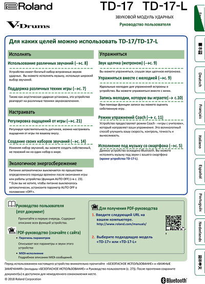
Это иллюстрированное руководство пользователя содержит в себе инструкции по всем режимам работы ударных Roland TD-17 и TD-17-L.
Содержание:
- Подготовка к работе
- Подключение к оборудованию
- Монтаж устройства на стойку
- Включение и выключение питания
- Калибровка хай-хэта
- Использование возможностей Bluetooth®
- О техниках звукоизвлечения
- Работа с устройством (описание панели)
- Запись
- Запись исполнения
- Запись на подключенный компьютер
- Упражнения
- Упражнения в режиме Coach
- Запись исполнения под музыку (разметочную дорожку)
- Редактирование набора
- Выбор пэда для редактирования.
- Выбор инструмента (ASSIGN)
- Регулировка громкости каждого пэда (LEVEL)
- Импорт и воспроизведение аудиофайлов (USER SAMPLE)
- Подстройка и глушение звука (TUNING/MUFFLING)
- Прочие настройки (OTHER)
- Копирование набора
- Резервирование и загрузка наборов
- Общие настройки (SETUP)
- Основные функции
- Редактирование настроек пэдов
- Резервирование на SD-карту
- Автоматическое выключение питания по прошествии времени (AUTO OFF)
- Восстановление заводских настроек
- Неисправности и способы устранения
- Безопасное использование
- Важные замечания
- Технические характеристики
Загрузка…
TD-17KVX
Check the included items
01
MDS-4KVX
* When checking the items
included with the MDS-
4KVX refer to «MDS-4KVX
Owner’s Manual. «
8 Kick pad (KD-10)
Assemble the stand
02
* The tip of the mount is sharp. Handle it with care.
* When setting up or storing the stand, be careful not to pinch the fingers you use to
handle the stand.
Assembly procedure
Assemble the stand using the procedure described in «MDS-4KVX Owner’s Manual. «
Loosen this hand knob, and rotate the
mount holder (L) 90 degrees in the direction
of the arrow.
Cymbal mounts
Pad mounts
Pad mounts
If the stand wobbles, loosen
this hand knob and adjust
the height.
* For reasons of safety, do not spread the stand
wider than 1.2 meters (47 inches).
Connect the pads to TD
04
Connection procedure
1.
2.
Connect the cable to TD as
Labels indicating the pad to
shown in the illustration.
be connected are attached
to the cable. Connect the
Insert the connector all the
cable to the OUTPUT jack of
way, then turn the knobs to
each pad as shown in the
fasten it securely.
illustration.
* Insert the plug firmly,
making sure it’s all the
way in.
Knob
Attaching the TD to a different location
You can change the location at which the TD is attached,
so that the hi-hat stand is on the outside as shown in the
illustration.
1.
Position the sound module mount as shown in the illustration below,
and attach it to the TD.
2.
Of the mount holders of curved pipe (L), insert the sound module
mount into the mount holder to which the cymbal mount is not
attached.
This completes assembly and connections.
Setup Guide
As soon as you open the package, check to see that all items are included. If anything is missing, please contact your dealer.
* This package does not include a kick pedal, and a hi-hat stand. Use with a commercially available kick pedal, hi-hat stand, and snare stand.
8 V-Cymbal for crash
8 V-Cymbal for ride
8 V-Hi-hat (VH-10)
(CY-12C x 2)
(CY-13R)
Attach the parts
03
Attach the hi-hat (VH-10)
Motion Sensor Unit
CONTROL OUT jack on the
farther side
Insulating Plate
Sponge side up
Cymbal mount
Compatible hi-hat stand
Diameter: 6.0–7.0 mm
(0.236″–0.276″)
Diameter: 11.7 mm (1/2″)
Max.
Adjusting the position of the cymbal
Adjust the height of the rod so that the highest point of the cymbal is
1.2 m
less than 1.2 meters.
BOW/EDGE
RD plug
OUTPUT jack
3.
Using the included trigger cable,
BELL
RDB plug
connect crash cymbal 2 to the
OUTPUT jack
TD’s CRASH 2 jack.
* Fasten the cables so that they will
Symbal side
not obstruct your playing; use cable
clips and cable ties.
Make sure to wrap the cable ties
around the pipes.
TD-17 side
For a left-handed setup
The setup described in this guide is for right-handed players. To set up for a left-handed player,
reattach the components as follows.
5 Exchange curved pipes (L) and (R), and straight pipes (L) and (R), left-for-right.
5 Attach holder (C) and the snare pipe to the right side.
5 Exchange the pads and cymbals with their attachment mounts left-for-right.
5 Exchange the TD with its sound module mount left-for-right.
Connect the cables as shown in the illustration.
As seen from the back
Using the included trigger cable, connect crash cymbal 2 to the TD’s
CRASH 2 jack.
In order to use this device correctly, please carefully read «Using
the Unit Safely» and «Important Notes» (included in each owner’s
manual) before use.
Parts of the TD-17KVX
8 V-Pad for snare (PDX-12)
8 V-Pad for tom
8 Drum sound module (TD)
(PDX-8 x 3)
(TD-17)
(Be sure to orient it correctly)
Attach the stopper so that
the bolt is on the right-hand
Clutch screw
side, from the performer’s
perspective.
Hi-Hat
«Roland» logo on the
farther side
Attach the TD
1.
Align the protrusions of the
sound module mount with the
rails of the TD, and slide it in until
you hear it click.
2.
Loosen the hand knob of the
mount holder, and insert the
sound module mount.
3.
Adjust the angle of the TD, and
then tighten the hand knob.
Attach the kick pedal (KD-10)
1.2 m
As seen from the back
Connection cable
Trigger cable
HH plug
RD
RDB
CR1
Crash
Cymbal 2
T2
T1
HHC plug
HH
HHC
T3
TD-17
SNR
KIK
RD RDB
CR1
HHC
HH
Crash
T1
T2
Cymbal 2
SNR
T3
TD-17
KIK
9
When you’ve finished making connections, turn on the power as described in the TD-17/17-L Owner’s Manual, and
verify that you can hear sound.
8 Connection cable
8 Trigger cable
8 AC adaptor
(special for TD)
Attach the crash cymbal (CY-12C) and ride cymbal (CY-13R)
Tighten the bolt with a drum key.
Tighten the wing nut to
Stopper
obtain an appropriate
amount of sway.
CY-12C
PDX-8
PDX-8
VH-10
TD-17
PDX-12
KD-10
Attach the snare (PDX-12) and toms (PDX-8)
Tighten
Loosen
Install the kick pedal securely.
Rod
Attach the cymbal so that its center does not extend toward the back
beyond the pipes of the stand (the pipes at the back of the stand).
Connect the AC adaptor
05
and speakers
TRIGGER OUT
Jack
Connect the AC adaptor, speakers, or headphones as described in the
owner’s manual of the TD.
CONTROL OUT
Jack
* To prevent malfunction and equipment failure, always turn down the volume, and turn
off all the units before making any connections.
(RD) (RDB)
CY-13R
CY-12C
(T3)
PDX-8
Connection cable
Curved pipe R
Trigger cable
(including the pad mount)
Straight pipe R
(short)
After exchanging the curved pipes, attach
Mark
the holders so that the marks on the pipes
Remove the caps, remove holder (C) and the snare pipe,
are visible through the gaps of the holders.
and reattach them to the right side.
© 2018 Roland Corporation
8 Setup Guide (this document)
8 Owner’s manual set
«Roland» logo on the farther side
Wing nut
Felt washer
CY-13R
CY-12C
PDX-8
Adjust the location at which
the KD-10 is installed so that
it’s at a comfortable position
for playing.
Tighten
Loosen
Rod
OK
Not OK
(CR1)
CY-12C
(T2)
(T1)
PDX-8
PDX-8
(HH)
VH-10
TD-17
(SNR)
PDX-12
(KIK)
KD-10
Curved pipe L
Straight pipe L (long)

Before using this unit, carefully read “USING THE UNIT SAFELY” and “IMPORTANT NOTES” (the leaet “USING THE UNIT SAFELY” and
the Owner’s Manual (p. 27)). After reading, keep the document(s) where it will be available for immediate reference.
© 2018 Roland Corporation
Owner’s Manual
Look What You Can Do with the TD-17/TD-17-L
Performing
Perform with various sounds (
&
p. 
A diverse selection of drum sounds is built into this unit.
You can perform using a wide variety of tonal choices.
Supports a variety of performance techniques
(
&
p. 7)
Just like acoustic drums, this unit responds to a variety of
dierent performance techniques.
Customizing
Adjust the playing feel (
&
p. 21)
By adjusting the sensitivity of the sensors, you can
customize the playing feel to your taste.
Create your very own kits (
&
p. 14)
By customizing a kit, you can create an original that’s like
no other kit in the world.
Eco-Friendly Power-Save Function
The power automatically turns o when a certain length
of time elapses after you stopped playing or operating the
unit (AUTO OFF function). (
&
p. 23)
* If you don’t want the power to turn o automatically, set
AUTO OFF to “OFF.”
Practicing
Sounding a click (metronome) (
&
p. 9)
You can practice while listening to a click sound.
Practicing along with a song (
&
p. 9)
Songs that are ideal for practice are built into this unit. You
can practice along with these songs.
Recording a song that you’re practicing (
&
p. 10)
You can use the recording function to evaluate your own
performance.
Practicing with Coach mode (
&
p. 11)
This unit provides a “Coach mode” that supports your
practicing. This is a great way to improve your speed
control, precision, and endurance.
Perform along with audio from your smartphone
(
&
p. 5)
This unit is equipped with Bluetooth. You can perform
along with audio from your smartphone (TD-17-L
excepted).
Owner’s Manual (this document)
Read this rst. This explains all the functions of
this unit.
PDF Manual (download from the web)
5 Data List
This explains the parameters and sound of
this unit.
5 MIDI Implementation
This is detailed reference material regarding
MIDI messages.
To obtain the PDF manual
1. Enter the following URL in your
computer.
http://www.roland.com/manuals/
I
2. Choose “TD-17” or “TD-17-L” as the product
name.


