![]()
Вибрационный сигнализатор уровня Rosemount 2120
Инструкция по эксплуатации
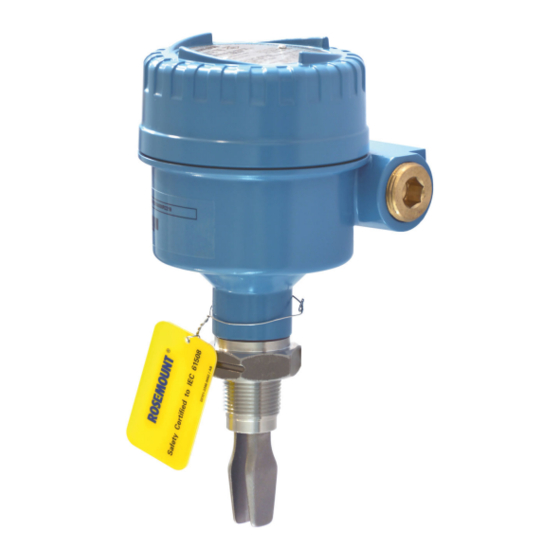
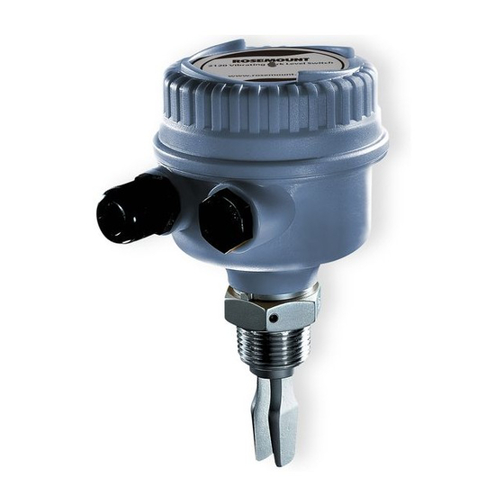
Датчик уровня RosemountTM 2120
Вибрирующая вилка
Руководство по технике безопасности 00809-0500-4030, ред. AJ
Март 2022
Сообщения о безопасности
ВНИМАНИЕ
Прочтите данное руководство перед началом работы с изделием. В целях личной безопасности и безопасности системы, а также для оптимальной работы продукта убедитесь, что вы полностью понимаете его содержимое перед установкой, использованием или обслуживанием этого продукта. Для получения технической помощи контакты указаны ниже:
центр обслуживания клиентов
Техническая поддержка, расценки и вопросы, связанные с заказом.
- США – 1-800-999-9307 (с 7:00 до 7:00 по центральному поясному времени)
- Азиатско-Тихоокеанский регион — 65 777 8211
Североамериканский центр реагирования
Требования к обслуживанию оборудования.
- 1-800-654-7768 (круглосуточно, включая Канаду)
- За пределами этих областей обращайтесь к местному представителю Emerson.
![]() ПРЕДУПРЕЖДЕНИЕ
ПРЕДУПРЕЖДЕНИЕ
Несоблюдение правил безопасной установки и обслуживания может привести к смерти или серьезной травме.
Убедитесь, что реле уровня установлено квалифицированным персоналом и в соответствии с применимыми нормами и правилами. Используйте реле уровня только так, как указано в данном руководстве. Невыполнение этого требования может привести к нарушению защиты, обеспечиваемой датчиком уровня. Вес сигнализатора уровня с тяжелым фланцем и удлиненной вилкой может превышать 37 фунтов (18 кг). Перед переноской, подъемом и установкой реле уровня требуется оценка риска.![]() ПРЕДУПРЕЖДЕНИЕ
ПРЕДУПРЕЖДЕНИЕ
Взрыв может привести к смерти или серьезным травмам.
Убедитесь, что рабочая атмосфера реле уровня соответствует требованиям соответствующих сертификатов для опасных зон. Перед подключением портативного коммуникатора во взрывоопасной среде убедитесь, что приборы установлены в соответствии с правилами искробезопасной или невоспламеняющейся полевой проводки. Во взрывозащищенных/пожаробезопасных и невоспламеняющихся установках не снимайте крышку корпуса при подаче питания на реле уровня. Крышка корпуса должна быть полностью закрыта, чтобы соответствовать требованиям пожаробезопасности/взрывозащиты.![]() ПРЕДУПРЕЖДЕНИЕ
ПРЕДУПРЕЖДЕНИЕ
Поражение электрическим током может привести к смерти или серьезным травмам.
Избегайте контакта с проводами и клеммами. Высокий объемtagд., которые могут присутствовать на проводах, могут привести к поражению электрическим током. Убедитесь, что питание реле уровня отключено, а линии к любому другому внешнему источнику питания отключены или обесточены при подключении реле уровня. Убедитесь, что проводка подходит для электрического тока, а изоляция подходит для напряжения.tagе, температура и окружающая среда.![]() ПРЕДУПРЕЖДЕНИЕ
ПРЕДУПРЕЖДЕНИЕ
Утечки в процессе могут привести к смерти или серьезным травмам.
Обеспечьте осторожное обращение с переключателем уровня. Если технологическое уплотнение повреждено, газ может выйти из сосуда (резервуара) или трубы.![]() ПРЕДУПРЕЖДЕНИЕ
ПРЕДУПРЕЖДЕНИЕ
Физический доступ Неуполномоченный персонал потенциально может причинить значительный ущерб и/или неверную настройку оборудования конечных пользователей.
Это может быть преднамеренным или непреднамеренным и должно быть защищено от. Физическая безопасность является важной частью любой программы безопасности и имеет основополагающее значение для защиты вашей системы. Ограничьте физический доступ неавторизованного персонала для защиты активов конечных пользователей. Это относится ко всем системам, используемым на объекте.![]() ВНИМАНИЕ!
ВНИМАНИЕ!
Продукты, описанные в этом документе, НЕ предназначены для применения в ядерной области.
Использование неядерных сертифицированных продуктов в приложениях, требующих оборудования или продуктов, сертифицированных для ядерной энергетики, может привести к неточным показаниям. Для получения информации о продуктах Rosemount, предназначенных для использования в атомной энергетике, обратитесь к местному торговому представителю Emerson.![]() ВНИМАНИЕ!
ВНИМАНИЕ!
Горячие поверхности Фланец и технологическое уплотнение могут быть горячими при высоких температурах технологического процесса. Дайте остыть перед обслуживанием.
Прежде чем вы начнете
1.1 Об этом документе
В этом документе содержится информация об установке, вводе в эксплуатацию и контрольных испытаниях реле уровня Rosemount 2120 в соответствии с требованиями к автоматизированным системам безопасности (SIS).
Внимание Должны применяться следующие условия:
- Реле уровня установлено правильно и полностью в соответствии с инструкциями Справочного руководства и Краткого руководства.
- Установка соответствует всем применимым требованиям безопасности.
- Оператор обучен местным и корпоративным стандартам безопасности.
1.2 Об этом продукте
Сигнализатор уровня Rosemount 2120 состоит из камертона с элементом возбуждения и приемника, а также встроенной электроники интерфейса. Детектор уровня основан на принципе изменения резонансной частоты камертона при погружении его в жидкость. Изменение частоты обнаруживается и используется для переключения электрического выхода. Доступен ряд вариантов вывода для различных приложений.
1.2.1 Приложение exampле
Реле уровня показывает с помощью электронного выхода, находится ли уровень технологической жидкости выше или ниже определенной точки (точки переключения).
Рисунок 1-1: Примерample Защита от переполнения приложения
1.3 Связанные документы
Вы можете найти всю документацию по продукту на Emerson.com/Rosemount.
Для получения дополнительной информации см. Следующие документы:
Таблица 1-1: Сопутствующая документация
Установка и ввод в эксплуатацию
2.1 Сертификация автоматизированной системы безопасности (SIS)
При использовании автоматизированных систем безопасности электрическая выходная мощность используется в качестве основной переменной безопасности. Он настроен на активацию функции будильника в случае возникновения ошибки. Rosemount 2120 может использоваться в приложениях высокого уровня, связанных с безопасностью. Сигнал измерения, используемый логическим вычислителем, должен представлять собой дискретные уровни, установленные на выходе прибора, используемые для индикации состояния датчика. Изменение уровня жидкости через точку переключения реле уровня приводит к тому, что на выходе прибора устанавливается настроенное пользователем состояние. Для моделей с кодами H, K и G только для Dry=On Rosemount 2120 сертифицирован по стандарту IEC 61508 на:
- Низкий спрос: элемент типа B
- SIL 2 для произвольной целостности при HFT=0
- SIL 3 для произвольной целостности при HFT=1
- SIL 3 для систематической работы. Для модели с кодом V, только для Dry=On, Rosemount 2120 сертифицирован по IEC 61508 на:
- Низкий спрос: элемент типа B
- SIL 1 для произвольной целостности при HFT=0
- SIL 2 для произвольной целостности при HFT=1
- SIL 3 для систематической способности
2.2 Идентификация, сертифицированная по безопасности
Перед установкой в системы СПАЗ все сигнализаторы уровня Rosemount 2120 должны быть идентифицированы как сертифицированные по безопасности. В Таблице 2-1 перечислены версии сигнализаторов уровня Rosemount 2120, которые рассматривались для оценки аппаратного обеспечения, к которым относится этот раздел.
- Модели с кодом опции QT сертифицированы аккредитованным сторонним агентством по стандарту IEC 61508 для использования в системах безопасности до SIL 3. (для однократного использования (3oo1) с уровнем SIL 1 и для резервного использования (2oo1 или 2oo2), до SIL 3.)
- Модели с кодом опции QS поставляются с сертификатом предыдущего использования производителя с данными FMEDA.
Табл. 2-1. Коды моделей сертифицированных по безопасности опций Rosemount серии 2120
| Датчик уровня Rosemount 2120 | |
| аппаратные средства | Модель 2120 Z ZZ GZ ZZ Z ZZZZ QT. Сухой=Вкл. Модель 2120 Z ZZ KZ ZZ Z ZZZZ QT. Сухой=Вкл. Модель 2120 Z ZZ HZ ZZ Z ZZZZ QT. Сухой=Вкл. Модель 2120 Z ZZ VZ ZZ Z ZZZZ QT. Сухой=Вкл. |
| Внимание Переключатели будут помечены «QS» или «QT» в конце номера модели. |
|
| Z – разные варианты, см. Технический паспорт. Г – ПНП/ПЛК К – НАМЮР H- 8/16 мА В — Реле |
|
| Программное обеспечение / Прошивка | G:1.0.0 или выше H:2.10.0 или выше K: 2.10.0 или выше V: 2.10.0 или выше |
2.2.1 Идентификация выключателя, сертифицированного по безопасности
Чтобы идентифицировать датчик уровня Rosemount 2120, сертифицированный по безопасности:
Процедура
- Убедитесь, что к коду модели добавлен код опции QT или QS.
- Подтвердите желтый tag прикрепляется снаружи реле уровня для кода опции QT.
Установка 2.3
Датчик уровня Rosemount 2120 должен быть установлен, как описано в разделе по установке изделия. Датчик уровня Rosemount 2120 (emerson.com).
Условия окружающей среды не должны превышать значений, указанных в разделе технических характеристик Датчик уровня Rosemount 2120 (emerson.com). Реле уровня должно быть доступно для физического осмотра.
2.4 Конфигурация
2.4.1 Настройка режима вывода
Реле уровня Rosemount 2120 должно быть настроено пользователем для применения таким образом, чтобы выход был включен в безопасном или нормальном состоянии.
Время отклика (задержка в секундах) может быть установлено на удобное значение для предотвращения ложных отключений, т.е. не связанных с реальным состоянием. Обратите внимание, что время реакции безопасности превышает 10 секунд, а задержка выбрана в секундах с помощью настройки переключателя.
Таблица 2-2: Настройка режима вывода
3.1 Контрольные испытания
3.1.1 Болееview
Rosemount 2120 необходимо регулярно проверять для выявления неисправностей, которые не обнаруживаются автоматической диагностикой. Пользователь несет ответственность за выбор типа тестирования и частоты этих тестов.
Результаты периодических контрольных испытаний должны регистрироваться и периодически пересматриваться.viewизд. Если обнаружена ошибка в функции безопасности, устройство должно быть выведено из эксплуатации, а процесс должен поддерживаться в безопасном состоянии с помощью других мер.
Внимание Для получения достоверного результата всегда выполняйте контрольную проверку продукта, который будет храниться в резервуаре во время работы устройства.
3.1.1 Предлагаемые контрольные испытания
Предлагаются следующие проверочные тесты:
- (A) Комплексное контрольное испытание
- (B) Частичное контрольное испытание
Таблицу 3-1 можно использовать в качестве руководства для выбора подходящего контрольного испытания.
Таблица 3-1: Предлагаемые контрольные испытания
| Контрольный тест # | Тип выхода и код модели | Покрытие контрольным тестом (%) DU | Оставшиеся опасные, необнаруженные сбои | Тестирование | Может быть выполнены удаленно |
|||
| Схема выхода | Анализ эффективности электроника |
датчик | ||||||
| A | 8/16 мА | H | 89 | 3 FIT | Да | Да | Да | Нет |
| NAMUR | K | 88 | 3 FIT | |||||
| ПНП/ПЛК | G | 74 | 11 FIT | |||||
| Реле | V | 75 | 26 FIT | |||||
| B | 8/16 мА | H | 81 | 6 FIT | Да | Да | Да | Нет |
| NAMUR | K | 76 | 6 FIT | |||||
| ПНП/ПЛК | G | 68 | 13 FIT | |||||
| Реле | V | 69 | 32 FIT |
Связанная информация
Комплексное контрольное тестирование
Частичное контрольное тестирование
3.1.2 Интервал контрольных испытаний
Временные интервалы для контрольных испытаний определяются проверочным расчетом SIL (в соответствии с PFDAVG). Расчет проверки SIL — это аналитический метод для расчета соответствующего интервала контрольных испытаний для конкретной функции безопасности на основе надежности оборудования и требуемого снижения риска для конкретной SIF.
Проверочные испытания должны выполняться чаще или так часто, как указано в расчете проверки SIL, чтобы поддерживать требуемую полноту безопасности всей SIF.
3.1.3 Необходимые инструменты
- Voltage или амперметр, в зависимости от типа выхода
- Источник питания
- Решатель логики безопасности
3.2 Комплексное контрольное тестирование
Комплексное контрольное испытание выполняет полную проверку элементов системы. Датчик, измерительная электроника и выходныеtage все проверяются изменением состояния датчика и наблюдением за выходным сигналом.
В соответствии со стандартом IEC 61508-2 должны быть проведены контрольные испытания для выявления опасных отказов, которые не обнаруживаются при диагностических испытаниях. Это означает, что необходимо указать, насколько опасные необнаруженные отказы, которые были отмечены в ходе анализа видов отказов, последствий и диагностического анализа, могут быть обнаружены во время контрольных испытаний.
Внимание Rosemount 2120 с электроникой 8 и 16 мА, NAMUR или PNP/PLC, а также работающий в режиме Dry=On, предназначен для приложений высокого уровня SIL2.
Rosemount 2120 с релейной электроникой, также установленный в режим Dry=On, предназначен для приложений высокого уровня SIL1.
Связанная информация
Предлагаемые контрольные тесты
3.2.1 Влияние на SIF и процесс
Для достижения безопасного состояния продукта датчик должен быть либо извлечен из технологической среды, либо погружен в нее, в зависимости от режима работы. Нельзя допустить, чтобы процесс работал во время проведения проверочного испытания.
3.2.2 Выполнение комплексного контрольного испытания
Процедура
- Осмотрите доступные части датчика уровня на наличие утечек или повреждений.
- Обойдите функцию безопасности и примите соответствующие меры, чтобы избежать ложного срабатывания.
- Убедитесь, что переключатель режимов установлен в требуемый режим работы.
- Отключите любой дренажный механизм и заполните сосуд, чтобы принудительно перевести переключатель в отказобезопасное состояние, и убедитесь, что безопасное состояние было достигнуто в течение времени, указанного в настройке переключателя режима.
 ВНИМАНИЕ!
Необходимо принять независимые меры предосторожности, чтобы гарантировать, что эта операция не приведет к возникновению какой-либо опасности. - Восстановите механизм слива, чтобы сосуд снова наполнился, и убедитесь, что нормальное рабочее состояние переключателя достигнуто.
- Удалите обход функции безопасности и восстановите нормальную работу другим способом.
3.2.3 Продолжительность комплексного контрольного испытания
Всеобъемлющая контрольная проверка занимает несколько часов с соблюдением всех мер безопасности.
3.3 Частичное контрольное тестирование
Реле уровня может выполнять частичное контрольное испытание. Этот тест имеет меньший диагностический охват по сравнению с комплексным контрольным тестом, поскольку он ограничивается проверкой только выходной и измерительной электроники.
Частичное контрольное испытание имеет следующие преимущества:
- Обеспечивает процентtage всестороннего охвата проверочными испытаниями, что позволяет протестировать устройство и уменьшить его эффективную PFD на этот процент.tagе во время теста.
- Тест может быть выполнен «в процессе» и занимает менее одной минуты.
- Обеспечивает возможность продления всесторонних испытаний в соответствии со стандартными графиками технического обслуживания предприятия.
- Может дать пользователю возможность запланировать интервал комплексного проверочного тестирования в соответствии с запланированным планом сайта.
Предлагаемое частичное контрольное испытание для сигнализатора уровня RosemountTM 2120 проверяет обработку и вывод сигнала, но не проверяет датчик.
Внимание Rosemount 2120 с электроникой 8 и 16 мА, NAMUR или PNP/PLC, а также работающий в режиме Dry=On, предназначен для приложений высокого уровня SIL2.
Rosemount 2120 с релейной электроникой, также установленный в режим Dry=On, предназначен для приложений высокого уровня SIL1.
Связанная информация
Предлагаемые контрольные тесты
3.3.1 Влияние на SIF и процесс
Нельзя допустить, чтобы процесс работал, пока выполняется проверочное испытание.
3.3.2 Выполнение частичного контрольного испытания
Процедура
- Осмотрите доступные части датчика уровня на наличие утечек или повреждений.
- Обойдите функцию безопасности и примите соответствующие меры, чтобы избежать ложного срабатывания.
- Убедитесь, что переключатель режимов установлен в требуемый режим работы.
- Приложите стержневой магнит к магнитной контрольной точке, чтобы перевести переключатель в безопасное состояние, и убедитесь, что безопасное состояние было достигнуто в течение 2 с. ВНИМАНИЕ!
Необходимо принять независимые меры предосторожности, чтобы гарантировать, что эта операция не приведет к возникновению какой-либо опасности. - Восстановите механизм слива, чтобы сосуд снова наполнился, и убедитесь, что нормальное рабочее состояние переключателя достигнуто.
- Удалите обход функции безопасности и восстановите нормальную работу другим способом.
3.3.3 Продолжительность частичного контрольного испытания
Частичное контрольное испытание занимает менее часа с соблюдением всех мер безопасности.
Эксплуатационные ограничения
4.1 Технические характеристики
Rosemount 2120 должен эксплуатироваться в соответствии с функциональными и эксплуатационными характеристиками, указанными в техническом описании Rosemount 2120.
4.1.1 Данные о частоте отказов
Отчет FMEDA включает данные о частоте отказов, детали оценки и предположения относительно анализа частоты отказов.
4.1.2 Время отклика преобразователя
Время срабатывания безопасности для всех типов выходов превышает 10 секунд или выбранную задержку в секундах с помощью настройки переключателя.
Таблица 4-1: Время отклика преобразователя
| Тип выхода и код модели | Объем поставкиtage | Уровни аварийной сигнализации (токи утечки)(1) |
Время отклика передатчика(2) | Точка переключения (вода)(3) | Точка переключения (другое жидкость)(4) |
|
| 8 и 16 мА | 1< | 11 в 36 Vdc | <8.5 мА | минимум 10 с | 11 к 15 мм | 0 к 30 мм |
| NAMUR | H | 7 в 9 Vdc | 1.0 мА | |||
| ПНП/ПЛК | G | 20 в 60 Vdc | < 100 }ИА | |||
| Реле | V | от 20 до 60 В постоянного тока от 20 до 264 В постоянного тока | Нет |
- Уровни отключения логического решающего устройства должны быть установлены выше этих значений, чтобы обеспечить надежные отключения.
- Время срабатывания безопасности больше 10 секунд или заданной задержки в секундах с использованием настройки переключателя.
- Рабочая (переключающая) точка измеряется от самой нижней точки вилки, когда жидкостью является вода.
- Рабочая точка (переключение) измеряется от самой нижней точки вилки, когда жидкость не является водой.
4.1.3 Интервал диагностических испытаний
Все диагностические проверки были полностью завершены в течение одного часа (< 60 мин).
4.1.4 Срок службы
Основываясь на общих данных об отказах в полевых условиях и данных производителей компонентов, ожидается, что срок службы реле уровня Rosemount 10 при температуре окружающей среды 2120 °C составит около 55 лет.
Ожидаемый срок службы варианта H (8/16 мА) составляет около 20 лет.
Это уменьшается в два раза при каждом повышении температуры на 10 °C и увеличивается в два раза при каждом снижении температуры на 10 °C.
4.2 Ремонт изделия
Процедуры ремонта сигнализатора уровня Rosemount 2120 Датчик уровня Rosemount 2120 (emerson.com) должно быть выполнено
В случае неисправности системы или SIF датчик уровня Rosemount 2120 должен быть выведен из эксплуатации, а процесс должен поддерживаться в безопасном состоянии с помощью других мер.
Компания Emerson должна быть проинформирована о необходимости замены Rosemount 2120 из-за неисправности. Произошедшая неисправность должна быть задокументирована, и о ней необходимо сообщить в Emerson, используя контактную информацию, указанную на последней странице настоящего руководства по функциональной безопасности. Это важная часть процесса управления Emerson SIS.
Rosemount 2120 подлежит ремонту путем замены основных компонентов. Необходимо сообщать обо всех отказах, обнаруженных диагностикой устройства или контрольным испытанием. Отзыв можно отправить в электронном виде по адресу Go.EmersonAutomation.com/Контакты (Свяжитесь с нами).
Термины и определения
| λDU | Опасная частота необнаруженных отказов |
| λDU | Частота опасных обнаруженных отказов |
| λDU | Безопасный необнаруженный уровень отказов |
| λDU | Интенсивность обнаруженных безопасных отказов |
| Интервал диагностики | Время от момента возникновения опасного сбоя/состояния до момента, когда устройство установит выход, связанный с безопасностью, в безопасное состояние (общее время, необходимое для обнаружения сбоя и реакции на сбой). |
| Элемент | Термин, определенный стандартом IEC 61508 как «часть подсистемы, состоящей из одного компонента или любой группы компонентов, которая выполняет одну или несколько функций безопасности элемента». |
| FIT | Отказ во времени на миллиард часов |
| ФМЕДА | Виды отказов, последствия и диагностический анализ |
| Протокол HART® | Удаленный датчик с адресацией для шоссе |
| HFT | Аппаратная отказоустойчивость |
| Режим высокого спроса | Функция безопасности выполняется только по запросу, чтобы перевести EUC (управляемое оборудование) в заданное безопасное состояние, и когда частота запросов превышает один раз в год (IEC 61508-4). |
| Режим низкого спроса | Функция безопасности выполняется только по запросу, чтобы перевести EUC в заданное безопасное состояние, и когда частота запросов не превышает одного раза в год (IEC 61508-4). |
| ПФДАВГ | Средняя вероятность отказа по запросу |
| ПФХ | Вероятность опасного отказа в час: термин «вероятность» вводит в заблуждение, поскольку IEC 61508 определяет скорость. |
| Фактор покрытия контрольным тестом | Эффективность проверочного тестирования описывается коэффициентом охвата, определяющим долю обнаруженных опасных необнаруженных отказов (λDU). Коэффициент охвата является показателем эффективности проверочного теста для обнаружения опасных невыявленных сбоев. |
| Отклонение от безопасности | Максимально допустимое отклонение предохранительного выхода из-за неисправности внутри устройства (выражается в процентах).tagе пролета). Любой сбой, приводящий к тому, что выходной сигнал устройства заряжается меньше, чем безопасное отклонение, считается сбоем «без последствий». Все сбои, вызывающие изменение выходного сигнала устройства больше, чем безопасное отклонение, при этом выходной сигнал устройства все еще находится в пределах активного диапазона (неаварийное состояние), считаются опасными сбоями. Внимание Безопасное отклонение не зависит от нормальных рабочих характеристик или какой-либо дополнительной погрешности измерения, связанной с конкретным приложением. |
| SIF | Инструментальная функция безопасности |
| SIL | Уровень полноты безопасности – дискретный уровень (один из четырех) для определения требований к полноте безопасности функций безопасности ПСБ, которые должны быть отнесены к ПСБ. SIL 4 имеет самый высокий уровень полноты безопасности, а SIL 1 — самый низкий уровень. |
| SIS | Инструментальная система безопасности – инструментальная система, используемая для реализации одной или нескольких функций безопасности. SIS состоит из любой комбинации датчиков, логических решателей и исполнительных элементов. |
| Систематическая способность | Мера (выраженная по шкале от SC 1 до SC 4) уверенности в том, что систематическая полнота безопасности элемента соответствует требованиям заданного SIL в отношении заданной функции безопасности элемента, когда элемент применяется в соответствии с инструкции, указанные в руководстве по безопасности соответствующего элемента для элемента. |
| Время отклика передатчика | Время от ступенчатого изменения процесса до достижения выходным сигналом преобразователя 90 % его конечного установившегося значения (время отклика на скачок согласно IEC 61298-2). |
| Устройство типа В | Сложное устройство, использующее контроллеры или программируемую логику, как определено стандартом IEC 61508. |
| Срок полезного использования | Термин техники надежности, который описывает рабочий интервал времени, когда частота отказов устройства относительно постоянна. Это не термин, который охватывает устаревание продукта, гарантию или другие коммерческие вопросы. Срок службы сильно зависит от самого элемента и условий его эксплуатации (IEC 61508-2). |
Для получения дополнительной информации: Emerson.com
© 2022 Emerson. Все права защищены.
Условия продажи Emerson доступны по запросу. Логотип Emerson является товарным знаком и знаком обслуживания Emerson Electric Co.
Rosemount является торговой маркой одной из компаний семейства Emerson. Все остальные товарные знаки являются собственностью их соответствующих владельцев.
РОЗЕМУНТ™![]()
Документы / Ресурсы
Рекомендации
-
Contents
-
Table of Contents
-
Troubleshooting
-
Bookmarks
Quick Links
Reference Manual
00809-0100-4030, Rev GA
March 2022
™
Rosemount
2120 Level Switch
Vibrating Fork
Related Manuals for Emerson Rosemount 2120
Summary of Contents for Emerson Rosemount 2120
-
Page 1
Reference Manual 00809-0100-4030, Rev GA March 2022 ™ Rosemount 2120 Level Switch Vibrating Fork… -
Page 2
• 1-800-654-7768 (24 hours a day — includes Canada) • Outside of these areas, contact your local Emerson representative. WARNING Failure to follow safe installation and servicing guidelines could result in death or serious injury. Ensure the level switch is installed by qualified personnel and in accordance with applicable code of practice. -
Page 3
Equipment ratings and certifications are no longer valid on any products that have been damaged or modified without the prior written permission of Emerson. Any continued use of product that has been damaged or modified without the written authorization is at the customer’s sole risk and expense. -
Page 5: Table Of Contents
6.6 Spare parts……………………..60 6.7 Replacement and calibration of cassettes……………… 61 6.8 Opening the lid (cover)………………….63 6.9 Service support……………………..63 Appendix A Specifications and reference data…………….65 A.1 General……………………….65 A.2 Physical specifications………………….. 65 A.3 Performance specifications………………….67 A.4 Electrical specifications………………….67 Rosemount 2120 Level Switch…
-
Page 6
Contents Reference Manual March 2022 00809-0100-4030 A.5 Functional specifications………………….68 A.6 Environmental specifications…………………68 A.7 Dimensional drawings………………….. 71 Reference Manual… -
Page 7: Chapter 1 Introduction
Introduction Using this manual The sections in this manual provide detailed information on installing, operating, and maintaining the Rosemount 2120 Level Switch — Vibrating Fork. The sections are organized as follows: Level switch overview provides a description of the level switch and its basic principles.
-
Page 8
Introduction Reference Manual March 2022 00809-0100-4030 Reference Manual… -
Page 9: Level Switch Overview
Process characteristics Emerson’s vibrating fork technology is virtually unaffected by turbulence, foam, solids content, coating products, and liquid properties. The natural frequency (1400 Hz) of the fork avoids interference from plant vibration that may cause false switching to a wet state.
-
Page 10: Application Examples
Spillage caused by overfilling can be hazardous to people and the environment, resulting in lost product and potentially high clean-up costs. The Rosemount 2120 is an overfill prevention product from Emerson that can be used as one of multiple layers of protection.
-
Page 11
By selecting the option of direct load switching or relay electronics, the Rosemount 2120 is ideal for reliable pump control and can be used to protect against pumps running dry. -
Page 12: Components Of The Level Switch
2.5.2 Fork design The “fast drip” design allows the liquid to be quickly drawn away from the fork tip, making the Rosemount 2120 quicker and more responsive in high density or viscous liquid applications. Reference Manual…
-
Page 13
Magnetic test point A magnetic test point is located on the side of the housing, allowing a functional test of the Rosemount 2120 and a system connected to it. Holding a magnet to the test point causes the output to change state. -
Page 14
Level switch overview Reference Manual March 2022 00809-0100-4030 Reference Manual… -
Page 15: Chapter 3 Mechanical Installation
In explosion-proof/flameproof and non-incendive installations, do not remove the housing cover when power is applied to the level switch. The housing cover must be fully engaged to meet flameproof/explosion-proof requirements. Rosemount 2120 Level Switch…
-
Page 16: Installation Considerations
Before installing the level switch, review the safety, environmental, application, and pre- installation sections. 3.2.1 Environmental considerations The Rosemount 2120 is weatherproof and protected against the ingress of dust, but must be protected from flooding. Avoid installing the level switch near heat sources. Reference Manual…
-
Page 17
Figure 3-1: Environmental Considerations 3.2.2 Application considerations The Rosemount 2120 is a wired point-level device for use on open or closed vessels (tanks) and in pipework containing liquid mediums. For most liquids, including coating, aerated liquids and slurries, the function is virtually unaffected by flow, turbulence, bubbles, foam, vibration, solid particles, build-up, or properties of the liquid medium. -
Page 18
Emerson. Foams In almost all cases, the Rosemount 2120 is insensitive to foams (i.e. does not see the foam). However in rare occasions, some very dense foams may be seen as liquid; known examples of this are found in ice-cream and orange juice manufacturing. -
Page 19
Figure 3-3: Switching Point in Inches (Millimeters) (2.5) (13) (13) Note When mounted vertically, a low density medium has a switching point closer to the process connection. A high density medium has a switching point closer to fork tip. Rosemount 2120 Level Switch… -
Page 20
Mechanical installation Reference Manual March 2022 00809-0100-4030 3.2.3 Pre-installation considerations Measurement accuracy is dependent upon the proper installation of the device. Keep in mind the need for easy access, personnel safety, practical field calibration, and a suitable environment for the device. Device identification To identify a version of the level switch, see the labels on the housing and on the electronics cassette inside the housing. -
Page 21
On metal housing versions, metal must contact metal to form a good seal. Always use Emerson’s O-rings. Mounting orientation Mount the Rosemount 2120 at any angle that allows the level of the process medium to rise, fall, or flow through the fork gap. Related information… -
Page 22
Mechanical installation Reference Manual March 2022 00809-0100-4030 Insulation Figure 3-6: Insulation A. 3.9 in. (100 mm) clearance all around ® B. ROCKWOOL Pipe installation requirements • The inside pipe diameter (D) must be 1.4 in. (35 mm) or larger. • Ensure the fork tines intrude at least 0.9 in. -
Page 23
Extra consideration is needed if the plant vibration is close to the 1400 Hz operating frequency of the fork. Required supports for extended fork Supporting the extended fork avoids long fork length vibration. Figure 3-8: Vertical Installation (Standard) A. Maximum 3.28 ft. (1.0 m) B. 3.28 ft. (1.0 m) Rosemount 2120 Level Switch… -
Page 24
Mechanical installation Reference Manual March 2022 00809-0100-4030 Figure 3-9: Vertical Installation (Marine GL Approved) A. Maximum 1.3 ft. (0.4 m) B. 2.3 ft. (0.7 m) C. 0.65 ft. (0.2 m) Figure 3-10: Horizontal Installation (Standard) A. Maximum 3.28 ft. (1.0 m) B. -
Page 25
Reference Manual Mechanical installation 00809-0100-4030 March 2022 Figure 3-11: Horizontal Installation (Marine GL Approved) A. Maximum 1.3 ft. (0.4 m) B. 2.3 ft. (0.7 m) C. 0.65 ft. (0.2 m) Rosemount 2120 Level Switch… -
Page 26: Installation Procedures
Mechanical installation Reference Manual March 2022 00809-0100-4030 Installation procedures 3.3.1 Process connection seals Figure 3-12: Process Connection Seals A. PTFE tape B. NPT or BSPT (R) thread C. Gasket D. BSPP (G) thread E. Tri Clamp F. The Tri Clamp seal is supplied in an accessory kit Reference Manual…
-
Page 27
The fork is correctly aligned by positioning the groove or notch as indicated (Figure 3-14). Figure 3-14: Correct Fork Alignment for Vessel (Tank) Installation A. Tri Clamp process connections have a circular notch B. Threaded process connections have a groove C. Flanged process connections have a circular notch Rosemount 2120 Level Switch… -
Page 28
Mechanical installation Reference Manual March 2022 00809-0100-4030 3.3.3 Mounting the threaded version Threaded vessel (tank) or pipework connection Procedure 1. Seal and protect the threads. Use anti-seize paste or PTFE tape according to site procedures. A gasket may be used as a sealant for BSPP (G) threaded connections. 2. -
Page 29
2. Tighten the bolts and nuts with sufficient torque for the flange and gasket. 3. Seal and protect the threads. Use anti-seize paste or PTFE tape according to site procedures. A gasket may be used as a sealant for BSPP (G) threaded connections. Rosemount 2120 Level Switch… -
Page 30
Mechanical installation Reference Manual March 2022 00809-0100-4030 4. Screw the level switch into the flange thread. Note Tighten using the hexagon nut only. A. Gasket for BSPP (G) threaded connection 3.3.4 Mounting the flanged version Procedure 1. Lower the level switch into the nozzle. A. -
Page 31
2. Tighten the bolts and nuts with sufficient torque for the flange and gasket. 3.3.5 Mounting the Tri Clamp version Procedure 1. Lower the level switch into the flange face. A. Seal (supplied with Tri Clamp) 2. Fit the Tri Clamp. Rosemount 2120 Level Switch… -
Page 32
Mechanical installation Reference Manual March 2022 00809-0100-4030 Reference Manual… -
Page 33: Chapter 4 Electrical Installation
In explosion-proof/flameproof and non-incendive installations, do not remove the housing cover when power is applied to the level switch. The housing cover must be fully engaged to meet flameproof/explosion-proof requirements. Rosemount 2120 Level Switch…
-
Page 34: Prepare The Electrical Connections
Electrical installation Reference Manual March 2022 00809-0100-4030 WARNING Electrical shock could cause death or serious injury. Avoid contact with the leads and terminals. High voltage that may be present on leads can cause electrical shock. Ensure the power to the level switch is off, and the lines to any other external power source are disconnected or not powered while wiring the level switch.
-
Page 35
Before use, check the cable glands and blanking plugs are suitably rated. • Isolate supply before connecting the switch or removing the electronics. • The Protective Earth (PE) terminal must be connected to an external earthing system. Note When replacing a cassette, it is important to re-calibrate. Rosemount 2120 Level Switch… -
Page 36
The Rosemount 2120 requires a minimum current to operate (I ), which continues to flow when the output is ‘off’. If selecting a relay to wire in series with the Rosemount 2120, ensure the drop-out voltage of the relay is greater than the voltage generated across the relay coil when I flows through it. -
Page 37
Mode: wet on, low level alarm < 4 mA < 4 mA 12 V 12 V DPST DPST DPST DPST LED on continuously LED flashes every second LED on continuously LED flashes every second = Load on = Load off Rosemount 2120 Level Switch… -
Page 38
Electrical installation Reference Manual March 2022 00809-0100-4030 PNP/PLC cassette Figure 4-2: PNP/PLC (3-wire) Cassette (Yellow Label) – Code G Wet On Mode O/P 0V F = Fuse 2A(T) Table 4-3: Electrical Parameters Parameter Value 20 — 60 Vdc < 4 mA + I <… -
Page 39
<100 μA <100 μA < 3 V < 3 V PNP dc < 3 V < 3 V <100 μA <100 μA LED on continuously LED flashes every second LED on continuously LED flashes every second Rosemount 2120 Level Switch… -
Page 40
Electrical installation Reference Manual March 2022 00809-0100-4030 Relay DPCO cassette (standard version) Figure 4-3: Relay DPCO Cassette, Standard Version (Green Label) – Code V Fuse 0.5 (T) DPST Note A DPST (Double Pole, Single Throw) on/off switch must be fitted for safe disconnection of the power supply. -
Page 41
NC C NO NC C NO NC C NO NC C NO NC C NO NC C NO NC C NO NC C NO LED on continuously LED flashes every second LED on continuously LED flashes every second Rosemount 2120 Level Switch… -
Page 42
A DPST (Double Pole, Single Throw) on/off switch must be fitted for safe disconnection of the power supply. Fit the DPST switch as near as possible to the Rosemount 2120. Keep the DPST switch free of obstructions. Label the DPST switch to indicate it is the supply disconnection device for the Rosemount 2120. -
Page 43
NC C NO NC C NO NC C NO NC C NO NC C NO NC C NO NC C NO NC C NO LED on continuously LED flashes every second LED on continuously LED flashes every second Rosemount 2120 Level Switch… -
Page 44
Figure 4-5: NAMUR Cassette (Light Blue Label) – Code K A. A certified intrinsically safe isolating amplifier to IEC 60947-5-6 Note • This cassette is suitable for Intrinsically Safe (IS) applications and requires a certified isolating barrier. See the Rosemount 2120 Product Certifications document for Intrinsically Safe approvals. •… -
Page 45
Mode: dry on, high level alarm Mode: wet on, low level alarm > 2.2 mA < 1.0 mA > 2.2 mA < 1.0 mA LED on continuously LED flashes every second LED on continuously LED flashes every second Rosemount 2120 Level Switch… -
Page 46
Figure 4-6: 8/16 mA Cassette (Dark Blue Label) – Code H A. A certified intrinsically safe isolating amplifier to IEC 60947-5-6 Note • This cassette is suitable for Intrinsically Safe (IS) applications and requires a certified isolating barrier. See the Rosemount 2120 Product Certifications document for Intrinsically Safe approvals. •… -
Page 47
Mode: dry on, high level alarm Mode: wet on, low level alarm > 15 mA < 8.5 mA > 15 mA < 8.5 mA LED on continuously LED flashes every second LED on continuously LED flashes every second Rosemount 2120 Level Switch… -
Page 48: Connect Wiring And Power Up
Electrical installation Reference Manual March 2022 00809-0100-4030 4.2.6 Grounding Make sure grounding is done according to national and local electrical codes. Failure to do so may impair the protection provided by the equipment. Signal cable shield grounding Make sure the instrument cable shield is: •…
-
Page 49
Versions of the Rosemount 2120 with a glass-filled-nylon housing are not explosion-proof/flameproof. They do not have a cover-lock. 3. Remove the plastic plugs. Versions of the Rosemount 2120 with a glass-filled-nylon housing do not have plastic plugs fitted. 4. Pull cables through the cable gland/conduits. -
Page 50
Electrical installation Reference Manual March 2022 00809-0100-4030 5. Connect the cable wires (see Wiring diagrams for other cassettes). Metal housing: Glass-filled-nylon housing: 6. Ensure proper grounding. Reference Manual… -
Page 51
Reference Manual Electrical installation 00809-0100-4030 March 2022 7. Tighten the cable glands. Apply PTFE tape or other sealant to the threads. Metal housing: Glass-filled-nylon housing: Note Make sure to arrange the wiring with a drip loop. Rosemount 2120 Level Switch… -
Page 52
Electrical installation Reference Manual March 2022 00809-0100-4030 8. Plug and seal the unused conduit connection to avoid moisture and dust accumulation inside the housing. Apply PTFE tape or other sealant to the threads. Metal housing: Glass-filled-nylon housing: 9. Attach and tighten the cover. Make sure the cover is fully engaged. -
Page 53: Chapter 5 Operation
Figure 5-2: Typical Settings for High Level Applications Dry On Wet On Seconds Delay A. Mode “Dry On” and 1 second time delay The «Wet On» mode is recommended for low level alarm installations (Figure 5-3). Rosemount 2120 Level Switch…
-
Page 54: Led Indication Status
Operation Reference Manual March 2022 00809-0100-4030 Figure 5-3: Typical Settings for Low Level Applications Dry On Wet On Seconds Delay A. Mode “Wet On” and 1 second time delay 5.1.1 Set the mode switch and switching time delay Procedure 1. Select “Dry on” or “Wet on” mode. 2.
-
Page 55: Service And Troubleshooting
In explosion-proof/flameproof and non-incendive installations, do not remove the housing cover when power is applied to the level switch. The housing cover must be fully engaged to meet flameproof/explosion-proof requirements. Rosemount 2120 Level Switch…
-
Page 56: Magnetic Test Point
A magnetic test point is marked on the side of the housing to allow a functional test of the Rosemount 2120 in the overall system. By touching a magnet to the target, the output from the level switch will change state while the magnet is present.
-
Page 57
Figure 6-1: Magnetic Test Point (Glass-filled Nylon Housing) MAGNETIC MAGNETIC TEST TEST POINT POINT MAGNETIC TEST POINT A. Output off B. Output on Figure 6-2: Magnetic Test Point (Metal Housing) A. Output off B. Output on Rosemount 2120 Level Switch… -
Page 58: Visual Inspection
Service and troubleshooting Reference Manual March 2022 00809-0100-4030 Visual inspection Visually examine the level switch and do not use if it is damaged. Check: • The housing cover, cable glands, and blanking plugs are fitted securely. • The LED flash rate is once every second or continually on. Figure 6-3: Visual Inspection Related information LED indication status…
-
Page 59: Troubleshooting
Check the electrical installation for a load fault (current is too high or a short-circuit). Symptom or indication Visual inspection found fork damage. Recommended actions Contact Emerson to report the damage and discuss how to get a replacement. Symptom or indication Visual inspection found thick encrustation on the forks. Recommended actions Carefully clean the fork.
-
Page 60: Spare Parts
Suppress the cause of the interference. Symptom or indication Cassette has been fitted from another level switch. Recommended actions Fit the factory supplied cassette and then calibrate. Spare parts See the Rosemount 2120 Product Data Sheet for the latest information about spare parts. Reference Manual…
-
Page 61: Replacement And Calibration Of Cassettes
Procedure 1. Isolate and disconnect the power to the Rosemount 2120, and insulate the ends of the wires as a safety precaution. There may be more than one power source connected to a relay cassette.
-
Page 62
6. Set the mode switch to “Wet On” with a one second delay, ready for calibration (see Figure 6-6). Figure 6-6: Mode Switch Setting (Replacement Cassette) 7. Reconnect the power supplies to the Rosemount 2120. 6.7.2 Calibrate the replacement cassette Prerequisites Some of the calibration sequence steps are time-dependent and must be carried out within the noted times. -
Page 63: Opening The Lid (Cover)
• No rain can enter into the housing. Service support To expedite the return process outside of the United States, contact the nearest Emerson representative. Within the United States, call the Emerson Instrument and Valve Response Center using the 1-800-654-RSMT (7768) toll-free number. This center, available 24 hours a day, will assist you with any needed information or materials.
-
Page 64
Service and troubleshooting Reference Manual March 2022 00809-0100-4030 Emerson Instrument and Valve Response Center representatives will explain the additional information and procedures necessary to return goods exposed to hazardous substances. Reference Manual… -
Page 65: Appendix A Specifications And Reference Data
Emerson is not in a position to evaluate or guarantee the compatibility of the process fluid or other process parameters with the product, options, configuration or materials of construction selected.
-
Page 66
(51 mm) sizes, when ordered with Surface Finish option codes 3, 4, 7 and 8. Emerson certifies no process wetted components used in this product contain substances of animal origin. Materials used in the production or processing of wetted components for this product meet the requirements stated in EMA/410/01 Rev. -
Page 67: Performance Specifications
Direct Load and PNP/PLC electronics Load-missing protection Direct Load and PNP/PLC electronics Surge protection (to IEC61326) All electronics A.4.2 Terminal connection (wire diameter) Minimum 26 AWG, maximum 14 AWG (0.13 to 2.5 mm ). Note national regulations. Rosemount 2120 Level Switch…
-
Page 68
Specifications and reference data Reference Manual March 2022 00809-0100-4030 A.4.3 Conduit plugs/cable glands Metal housing Conduit entries for explosion-proof areas are shipped with one Exd plug (loose in bag) and two dust caps fitted. Use suitably rated cable glands. Unused conduit entries must be sealed with a suitably rated blanking plug. -
Page 69
At 100 °F (38 °C), the pressure rating decreases with an increasing process temperature. At 122 °F (50 °C), the pressure rating decreases with an increasing process temperature. At 248 °F (120 °C), the rating decreases with an increasing process temperature. Rosemount 2120 Level Switch… -
Page 70
Specifications and reference data Reference Manual March 2022 00809-0100-4030 A.6.3 Maximum and minimum operating temperatures Figure A-2 for the maximum and minimum operating temperatures. The ambient temperature for a 8/16 mA cassette is limited to 158 °F (70 °C) in dust applications. -
Page 71
Specifications and reference data 00809-0100-4030 March 2022 Dimensional drawings Refer to the Type 1 Drawings on the Rosemount 2120 web page for dimensions of the 1- in. BSPP threaded versions. Figure A-3: ¾- and 1-in. Threaded Mounting (Standard Length) 3.5 (90) 4 (102) 4.7 (120) -
Page 72
Specifications and reference data Reference Manual March 2022 00809-0100-4030 Figure A-4: ¾- and 1-in. Threaded Mounting (Extended Length) 3.5 (90) 4 (102) 4.7 (120) (151) (171) (44) (44) A. Glass-filled nylon housing B. Aluminum/stainless steel housing C. Allow 1.2 (30) clearance to remove cover D. -
Page 73
E. Cable entry M20 x 1.5 or ¾-in. NPT F. 2.6 (65) A/F hexagon G. 2-in. thread H. 0.5 (13) switchpoint (when mounted vertically) I. 0.5 (13) switchpoint (when mounted horizontally) J. Customer specified fork length (see Table A-2) Dimensions are in inches (millimeters). Rosemount 2120 Level Switch… -
Page 74
Specifications and reference data Reference Manual March 2022 00809-0100-4030 Figure A-6: Tri Clamp Mounting (Standard Length, Surface Finish Codes 1 and 2) 4 (102) 4.7 (120) 3.5 (90) (132) (155) Ø0.9 (23) Ø0.9 (23) (64) (44) (64) (44) A. Glass-filled nylon housing (and not hygienically approved) B. -
Page 75
E. Cable entry M20 x 1.5 or ¾-in. NPT F. 1½-in. (38 mm) or 2-in (51 mm) Tri Clamp G. 0.5 (13) switchpoint (when mounted vertically) H. 0.5 (13) switchpoint (when mounted horizontally) Dimensions are in inches (millimeters). Rosemount 2120 Level Switch… -
Page 76
Specifications and reference data Reference Manual March 2022 00809-0100-4030 Figure A-8: Tri Clamp Mounting (Extended Length, Surface Finish Codes 1 and 2) 4 (102) 4.7 (120) 3.5 (90) (132) (162) Ø1.56 (39) Ø1.56 (39) Ø1.14 (29) Ø1.14 (29) (44) (44) A. -
Page 77
F. 1½-in. (38 mm) or 2-in. (51 mm) Tri Clamp G. 0.5 (13) switchpoint (when mounted vertically) H. 0.5 (13) switchpoint (when mounted horizontally) I. Customer specified fork length (see Table A-2) Dimensions are in inches (millimeters). Rosemount 2120 Level Switch… -
Page 78
Specifications and reference data Reference Manual March 2022 00809-0100-4030 Figure A-10: Flange Mounting (Standard Length) 3.5 (90) 4 (102) 4.7 (120) (121) (154) (102) (102) (44) (44) A. Glass-filled nylon housing B. Aluminum/stainless steel housing C. Allow 1.2 (30) clearance to remove cover D. -
Page 79
F. Ø0.9 (23) for up to 1 in. flange; Ø1.14 (29) for 1½ in. or larger flange; Ø1.18 (30) for 1½ in. or larger coated flange G. 0.5 (13) switchpoint (when mounted vertically) H. 0.5 (13) switchpoint (when mounted horizontally) I. Customer specified fork length (see Table A-2) Dimensions are in inches (millimeters). Rosemount 2120 Level Switch… -
Page 80
Specifications and reference data Reference Manual March 2022 00809-0100-4030 Figure A-12: Mobrey ‘A’ Flange 3.62 (92) 3.62 Ø2.68 (92) (Ø68) A. 4 off Ø0.55 (Ø14) holes equi-spaced on 3.62 (92) PCD Dimensions are in inches (millimeters). Figure A-13: Mobrey ‘G’ Flange Ø5.00 Ø2.68 (Ø127) -
Page 81
Reference Manual 00809-0100-4030 March 2022 Rosemount 2120 Level Switch… -
Page 82
2022 Emerson. All rights reserved. Emerson Terms and Conditions of Sale are available upon request. The Emerson logo is a trademark and service mark of Emerson Electric Co. Rosemount is a mark of one of the Emerson family of companies. All other marks are the property…
-
Contents
-
Table of Contents
-
Troubleshooting
-
Bookmarks
Quick Links
Reference Manual
00809-0100-4030, Rev DA
June 2007
Rosemount 2120
Vibrating Fork Liquid Level Switch
www.rosemount.com
Related Manuals for Rosemount 2120
Summary of Contents for Rosemount 2120
-
Page 1
Reference Manual 00809-0100-4030, Rev DA June 2007 Rosemount 2120 Vibrating Fork Liquid Level Switch www.rosemount.com… -
Page 3
Emerson Process Management Sales Representative. CAUTION Rosemount pursues a policy of continuous development and product improvement. The specification in this document may therefore be changed without notice. To the best of our knowledge, the information contained in this document is accurate and Rosemount cannot be held responsible for any errors, omissions or other misinformation contained herein. -
Page 4: Rev Da Rosemount
Reference Manual 00809-0100-4030, Rev DA Rosemount 2120 June 2007…
-
Page 5: Table Of Contents
2120 Intrinsically Safe NAMUR ……..
-
Page 6
2120 Maintenance…….. -
Page 7
Reference Manual 00809-0100-4030, Rev DA Rosemount 2120 June 2007 Canadian Standards Association (CSA) Non-Incendive Approval ….B-5 Instructions specific to hazardous (classified locations) area installations..B-5 European Approvals . -
Page 8
Reference Manual 00809-0100-4030, Rev DA Rosemount 2120 June 2007 TOC-4… -
Page 9
Handling the 2120 …….. -
Page 10: Switch Overview
Switch Overview The Rosemount 2120 is a liquid point level switch based on the vibrating short fork technology making it suitable for virtually all liquid applications. Complete range of process connections, wide choice of housing and wetted parts materials, four different switching functions, extended fork lengths, hazardous area and overfill approvals makes it configurable to almost all requirements.
-
Page 11: Overfill Protection
Overfill Protection Spillage caused by overfilling can be hazardous to people and the environment, resulting in lost product, and clean up costs. The 2120 is a limit level switch with a built-in visible ‘heartbeat LED’ used to signal overfill at any time.
-
Page 12: Application Considerations
• Foam • In almost all cases the 2120 is insensitive to foams (do not see the foam as a liquid). • However in rare occasions some very dense foams may be seen as liquid, known example of this is found in ice-cream and orange juice manufacturing.
-
Page 13: Device Identification
Reference Manual 00809-0100-4030, Rev DA Rosemount 2120 June 2007 Device Identification See Appendix B: Product Certifications for specific product approvals. 2120 Vibrating Fork Level Switch www.rosemount.com DIR E C T L OAD S WIT C HING MAGNETIC TEST POINT Supply…
-
Page 14: Installation Considerations And Recommendations
• Ensure that the forks do not come into contact with the tank wall or any internal fittings or obstructions. • Avoid installing the 2120 where it will be exposed to liquid entering the tank at the fill point. • Avoid heavy splashing on the forks.
-
Page 15
Figure 1-4. Example of ok and not ok build-up on tank wall. • Extra consideration is needed if the plant vibration is close to the 1300 Hz operating frequency of the 2120 • Avoid Long Fork Length and Vibration without Supporting the Fork Figure 1-5. -
Page 16: Switchpoint
Warranty Emerson Process Management will replace a faulty or failed 2120 with a new unit provided that the fault or failure is reported either directly or via an accredited representative, within 1 year from the date of supply, and the product has been installed and used in accordance with Emerson Process Management instruction manual 00809-0100-4030.
-
Page 17: Safety Messages
Reference Manual 00809-0100-4030, Rev DA Rosemount 2120 June 2007 ECTION NSTALLATION Safety Messages ……….page 2-1 Mechanical Installation .
-
Page 18: Mechanical Installation
Reference Manual Rosemount 2120 00809-0100-4030, Rev DA June 2007 Mechanical Installation Figure 2-1. Sealing Figure 2-2. Tighten the Switch PTFE (Teflon) NPT, BSPT (R) thread Gasket BSPP (G) thread Seal (supplied in Tri-Clamp 02100-1020-0001) Correct Fork Alignment Ensure correct fork alignment.
-
Page 19: Pipe Installation
Reference Manual Rosemount 2120 00809-0100-4030, Rev DA June 2007 Pipe Installation Vessel Installation…
-
Page 20: Cable Gland Orientation
Reference Manual Rosemount 2120 00809-0100-4030, Rev DA June 2007 Cable Gland Orientation Set Mode Switch / Switching Time Delay Mode Switch/Time Delay PLC/PNP OPERATION MODE Dry On Mode Dry On Wet On Seconds Delay Wet On Mode…
-
Page 21
Reference Manual Rosemount 2120 00809-0100-4030, Rev DA June 2007 1. Mode switch Dry on or wet on mode selection. 2. Switching time delay 0.3, 1, 3, 10, or 30 seconds time delay selection. Figure 2-3. Mode Dry On, 1 second time delay (typical for high level applications) -
Page 22: Led Indication
Reference Manual Rosemount 2120 00809-0100-4030, Rev DA June 2007 LED Indication LED Flash Rate Switch Status Continuous Output state is on 1 every second Output state is off 1 every 2 seconds Uncalibrated 1 every 4 seconds Load fault; load current too high; load short circuit…
-
Page 23: Electrical Installation
The Rosemount 2120 requires a minimum current of 3mA, which continues to flow when the 2120 is ‘off’. If selecting a relay to wire in series with the 2120, the user must ensure that the drop-out voltage of the relay is greater than the voltage which will be generated across the…
-
Page 24
Reference Manual Rosemount 2120 00809-0100-4030, Rev DA June 2007 High level Dry = ON Low level Wet = ON Dry On Wet On Dry On Wet On Seconds Delay Seconds Delay <3mA <3mA Fuse Fuse Fuse Fuse 2A(T) 2A(T) 2A(T) -
Page 25: 2120 Pnp/Plc Version
Reference Manual Rosemount 2120 00809-0100-4030, Rev DA June 2007 2120 PNP/PLC Version • PNP output for load switching and direct PLC switching (3-wire, Yellow label) PLC/PNP OPERATION MODE Dry On Mode Dry On Wet On Wet On Mode Seconds Delay…
-
Page 26
Reference Manual Rosemount 2120 00809-0100-4030, Rev DA June 2007 High level Dry = ON Low level Wet = ON Dry On Wet On Dry On Wet On Seconds Delay Seconds Delay ΔU ΔU <100μA <100μA <3V <3V ΔU ΔU <3V <3V… -
Page 27: 2120 Relay Output
DPST = ‘Double Pole, Single Throw’ (on/off) switch — must be fitted for safe disconnection of the power supply. Fit the switch as near to the 2120 as possible. Keep the switch free of obstructions. Label the switch to indicate that it is the supply disconnection device for the 2120.
-
Page 28
Reference Manual Rosemount 2120 00809-0100-4030, Rev DA June 2007 High level Dry = ON Low level Wet = ON Dry On Wet On Dry On Wet On Seconds Delay Seconds Delay LED on continuously LED flashes every second LED on continuously… -
Page 29: 2120 Intrinsically Safe Namur
Reference Manual Rosemount 2120 00809-0100-4030, Rev DA June 2007 2120 Intrinsically Safe NAMUR • Intrinsically safe NAMUR (Blue label and cassette) OPERATION MODE Dry On Mode Dry On Wet On Intrinsically Safe EN 50227/ NAMUR Wet On Mode Seconds Delay = 2.2 …
-
Page 30
Reference Manual Rosemount 2120 00809-0100-4030, Rev DA June 2007 High level Dry = ON Low level Wet = ON Dry On Wet On Dry On Wet On Seconds Delay Seconds Delay <1.0 mA <1.0 mA >2.2 mA >2.2 mA LED on continuously… -
Page 31: Magnetic Test Point
2120 Maintenance ……..
-
Page 32: Inspection
June 2007 Inspection • Visually examine the 2120 for damage. If it is damaged, do not use. • Ensure the lid and cable glands are fitted securely. • Ensure the LED flash rate is 1 Hz or continually on. If anything else is demonstrated see “LED Indication”…
-
Page 33: Troubleshooting
Reference Manual 00809-0100-4030, Rev DA Rosemount 2120 June 2007 Troubleshooting If there is a malfunction, see Table 3-1 for information on possible causes. Table 3-1. Troubleshooting chart. Fault Symptom/Indication Action/Solution Does not switch • No LED; no power • Check the power supply; (check load on direct load switching electronics model) •…
-
Page 34: Replacement And Calibration Of Electronic (Pcb) Cassettes
Reference Manual 00809-0100-4030, Rev DA Rosemount 2120 June 2007 Replacement and Calibration of Electronic (PCB) Cassettes When replacing a damage or faulty cassette, it is necessary to calibrate the cassette with the operating frequency of the fork assembly. This is a list of actions required to enable calibration to occur.
-
Page 35: To Replace The Cassette, Do The Following
Rosemount 2120 June 2007 To replace the cassette, do the following: 1. Isolate and disconnect the power to the 2120. Insulate ends of the wires. NOTE: On relay units, there may be more than one power source. 2. Remove the screwed-on lid and disconnect the wires, noting connections (Figure 3-1).
-
Page 36: Calibration Sequence
Reference Manual 00809-0100-4030, Rev DA Rosemount 2120 June 2007 Calibration Sequence To calibrate the cassette, do the following: 1. Ensure that the sensor forks are dry and the mode switch is set to Wet = On, time delay 1 second.
-
Page 37: Appendix A Reference Data
Ordering Information ……… page A-8 Specifications Physical Product Rosemount 2120 Liquid Level Switch Measuring principle Vibrating Fork Applications…
-
Page 38: Performance
Reference Manual 00809-0100-4030, Rev DA Rosemount 2120 June 2007 Performance Hysteresis (water) ±0.039-in. (± 1mm) nom. Switching Point (water) 0.5-in. (13 mm) from tip (vertical) / from edge (horizontal) of fork (this will vary with different liquid densities). Functional Maximum Operating Pressure…
-
Page 39
Reference Manual 00809-0100-4030, Rev DA Rosemount 2120 June 2007 Temperature See Figure A-2. Figure A-2. Temperature 176 (80) 122 (50) 0 (0) -40 (-40) (150) (-40) (60) Process Temperature °F (°C) Liquid Density Minimum 37.5 lb/ft (600 kg/m Liquid Viscosity Range 0.2 to 10,000 cP (centiPoise) -
Page 40: Electrical
• The relay units are shipped with two PA66 cable glands. Grounding The 2120 should always be grounded either through the terminals or using the external ground connection provided. Electrical Connections • Direct load switching (two-wire) • Solid state PNP output for direct interface to PLC’s (three wire) •…
-
Page 41: Dimensional Drawings
Reference Manual 00809-0100-4030, Rev DA Rosemount 2120 June 2007 Dimensional Drawings Threaded Mounting Aluminum/SST Glass Filled Nylon Glass Filled Nylon Cable entry M20x1.5 or / 4 -in NPT 5.60 (142) Cable Gland Cable entry / 4 — or 1.575 (40) A/F M20x1.5 or…
-
Page 42: Flange Mounting
Reference Manual 00809-0100-4030, Rev DA Rosemount 2120 June 2007 Flange Mounting Glass filled nylon housing shown. Cable Gland E (M) Note Dimensions are in inches (millimeters) 0.51 (13) 0.51 (13) 1.14 Switchpoint Switchpoint (29) Table A-4. Dimensions are in inches (millimeters)
-
Page 43: Hygienic Fitting
Reference Manual 00809-0100-4030, Rev DA Rosemount 2120 June 2007 Hygienic Fitting Glass filled nylon housing shown. 3.52 3.56 3.56 (90) (90) (90) 4.02 (102) 4.02 (102) 4.02 (102) 4.96 (126) 4.96 (126) 1-in. 4.96 Cable BSPP (126) Gland o-ring Cable…
-
Page 44: Ordering Information
Reference Manual 00809-0100-4030, Rev DA Rosemount 2120 June 2007 Ordering Information Model Product Description 2120 Vibrating Fork Liquid Level Switch Code Material of Construction: Process Connection/Fork 316L Stainless Steel (1.4404) (1)(2) 316L SST (1.4404) with NACE compliance to MR 0175:2003 (ISO 15156:2003), MR 0103-2003 Halar/PFA, coated 316L SST (1.4404)
-
Page 45
Reference Manual 00809-0100-4030, Rev DA Rosemount 2120 June 2007 DN80, PN 100 DN100, PN 10/16 DN100, PN 25/40 DN100, PN 64 DN100, PN 100 Other Process Connection Customer Specific Code Electronic Type Available for Certifications Direct load switching (2-wire) 20-264Vac 50/60Hz, 20-60 Vdc… -
Page 46
(5) Other process connections available upon request. (6) Rosemount 2120 IS Namur Vibrating Fork Level Sensor Models 2120***C**I** has demonstrated proven reliability. It is manufactured and supported in a manner suitable for applications up to SIL 2 of IEC 61508 as a Type B Safety Related Subsystem when configured as a high level alarm in conjunction with a Namur Barrier. -
Page 47: Spare Parts And Accessories
Reference Manual 00809-0100-4030, Rev DA Rosemount 2120 June 2007 Spare Parts and Accessories Part Number Spares and Accessories 02100-1000-0001 Seal for 1-in. BSPP (G1A). Material: Non-asbestos BS7531 grade X carbon fiber with rubber binder 1.54 (39) 1.30 (34) 0.12 (3) 02100-1010-0001 Hygienic adaptor boss 1-in.
-
Page 48
Reference Manual 00809-0100-4030, Rev DA Rosemount 2120 June 2007 Part Number Spares and Accessories Replacement Cassettes Available for Housing 02120-3000-0001 Direct load switching (2 Wire) (Red) (See page 2-7) A, D, X, S 02120-3010-0001 PNP/PLC cassette (Yellow) (See page 2-9) -
Page 49: Appendix B Product Certifications
European Directive Information The EC declaration of conformity for all applicable European directives for this product can be found on the Rosemount website at www.rosemount.com. A hard copy may be obtained by contacting your local sales office. ATEX Directive (94/9/EC) Complies with the ATEX Directive.
-
Page 50: Ce-Mark
Reference Manual 00809-0100-4030, Rev DA Rosemount 2120 June 2007 CE-mark Complies with applicable directives (EMC, ATEX, LVD) Overfill protection Option available for DIBt/WHG Approved Manufacturing Locations Slough, UK; Chanhassen, USA; and Singapore, Singapore. Hazardous Locations Certifications North American and Canadian Approvals…
-
Page 51
The metallic alloy used for the enclosure material may be at the accessible surface of this equipment; in the event of rare accidents, ignition sources due to impact and friction sparks could occur. This shall be considered when the 2120 is installed in locations that specifically require Class 1, Div 1 equipment. -
Page 52
OSION PROOF VIBRATING FORK LEVEL SWIT TING FORK LEVEL SWITCH EXPL XPLOSION PR OSION PROOF VIBRA OOF VIBRATING FORK LEVEL SWIT TING FORK LEVEL SWITCH MODEL MODEL No 2120############# No 2120############# SWITCH TYPE ########### SWITCH TYPE ########### SUPPL SUPPLY ############# Y ############# SERIAL SERIAL No. -
Page 53: Factory Mutual (Fm) Intrinsically Safe Approval
The following instructions apply to equipment covered by FM and CSA Approvals: 1. The Intrinsically Safe approved Rosemount 2120 may be used in hazardous locations with flammable gases and vapors Class 1 Division 1 Groups ABC and D, and Class 1 Zone 0 Group IIC when installed in accordance with control drawing 71097/1154 (Figure B-1 on page B-7), or 71097/1179 (Figure B-2 on page B-8).
-
Page 54
Rosemount 2120 may generate an ignition-capable level of electrostatic charge. Therefore, when they are used for applications that specifically require group II equipment, the Rosemount 2120 shall not be installed in a location where the external conditions are conducive to the build-up of electrostatic charge on such surfaces. -
Page 55
Reference Manual 00809-0100-4030, Rev DA Rosemount 2120 June 2007 Figure B-1. FM Intrinsically Safe Control Drawing… -
Page 56
Reference Manual 00809-0100-4030, Rev DA Rosemount 2120 June 2007 Figure B-2. CSA Intrinsically Safe Control Drawing… -
Page 57
Reference Manual 00809-0100-4030, Rev DA Rosemount 2120 June 2007 Figure B-3. CSA Non-Incendive Control Drawing… -
Page 58: European Approvals
The metallic alloy used for the enclosure material may be at the accessible surface of this equipment; in the event of rare accidents, ignition sources due to impact and friction sparks could occur. This shall be considered when the 2120 is being installed in locations that specifically require group II, category 1G equipment.
-
Page 59
Typical arrangement shown. Sensor specific details omitted. ROSEMOUNT 2120 SEMOUNT 2120 FLAMEPROOF VIBRA OOF VIBRATING FORK LEVEL SWIT TING FORK LEVEL SWITCH FLAMEPR MODEL MODEL No 2120############# No 2120############# SWITCH TYPE ########### SWITCH TYPE ########### SUPPL SUPPLY ############# Y ############# SERIAL SERIAL No. -
Page 60: Atex Intrinsically Safe Approval
The following instructions apply to equipment covered by certificate number Sira 05ATEX2130X: 1. The 2120 I.S. may be used in a hazardous area with flammable gases and vapors with apparatus groups IIC, IIB and IIA and with temperature classes T1, T2, T3, T4 and T5.
-
Page 61
2120 may generate an ignition-capable level of electrostatic charge. Therefore, when they are used for applications that specifically require group II, category 1 equipment, the 2120 shall not be installed in a location where the external conditions are conducive to the build-up of electrostatic charge on such surfaces. -
Page 62: Iecex Flame Proof Approvals
The metallic alloy used for the enclosure material may be at the accessible surface of this equipment; in the event of rare accidents, ignition sources due to impact and friction sparks could occur. This shall be considered when the 2120 is being installed in locations that specifically require zone 0 equipment.
-
Page 63: Technical Data
Reference Manual 00809-0100-4030, Rev DA Rosemount 2120 June 2007 10. Technical data: Coding: Zone 0/1 Ex d IIC T6 (Ta = -40°C to + 75°C) Ex d IIC T4 (Ta = -40°C to +125°C) Ex d IIC T3 (Ta = -40°C to +150°C) Ex tD A21 T85°C (Tamb -40°C to +75°C) IP6X…
-
Page 64: Iecex Intrinsically Safe Approval
A NAMUR isolating amplifier must be used for intrinsic safety. Instructions specific to hazardous area installations 1. The 2120 I.S. may be used in a hazardous area with flammable gases and vapors with apparatus groups IIC, IIB and IIA and with temperature classes T1, T2, T3, T4 and T5.
-
Page 65
Reference Manual 00809-0100-4030, Rev DA Rosemount 2120 June 2007 7. Technical Data: Coding: Ex ia IIC T5, Ex iaD 20 T85 (Ta = -40°C to + 80°C) Ex ia IIC T4, Ex iaD 20 T120 (Ta = -40°C to + 115°C) Ex ia IIC T3, Ex iaD 20 T155 (Ta = -40°C to + 150°C) -
Page 66: National Supervision And Inspection Centre (Nepsi) Approvals
NOTE A NAMUR isolating amplifier must be used for intrinsic safety. 2120 Series Rosemount 2120 Vibrating Fork Liquid Level Switch (hereinafter Level Switch), manufactured by Mobrey Limited, has been certified National Supervision and Inspection Center for Explosion Protection and Safety of Instrumentation (NEPSI).
-
Page 67
«Code for construction and acceptance of electric device for explosive atmospheres and fire hazard electrical equipment installation engineering». 11. Label and certification plate details. Typical arrangement shown. Sensor specific details omitted. 2120 Vibrating Fork L evel Switch www.rosemount.com NOTE: Certificate No. is GYJ06530 when manufactured in Slough, UK. -
Page 68
Reference Manual 00809-0100-4030, Rev DA Rosemount 2120 June 2007 B-20… -
Page 72
June 2007 Cover Photos: 2120/ 2120 ext plas_rev, 2120_04aa.tif. Rosemount and the Rosemount logotype are registered trademarks of Rosemount Inc. VITON is a registered trademark of E.I. du Pont de Nemours & Co. Hastelloy and Hastelloy C are registered trademarks of Haynes International.