-
Contents
-
Table of Contents
-
Troubleshooting
-
Bookmarks
Quick Links
Reference Manual
300550EN, Rev AA
December 2010
Rosemount 2240S
Multi-Input Temperature Transmitter
www.rosemount-tg.com
Related Manuals for Rosemount 2240S
Summary of Contents for Rosemount 2240S
-
Page 1
Reference Manual 300550EN, Rev AA December 2010 Rosemount 2240S Multi-Input Temperature Transmitter www.rosemount-tg.com… -
Page 3
Rosemount Tank Radar AB will not take any responsibility for faults, accidents, etc caused by non-recognized spare parts or any repair which is not made by Rosemount Tank Radar AB. -
Page 5: Table Of Contents
Reference Manual 300550EN, Rev AA Rosemount 2240S December 2010 Table of Contents SECTION 1 Safety Messages ……..1-1 Manual Overview.
-
Page 6
Reference Manual 300550EN, Rev AA Rosemount 2240S December 2010 SECTION 5 Safety Messages ……..5-1 Configuration/Operation Introduction . -
Page 7: Safety Messages
Reference Manual 300550EN, Rev AA Rosemount 2240S December 2010 Section 1 Introduction Safety Messages ……page 1-1 Manual Overview .
-
Page 8: Introduction
• Introduction • 2240S components • Raptor system architecture • Getting started • Brief descripiton of installation procedure for the Rosemount 2240S Section 3: MST/WLS Installation • Installation considerations • Multi Spot Thermometer • Water Level Sensor • Tube installation Section 4: 2240S Installation •…
-
Page 9: Technical Documentation
Raptor Technical Description (704010EN) • Rosemount 5900S Reference Manual (300520EN) • Rosemount 2410 Reference Manual (300530EN) • Rosemount 2240S Reference Manual (300550EN) • Rosemount 2230 Reference Manual (300560EN) • Raptor System Configuration Manual (300510EN) • Rosemount 5300 Product Data Sheet (00813-0100-4530) •…
-
Page 10: Service Support
RECYCLING/ DISPOSAL The label below is put on Rosemount Tank Gauging products as a recommendation to customers if scrapping is considered. Recycling or disposal should be done following instructions for correct separation of materials when breaking up the units.
-
Page 11: Introduction
, to a Rosemount 2410 Tank Hub. Measurement data and status information can be viewed on a PC with the Rosemount TankMaster software, on the integral display of the 2410 Tank Hub, and on a Rosemount 2230 Graphical Field Display.
-
Page 12: Components
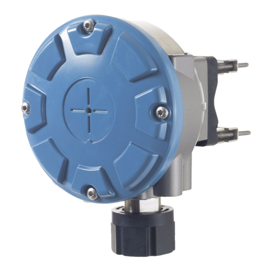
Reference Manual 300550EN, Rev AA Rosemount 2240S December 2010 2.2 COMPONENTS Figure 2-2. Rosemount 2240S components 1. Cover. 2. Glands (x 5) of type ½ — 14 NPT. 3. Lock nut for connection of Multi Spot Temperature sensors and Water Level Sensors (MST/WLS).
-
Page 13: System Overview
Reference Manual 300550EN, Rev AA Rosemount 2240S December 2010 2.3 SYSTEM Raptor is a state-of-the art inventory and custody transfer radar tank level gauging system. It is developed for a wide range of applications at refineries, OVERVIEW tank farms and fuel depots, and fulfills the highest requirements on performance and safety.
-
Page 14
Reference Manual 300550EN, Rev AA Rosemount 2240S December 2010 Figure 2-3. Raptor system architecture 2240S Temperature 5900S Radar Transmitter Level Gauge NON-HAZARDOUS AREA HAZARDOUS AREA TankMaster PC 2230 Display 2410 Tank Hub 3051S Pressure Transmitter Tankbus 2160 Field 5900S Radar… -
Page 15
Rosemount 2410 Tank Hub The Rosemount 2410 Tank Hub acts as a power supply to the connected field devices in the hazardous area using the intrinsically safe Tankbus. The 2410 collects measurement data and status information from field devices on a tank. -
Page 16
The four softkeys allow you to navigate through the different menus to provide all tank data, directly in the field. The Rosemount 2230 supports up to 10 tanks. Up to three 2230 displays can be used on a single tank. -
Page 17: Getting Started
7. Configure the 2410 Tank Hub by using the TankMaster WinSetup configuration software. 8. Configure the field devices, such as the 5900S and the 2240S, by using the TankMaster WinSetup configuration software. See the Rosemount Raptor System Configuration manual (Document No.
-
Page 18: Installation Procedure
Reference Manual 300550EN, Rev AA Rosemount 2240S December 2010 2.5 INSTALLATION Follow these steps for proper installation of the Rosemount 2240S: PROCEDURE 1. Install the temperature sensor/WLS (Section 3: MST/WLS Installation). 2. Review mounting considerations for the 2240S (“Installation Considerations” on page 4-2.
-
Page 19: Safety Messages
Reference Manual 300550EN, Rev AA Rosemount 2240S December 2010 Section 3 MST/WLS Installation Safety Messages ……page 3-1 Installation considerations .
-
Page 20
High voltage that may be present on leads could cause electrical shock: Avoid contact with leads and terminals. Make sure the main power to the Rosemount 2410 is off and the lines to any other external power sources are disconnected or not powered while wiring the gauge. -
Page 21: Installation Considerations
December 2010 3.2 INSTALLATION Multiple Spot Temperature sensor (MST) and Water Level Sensor (WLS) must be installed on the tank before installing the Rosemount 2240S Multi-input CONSIDERATIONS Temperature Transmitter. The MST/WLS is normally anchored to the bottom of the tank by attaching a weight at the end of the tube.
-
Page 22: Multiple Spot Temperature Sensor
“Installing a Temperature Sensor Tube” on page 3-8. Up to 16 Pt100 temperature elements can be connected to a Rosemount 2240S Multi-input Temperature Transmitter. 3.3.1…
-
Page 23: Installation On Floating Roof Tanks
Reference Manual Rosemount 2240S 300550EN, Rev AA December 2010 3.3.2 Installation on On floating roof tanks the temperature elements can be mounted in a still-pipe as illustrated in Figure 3-2 or in other suitable roof openings. Floating Roof Tanks Figure 3-2. Installation of…
-
Page 24: Custody Transfer Applications
A=12/(5-1)=3 m. The position of a temperature element is measured from the Tank Zero Level. See the Rosemount Raptor System Configuration Manual (Document no. 300510EN) for more information about how to use the TankMaster WinSetup software to configure temperature elements for average temperature calculations.
-
Page 25: Water Level Sensor
Reference Manual Rosemount 2240S 300550EN, Rev AA December 2010 3.4 WATER LEVEL The water level sensor probe, with integrated temperature elements, is attached at the lower end of the flexible protection tube. A weight is attached SENSOR to stabilize the tube as illustrated in Figure 3-4: Figure 3-4.
-
Page 26: Installing Atemperature Sensor Tube
3. When the tube is placed on the nozzle, adjust the position with the lock nuts. If the weight is placed at the end of the tube, it should barely touch the tank bottom. 4. Install the Rosemount 2240S Multi-Input Temperature Transmitter, see “Mechanical Installation” on page 4-3. NOTE Ensure that the flexible protection tube is in a vertical position to obtain correct measurement data.
-
Page 27: Safety Messages
High voltage that may be present on leads could cause electrical shock: Avoid contact with leads and terminals. Make sure the main power to the Rosemount 2240S is off and the lines to any other external power sources are disconnected or not powered while wiring the gauge.
-
Page 28: Installation Considerations
Ensure that the Rosemount 2240S is installed such that it is not exposed to higher pressure and temperature than specified in Appendix A: Reference Data.
-
Page 29: Mechanical Installation
3. Remove the plug that protects the cable (x4) entry at the bottom of the 2240S transmitter housing. Plug 4. Attach the 2240S transmitter on top of the temperature sensor tube. 5. Remove the cover and run the sensor wires into the terminal compartment. Sensor wires 6.
-
Page 30: Pipe Mounting
December 2010 4.3.2 Pipe Mounting To mount Rosemount 2240S on a pipe, do the following: 1. Use the four screws to fasten the bracket on a vertical pipe. A suitable pipe size is 1 to 2 1 — 2 inches inches.
-
Page 31: Wall Mounting
Rosemount 2240S December 2010 4.3.3 Wall Mounting To mount the Rosemount 2240S on a wall, do the following: 1. Drill four 9 mm (0.35 in.) holes in the wall to 94 mm (3.7 in.) fit the hole pattern of the bracket.
-
Page 32: Electrical Installation
M20×1.5, minifast and eurofast adapters are also available. Entries For remote mounting, the nut and sleeve on the Rosemount 2240S can be replaced with a M32 gland for connection of temperature sensors/WLS. Connections must be made in accordance with local or plant electrical codes.
-
Page 33
2410 Tank Hub which acts as the power supply for the devices on the Tankbus. The shield wire terminal in the Rosemount 2240S is not connected to ground. It only provides electrical continuity to daisy-chained Tankbus cables. Section 4. 2240S Installation… -
Page 34: Cable Selection
FISCO and Entity installations. In order to maintain the Ex ia coding the 2240S must be powered from a power supply coded Ex [ia]. However, most general FISCO power supplies are coded Ex [ib] and if the 2240S is powered from such a supply the 2240S coding automatically becomes Ex ib. This…
-
Page 35: The Raptor Tankbus
If the 2240S is not the last device in the fieldbus network, disconnect the termination jumper. See Figure 4-4 on page 4-11. Segment design When designing a FISCO fieldbus segment a few requirements need to be considered.
-
Page 36: Typical Installations
F fieldbus Installations OUNDATION system. In this case terminators are enabled in the Rosemount 2410 Tank Hub and a Raptor field device at the end of the network segment. Figure 4-3. Example of a Raptor Tankbus connection for a single…
-
Page 37: Tankbus Wiring
Rosemount 2240S December 2010 4.4.8 Tankbus Wiring Follow this procedure to connect the Rosemount 2240S: 1. Ensure that the power supply is switched off. 2. Loosen the four screws and remove the cover on the terminal compartment. Figure 4-4. 2240S terminal…
-
Page 38: Daisy-Chain Connection
M20 glands. A typical wiring diagram of a Raptor system with a Rosemount 2240S is illustrated in Figure 4-5. In the example below the 2240S is daisy-chained to a Rosemount 5900S Radar Level Gauge and a Rosemount 2230 Graphical Field Display: Figure 4-5.
-
Page 39: Temperature Element Wiring
2240S housing. In case the 2240S is mounted on a pipe or a wall (see “Mechanical Installation” on page 4-3), the sleeve and nut can be replaced by an M32 cable gland, see Figure 2-2 on page 2-2.
-
Page 40
3. Run the sensor wires through the sleeve at the bottom of the transmitter housing, see Figure 4-6. If the 2240S is mounted on a wall or pipe (remote mounting), run the sensor wires through the appropriate cable gland/conduit entry, see Figure 2-2 on page 2-2. -
Page 41
Figure 4-8. 3-wire individual spot b1 c1 Up to 16 channels Individual return Figure 4-9. 4-wire individual spot a1 b1 c1 d1 a2 b2 a3 b3 b16 c16 d16 Up to 10 channels Up to 16 channels Individual return Section 4. 2240S Installation 4-15… -
Page 42: Water Level Sensor Wiring
3. Run the sensor wires through the sleeve at the bottom of the transmitter housing, see Figure 4-10. If the 2240S is mounted on a wall or pipe (remote mounting), run the sensor wires through the appropriate cable gland/conduit entry, see Figure 2-2 on page 2-2.
-
Page 43: Safety Messages
Reference Manual 300550EN, Rev AA Rosemount 2240S December 2010 Section 5 Configuration/Operation Safety Messages ……page 5-1 Introduction .
-
Page 44: Introduction
It is important that configuration is properly prepared by listing the appropriate Modbus addresses, device tags, and tank tags. 5.2.1 Configuration Basically, a Rosemount 2240S can be installed and configured by one of the following methods: procedure • As part of the installation of a Rosemount 2410 Tank Hub. This is the standard procedure when a new system is installed, see the Raptor System Configuration Manual (Document no.
-
Page 45: Basic Configuration
Minimum distance between element and surface for element to be included in average calculation, see “Insert Distance” on page 5-5. Auto Sensor A DIP switch on the Rosemount 2240S can be set to Configuration automatically configure the temperature sensor, see “DIP Switches” on page 5-13.
-
Page 46
Reference Manual 300550EN, Rev AA Rosemount 2240S December 2010 Temperature Element Positions The temperature elements are numbered from the bottom of the tank and upwards. Enter the position of each element, measured as the distance from the Zero Level (Dipping Datum Plate) to the temperature element. If you use average temperature elements, enter the position of the terminating level of each sensor element. -
Page 47
Reference Manual 300550EN, Rev AA Rosemount 2240S December 2010 Insert Distance You can specify a minimum distance between the product surface and the first temperature spot element to be included in the average temperature calculation. If the temperature spot element is within or above the Insert Distance, the element will be excluded from the calculation. -
Page 48: Water Level Sensor Calibration
2. Wait five minutes. 3. Press the ZERO button on the Rosemount 2240S for three seconds to begin calibration (see Figure 5-3). 4. Wait for the Status LED to turn from a steady light to normal LED status (2 sec.
-
Page 49: Water Level Sensor Measuring Range
Reference Manual 300550EN, Rev AA Rosemount 2240S December 2010 5.3.3 Water Level Sensor Measuring Range Reference Points The WLS has two reference points, the Upper Reference Point and the Water Zero Level, which are marked on the probe. The positions of the Upper Reference Point and Water Zero Level are given in Figure 5-4 below: Figure 5-4.
-
Page 50
This can be useful in case there is no distinct interface between water and oil. See the Rosemount Raptor System Configuration Manual (Document no. 300510EN) for information about how to configure the Dead Zones. -
Page 51
The conversion from the WLS reference system to the tank reference system is handled by the Rosemount 2240S. In the tank reference system, the Lower Sensor Limit (0%) and the Upper Sensor Limit (100%) are given by the… -
Page 52
Reference Manual 300550EN, Rev AA Rosemount 2240S December 2010 Configuration Examples The configuration of the WLS can basically be divided into three cases as illustrated below: Table 5-2. WLS configuration The Water Zero Level is below the Tank The Water Zero Level is equal to the Tank The Water Zero Level is above the Tank Zero Level. -
Page 53: Led Signals
Reference Manual 300550EN, Rev AA Rosemount 2240S December 2010 5.4 LED SIGNALS The Rosemount 2240S Multi-input Temperature Transmitter is equipped with Light Emitting Diodes (LED) in order to indicate status and communication. 5.4.1 Status LED The status LED indicates: •…
-
Page 54: Communication Leds
Water Level Sensor (WLS) is connected, two LED signals indicate that measurement and status information is communicated over the Sensor bus to the 2240S • two LEDs indicate that the 2240S communicates over the Tankbus with a Rosemount 2410 Tank Hub Figure 5-7. Communication LEDs…
-
Page 55: Switches And Reset Buttons
Rosemount 2240S December 2010 5.5 SWITCHES AND RESET BUTTONS 5.5.1 DIP Switches The Rosemount 2240S is equipped with four DIP switches, see Figure 5-8. Figure 5-8. DIP Switches DIP Switches The switches control the following settings: Table 5-3. DIP switches Number…
-
Page 56: Reset Button
Cu90 Pt100 In the TankMaster WinSetup configuration tool, automatic configuration can be enabled in the configuration window for the 2240S transmitter (2240 MTT Temperature Sensor tab in the 22XX ATD window). See configuration of ATD devices in theRosemount Raptor System Configuration Manual (Document no.
-
Page 57: Configuration Using Tankmaster Winsetup
5.6 CONFIGURATION USING TANKMASTER WINSETUP The TankMaster software package provides you with powerful and easy-to-use tools for installation and configuration of a Rosemount Raptor tank gauging system. See the Rosemount Raptor System Configuration Manual (Document no. 300510EN) for information about how to use TankMaster WinSetup to configure a Raptor system.
-
Page 58
Reference Manual 300550EN, Rev AA Rosemount 2240S December 2010 Section 5. Configuration/Operation 5-16… -
Page 59: Safety Messages
Reference Manual 300550EN, Rev AA Rosemount 2240S December 2010 Section 6 Service and Troubleshooting Safety Messages ……page 6-1 Service .
-
Page 60: Service
WinSetup configuration tool, most Holding Registers can be edited simply by typing a new value in the appropriate value input field. To view Input or Holding Registers for a Rosemount 2240S, do the following: 1. Start the TankMaster WinSetup program.
-
Page 61: Editing Holding Registers
WinSetup refer to the internal register area of the 2410. Therefore, for tank 1 you will have to add 10000 to the 2240S internal register number as given by Table 6-4 in order to find the register presented by WinSetup. For tank 2 (requires a 2410 with the multi-tank option) you will have to add 12000, for tank 3 you will have to add 14000, and so on.
-
Page 62: Diagnostics
Reference Manual 300550EN, Rev AA Rosemount 2240S December 2010 6.2.3 Diagnostics The TankMaster WinSetup program lets you view the current device status in the View Diagnostic Registers window. It shows a selection of database registers that gives you an instant view of how the device operates. You may configure the window by adding registers of special interest.
-
Page 63: Ground Fault Detection
December 2010 6.2.4 Ground Fault The Rosemount 2240S has a built-in function for ground fault detection. When the ground fault detector is enabled, a faulty temperature sensor is indicated Detection in a status register (see “Temperature Element Status” on page 6-20). A single fault will affect the measurement on all channels.
-
Page 64: Reset And Wls Calibration
Reset and WLS Resetting the 2240S Multi-input Temperature Transmitter Calibration The RESET button can be used to force a restart of the 2240S Multi-input Temperature Transmitter. Restarting the 2240S has the same effect as switching off and on the power supply.
-
Page 65: Device Error Led Signals
Rosemount 2240S December 2010 6.2.6 Device Error LED Inside the transmitter housing, the Rosemount 2240S has a red Light Emitting Diode (LED) that presents the current transmitter status. The LED uses Signals different blinking sequences for presentation of various error types.
-
Page 66
Reference Manual 300550EN, Rev AA Rosemount 2240S December 2010 Example Error code 4 (Other memory error) is displayed as the following LED flash sequence: Figure 6-4. Example of an error code flash sequence Seconds NOTE! In case there are several simultaneous errors only the first detected error is indicated by the LED. -
Page 67: Test And Simulation
6.2.7 Test and Test Terminal for Temperature Elements Simulation The Rosemount 2240S has a built-in simulator for temperature elements which allows you to verify the measuring electronics. The built-in test facility comprises one 100 0.1 Ohm resistor and four 10 ±…
-
Page 68: Communication
December 2010 6.2.8 Communication The Rosemount 2240S has four yellow LEDs that indicate communication on the Sensor Bus and the Tankbus. The two LEDs on the left indicate Receive and Transmit for the Sensor bus. The two LEDs on the right indicate Receive and Transmit for the Tankbus.
-
Page 69: Troubleshooting
• Contact Emerson Process Management/Rosemount TankGauging service department. Software failure • Restart the 2240S with the Reset button or by using the Restart command in TanMaster WinSetup. • Restart all devices by disconnecting and connecting the power supply to the 2410 Tank Hub.
-
Page 70
Communicaton Unit. Incorrect configuration of FCU 2160 • Check the Modbus communication address specified for the ATD device that represents the 2240S Multi-input Temperature Transmitter in the 2160 FCU Slave Database. For the single tank version, this address is equal to the Modbus address of the 2410 Tank Hub itself. -
Page 71
Tank Hub. • Check configuration of the FCU 2160 slave database. Configuration • Check that the 2240S is properly configured. See the Raptor System Configuration Manual (Document no. 300510EN) for more information on how to use TankMaster Winsetup for configuration of temperature elements connected to the Rosemount 2240S. -
Page 72
Possible cause Action Configuration can not be saved Write protection switch is set to the ON • Check write protection switch on the 2240S, see “DIP position Switches” on page 5-13. The Status LED is blinking error 2240S transmitter, temperature element, •… -
Page 73: Device Status
WinSetup refer to the internal register area of the 2410. Therefore, for tank 1 you will have to add 10000 to the 2240S internal register number as given by Table 6-4 in order to find the register presented by WinSetup. For tank 2 (requires a 2410 with the multi-tank option) you will have to add 12000, for tank 3 you will have to add 14000, and so on.
-
Page 74
MinIntTemp Input register no. 110. Minimum measured internal temperature. MaxIntTemp Input register no. 112. Maximum measured internal temperature. (1) The register number refers to the internal Input Register in the 2240S database. Section 6. Service and Troubleshooting 6-16… -
Page 75: Device Warnings
Bit 10: Sensor bus not supported in model code Bit 11: Invalid model code string Bit 12: Invalid model code (1) The register number refers to the internal Input Register in the 2240S database. Section 6. Service and Troubleshooting 6-17…
-
Page 76: Device Errors
Contact Emerson Process Number of hidden errors Management/Rosemount TankGauging numOther errors Input register no. 1134. service department. Number of other errors. (1) The register number refers to the internal Input Register in the 2240S database. Section 6. Service and Troubleshooting 6-18…
-
Page 77: Measurement Status For The Wls
Input register no. 502. Primary value from the connected sensor Unit Input register no. 504. Measurement unit such as Feet, Meters, Inches etc. (1) The register number refers to the internal Input Register in the 2240S database. Section 6. Service and Troubleshooting 6-19…
-
Page 78: Temperature Element Status
Temperature measured by element no. 16. See above. Status_16 Input register no. 262. Status for temperature element 16. See above. (1) The register number refers to the internal Input Register in the 2240S database. Section 6. Service and Troubleshooting 6-20…
-
Page 79: Appendix A Specifications
Rosemount 2240S Multi-Input Temperature Transmitter Number of spot elements and wiring Up to 16 RTD spot elements or averaging sensors can be connected to a 2240S. Rosemount temperature / water level sensors (models 565, 566 and 765) Three wiring types can be used: •…
-
Page 80
Mechanical Housing material Polyurethane-coated die-cast aluminum Installation The 2240S can be installed directly on top of the temperature / water level sensor or remotely installed on a 33.4-60.3 mm 1 to 2 in.) pipe or on a wall Dimensions See “Dimensional drawings” on page A-3 Weight 2.8 kg (6.2 lbs) -
Page 81: Dimensional Drawings
Reference Manual 300550EN, Rev AA Rosemount 2240S December 2010 A.2 DIMENSIONAL DRAWINGS Figure A-1. Dimensional drawings 244 mm (9 in.) 177 mm (7 in.) 143 mm (6 in.) Optional tag plate Optional mounting kit Nuts to adjust sensor position. Adjustable threads: ±…
-
Page 82: Ordering Information
3-wire (individual or common return) None For water level, no temperature sensors Code (Pos 5) Auxiliary Inputs Note Rosemount 765 temperature and water level sensor input None Code (Pos 6) Tankbus: Power and Communication Note Bus powered 2-wire F ™ fieldbus (IEC 61158)
-
Page 83
Model Code Example: 2240S – P 16 4 A F I1 0 A 1 M — ST (1) Temperature sensors of Pt-100 or Cu-90 type, for use in -200 to 250 ºC (-328 to 482 ºF), can be connected to the Rosemount 2240S. -
Page 84
Reference Manual 300550EN, Rev AA Rosemount 2240S December 2010 Appendix A. Reference Data… -
Page 85
Reference Manual 300550EN, Rev AA Rosemount 2240S December 2010 Appendix B Product Certifications Safety messages ……page B-1 EU Conformity . -
Page 86: Appendix B Product Certifications
B.2 EU CONFORMITY The EC declaration of conformity for all applicable European directives for this product can be found on the Rosemount website at www.rosemount.com. A hard copy may be obtained by contacting our local sales representative. Appendix B. Product Certifications…
-
Page 87: Hazardous Locations Certifications
Reference Manual 300550EN, Rev AA Rosemount 2240S December 2010 B.3 HAZARDOUS The Rosemount 2240S Multi-Input Temperature Transmitters that have the following labels attached have been certified to comply with the requirements LOCATIONS of the approval agencies noted. CERTIFICATIONS B.3.1 Factory Mutual Certificat of Compliance: 3035518.
-
Page 88
Reference Manual 300550EN, Rev AA Rosemount 2240S December 2010 RTD Terminals =5.9V, l =398mA, P =585mW Group IIC: C 43µF, L 0.2mH Group IIB: C =unlimited, L 0.7mH Group IIA: C =unlimited, L 1.8mH… -
Page 89: Factory Mutual Canadian Approvals
=5.32W, C =2.2nF, L =1.5µH FISCO SYSTEM when supplied from Rosemount 2410 Tank Hub Class 1 Zone 1 Ex ib [ia IIC] IIB FISCO SYSTEM Entity (Fieldbus Terminals) Intrinsically Safe for Class I, II, III Division 1, Groups A, B, C, D, E, F and G Temperature Class T4, Ambient Temperature Limits: -50 °C to +70 °C…
-
Page 90
Reference Manual 300550EN, Rev AA Rosemount 2240S December 2010 RTD Terminals =5.9V, l =398mA, P =585mW Group IIC: C 43µF, L 0.2mH Group IIB: C =unlimited, L 0.7mH Group IIA: C =unlimited, L 1.8mH… -
Page 91: European Atex Directive Information
Rosemount 2240S December 2010 B.3.3 European ATEX The Rosemount 2240S Multi-Input Temperature Transmitters that have the following label attached have been certified to comply with Directive 94/9/EC Directive Information of the European Parliament and the Council as published in the Official Journal of the European Communities No.
-
Page 92
Reference Manual 300550EN, Rev AA Rosemount 2240S December 2010 Entity (Fieldbus Terminals) Ex ia IIC T4 (-50 °C Ta • +70 °C) • =30V, I =300mA, P =1.3W, C =2.2nF, L =1.5µH RTD Terminals =5.9V, l… -
Page 93: Iecex Approval
• =17.5V, I =380mA, P =5.32W, C =2.2nF, L =1.5µH FISCO SYSTEM when supplied from Rosemount 2410 Tank Hub (IECEx FMG 10.0005) Ex ib IIB [ia IIC Ga] Gb T4 FISCO SYSTEM (-50 °C Ta •…
-
Page 94
Reference Manual 300550EN, Rev AA Rosemount 2240S December 2010 Sensorbus Terminal =6.6 V, l =223 mA, P =0.363 W 22µF, L 0.7mH Group IIC: C 500µF, L 3.3mH Group IIB: C 6mH Group IIA: C =unlimited, L Special Conditions for Safe Use (X) The enclosure contains aluminum and is considered to present a potential risk of ignition by impact or friction. -
Page 95: Approval Drawings
9240040-976 System Control Drawing for hazardous location installation of intrinsically safe FM ATEX and FM IECEx approved apparatus See the “Manuals & Drawings” CD ROM that is shipped with the Rosemount 2240S Multi-Input Temperature Transmitter for electronic copies of the system control drawings.
-
Page 96
Reference Manual 300550EN, Rev AA Rosemount 2240S December 2010 Appendix B. Product Certifications B-12… -
Page 97
Reference Manual 300550EN, Rev AA Rosemount 2240S December 2010 Index Numerics Configuration ….5-2 conversion method ..5-3 2160 Field Communication Unit 2-5 Electrical Installation . -
Page 98
SW error ….6-7 Rosemount 2230 … 2-1 Upper Reference Point ..5-7 LED Signals Rosemount 2240S . -
Page 100
300550EN, Rev AA Rosemount 2240S December 2010 Rosemount and the Rosemount logotype are trademarks of Rosemount Inc. HART is a trademark of the HART Communication Foundation. PlantWeb is a trademark of one of the Emerson Process Management group of companies.
|
Detail Specifications: 921/921555-rosemount_2240s.pdf file (07 Mar 2023) |
Accompanying Data:
Emerson Rosemount 2240S Transmitter PDF Reference Manual (Updated: Tuesday 7th of March 2023 03:24:10 AM)
Rating: 4.2 (rated by 19 users)
Compatible devices: Rosemount, Rosemount 56, Rosemount Wireless Permasense WT210, Rosemount 2051G, Rosemount 4600, wirelessHART Rosemount Series, Rosemount 3051, OCX 8800.
Recommended Documentation:
Text Version of Reference Manual
(Ocr-Read Summary of Contents, UPD: 07 March 2023)
-
113, 103 Reference Manual 00809-0100-2240, Rev DA Configuration/Operation October 2017 Configuration/Operation 6. Select the Configure>Alert Setup option. 7. Select the desired tab (FF I/O Board, 2240S Multi-input Temperature Transmitter, Water Level Sensor, Simulation Alerts). 8. Configure alerts for the different error types. The first time this window is opened, the default setup…
-
132, 122 Reference Manual 00809-0100-2240, Rev DA Service and Troubleshooting October 2017 Service and Troubleshooting Table 6-4. Status registers for the Rosemount 2240S Multi-input Temperature Transmitter Message Description Action Device Status Input register no. 100 (1) . Bit 1: Device warning Bit 7: Device error Bit 8: Simulation Mode Active Bit 9: PTB Mode Active Bit 10: PTB Re…
-
52, Emerson Rosemount 2240S 42 Reference Manual 00809-0100-2240, Rev DA Rosemount ™ 2240S Installation October 2017 Rosemount ™ 2240S Installation 4.4.10 Daisy-chain connection The Rosemount Tank Gauging system supports daisy-chain connection of devices to the Tankbus. To daisy-chain the Rosemount 2240S to other devices do the following: 1. Make sure the power supply is switched o…
-
148, 138 Reference Manual 00809-0100-2240, Rev DA Service and Troubleshooting October 2017 Service and Troubleshooting 6.8.3 Viewing input and holding registers To view Input or Holding registers for a Rosemount 2240S: 1. In AMS Device Manager open Service Tools as shown in “Service tools window” on page 134. 2. In the Navigation Pane select the Maintenance (A) option 3. S…
-
97, Emerson Rosemount 2240S 87 Reference Manual 00809-0100-2240, Rev DA Configuration/Operation October 2017 Configuration/Operation Function Check Alarms A Function Check alarm indicates that the device is temporary non-valid due to some activities, for example maintenance, on the device. There are five parameters associated with FD_CHECK_ALM, they are described below. FD_CHECK_MAP The FD_CHECK_MAP paramete…
-
32, 22 Reference Manual 00809-0100-2240, Rev DA MST/WLS Installation October 2017 MST/WLS Installation 3.3 Multiple Spot Temperature sensor A Multiple Spot Temperature sensor (MST) typically measures the temperature with a number of Pt100 elements placed at different heights to provide a temperature profile and average temperature of the product. The spot elements are placed in a …
-
74, 64 Reference Manual 00809-0100-2240, Rev DA Configuration/Operation October 2017 Configuration/Operation 5.5.2 Reset button Use the reset button to force a restart of the processor (for more information see “Reset and WLS calibration” on page 112). Figure 5-11. Reset button A: Reset A
… -
153, 143 Specifications and Reference Data Specifications and Reference Data October 2017 Reference Manual 00809-0100-2240, Rev DA A.5 Electrical specifications A.5.1 Power supply FISCO: 9.0-17.5 VDC polarity insensitive Entity: 9.0-30.0 VDC polarity insensitive A.5.2 Internal power consumption 0.5 W A.5.3 Bus current draw 30 mA A.5.4 Tankbus cabling…
-
35, Emerson Rosemount 2240S 25 Reference Manual 00809-0100-2240, Rev DA MST/WLS Installation October 2017 MST/WLS Installation 3.4 Water Level Sensor The water level sensor (WLS) probe, with integrated temperature elements, is attached at the lower end of the flexible protection tube. A weight is attached to stabilize the tube as illustrated in Figure 3-4. At the upper part of the sensor probe, nuts are placed at the…
-
134, 124 Reference Manual 00809-0100-2240, Rev DA Service and Troubleshooting October 2017 Service and Troubleshooting 6.3.3 Device errors Tab le 6-6 shows a list of error messages for the Rosemount 2240S Multi-input Temperature Transmitter. The error messages may appear on the display of a Rosemount 2410 Tank Hub and in the Rosemount Tankmaster program. Detailed…
-
147, 137 Reference Manual 00809-0100-2240, Rev DA Service and Troubleshooting October 2017 Service and Troubleshooting In the Device Status tab, check boxes indicate the current status of the device grouped in separate categories. See also “Device status” on page 121.
…
Recommended Instructions:
SC-5006, HW-C1260TVE-E, Spyder, KIM010, W010


-
FRITDEENTRASMETTITORE TELEFONICO BIDIREZIONALE GSMTRANSMETTEUR TÉLÉPHONIQUE BIDIRECTIONNEL GSMDICHIARAZIONE DI CONFORMITA’: Con la presente SILENTRON S.p.A dichiara che l’appa …
5155 VOCALPHONE SENIOR 16
-
Carrier frequency …………………………433,92 MHzModulation ………………………………….AM/ASKN° channels ………………………………..1E.r.p. ………………………………………….300 uWBattery type ………………………………..ER14505 LithiumOperating voltage ………………………..3,6 VdcCurrent consumption ………….. …
ERONE TTHS2641E1 4
-
TI382P/00/EN/06.09No. 71095431Technical InformationDeltabar S PMD70/75, FMD76/77/78Differential pressure measurementDifferential pressure transmitter with ceramic and silicon sensorsOverload-resistant and function-monitored, Communication via HART, PROFIBUS PA or FOUNDATION FieldbusApplicationThe Deltabar S differential pressure transmitter is used for the following measuring ta …
Deltabar S PMD70 84
-
MANUALE ISTRUZIONIMANUAL INSTRUCTIONSNOTICE DE MONTAGE ET D’EMPLOIGEBRAUCHSANWEISUNGENMANUAL DE INSTRUCCIONESVM546UNIVERSAL SD — USB PLAYERFM TRANSMITTER PHONOCAR S.p.A. — Via F.lli Cervi, 167/C42124 Reggio Emilia (Italy) Tel. ++39 0522 941621 — Fax ++39 0522 942452www.phonocar.com — e-mail:[email protected]•Porta/Slot USB-microSD/MMC 16GB• Ingresso AUX IN / …
VM546 4
Additional Information:
Popular Right Now:
Operating Impressions, Questions and Answers:
Table of Contents for Rosemount 2240S:
-
Reference Manual 300550EN, Rev AA December 2010 1-3 Rosemount 2240S Section 1. Introduction 1.3 TECHNICAL DOCUMENTATION The Raptor System includes the following documents: • Raptor Technical Description (704010EN) • Rosemount 5900S Reference Manual (300520EN) • Rosemount 2410 Reference Manual (300530EN) • Rosemount 2240S Reference Manual (300550EN) • Rosemount 2230 Reference Manual (300560EN) • Raptor System Configuration Manual (300510EN) • Rosemount 5300 Product Data Sheet (00813-0100-4530) • Rosemount 5400 Product Data Sheet (00813-010
-
Reference Manual 300550EN, Rev AA December 2010 6-5 Rosemount 2240S Section 6. Service and Troubleshooting 6.2.4 Ground Fault Detection The Rosemount 2240S has a built-in function for ground fault detection. When the ground fault detector is enabled, a faulty temperature sensor is indicated in a status register (see “Temperature Element Status” on page 6-20). A single fault will affect the measurement on all channels. If
-
Reference Manual 300550EN, Rev AA December 2010 Rosemount 2240S 6-16 Section 6. Service and Troubleshooting Device error Input register no. 102. Bit 0: RAM Error Bit 1: FPROM Error Bit 2: HREG Error Bit 3: SW Error Bit 4: Other memory error Bit 6: Reserved for Display error Bit 7: Reserved for Modem error Bit 9: Internal temperature error Bit 10: Other HW error Bit 11 : Measurement Error Bit 12: Configuration error See “Device Errors” on page 6-18 for more information on the various error types. Contact Emerson Process Management/Ros
-
Reference Manual 300550EN, Rev AA December 2010 6-15 Rosemount 2240S Section 6. Service and Troubleshooting 6.3.1 Device Status Table 6-4 shows a list of device status messages for the Rosemount 2240S Multi-input Temperature Transmitter. Messages may appear on the display of a Rosemount 2410 Tank Hub, and in the Rosemount Tankmaster program (See “Viewing Input and Holding Registers” on page 6-2 for more information on how to view Input registers). TankMaster WinS
-
Reference Manual 300550EN, Rev AA December 2010 6-17 Rosemount 2240S Section 6. Service and Troubleshooting 6.3.2 Device Warnings Table 6-5 shows a list of warning messages for the Rosemount 2240S Multi-input Temperature Transmitter. The warnings may appear on the display of a Rosemount 2410 Tank Hub and in the Rosemount Tankmaster program. Warnings are less serious than errors. Detailed information about the different warning messages can be found in Input registers 1050 to 1070 as shown in Table 6-5. See “Viewing Input and Holding Registers” on
-
Reference Manual 300550EN, Rev AA December 2010 Rosemount 2240S 5-2 Section 5. Configuration/Operation 5.2 INTRODUCTION This chapter provides information about configuration of the Rosemount 2240S Multi-input Temperature Transmitter regardless of the configuration tool used. However, you will find frequent references to TankMaster WinSetup, which is the recommended configuration tool. It is important that configuration is properly prepared by listing the appropriate Modbus addresses, device tags, and tank tags. 5.2.1 Con
-
Reference Manual 300550EN, Rev AA December 2010 5-13 Rosemount 2240S Section 5. Configuration/Operation 5.5 SWITCHES AND RESET BUTTONS 5.5.1 DIP Switches The Rosemount 2240S is equipped with four DIP switches, see Figure 5-8. Figure 5-8. DIP Switches The switches control the following settings: Table 5-3. DIP switches The Simulate Switch The Simulate switch is used to simulate a resistance value from temperature elements. The switch returns from “ON” to “OFF” after power is app
-
Reference Manual 300550EN, Rev AA December 2010 Rosemount 2240S B-10 Appendix B. Product Certifications Sensorbus Terminal U o =6.6 V, l o =223 mA, P o =0.363 W Group IIC: C o 22µF, L o 0.7mH Group IIB: C o 500µF, L o 3.3mH Group IIA: C o =unlimited, L o 6mH Special Conditions for Safe Use (X) The enclosure contains aluminum and is considered to present a potential risk of ignition by impact or friction. Care must be taken during install
-
Reference Manual 300550EN, Rev AA December 2010 5-3 Rosemount 2240S Section 5. Configuration/Operation 5.3 BASIC CONFIGURATION Temperature elements and a water level sensor can be connected to the Rosemount 2240S Multi-input Temperature Transmitter. 5.3.1 Temperature elements The following configuration options are supported for temperature elements connected to a Rosemount 2240S Multi-input Temperature Transmitter: Table 5-1. Rosemount 2240S temperature
-
Reference Manual 300550EN, Rev AA December 2010 Rosemount 2240S 5-12 Section 5. Configuration/Operation 5.4.2 Communication LEDs There are two pairs of LEDs that indicate communication status for the Rosemount 2240S Multi-input Temperature Transmitter: • when a Water Level Sensor (WLS) is connected, two LED signals indicate that measurement and status information is communicated over the Sensor bus to the 2240S • two LEDs indicate that the 2240S communicates over the Tankbus with a Rosemount 2410 Tank Hub Figure 5-7. Communication
Questions, Opinions and Exploitation Impressions:
You can ask a question, express your opinion or share our experience of Rosemount 2240S device using right now.
Quick Start Guide
February 2023
Contents
About this guide…………………………………………………………………………………………………………… 3
Overview……………………………………………………………………………………………………………………… 6
General information…………………………………………………………………………………………………….. 8
Sensor installation……………………………………………………………………………………………………….. 9
Rosemount 2240S Installation……………………………………………………………………………………. 17
Configuration and operation……………………………………………………………………………………….39
2
Emerson.com/Rosemount
Технические характеристики
- Погрешность
- ±0.05 °C (±0.09 °F) На всем диапазоне измерения и при температуре окружающей среды 20 °C (68 °F).
- Погрешность, вызванная влиянием температуры окружающей среды
- ±0.05 °C (±0.09 °F)
- Диапазон измерения
- Для Pt-100 от -200 до 250 °C (от -328 до 482 °F)
- Разрешение
- ±0.1 °C (±0.1 °F) according to API chapter 7 and 12.
- Количество точечных элементов измерения температуры
- До 16 точечных термопреобразователей сопротивления:
• 3-проводной тип подключения с общим или отдельным обратным проводом
• 4-проводной тип подключения с отдельным обратным проводом.
- Тип датчика
- Pt-100 (в соответствии с IEC/EN60751, ASTM E1137) и Cu-90
- Протокол передачи данных
- Foundation™ Fieldbus для подключения к Rosemount 2410 с самонастраивающейся хост-системой Tankbus или Foundation™ Fieldbus.
- Сертификация типа коммерческого учета
- Сертификат рабочих характеристик OIML R85:2008 и государственная сертификация, например, PTB, NMI и т. п.
- Функция эмуляции
- Возможность интеграции в устаревшие системы учета резервуаров.
- Метрологическое пломбирование
- Поддерживает протоколы связи от других производителей. Например, Enraf, L&J Tankway, Varec Mark/Space, Whessoe, GPE, Sakura и Tokyo Keiso.
- Источник питания
- • FISCO: 9,0–17,5 В пост. тока, не чувствительно к смене полярности (например, от модуля связи Rosemount 2410).
• Устройство: 9,0 — 30,0 В пост. тока, не чувствительно к смене полярности.
- Температура окружающей среды
- от -40 до +70 °C (от -40 до +158 °F).
Минимальная температура включения –50 °C
Особенности
- Измерение температуры с высокой стабильностью для точного расчета запасов и коммерческого учета при отгрузке потребителям для соответствия главе 7.3 API
- Точность преобразования температуры ±0,05 °C (±0,09 °F)
- Подключение до 16 трех- или четырехпроводных температурных элементов
- В комплект входит встроенный датчик уровня воды
- Простота установки обеспечивается искробезопасной двухпроводной полевой шиной с обеспечением питания.
- Аналогичные товары
Вся информация на сайте о товарах и ценах носит справочный характер и не является публичной офертой. Производитель оставляет за собой право изменять характеристики товара, его внешний вид и комплектность без предварительного уведомления продавца