-
Contents
-
Table of Contents
-
Troubleshooting
-
Bookmarks
Quick Links
00809-0100-4727
English
Rev. CA
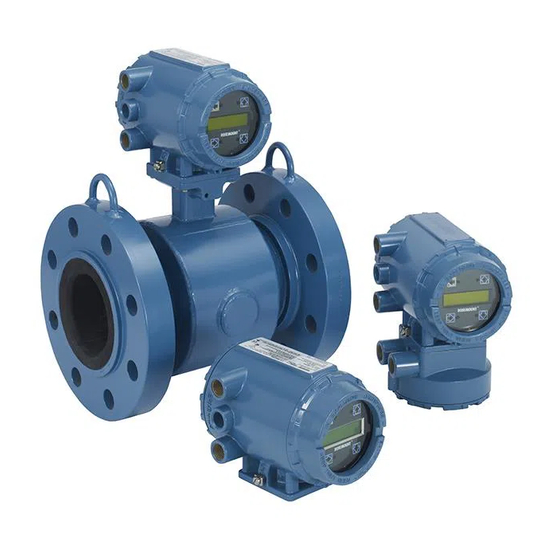
Series 8700 Magnetic
Flowmeter Flowtubes
Related Manuals for Rosemount Series 8700
Summary of Contents for Rosemount Series 8700
-
Page 1
00809-0100-4727 English Rev. CA Series 8700 Magnetic Flowmeter Flowtubes… -
Page 3
For information on Rosemount nuclear-qualified products, contact your local Rosemount Sales Representative. Rosemount, the Rosemount logotype, and SMART FAMILY are registered trademarks of Rosemount Inc. HART is a registered trademark of the HART Communication Foundation. Tefzel and Teflon are registered trademarks of E.I. du Pont de Nemours & Co. -
Page 5: Table Of Contents
Table of Contents IMPORTANT Procedures and instructions in this manual may require special precautions to ensure the safety of the personnel performing the operations. Refer to the safety messages at the beginning of each section before performing any operations. SECTION 1 Manual Scope .
-
Page 6
Primary and Secondary Devices ……B-2 Magnetic Flowmeter Oper- Series 8700 Magnetic Flowmeter Flowtube ….B-2 ating Principles Series 8700 Magnetic Flowmeter Transmitter . -
Page 7: Manual Scope
Section Introduction MANUAL SCOPE The Rosemount Series 8700 Magnetic Flowmeter System combines separate flowtube and transmitter units. This manual is designed to assist in the installation and operation of Rosemount Model 8705, Model 8707 High- Signal, and Model 8711 Magnetic Flowmeter Flowtubes.
-
Page 8: System Description
Rosemount Series 8700 Magnetic Flowmeter Flowtube SYSTEM DESCRIPTION A Rosemount Series 8700 Magnetic Flowmeter System measures volumetric flow rate by detecting the velocity of a conductive liquid that passes through a magnetic field. The system consists of two major assemblies: the Model 8705, Model 8707 High-Signal, or Model 8711 Magnetic Flowmeter Flowtubes combined with the Model 8712C/U/H or the Model 8732C Magnetic Flowmeter Transmitters.
-
Page 9: Safety Messages
Section Installation This section covers the steps required to physically install the flowtube. Detailed information regarding operation planning and magnetic flowmeter theory is found in the appendices. SAFETY MESSAGES Instructions and procedures in this section may require special precautions to ensure the safety of the personnel performing the operations.
-
Page 10: Step 2: Mounting
Conventional tools, equipment, and accessories (bolts, gaskets, MOUNTING and grounding hardware) are required. Calibration Rosemount flowtubes are wet calibrated at the factory. They do not need further calibration during installation. To ensure specification accuracy over widely varying process conditions, Upstream/…
-
Page 11: Flowtube Orientation
Installation Flowtube Orientation The flowtube should be installed in a position that ensures the flowtube remains full during operation. Horizontal or inclined positions are preferred. Figures 2-3, 2-4, and 2-5 show the proper flowtube orientation for the most common installations. The following orientations ensure that the electrodes are in the optimum plane to minimize the effects of entrapped gas.
-
Page 12: Flow Direction
Rosemount Series 8700 Magnetic Flowmeter Flowtube FIGURE 2-5. FLOW Incline or Decline Orientation. FLOW Flow Direction The flowtube should be mounted so that the FORWARD end of the flow arrow, shown on the flowtube identification tag, points in the direction of flow through the tube (see Figure 2-6).
-
Page 13: Step 3: Installation Of Model 8705 And Model 8707 High-Signal
Installation STEP 3: The following drawings should be used as a guide in the installation of the Model 8705 and Model 8707 High-Signal Flowtubes. Refer to page INSTALLATION OF MODEL 2-7 for installation of the Model 8711 Flowtube. 8705 AND MODEL 8707 HIGH-SIGNAL Gaskets The flowtube requires a gasket at each of its connections to adjacent devices…
-
Page 14: Flange Bolts
Rosemount Series 8700 Magnetic Flowmeter Flowtube Flange Bolts Flowtube sizes and torque values for both Class 150 and Class 300 flanges are listed in Table 2-1. Tighten flange bolts in the incremental sequence, shown in Figure 2-9. See Tables 5-4, 5-4, and 5-5 for bolt sizes and hole diameters.
-
Page 15: Step 3: Installation Of Model 8711
Installation STEP 3: The following section should be used as a guide in the installation of the Model 8711 Flowtube. INSTALLATION OF MODEL 8711 Gaskets The flowtube requires a gasket at each of its connections to adjacent devices or piping. The gasket material selected must be compatible with the process fluid and operating conditions, and must not damage the liner.
-
Page 16: Flange Bolts
Rosemount Series 8700 Magnetic Flowmeter Flowtube Alignment with Centering Sleeves Follow the instructions below for the 1.5- through 8-inch (40 to 200 mm) line sizes if you received two centering sleeves instead of centering rings: 1. Insert the two studs for the bottom side of the flowtube, with the centering sleeves, between the pipe flanges.
-
Page 17
Installation TABLE 2-3. Grounding Installation. Grounding Options Type of Pipe No Grounding Options Grounding Rings Grounding Electrodes Lining Protectors Conductive Unlined Pipe See Figure 2-11 Not Required Not Required See Figure 2-12 Conductive Lined Pipe Insufficient Grounding See Figure 2-12 See Figure 2-11 See Figure 2-12 Non-Conductive Pipe… -
Page 18
Rosemount Series 8700 Magnetic Flowmeter Flowtube FIGURE 2-13. Grounding with Grounding Rings or Lining Protectors. Earth Ground Grounding Rings Lining Protectors FIGURE 2-14. Grounding with Grounding Electrodes. Earth Ground 2-10… -
Page 19: Step 5: Wiring
Use the stainless steel plug that is provided to seal the unused conduit port. This is a pulsed dc magnetic flowmeter. Series 8700 Flowtubes use a pulsed-dc signal generated by Model 8712C/U/H or Model 8732C Magnetic Flowmeter Transmitter. Never connect AC power to the flowtube;…
-
Page 20
Rosemount Series 8700 Magnetic Flowmeter Flowtube FIGURE 2-15. Conduit Preparation. Power Power Power Power Coil Drive and Coil Drive and Electrode Cables Electrode Cables Outputs Outputs Outputs Outputs WRONG CORRECT TABLE 2-4. Cable Requirements. Description Signal Cable (20 AWG) 08712-0061-0001… -
Page 21: Cable Preparation
FIGURE 2-16. Cable Preparation Detail. Cable Shield IMPORTANT Failure to connect the cable shields will result in improper operation. Series 8700 Flowtube Systems require that the cable shields be connected at the flowtube for proper operation. 2-13…
-
Page 22: Flowtube To Model 8712C/U Transmitter Connections
Rosemount Series 8700 Magnetic Flowmeter Flowtube Flowtube to Model 8712C/U Connect coil drive and electrode cables as shown in Figure 2-17. Transmitter Connections FIGURE 2-17. Wiring Diagram to Model 8712C/U Transmitter. TABLE 2-5. Rosemount Model 8705/8707/8711 Flowtube Wiring Connections. Rosemount…
-
Page 23: High-Signal Flowtube To High-Signal Transmitter Connections
Connect coil drive and electrode cables as shown in Figure 2-18. to High-Signal Transmitter Connections FIGURE 2-18. Wiring Diagram to Model 8712H High-Signal Transmitter. TABLE 2-6. Rosemount Model 8707 Flowtube Wiring Connections. Rosemount Rosemount Model This is a pulsed dc Model 8712H 8707 Flowtubes magnetic flowmeter.
-
Page 24: Model 8705 And Model 8711 Flowtube To Model 8732C Transmitter Connections
Rosemount Series 8700 Magnetic Flowmeter Flowtube Model 8705 and Model 8711 Connect coil drive and electrode cables as shown in Figure 2-19. Flowtube to Model 8732C Transmitter Connections FIGURE 2-19. Wiring Diagram for Flowtube and Model 8732C Transmitter. Electronics Board TABLE 2-7.
-
Page 25: Nal Only)
Installation STEP 6: The Model 8705 and Model 8707 High-Signal Flowtube housing are fabricated from carbon steel to perform two separate functions in the PROCESS LEAK flowtube design. PROTECTION First, it provides shielding for the flowtube magnetics so that external (MODEL 8705 AND MODEL disturbances cannot interfere with the magnetic field and thus affect 8707 HIGH-SIGNAL ONLY)
-
Page 26: Relief Valves
Rosemount Series 8700 Magnetic Flowmeter Flowtube Relief Valves The second configuration, identified by a “W1” model number option code, uses a completely welded coil housing. This configuration does not provide separate electrode compartments with external electrode access. This optional housing configuration provides a relief valve in the…
-
Page 27
Installation 2-19… -
Page 28
Rosemount Series 8700 Magnetic Flowmeter Flowtube 2-20… -
Page 29: Flowtube Calibration Number
Section Start-up and Operation This section describes the flowtube calibration numbers for Series 8700 Magnetic Flowtubes. Start-up and operation is dependent upon the transmitter selected to complement the flowtube. For transmitter start-up information, refer to the Model 8712C/U/H product manual 00809-0100-4729 or the Model 8732C product manual 00809-0100-4725.
-
Page 30
Rosemount Series 8700 Magnetic Flowmeter Flowtube… -
Page 31: Safety Messages
Failure to follow these installation guidelines could result in death or serious injury: • Make sure only qualified personnel perform the installation. INDEPENDENT Rosemount Inc. flow lab tests determine individual flowtube characteristics and account for them with the 16-digit calibration number. Individual FLOWTUBE AND…
-
Page 32: Flowtube Troubleshooting
Rosemount Series 8700 Magnetic Flowmeter Flowtube FLOWTUBE The Model 8712C/U/H and 8732C Magnetic Flowmeter Transmitters performs self diagnostics on the entire magnetic flowmeter system: the TROUBLESHOOTING transmitter, the flowtube, and the interconnecting wiring. While most of the diagnostics are related to the transmitter microprocessor, some tests diagnose specific flowtube problems.
-
Page 33: Return Of Materials
Flowtube Housing RETURN OF MATERIALS To expedite the return process outside the United States, contact the nearest Fisher-Rosemount representative. Within the United States and Canada, call the North American Response Center using the 800-654-RSMT (7768) toll-free number. The center is available 24 hours a day and will assist you with any needed information or materials.
-
Page 34
Rosemount Series 8700 Magnetic Flowmeter Flowtube… -
Page 35: Functional Specifications
Section Model 8705 and Model 8707 High-Signal Specifications FUNCTIONAL Service Conductive liquids and slurries. SPECIFICATIONS Line Sizes ½ –36 inch (15–900 mm) for Model 8705. 3–36 inch (80–600 mm) for Model 8707. Interchangeability Model 8705 Flowtubes are interchangeable with Model 8712C/U and Model 8732 Transmitters.
-
Page 36
Rosemount Series 8700 Magnetic Flowmeter Flowtubes Submergence Protection Continuous to 30 feet (10 meters). IP 68. Standard Hazardous Locations Certifications Factory Mutual (FM) Approvals Ordinary locations. Factory Mutual (FM) Approvals (Model 8705 only) Approved for Class I, Division 2, Groups A, B, C, and D; Class II, Division 1, Groups E, F, and G;… -
Page 37
Model 8705 and Model 8707 High-Signal Specifications TABLE 5-2. Flowtube Temperature vs. Pressure Limits. ANSI Class Flanges: ½-inch to 36-inch Line Sizes Pressure in psi PTFE Teflon ETFE Tefzel Natural Rubber Neoprene Polyurethane Liners Flange Rating Liner Liner Liner Liner Liner (@ 100 °F, 37.8 (@ 350 °F, 177 °C) -
Page 38: Performance Specifications
Rosemount Series 8700 Magnetic Flowmeter Flowtubes PERFORMANCE Accuracy SPECIFICATIONS Model 8705 with Model 8712C/U or Model 8732C ±0.5% of rate from 1 to 30 ft/s (0.3 to 10 m/s). Includes combined effects of linearity, hysteresis, repeatability, and calibration uncertainty. Accuracy is ±0.005 ft/s (±0.0015 m/s) from low-flow cutoff to 1.0 ft/s (0.3 m/s).
-
Page 39
Model 8705 and Model 8707 High-Signal Specifications Grounding Rings Grounding rings are installed between the flange and the tube face on both ends of the flowtube. They have an I.D. slightly larger than the flowtube I.D. and an external tab to attach ground wiring. Grounding rings are available in 316L SST, Hastelloy C-276, titanium, and tantalum. -
Page 40
Rosemount Series 8700 Magnetic Flowmeter Flowtubes TABLE 5-4. Flowtube Dimensions with ANSI Flanges and Tri-Clamp Adapters (A3) in inches (millimeters) Overall Flowtube Line Size and Flange Nominal Tri-Clamp Process Flange Rad. “B” Centerline to Conduit “E” Length Rating Diameter “L”… -
Page 41
Model 8705 and Model 8707 High-Signal Specifications TABLE 5-6. Flowtube Dimensions with DIN Flanges in Millimeters (Inches). Overall Line Size Liner Face Process Body Body Centerline Bolt Hole Flowtube Bolt Hole Number of and Flange Diameter Flange Height Width “D” to Conduit Circle Length… -
Page 42
Rosemount Series 8700 Magnetic Flowmeter Flowtubes 4.75 2.00 0.66 (121) (51) (17) 1.35 1.00 (34) (25) 2.00 2.00 (51) (51) ¾–14 NPT Conduit Connection “E” “C” “B” “A” “L” “D” NOTES Dimensions are in inches (millimeters). See Table 5-4, Table 5-5 and Table 5-6 for variable dimensions. -
Page 43
Model 8705 and Model 8707 High-Signal Specifications 4.75 (121) 2.00 0.66 (51) (17) 1.00 (25) 1.35 2.00 (34) (51) ¾–14 NPT “E” Conduit Connection “C” “B” “L” NOTES Dimensions are in inches (millimeters). See Table 5-4, Table 5-5 and Table 5-6 for variable dimensions. FIGURE 5-3. -
Page 44: Model 8705 Ordering Information
Rosemount Series 8700 Magnetic Flowmeter Flowtubes MODEL 8705 ORDERING INFORMATION Model Product Description 8705 Magnetic Flowmeter Flowtube Code Lining Material PTFE Teflon ETFE Tefzel Lining Polyurethane (Available in 1½- through 36-inch (40–900 mm) line sizes.) Materials Neoprene (Available in 1½- through 36-inch (40–900 mm) line sizes.) Below.
-
Page 45
Model 8705 and Model 8707 High-Signal Specifications Code Options Grounding Rings 316L SST Grounding Rings Hastelloy C-276 Grounding Rings (½ through 12-inch (15–300 mm) flowtube line sizes) Titanium Grounding Rings (½ through 12-inch (15–300 mm) flowtube line sizes) Tantalum Grounding Rings (½ through 8-inch (15–200 mm) flowtube line sizes) Lining Protectors 316L SST Lining Protectors Hastelloy C-276 Lining Protectors (½… -
Page 46: Model 8707 High-Signal Ordering Information
Rosemount Series 8700 Magnetic Flowmeter Flowtubes MODEL 8707 HIGH-SIGNAL ORDERING INFORMATION Model Product Description 8707 High-Signal Magnetic Flowmeter Flowtube Code Lining Material PTFE Teflon ETFE Tefzel Polyurethane (Available in 3- through 36-inch (80–900 mm) line sizes.) Neoprene (Available in 3- through 36-inch (80–900 mm) line sizes.)
-
Page 47
Model 8705 and Model 8707 High-Signal Specifications Code Options Grounding Rings 316L SST Grounding Rings Hastelloy C-276 Grounding Rings (3- through 12-inch (80–300 mm) flowtube line sizes) Titanium Grounding Rings (3- through 12-inch (80–300 mm) flowtube line sizes) Tantalum Grounding Rings (3- through 8-inch (80–200 mm) flowtube line sizes) Lining Protectors 316L SST Lining Protectors Hastelloy C-276 Lining Protectors (3- through 12-inch (80–300 mm) flowtube line sizes) -
Page 48
Rosemount Series 8700 Magnetic Flowmeter Flowtubes 5-14… -
Page 49: Functional Specifications
Section Model 8711 Specifications FUNCTIONAL Service Conductive liquids and slurries. SPECIFICATIONS Line Sizes 0.15–8 inches (4–200 mm) . Upper Range Limit 30 ft/s (9.1 m/s). Interchangeability Model 8711 Flowtubes are interchangeable with Model 8712C/U and Model 8732 Transmitters. System accuracy is maintained regardless of line size or optional features.
-
Page 50
Rosemount Series 8700 Magnetic Flowmeter Flowtubes TABLE 6-1. Relation Between Ambient Temperature, Process Temperature, and Temperature Class. Meter Size Maximum Ambient Maximum Process Temperature Class (inches) Temperature Temperature ½ 149 °F (65 °C) 240 °F (116 °C) 149 °F (65 °C) 248 °F (120 °C) -
Page 51: Performance Specifications
Model 8711 Specifications PERFORMANCE Accuracy Model 8711 with Model 8712C/U or Model 8732C Transmitters SPECIFICATIONS ±0.5% of rate from 3 to 30 ft/s (1 to 10 m/s). ±0.015 ft/s (0.0045 m/s) from low-flow cutoff to 3 ft/s (1 m/s). Vibration Effect Meets IEC 770 Pipeline Installation Conditions.
-
Page 52
Rosemount Series 8700 Magnetic Flowmeter Flowtubes Grounding Electrode A grounding electrode is installed similarly to the measurement electrodes through the flowtube lining. It is available in all available electrode materials. Flowtube Dimensions See Table 6-2 and Figure 6-1. Weight See Table 6-2. -
Page 53
Model 8711 Specifications 1.5- THROUGH 8-INCH LINE SIZES Flow 0.15- THROUGH 1-INCH LINE SIZES 4.75 (121) Wiring Connection Cover 0.50 4.75 2.00 (13) (121) (51) 0.87 (22) 2.00 (51) 3.37 (86) Nameplate Grounding Clamp ¾–14 NPT Conduit Connection Flow (2 places) NOTES Dimensions are in inches (millimeters). -
Page 54: Ordering Information
Rosemount Series 8700 Magnetic Flowmeter Flowtubes ORDERING INFORMATION Model Product Description 8711 Magnetic Flowmeter Flowtube (flangeless construction) Code Lining Material ETFE Tefzel PTFE Teflon Code Electrode Material 316L Stainless Steel Hastelloy C-276 Tantalum Platinum—10% Iridium Titanium Code Electrode Construction Standard Measurement Electrodes (no grounding electrode)
-
Page 55
Model 8711 Specifications Ordering Procedure To order, select the desired flowtube by specifying codes from the ordering information. Tagging The flowtube and transmitter will be tagged, at no charge, in accordance with customer requirements. Standard SST tag is wired to the transmitter. Tag character height is 0.125 in. -
Page 56
Rosemount Series 8700 Magnetic Flowmeter Flowtubes… -
Page 57: Flowtube Site Selection
Appendix Operation Planning Operation planning is necessary for successful installation. All options available to the Series 8700 System should be reviewed before selection. Careful installation reduces start-up delays, facilitates maintenance, and ensures optimum performance. FLOWTUBE SITE Flowtube site planning reduces process down-time, prevents connection problems, and simplifies maintenance.
-
Page 58: Adequate Space
Rosemount Series 8700 Magnetic Flowmeter Flowtube Adequate Space Allow space for the flowtube, bypass piping, and equipment maneuverability during installation and removal. Integrally mounted transmitters require more space at the flowtube site. Bypass Piping Bypass piping may be desirable to allow isolating the flowtube for servicing, cleaning, and replacement.
-
Page 59: Conductivity
Appendix A Conductivity Model 8705 and Process fluid conductivity must be greater than 5 microsiemens/cm Model 8711 Flowtubes (5 micromhos/cm) or greater. For low conductivity fluids, 5–20 micromhos/cm, cable length should be less than 25 feet and unshielded cable ends should be used (see Figure 2-16). Process fluid conductivity must be greater than 50 microsiemens/cm Model 8707 High-Signal (50 micromhos/cm) or greater.
-
Page 60: Flowtube Orientation
A Series 8700 Flowmeter System requires a supply of power only at the Line Power Access transmitter. Check the power service requirements on the transmitter identification tag.
-
Page 61: Magnetic Flowmeter Sizing
Appendix A Magnetic Flowmeter Sizing The flowtube size is a very important consideration because it affects flow velocity. It is often necessary to select a magmeter that is larger or smaller than the adjacent piping to ensure the fluid velocity is in the correct range.
-
Page 62
Rosemount Series 8700 Magnetic Flowmeter Flowtube TABLE A-3. Line Size vs. Conversion Factor. Nominal Line Size Gallons Per Liters Per Inches (mm) Minute Factor Minute Factor 0.15 (4) 0.055 0.754 0.30 (8) 0.220 3.016 ½ (15) 0.947 10.603 1 (25) 2.693… -
Page 63
Appendix A FIGURE A-4. Fluid Velocity vs. Rate Curves in Metric Units. TABLE A-4. Line Size vs. Fluid Velocity/Rate. Minimum/Maximum Flow Rate Nominal Line Gallons per Minute Liters per Minute Size in Inches at 1 ft/s at 30 ft/s at 0.3 m/s at 10 m/s at.04 ft/s at.012 m/s… -
Page 64
Rosemount Series 8700 Magnetic Flowmeter Flowtube… -
Page 65: Operating Principle
V, because field strength is a controlled constant and electrode spacing is fixed. Therefore, the output voltage E is directly proportional to liquid velocity, resulting in the inherently linear output of the Rosemount Magnetic Flowmeter System. FIGURE B-1. Flowtube Cross Section.
-
Page 66: Primary And Secondary Devices
Rosemount Series 8700 Magnetic Flowmeter Flowtube PRIMARY AND The Series 8700 System consists of primary and secondary devices. The Series 8700 Flowtube primary device is a pipe section with coils SECONDARY DEVICES and electrodes. The Series 8700 Transmitter secondary device generates the coil drive signal.
-
Page 67: Pulsed Dc Field Coil Advantages
Appendix B Pulsed dc Field Pulsed dc systems are immune to electrochemical noise without associated quadrature and other induced voltages inherent in an ac Coil Advantages design. Pulsed dc systems power the coils with a controlled amplitude low frequency square wave. The flow signal is a matching square wave with an amplitude proportional to velocity of the liquid conductor.
-
Page 68
Rosemount Series 8700 Magnetic Flowmeter Flowtube Figure B-2 illustrates events associated with the pulse event sequence. In this sequence, the circuitry samples and corrects for noise-induced flowtube voltage several times a second. The flow signal to the transmitter is also safe from stray 50 or 60 Hz noise in the environment because the sample period is equal in length to one power line cycle (60 Hz). -
Page 69: Safety Messages
Appendix Field-Removable Electrodes Instructions and procedures in this section may require special SAFETY MESSAGES precautions to ensure the safety of the personnel performing the operations. Failure to follow these installation guidelines could result in death or serious injury: Installation and servicing instructions are for use by qualified personnel only. Performing any servicing other than that contained in this manual may result in death or serious injury.
-
Page 70: Replace The Electrode Assembly
Rosemount Series 8700 Magnetic Flowmeter Flowtube REPLACE THE Use the following procedure to replace the electrode assembly into the flowtube. ELECTRODE ASSEMBLY 1. Lubricate the o-ring. 2. Install the o-ring on the electrode. 3. Insert the electrode into the electrode housing. Push straight in until the electrode is seated.
-
Page 71: Index
Index Accuracy 5-4, 6-3 Dedicated Conduit 2-11 Gaskets Adequate Space A-2 Direction 2-3 Spiral-wound 2-5, 2-7 ANSI Class 150 or ANSI Class Downstream/Upstream Piping 2-2 Grounding 300 5-4 Drawings Grounding Electrodes 2-9, A-3 Approvals 5-2 Model 8705 2-5 Grounding Rings 2-9, A-3 CENELEC 5-2, 6-1 Model 8707 High-Signal 2-5 Lining Protectors 2-9, A-3…
-
Page 72
Rosemount Series 8700 Magnetic Flowmeter Flowtube Model 8705 Relief Valves C-2 Drawings 2-5 Return of Materials 4-3 Model 8707 High-Signal Drawings 2-5 Model 8711 Safe Working Pressure 6-1 Drawings 2-7 Safety 2-1, C-1 Mounting 2-2 Service 5-1, 6-1 Mounting Position Effect 5-4, 6-3… -
Page 73
West Sussex PO22 9SH Singapore 128461 Telex 4310012 England Tel (65) 777-8211 Fax (612) 949-7001 Tel 44 (1243) 863 121 Fax (65) 777-0947 © 1998 Rosemount Inc. Fax 44 (1243) 867 5541 Tlx RS 61117 FRSPL http://www.rosemount.com ¢00809-0100-4727X¤ 00809-0100-4727 Rev. CA…
- Manuals
- Brands
- Emerson Manuals
- Accessories
- Rosemount 8705
Manuals and User Guides for Emerson Rosemount 8705. We have 1 Emerson Rosemount 8705 manual available for free PDF download: Quick Installation Manual
![]()
Quick Start Guide
00825-0400-4444, Rev. AA
August 2015
Rosemount® 8700M Magnetic Flowmeter Platform
with Modbus® RS-485 Protocol

|
Quick Start Guide |
August 2015 |
NOTICE
This document provides basic installation guidelines for the Rosemount 8700M Magnetic Flowmeter Platform with Modbus RS-485 Protocol. For information about installing, configuring, maintaining, or troubleshooting this product, refer to Reference Manual 00809-0400-4444. The reference manual—as well as this quick start guide—are available online at www.rosemount.com.
Failure to follow these installation guidelines could result in death or serious injury.
Installation and servicing instructions are for use by qualified personnel only. Do not perform any servicing other than that contained in the operating instructions, unless qualified.
Verify the installation is done safely and is consistent with the operating environment.
If installed in explosive atmospheres (hazardous areas, classified areas, or an “Ex” environment), it must be assured that the device certification and installation techniques are suitable for that particular environment.
Explosion hazard—Do not disconnect equipment when a flammable or combustible atmosphere is present.
To prevent ignition of flammable or combustible atmospheres, disconnect power before servicing circuits.
Do not connect a Rosemount 8732EM Transmitter to a non-Rosemount sensor that is located in an explosive atmosphere.
Substitution of components may impair Intrinsic Safety.
Follow national, local, and plant standards to properly earth ground the transmitter and sensor. The earth ground must be separate from the process reference ground.
Rosemount Magnetic Flowmeters ordered with non-standard paint options or non-metallic labels may be subject to electrostatic discharge. To avoid electrostatic charge build-up, do not rub the flowmeter with a dry cloth or clean with solvents.
NOTICE
The sensor liner is vulnerable to handling damage. Never place anything through the sensor for the purpose of lifting or gaining leverage. Liner damage may render the sensor inoperable.
Metallic or spiral-wound gaskets should not be used as they will damage the liner face of the sensor. If spiral wound or metallic gaskets are required for the application, lining protectors must be used. If frequent removal is anticipated, take precautions to protect the liner ends. Short spool pieces attached to the sensor ends are often used for protection.
Correct flange bolt tightening is crucial for proper sensor operation and life. All bolts must be tightened in the proper sequence to the specified torque specifications. Failure to observe these instructions could result in severe damage to the sensor lining and possible sensor replacement.
In cases where high voltage/high current are present near the meter installation, ensure proper protection methods are followed to prevent stray voltage/current from passing through the meter. Failure to adequately protect the meter could result in damage to the transmitter and lead to meter failure.
Completely remove all electrical connections from both sensor and transmitter prior to welding on the pipe. For maximum protection of the sensor, consider removing it from the pipeline.
Contents
Transmitter installation . . . . . .page 3 Process reference connection page 15 Handling and lifting . . . . . . . . .page 5 Wiring the transmitter . . . . . .page 18 Mounting . . . . . . . . . . . . . . . . . .page 6 Modbus configuration . . . . . .page 28 Sensor installation . . . . . . . . . . .page 9 Product Certifications . . . . . .page 36
2

|
August 2015 |
Quick Start Guide |
Step 1: Transmitter installation
Installation of the Rosemount Magnetic Flowmeter includes both detailed mechanical and electrical installation procedures.
Before installing the Rosemount 8732EM Magnetic Flowmeter Transmitter, there are several pre-installation steps that should be completed to make the installation process easier:
Identify the options and configurations that apply to your application
Set the hardware switches if necessary
Consider mechanical, electrical, and environmental requirements
1.1Identify options and configurations
The typical installation of the 8732EM includes a device power connection, a Modbus RS-485 output connection, and sensor coil and electrode connections. Other applications may require one or more of the following configurations or options:
Pulse Output
Discrete Input/Discrete Output
Hardware switches
The 8732EM electronics stack is equipped with user-selectable hardware switches. These switches set the Internal/External Pulse Power and Transmitter Security. The factory default settings for these switches is as follows:
Table 1. Hardware Switch Default Settings
|
Hardware switch |
Default setting |
|
Internal/External Pulse Power |
External |
|
Transmitter Security |
Off |
In most cases, it will not be necessary to change the hardware switch settings. If the settings need to be changed, follow the steps outlined under “Changing hardware switch settings” in Reference Manual 00809-0400-4444.
Note
To prevent switch damage, use a non-metallic tool to move switch positions.
Be sure to identify any additional options and configurations that apply to the installation. Keep a list of these options for consideration during the installation and configuration procedures.
1.2 Mechanical considerations
The mounting site for the Rosemount 8732EM transmitter should provide enough room for secure mounting, easy access to conduit entries, full opening of the transmitter covers, and easy readability of the LOI screen, if equipped.
For remote mount transmitter (8732EMRxxx) installations, a mounting bracket is provided for use on a 2-inch pipe or a flat surface (see Figure 1).
3

|
Quick Start Guide |
August 2015 |
|
Note
If the Rosemount 8732EM is mounted separately from the sensor, it may not be subject to limitations that might apply to the sensor.
Rotate integral mount transmitter housing
The transmitter housing can be rotated on the sensor in 90-degree increments by removing the four mounting screws on the bottom of the housing. Do not rotate the housing more than 180 degrees in any one direction. Prior to tightening, be sure the mating surfaces are clean, the O-ring is seated in the groove, and there is no gap between the housing and the sensor.
Figure 1. Rosemount 8732EM Dimensional Drawing
Note
Conduit entries are 1/2- in. NPT or M20 connections. If an alternate thread connection is required, thread adapters must be used.
1.3 Electrical considerations
Before making any electrical connections to the Rosemount 8732EM, consider national, local, and plant electrical installation requirements. Be sure to have the proper power supply, conduit, and other accessories necessary to comply with these standards.
Both remotely and integrally mounted Rosemount 8732EM transmitters require external power, so there must be access to a suitable power source.
4

August 2015 Quick Start Guide
Table 2. Electrical Data
Rosemount 8732EM Flow Transmitter
|
Power input |
90–250VAC, 0.45A, 40VA |
|
12–42VDC, 1.2A, 15W |
|
|
Pulsed circuit |
Internally powered (Active): Outputs up to 12VDC, 12.1mA, 73mW |
|
Externally powered (Passive): Input up to 28VDC, 100mA, 1W |
|
|
Modbus output circuit |
Internally powered (Active): Outputs up to 3.3VDC, 100mA, 100mW |
|
Termination resistors |
Typically 120 ohms. Refer to the MODBUS over Serial Line Specification & |
|
Implementation Guide (http://www.modbus.org) for more details. |
|
|
Um |
250V |
|
Coil excitation output |
500mA, 40V max, 9W max |
|
Rosemount 8705-M and 8711-M/L Sensor(1) |
|
|
Coil excitation input |
500mA, 40V max, 20W max |
|
Electrode circuit |
5V, 200uA, 1mW |
1.Provided by the transmitter
1.4Environmental considerations
To ensure maximum transmitter life, avoid extreme temperatures and excessive vibration. Typical problem areas include the following:
High-vibration lines with integrally mounted transmitters.
Tropical/desert installations in direct sunlight.
Outdoor installations in arctic climates.
Remote-mounted transmitters may be installed in the control room to protect the electronics from the harsh environment and to provide easy access for configuration or service.
Step 2: Handling and lifting
Handle all parts carefully to prevent damage. Whenever possible, transport the system to the installation site in the original shipping container.
PTFE-lined sensors are shipped with end covers that protect it from both mechanical damage and normal unrestrained distortion. Remove the end covers just before installation.
Keep the shipping plugs in the conduit connections until you are ready to connect and seal them.
The sensor should be supported by the pipeline. Pipe supports are recommended on both the inlet and outlet sides of the sensor pipeline. There should be no additional support attached to the sensor.
Additional safety recommendations for mechanical handling:
—Use proper PPE (Personal Protection Equipment) including safety glasses and steel toed shoes.
—Do not drop the device from any height.
5

|
Quick Start Guide |
August 2015 |
Do not lift the meter by holding the electronics housing or junction box.The sensor liner is vulnerable to handling damage. Never place anything through the sensor for the purpose of lifting or gaining leverage. Liner damage can render the sensor useless.
If provided, use the lifting lugs on each flange to handle the Magnetic Flowmeter when it is transported and lowered into place at the installation site. If lifting lugs are not provided, the Magnetic Flowmeter must be supported with a lifting sling on each side of the housing.
—Standard Pressure 3-in. through 36-in. Flanged Magnetic Flowmeters come with lifting lugs.
—High Pressure (above 600#) 1-in. through 24-in. Flanged Magnetic Flowmeters come with lifting lugs.
—Wafers and Sanitary Magnetic Flowmeters do not come with lifting lugs.
Figure 2. Rosemount 8705 Sensor Support for Handling and Lifting
A B
A.Without lifting lugs
B.With lifting lugs
Step 3: Mounting
3.1 Upstream/downstream piping
To ensure specified accuracy over widely varying process conditions, install the sensor with a minimum of five straight pipe diameters upstream and two pipe diameters downstream from the electrode plane (see Figure 3).
6

August 2015 Quick Start Guide
Figure 3. Upstream and Downstream Straight Pipe Diameters
5 Pipe Diameters 2 Pipe Diameters
Installations with reduced upstream and downstream straight runs are possible. In reduced straight run installations, the meter may not meet absolute accuracy specifications. Reported flow rates will still be highly repeatable.
3.2 Flow direction
The sensor should be mounted so that the arrow points in the direction of flow. See Figure 4.
Figure 4. Flow Direction Arrow
3.3 Sensor location
The sensor should be installed in a location that ensures it remains full during operation. Vertical installation with upward process fluid flow keeps the cross-sectional area full, regardless of flow rate. Horizontal installation should be restricted to low piping sections that are normally full.
7

|
Quick Start Guide |
August 2015 |
Figure 5. Sensor Orientation
FLOW
3.4 Electrode orientation
The electrodes in the sensor are properly oriented when the two measurement electrodes are in the 3 and 9 o’clock positions or within 45 degrees from the horizontal, as shown on the left of Figure 6. Avoid any mounting orientation that positions the top of the sensor at 90 degrees from the vertical position as shown in Figure 6.
Figure 6. Mounting Position
For hazardous location installations, refer to Appendix D of Reference Manual 00809-0400-4444 for sensor orientation pertaining to specific T-code compliance.
8

|
August 2015 |
Quick Start Guide |
Step 4: Sensor installation
Flanged sensors
4.1 Gaskets
Thesensor requires agasket ateachprocess connection. Thegasketmaterialmust be compatible with the processfluidandoperating conditions. Gaskets are required on each side of a grounding ring (see Figure 7). All other applications (including sensors with lining protectors or a grounding electrode) require only one gasket on each process connection.
Note
Metallic or spiral-wound gaskets should not be used as they will damage the liner face of the sensor. If spiral wound or metallic gaskets are required for the application, lining protectors must be used.
Figure 7. Flanged Gasket Placement
B
A
FLOW
A.Grounding Ring and Gasket (Optional)
B.Customer-supplied Gasket
9

|
Quick Start Guide |
August 2015 |
4.2 Flange bolts
Note
Do not bolt one side at a time. Tighten both sides simultaneously. Example:
1.Snug upstream
2.Snug downstream
3.Tighten upstream
4.Tighten downstream
Do not snug and tighten the upstream side and then snug and tighten the downstream side. Failure to alternate between the upstream and downstream flanges when tightening bolts may result in liner damage.
Suggested torque values by sensor line size and liner type are listed in Table 4 for ASME B16.5 flanges and Table 5 for EN flanges. Consult the factory if the flange rating of the sensor is not listed. Tighten flange bolts on the upstream side of the sensor in the incremental sequence shown in Figure 8 to 20% of the suggested torque values. Repeat the process on the downstream side of the sensor. For sensors with greater or fewer flange bolts, tighten the bolts in a similar crosswise sequence. Repeat this entire tightening sequence at 40%, 60%, 80%, and 100% of the suggested torque values.
If leakage occurs at the suggested torque values, the bolts can be tightened in additional 10% increments until the joint stops leaking, or until the measured torque value reaches the maximum torque value of the bolts. Practical consideration for the integrity of the liner often leads to distinct torque values to stop leakage due to the unique combinations of flanges, bolts, gaskets, and sensor liner material.
Check for leaks at the flanges after tightening the bolts. Failure to use the correct tightening methods can result in severe damage. While under pressure, sensor materials may deform over time and require a second tightening 24 hours after the initial installation.
Figure 8. Flange Bolt Torquing Sequence
10
![]()
|
August 2015 |
Quick Start Guide |
Prior to installation, identify the lining material of the flow sensor to ensure the suggested torque values are applied.
Table 3. Lining Material
|
Fluoropolymer liners |
Other liners |
|
T — PTFE |
P — Polyurethane |
|
F — ETFE |
N — Neoprene |
|
A — PFA |
L — Linatex (Natural Rubber) |
|
K — PFA+ |
D — Adiprene |
Table 4. Suggested Flange Bolt Torque Values for Rosemount 8705 (ASME)
|
Fluoropolymer liners |
Other liners |
||||
|
Size |
Class 150 |
Class 300 |
Class 150 |
Class 300 |
|
|
code |
Line size |
(pound-feet) |
(pound-feet) |
(pound-feet) |
(pound-feet) |
|
005 |
0.5-in. (15 mm) |
8 |
8 |
N/A |
N/A |
|
010 |
1-in. (25 mm) |
8 |
12 |
N/A |
N/A |
|
015 |
1.5-in. (40 mm) |
13 |
25 |
7 |
18 |
|
020 |
2-in. (50 mm) |
19 |
17 |
14 |
11 |
|
025 |
2.5-in. (65 mm) |
22 |
24 |
17 |
16 |
|
030 |
3-in. (80 mm) |
34 |
35 |
23 |
23 |
|
040 |
4-in. (100 mm) |
26 |
50 |
17 |
32 |
|
050 |
5-in. (125 mm) |
36 |
60 |
25 |
35 |
|
060 |
6-in. (150 mm) |
45 |
50 |
30 |
37 |
|
080 |
8-in. (200 mm) |
60 |
82 |
42 |
55 |
|
100 |
10-in. (250 mm) |
55 |
80 |
40 |
70 |
|
120 |
12-in. (300 mm) |
65 |
125 |
55 |
105 |
|
140 |
14-in. (350 mm) |
85 |
110 |
70 |
95 |
|
160 |
16-in. (400 mm) |
85 |
160 |
65 |
140 |
|
180 |
18-in. (450 mm) |
120 |
170 |
95 |
150 |
|
200 |
20-in. (500 mm) |
110 |
175 |
90 |
150 |
|
240 |
24-in. (600 mm) |
165 |
280 |
140 |
250 |
|
300(1) |
30-in. (750 mm) |
195 |
415 |
165 |
375 |
|
360(1) |
36-in. (900 mm) |
280 |
575 |
245 |
525 |
1. Torque values are valid for ASME and AWWA flanges.
11

|
Quick Start Guide |
August 2015 |
Table 5. Flange Bolt Torque and Load Specifications for 8705 (EN 1092-1)
Fluoropolymer liners (in Newton-meters)
|
Size code |
Line size |
PN10 |
PN 16 |
PN 25 |
PN 40 |
|
005 |
0.5-in. (15 mm) |
N/A |
N/A |
N/A |
10 |
|
010 |
1-in. (25 mm) |
N/A |
N/A |
N/A |
20 |
|
015 |
1.5-in. (40 mm) |
N/A |
N/A |
N/A |
50 |
|
020 |
2-in. (50 mm) |
N/A |
N/A |
N/A |
60 |
|
025 |
2.5-in. (65 mm) |
N/A |
N/A |
N/A |
50 |
|
030 |
3-in. (80 mm) |
N/A |
N/A |
N/A |
50 |
|
040 |
4-in. (100 mm) |
N/A |
50 |
N/A |
70 |
|
050 |
5-in. (125 mm) |
N/A |
70 |
N/A |
100 |
|
060 |
6-in. (150mm) |
N/A |
90 |
N/A |
130 |
|
080 |
8-in. (200 mm) |
130 |
90 |
130 |
170 |
|
100 |
10-in. (250 mm) |
100 |
130 |
190 |
250 |
|
120 |
12-in. (300 mm) |
120 |
170 |
190 |
270 |
|
140 |
14-in. (350 mm) |
160 |
220 |
320 |
410 |
|
160 |
16-in. (400 mm) |
220 |
280 |
410 |
610 |
|
180 |
18-in. (450 mm) |
190 |
340 |
330 |
420 |
|
200 |
20-in. (500 mm) |
230 |
380 |
440 |
520 |
|
240 |
24-in. (600 mm) |
290 |
570 |
590 |
850 |
|
Other liners (in Newton-meters) |
|||||
|
Size code |
Line size |
PN10 |
PN 16 |
PN 25 |
PN 40 |
|
010 |
1-in. (25 mm) |
N/A |
N/A |
N/A |
20 |
|
015 |
1.5-in. (40 mm) |
N/A |
N/A |
N/A |
30 |
|
020 |
2-in. (50 mm) |
N/A |
N/A |
N/A |
40 |
|
025 |
2.5-in. (65 mm) |
N/A |
N/A |
N/A |
35 |
|
030 |
3-in. (80 mm) |
N/A |
N/A |
N/A |
30 |
|
040 |
4-in. (100 mm) |
N/A |
40 |
N/A |
50 |
|
050 |
5-in. (125 mm) |
N/A |
50 |
N/A |
70 |
|
060 |
6-in. (150 mm) |
N/A |
60 |
N/A |
90 |
|
080 |
8-in. (200 mm) |
90 |
60 |
90 |
110 |
|
100 |
10-in. (250 mm) |
70 |
80 |
130 |
170 |
|
120 |
12-in. (300 mm) |
80 |
110 |
130 |
180 |
|
140 |
14-in. (350 mm) |
110 |
150 |
210 |
280 |
|
160 |
16-in. (400 mm) |
150 |
190 |
280 |
410 |
|
180 |
18-in. (450 mm) |
130 |
230 |
220 |
280 |
|
200 |
20-in. (500 mm) |
150 |
260 |
300 |
350 |
|
240 |
24-in. (600 mm) |
200 |
380 |
390 |
560 |
12

|
August 2015 |
Quick Start Guide |
Wafer sensors
4.3 Gaskets
Thesensor requires agasket ateachprocess connection. The gasket material selected must be compatible with the process fluid and operating conditions. Gaskets are required on each side of a grounding ring. See Figure 9 below.
Note
Metallic or spiral-wound gaskets should not be used as they will damage the liner face of the sensor.
Figure 9. Wafer Gasket Placement
4.4Alignment
1.On 1.5-in. through 8-in. (40 through 200 mm) line sizes, Rosemount requires installing the alignment spacers to ensure proper centering of the wafer sensor between the process flanges.
2.Insert studs for the bottom side of the sensor between the pipe flanges and center the alignment spacer in the middle of the stud. See Figure 9 for the bolt hole locations recommended for the spacers provided. Stud specifications are listed in Table 6.
3.Place the sensor between the flanges. Make sure the alignment spacers are properly centered on the studs. For vertical flow installations, slide the O-ring over the stud to keep the spacer in place. See Figure 9. Ensure the spacers match the flange size and class rating for the process flanges. See Table 7.
4.Insert the remaining studs, washers, and nuts.
5.Tighten to the torque specifications shown in Table 8. Do not over-tighten the bolts or the liner may be damaged.
13

Quick Start Guide August 2015
Table 6. Stud Specifications
|
Nominal sensor size |
Stud specifications |
|
1.5 through 8-inch (40 through 200 mm) |
CS, ASTM A193, Grade B7, threaded mounting studs |
Table 7. Rosemount Alignment Spacer Table
|
Dash no. |
Line size |
|||
|
(-xxxx) |
(in) |
(mm) |
Flange rating |
|
|
0A15 |
1.5 |
40 |
JIS 10K-20K |
|
|
0A20 |
2 |
50 |
JIS 10K-20K |
|
|
0A30 |
3 |
80 |
JIS 10K |
|
|
0B15 |
1.5 |
40 |
JIS 40K |
|
|
AA15 |
1.5 |
40 |
ASME150# |
|
|
AA20 |
2 |
50 |
ASME — 150# |
|
|
AA30 |
3 |
80 |
ASME — 150# |
|
|
AA40 |
4 |
100 |
ASME — 150# |
|
|
AA60 |
6 |
150 |
ASME — 150# |
|
|
AA80 |
8 |
200 |
ASME — 150# |
|
|
AB15 |
1.5 |
40 |
ASME — 300# |
|
|
AB20 |
2 |
50 |
ASME — 300# |
|
|
AB30 |
3 |
80 |
ASME — 300# |
|
|
AB40 |
4 |
100 |
ASME — 300# |
|
|
AB60 |
6 |
150 |
ASME — 300# |
|
|
AB80 |
8 |
200 |
ASME — 300# |
|
|
DB40 |
4 |
100 |
EN 1092-1 — PN10/16 |
|
|
DB60 |
6 |
150 |
EN 1092-1 — PN10/16 |
|
|
DB80 |
8 |
200 |
EN 1092-1 — PN10/16 |
|
|
DC80 |
8 |
200 |
EN 1092-1 — PN25 |
|
|
DD15 |
1.5 |
40 |
EN 1092-1 — PN10/16/25/40 |
|
|
DD20 |
2 |
50 |
EN 1092-1 — PN10/16/25/40 |
|
|
DD30 |
3 |
80 |
EN 1092-1 — PN10/16/25/40 |
|
|
DD40 |
4 |
100 |
EN 1092-1 — PN25/40 |
|
|
DD60 |
6 |
150 |
EN 1092-1 — PN25/40 |
|
|
DD80 |
8 |
200 |
EN 1092-1 — PN40 |
|
|
RA80 |
8 |
200 |
AS40871-PN16 |
|
|
RC20 |
2 |
50 |
AS40871-PN21/35 |
|
|
RC30 |
3 |
80 |
AS40871-PN21/35 |
|
|
RC40 |
4 |
100 |
AS40871-PN21/35 |
|
|
RC60 |
6 |
150 |
AS40871-PN21/35 |
|
|
RC80 |
8 |
200 |
AS40871-PN21/35 |
|
To order an Alignment Spacer Kit (qty 3 spacers) use p/n 08711-3211-xxxx where xxxx equals the dash number above.
14

|
August 2015 |
Quick Start Guide |
4.5 Flange bolts
Wafer sensors require threaded studs. See Figure 8 on page 10 for torque sequence. Always check for leaks at the flanges after tightening the flange bolts. All sensors require a second tightening 24 hours after initial flange bolt tightening.
Table 8. Rosemount 8711 Torque Specifications
|
Size code |
Line size |
Pound-feet |
Newton-meter |
|
015 |
1.5-in. (40 mm) |
15 |
20 |
|
020 |
2-in. (50 mm) |
25 |
34 |
|
030 |
3-in. (80 mm) |
40 |
54 |
|
040 |
4-in. (100 mm) |
30 |
41 |
|
060 |
6-in. (150 mm) |
50 |
68 |
|
080 |
8-in. (200 mm) |
70 |
95 |
Step 5: Process reference connection
Figure 10 through Figure 13 illustrate process reference connections only. Earth safety ground is also required as part of the installation, but is not shown in the figures. Follow national, local, and plant electrical codes for safety ground.
Use Table 9 to determine which process reference option to follow for proper installation.
Table 9. Process Reference Installation
Process reference options
|
Reference |
Lining |
||||
|
Type of pipe |
Grounding straps |
Grounding rings |
electrode |
protectors |
|
|
Conductive |
See Figure 10 |
See Figure 11(1) |
See Figure 13(1) |
See Figure 11(1) |
|
|
Unlined Pipe |
|||||
|
Conductive |
Insufficient |
See Figure 11 |
See Figure 10 |
See Figure 11 |
|
|
Lined Pipe |
Grounding |
||||
|
Non-Conductive |
Insufficient |
See Figure 12 |
Not |
See Figure 12 |
|
|
Pipe |
Grounding |
Recommended |
|||
1.Grounding ring, reference electrode, and lining protectors are not required for proess reference. Grounding straps per Figure 10 are sufficient.
Note
For line sizes 10-inch and larger, the ground strap may come attached to the sensor body near the flange. See Figure 14.
15

|
Quick Start Guide |
August 2015 |
Figure 10. Grounding Straps in Conductive Unlined Pipe or Reference Electrode in Lined Pipe
Figure 11. Grounding with Grounding Rings or Lining Protectors in Conductive Pipe
Figure 12. Grounding with Grounding Rings or Lining Protectors in Non-conductive Pipe
16
 Loading…