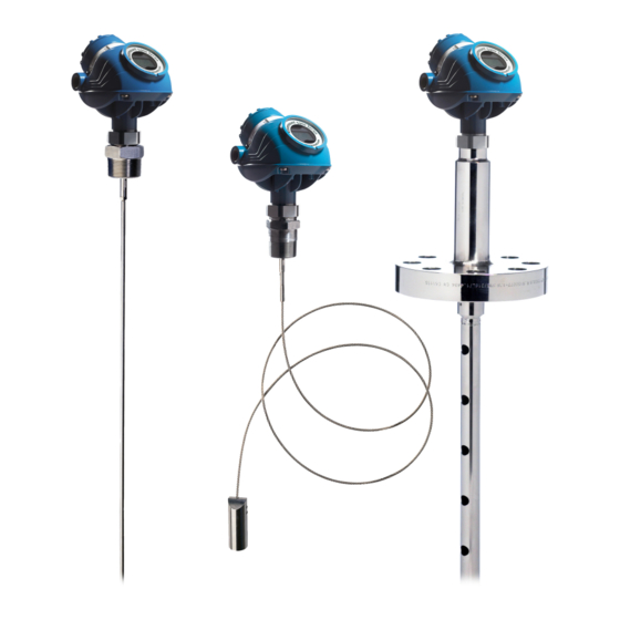
Настройка уровнемера достаточно кропотливое занятие. Существует очень много видов уровнемеров, а так же их производителей. Для их настройки используются различные программы а так же способы их подключения к ноубуку. С каждым прибором идет инструкция по настройке прибора. Но используя только инструкцию по настройке, сложно правильно настроить прибор. На данной странице предлагаю рассмотреть настройку уровнемера Rosemount5300 в том числе с разделом фаз. Как подключиться к прибору с помощью программы PACTware можно посмотреть на странице на странице «Насторйка приборов программой PACTware». На данной странице рассмотрим вариант подключения уровнемера с протоколом связи Foundation fieldbus.
- Как установить программу Radar Master.
- Как подключиться к прибору по протоколу Foundadation Fieldbas.
- Проверка и сохранение настроек уровнемера.
- Виды резервуаров.
- Как замерить уровень и раздел фаз в резервуаре электронной рулеткой.
- Как замерить уровень и раздел фаз в резервуаре механической рулеткой.
- Внесение измеренных значений уровня в программу Radar Master
- Определение уровня в резервуаре по эхосигналу уровнемера.
- Возможные причины некорректных показаний уровнемера.
Скачать программу Radar Master для настойки уровнемеров бесплатно не получиться. Данная программа поставляется на CD диске вместе с уровнемером. При желании можно купить программу на сайте разработчика. Сколько стоит, не знаю. Для получения информации необходимо отправить запрос, заполнив свои данные. При установке программы по протоколу HART у вас должен быть установлен драйвер на имеющийся у вас модем. Как установить драйвер на HART-модем можно посмотреть на странице «Настройка приборов программой PACTware». Каких либо проблем при установке программы Radar Master не возникает. Для подключения по протоколу Foundadation Fieldbas (далее FF) необходимо иметь Модем USB полевой шины Fieldbus . Например производителя Emerson. Модем поставляется вместе с программным обеспечением. Подробная инструкция по установке программы и подключения к прибору имеется в инструкции по эксплуатации.
2. Как подключиться к прибору по протоколу Foundadation Fieldbas
В инструкции по эксплуатации на модем FF имеется рисунок подключения ноутбука к прибору.

При подключении к прибору в лабораторных условиях данная схема конечно применима. Предлагаемая схема подключения в полевых условиях предполагает подключение прибора к ноутбуку в полевых условиях, что не всегда возможно. По требованиям безопасности, ноутбук при использовании во взрывоопасной зоне должен быть взрывобезопасного исполнения. Не всегда удобно носить ноутбук в «поле», особенно в непогоду, или мороз. При настройке прибора может выключиться питание ноутбука от батареи, и прибор может уйти «в ошибку». Потеряются показания прибора. Т.к. обычно для настройки прибора оперативным персоналом выделяется очень небольшой промежуток времени, то длительное отсутствие показаний может повлечь за собой нарушение технологического процесса. Для возможности настройки прибора и контроля его работы в течение длительного времени я подключаю FF-модем в кроссовом шкафу. Прежде чем производить какие либо действия с любым прибором по протоколу FF как обычно необходимо все свои действия согласовать с оперативным персоналом. Прибор обязательно должен быть выведен в «сервисный режим». Т.е. инженер АСУ ТП должен программно перевести в режим «Out of Service». При подключении в «рабочем режиме» «Auto» к прибору может произойти программный сбой, и могут потеряться показания («зависнуть») всех приборов одного «сигмента FF».

В кросовом шкафу находим провода полевой шины сигмента, к которым подключен прибор. Подключаем параллельно FF-модем. Для FF-протокола «полярность» значения не имеет. Запускаем программу Radar Master.
Для подключения к уровнемеру при запуске программы выбираем вид протокола связи Foundadation Fieldbas

Запускается программа. Открывается окно настройки уровнемера. Производим поиск приборов. В окошке «Список приборов» будет отображаться список приборов подключенных к программе приборов.

Выбираем необходимый нам прибор. Подключаем его

Заходим в меню «Общие настройки». Проверяем, переведен ли прибор в режим «Out of Service». Если блок находиться в режиме «Auto», переводим в режим «Out of Service».
3.Проверка и сохранение настроек уровнемера.
Нажимая кнопку «Прочитать» считываем настройки прибора.

Конфигурацию прибора сохраняем в отдельной папке.

Запускаем мастер настройки прибора. Кнопкой «Вперед» просматриваем и сохраняем для себя все настройки прибора.

Заходим в меню настройки резервуара. Считываем их. Данные сохраняем. Обычно все настройки я сохраняю в виде скриншотов в отдельной папке, созданной для данного уровнемера.

В данной вкладке есть меню «Условия работы». Необходимо проверить, правильно выставлен диапазон диэлектрической проницаемости среды.

4.Виды резервуаров
Самое сложное возникает с настройкой параметров резервуара. Для правильной настройки необходимо правильно провести замер базовой высоты резервуара, уровня жидкости, уровня раздела фаз. Конечно же, эти замеры не производят специалисты КИПиА. Обычно эти замеры проводит технологический персонал, с соблюдением всех мер безопасности. Но для уверенности в правильности замеров зачастую приходиться лично присутствовать при замерах. При коммерческих учетах измерение уровня в резервуаре проводят после отстоя нефти продолжительностью не менее двух часов с момента окончания заполнения. Резервуары бывают разного типа.
- РВС- резервуар вертикальный стальной со стационарной крышей без понтона;
- РВСП- резервуар вертикальный стальной со стационарной крышей с понтоном;
- РВСПК — резервуар вертикальный стальной с плавающей крышей;
Всем кому интересно более подробное устройство резервуаров могут ознакомиться с их устройством в ГОСТ 31385-2016 «РЕЗЕРВУАРЫ ВЕРТИКАЛЬНЫЕ ЦИЛИНДРИЧЕСКИЕ СТАЛЬНЫЕ ДЛЯ НЕФТИ И НЕФТЕПРОДУКТОВ». Нас интересуют данные, которые необходимо внести в уровнемер. Технология замеров уровня в резервуарах так же разная. Рассмотрим вариант измерения уровня в стальном цилиндрическом резервуаре с разделом фаз вода/нефтепродукты.

5.Как замерить уровень и раздел фаз в резервуаре электронной рулеткой
Возможно провести измерения уровня и уровня раздела фаз в резервуаре, электронной измерительной рулеткой — например «HERMetic Gtex 2000».

Электронная рулетка применяется для проведения измерений уровня в резервуарах, без контакта работника, с измеряемой средой. Рулетка имеет быстросъемное соединение с патрубком, смонтированном на измерительном фланце. При проведении измерений необходимо соблюдать все меры предосторожности прописанные в инструкции по эксплуатации. До проведения замеров рулетку необходимо заземлить.
После соединения с фланцем открывается шаровый кран, и производиться замер. При соприкосновении с поверхностью жидкости изменяется звуковой сигнал издаваемый рулеткой на более короткие сигналы. При достижении электродами рулетки уровня раздела фаз, звуковой сигнал изменяется на прерывистый.
Более подробно порядок проведения измерения электронной рулеткой можете почитать в инструкции по эксплуатации по ссылке. При измерении электронной рулеткой следует учитывать длину всех монтажных элементов до отметки базовой высоты резервуара. До начала измерения, при полностью смотанной на катушку ленте, показания измерительной рулетки уже будут 474 мм.

К этому значению необходимо прибавить значение равному Ln от ответного измерительного фланца рулетки до базовой высоты резервуара (обычно это край фланца измерительного люка). Сумма двух значений будет составлять величину Lnr. Эту величину вычитаем от показаний рулетки до уровня D1 в резервуаре и до уровня раздела фаз D2.

Получаем 2 значения. D1- дистанция от базовой высоты до уровня в резервуаре. D2- дистанция от базовой высоты до уровня раздела фаз. Вычитая эти значения от базовой высоты Lб получим значения уровня жидкости в резервуаре L1и уровень раздела фаз L2. Базовую высоту придется брать из паспорта резервуара.
Очень редко бывает так, что фланец измерительного люка и фланец, на котором размещен уровнемер, находятся на одном уровне. Для каждого патрубка на резервуаре в паспорте указывается разница по высоте между базовой высотой Lб и высотой расположения патрубка уровнемера d1 и d2.
Прибавляя значения d1 и d2 к базовой высоте резервуара мы получим значения базовой высоты для каждого уровнемера.
Останется только правильно внести все значения в соответствующие проведенным замерам, уровнемеры. В результате вычислений уровнемеры должны показывать реальные значения уровня в резервуаре. При этом разность показаний между уровнемерами должна совпадать с разностью измеренных значений рулеткой между уровнем в резервуаре L1 и уровнем раздела фаз L2. Данное значение отображается так же на мониторе АРМ оператора.

Очень удобно проводить замеры электронной рулеткой. Но иногда провести замеры электронной рулеткой не получается. На фотографии ниже вы увидите, что электроды рулетки расположенные в нижней части лота забиваются нефтепродуктами. Раздел фаз при этом определить не представляется возможным. В этом случае приходиться пользоваться обычной механической рулеткой с лотом.

6.Как замерить уровень и раздел фаз в резервуаре механической рулеткой.
При проведении замера уровня и раздела фаз в резервуаре с помощью обычной измерительной рулетки с лотом, приходиться замеры производить по другой схеме.
Рулетка с лотом так же позволяет определить раздел фаз в резервуаре. Для этого необходима водочувствительная индикаторная паста для нефтепродуктов. На участок стальной ленты, где предположительно должен находиться уровень раздела фаз наносится водочувствительная паста. Длина участка с нанесенной пастой может быть и 1 и 2 метра. Водочувствительную пасту наносят тонким слоем (0,2¸0,3) мм на поверхность лота полосками с двух противоположных сторон.
В замерных люках резервуаров, имеется специальная направляющая канавка для стальной лены рулетки. Опускать и поднимать ленту следует по этой направляющей канавке. Лот очень осторожно необходимо опустить на дно резервуара. При этом показания рулетки должны совпадать с базовой высотой в паспорте резервуара. При отклонении от паспортных данных базовой высоты, следует понимать, что в резервуаре имеются донные отложения. Разница между паспортным значением и измеренным значением будет уровнем донных отложений. При различных значениях измеренной рулеткой и паспортными данными, значений базовой высоты резервуара, необходимо ориентироваться на дистанцию от базовой высоты резервуара до уровня нефтепродуктов и уровня раздела фаз. При отсутствии донных отложений можно замерить уровень и раздел фаз прямым методом.

Поднимают ленту рулетки строго вверх, без смещения в сторону, чтобы избежать искажения линии смачивания на ленте рулетки. На ленте рулетки после появления смоченной части определяют высоту уровня жидкости в резервуаре либо дистанцию до уровня нефтепродуктов от базовой высоты.
При дальнейшем подъеме измерительной лены, необходио определить уровень раздела фаз. Нанесенная на ленте водочувствительная паста, изменит свой цвет, на уровне раздела фаз нефть/ вода. Определяем уровень воды в резервуаре, или дистанцию до уровня раздела фаз от базовой высоты. Измерение уровня в резервуаре проводят дважды. Если результаты измерений отличаются на 1 мм, то в качестве результата измерения принимается их среднее значение. Если полученное расхождение измерений более 1 мм, измерения повторяют еще дважды и берут среднее по трем наиболее близким измерениям.
При проведении замеров, необходимо соблюдать требования техники безопасности.
Останется только правильно внести измеренные показания, в данные резервуара в программе Radar Master уровнемера.

В инструкции по эксплуатации на уровнемер описано все подробно. При настройке уровнемера, инструкция по настройке у вас должна быть под рукой. Либо как минимум вы должны ее прочитать хотя бы один раз.
После внесения данных в настройки уровнемера с помощью программы Radar Master иногда могут не соответствовать показания уровнемера измеренным данным. В этом случае необходимо будет выяснить причину отклонения показаний уровнемера.
7. Внесение измеренных значений уровня в программу Radar Master
Останется только правильно внести измеренные показания, в данные резервуара в программе Radar Master уровнемера.

В инструкции по эксплуатации на уровнемер описано все подробно. При настройке уровнемера, инструкция по настройке у вас должна быть под рукой. Либо как минимум вы должны ее прочитать хотя бы один раз.
8. Определение уровня в резервуаре по эхосигналу уровнемера.
После внесения данных в настройки уровнемера с помощью программы Radar Master иногда могут не соответствовать показания уровнемера измеренным данным. В этом случае необходимо будет выяснить причину отклонения показаний уровнемера.
Рассмотрим на примере резервуара пластовой воды приведенного выше.
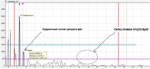
При измерении уровня взлива в резервуаре, показания уровнемера совпадают с измеренным рулеткой значением. Показания же уровнемера раздела фаз не соответствуют измеренному значению. Для выяснения причины необходимо зайти в меню «Эхосигнал». В данном меню отображается кривая эхосигнала.

Для того, что бы настроить уровнемер, нужно понять, что такое кривая эхосигнала. Попытаюсь объяснить очень примитивно. От передатчика по волноводу или по воздуху (в зависимости от излучателя) отправляется сигнал. Этот сигнал начинает отражаться от всех имеющихся на пути препятствий. Основным параметром при построении кривой, является диэлектрическая проницаемость среды. В зависимости от изменения диэлектрической проницаемости среды изменяется и величина отраженного сигнала. В итоге мы получаем кривую эхосигнала с различной амплитудой. Программа уровнемера производит вычисление уровня в резервуаре, в зависимости от внесенных в уровнемер данных и от отраженного эхосигнала. Эта программа у каждого производителя является собственной разработкой. Поэтому у различных производителей могут быть разные параметры, которые необходимо внести в программу настройки уровнемера. Но принцип отражения кривой эхосигнала практически одинаковый для всех производителей и для различных излучателей.
Поняв один раз, что отражается на кривой эхосигнала, можно всегда представить, что происходит в резервуаре (емкости). Сигнал исходит из верхней точки отсчета — Upper Reference Point. Первым препятствием для эхосигнала конечно же будет сам фланец и соединения преобразователя с зондом. Величина отраженного от фланца и соединений сигнала большая. Так же помехи для измерения создает сам патрубок, на котором смонтирован уровнемер. Поэтому отраженный от фланца сигнал отсекается программно — Distance Offset . Этот сигнал уже не учитывается при вычислении уровня. Далее следует отраженный от поверхности жидкости отраженный сигнал — Поверхность. Его амплитуда будет самая большая. Так как среда при переходе из слоя нефти в слой воды не однородная, можно увидеть на кривой эхосигнала несколько различных отраженных сигналов помех. Но в области перехода фазы нефти в фазу воды будет самый высокий отраженный сигнал – Раздел фаз. Далее на кривой эхосигнала отображаются различные сигналы помехи. Это могут быть помехи от измеряемой среды – неоднородность заполняемой в резервуар жидкости, различные налипания на зонд. Так же это могут быть помехи создаваемые самим измерительным зондом. Это могут быть повреждения тросового зонда, перемычки на двойном жестком или коаксиальном зонде и т.д.

Для понимания вида помех, вносимых самим зондом необходимо демонтировать уровнемер, хорошо промыть, почистить волновод. При подключении к уровнемеру программой Radar Master можно увидеть все сигналы помех волновода. Ниже представлена кривая эхосигнала чистого тросового волновода длиной 12350 мм. Помехи имеются. Сигнал помех не превышает значения 500 mV. Но эти помехи, говорят о том, что тросовый волновод имеет повреждения. В местах повреждений может скапливаться различные отложения. Это могут быть как нефтепродукты, так и различные солевые отложения.

Сигнал помех может значительно вырасти, и уровнемер будет искажать показания. Поэтому с волноводами надо обращаться очень бережно, не повредить их.
9. Возможные причины некорректных показаний уровнемера.
Иногда возникают ситуации, когда сигнал помех вносимых измеряемой средой, гораздо больше сигнала рздела фаз. Рассмотрим такой пример.
На резервуаре смонтированы два уровнемера. Первый уровнемер измеряет уровень взлива. Уровнемер без функции измерения раздела фаз. Он прекрасно работает. Его показания совпадают с измеренным рулеткой уровнем.

На этом же резервуаре смонтирован второй уровнемер с функцией измерения раздела фаз.

Показания уровня раздела фаз не соответствуют измеренному значению. Согласно проведенным измерениям уровень раздела фаз вода/нефть находиться в районе дистанции D2 около 5,5метра. В промежутке дистанции 9…10 метров имеется сигнал помехи большой величины. Такой же сигнал помехи можно увидеть и на первом уровнемере. Никакими рекомендованными в инструкции по настройке уровнемера, способами, отсечь данный сигнал помехи не получилось. Была ли эта помеха от внутренних конструкций резервуара, так же не представилось возможным. На данный резервуар не было паспорта.
Этот уровнемер временно был смонтирован на фланец измерительного патрубка.
Сигнал помехи на кривой эхосигнала отсутствует. Уровень раздела фаз уровнемер показывает корректно. Было принято решение смонтировать уровнемер на замерном патрубке. Вопрос некорректного показания уровня раздела фаз был решен.
Зачастую, к неправильным показаниям уровнемера приводит нарушение оперативным персоналом технологического режима. Например появление раздела фаз в емкости, где раздела фаз быть не должно.
Например, емкость для сбора серной кислоты. Используется бесконтактный радарный уровнемер. При нарушении технологического режима в емкость попадает алкилат. Появляется раздел фаз. В принципе уровнемеру должно быть все равно. Он должен показывать общий уровень. Но чем больше алкилата на поверхности серной кислоты, тем меньше уровня в емкости показывает уровнемер. Никакие попытки настроить программно правильность показаний уровнемера не дали результата. Рекомендации производителя были заменить уровнемер, на другой, с функцией раздела фаз. Так как конечно никто не купит новый уровнемер, оперативному персоналу приходилось соблюдать технологический режим. Уровнемер стал работать корректно.
Настройка уровнемеров, работающих с программой PactWare производится аналогично. Подключение уровнемеров программой PactWare описана на странице «Настройка приборов программой PactWare«.
Пишите в форуме. Делитесь опытом как решались проблемы с уровнемерами.
-
Contents
-
Table of Contents
-
Troubleshooting
-
Bookmarks
Quick Links
Reference Manual
00809-0100-4530, Rev DD
May 2016
™
Rosemount
5300 Series
Superior Performance Guided Wave Radar
Related Manuals for Rosemount 5300 Series
Summary of Contents for Rosemount 5300 Series
-
Page 1
Reference Manual 00809-0100-4530, Rev DD May 2016 ™ Rosemount 5300 Series Superior Performance Guided Wave Radar… -
Page 3: Table Of Contents
Reference Manual Introduction 00809-0100-4530, Rev DD May 2016 Contents 1Section 1: Introduction Using this manual …………1 Product recycling/disposal .
-
Page 4
Reference Manual Contents 00809-0100-4530, Rev DD May 2016 3.2.11 Installation and configuration considerations for ESD systems..34 Mounting …………35 3.3.1 Flange connection . -
Page 5
Basic configuration using a Field Communicator ……95 Basic configuration using Rosemount Radar Master ….. . .98 5.6.1… -
Page 6
7.3.1 Using Rosemount Radar Master ……. . . 153 7.3.2 Using the echo curve analyzer with a Field Communicator . -
Page 7
Reference Manual Introduction 00809-0100-4530, Rev DD May 2016 7.22.4 Measurement status ……… . . 188 7.22.5 Interface status. -
Page 8
Reference Manual Contents 00809-0100-4530, Rev DD May 2016 A.1.9 Ambient temperature ……… . 221 A.1.10Storage temperature. -
Page 9
Reference Manual Introduction 00809-0100-4530, Rev DD May 2016 B.4.4 Brazilian certifications ……… . 289 B.4.5 Chinese certifications . -
Page 10
Configure the AI Block ……….372 ® ® JAppendix J: Rosemount 5300 Series with HART to Modbus Converter Safety messages . -
Page 11
Troubleshooting ……….. . 407 J.13 HMC firmware upgrade in Rosemount Radar Master ….408 J.14 Specifications . -
Page 12
Reference Manual Contents 00809-0100-4530, Rev DD May 2016 Contents… -
Page 13
Title Page 00809-0100-4530, Rev DD May 2016 ™ Rosemount 5300 Series Guided Wave Radar Level and Interface Transmitters NOTICE Read this manual before working with the product. For personal and system safety, and for optimum product performance, make sure you thoroughly understand the contents before installing, using, or maintaining this product. -
Page 14
High voltage that may be present on leads could cause electrical shock. Avoid contact with leads and terminals. Make sure the main power to the Rosemount 5300 Transmitter is off and the lines to any other external power source are disconnected or not powered while wiring the gauge. -
Page 15: Using This Manual
Section 5: Configuration provides instructions on configuration of the transmitter using the ™ Field Communicator, the Rosemount Radar Master software, AMS Device Manager, and ™ DeltaV . Information on software functions and configuration parameters are also included.
-
Page 16: Product Recycling/Disposal
Appendix I: Analog-Input Block describes the operation and parameters of the analog input transducer block. Appendix J: Rosemount 5300 Series with HART® to Modbus® Converter describes the operation of the HART to Modbus Converter (HMC). Product recycling/disposal Recycling of equipment and packaging should be taken into consideration and disposed of in accordance with local and national legislation/regulations.
-
Page 17
Reference Manual Transmitter Overview 00809-0100-4530, Rev DD May 2016 Section 2 Transmitter Overview Theory of operation …………page 4 Applications . -
Page 18: Theory Of Operation
Theory of operation ™ The Rosemount 5300 Series Radar Transmitter is a smart, two-wire continuous level transmitter based on Time Domain Reflectometry (TDR) principles. Low power nano-sec- ond-pulses are guided along an immersed probe. When a pulse reaches the surface, part of…
-
Page 19: Applications
00809-0100-4530, Rev DD May 2016 Applications The Rosemount 5300 Series Radar Transmitter series is suited for aggregate (total) level measurements on most liquids, semi-liquids, solids, and liquid/liquid interfaces. Guided microwave technology offers the highest reliability and precision to ensure measurements are virtually unaffected by temperature, pressure, vapor gas mixtures, density, turbulence, bubbling/boiling, low level, varying dielectric media, pH, and viscosity.
-
Page 20
The Rosemount 5302 measures both level and interface level in a separator tank. Water The Rosemount 5300 Series is a good choice for underground tanks. It is installed on the top of the tank with the radar pulse concentrated near the probe. It… -
Page 21
It measures independently of dust, angled surfaces etc. The Rosemount 5300 Series with Dynamic Vapor Compensation will automatically compensate for dielectric changes in high pressure steam applications and maintain the level accuracy. -
Page 22: Components Of The Transmitter
May 2016 Components of the transmitter The Rosemount 5300 Series Radar Transmitter has an aluminum or stainless steel (SST) transmitter housing containing advanced electronics and software for signal processing. SST housing is preferred for harsh environment applications, such as off-shore platforms or other locations where the housing can be exposed to corrodents, such as salt solutions and caustics.
-
Page 23
Reference Manual Transmitter Overview 00809-0100-4530, Rev DD May 2016 Remote housing allows for the transmitter head to be mounted separately from the probe. Figure 2-4. Remote Housing Components A. Dual compartment housing B. Cable remote connection C. U-bolt D. Bracket E. -
Page 24: System Architecture
With the HART protocol multidrop configuration is possible. In this case, communication is restricted to digital, since current is fixed to the 4 mA minimum value. The transmitter can be connected to a Rosemount 751 Field Signal Indicator, or it can be equipped with an integral display.
-
Page 25
A. Rosemount 5300 F. PC 5300 Setup in Rosemount Radar Master B. Power G. Control System C. 475 Field Communicator H. RS-232/RS-485 Converter D. Modbus, Levelmaster Emulation/RS-485 I. PC 5300 Setup in Rosemount Radar Master via Tunneling E. HART modem Transmitter Overview… -
Page 26: Probe Selection Guide
Reference Manual Transmitter Overview 00809-0100-4530, Rev DD May 2016 Probe selection guide The following guidelines should be used to choose the appropriate probe for the Rosemount 5300 Series Transmitter: Rigid single Flexible Coaxial Rigid twin Flexible twin lead, single lead…
-
Page 27
Reference Manual Transmitter Overview 00809-0100-4530, Rev DD May 2016 Rigid single Flexible Coaxial Rigid twin Flexible twin lead, single lead lead lead segmented rigid single lead G = Good NR = Not Recommended AD = Application Dependent (consult your local Emerson Process Management representative) Turbulence… -
Page 28: Measuring Range
Reference Manual Transmitter Overview 00809-0100-4530, Rev DD May 2016 Measuring range The measuring range depends on probe type, dielectric constant of the product and installation environment, and is limited by the Blind Zones at the very top and bottom of the probe.
-
Page 29: Process Characteristics
May 2016 Process characteristics The Rosemount 5300 Series has high sensitivity because of its advanced signal processing and high signal to noise ratio. This makes it able to handle various disturbances, however, the following circumstances should be considered before mounting the transmitter.
-
Page 30: Interface
2.7.6 Interface Rosemount 5302 is the ideal choice for measuring the level of oil, and the interface of oil and water, or other liquids with significant dielectric differences. Rosemount 5301 can also be used for interface measurement in applications where the probe is fully submerged in the liquid.
-
Page 31: Vessel Characteristics
2.8.1 Heating coils, agitators Because the radar signal is transmitted along a probe, the Rosemount 5300 Radar Transmitter is generally not affected by objects in the tank. Avoid physical contact with metallic objects when twin lead or single lead probes are used.
-
Page 32: Installation Procedure
Reference Manual Transmitter Overview 00809-0100-4530, Rev DD May 2016 Installation procedure Follow these steps for proper installation: Review mounting considerations (see page Mount the transmitter (see page Wire the transmitter (see Section 4: Electrical Installation) Make sure covers and cable/conduit connections are tight Power up the transmitter…
-
Page 33: Safety Messages
Reference Manual Mechanical Installation 00809-0100-4530, Rev DD May 2016 Section 3 Mechanical Installation Safety messages …………page 19 Mounting considerations .
-
Page 34: Mounting Considerations
Mounting. 3.2.1 Process connection The Rosemount 5300 Series has a threaded connection for easy mounting on a tank roof. It can also be mounted on a nozzle by using different flanges. Threaded connection Figure 3-1. Mounting on Tank Roof Using Threaded Connection…
-
Page 35
Reference Manual Mechanical Installation 00809-0100-4530, Rev DD May 2016 Flange connection on nozzles Figure 3-2. Mounting in Nozzles Avoid nozzles with reducer Hold Off Distance/UNZ (unless using coaxial probe). Make sure the nozzle does not extend into the tank. The transmitter can be mounted in nozzles by using an appropriate flange. The nozzle sizes given in Table 3-1 show the recommended dimensions. -
Page 36: Installation In Non-Metallic Tanks And Open-Air Applications
Reference Manual Mechanical Installation 00809-0100-4530, Rev DD May 2016 A long stud — 9.8 in. (250 mm) — is recommended for single flexible probes in a tall nozzle. Figure 3-3. A Single Flexible Probe with a Long Stud Long Stud (9.8 in./250 mm) Note For single lead probes, avoid 10-in.
-
Page 37: Installation In Concrete Silos
Reference Manual Mechanical Installation 00809-0100-4530, Rev DD May 2016 For clean liquids, use a coaxial probe to reduce effect of potential electrical disturbances. Figure 3-5. Coaxial Probe in an Open-Air Application For optimal single lead probe performance in non-metallic tanks, the probe must be mounted with a metal flange, or screwed in to a metal sheet (d >…
-
Page 38: Considerations For Solid Applications
Tensile strength is minimum 6519 lb (29 kN) Collapse load is maximum 7868 lb (35 kN) Keep the following in mind when planning installation of the Rosemount 5300 in solid applications: There might be considerable down-pull forces on silo roofs caused by the media, so …
-
Page 39: Mounting In Chamber/Still Pipe
Reference Manual Mechanical Installation 00809-0100-4530, Rev DD May 2016 Table 3-2. Pulling Force on Probe Installed in Tanks with Different Products Tensile load for 0.16 in. (4 mm) Tensile load for 0.24 in. (6 mm) flexible single lead probe, lb (kN) flexible single lead probe, lb (kN) Material Probe length 49 ft (15 m)
-
Page 40
The single probe creates a virtual coaxial probe with the chamber as the outer tube. The extra gain provided by the twin and coaxial probes is not necessary; the electronics in the Rosemount 5300 Series is very sensitive and is not a limiting factor. -
Page 41
Reference Manual Mechanical Installation 00809-0100-4530, Rev DD May 2016 The probe must not touch the chamber wall, should extend the full height of the chamber, but not touch the bottom of the chamber. Probe type selection depends on probe length: Less than 20 ft (6 m): Rigid single probe is recommended. -
Page 42
00809-0100-4530, Rev DD May 2016 When mounting in a Rosemount 9901 chamber, see Table 3-4 for information on probe length determination. Table 3-4. Probe Length Determination for Rosemount 9901 Chambers Probe length Chamber Side-and-side chamber Side-and-bottom chamber Rosemount 9901 B + 19 in. (480 mm) B + 4 in. -
Page 43: Replacing A Displacer In An Existing Displacer Chamber
Considerations when changing to Rosemount 5300 When changing from a displacer to a Rosemount 5300 Series Transmitter, make sure to correctly match the Rosemount 5300 Series flange choice and probe length to the chamber. Both standard ANSI and EN (DIN), as well as proprietary chamber flanges are available.
-
Page 44: Free Space
Reference Manual Mechanical Installation 00809-0100-4530, Rev DD May 2016 3.2.7 Free space For easy access to the transmitter, make sure it is mounted with sufficient service space. For maximum measurement performance, the transmitter should not be mounted close to the tank wall or near other objects in the tank.
-
Page 45: Recommended Mounting Position For Liquids
Reference Manual Mechanical Installation 00809-0100-4530, Rev DD May 2016 3.2.8 Recommended mounting position for liquids Tank conditions are recommended to be carefully considered when finding the appropriate mounting position for the transmitter. The transmitter should be mounted so the influence of disturbing objects is reduced to a minimum.
-
Page 46: Recommended Mounting For Solids
Reference Manual Mechanical Installation 00809-0100-4530, Rev DD May 2016 3.2.9 Recommended mounting for solids Figure 3-15. Recommended Mounting for Solids Consider the following guidelines when mounting the transmitter: Do not mount near inlet pipes in order to avoid product filling on the probe. …
-
Page 47: Insulated Tanks
May 2016 3.2.10 Insulated tanks When the Rosemount 5300 is installed in high temperature applications, consider the maximum ambient temperature. Tank insulation should not exceed 4 in. (10 cm) above the top of the process connection. Figure 3-16. Tank Insulation A.
-
Page 48: Installation And Configuration Considerations For Esd Systems
Reference Manual Mechanical Installation 00809-0100-4530, Rev DD May 2016 3.2.11 Installation and configuration considerations for ESD systems Figure 3-18 shows a common example of an Emergency Shutdown (ESD) system in a separator. High-high and low-low transmitters act as redundant safeguards. They will trigger emergency shutdowns or redirect flow of the application.
-
Page 49: Mounting
Reference Manual Mechanical Installation 00809-0100-4530, Rev DD May 2016 Low-low unit The distance from flange to upper inlet must be at least 20 in. (500 mm). If this requirement is not met, a spool piece can be added. When the requirement of 20 in. (500 mm) is met, an Upper Null Zone (UNZ) of 14 in.
-
Page 50: Flange Connection
Reference Manual Mechanical Installation 00809-0100-4530, Rev DD May 2016 3.3.1 Flange connection Figure 3-21. Tank Connection with Flange A. Transmitter head B. Nut C. Bolts D. Flange E. Probe F. Gasket G. Tank flange H. PTFE covered probe with protective plate The transmitter is delivered with head, flange, and probe assembled into one unit.
-
Page 51
Reference Manual Mechanical Installation 00809-0100-4530, Rev DD May 2016 Figure 3-22. Tank Connection with Loose Flange (“Plate Design”) A.Flange nut B.Bolts C.Probe D.Tank flange E.Transmitter head F. Nut G.Flange H.Gasket Transmitters delivered with alloy probes featuring plate design are mounted as described below: Place a gasket on top of the tank flange. -
Page 52: Threaded Connection
Reference Manual Mechanical Installation 00809-0100-4530, Rev DD May 2016 3.3.2 Threaded connection Figure 3-23. Threaded Tank Connection A.Tank connection B.Probe C.Nut D.Sealant on threads or gasket (for BSP/G threads) For tank connections with BSP/G threads, place a gasket on top of the tank flange, or use a sealant on the threads of the tank connection.
-
Page 53: Tri Clamp Connection
Reference Manual Mechanical Installation 00809-0100-4530, Rev DD May 2016 3.3.3 Tri Clamp connection Figure 3-24. Tri Clamp Tank Connection A. Nut B.Probe C.Gasket D.Tank E.Transmitter head F. Tri Clamp G.Clamp Place a gasket on top of the tank flange. Lower the transmitter and probe into the tank. Fasten the Tri Clamp to the tank with a clamp.
-
Page 54: Bracket Mounting
Reference Manual Mechanical Installation 00809-0100-4530, Rev DD May 2016 3.3.4 Bracket mounting On pipe Mount the bracket to the pipe. Put the two U-bolts through the holes of the bracket. Vertical pipe Horizontal pipe b. Put the clamping brackets on the U-bolts and around the pipe. Use the supplied nuts to fasten the bracket to the pipe.
-
Page 55
Reference Manual Mechanical Installation 00809-0100-4530, Rev DD May 2016 Mount the transmitter with probe to the bracket. On wall Mount the bracket directly to the wall with screws suitable for the purpose. Mount the transmitter with probe to the bracket. Mechanical Installation… -
Page 56: Shortening The Probe
Reference Manual Mechanical Installation 00809-0100-4530, Rev DD May 2016 3.3.5 Shortening the probe Note HTHP coaxial and PTFE probes must not be shortened. Flexible twin/single lead Minimum: 1.6 in./40 mm Spacer Allen screws Mark off the required probe length. Add at least 1.6 in. (40 mm) to the required probe length to be inserted into the weight.
-
Page 57
Reference Manual Mechanical Installation 00809-0100-4530, Rev DD May 2016 Rigid single lead Cut the single lead probe to the desired length. The minimum probe length is 15.7 in. (400 mm). If a centering disc is used, follow the instructions on page Update the transmitter configuration to the new probe length, see “Tank and… -
Page 58
Reference Manual Mechanical Installation 00809-0100-4530, Rev DD May 2016 Coaxial Note The HTHP coaxial probe must not be cut in field. To cut a coaxial probe: Insert the centering piece. The centering piece is delivered from factory and should be used to prevent the spacers centering the rod from coming loose. -
Page 59: Using A Segmented Probe
Reference Manual Mechanical Installation 00809-0100-4530, Rev DD May 2016 3.3.6 Using a segmented probe Figure 3-26. Segmented Probe Parts 15.2 (385) 31.5 (800) Dimensions are in inches (mm). A. Safety ring B. Screw C. Top segment D. Split pin E. PTFE washer (optional) F.
-
Page 60
Reference Manual Mechanical Installation 00809-0100-4530, Rev DD May 2016 Verify probe length Segmented probe ordered with model code 4S Before installation, verify the probe length (L) on the label. If the probe length needs to be adjusted, see “Adjusting the probe length” on page Probe length Probe segments box Segmented probe ordered as spare part kit… -
Page 61
Reference Manual Mechanical Installation 00809-0100-4530, Rev DD May 2016 Pre-assemble the safety ring. Optional: If ordered, mount the centering disc on the bottom segment of the probe. Bottom Segment Insert the support tool. Bottom Segment Mechanical Installation… -
Page 62
Reference Manual Mechanical Installation 00809-0100-4530, Rev DD May 2016 Optional: If ordered, mount the centering disc. Note Maximum five pcs/probe Minimum two segments between each centering disc Mount a middle segment. Hand tighten Mechanical Installation… -
Page 63
Reference Manual Mechanical Installation 00809-0100-4530, Rev DD May 2016 Secure the split pin. Insert the second support tool. Mechanical Installation… -
Page 64
Reference Manual Mechanical Installation 00809-0100-4530, Rev DD May 2016 Remove the first support tool and lower the probe into the tank. Repeat steps until all segments are mounted. Make sure to finish with the top segment of the probe. Seal and protect threads. Only for NPT threaded tank connection. -
Page 65
Reference Manual Mechanical Installation 00809-0100-4530, Rev DD May 2016 Attach the probe to the device. Flange / Tri Clamp Threaded Sealant on threads (NPT) Gasket (BSP/G) Gasket Note For safety reasons, at least two people are needed when mounting the device. Make sure to hold the device above the tank. -
Page 66
Reference Manual Mechanical Installation 00809-0100-4530, Rev DD May 2016 Remove the support tool. Mount the device on the tank. Threaded Flange Tri Clamp Rotate the housing to the desired direction. Tighten the nut. The torque must be 30 Lbft (40 Nm). Connect the wiring. -
Page 67
Reference Manual Mechanical Installation 00809-0100-4530, Rev DD May 2016 Adjusting the probe length Determine L, the desired probe length. L, desired probe length: Determine n, the number of middle segments needed for the desired probe length. Table 3-7 Table 3-8 on page n, number of middle segments: Calculate Y, the length of the bottom segment. -
Page 68
Reference Manual Mechanical Installation 00809-0100-4530, Rev DD May 2016 Mark where to cut the bottom segment. Cut the bottom segment at the mark. Note Make sure the bottom segment is fixed while cutting. Optional: If a bottom centering disc is ordered, then drill two holes on the bottom segment using the drilling fixture. -
Page 69
11 pcs Y = L — 362.2 Y = L — 9200 Maximum probe length is 32 ft 9 in. (10 m) for the Rosemount 5300 Series. Table 3-8. Determination of Probe Segments for HTHP/HP/C Seal Desired probe length (L) -
Page 70: Anchoring
Reference Manual Mechanical Installation 00809-0100-4530, Rev DD May 2016 3.3.7 Anchoring In turbulent tanks, it may be necessary to fix the probe. Depending on the probe type, different methods can be used to guide the probe to the tank bottom. This may be needed to prevent the probe from hitting the tank wall or other objects in the tank, as well as preventing a probe from breaking.
-
Page 71
Reference Manual Mechanical Installation 00809-0100-4530, Rev DD May 2016 Coaxial probe The coaxial probe can be guided by a tube welded on the tank bottom. Tubes are customer supplied. Make sure that the probe can move freely in order to handle thermal expansion. The measurement accuracy will be reduced close to the tube opening. -
Page 72
Reference Manual Mechanical Installation 00809-0100-4530, Rev DD May 2016 Solid applications Pull the probe rope through a suitable anchoring point, e.g. a welded eye and fasten it with two clamps. It is 1cm/m recommended the probe is slack in order to prevent high tensile loads. -
Page 73: Mounting A Centering Disc For Pipe Installations
Table 3-10 shows which centering disc diameter to choose for a particular pipe and Table 3-11 shows which centering disc diameter to choose for a Rosemount 9901 Chamber. Table 3-10. Centering Disc Size Recommendation for Different Pipe Schedules Pipe size…
-
Page 74
Reference Manual Mechanical Installation 00809-0100-4530, Rev DD May 2016 Table 3-11. Centering Disc Size Recommendations for Rosemount 9901 Chambers Chamber size Chamber rating Centering disc Up to Class 600/PN 100 3 in. 3 in. Class 900, 1500/PN160, 250 2 in. -
Page 75
Reference Manual Mechanical Installation 00809-0100-4530, Rev DD May 2016 Mounting a centering disc on flexible single probes Note When using centering discs made of PTFE, note that the maximum temperature is 392 °F (200 °C). Figure 3-29. Centering Disc at the End of the Weight A. -
Page 76
Reference Manual Mechanical Installation 00809-0100-4530, Rev DD May 2016 Mounting a centering disc on rigid single probes Note Centering discs shall not be used with PTFE covered probes. Rigid single lead probe (8 mm) Drill one hole using the drilling fixture (included in your shipment). A. -
Page 77
Reference Manual Mechanical Installation 00809-0100-4530, Rev DD May 2016 Secure the split pin. Rigid single lead/segmented rigid single lead probe (13 mm) Drill two holes using the drilling fixture (included in your shipment). A. Drilling fixture B. Probe Mount the bushings and centering disc at the probe end. A. -
Page 78
Reference Manual Mechanical Installation 00809-0100-4530, Rev DD May 2016 Adjust distance by shifting hole for split pin in lower bushing. 0.16 in. (4 mm) 0.08 in. (2 mm) Insert the split pins through the bushings and the probe. Secure the split pins. Mechanical Installation… -
Page 79: Safety Messages
Reference Manual Electrical Installation 00809-0100-4530, Rev DD May 2016 Section 4 Electrical Installation Safety messages …………page 65 Cable/conduit entries .
-
Page 80: Cable/Conduit Entries
High voltage that may be present on leads could cause electrical shock. Avoid contact with leads and terminals. ™ Make sure the main power to the Rosemount 5300 Transmitter is off and the lines to any other external power source are disconnected or not powered while wiring the gauge.
-
Page 81: Cable Selection
Cable selection Use shielded twisted pair wiring for the Rosemount 5300 Series to comply with EMC regulations. The cables must be suitable for the supply voltage and approved for use in hazardous areas, where applicable. For instance, in the U.S., explosion-proof conduits must be used in the vicinity of the vessel.
-
Page 82: Connecting The Transmitter
Reference Manual Electrical Installation 00809-0100-4530, Rev DD May 2016 Connecting the transmitter Make sure the power supply is switched off. Remove the terminal block cover. Remove the plastic plugs. Pull the cable through the cable gland/conduit. Adapters are required if M20 glands are used. To connect the wires, see the illustrations on the following pages.
-
Page 83
Reference Manual Electrical Installation 00809-0100-4530, Rev DD May 2016 Use the enclosed metal plug to seal any unused port. Note Apply PTFE tape or other sealant to the threads. Tighten the cable gland. Note Apply PTFE tape or other sealant to the threads. Note Make sure to arrange the wiring with a drip loop. -
Page 84: Hart
Connect the power supply. ® HART 4.7.1 Power requirements Terminals in the transmitter housing provide connections for signal cables. The Rosemount 5300 Transmitter is loop-powered and operates with the following power supplies: Hazardous approval Current 3.75 mA 21.75 mA…
-
Page 85: Maximum Loop Resistance
Reference Manual Electrical Installation 00809-0100-4530, Rev DD May 2016 4.7.2 Maximum loop resistance The maximum current loop resistance (see Figure 4-5 Figure 4-6) is given by the following diagrams: Figure 4-2. Explosion-Proof / Flameproof Installations Operating External power region supply voltage Note This diagram is only valid if the load resistance is at the + side and if the — side is grounded, otherwise the maximum load resistance is limited to 435 .
-
Page 86: Non-Intrinsically Safe Output
Figure 4-5. Note Make sure the power supply is off when connecting the transmitter. Figure 4-5. Wiring Diagram for Non-Intrinsically Safe Installations (HART) Field Rosemount 5300 Series Communicator Radar Transmitter ™ Suite HART modem Load resistance 250 …
-
Page 87: Intrinsically Safe Output
Make sure the instruments in the loop are installed in accordance with intrinsically safe field wiring practices and system control drawings when applicable. Figure 4-6. Wiring Diagram for Intrinsically Safe Installations (HART) Field Rosemount 5300 Series Communicator Radar Transmitter AMS Suite…
-
Page 88: Foundation
™ Fieldbus OUNDATION 4.8.1 Power requirements Terminals in the transmitter housing provide connections for signal cables. The Rosemount 5300 Transmitter is powered over F Fieldbus with standard fieldbus power OUNDATION supplies. The transmitter operates with the following power supplies: Approval type…
-
Page 89: Foundation Fieldbus
Reference Manual Electrical Installation 00809-0100-4530, Rev DD May 2016 Connecting fieldbus devices Figure 4-7. Rosemount 5300 Radar Transmitter Field Wiring 6234 ft (1900 m) maximum (depending upon cable characteristics) Integrated power conditioner and filter Terminators Fieldbus segment (Trunk) Power supply…
-
Page 90: Non-Intrinsically Safe Output
Figure 4-8. Note Make sure that the power supply is off when connecting the transmitter. Figure 4-8. Wiring for Non-Intrinsically Safe Power Supply (F Fieldbus) OUNDATION Rosemount 5300 Series Radar Transmitter = 250 V Power supply Fieldbus modem Field Communicator…
-
Page 91: Intrinsically Safe Output
Make sure the instruments in the loop are installed in accordance with intrinsically safe field wiring practices. Figure 4-9. Wiring Diagram for Intrinsically Safe Power Supply (F Fieldbus) OUNDATION Rosemount 5300 Series Radar Transmitter Approved IS barrier Power supply Fieldbus modem…
-
Page 92: Optional Devices
Configure channels 1, 2, and 3 to reflect the units as well as upper range values and lower range values for your secondary, tertiary and fourth variables (variable assignment is configured in the Rosemount 5300). It is also possible to enable or disable a channel from this menu. See “Tri-Loop™…
-
Page 93: 751 Field Signal Indicator
Reference Manual Electrical Installation 00809-0100-4530, Rev DD May 2016 4.9.2 751 Field Signal Indicator Figure 4-11. Wiring Diagram for a Rosemount 5300 Transmitter with 751 Field Signal Indicator Rosemount 5300 Series Radar Transmitter Model 751 Field Signal Indicator Power supply…
-
Page 94
Reference Manual Electrical Installation 00809-0100-4530, Rev DD May 2016 Electrical Installation… -
Page 95: Safety Messages
Basic configuration using a Field Communicator …….page 95 Basic configuration using Rosemount Radar Master ……page 98 Basic configuration using AMS Suite (HART) .
-
Page 96: Overview
If the transmitter is pre-configured at the factory according to the ordering specifications in the Configuration Data Sheet, no further basic configuration is required unless tank conditions have changed. The Rosemount 5300 Series supports a set of advanced configuration options as well, which can be used to handle special tank conditions and applications.
-
Page 97: Configuration Tools
Rosemount Radar Master (RRM). Note that RRM is recommended for advanced configuration features. “Basic configuration using Rosemount Radar Master” on page 98 information on how to use RRM for configuration of the Rosemount 5300 Series Field Communicator. “Basic configuration using a Field Communicator” on page 95…
-
Page 98: Host System Integration
2F0 or later 2A2 — 2E0 Firmware version is printed on the transmitter head label, e.g. SW 2E0 or can be found in Rosemount Radar Master (select Device > Properties). Device revision is printed on the transmitter head label, e.g. HART Dev Rev 4.
-
Page 99: Set Alarm Limits
Reference Manual Configuration 00809-0100-4530, Rev DD May 2016 5.3.2 Set alarm limits The alarm limits that are set in the host system need to be adjusted for the expected maximum product level rate and configured Damping Value. When setting the high alarm limit, a safety margin (see Figure 5-1) should be subtracted from the desired high alarm limit.
-
Page 100
Reference Manual Configuration 00809-0100-4530, Rev DD May 2016 To set the alarm limits, do the following: Identify maximum product level rate for the application. Note configured Damping Value. In RRM, select Setup > Advanced, and click the Echo Tracking tab. … -
Page 101
Reference Manual Configuration 00809-0100-4530, Rev DD May 2016 Example Maximum product level rate = 100 mm/min Damping Value = 10 s The Signal Quality Metrics is turned off in this example, so the safety margin is calculated by using Table 5-2. -
Page 102: Basic Configuration Parameters
Basic configuration parameters This section describes basic configuration parameters for a Rosemount 5300 Transmitter. Basic configuration is only needed for the Rosemount 5300 Series Transmitters which are not pre-configured at the factory. Factory configuration is normally specified in the Configuration Data Sheet.
-
Page 103
Reference Manual Configuration 00809-0100-4530, Rev DD May 2016 For the different tank connections the Upper Reference Point is located at the underside of the threaded adapter or at the underside of the welded flange, as illustrated in Figure 5-5: Figure 5-5. Upper Reference Point BSP/G Flange Tri Clamp… -
Page 104: Tank Environment
Tank environment Measurement mode Normally, the measurement mode does not need to be changed. The transmitter is pre-configured according to the specified model: Table 5-4. List of Measurement Modes for Different Rosemount 5300 Models Model Measurement mode Rosemount 5301 Liquid product level …
-
Page 105: Volume Configuration
Optimize the transmitter for measurement conditions where the level changes quickly due to filling and emptying of the tank. As a default standard, a Rosemount 5300 Transmitter is able to track level changes of up to 1.5 in./s (40 mm/s). When the Rapid Level Changes check-box is marked, the transmitter can track level changes of up to 8 in./s (200 mm/s).
-
Page 106
Reference Manual Configuration 00809-0100-4530, Rev DD May 2016 Tank type You can choose one of the following options: Strap table Vertical cylinder Horizontal cylinder Vertical bullet Horizontal bullet Sphere None Strapping table Use a strapping table if a standard tank type does not provide sufficient accuracy. Use most of the strapping points in regions where the tank shape is non-linear. -
Page 107
Reference Manual Configuration 00809-0100-4530, Rev DD May 2016 Standard tank shapes Figure 5-7. Standard Tank Shapes Vertical cylinder Vertical cylinder tanks are specified by diameter, height, and volume offset. Diameter Height Horizontal cylinder Horizontal cylinders are specified by Diameter diameter, height, and volume offset. Height Vertical bullet Vertical bullet tanks are specified by… -
Page 108: Analog Output (Hart)
Reference Manual Configuration 00809-0100-4530, Rev DD May 2016 5.4.5 Analog output (HART) The output source (Primary Value), range values, and alarm mode are specified for the analog output. Figure 5-8. Example of Range Value Settings Upper Reference Point Upper Blind Zone Reduced accuracy Upper Range Value (URV) = 100% 20 mA…
-
Page 109: Basic Configuration Using A Field Communicator
High 20.5 mA 22.5 mA Basic configuration using a Field Communicator This section describes how to configure the Rosemount 5300 Series Transmitter by using a Field Communicator. The menu tree with the various configuration parameters is shown in Figure 5-11. Section “Basic configuration parameters”…
-
Page 110
Select Finish, Device Specific Setup to see if there is any additional configuration that needs to be done. Restart the transmitter. HART command: [3, 2, 1, 1]. See also “Guided setup” on page 104 for further information on configuration of the Rosemount 5300 Transmitter. Configuration… -
Page 111
Reference Manual Configuration 00809-0100-4530, Rev DD May 2016 Figure 5-11. Field Communicator Menu Tree Corresponding to Device Revision 3 Process variables 1 Variable mapping 1 Primary variable 2 Probe 2 2nd 1 Primary variable 3 Geometry 3 3rd 2 2nd 4 Environment 4 4th 3 3rd… -
Page 112: Basic Configuration Using Rosemount Radar Master
Basic configuration using Rosemount Radar Master The Rosemount Radar Master (RRM) is a user-friendly software tool that allows the user to configure the Rosemount 5300 Series Transmitter. Choose either of the following methods to configure a Rosemount 5300 Series Transmitter with RRM: Guided Setup if you are unfamiliar with the Rosemount 5300 Transmitter (see …
-
Page 113: Installing The Rrm Software For Hart Communication
100. Getting started From the Start menu click Programs > Rosemount > Rosemount Radar Master or click the RRM icon in the Windows workspace. If the Search Device window did not appear automatically, choose menu option Device > Search.
-
Page 114: Specifying The Com Port
Reference Manual Configuration 00809-0100-4530, Rev DD May 2016 5.6.4 Specifying the COM port If communication is not established, open the Communication Preferences window and check that the correct COM Port is selected: In RRM, select View > Communication Preferences. Select the HART tab. Make sure that HART communication is enabled.
-
Page 115: Installing The Rrm Software For Foundation Fieldbus
Fieldbus is chosen as default protocol. OUNDATION Getting started Before starting RRM make sure that appropriate settings are made with the National Instruments Interface Configuration Utility: If only Rosemount Radar Master is connected to the bus: Device address = Fixed Configuration…
-
Page 116
Usage = NI-FBUS Start Rosemount Radar Master (RRM): from the Start menu click Programs > Rosemount > Rosemount Radar Master or click the RRM icon in the MS Windows workspace. If the National Instruments Communication Manager server is not running, click Yes when RRM displays a request for starting the server. -
Page 117: Specifying Measurement Units
Using the setup functions Use the setup function if you are already familiar with the configuration process for the Rosemount 5300 Series Transmitter or for changes to the current settings: Figure 5-12. Setup Functions in RRM 1. Start the RRM software.
-
Page 118: Guided Setup
HART commands (Field Communicator Fast Key Sequence) and F Fieldbus OUNDATION parameters are also shown. The Guided Setup is useful if you are unfamiliar with the Rosemount 5300 Series Transmitter. Start the Guided Setup. Start RRM. It automatically presents a list of available transmitters. Select the desired transmitter.
-
Page 119
Reference Manual Configuration 00809-0100-4530, Rev DD May 2016 Device properties Check the device properties. The first window in the configuration wizard presents general information stored in the transmitter database such as device model, serial number, communication protocol and device address. Check that the information complies with the ordering information. -
Page 120
Reference Manual Configuration 00809-0100-4530, Rev DD May 2016 Units Select the digital units of measurement for the device. HART command: [2, 1, 1]. Fieldbus parameters: OUNDATION TRANSDUCER 1100 > RADAR_LEVEL_RANGE TRANSDUCER 1100 > RADAR_LEVELRATE_RANGE TRANSDUCER 1100 > RADAR_VOLUME_RANGE TRANSDUCER 1100 > RADAR_INTERNAL_TEMPERATURE_RANGE Configuration… -
Page 121
Probe Type from the list. The Rosemount 5300 Series Transmitter automatically makes some initial calibrations based on the chosen Probe Type. The following probe types are… -
Page 122
When specifying the Tank Height, keep in mind that this value is used for all level and volume measurements performed by the Rosemount 5300 Series Transmitter. The Tank Height must be set in linear (level) units, such as feet or meters, regardless of primary variable assignment. -
Page 123
Reference Manual Configuration 00809-0100-4530, Rev DD May 2016 Tank environment Specify tank environment. HART command: [2, 1, 4]. Fieldbus parameter: OUNDATION TRANSDUCER 1100 > MEAS_MODE TRANSDUCER 1100 > PRODUCT_DIELEC_RANGE TRANSDUCER 1100 > UPPER_PRODUCT_DC Measurement mode Normally, the measurement mode does not need to be changed. The transmitter is pre-configured according to the specified model. -
Page 124
Reference Manual Configuration 00809-0100-4530, Rev DD May 2016 Rosemount Radar Master (RRM) includes tools to estimate the dielectric constant of the current product: The Dielectric Constant Chart lists the dielectric constant of a large number of products. The Dielectric Constant Chart can be opened with one of the following methods: — Select View >… -
Page 125
Reference Manual Configuration 00809-0100-4530, Rev DD May 2016 Tank length: TRANSDUCER 1300 > VOL_IDEAL_LENGTH Volume offset: TRANSDUCER 1300 > VOL_VOLUME_OFFSET To use volume calculation, choose a pre-defined calculation method based on the tank shape that best corresponds to the actual tank. See “Volume configuration”… -
Page 126
Reference Manual Configuration 00809-0100-4530, Rev DD May 2016 Analog output is not available for F Fieldbus. OUNDATION Typically, the Primary Variable (PV) is configured to be product level, interface level, or volume. Other variables like product distance, interface distance, upper product thickness, etc. -
Page 127
Reference Manual Configuration 00809-0100-4530, Rev DD May 2016 Device specific setup Select the Device specific setup button. This window will show if any additional configuration is needed. Proceed to step if no configuration is needed. Trim Near Zone is described further in “Handling of disturbances from nozzle”… -
Page 128
Reference Manual Configuration 00809-0100-4530, Rev DD May 2016 Restart the device Restart the device. When the transmitter is configured, it should be restarted to make sure that all configuration changes are properly activated and the transmitter performs as expected. It may take up to 60 seconds after the restart button is pressed until measurement values are updated. -
Page 129
Reference Manual Configuration 00809-0100-4530, Rev DD May 2016 A minor adjustment using Calibration Distance is normal. There may, for example be a deviation between the actual tank height and the configured value. Non-metallic (e.g. plastic) vessels and installation geometry may introduce an offset for the zero reference point. -
Page 130
When configuration is finished, it is recommended that the configuration is saved to a backup file. This information may be useful for: installing another Rosemount 5300 Series Transmitter in a similar tank since the file can be directly uploaded to a new device restoring the configuration, if for any reason, configuration data is lost or … -
Page 131
Reference Manual Configuration 00809-0100-4530, Rev DD May 2016 View live values from device Click View live values from device to view measurement values in order to verify that the transmitter works correctly. If the measured values seem incorrect, configuration settings may need to be adjusted. Configuration… -
Page 132: Basic Configuration Using Ams Suite (Hart)
00809-0100-4530, Rev DD May 2016 Basic configuration using AMS Suite (HART) The Rosemount 5300 Series Transmitter can be configured by using the AMS Suite software. Start the AMS Device Manager and make sure the transmitter connects. In the Device Connection View, right-click on the transmitter icon.
-
Page 133: Basic Configuration Using Deltav
This information is not required for the operation of the transmitter and can be left out if desired. General information such as device type (Rosemount 5300), manufacturer, device ID are presented. The Rosemount 5300 Series device ID consists of the following components: Manufacturer ID-Model-Serial Number.
-
Page 134
The Rosemount 5300 Series Transmitter automatically makes some initial calibrations based on the chosen probe type. The following probes are available: Rigid twin … -
Page 135
Reference Manual Configuration 00809-0100-4530, Rev DD May 2016 Select the TRANSDUCER1100 block and choose the Geometry tab. Tank height is the distance from the upper reference point to the tank bottom (see “Tank and probe geometry” on page 88). Make sure that this number is as accurate as possible. -
Page 136: Process Conditions
Reference Manual Configuration 00809-0100-4530, Rev DD May 2016 Submerged is used for applications where the probe is fully submerged in liquid. In this mode, the transmitter ignores the upper product level. See “Interface measurements with fully submerged probes” on page 162 for more information.
-
Page 137
Reference Manual Configuration 00809-0100-4530, Rev DD May 2016 To configure volume calculation, select the TRANSDUCER1300 block and then the Volume tab. Choose a pre-defined calculation method based on a tank shape that corresponds to the actual tank. Choose None if volume calculation is not desired. Use Volume offset if you do not want zero volume and zero level to match (for example if you want to include the product volume below the zero level). -
Page 138: Foundation
5.9.1 Assigning device tag and node address A Rosemount 5300 Series Transmitter is shipped with a blank tag and a temporary address (unless specifically ordered with both) to allow a host to automatically assign an address and a tag. If the tag or address need to be changed, use the features of the configuration tool.
-
Page 139: Foundation Fieldbus Block Operation
Reference Manual Configuration 00809-0100-4530, Rev DD May 2016 5.9.2 Fieldbus block operation OUNDATION Function blocks within the fieldbus device perform the various functions required for process control. Function blocks perform process control functions, such as Analog Input (AI) functions, as well as Proportional-Integral Derivative (PID) functions. The standard function blocks provide a common structure for defining function block inputs, outputs, control parameters, events, alarms, and modes, and combining them into a process that can be implemented within a single device or over the fieldbus network.
-
Page 140
Transducer Block, Appendix H: Resource Transducer Block, and Appendix I: Analog-Input Block. Function block summary The following function blocks are available for the Rosemount 5300 Series: Analog Input (AI) Proportional/Integral/Derivative (PID) Input Selector (ISEL) Signal Characterizer (SGCR) … -
Page 141: Configure The Ai Block
CHANNEL Select the channel that corresponds to the desired sensor measurement. The Rosemount 5300 measures Level (channel 1), Distance (channel 2), Level Rate (channel 3), Signal Strength (channel 4), Volume (channel 5), Internal Temperature (channel 6), Upper Product…
-
Page 142
Reference Manual Configuration 00809-0100-4530, Rev DD May 2016 temperature). The relationship between the transmitter measurement and the calculated measurement will be linear. Indirect square root Select indirect square root when the desired output is an inferred measurement based on the transmitter measurement and the relationship between the sensor measurement and the inferred measurement is square root (e.g. -
Page 143
Reference Manual Configuration 00809-0100-4530, Rev DD May 2016 Engineering units Note To avoid configuration errors, only select engineering units for XD_SCALE and OUT_SCALE that are supported by the device. The supported units are: Table 5-7. Length Display Description meter centimeter millimeter feet inch… -
Page 144
Reference Manual Configuration 00809-0100-4530, Rev DD May 2016 Table 5-11. Volume Display Description Cubic meter Liter Cubic inch Cubic feet Cubic yard Gallon US gallon ImpGall Imperial gallon Barrel (oil, 42 US gallons) Configuration… -
Page 145: Application Example 1
Reference Manual Configuration 00809-0100-4530, Rev DD May 2016 5.10.1 Application example 1 Radar level transmitter, level value A level transmitter is measuring the level in a 33 ft. (10 m) high tank. Figure 5-16. Situation Diagram 100% 33 ft (10 m) Solution Table 5-12 lists the appropriate configuration settings, and Figure 5-17 illustrates the correct function block configuration.
-
Page 146: Application Example 2
Reference Manual Configuration 00809-0100-4530, Rev DD May 2016 5.10.2 Application example 2 Radar level gauge, level value in percent (%) The maximum level in the tank is 46 ft. (14 m). The level value is displayed in percentage of the full span (see Figure 5-18).
-
Page 147: Application Example 3
Reference Manual Configuration 00809-0100-4530, Rev DD May 2016 5.10.3 Application example 3 Radar level transmitter, product level, and interface level value A level transmitter is measuring the product level and the interface level in a 33 ft. (10 m) high tank. The maximum interface level is 10 ft. (3 m). Figure 5-20.
-
Page 148
Reference Manual Configuration 00809-0100-4530, Rev DD May 2016 Figure 5-21. Analog Input Function Block Diagram for a Level and Interface Transmitter Level measurement OUT_D AI function block (product level) to another function block Interface level measurement OUT_D AI function block (interface level) to another function block… -
Page 149: Tri-Loop ™ Hart-To-Analog Converter
RRM: Setup > General/Communication Note Using a HART revision 7 device, the Rosemount 5300 Series supports up to 3 Burst messages. It can burst Cmd 1, 2, 3, 9, 33, 48. For command aggregation, Cmd78 is used. Supported burst trigger modes in HART 7: Continuous, Windowed, Falling, and Rising.
-
Page 150
Configure Tri-Loop channel 1: a. Assign variable: Tri-Loop HART command [1,2,2,1,1]. Make sure the SV, TV, and QV match the configuration of the Rosemount 5300 Series Transmitter. b. Assign units: Tri-Loop HART command [1,2,2,1,2]. Make sure that the same units are used as for the Rosemount 5300 Series Transmitter. -
Page 151: Hart Multi-Drop Configuration
HART address. Figure 5-23. Multidrop Connection The poll address can be changed by using a Field Communicator or by using the Rosemount Radar Master software. To change the poll address using a Field Communicator, choose HART command [2, 2, 4, 1].
-
Page 152
Reference Manual Configuration 00809-0100-4530, Rev DD May 2016 Select the Communication tab. Set the desired address for multidrop operation. HART 5: addresses between 1 and 15 HART 7: addresses between 1 and 63 Click the Store button to save the new address. Configuration… -
Page 153: Safety Messages
Reference Manual Operation 00809-0100-4530, Rev DD May 2016 Section 6 Operation Safety messages …………page 139 Viewing measurement data .
-
Page 154: Viewing Measurement Data
Using the display panel ™ The Rosemount 5300 Series Radar Transmitter uses an optional display panel for presentation of measurement data. When the transmitter is switched on, the display panel presents information such as transmitter model, measurement frequency, software ®…
-
Page 155
Reference Manual Operation 00809-0100-4530, Rev DD May 2016 Select the General option from the Setup menu, or select the General icon in the Device Configuration window. Device config General Select the LCD tab. Select the variables to be shown on the display panel. The LCD will alternate between the selected items. -
Page 156
Reference Manual Operation 00809-0100-4530, Rev DD May 2016 Select the transmitter icon in the Device Connection View window. Right click and select the Configure/Setup/Device option. Select the LCD tab and choose the desired LCD parameters and LCD measurement units. The available LCD parameters are listed in Table 6-1 on page 144. -
Page 157
Reference Manual Operation 00809-0100-4530, Rev DD May 2016 Using DeltaV Right click the transmitter icon and choose the Properties option. Select the Transducer1100 block. Select the LCD tab. Choose the variables you want to appear on the display panel and the corresponding measurement units. -
Page 158
Reference Manual Operation 00809-0100-4530, Rev DD May 2016 LCD parameters Table 6-1. LCD Parameters and Presentation on Display Parameter Presentation Description on display Level LEVEL Product level Distance DIST Distance from the upper reference point to the product surface Level rate LRATE The speed of level movement up or down Signal strength… -
Page 159: Viewing Measurement Data In Rrm
6.2.3 Viewing measurement data in RRM To view measurement data such as level, signal strength, etc. in Rosemount Radar Master, choose the Tools > Device Display option and select the Level tab. Figure 6-2. Presentation of Measurement Data in RRM To view the analog output signal, choose the Tools >…
-
Page 160: Viewing Measurement Data In Ams Suite
Reference Manual Operation 00809-0100-4530, Rev DD May 2016 6.2.4 Viewing measurement data in AMS Suite To view measurement data such as level, signal strength, etc. in the AMS Suite: Select the transmitter icon in the AMS Suite Device Connection View window. Right click and select the Process Variables option.
-
Page 161: Viewing Measurement Data In Deltav
Right click the transmitter icon and choose the Properties option. Select the Transducer1100 block. Select the Product Values tab. For interface measurement, select the Interface Values tab. Figure 6-5. Presentation of Measurement Data in DeltaV for the Rosemount 5300 Series Level values Interface level values…
-
Page 162
Reference Manual Operation 00809-0100-4530, Rev DD May 2016 Operation… -
Page 163
Reference Manual Service and Troubleshooting 00809-0100-4530, Rev DD May 2016 Section 7 Service and Troubleshooting Safety messages …………page 150 Analyzing the measurement signal . -
Page 164: Safety Messages
High voltage that may be present on leads could cause electrical shock. Avoid contact with leads and terminals. ™ Make sure the main power to the Rosemount 5300 Transmitter is off and the lines to any other external power source are disconnected or not powered while wiring the gauge.
-
Page 165: Analyzing The Measurement Signal
May 2016 Analyzing the measurement signal Rosemount Radar Master (RRM) and other tools using enhanced EDDL has powerful functions for advanced troubleshooting. Using the Echo Curve plot function, an instant view of the tank signal is shown. Measurement problems can be solved by studying the position and amplitude of the different pulses.
-
Page 166
-2000 Distance The following amplitude thresholds are used for the Rosemount 5300 Series Transmitter: Reference Threshold — Threshold to filter out noise in the echo curve for detection of the Reference peak. The reference peak is a strong negative echo very close to the device, see Figure 7-1 on page 151. -
Page 167: Using The Echo Curve Analyzer
May 2016 Using the echo curve analyzer The Echo Curve Analyzer in Rosemount Radar Master (RRM) shows the measurement signal amplitude from the top to the bottom of the tank. It includes functions for viewing and recording the Echo Curve, and advanced functions for configuration of amplitude thresholds 7.3.1…
-
Page 168
Reference Manual Service and Troubleshooting 00809-0100-4530, Rev DD May 2016 The configuration mode tab The Configuration Mode tab lets you adjust the different amplitude thresholds. When clicking the Echo Curve icon under Device Config/Setup, the Echo Curve Analyzer window appears with the Configuration Mode tab selected. Note By manually changing the amplitude thresholds in the Echo Curve plot, the Automatic mode is disabled for the corresponding threshold (see… -
Page 169
Reference Manual Service and Troubleshooting 00809-0100-4530, Rev DD May 2016 echoes with an amplitude smaller than the product surface echo. The ATC is adapted to the shape of the measurement signal as described in “Disturbance echo handling” on page 161. In the Echo Curve Analyzer/Configuration Mode window, select Learn and follow the … -
Page 170
Reference Manual Service and Troubleshooting 00809-0100-4530, Rev DD May 2016 Advanced The Advanced button opens a list below the Echo Curve plot with information about all echoes in the tank such as signal amplitude and position in the tank. Play When the Play button is clicked, the tank spectrum is continuously updated without being stored. -
Page 171: Using The Echo Curve Analyzer With A Field Communicator
Reference Manual Service and Troubleshooting 00809-0100-4530, Rev DD May 2016 7.3.2 Using the echo curve analyzer with a Field Communicator The Field Communicator supports the Electronic Device Description Language (EDDL) with enhancements that allows you to view the Echo Curve, create an Amplitude Threshold Curve (ATC) and specify amplitude thresholds such as the Surface Threshold, Interface Threshold, and Reference Threshold.
-
Page 172
Reference Manual Service and Troubleshooting 00809-0100-4530, Rev DD May 2016 Threshold settings To adjust the amplitude thresholds: Select HART command [2, 5, 2]. Fieldbus parameter: OUNDATION TRANSDUCER 1300 > PROBE_END_THRESH TRANSDUCER 1300 > REFERENCE_THRESH TRANSDUCER 1300 > INTERFACE_THRESH TRANSDUCER 1300 > FULL_TANK_THRESH_OFFSET The different threshold options appear on the display: Open the desired option. -
Page 173: Product Surface Peak Not Found
88). Normally no other threshold adjustment is needed, but if the transmitter still does not track the product surface correctly, it may be necessary to adjust the threshold values. Rosemount Radar Master (RRM) has a plot function showing the reflections along the probe (see “Using the echo curve analyzer” on page 153).
-
Page 174: Interface Peak Not Found
The Rosemount Radar Master (RRM) lets you view a waveform plot to analyze the measurement signal. The plot shows the signal and the thresholds used for the different amplitude peaks.
-
Page 175: Disturbance Echo Handling
When the Basic Configuration is done, the transmitter may need a fine-tuning to handle disturbing objects in the tank. The Amplitude Threshold Curve (ATC) function can be used for disturbance echo handling with the Rosemount 5300 Series Transmitter. 7.6.1 Amplitude threshold curve…
-
Page 176: Disturbances At The Top Of The Tank
324. Interface measurements with fully submerged probes The Rosemount 5300 Series has a measurement option which makes it possible to handle interface measurements when the probe is fully submerged into the upper product, see Figure 7-12, and only the interface level is detected by the transmitter. Even if the upper…
-
Page 177: Analog Output Calibration
Reference Manual Service and Troubleshooting 00809-0100-4530, Rev DD May 2016 Choose the Interface Level with Submerged Probe option. Measurement mode Interface Level with Submerged Probe can also be activated in the RRM software: In the RRM workspace, select the Tank icon. Select the Environment tab.
-
Page 178: Level And Distance Calibration
Reference Manual Service and Troubleshooting 00809-0100-4530, Rev DD May 2016 To calibrate the analog output current: Start RRM and make sure that the transmitter communicates with the PC (see Section 5: Configuration). In the Device Config/Setup toolbar, select the Output icon. Select the Analog Out 1 tab.
-
Page 179
Reference Manual Service and Troubleshooting 00809-0100-4530, Rev DD May 2016 A complete calibration is performed in two steps: Calibrate the Distance measurement by adjusting the Calibration Distance parameter. Calibrate the Level measurement by adjusting the Tank Height. Distance calibration Measure the actual distance between the Upper Reference Point and the product surface. -
Page 180: Logging Measurement Data
Reference Manual Service and Troubleshooting 00809-0100-4530, Rev DD May 2016 7.10 Logging measurement data By using the Log Device Registers function in the RRM software, you can log Input and Holding registers over time. It is possible to choose from different pre-defined sets of registers.
-
Page 181: Backing Up The Transmitter Configuration
Reference Manual Service and Troubleshooting 00809-0100-4530, Rev DD May 2016 7.11 Backing up the transmitter configuration Use this RRM option to make a backup copy of the configuration parameters in the transmitter database. The backup file can be used to restore the transmitter configuration. It can also be used for configuration of a transmitter in a similar application.
-
Page 182: Configuration Report
Reference Manual Service and Troubleshooting 00809-0100-4530, Rev DD May 2016 Figure 7-15. The Configuration Backup File Can Be Viewed in a Word Processor Program See also “Configuration report” on page 168 for further information on viewing backup files. 7.12 Configuration report This function in RRM shows what configuration changes have been done to the transmitter compared to the factory configuration.
-
Page 183: Reset To Factory Settings
Reference Manual Service and Troubleshooting 00809-0100-4530, Rev DD May 2016 7.13 Reset to factory settings This function resets all or a specific part of the holding registers to factory settings. Note It is recommended that a backup of the configuration is done before the factory reset. Then the old transmitter configuration can be loaded if necessary.
-
Page 184: Diagnostics
analog output status, see “Analog output status” on page 192. Rosemount Radar Master To open the Diagnostics window in RRM, choose the Diagnostics option from the Tools menu: Figure 7-18. The Diagnostics Window in RRM Service and Troubleshooting…
-
Page 185
Reference Manual Service and Troubleshooting 00809-0100-4530, Rev DD May 2016 AMS Suite To view the Diagnostics window in AMS Suite, click the right mouse button on the desired transmitter, and choose the Device Diagnostics option: Figure 7-19. Device Diagnostics Window in AMS Suite DeltaV Explorer In the DeltaV Explorer, select the desired transmitter icon, and right click the Transducer 1100 block icon:… -
Page 186: Using The Simulation Mode
Reference Manual Service and Troubleshooting 00809-0100-4530, Rev DD May 2016 Select the Device Status tab for information on measurement status. Select the Errors/Warnings tab for information on errors and warnings. Figure 7-20. The Status Window in DeltaV Shows Various Status Information HART command For a Field Communicator, the corresponding HART command for the Diagnostics option is [3, 1].
-
Page 187
Reference Manual Service and Troubleshooting 00809-0100-4530, Rev DD May 2016 DeltaV: In the DeltaV Explorer, select the desired transmitter icon, and right click the Transducer 1300 block icon: TRANSDUCER1300 Simulation Mode Select the Simulation Mode option. Service and Troubleshooting… -
Page 188: Write Protecting A Transmitter
7.17 Enter service mode in RRM In RRM, service functions for advanced users are available for the Rosemount 5300 Series Transmitter. Setting RRM into Service Mode, all the Service menu options in RRM are enabled. The default password for enabling the Service Mode is “admin”. The password can be changed by selecting the Change Password option from the Service menu.
-
Page 189
Reference Manual Service and Troubleshooting 00809-0100-4530, Rev DD May 2016 Using RRM, most Holding Registers can be edited by simply typing a new value in the appropriate Value input field. Some Holding Registers can be edited in a separate window. In this case, you can change individual data bits. -
Page 190: Removing The Transmitter Head
Reference Manual Service and Troubleshooting 00809-0100-4530, Rev DD May 2016 7.19 Removing the transmitter head Loosen the nut that connects the transmitter housing to the process seal. Carefully lift the transmitter head. Make sure the upper surface of the process seal is clean and the spring-loaded pin at the center of the process seal is properly inserted (the pin should move back when pushed into the hole).
-
Page 191: Changing A Probe
Reference Manual Service and Troubleshooting 00809-0100-4530, Rev DD May 2016 7.20 Changing a probe 7.20.1 Probe and firmware compatibility Transmitter heads with a firmware version earlier than 1.A4 (manufacturing date before 2008-06-18) are not compatible with HP/HTHP/C probes marked with R2. Transmitter heads with a firmware version 1.A4 or later are compatible with HP/HTHP probes without the R2 marking when the Trim Near Zone function is performed, as illustrated below.
-
Page 192: Check Firmware And Probe Version
Reference Manual Service and Troubleshooting 00809-0100-4530, Rev DD May 2016 7.20.2 Check firmware and probe version Check the manufacturing date on the transmitter head label. Manufacturing Date Before 080618 (YYMMDD) Check the marking on the probe. Example: R2 Marking on the probe Note In RRM, the software revision number (firmware version) can be checked either in Device Explorer, or at the bottom of the RRM window, as shown in…
-
Page 193: Changing The Probe
Reference Manual Service and Troubleshooting 00809-0100-4530, Rev DD May 2016 7.20.3 Changing the probe Figure 7-26. Changing the Probe A. Transmitter head B. Nut C. Process sea D. Probe Loosen the nut. Remove the transmitter head from the old probe. On the new probe, make sure that the protection plug is removed and the upper surface of the process seal is clean.
-
Page 194
May 2016 Figure 7-27. Product Level Lowered beneath the Near Zone Near Zone Table 7-2. Near Zone Definitions Depending on Software Releases and Probe Type Rosemount 5300 GWR Series near zone Firmware version Rigid probes Flexible probes Firmware version earlier than 1.A4 15 in. -
Page 195: Troubleshooting Guide
Reference Manual Service and Troubleshooting 00809-0100-4530, Rev DD May 2016 7.21 Troubleshooting guide If there is a malfunction despite the absence of diagnostic messages, see Table 7-3 information on possible causes. Table 7-3. Troubleshooting Chart Symptom Possible cause Action No level reading Power disconnected Check the power supply …
-
Page 196
Reference Manual Service and Troubleshooting 00809-0100-4530, Rev DD May 2016 Symptom Possible cause Action Surface pulse is detected, but Level Wrong Probe Type set View the Diagnostics window, see is incorrectly reported as Full or “Diagnostics” on page 170, to check active Bad Reference Threshold value … -
Page 197
A malfunctioning display panel may only be replaced by service personnel at the Emerson Process Management Service Department. A display must not be replaced when the transmitter is in operation. If the Rosemount 5300 Transmitter has been exposed to temperatures outside the specified limits, the device may stop its normal operation. Service and Troubleshooting… -
Page 198: Diagnostic Messages
Reference Manual Service and Troubleshooting 00809-0100-4530, Rev DD May 2016 7.22 Diagnostic messages 7.22.1 Device status Device status messages that may appear on the Integral Display, on the Field Communicator, or in RMM are shown in Table 7-4: Table 7-4. Device Status Message Description Action…
-
Page 199: Errors
Reference Manual Service and Troubleshooting 00809-0100-4530, Rev DD May 2016 7.22.2 Errors Error messages that may be displayed on the Integral Display, on a Field Communicator, in AMS Device Manager, or in RRM are shown in Table 7-5. Errors normally result in Analog Output alarm.
-
Page 200
Reference Manual Service and Troubleshooting 00809-0100-4530, Rev DD May 2016 Message Description Action Software error An error has been detected in the transmitter Contact Emerson Process Management software. Service Department. Service and Troubleshooting… -
Page 201: Warnings
Reference Manual Service and Troubleshooting 00809-0100-4530, Rev DD May 2016 7.22.3 Warnings Table 7-6 shows a list of diagnostic messages that may be displayed on the Integral Display, on the Field Communicator, or in RRM. Warnings are less serious than errors and in most cases do not result in Analog Output alarms.
-
Page 202: Measurement Status
Reference Manual Service and Troubleshooting 00809-0100-4530, Rev DD May 2016 7.22.4 Measurement status Measurement Status messages that may appear on the Integral Display, on the Field Communicator, in DeltaV, or in RRM are shown in Table 7-7: Table 7-7. Measurement Status Message Description Action…
-
Page 203
Reference Manual Service and Troubleshooting 00809-0100-4530, Rev DD May 2016 Message Description Action No reference echo The Reference Echo Pulse cannot be detected. Check the product level. Check that correct probe type is Possible cause: configured. Check Reference Amplitude … -
Page 204: Interface Status
Reference Manual Service and Troubleshooting 00809-0100-4530, Rev DD May 2016 7.22.5 Interface status Interface status messages that may appear on the Integral Display, on the Field Communicator, in DeltaV, or in RRM are shown in Table 7-8: Table 7-8. Interface Status Message Description Action…
-
Page 205: Volume Calculation Status
Reference Manual Service and Troubleshooting 00809-0100-4530, Rev DD May 2016 7.22.6 Volume calculation status Volume calculation status messages that may appear on the Integral Display, on the Field Communicator, or in RRM are shown in Table 7-9: Table 7-9. Volume Status Message Description Action…
-
Page 206: Analog Output Status
Communicator, or in RRM are shown in Table 7-10. Note Analog output status messages may not appear on the integral display while the Rosemount 5300 Series Transmitter runs in HART 7 multidrop mode. Table 7-10. Analog Output Status Message Description Action Not connected Analog output hardware is not connected.
-
Page 207: Lcd Error Messages
Service and Troubleshooting 00809-0100-4530, Rev DD May 2016 7.23 LCD error messages Figure 7-28. The Rosemount 5300 Display Panel Displaying an Error Message Error Message Table 7-11. Error Messages Displayed on the 5300 Display Panel Error message Description RAM FAIL An error in the gauge data memory (RAM) has been detected during the startup tests.
-
Page 208: Led Error Messages
00809-0100-4530, Rev DD May 2016 7.24 LED error messages For Rosemount 5300 Transmitters without display, a flashing Light Emitting Diode (LED) is used for presentation of error messages. Figure 7-29. Rosemount 5300 Transmitter with LED Flashing LED In normal operation, the LED flashes once every other second. When an error occurs, the LED flashes a sequence that corresponds to the Code number followed by a five second pause.
-
Page 209: Foundation Fieldbus Error Messages
Reference Manual Service and Troubleshooting 00809-0100-4530, Rev DD May 2016 7.25 Fieldbus error messages OUNDATION 7.25.1 Resource block This section describes error conditions found in the Resource block. Read Table 7-13 through Table 7-15 to determine the appropriate corrective action. Block errors Table 7-13 lists conditions reported in the BLOCK_ERR parameter.
-
Page 210: Transducer Block
LOI Transducer block error 1.Restart processor 2.Check display connection 3.Call service center Sensor Transducer block error 1.Restart processor 2.Check Rosemount 5300 cable 3.Call service center Mfg. Block integrity error 1. Restart processor 2.Call service center Non-Volatile memory integrity error 1.Restart processor 2.Call service center…
-
Page 211: Analog Input (Ai) Function Block
Reference Manual Service and Troubleshooting 00809-0100-4530, Rev DD May 2016 7.25.3 Analog Input (AI) function block This section describes error conditions that are supported by the AI Block. Read Table 7-19 to determine the appropriate corrective action. Table 7-18. AI BLOCK_ERR Conditions Condition number Condition name and description Other…
-
Page 212: Service Support
Reference Manual Service and Troubleshooting 00809-0100-4530, Rev DD May 2016 Symptom Possible causes Recommended actions Configuration error BLOCK_ERR will show the configuration error bit set. The following are parameters that must be set before the block is allowed out of OOS: CHANNEL must be set to a valid value and cannot be left at the initial value of 0.
-
Page 213
Reference Manual Service and Troubleshooting 00809-0100-4530, Rev DD May 2016 Individuals who handle products exposed to a hazardous substance can avoid injury if they are informed of and understand the hazard. The product being returned will require a copy of the required Material Safety Data Sheet (MSDS) for each substance must be included with the returned goods. -
Page 214
Reference Manual Service and Troubleshooting 00809-0100-4530, Rev DD May 2016 Service and Troubleshooting… -
Page 215: Safety Messages
Reference Manual Safety Instrumented Systems (4-20 mA only) 00809-0100-4530, Rev DD May 2016 Section 8 Safety Instrumented Systems (4-20 mA only) Safety messages …………page 201 Terms and definitions .
-
Page 216: Terms And Definitions
Reference Manual Safety Instrumented Systems (4-20 mA only) 00809-0100-4530, Rev DD May 2016 Any substitution of non-authorized parts or repair, other than exchanging the complete transmitter head or probe assembly, may jeopardize safety and is prohibited. Unauthorized changes to the product are strictly prohibited as they may …
-
Page 217: Safety Instrumented System (Sis) Certification
Safety Instrumented System (SIS) Certification ™ This section applies to the 4-20 mA Rosemount 5300 Series safety-certified transmitter used in Safety Instrumented Systems (SIS) applications. The Rosemount 5300 Series safety-certified transmitter is certified to: Low and high demand: Type B element …
-
Page 218: Functional Specifications
Note In Rosemount Radar Master, this information can be found in the Device Properties window. Select Device > Properties. Serial No…
-
Page 219: Configuring In Sis Applications
Alternative means should be used to ensure process safety during such activities. Configuring in SIS applications Use a HART-compliant master, such as Rosemount Radar Master or a Field Communicator, to communicate with and verify configuration of the Rosemount 5300 Series. A full review of configuration methods is available in Section 5: Configuration.
-
Page 220
Only the High or Low Alarm Mode can be used for the safety function. Do not choose Freeze Current. Write protection A Rosemount 5300 Series safety-certified transmitter should always be protected from unintentional configuration changes by a password protected function. It is recommended to use write protection described in section “Write protecting a transmitter”… -
Page 221: Sis Operation And Maintenance
Proof test results and corrective actions taken must be documented at EmersonProcess.com/Rosemount-Safety. Note For a valid result, always perform the proof test on the product that will be stored in the tank while the device is in operation.
-
Page 222: Suggested Comprehensive Proof Test
Suggested comprehensive proof test The suggested proof test described below will detect 94% of possible DU failures in the Rosemount 5300 Series Transmitters. Bypass the safety function and take appropriate action to avoid a false trip. Disable write protection in device (if enabled).
-
Page 223
Using Loop Test, enter current value (mA) representing low alarm current. Verify that analog output current is correct using the reference meter. This step tests for possible quiescent current related failures. Rosemount Radar Master: AMS Device Manager and Field Communicator: a. Go to Setup > Output > Analog Out 1 a. -
Page 224
Reference Manual Safety Instrumented Systems (4-20 mA only) 00809-0100-4530, Rev DD May 2016 Perform a one-point level measurement verification of the device. Verify the current level measurement with an independent measurement such as the BPCS level-sensor or a manual reading. This step verifies that the analog output is correct in the operating range and that the Primary Variable is properly configured. -
Page 225: Suggested Comprehensive, Fully Remote Proof Test
Suggested comprehensive, fully remote proof test The suggested proof test described below will detect 85% of possible DU failures in the Rosemount 5300 Series Transmitters. Bypass the safety function and take appropriate action to avoid a false trip. Disable write protection if the function is enabled. See page 208 for details.
-
Page 226: Inspection
“Set alarm limits” on page 85 for more information. Self-diagnostics test interval: at least every 90 minute The safety accuracy of the Rosemount 5300 Series safety-certified option is ±2% of full span (± 0.32 mA). Safety Instrumented Systems (4-20 mA only)
-
Page 227
Reference Manual Safety Instrumented Systems (4-20 mA only) 00809-0100-4530, Rev DD May 2016 Product life 50 years based on worst case component wear-out mechanisms not based on wear-out of process wetted materials Spare parts Additional spare parts are available in section “Spare parts and accessories”… -
Page 228
Reference Manual Safety Instrumented Systems (4-20 mA only) 00809-0100-4530, Rev DD May 2016 Safety Instrumented Systems (4-20 mA only) -
Page 229: A.1 Functional Specifications
Spare parts and accessories ……….page 270 A.1 Functional specifications ™ For the Rosemount 5300, as default, the radar will first go to Low Alarm current for 9 seconds during boot-up followed by nine seconds of High Alarm current.
-
Page 230
HART Tri-Loop By sending the digital HART signal to the optional HART Tri-Loop, it is possible to have up to three additional 4–20 mA analog signals. See the Rosemount 333 HART Tri-Loop Product Data Sheet for additional information. Figure A-2. HART Tri-Loop R = Load Resistance () -
Page 231: Foundation™ Fieldbus
Baud Rate: 1200, 2400, 4800, 9600 (default), and 19200 bits/s. For Explosion-proof/Flameproof installations the Rosemount 5300 Series Transmitters have a built-in barrier; Address Range: 1 to 255 (default device address is 246). no external barrier needed. HART communication is used for configuration via the Quiescent current draw HART terminals or tunneling via the RS-485.
-
Page 232: A.1.6 Display And Configuration
Signal Strength Volume Remote display Internal Temperature Data can be read from the optional integral display or remotely using the Rosemount 751 Field Signal Indicator Interface Level for 4-20 mA / HART (see Product Data Sheet), or the Interface Distance…
-
Page 233: A.1.7 Diagnostics
Signal Quality Metrics parameters are available as Output Variables in Rosemount Radar Master, High level supervision and can be sent to Distributed Control System (DCS) to Additionally, the reflector’s unique echo characteristics aid…
-
Page 234
Specifications and Reference Data Reference Manual May 2016 00809-0100-4530, Rev DD Table A-1. Temperature Ranges for Standard Tank Note Seals with Different O-ring Material The maximum process temperature is at the lower part of the flange or thread. Temperature °F (°C) in air O-ring material Min. -
Page 235: A.1.9 Ambient Temperature
Specifications and Reference Data Reference Manual May 2016 00809-0100-4530, Rev DD A.1.9 Ambient temperature ASME/ANSI flange rating 316L SST flanges according to ASME B16.5 Table 2-2.3: The maximum and minimum ambient temperature for the electronics depends on the process temperature (as Standard: Max.
-
Page 236: A.1.12Tri Clamp Rating
Specifications and Reference Data Reference Manual May 2016 00809-0100-4530, Rev DD JIS flange rating 316L SST according to JIS B2220 material group 2.3: Standard: Max. 302 °F/580 psig (150 °C/40 Bar) HP/C: Max. temp. 200 °C. Final rating depends on flange. …
-
Page 237: A.1.14Conditions Used For Flange Strength Calculations
Specifications and Reference Data Reference Manual May 2016 00809-0100-4530, Rev DD A.1.14 Conditions used for flange strength calculations Table A-2 Table A-4 for the conditions used for flange strength calculations. Table A-2. 316L SST or Process Connection with Plate Design Gasket Bolting material Flange material…
-
Page 238: A.1.15Interface Measurements
00809-0100-4530, Rev DD A.1.15 Interface measurements A.1.16 High pressure steam applications The Rosemount 5302 is a good choice for measuring the Considerations interface of oil and water, or other liquids with significant Saturated steam under high pressure can influence radar dielectric differences.
-
Page 239
Note. Minimum measuring span: 12 in. (300 mm) Level: 0% If a Rosemount 5300 Series Transmitter is ordered from Rosemount together with a Rosemount 9901 Chamber, these space requirements are met by using the option code G1or G2 for the chamber. G1 is used with the short reference reflector and G2 is used with the long reference reflector. -
Page 240: A.2 Performance Specifications
Specifications and Reference Data Reference Manual May 2016 00809-0100-4530, Rev DD A.2 Performance specifications Contamination/product build-up Single lead probes are preferred when there is a risk of A.2.1 General contamination (because build-up can result in the Reference conditions product bridging across the two leads for twin versions; between the inner lead and outer pipe for the coaxial Single Standard probe, 77 °F (25 °C) in water (DC=80) and probe).
-
Page 241: A.2.3 Measuring Range
Specifications and Reference Data Reference Manual May 2016 00809-0100-4530, Rev DD A.2.3 Measuring range Different parameters (factors) affect the echo and therefore the maximum measuring range differs depending on Table A-6 on page 227 for each probe’s measuring application according to: range and minimum dielectric constant.
-
Page 242
Specifications and Reference Data Reference Manual May 2016 00809-0100-4530, Rev DD Table A-7. Remote Housing Measuring Range Dielectric Rigid Rigid single Flexible single Coaxial Rigid twin Flexible twin constant single 13 mm/ 8 mm segmented rigid single (1)(2) (1)(2) 4 ft (1.25 m) 19 ft (6 m) 33 ft (10 m) 19 ft (6 m) 10 ft (3 m) 33 ft (10 m) -
Page 243
Specifications and Reference Data Reference Manual May 2016 00809-0100-4530, Rev DD Interface measuring range Typical applications include interfaces between oil/oil-like and water/water-like liquids with a low (<3) dielectric The maximum allowable upper product constant for the upper product and a high (>20) dielectric thickness/measuring range is primarily determined by the constant for the lower product. -
Page 244: A.2.4 Accuracy Over Measuring Range
Specifications and Reference Data Reference Manual May 2016 00809-0100-4530, Rev DD A.2.4 Accuracy over measuring range Figure A-11. Blind Zones The measuring range depends on probe type, dielectric constant of the product and installation environment, and is limited by the Blind Zones at the very top and bottom of the probe.
-
Page 245
Specifications and Reference Data Reference Manual May 2016 00809-0100-4530, Rev DD Figure A-13. Accuracy Over Measuring Range for Coaxial Probe Water (DC = 80) Oil (DC = 2) ± ± ± ± 0.12 in. 1.18 in. 0.12 in. 1.18 in. (3 mm) (30 mm) (3 mm) -
Page 246: A.3 Physical Specifications
Emerson provides a variety of Rosemount product with various product options and configurations including materials of construction that can be expected to perform well in a wide range of applications. The Rosemount Remote Housing Mounting Cable: 3, 6, or 9 ft (1, 2, or 3 m)
-
Page 247: A.3.7 Probes
Specifications and Reference Data Reference Manual May 2016 00809-0100-4530, Rev DD A.3.7 Probes Minimum and maximum probe length Probe type Probe length Probe versions Coaxial, Rigid Twin and Rigid Single Lead, Segmented Rigid Coaxial 1.3 to 19.7 ft (0.4 to 6 m) Single Lead, Flexible Twin and Flexible Single Lead.
-
Page 248: Material Exposed To Tank Atmosphere
Specifications and Reference Data Reference Manual May 2016 00809-0100-4530, Rev DD A.3.8 Material exposed to tank atmosphere Table A-8. Standard Probe (Operating Temperature and Pressure Code S) Material of construction code Material exposed to tank atmosphere 316L SST (EN 1.4404), Duplex 2507 (UNS S32750/EN 1.4410), PTFE, PFA, and 1 (probe types 6A and 6B) O-ring materials 1 (all other probe types)
-
Page 249: Weight
Specifications and Reference Data Reference Manual May 2016 00809-0100-4530, Rev DD A.3.9 Weight Table A-12. Flange and Probes Item Weight Flange Depends on flange size Coaxial probe 0.67 lb/ft (1 kg/m) Rigid Single Lead probe (0.3 in./8 mm) 0.27 lb/ft (0.4 kg/m) Rigid Single Lead probe (0.5 in./13 mm) 0.71 lb/ft (1.06 kg/m) Segmented Rigid Single Lead probe…
-
Page 250: A.4 Dimensional Drawings
Specifications and Reference Data Reference Manual May 2016 00809-0100-4530, Rev DD A.4 Dimensional drawings Figure A-15. Rigid Single Lead Probe with Flange Connection PTFE covered probe and protective plate 7.1 (180) 5.2 (133) ½ — 14 NPT Optional 3.4 (87) 3.6 (92) adapters: M20x1.5, eurofast and…
-
Page 251
Specifications and Reference Data Reference Manual May 2016 00809-0100-4530, Rev DD Figure A-16. Rigid Single Lead Probe with Tri Clamp Connection 7.1 (180) 5.2 (133) ½ — 14 NPT Optional adapters: 3.4 (87) 3.6 (92) M20x1.5, eurofast and minifast 7.4 (188.5) 10.1 (257.5) L… -
Page 252
Specifications and Reference Data Reference Manual May 2016 00809-0100-4530, Rev DD Figure A-17. Rigid Single Lead with Threaded Connection NPT 1/1½/2 inch NPT 1/1½/2 inch 7.1 (180) 5.2 (133) ½ — 14 NPT Optional adapters: 3.4 (87) 3.6 (92) M20x1.5, eurofast and minifast 7.4 (188.5) -
Page 253
Specifications and Reference Data Reference Manual May 2016 00809-0100-4530, Rev DD Figure A-18. Segmented Rigid Single Lead Probe with Flange Connection 7.1 (180) 5.2 (133) HTHP/HP/C version 3.4 (87) 3.6 (92) ½ — 14 NPT Optional adapters: M20x1.5, eurofast and minifast 7.4 (188.5) 10.1 (257.5) -
Page 254
Specifications and Reference Data Reference Manual May 2016 00809-0100-4530, Rev DD Figure A-19. Segmented Rigid Single Lead Probe with Threaded Connection 7.1 (180) 5.2 (133) 3.4 (87) 3.6 (92) ½ — 14 NPT Optional adapters: M20x1.5, eurofast and minifast 7.4 (188.5) 10.1 (257.5) 0.6 (15) -
Page 255
Specifications and Reference Data Reference Manual May 2016 00809-0100-4530, Rev DD Figure A-20. Single Rigid Vapor Probe for 2-in. Chambers 7.1 (180) 5.2 (133) 3.4 (87) 3.6 (92) ½ — 14 NPT Optional adapters: M20x1.5, eurofast and minifast W/O housing 16 (397) BSP-G 1½… -
Page 256
Specifications and Reference Data Reference Manual May 2016 00809-0100-4530, Rev DD Figure A-21. Flexible Single Lead Probe with Flange Connection 7.1 (180) 5.2 (133) ½ — 14 NPT Optional 3.4 (87) 3.6 (92) adapters: eurofast and minifast 7.4 (188.5) 10.1 (257.5) Short weight (option W2) 2 (50) -
Page 257
Specifications and Reference Data Reference Manual May 2016 00809-0100-4530, Rev DD Figure A-22. Flexible Single Lead Probe with Tri Clamp Connection 7.1 (180) 5.2 (133) ½ — 14 NPT Optional 3.4 (87) 3.6 (92) adapters: eurofast and minifast 7.4 (188.5) 10.1 (257.5) Short weight (option W2) -
Page 258
Specifications and Reference Data Reference Manual May 2016 00809-0100-4530, Rev DD Figure A-23. Flexible Single Lead with Threaded Connection NPT 1/1½/2 inch NPT 1/1½/2 inch 5.2 (133) 7.1 (180) ½ — 14 NPT Optional adapters: 3.6 (92) 3.4 (87) M20x1.5, eurofast and minifast 7.4 (188.5) -
Page 259
Specifications and Reference Data Reference Manual May 2016 00809-0100-4530, Rev DD Figure A-24. Coaxial probe with Flange Connection 7.1 (180) 5.2 (133) ½ — 14 NPT Optional adapters: 3.4 (87) 3.6 (92) M20x1.5, eurofast and minifast 7.4 (188.5) 10.1 (257.1) The Alloy probes are designed with a protective plate… -
Page 260
Specifications and Reference Data Reference Manual May 2016 00809-0100-4530, Rev DD Figure A-25. Coaxial Probe with Threaded Connection NPT 1/1½/2 inch NPT 1/1½/2 inch 7.1 (180) 5.2 (133) ½ — 14 NPT Optional adapters: 3.4 (87) 3.6 (92) M20x1.5, eurofast and minifast 7.4 (188.5) 10.1 (257.1) -
Page 261
Specifications and Reference Data Reference Manual May 2016 00809-0100-4530, Rev DD Figure A-26. Integrated Still Pipe Vapor Probe for 3-in. Chambers and above 7.1 (180) ½ — 14 NPT 5.2 (133) 3.4 (87) 3.6 (92) Optional adapters: M20x1.5, eurofast and minifast 7.4 (188.5) 16 (397) Tank… -
Page 262
Specifications and Reference Data Reference Manual May 2016 00809-0100-4530, Rev DD Figure A-27. Rigid Twin Lead Probe G 1½ inch NPT 1½ / 2 inch NPT 1½ / 2 inch 5.2 (133) 7.1 (180) 7.1 (180) ½ — 14 NPT Optional adapters: 3.4 (87) 3.6 (92) -
Page 263
Specifications and Reference Data Reference Manual May 2016 00809-0100-4530, Rev DD Figure A-28. Flexible Twin Lead Probe G 1½ inch NPT 1½ / 2 inch NPT 1½ / 2 inch 7.1 (180) 7.1 (180) 5.2 (133) ½ — 14 NPT Optional adapters: 3.4 (87) 3.6 (92) -
Page 264
Specifications and Reference Data Reference Manual May 2016 00809-0100-4530, Rev DD Figure A-29. Mounting Bracket (Option Code BR) Pipe diameter max 2.5 in. (64 mm) 5.2 (133) Pipe mounting Pipe mounting (vertical pipe) (horizontal pipe) 2.2 (57) 0.3 (7) 2.8 (70) 0.8 (20) Wall mounting Hole pattern… -
Page 265
Specifications and Reference Data Reference Manual May 2016 00809-0100-4530, Rev DD Figure A-30. Remote Housing (Option Code B1, B2, B3) 5.2 (133) 7 (180) (87) (92) 7.4 (188.5) 5.2 (133) 3, 6, 9 ft. (1, 2, or 3 m) 1.4 (35) : 6.9 (175) Standard Variant 12.4 (315) HTHP/HP/C Variant Dimensions are in inches (millimeters). -
Page 266: A.5 Special Flanges
Specifications and Reference Data Reference Manual May 2016 00809-0100-4530, Rev DD A.5 Special flanges Raised face Recessed face Dimensions are in inches (millimeters). D: Outside diameter : Flange thickness with gasket surface : Flange thickness without gasket surface : Gasket surface thickness G: Gasket surface diameter # Bolts: Number of bolts K: Bolt hole circle diameter…
-
Page 267: A.7 Ordering Information
00809-0100-4530, Rev DD A.7 Ordering information Table A-15. Rosemount 5301 and 5302 Level and/or Interface in Liquids Ordering Information The starred options (★) represent the most common options and should be selected for best delivery. The non-starred offerings are subject to additional delivery lead time.
-
Page 268
May 2016 00809-0100-4530, Rev DD Table A-15. Rosemount 5301 and 5302 Level and/or Interface in Liquids Ordering Information The starred options (★) represent the most common options and should be selected for best delivery. The non-starred offerings are subject to additional delivery lead time. -
Page 269
May 2016 00809-0100-4530, Rev DD Table A-15. Rosemount 5301 and 5302 Level and/or Interface in Liquids Ordering Information The starred options (★) represent the most common options and should be selected for best delivery. The non-starred offerings are subject to additional delivery lead time. -
Page 270
May 2016 00809-0100-4530, Rev DD Table A-15. Rosemount 5301 and 5302 Level and/or Interface in Liquids Ordering Information The starred options (★) represent the most common options and should be selected for best delivery. The non-starred offerings are subject to additional delivery lead time. -
Page 271
May 2016 00809-0100-4530, Rev DD Table A-15. Rosemount 5301 and 5302 Level and/or Interface in Liquids Ordering Information The starred options (★) represent the most common options and should be selected for best delivery. The non-starred offerings are subject to additional delivery lead time. -
Page 272
May 2016 00809-0100-4530, Rev DD Table A-15. Rosemount 5301 and 5302 Level and/or Interface in Liquids Ordering Information The starred options (★) represent the most common options and should be selected for best delivery. The non-starred offerings are subject to additional delivery lead time. -
Page 273
May 2016 00809-0100-4530, Rev DD Table A-15. Rosemount 5301 and 5302 Level and/or Interface in Liquids Ordering Information The starred options (★) represent the most common options and should be selected for best delivery. The non-starred offerings are subject to additional delivery lead time. -
Page 274
May 2016 00809-0100-4530, Rev DD Table A-15. Rosemount 5301 and 5302 Level and/or Interface in Liquids Ordering Information The starred options (★) represent the most common options and should be selected for best delivery. The non-starred offerings are subject to additional delivery lead time. -
Page 275
May 2016 00809-0100-4530, Rev DD Table A-15. Rosemount 5301 and 5302 Level and/or Interface in Liquids Ordering Information The starred options (★) represent the most common options and should be selected for best delivery. The non-starred offerings are subject to additional delivery lead time. -
Page 276
May 2016 00809-0100-4530, Rev DD Table A-15. Rosemount 5301 and 5302 Level and/or Interface in Liquids Ordering Information The starred options (★) represent the most common options and should be selected for best delivery. The non-starred offerings are subject to additional delivery lead time. -
Page 277
8. Selecting the XC option code on the Rosemount 5300 Guided Wave Radar and the Rosemount 9901 Chamber will result in matching, consolidating, configuring, and shipping of the two products in one crate. Note that the flange bolts are only hand-tightened. Long rigid single lead probes (>8 ft/2.5 m) are shipped separately in order to reduce transportation risk damage. -
Page 278
May 2016 00809-0100-4530, Rev DD Table A-16. Rosemount 5303 Level for Solids Ordering Information The starred options (★) represent the most common options and should be selected for best delivery. The non-starred offerings are subject to additional delivery lead time Model Product description ★… -
Page 279
May 2016 00809-0100-4530, Rev DD Table A-16. Rosemount 5303 Level for Solids Ordering Information The starred options (★) represent the most common options and should be selected for best delivery. The non-starred offerings are subject to additional delivery lead time Flange / Min: 3 ft 4 in. -
Page 280
May 2016 00809-0100-4530, Rev DD Table A-16. Rosemount 5303 Level for Solids Ordering Information The starred options (★) represent the most common options and should be selected for best delivery. The non-starred offerings are subject to additional delivery lead time… -
Page 281
May 2016 00809-0100-4530, Rev DD Table A-16. Rosemount 5303 Level for Solids Ordering Information The starred options (★) represent the most common options and should be selected for best delivery. The non-starred offerings are subject to additional delivery lead time ★… -
Page 282
May 2016 00809-0100-4530, Rev DD Table A-16. Rosemount 5303 Level for Solids Ordering Information The starred options (★) represent the most common options and should be selected for best delivery. The non-starred offerings are subject to additional delivery lead time… -
Page 283
May 2016 00809-0100-4530, Rev DD Table A-16. Rosemount 5303 Level for Solids Ordering Information The starred options (★) represent the most common options and should be selected for best delivery. The non-starred offerings are subject to additional delivery lead time Extended product warranty ★… -
Page 284: A.8 Spare Parts And Accessories
Reference Manual May 2016 00809-0100-4530, Rev DD A.8 Spare parts and accessories Table A-17. Rosemount 5300 Series Spare Parts List — Transmitter Head Model Product description 5301 Guided Wave Radar Liquid Level or Interface Transmitter (interface available for fully submerged probe)
-
Page 285
Specifications and Reference Data Reference Manual May 2016 00809-0100-4530, Rev DD Table A-17. Rosemount 5300 Series Spare Parts List — Transmitter Head Total probe length (in./cm) Not Applicable Process Connection — size / type Not Applicable Hazardous locations certifications No Hazardous Locations Certifications… -
Page 286
Specifications and Reference Data Reference Manual May 2016 00809-0100-4530, Rev DD Table A-17. Rosemount 5300 Series Spare Parts List — Transmitter Head FISCO — FM, CSA, IECEX Intrinsic Safety ATEX Type n IECEx Type n Options (include with selected model number) -
Page 287
Specifications and Reference Data Reference Manual May 2016 00809-0100-4530, Rev DD Table A-17. Rosemount 5300 Series Spare Parts List — Transmitter Head Engineered solutions Rxxxx Engineered Solutions beyond standard model codes. (Consult factory for details) Not available with Flame/Explosion-proof approvals (E1, E3, E5, E6, E7, KA, KB, KC, and KD) Requires F Fieldbus signal output. -
Page 288
Specifications and Reference Data Reference Manual May 2016 00809-0100-4530, Rev DD Table A-18. Rosemount 5300 Series Spare Parts List — Probe Sealing, O-ring Material (Consult factory for other O-ring materials) None Viton Fluoroelastomer Ethylene Propylene (EPDM) Kalrez 6375 Perfluoroelastomer Nitrile Butadiene (NBR) -
Page 289
Specifications and Reference Data Reference Manual May 2016 00809-0100-4530, Rev DD Table A-18. Rosemount 5300 Series Spare Parts List — Probe Flange / 1-in., Min: 3 ft 4 in. (1 m) (10) Flexible Single Lead with weight, 6 mm 1½-in., 2-in. Thread… -
Page 290
Specifications and Reference Data Reference Manual May 2016 00809-0100-4530, Rev DD Table A-18. Rosemount 5300 Series Spare Parts List — Probe 4 in., 900 lb 1, H, D H, P, C 4 in., 1500 lb 1, H, D H, P, C 4 in., 2500 lb… -
Page 291
Reference Manual May 2016 00809-0100-4530, Rev DD Table A-18. Rosemount 5300 Series Spare Parts List — Probe DN100, PN16, EN 1092-1 Type C tongue face (DIN 2512 Form F) S, H, P, C DN100, PN40, EN 1092-1 Type C tongue face (DIN 2512 Form F) -
Page 292
Specifications and Reference Data Reference Manual May 2016 00809-0100-4530, Rev DD Table A-18. Rosemount 5300 Series Spare Parts List — Probe 4A, 4B, 5A, 5B 3-in. Tri Clamp 1, 8 standard temperature and pressure 4A, 4B, 5A, 5B 4-in. Tri Clamp… -
Page 293
Specifications and Reference Data Reference Manual May 2016 00809-0100-4530, Rev DD Table A-18. Rosemount 5300 Series Spare Parts List — Probe Weight assembly options for flexible single probes Weight or chuck not mounted on the probe Verification reflectors (high level supervision) (19) Verification reflector for 3- to 6-in. -
Page 294
Specifications and Reference Data Reference Manual May 2016 00809-0100-4530, Rev DD 14. Raised face type for flanges. 15. Available for tank connection with flange. 16. Certificate includes all pressure retaining wetted metal parts. 17. For Probe Type 3A, 3B, 4A, 4B, 4S, and 4U, and PTFE-coated 5A. 18. -
Page 295
Specifications and Reference Data Reference Manual May 2016 00809-0100-4530, Rev DD Table A-19. Accessories Ordering Information The starred options (★) represent the most common options and should be selected for best delivery. The non-starred offerings are subject to additional delivery lead time. Weight kit 03300-7001-0002 Weight kit Flexible Twin lead… -
Page 296
Specifications and Reference Data Reference Manual May 2016 00809-0100-4530, Rev DD Table A-19. Accessories Ordering Information The starred options (★) represent the most common options and should be selected for best delivery. The non-starred offerings are subject to additional delivery lead time. 03300-1656-3004 4-in. -
Page 297
Specifications and Reference Data Reference Manual May 2016 00809-0100-4530, Rev DD Table A-19. Accessories Ordering Information The starred options (★) represent the most common options and should be selected for best delivery. The non-starred offerings are subject to additional delivery lead time. Remote housing mounting spare part kit 03300-7006-0001 1 m / 3.2 ft. -
Page 298
Specifications and Reference Data Reference Manual May 2016 00809-0100-4530, Rev DD Specifications and Reference Data… -
Page 299: Bappendix B: Product Certifications
Product Certifications Reference Manual May 2016 00809-0100-4530, Rev DD Appendix B Product Certifications Safety messages …………page 285 European Directive information .
-
Page 300: B.2 European Directive Information
B, C, D, E, F, and G. conformity can be found at Class I, Zone 0, AEX ia IIC T4 when installed per control EmersonProcess.com/Rosemount. drawing: 9240 030-936. Non-incendive for Class I, II, Division 2, Groups A, B, C, B.3 Safety Instrumented Systems D, F, and G.
-
Page 301: B.4.2 European Certifications
Product Certifications Reference Manual May 2016 00809-0100-4530, Rev DD B.4.2 European certifications Canadian Standards Association (CSA) approval Certificate: 1514653 ATEX approval Product options bearing the Dual Seal marking meets the Special Conditions for Safe Use (X): Dual Seal Requirements of ANSI/ISA 12.27.01-2003.
-
Page 302: Technical Regulations Customs Union (Eac) Certifications
Product Certifications Reference Manual May 2016 00809-0100-4530, Rev DD I1, IA Intrinsically safe and FISCO model: Special Conditions for Safe Use (X): 1. Transmitters with Exia marking shall be powered with Certificate: Nemko 04ATEX1073X intrinsic safety barriers certified for compliance. II 1G Ex ia IIC T4 Ga 2.
-
Page 303: B.4.4 Brazilian Certifications
Product Certifications Reference Manual May 2016 00809-0100-4530, Rev DD B.4.4 Brazilian certifications Intrinsically safe: 4-20 mA/HART model: INMETRO approvals Ex ia IIC T4 Ga Special Conditions for Safe Use (X): Ex ta IIIC T79 °C -50 °C < T < +70 °C Letter X in the number of the certificate indicates the = 0 μH, C = 30 V, I…
-
Page 304: B.4.6 Japanese Certifications
Product Certifications Reference Manual May 2016 00809-0100-4530, Rev DD B.4.7 IECEx certifications Fieldbus FISCO model: OUNDATION Ex ia IIC T4 (- 50 °C < T < + 60 °C) DIP A20 T 69 °C IECEx approvals = 17.5 V, I = 380 mA, P = 5.32 W, C = 4.95 nF,…
-
Page 305: B.4.8 Other Certifications
Installation drawing for hazardous location installation of ATEX and IECEx approved apparatus. Compliant with NAMUR NE 95, version 07.07.2006 “Basic Principles of Homologation”. Rosemount drawing 9240 031-957: Installation drawing for hazardous location installation of ATEX and IECEx +60 °C with F Fieldbus or FISCO option.
-
Page 306: Product Certifications
Product Certifications Reference Manual May 2016 00809-0100-4530, Rev DD Figure B-1. System Control Drawing for Hazardous Location Installation of Intrinsically Safe FM Approved Apparatus Product Certifications…
-
Page 307
Product Certifications Reference Manual May 2016 00809-0100-4530, Rev DD Figure B-2. Installation Drawing for Hazardous Location Installation of Intrinsically Safe CSA Approved Apparatus Product Certifications… -
Page 308
Product Certifications Reference Manual May 2016 00809-0100-4530, Rev DD Figure B-3. Installation Drawing for Hazardous Location Installation of Intrinsically Safe ATEX and IECEx Approved Apparatus Product Certifications… -
Page 309
Product Certifications Reference Manual May 2016 00809-0100-4530, Rev DD Figure B-4. Installation Drawing for Hazardous Location Installation of Non-Incendive ATEX and IECEx Approved Apparatus Product Certifications… -
Page 310
Product Certifications Reference Manual May 2016 00809-0100-4530, Rev DD Product Certifications… -
Page 311: Safety Messages
Advanced Configuration Reference Manual May 2016 00809-0100-4530, Rev DD Appendix C Advanced Configuration Safety messages …………page 297 User defined upper reference point .
-
Page 312
Advanced Configuration Reference Manual May 2016 00809-0100-4530, Rev DD High voltage that may be present on leads could cause electrical shock. Avoid contact with leads and terminals. Make sure the mains power to the Radar Transmitter is off and the lines to any … -
Page 313: User Defined Upper Reference Point
Advanced Configuration Reference Manual May 2016 00809-0100-4530, Rev DD User defined upper reference point An Upper Reference Point other than the standard Transmitter Reference Point can be specified by setting the Calibration Offset parameter as illustrated in Figure C-1: Figure C-1. Specify Upper Reference Point Using Distance Offset Parameter Upper Reference Point Transmitter Reference Point…
-
Page 314: Handling Of Disturbances From Nozzle
Advanced Configuration Reference Manual May 2016 00809-0100-4530, Rev DD Handling of disturbances from nozzle C.3.1 Use the Trim Near Zone function The Trim Near Zone function fine tunes performance in the area close to the tank top (Near Zone). The Near Zone stretches about 40 in. (1 m) into the tank from the lower side of the device flange.
-
Page 315
Advanced Configuration Reference Manual May 2016 00809-0100-4530, Rev DD Prerequisites Before clicking the Trim Near Zone button, ensure that: There is product in the tank. The product level is below the Near Zone region (0-3.3 ft, 0-1 m) below the Upper … -
Page 316: Changing The Hold Off Distance/Upper Null Zone (Unz)
Advanced Configuration Reference Manual May 2016 00809-0100-4530, Rev DD C.3.2 Changing the Hold Off Distance/Upper Null Zone (UNZ) The Hold Off Distance/UNZ defines how close to the Upper Reference Point a level value is accepted. You can extend the Hold Off Distance/UNZ to block out disturbing echoes close to the tank top, see Figure C-3.
-
Page 317
Advanced Configuration Reference Manual May 2016 00809-0100-4530, Rev DD Note Before changing the Hold Off Distance/UNZ, check entered value for the high alarm limit. The high alarm limit must be outside the Hold Off Distance/UNZ. To set the Hold Off Distance/Upper Null Zone with a Field Communicator: Select the HART command [2, 1, 2, 3]. -
Page 318: Threshold Settings
00809-0100-4530, Rev DD Threshold settings ™ Measurement with the Rosemount 5300 is based on the fact that the radar signal pulses are reflected by the product surface and the interface between two liquids. Signal amplitude thresholds are used to separate the measurement signal from disturbing echoes and noise.
-
Page 319
Advanced Configuration Reference Manual May 2016 00809-0100-4530, Rev DD Make sure to include a 500 mV margin between the Surface Threshold and the surface echo amplitude over the entire measuring range. For best performance, verify margin by lowering the product surface, or if not possible by using Figure C-5 Figure… -
Page 320
Advanced Configuration Reference Manual May 2016 00809-0100-4530, Rev DD Typical surface echo amplitudes and thresholds Figure C-5 Figure C-7 shows typical signal amplitude of the surface echo (signal strength) at different distances to the surface. The signal amplitude of the surface echo depends on the dielectric constant of the product. -
Page 321
Advanced Configuration Reference Manual May 2016 00809-0100-4530, Rev DD Figure C-6. Typical Surface Echo Amplitude for Single Lead Probes 8000 7000 DC 80 6000 5000 4000 3000 2000 1000 DC 1.5 16 (5) 33 (10) 49 (15) 66 (20) 82 (25) 98 (30) 115 (35) Distance, ft (m) -
Page 322
Dielectric constant of upper product Adjusting thresholds Normally, the amplitude thresholds are automatically set by the Rosemount 5300 Transmitter, and no manual settings are needed. However, due to the properties of the product, it may in rare cases be necessary to adjust the amplitude thresholds for optimum measurement performance. -
Page 323
Advanced Configuration Reference Manual May 2016 00809-0100-4530, Rev DD Automatic threshold settings are enabled by default. In the Advanced Configuration window the Interface, Reference, Probe End and Full Tank thresholds can also be set manually. Automatic surface threshold When this check-box is selected, the transmitter automatically sets the Surface threshold to a constant value based on the configured Dielectric Constant of the product. -
Page 324: Probe End Projection
The calculated surface value is less accurate than the value with direct measurement. When the microwaves emitted by the Rosemount 5300 Transmitter propagate through the product in the tank, the probe end echo appears to be located below the actual probe end.
-
Page 325: Guided Probe End Projection Setup
Advanced Configuration Reference Manual May 2016 00809-0100-4530, Rev DD Figure C-10. The Probe End Projection Function The product Level is given by the relation between Probe End displacement , the Dielectric Constant of the product, and distance D Surface pulse is missing due to low product reflectivity Actual Probe End position…
-
Page 326: Echo Tracking
DC. This will force the device to use the configured initial product DC. Echo tracking Measurement with the Rosemount 5300 is based on the fact that the radar signal pulses are reflected by the product surface. Different parameters are used to track the measurement signal to achieve a reliable and stable measurement.
-
Page 327
Advanced Configuration Reference Manual May 2016 00809-0100-4530, Rev DD Figure C-12. Echo Tracking in RRM Automatic echo tracking settings are enabled by default. In the Advanced Configuration window the Echo Tracking settings Echo Timeout and Close Distance can be also be set manually. -
Page 328: Dielectric Constant Settings
In such cases, the vapor dielectric can be entered to compensate for this effect. For applications with a varying pressure and/or temperature, certain models of the Rosemount 5300 Series have a built-in function that automatically compensates for varying vapor dielectric constants. See “Dynamic Vapor Compensation” on page 315.
-
Page 329: Dynamic Vapor Compensation
Dynamic Vapor Compensation Rosemount 5300 Series is based on the Time Domain Reflectometry (TDR) technology where low power nanosecond microwave pulses are guided down a probe submerged in the process media. When a radar pulse reaches a media with a different dielectric constant, part of the energy is reflected to the transmitter.
-
Page 330: Check If Dynamic Vapor Compensation Function Is Supported
Reference Manual May 2016 00809-0100-4530, Rev DD The standard version of a Rosemount 5300 Series Level Transmitter can be configured for static compensation of vapor by manually entering the dielectric constant of vapor, see “Dielectric constant settings” on page 314. For applications with a varying pressure and/or…
-
Page 331: Review Installation Guidelines
Advanced Configuration Reference Manual May 2016 00809-0100-4530, Rev DD C.8.2 Review installation guidelines The following installation guidelines should be considered when mounting the transmitter: Only probe type 3V or 4U must be used. Check the “VC” and “R3” marking on the …
-
Page 332
Advanced Configuration Reference Manual May 2016 00809-0100-4530, Rev DD Dynamic Vapor Compensation requires a minimum distance X from the flange to the surface level to measure the change in the vapor dielectric constant. If the level rises within this area, the unit switches over to static compensation, using the last known vapor dielectric constant. -
Page 333
Reference Manual May 2016 00809-0100-4530, Rev DD If a Rosemount 5300 Series GWR transmitter is ordered from Rosemount together with a Rosemount 9901 Chamber, these space requirements are met by using the option code G1 or G2 for the chamber. G1 is used with the short reference reflector and G2 is used with the long reference reflector. -
Page 334: Calibrate Dynamic Vapor Compensation Function
Type Action Probe type 3V (coaxial) without The Dynamic Vapor Compensation function of this remote housing Rosemount 5300 Series Transmitter has been calibrated at factory. Calibration is only needed if: The transmitter is reset to factory settings. Reset removes pre-calibration of the Dynamic Vapor Compensation function.
-
Page 335
Before calibrating the Dynamic Vapor Compensation function, make sure the latest DD is installed. The latest DD version is available at: EmersonProcess.com/Devicefiles Procedure To perform the calibration in Device Descriptors (DDs) or Rosemount Radar Master (RRM), do the following: Advanced Configuration… -
Page 336
Advanced Configuration Reference Manual May 2016 00809-0100-4530, Rev DD Verify the basic configuration for device has been performed. Make sure the correct probe type is selected. a. RRM: Select Setup > Tank. DD: Select Configure/Setup > Tank. b. Click the Probe tab. c. -
Page 337
Advanced Configuration Reference Manual May 2016 00809-0100-4530, Rev DD When the calibration is finished, restart the device. RRM: Select Tools > Restart Device. DD: Select Configure/Setup > Basic Setup. On the 7. Finish tab, click Restart Device. Verify the echo peak from the reference reflector is marked in the echo curve plot. a. -
Page 338: Signal Quality Metrics
Advanced Configuration Reference Manual May 2016 00809-0100-4530, Rev DD Signal Quality Metrics Signal Quality Metrics indicates the surface signal integrity compared to the noise. It can be used to schedule maintenance to clean the probe or detect and monitor turbulence, boiling, foam and emulsions.
-
Page 339
Advanced Configuration Reference Manual May 2016 00809-0100-4530, Rev DD Figure C-17. Check if Signal Quality Metrics is Supported Diagnostics Suite 3. If “Diagnostics Suite” is mentioned in the Device Software Configuration 2 list, the device supports Signal Quality Metrics. In a Field Communicator, if Signal Quality Metrics is supported, it can be found with … -
Page 340: Viewing Signal Quality Metrics In Rrm
Advanced Configuration Reference Manual May 2016 00809-0100-4530, Rev DD C.9.1 Viewing Signal Quality Metrics in RRM To view Signal Quality Metrics in RRM, select Tools > Device Display and click the Signal Quality Metrics tab. Figure C-18. View Signal Quality Metrics Values Signal Quality Metrics can be shown on the LCD panel.
-
Page 341: Dappendix D: Remote Mounting
2.A2 or later, and the Spare Part Kit (03300-7006-000X) must be ordered. The position X corresponds to the remote housing cable length in meters. The Rosemount 5300 Transmitter head must be configured for remote housing to work. The Spare Part Kit consists of: Remote connection …
-
Page 342: Installing Remote Housing
Remote Mounting Reference Manual May 2016 00809-0100-4530, Rev DD Installing remote housing Carefully remove the transmitter head from the probe. If installing a new unit, mount the probe in the tank by following the steps covered Section 3: Mechanical Installation. Mount the remote connection on the probe, making sure that the M50 nut is properly tightened.
-
Page 343
Remote Mounting Reference Manual May 2016 00809-0100-4530, Rev DD Mount the bracket to the pole. a. Put the two U-bolts through the holes of the bracket. Vertical pipe Horizontal pipe b. Put the clamping brackets on the U-bolts and around the pipe. c. -
Page 344: Remote Housing Configuration
When using remote housing, the remote connection length should be configured. If the Remote Housing is ordered with a transmitter, it is configured in the factory. In Rosemount Radar Master, select Setup > Tank. Under the Probe tab, Remote Housing length can be selected. Click the Store button to save changes.
-
Page 345: Overview
Diagnostics device errors ……….page 342 Overview This section contains information on the Rosemount 5300 Level Transducer Block (TB). Descriptions of all Transducer Block parameters, errors, and diagnostics are listed.
-
Page 346: Channel Definitions
E.1.2 Channel definitions Each input has an assigned channel which can be linked to the AI block. The channels for the ™ Rosemount 5300 Series are the following: Table E-1. Channel Assignments Channel Name Channel Number Process variable Level CHANNEL_RADAR_LEVEL…
-
Page 347: Parameters And Descriptions
Level Transducer Block Reference Manual May 2016 00809-0100-4530, Rev DD Parameters and descriptions Table E-2. Level Transducer Block Parameters and Descriptions Parameter Index Number Description ST_REV The revision level of the static data associated with the function block. The revision value increments each time a static parameter value in the block is changed.
-
Page 348
Level Transducer Block Reference Manual May 2016 00809-0100-4530, Rev DD Parameter Index Number Description RADAR_LEVEL_SIGNAL_STRENGTH Signal strength RADAR_LEVEL_SIGNAL_STRENGTH_RANGE 20 Table I-7 RADAR_VOLUME Volume RADAR_VOLUME_RANGE Table I-8 RADAR_INTERNAL_TEMPERATURE Internal Temperature RADAR_INTERNAL_TEMPERATURE_RANGE Range, unit and number of decimals VOLUME_UPPER The calculated volume value of the upper product at the current level and interface VOLUME_LOWER The calculated volume value of the lower product at… -
Page 349
Level Transducer Block Reference Manual May 2016 00809-0100-4530, Rev DD Parameter Index Number Description GEOM_TANK_HEIGHT Tank Height (R) GEOM_HOLD_OFF_DIST Hold off distance VAPOR_DC Enter the dielectric constant for the vapor gas in the tank. For air at 20 degC and atmospherical pressure the vapor DC is close to 1, but for high pressure/high temperature applications the DC may increase and affect the accuracy of the measurement… -
Page 350
Level Transducer Block Reference Manual May 2016 00809-0100-4530, Rev DD Parameter Index Number Description DIAGN_REVISION P1451 revision DIAGN_DEVICE_ID Device ID for the gauge. DIAGN_DEVICE_MODEL Type of 5300. LF or HF STATS_ATTEMPTS The total number of messages sent to the transducer A/D board STATS_FAILURES The total number of failed A/D board message… -
Page 351
Level Transducer Block Reference Manual May 2016 00809-0100-4530, Rev DD Table E-3. Probe Type VALUE PROBE_TYPE User defined Rigid Twin Flexible Twin Coaxial Rigid Single 0.3 in. (8 mm) Flexible Single Coaxial HTHP Coaxial HP/C Rigid Single HTHP/HP 0.3 in. (8 mm) Flexible Single HTHP Rigid Single PTFE Flexible Single PTFE… -
Page 352
Level Transducer Block Reference Manual May 2016 00809-0100-4530, Rev DD Table E-6. Presentation Value of Description Number ENV_PRESENTATION 0x10000000 Do Not Use Full Tank State 0x00000002 Use 3300 Full and Empty Detect Areas 0x00000004 Disable PEP PE Sign Change Logic 0x00000100 Show Negative Level as Zero 0x00000400… -
Page 353
Level Transducer Block Reference Manual May 2016 00809-0100-4530, Rev DD Table E-8. Product Dielectrical Range VALUE ENV_DIELECTR_CONST 1.4 — 1.9 (e.g. liquified gas, plastics) 1.9-2.5 (e.g. Oil Based) 2.5-4 (e.g. Oil Based) 4-10 (e.g. Alcohol, Acids) >10 (e.g. Waterbased) Unknown Table E-9. -
Page 354: Supported Units
Level Transducer Block Reference Manual May 2016 00809-0100-4530, Rev DD Supported units E.3.1 Unit codes Table E-10. Length Value Display Description 1010 meter 1012 centimeter 1013 millimeter 1018 feet 1019 inch Table E-11. Level Rate Value Display Description 1061 meter per second 1063 meter per hour 1067…
-
Page 355
Level Transducer Block Reference Manual May 2016 00809-0100-4530, Rev DD Table E-15. Time Value Display Description 1054 Second Table E-16. Percent Value Display Description 1342 Percent Level Transducer Block… -
Page 356: Diagnostics Device Errors
Level Transducer Block Reference Manual May 2016 00809-0100-4530, Rev DD Diagnostics device errors In addition to the BLOCK_ERR and XD_ERROR parameters, more detailed information on the measurement status can be obtained via DIAGN_DEV_ALERT. Table E-17 lists the potential errors and the possible corrective actions for the given values. The corrective actions are in order of increasing system level compromises.
-
Page 357
Level Transducer Block Reference Manual May 2016 00809-0100-4530, Rev DD Value of Description Corrective action Number DIAGN_DEV_ALERT 0x00400000 Reference Reflector Not Found 0x00800000 BaseLine too low 0x01000000 BaseLine too high 0x02000000 Gain control 0x04000000 Unsupported Combination of Functions 0x08000000 0x10000000 0x20000000 Probe Missing Check probe connection… -
Page 358
Level Transducer Block Reference Manual May 2016 00809-0100-4530, Rev DD Level Transducer Block… -
Page 359: Overview
Block) it should be handled with care and ONLY to be changed ™ by trained and certified service personnel, or as guided by Emerson Process Management, Rosemount Division support personnel. F.1.1 Register Access Transducer Block Parameters Table F-1. Register Access Transducer Block Parameters…
-
Page 360
Register Transducer Block Reference Manual May 2016 00809-0100-4530, Rev DD Parameter Index Number Description TRANSDUCER_DIRECTORY Directory that specifies the number and starting indices of the transducers in the transducer block. TRANSDUCER_TYPE Identifies the transducer. XD_ERROR A transducer block alarm subcode. COLLECTION_DIRECTORY INP_SEARCH_START_NBR Search start number for input registers… -
Page 361
Register Transducer Block Reference Manual May 2016 00809-0100-4530, Rev DD Parameter Index Number Description INP_REG_9_INT_DEC If the register contains a DWORD value, and dec is chosen, it should be displayed here INP_REG_10_TYPE Register type INP_REG_10_FLOAT If the register contains a float value, it should be displayed here INP_REG_10_INT_DEC If the register contains a DWORD value, and dec is chosen, it should be displayed here… -
Page 362
Register Transducer Block Reference Manual May 2016 00809-0100-4530, Rev DD Parameter Index Number Description DB_REG_10_TYPE Register type DB_REG_10_FLOAT If the register contains a float value, it should be displayed here DB_REG_10_INT_DEC If the register contains a DWORD value, and dec is chosen, it should be displayed here RM_COMMAND Used to set what will be read or write from a secondary master. -
Page 363: Overview
Overview The Advanced Configuration Transducer Block contains functions for the advanced ™ configuration of the Rosemount 5300 Transmitter. It includes functions, such as amplitude threshold settings for filtering of disturbing echoes and noise, simulation of measurement values, Empty Tank Handling for optimizing measurements close to the tank bottom, and strapping table for volume measurements.
-
Page 364
Advanced Configuration Transducer Block Reference Manual May 2016 00809-0100-4530, Rev DD Parameter Index Description Number COLLECTION_DIRECTORY AMPLITUDE_THRESHOLD_CURVE ATC: filters out weak disturbance echoes and noise. SIMULATION_MODE Simulation of measurement values. SET_CONSTANT_THRESHOLD A constant amplitude threshold can be used to filter out noise. RADAR_LEVEL_RANGE RADAR_LEVEL_SIG- NAL_STRENGTH_RANGE… -
Page 365
Advanced Configuration Transducer Block Reference Manual May 2016 00809-0100-4530, Rev DD Parameter Index Description Number UNIT_CODE ™ Unit code 1 -4 can be sent to your local Emerson representative in order to receive new Start Codes for upgrading your device. ENV_SET_START_CODE Set Start Code PROBE_END_ANCHORING… -
Page 366
Advanced Configuration Transducer Block Reference Manual May 2016 00809-0100-4530, Rev DD Parameter Index Description Number MAX_VAPOR_DC Maximum Vapor Dielectric Constant MEAS_STATUS Measurement Status CENTERING_DISC PEP_TRIM_EMPTY_FAILURE Probe End Projection — Trim Empty Failure PEP_TRIM_FILL_FAILURE Probe End Projection — Fill Failure PEP_RAW_PRODUCT_DC_EST Probe End Projection — Raw Product Dielectric Constant Estimation PEP_RAW_DC_EST_USED_DISTANCE… -
Page 367: Overview
Parameters and descriptions ……….page 353 Overview ™ This section contains information on the Rosemount 5300 Series Radar Level Transmitter Resource Block. Descriptions of all Resource Block Parameters, errors, and diagnostics are included.
-
Page 368
The time the resource will wait for confirmation of receipt of a report before trying again. Retry will not happen when CONFIRM_TIME=0. CYCLE_SEL Used to select the block execution method for this resource. The Rosemount 5300 supports the following: Scheduled: Blocks are only executed based on the function block schedule. -
Page 369
Resource Transducer Block Reference Manual May 2016 00809-0100-4530, Rev DD Parameter Index number Description FAILED_ENABLE Enabled FAILED_ALM alarm conditions. Corresponds bit for bit to the FAILED_ACTIVE. A bit on means that the corresponding alarm condition is enabled and will be detected. A bit off means the corresponding alarm condition is disabled and will not be detected. -
Page 370
Resource Transducer Block Reference Manual May 2016 00809-0100-4530, Rev DD Parameter Index number Description MIN_CYCLE_T Time duration of the shortest cycle interval of which the resource is capable. MISC_OPTION Indicates which miscellaneous licensing options are enabled. MODE_BLK The actual, target, permitted, and normal modes of the block: Target: The mode to “go to”… -
Page 371: Alerts
Resource Transducer Block Reference Manual May 2016 00809-0100-4530, Rev DD Parameter Index number Description SIMULATE_STATE The state of the simulate switch: 0 = Uninitialized 1 = Switch off, simulation not allowed 2 = Switch on, simulation not allowed (need to cycle jumper/switch) 3 = Switch on, simulation allowed ST_REV The revision level of the static data associated with the function block.
-
Page 372
Resource Transducer Block Reference Manual May 2016 00809-0100-4530, Rev DD FAILED_ENABLED This parameter contains a list of failures in the device which makes the device non-opera- tional that will cause an alert to be sent. Below is a list of the failures: Level / Interface Measurement Failure Volume / Temperature Measurement Failure Electronics Failure / Transducer Block… -
Page 373
Resource Transducer Block Reference Manual May 2016 00809-0100-4530, Rev DD MAINT_ENABLED The MAINT_ENABLED parameter contains a list of conditions indicating that the device or some part of the device needs maintenance soon. Below is a list of the conditions: Configuration Error Configuration Warning Simulation Mode Volume / Temperature Measurement Warning… -
Page 374: Alarm Priority
Resource Transducer Block Reference Manual May 2016 00809-0100-4530, Rev DD ADVISE_MASK The ADVISE_MASK parameter will mask any of the failed conditions listed in ADVISE_EN- ABLED. A bit on means the condition is masked out from alarming and will not be reported. ADVISE_PRI ADVISE_PRI designates the alarming priority of the ADVISE_ALM, see “Process Alarms”…
-
Page 375: Process Alarms
Resource Transducer Block Reference Manual May 2016 00809-0100-4530, Rev DD H.2.3 Process Alarms Process Alarm detection is based on the OUT value. Configure the alarm limits of the following standard alarms: High (HI_LIM) High high (HI_HI_LIM) Low (LO_LIM) …
-
Page 376
Resource Transducer Block Reference Manual May 2016 00809-0100-4530, Rev DD Alarm type Failed/Maint/Advise Recommended action Active event text string Volume/Temperature Measurement Warning 1. Check volume configuration. 2. Check ambient temperature at installation site. Maintenance (continued) 3. If the surrounding temperature is OK, it might indicate a hardware error producing heat. -
Page 377
Analog-Input Block Reference Manual May 2016 00809-0100-4530, Rev DD Appendix I Analog-Input Block Simulation …………. . page 366 Damping . -
Page 378
Analog-Input Block Reference Manual May 2016 00809-0100-4530, Rev DD Table I-1. Definitions of Analog Input Function Block System Parameters Parameter Index Number Units Description ACK_OPTION None Used to set auto acknowledgment of alarms. ALARM_HYS Percent The amount the alarm value must return within the alarm limit before the associated active alarm condition clears. -
Page 379
Analog-Input Block Reference Manual May 2016 00809-0100-4530, Rev DD Parameter Index Number Units Description L_TYPE None Linearization type. Determines whether the field value is used directly (Direct) or is converted linearly (Indirect). LO_ALM None The LO alarm data, which includes a value of the alarm, a timestamp of occurrence and the state of the alarm. -
Page 380: Simulation
Analog-Input Block Reference Manual May 2016 00809-0100-4530, Rev DD Simulation To support testing, you can either change the mode of the block to manual and adjust the output value, or you can enable simulation through the configuration tool and manually enter a value for the measurement value and its status.
-
Page 381: Damping
Analog-Input Block Reference Manual May 2016 00809-0100-4530, Rev DD Figure I-3. Analog Input Function Block Timing Diagram OUT (mode in man) OUT (mode in auto) 63% of Change FIELD_VAL Time (seconds) PV_FTIME Damping The filtering feature changes the response time of the device to smooth variations in output readings caused by rapid changes in input.
-
Page 382
Analog-Input Block Reference Manual May 2016 00809-0100-4530, Rev DD Indirect Square Root Indirect Square Root signal conversion takes the square root of the value computed with the indirect signal conversion and scales it to the range and units of the PV and OUT parameters.. -
Page 383: Block Errors
Analog-Input Block Reference Manual May 2016 00809-0100-4530, Rev DD Block Errors Table I-2 lists conditions reported in the BLOCK_ERR parameter. Table I-2. BLOCK_ERR Conditions Condition Number Condition Name and Description Other Block Configuration Error: the selected channel carries a measurement that is incompatible with the engineering units selected in XD_SCALE, the L_TYPE parameter is not configured, or CHANNEL = zero.
-
Page 384: Alarm Detection
Analog-Input Block Reference Manual May 2016 00809-0100-4530, Rev DD Alarm Detection A block alarm will be generated whenever the BLOCK_ERR has an error bit set. The types of block error for the AI block are defined above. Process Alarm detection is based on the OUT value. You can configure the alarm limits of the following standard alarms: High (HI_LIM) …
-
Page 385: Advanced Features
Advanced Features ™ ™ The AI function block provided with Fisher -Rosemount fieldbus devices provides added capability through the addition of the following parameters: ALARM_TYPE – Allows one or more of the process alarm conditions detected by the AI function block to be used in setting its OUT_D parameter.
-
Page 386: Configure The Ai Block
CHANNEL Select the channel that corresponds to the desired sensor measurement. The Rosemount 5300 measures Level (channel 1), Distance (channel 2), Level Rate (channel 3), Signal Strength (channel 4), Volume (channel 5), Internal Temperature (channel 6), Upper Product…
-
Page 387
Analog-Input Block Reference Manual May 2016 00809-0100-4530, Rev DD Average Temperature). The relationship between the transmitter measurement and the calculated measurement will be linear. Indirect Square Root Select indirect square root when the desired output is an inferred measurement based on the transmitter measurement and the relationship between the sensor measurement and the inferred measurement is square root (e.g. -
Page 388
Analog-Input Block Reference Manual May 2016 00809-0100-4530, Rev DD Table I-5. Level Rate Display Description meter per second meter per hour ft/s feet per second in/m inch/minute Table I-6. Temperature Display Description °C Degree Celsius °F Degree Fahrenheit Table I-7. Signal Strength Display Description millivolt… -
Page 389: Safety Messages
Troubleshooting …………page 407 HMC firmware upgrade in Rosemount Radar Master ……page 408 Specifications .
-
Page 390: Introduction
Modbus compatible host controllers. The transmitters also support communication through Levelmaster and Modbus ASCII protocols. The HART to Modbus Converter (HMC) module is located inside the Rosemount 5300 Series Transmitter enclosure and provides power to and communicates with the transmitter through a HART interface.
-
Page 391: Workflow
Communicator During normal operation, the HMC “mirrors” the contents of process variables from the Rosemount 5300 Transmitter to the Modbus registers. To configure the Rosemount 5300 Transmitter, it is possible to connect a configuration tool to the HMC. See “Transmitter configuration”…
-
Page 392: Electrical Installation
Rosemount 5300 Series with HART® to Modbus® Converter Reference Manual May 2016 00809-0100-4530, Rev DD Electrical installation Note For general electrical installation requirements, including grounding requirements, refer to “Electrical Installation” on page To connect the Rosemount 5300 Series: Disconnect/shut off the electrical power to transmitter head and then open the instrument cover.
-
Page 393: Connection Terminals
Rosemount 5300 Series with HART® to Modbus® Converter Reference Manual May 2016 00809-0100-4530, Rev DD Figure J-2. Field Wiring Connections 120 In case it is the last transmitter on the bus, connect the 120 termination resistor. verter HART to Modbus Converter…
-
Page 394: Rs-485 Bus
Rosemount 5300 Series with HART® to Modbus® Converter Reference Manual May 2016 00809-0100-4530, Rev DD Figure J-3. Connection Terminals for Rosemount 5300 with HART to Modbus Converter HART to Modbus Converter MODBUS (RS-485) HART POWER HART Ambients > 60 ºC…
-
Page 395
External ground screw ground screw Alternatively, the Rosemount 5300 Series Transmitter can be installed as shown in Figure J-5. If this wiring layout is used, there is an increased risk for communication disturbances due to differences in potential between grounding points. By using the same grounding point for Modbus Master and power supply, this risk is reduced. -
Page 396: External Hart Devices (Slaves)
00809-0100-4530, Rev DD Star topology For a star topology connection of the Rosemount 5300 Series, the transmitter with the longest cable run needs to be fitted with a 120- termination resistor. Figure J-6. Star Topology Connection of Rosemount 5300 Series Transmitters…
-
Page 397: Establish Hart Communication
1 Establish HART communication The Rosemount 5300 Series can be configured using the Rosemount Radar Master (RRM) PC software or a Field Communicator. Configuration is done by sending HART commands through the HART to Modbus Converter (HMC) to the 5300 Transmitter electronics. To establish HART communication, connect to the MA/MB terminals, or to the HART terminals.
-
Page 398
Reference Manual May 2016 00809-0100-4530, Rev DD To configure the Rosemount 5300 Series Level Transmitter using RRM and the MA, MB terminals, do the following: Connect the RS-485 Converter to the MA, MB connectors. Start RRM and open Communication Preferences. -
Page 399: Connect To The Hart Terminals
HART Device Tag of the transmitter. Communication can now be established with an individual transmitter even if several devices have the same HART address. Make sure the Rosemount 5300 Series Transmitter is alone on bus. Disconnect or turn off power from any other devices.
-
Page 400: Transmitter Configuration
00809-0100-4530, Rev DD Transmitter configuration Configuration data such as tank height, Upper Null Zone, dielectric constants, and other basic parameters are configured in the same way as for a standard Rosemount 5300 Transmitter. For more information, see Section 5: Configuration.
-
Page 401: Using Rrm To Change Communication Parameters
00809-0100-4530, Rev DD J.8.1 Using RRM to change communication parameters Note To change Modbus communication parameters, the Rosemount 5300 Series Transmitter must use HART address 1, the default address. Note After changing communication parameters, disconnect the HART modem and wait at least 60 seconds for the change to take effect.
-
Page 402: Using A Field Communicator To Change Communication Parameters
[2,2,1], and then selecting Message (menu item 11). J.8.3 Modbus RTU communication setup The Rosemount 5300 Series is configured with the default Modbus RTU address 246, and with the following Modbus RTU communication parameter default settings: Table J-4. Modbus RTU Communication Parameters…
-
Page 403
May 2016 00809-0100-4530, Rev DD Modbus RTU parameter configuration example You want to use address 44 for the Rosemount 5300 Series Transmitter, and the following communication parameters are used by the host: Table J-5. Communication Parameters Used by the Host (Example) -
Page 404: Levelmaster Communication Setup
Modbus Message: HMC M2 Levelmaster parameter configuration example You want to use address 2 for the Rosemount 5300 Series Transmitter and the host uses the following parameters: Table J-7. Parameters Used by the Host (In Case of Levelmaster, Example) Parameter…
-
Page 405
Rosemount 5300 Series with HART® to Modbus® Converter Reference Manual May 2016 00809-0100-4530, Rev DD A2: A indicates that the following is the new address (address 2). Leading zeroes are not needed. B9600: B indicates that the following number is the new baud rate (1200, 2400, 4800, 9600, 19200). -
Page 406: Modbus Ascii Communication Setup
Rosemount 5300 Series with HART® to Modbus® Converter Reference Manual May 2016 00809-0100-4530, Rev DD Table J-9. Letters and Expressions Used in Previous Tables Letter Description nn is used to identify slave to respond, nn is a number 00-99 or ** (wildcard).
-
Page 407
00809-0100-4530, Rev DD Modbus ASCII parameter configuration example You want to use address 246 for the Rosemount 5300 Series Transmitter and the host uses the following parameters: Table J-11. Parameters Used by the Host (In Case of Modbus ASCII, Example) -
Page 408: Alarm Handling
Rosemount 5300 Series with HART® to Modbus® Converter Reference Manual May 2016 00809-0100-4530, Rev DD Alarm handling Note If the Modbus communication setup has been changed, but the transmitter has not yet started to use the new configuration, then you need to disconnect the HART modem and wait up to 60 seconds for the change to take effect.
-
Page 409
Rosemount 5300 Series with HART® to Modbus® Converter Reference Manual May 2016 00809-0100-4530, Rev DD Click the Modbus Setup button. Enter the Modbus string, and click OK. See below for available Alarm Output Modbus strings. Modbus RTU String Alarm Output… -
Page 410: Verify Alarm Output
Rosemount 5300 Series with HART® to Modbus® Converter Reference Manual May 2016 00809-0100-4530, Rev DD Note After changing the Alarm Output configuration, disconnect the HART modem and wait up to 60 seconds for the change to take effect. In case the MA/MB terminals are used for connection to the HMC, disconnect the RS-485 Converter, cycle power to the transmitter, and wait up to 60 seconds for the change to take effect.
-
Page 411: Common Modbus Host Configuration
Floating Point Format Code. The format code information, stated for each Remote Terminal Unit (RTU) respectively, specifies which registers to poll from the Rosemount 5300 Series Transmitter in order for the RTU to correctly interpret floating point numbers. The byte transmission order for each format…
-
Page 412
Same data as for Slave 1. Slave 5 data 1340-1348 Same data as for Slave 1. The Rosemount 5300 Series register area starting with register 2000 is used for hosts that require Floating Point Format Code 0 (see Table J-14). -
Page 413
Rosemount 5300 Series with HART® to Modbus® Converter Reference Manual May 2016 00809-0100-4530, Rev DD Table J-14. Output Variables for Floating Point Format Code 0 Register Name Register Note Number Bit information in bitfield: Bit 0: Invalid Measurement Slave 1 PV. -
Page 414
Rosemount 5300 Series with HART® to Modbus® Converter Reference Manual May 2016 00809-0100-4530, Rev DD Table J-15. Output Variables for Floating Point Format Code 2 Register Register Name Number Note Bit information in bitfield: Bit 0: Invalid Measurement Slave 1 PV. -
Page 415: Specific Modbus Host Configuration
Rosemount 5300 Series with HART® to Modbus® Converter Reference Manual May 2016 00809-0100-4530, Rev DD Measurement units Measurement units for the various HART slaves are stored in input registers as a Unit Code presented in Table J-17. Conversion from Unit Code to measurement unit is given in…
-
Page 416: Emerson Process Management Roc800 Series
Rosemount 5300 Series Modbus, an Input Register Base Number is stated for each RTU respectively. For example, if the input register base number is 1 for the RTU, the Rosemount 5300 Series Modbus input register 1302 has to be entered in the RTU address as input register 1303.
-
Page 417: Emerson Process Management Floboss 107
Conversion Code 66 Input Register Base Number The Input Register Base Number needs to be added to the Input Register address of the Rosemount 5300 Series Transmitter. In this case, register 1300 needs to have 1300 entered as the address. J.11.2 Emerson Process Management FloBoss 107 Figure J-10.
-
Page 418: Abb Totalflow
16 Bit Modicon Input Register Base Number The Input Register Base Number needs to be added to the Input Register address of the Rosemount 5300 Series Transmitter. In this case, register 1302 needs to have 1303 entered as the address etc. J.11.4 Thermo Electron Autopilot Figure J-12.
-
Page 419: Bristol Controlwave Micro
IEEE Flt 2R Input Register Base Number The Input Register Base Number needs to be added to the Input Register address of the Rosemount 5300 Series Transmitter. In this case, register 1302 needs to have 1302 entered as the address etc. J.11.5 Bristol ControlWave Micro Figure J-13.
-
Page 420: Scadapack
Input Register Base Number 30001 The Input Register Base Number needs to be added to the Input Register address of the Rosemount 5300 Series Transmitter. In this case, register 1302 needs to have 31303 entered as the address etc. J.11.7 Kimray Inc.
-
Page 421: Troubleshooting
Check that PWR+ is connected to + and PWR- is connected to — on the power supply. Make sure the Rosemount 5300 Series Transmitter is supplied with 8-30 Vdc (max. rating). Try alternating MA/MB if you are unsure of the polarity.
-
Page 422: Hmc Firmware Upgrade In Rosemount Radar Master
Make sure to disconnect other Modbus RTU devices that are connected and have address 246. Note Do not interrupt communication between the PC and the Rosemount 5300 Series Level Transmitter during the firmware upload. Start RRM and select Communication Preferences in the View menu.
-
Page 423
Rosemount 5300 Series with HART® to Modbus® Converter Reference Manual May 2016 00809-0100-4530, Rev DD Select Enable Modbus Communication and click OK. If the HMC is configured for Modbus ASCII or Levelmaster communication cycle the power to the transmitter (the HMC will then communicate using Modbus RTU for 20 seconds and under that time it is possible to connect with RRM). -
Page 424
Rosemount 5300 Series with HART® to Modbus® Converter Reference Manual May 2016 00809-0100-4530, Rev DD Type password, “admin”. From the Service menu, choose the Upload Firmware option. Click Browse. Select the upgrade “.cry” file. Click Open. Click the Upload button to start the firmware upgrade. -
Page 425
Rosemount 5300 Series with HART® to Modbus® Converter Reference Manual May 2016 00809-0100-4530, Rev DD When upload is finished, select Diagnostics in the Tools menu. Checksum Click Device Errors and check for “Checksum”. If it is on the list, choose the Factory Settings option from the Tools menu. -
Page 426: Specifications
Rosemount 5300 Series with HART® to Modbus® Converter Reference Manual May 2016 00809-0100-4530, Rev DD Select View Holding Registers in the Service menu and write the value 16760 to register 65510. Restart the HMC. If the HMC is configured for Modbus ASCII or Levelmaster communication after upload has been completed, proceed with the following: Close RRM and disconnect the RS-485 converter from the HMC.
-
Page 427
….98 Rosemount Radar Master ……163 Calibration . -
Page 428
Reference Manual Index 00809-0100-4530, Rev DD May 2016 ……. . 3 Display Installation . -
Page 429
….98 Rosemount Radar Master ….. .127, 372 CHANNEL . -
Page 430
Reference Manual Index 00809-0100-4530, Rev DD May 2016 ……8 Transmitter housing ….299 Transmitter Reference Point . -
Page 431
Reference Manual May 2016 00809-0100-4530, Rev DD… -
Page 432
+41 (0) 41 768 6111 The Emerson logo is a trademark and service mark of Emerson Electric Co. AMS, DeltaV, Fisher, PlantWeb, Emerson, Rosemount, the Rosemount +41 (0) 41 768 6300 logotype, THUM, and Tri-Loop are trademarks of Emerson Process RFQ.RMD-RCC@EmersonProcess.com…
- Manuals
- Brands
- Emerson Manuals
- Radar
- ROSEMOUNT 5300
Manuals and User Guides for Emerson ROSEMOUNT 5300. We have 4 Emerson ROSEMOUNT 5300 manuals available for free PDF download: Reference Manual, Safety Manual, Quick Start Manual, Manual Supplement
Our website uses cookies. By continuing to browse our site you are agreeing to our Cookie Policy.


The Rosemount Radar Master Software is the ultimate configuration software for radar devices due to its user-friendly interface with wizards and echo plot view.
It supports HART, Foundation Fieldbus, and Modbus protocols to fit your plant’s infrastructure. Features such as offline/online configuration, extensive online help, and logging capabilities makes the Rosemount Radar Master your first choice for configuration. Also, it features an echo plot view for exact overview of the radar echoes in the tank, and the intuitive wizard will guide you through the configuration in just a few minutes.
Features
- Includes an intuitive wizard that will guide you through the configuration with ease
- The echo plot view offers you total overview of the echoes in your application
- Filled with functions that enable you to stay in full control of you radar device