Руководство
пользователя
Программирование
открытым текстом
HEIDENHAIN
iTNC 530
Программное обеспечение NC
340 490-05
340 491-05
340 492-05
340 493-05
340 494-05
Русский (ru)
3/2009
- Manuals
- Brands
- HEIDENHAIN Manuals
- Control Unit
- ITNC 530 — CONVERSATIONAL PROGRAMMING
- User manual
-
Contents
-
Table of Contents
-
Bookmarks
Related Manuals for HEIDENHAIN iTNC 530
Summary of Contents for HEIDENHAIN iTNC 530
-
Page 1
User’s Manual DIN/ISO Programming iTNC 530 NC software 606 420-02 606 421-02 606 424-02 English (en) 12/2011… -
Page 2
Controls of the TNC Program/file management, TNC functions Keys on visual display unit Function Function Select or delete programs and files, external data transfer Split screen layout Define program call, select datum and point tables Toggle the display between machining and programming modes Select MOD functions Soft keys for selecting functions on… -
Page 3
Tool functions Coordinate axes and numbers: Entering and editing Function Function Define tool data in the program Select coordinate axes or . . . enter them into the program Call tool data Numbers . . . Decimal point / Reverse algebraic sign Programming path movements Function Polar coordinate input / Incremental… -
Page 5: About This Manual
Would you like any changes, or have you found any errors? We are continuously striving to improve documentation for you. Please help us by sending your requests to the following e-mail address: tnc-userdoc@heidenhain.de. HEIDENHAIN iTNC 530…
-
Page 6
TNC have the following limitations: Simultaneous linear movement in up to 4 axes HSCI (HEIDENHAIN Serial Controller Interface) identifies the new hardware platform of the TNC controls. HeROS 5 identifies the operating system of HSCI-based TNC controls. -
Page 7
User’s Manual for Cycle Programming: All of the cycle functions (touch probe cycles and fixed cycles) are described in a separate manual. Please contact HEIDENHAIN if you require a copy of this User’s Manual. ID: 670 388-xx smarT.NC user documentation: The smarT.NC operating mode is described in a separate… -
Page 8
Software options The iTNC 530 features various software options that can be enabled by you or your machine tool builder. Each option is to be enabled separately and contains the following respective functions: Software option 1 Cylinder surface interpolation (Cycles 27, 28, 29 and 39) -
Page 9
CAD Viewer software option Description Opening of 3-D models on the NC control. Page 255 Remote Desktop Manager software Description option Remote operation of external computer units Page 630 (e.g. a Windows PC) via the user interface of the TNC HEIDENHAIN iTNC 530… -
Page 10
Cross Talk Compensation software option Description (CTC) Compensation of axis couplings Machine Manual Position Adaptive Control (PAC) software Description option Changing control parameters Machine Manual Load Adaptive Control (LAC) software Description option Dynamic changing of control parameters Machine Manual… -
Page 11
Cycles full contact with the workpiece PLANE function: Entry of axis angle Page 420 User documentation as a Page 158 context-sensitive help system smarT.NC: Programming of smarT.NC Page 117 and machining can be carried out simultaneously HEIDENHAIN iTNC 530… -
Page 12
FCL 3 functions Description smarT.NC: Contour pocket on point smarT.NC Pilot pattern smarT.NC: Preview of contour smarT.NC Pilot programs in the file manager smarT.NC: Positioning strategy for smarT.NC Pilot machining point patterns FCL 2 functions Description 3-D line graphics Page 150 Virtual tool axis Page 519 USB support of block devices (memory… -
Page 13
DCM: Tool carrier management (see “Tool Holder Management (DCM Software Option)” on page 366) In the Test Run mode, the working plane can now by defined manually (see “Setting a tilted working plane for the test run” on page 544) HEIDENHAIN iTNC 530… -
Page 14
In Manual mode the RW-3D mode for position display is now also available (see “Position Display Types” on page 581) Entries in the tool table TOOL.T (see “Tool table: Standard tool data” on page 170) New DR2TABLE column for definition of a compensation table for tool radius compensation depending on the tool’s contact angle New LAST_USE column, into which the TNC enters the date and time of the last tool call… -
Page 15
In Cycle 241 «Single-Fluted Deep-Hole Drilling» it is now possible to define a dwell depth (see User’s Manual for Cycle Programming) The approach and departure behavior of Cycle 39 «Cylinder Surface Contour» can now be adjusted (see User’s Manual for Cycle Programming) HEIDENHAIN iTNC 530… -
Page 16
New Functions with 606 42x-02 New function for opening 3-D data (software option) directly on the TNC (see «Open 3-D CAD data (software option)» page 255 ff) Improvement of Dynamic Collision Monitoring (DCM): The display of stepped tools has been improved When you select tool carrier kinematics, the TNC now displays a graphical preview of the carrier kinematics (see “Assigning the tool-carrier kinematics”… -
Page 17
Exporting of tool data in CSV format (see “Export the tool data” on page 199) Marking and deleting of selectable tool data (see “Delete marked tool data” on page 200) Inserting of tool indices (see “Operating the tool management” on page 195) HEIDENHAIN iTNC 530… -
Page 18
New cycle 225 Engraving (see User’s Manual for Cycle Programming) New cycle 276 Contour Train (see User’s Manual for Cycle Programming) New cycle 290 Interpolation Turning (software option, see User’s Manual for Cycle Programming) In the thread milling cycles 26x a separate feed rate is now available for tangential approach to the thread (see User’s Manual for Cycle Programming) The following improvements were made to the KinematicsOpt… -
Page 19
(see “Position display” on page 407) The approach behavior during side finishing with Cycle 24 (DIN/ISO: G124) was changed (see User’s Manual for Cycle Programming). HEIDENHAIN iTNC 530… -
Page 20
Changed functions with 606 42x-02 Tool names can now be defined with 32 characters (see “Tool numbers and tool names” on page 168) Improved and simplified operation by mouse and touchpad in all graphics windows (see “Functions of the 3-D line graphics” on page 150) Various pop-up windows have been redesigned If you do a Test Run without calculating the machining time, the TNC… -
Page 21: Heidenhain Itnc 530
Table of Contents First Steps with the iTNC 530 Introduction Programming: Fundamentals, File Management Programming: Programming Aids Programming: Tools Programming: Programming Contours Programming: Data Transfer from DXF Files or Plain-language Contours Programming: Subprograms and Program Section Repeats Programming: Q-Parameters Programming: Miscellaneous Functions…
-
Page 23: Table Of Contents
1 First Steps with the iTNC 530 ..47 1.1 Overview ..48 1.2 Machine Switch-On ..49 Acknowledge the power interruption and move to the reference points ..49 1.3 Programming the First Part ..50 Select the correct operating mode ..50 The most important TNC keys ..
-
Page 24
Additional status displays ..77 2.5 Window Manager ..85 Soft-key row ..86 2.6 SELinux security software ..87 2.7 Accessories: HEIDENHAIN 3-D Touch Probes and Electronic Handwheels ..88 3-D touch probes ..88 HR electronic handwheels ..89… -
Page 25
Actual position capture ..101 Editing a program ..102 The TNC search function ..106 3.3 File Management: Fundamentals ..108 Files ..108 Show externally created files on the TNC ..110 Data backup ..110 HEIDENHAIN iTNC 530… -
Page 26
3.4 Working with the File Manager ..111 Directories ..111 Paths ..111 Overview: Functions of the file manager ..112 Calling the file manager ..114 Selecting drives, directories and files ..115 Creating a new directory (only possible on the drive TNC:) ..118 Creating a new file (only possible on the drive TNC:) .. -
Page 27
Calling the TNCguide help system ..156 Generating service files ..157 4.8 The Context-Sensitive Help System TNCguide (FCL3 Function) ..158 Function ..158 Working with the TNCguide ..159 Downloading current help files ..163 HEIDENHAIN iTNC 530… -
Page 28
5 Programming: Tools ..165 5.1 Entering Tool-Related Data ..166 Feed rate F ..166 Spindle speed S ..167 5.2 Tool Data ..168 Requirements for tool compensation ..168 Tool numbers and tool names ..168 Tool length L ..168 Tool radius R .. -
Page 29
Zero point for polar coordinates: pole I, J ..230 Straight line at rapid traverse G10 Straight line with feed rate G11 F ..230 Circular path G12/G13/G15 around pole I, J ..231 Circular path G16 with tangential connection ..232 Helical interpolation ..233 HEIDENHAIN iTNC 530… -
Page 30
7 Programming: Data Transfer from DXF Files or Plain-language Contours ..237 7.1 Processing DXF Files (Software Option) ..238 Function ..238 Opening a DXF file ..239 Basic settings ..240 Layer settings ..241 Specifying the reference point ..242 Selecting and saving a contour .. -
Page 31
Calling any program as a subprogram ..261 8.5 Nesting ..263 Types of nesting ..263 Nesting depth ..263 Subprogram within a subprogram ..264 Repeating program section repeats ..265 Repeating a subprogram ..266 8.6 Programming Examples ..267 HEIDENHAIN iTNC 530… -
Page 32
9 Programming: Q-Parameters ..273 9.1 Principle and Overview ..274 Programming notes ..276 Calling Q-parameter functions ..277 9.2 Part Families—Q Parameters in Place of Numerical Values ..278 Function ..278 9.3 Describing Contours through Mathematical Operations ..279 Function .. -
Page 33
Tilting the working plane with mathematical angles: rotary axis coordinates calculated by the TNC ..311 Measurement results from touch probe cycles (see also User’s Manual for Touch Probe Cycles) ..312 9.11 Programming Examples ..314 HEIDENHAIN iTNC 530… -
Page 34
10 Programming: Miscellaneous Functions ..321 10.1 Entering Miscellaneous Functions M and STOP ..322 Fundamentals ..322 10.2 Miscellaneous Functions for Program Run Control, Spindle and Coolant ..323 Overview ..323 10.3 Miscellaneous Functions for Coordinate Data ..324 Programming machine-referenced coordinates: M91/M92 .. -
Page 35
Activating/deactivating a function ..372 Basic rotation ..374 Swapping axes ..375 Superimposed mirroring ..376 Additional, additive datum shift ..376 Axis locking ..377 Superimposed rotation ..377 Feed rate override ..377 Handwheel superimposition ..378 HEIDENHAIN iTNC 530… -
Page 36
11.6 Adaptive Feed Control Software Option (AFC) ..380 Application ..380 Defining the AFC basic settings ..382 Recording a teach-in cut ..384 Activating/deactivating AFC ..387 Log file ..388 Tool breakage/tool wear monitoring ..390 Spindle load monitoring ..390 11.7 Creating Text Files .. -
Page 37
Selecting tilting axes: M138 ..436 Compensating the machine’s kinematics configuration for ACTUAL/NOMINAL positions at end of block: M144 (software option 2) ..437 12.5 Peripheral milling: 3-D radius compensation with workpiece orientation ..438 Function ..438 HEIDENHAIN iTNC 530… -
Page 38
13 Programming: Pallet Editor ..439 13.1 Pallet Editor ..440 Application ..440 Selecting a pallet table ..442 Leaving the pallet file ..442 Pallet datum management with the pallet preset table ..443 Executing the pallet file ..445 13.2 Pallet Operation with Tool-Oriented Machining .. -
Page 39
Managing more than one block of calibrating data ..498 14.8 Compensating Workpiece Misalignment with a 3-D Touch Probe ..499 Introduction ..499 Basic rotation using 2 points: ..501 Determining basic rotation using 2 holes/studs: ..503 Workpiece alignment using 2 points ..504 HEIDENHAIN iTNC 530… -
Page 40
14.9 Datum Setting with a 3-D Touch Probe ..505 Overview ..505 Datum setting in any axis ..505 Corner as datum – using points that were already probed for a basic rotation ..506 Corner as datum—without using points that were already probed for a basic rotation..506 Circle center as datum .. -
Page 41: Heidenhain Itnc 530
15 Positioning with Manual Data Input ..521 15.1 Programming and Executing Simple Machining Operations ..522 Positioning with Manual Data Input (MDI) ..522 Protecting and erasing programs in $MDI ..525 HEIDENHAIN iTNC 530…
-
Page 42
16 Test Run and Program Run ..527 16.1 Graphics ..528 Application ..528 Overview of display modes ..530 Plan view ..530 Projection in 3 planes ..531 3-D view ..532 Magnifying details ..535 Repeating graphic simulation ..536 Displaying the tool .. -
Page 43
Application ..581 17.11 Unit of Measurement ..582 Application ..582 17.12 Selecting the Programming Language for $MDI ..583 Application ..583 17.13 Selecting the Axes for Generating G01 Blocks ..584 Application ..584 HEIDENHAIN iTNC 530… -
Page 44
17.14 Entering the Axis Traverse Limits, Datum Display ..585 Application ..585 Working without additional traverse limits ..585 Find and enter the maximum traverse ..585 Datum display ..586 17.15 Displaying HELP Files ..587 Application ..587 Selecting HELP files .. -
Page 45
Selecting general user parameters ..598 List of general user parameters ..599 18.2 Pin Layouts and Connecting Cables for the Data Interfaces ..614 RS-232-C/V.24 interface for HEIDENHAIN devices ..614 Non-HEIDENHAIN devices ..615 RS-422/V.11 interface ..616 Ethernet interface RJ45 socket .. -
Page 46
19 Industrial PC 6341 with Windows 7 (Option) ..629 19.1 Introduction ..630 Functionality ..630 Specifications of the IPC 6341 ..630 End User License Agreement (EULA) for Windows 7 ..631 Switch to Windows interface ..631 Exiting Windows .. -
Page 47: First Steps With The Itnc 530
First Steps with the iTNC 530…
-
Page 48: Overview
The following topics are included in this chapter Machine Switch-On Programming the First Part Graphically Testing the Program Tool Setup Workpiece Setup Running the First Program First Steps with the iTNC 530…
-
Page 49: Machine Switch-On
The TNC is now ready for operation in the Manual Operation mode. Further information on this topic Traversing the reference marks: See “Switch-on” on page 460 Operating modes: See “Programming and Editing” on page 73 HEIDENHAIN iTNC 530…
-
Page 50: Programming The First Part
Soft keys on the screen with which you select functions appropriate to the active state Further information on this topic Writing and editing programs: See “Editing a program” on page 102 Overview of keys: See “Controls of the TNC” on page 2 First Steps with the iTNC 530…
-
Page 51: Create A New Program/File Management
The TNC automatically generates the first and last blocks of the program. Afterwards you can no longer change these blocks. Further information on this topic File management: See “Working with the File Manager” on page Creating a new program: See “Creating and Writing Programs” on page 97 HEIDENHAIN iTNC 530…
-
Page 52: Define A Workpiece Blank
Example NC blocks %NEW G71 * N10 G30 G17 X+0 Y+0 Z-40 * N20 G31 X+100 Y+100 Z+0 * N99999999 %NEW G71 * Further information on this topic Defining the workpiece blank: (see page 98) First Steps with the iTNC 530…
-
Page 53: Program Layout
N40 G00 G40 G90 Z+250 * Further information on this topic: N50 G200… * Cycle programming: See User’s Manual for Cycles N60 X… Y… * N70 G79 M13 * N80 G00 Z+250 M2 * N99999999 BSBCYC G71 * HEIDENHAIN iTNC 530…
-
Page 54: Program A Simple Contour
Move to contour point 3: Enter the X coordinate 95 and save your entry with the END key Define the chamfer at contour point 3: Enter the chamfer width 10 mm and save with the END key First Steps with the iTNC 530…
-
Page 55
Departure” on page 212 Programming contours: See “Overview of path functions” on page Tool radius compensation: See “Tool radius compensation” on page Miscellaneous functions (M): See “Miscellaneous Functions for Program Run Control, Spindle and Coolant” on page 323 HEIDENHAIN iTNC 530… -
Page 56: Create A Cycle Program
Confirm Radius comp.: RL/RR/no comp? by pressing the ENT key: Do not activate the radius compensation Miscellaneous function M? Enter M2 to end the program and confirm with the END key: The TNC saves the entered positioning block First Steps with the iTNC 530…
-
Page 57
N100 G00 Z+250 M2 * Retract in the tool axis, end program N99999999 %C200 G71 * Further information on this topic Creating a new program: See “Creating and Writing Programs” on page 97 Cycle programming: See User’s Manual for Cycles HEIDENHAIN iTNC 530… -
Page 58: Graphically Testing The First Program
S and is therefore active for the Test Run Press the END key: Leave the file manager Further information on this topic Tool management: See “Entering tool data in the table” on page 170 Testing programs: See “Test Run” on page 539 First Steps with the iTNC 530…
-
Page 59: Choose The Program You Want To Test
Further information on this topic Running a test run: See “Test Run” on page 539 Graphic functions: See “Graphics” on page 528 Adjusting the test speed:See “Setting the speed of the test run” on page 529 HEIDENHAIN iTNC 530…
-
Page 60: Tool Setup
To leave the tool table, press the END key Further information on this topic Operating modes of the TNC: See “Operating Modes” on page 72 Working with the tool table: See “Entering tool data in the table” on page 170 First Steps with the iTNC 530…
-
Page 61: The Pocket Table Tool_P.tch
To leave the pocket table, press the END key Further information on this topic Operating modes of the TNC: See “Operating Modes” on page 72 Working with the pocket table: See “Pocket table for tool changer” on page 182 HEIDENHAIN iTNC 530…
-
Page 62: Workpiece Setup
If you do not have a 3-D touch probe available, you have to align the workpiece so that it is fixed with its edges parallel to the machine axes. First Steps with the iTNC 530…
-
Page 63: Align The Workpiece With A 3-D Touch Probe System
NO ENT key (no transfer) Further information on this topic MDI operating mode: See “Programming and Executing Simple Machining Operations” on page 522 Workpiece alignment: See “Compensating Workpiece Misalignment with a 3-D Touch Probe” on page 499 HEIDENHAIN iTNC 530…
-
Page 64: Set The Datum With A 3-D Touch Probe
Set to 0: Press the SET DATUM soft key Press the END to close the menu Further information on this topic Datum setting: See “Datum Setting with a 3-D Touch Probe” on page 505 First Steps with the iTNC 530…
-
Page 65: Running The First Program
File management: See “Working with the File Manager” on page Start the program Press the NC start button: The TNC executes the active program Further information on this topic Running programs: See “Program Run” on page 545 HEIDENHAIN iTNC 530…
-
Page 66
First Steps with the iTNC 530… -
Page 67: Introduction
Introduction…
-
Page 68: The Itnc 530
The TNC can run all part programs that were written on HEIDENHAIN controls TNC 150 B and later. In as much as old TNC programs contain OEM cycles, the iTNC 530 must be adapted to them with the PC software CycleDesign. For more information, contact your machine tool builder or HEIDENHAIN.
-
Page 69: Visual Display Unit And Keyboard
Shift key for switchover between machining and programming modes Soft-key selection keys for machine tool builder soft keys The15-inch screen has 6 soft keys, the 19-inch screen has 18 soft keys. Switches soft-key rows for machine tool builders HEIDENHAIN iTNC 530…
-
Page 70: Sets The Screen Layout
Sets the screen layout You select the screen layout yourself: In the PROGRAMMING AND EDITING mode of operation, for example, you can have the TNC show program blocks in the left window while the right window displays programming graphics. You could also display the program structure in the right window instead, or display only program blocks in one large window.
-
Page 71: Operating Panel
The functions of the individual keys are described on the inside front cover. Some machine manufacturers do not use the standard operating panel from HEIDENHAIN. Please refer to your machine manual in these cases. Machine panel buttons, e.g. NC START or NC STOP, are also described in the manual for your machine tool.
-
Page 72: Operating Modes
2.3 Operating Modes Manual Operation and Electronic Handwheel The Manual Operation mode is required for setting up the machine tool. In this mode of operation, you can position the machine axes manually or by increments, set the datums, and tilt the working plane. The Electronic Handwheel mode of operation allows you to move the machine axes manually with the HR electronic handwheel.
-
Page 73: Programming And Editing
TNC takes into account all permanent machine components defined by the machine manufacturer as well as all measured fixtures. Soft keys for selecting the screen layout: see «Program Run, Full Sequence and Program Run, Single Block», page 74. HEIDENHAIN iTNC 530…
-
Page 74: Program Run, Full Sequence And Program Run, Single Block
Program Run, Full Sequence and Program Run, Single Block In the Program Run, Full Sequence mode of operation the TNC executes a part program continuously to its end or to a manual or programmed stop. You can resume program run after an interruption. In the Program Run, Single Block mode of operation you execute each block separately by pressing the machine START button.
-
Page 75: Status Displays
F and active M functions. Program run started. Axis is locked. Axis can be moved with the handwheel. Axes are moving under a basic rotation. Axes are moving in a tilted working plane. The M128 function or TCPM FUNCTION is active. HEIDENHAIN iTNC 530…
-
Page 76
Symbol Meaning The Dynamic Collision Monitoring function (DCM) is active. The Adaptive Feed Function (AFC) is active (software option). One or more global program settings are active (software option) Number of the active presets from the preset table. If the datum was set manually, the TNC displays the text MAN behind the symbol. -
Page 77: Additional Status Displays
With the soft keys or switch-over soft keys, you can choose directly between the available status displays. Please note that some of the status information described below is not available unless the associated software option is enabled on your TNC. HEIDENHAIN iTNC 530…
-
Page 78
Overview After switch-on, the TNC displays the Overview status form, provided that you have selected the PROGRAM+STATUS screen layout (or POSITION + STATUS). The overview form contains a summary of the most important status information, which you can also find on the various detail forms. -
Page 79
Active subprogram numbers with block number in which the subprogram was called and the label number that was called Information on standard cycles (CYC tab) Soft key Meaning No direct Active machining cycle selection possible Active values of Cycle G62 Tolerance HEIDENHAIN iTNC 530… -
Page 80
Active miscellaneous functions M (M tab) Soft key Meaning No direct List of the active M functions with fixed meaning selection possible List of the active M functions that are adapted by your machine manufacturer Introduction… -
Page 81
Oversizes (delta values) from the tool table (TAB) and the TOOL CALL (PGM) Tool life, maximum tool life (TIME 1) and maximum tool life for TOOL CALL (TIME 2) Display of the active tool and the (next) replacement tool HEIDENHAIN iTNC 530… -
Page 82
Tool measurement (TT tab) The TNC only displays the TT tab if the function is active on your machine. Soft key Meaning No direct Number of the tool to be measured selection possible Display whether the tool radius or the tool length is being measured MIN and MAX values of the individual cutting edges and the result of measuring the rotating… -
Page 83
Global program settings 2 (GPS2 tab, software option) The TNC only displays the tab if the function is active on your machine. Soft key Meaning No direct Locked axes selection possible Superimposed basic rotation Superimposed rotation Active feed rate factor HEIDENHAIN iTNC 530… -
Page 84
Adaptive Feed Control (AFC tab, software option) The TNC only displays the AFC tab if the function is active on your machine. Soft key Meaning No direct Active mode in which adaptive feed control is selection running possible Active tool (number and name) Cut number Current factor of the feed potentiomenter in percent… -
Page 85: Window Manager
The TNC shows a star in the upper left of the screen if an application of the window manager or the window manager itself has caused an error. In this case, switch to the window manager and correct the problem. If required, refer to your machine manual. HEIDENHAIN iTNC 530…
-
Page 86: Soft-Key Row
In the task bar you can also select other applications that you have started together with the TNC (switch for example to the PDF viewer or TNCguide) Click the green HEIDENHAIN symbol to open a menu in which you can get information, make settings or start applications. The following functions are available:…
-
Page 87: Selinux Security Software
Files created anew by other programs must basically not be run. There are only two procedures permitted to run new files: Starting a software update A HEIDENHAIN software update can replace or change system files. Starting the SELinux configuration The configuration of SELinux is usually password-protected by your machine tool builder.
-
Page 88: Accessories: Heidenhain 3-D Touch Probes And Electronic Handwheels
2.7 Accessories: HEIDENHAIN 3-D Touch Probes and Electronic Handwheels 3-D touch probes With the various HEIDENHAIN 3-D touch probe systems you can: Automatically align workpieces Quickly and precisely set datums Measure the workpiece during program run Measure and inspect tools All of the touch probe functions are described in the User’s Manual for Cycles.
-
Page 89: Hr Electronic Handwheels
Electronic handwheels facilitate moving the axis slides precisely by hand. A wide range of traverses per handwheel revolution is available. Apart from the HR130 and HR150 integral handwheels, HEIDENHAIN also offers the HR 520 and HR 550 FS portable handwheels. You will find a detailed description of HR 520 in Chapter 14 of this manual (see “Traversing with electronic handwheels”…
-
Page 90
Introduction… -
Page 91: Programming: Fundamentals, File Management
Programming: Fundamentals, File Management…
-
Page 92: Fundamentals
3.1 Fundamentals Position encoders and reference marks The machine axes are equipped with position encoders that register the positions of the machine table or tool. Linear axes are usually equipped with linear encoders, rotary tables and tilting axes with angle encoders.
-
Page 93: Reference System On Milling Machines
X direction, and the index finger in the positive Y direction. The iTNC 530 can control up to 18 axes. The axes U, V and W are secondary linear axes parallel to the main axes X, Y and Z, respectively.
-
Page 94: Polar Coordinates
Polar coordinates If the production drawing is dimensioned in Cartesian coordinates, you also write the NC program using Cartesian coordinates. For parts containing circular arcs or angles it is often simpler to give the dimensions in polar coordinates. While the Cartesian coordinates X, Y and Z are three-dimensional and can describe points in space, polar coordinates are two-dimensional and describe points in a plane.
-
Page 95: Absolute And Incremental Workpiece Positions
G91 Y = 10 mm G91 Y = 10 mm Absolute and incremental polar coordinates Absolute polar coordinates always refer to the pole and the reference axis. Incremental coordinates always refer to the last programmed nominal position of the tool. HEIDENHAIN iTNC 530…
-
Page 96: Setting The Datum
The fastest, easiest and most accurate way of setting the datum is by using a 3-D touch probe from HEIDENHAIN. See “Setting the Datum with a 3-D Touch Probe” in the Touch Probe Cycles User’s Manual.
-
Page 97: Creating And Writing Programs
The last block of a program is identified by N99999999 the program name and the active unit of measure. Danger of collision! After each tool call, HEIDENHAIN recommends always traversing to a safe position, from which the TNC can position the tool for machining without causing a collision!
-
Page 98: Creating A New Part Program
Creating a new part program You always enter a part program in the Programming and Editing mode of operation. An example of program initiation: Select the Programming and Editing operating mode. Press the PGM MGT key to call the file manager. Select the directory in which you wish to store the new program: FILE NAME = OLD.H Enter the new program name and confirm your entry…
-
Page 99
Working spindle axis X/Y/Z by pressing the DEL key! The TNC can display the graphics only if the shortest side is at least 50 µm long and the longest side is no longer than 99 999.999 mm. HEIDENHAIN iTNC 530… -
Page 100: Programming Tool Movements In Din/Iso Format
Programming tool movements in DIN/ISO format To program a block, select a DIN/ISO function key on the alphabetic keyboard. You can also use the gray contouring keys to get the corresponding G code. You only need to make sure that capitalization is active. Example of a positioning block Start block.
-
Page 101: Actual Position Capture
(e.g. for radius compensation), then the TNC also closes the soft-key row for axis selection. The actual-position-capture function is not allowed if the tilted working plane function is active. HEIDENHAIN iTNC 530…
-
Page 102: Editing A Program
Editing a program You cannot edit a program while it is being run by the TNC in a machine operating mode. The TNC allows you to place the cursor in the block, but it does not save the changes and responds instead with an error message. While you are creating or editing a part program, you can select any desired line in the program or individual words in a block with the arrow keys or the soft keys:…
-
Page 103
To accept the change, press the END key. If you want to insert a word, press the horizontal arrow key repeatedly until the desired dialog appears. You can then enter the desired value. HEIDENHAIN iTNC 530… -
Page 104
Looking for the same words in different blocks To use this function, set the AUTO DRAW soft key to OFF. To select a word in a block, press the arrow keys repeatedly until the highlight is on the desired word. Select a block with the arrow keys. -
Page 105
To end the marking function, press the CANCEL SELECTION soft key. Function Soft key Switch the marking function on. Switch the marking function off. Delete the marked block. Insert the block that is stored in the buffer memory. Copy the marked block. HEIDENHAIN iTNC 530… -
Page 106: The Tnc Search Function
The TNC search function With the search function of the TNC, you can search for any text within a program and replace it by a new text, if required. Searching for texts If required, select the block containing the word you wish to find. Select the search function.
-
Page 107
REPLACE soft key. To replace all text occurrences, press the REPLACE ALL soft key. To skip the text and move to its next occurrence press the DO NOT REPLACE soft key. End the search function HEIDENHAIN iTNC 530… -
Page 108: File Management: Fundamentals
3.3 File Management: Fundamentals Files Files in the TNC Type Programs In HEIDENHAIN format In DIN/ISO format smarT.NC files Structured unit program Contour descriptions Point tables for machining positions Tables for Tools Tool changers .TCH Pallets Datums Points .PNT Presets Cutting data .CDT…
-
Page 109
0 1 2 3 4 5 6 7 8 9 . _ — You should not use any other characters in file names in order to prevent any file transfer problems. The maximum limit for the path and file name together is 82 characters (see “Paths” on page 111). HEIDENHAIN iTNC 530… -
Page 110: Show Externally Created Files On The Tnc
We recommend saving newly written programs and files on a PC at regular intervals. The TNCremoNT data transmission freeware from HEIDENHAIN is a simple and convenient method for backing up data stored on the TNC. You additionally need a data medium on which all machine-specific data, such as the PLC program, machine parameters, etc., are stored.
-
Page 111: Working With The File Manager
AUFTR1 directory, the directory NCPROG was created and the part program PROG1.H was copied into it. The part program now has the following path: TNC:AUFTR1NCPROGPROG1.H The chart at right illustrates an example of a directory display with different paths. HEIDENHAIN iTNC 530…
-
Page 112: Overview: Functions Of The File Manager
Overview: Functions of the file manager If you want to use the old file management system, you must use the MOD function to switch to the old file manager (see “Changing the PGM MGT setting” on page 575). Function Soft key Page Copy (and convert) individual files Page 119…
-
Page 113
Function Soft key Page Manage network drives. Page 139 Copy a directory. Page 122 Update the directory tree, e.g. to be able to see if a new directory was created while the file manager was opened. HEIDENHAIN iTNC 530… -
Page 114: Calling The File Manager
Calling the file manager Press the PGM MGT key: The TNC displays the file management window (see figure for default setting. If the TNC displays a different screen layout, press the WINDOW soft key.) The narrow window on the left shows the available drives and directories.
-
Page 115: Selecting Drives, Directories And Files
To select a drive, press the SELECT soft key, or Press the ENT key. Step 2: Select a directory Move the highlight to the desired directory in the left-hand window— the right-hand window automatically shows all files stored in the highlighted directory HEIDENHAIN iTNC 530…
-
Page 116
Step 3: Select a file Press the SELECT TYPE soft key Press the soft key for the desired file type, or Press the SHOW ALL soft key to display all files, or Use wild card characters, e.g. to show all files of the 4*.H file type .H that begin with 4 Move the highlight to the desired file in the right window:… -
Page 117
Shift the soft-key row. Select the submenu for selecting the editor. Open the .HU or .HC program with the conversational editor. Open the .HU program with the smarT.NC editor. Open the .HC program with the smarT.NC editor. HEIDENHAIN iTNC 530… -
Page 118: Creating A New Directory (Only Possible On The Drive Tnc:)
Creating a new directory (only possible on the drive TNC:) Move the highlight in the left window to the directory in which you want to create a subdirectory. Enter the new directory name, and confirm with ENT. CREATE NEW DIRECTORY? Press the YES soft key to confirm, or Abort with the NO soft key.
-
Page 119: Copying A Single File
ENT key or the OK soft key: the TNC copies the file to the selected directory. The original file is retained. When the copying process has been started with ENT or the OK soft key, the TNC displays a pop-up window with a progress indicator. HEIDENHAIN iTNC 530…
-
Page 120: Copying Files Into Another Directory
Copying files into another directory Select a screen layout with two equally sized windows. To display directories in both windows, press the PATH soft key. In the right window Move the highlight to the directory into which you wish to copy the files, and display the files in this directory with the ENT key.
-
Page 121: Copying A Table
Or, if you press the REPLACE FIELDS soft key, the TNC merely overwrites the first 10 lines of the number, length and radius columns in the TOOL.T file. The data of the other lines and columns is not changed. HEIDENHAIN iTNC 530…
-
Page 122: Copying A Directory
Copying a directory In order to copy directories, you must have set the view so that the TNC displays directories in the window on the right (see “Adapting the file manager” on page 128). Please note that when copying directories, the TNC only copies those files that are displayed by the current filter settings.
-
Page 123: Deleting A File
To select the erasing function, press the DELETE soft key. The TNC inquires whether you really intend to delete the directory and all its subdirectories and files To confirm, press the YES soft key; To cancel deletion, press the NO soft key. HEIDENHAIN iTNC 530…
-
Page 124: Marking Files
Marking files Marking function Soft key Move cursor upward Move cursor downward Tag a single file Tag all files in the directory Untag a single file Untag all files Copy all tagged files Programming: Fundamentals, File Management…
-
Page 125
To mark further files, press the TAG FILE soft key, etc. To copy the tagged files, press the COPY TAG soft key, or Delete the tagged files by pressing END to end the marking function, and then the DELETE soft key to delete the tagged files. HEIDENHAIN iTNC 530… -
Page 126: Renaming A File
Tagging files with shortcuts Move the highlight to the first file Press and hold the CTRL key. Use the arrow keys to move the cursor frame to other files Press the spacebar to tag a file. When you have tagged all desired files: release the CTRL key and perform the desired file operation.
-
Page 127: Additional Functions
Search for a USB device. In order to remove the USB device, move the cursor to the USB device. Remove the USB device. For more information: See “USB devices on the TNC (FCL 2 function)” on page 140. HEIDENHAIN iTNC 530…
-
Page 128
Adapting the file manager You open the menu for adapting the file manager either by clicking the path name or with soft keys: Select the file manager: Press the PGM MGT key Select the third soft-key row Press the MORE FUNCTIONS soft key Press the OPTIONS soft key: the TNC displays the menu for adapting the file manager Use the arrow keys to move the highlight to the desired setting… -
Page 129: Working With Shortcuts
Disconnect USB device (see also ”USB devices on the TNC (FCL 2 function)” on page 140) SHIFT + UP or DOWN arrow key: Mark several files or directories (see also ”Marking files” on page 124) ESC key: Cancel the function. HEIDENHAIN iTNC 530…
-
Page 130: Archive Files
Archive files You can use the TNC archiving function to save files and directories in a ZIP archive. You can open the ZIP archives externally using standard programs. The TNC packs all the marked files and directories into the desired ZIP archive. TNC packs TNC-specific files (e.g. plain-language programs) in an internal format (binary format), so you must observe the points below: You might not be able to open packed files with an…
-
Page 131: Extract Files From Archive
Select the desired target directory Confirm with the OK soft key and the TNC extracts the archive The TNC always extracts the files to the target directory you have selected. If the archive contains directories, the TNC creates subdirectories for them. HEIDENHAIN iTNC 530…
-
Page 132: Additional Tools For Management Of External File Types
Additional tools for management of external file types With the additional tools you can display or edit various externally created file types on the TNC. File types Description PDF files (pdf) Page 132 Excel tables (xls, csv) Page 133 Internet files (htm, html) Page 133 ZIP archive (zip) Page 134…
-
Page 133
Mozilla Firefox is provided under Help. To exit Mozilla Firefox, proceed as follows: Use the mouse to select the File menu item. Select the menu item Quit: The TNC returns to the file manager. HEIDENHAIN iTNC 530… -
Page 134
Working with ZIP archives To open ZIP archives with the extension zip directly on the TNC, proceed as follows: Call the file manager Select the directory in which the archive file is saved Move the highlight to the archive file Press ENT: The TNC opens the archive file in its own application using the Xarchiver additional tool With the key combination ALT+TAB you can always return to the TNC… -
Page 135
(STRG+C, STRG+V,…), are available within Mousepad. To exit Mousepad, proceed as follows: Use the mouse to select the File menu item. Select the menu item Quit : The TNC returns to the file manager. HEIDENHAIN iTNC 530… -
Page 136
Displaying Image Files To open image files with the extension bmp, gif, jpg or png directly on the TNC, proceed as follows: Call the file manager Select the directory in which the image file is saved Move the highlight to the image file Press ENT: The TNC opens the image file in its own application using the ristretto additional tool With the key combination ALT+TAB you can always return to the TNC… -
Page 137: Data Transfer To Or From An External Data Medium
Moves the highlight from the left to the right window, and vice versa. If you wish to copy from the TNC to the external data medium, move the highlight in the left window to the file to be transferred. HEIDENHAIN iTNC 530…
-
Page 138
If you wish to copy from the external data medium to the TNC, move the highlight in the right window to the file to be transferred. To select another drive or directory: press the soft key for choosing the directory. The TNC opens a pop-up window. -
Page 139: The Tnc In A Network
TNC displays [READ DIR] to indicate that a connection is being established. The maximum transmission speed is 2 to 5 Mbps, depending on the type of file being transferred and how busy the network is. HEIDENHAIN iTNC 530…
-
Page 140: Usb Devices On The Tnc (Fcl 2 Function)
In theory, you should be able to connect all USB devices with the file systems mentioned above to the TNC. If you nevertheless encounter problems, please contact HEIDENHAIN. The USB devices appear as separate drives in the directory tree, so you can use the file-management functions described in the earlier chapters correspondingly.
-
Page 141
TNC removes the USB device from the directory tree. Exit the file manager. In order to re-establish a connection with a USB device that has been removed, press the following soft key: Select the function for reconnection of USB devices. HEIDENHAIN iTNC 530… -
Page 142
Programming: Fundamentals, File Management… -
Page 143: Programming: Programming Aids
Programming: Programming Aids…
-
Page 144: Adding Comments
4.1 Adding Comments Function You can add comments to any desired block in the part program to explain program steps or make general notes. If the TNC cannot show the entire comment on the screen, the >> sign is displayed. The last character in a comment block must not have any tilde (~).
-
Page 145: Functions For Editing Of The Comment
Jump to end of comment. Jump to the beginning of a word. Words must be separated by a space. Jump to the end of a word. Words must be separated by a space. Switch between insert mode and overwrite mode. HEIDENHAIN iTNC 530…
-
Page 146: Structuring Programs
4.2 Structuring Programs Definition and applications This TNC function enables you to comment part programs in structuring blocks. Structuring blocks are short texts with up to 37 characters and are used as comments or headlines for the subsequent program lines. With the aid of appropriate structuring blocks, you can organize long and complex programs in a clear and comprehensible manner.
-
Page 147: Integrated Pocket Calculator
Superimpose the on-line calculator by pressing the CALC key and perform the desired calculation Press the actual-position-capture key for the TNC to transfer the calculated value into the active input box and to close the calculator HEIDENHAIN iTNC 530…
-
Page 148: Programming Graphics
4.4 Programming Graphics Generating / not generating graphics during programming While you are writing the part program, you can have the TNC generate a 2-D pencil-trace graphic of the programmed contour. To switch the screen layout to displaying program blocks to the left and graphics to the right, press the SPLIT SCREEN key and PGM + GRAPHICS soft key.
-
Page 149: Block Number Display On/Off
Enlarge the frame overlay—press and hold the soft key to magnify the detail Confirm the selected area with the WINDOW DETAIL soft key. With the WINDOW BLK FORM soft key, you can restore the original section. HEIDENHAIN iTNC 530…
-
Page 150: D Line Graphics (Fcl2 Function)
4.5 3-D Line Graphics (FCL2 Function) Function Use the 3-D line graphics to have the TNC show the programmed traverse paths in three dimensions. A powerful zoom function is available for recognizing details quickly. You should especially use the 3-D line graphics to inspect programs created externally for irregularities before machining, in order to avoid undesirable traces of the machining process on the workpiece.
-
Page 151
Show workpiece in the last active view Show/hide programmed end points with a dot on the line Do or do not highlight the selected NC block of the 3-D line graphics in the left window Do or do not show block numbers HEIDENHAIN iTNC 530… -
Page 152: Highlighting Nc Blocks In The Graphics
You can also use the mouse with the 3-D line graphics. The following functions are available: In order to rotate the wire model shown in three dimensions: Hold the right mouse button down and move the mouse. The TNC displays a coordinate system showing the currently active orientation of the workpiece.
-
Page 153: Immediate Help For Nc Error Messages
Read the cause of error and any suggestions for possible remedies. The TNC may show additional information that can be helpful to trained HEIDENHAIN personnel during troubleshooting. Close the Help window with the CE key, thus canceling the error message.
-
Page 154: List Of All Current Error Messages
4.7 List of All Current Error Messages Function With this function you can show a pop-up window in which the TNC shows all current error messages. The TNC shows errors both from the NC as well as those from the machine tool builder. Show error list You can call the list as soon as at least one error message is present: To display the list, press the ERR key…
-
Page 155: Window Contents
Window contents Column Meaning Number Error number (–1: no error number defined), issued by HEIDENHAIN or your machine tool builder Error class. Defines how the TNC processes Class this error. ERROR Collective error class for errors that can cause various error reactions depending on…
-
Page 156: Calling The Tncguide Help System
MANUFACTURER soft key with which you can call this separate help system. There you will find further, more detailed information on the error message concerned. Call the help for HEIDENHAIN error messages. Call the help for HEIDENHAIN error messages, if available. Programming: Programming Aids…
-
Page 157: Generating Service Files
The service file contains all NC data needed for troubleshooting. By passing on the service file you declare your consent to your machine tool builder or DR. JOHANNES HEIDENHAIN GmbH to use these data for diagnostic purposes. The maximum size of a service file is 40 MB…
-
Page 158: The Context-Sensitive Help System Tncguide (Fcl3 Function)
The English and German documentation is shipped as standard with each NC software level. HEIDENHAIN provides the remaining conversational languages for cost-free download as soon as the respective translations are available (see “Downloading current help files”…
-
Page 159: Working With The Tncguide
Use the arrow keys to move the cursor to the block Press the HELP key: The TNC starts the help system and shows a description for the active function (does not apply to miscellaneous functions or cycles that were integrated by your machine tool builder) HEIDENHAIN iTNC 530…
-
Page 160: Table Of Contents
Navigating in the TNCguide It’s easiest to use the mouse to navigate in the TNCguide. A table of contents appears on the left side of the screen. By clicking the rightward pointing triangle you open subordinate sections, and by clicking the respective entry you open the individual pages. It is operated in the same manner as the Windows Explorer.
-
Page 161
The focus is switched internally to the TNC application so that you can operate the control when the TNCguide is open. If the full screen is active, the TNC reduces the window size automatically before the change of focus Close the TNCguide HEIDENHAIN iTNC 530… -
Page 162: Programming: Programming Aids
Subject index The most important subjects in the Manual are listed in the subject index (Index tab). You can select them directly by mouse or with the cursor keys. The left side is active. Select the Index tab Activate the Keyword input field Enter the word for the desired subject and the TNC synchronizes the index and creates a list in which you can find the subject more easily, or…
-
Page 163: Downloading Current Help Files
Downloading current help files You’ll find the help files for your TNC software on the HEIDENHAIN home page www.heidenhain.de under: Services and Documentation Documentation / Information User Documentation TNCguide Select the desired language, for example English: You will see a ZIP…
-
Page 164
Language TNC directory Chinese (simplified) TNC:tncguidezh Chinese (traditional) TNC:tncguidezh-tw Slovenian (software option) TNC:tncguidesl Norwegian TNC:tncguideno Slovak TNC:tncguidesk Latvian TNC:tncguidelv Korean TNC:tncguidekr Estonian TNC:tncguideet Turkish TNC:tncguidetr Romanian TNC:tncguidero Lithuanian TNC:tncguidelt Programming: Programming Aids… -
Page 165: Programming: Tools
Programming: Tools…
-
Page 166: Entering Tool-Related Data
5.1 Entering Tool-Related Data Feed rate F The feed rate F is the speed (in millimeters per minute or inches per minute) at which the tool center point moves. The maximum feed rates can be different for the individual axes and are set in machine parameters.
-
Page 167: Spindle Speed S
To program the spindle speed, press the S key on the alphabetic keyboard. Enter the new spindle speed. Changing during program run You can adjust the spindle speed during program run with the spindle- speed override knob S. HEIDENHAIN iTNC 530…
-
Page 168: Tool Data
5.2 Tool Data Requirements for tool compensation You usually program the coordinates of path contours as they are dimensioned in the workpiece drawing. To allow the TNC to calculate the tool center path—i.e. the tool compensation—you must also enter the length and radius of each tool you are using. Tool data can be entered either directly in the part program with G99 or separately in a tool table.
-
Page 169: Delta Values For Lengths And Radii
Tool radius: Compensation value for the tool radius In the programming dialog, you can transfer the value for tool length and tool radius directly into the input line by pressing the desired axis soft key. Example N40 G99 T5 L+10 R+5 * HEIDENHAIN iTNC 530…
-
Page 170: Entering Tool Data In The Table
When transferring tool tables to older software versions of the iTNC 530 or to older TNC controls, you must make sure that tool names are not longer than 16 characters, because otherwise they will be truncated accordingly by the TNC when read in. This can lead to errors in connection with the Replacement Tool function.
-
Page 171
Input range: 0 to 99999 minutes Comment on the tool. Tool description? Input range: 16 characters max. Information on this tool that is to be sent to the PLC. PLC status? Input range: 8 characters bit-coded HEIDENHAIN iTNC 530… -
Page 172
Abbr. Inputs Dialog PLC-VAL Value of this tool that is to be sent to the PLC. PLC value? Input range: -99999.9999 to +99999.9999 PTYP Tool type for evaluation in the pocket table. Tool type for pocket table? Input range: 0 to +99 NMAX Limits the spindle speed for this tool. -
Page 173
LAST_USE Date and time at which the TNC inserted the tool for the last time Date/time of last tool call? via TOOL CALL. Input range: 16 characters max., format internally specified: Date = yyyy.mm.dd, time = hh.mm HEIDENHAIN iTNC 530… -
Page 174
Tool table: Tool data required for automatic tool measurement For a description of the cycles for automatic tool measurement, see the User’s Manual for Cycle Programming. Abbr. Inputs Dialog Number of teeth (99 teeth maximum) Number of teeth? Input range: 0 to 99 Permissible deviation from tool length L for wear detection. -
Page 175
Permissible deviation from tool radius R for breakage detection. If Breakage tolerance: radius? the entered value is exceeded, the TNC locks the tool (status L). Input range: 0 to 0.9999 mm Input range in mm: 0 to 0.9999 Input range in inches: 0 to +0.03936 HEIDENHAIN iTNC 530… -
Page 176
Tool table: Tool data for automatic speed/feed rate calculation Abbr. Inputs Dialog TYPE Tool type: Press the ASSIGN TYPE soft key (3rd soft-key row); the Tool type? TNC superimposes a window where you can select the type of tool. Functions are currently only assigned to the DRILL and MILL tool types TMAT Tool material: Press the ASSIGN MATERIAL soft key (3rd soft-key… -
Page 177
Select previous page in table Select next page in table Look for the tool name in the table Show tool information in columns or show all information on one tool on one screen page Move to beginning of line HEIDENHAIN iTNC 530… -
Page 178
Editing functions for tool tables Soft key Move to end of line Copy highlighted field Insert copied field Add the entered number of lines (tools) at the end of the table Insert a line for the indexed tool number after the active line. -
Page 179
The target file must exist The file to be copied must contain only the columns (or lines) you want to replace To copy individual columns or lines, press the REPLACE FIELDS soft key (see “Copying a single file” on page 119). HEIDENHAIN iTNC 530… -
Page 180: Tool-Carrier Kinematics
HEIDENHAIN provides tool-carrier kinematics for HEIDENHAIN touch probes. If required, please contact HEIDENHAIN. Assigning the tool-carrier kinematics Follow the procedure below to assign carrier kinematics to a tool:…
-
Page 181: Using An External Pc To Overwrite Individual Tool Data
Using an external PC to overwrite individual tool data The HEIDENHAIN data transfer software TNCremoNT provides an especially convenient way to use an external PC to overwrite tool data (see “Software for data transfer” on page 567). This applies when you measure tool data on an external tool presetter and then want to transfer the data to the TNC.
-
Page 182: Pocket Table For Tool Changer
Pocket table for tool changer The machine tool builder adapts the functional range of the pocket table to the requirements of your machine. The machine tool manual provides further information. For automatic tool changing you need the pocket table TOOL_P.TCH. The TNC can manage several pocket tables with any file names.
-
Page 183
Lock the pocket at left? Box magazine: Lock the pocket at right LOCKED_RIGHT Lock the pocket at right? S1 … S5 Function is defined by the machine tool builder. The machine tool Value? documentation provides further information. HEIDENHAIN iTNC 530… -
Page 184
Editing functions for pocket tables Soft key Select beginning of table Select end of table Select previous page in table Select next page in table Reset pocket table Reset tool number column T Go to beginning of next line Reset column to original state. Only applies to the columns RSV, LOCKED_ABOVE, LOCKED_BELOW, LOCKED_LEFT and LOCKED_RIGHT Programming: Tools… -
Page 185: Calling Tool Data
Tool length oversize DL: Enter the delta value for the tool length. Tool radius oversize DR: Enter the delta value for the tool radius. Tool radius oversize DR2: Enter the delta value for the tool radius 2. HEIDENHAIN iTNC 530…
-
Page 186
Editing tool data in the selection window In the pop-up window for tool selection you can also edit the displayed tool data: Use the arrow keys to select the line and then the column of the value to be edited: The light-blue background marks the editable field Set the EDIT soft key to ON, enter the desired value and confirm with the ENT key… -
Page 187
Tool preselection with tool tables If you are working with tool tables, use G51 to preselect the next tool. Simply enter the tool number or a corresponding Q parameter, or type the tool name in quotation marks. HEIDENHAIN iTNC 530… -
Page 188: Tool Change
Tool change The tool change function can vary depending on the individual machine tool. The machine tool manual provides further information. Tool change position The tool change position must be approachable without collision. With the miscellaneous functions M91 and M92, you can enter machine- based (rather than workpiece-based) coordinates for the tool change position.
-
Page 189
If the radii are not equal, the TNC displays an error message and does not replace the tool. On NC programs without radius compensation the TNC does not check the tool radius of the replacement tool during the change. HEIDENHAIN iTNC 530… -
Page 190: Tool Usage Test
Tool usage test The tool usage test function must be enabled by your machine manufacturer. Refer to your machine tool manual. The following are prerequisites for a tool usage test: Bit 2 of the machine parameter must be set to 7246=1 The machining timer must be active in the Test Run operating mode A simulation of the plain language program must have been completed in the Test Run mode…
-
Page 191
Tool name from the tool table Tool-usage time in seconds (feed time) TIME WTIME Tool-usage time in seconds (total usage time between tool changes) Tool radius R + Oversize of tool radius DR from the tool table. The unit is 0.1 µm. HEIDENHAIN iTNC 530… -
Page 192
Column Meaning BLOCK Block number in which the TOOL CALL block was programmed TOKEN = TOOL: Path name of the active main PATH program or subprogram TOKEN = STOTAL: Path name of the subprogram Tool number with tool index Maximum feed rate override that occurred OVRMAX during machining. -
Page 193: Tool Management (Software Option)
Select the tool table: Press the TOOL TABLE soft key Scroll through the soft-key row Select the TOOL MANAGEMENT soft key: The TNC goes into the new table view (see figure at right) HEIDENHAIN iTNC 530…
-
Page 194
In the new view, the TNC presents all tool information in the following four card registers: Tools: Tool specific information Tool pockets: Pocket-specific information Tooling list: List of all tools in the NC program that is selected in the Program Run mode (only if you have already created a tool usage file, see «Tool usage test», page 190). -
Page 195
Define the settings: SORT COLUMN active: Click the column header to sort the content of the column MOVE COLUMN active: The column can be shifted by drag and drop Reset manual settings (shifted columns) to original condition HEIDENHAIN iTNC 530… -
Page 196
In addition, you can perform the following functions by mouse: Sorting function By clicking a column of the table head, you sort the data in ascending or descending order (depending on the active setting). Moving columns You can arrange the columns in any sequence you want by clicking a column of the table head and then moving it with the mouse key pressed down. -
Page 197
Copy the tool data of the selected tool (2nd soft- key row) Insert the copied tool data in the selected tool (2nd soft-key row) Select/deselect check boxes (e.g. for TL line) Open selection lists of combo boxes (e.g. for AFC line) HEIDENHAIN iTNC 530… -
Page 198
Import tool data Using this function you can simply import tool data that you have measured externally on a presetting device, for example. The file to be imported must have the CSV format (comma separated value). The CSV file format describes the structure of a text file for exchanging simply structured data. -
Page 199
Start the export procedure with the START soft key: The TNC shows the status of the export procedure in a pop-up window Terminate the export procedure by pressing the END key or soft key The TNC always stores the exported CSV file in the TNC:systemtooltab directory. HEIDENHAIN iTNC 530… -
Page 200
Delete marked tool data You can use this function you can simply delete tool data that you no longer need. Follow the steps outlined below for deleting: In the tool management you use the arrow keys or mouse to mark the tool data that you wish to delete Select the DELETE MARKED TOOLS soft key and the TNC shows a pop-up window listing the tool data to be deleted… -
Page 201: Tool Compensation
L from the G99 block or tool table is the oversize for length DL in the T 0 block (not TOOL CALL taken into account by the position display). is the oversize for length DL in the tool table. HEIDENHAIN iTNC 530…
-
Page 202: Tool Radius Compensation
Tool radius compensation The NC block for programming a tool movement contains: G41 or G42 for radius compensation G43 or G44, for radius compensation in single-axis movements G40 if there is no radius compensation Radius compensation becomes effective as soon as a tool is called and is moved with a straight line block in the working plane with G41 or G42.
-
Page 203
G42/G41 or canceled with G40 the TNC always positions the tool perpendicular to the programmed starting or end position. Position the tool at a sufficient distance from the first or last contour point to prevent the possibility of damaging the contour. HEIDENHAIN iTNC 530… -
Page 204
Entering radius compensation Radius compensation is entered in a G01 block: To select tool movement to the left of the programmed contour, select function G41, or To select tool movement to the right of the contour, select function G42, or To select tool movement without radius compensation or to cancel radius compensation, select function G40… -
Page 205
Machining corners without radius compensation If you program the tool movement without radius compensation, you can change the tool path and feed rate at workpiece corners with the miscellaneous function M90. see «Smoothing corners: M90», page 327. HEIDENHAIN iTNC 530… -
Page 206
Programming: Tools… -
Page 207: Programming: Programming Contours
Programming: Programming Contours…
-
Page 208: Tool Movements
6.1 Tool Movements Path functions A workpiece contour is usually composed of several contour elements such as straight lines and circular arcs. With the path functions, you can program the tool movements for straight lines and circular arcs. Miscellaneous functions M With the TNC’s miscellaneous functions you can affect The program run, e.g., a program interruption The machine functions, such as switching spindle rotation and…
-
Page 209: Fundamentals Of Path Functions
The tool retains the Z coordinate and moves in the XY plane to the position X=70, Y=50 (see figure). Three-dimensional movement The program block contains three coordinates. The TNC thus moves the tool in space to the programmed position. Example: N50 G01 X+80 Y+0 Z-10 * HEIDENHAIN iTNC 530…
-
Page 210
Entering more than three coordinates The TNC can control up to 5 axes simultaneously (software option). Machining with 5 axes, for example, moves 3 linear and 2 rotary axes simultaneously. Such programs are too complex to program at the machine, however, and are usually created with a CAM system. -
Page 211
You cannot activate radius compensation in a circle block. Activate it beforehand in a straight-line block (see «Path Contours—Cartesian Coordinates», page 216). Pre-positioning Before running a part program, always pre-position the tool to prevent the possibility of damaging it or the workpiece. HEIDENHAIN iTNC 530… -
Page 212: Contour Approach And Departure
6.3 Contour Approach and Departure Starting point and end point The tool approaches the first contour point from the starting point. The starting point must be: Programmed without radius compensation Approachable without danger of collision Close to the first contour point Example Figure at upper right: If you set the starting point in the dark gray area, the contour will be damaged when the first contour element is…
-
Page 213
Example Figure at upper right: If you set the starting point in the dark gray area, the contour will be damaged when the first contour element is approached. HEIDENHAIN iTNC 530… -
Page 214: Tangential Approach And Departure
Tangential approach and departure With G26 (figure at top right), you can program a tangential approach to the workpiece, and with G27 (figure at lower right) a tangential departure. In this way you can avoid dwell marks. Starting point and end point The starting point and the end point lie outside the workpiece, close to the first and last contour points.
-
Page 215
Tangential approach with radius R = 5 mm . . . PROGRAM CONTOUR BLOCKS Last contour point . . . Tangential departure with radius R = 5 mm N210 G27 R5 * End point N220 G00 G40 X-30 Y+50 * HEIDENHAIN iTNC 530… -
Page 216: Path Contours—Cartesian Coordinates
6.4 Path Contours—Cartesian Coordinates Overview of path functions Function Path function key Tool movement Required input Page Line L Straight line Coordinates of the end Page 217 points of the straight line Chamfer CHF Chamfer between two Chamfer side length Page 218 straight lines Circle Center CC…
-
Page 217: Straight Line At Rapid Traverse G00 Straight Line With Feed Rate G01 F
TNC generates an L block with the actual position coordinates. In the MOD function, you define the number of axes that the TNC saves in a G01 block (see «Selecting the Axes for Generating G01 Blocks», page 584). HEIDENHAIN iTNC 530…
-
Page 218: Inserting A Chamfer Between Two Straight Lines
Inserting a chamfer between two straight lines The chamfer enables you to cut off corners at the intersection of two straight lines. The line blocks before and after the G24 block must be in the same working plane as the chamfer The radius compensation before and after the G24 block must be the same The chamfer must be machinable with the current tool…
-
Page 219: Corner Rounding G25
A feed rate programmed in the G25 block is effective only in that G25 block. After the G25 block, the previous feed rate becomes effective again. You can also use an RND block for a tangential contour approach. HEIDENHAIN iTNC 530…
-
Page 220: Circle Center I, J
Circle center I, J You can define a circle center for circles that you have programmed with the G02, G03 or G05 function. This is done in the following ways: Entering the Cartesian coordinates of the circle center in the working plane, or Using the circle center defined in an earlier block, or Capturing the coordinates with the ACTUAL-POSITION-CAPTURE…
-
Page 221: Circular Path C Around Circle Center Cc
For the end point, enter the same point that you used for the starting point. The starting and end points of the arc must lie on the circle. Input tolerance: up to 0.016 mm (selected with MP7431). Smallest possible circle that the TNC can traverse: 0.0016 µm. HEIDENHAIN iTNC 530…
-
Page 222: Circular Path G02/G03/G05 With Defined Radius
Circular path G02/G03/G05 with defined radius The tool moves on a circular path with the radius R. Direction of rotation In clockwise direction: G02 In counterclockwise direction: G03 Without programmed direction: G05. The TNC traverses the circular arc with the last programmed direction of rotation Coordinates of the arc end point Radius R Note: The algebraic sign determines the size of the…
-
Page 223
The maximum radius that can be entered directly is 99.9999 m, with Q parameter programming 210 m. You can also enter rotary axes A, B and C. HEIDENHAIN iTNC 530… -
Page 224: Circular Path G06 With Tangential Connection
Circular path G06 with tangential connection The tool moves on an arc that starts tangentially to the previously programmed contour element. A transition between two contour elements is called tangential when there is no kink or corner at the intersection between the two contours—the transition is smooth.
-
Page 225
N160 G27 R5 F500 * Tangential exit N170 G40 X-20 Y-20 F1000 * Retract tool in the working plane, cancel radius compensation N180 G00 Z+250 M2 * Retract in the tool axis, end program N99999999 %LINEAR G71 * HEIDENHAIN iTNC 530… -
Page 226
Example: Circular movements with Cartesian coordinates %CIRCULAR G71 * Define blank form for graphic workpiece simulation N10 G30 G17 X+0 Y+0 Z-20 * N20 G31 G90 X+100 Y+100 Z+0 * Call tool in the spindle axis and with the spindle speed S N40 T1 G17 S4000 * N50 G00 G40 G90 Z+250 * Retract tool in the spindle axis at rapid traverse… -
Page 227
Depart the contour on a circular arc with tangential connection N190 G40 X-20 Y-20 F1000 * Retract tool in the working plane, cancel radius compensation N200 G00 Z+250 M2 * Retract tool in the tool axis, end of program N99999999 %CIRCULAR G71 * HEIDENHAIN iTNC 530… -
Page 228
Example: Full circle with Cartesian coordinates %C-CC G71 * N10 G30 G17 X+0 Y+0 Z-20 * Definition of workpiece blank N20 G31 G90 X+100 Y+100 Z+0 * N40 T1 G17 S3150 * Tool call N50 G00 G40 G90 Z+250 * Retract the tool N60 I+50 J+50 * Define the circle center… -
Page 229: Path Contours—Polar Coordinates
Helical interpolation Combination of a circular and Polar radius, polar angle of Page 233 a linear movement the arc end point, coordinate of the end point in the tool axis HEIDENHAIN iTNC 530…
-
Page 230: Zero Point For Polar Coordinates: Pole I, J
Zero point for polar coordinates: pole I, J You can define the pole CC anywhere in the part program before blocks containing polar coordinates. Set the pole in the same way as you would program the circle center. Coordinates: Enter Cartesian coordinates for the pole or, if you want to use the last programmed position, enter G29.
-
Page 231: Circular Path G12/G13/G15 Around Pole I, J
Polar-coordinates angle H: Angular position of the arc end point between –99 999.9999° and +99 999.9999° Direction of rotation DR Example NC blocks N180 I+25 J+25 * N190 G11 G42 R+20 H+0 F250 M3 * N200 G13 H+180 * HEIDENHAIN iTNC 530…
-
Page 232: Circular Path G16 With Tangential Connection
Circular path G16 with tangential connection The tool moves on a circular path, starting tangentially from a preceding contour element. Polar coordinate radius R: Enter the distance from are end point to the pole I, J Polar coordinates angle H: Angular position of the arc end point Example NC blocks N120 I+40 J+35 *…
-
Page 233: Helical Interpolation
The table below illustrates in which way the shape of the helix is determined by the work direction, direction of rotation and radius compensation. Work Direction of Radius Internal thread direction rotation comp. Right-handed Left-handed Right-handed Z– Left-handed Z– External thread Right-handed Left-handed Right-handed Z– Left-handed Z– HEIDENHAIN iTNC 530…
-
Page 234
Programming a helix Always enter the same algebraic sign for the direction of rotation and the incremental total angle G91 H. The tool may otherwise move in a wrong path and damage the contour. For the total angle G91 H you can enter a value of -99 999.9999°… -
Page 235
N170 G27 R5 F500 * N180 G40 R+60 H+180 F1000 * Retract tool in the working plane, cancel radius compensation N190 G00 Z+250 M2 * Retract in the spindle axis, end of program N99999999 %LINEARPO G71 * HEIDENHAIN iTNC 530… -
Page 236
Example: Helix %HELIX G71 * N10 G30 G17 X+0 Y+0 Z-20 * Definition of workpiece blank N20 G31 G90 X+100 Y+100 Z+0 * N40 T1 G17 S1400 * Tool call N50 G00 G40 G90 Z+250 * Retract the tool Pre-position the tool N60 X+50 Y+50 * Transfer the last programmed position as the pole N70 G29 *… -
Page 237: Programming: Data Transfer From Dxf Files Or Plain-Language Contours
Programming: Data Transfer from DXF Files or Plain-language Contours…
-
Page 238: Processing Dxf Files (Software Option)
7.1 Processing DXF Files (Software Option) Function DXF files created in a CAD system can be opened directly by the TNC, in order to extract contours or machining positions, and save them as conversational programs or as point files. Plain-language programs acquired in this manner can also be run by older TNC controls, since these contour programs contain only L and CC/C blocks.
-
Page 239: Opening A Dxf File
Select the desired DXF file, and load it with the ENT key. The TNC starts the DXF converter and shows the contents of the DXF file on the screen. The TNC shows the layers in the left window, and the drawing in the right window. HEIDENHAIN iTNC 530…
-
Page 240: Basic Settings
Basic settings The third soft-key row has various possibilities for settings: Setting Soft key COLOR NORMAL/INVERTED: Changing the color scheme 3-D MODE/2-D MODE: Change between 2-D and 3-D mode UNIT OF MEASURE MM/INCH: Enter the unit of measurement of the DXF file. The TNC then outputs the contour program in this unit of measurement.
-
Page 241: Layer Settings
To hide a layer, select the layer with the left mouse button, and click its check box to hide it To show a layer, select the layer with the left mouse button, and click its check box again to show it HEIDENHAIN iTNC 530…
-
Page 242: Specifying The Reference Point
Specifying the reference point The datum of the drawing for the DXF file is not always located in a manner that lets you use it directly as a reference point for the workpiece. Therefore, the TNC has a function with which you can shift the drawing datum to a suitable location by clicking an element.
-
Page 243
If the TNC cannot calculate an intersection, it rescinds the marking of the first element. Element information At the bottom left of the screen, the TNC shows how far the reference point you haven chosen is located from the drawing datum. HEIDENHAIN iTNC 530… -
Page 244: Selecting And Saving A Contour
Selecting and saving a contour You must use the touchpad on the TNC keyboard or a mouse attached via the USB port in order to select a contour. If you are not using the contour program in the smarT.NC operating mode, you must specify the machining sequence when selecting the contour that it matches the desired machining direction.
-
Page 245
The TNC only saves elements that have actually been selected (blue elements), which means that they have been given a check mark in the left window. HEIDENHAIN iTNC 530… -
Page 246
Dividing, extending and shortening contour elements If contour elements to be selected in the drawing connect poorly, then you must first divide the contour element. This function is automatically available if you are in the mode for selecting a contour. Proceed as follows: The poorly connecting contour element is selected, so it is colored blue. -
Page 247: Selecting And Storing Machining Positions
Quick selection of hole positions by entering a diameter: By entering a hole diameter, you can select all hole positions with that diameter in the DXF file (see “Quick selection of hole positions by entering a diameter” on page 250) HEIDENHAIN iTNC 530…
-
Page 248
Individual selection Select the mode for choosing a machining position. The TNC hides the layers shown in the left window, and the right window becomes active for position selection. In order to select a machining position, click the desired element with the left mouse button. The TNC indicates possible locations for machining positions on the selected element with stars. -
Page 249
DXF file is also saved. If you want to select more machining positions in order to save them in a different file, press the CANCEL SELECTED ELEMENTS soft key and select as described above HEIDENHAIN iTNC 530… -
Page 250
Quick selection of hole positions by entering a diameter Select the mode for choosing a machining position. The TNC hides the layers shown in the left window, and the right window becomes active for position selection. Select the last soft-key row. Open the dialog for diameter input: enter any diameter in the pop-up window displayed by the TNC. -
Page 251
With the apply path optimization option on (default setting), the TNC sorts the selected machining positions for the most efficient possible tool path. You can have the tool path displayed by clicking the SHOW TOOL PATH soft key (see “Basic settings” on page 240). HEIDENHAIN iTNC 530… -
Page 252
Element information At the bottom left of the screen, the TNC displays the coordinates of the machining position that you last selected via mouse click in the left or right window. Undoing actions You can undo the four most recent actions that you have taken in the mode for selecting machining positions. -
Page 253: Zoom Function
The zooming center is the location of the mouse pointer. Alternatively you can zoom by selecting a zoom area with the left mouse button. A double-click with the right mouse button resets the view to the default setting. HEIDENHAIN iTNC 530…
-
Page 254: Data Transfer From Plain-Language Programs
7.2 Data transfer from plain- language programs Application Using this function you can take contour sections or complete contours from existing plain-language programs, especially those created with CAM systems. The TNC shows the plain-language dialogs in two-dimensional or three-dimensional form. It is particularly efficient to use data transfer in conjunction with the smartWizard, which provides contour editing UNITs for 2-D and 3-D processing.
-
Page 255: Open 3-D Cad Data (Software Option)
NC programs or other files. This permits you to check quickly and simply for problems directly in the 3-D model. . The TNC currently supports the following types of file formats: STEP files (file extension STP) IGES files (file extension IGS or IGES) HEIDENHAIN iTNC 530…
-
Page 256: Operate Cad Viewer
Operate CAD viewer Function Soft key Show shaded model. Show wire model Show wire model without invisible edges Adapt display size to screen size Select standard 3-D view Select plan view Select view from below Select view from left Select view from right Select view from front Select view from behind Mouse functions…
-
Page 257: Programming: Subprograms And Program Section Repeats
Programming: Subprograms and Program Section Repeats HEIDENHAIN iTNC 530…
-
Page 258: Labeling Subprograms And Program Section Repeats
8.1 Labeling Subprograms and Program Section Repeats Subprograms and program section repeats enable you to program a machining sequence once and then run it as often as desired. Labels The beginnings of subprograms and program section repeats are marked in a part program by labels (G98 L). A LABEL is identified by a number between 1 and 999 or by a name you define.
-
Page 259: Subprograms
Press the QS soft key; the TNC will then jump to the label name that is specified in the string parameter defined. G98 L 0 is not permitted (Label 0 is only used to mark the end of a subprogram). HEIDENHAIN iTNC 530…
-
Page 260: Program Section Repeats
8.3 Program Section Repeats Label G98 The beginning of a program section repeat is marked by the label G98 L. The end of a program section repeat is identified by Ln,m. Operating sequence 1 The TNC executes the part program up to the end of the program section (Ln,m) 2 Then the program section between the called LBL Ln,m is repeated the number of times entered for m…
-
Page 261: Separate Program As Subprogram
CALL PGM block. Conclude this function with the END key. Alternatively you can also enter the program name or the complete path name of the program to be called directly via the keyboard. HEIDENHAIN iTNC 530…
-
Page 262
The program you are calling must be stored on the hard disk of your TNC. You need only enter the program name if the program you want to call is located in the same directory as the program you are calling it from. If the called program is not located in the same directory as the program you are calling it from, you must enter the complete path, e.g. -
Page 263: Nesting
Maximum nesting depth for subprograms: 8 Maximum nesting depth for main program calls: 10, where a G79 acts like a main program call You can nest program section repeats as often as desired HEIDENHAIN iTNC 530…
-
Page 264: Subprogram Within A Subprogram
Subprogram within a subprogram Example NC blocks %SUBPGMS G71 * N17 L «SP1»,0 * Subprogram at label G98 L SP1 is called Last program block of the N35 G00 G40 Z+100 M2 * main program (with M2) Beginning of subprogram SP1 N36 G98 L «SP1″…
-
Page 265: Repeating Program Section Repeats
4 Program section between block 15 and block 35 is repeated once (including the program section repeat between 20 and block 27) 5 Main program REPS is executed from block 36 to block 50 (end of program). HEIDENHAIN iTNC 530…
-
Page 266: Repeating A Subprogram
Repeating a subprogram Example NC blocks %SUBPGREP G71 * N10 G98 L1 * Beginning of program section repeat 1 Subprogram call N11 L2,0 * Program section between this block and G98 L1 N12 L1,2 * (block N10) is repeated twice Last block of the main program with M2 N19 G00 G40 Z+100 M2 * Beginning of subprogram…
-
Page 267: Programming Examples
Tool call N50 G00 G40 G90 Z+250 * Retract the tool N60 I+50 J+50 * Set pole N70 G10 R+60 H+180 * Pre-position in the working plane N80 G01 Z+0 F1000 M3 * Pre-position to the workpiece surface HEIDENHAIN iTNC 530…
-
Page 268
N90 G98 L1 * Set label for program section repeat N100 G91 Z-4 * Infeed depth in incremental values (in space) N110 G11 G41 G90 R+45 H+180 F250 * First contour point N120 G26 R5 * Contour approach N130 H+120 * N140 H+60 * N150 H+0 * N160 H-60 *… -
Page 269
N50 G00 G40 G90 Z+250 * Cycle definition: drilling N60 G200 DRILLING Q200=2 ;SET-UP CLEARANCE Q201=-30 ;DEPTH Q206=300 ;FEED RATE FOR PLNGNG Q202=5 ;PLUNGING DEPTH Q210=0 ;DWELL TIME AT TOP Q203=+0 ;SURFACE COORDINATE Q204=2 ;2ND SET-UP CLEARANCE Q211=0 ;DWELL TIME AT DEPTH HEIDENHAIN iTNC 530… -
Page 270
N70 X+15 Y+10 M3 * Move to starting point for group 1 N80 L1.0 * Call the subprogram for the group N90 X+45 Y+60 * Move to starting point for group 2 N100 L1.0 * Call the subprogram for the group N110 X+75 Y+10 * Move to starting point for group 3 N120 L1.0 *… -
Page 271
;DEPTH Q206=250 ;FEED RATE FOR PLNGNG Q202=3 ;PLUNGING DEPTH Q210=0 ;DWELL TIME AT TOP Q203=+0 ;SURFACE COORDINATE Q204=10 ;2ND SET-UP CLEARANCE Q211=0.2 ;DWELL TIME AT DEPTH N90 L1,0 * Call subprogram 1 for the entire hole pattern HEIDENHAIN iTNC 530… -
Page 272
N100 G00 Z+250 M6 * Tool change N110 T2 G17 S4000 * Call tool: drill N120 D0 Q201 P01 -25 * New depth for drilling N130 D0 Q202 P01 +5 * New plunging depth for drilling N140 L1.0 * Call subprogram 1 for the entire hole pattern N150 G00 Z+250 M6 * Tool change N160 T3 G17 S500 *… -
Page 273: Programming: Q-Parameters
Programming: Q-Parameters…
-
Page 274: Principle And Overview
9.1 Principle and Overview You can program entire families of parts in a single part program. You do this by entering variables called Q parameters instead of fixed numerical values. Q parameters can represent information such as: Coordinate values Feed rates Spindle speeds Cycle data Q parameters also enable you to program contours that are defined…
-
Page 275
In principle, the same ranges are available for QS parameters as for Q parameters (see table above). Note that for the QS parameters the QS100 to QS199 range is reserved for internal texts. HEIDENHAIN iTNC 530… -
Page 276: Programming Notes
Programming notes You can mix Q parameters and fixed numerical values within a program. Q parameters can be assigned numerical values between 999 999 999 and +999 999 999, meaning that up to nine digits plus the algebraic sign are permitted. You can set the decimal point at any position. Internally, the TNC can calculate up to a range of 57 bits before and 7 bits after the decimal point (32-bit data width corresponds to a decimal value of 4 294 967 296).
-
Page 277: Calling Q-Parameter Functions
Q key in any dialog, and then press the L on the ASCII keyboard. In order to define or assign QR nonvolatile parameters, first press the Q key in any dialog, and then press the R on the ASCII keyboard. HEIDENHAIN iTNC 530…
-
Page 278: Part Families—Q Parameters In Place Of Numerical Values
9.2 Part Families—Q Parameters in Place of Numerical Values Function The Q parameter function D0: ASSIGN assigns numerical values to Q parameters. This enables you to use variables in the program instead of fixed numerical values. Example NC blocks N150 D00 Q10 P01 +25 * Assignment Q10 is assigned the value 25 N250…
-
Page 279: Describing Contours Through Mathematical Operations
To the right of the “=” character you can enter the following: Two numbers Two Q parameters A number and a Q parameter The Q parameters and numerical values in the equations can be entered with positive or negative signs. HEIDENHAIN iTNC 530…
-
Page 280: Programming Fundamental Operations
Programming fundamental operations Example: Program blocks in the TNC Example: N17 D00 Q5 P01 +10 * Call the Q parameter functions by pressing the Q key N17 D03 Q12 P01 +Q5 P02 +7 * To select the mathematical functions, press the BASIC ARITHMETIC soft key To select the Q parameter function ASSIGN, press the D0 X = Y soft key…
-
Page 281: Trigonometric Functions
α = arc tan (a / b) = arc tan (sin α / cos α) Example: a = 25 mm b = 50 mm α = arctan (a / b) = arctan 0.5 = 26.57° Furthermore: a² + b² = c² (where a² = a x a) (a² + b²) HEIDENHAIN iTNC 530…
-
Page 282: Programming Trigonometric Functions
Programming trigonometric functions Press the ANGLE FUNCTION soft key to call the trigonometric functions. The TNC then displays the following soft keys: Programming: Compare “Example: Programming fundamental operations.” Function Soft key D06: SINE Example: D06 Q20 P01 -Q5 * Calculates and assigns the sine of an angle in degrees (°) D07: COSINE Example: D07 Q21 P01 -Q5 *…
-
Page 283: If-Then Decisions With Q Parameters
To call another program as a subprogram, enter a % program call after the block with the target label. Unconditional jumps An unconditional jump is programmed by entering a conditional jump whose condition is always true. Example: D09 P01 +10 P02 +10 P03 1 * HEIDENHAIN iTNC 530…
-
Page 284: Programming If-Then Decisions
Programming If-Then decisions There are 3 possibilities to enter the jump address: Label number, selectable via LBL NUMBER soft key Label number, selectable via LBL NAME soft key String number, selectable via QS soft key Press the JUMP soft key to call the If-Then conditions. The TNC then displays the following soft keys: Function Soft key…
-
Page 285: Checking And Changing Q Parameters
If you want to check or edit local, global or string parameters, press the SHOW PARAMETERS Q QL QR QS soft key. The TNC then displays all respective parameters and the above described also apply. HEIDENHAIN iTNC 530…
-
Page 286: Additional Functions
9.7 Additional Functions Overview Press the DIVERSE FUNCTION soft key to call the additional functions. The TNC then displays the following soft keys: Function Soft key Page D14:ERROR Page 287 Output of error messages D15:PRINT Page 291 Unformatted output of texts or Q parameter values D19:PLC Page 292…
-
Page 287: D14: Error: Displaying Error Messages
With the function D14 you can call messages under program control. The messages are predefined by the machine tool builder or by HEIDENHAIN. Whenever the TNC comes to a block with D14 in the Program Run or Test Run mode, it interrupts the program run and displays a message.
-
Page 288
Error number Text 1016 Contradictory input 1017 CYCL incomplete 1018 Plane wrongly defined 1019 Wrong axis programmed 1020 Wrong rpm 1021 Radius comp. undefined 1022 Rounding-off undefined 1023 Rounding radius too large 1024 Program start undefined 1025 Excessive nesting 1026 Angle reference missing 1027 No fixed cycle defined… -
Page 289
TCHPROBE 430: diameter too small 1064 No measuring axis defined 1065 Tool breakage tolerance exceeded 1066 Enter Q247 unequal to 0 1067 Enter Q247 greater than 5 1068 Datum table? 1069 Enter Q351 unequal 0 1070 Thread depth too large HEIDENHAIN iTNC 530… -
Page 290
Error number Text 1071 Missing calibration data 1072 Tolerance exceeded 1073 Block scan active 1074 ORIENTATION not permitted 1075 3-D ROT not permitted 1076 Activate 3-D ROT 1077 Enter a negative value for the depth 1078 Q303 not defined in measuring cycle 1079 Tool axis not allowed 1080… -
Page 291: D15 Print: Output Of Texts Or Q Parameter Values
Application example: Recording workpiece measurement. You can transfer up to six Q parameters and numerical values simultaneously. The TNC separates them with slashes. Example: Output of dialog text 1 and numerical value for Q1 N70 D15 P01 1 P02 Q1 * HEIDENHAIN iTNC 530…
-
Page 292: D19 Plc: Transfer Values To The Plc
D19 PLC: Transfer values to the PLC The function D19 transfers up to two numerical values or Q parameters to the PLC. Increments and units: 0.1 µm or 0.0001° Example: Transfer the numerical value 10 (which means 1 µm or 0.001°) to the PLC N56 D19 P01 +10 P02 +Q3 * Programming: Q-Parameters…
-
Page 293: Entering Formulas Directly
Inverse of the sine. Determines the angle from the ratio of the side opposite the hypotenuse. Example: Q10 = ASIN 0.75 Arc cosine Inverse of the cosine. Determines the angle from the ratio of the side adjacent to the hypotenuse. Example: Q11 = ACOS Q40 HEIDENHAIN iTNC 530…
-
Page 294
Mathematical function Soft key Arc tangent Inverse of the tangent. Determines the angle from the ratio of the opposite to the adjacent side. Example: Q12 = ATAN Q50 Powers of values Example: Q15 = 3^3 Constant “pi” (3.14159) Example: Q15 = PI Natural logarithm (LN) of a number Base 2.7183 Example: Q15 = LN Q11… -
Page 295: Rules For Formulas
1st calculation: 10 squared = 100 2ndcalculation: 3 to the power of 3 = 27 3rdcalculation: 100 – 27 = 73 Distributive law Law for calculating with parentheses a * (b + c) = a * b + a * c HEIDENHAIN iTNC 530…
-
Page 296: Programming Example
Programming example Calculate an angle with the arc tangent from the opposite side (Q12) and adjacent side (Q13); then store in Q25. To select the formula entering function, press the Q key and the FORMULA soft key, or use the shortcut: Press the Q key on the ASCII keyboard.
-
Page 297: String Parameters
Comparing alphabetic priority Page 307 When you use a STRING FORMULA, the result of the arithmetic operation is always a string. When you use the FORMULA function, the result of the arithmetic operation is always a numeric value. HEIDENHAIN iTNC 530…
-
Page 298: Assigning String Parameters
Assigning string parameters You have to assign a string variable before you use it. Use the DECLARE STRING command to do so. Show the soft-key row with special functions. Select the menu for defining various plain-language functions Select string functions Select the DECLARE STRING function Example NC block: N37 DECLARE STRING QS10 = “WORKPIECE”…
-
Page 299: Chain-Linking String Parameters
Conclude with the END key Example: QS10 is to include the complete text of QS12, QS13 and QS14 N37 QS10 = QS12 || QS13 || QS14 Parameter contents: QS12: Workpiece QS13: Status: QS14: Scrap QS10: Workpiece Status: Scrap HEIDENHAIN iTNC 530…
-
Page 300: Converting A Numerical Value To A String
Converting a numerical value to a string parameter With the TOCHAR function, the TNC converts a numerical value to a string parameter. This enables you to chain numerical values with string variables. Select Q parameter functions Select the STRING FORMULA function Select the function for converting a numerical value to a string parameter Enter the number or the desired Q parameter to be…
-
Page 301: Copying A Substring From A String Parameter
Remember that the first character of a text sequence starts internally with the zeroth place. Example: A four-character substring (LEN4) is read from the string parameter QS10 beginning with the third character (BEG2) N37 QS13 = SUBSTR ( SRC_QS10 BEG2 LEN4 ) HEIDENHAIN iTNC 530…
-
Page 302: Copying System Data To A String Parameter
Copying system data to a string parameter With the SYSSTR function you can copy system data to a string parameter. At present only reading of the system time is available. Select Q-parameter functions Select the STRING FORMULA function Enter the number of the string parameter in which the TNC is to save the copied string.
-
Page 303
10: D.MM.YY 11: YYYY-MM-DD 12: YY-MM-DD 13: hh:mm:ss 14: h:mm:ss 15: h:mm Example: read out the current system time in the format DD.MM.YYYY hh:mm:ss, and save it in parameter QS13. N70 QS13 = SYSSTR ( ID321 NR0) HEIDENHAIN iTNC 530… -
Page 304: Converting A String Parameter To A Numerical Value
Converting a string parameter to a numerical value The TONUMB function converts a string parameter to a numerical value. The value to be converted should be only numerical. The QS parameter must contain only one numerical value. Otherwise the TNC will output an error message. Select Q-parameter functions Select the FORMULA function Enter the number of the string parameter in which the…
-
Page 305: Checking A String Parameter
Example: Search through QS10 for the text saved in parameter QS13. Begin the search at the third place. N37 Q50 = INSTR ( SRC_QS10 SEA_QS13 BEG2 ) HEIDENHAIN iTNC 530…
-
Page 306: Finding The Length Of A String Parameter
Finding the length of a string parameter The STRLEN function returns the length of the text saved in a selectable string parameter. Select Q-parameter functions Select the FORMULA function Enter the number of the Q parameter in which the TNC is to save the ascertained string length. Confirm with the ENT key Shift the soft-key row Select the function for finding the text length of a…
-
Page 307: Comparing Alphabetic Priority
+1: The first QS parameter precedes the second QS parameter alphabetically. –1: The first QS parameter follows the second QS parameter alphabetically. Example: QS12 and QS14 are compared for alphabetic priority N37 Q52 = STRCOMP ( SRC_QS12 SEA_QS14 ) HEIDENHAIN iTNC 530…
-
Page 308: Preassigned Q Parameters
9.10 Preassigned Q Parameters The Q parameters Q100 to Q199 are assigned values by the TNC. The following are assigned to Q parameters: Values from the PLC Tool and spindle data Data on operating status Results of measurements from touch probe cycles etc. Do not use preassigned Q parameters (or QS parameters) between Q100 and Q199 (QS100 and QS199) as calculation parameters in NC programs.
-
Page 309: Tool Axis: Q109
M5 after M4 Q110 = 3 Coolant on/off: Q111 M function Parameter value M8: Coolant ON Q111 = 1 M9: Coolant OFF Q111 = 0 Overlap factor: Q112 The overlap factor for pocket milling (MP7430) is assigned to Q112. HEIDENHAIN iTNC 530…
-
Page 310: Unit Of Measurement For Dimensions In The Program: Q113
Unit of measurement for dimensions in the program: Q113 During nesting the PGM CALL, the value of the parameter Q113 depends on the dimensional data of the program from which the other programs are called. Dimensional data of the main program Parameter value Metric system (mm) Q113 = 0…
-
Page 311: Deviation Between Actual Value And Nominal Value During Automatic Tool Measurement With The Tt 130
Deviation of actual from nominal value Parameter value Tool length Q115 Tool radius Q116 Tilting the working plane with mathematical angles: rotary axis coordinates calculated by the Coordinates Parameter value A axis Q120 B axis Q121 C axis Q122 HEIDENHAIN iTNC 530…
-
Page 312: Measurement Results From Touch Probe Cycles (See Also User’s Manual For Touch Probe Cycles)
Measurement results from touch probe cycles (see also User’s Manual for Touch Probe Cycles) Measured actual values Parameter value Angle of a straight line Q150 Center in the reference axis Q151 Center in the minor axis Q152 Diameter Q153 Pocket length Q154 Pocket width Q155…
-
Page 313
Number of the last active measuring cycle Q198 Status of tool measurement with TT Parameter value Tool within tolerance Q199 = 0.0 Tool is worn (LTOL/RTOL is exceeded) Q199 = 1.0 Tool is broken (LBREAK/RBREAK is Q199 = 2.0 exceeded) HEIDENHAIN iTNC 530… -
Page 314: Programming Examples
9.11 Programming Examples Example: Ellipse Program sequence The contour of the ellipse is approximated by many short lines (defined in Q7). The more calculation steps you define for the lines, the smoother the curve becomes. The machining direction can be altered by changing the entries for the starting and end angles in the plane: Clockwise machining direction:…
-
Page 315
N380 G73 G90 H+0 * Reset the rotation N390 G54 X+0 Y+0 * Reset the datum shift N400 G00 G40 Z+Q12 * Move to set-up clearance N410 G98 L0 * End of subprogram N99999999 %ELLIPSE G71 * HEIDENHAIN iTNC 530… -
Page 316
Example: Concave cylinder machined with spherical cutter Program sequence This program functions only with a spherical cutter. The tool length refers to the sphere center. The contour of the cylinder is approximated by many short line segments (defined in Q13). The more line segments you define, the smoother the curve becomes. -
Page 317
Unfinished? If not finished, return to LBL 1 N430 G98 L99 * N440 G73 G90 H+0 * Reset the rotation N450 G54 X+0 Y+0 Z+0 * Reset the datum shift N460 G98 L0 * End of subprogram N99999999 %CYLIN G71 * HEIDENHAIN iTNC 530… -
Page 318
Example: Convex sphere machined with end mill Program sequence This program requires an end mill. The contour of the sphere is approximated by many short lines (in the Z/X plane, defined in Q14). The smaller you define the angle increment, the smoother the curve becomes. You can determine the number of contour cuts through the angle increment in the plane (defined in Q18). -
Page 319
N470 D09 P01 +Q28 P02 +Q9 P03 1 * N480 G73 G90 H+0 * Reset the rotation N490 G54 X+0 Y+0 Z+0 * Reset the datum shift N500 G98 L0 * End of subprogram N99999999 %SPHERE G71 * HEIDENHAIN iTNC 530… -
Page 320
Programming: Q-Parameters… -
Page 321: Programming: Miscellaneous Functions
Programming: Miscellaneous Functions…
-
Page 322: Entering Miscellaneous Functions M And Stop
10.1 Entering Miscellaneous Functions M and STOP Fundamentals With the TNC’s miscellaneous functions—also called M functions— you can affect the program run, e.g., a program interruption the machine functions, such as switching spindle rotation and coolant supply on and off the path behavior of the tool The machine tool builder may add some M functions that are not described in this User’s Manual.
-
Page 323: Miscellaneous Functions For Program Run Control, Spindle And Coolant
Clear the status display (depends on MP7300) Spindle ON clockwise Spindle ON counterclockwise Spindle STOP Tool change Spindle STOP Program run STOP (depends on MP7440) Coolant ON Coolant OFF Spindle ON clockwise Coolant ON Spindle ON counterclockwise Coolant ON Same as M2 HEIDENHAIN iTNC 530…
-
Page 324: Miscellaneous Functions For Coordinate Data
10.3 Miscellaneous Functions for Coordinate Data Programming machine-referenced coordinates: M91/M92 Scale reference point On the scale, a reference mark indicates the position of the scale reference point. Machine datum The machine datum is required for the following tasks: Defining the limits of traverse (software limit switches) Moving to machine-referenced positions (such as tool change positions) Setting the workpiece datum…
-
Page 325
In order to be able to graphically simulate M91/M92 movements, you need to activate working space monitoring and display the workpiece blank referenced to the set datum (see «Showing the Workpiece in the Working Space», page 578). HEIDENHAIN iTNC 530… -
Page 326: Activating The Most Recently Entered Datum: M104
Activating the most recently entered datum: M104 Function When processing pallet tables, the TNC may overwrite your most recently entered datum with values from the pallet table. With M104 you can reactivate the original datum. Effect M104 is effective only in the blocks in which it is programmed. M104 becomes effective at the end of block.
-
Page 327: Miscellaneous Functions For Contouring Behavior
Insert rounding arc between straight lines: M112 Compatibility For reasons of compatibility, the M112 function is still available. However, to define the tolerance for fast contour milling, HEIDENHAIN recommends the use of the TOLERANCE cycle (see User’s Manual for Cycles, section 32 TOLERANCE). HEIDENHAIN iTNC 530…
-
Page 328: Do Not Include Points When Executing Non-Compensated Line Blocks: M124
Do not include points when executing non- compensated line blocks: M124 Standard behavior The TNC runs all line blocks that have been entered in the active program. Behavior with M124 When running non-compensated line blocks with very small point intervals, you can use parameter T to define a minimum point interval up to which the TNC will not include points during execution.
-
Page 329: Machining Small Contour Steps: M97
(LOOK AHEAD): M120” on page 335). Effect M97 is effective only in the blocks in which it is programmed. A corner machined with M97 will not be completely finished. You may wish to rework the contour with a smaller tool. HEIDENHAIN iTNC 530…
-
Page 330
Example NC blocks N50 T20 G01 …* Tool with large tool radius N130 X … Y … F … M97 * Move to contour point 13 N140 G91 Y-0.5 … F … * Machine small contour step 13 to 14 N150 X+100 … -
Page 331: Machining Open Contours Corners: M98
M98 takes effect at the end of block. Example NC blocks Move to the contour points 10, 11 and 12 in succession: N100 G01 G41 X … Y … F … * N110 X … G91 Y … M98 * N120 X+ … * HEIDENHAIN iTNC 530…
-
Page 332: Feed Rate Factor For Plunging Movements: M103
Feed rate factor for plunging movements: M103 Standard behavior The TNC moves the tool at the last programmed feed rate, regardless of the direction of traverse. Behavior with M103 The feed rate reduction with M103 is only effective if bit 4 in MP7440 has been set to 1.
-
Page 333: Feed Rate In Millimeters Per Spindle Revolution: M136
F in millimeters per spindle revolution. If you change the spindle speed by using the spindle override, the TNC changes the feed rate accordingly. Effect M136 becomes effective at the start of block. You can cancel M136 by programming M137. HEIDENHAIN iTNC 530…
-
Page 334: Feed Rate For Circular Arcs: M109/M110/M111
Feed rate for circular arcs: M109/M110/M111 Standard behavior The TNC applies the programmed feed rate to the path of the tool center. Behavior at circular arcs with M109 The TNC adjusts the feed rate for circular arcs at inside and outside contours so that the feed rate at the tool cutting edge remains constant.
-
Page 335: Calculating The Radius-Compensated Path In Advance (Look Ahead): M120
M120 LA0 is programmed, or M120 is programmed without LA, or another program is called with % the working plane is tilted with Cycle G80 or the PLANE function M120 becomes effective at the start of block. HEIDENHAIN iTNC 530…
-
Page 336
Restrictions After an external or internal stop, you can only re-enter the contour with the function RESTORE POS. AT N. Before you start the block scan, you must cancel M120 (select program again via PGM MGT, do not use GOTO 0), otherwise the TNC will output an error message When using the path functions G25 and G24, the blocks before and after G25 or G24 must contain only… -
Page 337: Superimposing Handwheel Positioning During Program Run: M118
M118 also functions in the Positioning with MDI mode of operation! M118 in combination with DCM collision monitoring is only possible in stopped condition (blinking control-in- operation symbol). If you try to move an axis during handwheel superimposition, the TNC will generate an error message. HEIDENHAIN iTNC 530…
-
Page 338: Retraction From The Contour In The Tool-Axis Direction: M140
Retraction from the contour in the tool-axis direction: M140 Standard behavior In the program run modes, the TNC moves the tool as defined in the part program. Behavior with M140 With M140 MB (move back) you can enter a path in the direction of the tool axis for departure from the contour.
-
Page 339: Suppressing Touch Probe Monitoring: M141
If you use M141, make sure that you retract the touch probe in the correct direction. M141 functions only for movements with straight-line blocks. Effect M141 is effective only in the block in which it is programmed. M141 becomes effective at the start of the block. HEIDENHAIN iTNC 530…
-
Page 340: Delete Modal Program Information: M142
Delete modal program information: M142 Standard behavior The TNC resets modal program information in the following situations: Select a new program Execute a miscellaneous function M2, M30, or an N99999999 %..block (depending on MP7300) Defining cycles for basic behavior with a new value Behavior with M142 All modal program information except for basic rotation, 3-D rotation and Q parameters is reset.
-
Page 341: Automatically Retract Tool From The Contour At An Nc Stop: M148
Back the tool off before returning to the contour! Effect M148 remains in effect until deactivated with M149. M148 becomes effective at the start of block, M149 at the end of block. HEIDENHAIN iTNC 530…
-
Page 342: Suppress Limit Switch Message: M150
Suppress limit switch message: M150 Standard behavior The TNC stops program run with an error message if the tool were to leave the active working space during a positioning block. The error message is output before the positioning block is executed. Behavior with M150 If the end point of a positioning block with M150 is outside the current working space, the TNC moves the tool to the edge of the working…
-
Page 343: Miscellaneous Functions For Laser Cutting Machines
The TNC increases or decreases the current voltage linearly to the value programmed for V. Input range: 0 to 9999 V Effect M201 remains in effect until a new voltage is output through M200, M201, M202, M203 or M204. HEIDENHAIN iTNC 530…
-
Page 344: Output Voltage As A Function Of Speed: M202
Output voltage as a function of speed: M202 Behavior with M202 The TNC outputs the voltage as a function of speed. In the machine parameters, the machine tool builder defines up to three characteristic curves FNR in which specific feed rates are assigned to specific voltages.
-
Page 345: Programming: Special Functions
Programming: Special Functions…
-
Page 346: Overview Of Special Functions
11.1 Overview of Special Functions The TNC provides the following powerful special functions for a large number of applications: Function Description Dynamic Collision Monitoring (DCM—software Page 349 option) Global Program Settings (GS—software option) Page 369 Adaptive Feed Control Software Option (AFC— Page 380 software option) Working with text files…
-
Page 347: Program Defaults Menu
Select the menu for functions for contour and point machining. Function Soft key Description Call the menu for complex See User’s contour formula Manual for Cycles Select the point file with See User’s machining positions Manual for Cycles HEIDENHAIN iTNC 530…
-
Page 348: Functions For Contour And Point Machining Menu
Functions for contour and point machining menu Select the menu for functions for contour and point machining Function Soft key Description Select a contour definition See User’s Manual for Cycles Assign contour description See User’s Manual for Cycles Define a complex contour See User’s formula Manual for Cycles…
-
Page 349: Dynamic Collision Monitoring (Software Option)
KINEMATIC column, the TNC monitors this tool holder also (see “Tool-carrier kinematics” on page 180). Also, you can integrate simple fixtures in the collision monitoring (see “Fixture Monitoring (DCM Software Option)” on page 356). HEIDENHAIN iTNC 530…
-
Page 350
Keep these constraints in mind: DCM helps to reduce the danger of collision. However, the TNC cannot consider all possible constellations in operation. Collisions of defined machine components and the tool with the workpiece are not detected by the TNC. DCM can only protect those machine components from collision that your machine tool builder has correctly defined with regard to dimensions and position in the… -
Page 351: Collision Monitoring In The Manual Operating Modes
To deactivate collision monitoring, press the ENT key, and the symbol for collision monitoring in the operating mode display starts to blink. Move axes manually, pay attention to traverse direction To reactivate the collision monitor: Press the ENT key. HEIDENHAIN iTNC 530…
-
Page 352: Collision Monitoring In Automatic Operation
Collision monitoring in Automatic operation The handwheel superimpositioning function with M118 in combination with collision monitoring is only possible in stopped condition (blinking control-in-operation symbol). If collision monitoring is on, the TNC shows the symbol in the position display. If you have deactivated collision monitoring, the symbol for collision monitoring flashes in the operating-mode bar.
-
Page 353: Graphic Depiction Of The Protected Space (Fcl4 Function)
TNC zooms in on the defined area of the workpiece In order to quickly zoom in and out with the mouse: Rotate the wheel button forward or backward Double-click with the right mouse button: Select standard view HEIDENHAIN iTNC 530…
-
Page 354: Collision Monitoring In The Test Run Mode Of Operation
Collision monitoring in the Test Run mode of operation Application With this feature you can test for collisions before actual machining. Prerequisites The graphic simulation testing must be enabled by your machine tool builder in order to run. Conducting a collision test You specify the datum for the collision test in the “workpiece blank in working space”…
-
Page 355
Display/hide the coordinate systems that result from transformations in the kinematics description. Functions for rotating in the X and Z axes, and magnifying/reducing Mouse operation: (see “Graphic depiction of the protected space (FCL4 function)” on page 353) HEIDENHAIN iTNC 530… -
Page 356: Fixture Monitoring (Dcm Software Option)
Several work steps are required to place fixtures Model the fixture template On its Web site, HEIDENHAIN provides fixture templates such as vises or jaw chucks in a fixture template library (see “Fixture templates” on page 357), that were created with the PC program KinematicsDesign.
-
Page 357: Fixture Templates
Fixture templates HEIDENHAIN provides various fixture templates in a fixture library. If you need any of them, please contact HEIDENHAIN (e-mail address service.nc-pgm@heidenhain.de) or your machine tool builder. Setting parameter values for the fixture: FixtureWizard With the FixtureWizard you can use a fixture template to create a fixture with exact dimensions.
-
Page 358
Operating FixtureWizard FixtureWizard is operated primarily with the mouse. You can change the screen layout by pulling the separator lines so that the Parameters, Help graphics and 3-D graphic are displayed in the size you prefer. You can change the depiction of the 3-D graphic as follows: Enlarge/reduce the model: Turning the mouse wheel enlarges or reduces the model Move the model:… -
Page 359: Placing The Fixture On The Machine
COMPLETE soft key The sequence of measurement is specified in the fixture template. You have to run through the sequence of measurements step by step from top to bottom. With multiple setup you have to place each fixture separately. HEIDENHAIN iTNC 530…
-
Page 360: Editing Fixtures
Editing fixtures Only value input is editable. The position of the fixture on the machine table cannot be corrected after placement. To change the position of the fixture you have to remove it first and then place it again! Call the fixture management Use the mouse or the arrow keys to select the fixture that you want to edit.
-
Page 361: Check The Position Of The Measured Fixture
Feed rate for measurement: Touch probe feed rate in mm/min for the measuring process. Input range 0 to 3000 Feed rate for pre-positioning: Positioning feed rate in mm/min for moving to the individual measurement positions. Input range 0 to 99999.999 HEIDENHAIN iTNC 530…
-
Page 362
Set-up clearance: Setup clearance to the measuring point that the TNC should maintain during pre-positioning. Input range 0 to 99999.9999 Tolerance: Maximum permissible deviation between nominal and actual position of the respective test points. Input range 0 to 99999.999. If the test point is out of tolerance, the TNC issues an error message Tool number/tool name: Tool number (or name) of the touch probe. -
Page 363: Manage Fixtures
This function is especially useful for integrated fixtures and speeds up the setup procedure considerably. Functions for managing fixtures The following functions for fixture management are available: Function Soft key Save fixture Load saved fixture Copy saved fixture Rename saved fixture Delete saved fixture HEIDENHAIN iTNC 530…
-
Page 364
Saving fixtures Call the fixture management, if required With the arrow keys, choose the chucking equipment you want to save Select Archive function: The TNC displays a window and shows the fixtures that have been saved Save the active chucking equipment to an archive (zip file): The TNC displays a window in which you can define the name of the archive Enter the file name and confirm with the YES soft key:… -
Page 365
You can deactivate active fixtures under program control. Proceed as follows: Show the soft-key row with special functions Select PROGRAM SPECIFICATIONS group. Scroll through the soft-key row Select the reset function and confirm with the END key. HEIDENHAIN iTNC 530… -
Page 366: Tool Holder Management (Dcm Software Option)
Several work steps are required to enable tool holders for collision monitoring: Model the tool holder On its Web site, HEIDENHAIN provides tool holder templates that were created with a PC software (KinematicsDesign). Your machine tool builder can model additional tool holder templates and provide you with them.
-
Page 367: Set The Tool Holder Parameters: Toolholderwizard
Set the tool holder parameters: ToolHolderWizard With the ToolHolderWizard you can use a tool-holder template to create a tool holder with exact dimensions. HEIDENHAIN provides templates for tool holders. Your machine tool builder may also provide tool holder templates. Before you start the ToolHolderWizard, you must have…
-
Page 368: Removing A Tool Holder
Removing a tool holder Danger of collision! If you remove a tool holder, the TNC no longer monitors it, even if it is still in the spindle Delete the name of the tool holder from the KINEMATICS column in the tool table (TOOL.T). Programming: Special Functions…
-
Page 369: Global Program Settings (Software Option)
Page 376 Superimposed mirroring Page 376 Superimposed rotation Page 377 Axis locking Page 377 Definition of a handwheel Page 378 superimposition, even in the virtual axis direction VT Definition of a globally effective feed rate Page 377 factor HEIDENHAIN iTNC 530…
-
Page 370
You cannot use the following global program run settings if you have used the M91/M92 function (moving to machine- referenced positions) in your NC program: Swap axes in the axes in which you approach machine- based positions Locking axes You can use the look-ahead function M120 if you have activated the global program settings before starting the program. -
Page 371: Technical Prerequisites
GS. To be able to use the handwheel superimposition function, HEIDENHAIN recommends the use of the HR 520 handwheel (see “Traversing with electronic handwheels” on page 466). Direct selection of the virtual tool axis is possible with the HR 520.
-
Page 372: Activating/Deactivating A Function
Activating/deactivating a function Global program settings remain active until you manually reset them. Note that your machine tool builder can provide functions with which you can set and reset global program settings also under program control. If a global program setting is active, the TNC shows symbol in the position display.
-
Page 373
Otherwise the TNC activates the basic rotation entered there Discard all changes since the form was last called Deactivate all active functions. The entered or adjusted values remain Save all changes and close the form HEIDENHAIN iTNC 530… -
Page 374: Basic Rotation
Basic rotation The basic rotation function enables you to compensate a workpiece misalignment. The effect corresponds to the basic rotation function that you can define in the manual mode with the probing functions. The TNC synchronizes the values entered in the basic rotation menu or the ROT column of the preset table with the fillable form.
-
Page 375: Swapping Axes
With the downward arrow key, select the axes with which you wish to exchange, and confirm with the ENT key If you work with a mouse, you can select the desired axis directly by clicking it in the respective pull-down menu. HEIDENHAIN iTNC 530…
-
Page 376: Additional, Additive Datum Shift
Superimposed mirroring With the superimposed mirroring function you can mirror all active axes. The mirrored axes defined in the form work in addition to the values already defined in the program through Cycle 8 (mirroring). Remember that you may have to return to the contour after activation of this function.
-
Page 377: Superimposed Rotation
The input range is 1% to 1000%. Remember that the TNC always applies the feed rate factor to the current feed rate, which you may already have changed through the feed rate override. HEIDENHAIN iTNC 530…
-
Page 378: Handwheel Superimposition
Handwheel superimposition The handwheel superimposition function enables you to use the handwheel to move the axes while the TNC is running a program. In the Max. val. column you define the maximum distance by which you can move the axis by handwheel. As soon as you interrupt the program run (control-in-operation signal is off), the TNC shows the distances actually moved in each axis in the actual value column.
-
Page 379
The TNC also shows the path traversed in the virtual axis in the additional status display (POS tab) in the separate VT position display. Your machine tool builder can provide functions with which the procedure can be influenced by the PLC in the virtual axis direction. HEIDENHAIN iTNC 530… -
Page 380: Adaptive Feed Control Software Option (Afc)
11.6 Adaptive Feed Control Software Option (AFC) Application The AFC feature must be enabled and adapted by the machine tool builder. Refer to your machine tool manual. Your machine tool builder may also have specified whether the TNC uses the spindle power or any other value as the input value for the feed control.
-
Page 381
TNC reacts by shutting down. This helps to prevent further damage after a tool breaks or is worn out. The machine’s mechanical elements are protected Timely feed rate reduction and shutdown responses help to avoid machine overload. HEIDENHAIN iTNC 530… -
Page 382: Defining The Afc Basic Settings
Defining the AFC basic settings You enter the settings for the TNC feed rate control in the table AFC.TAB, which must be saved in the root directory TNC:. The data in this table are default values that were copied during a teach-in cut into a file belonging to the respective program and serve as the basis for control.
-
Page 383
Make the new file AFC.TAB and confirm with the ENT key: The TNC shows a list of table formats. Select the AFC.TAB table format and confirm with the ENT key: The TNC creates a table with the Standard control settings. HEIDENHAIN iTNC 530… -
Page 384: Recording A Teach-In Cut
Recording a teach-in cut In a teach-in cut, first the TNC copies for each machining step the basic settings defined in the AFC.TAB table into the <name>.H.AFC.DEP file. <Name> is the name of the NC program for which you have recorded the teach-in cut.
-
Page 385
In addition, your machine tool builder can integrate a function with which you can directly enter the reference power of the spindle, if it is known. In this case an teach- in step is not required. HEIDENHAIN iTNC 530… -
Page 386
Proceed as follows to select and, if required, edit the <name>.H.AFC.DEP file: Select the Program Run, Full Sequence operating mode. Shift the soft-key row. Select the table of AFC settings. Make optimizations if required Note that the <name>.H.AFC.DEP file is locked against editing as long as the NC program <name>.H is running. -
Page 387: Activating/Deactivating Afc
In the additional status display, the TNC displays various information when the adaptive feed control is active (see “Adaptive Feed Control (AFC tab, software option)” on page 84). In addition, the TNC shows the symbol in the position display. HEIDENHAIN iTNC 530…
-
Page 388: Log File
Log file In a teach-in cut, the TNC saves for each machining step relevant data in the <name>.H.AFC2.DEP file. <Name> is the name of the NC program for which you have recorded the teach-in cut. During control, the TNC updates the data and makes various evaluations. The following data are to be saved in this table: Column Function…
-
Page 389
Otherwise the column remains empty. Proceed as follows to select the <name>.H.AFC2.DEP file: Select the Program Run, Full Sequence operating mode Shift the soft-key row Select the table of AFC settings Show the log file. HEIDENHAIN iTNC 530… -
Page 390: Tool Breakage/Tool Wear Monitoring
Tool breakage/tool wear monitoring This feature must be enabled and adapted by the machine tool builder. Refer to your machine tool manual. With the breakage/wear monitor, a cut-based tool breakage detection during active AFC can be realized. Through the functions that can be defined by the machine tool builder you can define a percentage value for wear or breakage detection with respect to the rated power.
-
Page 391: Creating Text Files
Cursor movements Soft key Move cursor one word to the right Move cursor one word to the left Go to next screen page Go to previous screen page Go to beginning of file Go to end of file HEIDENHAIN iTNC 530…
-
Page 392: Editing Texts
Editing functions Begin a new line Erase the character to the left of the cursor Insert a blank space Switching between upper and lower case letters Editing texts The first line of the text editor is an information headline displaying the file name, and the location and writing mode of the cursor: File: Name of the text file…
-
Page 393: Deleting And Re-Inserting Characters, Words And Lines
Move the cursor to the location where you wish to insert the text, and press the RESTORE LINE/WORD soft key Function Soft key Delete and temporarily store a line Delete and temporarily store a word Delete and temporarily store a character Insert a line or word from temporary storage HEIDENHAIN iTNC 530…
-
Page 394: Editing Text Blocks
Editing text blocks You can copy and erase text blocks of any size, and insert them at other locations. Before any of these actions, you must first select the desired text block: To select a text block, move the cursor to the first character of the text you wish to select Press the SELECT BLOCK soft key Move the cursor to the last character of the text you…
-
Page 395: Finding Text Sections
To select the search function, press the FIND soft key. The TNC displays the dialog prompt Find text: Enter the text that you wish to find. To find the text, press the EXECUTE soft key. To leave the search function, press the END soft key. HEIDENHAIN iTNC 530…
-
Page 396: Working With Cutting Data Tables
11.8 Working with Cutting Data Tables Note The TNC must be specially prepared by the machine tool builder for the use of cutting data tables. Some functions or additional functions described here may not be provided on your machine tool. Refer to your machine tool manual.
-
Page 397: Table For Workpiece Materials
Otherwise your changes will be overwritten during a software update by the HEIDENHAIN standard data. Define the path in the TNC.SYS file with the code word WMAT= (see «Configuration file TNC.SYS», page 401).
-
Page 398: Table For Tool Cutting Materials
Otherwise your changes will be overwritten during a software update by the HEIDENHAIN standard data. Define the path in the TNC.SYS file with the code word TMAT= (see «Configuration file TNC.SYS», page 401).
-
Page 399: Data Required For The Tool Table
Name of the cutting data table for which this tool will be used— column CDT In the tool table, select the tool type, tool cutting material and the name of the cutting data table via soft key (see «Tool table: Tool data for automatic speed/feed rate calculation», page 176). HEIDENHAIN iTNC 530…
-
Page 400: Working With Automatic Speed / Feed Rate Calculation
Working with automatic speed / feed rate calculation 1 If it has not already been entered, enter the type of workpiece material in the file WMAT.TAB. 2 If it has not already been entered, enter the type of cutting material in the file TMAT.TAB.
-
Page 401: Data Transfer From Cutting Data Tables
The TNC.SYS file must be stored in the root directory TNC:. Entries in TNC.SYS Meaning WMAT= Path for workpiece material table TMAT= Path for cutting material table PCDT= Path for cutting data tables Example of TNC.SYS WMAT=TNC:CUTTABWMAT_GB.TAB TMAT=TNC:CUTTABTMAT_GB.TAB PCDT=TNC:CUTTAB HEIDENHAIN iTNC 530…
-
Page 402
Programming: Special Functions… -
Page 403: Programming: Multiple Axis Machining
Programming: Multiple Axis Machining…
-
Page 404: Functions For Multiple Axis Machining
12.1 Functions for Multiple Axis Machining The TNC functions for multiple axis machining are described in this chapter. TNC function Description Page PLANE Define machining in the tilted working plane Page 405 PLANE/M128 Inclined-tool machining Page 427 Feed rate of rotary axes Page 428 M116 M126…
-
Page 405: The Plane Function: Tilting The Working Plane (Software Option 1)
Page 417 points in the plane to be tilted Single, incrementally Page 419 RELATIVE effective spatial angle AXIAL Up to three absolute or Page 420 incremental axis angles A, B, C Reset the PLANE function Page 408 RESET HEIDENHAIN iTNC 530…
-
Page 406
In order to make the differences between each definition possibility more clear even before selecting the function, you can start an animated sequence via soft key. The parameter definition of the PLANE function is separated into two parts: The geometric definition of the plane, which is different for each of the available PLANE functions. -
Page 407: Define The Plane Function
PLANE function is active. During tilting (MOVE or TURN mode) in the Distance-To-Go mode (DIST), the TNC shows (in the rotary axis) the distance to go (or calculated distance) to the final position of the rotary axis. HEIDENHAIN iTNC 530…
-
Page 408: Reset The Plane Function
Reset the PLANE function Example: NC block Show the soft-key row with special functions 25 PLANE RESET MOVE SET-UP50 F1000 Select special TNC functions: Press the SPECIAL TNC FUNCTIONS soft key Select the PLANE function: Press the TILT MACHINING PLANE soft key: The TNC displays the available definition possibilities in the soft-key row Select the Reset function.
-
Page 409: Defining The Machining Plane With Space Angles: Plane Spatial
SPC, even if one of them = 0. The sequence of the rotations described above is independent of the active tool axis. Parameter description for the positioning behavior: See “Specifying the positioning behavior of the PLANE function” on page 422. HEIDENHAIN iTNC 530…
-
Page 410
Input parameters Spatial angle A?: Rotational angle SPA around the fixed machine axis X (see figure at top right). Input range from -359.9999° to +359.9999° Spatial angle B?: Rotational angle SPB around the fixed machine axis Y (see figure at top right). Input range from -359.9999°… -
Page 411: Defining The Machining Plane With Projection Angles: Projected Plane
You can only use projection angles if the angle definitions are given with respect to a rectangular cuboid. Otherwise distortions could occur on the workpiece. Parameter description for the positioning behavior: See “Specifying the positioning behavior of the PLANE function” on page 422. HEIDENHAIN iTNC 530…
-
Page 412
Input parameters Proj. angle 1st coordinate plane?: Projected angle of the tilted machining plane in the 1st coordinate plane of the fixed machine coordinate system (Z/X for tool axis Z, see figure at top right). Input range: from -89.9999° to +89.9999°. The 0° axis is the principal axis of the active working plane (X for tool axis Z. -
Page 413: Defining The Machining Plane With Euler Angles: Euler Plane
Before programming, note the following The sequence of the rotations described above is independent of the active tool axis. Parameter description for the positioning behavior: See “Specifying the positioning behavior of the PLANE function” on page 422. HEIDENHAIN iTNC 530…
-
Page 414
Input parameters Rot. angle main coordinate plane?: Rotary angle EULPR around the Z axis (see figure at top right). Please note: Input range: –180.0000° to +180.0000° The 0° axis is the X axis Tilting angle tool axis?: Tilting angle EULNUT of the coordinate system around the X axis shifted by the precession angle (see figure at center right). -
Page 415: Defining The Working Plane With Two Vectors: Vector Plane
The TNC calculates standardized vectors from the values you enter. Parameter description for the positioning behavior: See “Specifying the positioning behavior of the PLANE function” on page 422. HEIDENHAIN iTNC 530…
-
Page 416
Input parameters X component of base vector?: X component BX of the base vector B (see figure at top right). Input range: -99.9999999 to +99.9999999 Y component of base vector?: Y component BY of the base vector B (see figure at top right). Input range: -99.9999999 to +99.9999999 Z component of base vector?: Z component BZ of the base vector B (see figure at top right). -
Page 417: Defining The Machining Plane Via Three Points: Plane Points
The three points define the slope of the plane. The position of the active datum is not changed by the TNC. Parameter description for the positioning behavior: See “Specifying the positioning behavior of the PLANE function” on page 422. HEIDENHAIN iTNC 530…
-
Page 418
Input parameters X coordinate of 1st plane point?: X coordinate P1X of the 1st plane point (see figure at top right). Y coordinate of 1st plane point?: Y coordinate P1Y of the 1st plane point (see figure at top right). Z coordinate of 1st plane point?: Z coordinate P1Z of the 1st plane point (see figure at top right). -
Page 419: Defining The Machining Plane With A Single, Incremental Spatial Angle: Plane Relative
Input range: –359.9999° to +359.9999° Continue with the positioning properties (see “Specifying the positioning behavior of the PLANE function” on page 422) Abbreviations used Abbreviation Meaning RELATIVE Example: NC block 5 PLANE RELATIVE SPB-45 ..HEIDENHAIN iTNC 530…
-
Page 420: Tilting The Working Plane Through Axis Angle: Plane Axial (Fcl 3 Function)
Tilting the working plane through axis angle: PLANE AXIAL (FCL 3 function) Function The PLANE AXIAL function defines both the position of the working plane and the nominal coordinates of the rotary axes. This function is particularly easy to use on machines with Cartesian coordinates and with kinematics structures in which only one rotary axis is active.
-
Page 421
C axis is to be tilted from its current position. Input range: –99999.9999° to +99999.9999° Continue with the positioning properties (see “Specifying the positioning behavior of the PLANE function” on page 422) Abbreviations used Example: NC block Abbreviation Meaning 5 PLANE AXIAL B-45 ..AXIAL HEIDENHAIN iTNC 530… -
Page 422: Specifying The Positioning Behavior Of The Plane Function
Specifying the positioning behavior of the PLANE function Overview Independently of which PLANE function you use to define the tilted machining plane, the following functions are always available for the positioning behavior: Automatic positioning Selection of alternate tilting possibilities Selection of the Type of Transformation Automatic positioning: MOVE/TURN/STAY (entry is mandatory) After you have entered all parameters for the plane definition, you must specify how the rotary axes will be positioned to the calculated…
-
Page 423
Retraction length in the tool axis?: Retraction path MB is effective incrementally from the current tool position in the active tool axis direction that the TNC approaches before tilting. MB MAX positions the tool just before the software limit switch. HEIDENHAIN iTNC 530… -
Page 424
Positioning the rotary axes in a separate block Proceed as follows if you want to position the rotary axes in a separate positioning block (option STAY selected): Danger of collision! Pre-position the tool to a position where there is no danger of collision with the workpiece (clamping devices) during positioning. -
Page 425
2 If they are, then the TNC selects the shortest possible solution. 3 If only one solution is within the traverse range, the TNC selects this solution. 4 If neither solution is within the traverse range, the TNC displays the Entered angle not permitted error message. HEIDENHAIN iTNC 530… -
Page 426
Example for a machine with a rotary table C and a tilting table A. Programmed function: PLANE SPATIAL SPA+0 SPB+45 SPC+0 Starting Resulting axis Limit switch position position None A+0, C+0 not prog. A+45, C+90 None A+0, C+0 A+45, C+90 None A+0, C+0 –… -
Page 427: Inclined-Tool Machining In The Tilted Plane
Position at clearance height, activate M128 N13 PLANE SPATIAL SPA+0 SPB-45 SPC+0 MOVE ABST50 F900 * Define and activate the PLANE function N14 G01 G91 F1000 B-17 * Set the incline angle Define machining in the tilted working plane HEIDENHAIN iTNC 530…
-
Page 428: Miscellaneous Functions For Rotary Axes
12.4 Miscellaneous Functions for Rotary Axes Feed rate in mm/min on rotary axes A, B, C: M116 (software option 1) Standard behavior The TNC interprets the programmed feed rate of a rotary axis in degrees/min (in mm programs and also in inch programs). The feed rate therefore depends on the distance from the tool center to the center of axis rotation.
-
Page 429: Shorter-Path Traverse Of Rotary Axes: M126
360°. Examples: Actual position Nominal position Traverse 350° 10° +20° 10° 340° –30° Effect M126 becomes effective at the start of block. To cancel M126, enter M127. At the end of program, M126 is automatically canceled. HEIDENHAIN iTNC 530…
-
Page 430: Reducing Display Of A Rotary Axis To A Value Less Than 360°: M94
Reducing display of a rotary axis to a value less than 360°: M94 Standard behavior The TNC moves the tool from the current angular value to the programmed angular value. Example: Current angular value: 538° Programmed angular value: 180° Actual distance of traverse: -358°…
-
Page 431: Automatic Compensation Of Machine Geometry When Working With Tilted Axes: M114 (Software Option 2)
PLC), you can enter the current valid swivel head position after M114 (e.g. M114 B+45, Q parameters permitted). The radius compensation must be calculated by a CAD system or by a postprocessor. A programmed radius compensation RL/RR will result in an error message. HEIDENHAIN iTNC 530…
-
Page 432
If the tool length compensation is calculated by the TNC, the programmed feed rate refers to the point of the tool. Otherwise it refers to the tool datum. If your machine tool is equipped with a swivel head that can be tilted under program control, you can interrupt program run and change the position of the tilted axis, for example with the handwheel. -
Page 433: Maintaining The Position Of The Tool Tip When Positioning With Tilted Axes (Tcpm): M128 (Software Option 2)
To avoid contour gouging you must use only spherical cutters with M128. The tool length must refer to the spherical center of the tool tip. If M128 is active, the TNC shows the symbol in the status display. HEIDENHAIN iTNC 530…
-
Page 434
M128 on tilting tables If you program a tilting table movement while M128 is active, the TNC rotates the coordinate system accordingly. If, for example, you rotate the C axis by 90° (through a positioning command or datum shift) and then program a movement in the X axis, the TNC executes the movement in the machine axis Y. -
Page 435
M114 and M128 may not be active at the same time, since overlaps of the two functions would occur, which could lead to damage of the workpiece. The TNC outputs a corresponding error message. HEIDENHAIN iTNC 530… -
Page 436: Exact Stop At Corners With Nontangential Transitions: M134
Exact stop at corners with nontangential transitions: M134 Standard behavior The standard behavior of the TNC during positioning with rotary axes is to insert a transitional element in nontangential contour transitions. The contour of the transitional element depends on the acceleration, the rate of acceleration (jerk), and the defined tolerance for contour deviation.
-
Page 437
You can cancel M144 by programming M145. The machine geometry must be specified by the machine tool builder in the description of kinematics. The machine tool builder determines the behavior in the automatic and manual operating modes. Refer to your machine tool manual. HEIDENHAIN iTNC 530… -
Page 438: Peripheral Milling: 3-D Radius Compensation With Workpiece Orientation
12.5 Peripheral milling: 3-D radius compensation with workpiece orientation Function With peripheral milling, the TNC displaces the tool perpendicular to the direction of movement and perpendicular to the tool direction by the sum of the delta values DR (tool table and T block). Determine the compensation direction with radius compensation G41/G42 (see figure at upper right, traverse direction Y+).
-
Page 439: Programming: Pallet Editor
Programming: Pallet Editor…
-
Page 440: Pallet Editor
13.1 Pallet Editor Application Pallet table management is a machine-dependent function. The standard functional range will be described below. Refer to your machine tool manual for more information. Pallet tables are used for machining centers with pallet changers: The pallet table calls the part programs that are required for the different pallets, and activates datum shifts or datum tables.
-
Page 441
Editing function Soft key Select beginning of table Select end of table Select previous page in table Select next page in table Insert as last line in the table Delete the last line in the table HEIDENHAIN iTNC 530… -
Page 442: Selecting A Pallet Table
Editing function Soft key Go to beginning of next line Add the number of lines that can be entered at the end of the table Copy the highlighted field (2nd soft-key row) Insert the copied field (2nd soft-key row) Selecting a pallet table Call the file manager in the Programming and Editing or Program Run mode: Press the PGM MGT key.
-
Page 443: Pallet Datum Management With The Pallet Preset Table
Only one workpiece datum and one pallet datum can be active at the same time. Both datums are effective in sum. The TNC displays the number of the active pallet preset in the additional status display (see “General pallet information (PAL tab)” on page 79). HEIDENHAIN iTNC 530…
-
Page 444
Working with the pallet preset table Changes to the pallet reset table must always be made in agreement with your machine tool builder! If your machine tool builder has enabled the pallet preset table, you can edit the pallet preset table in Manual mode: To select the Manual Operation or El. -
Page 445: Executing The Pallet File
Press the OPEN PGM soft key: the TNC displays the selected program on the screen. You can now page through the program with the arrow keys To return to the pallet table, press the END PGM soft key HEIDENHAIN iTNC 530…
-
Page 446: Pallet Operation With Tool-Oriented Machining
13.2 Pallet Operation with Tool- Oriented Machining Application Pallet management in combination with tool-oriented machining is a machine-dependent function. The standard functional range will be described below. Refer to your machine tool manual for more information. Pallet tables are used for machining centers with pallet changers: The pallet table calls the part programs that are required for the different pallets, and activates datum shifts or datum tables.
-
Page 447
Enter the coordinates referenced to the active values coordinate system of the datum last probed in the Manual operating mode. REF measured Enter the coordinates referenced to the machine values datum of the datum last probed in the Manual operating mode. HEIDENHAIN iTNC 530… -
Page 448
With the arrow keys and ENT, select the position that you wish to confirm. Then press the ALL VALUES soft key so that the TNC saves the respective coordinates of all active axes in the pallet table. With the PRESENT VALUE soft key, the TNC saves the coordinates of the axis on which the highlight in the pallet table is presently located. -
Page 449
Switch to fixture level Switch to workpiece level Select standard pallet view Select detailed pallet view Select standard fixture view Select detailed fixture view Select standard workpiece view Select detailed workpiece view Insert pallet Insert fixture Insert workpiece Delete pallet HEIDENHAIN iTNC 530… -
Page 450
Editing function in entry-form mode Soft key Delete fixture Delete workpiece Delete buffer memory contents Tool-optimized machining Workpiece-optimized machining Connect or separate the types of machining Mark level as being empty Mark level as being unmachined Programming: Pallet Editor… -
Page 451: Selecting A Pallet File
The current level is highlighted in the status line of the entry form. When you switch to table view with the screen layout button, the cursor is placed in the same level as it was in the form view. HEIDENHAIN iTNC 530…
-
Page 452
Setting up the pallet level Pallet ID: The pallet name is displayed Method: You can choose between the WORKPIECE ORIENTED and the TOOL ORIENTED machining methods. The selected method is assumed for the workpiece level and overwrites any existing entries. In tabular view, WORKPIECE ORIENTED appears as WPO and TOOL ORIENTED appears as TO. -
Page 453
BLANK in the Status field. Use the EMPTY POSITION or OMIT soft key if you want to skip the fixture during machining. EMPTY or SKIP appears in the status field. HEIDENHAIN iTNC 530… -
Page 454
Setting up details in the fixture level Fixture: The number of the fixture is displayed. The number of fixtures within this level is shown after the slash. Datum: Enter the fixture datum. Datum table: Enter the name and path of the datum table valid for machining the workpiece. -
Page 455
NC program: Enter the path of the NC program that is necessary for machining the workpiece. Cl. height (optional): Safe position for the individual axes referenced to the workpiece. The positions entered are only approached if these values were read and correspondingly programmed in the NC macros. HEIDENHAIN iTNC 530… -
Page 456: Sequence Of Tool-Oriented Machining
Sequence of tool-oriented machining The TNC only carries out tool-oriented machining if the TOOL ORIENTED method was selected, and TO or CTO is entered in the table. The entry TO or CTO in the Method field tells the TNC that the oriented machining is valid beyond these lines.
-
Page 457: Leaving The Pallet File
To display all type .P files, press the soft keys SELECT TYPE and SHOW .P. Select the pallet table with the arrow keys and confirm with ENT. To execute the pallet table: Press the NC Start button. The TNC executes the pallets as set in MP7683 HEIDENHAIN iTNC 530…
-
Page 458
Screen layout for executing pallet tables You can have the TNC display the program contents and pallet file contents on the screen together by selecting the screen layout PGM + PALLET. During execution, the TNC then shows program blocks to the left and the pallet to the right. -
Page 459: Manual Operation And Setup
Manual Operation and Setup…
-
Page 460: Switch-On, Switch-Off
14.1 Switch-On, Switch-Off Switch-on Switch-on and crossing over the reference points can vary depending on the machine tool. Refer to your machine tool manual. Switch on the power supply for control and machine. The TNC then displays the following dialog: MEMORY TEST The TNC memory is checked automatically.
-
Page 461
Programming and Editing or Test Run modes of operation immediately after switching on the control voltage. You can cross the reference points later by pressing the PASS OVER REFERENCE MARK soft key in the Manual Operation mode. HEIDENHAIN iTNC 530… -
Page 462
Crossing the reference point in a tilted working plane The reference point of a tilted coordinate system can be crossed by pressing the machine axis direction buttons. The “tilting the working plane” function must be active in the Manual Operation mode, see «Activating manual tilting», page 518. -
Page 463: Switch-Off
TNC Inappropriate switch-off of the TNC can lead to data loss! Remember that pressing the END key after the control has been shut down restarts the control. Switch-off during a restart can also result in data loss! HEIDENHAIN iTNC 530…
-
Page 464: Moving The Machine Axes
14.2 Moving the Machine Axes Note Traversing with the machine axis direction buttons can vary depending on the machine tool. The machine tool manual provides further information. Moving the axis using the machine axis direction buttons Select the Manual Operation mode. Press the machine axis direction button and hold it as long as you wish the axis to move, or Move the axis continuously: Press and hold the…
-
Page 465: Incremental Jog Positioning
INCREMENT soft key to ON. JOG INCREMENT = Enter the jog increment in mm, and confirm with the ENT key. Press the machine axis direction button as often as desired. The maximum permissible value for infeed is 10 mm. HEIDENHAIN iTNC 530…
-
Page 466: Traversing With Electronic Handwheels
Traversing with electronic handwheels The iTNC supports traversing with the following new electronic handwheels: HR 520: Handwheel compatible for connection to HR 420 with display, data transfer per cable HR 550 FS: Handwheel with display, radio data transmission In addition to this, the TNC continues to support the cable handwheels HR 410 (without display) and HR 420 (with display).
-
Page 467
NC start (machine-dependent function, key can be exchanged by the machine manufacturer) NC stop (machine-dependent function, key can be exchanged by the machine manufacturer) Handwheel Spindle speed potentiometer Feed rate potentiometer Cable connection, not available with the HR 550 FS wireless handwheel HEIDENHAIN iTNC 530… -
Page 468
Handwheel display The handwheel display (see image) consists of a header and 6 status lines in which the TNC shows the following information: Only HR 550 FS wireless handwheel: Shows wether the handwheel is in the docking station or 2 11 whether wireless operation is active Only HR 550 FS wireless handwheel: Shows the field strength, 6 bars = maximum field strength… -
Page 469
(e.g. by color stickers or numbers). The markings on the wireless handwheel and the handwheel holder must be clearly visible to the user! Before every use, make sure that the correct handwheel for your machine is active. HEIDENHAIN iTNC 530… -
Page 470
The HR 550 FS wireless handwheel features a rechargeable battery. The battery is recharged when you put the handwheel in the holder (see figure). You can operate the HR 550 FS with the accumulator for up to 8 hours before it must be recharged again. It is recommended, however, that you always put the handwheel in its holder when you are not using it. -
Page 471
The handwheel sensitivity specifies the distance an axis moves per handwheel revolution. The sensitivity levels are pre-defined and are selectable with the handwheel arrow keys (unless incremental jog is not active). Selectable sensitivity levels: 0.01/0.02/0.05/0.1/0.2/0.5/1/2/5/10/20 [mm/revolution or degrees/revolution] HEIDENHAIN iTNC 530… -
Page 472
Moving the axes Activate the handwheel: Press the handwheel key on the HR 5xx: Now you can only operate the TNC via the HR 5xx ; the TNC shows a pop-up window containing information on the TNC screen. Select the desired operating mode via the OPM soft key if necessary (see “Changing Modes of Operation”… -
Page 473
Entering miscellaneous functions M Press the handwheel soft key F3 (MSF). Press the handwheel soft key F1 (M). Select the desired M function number by pressing the F1 or F2 key. Execute the M function with the NC start key. HEIDENHAIN iTNC 530… -
Page 474
Entering the spindle speed S Press the handwheel soft key F3 (MSF). Press the handwheel soft key F2 (S). Select the desired speed by pressing the F1 or F2 key. If you press and hold the respective key, each time it reaches a decimal value 0 the TNC increases the counting increment by a factor of 10. -
Page 475
Operation is by handwheel soft keys, which function similarly to the control-screen soft keys (see “Returning to the contour” on page 554) On/off switch for the Tilted Working Plane function (handwheel soft keys MOP and then 3D) HEIDENHAIN iTNC 530… -
Page 476: Spindle Speed S, Feed Rate F And Miscellaneous Functions M
14.3 Spindle Speed S, Feed Rate F and Miscellaneous Functions M Function In the Manual Operation and Electronic Handwheel operating modes, you can enter the spindle speed S, feed rate F and the miscellaneous functions M with soft keys. The miscellaneous functions are described in Chapter 7 “Programming: Miscellaneous Functions.”…
-
Page 477: Changing The Spindle Speed And Feed Rate
With the override knobs you can vary the spindle speed S and feed rate F from 0% to 150% of the set value. The override knob for spindle speed is only functional on machines with infinitely variable spindle drive. HEIDENHAIN iTNC 530…
-
Page 478: Functional Safety Fs (Option)
EN 12417, and assures extensive operator protection. The basis of the HEIDENHAIN safety concept is the dual-channel processor structure, which consists of the main computer (MC) and one or more drive controller modules (CC= control computing unit). All monitoring mechanisms are designed redundantly in the control systems.
-
Page 479: Explanation Of Terms
Provides protection against unexpected start of the drives Safe operation stop: safe operating stop. Provides protection against unexpected start of the drives Safety-limited speed. Prevents the drives from exceeding the specified speed limits when the protective door is opened HEIDENHAIN iTNC 530…
-
Page 480: Check Axis Positions
Check axis positions This function must be adapted to the TNC by your machine manufacturer. Refer to your machine tool manual for more information. After switch-on the TNC checks whether the position of an axis matches the position directly after switch-off. If it differs, the TNC marks this axis in the position display with a warning triangle after the position value.
-
Page 481: Overview Of Permitted Feed Rates And Speeds
2 (SOM_2) for the respective axes SLS3 Safely limited speeds in the safety-related operating mode 3 (SOM_3) for the respective axes SLS4 Safely limited speeds in the safety-related operating mode 4 (SOM_4) for the respective axes HEIDENHAIN iTNC 530…
-
Page 482: Activating Feed-Rate Limitation
Activating feed-rate limitation When the F LIMITED soft key is set to ON, the TNC limits the maximum permissible axis speeds to the specified, safely limited speed. The valid speeds for the active mode of operation are shown in the Safety-MP table (see “Overview of permitted feed rates and speeds”…
-
Page 483: Datum Setting Without A 3-D Touch Probe
You fix a datum by setting the TNC position display to the coordinates of a known position on the workpiece. Preparation Clamp and align the workpiece Insert the zero tool with known radius into the spindle Ensure that the TNC is showing the actual position values HEIDENHAIN iTNC 530…
-
Page 484: Workpiece Presetting With Axis Keys
Workpiece presetting with axis keys Protective measure If the workpiece surface must not be scratched, you can lay a metal shim of known thickness d on it. Then enter a tool axis datum value that is larger than the desired datum by the value d.
-
Page 485: Datum Management With The Preset Table
Through probing cycles in the Manual Operation or El. Handwheel modes (see Chapter 14) Through the probing cycles 400 to 402 and 410 to 419 in automatic mode (see User’s Manual, Cycles, Chapters 14 and 15) Manual entry (see description below) HEIDENHAIN iTNC 530…
-
Page 486
Basic rotations from the preset table rotate the coordinate system about the preset, which is shown in the same line as the basic rotation. When setting a preset, the TNC checks whether the positions of the tilting axes match the corresponding values of the 3D ROT menu (depending on the setting in the kinematics table). -
Page 487
(the line number is the preset number). If needed, select the column (axis) in the preset table that you want to change. Use the soft keys to select one of the available entry possibilities (see the following table). HEIDENHAIN iTNC 530… -
Page 488
Function Soft key Directly transfer the actual position of the tool (the measuring dial) as the new datum: This function only saves the datum in the axis which is currently highlighted. Assign any value to the actual position of the tool (the measuring dial): This function only saves the datum in the axis which is currently highlighted. -
Page 489
Reset the selected line: The TNC enters—in all columns (2nd soft-key row) Insert a single line at the end of the table (2nd soft-key row) Delete a single line at the end of the table (2nd soft-key row) HEIDENHAIN iTNC 530… -
Page 490
Activating a datum from the preset table in the Manual Operation mode Danger of collision! When activating a datum from the preset table, the TNC resets the active datum shift. However, a coordinate transformation that was programmed in Cycle19 Tilted Working Plane, or through the PLANE function, remains active. -
Page 491: Using The 3-D Touch Probe
14.6 Using the 3-D Touch Probe Overview Note that HEIDENHAIN generally does not accept liability for the function of the touch probe cycles unless you use HEIDENHAIN touch probes! The following touch probe cycles are available in the Manual Operation…
-
Page 492: Selecting Probe Cycles
Selecting probe cycles To select the Manual Operation or El. Handwheel mode of operation Select the touch probe functions by pressing the TOUCH PROBE soft key. The TNC displays additional soft keys: see table above. To select the probe cycle, press the appropriate soft key, for example PROBING ROT, and the TNC displays the associated menu.
-
Page 493: Writing The Measured Values From Touch Probe Cycles In Datum Tables
Enter the name of the datum table (complete path) in the Datum table input box Press the ENTER IN DATUM TABLE soft key. The TNC saves the datum in the indicated datum table under the entered number HEIDENHAIN iTNC 530…
-
Page 494: Writing The Measured Values From Touch Probe Cycles In The Preset Table
Writing the measured values from touch probe cycles in the preset table Use this function if you want to save measured values in the machine-based coordinate system (REF coordinates). If you want to save measured values in the workpiece coordinate system, press the ENTER IN DATUM TABLE soft key (see “Writing the measured values from touch probe cycles in datum tables”…
-
Page 495: Storing Measured Values In The Pallet Preset Table
(depends on the touch probe cycle being run) Enter the preset number in the Number in table: input box Press the ENTER IN PALLET PRES. TAB. soft key. The TNC saves the datum in the preset table under the number entered HEIDENHAIN iTNC 530…
-
Page 496: Calibrating A 3-D Touch Probe
14.7 Calibrating a 3-D Touch Probe Introduction In order to precisely specify the actual trigger point of a 3-D touch probe, you must calibrate the touch probe, otherwise the TNC cannot provide precise measuring results. Always calibrate a touch probe in the following cases: Commissioning Stylus breakage Stylus exchange…
-
Page 497: Calibrating The Effective Radius And Compensating Center Misalignment
180° soft key. The TNC rotates the touch probe by 180° Probing: press the NC Start button four times. The 3- D touch probe contacts a position on the hole in each axis direction and calculates the ball-tip center misalignment HEIDENHAIN iTNC 530…
-
Page 498: Displaying Calibration Values
Displaying calibration values The TNC stores the effective length and radius, as well as the center misalignment, for use when the touch probe is needed again. You can display the values on the screen with the soft keys CAL. L and CAL. R. If you want to use several touch probes or calibration data blocks: See “Managing more than one block of calibrating data”…
-
Page 499: Compensating Workpiece Misalignment With A 3-D Touch Probe
Preset table when you exit the menu. In this case, confirm with the ENT key. If your machine has been prepared for it, the TNC can also conduct a real, three-dimensional set-up compensation. If necessary, contact your machine tool builder. HEIDENHAIN iTNC 530…
-
Page 500
Overview Cycle Soft key Basic rotation using 2 points: The TNC measures the angle between the line connecting the two holes and a nominal position (angle reference axis). Basic rotation using 2 holes/studs: The TNC measures the angle between the line connecting the centers of two holes/studs and a nominal position (angle reference axis). -
Page 501: Basic Rotation Using 2 Points
Press the ENTRY IN PALLET PRES. TAB. soft key to save the basic rotation in the preset table The TNC shows an active pallet preset in the additional status display (see “General pallet information (PAL tab)” on page 79). HEIDENHAIN iTNC 530…
-
Page 502
Displaying a basic rotation The angle of the basic rotation appears after ROTATION ANGLE whenever PROBING ROT is selected. The TNC also displays the rotation angle in the additional status display (STATUS POS.) In the status display a symbol is shown for a basic rotation whenever the TNC is moving the axes according to a basic rotation. -
Page 503: Determining Basic Rotation Using 2 Holes/Studs
After the probing process, enter the preset number in which the TNC is to save the active basic rotation in the Number in table: input box Press the ENTRY IN PRESET TABLE soft key to save the basic rotation in the preset table HEIDENHAIN iTNC 530…
-
Page 504: Workpiece Alignment Using 2 Points
Workpiece alignment using 2 points Select the probe function by pressing the PROBING ROT soft key (soft-key row 2) Position the touch probe at a position near the first touch point Select the probe direction perpendicular to the angle reference axis: Select the axis by soft key Probing: press the NC Start button Position the touch probe near the second touch point Probing: press the NC Start button.
-
Page 505: Datum Setting With A 3-D Touch Probe
«Writing the measured values from touch probe cycles in the preset table», page 494, or see «Storing measured values in the pallet preset table», page 495). To terminate the probe function, press the END key. HEIDENHAIN iTNC 530…
-
Page 506: Corner As Datum – Using Points That Were Already Probed For A Basic Rotation
Corner as datum – using points that were already probed for a basic rotation Select the probe function by pressing the PROBING P soft key. Touch points of basic rotation ?: Press ENT to transfer the touch point coordinates. Position the touch probe at a position near the first touch point of the side that was not probed for basic rotation.
-
Page 507: Circle Center As Datum
495) To terminate the probe function, press the END key. After the probing procedure is completed, the TNC displays the coordinates of the circle center and the circle radius PR. HEIDENHAIN iTNC 530…
-
Page 508: Center Line As Datum
Center line as datum Select the probe function by pressing the PROBING soft key. Position the touch probe near the first touch point Select the probing direction by soft key. Probing: press the NC Start button Position the touch probe near the second touch point Probing: press the NC Start button Datum: Enter the coordinate of the datum in the menu window, confirm with the SET DATUM soft key, or…
-
Page 509: Setting Datum Points Using Holes/Cylindrical Studs
TNC will be incorrect. Circle center using 3 holes: The TNC calculates a circle that intersects the centers of all three holes, and finds the center. HEIDENHAIN iTNC 530…
-
Page 510: Measuring Workpieces With A 3-D Touch Probe
Measuring workpieces with a 3-D touch probe You can also use the touch probe in the Manual Operation and El. Handwheel operating modes to make simple measurements on the workpiece. Numerous programmable probe cycles are available for complex measuring tasks (see User’s Manual, Cycles, Chapter 16, Checking workpieces automatically).
-
Page 511
You can use the 3-D touch probe to measure angles in the working plane. You can measure the angle between the angle reference axis and a workpiece edge, the angle between two sides The measured angle is displayed as a value of maximum 90°. HEIDENHAIN iTNC 530… -
Page 512
Finding the angle between the angle reference axis and a workpiece edge Select the probe function by pressing the PROBING ROT soft key Rotation angle: If you need the current basic rotation later, write down the value that appears under Rotation angle. -
Page 513: Using Touch Probe Functions With Mechanical Probes Or Dial Gauges
(see «Writing the measured values from touch probe cycles in datum tables», page 493, or see «Writing the measured values from touch probe cycles in the preset table», page 494) To terminate the probe function, press the END key HEIDENHAIN iTNC 530…
-
Page 514: Tilting The Working Plane (Software Option 1)
14.10 Tilting the Working Plane (Software Option 1) Application, function The functions for tilting the working plane are interfaced to the TNC and the machine tool by the machine tool builder. With some swivel heads and tilting tables, the machine tool builder determines whether the entered angles are interpreted as coordinates of the rotary axes or as angular components of a tilted plane.
-
Page 515
X+ direction of the machine-based coordinate system. In calculating the transformed coordinate system, the TNC considers both the mechanically influenced offsets of the particular swivel head (the so-called “translational” components) and offsets caused by tilting of the tool (3-D tool length compensation). HEIDENHAIN iTNC 530… -
Page 516: Traversing The Reference Points In Tilted Axes
Traversing the reference points in tilted axes With tilted axes, you use the machine axis direction buttons to cross over the reference points. The TNC interpolates the corresponding axes. Be sure that the function for tilting the working plane is active in the Manual Operation mode and that the actual angle of the tilted axis was entered in the menu field.
-
Page 517: Datum Setting On Machines With Rotary Tables
The probing function for basic rotation is not available if you have activated the working plane function in the Manual Operation mode. The actual-position-capture function is not allowed if the tilted working plane function is active. PLC positioning (determined by the machine tool builder) is not possible. HEIDENHAIN iTNC 530…
-
Page 518: Activating Manual Tilting
Activating manual tilting To select manual tilting, press the 3-D ROT soft key. Use the arrow keys to move the highlight to the Manual Operation menu item. To activate manual tilting, press the ACTIVE soft key. Use the arrow keys to position the highlight on the desired rotary axis.
-
Page 519: Setting The Current Tool-Axis Direction As The Active Machining Direction (Fcl 2 Function)
“Tilt working plane” menu to inactive. symbol appears in the status display when the Move in tool- axis direction function is active. This function is even available when you interrupt program run and want to move the axes manually. HEIDENHAIN iTNC 530…
-
Page 520
Manual Operation and Setup… -
Page 521: Positioning With Manual Data Input
Positioning with Manual Data Input…
-
Page 522: Programming And Executing Simple Machining Operations
It enables you to write a short program in HEIDENHAIN conversational programming or in ISO format, and execute it immediately. Fixed cycles, touch-probe cycles and special functions (SPEC FCT key) of the TNC are also available in the MDI mode of operation.
-
Page 523
Retract the tool N9999999 %$MDI G71 * End of program Straight-line function: See “Straight line at rapid traverse G00 Straight line with feed rate G01 F” on page 217, DRILLING cycle: See User’s Manual, Cycles, Cycle 200 DRILLING. HEIDENHAIN iTNC 530… -
Page 524
Example 2: Correcting workpiece misalignment on machines with rotary tables Use the 3-D touch probe to rotate the coordinate system. See “Touch Probe Cycles in the Manual and Electronic Handwheel Operating Modes,” section “Compensating workpiece misalignment,” in the Touch Probe Cycles User’s Manual. Write down the rotation angle and cancel the basic rotation. -
Page 525: Protecting And Erasing Programs In $Mdi
Positioning with MDI mode (not even in the background) you must not have selected the $MDI file in the Programming and Editing mode. For more information: see «Copying a single file», page 119. HEIDENHAIN iTNC 530…
-
Page 526
Positioning with Manual Data Input… -
Page 527: Test Run And Program Run
Test Run and Program Run…
-
Page 528: Graphics
16.1 Graphics Application In the program run modes of operation as well as in the Test Run mode, the TNC graphically simulates the machining of the workpiece. Using soft keys, select whether you desire: Plan view Projection in three planes 3-D view The TNC graphic depicts the workpiece as if it were being machined with a cylindrical end mill.
-
Page 529
You can also set the simulation speed before you start a program: Switch to the next soft-key row Select the function for setting the simulation speed Select the desired function by soft key, e.g. incrementally increasing the test speed HEIDENHAIN iTNC 530… -
Page 530: Overview Of Display Modes
Overview of display modes The control displays the following soft keys in the Program Run and Test Run modes of operation: View Soft key Plan view Projection in three planes 3-D view Limitations during program run A graphical representation of a running program is not possible if the microprocessor of the TNC is already occupied with complicated machining tasks or if large areas are being machined.
-
Page 531: Projection In 3 Planes
At the bottom of the graphics window, the TNC displays the coordinates of the line of intersection, referenced to the workpiece datum. Only the coordinates of the working plane are shown. This function is activated with MP7310. HEIDENHAIN iTNC 530…
-
Page 532: D View
3-D view The workpiece is displayed in three dimensions. If you have the appropriate hardware, then with its high-resolution 3-D graphics the TNC can also display machining operations in the tilted working plane as well as multi-sided machining operations. You can rotate the 3-D display about the vertical and horizontal axes via soft keys.
-
Page 533
TNC zooms in on the defined area of the workpiece In order to quickly zoom in and out with the mouse: Rotate the wheel button forward or backward Double-click with the right mouse button: Select standard view HEIDENHAIN iTNC 530… -
Page 534
Switch the frame overlay display for the workpiece blank on/off: Shift the soft-key row until the soft key for the rotating and magnification/reduction appears Select functions for rotating and magnifying/reducing: Show the frame for the BLK FORM: Set the highlight in the soft key to SHOW Hide the frame for the BLK FORM: Set the highlight in the soft key to OMIT… -
Page 535: Magnifying Details
Function Soft keys Select the left/right workpiece surface Select the front/back workpiece surface Select the top/bottom workpiece surface Shift the sectional plane to reduce or magnify the workpiece blank Select the isolated detail HEIDENHAIN iTNC 530…
-
Page 536: Repeating Graphic Simulation
Cursor position during detail magnification During detail magnification, the TNC displays the coordinates of the axis that is currently being isolated. The coordinates describe the area determined for magnification. To the left of the slash is the smallest coordinate of the detail (MIN point), to the right is the largest (MAX point).
-
Page 537: Measuring The Machining Time
Store displayed time Display the sum of stored time and displayed time Clear displayed time During the Test Run, the TNC resets the machining time as soon as a new BLK form G30/G3 is evaluated. HEIDENHAIN iTNC 530…
-
Page 538: Functions For Program Display
16.2 Functions for Program Display Overview In the program run modes of operation as well as in the Test Run mode, the TNC provides the following soft keys for displaying a part program in pages: Functions Soft key Go back in the program by one screen Go forward in the program by one screen Go to the beginning of the program Go to the end of the program…
-
Page 539: Test Run
If your machine has the DCM (Dynamic Collision Monitoring) software option, you can check for collisions in the Test Run mode before actually machining a part, (see “Collision monitoring in the Test Run mode of operation” on page 354) HEIDENHAIN iTNC 530…
-
Page 540
PLC. positioning movements that lead to a pallet change. HEIDENHAIN therefore recommends proceeding with caution for every new program, even when the program test did not output any error message, and no visible damage to the workpiece occurred. -
Page 541
In order to continue the test, the following actions must not be performed: Selecting another block with the arrow keys or the GOTO key Making changes to the program Switching the operating mode Selecting a new program HEIDENHAIN iTNC 530… -
Page 542
Executing a test run up to a certain block With the STOP AT N function the TNC does a test run only up to the block with block number N. Go to the beginning of program in the Test Run mode of operation. Select «Test Run up to a specific block»: Press the STOP AT N soft Stop at N: Enter the block number at which you wish the test to stop… -
Page 543
Test Run mode. After switching on the control, select the desired kinematics for the test run. If you select a kinematics configuration with the keyword kinematic, the TNC switches the machine kinematics and the test kinematics. HEIDENHAIN iTNC 530… -
Page 544
Setting a tilted working plane for the test run This function must be enabled by your machine manufacturer. You can use this function on machines, where you want to define the working plane by manually setting the machine axes. Select the Test Run operating mode Choose the program you want to test Select MOD functions Select the menu for defining the working plane… -
Page 545: Program Run
The following TNC functions are available in the program run modes of operation: Interrupt program run Start program run from a certain block Optional block skip Editing the tool table TOOL.T Check and change Q parameters Superimpose handwheel positioning Functions for graphic simulation Additional status display HEIDENHAIN iTNC 530…
-
Page 546: Running A Part Program
Running a part program Preparation 1 Clamp the workpiece to the machine table. 2 Set the datum. 3 Select the necessary tables and pallet files (status M). 4 Select the part program (status M). You can adjust the feed rate and spindle speed with the override knobs.
-
Page 547: Interrupting Machining
M136). This may have undesired effects, such as incorrect feed rates. Danger of collision! Please note that program jumps with the GOTO function do not reset modal functions. If you want to restart a program after an interruption, always select the program with the PGM MGT key. HEIDENHAIN iTNC 530…
-
Page 548
Programming of noncontrolled axes (counter axes) This function must be adapted by your machine manufacturer. Refer to your machine tool manual. The TNC automatically interrupts the program run as soon as an axis is programmed in a positioning block that was defined by the machine tool builder as an open-loop axis (counter axis). -
Page 549: Moving The Machine Axes During An Interruption
Refer to your machine tool manual. Your machine tool builder can define whether in a program interruption you always move the axes in the currently active (tilted or non-tilted) coordinate system. Refer to your machine tool manual. HEIDENHAIN iTNC 530…
-
Page 550: Resuming Program Run After An Interruption
Resuming program run after an interruption If a program run is interrupted during a fixed cycle, the program must be resumed from the beginning of the cycle. This means that some machining operations will be repeated. If you interrupt a program run during execution of a subprogram or program section repeat, use the RESTORE POS AT N function to return to the position at which the program run was interrupted.
-
Page 551: Mid-Program Startup (Block Scan)
This applies if you have only changed the tool length. The additional functions M142 (delete modal program information) and M143 (delete basic rotation) are not permitted during a mid-program startup. HEIDENHAIN iTNC 530…
-
Page 552
If you are working with nested programs, you can use MP7680 to define whether the block scan is to begin at block 0 of the main program or at block 0 of the last interrupted program. With the 3-D ROT soft key you can switch the coordinate system between tilted and non-tilted in order to move to the start-up position. -
Page 553
If you use the GOTO block number key for going into a subprogram, the TNC will skip the end of the subprogram (G98 L0)! In such cases you must always use the mid-program startup function. HEIDENHAIN iTNC 530… -
Page 554: Returning To The Contour
Returning to the contour With the RESTORE POSITION function, the TNC returns to the workpiece contour in the following situations: Return to the contour after the machine axes were moved during a program interruption that was not performed with the INTERNAL STOP function.
-
Page 555: Automatic Program Start
Time (h:min:sec): Time of day at which the program is to be started. Date (DD.MM.YYYY): Date at which the program is to be started. To activate the start, set the AUTOSTART soft key to HEIDENHAIN iTNC 530…
-
Page 556: Optional Block Skip
16.6 Optional Block Skip Application In a test run or program run, the control can skip over blocks that begin with a slash “/”: To run or test the program without the blocks preceded by a slash, set the soft key to ON. To run or test the program with the blocks preceded by a slash, set the soft key to OFF.
-
Page 557: Optional Program-Run Interruption
Do not interrupt Program Run or Test Run at blocks containing M1: Set soft key to OFF Interrupt Program Run or Test Run at blocks containing M1: Set soft key to ON M1 is not effective in the Test Run mode of operation. HEIDENHAIN iTNC 530…
-
Page 558
Test Run and Program Run… -
Page 559: Mod Functions
MOD Functions…
-
Page 560: Selecting Mod Functions
17.1 Selecting MOD Functions The MOD functions provide additional input possibilities and displays. The available MOD functions depend on the selected operating mode. Selecting the MOD functions Call the operating mode in which you wish to change the MOD functions. To select the MOD functions, press the MOD key.
-
Page 561: Overview Of Mod Functions
Set the programming language for MDI Select the axes for actual position capture Set the axis traverse limits Display reference points Display operating times Display HELP files (if provided) Set the time zone Select machine kinematics, if applicable License info HEIDENHAIN iTNC 530…
-
Page 562: Software Numbers
The following software numbers are displayed on the TNC screen after the MOD functions have been selected: NC: Number of the NC software (managed by HEIDENHAIN) PLC: Number and name of the PLC software (managed by your machine tool builder) Feature Content Level (FCL): Development level of the software installed on the control (see “Feature content level (upgrade…
-
Page 563: Entering Code Numbers
Function Code number Select user parameters Configure an Ethernet card (not NET123 iTNC 530 with Windows XP) Enable special functions for Q 555343 parameter programming In addition, you can use the keyword version to create a file containing all current software numbers of your control:…
-
Page 564: Loading Service Packs
17.4 Loading Service Packs Application We strongly recommend contacting your machine tool builder before you install a service pack. The TNC restarts the system after the installation procedure is completed. Before loading the service pack, put the machine in the EMERGENCY STOP condition. Connect the network drive from which you want to import the service pack (if not already done).
-
Page 565: Setting The Data Interfaces
You can set the BAUD RATE (data transfer speed) from 110 to 115 200 baud. Operating External device Symbol mode PC with HEIDENHAIN data transfer software TNCremoNT HEIDENHAIN floppy disk units FE 401 B FE 401 from program no. 230 626-03…
-
Page 566: Assignment
Assignment This function sets the destination for the transferred data. Applications: Transferring values with Q parameter function FN15 Transferring values with Q parameter function FN16 The TNC mode of operation determines whether the PRINT or PRINT TEST function is used: TNC mode of operation Transfer function Program Run, Single Block…
-
Page 567: Software For Data Transfer
For transfer of files to and from the TNC, we recommend using the HEIDENHAIN TNCremoNT data transfer software. With TNCremoNT, data transfer is possible with all HEIDENHAIN controls via the serial interface or the Ethernet interface. You can download the current version of TNCremoNT free of charge from the HEIDENHAIN Filebase (www.heidenhain.de, <Services and Documentation>,…
-
Page 568
Data transfer between the TNC and TNCremoNT Before you transfer a program from the TNC to the PC, you must make absolutely sure that you have already saved the program currently selected on the TNC. The TNC saves changes automatically when you switch the mode of operation on the TNC, or when you select the file manager via the PGM MGT key. -
Page 569: Ethernet Interface
Please note that the TNC performs an automatic restart if you change the IP address of the TNC. In the Programming and Editing mode of operation, press the MOD key. Enter the keyword NET123. The TNC will then display the main screen for network configuration HEIDENHAIN iTNC 530…
-
Page 570
General network settings Press the DEFINE NET soft key to enter the general network settings. The Computer name tab is active: Setting Meaning Primary Name of the Ethernet interface to be integrated interface in your company network. Only active if a second, optional Ethernet interface is available on the control hardware Computer name… -
Page 571
Here you can create or select a profile in which Profile all settings shown in this window are stored. HEIDENHAIN provides two standard profiles: DHCP-LAN: Settings for the standard TNC Ethernet interface, should work in a standard company network. -
Page 572
Setting Meaning Domain Name Automatically procure DNS option: Server (DNS) The TNC is to automatically procure the IP address of the domain name server Manually configure the DNS option: Manually enter the IP addresses of the servers and the domain name Default Automatically procure default gateway gateway… -
Page 573
Ask your network specialist for the proper value. Group ID: Definition of the group identification with which you access files in the network. Ask your network specialist for the proper value. HEIDENHAIN iTNC 530… -
Page 574
Network settings specific to the device Press the DEFINE MOUNT soft key to enter the network settings for a specific device. You can define any number of network settings, but you can manage only seven at one time Setting Meaning Network drive List of all connected network drives. -
Page 575: Configuring Pgm Mgt
Text input moves the cursor to the next possible file name Favorites management. Possibility of configuring the information to be displayed The date format can be set Flexible setting of window sizes Keyboard commands for easy operation HEIDENHAIN iTNC 530…
-
Page 576: Dependent Files
Dependent files In addition to the file extension, dependent files also have the extension .SEC.DEP (SECtion, DEPendent). The following different types are available: .H.SEC.DEP The TNC creates files with the .SEC.DEP extension if you work with the structure function. The file contains information needed by the TNC to rapidly jump from one structure point to the next.
-
Page 577: Machine-Specific User Parameters
Parameters Application To enable you to set machine-specific functions, your machine tool builder can define up to 16 machine parameters as user parameters. This function is not available on all TNCs. Refer to your machine tool manual. HEIDENHAIN iTNC 530…
-
Page 578: Showing The Workpiece In The Working Space
17.9 Showing the Workpiece in the Working Space Application This MOD function enables you to graphically check the position of the workpiece blank in the machine’s working space and to activate work space monitoring in the Test Run mode of operation. The TNC displays a transparent cuboid for the working space.
-
Page 579
Show the machine datum in the working space Show a position determined by the machine tool builder (e.g. tool change position) in the working space Show the workpiece datum in the working space Enable (ON) or disable (OFF) working-space monitoring during test run HEIDENHAIN iTNC 530… -
Page 580: Rotate The Entire Image
Rotate the entire image The third soft-key row provides functions with which you can rotate and tilt the entire image: Function Soft keys Rotate the image about the vertical axis Tilt the image about the horizontal axis MOD Functions…
-
Page 581: Position Display Types
(M118) (only Position display 2) With the MOD function Position display 1, you can select the position display in the status display. With Position display 2, you can select the position display in the additional status display. HEIDENHAIN iTNC 530…
-
Page 582: Unit Of Measurement
17.11 Unit of Measurement Application This MOD function determines whether the coordinates are displayed in millimeters (metric system) or inches. To select the metric system (e.g. X = 15.789 mm), set the Change mm/inches function to mm. The value is displayed to 3 decimal places.
-
Page 583: Selecting The Programming Language For $Mdi
Language for $MDI Application The Program input MOD function lets you decide whether to program the $MDI file in HEIDENHAIN conversational dialog or in ISO format. To program the $MDI.H file in conversational dialog, set the Program input function to HEIDENHAIN To program the $MDI.I file according to ISO,…
-
Page 584: Selecting The Axes For Generating G01 Blocks
17.13 Selecting the Axes for Generating G01 Blocks Application The axis selection input field enables you to define the current tool position coordinates that are transferred to the G01 block. To generate a separate G01 block, press the ACTUAL POSITION CAPTURE key. The axes are selected by bit-oriented definition similar to programming the machine parameters: Axis selection %11111: Transfer the X, Y, Z, IV, and V axes…
-
Page 585: Entering The Axis Traverse Limits, Datum Display
To exit the MOD function, press the END soft key. Active tool radius compensations are not taken into account in the axis traverse limit values. The traverse range limits and software limit switches become active as soon as the reference points are traversed. HEIDENHAIN iTNC 530…
-
Page 586: Datum Display
Datum display The values shown at the top right of the screen define the currently active datum. The datum can have been set manually or can have been activated from the preset table. The datum cannot be changed in the screen menu.
-
Page 587: Displaying Help Files
Selecting HELP files Press the MOD key to select the MOD function. To select the last active HELP file, press the HELP soft key. Call the file manager (PGM MGT key) and select a different help file, if necessary. HEIDENHAIN iTNC 530…
-
Page 588: Displaying Operating Times
17.16 Displaying Operating Times Application The MACHINE TIME soft key enables you to see various types of operating times: Operating time Meaning Control on Operating time of the control since being put into service Operating time of the machine tool since Machine on being put into service Program run…
-
Page 589: Checking The Data Carrier
At the end of the test the TNC displays a window with the results of the test. The TNC also writes the results to the system log In order to restart the TNC software, press the ENT HEIDENHAIN iTNC 530…
-
Page 590: Setting The System Time
17.18 Setting the System Time Application You can set the time zone, the date and the system time with the SET DATE/TIME soft key. Selecting appropriate settings The TNC must be reset after you change the time zone, date or system time. In such cases the TNC displays a warning when the window closes.
-
Page 591: Teleservice
TNC should be equipped with an Ethernet card which achieves a higher data transfer rate than the serial RS232-C interface. With the HEIDENHAIN TeleService software, your machine tool builder can then establish a connection to the TNC via an ISDN modem and carry out diagnostics.
-
Page 592: External Access
The TNC.SYS file must be stored in the root directory TNC:. If you only supply one entry for the password, then the entire drive TNC: is protected. You should use the updated versions of the HEIDENHAIN software TNCremo or TNCremoNT to transfer the data. Entries in TNC.SYS Meaning REMOTE.PERMISSION=…
-
Page 593: Host Computer Operation
Note that your machine tool builder can specify that the host computer operation can also be automatically activated externally; refer to the relevant machine tool manual. HEIDENHAIN iTNC 530…
-
Page 594: Configuring The Hr 550 Fs Wireless Handwheel
17.22 Configuring the HR 550 FS Wireless Handwheel Application Press the SET UP WIRELESS HANDWHEEL soft key to configure the HR 550 FS wireless handwheel. The following functions are available: Assigning the handwheel to a specific handwheel holder Setting the transmission channel Analyzing the frequency spectrum for determining the optimum transmission channel Selecting the transmitter power…
-
Page 595: Setting The Transmission Channel
Click the Select channel button: The TNC shows all available channel numbers. Click the channel number for which the TNC determined the least amount of radio traffic. To save the configuration and exit the configuration menu, press the END button. HEIDENHAIN iTNC 530…
-
Page 596: Selecting The Transmitter Power
Selecting the transmitter power Please keep in mind that the transmission range of the wireless handwheel decreases when the transmitter power is reduced. Press the MOD key to select the MOD function. Scroll through the soft-key row. Select the configuration menu for the wireless handwheel: Press the SET UP WIRELESS HANDWHEEL soft key.
-
Page 597: Tables And Overviews
Tables and Overviews…
-
Page 598: General User Parameters
18.1 General User Parameters General user parameters are machine parameters affecting TNC settings that the user may want to change in accordance with his requirements. Some examples of user parameters are: Dialog language Interface behavior Traversing speeds Sequence of machining Effect of overrides Input possibilities for machine parameters Machine parameters can be programmed as…
-
Page 599: List Of General User Parameters
1 stop bit: Bit 7 = 0 Example: Use the following setting to adjust the TNC interface EXT2 (MP 5020.1) to an external non-HEIDENHAIN device: 8 data bits, any BCC, transmission stop through DC3, even character parity, character parity desired, 2 stop bits Input for MP 5020.1: %01101001…
-
Page 600
3-D touch probes Rapid traverse for triggering touch probes MP6150 1 to 300 000 [mm/min] Pre-position at rapid traverse MP6151 Pre-position with speed from MP6150: 0 Pre-position at rapid traverse: 1 Measure center misalignment of the stylus MP6160 when calibrating a triggering touch probe No 180°… -
Page 601
1.000 to 120.000 [m/min] milling tool Required for calculating rpm and probe feed rate Measuring rotating tools: Permissible MP6572 rotational rpm 0.000 to 1000.000 [rpm] If you enter 0, the speed is limited to 1000 rpm HEIDENHAIN iTNC 530… -
Page 602
3-D touch probes Coordinates of the TT 120 stylus center MP6580.0 (traverse range 1) relative to the machine datum X axis MP6580.1 (traverse range 1) Y axis MP6580.2 (traverse range 1) Z axis MP6581.0 (traverse range 2) X axis MP6581.1 (traverse range 2) Y axis MP6581.2 (traverse range 2) Z axis… -
Page 603
All file types selectable via soft key: %0000000 Disable selection of HEIDENHAIN programs (soft key SHOW .H): Bit 0 = 1 Disable selection of DIN/ISO programs (soft key SHOW .I): Bit 1 = 1 Disable selection of tool tables (soft key SHOW .T): Bit 2 = 1 Disable selection of datum tables (soft key SHOW .D): Bit 3 = 1… -
Page 604
TNC displays, TNC editor Locking soft key for MP7224.2 tables Do not lock the EDITING ON/OFF soft key: %0000000 Lock the EDITING ON/OFF soft key for Without function: Bit 0 = 1 Without function: Bit 1 = 1 Tool tables: Bit 2 = 1 Datum tables: Bit 3 = 1 Pallet tables: Bit 4 = 1 Without function: Bit 5 = 1… -
Page 605
Deletion of tools contained in the pocket table is possible with confirmation: Bit 5 = 0 Deletion of tools contained in the pocket table is possible without confirmation: Bit 5 = 1 Delete indexed tools without confirmation: Bit 6 = 0 Delete indexed tools with confirmation: Bit 6 = 1 HEIDENHAIN iTNC 530… -
Page 606
TNC displays, TNC editor Configure tool table MP7266.0 (To omit from the Tool name – NAME: 0 to 42; column width: 32 characters table: enter 0); Column MP7266.1 number in the tool Tool length – L: 0 to 42; column width: 11 characters table for MP7266.2 Tool radius –… -
Page 607
Tolerance for wear detection in tool radius 2 – R2TOL: 0 to 42; column width: 6 characters MP7266.42 Name of the compensation-value table for 3-D tool radius compensation depending on the tool’s contact angle MP7266.43 Date/Time of the last tool call HEIDENHAIN iTNC 530… -
Page 608
TNC displays, TNC editor Configure tool pocket MP7267.0 table (to omit from the Tool number – T: 0 to 20 table: enter 0); Column MP7267.1 number in the pocket Special tool – ST: 0 to 20 table for MP7267.2 Fixed pocket – F: 0 to 20 MP7267.3 Pocket locked –… -
Page 609
Disable datum setting in the 11th axis: Bit 10 = 1 Disable datum setting in the 12th axis: Bit 11 = 1 Disable datum setting in the 13th axis: Bit 12 = 1 Disable datum setting in the 14th axis: Bit 13 = 1 HEIDENHAIN iTNC 530… -
Page 610
TNC displays, TNC editor Disable datum setting MP7295 Do not disable datum setting: %00000000000000 Disable datum setting in the X axis: Bit 0 = 1 Disable datum setting in the Y axis: Bit 1 = 1 Disable datum setting in the Z axis: Bit 2 = 1 Disable datum setting in the IVth Disable axis: Bit 3 = 1 Disable datum setting in the Vth axis: Bit 4 = 1 Disable datum setting in the 6th axis: Bit 5 = 1… -
Page 611
Screen saver MP7392.0 0 to 99 [min] Time in minutes until the screen saver switches on (0: Function not active) MP7392.1 No screen saver is active: 0 Standard screensaver of the X server: 1 3-D line pattern: 2 HEIDENHAIN iTNC 530… -
Page 612
Machining and program run Effect of Cycle 11 SCALING FACTOR MP7410 SCALING FACTOR effective in 3 axes: 0 SCALING FACTOR effective in the working plane only: 1 Manage tool data/calibration data MP7411 The TNC saves the calibrated data for the 3-D touch probe internally: +0 The TNC uses the compensation values for the touch probe from the tool table as calibration data for the 3-D touch probe: +1 SL cycles… -
Page 613
This function is no longer available. You must now use the preset table instead of datum tables referenced to REF (see “Datum management with the preset table” on page 485). Time to be added when calculating the tool MP7485 usage time 0 to 100 [%] HEIDENHAIN iTNC 530… -
Page 614: Pin Layouts And Connecting Cables For The Data Interfaces
18.2 Pin Layouts and Connecting Cables for the Data Interfaces RS-232-C/V.24 interface for HEIDENHAIN devices The interface complies with the requirements of EN 50 178 for “low voltage electrical separation.” Please note that pins 6 and 8 of the connecting cable 274 545 are bridged.
-
Page 615: Non-Heidenhain Devices
External shield Hsg. Non-HEIDENHAIN devices The connector layout of a non-HEIDENHAIN device may substantially differ from the connector layout of a HEIDENHAIN device. It depends on the unit and the type of data transfer. The table below shows the connector pin layout on the adapter block.
-
Page 616: Rs-422/V.11 Interface
RS-422/V.11 interface Only non-HEIDENHAIN devices are connected to the RS-422 interface. The interface complies with the requirements of EN 50 178 for “low voltage electrical separation.” The pin layouts on the TNC logic unit (X28) and on the adapter block are identical.
-
Page 617: Ethernet Interface Rj45 Socket
Ethernet interface RJ45 socket Maximum cable length: Unshielded: 100 m Shielded: 400 m Signal Description Transmit Data TX– Transmit Data REC+ Receive Data Vacant Not assigned REC– Receive Data Not assigned Not assigned HEIDENHAIN iTNC 530…
-
Page 618: Technical Information
16 additional axes or 15 additional axes plus 2nd spindle Digital current and shaft speed control Program entry HEIDENHAIN conversational format, with smarT.NC and as per ISO Position data Nominal positions for lines and arcs in Cartesian coordinates or polar coordinates…
-
Page 619
Approaching and departing Via straight line: tangential or perpendicular the contour Via circular arc FK free contour programming FK free contour programming in HEIDENHAIN conversational format with graphic support for workpiece drawings not dimensioned for NC Program jumps Subroutines Program-section repeat… -
Page 620
User functions Actual position capture Actual positions can be transferred directly into the NC program Program verification graphics Graphic simulation before program run, even while another program is being run Display modes Plan view / projection in 3 planes / 3-D view Magnification of details Programming graphics In the Programming and Editing mode, the contours of the NC blocks are drawn on… -
Page 621
One each RS-232-C /V.24 and RS-422 / V.11 max. 115 kilobaud Expanded interface with LSV-2 protocol for external operation of the TNC over the interface with HEIDENHAIN software TNCremo. Ethernet interface 100BaseT Approx. 2 to 5 megabaud (depending on file type and network load) USB 2.0 interface… -
Page 622
Accessories Electronic handwheels One HR 550 FS portable wireless handwheel with display or One HR 520 portable handwheel with display, or One HR 420 portable handwheel with display, or One HR 410 portable handwheel, or One HR 130 panel-mounted handwheel, or Up to three HR 150 panel-mounted handwheels via HRA 110 handwheel adapter Touch probes TS 220: 3-D touch trigger probe with cable connection, or… -
Page 623
Three warning levels in manual operation Program interrupt during automatic operation Includes monitoring of 5-axis movements Program simulation before machining for possible collisions Additional conversational language software option Additional conversational Slovenian languages Norwegian Slovak Latvian Korean Estonian Turkish Romanian Lithuanian HEIDENHAIN iTNC 530… -
Page 624
Global Program Settings software option Function for superimposing Swapping axes coordinate transformations in Superimposed datum shift the Program Run modes Superimposed mirroring Axis locking Handwheel superimposition Superimposed basic rotation and datum-based rotation Feed rate factor Adaptive Feed Control software option (AFC) Function for adaptive feed- Recording the actual spindle power by means of a teach-in cut rate control for optimizing the… -
Page 625
Touch probe cycle 441, Rapid Probing Offline CAD point filter 3-D line graphics Contour pocket: Assign a separate depth to each subcontour smarT.NC: Coordinate transformation smarT.NC: PLANE function smarT.NC: Graphically supported block scan Expanded USB functionality Network attachment via DHCP and DNS HEIDENHAIN iTNC 530… -
Page 626
FCL 3 upgrade functions Enabling of significant Touch probe cycle for 3-D probing improvements Touch Probe Cycles 408 and 409 (Units 408 and 409 in smarT.NC) for setting a reference point in the center of a slot or a ridge PLANE function: Axis angle input User documentation as context-sensitive help right on the TNC Feed-rate reduction for the machining of contour pockets with the tool being in full… -
Page 627
Error number with Q parameter function 0 to 1099 (4.0) FN14 Spline parameter K –9.999 9999 to +9.999 9999 (1.7) Exponent for spline parameter –255 to 255 (3.0) Surface-normal vectors N and T with 3-D –9.9999999 to +9.9999999 (1.7) compensation HEIDENHAIN iTNC 530… -
Page 628: Exchanging The Buffer Battery
18.4 Exchanging the Buffer Battery A buffer battery supplies the TNC with current to prevent the data in RAM memory from being lost when the TNC is switched off. If the TNC displays the error message Exchange buffer battery, then you must replace the battery: Caution: Danger of life! To exchange the buffer battery, first switch off the TNC!
-
Page 629: Industrial Pc 6341 With Windows 7 (Option)
Industrial PC 6341 with Windows 7 (Option)
-
Page 630: Introduction
The software option 133 must be enabled in order to be able to operate a Windows computer unit via the TNC. With the HEIDENHAIN IPC 6341 Windows computer you can start and remotely operate Windows-based applications via the iTNC user interface.
-
Page 631: End User License Agreement (Eula) For Windows 7
Use the Split Screen key to switch to the third desktop Exiting Windows Before shutting down the TNC you must terminate Windows 7 on the IPC. Direct switch-off via the master switch of the machine tool can cause data loss or a defect in the Windows system. HEIDENHAIN iTNC 530…
-
Page 632
Industrial PC 6341 with Windows 7 (Option) -
Page 633
SL II rough out Floor finishing SL II Side finishing SL II Contour train Axis-specific scaling Cylinder surface Cylindrical surface slot Cylinder surface ridge Run 3-D data Tolerance Cylinder surface external contour Drilling Reaming Boring Universal drilling HEIDENHAIN iTNC 530… -
Page 634
Cycle CALL Cycle designation number active active Back boring Universal pecking Tapping with a floating tap holder, new Rigid tapping, new Bore milling Tapping with chip breaking Circular point pattern Linear point pattern Multipass milling Ruled surface Face milling Centering Single-fluted deep-hole drilling Datum setting Rectangular pocket (complete machining) -
Page 635
M104 Reactivate the datum as last defined Page 326 M105 Machining with second k factor Page 598 M106 Machining with first k factor M107 Suppress error message for replacement tools with oversize Page 189 M108 Reset M107 HEIDENHAIN iTNC 530… -
Page 636
Effect Effective at block… Start Page M109 Constant contouring speed at tool cutting edge Page 334 (increase and decrease feed rate) M110 Constant contouring speed at tool cutting edge (feed rate decrease only) M111 Reset M109/M110 M114 Automatic compensation of machine geometry when working with tilted axes Page 431 M115 Reset M114… -
Page 637
Deleting … 103 Datum table External data transfer Inserting, editing … 103 Confirming probed values … 493 iTNC 530 … 137 Blocks Datum, setting the ..96 BMP files, opening … 136 DCM … 349 Buffer battery exchange … 628 FCL … -
Page 638
For laser cutting machines … 343 Interrupt machining … 547 texts … 291 For program run control … 323 iTNC 530 … 68 FN19: PLC: Transfer values to the for Rotary Axes … 428 with Windows 7 … 630 PLC … 292 For spindle and coolant … -
Page 639
Trigonometric functions … 281 Overview … 229 Q parameters Straight line … 230 Checking … 285 Local QL parameters … 274 Nonvolatile QR parameters … 274 Preassigned … 308 Transferring values to the PLC … 292 Unformatted output … 291 HEIDENHAIN iTNC 530… -
Page 640
Radius compensation … 202 Superimposed transformations … 369 Tool data Input … 204 Superimposing handwheel positioning Calling … 185 Outside corners, inside M118 … 337 Delta values … 169 corners … 205 Swapping axes … 375 Entering into tables … 170 Rapid traverse … -
Page 641
Workpiece material, defining … 397 Workpiece measurement … 510 Workpiece positions Absolute … 95 Incremental … 95 Workspace monitoring … 541, 578 Writing probed values in datum tables … 493 Writing probed values in preset table … 494 HEIDENHAIN iTNC 530… -
Page 643
Overview of DIN/ISO Functions of the iTNC 530 M Functions M Functions M109 Constant contouring speed at tool cutting edge Program STOP/Spindle STOP/Coolant OFF (increase and decrease feed rate) Optional program STOP M110 Constant contouring speed at tool cutting edge… -
Page 644
M Functions G Functions M200 Laser cutting: Direct output of the programmed Cycles for drilling, tapping and thread milling voltage G240 Centering M201 Laser cutting: Output voltage as a function of G200 Drilling distance G201 Reaming M202 Laser cutting: Output voltage as a function of speed G202 Boring M203… -
Page 645
G Functions G Functions Cycles for multipass milling Special cycles Run 3-D data G04* Dwell time with F seconds G230 Multipass milling of plane surfaces Spindle orientation G231 Multipass milling of tilted surfaces G39* Program call Tolerance deviation for fast contour milling *) Non-modal function G440 Measure axis shift… -
Page 646
Contour cycles Addresses Polar coordinate angle Sequence of Program Steps for Machining Rotation angle with G73 with Several Tools Tolerance angle with M112 List of subcontour programs G37 P01 … X coordinate of the circle center/pole Define contour data G120 Q1 … Y coordinate of the circle center/pole Define/Call drill Contour cycle: pilot drilling… -
Page 647
Coordinate transformation Coordinate Activate Cancelation transformation Datum G54 X+20 Y+30 G54 X0 Y0 Z0 shift Z+10 Mirror image G28 X Rotation G73 H+45 G73 H+0 Scaling factor G72 F 0.8 G72 F1 Working plane G80 A+10 B+10 C+15 Working plane PLANE … -
Page 648
3-D Touch Probe Systems from HEIDENHAIN help you to reduce non-cutting time: For example in • workpiece alignment • datum setting • workpiece measurement • digitizing 3-D surfaces with the workpiece touch probes TS 220 with cable TS 640 with infrared transmission •…
![]()
May 2006

|
Contents |
1 |
Safety Precautions |
9 |
|
|
2 |
Using the Service Manual ……………………………………………………………………………………… |
11 |
||
|
2.1 |
About this Manual …………………………………………………………………………………………… |
11 |
||
|
2.2 |
Further Service Manuals…………………………………………………………………………………… |
11 |
||
|
2.3 |
Other Documentation:……………………………………………………………………………………… |
12 |
||
|
2.4 Support ………………………………………………………………………………………………………….. |
12 |
|||
|
2.5 |
Service Training Seminars ………………………………………………………………………………… |
12 |
||
|
2.6 |
Safety ……………………………………………………………………………………………………………. |
12 |
|
3 Code Numbers ……………………………………………………………………………………………………… |
13 |
|
|
3.1 |
Introduction ……………………………………………………………………………………………………. |
13 |
|
3.2 |
Overview ……………………………………………………………………………………………………….. |
13 |
|
3.3 Notes on Entering the Code Numbers ……………………………………………………………….. |
14 |
|
4 Error Messages …………………………………………………………………………………………………….. |
17 |
|
|
4.1 |
Introduction ……………………………………………………………………………………………………. |
17 |
|
4.2 |
HELP Key……………………………………………………………………………………………………….. |
19 |
|
4.3 |
ERR Key ………………………………………………………………………………………………………… |
20 |
|
4.4 |
CE Key ………………………………………………………………………………………………………….. |
21 |
|
4.5 |
List of NC Error Messages ……………………………………………………………………………….. |
22 |
|
5 Errors……………………………………………………………………………………………………………………. |
23 |
|
|
5.1 |
Introduction ……………………………………………………………………………………………………. |
23 |
|
5.2 |
Notes and Tips………………………………………………………………………………………………… |
23 |
|
5.3 |
Overview of Possible Errors ……………………………………………………………………………… |
26 |
|
5.4 Important Notes on the |
||
|
Use of HEIDENHAIN Interface Boards in SIMODRIVE System……………………………… |
29 |
|
6 Log |
……………………………………………………………………………………………………………………….. |
35 |
|
6.1 ………………………………………………………………………………………………………….. |
General |
35 |
|
6.2 ………………………………………………………………………………………………… |
Calling the Log |
36 |
|
6.3 …………………………………………………………………………………… |
Overview of Log Entries |
37 |
|
6.4 ……………………………………………………………………………………. |
Example of a Log Entry |
40 |
|
7 Integrated Diagnosis Functions……………………………………………………………………………… |
41 |
|
|
7.1 |
Introduction ……………………………………………………………………………………………………. |
41 |
|
7.2 |
Meanings of the Signals under “DSP”……………………………………………………………….. |
43 |
|
7.3 |
Electronic ID Label…………………………………………………………………………………………… |
47 |
|
8 Integrated Oscilloscope…………………………………………………………………………………………. |
49 |
|
|
8.1 |
General ………………………………………………………………………………………………………….. |
49 |
|
8.2 |
Setup …………………………………………………………………………………………………………….. |
50 |
|
8.3 |
Saving and Loading Recordings…………………………………………………………………………. |
53 |
|
8.4 |
Circular Interpolation Test…………………………………………………………………………………. |
54 |
|
9 Monitoring Functions ……………………………………………………………………………………………. |
55 |
|
|
9.1 |
Introduction ……………………………………………………………………………………………………. |
55 |
|
9.2 |
During Booting………………………………………………………………………………………………… |
55 |
|
9.3 |
During Operation …………………………………………………………………………………………….. |
57 |
|
9.3.1 Position or Servo Lag Monitoring ……………………………………………………………… |
58 |
|
|
9.3.2 Nominal Speed Value ………………………………………………………………………………. |
60 |
|
|
9.3.3 Movement Monitoring …………………………………………………………………………….. |
61 |
|
|
9.3.4 Standstill Monitoring ……………………………………………………………………………….. |
62 |
|
|
9.3.5 Positioning Window ………………………………………………………………………………… |
62 |
|
|
9.3.6 Monitoring of the Power Supply Unit ………………………………………………………… |
64 |
|
|
9.3.7 Temperature Monitoring ………………………………………………………………………….. |
65 |
|
|
9.3.8 I2t Monitoring …………………………………………………………………………………………. |
66 |
|
July 2002 |
HEIDENHAIN Service Manual iTNC 530 |

|
9.3.9 Current Utilization of the Drive Motors ………………………………………………………. |
67 |
|
|
9.3.10 Status of HEIDENHAIN Inverters ……………………………………………………………. |
68 |
|
|
9.3.11 Control of Motor Brakes ………………………………………………………………………… |
70 |
|
|
9.3.12 EMERGENCY STOP Monitoring During Operation …………………………………….. |
72 |
|
|
10 PLC Diagnosis……………………………………………………………………………………………………… |
73 |
|
|
10.1 |
General ………………………………………………………………………………………………………… |
73 |
|
10.2 |
Service Diagnosis in PLC Mode ………………………………………………………………………. |
76 |
|
10.2.1 The TABLE Function ……………………………………………………………………………… |
76 |
|
|
10.2.2 The LOGIC Diagram ……………………………………………………………………………… |
82 |
|
|
10.2.3 The TRACE Function …………………………………………………………………………….. |
84 |
|
|
10.2.4 The WATCH LIST Function …………………………………………………………………….. |
85 |
|
|
10.2.5 The I/O-FORCE LIST ……………………………………………………………………………… |
87 |
|
|
10.3 |
The COMPILE Function………………………………………………………………………………….. |
89 |
|
10.4 |
Calling the PLC Error Table for Diagnosis………………………………………………………….. |
91 |
|
10.5 |
Nonvolatile PLC Markers and Words ……………………………………………………………….. |
93 |
|
10.6 |
Overviews ……………………………………………………………………………………………………. |
95 |
|
10.7 |
Specifications ……………………………………………………………………………………………… |
106 |
|
10.7.1 PLC Inputs …………………………………………………………………………………………. |
106 |
|
|
10.7.2 Analog Inputs ……………………………………………………………………………………… |
107 |
|
|
10.7.3 Inputs for Thermistors …………………………………………………………………………. |
107 |
|
|
10.7.4 PLC Outputs ………………………………………………………………………………………. |
108 |
|
|
11 Principle of Operation of the iTNC 530 Control …………………………………………………… |
109 |
|
|
11.1 |
Introduction ………………………………………………………………………………………………… |
109 |
|
11.2 |
Block Diagrams with Short Explanations…………………………………………………………. |
109 |
|
11.3 |
Basic Circuit Diagrams ………………………………………………………………………………. |
116 |
|
11.4 |
Exchange Possibilities of the iTNC 530…………………………………………………………… |
118 |
|
12 Important Features of HEIDENHAIN Components ………………………………………………. |
119 |
|
|
12.1 |
HEIDENHAIN Components in a Machine Tool…………………………………………………. |
119 |
|
12.2 |
Hardware Identification ………………………………………………………………………………… |
120 |
|
12.3 |
Display of System Information ………………………………………………………………………. |
130 |
|
13 Connector Designation and Layout …………………………………………………………………… |
135 |
|
|
13.1 |
Important Note …………………………………………………………………………………………… |
135 |
|
13.2 MC and CC …………………………………………………………………………………………………. |
135 |
|
|
13.2.1 Designation and Position of Connectors ………………………………………………… |
135 |
|
|
13.2.2 Pin Layouts on the MC and CC …………………………………………………………….. |
142 |
|
|
13.3 |
Power Supply Units……………………………………………………………………………………… |
173 |
|
13.3.1 UV 105 Power Supply Unit …………………………………………………………………… |
174 |
|
|
13.3.2 UV 105 B Power Supply Unit ………………………………………………………………… |
176 |
|
|
13.3.3 UV 106 (B) Power Supply Unit ………………………………………………………………. |
178 |
|
|
13.4 |
Inverters and Motors……………………………………………………………………………………. |
179 |
|
13.5 |
Interface boards for the SIMODRIVE system 611D………………………………………….. |
179 |
|
13.6 |
Encoders ……………………………………………………………………………………………………. |
180 |
|
13.6.1 Position encoders ……………………………………………………………………………….. |
180 |
|
|
13.6.2 Speed encoders ………………………………………………………………………………….. |
182 |
|
|
13.7 |
Touch Probe Systems ………………………………………………………………………………….. |
182 |
|
13.8 |
Handwheels ……………………………………………………………………………………………….. |
183 |
|
13.8.1 HR 4xx Portable Handwheel …………………………………………………………………. |
183 |
|
|
13.8.2 HR 130 Panel-Mounted Handwheel ………………………………………………………. |
185 |
|
|
13.8.3 HRA 110 Handwheel Adapter ………………………………………………………………. |
185 |
|
|
13.9 |
PLC Input/Output Units ………………………………………………………………………………… |
187 |
|
13.9.1 Designation and Position of Connectors ………………………………………………… |
187 |
|
|
13.9.2 PL 4xxB Pin Layouts ……………………………………………………………………………. |
190 |
|
|
13.9.3 Pin Layout PL 510 ……………………………………………………………………………….. |
195 |
|
|
13.10 Machine Operating Panel ………………………………………………………………………….. |
199 |
HEIDENHAIN Service Manual iTNC 530

|
13.10.1 Designation and Position of Connectors on MB 420 ………………………………. |
199 |
||
|
13.10.2 Pin Layouts on MB 420 ……………………………………………………………………… |
199 |
||
|
13.11 iTNC Keyboard…………………………………………………………………………………………… |
200 |
||
|
13.11.1 Designation and Position of Connectors ……………………………………………….. |
200 |
||
|
13.11.2 Pin layouts ……………………………………………………………………………………….. |
201 |
||
|
13.12 Visual Display Units ……………………………………………………………………………………. |
202 |
||
|
13.12.1 |
Designation and Position of Connectors ………………………………………………. |
202 |
|
|
13.12.2 |
Pin layouts ………………………………………………………………………………………. |
203 |
|
|
13.13 BTS 1×0 Monitor/Keyboard Switch……………………………………………………………….. |
204 |
||
|
14 Power Supply ……………………………………………………………………………………………………. |
205 |
||
|
14.1 |
Power Supply for the iTNC 530 ……………………………………………………………………… |
205 |
|
|
14.1.1 General ……………………………………………………………………………………………… |
205 |
||
|
14.1.2 UV 105, UV 105 B ……………………………………………………………………………….. |
210 |
||
|
14.1.3 UV 106, UV 106 B ……………………………………………………………………………….. |
214 |
||
|
14.2 |
Power Supply for Control-Is-Ready Signal ……………………………………………………….. |
216 |
|
|
14.3 |
Buffer Battery ……………………………………………………………………………………………… |
217 |
|
|
14.4 |
Info menu …………………………………………………………………………………………………… |
220 |
|
|
14.5 |
Power Supply for the Display Units………………………………………………………………… |
221 |
|
|
14.6 |
Power Supply for PLC Outputs ……………………………………………………………………… |
222 |
|
|
14.6.1 General ……………………………………………………………………………………………… |
222 |
||
|
14.6.2 Supply Voltage for PLC Outputs on the MC ……………………………………………. |
223 |
||
|
14.6.3 Supply Voltage for PLC Outputs on the PL 4xx B …………………………………….. |
225 |
||
|
14.6.4 Supply Voltage for PLC Outputs on the PL 510 ……………………………………….. |
228 |
||
|
15 Hard Disk and File Manager of the iTNC 530……………………………………………………….. |
231 |
||
|
15.1 |
Introduction ………………………………………………………………………………………………… |
231 |
|
|
15.2 |
Structure of the Hard Disk…………………………………………………………………………….. |
232 |
|
|
15.3 |
Hard Disk Test …………………………………………………………………………………………… |
233 |
|
|
15.4 |
Setting the System Time………………………………………………………………………………. |
237 |
|
|
15.5 |
File Management of TNC Partition (TNC:) …………………………………………………….. |
239 |
|
|
15.6 |
File Management PLC Partition (PLC:) …………………………………………………………… |
241 |
|
|
16 Data Backup ……………………………………………………………………………………………………… |
245 |
||
|
16.1 |
Introduction ………………………………………………………………………………………………… |
245 |
|
|
16.2 |
Connection Setup ………………………………………………………………………………………… |
247 |
|
|
16.2.1 Via Ethernet ……………………………………………………………………………………….. |
247 |
||
|
16.2.2 Via Serial Interface RS 232/V.24 or RS 422/V.11 ……………………………………… |
256 |
||
|
16.3 |
Reading In and Out of Individual Files or Directories…………………………………………. |
258 |
|
|
16.4 |
Backup…………………………………………………………………………………………………….. |
… |
261 |
|
16.5 |
Extracting files from the backup file ……………………………………………………………….. |
265 |
|
|
16.6 |
Restore |
………………………………………………………………………………………………………. |
266 |
|
16.7 |
Data Interface Operating Modes ……………………………………………………………………. |
269 |
|
|
16.7.1 Overview of operating modes ………………………………………………………………. |
269 |
||
|
16.7.2 Interface configuration and assignment of mode …………………………………….. |
270 |
||
|
16.8 |
Drive Symbols …………………………………………………………………………………………….. |
271 |
|
|
16.9 |
Cable overview ……………………………………………………………………………………………. |
272 |
|
|
16.9.1 Ethernet Interface RJ45 Connection ……………………………………………………… |
272 |
||
|
16.9.2 RS-232-C/V.24 …………………………………………………………………………………….. |
273 |
||
|
16.9.3 RS-422/V.11 ………………………………………………………………………………………. |
278 |
||
|
17 Encoder Interface ………………………………………………………………………………………………. |
279 |
||
|
17.1 |
Position encoders ………………………………………………………………………………………… |
279 |
|
|
17.1.1 Introduction ………………………………………………………………………………………… |
279 |
||
|
17.1.2 Possible Causes of Error ………………………………………………………………………. |
280 |
||
|
17.1.3 Service diagnosis ………………………………………………………………………………… |
281 |
|
July 2002 |
HEIDENHAIN Service Manual iTNC 530 |

|
17.1.4 Additional Diagnosis Possibility on Encoders with EnDat Interface ……………. |
283 |
|
|
17.1.5 Corrective action …………………………………………………………………………………. |
283 |
|
|
17.1.6 Re-Setting the Machine Datum …………………………………………………………….. |
284 |
|
|
17.2 |
Speed encoders ………………………………………………………………………………………….. |
286 |
|
17.2.1 Introduction ………………………………………………………………………………………. |
286 |
|
|
17.2.2 Possible Causes of Error ……………………………………………………………………… |
287 |
|
|
17.2.3 Trouble Shooting on the CC 422 …………………………………………………………… |
287 |
|
|
17.2.4 Trouble Shooting on CC the 422 …………………………………………………………… |
289 |
|
|
17.2.5 Additional Diagnosis Possibility on Encoders with EnDat Interface ……………. |
292 |
|
|
17.2.6 Corrective action …………………………………………………………………………………. |
292 |
|
|
17.2.7 Resetting the Spindle Orientation …………………………………………………………. |
293 |
|
|
17.3 |
Error Code for Encoders with EnDat Interface…………………………………………………. |
294 |
|
17.4 |
Checking position and speed encoders…………………………………………………………… |
295 |
|
17.5 |
Position Measurement with the Motor Encoder ……………………………………………… |
296 |
|
18 Referencing……………………………………………………………………………………………………….. |
301 |
|
|
18.1 |
Definition ……………………………………………………………………………………………………. |
301 |
|
18.2 |
Traversing the Reference Marks ……………………………………………………………………. |
302 |
|
18.3 |
Deselect Referencing for Axes ……………………………………………………………………… |
309 |
|
19 Checking the Enables on the iTNC……………………………………………………………………… |
311 |
|
|
19.1 |
General ………………………………………………………………………………………………………. |
311 |
|
19.2 |
Examination………………………………………………………………………………………………… |
313 |
|
19.2.1 Examination of the output Control-is-ready (X41/pin34) and input Control-is-ready |
||
|
signal acknowledgement I3 (X42/pin 4) …………………………………………………. |
314 |
|
|
19.2.2 Checking the global drive enable I32, connector X42 / pin 33 ……………………. |
319 |
|
|
19.2.3 Checking the drive enabling for the axis groups via connector |
||
|
X150 and X151 (if wired) …………………………………………………………………….. |
321 |
|
|
19.2.4 Checking the readiness of the inverter system ……………………………………….. |
322 |
|
|
19.2.5 Überprüfung von PLC-Modulen, Merkern und WörternChecking PLC |
||
|
modules, markers and words ………………………………………………………………. |
325 |
|
|
20 Interface to the Drives ……………………………………………………………………………………….. |
327 |
|
|
20.1 |
Digital Drives ………………………………………………………………………………………………. |
327 |
|
20.1.1 Introduction ……………………………………………………………………………………….. |
327 |
|
|
20.1.2 Possible Causes of Errors …………………………………………………………………….. |
328 |
|
|
20.1.3 Trouble Shooting: Exchanging PWM Outputs on the CC 422 ……………………. |
329 |
|
|
20.1.4 Trouble Shooting: Exchanging PWM Outputs on the CC 424 ……………………. |
333 |
|
|
20.1.5 Trouble Shooting: Exchanging Power Modules or Output Stages of the |
||
|
Same Type ………………………………………………………………………………………… |
337 |
|
|
20.1.6 Trouble Shooting: Exchanging the HEIDENHAIN Interface Boards for |
||
|
the SIMODRIVE 611 System ……………………………………………………………….. |
340 |
|
|
20.2 |
Analog Drives ……………………………………………………………………………………………… |
341 |
|
20.2.1 Introduction ……………………………………………………………………………………….. |
341 |
|
|
20.2.2 Possible Causes of Errors …………………………………………………………………….. |
341 |
|
|
20.2.3 Testing the analog nominal speed value interface ………………………………….. |
341 |
|
|
20.2.4 Adjusting the Electrical Offset (Drift Adjustment) ……………………………………. |
346 |
|
|
20.2.5 Speed Adjustment at Servo Amplifier (Tachometer Adjustment) ……………….. |
349 |
|
|
20.3 |
Switching the Position Display for Service Purposes ………………………………………… |
351 |
|
21 Visual Display Unit ……………………………………………………………………………………………. |
353 |
|
|
21.1 |
General ………………………………………………………………………………………………………. |
353 |
|
21.2 |
Possible Causes of Errors …………………………………………………………………………….. |
353 |
|
21.3 |
Fault diagnosis…………………………………………………………………………………………….. |
354 |
|
22 Keyboard Unit …………………………………………………………………………………………………… |
357 |
|
|
22.1 |
General ………………………………………………………………………………………………………. |
357 |
|
22.2 |
Front View of the Keyboard Units …………………………………………………………………. |
357 |
|
22.3 |
Possible Causes of Error ………………………………………………………………………………. |
359 |
HEIDENHAIN Service Manual iTNC 530

|
22.4 |
Checking the Keys……………………………………………………………………………………….. |
360 |
|
22.5 |
Checking the Potentiometers………………………………………………………………………… |
364 |
|
22.6 |
Checking the Mouse Pad ……………………………………………………………………………… |
366 |
|
22.7 |
Key Matrix of the Keyboard Units…………………………………………………………………… |
367 |
|
22.8 |
Key Matrix of the Keyboard Units…………………………………………………………………… |
382 |
|
23 Machine Operating Panel…………………………………………………………………………………… |
385 |
|
|
23.1 |
General ………………………………………………………………………………………………………. |
385 |
|
23.2 |
Checking the Power Supply ………………………………………………………………………….. |
386 |
|
23.3 |
Checking the Keys……………………………………………………………………………………….. |
387 |
|
23.4 |
Checking the Outputs…………………………………………………………………………………… |
389 |
|
24 Handwheel………………………………………………………………………………………………………… |
391 |
|
|
24.1 |
General information ……………………………………………………………………………………… |
391 |
|
24.2 |
HR 420 Portable Handwheel with Display……………………………………………………….. |
393 |
|
24.2.1 Checking the Keys ………………………………………………………………………………. |
393 |
|
|
24.2.2 Checking the Potentiometers ……………………………………………………………….. |
393 |
|
|
24.3 |
HR 410 Portable Handwheel …………………………………………………………………………. |
396 |
|
24.3.1 Checking the Keys ………………………………………………………………………………. |
396 |
|
|
24.4 |
HR 150 Panel-Mounted Handwheels with HRA 110 Handwheel Adapter ……………. |
398 |
|
24.4.1 Checking the Switch ……………………………………………………………………………. |
398 |
|
|
25 Touch Probe ……………………………………………………………………………………………………… |
401 |
|
|
25.1 |
General information ……………………………………………………………………………………… |
401 |
|
25.2 |
Touch Trigger Probe with Cable Connection for Workpiece Setup and |
|
|
Measurement ………………………………………………………………………………………………. |
403 |
|
|
25.3 |
Touch Trigger Probe with Infrared Transmission for Workpiece Setup |
|
|
and Measuring…………………………………………………………………………………………….. |
405 |
|
|
25.4 |
Triggering Touch Probe for Tool Measurement………………………………………………… |
408 |
|
26 Exchange of HEIDENHAIN Components……………………………………………………………… |
411 |
|
|
26.1 |
Important Information…………………………………………………………………………………… |
411 |
|
26.2 |
Exchanging the MC 422 ……………………………………………………………………………….. |
418 |
|
26.3 |
Removing the Drive Assembly ………………………………………………………………………. |
425 |
|
26.4 |
Exchanging the MC 422 B or the MC 420……………………………………………………….. |
431 |
|
26.5 |
Exchanging the HDR ……………………………………………………………………………………. |
433 |
|
26.6 |
Exchanging the CC ………………………………………………………………………………………. |
441 |
|
26.7 |
Exchange of Further HEIDENHAIN Components……………………………………………… |
442 |
|
27 Loading of Service Packs …………………………………………………………………………………… |
443 |
|
|
27.1 |
Introduction ………………………………………………………………………………………………… |
443 |
|
27.2 |
Preparations and Execution up to NC Software 34049x-01 |
|
|
(Single and Dual-Processor Version)………………………………………………………………… |
444 |
|
|
27.3 |
Preparations and Execution as of NC Software 34049x-02 |
|
|
(Single-Processor Version)……………………………………………………………………………… |
446 |
|
|
27.4 |
Preparations and Execution as of NC Software 34049x-02 |
|
|
(Dual-Processor Version) ……………………………………………………………………………….. |
449 |
|
|
27.5 |
Service Packs on the Control’s Hard Disk ……………………………………………………….. |
452 |
|
28 Activating the NC Software Used on the Machine………………………………………………. |
453 |
|
|
28.1 |
Introduction ………………………………………………………………………………………………… |
453 |
|
28.2 |
Execution……………………………………………………………………………………………………. |
453 |
|
29 Inspection, Measuring and Test Equipment………………………………………………………… |
455 |
|
|
29.1 |
Important notes …………………………………………………………………………………………… |
455 |
|
29.2 |
Test Adapter, ID 375830-01 ………………………………………………………………………….. |
456 |
|
29.3 |
Universal Measuring Adapter, ID 255480-01……………………………………………………. |
460 |
|
29.4 |
Encoder Diagnostic Set PWM 9, ID 512134-01 ………………………………………………. |
461 |
|
29.5 |
Mounting Help PWT 10/17/18 ……………………………………………………………………….. |
463 |
|
29.6 |
IK 215 Adjustment and Testing Kit, ID 547858-01 …………………………………………… |
464 |
|
July 2002 |
HEIDENHAIN Service Manual iTNC 530 |

|
30 Machine Parameters………………………………………………………………………………………….. |
465 |
|
30.1 What is a Machine Parameter? ……………………………………………………………………… |
465 |
|
30.2 The Machine Parameter Editor………………………………………………………………………. |
465 |
|
30.3 Meaning of the Machine Parameters……………………………………………………………… |
473 |
|
30.4 List of Machine Parameters |
|
|
(excerpt from the Technical Manual of iTNC 530 of November 2005) ………………….. |
474 |
|
30.4.1 Encoders and Machines ………………………………………………………………………. |
474 |
|
30.4.2 Positioning …………………………………………………………………………………………. |
480 |
|
30.4.3 Operation with velocity feedforward control …………………………………………… |
484 |
|
30.4.4 Operation with following error (servo lag) ………………………………………………. |
485 |
|
30.4.5 Integrated speed and current control …………………………………………………….. |
486 |
|
30.4.6 Spindle ………………………………………………………………………………………………. |
495 |
|
30.4.7 Integral PLC ……………………………………………………………………………………….. |
498 |
|
30.4.8 Configuration of the Data Interface ……………………………………………………….. |
501 |
|
30.4.9 3-D touch probe ………………………………………………………………………………….. |
503 |
|
30.4.10 Tool Measurement with TT ………………………………………………………………… |
505 |
|
30.4.11 Tapping ……………………………………………………………………………………………. |
509 |
|
30.4.12 Display and Operation ……………………………………………………………………….. |
510 |
|
30.4.13 Color ……………………………………………………………………………………………….. |
517 |
|
30.4.14 Machining and program run ………………………………………………………………… |
520 |
|
30.4.15 Hardware …………………………………………………………………………………………. |
527 |
|
30.4.16 Second spindle …………………………………………………………………………………. |
534 |
HEIDENHAIN Service Manual iTNC 530

1 Safety Precautions
DANGER
Ensure that the equipment grounding conductor is continuous!
Interruptions in the equipment grounding conductor may cause damage to persons or property.
DANGER
Ensure that the main switch of the control and units are switched off when you engage or disengage connecting elements or connection clamps.
Caution
In order to be able to judge the behavior of an NC controlled machine, you need to have fundamental knowledge about controls, encoders, drives, electronics and mechanics.
Inappropriate use may cause considerable damage to persons or property.
DANGER
Incorrect or not optimized input values may lead to malfunction of the machine and may thus cause damage to persons or property.
Machine parameters may only be changed by the machine manufacturer or after consulting the machine manufacturer!
Caution
Note the safety precautions on the machine (e.g., stickers, signs) and the safety precautions in the documentation of the machine manufacturer (e.g., operating instruction).
Caution
HEIDENHAIN does not accept any responsibility for indirect or direct damage caused to persons or property through incorrect use or operation of the machine!
DANGER
Technicians who work on the electricity of the machine must have the corresponding technical knowledge and competence!
DANGER
Always secure vertical axes from falling down before you perform tests on these axes!
DANGER
The interfaces for the PLC inputs/outputs, machine operating panel and PL expansion cards comply with the basic insulation in accordance with IEC 742 EN 50 178.
Only units that comply with the requirements of IEC 742 EN 50 178 for basic insulation may be connected, otherwise damage to persons or property may be caused.
The maximum dc voltage mean value of the PLC inputs is 31 V.

Meaning of the symbols used in this manual
DANGER
Failure to comply with this information could result in most serious up to fatal injuries or in substantial material damage.
Caution
Failure to comply with this information could result in injuries and interruptions of operation up to material damage.
Note
These boxes contain important and useful information for servicing.
|
1 – 10 |
HEIDENHAIN Service Manual iTNC 530 |
![]()
2 Using the Service Manual
2.1About this Manual
This service manual will assist service personnel in the diagnosis and correction of errors on TNC-controlled machine tools.
It includes:
Theoretical explanation of functions and their correlations
Details of possible error reasons
Descriptions of error diagnosis
Details of corrective action
The “Overview of Possible Errors” on page 26 often includes references to the descriptions of error diagnosis. You will find these descriptions in the chapters of the Service Manual structured according to topics.
The Service Manual does not provide commissioning support!
It comprises the service possibilities with the current hardware and software of the control at the editing date of this manual. The service possibilities of your units may differ from the manual. Hardware or software based differences in servicing are indicated in the corresponding descriptions.
This manual is valid for:
iTNC 530 single-processor with NC software 340420 / 421
iTNC 530 single-processor with NC software 340422 / 423
iTNC 530 dual-processor with NC software 340480 / 481
iTNC 530 single-processor with NC software 340490 / 491
iTNC 530 dual-processor with NC software 340492 / 493
It must be provided that …
The machine had been working perfectly before the error ocurred.
Only genuine spare parts are used!
|
Note |
||
|
Basic knowledge in Windows is required for some descriptions in this Service Manual |
||
|
concerning the handling of the dual-processor control iTNC 530 and the use of a service |
||
|
laptop or PC. |
||
Udpate service |
This Service Manual is updated only at irregular intervals. |
|
|
You find the current printable version on our website. |
||
|
(http://www.heidenhain.de/Services/…) |
||
|
A zip file can be downloaded. This zip file can be unzipped with a password. Your receive this |
||
|
password during a HEIDENHAIN service training course or upon telephoned request! |
Loose-leaf binders or ring binders are only provided in connection with a service training course.
2.2Further Service Manuals
Service Manual for Inverter Systems and Motors

2.3Other Documentation
In the following documents your find further important information:
Machine documentation of the machine manufacturer
(circuit diagrams, wiring diagrams, machine operation manual, etc.)
HEIDENHAIN User’s Manual for iTNC 530
TNCguide (DVD)
Mounting instructions by HEIDENHAIN
Brochures of the corresponding HEIDENHAIN units
Note
Current HEIDENHAIN documentation can be obtained fast from our website. —> www.heidenhain.de
2.4Support
Caution
The machine manufacturer must be contacted for error diagnosis on your machine tool!
However, support will also be provided by the Service Department of HEIDENHAIN Traunreut or by the nearest HEIDENHAIN agency.
You will find the necessary telephone and fax numbers, as well as relevant e-mail addresses, on the back cover of the Service Manual, or on the HEIDENHAIN website at http://www.heidenhain.de.
2.5Service Training Seminars
HEIDENHAIN Traunreut offers service training seminars in German. We recommend the HEIDENHAIN Service Training Seminars for iTNC 530 for the technician who works with this Service Manual.
Please inquire at HEIDENHAIN Traunreut or go to our website at www.heidenhain.de/Services/Training.
Note
If required, please inquire at the HEIDENHAIN subsidiary in your country whether Service Training Seminars are offered in your language.
2.6Safety
DANGER
It is extremely important to read also the general safety precautions in chapter 1!
See “Safety Precautions” on page 9.
|
2 – 12 |
HEIDENHAIN Service Manual iTNC 530 |

3 Code Numbers
3.1Introduction
With code numbers …
Certain areas of the hard disk
Certain file types
Certain functions
… can be called.
DANGER
Code numbers may only be passed on and/or used by trained service technicians. Inexpert handling may result in the loss of important data, in a faulty machine performance and thus lead to damage or injury to property or persons.
3.2Overview
|
Code number |
Brief Description |
|
0 |
Delete the soft keys MP EDIT, PLC EDIT, OSCI, etc. |
|
123 |
Edit subset of machine parameters for the machine operator |
|
75368 |
Offset adjustment for analog axes, see page 1- 346 |
|
79513 |
Info menu (U[BATT], U[ACCU], U[VCC], TEMP, T[CPU1], see page 1- 220 |
|
95148 |
Call the active machine parameter list, see page 1- 468 |
|
531210 |
Reset non-volatile PLC markers and words in the RAM |
|
688379 |
Integrated oscilloskop, see page 1- 49 |
|
807667 |
Call the PLC area, see page 1- 241 |
|
857282 |
Reset the operating times |
|
LOGBOOK |
Call and save the internal log of the TNC, see page 1- 35 |
|
NET123 |
Network settings for the single-processor control, see page 1- 247 |
|
SIK |
Display of the number of the SIK system identification key and display of the |
|
enabled options, see page 1- 414 |
|
|
VERSION |
Create the file TNC:Version.a |
|
System data is saved in this file for diagnostic purposes. |
|
|
The file can be read out for diagnosis. |
|

3.3Notes on Entering the Code Numbers
Keep the code numbers in confidence!
Code numbers can only be entered in the Programming and Editing mode.
The screen must be blank or the file editor is displayed.
The program manager must not be open (pressing the MOD key would activate the interface settings screen).
Press MOD and enter the code number. Finish with ENTER.
|
Example of calling |
Select the Programming and Editing operating mode. |
|
the active machine |
|
|
parameter list |
Call window for code number |
Enter and confirm code number
Note
The machine manufacturer can define own MP and PLC code numbers. In this case the HEIDENHAIN code numbers do not function any longer. —> Contact your machine manufacturer.
As long as the machine parameter list is in the editor no further code number can be entered. I.e., first close the MP list when you want to enter a new code number
When certain code numbers are entered, new soft keys are displayed, e.g., MP EDIT, PLC EDIT, OSCI.
With these soft keys you can also change to the corresponding areas without having to enter the code number again.
After you have entered the code number for the machine parameters the PLC tree can be seen in the program manager. Only files with the ending .MP are displayed.
|
3 – 14 |
HEIDENHAIN Service Manual iTNC 530 |

After you have entered the PLC code number, all files of the PLC tree can be seen and loaded into the editor. However, to edit machine parameters, the soft key MP EDIT needs to be pressed.
When you have finished your work do not forget to delete all code-number soft keys (MP EDIT, PLC EDIT, OSCI, etc.) —> Enter code number 0, confirm with ENTER and exit the codenumber page with END or reboot the control.

|
3 – 16 |
HEIDENHAIN Service Manual iTNC 530 |

4 Error Messages
4.1Introduction
Type of error message
iTNC 530 features a comprehensive integral monitoring system for the prevention of input or operation errors, as well as for identification and diagnosis of technical errors on the control and the connected units. The monitoring system is an integral component of the iTNC hardware and software and is active as long as the control is switched on. The presence of a technical fault or an operation error is made known through a plain-language message.
The machine manufacturer can also define specific PLC error messages.
PLC Error Messages
Machine-specific error messages
Are defined by the machine manufacturer (e.g., coolant pump defective, protective door open, etc.)
The machine manufacturer defines how the control reacts to a PLC error message (NC stop, EMERGENCY STOP, etc.).
The machine manufacturer defines whether the control can still be operated or has to be rebooted after a PLC error message.
If you have any questions, please contact your machine manufacturer.
NC Error Messages
Are part of the HEIDENHAIN NC software
Can be subdivided in error messages that result from operation, programming and machine applications and those that indicate a technical defect (units, electronical and mechanical parts, etc.).
DSP error messages are special NC error messages. Such error messages are preceded by a HEX code, e.g., «C300 track error». DSP errors may signalize defects in the CC 42x and/or connected units.
HEIDENHAIN defines how the control reacts to an NC error message (NC stop, EMERGENCY STOP, etc.).
HEIDENHAIN defines whether the control can still be operated or has to be rebooted after an NC error message.
If you have any questions, please contact your machine manufacturer and/or HEIDENHAIN.
Note
Is the displayed error message an NC or PLC error message?
If you cannot see this from the error text, press ERR —> See the Group column of the error list in the newly displayed window. PLC errors are marked as such, NC errors are again subdivided into subsections; See “ERR Key” on page 20.
A further possibility is to call the log. —> See “Log” on page 35. The NC error messages are there distinguished by a N-, PLC error messages by a P-.
There are no error numbers assigned to NC error messages that begin with N-1 .
Operating System Error Messages
Often show the note CHILD PROCESS ERROR
The control cannot be operated any more and has to be rebooted.
If you have any questions, please contact your machine manufacturer and/or HEIDENHAIN.

Display of error message
Reaction of the control
All error messages that can be acknowledged with the CE key are …
Displayed in the headline (upper edge of display; normally in red color).
Are made known through a plain-language message.
(before some error messages there is an additional HEX code. It is used for identification purposes as so-called DSP error. These are errors in the control loop or errors that are recognized by the control-loop software.)
The machine manufacturer can display additional information on PLC error messages in the small PLC window (atop the soft-key row).
Error messages that require a rebooting of the control …
Are displayed in a red window in the center of the screen.
Are made known through a plain-language message.
(before some error messages there is an additional HEX code. It is used for identification purposes as so-called DSP error. These are errors in the control loop or errors that are recognized by the control-loop software.)
Display Only
The machine does not react. Programs are not stopped.
NC Stop
The axes decelerate at the nominal-value characteristics; normally the contour of the workpiece is not damaged.
EMERGENCY STOP
Axes and spindle decelerate at the current limit; the machine should be stopped as fast as possible. The contour of the workpiece is not regarded and may be damaged.
|
4 – 18 |
HEIDENHAIN Service Manual iTNC 530 |

4.2HELP Key
Display help texts for error messages
(if this key is pressed again, the window will be closed)
If the service technician presses the HELP key a window is shown that describes the cause of error and possibilities of corrective action in addition to the displayed error message. This support can also be realized for PLC error messages by the machine manufacturer!
Note
HELP texts cannot be displayed any more for error messages in red windows. The control is not in operating condition any more. It must be rebooted.
Information on these errors can be found in the list of NC error messages; See “List of NC Error Messages” on page 22.
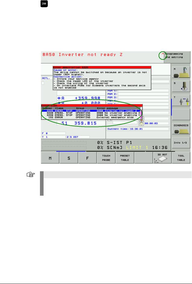
4.3ERR Key
Display all pending error messages
(if this key is pressed again, the window will be closed)
If there is an AND symbol (little red roof) in the header in addition to the error message, there is more than one pending error message.
The ERR key (ERROR) is located directly over the HELP key. If this key is pressed, an error list appears. All pending NC and PLC error messages of the control are displayed in an own window. In addition, the help window can be called with the HELP key.
Note
If there is no ERR key over the HELP key on your keyboard, press the corresponding space bar over the HELP key. —> If the NC software of the iTNC 530 supports the function of the ERR key, the ERR list can also be called!
|
4 – 20 |
HEIDENHAIN Service Manual iTNC 530 |
![]()
The ERR window is described below:
|
Column |
Description |
|
Number |
Error number that was defined by HEIDENHAIN or the machine manufacturer |
|
(-1: No error number defined) |
|
|
Class |
Error class. Defines the reaction of the control: |
|
ERROR |
|
|
Program run is interrupted by the TNC (INTERNER STOP) |
|
|
FEED HOLD |
|
|
The feed rate enable is deleted |
|
|
PGM HOLD |
|
|
The program run is interrupted (control-in-operation symbol blinking) |
|
|
PGM ABORT |
|
|
The program run is aborted (INTERNER STOP) |
|
|
EMERG. STOP |
|
|
EMERGENCY STOP is generated |
|
|
RESET |
|
|
TNC executes a warm start |
|
|
WARNING |
|
|
Warning message, program run is continued |
|
|
INFO |
|
|
Info message, program run is continued |
|
|
Group |
Error source. |
|
GENERAL |
|
|
General error |
|
|
OPERATING |
|
|
Error during machining and machine traverse |
|
|
PROGRAMMING |
|
|
Error during programming |
|
|
PLC |
|
|
PLC error message of the machine manufacturer |
|
|
Error |
Displayed error text |
|
message |
|
The individual error messages can be selected with the cursor; the open help window shows the appertaining text.
4.4CE Key
Delete the error message
Displayed error messages can be acknowledged with the CE key.
If the error cause is still existing, the corresponding error message is displayed again. —> Eliminate the error!
Note
Messages regarding very fatal errors, cannot be confirmed with the CE key.
The control must be rebooted.—> Press the END key.
If this does not function … —> Switch the power switch of the machine off and on again.

4.5List of NC Error Messages
You can find the complete list of NC error messages (incl. operation errors) on the DVD TNCguide in several languages and sorted by error numbers. These TNCguide information can also be found on our website http://www.heidenhain.de/Services/…
Note
Where it is possible and makes sense, you may switch the control off and on again to observe whether the error message is generated again afterwards.
Note:
In the next version of this Service Manual the list of NC error messages will be filtered for error messages that indicate a technical defect.
Information and links to suitable routines for error diagnosis will be included!
|
4 – 22 |
HEIDENHAIN Service Manual iTNC 530 |

5 Errors
5.1Introduction
Not all error conditions on the control or machine can be shown by error messages on the monitor.
Therefore, this chapter gives you an overview of errors with notes and tips how to proceed.
What is the cause of Ask the last operator or technician who has worked with or on the machine about the course the error? of events.
Have there been any particular incidences, such as …
Cleaning of the machine (humidity, etc.)
Thunderstorms
Modifications to the machine
NC software update
New machining program
Tool breakage
Collision
Power failure
Etc.
The error diagnosis will be easier for you by pointed questions and precise answers!
|
Static and nonstatic |
Errors can also be defined in the categories of static errors (e.g., interruption in the electrical |
|
errors |
cabinet, defective unit) and nonstatic errors (e.g., loose connection, shielding problems, |
|
interferences). |
|
|
Naturally, the error location of static errors is easier. |
|
|
Sporadic and |
Check whether you can reproduce a certain error on the machine at any time (nonsporadic error). |
|
nonsporadic |
This assists you in trouble shooting. |
|
errors |
The integrated log or the PLC logic diagram are some possibilities to investigate sporadic errors. |
5.2Notes and Tips
|
Comparison with |
If a dimensionally identical or similar machine is available, the functionality of this machine can |
|
functioning |
be compared with the defective machine. |
|
machines |
This can be very helpful for trouble shooting! |
Connectors and Observe the following during connecting and disconnecting:
females
D-Sub Connectors or Females
Connect and disconnect straightly! Otherwise, the spring contact in the D-sub connectors could be widened. This may result in contact problems!
Ribbon Connectors or Females
Connect carefully and straightly with constant pressure to prevent a deflection of the males.
Signal Socket at the Motor
Slide the nib of the connector into the notch of the signal socket and screw the connector straightly. Do not use force! Otherwise the males could be bent or even pressed into the socket.

Low voltages |
All units connected to the control are also supplied by the control (encoders with long |
|
cables are maybe provided with voltage amplifiers). It is thus possible that defective connected |
|
|
units or also damaged cables have an influence on the low voltages in the control and generate |
|
|
a variety of error messages. |
|
|
Only the newer control hardware is equipped with the so-called polyfuses. These are electronic |
|
|
fuses that separate defective peripheral units from the low voltages in the control in case of an |
|
|
error. Polyfuses are equipped with a self-resetting function («self-healing effect») |
|
|
Always disconnect suspicious units from the control for error diagnosis! |
|
|
If necessary, deactivate these units or the axis concerned in the machine parameter list. |
Note
It is not sufficient to deactivate a suspicious axis with machine parameter MP10 (without disconnecting suspicious units).
The corresponding units (e.g., position encoder for this axis) are not monitored any more but are still supplied with power. The defective scale can thus influence the low voltages of the control, for example!
Note
If you are not in a position/allowed to activate the axes with MP10, MP subfiles might be active and/or this is not permitted by the PLC program. —> Ask the machine manufacturer!
Switch on the control and check whether errors still occur.
Caution
For trouble shooting do not connect obviously defective controls (e.g., position encoder with short circuit after entering of humidity) to other input connectors (z.B. X1-X6, X35-X38) of the control.
Defective cables may result in interruptions but also in undefined conditions and direct error messages. Therefore, especially check possible worn and squeezed positions of the cables.
|
Shielding and |
Also defective shieldings and groundings can result in undefined errors or in a malfunction |
|
grounding |
of the machine (e.g., vibration of axes, poor surface of the workpiece). The reason are |
|
compensating currents that are caused by potential differences. |
|
|
Therefore, check the terminals, shielded cables (the shielding braid must not contact the 0 V |
|
|
conductor inside the cable), cover plates, grounding bars, contact plates, etc. |
Caution
If HEIDENHAIN expansion boards for the SIMODRIVE system are used, please check the mandatory grounding.
—> See “Important Notes on the Use of HEIDENHAIN Interface Boards in SIMODRIVE System” on page 29.
|
5 – 24 |
HEIDENHAIN Service Manual iTNC 530 |

|
Sources of |
Also observe likely sources of interference that may have a negative effect on the connected |
|
interference |
units. |
|
Noise is mainly produced by capacitive and inductive coupling from electrical conductors or from |
|
|
device inputs/outputs, such as … |
|
|
Strong magnetic fields from transformers or electric motors |
|
|
Relays, contactors and solenoid valves |
|
|
High-frequency equipment, pulse equipment and stray magnetic fields from switch-mode |
|
|
power supplies |
|
|
Power lines and leads to the above equipment |
Make sure that …
There is a minimum distance of 20 cm from the MC 42x(B), CC 42x and its leads to interfering equipment.
There is a minimum distance of 10 cm from the MC 42x(B), CC 42x and its leads to cables that carry interference signals. For cables in metallic ducting, adequate decoupling can be achieved by using a grounded separation shield.
The cross section of potential compensating lines is min. 6 mm2.
Contact the machine manufacturer if these conditions are not fulfilled!
|
Caution |
||||
|
Only use original HEIDENHAIN cables, connectors and couplings as replacement! |
||||
Contamination |
Pay special attention to contaminated units (oil, grease, dust, etc.)! |
|||
|
What could be the reason for the contamination? |
||||
|
Some examples: |
||||
|
Machining of graphite |
||||
|
Coolant or coolant vapor |
||||
|
Defective filter system in the electrical cabinet (filter pads) |
||||
|
Oil or oil vapor |
||||
|
Oil in the compressed-air system |
||||
Humidity |
Check whether humidity has entered the units! |
|||
|
What could be the reason? |
||||
|
Some examples: |
||||
|
Defective climate control unit in the electrical cabinet |
||||
|
Coolant or coolant vapor |
||||
|
Condensation of boards due to differences in temperature |
||||
|
Defective tubes, sealings, etc. |
||||
|
Shipping brace of |
Check whether the shipping brace of the hard disk of the mounted control has |
|||
|
the hard disk |
been removed. |

5.3Overview of Possible Errors
This table shows an overview of specific errors on the machine or control, possible causes of the errors as well as measures for correcting these errors.
The potential measures for correcting the errors are described in more detail in the corresponding chapters.
Note
Where it is possible and makes sense, you may switch the control off and on again to observe whether the error is generated again afterwards.
|
Error |
Possible Cause of Error |
Measures for Error Diagnosis and/ |
|
or Corrective action |
||
|
The iTNC monitor remains dark after the |
iTNC monitor defective |
Check the visual display unit; |
|
machine has been switched on. |
Power supply to monitor |
See “Visual Display Unit” on |
|
defective |
page 353 |
|
|
Check power supply of the MC; |
||
|
Power supply of the MC |
||
|
See “Power Supply” on page 205 |
||
|
defective |
||
|
Disconnect defective or suspicious |
||
|
Defective unit connected to the |
||
|
control (short circuit, etc.) |
units or cables, See “Low volta- |
|
|
ges” on page 24 |
||
|
The control does not boot completely (error |
Hard disk defective |
Exchange MC or HDR or drive |
|
messages regarding the boot process are |
assembly; See “Exchange of |
|
|
sometimes displayed). |
HEIDENHAIN Components” on |
|
|
page 411 |
||
|
The message «RELAY EXTERNAL DC |
EMERGENCY STOP chain |
Check output «Control is ready» and |
|
VOLTAGE MISSING» does not disappear |
interrupted |
acknowledgement I3; See |
|
although the key «Control voltage ON» is |
24 V power supply (connector) |
“Checking the Enables on the |
|
pressed. |
X34 missing |
iTNC” on page 311 |
|
MC defective |
||
|
When the machine is switched on, the error |
Wiring defective, contactors |
Check the related components; |
|
message «EMERGENCY STOP defective» |
defective or too slow |
See “Error message EMERGENCY |
|
MC defective |
STOP DEFECTIVE” on page 317 |
|
|
During switch-on or operation DSP errors |
Data loss on the hard disk in the |
Check the hard disk; See “Hard |
|
are generated. A mechanical reason or a |
range of the SYS partition. |
Disk Test” on page 233 |
|
defective unit can be ruled out. |
Activate the NC software again; |
|
|
See “Activating the NC Software |
||
|
Used on the Machine” on page 453 |
||
|
The «Power interrupted» message cannot |
The key gets caught |
See “Keyboard Unit” on page 357 |
|
be confirmed or the login password cannot |
||
|
be entered in a dual-processor control. |
||
|
The machine cannot be referenced after |
Interruption between the |
Eliminate the interruption, repair |
|
switch-on or the axes cannot be moved |
NC-stop key and control (the |
the key, etc. |
|
during operation or the spindle cannot be |
NC-stop signal is lowactive) |
See “Machine Operating Panel” on |
|
switched on during operation. |
page 385 |
|
|
The machine is in the mode «Cross over |
Inverter system is not ready |
See “Checking the Readiness of |
|
reference points» which is neither possible |
for operation |
the Inverter System” on page 322 |
|
with the NC-START key nor with the axis |
||
|
direction keys. |
||
|
During reference run, the machine moves |
The trip dogs for the reversal |
See “Referencing” on page 301 |
|
to the limit switch. |
of direction during reference run |
|
|
are defective |
||
|
During reference run, the machine moves |
The machine was switched off |
Referencing with axis-direction |
|
to the mechanical stop (for machines |
at the wrong position |
keys (no automatic reference mark |
|
without limit stop). |
traverse)! |
|
|
An error message is sometimes displayed, |
||
|
e.g. «8640 I2T value of motor is too high …» |
||
|
5 – 26 |
HEIDENHAIN Service Manual iTNC 530 |

|
Error |
Possible Cause of Error |
Measures for Error Diagnosis and/ |
|
|
or Corrective action |
|||
|
iTNC monitor is frozen. |
Power failure |
Check the primary supply (cables, |
|
|
The control has locked up. |
Failure of one or several phases |
fuses, terminals); |
|
|
The main switch has to be switched off and |
in the supply line |
See “Power Supply” on page 205 |
|
|
on again. |
The power supply voltage has |
Check the wiring of the inverter |
|
|
After reset of the control«Power fail |
fallen below the minimum value |
system, see circuit diagrams of the |
|
|
Interrupt!» is entered in the log of new |
Interruption in the electrical |
machine manufacturer |
|
|
software versions. |
Check the functioning of the |
||
|
cabinet |
|||
|
inverter system or the motor (see |
|||
|
Inverter (power supply module) |
|||
|
Service Manual for Inverter |
|||
|
defective |
|||
|
Systems and Motors) |
|||
|
Short circuit of drives (drive |
|||
|
modules, motors) |
|||
|
STIB («Control-in-operation = «*» in status |
Axis did not reach the posi- |
Carry out drift adjustment; |
|
|
display) remains in place even though |
tioning window |
See “Interface to the Drives” on |
|
|
positioning appears to be completed. |
Excessive drift of analog axes |
page 327 |
|
|
The next NC block is not executed in the |
Approach behavior of axis not |
Re-optimization or new |
|
|
automatic operating modes , the NC |
optimized |
optimization of the axis by the |
|
|
program gets caught. |
machine manufacturer |
||
|
«Vibrating» axes, sometimes connected |
Poor shielding or grounding |
Check the grounding of your |
|
|
with loud noises. |
Connectors on grounding termi- |
machine, refer to the machine |
|
|
nal X131 of infeed/regenerative |
manufacturer |
||
|
module (Simodrive 611D) not |
Ensure the grounding clamps are |
||
|
properly wired |
secure |
||
|
Grounding terminal X131 of |
Check the shielding or the covers |
||
|
power supply module |
|||
|
(Simodrive 611D) or grounding |
|||
|
connection damaged |
|||
|
Servo lag is too high at standstill |
Electrical offset of analog axes |
Carry out offset adjustment; |
|
|
See “Adjusting the Electrical Offset |
|||
|
(Drift Adjustment)” on page 346 |
|||
|
Error messages regarding encoders or |
Probe or handwheel that were |
Disconnect the probe and |
|
|
other connected units are generated |
exposed to humidity (coolant, |
handwheel including the cables. |
|
|
although you find out that these do not |
etc.) or have been damaged. |
Screw the dummy plug |
|
|
cause the errors! |
—> Supply voltages (5 V, 12 V, |
(ID 271958-03) instead of the hand- |
|
|
15 V) are impaired. A variety of |
wheel or bridge the handwheel in |
||
|
error messages are possible. |
the EMERGENCY STOP chain. |
||
|
Deactivate the handwheel in |
|||
|
MP7640. Check whether the |
|||
|
error messages are still generated. |
|||
|
Various error messages are generated but |
Connection (short circuit) of |
Check the cables for damage. |
|
|
are not substantiated. |
shielding potential (chassis, |
Check the machine for correct |
|
|
cable shielding) with 0 V voltage |
shielding (ask the machine manu- |
||
|
potential of the NC power |
facturer). |
||
|
supply |
|||
|
NC functions do not function any more |
Data loss on the hard disk in the |
Check the hard disk; |
|
|
(There might be an information by the |
range of the SYS partition |
See “Hard Disk Test” on page 233 |
|
|
control that the corresponding files have |
Activate the NC software again; |
||
|
been deleted). |
See “Activating the NC Software |
||
|
Used on the Machine” on page 453 |
|||
|
Bucking of the analog axis |
Carbon brushes for power |
Exchange the carbon brushes |
|
|
supply or tachometer measu- |
|||
|
ring that have been abrided on |
|||
|
one side or used up |
|||
|
The axes cannot be traversed and the red |
Drive release missing |
See “Checking the Enables on the |
|
|
LEDs SH2 of all HEIDENHAIN drive |
iTNC” on page 311 |
||
|
modules light up (or the red LEDs SH2 or |
|||
|
RESET of the HEIDENHAIN interface cards |
|||
|
for the SIMODRIVE system) |
|||
|
There are repeated hard disk errors |
Defects on the hard disk |
Check the hard disk; See “Hard |
|
|
Defective unit connected to the |
Disk Test” on page 233 |
||
|
control (short circuit, etc.) |
Disconnect suspicious units; |
||
|
See “Notes and Tips” on page 23 |
|||

|
Error |
Possible Cause of Error |
Measures for Error Diagnosis and/ |
|
or Corrective action |
||
|
During processing the motors run (axes, |
Defective braking resistor |
Check the primary supply (cables, |
|
spindle) down out of loop. |
(conversion of electrical energy |
fuses, terminals); |
|
to heat energy not possible) |
See “Power Supply” on page 205 |
|
|
Defective infeed/regenerative |
Check the functioning of the |
|
|
feedback module (energy |
inverter system or the braking |
|
|
recovery not possible) |
resistor; |
|
|
Interruption in the primary |
See Service Manual for Inverter |
|
|
Systems and Motors |
||
|
supply (fuses, wires, etc.; |
||
|
Check the wiring of the inverter |
||
|
energy recovery not possible) |
||
|
system, see circuit diagrams of the |
||
|
machine manufacturer |
||
|
An axis is to be traversed and an error |
Brake not released |
Check whether the brake is |
|
message is displayed, e.g. «8640 I2T value |
released |
|
|
of motor is too high …» |
Check the wiring of the motor |
|
|
(or a similar error message that indicates an |
system; |
|
|
excessive load of the drive) |
See circuit diagrams of the |
|
|
machine manufacturer |
||
|
Some HEIDENHAIN inverters can |
||
|
control the motor brakes; |
||
|
See Service Manual for Inverter |
||
|
Systems and Motors |
||
|
5 – 28 |
HEIDENHAIN Service Manual iTNC 530 |

5.4Important Notes on the Use of HEIDENHAIN Interface Boards in SIMODRIVE System
|
Version with |
HEIDENHAIN interface boards for the SIMODRIVE system in the version with D-Sub connector |
|
D-Sub connector |
are available with or without metallic insulation of HEIDENHAIN PWM signals to the Siemens |
|
interface. |
Interface boards without metallic insulation are recognized as follows:
On the front panel there are the LEDs NB (not ready) and IF (pulse release).
There is no grounding screw on the front panel.
There is no transformer on the front panel.
These board have the Id.Nr. 291070-01, 324952-01, 02, 03 and 10 without index A.
Caution
The terminal X131 of the Siemens E/R module of boards without metallic insulation may not be connected to the central signal ground of the machine!
Note
The HEIDENHAIN interface boards of the first generation were built without metallic insulation.

Interface boards with metallic insulation are distinguished as follows:
On the front panel there are the LEDs RESET X1, READY and RESET X2.
There is a grounding screw on the front panel.
There is no transformer on the front panel.
These boards have the ID 324952-10 with index
A, 11, 12, …
Transformer component on the board
Grounding screw on the front panel
|
5 – 30 |
HEIDENHAIN Service Manual iTNC 530 |
![]()
Caution
The terminal X131 of the Siemens E/R module of boards with metallic insulation has to be connected to the central signal ground of the machine!
Caution
Interface boards with and without metallic insulation must not be used together! Either all boards have a metallic insulation and X131 is wired or all cards do not have
a metallic insulation and X131 is not wired!
Siemens E/R module with X131

Siemens UEB module with X131
Caution
If a Siemens E/R module is used together with the so-called monitoring module (UEB module) , the terminal X131 on this module has to be wired as on the E/R module!
|
5 – 32 |
HEIDENHAIN Service Manual iTNC 530 |

Version with ribbon HEIDENHAIN interface boards for the SIMODRIVE system in the version with ribbon cable have cable connector a metallic insulation of the HEIDENHAIN PWM signals to the Siemens interface.
Thus X131 of the Siemens drive system must be wired!

|
5 – 34 |
HEIDENHAIN Service Manual iTNC 530 |

6 Log
6.1General
The log serves as a troubleshooting aid.
For this purpose 4 MB memories are reserved in the control.
Error messages and keystrokes are recorded in a process memory. If you intend to perform tests and to see the entries in the log, you have to call it each time again.
Error messages and key strokes are stored in the log.
The sources of the keystrokes are entered in INFO: MAIN KEYSOURCE: <source>. <source> may include following entries:
—KEYBOARD
—PLC
—PLCNCSTART
—HANDWHEEL
—LSV2
Note
The first soft key (down left on the screen) is recorded in the log as soft key 0, the second soft key as soft key 1, etc.
The arrow keys for the switching of the soft-key rows are recorded. Any newly called soft-key row starts again with soft key 0.
All entries show the date and the local time.
The machine manufacturer can use up to 8 additional OEM logs. —> If necessary, ask your machine manufacturer if these OEM logs are used and which information is available for the service technician.
Note
Following messages are not shown in the log:
File system error x
Reason: In case of a write or read error all write activities on the hard disk are always interrupted as data cannot be written reliably any more.
Relay external DC voltage missing
Reason: This message is always displayed on the monitor after confirming the message Power interrupted. This is an information, not an error message. An entry in the log is not made.

6.2Calling the Log
Enter the code number LOGBOOK. —> See “Code Numbers” on page 13.
The following screen is displayed:
If you wish, you may change the path and the file name in this selection window.
Default setting: TNC:LOGBOOK.A.
Here you can also define the starting point and the end point for reading out the log.
Note
Ensure correct spelling when making any changes in the log window!
Then start reading out the log by pressing the EXECUTE soft key.
An ASCII file with the log entries is generated and displayed on the screen!
Note
The log can be read out directly from the PC/laptop with the HEIDENHAIN software tool TNCremoNT. The code number LOGBOOK has not to be entered on the control.
The local time on the control and the PC/laptop should be identical!
|
6 – 36 |
HEIDENHAIN Service Manual iTNC 530 |

6.3Overview of Log Entries
|
Entry |
Description |
|
|
RESET |
Restart of the control |
|
|
ERR |
Error Messages |
|
|
P —> PLC error message with line number in the |
||
|
PLC error text file |
||
|
N —> NC error message with number |
||
|
Power fail interrupt ! —> Control is switched off by |
||
|
a POWERFAIL |
||
|
Result of the file system test: |
||
|
If the control is not properly shut down, the file |
||
|
system is checked during the next startup and the |
||
|
result is entered in the log. |
||
|
—> Search in the log for «dosfsck -a» |
||
|
INFO |
MAIN ERRCLEARED |
Confirmation of an error message |
|
INFO |
MAIN ERR_RECURED |
Error message entered several times |
|
KEY |
Key strokes |
|
|
INFO |
MAIN SOFTKEY |
Path with appropriate image file of a pressed soft key |
|
STIBa |
ON |
«Control-in-operation» on |
|
OFF |
«Control-in-operation» off |
|
|
BLINK |
«Control-in-operation» blinking |
|
|
INFO |
MAIN START |
Control model and NC software |
|
INFO |
MAIN FILE DEL |
Faulty files on the hard disk, to be erased during |
|
booting |
||
|
INFO |
MAIN CYCLES |
Test results for fixed cycles and touch probe cycles |
|
INFO |
MAIN KEYSOURCE |
Source of the keystrokes |
|
KEYBOARD |
||
|
PLC |
||
|
PLCNCSTART |
||
|
HANDWHEEL |
||
|
LSV2 |
||
a. Control-in-operation symbol = «* » in the screen display

|
Entry |
Description |
||||
|
INFO |
MAIN PGM |
Started NC program or NC macro |
|||
|
INFO |
MAIN LINE |
Line number of the started NC program or NC macro |
|||
|
INFO |
MAIN PGMEND |
Information about the program end in program run |
|||
|
Byte 0/1 |
00 01 |
Emergency stop |
|||
|
00 02 |
Positioning error |
||||
|
00 03 |
Programmed stop |
||||
|
00 04 |
Block end for single block |
||||
|
00 05 |
Geometry error |
||||
|
00 06 |
END PGM, M02 |
||||
|
00 07 |
Internal stop key |
||||
|
00 08 |
Data transfer error |
||||
|
(V.24/V.11) |
|||||
|
In addition, when an NC program is stopped by an |
|||||
|
error message, the following information is entered: |
|||||
|
NC program, line number, actual position, datum, |
|||||
|
datum shifts, tool number |
|||||
|
INFO |
MAIN MACEND |
Information about the end of an NC macro |
|||
|
Byte 0/1 |
00 01 |
Emergency stop |
|||
|
00 02 |
Positioning error |
||||
|
00 03 |
Programmed stop |
||||
|
00 04 |
Block end for single block |
||||
|
00 05 |
Geometry error |
||||
|
00 06 |
END PGM, M02 |
||||
|
00 07 |
Internal stop key |
||||
|
00 08 |
Data transfer error |
||||
|
(V.24/V.11) |
|||||
|
INFO |
MAIN PATH |
PLCEDIT |
File for PLC Editor |
||
|
NCEDIT |
File for NC Editor |
||||
|
RUNPGM |
Main program for program run |
||||
|
RUNPALET |
Pallet table for program run |
||||
|
RUNDATUM |
Datum table for program run |
||||
|
RUNTOOL |
Tool table for program run |
||||
|
RUNTCH |
Pocket table for program run |
||||
|
SIMPGM |
Main program for program test |
||||
|
SIMDATUM |
Datum table for program test |
||||
|
SIMTOOL |
Tool table for program test |
||||
|
RUNBRKPGM |
Stopping point for block scan |
||||
|
SIMBRKPGM |
Stopping point for program test |
||||
|
RUNPRINT |
Path for FN15: PRINT for program run |
||||
|
SIMPRINT |
Path for FN15: PRINT for program test |
||||
|
MDIPGM |
File for positioning with manual data input |
||||
|
NCFMASK |
Mask for file management in the NC area |
||||
|
PLCFMASK |
Mask for file management in the PLC area |
||||
|
EASYDIR |
Paths for standard file management |
||||
|
TCHPATH |
Datum table for manual measurement |
||||
|
SIMTAB |
Freely definable table in program test |
||||
|
RUNTAB |
Freely definable table in program run |
||||
|
KINTAB |
Active kinematic table |
||||
|
6 – 38 |
HEIDENHAIN Service Manual iTNC 530 |

|
Entry |
Description |
|||
|
INFO |
MAIN NCEVENT |
Entries through FN38: SEND of the operating mode |
||
|
Program Run, Full Sequence or Program Run, |
||||
|
Single Block |
||||
|
MAIN NCTEVENT |
Entries through FN38: SEND of the operating mode |
|||
|
Test Run |
||||
|
INFO |
PLC <log identifier> |
Entries through PLC Modules 9275 and 9276 |
||
|
WARNING |
||||
|
ERROR |
||||
|
INFO |
SYS |
SHUTDOWN |
Shut down the control |
|
|
REBOOT-TNC |
Reboot the control |
|||
|
INFOa |
REMO A_LG |
Log in with LSV2 protocol |
||
|
REMO A_LO |
Log out with LSV2 protocol |
|||
|
REMO C_LK |
LSV2 protocol: |
|||
|
Locking and releasing the keyboard; the key codes |
||||
|
between locking and releasing are sent via LSV2 |
||||
|
protocol |
||||
a.For testing all LSV-2 telegrams can be entered in the log. This function has to be released after entering the code number LOGBOOK via soft key LSV-2 TELEGRAM ON OFF .
|
Entry of operating- |
Operating-system error messages require a rebooting of the control. During rebooting the |
|
system error |
operating-system error message is entered in the log. The time when the operating-system error |
|
messages |
message is entered in the log is indicated, i.e., the reboot time. In the headline of the operating- |
|
system error message the Greenwich Mean Time (Universal Time) is shown. |
|
|
Entry of |
Not each single block of an NC program is recorded in the log (this would exceed the size of the |
|
NC programs |
log file). You receive information on the start and end of an NC program. Information about |
|
the program end is shown in … |
|
|
Byte 0 and 1 |
|
|
Conversational language in the line Stop reason: … |
|
|
You receive further information on … |
|
|
Line number of the NC program at program end |
|
|
ACTUAL position at program end |
|
|
Active preset values, if available |
|
|
Set datum shift, if available |
|
|
Tool number |
|
|
Tool length, tool radius, etc. |

6.4Example of a Log Entry
|
STIB: |
ON |
20.01.2001 14:01:42 |
|||||||||||||||||
|
INFO: |
MAIN |
PGM |
20.01.2001 14:01:42 |
||||||||||||||||
|
TNC:mercedesMbprog5a.I |
|||||||||||||||||||
|
INFO: |
MAIN |
LINE |
20.01.2001 14:01:42 |
||||||||||||||||
|
0 |
|||||||||||||||||||
|
STIB: |
OFF |
20.01.2001 14:01:44 |
|||||||||||||||||
|
INFO: |
MAIN |
PGMEND |
20.01.2001 14:01:44 |
||||||||||||||||
|
00 |
01 |
02 |
03 |
04 |
05 |
06 |
07 |
08 |
09 |
0A |
0B |
0C |
0D |
0E |
0F |
||||
|
00 |
02 |
00 |
02 |
00 |
00 |
00 |
33 |
00 |
00 |
00 |
11 |
||||||||
|
Byte 0 |
Byte 1 |
||||||||||||||||||
|
INFO: |
MAIN |
PGMEND |
20.01.2001 14:01:44 |
||||||||||||||||
|
Stop |
reason: Positioning error |
||||||||||||||||||
|
Error |
: 51 |
||||||||||||||||||
|
Error class: «Positioning» |
|||||||||||||||||||
|
NC |
program : TNC:mercedesMbprog5a.I line 17 |
||||||||||||||||||
|
INFO: |
MAIN |
PGMEND |
20.01.2001 14:01:44 |
||||||||||||||||
|
Actual pos.: |
|||||||||||||||||||
|
X |
= |
1.8251 |
|||||||||||||||||
|
Y |
= |
-9.2372 |
|||||||||||||||||
|
Z |
= |
45.0030 |
|||||||||||||||||
|
A |
= |
0.0000 |
|||||||||||||||||
|
B |
= |
359.9999 |
|||||||||||||||||
|
C |
= |
0.0000 |
|||||||||||||||||
|
W |
= |
65.9894 |
|||||||||||||||||
|
Preset |
: (Range = 0) |
||||||||||||||||||
|
X |
= |
-8.6201 |
|||||||||||||||||
|
Y |
= |
7.5515 |
|||||||||||||||||
|
Z |
= |
-1835.3142 |
|||||||||||||||||
|
A |
= |
0.0000 |
|||||||||||||||||
|
B |
= |
0.0000 |
|||||||||||||||||
|
C |
= |
0.0000 |
|||||||||||||||||
|
W |
= |
-178.8965 |
|||||||||||||||||
|
Datum shift: |
|||||||||||||||||||
|
X |
= |
0.0000 |
|||||||||||||||||
|
Y |
= |
0.0000 |
|||||||||||||||||
|
6 – 40 |
HEIDENHAIN Service Manual iTNC 530 |

7 Integrated Diagnosis Functions
7.1Introduction
Example: Display of
the DSP Diagnosis
The iTNC 530 features various diagnosis functions for trouble shooting.
The following tests function for CC 422 as of hardware code 30.
The hardware code is shown after pressing the drive information softkey. —> See description on the following pages.
The drive tests for the CC 424 are not yet supported!
To call the diagnostic functions:
Press the MOD key in the Programming and Editing mode of operation.
Press the DIAGNOSIS soft key.

The following diagnostic functions are available:
Soft key Soft key Soft key Function
Various drive diagnosis functions can be selected after pressing this soft key.
Before selecting the diagnostic function, under Supply unit you must select the power supply unit being used, so that the signals present are not interpreted as errors.
The integrated oscilloscope is started. (See “Integrated
Oscilloscope” on page 49)
Presents a graphically supported, dynamic display of various release, inverter and PLC signals. Use the soft keys for scrolling to switch between controller and control-loop specific signals, See “Meanings of the Signals under “DSP”” on page 43
Presents a display of the analog signals available to the drive controller (n. p. = signal not present).
A display with all available analog values appears.
In Overview of all drives you use these soft keys to select a drive. The following soft keys display more detailed information.
If an absolute speed encoder with EnDat interface is connected, a detailed display of the encoder information appears.
If an absolute position encoder with EnDat interface is connected, a detailed display of the encoder information appears.
The motor data for the selected motor is displayed from the motor table.
If a HEIDENHAIN motor with electronic ID label is connected, the information stored in the ID label is displayed.
If a HEIDENHAIN power module with an electronic ID label is connected, the information stored in the ID label is displayed.
The file TNC:herosdiagnose.txt is created after pressing this soft key. HEIDENHAIN uses this file for diagnosis of the operating system.
|
7 – 42 |
HEIDENHAIN Service Manual iTNC 530 |

7.2Meanings of the Signals under “DSP”
Controller specific
|
Signal |
Meaning |
Colors |
|
External enabling signals |
||
|
Control-is-ready |
The signal NE1 (emergency stop input 1, |
Gray: No information about the |
|
acknowledgment |
MC) is active if a 0-level is present (low |
signal available |
|
(–NE1) |
active). For the iTNC 530 the |
Green: Signal is not active, enable |
|
corresponding input is located at |
Red: Signal is not active, no |
|
|
connector X42/I3 (PLC input), and is |
||
|
enabling |
||
|
looped to the MC as a hardware line. |
||
|
Drive enabling |
The signal NE2 (emergency stop input 2, |
Gray: No information about the |
|
(–NE2) |
CC) is active if a 0-level is present (Low |
signal available |
|
active). For the iTNC 530 the |
Green: Signal is not active, enable |
|
|
corresponding input is located at |
Red: Signal is not active, no |
|
|
connector X42/I32 (PLC input), and is |
||
|
enabling |
||
|
looped to the CC as a hardware line. |
||
|
Powerfail |
The PF signal shows the status of the |
Gray: No information available |
|
«effective» powerfail signal for the drive |
Green: Enable PF not active |
|
|
controller. The signal results from gating |
(1-level) |
|
|
the PF.PS.ZK (powerfail dc-link) and |
Red: PF is active (0-level), the dc- |
|
|
PF.PS.AC (AC fail). The gating can be set |
||
|
link voltage has decreased below |
||
|
via machine parameter and via PLC. |
a permissible (inverter-specific) |
|
|
level or the phase monitoring |
||
|
responded; no enabling |
||
|
MC ready (–WD) |
This signal shows that the MC is ready for |
Gray: No information available |
|
control. This signal is a possible reason |
Green: Enable ME not active |
|
|
that the power module was switched off |
(1-level) |
|
|
via SH1. |
Red: Do not enable: WD1 is active |
|
|
(0-level), the MC’s watchdog is |
||
|
not retriggered. This signal is |
||
|
transmitted as SH1 to the inverter |
||
|
(SH1 can also be generated by |
||
|
other signal sources). |
||
|
Powerfail (ZK) |
The signal is generated at the inverter, |
Gray: No information available |
|
and is led via the supply bus to the drive |
Green: Enable Powerfail (ZK) is |
|
|
controller. The input at the drive controller |
inactive (1-level) |
|
|
is displayed. Depending on the wiring, |
Red: Do not enable: Powerfail (ZK) |
|
|
either this signal or Powerfail (AC) is |
is active (0-level), the dc-link |
|
|
relayed on the controller PCB to the |
voltage has decreased below a |
|
|
powerfail signal. |
permissible level (inverter- |
|
|
specific). |
||
|
Powerfail (AC) |
The signal is generated at the inverter, |
Gray: No information available |
|
and is led via the supply bus to the drive |
Green: Enable Powerfail (ZK) is |
|
|
controller. The input at the drive controller |
inactive (1-level) |
|
|
is displayed. Depending on the wiring, |
Red: Do not enable: Powerfail |
|
|
either this signal or Powerfail (ZK) is |
(AC) is active (0-level), phase |
|
|
relayed on the controller PCB to the |
monitoring responded, at least |
|
|
powerfail signal. Powerfail (AC) does not |
one power supply phase failed. |
|
|
exist for all supply units (e.g., not UV 130). |
||
|
Internal enabling signals |
||
|
CC controller |
If no error is present in the drive controller |
Gray: No information about the |
|
ready |
and the CC was started, “ready for |
signal available |
|
control” is reported. |
Green: Enable, CC is ready for |
|
|
control |
||
|
Red: Do not enable |
||

|
Signal |
Meaning |
Colors |
|
Clearable DSP |
Clearable DSP errors are 2nd class errors |
Gray: No information about the |
|
error |
(such as motor temperature). The CC can |
signal available |
|
only resume control after the error has |
Green: Enable: There is no |
|
|
been cleared (by pressing the CE key). |
(clearable) 2nd class error |
|
|
Red: Do not enable: There is no |
||
|
(clearable) 2nd class error |
||
|
Current |
This signal is activated by the current |
Gray: No information about the |
|
controller’s |
controller’s watchdog. It influences SH2 |
signal available |
|
watchdog |
at the power module via the PWM |
Green: Enable, current controller’s |
|
interface. |
watchdog is OK |
|
|
Red: Do not enable: Current |
||
|
controller’s watchdog is active (0- |
||
|
level). No pulse release from the |
||
|
current controller via the PWM |
||
|
interface |
||
|
Signals of power supply unit |
||
|
DC-link voltage >> |
The signal reports the status of the dc-link |
Gray: No information about the |
|
voltage: Either it is OK or too high. This |
signal available |
|
|
signal also switches off all power |
Green: DC-link voltage OK |
|
|
modules (via the device bus). |
Red: DC-link voltage too high |
|
|
Possible cause of error: |
||
|
Missing or faulty braking resistor |
||
|
Excessive braking power |
||
|
Temperature |
The signal reports the status of the heat |
Gray: No information about the |
|
sink temperature in the inverter: Either it |
signal available |
|
|
is OK or too high. |
Green: Temperature OK |
|
|
Red: Temperature too high |
||
|
DC-link current >> |
The signal reports the status of the dc-link |
Gray: No information about the |
|
current: Either it is OK or too high. Both |
signal available |
|
|
positive and negative dc-link currents are |
Green: DC-link current OK |
|
|
evaluated. |
Red: DC-link current too high |
|
|
Power supply unit |
The signal reports the ready status of the |
Gray: No information about the |
|
ready |
supply unit: Supply unit OK, Main |
signal available |
|
contactor on, or supply unit not ready. |
Green: Power supply unit OK, |
|
|
main contactor switched on |
||
|
Red: Power supply unit not ready |
||
|
for operation |
||
|
Short circuit to |
The signal reports the status of the |
Gray: No information about the |
|
ground |
leakage current monitoring: Either it is OK |
signal available |
|
or too high or short circuit to ground |
Green: Leakage current OK |
|
|
Red: Leakage current too high or |
||
|
short circuit to ground |
||
|
Control-loop specific |
|
Signal |
Meaning |
Colors |
|
Temperature of power |
The signal reports the status of the heat |
Gray: No information about |
|
module |
sink temperature in the power module: |
the signal available |
|
Either it is OK or too high. |
Green: Temperature of |
|
|
power module OK |
||
|
Red: Temperature of power |
||
|
module too high |
||
|
Power module switch- |
The signal shows that the IGBT in the |
Gray: No information about |
|
off (IGBT) |
power module has been switched off. |
the signal available |
|
Green: No power module |
||
|
switch-off (IGBT) |
||
|
Red: Power module |
||
|
switch-off (IGBT) |
||
|
7 – 44 |
HEIDENHAIN Service Manual iTNC 530 |

|
Signal |
Meaning |
Colors |
|
Power module unit |
The power module is ready: |
Gray: No information about |
|
ready (LT-RDY) |
Safety relay has picked up |
the signal available |
|
Green: Power module is |
||
|
Main contactor is switched on |
||
|
ready |
||
|
SH1 (MC) is “High” |
||
|
Red: Power supply unit not |
||
|
No error from the power module |
ready for operation |
|
|
MC enabling marker |
The MC can accelerate the switch-off via |
Gray: No information about |
|
this marker. |
the signal available |
|
|
Green: Enabling |
||
|
Red: Do not enable |
||
|
X150/X151 drive |
The signal shows the enabling status for |
Gray: No information about |
|
enabling |
the “X150/X151” switch-off. The signal is |
the signal available |
|
formed from the status of the inputs |
Green: Enable: There is |
|
|
X150/X151 and the setting in MP2040.x. |
currently no switch-off via |
|
|
X150/X151 |
||
|
Red: Do not enable: The |
||
|
drive is currently switched |
||
|
off or locked via X150/X151 |
||
|
Power module active |
The signal shows the status of the |
Gray: No information about |
|
(–SH2) |
SH2 line to the power module. The |
the signal available |
|
CC activates/deactivates the line for |
Green: Enabling: The signal |
|
|
switching off the power module. |
SH2 is not active |
|
|
Red: No enabling: The |
||
|
signal SH2 is active |
||
|
Current controller active |
This signal shows the status of the |
Gray: No information about |
|
current controller. The current controller |
the signal available |
|
|
is either switched on (in control) or |
Green: Enable: Current |
|
|
switched off. |
controller is switched on (in |
|
|
control) |
||
|
Red: No enabling: Current |
||
|
controller is off |
||
|
Speed controller active |
This signal shows the status of the speed |
Gray: No information about |
|
controller. The speed controller is either |
the signal available |
|
|
switched on (in control) or switched off. |
Green: Enable: Current |
|
|
controller is switched on (in |
||
|
control) |
||
|
Red: No enabling: Speed |
||
|
controller is off |
||

|
Signal |
Meaning |
Colors |
|
Rotor position captured |
This signal gives information about |
Gray: No information about |
|
determining the field angle: |
the signal available |
|
|
Drive is not oriented: |
Green: Field angle has been |
|
|
Motor with rotary encoder without Z1 |
determined |
|
|
Yellow: Field angle has |
||
|
track (incl. linear motors) after the first |
||
|
“Drive on” status |
been determined roughly |
|
|
Dark gray: Field angle has |
||
|
Non-aligned rotary encoder with EnDat |
||
|
interface (incl. linear motors), if the field |
not been determined |
|
|
angle has not yet been determined. |
||
|
Drive is roughly oriented: |
||
|
Motor with rotary encoder without Z1 |
||
|
track (incl. linear motors) after the first |
||
|
“Drive on” status |
||
|
Motor with rotary encoder with Z1 track |
||
|
after it has been read |
||
|
Drive is oriented: |
||
|
Motor with rotary encoder with Z1 track |
||
|
after traversing the reference mark |
||
|
Aligned rotary encoder with EnDat |
||
|
interface immediately after switch-on |
||
|
Non-aligned rotary encoder with EnDat |
||
|
interface immediately if the field angle |
||
|
has already been determined. |
||
|
Motor with rotary encoder without Z1 |
||
|
track after traversing the reference |
||
|
mark if the field angle has already been |
||
|
determined. |
||
|
Brake released |
This signal shows the status of the motor |
Gray: No information about |
|
brake signal on the PWM bus. The signal |
the signal available |
|
|
is led on the power module via a relay to |
Green: Brake released |
|
|
the motor. |
Red: Brake active |
|
|
I2t monitoring |
This signal indicates the current and the |
Gray: No information about |
|
stored status of the I2t-monitoring. |
the signal available |
|
|
Green: No I2t warning so |
||
|
far |
||
|
Yellow: There was already |
||
|
(since switch-on) an I2t |
||
|
warning, but there is no |
||
|
current warning. |
||
|
Orange: I2t warning is now |
||
|
active |
||
|
Axis in position (PLC) |
If the axes have reached the positioning |
Green: Axis in position |
|
window after a movement, the status is |
Yellow: Axis not in position |
|
|
shown in W1026. |
||
|
Position controller |
Position controller closed (W1040 |
Green: Position control loop |
|
closed (PLC) |
inverted) By setting W1040 in the PLC, |
closed |
|
the position control loop is opened by the |
Yellow: Position control |
|
|
PLC program. |
loop open |
|
|
Axis enabled (PLC) |
W1024 shows if the position control loop |
Green: Axis not enabled |
|
is open or closed, and if the axis has been |
Yellow: Axis enabled |
|
|
enabled. |
||
|
Axis in motion (PLC) |
During axis movement, the NC sets the |
Green: Axis in motion |
|
bits in W1026. |
Yellow: Axis is stationary |
|
|
7 – 46 |
HEIDENHAIN Service Manual iTNC 530 |

7.3Electronic ID Label
HEIDENHAIN inverter components of type D, as well as HEIDENHAIN synchronous motors with absolute encoders with EnDat interface, are equipped with an electronic ID label.
The product name, the ID number and the serial number are saved in this ID label. These devices are automatically detected when the control is started.
Load the displayed component to the corresponding machine parameter automatically with the SELECT sof key.
During every further control restart, the control checks whether the connected units with electronic ID label match the entries in MP2100.x or MP2200.x. If necessary, a message window appears and the connected device must be entered into the corresponding machine parameters via soft key.
In exceptional cases, the evaluation of the electronic ID label can be deactivated with MP7690.
MP7690 Evaluation of the electronic ID labels
Input: %xx
Bit0 – HEIDENHAIN power modules
0:Active
1:Inactive
Bit1 – HEIDENHAIN synchronous motors
0:Active
1:Inactive

|
7 – 48 |
HEIDENHAIN Service Manual iTNC 530 |

8 Integrated Oscilloscope
8.1General
The iTNC features an integrated oscilloscope.
Note
The integrated oscilloscope is a useful appliance to investigate errors connected to axis movements.
For example, the comparison of actual-to-nominal values such as distance, velocity, acceleration may give information about possible error locations and reasons.
The oscilloscope has six channels; of those, no more than four can display data from the current and speed controller. If more than four channels are to be displayed from the current and speed controller, the error message
Channel <number> cannot be displayed.
The following signals can be recorded:
Note
All current signals in the integrated oscilloscpe of the CC 422 are displayed as peak values.
All current signals in the integrated oscilloscpe of the CC 424 are displayed as effective values.
|
Signal |
Meaning |
|
Saved |
The last traced signal is shown. |
|
s actual |
Actual position [mm] |
|
s nominal |
Nominal position [mm] |
|
s diff |
Following error of the position controller [mm] |
|
Volt.analog |
Analog axis/spindle: |
|
Analog voltage = nominal velocity value [mV] |
|
|
Actl. speed |
Actual value of the axis feed rate [mm/min]. |
|
Calculated from position encoder |
|
|
Noml. pos |
Nominal value of the axis feed rate [mm/min]. Axis feed rate calculated from |
|
the difference from the nominal position values. The following error is not |
|
|
included. |
|
|
Feed rate |
Contouring feed rate [mm/min] |
|
Position: A |
Signal A of the position encoder |
|
Position: B |
Signal B of the position encoder |
|
V (ACT RPM) |
Shaft speed actual value [mm/min]; |
|
Calculated from rotary speed encoder and standardized with MP1054 |
|
|
V (NOML RPM) |
Nominal velocity value [mm/min]: Output quantity of the position controller |
|
I (INT RPM) |
Integral-action component of the nominal current value [A]; |
|
CC 422: peak value, CC 424: effective value |
|
|
I nominal |
Nominal current value [A] that determines torque; |
|
CC 422: peak value, CC 424: effective value |
|
|
PLC |
The PLC operands (B, W, D, I, O, T, C) are recorded. Enter the operand in the |
|
text box next to PLC. |
|
|
a nominal |
Nominal acceleration value (m/s2) |
|
r nominal |
Nominal jerk value (m/s3) |
|
Pos. diff. |
Difference between position and speed encoder (mm) |
|
a actual |
Actual acceleration value (m/s2). Calculated from position encoder. |
|
r actual |
Actual jerk value [m/s3]; calculated from position encoder. |
|
I2-t (mot.) |
Current value of I2-t monitoring of the motor (%) |

|
Signal |
Meaning |
|
I2-t (p.m.) |
Current value of I2-t monitoring of the power module (%) |
|
Utilization |
Actual utilization of the drive (%) |
|
Block number |
Block numbers of the NC program |
|
Gantry Diff |
Difference between synchronized axes (mm) |
|
U nominal |
Nominal voltage (V) |
|
P mech. |
Mechanical power (W) |
|
P elec. |
Electrical power (W) |
|
M actual |
Actual torque value (Nm) |
|
S noml (f.) |
Nominal position after nominal position value filters (mm) |
|
DSP debug |
Diagnosis function for internal purposes |
|
Contour dev. |
Circular interpolation test, contour deviation (mm) |
|
F TCPM |
Feed rate for the tool point with TCPM |
|
Int. diagn. |
Reserved for internal purposes |
The recorded data remain stored until you start recording again or activate another graphic function.
8.2Setup
Activate the oscilloscope as follows:
Programming and Editing —> MOD key
—> soft keys DIAGNOSIS —> DRIVE DIAGNOSIS —> OSCI or with the code number 688379
The setup menu appears:
Choose the parameters to be entered with the cursor keys.
Open the selection window with the GOTO key.
Use the cursor to select a value and confirm it with the ENT key.
|
8 – 50 |
HEIDENHAIN Service Manual iTNC 530 |
 Loading…
- Manuals
- Brands
- HEIDENHAIN Manuals
- Control Systems
- ITNC 530 — CONVERSATIONAL PROGRAMMING
- Service manual
-
Contents
-
Table of Contents
-
Troubleshooting
-
Bookmarks
Related Manuals for HEIDENHAIN iTNC 530
Summary of Contents for HEIDENHAIN iTNC 530
-
Page 1
Service Manual iTNC 530 May 2006… -
Page 3: Table Of Contents
5.1 Introduction ……………………23 5.2 Notes and Tips………………….. 23 5.3 Overview of Possible Errors ………………26 5.4 Important Notes on the Use of HEIDENHAIN Interface Boards in SIMODRIVE System……..29 6 Log……………………….35 6.1 General …………………….. 35 6.2 Calling the Log………………….. 36 6.3 Overview of Log Entries………………..
-
Page 4
10.7.2 Analog Inputs ………………..107 10.7.3 Inputs for Thermistors ………………107 10.7.4 PLC Outputs ………………..108 11 Principle of Operation of the iTNC 530 Control …………109 11.1 Introduction ………………….. 109 11.2 Block Diagrams with Short Explanations…………..109 11.3 Basic Circuit Diagrams ………………. -
Page 5
14.6.3 Supply Voltage for PLC Outputs on the PL 4xx B ……….225 14.6.4 Supply Voltage for PLC Outputs on the PL 510 ……….228 15 Hard Disk and File Manager of the iTNC 530…………..231 15.1 Introduction ………………….. 231 15.2 Structure of the Hard Disk……………… -
Page 6
20.1.4 Trouble Shooting: Exchanging PWM Outputs on the CC 424 ……333 20.1.5 Trouble Shooting: Exchanging Power Modules or Output Stages of the Same Type …………………. 337 20.1.6 Trouble Shooting: Exchanging the HEIDENHAIN Interface Boards for the SIMODRIVE 611 System …………….340 20.2 Analog Drives ………………….341 20.2.1 Introduction ………………… -
Page 7
26.4 Exchanging the MC 422 B or the MC 420…………..431 26.5 Exchanging the HDR ………………..433 26.6 Exchanging the CC ………………..441 26.7 Exchange of Further HEIDENHAIN Components…………442 27 Loading of Service Packs ………………..443 27.1 Introduction ………………….. 443 27.2 Preparations and Execution up to NC Software 34049x-01… -
Page 8
30.2 The Machine Parameter Editor……………… 465 30.3 Meaning of the Machine Parameters ……………. 473 30.4 List of Machine Parameters (excerpt from the Technical Manual of iTNC 530 of November 2005) ……. 474 30.4.1 Encoders and Machines ……………… 474 30.4.2 Positioning ………………….. 480 30.4.3 Operation with velocity feedforward control ……….. -
Page 9: Safety Precautions
Note the safety precautions on the machine (e.g., stickers, signs) and the safety precautions in the documentation of the machine manufacturer (e.g., operating instruction). Caution HEIDENHAIN does not accept any responsibility for indirect or direct damage caused to persons or property through incorrect use or operation of the machine! DANGER…
-
Page 10
Caution Failure to comply with this information could result in injuries and interruptions of operation up to material damage. Note These boxes contain important and useful information for servicing. 1 – 10 HEIDENHAIN Service Manual iTNC 530… -
Page 11: Using The Service Manual
Only genuine spare parts are used! Note Basic knowledge in Windows is required for some descriptions in this Service Manual concerning the handling of the dual-processor control iTNC 530 and the use of a service laptop or PC. Udpate service This Service Manual is updated only at irregular intervals.
-
Page 12: Other Documentation
Service Training Seminars HEIDENHAIN Traunreut offers service training seminars in German. We recommend the HEIDENHAIN Service Training Seminars for iTNC 530 for the technician who works with this Service Manual. Please inquire at HEIDENHAIN Traunreut or go to our website at www.heidenhain.de/Services/Training.
-
Page 13: Code Numbers
Code Numbers Introduction With code numbers … Certain areas of the hard disk Certain file types Certain functions … can be called. DANGER Code numbers may only be passed on and/or used by trained service technicians. Inexpert handling may result in the loss of important data, in a faulty machine performance and thus lead to damage or injury to property or persons.
-
Page 14: Notes On Entering The Code Numbers
Note The machine manufacturer can define own MP and PLC code numbers. In this case the HEIDENHAIN code numbers do not function any longer. —> Contact your machine manufacturer. As long as the machine parameter list is in the editor no further code number can be entered.
-
Page 15
After you have entered the PLC code number, all files of the PLC tree can be seen and loaded into the editor. However, to edit machine parameters, the soft key MP EDIT needs to be pressed. When you have finished your work do not forget to delete all code-number soft keys (MP EDIT, PLC EDIT, OSCI, etc.) —>… -
Page 16
3 – 16 HEIDENHAIN Service Manual iTNC 530… -
Page 17: Error Messages
HEIDENHAIN defines how the control reacts to an NC error message (NC stop, EMERGENCY STOP, etc.). HEIDENHAIN defines whether the control can still be operated or has to be rebooted after an NC error message. If you have any questions, please contact your machine manufacturer and/or HEIDENHAIN.
-
Page 18
EMERGENCY STOP Axes and spindle decelerate at the current limit; the machine should be stopped as fast as possible. The contour of the workpiece is not regarded and may be damaged. 4 – 18 HEIDENHAIN Service Manual iTNC 530… -
Page 19: Help Key
HELP Key Display help texts for error messages (if this key is pressed again, the window will be closed) If the service technician presses the HELP key a window is shown that describes the cause of error and possibilities of corrective action in addition to the displayed error message. This support can also be realized for PLC error messages by the machine manufacturer! Note HELP texts cannot be displayed any more for error messages in red windows.
-
Page 20: Err Key
If there is no ERR key over the HELP key on your keyboard, press the corresponding space bar over the HELP key. —> If the NC software of the iTNC 530 supports the function of the ERR key, the ERR list can also be called! 4 –…
-
Page 21: Ce Key
The ERR window is described below: Column Description Number Error number that was defined by HEIDENHAIN or the machine manufacturer (-1: No error number defined) Class Error class. Defines the reaction of the control: ERROR Program run is interrupted by the TNC (INTERNER STOP)
-
Page 22: List Of Nc Error Messages
You can find the complete list of NC error messages (incl. operation errors) on the DVD TNCguide in several languages and sorted by error numbers. These TNCguide information can also be found on our website http://www.heidenhain.de/Services/… Note Where it is possible and makes sense, you may switch the control off and on again to observe whether the error message is generated again afterwards.
-
Page 23: Errors
Errors Introduction Not all error conditions on the control or machine can be shown by error messages on the monitor. Therefore, this chapter gives you an overview of errors with notes and tips how to proceed. What is the cause of Ask the last operator or technician who has worked with or on the machine about the course the error? of events.
-
Page 24
Caution If HEIDENHAIN expansion boards for the SIMODRIVE system are used, please check the mandatory grounding. —> See “Important Notes on the Use of HEIDENHAIN Interface Boards in SIMODRIVE System”… -
Page 25
The cross section of potential compensating lines is min. 6 mm2. Contact the machine manufacturer if these conditions are not fulfilled! Caution Only use original HEIDENHAIN cables, connectors and couplings as replacement! Contamination Pay special attention to contaminated units (oil, grease, dust, etc.)! -
Page 26: Overview Of Possible Errors
(no automatic reference mark to the mechanical stop (for machines traverse)! without limit stop). An error message is sometimes displayed, e.g. «8640 I2T value of motor is too high …» 5 – 26 HEIDENHAIN Service Manual iTNC 530…
-
Page 27
The axes cannot be traversed and the red Drive release missing See “Checking the Enables on the iTNC” on page 311 LEDs SH2 of all HEIDENHAIN drive modules light up (or the red LEDs SH2 or RESET of the HEIDENHAIN interface cards for the SIMODRIVE system) -
Page 28
(or a similar error message that indicates an system; See circuit diagrams of the excessive load of the drive) machine manufacturer Some HEIDENHAIN inverters can control the motor brakes; See Service Manual for Inverter Systems and Motors 5 – 28 HEIDENHAIN Service Manual iTNC 530… -
Page 29: Important Notes On The Use Of Heidenhain Interface Boards In Simodrive System
Version with HEIDENHAIN interface boards for the SIMODRIVE system in the version with D-Sub connector D-Sub connector are available with or without metallic insulation of HEIDENHAIN PWM signals to the Siemens interface. Interface boards without metallic insulation are recognized as follows: On the front panel there are the LEDs NB (not ready) and IF (pulse release).
-
Page 30
There is a grounding screw on the front panel. There is no transformer on the front panel. These boards have the ID 324952-10 with index A, 11, 12, … Transformer component on the board Grounding screw on the front panel 5 – 30 HEIDENHAIN Service Manual iTNC 530… -
Page 31
Caution The terminal X131 of the Siemens E/R module of boards with metallic insulation has to be connected to the central signal ground of the machine! Caution Interface boards with and without metallic insulation must not be used together! Either all boards have a metallic insulation and X131 is wired or all cards do not have a metallic insulation and X131 is not wired! Siemens E/R module with X131… -
Page 32
Caution If a Siemens E/R module is used together with the so-called monitoring module (UEB module) , the terminal X131 on this module has to be wired as on the E/R module! 5 – 32 HEIDENHAIN Service Manual iTNC 530… -
Page 33
Version with ribbon HEIDENHAIN interface boards for the SIMODRIVE system in the version with ribbon cable have cable connector a metallic insulation of the HEIDENHAIN PWM signals to the Siemens interface. Thus X131 of the Siemens drive system must be wired! May 2006 5 –… -
Page 34
5 – 34 HEIDENHAIN Service Manual iTNC 530… -
Page 35: Log
General The log serves as a troubleshooting aid. For this purpose 4 MB memories are reserved in the control. Error messages and keystrokes are recorded in a process memory. If you intend to perform tests and to see the entries in the log, you have to call it each time again. Error messages and key strokes are stored in the log.
-
Page 36: Calling The Log
An ASCII file with the log entries is generated and displayed on the screen! Note The log can be read out directly from the PC/laptop with the HEIDENHAIN software tool TNCremoNT. The code number LOGBOOK has not to be entered on the control.
-
Page 37: Overview Of Log Entries
Overview of Log Entries Entry Description RESET Restart of the control Error Messages P —> PLC error message with line number in the PLC error text file N —> NC error message with number Power fail interrupt ! —> Control is switched off by a POWERFAIL Result of the file system test: If the control is not properly shut down, the file…
-
Page 38
Mask for file management in the PLC area EASYDIR Paths for standard file management TCHPATH Datum table for manual measurement SIMTAB Freely definable table in program test RUNTAB Freely definable table in program run KINTAB Active kinematic table 6 – 38 HEIDENHAIN Service Manual iTNC 530… -
Page 39
Entry Description INFO MAIN NCEVENT Entries through FN38: SEND of the operating mode Program Run, Full Sequence or Program Run, Single Block MAIN NCTEVENT Entries through FN38: SEND of the operating mode Test Run INFO PLC <log identifier> Entries through PLC Modules 9275 and 9276 WARNING ERROR INFO… -
Page 40: Example Of A Log Entry
: (Range = 0) X = -8.6201 Y = 7.5515 Z = -1835.3142 A = 0.0000 B = 0.0000 C = 0.0000 W = -178.8965 Datum shift: X = 0.0000 Y = 0.0000 6 – 40 HEIDENHAIN Service Manual iTNC 530…
-
Page 41: Integrated Diagnosis Functions
Introduction Example: Display of the DSP Diagnosis The iTNC 530 features various diagnosis functions for trouble shooting. The following tests function for CC 422 as of hardware code 30. The hardware code is shown after pressing the drive information softkey.
-
Page 42
If a HEIDENHAIN motor with electronic ID label is connected, the information stored in the ID label is displayed. If a HEIDENHAIN power module with an electronic ID label is connected, the information stored in the ID label is displayed. -
Page 43: Meanings Of The Signals Under «Dsp
MC) is active if a 0-level is present (low (–NE1) active). For the iTNC 530 the Green: Signal is not active, enable corresponding input is located at Red: Signal is not active, no connector X42/I3 (PLC input), and is enabling looped to the MC as a hardware line.
-
Page 44
The signal shows that the IGBT in the Gray: No information about the signal available off (IGBT) power module has been switched off. Green: No power module switch-off (IGBT) Red: Power module switch-off (IGBT) 7 – 44 HEIDENHAIN Service Manual iTNC 530… -
Page 45
Signal Meaning Colors Power module unit The power module is ready: Gray: No information about the signal available ready (LT-RDY) Safety relay has picked up Green: Power module is Main contactor is switched on ready SH1 (MC) is “High” Red: Power supply unit not No error from the power module ready for operation MC enabling marker… -
Page 46
Yellow: Axis enabled enabled. Axis in motion (PLC) During axis movement, the NC sets the Green: Axis in motion bits in W1026. Yellow: Axis is stationary 7 – 46 HEIDENHAIN Service Manual iTNC 530… -
Page 47: Electronic Id Label
Electronic ID Label HEIDENHAIN inverter components of type D, as well as HEIDENHAIN synchronous motors with absolute encoders with EnDat interface, are equipped with an electronic ID label. The product name, the ID number and the serial number are saved in this ID label. These devices are automatically detected when the control is started.
-
Page 48
7 – 48 HEIDENHAIN Service Manual iTNC 530… -
Page 49: Integrated Oscilloscope
Integrated Oscilloscope General The iTNC features an integrated oscilloscope. Note The integrated oscilloscope is a useful appliance to investigate errors connected to axis movements. For example, the comparison of actual-to-nominal values such as distance, velocity, acceleration may give information about possible error locations and reasons. The oscilloscope has six channels;…
-
Page 50: Setup
Choose the parameters to be entered with the cursor keys. Open the selection window with the GOTO key. Use the cursor to select a value and confirm it with the ENT key. 8 – 50 HEIDENHAIN Service Manual iTNC 530…
-
Page 51
Operating mode: Select the desired setting or choose the circular interpolation test YT:Chronological depiction of the channels XY:X/Y graph of two channels CIRC:Circular form test Sample time: Set the time interval for recording the signals. Entry: 0.6 ms; 1.8 ms and 3.6 ms 4096 samples are stored. -
Page 52
If the cursor has been moved, it will remain at the point of the time axis to which it has been moved. The cursor does not return to the trigger point until a trigger parameter has been changed. 8 – 52 HEIDENHAIN Service Manual iTNC 530… -
Page 53: Saving And Loading Recordings
Explanation of the soft keys: Explanation of the soft keys: Hide/show gridlines. Hide/show lines between measured points. Start recording. Recording is finished either by a trigger condition or by pressing the soft key STOP. Move the signal down. Move the signal up. Decrease vertical resolution.
-
Page 54: Circular Interpolation Test
Actual position: X +30 Y +0 NC program: 0 BEGIN PGM Circular interpolation test MM 1 CC X+0 Y+0 2 CP IPA+360 DR+ F1000 3 M30 4 END PGM Circular interpolation test MM 8 – 54 HEIDENHAIN Service Manual iTNC 530…
-
Page 55: Monitoring Functions
Monitoring Functions Introduction The iTNC 530 features comprehensive monitoring functions. Values are defined for axis positions and dynamic response of the machine. If the specified values are exceeded, it displays an error message and stops the machine. DANGER Active monitoring functions are essential for a safe machine operation! Safe machine operation is not possible if the monitoring functions are switched off.
-
Page 56
24 V power supply from connector X 349 is missing MC defective Wiring defective, contactors defective or too slow Service diagnosis See “Examination of the Output Control-is-ready (X41/pin34) and Input Control-is-ready signal acknowledgement I3 (X42/pin 4)” on page 19 – 314. 9 – 56 HEIDENHAIN Service Manual iTNC 530… -
Page 57: During Operation
During Operation During operation, the iTNC 530 monitors the following positions: Amplitude of encoder signals Edge separation of encoder signals Absolute position for encoders with distance-coded reference marks Current position (position or servo lag monitoring) Actual path traversed (movement monitoring)
-
Page 58: Position Or Servo Lag Monitoring
If the positions differ by more than the difference defined in MP1146.x, a pop-up window appears with both positions. The new position must be confirmed with a soft key. If it is not confirmed, the error message Check the position encoder <axis> appears. 9 – 58 HEIDENHAIN Service Manual iTNC 530…
-
Page 59
Special case: Absolute multiturn rotary encoder The control saves an overflow (more than 4096 revolutions of the encoder) internally. Additionally, the number of traversed sectors (1 sector = 256 revolutions) is saved. After the drives are switched on, the current sector is compared to the saved sector. Switch-off position in this sector Error! -
Page 60: Nominal Speed Value
For analag axes: Check the tachometer and carbon brushes, adjust the servo amplifier again For digital axes: New adjustment of the control loops by the machine manufacturer Overhaul the mechanics Eliminate the hardware error in the control loop 9 – 60 HEIDENHAIN Service Manual iTNC 530…
-
Page 61: Movement Monitoring
9.3.3 Movement Monitoring Movement monitoring is possible during operation both with velocity feedforward and with following error. During movement monitoring, the actual path traveled is compared at short intervals (several servo cycles) with the nominal path calculated by the NC. If during this period the actual path traveled differs from the calculated path, the blinking error message MOVEMENT MONITO- RING <AXIS>…
-
Page 62: Standstill Monitoring
Analog axes: Excessive drift Digital axes: Insufficient controller adjustment (The axis «oscillates» and «vibrates» around the positioning window.) Missing acknowledgment of M, S, T, G, Q strobe signals (strobe acknowledgments, PLC) 9 – 62 HEIDENHAIN Service Manual iTNC 530…
-
Page 63
Axes in position If the axes have reached the positioning window after a movement, the corresponding bits are set in W1026. This also applies to the status after the machine control voltage is switched on. Axes that are not used are considered to be in position. The NC resets the bits as soon as you start a positioning movement or traverse the reference marks. -
Page 64: Monitoring Of The Power Supply Unit
Note Only regenerative HEIDENHAIN power supply units provide the AC-fail signal. If a power fail is triggered on the control, all drives are brought to a controlled stop. The PLC-outputs are switched off and the control freezes to ensure that the hard disk can no longer be accessed.
-
Page 65: Temperature Monitoring
9.3.7 Temperature Monitoring Temperature of the The internal temperature of the MC 42x(B) is continuously monitored. At approx. 55° C the MC 42x(B) temperature warning TNC temperature warning appears. If the temperature does not fall below 55° C any more, the warning is reactivated after two minutes. Beginning at about 60° C the error message TNC temperature too high <Temperature>…
-
Page 66: I 2 T Monitoring
(not for the motor) is switched off. Note In the integrated oscilloscope you can display the current values of the I t monitoring of the motor and power module, as well as the current load of the drive. 9 – 66 HEIDENHAIN Service Manual iTNC 530…
-
Page 67: Current Utilization Of The Drive Motors
F-DC = 0 T-DC = 150 F-AC = 0 T-AC = 150 In the power module table, all HEIDENHAIN inverters whose names do not end in «…-QAN» or «…-QSY» have entries in these columns. MP2302.x Reference value for I t monitoring of the motor Input: 0 to 1 000.000 [·…
-
Page 68: Status Of Heidenhain Inverters
9.3.10 Status of HEIDENHAIN Inverters The HEIDENHAIN power supply units have several status signals which lead to error messages on the control: Status Signal Associated Error Message Possible Causes of Error Excessive DC-link voltage 8080 Uz UV 1xx too high…
-
Page 69
Warning and danger signals are low-active; i.e., line-break proof! are already low- The handling of status signals of the HEIDENHAIN power supply unit that are already low-active active or not availa- or not available during control start-up, varies depending on MP2195 bit 0. -
Page 70: Control Of Motor Brakes
HEIDENHAIN inverters via the PWM interface (X51 to X62). The corresponding outputs are activated there. See the basic circuit diagrams. Control of the motor brakes via the PWM interface must be deactivated for non-HEIDENHAIN inverters that do not support this function: …
-
Page 71
Enter MP2232.x < MP1110.x so that the standstill monitoring does not respond! Recommended input value for MP2232.x: MP1054.x 2 α ⋅ ⋅ ———————— — MP2232.x 360° a: Permissible brake angle: Backlash of motor brake according to instructions by the manufacturer (for HEIDENHAIN motors a ≤ 1°) May 2006 9 – 71… -
Page 72: Emergency Stop Monitoring During Operation
NC stop is performed. Reset M4177 Cancellable error message displayed M4178 EXTERNAL EMERGENCY STOP error message is displayed M4580 Suppress EMERGENCY STOP, open all position control loops, NC stop 9 – 72 HEIDENHAIN Service Manual iTNC 530…
-
Page 73: Plc Diagnosis
PLC is a general term of the control technology and is the abbreviation for: Programmable Logic Control. The PLC is included in the HEIDENHAIN control units and is thus designated as Integral PLC: Tasks of the PLC Adaptation of different machine types to HEIDENHAIN controls…
-
Page 74
If the dialog READONLY appears on the left side of the screen, the machine manufacturer has protected the PLC mode with his own code number. The diagnosis possibilities with the standard PLC code number 807667 are limited. —> Contact the machine manufacturer! 10 – 74 HEIDENHAIN Service Manual iTNC 530… -
Page 75
PLC Basic Menu On this page you may see, e.g.: Which PLC main program is running Which PLC error table is used The range of remanent PLC markers and words (or bytes) The PLC utilization Note Depending on the currently running machine functions and the PLC program used, also values considerably higher than 100% may be displayed for the PLC utilization. -
Page 76: Service Diagnosis In Plc Mode
With the cursor keys or the GOTO key followed by an entry, the operands can be selected within the table. The following describes the testing of PLC inputs and outputs for which the TABLE function can be very helpful. 10 – 76 HEIDENHAIN Service Manual iTNC 530…
-
Page 77
Call TABLE function Checking the PLC inputs Display of the inputs Regard the logic state of the input to be checked. Measure the voltage for the input to be checked, e.g. At the terminals in the electrical cabinet where X42 is connected Directly at the terminals of the machine operating panel Directly at the terminals of the PL 4xxB input/output unit Directly at the terminals of the EA module PLD 16-8… -
Page 78
Note If the test adapter (or the «Universal Measuring Adapter») by HEIDENHAIN is available, they can be connected between the connectors X42 and X45 of the MC and the voltage level of the input to be checked can be measured. —> see “Inspection, Measuring and Test Equipment”… -
Page 79
Meaning of the LEDs on the PLD 16-8 Meaning Red LED at X4, pin 1 Short circuit of the outputs Yellow LEDs at X4, X5 and X6 Status of the inputs and outputs Green LEDs at X6, pin 9 and pin 10 24 V power supply of the outputs a. -
Page 80
It is not possible to measure PLC outputs directly at the handwheel or at the cable adapter! Note If the test adapter (or the «Universal Measuring Adapter») by HEIDENHAIN is available, they can be connected between the connectors X41 and X46of the MC and the voltage level of the output to be checked can be measured. -
Page 81
Measuring circuit with test adapter for PLC inputs and outputs on the MC DANGER Connect and disconnect any plugs and terminals only if the machine is not under power! X41: PLC output X42: PLC input X46: Machine operating panel May 2006 10 –… -
Page 82: The Logic Diagram
Display the Machine mode on the iTNC monitor (key on visual display unit) PCTR blinking: Trigger condition has not yet arrived PCTR not blinking: Trigger condition has arrived, buffer is written PCTR not lit: Buffer full, LOGIC DIAGRAM can be called 10 – 82 HEIDENHAIN Service Manual iTNC 530…
-
Page 83
The logic states of up to 16 operands (M,I,O,T,C) can be displayed at the same time. Only a maximum of 1024 PLC scans are traced. The trigger event is displayed on the left edge of the display with the PLC run 0. It is possible to scroll -512 PLC cycles to the left and +512 PLC cycles to the right. -
Page 84: The Trace Function
The statement list (STL) of the converted program is displayed. In addition, the contents of the operand and the accumulator is displayed in HEX or decimal code for every program line (can be selected via soft key). Each cyclically executed command is identified with a C. 10 – 84 HEIDENHAIN Service Manual iTNC 530…
-
Page 85: The Watch List Function
10.2.4 The WATCH LIST Function The WATCH LIST function enables you to create a table providing selected operands whose conditions are then displayed dynamically. Soft key to call the WATCH LIST function Call Meaning of the columns in WACTH LIST: MODULE: <Global>…
-
Page 86
Press the ENT key. Note The TABLE or TRACE IN CODE can also be called before and with the soft key ADD TO WATCH LIST operands can be added to the WATCH LIST. 10 – 86 HEIDENHAIN Service Manual iTNC 530… -
Page 87: The I/O-Force List
10.2.5 The I/O-FORCE LIST This diagnosis function is available as of NC software 340490-xx (with programming surface smarT.NC), Independently of the currently running PLC program and the status of the hardware, the PLC inputs and outputs can be set or reset via the I/O-FORCE LIST. DANGER The I/O-FORCE LIST can overrule safety-relevant monitoring operations in the PLC program!
-
Page 88
(e.g., blue). DANGER Do not forget to deactivate the I/O-Force List after the tests have been performed! As a precaution also delete all lines in the I/O-FORCE LIST! 10 – 88 HEIDENHAIN Service Manual iTNC 530… -
Page 89: The Compile Function
10.3 The COMPILE Function Compiling a completed PLC program transfers it to the process memory where it can then become active. The name of the compiled program then appears in the PLC main menu. The PLC program can also be recompiled for service purposes. PLC basic menu …
-
Page 90
In a main PLC program there are no modules defined as «global». It is possible that the error message PLC: global in the main file is also displayed, which indicates that a subprogram was compiled instead of the main PLC program. 10 – 90 HEIDENHAIN Service Manual iTNC 530… -
Page 91: Calling The Plc Error Table For Diagnosis
10.4 Calling the PLC Error Table for Diagnosis Introduction The machine manufacturer defines the PLC error messages in the PLC-ERROR-TABLE. This PLC error table has the extension .PET. The name and path of the PLC error table is shown in the PLC main menu. You may open the corresponding file to learn more about the PLC error messages! DANGER The PET table may only be opened for the purpose of fault diagnosis.
-
Page 92
Ideally the PLC programmer also writes the text of the error message (z.B. # 010 Machine guard is open!) next to the # symbol with the error number. But this is not mandatory. —> The error texts can be found in the corresponding PLC error text file! 10 – 92 HEIDENHAIN Service Manual iTNC 530… -
Page 93: Nonvolatile Plc Markers And Words
10.5 Nonvolatile PLC Markers and Words Certain PLC markers and words are not deleted when the machine is switched off but remain battery-buffered in the RAM of the control. The remanent PLC memory area is displayed on the PLC main menu. This remanent PLC memory area can also stored on a file of the hard disk and loaded again for test purposes.
-
Page 94
PLC markers and words are stored on the hard disk. The default setting offered by the iTNC is PLC:PLCMEM.A. The stored states of the PLC markers and words are restored in the RAM. Exit PLC operating mode. 10 – 94 HEIDENHAIN Service Manual iTNC 530… -
Page 95: Overviews
10.6 Overviews The following tables are excerpts from the Technical Manual iTNC 530 of July 2004. Commands The following table provides an overview of all possible PLC commands: overview Group Syntax Function of functions Loading and saving commands Load Load NOT L–…
-
Page 96
Less than or equal [ ] >=[ ] Greater than or equal [ ] <>[ ] Not equal [ ] Shifting instructions << Shift left >> Shift right Bit commands Set bit Clear bit Test bit 10 – 96 HEIDENHAIN Service Manual iTNC 530… -
Page 97
Group Syntax Function of functions Stack operations Push data onto the data stack Pull data from the data stack Push logic accumulator onto the data stack Push word accumulator onto the data stack Pull logic accumulator from the data stack Pull word accumulator from the data stack Jump commands Unconditional jump… -
Page 98
Reference mark for spindle not yet traversed 4019 Reversing the counting direction of the position encoder on the spindle 4030 Cycle 2 or Cycle 17 active 4031 Cycle 17 or Cycle 18 active 10 – 98 HEIDENHAIN Service Manual iTNC 530… -
Page 99
Operand Description Reset SW vers. 4040 Status display M07, M08, and M09 highlighted 4041 Status display M07, M08, M09, MK 4042 Status display M07, M08, M09, MK 4050 Touch probe not ready, ready signal is missing 4051 Stylus deflected before start of probing cycle 4052 Stylus is deflected, probing process is… -
Page 100
Rapid traverse programmed (FMAX) 4181 NC program selected 4182 AUTOSTART active 4183 Time from AUTOSTART expired 4185 Internal stop performed 340 420-06 4200 Overflow during multiplication 4201 Division by 0 4202 Incorrectly executed modulo 10 – 100 HEIDENHAIN Service Manual iTNC 530… -
Page 101
Operand Description Reset SW vers. 4203 Error status for PLC module 4204 Reserved for errors that the PLC programmer would like to catch 4220 Error from PET table with F stop active 4221 Error from PET table with NC stop active 4222 Error from PET table with EM. -
Page 102
340 422-09, 340 480-09 4666 +Key on HR 420 340 422-09, 340 480-09 4667 –Key on HR 420 340 422-09, 340 480-09 4668 CTRL key on HR 420 340 422-09, 340 480-09 10 – 102 HEIDENHAIN Service Manual iTNC 530… -
Page 103
Operand Description Reset SW vers. 4753 Write errors from PLC modules in the 340 422-09, PLC log 340 480-09 4754 Write diagnostic information in 340 422-10, MYDEBUG.LOG 340 480-10 Operand Description Reset SW vers. Gear code S code Code for M functions Tool pocket number Tool number Index number of a programmed indexed tool NC… -
Page 104
Manual traverse in negative direction 1054 Reference end position 1056 Lubrication pulse: Value in MP4050.x exceeded 1058 Reset the accumulated distance 1060 Axis-specific feed rate enable 1062 Lock the handwheel for specific axes 10 – 104 HEIDENHAIN Service Manual iTNC 530… -
Page 105
Operand overview Operand Short designation Address range Markers M (marker) M0 to M9999 M0 to M999 are free. They are deleted only after entering the code number 531210, not during a reset (nonvolatile area). The range can be reduced or increased in the *.CFG file of the PLC compiler. -
Page 106: Specifications
Note The transmission of input states of handwheels and PLC input/output units (expansion cards) is performed with HEIDENHAIN serial data transmission busses on the connectors X23 and X47. On the X42 and X46 connectors, each input has its own wire.
-
Page 107: Analog Inputs
10.7.2 Analog Inputs The MC 42x(B), the PL 410B PLC I/O unit, and the PLA 4-4 (for PL 510) have analog inputs. The PL 410 B is available with and without analog inputs. Analog inputs (±10 V) MC 42x(B), X48 3 PL 405 B –…
-
Page 108: Plc Outputs
Note The transmission of output states of handwheels and PLC input/output units (expansion cards) is performed with HEIDENHAIN serial data transmission busses on the connectors X23 und X47. On the X41 and X46 connectors, each output has its own wire.
-
Page 109: Principle Of Operation Of The Itnc 530 Control
11 Principle of Operation of the iTNC 530 Control 11.1 Introduction This chapter gives you short explanations on the principle of operation of the iTNC 530 control. Of course fundamental knowledge about controls, encoders, drives, electronics and mechanics simplifies the error detection and is often indispensible for servicing.
-
Page 110
The actual value for the speed controller is supplied by the motor encoder. The current controller receives its nominal value from the speed controller. The actual value is provided by current sensors in the power module. 11– 110 HEIDENHAIN Service Manual iTNC 530… -
Page 111
Position Time Detail 6, 10 or 12 digital current controllers for the axes and spindle(s) are integrated in the iTNC 530: current controller The nominal values for magnetizing current Idnom and torque current Iqnom are divided into the PWM signals U1, U2 and U3 through a PI controller and vector rotator VD+, and are transferred to the power module through X51 to X60. -
Page 112
Detail 6, 10 or 12 digital speed controllers for the axes and spindle(s) are integrated in the iTNC 530: speed controller The actual speed values are measured directly at the motors with HEIDENHAIN rotary encoders. The position controller provides the nominal speed value. The speed controller is driven by the difference between nominal and actual speed values. -
Page 113
Position feedback Following error (also known as servo lag) is a gap that remains between the nominal position control with servo commanded by the NC and the actual position. Simplified representation: Noml Noml Actl The nominal position value snoml for a given axis is compared with the actual position value sactl and the resulting difference is the following error sa: sa = snoml –… -
Page 114
Δ S Noml Δ t Noml Noml – Actl MP1510.x MP1080.x Unlike operation with following error, the optimum kv factor for each axis when operating with interpolated axes is set by the machine manufacturer. 11– 114 HEIDENHAIN Service Manual iTNC 530… -
Page 115
Position control MP1396.x allows the operator to switch to velocity semifeedforward control. with velocity Normally, work will be carried out using velocity feedforward. Velocity semifeedforward is semifeedforward activated, for example, by an OEM cycle before roughing, in order to permit a higher following control error and thereby a higher velocity, combined with a lowered accuracy, in order to traverse corners. -
Page 116: Basic Circuit Diagrams
11.3 Basic Circuit Diagrams iTNC 530 with Modular HEIDENHAIN Inverter System 11– 116 HEIDENHAIN Service Manual iTNC 530…
-
Page 117
Further basic circuit diagrams are in preparation! May 2006 11 – 117… -
Page 118: Exchange Possibilities Of The Itnc 530
11.4 Exchange Possibilities of the iTNC 530 Note For details, constraints and specifics, see “Encoder Interface” on page 279 and “Interface to the Drives” on page 327. Note Always exchange both, the cable and interface assignment by means of machine parameters! 11–…
-
Page 119: Important Features Of Heidenhain Components
The picture is only an example as, of course, there exists a large selection of different machine tools and machining centers. Furhermore, it does not claim to be complete! Note On the cover page of this Service Manual and in the PDF file the highlighted HEIDENHAIN components are well visible. May 2006 12 – 119…
-
Page 120: Hardware Identification
ID label (example) Note The most important information for the service are the unit designation and the Id.Nr.! In the following pictures the position of the ID label on the HEIDENHAIN components is displayed with arrows. Main computer, controller unit,…
-
Page 121
UV 105 Power Supply Unit The UV 105 serves to supply the power to the CC42x if a non- HEIDENHAIN inverter is used, or, if required, to supply additional power if a HEIDENHAIN inverter is used. If a non-HEIDENHAIN inverter system is used, the adapter connector is connected to X69 of the UV 105. -
Page 122
Only used for iTNC 530 single-processor Rear side TE 530, TE 530B Operating Panel with Touchpad Only used for iTNC 530 single-processor and dual-processor Rear side BF 150 Visual Display Unit 15.1-inch color flat panel display (1024 x 768 pixels) with horizontal… -
Page 123
BF 120 Visual Display Unit 10.4-inch color flat-panel display (640 x 480 pixels) with horizontal soft keys: Rear side BTS 1×0 Screen-Keyboard Switching Unit With the BTS 1×0, it is possible to connect two monitors and two operating panels to an MC 42x(B). Rear side MB 420 Machine Operating Panel Machine operating panel with snap-on (switchable) keys. -
Page 124
Two permissive buttons (24 V) Emergency-stop button (24 V) Magnetic holding pads Mount for attaching the handwheel to the machine HR 130 Handwheel Panel-mounted handwheel Rear side With ergonomic knob, radial cable outlet 12 – 124 HEIDENHAIN Service Manual iTNC 530… -
Page 125
HRA 110 Handwheel adapter For connecting up to three HR 150 handwheels to the TNC. The axes and the subdivision factor are selected via rotary switch. HRA 110 HR 150 with radial cabl outlet Handwheel selection switch Rear side May 2006 12 –… -
Page 126
Touch-trigger probe for measuring tools. TT 130 Adapter cable for connection to the MC 42x(B) lateral TS 220 Touch Probe Touch-trigger probe with cable connection for workpiece setup and measurement during machining. 12 – 126 HEIDENHAIN Service Manual iTNC 530… -
Page 127
TS 640, TS 440 Touch Probe Touch-trigger probe with infrared transmission, for workpiece setup and measurement during machining. TS 640 TS 440 SE 640 transmitter-receiver unit SE 540 transmitter-receiver unit TS 640 TS 440 SE 640 SE 540 May 2006 12 –… -
Page 128
The PL 510 can be mounted on a top hat rail (NS 35 EN 50022). The PL 510 equipped (completely or partially) with PLD 16-8 is compatible with PL 410 B/PL 405 B. PLB 510 Basic Module 12 – 128 HEIDENHAIN Service Manual iTNC 530… -
Page 129
PLD 16-8 input/output module PLA 4-4 analog module Empty housing lateral lateral PLD 16-8 PLA 4-4 May 2006 12 – 129… -
Page 130: Display Of System Information
12.3 Display of System Information General When consulting your machine manufacturer or HEIDENHAIN in case of error or malfunction of your machine, it is important to know which software is installed on the iTNC. Calling the display Press the following keys to display the currently active NC software on the iTNC screen: …
-
Page 131
Windows 2000 (dual-processor control) Due to restrictions on the export of the iTNC 530, HEIDENHAIN can also supply a special export version. This export version differs from the standard control through the installed NC software type. -
Page 132
The ICTL software designates the operating system for the digital signal processors (DSP) that are responsible for the speed control of digital axes/spindles. ICTL1: software for the main controller board, ICTL2: software for the additional controller board. 12 – 132 HEIDENHAIN Service Manual iTNC 530… -
Page 133
Display for NC software as of 340490-xx (with smarT.NC programming surface) Note As opposed to the display for the NC software types of 340420-xx to 340480-xx , the «feature content level» is here displayed. (The display for «preset table» and «OPT» is no longer required.) Please see previous picture for explanations of «NC: software number»… -
Page 134
12 – 134 HEIDENHAIN Service Manual iTNC 530… -
Page 135: Connector Designation And Layout
13 Connector Designation and Layout 13.1 Important Note Caution Do not engage or disengage any plug and clamped connections while the unit is under power! 148! 13.2 MC and CC 13.2.1 Designation and Position of Connectors MC 422 with 5 position encoder inputs and CC 422 with 6 control loops X1 to X5 Position encoder 1 Vpp X35 to X38…
-
Page 136
X150, X151 at bottom of housing X167 Reserved 5V/0V Power supply for processor X150 Axis-specific drive release 1 to 6 X151 Axis-specific drive release 7 to 10 Signal ground Ground lead (YL/GN) 13 – 136 HEIDENHAIN Service Manual iTNC 530… -
Page 137
MC 422B with 5 position encoder inputs and CC 422 with 6 control loops X1 to X5 Encoder for position X35 to X38 Vacant X15 to X20 Encoder for speed X51 to X60 PWM output X8, X9 Nominal value output, analog TS touch trigger probe TT 130 touch trigger probe Handwheel… -
Page 138
X149 (X49) BF 150 (BF 120) visual display unit X131 Reserved Power supply X121, X125 Reserved X165, X166, X167 Reserved 5-V power supply X150/X151 Axis-specific drive release Signal ground Equipment ground (YL/GN) 13 – 138 HEIDENHAIN Service Manual iTNC 530… -
Page 139
MC 422B and CC 424 with max. 6 control loops X201 to X206 Encoder for position X15 to X20 Encoder for speed X51 to X60 PWM output X8, X9 Nominal value output, analog TS touch trigger probe TT 130 touch trigger probe Handwheel Ethernet data interface RS-232-C/V.24 data interface… -
Page 140
BF 150 (BF 120) visual display unit X150, X151 at bottom of housing X131 Reserved X69, X169 Power supply X121, X125, X165 Reserved 5-V power supply X150/X151 Axis-specific drive release Signal ground Equipment ground (YL/GN) 13 – 140 HEIDENHAIN Service Manual iTNC 530… -
Page 141
MC 420 and CC 422 with 6 control loops X1 to X5 Encoder for position X15 to X20 Encoder for speed X51 to X56 PWM output Nominal value output, analog TS touch trigger probe TT 130 touch trigger probe Handwheel Ethernet data interface RS-232-C/V.24 data interface RS-422/V.11 data interface… -
Page 142: Pin Layouts On The Mc And Cc
Do not assign Violet Violet Do not assign Hsg. External shield Hsg. External shield Hsg. Hsg. External shield Note The interface complies with the requirements of EN 50 178 for “low voltage electrical separation.” 13 – 142 HEIDENHAIN Service Manual iTNC 530…
-
Page 143
X1 to X6, X35 to X38, X201 to X214: position encoder with EnDat interface 42x(B), AK 332 115-xx VB 323 897-xx AK 313 791-xx CC 424 Male Assign- Female Color Female Male Color Fem. Male Color ment Brown/ Brown/ Brown/ +5 V (UP ) 1 Green Green… -
Page 144
Analog output 9: 0 V Gray Analog output 10: 0 V Blue Analog output 12: 0 V Black Housing External shield Housing External shield a. Only for MC 422B, but not for MC 422 13 – 144 HEIDENHAIN Service Manual iTNC 530… -
Page 145
X12: Connection of the touch probe for workpiece measurement Note The interface complies with the requirements of EN 50 178 for “low voltage electrical separation.” Pin layout for TS 220: MC 42x(B) AK 274 543-xx TS 220 Female Assignment Male Color Color 0 V (internal shield) -
Page 146
0 V (UN) White White Trigger signal Trigger signal Green Green 11 to 15 Do not assign External Hsg. External shield Hsg. shield Hsg. Hsg. a. Stylus at rest means logic level HIGH. 13 – 146 HEIDENHAIN Service Manual iTNC 530… -
Page 147
Two EA 652 can be connected to the MC 422 via the APE 652. This is necessary for example on large machines or on machines with swivel heads. Pin layout for TS 632 with 2 EA 652 via the APE 652: MC 422 Adapter APE 652 VB 336 157-xx… -
Page 148
Do not assign Temperature – Violet Violet Hsg. Housing Hsg. External shield Hsg. Hsg. External Hsg. shield Note The interface complies with the requirements of EN 50 178 for “low voltage electrical separation.” 13 – 148 HEIDENHAIN Service Manual iTNC 530… -
Page 149
X15 to X20, X80 to X87: Speed encoder with EnDat interface CC 42x AK 336 376-xx VB 340 302-xx Male Assignment Female Color Female Color Female +5 V (UP) Brown/Green Brown/Green 0 V (UN) White/Green White/Green Green/Black Green/Black A– Yellow/Black Yellow/Black Blue/Black Blue/Black… -
Page 150
Violet Hsg. Housing Hsg. External shield Hsg. Hsg. External shield 2 tem- perature+ 3 tem- perature+ Note The interface complies with the requirements of EN 50 178 for “low voltage electrical separation.” 13 – 150 HEIDENHAIN Service Manual iTNC 530… -
Page 151
Pin layout (for the LC or RCN): CC 42x AK 336 376-xx AK 369 502-xx AK 369 124-xx AK 369 129-xx or RCN Male Assignment Female Color Female Male Color Female Male Color +5 V (UP) Brown/ Brown/ Brown/ Green Green Green 0 V (UN) -
Page 152
The interface complies with the requirements of EN 50 178 for “low voltage electrical separation.” Meanings of the LEDs on the Ethernet data interface X26: Condition Meaning Green Blinking Interface active Interface inactive 13 – 152 HEIDENHAIN Service Manual iTNC 530… -
Page 153
Condition Meaning Yellow 100 Mb net 10 Mb net X27: RS-232-C/V.24 data interface to HEIDENHAIN HeROS operating system Note The interface complies with the requirements of EN 50 178 for “low voltage electrical separation.” 25-pin adapter block: MC 42x(B) VB 365 725-xx… -
Page 154
The control-is-ready signal output is powered by 24 Vdc provided by the UE 2xx B inverter or the Power supply for UV1xx power supply unit. The voltage is connected with terminal X34. control is ready Connecting terminal Assignment Connection when using a HEIDENHAIN inverter +24 V X72/1 X72/2 13 – 154 HEIDENHAIN Service Manual iTNC 530… -
Page 155
X41: PLC outputs on the MC 42x(B) MC 42x(B) VB Id. Nr. 244 005-xx Id. Nr. 263 954-xx D-sub Assignment D-sub connctn. connctr. (female) (male) 37-pin 37-pin Supply via X44, pin 3; can be switched off with EMERGENCY STOP Gray/Red Brown/Black O2 a White/Black… -
Page 156
0 V (PLC) test output; do not assign Yellow/Pink 0 V (PLC) test output; do not assign Violet 0 V (PLC) test output; do not assign White Housing External shield Housing External shield 13 – 156 HEIDENHAIN Service Manual iTNC 530… -
Page 157
X44: Pin layout on the MC 422(B): PLC supply voltage Connection Assignment PLC outputs terminal +24 V cannot be switched O24 to O30 off via EMERGENCY STOP +24 V can be switched off O16 to O23 via EMERGENCY STOP O0 to O15 Note If the +24-V power supply (which cannot be shut off via emergency stop) is missing at X44, the error message Supply voltage missing at X44 appears. -
Page 158
RL21 Pink/Red RL22 Brown/Blue RL23 Pink/Green Spindle override Brown (wiper) Feed-rate override Yellow/Pink (wiper) +5 V override Violet potentiometer 0 V override White potentiometer Housing External shield Housing External Housing Housing shield 13 – 158 HEIDENHAIN Service Manual iTNC 530… -
Page 159
X46: PLC inputs I128 to I152 and PLC outputs O0 to O7 are on connection X46 of the machine Machine operating panel. The reference potential (PLC) for outputs O0 to O7 is connected to pins 34 operating panel and 35. Pin layout on the MC 42x(B), connecting cables and machine operating panel: Caution PLC inputs I128 to I152 must be switched only with the power supply from pins 36 and 37,… -
Page 160
Serial OUT Serial OUT White/Pink Serial OUT Address 4 Black Address 4 Address 2 Gray Address 2 Address 0 White Address 0 Housing External shield Housing External shield Housing Housing External shield 13 – 160 HEIDENHAIN Service Manual iTNC 530… -
Page 161
X47: PLC expansion for PL 510 on the MC 422(B) MC 42x(B) VB Id. Nr. 371 045-xx 1st PL 510 D-sub Assignment D-sub D-sub X1 D-sub Assignment connctn. connctr. connctr. connctn. (male) (female) (male) (female) 25-pin 25-pin 26-pin 26-pin Black Violet Do not assign 4 Do not assign… -
Page 162
Analog input 3: 0 V (reference potential) 20 to 25 Do not assign Housing External shield Note The interface complies with the requirements of EN 50 178 for “low voltage electrical separation.” 13 – 162 HEIDENHAIN Service Manual iTNC 530… -
Page 163
X49: BF 120 flat-panel display MC 42x(B), X49 VB Id. Nr. 340 300-xx BF 120, X2 D-sub Assign- D-sub D-sub D-sub connectn. ment connctr. connector connctn. (female) (male) (female) (male) 62-pin 62-pin 62-pin 62-pin Gray/Black CLK.P Brown/Black HSYNC Green/Black BLANK Orange/Black VSYNC Blue/Black… -
Page 164
53 to 56 Do not 53 to 56 Free 53 to 56 53 to 56 assign 57 to 62 57 to 62 Free 57 to 62 57 to 62 Housing Housing Housing Housing 13 – 164 HEIDENHAIN Service Manual iTNC 530… -
Page 165
X51 to X64: PWM-output Ribbon cable connector 20-pin Assignment PWM U1 0 V U1 PWM U2 0 V U2 PWM U3 0 V U3 0 V ( SH2) 0 V (SH1) +Iactl ! –Iactl 1 0 V (analog) +IACT 2 –Iactl 2 0 V (analog) Do not assign… -
Page 166
Do not assign PF.PS.ZK Reserved (SDA) ERR.UZ.GR Reserved (SLC) ERR.IZ.GR RES.LE ERR.TMP X74: 5-V connection of UV 105 Wire color of 5-V connection 5-V terminal on CC 42x Black + 5 V 13 – 166 HEIDENHAIN Service Manual iTNC 530… -
Page 167
X127: RS-232-C/V.24 data interface to Windows 2000 operating system Note The interface complies with the requirements of EN 50 178 for “low voltage electrical separation.” 25-pin adapter block: MC 42x(B) Connecting cable 365 725- Adapter block Connecting cable 310 085-01 545-xx Male Assignment… -
Page 168
Connection designation Function 24 V power supply 5-V output X140 USB input (to the MC 42x(B)) X141 USB output 1 X142 USB output 2 X143 USB output 3 X144 USB output 4 13 – 168 HEIDENHAIN Service Manual iTNC 530… -
Page 169
X147: PLC expansion for PL 510 on the MC 420 MC 420 Connecting cable Id. Nr. 371 045-xx First PL 510 D-sub Assignment D-sub D-sub Assignment connctn. connctr. connctr. D-sub (male) (female) (male) connctn. 26-pin 26-pin 26-pin (female) 26-pin Black Violet Do not assign 4 Do not assign… -
Page 170
Not assigned 25 to 30 25 to 30 31 to 39 LVDSGND 31 to 39 31 to 39 40 to 44 Not assigned 40 to 44 40 to 44 Housing Housing Housing Housing 13 – 170 HEIDENHAIN Service Manual iTNC 530… -
Page 171
X150, X151: The connecting terminals X150 and X151 are located on the bottom of the CC 42x. Drive-controller X150 controls drive enabling for the axis groups on the first controller board (PWM outputs enable for X51 to X56). axes groups X151 controls drive enabling for the axis groups on the second controller board (PWM outputs X57 to X60 or X62). -
Page 172
–15 V PF.PS.AC (only UV 120, UV 140, UV 150, UR 2xx) UZAN Do not assign IZAN Do not assign RES.PS Do not assign PF.PS.ZK Reserved (SDA) ERR.UZ.GR Reserved (SLC) ERR.IZ.GR RES.LE ERR.TMP 13 – 172 HEIDENHAIN Service Manual iTNC 530… -
Page 173: Power Supply Units
13.3 Power Supply Units The iTNC 530 is supplied via connector X69 (X169) on the CC; see “X69: NC power supply and control signals, see X169” on page 13 – 166. Exception: An MC can be connected directly to a UV 106 (B), the CC is not required. This constellation is intended for machines with analog axes and spindle(s).
-
Page 174: Uv 105 Power Supply Unit
Power supply for CC 42x (to X69 on CC 42x) Status signals from UV 1×0 Power supply Caution Do not engage or disengage any connecting elements while the unit is under power! 13 – 174 HEIDENHAIN Service Manual iTNC 530…
-
Page 175
The UV 105 is powered with dc-link voltage UZ through UV 105 with UZ the conductor bars (for HEIDENHAIN inverter systems). a cable which is connected instead of the conductor bar (for non-HEIDENHAIN inverter systems). X69: When connecting to connector X69/X169 of the CC, see “X69: NC power supply and control NC supply voltage signals, see X169”… -
Page 176: Uv 105 B Power Supply Unit
Otherwise there will be a short circuit of these lines on the 5V ribbon wires of X69. 13.3.2 UV 105 B Power Supply Unit Connection overview UV 105 B Caution Do not engage or disengage any connecting elements while the unit is under power! 13 – 176 HEIDENHAIN Service Manual iTNC 530…
-
Page 177
Supply voltage: 400 V ± 10 % front panel Pin layout: Connecting terminal Assignment +UDC DC-link voltage of the non-HEIDENHAIN inverster system -UDC DC-link voltage of the non-HEIDENHAIN inverster system a. Connecting cable: 1.5 mm Equipment ground (YL/GY) Š 10 mm2… -
Page 178: Uv 106 (B) Power Supply Unit
Do not engage or disengage any connecting elements while the unit is under power! X31: Supply voltage: 400 V ± 10 % Supply voltage for Pin layout: UV 106 (B) Connecting terminal Assignment a. Connecting cable: 1.5 mm Equipment ground (YL/GY) Š 10 mm2 13 – 178 HEIDENHAIN Service Manual iTNC 530…
-
Page 179: Inverters And Motors
For further information, refer to the Service Manual «Inverter Systems and Motors». 13.5 Interface Boards for the SIMODRIVE System 611D The HEIDENHAIN expansion boards for the SIMODRIVE system receive PWM signals from the control and converts them. —> see “X51 to X64: PWM-output” on page 13 – 165.
-
Page 180: Encoders
Please note: The adapters adjust only the levels, not the signal shape. The contamination signal of the square-wave encoder cannot be evaluated. A square-wave signal can be subdivided no more than 4-fold. 13 – 180 HEIDENHAIN Service Manual iTNC 530…
-
Page 181
Adapter connector Pin layout of D-sub connector (female) and D-sub connector (male): TTL (HEIDENHAIN)/ 1 Vpp D-sub connctr. Assignment D-sub connectn. Assignment (female) 15-pin (male) 15-pin +5 V (UP) +5 V (UP) 0 V (UN) 0 V (UN) A– –Ua1 B–… -
Page 182: Speed Encoders
See “X12: Connection of the touch probe for workpiece measurement” on page 13 – 145. systems for workpiece measurement Touch probe See “X13: Connection of the touch probe for tool measurement” on page 13 – 147. systems for tool measurement 13 – 182 HEIDENHAIN Service Manual iTNC 530…
-
Page 183: Handwheels
13.8 Handwheels X23: See “X23: Handwheel input” on page 13 – 152. Handwheel input 13.8.1 HR 4xx Portable Handwheel The HR 4xx is a portable electronic handwheel. Assignment of the keys of the HR 410 to the PLC inputs and outputs. —>…
-
Page 184
Dummy plug for EMERGENCY STOP circuit 271 958-03 Connecting cable Spiral cable 312 879-01 Normal cable 296 467-xx Metal armor tubing 296 687-xx Plug-in terminal strips 3-pin terminal block 266 364-06 4-pin terminal block 266 364-12 13 – 184 HEIDENHAIN Service Manual iTNC 530… -
Page 185: Hr 130 Panel-Mounted Handwheel
13.8.2 HR 130 Panel-Mounted Handwheel Standard cable length for the HR 130 is 1 meter. Pin layout for extension cable and handwheel: Extension cable ID 281 429-xx HR 130 ID 254 040-xx D-sub connctr. D-sub connctr. D-sub connctr. (male) 9-pin (female) 9-pin (male) 9-pin Housing…
-
Page 186
The power supply of the PLC must not be used simultaneously for the HRA110, otherwise the metallic isolation of the PLC inputs/outputs would be bridged. HRA 110 Connecting terminal Assignment + 24 Vdc as per IEC 742 (VDE 551) Maximum current consumption 200 mA. 13 – 186 HEIDENHAIN Service Manual iTNC 530… -
Page 187: Plc Input/Output Units
13.9 PLC Input/Output Units 13.9.1 Designation and Position of Connectors PL 405 B +24V SUPPLY +24V +24V +24V +24V May 2006 13 – 187…
-
Page 188
PL 410B +24V SUPPLY +24V +24V +24V +24V +24V SUPPLY ANALOG 13 – 188 HEIDENHAIN Service Manual iTNC 530… -
Page 189
PL 510 PLB 510 Basic Module PLD 16-8 input/output modulePLA 4-4 analog module May 2006 13 – 189… -
Page 190: Pl 4Xxb Pin Layouts
Serial OUT Serial OUT White/Pink Serial OUT Address 4 Black Address 4 Address 2 Gray Address 2 Address 0 White Address 0 Housing External Housing External shield Housing Housing External shield shield 13 – 190 HEIDENHAIN Service Manual iTNC 530…
-
Page 191
Terminal Assignment PLC inputs 1. PL 2. PL 3. PL 4. PL PL 410 B and I192 I256 I320 PL 405 B I193 I257 I321 I194 I258 I322 I195 I259 I323 I196 I260 I324 I197 I261 I325 I198 I262 I326 I199 I263 I327… -
Page 192
I120 I248 I312 I376 I121 I249 I313 I377 I122 I250 I314 I378 I123 I251 I315 I379 I124 I252 I316 I380 I125 I253 I317 I381 I126 I254 I318 I382 I127 I255 I319 I383 13 – 192 HEIDENHAIN Service Manual iTNC 530… -
Page 193
Terminal Assignment PLC output 1. PL 2. PL 3. PL 4. PL PL 410 B O128 O160 O129 O161 O130 O162 O131 O163 O132 O164 O133 O165 O134 O166 O135 O167 O136 O168 O137 O169 O138 O170 O139 O171 O140 O172 O141 O173… -
Page 194
The power supply must comply with EN 50 178, 5.88 requirements for ”low analog inputs voltage electrical separation.” on the PL 410 B Terminal Assignment +24 Vdc as per EN 50 178, 5.88 +0 V 13 – 194 HEIDENHAIN Service Manual iTNC 530… -
Page 195: Pin Layout Pl 510
13.9.3 Pin Layout PL 510 See “X47: PLC expansion for PL 510 on the MC 422(B)” on page 13 – 161. PLC expansion on the MC 422 (B) See “X147: PLC expansion for PL 510 on the MC 420” on page 13 – 169. PLC expansion on the MC 420 Pin Layout on PLB 510 Basic Module…
-
Page 196
I270 I271 Slot 2 I280 I281 I282 I283 I284 I285 I286 I287 Slot 3 I296 I297 I298 I299 I300 I301 I302 I303 Slot 4 I312 I313 I314 I315 I316 I317 I318 I319 13 – 196 HEIDENHAIN Service Manual iTNC 530… -
Page 197
Assignment Terminal Fourth PL 510 Slot 1 I328 I329 I330 I331 I332 I333 I334 I335 Slot 2 I344 I345 I346 I347 I348 I349 I350 I351 Slot 3 I360 I361 I362 I363 I364 I365 I366 I367 Slot 4 I376 I377 I378 I379 I380 I381… -
Page 198
LEDs must be established at X4 or X5. The iTNC 530 cyclically monitors the PLC outputs of the PL510 for a short circuit. Pin layout at X6 (power supply for PLC outputs):… -
Page 199: Machine Operating Panel
13.10 Machine Operating Panel 13.10.1 Designation and Position of Connectors on MB 420 13.10.2 Pin Layouts on MB 420 See “X46: Machine operating panel” on page 13 – 159. Connection to MC The NC start key and the NC stop key are connected with the MB 420 via X2. Connection of NC start and NC stop Terminal…
-
Page 200: Itnc Keyboard
PLC outputs Terminal Assignment 13.11iTNC Keyboard 13.11.1 Designation and Position of Connectors TE 420 13 – 200 HEIDENHAIN Service Manual iTNC 530…
-
Page 201: Pin Layouts
TE 530 (B) 13.11.2 Pin Layouts Pin layout of the iTNC keyboard: Connection of the Connecting element (male) 9-pin Assignment softkeys of visual display unit to the iTNC keyboard Do not assign RL15 RL14 RL13 RL12 See “X45: iTNC keyboard unit” on page 13 – 158. iTNC keyboard See “X141, X142: USB connection”…
-
Page 202: Visual Display Units
13.12Visual Display Units 13.12.1 Designation and Position of Connectors BF 120 BF 150 13 – 202 HEIDENHAIN Service Manual iTNC 530…
-
Page 203: Pin Layouts
13.12.2 Pin Layouts Power supply with basic insulation in accordance with EN 50 178: Power supply Connecting terminal X1 Assignment +24 V Power consumption: BF 120: 15 W BF 150: 45 W See “X49: BF 120 flat-panel display” on page 13 – 163. Connection of the BF 120 to the MC See “X149 BF 150 flat-panel display”…
-
Page 204: Bts 1X0 Monitor/Keyboard Switch
At X4 +24 V At X5 Power supply with double insulation in accordance with EN 50 178: Supply voltage for Connecting terminal Assignment BTS 1×0 +24 V Current consumption: Max. 100 mA. 13 – 204 HEIDENHAIN Service Manual iTNC 530…
-
Page 205: Power Supply
—> The MC is directly connected to the UV 106 (B). This makes it possible to operate analog axes and spindles exclusively. Note The iTNC 530 (MC/CC) powers the connected units, such as scales, motor encoders, touch probes, handwheel, transmitter-receiver units. Exceptions: The screen has its own connection for power supply.
-
Page 206
UV 105. The UV xxx does not have an additional 5 V terminal and thus cannot power the iTNC 530 sufficiently. The 50-line ribbon cable X69 of the UV xxx is connected to the UV 105 so that the status signals of the UV xxx can be transmitted to the iTNC. -
Page 207
The UV 105 is not required! Note When using HEIDENHAIN inverters that are not provided with the additional 5 V terminal on the front panel (e.g., UR xxx D, UV xxx D, UVR xxx, UVR xxx D), an accessory unit for the power supply of the iTNC 530 is not required. -
Page 208
Power Supply The UV 105 B was designed solely for the use on HEIDENHAIN controls in connection with non- by UV 105 B HEIDENHAIN inverter systems. The phases U/V and the dc-link voltage ± UDC are connected via a connector on the front panel. -
Page 209
Power supply An MC 42x (B) can also be connected to a UV 106 (B) instead of a CC 42x controller unit. Thus by UV 106 (B) the control loops for digital axes and spindles are not required. —> This combination is solely destined for analog axes and spindles. -
Page 210: Uv 105, Uv 105 B
Measure whether the 5 V voltage on the auxiliary terminal of the UV 105 (B) is available. terminal Note If you have the HEIDENHAIN test adapter with the corresponding ribbon cable, you can connect it parallel to the 50-line ribbon cable of the UV 105 (B) and measure the corresponding low voltages.
-
Page 211
Uz of a non- When using a non-HEIDENHAIN inverter system (e.g., Simodrive 611), the power supply from HEIDENHAIN the dc link is mostly lead via a protective PCB. This is secured to the conductor bar on the non- inverter system HEIDENHAIN inverter. -
Page 212
Use insulated pincers when removing the fuses! Caution Be careful not to touch any components on the power supply board sensitive to electrostatic discharge and observe the ESD regulations! Position of the fuses in the UV 105 14 – 212 HEIDENHAIN Service Manual iTNC 530… -
Page 213
Position of the fuses in the UV 105 B Note If any of the fuses is defective, the UV 105 (B) power supply unit must be replaced. Replacing the fuses is not advised. Mounting the UV 105 (B) DANGER For mounting the UV 105 (B), the additional 5V lines must be connected with the correct polarity! Otherwise there will be a short circuit of these lines on the 5V ribbon wires. -
Page 214: Uv 106, Uv 106 B
It is not useful to measure the low voltages on the 50-line ribbon cable of the UV 106 (B) (e.g., with the HEIDENHAIN test adapter). The MC could not be connected and the UV 106 (B) would operate without current consuming unit.
-
Page 215
Fuses in Switch off the main switch of the machine. UV 106 (B) Dismantle the UV 106 (B) power supply unit. Ensure that the unit is not under power. Remove the side plate. Check the fuses on the power supply board. DANGER Danger of electrical shock! A switching power supply is located in the UV 106 (B). -
Page 216: Power Supply For Control-Is-Ready Signal
It is a prerequisite that the «Control-is-ready» signal output is integrated correctly in the EMERGENCY STOP chain —> see “Basic Circuit Diagrams” on page 11 – 116, see “During Booting” on page 9 – 55! 14 – 216 HEIDENHAIN Service Manual iTNC 530…
-
Page 217: Buffer Battery
14.3 Buffer Battery General If the machine is switched off, the power for the RAM is supplied by the buffer battery. The rated voltage is 3 V. The lifetime of the buffer battery is typically three to five years. For safeguarding the RAM, an additional capacitor (Gold cap) was integrated onto the PCB of the iTNC.
-
Page 218
Battery type: 1 lithium battery, type CR 2450N (Renata), Id. Nr. 315878-01 Caution Be careful not to touch any components sensitive to electrostatic discharge and observe the ESD regulations! Position of the buffer battery of the MC 422 Buffer battery 14 – 218 HEIDENHAIN Service Manual iTNC 530… -
Page 219
Position of the Buffer Battery of the MC 422 B Buffer Battery Note If the battery was exchanged although the Gold cap was not loaded sufficiently, the battery- buffered areas of the working memory are deleted. The non-volatile PLC markers and words belong to this area. -
Page 220: Info Menu
Note These values are updated internally in the minutes cycle. The display is only updated with the new call of the Info menu. I.e., the code number 79513 must be entered again. 14 – 220 HEIDENHAIN Service Manual iTNC 530…
-
Page 221: Power Supply For The Display Units
14.5 Power Supply for the Display Units Power supply with basic insulation in accordance with EN 50 178: Connecting terminal X1 Assignment +24 V Power consumption:BF 120: 15 W BF 150: 45 W May 2006 14 – 221…
-
Page 222: Power Supply For Plc Outputs
14.6 Power Supply for PLC Outputs 14.6.1 General The PLC of the iTNC 530 as well as the PL 410B/PL 405B/PL 510 are powered by the 24 Vdc control voltage of the machine (in accordance with VDE 0551). The control voltage must be smoothed with a minimum 1000 µF at a rated current capacity of 150 µF/A.
-
Page 223: Supply Voltage For Plc Outputs On The Mc
14.6.2 Supply Voltage for PLC Outputs on the MC X44: PLC supply voltage Pin layout on the MC 422(B): Connection Assignment PLC outputs terminal +24 V cannot be switched O24 to O30 off via EMERGENCY STOP +24 V can be switched off O16 to O23 via EMERGENCY STOP O0 to O15…
-
Page 224
Switch main switch of machine off Dismount MC (before doing so, label cables and/or connectors, if required.) Check fine-wire fuses on PLC board Fine-wire fuses o.k.? Replace fine-wire fuses MC probably defective (PLC board, etc.) 14 – 224 HEIDENHAIN Service Manual iTNC 530… -
Page 225: Supply Voltage For Plc Outputs On The Pl 4Xx B
Fine wire fuses Caution Use only original replacement fuses. Be careful not to touch any components sensitive to electrostatic discharge and observe the ESD regulations! 14.6.3 Supply Voltage for PLC Outputs on the PL 4xx B Connection May 2006 14 – 225…
-
Page 226
The power supply must comply with EN 50 178, 5.88 requirements for ”low analog inputs voltage electrical separation.” on the PL 410 B Terminal Assignment +24 Vdc as per EN 50 178, 5.88 +0 V 14 – 226 HEIDENHAIN Service Manual iTNC 530… -
Page 227
On older PLC expansion boards PL 4xx B, you may still find fine-wire fuses (glass fuses) on the board. These may be replaced, if necessary: On newer PL 4xx B, the glass fuse has been replaced by an SMD fuse. The SMD fuse has been soldered onto the board. Contact your HEIDENHAIN service agency. May 2006… -
Page 228: Supply Voltage For Plc Outputs On The Pl 510
14.6.4 Supply Voltage for PLC Outputs on the PL 510 Note The iTNC 530 cyclically monitors the supply voltage and short circuits of the PLC outputs of a PL 510. Connection PLB 510 basic Pin layout for X3 (power supply for logic circuit):…
-
Page 229
Error The corresponding PLC outputs do not function. Depending on the PLC program of the machine manufacturer, corresponding PLC error messages are displayed. Note Monitoring the PLC outputs. —> see “The TABLE Function” on page 10 – 76. Functional control Ensure that: The green LEDs on X6 pin9 and pin10 of the I/O modules PLD16-8 are lit. -
Page 230
14 – 230 HEIDENHAIN Service Manual iTNC 530… -
Page 231: Hard Disk And File Manager Of The Itnc 530
15 Hard Disk and File Manager of the iTNC 530 15.1 Introduction The TNC data and the PLC data are located on the hard disk of the iTNC 530 as well as the complete NC software, including the setup files.
-
Page 232: Structure Of The Hard Disk
807667. SYS: System-specific data The complete NC software including setup files is located here (NC dialogs, HEIDENHAIN cycles, etc.) and the HeROS operating system (HEIDENHAIN Real Time Operating System). A daily password is required to open the SYS partition. Caution Changes to the SYS partition can result in a malfunction of your TNC.
-
Page 233: Hard Disk Test
Additional and more comprehensive tests can only be performed at HEIDENHAIN agencies! Caution Do not use your own hard-disk test or repair programs! This could complicate or make it impossible for HEIDENHAIN or specialized companies to rescue data. With the single- Each time the control is booted, the SYS partition is tested (file-system check).
-
Page 234
-a /dev/hda1 (is displayed in the log only in case of an error!) Note If the NC software cannot be started with the defective hard disk and thus the log cannot be called, contact your HEIDENHAIN service agency for further possibilities to investigate the hard disk! 15 – 234… -
Page 235
First close all programs in Windows before you activate the test programs. This also applies to the iTNC application! Changes in Windows may influence the function of the control! HEIDENHAIN cannot guarantee the function of Windows applications! You can use the following test routine: … -
Page 236
If no error has been detected, the error message Disk Check Complete is displayed. If you find an error, please contact HEIDENHAIN! Note The same test can also be performed with the Command Prompt and the command chkdsk , e.g., chkdsk C: 15 –… -
Page 237: Setting The System Time
The setting of the system time of single-processor controls is only explained in the HEIDENHAIN service courses. control If necessary, contact the HEIDENHAIN hotline! In machine parameter MP 7235, the difference between local time and system time can be entered.
-
Page 238
Subsequently, set the current datum and the local time. 15 – 238 HEIDENHAIN Service Manual iTNC 530… -
Page 239: File Management Of Tnc Partition (Tnc:)
15.5 File Management of TNC Partition (TNC:) Calling the Press the following key combination to call the TNC partition: TNC partition Select the Programming and Editing operating mode Call Program Management The directory structure is displayed on the left. The associated files are listed on the right.
-
Page 240
This file has dependent files (see User’s Manual) Date Date on which file was last changed Time Time at which file was last changed Note Refer to the iTNC 530 User’s Manual for detailed information about file management! 15 – 240 HEIDENHAIN Service Manual iTNC 530… -
Page 241: File Management Plc Partition (Plc:)
15.6 File Management PLC Partition (PLC:) Calling the PLC Press the following key combination to call the PLC partition: partition Select the Programming and Editing operating mode Call window for code number Enter and confirm code number …
-
Page 242
This filter can be removed by pressing the soft keys SELECT TYPE —> SHOW ALL . Which File Type is to be Listed? Use this key to switch between soft-key rows. 15 – 242 HEIDENHAIN Service Manual iTNC 530… -
Page 243
This file has dependent files (see User’s Manual) Date Date on which file was last changed Time Time at which file was last changed Note Refer to the iTNC 530 User’s Manual for detailed information about file management! May 2006 15 – 243… -
Page 244
15 – 244 HEIDENHAIN Service Manual iTNC 530… -
Page 245: Data Backup
(machine parameter, PLC program, etc.), a new backup for this machine must be created! Available For the data backup of the iTNC 530 the following data interfaces are available (standard): data interfaces An Ethernet interface Connector X26 An RS 232 interface (V.24)
-
Page 246
The picture shows the correct default setting in the TNCremoNT configuration. Note The data of a iTNC 530 are archived externally in the defined ASCII format as the BINARY format on the control can be changed, e.g., after an NC software update. -
Page 247: Connection Setup
NET123 and pressing the DEFINE NET soft key. With the dual-processor control, the IP settings of Windows are managed. The HEIDENHAIN code number NET123 has no effect. You can enter the command ipconfig in the prompt. Subsequently read the settings in the line Ethernet adapter Local Area Connection.
-
Page 248
Now search the place where you can call and edit the characteristics of the TCP/IP Protocol. In the following example (Windows 2000) the characteristics of the TCP/IP protocol are stored in LAN connection —> Properties —> Internet protocol (TCP/IP) —> Properties. 16 – 248 HEIDENHAIN Service Manual iTNC 530… -
Page 249
Click on Properties to display the following window: Caution Note down the original settings which you will have to restore later! For the following changes to the setting of you Ethernet card, you require the corresponding permissions. Contact your system administrator. … -
Page 250
At the prompt enter, e.g., the command ipconfig … or your enter the command winipcfg (depending on the Windows version). You can also find this information in My ComputerControl PanelNetwork … 16 – 250 HEIDENHAIN Service Manual iTNC 530… -
Page 251
Now back up the original network settings of the iTNC 530: With the dual-processor control, write down the original network settings. With the single-processor control, these DEFINE NET settings are filed in a certain file … Call the PLC partition (PLC code number) and subsequently the program manager. -
Page 252
Press END twice. The control now reboots. TNCremoNT Start the HEIDENHAIN data transfer program TNCremoNT. Click this icon to open the configuration window (can also be opened via Extras/Configuration …). Now click on Connection and select TCP/IP (Ethernet connection). -
Page 253
The TNCremo screen is divided and the control’s hard disk is shown in the lower half of the screen. If this does not work, please check the connecting cable and the settings! Note If the following error message is displayed during connection establishment, … … -
Page 254
If the «pinging» does not function, you have to check again all settings and the hardware (Ethernet cables, Ethernet cards). Meaning of the LEDs on the ethernet data Condition Meaning interface X26 Green Blinking Interface active Interface inactive Yellow 100 Mb net 10 Mb net 16 – 254 HEIDENHAIN Service Manual iTNC 530… -
Page 255
Restoring the After having finished data back-up and separated the connection, do not forget to restore the original settings original network settings of your laptop or of the iTNC. Enter the original settings and confirm with ENTER. Delete the newly inserted line in the network settings of the control. —> The line with the original settings moves again to the top-most position. -
Page 256: Via Serial Interface Rs 232/V.24 Or Rs 422/V.11
You can select the highest possible baud rate. If there are transmission problems, you can back on lower baud rates. Note The iTNC 530 recognizes automatically when the LSV-2 protocol is used (e.g., data transfer with TNCremoNT). It is not necessary to set the line Operating mode! TNCremoNT …
-
Page 257
Check the transmission mode (binary-ASCII conversion). It should be set as follows: Confirm with Apply and OK. Click this icon. —> The connection is established. The TNCremo screen is divided and the control’s hard disk is shown in the lower half of the screen. -
Page 258: Reading In And Out Of Individual Files Or Directories
Introduction Note Information on setting data interfaces and reading in and out of data (e.g., TNCserver operation) can be found in the User’s Manual for the iTNC 530. Establish conntection to the iTNC 530 by means of TNCremoNT Connection setup —>…
-
Page 259
Using the mouse, click the file you wish to download. Press the left mouse button and move the file to its destination (upper window). Release the mouse button. —> The file is transferred. Note During downloading the data format is automatically converted from BINARY (control) to ASCII (laptop/PC) via TNCremoNT. -
Page 260
Press the left mouse button and move the file to its destination (lower window). Release the mouse button. —> The file is transferred. Note During uploading the data format is automatically converted from ASCII (laptop/PC) to BINARY (control) via TNCremoNT. 16 – 260 HEIDENHAIN Service Manual iTNC 530… -
Page 261: Backup
It would be ideal that during backup the control is in the Power interrupted state. Set up a connection to the iTNC 530 by means of the TNCremoNT. Connection setup —> see “Connection Setup” on page 16 – 247.
-
Page 262
Activate the backup menu with this icon (or via Extras/Backup/Restore … )! Miscellaneous backup types The following window appears: 16 – 262 HEIDENHAIN Service Manual iTNC 530… -
Page 263
The backup type can be selected via the following icons … Scan directory The files in the selected directory are scanned. Files in subdirectories are ignored! Scan directory tree The files in the selected directory and in all subdirectories are scanned. … -
Page 264
If the data transfer has been completed successfully, there are two files on the laptop: *.BCK backup file with the original files in compressed format *.LST reference list containing the directories and the files 16 – 264 HEIDENHAIN Service Manual iTNC 530… -
Page 265: Extracting Files From The Backup File
16.5 Extracting Files from the Backup File General If you want to create a backup (e.g. of the PLC partition), all related files are stored in one *.bck file using a compression algorithm. To view individual files (e.g., MP list OEM.SYS, etc.) you can extract them from the *.bck file by means of TNCremoNT! Extracting a file …
-
Page 266: Restore
—> see “Extracting Files from the Backup File” on page 16 – 265. Set up a connection to the iTNC 530 by means of the TNCremoNT Connection setup —> see “Connection Setup” on page 16 – 247.
-
Page 267
Restore Doubleclick on the LST file to open it. starting Start the data transfer with menu item Run/Restore or the corresponding icon. Confirm the following warning with OK. Confirm the message regarding automatic reset of control with Yes and continue data transfer. -
Page 268
1. Load MPNAME.MP into the editor (as long as the original MP list is open for editing, it cannot be restored). 2. Load the entire backup to the control again. 3. Reboot the control. 16 – 268 HEIDENHAIN Service Manual iTNC 530… -
Page 269: Data Interface Operating Modes
16.7.1 Overview of Operating Modes The iTNC can be set for data transfer according to the following interface operating modes: For connection of the HEIDENHAIN floppy-disk unit FE 401B or other peripheral units. This operating mode is supported by TNCremo/TNCremoNT.
-
Page 270: Interface Configuration And Assignment Of Mode
To leave the interface settings press the END soft key. Note The iTNC 530 recognizes automatically, when the LSV-2 protocol is used (e.g., data transfer with TNCremoNT). It is not necessary to set the line Operating mode! 16 – 270…
-
Page 271: Drive Symbols
16.8 Drive Symbols When you call program management in the Programming and editing operating mode, the different drives are displayed. RS 232: V.24 data interface (X27) RS 422: V.11 data interface (X28) TNC: TNC partition (user data) PLC: PLC partition (machine data via code number) Depending on the type of operating mode set, a symbol appears beside the external drive.
-
Page 272: Cable Overview
The reason can be the different potential of the power supply of both units. HEIDENHAIN therefore recommends to use the so called «opto bridge». This serial adapter connector ensures a metallic isolation via opto coupler and can thus protect the serial interface against overvoltage, different load potentials and interference voltages on the ground lines.
-
Page 273: Rs-232-C/V.24
Exception: The cable with the Id.No. 366964-xx may be connected to the 9-pin adapter block or directly to the control. The serial data interfaces are described in detail in the Data Interfaces Service Manual of HEIDENHAIN Devices. Download under www.heidenhain.de/Services/… Overview: May 2006…
-
Page 274
Cable assignment: 16 – 274 HEIDENHAIN Service Manual iTNC 530… -
Page 275
May 2006 16 – 275… -
Page 276
Metallically isolates the serial interface by means of integrated opto couplers and thus protects from: — Overvoltages — Different load potentials by different main current circuits — Interference voltlages on ground lines 16 – 276 HEIDENHAIN Service Manual iTNC 530… -
Page 277
D-sub adapter connector 25-pin To test the data transfer lines display by LEDs D-sub adapter connector 25-pin To cross the data transfer lines D-sub adapter connector Adaptation of 25-pin connector to 9-pin connector Background: The adapter block RS 232 on the switch cabinet mostly has a 25-pin connector, the COM interface on the laptop mostly has a 9-pin connector. -
Page 278: Rs-422/V.11
The RS-422-/V.11 data interface has the same pin layout at the iTNC (connector X28) and at the V.11 adapter block (D-sub connector on the switch cabinet). The serial data interface are described in detail in the Data Interfaces Service Manual of HEIDENHAIN Devices. Download under www.heidenhain.de/Services/… 16 – 278 HEIDENHAIN Service Manual iTNC 530…
-
Page 279: Encoder Interface
17 Encoder Interface 17.1 Position Encoders 17.1.1 Introduction Position encoders report positions and movements of the machine to the control. The iTNC 530 operates with incremental and absolute encoders with EnDat interface. Linear position encoders include scales and scale tapes.
-
Page 280: Possible Causes Of Error
With encoders with a reference mark, an error message is not generated immediately. The refernce run does not function properly and the axis moves, e.g., to the limit switch. 17 – 280 HEIDENHAIN Service Manual iTNC 530…
-
Page 281: Service Diagnosis
17.1.3 Service Diagnosis To find out whether the connected encoder or the control interface is defective, you can operate the encoder with another interface of the control. Use the interface of a functioning axis. Caution If the scanning head is wet and thus a short circuit is caused, it must not be connected again! Encoder interfaces are not always short-circuit proof.
-
Page 282
(in the example from X to Y) The defect is probably located in the position Defect is located in the position encoder input of the control encoder or the encoder cable 17 – 282 HEIDENHAIN Service Manual iTNC 530… -
Page 283: Additional Diagnosis Possibility On Encoders With Endat Interface
17.1.5 Corrective Action If you have found out that the interface on the control is defective: Exchanging the control —> See “Exchange of HEIDENHAIN Components” on page 26 – 411. If you have found out the the scanning head/scale/cable is defective: Exchange the encoder or the encoder component or corrective action (e.g., cleaning of scale).
-
Page 284: Re-Setting The Machine Datum
Add the value to the value entered in MP 960.x for the axis concerned. Enter the sum in MP960.x. Check whether the reset machine datum is correct (e.g., with M91)! If required, reset the traverse range to the original value. 17 – 284 HEIDENHAIN Service Manual iTNC 530…
-
Page 285
Gantry axes Always tro to mount the scale as exactly as possible to its original position! Set MP860.x to 0 for the slave axis. (After the reference marks have been traversed, no compensating motion is made.) Set the display to REF. —> You can now see the current axis position referring to the machine datum.. -
Page 286: Speed Encoders
MP 112.x is not active for the CC 424. There is a fixed assignment of speed encoder inputs to the PWM outputs as in the following table: Drive control board PWM output Speed encoder input (MP120.x/MP121.x) 17 – 286 HEIDENHAIN Service Manual iTNC 530…
-
Page 287: Possible Causes Of Error
Drive control board PWM output Speed encoder input (MP120.x/MP121.x) The the encoder inputs and PWM outputs are only be selected via MP120.x/MP121.x. All speed encoder inputs operate with 1 Vpp and areEnDat-compatible. For digital axes the speed encoders are always monitored! Motor encoders with EnDat interface can be provided with a so-called electronic ID label.
-
Page 288
MP 112.0 : 16 Assignment for exchange: MP 112.1 : 15 Y-Axis Y-Axis Original assignment: MP 112.1 : 16 Note Always exchange both, the cable and interface assignment by means of machine parameters! 17 – 288 HEIDENHAIN Service Manual iTNC 530… -
Page 289: Trouble Shooting On Cc The 422
Flowchart Flowchart for diagnosing an error in the speed encoders circuit Interchanging the motor encoders of CC 422 Switch the main switch of the machine off Interchange the speed encoder cables of the axes concerned at CC 422 (in the example: Connectors X15 and X16) Switch the main switch of the machine on Do not confirm the Power interrupted message but immediately call the MP list and in…
-
Page 290
If different PWM frequencies are entered in parameter group MP 2180.x, ask the machine manufacturer or HEIDENHAIN for further service measures (the assignment of the machine parameter blocks for the current or speed controller by means of MP 130.x must also be regarded). -
Page 291
Flowchart Flowchart for diagnosing an error in the speed encoders circuit Interchanging the motor encoders of CC 424 Switch the main switch of the machine off Interchange the speed encoder cables of the axes concerned at CC 424 (in the example: Connectors X15 and X16) Unscrew the cover plate from the inverter system Interchange the PWM ribbon cables of the axes concerned at CC 424… -
Page 292: Additional Diagnosis Possibility On Encoders With Endat Interface
If you have found out that the interface on the control is defective … Exchange the control. —> See “Exchange of HEIDENHAIN Components” on page 26 – 411. If you have found out that the motor encoder in a synchronous motor is defective (the…
-
Page 293: Resetting The Spindle Orientation
If you want to exchange the motor encoder of the asynchronous motor: Read the instruction in the service manual «Inverter Systems and Motors». Use the enclosed mounting instructions (all motor encoders are supplied with mounting instructions). 17.2.7 Resetting the Spindle Orientation DANGER Ask the machine operator and regard the machine manufacturers’s safety instructions (setup mode, etc.)!
-
Page 294: Error Code For Encoders With Endat Interface
Read the checksum 0x90000000 Alarm bit remains set 0xA0000000 Timeout while waiting for data — signal “high” 0xC0000000 Timeout while waiting for data — signal “low” 0x80000000 Error during access to EnDat interface 17 – 294 HEIDENHAIN Service Manual iTNC 530…
-
Page 295: Checking Position And Speed Encoders
Various adapters have been developed to permit PWM8 measurement of the different encoder signals (11 µApp, 1 Vpp, TTL) at iTNC 530. You will find a connection diagram of the adapters and ID numbers in the PWM 9 operating manual.
-
Page 296: Position Measurement With The Motor Encoder
A defective scale or scanning head or a defective encoder cable could influence the low voltages actions of the control. This could have an effect on the overall function! Switch off the machine and separate the position encoder from the control! 17 – 296 HEIDENHAIN Service Manual iTNC 530…
-
Page 297
Enter the value from MP 1054.x (distance of one motor revolution) in MP 331.x. Enter the line count of the motor encoder (visible e.g. in the diagnostics functions of iTNC 530 or in the motor table) in MP 332.x. Exit the MP list and switch the machine on. -
Page 298
MP 331.x of the master. Enter the line count of the motor encoder (visible e.g. in the diagnostics functions of iTNC 530 or in the motor table) in MP 332.x of the master. Exit the MP list and switch the machine on… -
Page 299
Additional The following flow chart shows the interrogation whether the currents (I nominal) of the gantry information on gan- axes deviate considerably. A maximum tolerable current value cannot be given as different try axes drives, motors and mechanical designs are used. A misalignment of the gantry axes may be the result, for example, of the emergency stop of the machine when the scale failed. -
Page 300
MP 331.x of the axis concerned. Enter the line count of the motor encoder of the gantry axis concerned (visible e.g. in the diagnostics functions of iTNC 530 or in the motor table) in MP 332.x. Exit the MP list and switch the machine on. -
Page 301: Referencing
Reference marks HEIDENHAIN linear encoders are designed with one or more reference marks. The reference marks identify an axis position at a known distance from the machine datum. The position of the freely selectable datum is defined with respect to the machine datum.
-
Page 302: Traversing The Reference Marks
In MP 4130.x a fast PLC input is defined for an external reference pulse. In MP 1360.x the number of the fast PLC input is entered for the axis concerned. MP 1350.x = 6 for the axis concerned. 18 – 302 HEIDENHAIN Service Manual iTNC 530…
-
Page 303
If use of multiturn encoders with EnDat interfaces results in overruns, the corresponding information is entered in the system file NCDATA.SYS. For a control exchange, this file must be transferred or MP960.x must be readjusted (see “Exchange of HEIDENHAIN Components” on page 26 – 411)! -
Page 304
1 to 5: Fast PLC input for reference pulse (MP4130.x) MP1360.x Fast PLC input for reference pulse Input: 0: No fast PLC input for reference pulse 1 to 5: Fast PLC input for reference pulse (MP4130.x) 18 – 304 HEIDENHAIN Service Manual iTNC 530… -
Page 305
Position encoder Function when MP1350.x = 3 with distance- coded reference marks Reference marks Trip dog «Reference end position» Closed Open Traverse direction MP1320 May 2006 18 – 305… -
Page 306
If during automatic referencing the trip dog is not closed until it is in the reference end position range, the contouring control will ignore this signal. It is therefore necessary that there are at least two reference marks in the range of the reference end position. 18 – 306 HEIDENHAIN Service Manual iTNC 530… -
Page 307
Position encoder Function when MP1350.x = 1 with one reference mark Reference marks Trip dog Closed «Reference end position» Open Traverse direction MP1320 Press the external START key Trip dog «Reference end position» closed? Machine traverse in direction from MP1320 with velocity from MP1330.x to the trip dog «Reference end positon»… -
Page 308
Ensure that during referencing the same reference pulse is always evaluated. encoder This can be realized with the trip dog for reference end position. Measuring length Reference pulse Desired reference pulse Trip dog Closed «Reference end position» Open Traverse direction MP1320 18 – 308 HEIDENHAIN Service Manual iTNC 530… -
Page 309: Deselect Referencing For Axes
18.3 Deselect Referencing for Axes For axis examinations it is possible to deselect the referencing MP 1340.x. Enter value 0 (= no evaluation of the reference mark) for the corresponding axis. Note In MP1340.x the sequence for the reference mark run is listed. With following entries, i.e.: MP1340.0 : 3 MP1340.1 : 2…
-
Page 310
18 – 310 HEIDENHAIN Service Manual iTNC 530… -
Page 311: Checking The Enables On The Itnc
19 Checking the Enables on the iTNC 19.1 General With an operating axis (axis in control) … No terminal symbol is shown The «STIB» star (control in operation) is shown. The feed rate enable must not be highlighted. The position display changes in case of a movement. Position display READY symbol…
-
Page 312
Drives ready for operation (on the HEIDENHAIN inverter system the green LEDs READY at the drive modules UM xxx or at the output stages of a compact inverter) must be lit. Note If a drive is taken in control, there must be a READY signal from the drive module after a defined time. -
Page 313: Examination
—> See “Integrated Diagnosis Functions” on page 7 – 41. These diagnosis functions can be used for the following examinations! Selection of the Select the power supply unit used (not all status information of non-HEIDENHAIN inverters can mostly be used): supply device May 2006 19 – 313…
-
Page 314: Examination Of The Output Control-Is-Ready (X41/Pin34) And Input Control-Is-Ready Signal Acknowledgement I3 (X42/Pin 4)
MC is probably defective. output Control is Ready (connector X34/PIN1 = 24V, PIN2 = 0V)? -> Replace the MC! Find the reason and correct the error. (Make use of the circuit diagram of the machine.) 19 – 314 HEIDENHAIN Service Manual iTNC 530…
-
Page 315
Page from the DSP Call via the soft keys DIAGNOSIS —> DRIVE DIAGNOSIS —> DSP diagnosis of drives See “Integrated Diagnosis Functions” on page 7 – 41. Excerpt from the Here you can see the terminals that can be measured basic circuit (the PLC inputs and outputs are mostly connected to a strip in the electrical cabinet). -
Page 316
(The function of this terminal can be set with a sliding switch on the rear side of the corresponding I/O modules, setting 1 = «Control is ready», See “X6: PLC outputs on the PL 510” on page 13 – 197) Sliding switch on I/O module 19 – 316 HEIDENHAIN Service Manual iTNC 530… -
Page 317
-> Replace the relay. Caution If 24 V is supplied to the control-is-ready output from the HEIDENHAIN inverter system via connector X34, potential differences between the 24 V machine voltage and the 24 V from the inverter can result in compensating currents. -
Page 318
The function of the Control-is-ready output of an I/O module PLD 16-8 can also be tested with this method. Note Course of the emergeny stop (or booting) routine. —> See “Monitoring Functions” on page 9 – 55! 19 – 318 HEIDENHAIN Service Manual iTNC 530… -
Page 319: Checking The Global Drive Enable I32, Connector X42 / Pin 33
Drive diagnostics window still cannot operate the digital (or check in the PLC TABLE, whether axes/spindle, please call your I32 is set). machine tool builder or HEIDENHAIN! Acknowledgment present Is an (green indicator or NC-STOP signal pending? I32 = 1) ? (marker 4560 = 0)? Find the reason (e.g.
-
Page 320
(the PLC inputs and outputs are mostly connected to a strip in the electrical cabinet). diagram Drive enabling Drive enabling for all axes for axis groups Do not connect, If MP2040 = 0 19 – 320 HEIDENHAIN Service Manual iTNC 530… -
Page 321: Checking The Drive Enabling For The Axis Groups Via Connector X150 And X151 (If Wired)
19.2.3 Checking the Drive Enabling for the Axis Groups via Connector X150 and X151 (if Wired) Check whether 24V are available for the axis group to be traversed. The axis groups for the drive enabling via X150 (main DCB) and X151 (auxiliary DCB) are defined in MP2040.
-
Page 322: Checking The Readiness Of The Inverter System
19.2.4 Checking the Readiness of the Inverter System Selection of the Select the power supply unit used for the integral diagnosis functions (mostly not all status information of non-HEIDENHAIN inverters can be used): power supply unit Green “READY” …
-
Page 323
Check according to the integrated drive diagnosis whether the power modules are ready: Open the electrical cabinet and also check whether the green READY-LEDs on the compact inverter or the power supply unit light up (a non-HEIDENHAIN inverter is probably also equipped with a corresponding LED or display). Inverters… -
Page 324
This is for example the case with clamped axes or if a spindle is not controlled. SH2 and READY are on simultaneously. Note HEIDENHAIN interface cards for the SIMODRIVE system: The cards for the plug-type connectors (ribbon cables) are equipped with the green READY LED and the red LEDs SH1 and SH2. -
Page 325: Modules, Markers And Words
19.2.5 Checking PLC Modules, Markers and Words For the following investigations, the PLC diagnosis functions are used. —> See “PLC Diagnosis” on page 10 – 73. For these PLC analyses it might be helpful or often even necessary to contact the machine manufacturer for support.
-
Page 326
In the binary format this is 0100 1111 and in the decimal format this is the value 79. $ 0 0 4 F = HEX 0 1 0 0 1 1 1 1 = BIN Value of indivdual places 0+4+0+0 8+4+2+1 Place value considered 0+64+0+0 + 8+4+2+1 = DEC 19 – 326 HEIDENHAIN Service Manual iTNC 530… -
Page 327: Interface To The Drives
The digital servo amplifiers are controlled via so-called PWM interfaces (PWM = Pulse Width Modulation). The position, speed and current controllers are located in the HEIDENHAIN control. Following PWM interfaces are located on the CC 422 / 424 controller unit…
-
Page 328: Possible Causes Of Errors
Error in the NC or PLC software Wear and tear of mechanical parts Deterioration of the machine Defective HEIDENHAIN interface board for the SIMODRIVE 611 drive system Wrong grounding in connection with the so-called HEIDENHAIN interface boards There is wide variety of possible error causes.
-
Page 329: Trouble Shooting: Exchanging Pwm Outputs On The Cc 422
If different PWM frequencies are entered in parameter group MP 2180.x, ask the machine manufacturer or HEIDENHAIN for further service measures (the assignment of the machine parameter blocks for the current or speed controller by means of MP 130.x must also be regarded).
-
Page 330
Block dDiagram Note Always exchange both, the cable and interface assignment by means of machine parameters! Note It is not relevant for this test routine which drive modules are connected! 20 – 330 HEIDENHAIN Service Manual iTNC 530… -
Page 331
Flowchart CC 422 Interchanging the PWM outputs of CC 422 Switch off the main switch of the machine tool. Unscrew the cover plate from the inverter system. Interchange the PWM ribbon cables of the axes concerned at CC 422 (in the example: Connectors X51 and X52). -
Page 332
If you have found out that the interface on the CC 422 is defective … Exchanging the CC. —> See “Exchange of HEIDENHAIN Components” on page 26 – 411. If you have detected that the error is outside the control (servo amplifier, motor, cable, etc.): Start the following routine. -
Page 333: Trouble Shooting: Exchanging Pwm Outputs On The Cc 424
If different PWM frequencies are entered in parameter group MP 2180.x, ask the machine manufacturer or HEIDENHAIN for further service measures (the assignment of the machine parameter blocks for the current or speed controller by means of MP 130.x must also be regarded).
-
Page 334
Block Diagram Note Always exchange both, the cable and interface assignment by means of machine parameters! Note It is not relevant for this test routine which drive modules are connected! 20 – 334 HEIDENHAIN Service Manual iTNC 530… -
Page 335
Flowchart CC 424 Interchanging the PWM outputs of CC 424 Switch off the main switch of the machine tool. Unscrew the cover plate from the inverter system. Interchange the PWM ribbon cables of the axes concerned at CC 424 (in the example: Connectors X51 and X52). CAUTION: Handle the ribbon cable connectors with care! Do not bend the pins! Connect the motor encoder cables to the correct… -
Page 336
If you have found out that the interface on the CC 424 is defective … Exchanging the CC —> See “Exchange of HEIDENHAIN Components” on page 26 – 411. If you have detected that the error is outside the control (servo amplifier, motor, cable, etc.): Start the following routine. -
Page 337: Trouble Shooting: Exchanging Power Modules Or Output Stages Of The Same Type
Or the power stage or output stage of a functioning axis Note It is not necessary to exchange a machine parameter for this test routine! It does not matter whether the power stages are from HEIDENHAIN or other manufacturers. Caution If you strongly suspect that the motor of the axis to be examined causes a short circuit (penetration of humidity, etc.), you must not connect it to another power stage as it could…
-
Page 338
X392, X393, X394, depending on the model. —> see Service Manual for Inverter Systems and Motors)! Motor brakes can be connected to current HEIDENHAIN inverter modules and compact inverters. The motor brake is also powered via a connector on the inverter. The trigger signals for the motor brakes are transmitted via the PWM bus. -
Page 339
Flowchart for two 1-axis modules Interchanging power modules of the same type Switch off the main switch of the machine tool. Unscrew the cover plate from the inverter system. Interchange the PWM ribbon cables of the axes concerned at the power modules or output stages (in the example: connectors X111). -
Page 340: Trouble Shooting: Exchanging The Heidenhain Interface Boards For The Simodrive 611 System
20.1.6 Trouble Shooting: Exchanging the HEIDENHAIN Interface Boards for the SIMODRIVE 611 System If a SIMODRIVE 611 system is used in connection with the HEIDENHAIN control, there are HEIDENHAIN interface boards in the Siemens drive modules to adapt the PWM signals.
-
Page 341: Analog Drives
The position controller is located in the MC, speed and current controller in the servo amplifier. The HEIDENHAIN control also supplies the nominal speed value. This is why the ± 10V interface is also designated as nominal speed value interface.
-
Page 342
No terminal symbol before the axis concerned must be shown. The feed rate display (F …) must not be highlighted. The «STIB» star (control in operation) must be shown. If necessary, ask the machine operator! 20 – 342 HEIDENHAIN Service Manual iTNC 530… -
Page 343
Flowchart If nevertheless one or several analog axes do not function, you may investigate the following: Analog axis does not move Switch the machine off and connect a multimeter to the terminal strip of the servo amplifier of the axis to be checked. (Use the circuit diagram of the machine.) Switch off the main switch of the machine. -
Page 344
Battery box If available, you can investigate whether the analog servo amplifier can be operated with a «Battery box» (not a HEIDENHAIN unit). This battery box replaces the control and provides the analog servo amplifier with a nominal speed value of ± 10 V. -
Page 345
Specifications of the analog outputs Load capacity: RL Š 5 kW, I £2 mA CL £ 2 nF Short-circuit stability: one output short-circuit proof at a time Voltage range: Uamax = +10 V ± 100 mV Uamin = -10 V ± 100 mV Resolution: 14 bit = 16 384 steps Smallest step:… -
Page 346: Adjusting The Electrical Offset (Drift Adjustment)
If you receive the error message EXCESSIVE OFFSET <AXIS>. Note The drift adjustment only needs to be carried out with analog axes. Offset Adjustment Analog servo amplifiers are no HEIDENHAIN products. at servo amplifier Follow the instructions of the servo manufacturer (operating instructions, etc.)! Here are two proposals.
-
Page 347
Axes to be adjusted must be in control (if necessary, ask the machine manufacturer). Switch position display to LAG. Adjust the offset at the servo amplifier until the individual axes either display the value 0 or oscillate around 0 (approximate value ± 3-5 µm). Note Use also the integrated oscilloscope with the settings s actual, s nominal, s diff. -
Page 348
Later changes in offset are not compensated. Do not carry out an offset compensation, or end a previous compensation. Exit the menu without making any changes. 20 – 348 HEIDENHAIN Service Manual iTNC 530… -
Page 349: Speed Adjustment At Servo Amplifier (Tachometer Adjustment)
(Vnom = Vact). Note Adjusting only needs to be carried out with analog axes. Execution Analog servo amplifiers are no HEIDENHAIN products. Follow the instructions of the servo manufacturer (operating instructions, etc.)! Here is a proposal: …
-
Page 350
It might be helpful to use the integrated oscilloscope. The signals Vnoml and Vactl can be recorded and compared. The quality of the speed adjustment can thus be controlled and improved, if required. Comparison of noml. and actl. speed in the integrated oscilloscope 20 – 350 HEIDENHAIN Service Manual iTNC 530… -
Page 351: Switching The Position Display For Service Purposes
20.3 Switching the Position Display for Service Purposes Call Press the following key combination to switch the position display: Select a machine operating mode (manual, Program Run, Full Sequence, etc.). Activate MOD function. Press GOTO to open a list box. Description of set- Possible position displays: tings…
-
Page 352
20 – 352 HEIDENHAIN Service Manual iTNC 530… -
Page 353: Visual Display Unit
21 Visual Display Unit 21.1 General One of the two flat-panel displays are connected to the iTNC 530: BF 150 with horizontal and vertical soft keys BF 120 with horizontal soft keys The BF is … supplied with 24 V dc voltage from the electrical cabinet power supply unit.
-
Page 354: Fault Diagnosis
Subsequently, search the error of the connected unit including cable. Note If you have found out that the screen itself is defective, then a further inspection of the flat- panel display is not possible without special test equipment. 21 – 354 HEIDENHAIN Service Manual iTNC 530…
-
Page 355
Rear view BF 120 Rear view BF 150 May 2006 21 – 355… -
Page 356
21 – 356 HEIDENHAIN Service Manual iTNC 530… -
Page 357: Keyboard Unit
If HR 420 electronic handwheel is active, the operation of the machine via keypad is locked. For iTNC 530 single-processor controls a TE 420 can be used; for dual-processor controls, however, a mouse pad and additional Windows keys are required (Te 530, 530 B).
-
Page 358
TE 530 (with mouse pad and additonal Windows keys) TE 530 B (with additonal smarT.NC keys) 22 – 358 HEIDENHAIN Service Manual iTNC 530… -
Page 359: Possible Causes Of Error
TE 520 B (with additional smarT.NC keys, without mouse pad) 22.3 Possible Causes of Error Note Defective keys cannot contact any more or are in continuous contact. Strong contramination —> Key gets caught Jammed chips —> Key gets caught Defective contact —> Key does not report to the control any more Penetrated liquid Defective keypad board Defective cable between screen and keypad (screen softkeys)
-
Page 360: Checking The Keys
KEYTEST.A. The keys pressed on the ASCII field (blue keys) are displayed directly. Other keys mostly generate the message «Key non-functional» or a corresponding reaction, e.g., change to a machine operating mode. 22 – 360 HEIDENHAIN Service Manual iTNC 530…
-
Page 361
Principle of the key The keys are evaluated via a matrix. Every key is located above a crosspoint of SL (= scan line) and RL (= return line). —> see “Key Matrix of the Keyboard Units” on page 22 – 367 or see “Key matrix Matrix of the Keyboard Units”… -
Page 362
A continuity test of the cross points of scan lines (SL) and the return line 0 (RL 0) is not possible. There are logical gates between RL 0 and the corresponding keys. These gates serve as keypad identifier as of TE 5 xx. A direct ohmic measuring is thus not possible. 22 – 362 HEIDENHAIN Service Manual iTNC 530… -
Page 363
The functioning of the keypad interface on the MC can also be tested with the test adapter: Disconnect the keypad from the MC. Connect the test adapter instead to connector X45 of the MC. You can now simulate the pressing of keys by bridging the corresponding pin sockets on the test adapter. -
Page 364: Checking The Potentiometers
The advantage of this method is that possible wiper interruptions of the potentiometers can be recognized better than in the PLC TABLE. For this investigation the machine must be switched on completely! 22 – 364 HEIDENHAIN Service Manual iTNC 530…
-
Page 365
Measuring setup with test adapter Procedure: Switch off the machine. Insert the measuring adapter at the MC connector X45 between MC and TE cable. Switch the machine on again. Using a multimeter, check the wiper voltages of the potentiometers. Potentiometers Voltage range Feed rate override F%… -
Page 366: Checking The Mouse Pad
(the laptop must be equipped with a Windows operating system with the corresponding mouse driver). Note As the touch pad is managed by Windows, there are also the corresponding Windows settings. —> «My computer/Control Panel/Mouse…» 22 – 366 HEIDENHAIN Service Manual iTNC 530…
-
Page 367: Key Matrix Of The Keyboard Units
22.7 Key Matrix of the Keyboard Units TE 420 X2 pin key 1 17 18 19 28 29 31 32 20 21 22 23 24 25 26 27 16 17 18 19 20 21 22 SL0 May 2006 22 – 367…
-
Page 368
X2 pin key 1 17 18 19 28 29 31 32 20 21 22 23 24 25 26 27 16 17 18 19 20 21 22 SL0 22 – 368 HEIDENHAIN Service Manual iTNC 530… -
Page 369
X2 pin key 1 17 18 19 28 29 31 32 20 21 22 23 24 25 26 27 16 17 18 19 20 21 22 SL0 May 2006 22 – 369… -
Page 370
X2 pin key 1 17 18 19 28 29 31 32 20 21 22 23 24 25 26 27 16 17 18 19 20 21 22 SL0 22 – 370 HEIDENHAIN Service Manual iTNC 530… -
Page 371
X2 pin key 1 17 18 19 28 29 31 32 20 21 22 23 24 25 26 27 16 17 18 19 20 21 22 SL0 May 2006 22 – 371… -
Page 372
TE 530, TE 530 B, TE 520 B X2 Pin HOME BREAK SCROL 22 – 372 HEIDENHAIN Service Manual iTNC 530… -
Page 373
X2 Pin & May 2006 22 – 373… -
Page 374
X2 Pin 22 – 374 HEIDENHAIN Service Manual iTNC 530… -
Page 375
X2 Pin CAPS LOCK May 2006 22 – 375… -
Page 376
X2 Pin SHIFT » links 22 – 376 HEIDENHAIN Service Manual iTNC 530… -
Page 377
X2 Pin < > SHIFT CTRL rechts links links May 2006 22 – 377… -
Page 378
X2 Pin Ctrl SPACE rechts rechts Kont links rechts 22 – 378 HEIDENHAIN Service Manual iTNC 530… -
Page 379
X2 Pin APPR C H F R N D CALC HELP May 2006 22 – 379… -
Page 380
X2 Pin CYCL TO UCH CYCL STOP PROBE CALL CALL 22 – 380 HEIDENHAIN Service Manual iTNC 530… -
Page 381
X2 Pin TO O L GOTO TO O L PG M CALL CALL Note The two keys left of the touch pad do not belong to the key matrix! If these keys are pressed, the signal is transmitted to the control via USB interface. May 2006 22 –… -
Page 382: Key Matrix Of The Keyboard Units
Key on visual display unit Connection for ribbon cable display unit => keyboard unit (plug-type connector) Connection for cable keyboard unit => MC (D-Sub 37-pin) SK = Soft key (SK1..SK8 from left to right) 22 – 382 HEIDENHAIN Service Manual iTNC 530…
-
Page 383
BF 150 X1 pin X2 pin RL12 RL13 RL14 RL15 a. Connector on the keyboard unit b. Key on visual display unit Connection for ribbon cable display unit => keyboard unit (plug-type connector) Connection for cable keyboard unit => MC (D-Sub 37-pin) SK = Horizontal soft keys (SK1..SK8 from left to right) MF = Vertical soft keys (MF1..MF6 from top to bottom) -
Page 384
22 – 384 HEIDENHAIN Service Manual iTNC 530… -
Page 385: Machine Operating Panel
23 Machine Operating Panel 23.1 General For machines with up to four axes, HEIDENHAIN offers the MB 420 machine operating panel. It is normally mounted below the TNC keyboard. The machine operating panel is connected to connector X46 of the MC.
-
Page 386: Checking The Power Supply
Insert the test adapter at the MC connector X1 between MC 420 and connecting cable. Switch the machine on again. Using a multimeter, check the supply voltage on the corresponding PINs. 23 – 386 HEIDENHAIN Service Manual iTNC 530…
-
Page 387: Checking The Keys
23.3 Checking the Keys Possible Strong contramination —> Key gets caught causes of error Jammed chips —> Key gets caught Defective contact —> Key does not report to the control any more Defective keypad board Defective cable MB control Defective interface on the control Note Due to an interruption of the NC stop signal (lowactive) between MB and control, the machine cannot be traversed any more.
-
Page 388
You can measure the input voltages, e.g. on terminal X3 of the MB 420 or via test adapter on connector X1. —> see “Test Adapter, ID 375830-01” on page 29 – 456. 23 – 388 HEIDENHAIN Service Manual iTNC 530… -
Page 389: Checking The Outputs
23.4 Checking the Outputs The MB 420 is provided with 8 PLC outputs (e.g., the lamps of the buttons can be controlled). These outputs are located on the connecting leads X1 and also on terminal block X4: Terminal X4 Assignment The function can be checked via the table for the PLC outputs: Call the table with the PLC outputs.
-
Page 390
23 – 390 HEIDENHAIN Service Manual iTNC 530… -
Page 391: Handwheel
Pin layouts and wiring (e.g., EMERGENCY STOP key and permissive key on cable adapter) —> see “Handwheels” on page 13 – 183. For information on the operation of the electronic handwheels. —> See User’s Manual iTNC 530. Caution HEIDENHAIN recommends to check the function of the EMERGENCY STOP switch on the…
-
Page 392
Connect the test adapter between connector X23 of the MC and handwheel and measure the +12 V voltage (see “Test Adapter, ID 375830-01” on page 29 – 456) If available, connect a dimensionally identical handwheel and test the functioning. 24 – 392 HEIDENHAIN Service Manual iTNC 530… -
Page 393: Hr 420 Portable Handwheel With Display
24.2 HR 420 Portable Handwheel with Display 24.2.1 Checking the Keys The keys cannot contact any more (defective contact, line, etc.) or are in continuous contact (adhesion of the key by strong contamination, jammed chips, etc.). With the PLC diagnostic functions TABLE or LOGIC DIAGRAM you can check the function of many handwheel keys my means of the corresponding PLC markers: …
-
Page 394: Checking The Potentiometers
Press the CTRL and Handwheel keys in the HR 420. —> The TNC shows the soft-key menu for selecting the potentiometers on the handwheel display. Press the KBD soft key to activate the potentiometers of the machine operating panel. 24 – 394 HEIDENHAIN Service Manual iTNC 530…
-
Page 395
By means of W494 the function of the feed-rate override potentiometer, and by means of W492 the function of the spindle override potentiometer can be controlled: Press EMERGENCY STOP. Activate the HR 420 (press the handwheel symbol on the HR 420). … -
Page 396: Hr 410 Portable Handwheel
Evaluation of the keys via the NC. —> MP7645.0 = 0 Low feed Medium High feed rate feed rate rate – O109 O110 O111 I173 I174 I175 All keys are evaluated by the NC except the keys A, B and C! 24 – 396 HEIDENHAIN Service Manual iTNC 530…
-
Page 397
Evaluation of the keys via the NC. —> MP7645.0 = 1 Note Ask the machine manufacturer if MP 7645.0 can be changed for test purposes. It is possible that this is not permitted by the PLC program. I160 I161 I162 I163 O100 O103… -
Page 398: Hr 150 Panel-Mounted Handwheels With Hra 110 Handwheel Adapter
Call the table with the PLC inputs. —> see “The TABLE Function” on page 10 – 76. Turn the selective switches. Using the following tables, check whether the corresponding inputs change to 0. 24 – 398 HEIDENHAIN Service Manual iTNC 530…
-
Page 399
Assignment of the The tables below list the assignments of switch positions of S1 and S2 to the switch positions to PLC inputs I160 to I175. the PLC inputs The two switches work with a 0 V logic circuit. Example: If switch S1 is in position 3, input I162 is logically 0, and all other inputs are logically 1. -
Page 400
24 – 400 HEIDENHAIN Service Manual iTNC 530… -
Page 401: Touch Probe
25 Touch Probe 25.1 General Information An iTNC 530 can be equipped with different touch probes. Touch probe with signal transmission via cable (e.g. TS 220) These touch probes are inserted manually into the spindle by the machine operator. They serve the purpose of aligning work pieces, setting datums and calibrating workpieces.
-
Page 402
The corresponding mounting instructions The brochure 3-D Touch Probes for Machine Tools These documents can be downloaded from the HEIDENHAIN website (www.heidenhain.de). If you cannot find the requested document, ask the machine manufacturer or your HEIDENHAIN service agency! Note The power supply of the touch probes is not monitored. -
Page 403: Touch Trigger Probe With Cable Connection For Workpiece Setup And Measurement
Defective interface of probe on MC Note After a collision, check the accuracy of the touch probe. Ask the machine manufacturer or your HEIDENHAIN service agency! Control of the LEDs Red LEDs on the TS 220 signalize, that the stylus is deflected:…
-
Page 404
0 V (UN) are on pin 8 —> see “X12: Connection of the touch probe for workpiece measurement” on page 13 – 145 TS 220 Note If available, you can also test a dimensionally identical probe and test the functions! 25 – 404 HEIDENHAIN Service Manual iTNC 530… -
Page 405: Touch Trigger Probe With Infrared Transmission For Workpiece Setup And Measuring
Note After a collision, check the accuracy of the touch probe. Ask the machine manufacturer or your HEIDENHAIN service agency! Control of the LEDs By means of two multi-color LEDs, an optical status control of the SE 440, SE 640 and EA 632 transmitting/receiving units is possible: LED with the «flash»…
-
Page 406
(X12/pin10) 0 V —> Probe ready, stylus at rest 0 V (UN) are on pin 8 —> see “X12: Connection of the touch probe for workpiece measurement” on page 13 – 145 25 – 406 HEIDENHAIN Service Manual iTNC 530… -
Page 407
TS 640 with SE 640 Note If available, you can also test a dimensionally identical probe and test the functions! TS 440 with SE 540 May 2006 25 – 407… -
Page 408: Triggering Touch Probe For Tool Measurement
Trigger signal negates (X12/pin10) —> Probe ready, stylus at rest 0 V (UN) are on pin2. —> see “X13: Connection of the touch probe for tool measurement” on page 13 – 147, X13 25 – 408 HEIDENHAIN Service Manual iTNC 530…
-
Page 409
TT 130 Note If available, you can also test a dimensionally identical probe and test the functions! May 2006 25 – 409… -
Page 410
25 – 410 HEIDENHAIN Service Manual iTNC 530… -
Page 411: Exchange Of Heidenhain Components
(partly due to the above reasons). Note The NC software update for the single-processor and dual-processor control is described in the Technical Manual iTNC 530 which is available to the machine manufacturer! May 2006 26 – 411…
-
Page 412
Repair Many HEIDENHAIN units are not repaired at site but are exchanged or replaced. These units are exclusively repaired by HEIDENHAIN specialists. The units are also tested and updated to the latest state-of-the-art. ID numbers For a service order, always indicate the ID number of the corresponding HEIDENHAIN unit. -
Page 413
If the machine data are missing (data loss, replacement control, new control) the control opens the file MPNAME.MP: The file MPNAME.MP is generated by the HEIDENHAIN operating system. The axes cannot be traversed, and the control is set to programming station. -
Page 414
The number is displayed on the screen after entering the SIK code. It can also be found on the SIK housing or on a sticker below the ID label of the MC. 26 – 414 HEIDENHAIN Service Manual iTNC 530… -
Page 415
Feature content When a new version is released as of NC software 340490-xx (with smarT.NC programming level surface), the ranges for error fixes and expanded functions are managed separately. When the NC software is updated to a new version, first only the included error fixes will be effective. -
Page 416
Electronic ID label HEIDENHAIN inverter components of type D, as well as HEIDENHAIN synchronous motors with absolute encoders with EnDat interface, are equipped with an electronic ID label. The product name, the ID number and the serial number are saved in this ID label. These devices are automatically detected when the control is started. -
Page 417
ESD protection Caution When exchanging HEIDENHAIN components, you might come into contact with electronic components. These ESD-sensitive components could also come into contact with a statically loaded object (tool, tool table, packaging, etc.). Therefore, when exchanging MC, CC, HDR, drive assembly and all units with openly… -
Page 418: Exchanging The Mc 422
If you cannot back up data on the defective MC 422 anymore, you must go back to available archives (PLC data, TNC data) to back up the data on the new control. If required, you may obtain the machine data also from the machine manufacturer. 26 – 418 HEIDENHAIN Service Manual iTNC 530…
-
Page 419
Removing the Switch off main switch of the machine and take precautions against resetting. —> See “Safety Precautions” on page 1 – 9! defective MC 422 Label and remove all of the connections on the MC. Loosen two torx screws at the top and two at the bottom of the housing (do not screw off completely). -
Page 420
If required, remove the protective caps from the MC connectors. Re-establish and screw into place all the connections. Caution Do not forget the grounding screw! Do not confuse any of the connectors! Switch on main switch of machine. 26 – 420 HEIDENHAIN Service Manual iTNC 530… -
Page 421
It is not predictable, to which CC the MC 422 is connected by the customer. It may thus happen that the MPNAME.MP of your CC has too many or insufficient control-loop indexes. But this is not a problem! By deleting the MPNAME.MP, the iTNC 530 generates an MPNAME.MP that correlates to your CC. -
Page 422
The backed up MP file matches the older NC software version. Advantage: If you want to install another (older) NC software version for servicing, there also exists the appropriate MP list. Press the END key. The following messages may be generated: 26 – 422 HEIDENHAIN Service Manual iTNC 530… -
Page 423
After each change, try to activate the machine parameter list with END. If the MP list is complete, the iTNC 530 makes a restart. Reset non-volatile Write the non-volatile PLC markers and words from the hard disk into the RAM before confirming the power interrupt message. -
Page 424
Please fill in this form and attach it to the housing of the MC 422. Pack the defective MC 422 in the original packaging of the new MC 422. Return the defective MC 422 to the machine manufacturer or to your HEIDENHAIN service agency. 26 – 424 HEIDENHAIN Service Manual iTNC 530… -
Page 425: Removing The Drive Assembly
26.3 Removing the Drive Assembly Caution The drive assembly may only be exchanged in consultation with the machine manufacturer or by the machine manufacturer! Drives that you receive in exchange and new drives are already partitioned and formatted. The HeROS operating system and the NC software are installed (the hard disks are normally equipped with the current NC software).
-
Page 426
Connect MC 422 to the CC and screw into place. Re-establish and screw into place all the connections. Caution Do not forget the grounding screw! Do not confuse any of the connectors! Switch on main switch of machine. 26 – 426 HEIDENHAIN Service Manual iTNC 530… -
Page 427
It may thus happen that the MPNAME.MP of your CC has too many or insufficient control-loop indexes. But this is not a problem! By deleting the MPNAME.MP, the iTNC 530 generates an MPNAME.MP correlates to your CC. Note As of NC software version 340420-08, the code number NET 123 for setting up the Ethernet configuration is also accepted with open MP list. -
Page 428
LST file, the new LIES_MP.A is not overwritten by the old LIES_MP.A. It is not recommended to protect the LIES_MP.A file on the control as otherwise the file cannot be updated during an NC software update! 26 – 428 HEIDENHAIN Service Manual iTNC 530… -
Page 429
Updating the If the control opens the machine parameter list after you have restored the back up, new machine machine parameters are added with the current NC software of the replacement hard disk or parameter list older MPs are removed. Note In this case the following tip for an NC software update might be interesting: Copy the original MP file (e.g., MachineXYZ.MP). -
Page 430
Apply a note with the error description on the sheet metal of the drive assembly. Pack the defective drive assembly in the original packaging of the new drive assembly. Return the defective drive assembly to the machine manufacturer or to your HEIDENHAIN service agency. 26 – 430 HEIDENHAIN Service Manual iTNC 530… -
Page 431: Exchanging The Mc 422 B Or The Mc 420
26.4 Exchanging the MC 422 B or the MC 420 Preparing the If still possible … machine Move machine to home position (axed, tool changer, tilting head, etc.). Ask the machine operator! Press EMERGENCY-STOP. Backup of Back up the condition of non-volatile PLC markers and words from RAM to the HDR. —>…
-
Page 432
Pack the defective MC 422 B in the original packaging of the new MC 422 B. Return the defective MC 422 B to the machine manufacturer or to your HEIDENHAIN service agency. 26 – 432 HEIDENHAIN Service Manual iTNC 530… -
Page 433: Exchanging The Hdr
26.5 Exchanging the HDR Caution The drive assembly may only be exchanged in consultation with the machine manufacturer or by the machine manufacturer! Drives that you receive in exchange and new HDRs are already partitioned and formatted. The HeROS operating system and the NC software are installed (the HDRs are normally equipped with the current NC software).
-
Page 434
—> See “Safety Precautions” on page 1 – 9! defective HDR Press the handle of the HDR upwards to loosen the locking. Press the locking hook upwards and remove the HDR. 26 – 434 HEIDENHAIN Service Manual iTNC 530… -
Page 435
Remove the SIK from the defective HDR and insert it into the new HDR. Caution The SIK (System Identification Key) will remain with the machine. It must be inserted into the new or replacement HDR; i.e. all enabled options are still available. -
Page 436
The HeROS operating system and the current NC software are installed (for dual-processor controls also Windows 2000 is available on hard disk). The control boots with this software. If you need another version, please contact your machine manufacturer! Switch on the machine. 26 – 436 HEIDENHAIN Service Manual iTNC 530… -
Page 437
It may thus happen that the MPNAME.MP of your CC has too many or insufficient control-loop indexes. But this is not a problem! By deleting the MPNAME.MP, the iTNC 530 generates an MPNAME.MP correlates to your CC. Note As of NC software version 340420-08, the code number NET 123 for setting up the Ethernet configuration is also accepted with open MP list. -
Page 438
LST file, the new LIES_MP.A is not overwritten by the old LIES_MP.A. It is not recommended to protect the LIES_MP.A file on the control as otherwise the file cannot be updated during an NC software update! 26 – 438 HEIDENHAIN Service Manual iTNC 530… -
Page 439
Updating the If the control opens the machine parameter list after you have restored the back up, new machine machine parameters are added with the current NC software of the replacement HDR or older parameter list MPs are removed. Note In this case the following tip for an NC software update might be interesting: Copy the original MP file (e.g., MachineXYZ.MP). -
Page 440
Restoring the On machines with analog axes, an offset fine adjustment should be performed with the HEIDENHAIN code number after the exchange of the control. -> See “Adjusting the Electrical default settings Offset (Drift Adjustment)” on page 20 – 346. -
Page 441: Exchanging The Cc
Please fill in this form and attach it to the housing of the CC. Pack the defective CC in the original packaging of the new CC. Return the defective CC to the machine manufacturer or to your HEIDENHAIN service agency. May 2006 26 – 441…
-
Page 442: Exchange Of Further Heidenhain Components
Many HEIDENHAIN units (encoders, scanning heads, etc.) are delivered with mounting instructions in the packaging. The HEIDENHAIN testing equipment PWM 9 or PWT is helpful for the adjustment of scanning heads. When exchanging electrical original components (inverters, motors, etc.) a new adjustment of control loops of axes and spindle is normally not necessary.
-
Page 443: Loading Of Service Packs
(member area), can download the service pack from the HEIDENHAIN website via user name and password. Display on If a service pack is installed on the iTNC 530, a corresponding message is shown after the the screen control is booted (before confirming the the Power interrupted message).
-
Page 444: Preparations And Execution Up To Nc Software 34049X-01
27.2 Preparations and Execution up to NC Software 34049x-01 (Single and Dual-Processor Version) Downloading the If you have access rights to the protected range of the HEIDENHAIN website (member area), new service pack you can download the current service packs.
-
Page 445
Loading the In the Programming and Editing mode, press the MOD key service pack Press the softkey SP—>iTNC A pop-up window is opened. In the upper part of the window, set the cursor to the folder that contains the zip file (e.g., 340490_001_SP1.zip) of the service pack. -
Page 446: Preparations And Execution As Of Nc Software 34049X-02 (Single-Processor Version)
27.3 Preparations and Execution as of NC Software 34049x-02 (Single-Processor Version) Downloading the If you have access rights to the protected range of the HEIDENHAIN website (member area), new service pack you can download the current service packs. For this purpose proceed as follows: …
-
Page 447
Now set the cursor to the folder with the designation of the NC software + service pack (e.g., 340490_002_SP2). Press ENT. —> The file setup.omf is shown in the lower part of the window. Press the FILES softkey. —> The cursor changes to the lower part of the window. … -
Page 448
When installation of the service pack was successful, the following message is displayed: Disconnect the USB stick and click OK or press the ENT key. —> The control reboots! Finally, check the machine functions! 27 – 448 HEIDENHAIN Service Manual iTNC 530… -
Page 449: Preparations And Execution As Of Nc Software 34049X-02 (Dual-Processor Version)
Loading the service pack Caution With the dual-processor version of the iTNC 530 as of NC software 34049x-02, service packs are installed with Windows. You need the corresponding Windows authorizations to install the software. If necessary, ask the machine manufacturer! …
-
Page 450
Before a new installation under Windows, please always close all other applications. This also applies for the HEIDENHAIN NC software! In this case you do not have to stop the NC software via the control panel manually as this is made automatically by the update procedure. -
Page 451
Select the language and confirm the following enquiries with mouse click. The menu page shows which actions are currently being performed. The progress is shown with a progress bar. When installation of the service pack was successful, the following message is displayed: … -
Page 452: Service Packs On The Control’s Hard Disk
DANGER Other NC software versions or service packs may only be activated by the machine manufacturer or in consultation with the machine manufacturer. See “NC software update” on page 26 – 411 27 – 452 HEIDENHAIN Service Manual iTNC 530…
-
Page 453: Activating The Nc Software Used On The Machine
28 Activating the NC Software Used on the Machine 28.1 Introduction It can be helpful for servicing to activate the NC software used on the machine on the iTNC 530 if data of the SYS partition were lost. For example: HEIDENHAIN cycles were lost.
-
Page 454
The activation of the NC software is completed. Caution The service pack used so far must now be installed again. —> see “Loading of Service Packs” on page 27 – 443! Finally, check the machine functions! 28 – 454 HEIDENHAIN Service Manual iTNC 530… -
Page 455: Inspection, Measuring And Test Equipment
29 Inspection, Measuring and Test Equipment 29.1 Important Notes Caution The following inspection, measuring and test equipment is only intended for a test run on machines! DANGER Observe the safety precautions in chapter 1 of this manual. —> see “Safety Precautions” on page 1 –…
-
Page 456: Test Adapter, Id 375830-01
Is the successor of the «Universal measuring adapter» (see “Universal Measuring Adapter, ID 255480-01” on page 29 – 460) and is completely compatible. Can be connected to all D-Sub and ribbon-cable connectors of HEIDENHAIN units or is connected in-between. Requires adapter cables.
-
Page 457
Adapter cable to Each ribbon-cable and D-Sub connector requires an own adapter cable. the test adapter Connecting cable, flat 50-, 40-, 34-pin Id.Nr. 375833-01 Connecting cable, flat 26-, 20-, 16-pin Id.Nr. 375833-02 A new and an old version of the D-Sub adapter cables is available. The older version shows disadvantages: The inserting depth reduce the raised-head screws on the D-Sub connector. -
Page 458
D-sub adapter cable 15-pin Id.Nr. 255482-01 New version D-sub adapter cable 15-pin Id.Nr. 255482-01 Older version D-sub adapter cable 25-pin Id.Nr. 255483-01 New version 29 – 458 HEIDENHAIN Service Manual iTNC 530… -
Page 459
D-sub adapter cable 25-pin Id.Nr. 255483-01 Older version D-sub adapter cable 37-pin Id.Nr. 255484-01 New version D-sub adapter cable 37-pin Id.Nr. 255484-01 Older version May 2006 29 – 459… -
Page 460: Universal Measuring Adapter, Id 255480-01
It cannot be connected to a ribbon-cable connector! Has the same function as the test adapter. The required D-Sub adapter cables are listed with the test adapter (see “Test Adapter, ID 375830-01” on page 29 – 456). 29 – 460 HEIDENHAIN Service Manual iTNC 530…
-
Page 461: Encoder Diagnostic Set Pwm 9, Id 512134-01
PWM 9 can be connected in series between the encoder and the subsequent electronics. The axis functions of the machine axes are not influenced. The PWM 9 can be used for checking and adjusting HEIDENHAIN encoders «at the working place» also without subsequent electronics.
-
Page 462
A detailed explanation of the PWM 9 is part of our Training course on measuring systems or a special PWM 9 training course. We recommend to participate in a HEIDENHAIN service training course so that you can use the PWM 9 effectively. -
Page 463: Mounting Help Pwt 10/17/18
Each PWT is delivered together with operating instructions. These operating instructions can be found in the Internet in German and other languages and can be downloaded at www.heidenhain.de/Services/… A detailed explanation of the PWT is part of our training courses on measuring systems.
-
Page 464: Ik 215 Adjustment And Testing Kit, Id 547858-01
29.6 IK 215 Adjustment and Testing Kit, Id.Nr. 547858-01 The IK 215 is a PC expansion board for inspecting and testing an absolute HEIDENHAIN encoder with EnDat or SSI interface. Parameters can be read and written via the EnDat interface.
-
Page 465: Machine Parameters
30 Machine Parameters 30.1 What is a Machine Parameter? A contouring control must have access to specific data (e.g., traverse distances, acceleration) before it can execute its programmed instructions. You define these data in what are known as machine parameters. This list of machine parameters is divided into groups according to topic.
-
Page 466
If the machine manufacturer has not commented the MP list completely or not at all, you can refer to PLC:JHLIES_MP.A or READ_MP.A and read the HEIDENHAIN comments on the individual parameters. LIES_MP.A or READ_MP.A is updated with each NC software update. -
Page 467
Possibilities of The PLC program of the machine manufacturer is in a position to read machine parameters and the PLC also to overwrite most of them! During overwriting MPs by the PLC, the values are changed in the run-time memory. The values of the original MP list do not change! Another MP file (that of course must exist on the control’s hard disk) can be selected by means of the PLC. -
Page 468
If the message «Line is write-protected» is displayed when trying to edit a machine- parameter value, individual machine parameters or the complete MP list is protected against editing. The machine manufacturer has defined an own MP code number. —> Please contact your machine manufacturer! 30 – 468 HEIDENHAIN Service Manual iTNC 530… -
Page 469
Input format MP values can be shown in different formats: Decimal: There is no identifier before the value. Example: MP 910.0 : +1000 ; traverse range Binary: The identifier % stands before the value. The binary input is recommended for machine parameters for a bit-encoded activation of individual functions. -
Page 470
Load this file into the Editor for test purposes When the key is pressed, the iTNC 530 carries out a reset and activates the sel- ected MP file. The original MP file is activated in the same way. Note In the program management, the active MP file has the entry M in the status column. -
Page 471
Delete records If you want to delete from left to right … and marks Press this key. If you want to delete from right to left … Press the CE key. Caution Do not press the DEL key if you want to delete individual letters, words, numbers, etc. Press DEL to delete a complete line! If you have deleted a complete line …… -
Page 472
—> See “Soft key PASS OVER REFERENCE MARK” on page 18 – 302 This behavior is defined by HEIDENHAIN and cannot be influenced! If you have reason to doubt that a changed parameter was transferred or not, the control can be rebooted manually. -
Page 473: Meaning Of The Machine Parameters
This means that the READ_MP.A file is also updated with an NC software update. You always have the suitable comments on the MPs of your installed NC software! Note In the protected area of the HEIDENHAIN website (member area) you can always find the current READ_MP.A! Search MP num- Please use the SEARCH and EXECUTE soft keys to place the cursor to the requested bers in READ_MP.A…
-
Page 474: List Of Machine Parameters (Excerpt From The Technical Manual Of Itnc 530 Of November 2005)
30.4 List of Machine Parameters (excerpt from the Technical Manual of iTNC 530 of November 2005) 30.4.1 Encoders and Machines Function and input Behavior/ SW vers. MP10 Active axes Format:%xxxxxxxxxxxxxx Input:Bits 0 to 13 represent axes 1 to 14 0: Axis not active…
-
Page 475
Function and input Behavior/ SW vers. MP110.x Assignment of position encoder inputs to the axes RESET Input:0: No position encoder input 1 to 6: Position encoder inputs X1 to X6 35 to 38: Position encoder inputs X35 to X38 MP111.x Position encoder input for the spindle/spindles Input:0: No position encoder input 1 to 6: Position encoder inputs X1 to X6… -
Page 476
Input:Bit 0 to bit 9: Linear encoder inputs X201 to X210 Bit 10: No function With 1 V 0: 33 kHz 1: 350 kHz With 11 µA 0: 33 kHz 1: 150 kHz 30 – 476 HEIDENHAIN Service Manual iTNC 530… -
Page 477
Function and input Behavior/ SW vers. MP120.x Nominal speed value outputs of the axes RESET Input:0: No servo-controlled axis 1 to 6: Analog outputs 1 to 6 at terminal X8 7 to 12: Analog outputs 7 to 12 at terminal X9 51 to 62: Digital output X51 to X62 MP121.0 Nominal speed command output of the first spindle… -
Page 478
Input:Bits 0 to 3 represent axes 1 to 14: 0: Linear axis error compensation 1: Nonlinear axis error compensation MP750.x Backlash Input:-1.0000 to +1.0000 [mm] or [°] MP752.x Backlash compensation time Input:0 to 1000 [ms] 30 – 478 HEIDENHAIN Service Manual iTNC 530… -
Page 479
Function and input Behavior/ SW vers. MP810.x Display mode for rotary axes and PLC auxiliary axes Input:0.0000 to 99,999.9999 [°] 0: Display +/–99 999.9999 1: Modulo value for display MP812 Activate software limit switches for tilting axes with RESET modulo display, M94 and encoders with EnDat interface Format:%xxxxxxxxxxxxxx Input:Bits 0 to 3 represent axes 1 to 14: 0: Software limit switch not active… -
Page 480
Simulated tool-change position for TOOL CALL during mid- program startup (block scan) Input:-99,999.9999 +99,999.9999 [mm] or [°] MP960.x Machine datum Input:–1.79769313486E+308 to +1.79769313486E+308 [mm] or [°] Values with respect to the scale reference point 30 – 480 HEIDENHAIN Service Manual iTNC 530… -
Page 481: Positioning
30.4.2 Positioning Function and input Behavior/ SW vers. MP1010.x Rapid traverse Input:10 to 300 000 [mm/min or °/min] MP1011 Limit of rapid traverse on the path 340 420-05 Input:10 to 300 000 [mm/min or °/min] MP1020.x Manual feed Input:10 to 300 000 [mm/min] MP1030.x Positioning window Input:0.0001 to 2.0000 [mm]…
-
Page 482
Digital axes: 0 to 99 999.999 [mm] 0: No monitoring MP1146.x Difference between the position at shutdown and the 340 420-05 position read in via the EnDat interface Input:0.0000 to 300.0000 [mm] or [°] 0: No difference permitted 30 – 482 HEIDENHAIN Service Manual iTNC 530… -
Page 483
Function and input Behavior/ SW vers. MP1150.0 Delay time for deleting the nominal velocity value with the erasable error message EXCESSIVE SERVO LAG IN <AXIS> Input:0 to 65.535 [s] Recommended: 0 MP1150.1 Time period for which the monitoring function is to remain off after the fast PLC input defined in MP4130.0 is set. -
Page 484: Operation With Velocity Feedforward Control
Input:Bits 0 to 13 represent axes 1 to 14 0: Operation with following error (lag) 1: Operation with velocity feedforward control MP1396.x Feedback control with velocity semifeedforward Input:0.001 to 0.999 1: Velocity feedforward control 30 – 484 HEIDENHAIN Service Manual iTNC 530…
-
Page 485
30.4.3 Operation with Velocity Feedforward Control Function and input Behavior/ SW vers. MP1410.x Position monitoring for operation with velocity feedforward control (erasable) Input:0.0010 to 30.0000 [mm] Recommended: 0.5 mm MP1420.x Position monitoring for operation with velocity feedforward control (EMERGENCY STOP) Input:0.0010 to 30.0000 [mm] Recommended: 2 mm MP1510.x… -
Page 486: Operation With Following Error (Servo Lag)
MP1815.x factor for control with following error effective after M105 Input:0.100 to 20.000 [(m/min)/mm] MP1820.x Multiplier for the k factor Input:0.001 to 1.00000 MP1830.x Characteristic curve kink point Input:0.000 to 100,000 [%] 30 – 486 HEIDENHAIN Service Manual iTNC 530…
-
Page 487: Integrated Speed And Current Control
340 480-10 Input:0: Cycle time = 1 / (2 ⋅ f 1: Cycle time = 1 / f MP2190 DC link voltage U Input:0 to 10,000 [V] HEIDENHAIN inverters: Non-regenerative: 565 V Regenerative: 650 V May 2006 30 – 487…
-
Page 488
Function and input Behavior/ SW vers. MP2195 Handling of status signals from HEIDENHAIN power supply 340 420-06 units Input:Bit 0 – Status signals that are already active during control power-up. 0: Missing signals are ignored 1: Missing signals are evaluated Bit 1–… -
Page 489
ERR.IZ.GR (only for HEIDENHAIN inverters, except UE 2xx) 0: Power limit active 1: Power limit inactive (All HEIDENHAIN inverters except UE 2xx) Bit 3 – Switching off the controller when the motor brakes are activated 0: Suppress oscillations 1: Vibrations are allowed CC 422: Bit 4 to bit 8 reserved Bit 4 –… -
Page 490
Input: 0.001 to 0.500 [s] 0: 0.200 s MP2312.x Factor for utilization of motors Input:0 to 1,000.000 0: Factor = 1 MP2390.x Maximum braking power Input:0.1 to 3 000.000 [kW] 0: Braking power is not limited 30 – 490 HEIDENHAIN Service Manual iTNC 530… -
Page 491
Function and input Behavior/ SW vers. MP2392.x Power limit Input:0: No power limit 0.1 to 3000.000 [kW] MP2394.x Max. braking performance at power failure Input:0.1 to 3 000.000 [kW] 0: Braking power is not limited MP2396.x Maximum torque Input:0.1 to 30,000.0 [Nm] 0: Torque is not limited MP2420.x Proportional factor of the current controller… -
Page 492
Input:0 to 30000.0 [Hz] MP2560.x Low-pass filter Input:0: No low-pass filter 1: 1st-order low-pass filter 2: 2nd-order low-pass filter MP2560.x Only CC 424: Filter order of the low-pass filter 340 420-09 Input:0 to 20 30 – 492 HEIDENHAIN Service Manual iTNC 530… -
Page 493
Function and input Behavior/ SW vers. MP2562.x Only CC 424: Filter type for filter 1 Input:0: No filter 1: PT2 low-pass filter (speed controller) 2: Band-rejection filter (speed controller) 11: PT2 low-pass filter (position controller) 12: Band-rejection filter (position controller) MP2563.x Only CC 424: Filter type for filter 2 Input:0: No filter… -
Page 494
0: No friction compensation (or axis is analog) MP2630.x Holding current Input:-30,000 to +30,000 [A] MP2900.x Tensioning torque between master and slave for master- slave torque control (entry for the slave axis) Input:-100.00 to +100.00 [Nm] 30 – 494 HEIDENHAIN Service Manual iTNC 530… -
Page 495
Function and input Behavior/ SW vers. MP2910.x P factor of the torque controller for master-slave torque control (entry for the slave axis) Input:0.00 to 999.99 [1/(Nm ⋅ min)] MP2920.x Factor for variable torque distribution of the master-slave torque control (entry for the slave axis) Input:0 to 100,000 1: Master and slave axes have identical motors MP2930.x… -
Page 496: Spindle
Bit 1: Zero spindle speed when switching to another gear range 0: Reduce speed to 0 1: Do not reduce speed to 0 MP3120 Zero speed permitted Input:0: S = 0 allowed 1: S = 0 not allowed 30 – 496 HEIDENHAIN Service Manual iTNC 530…
-
Page 497
Function and input Behavior/ SW vers. MP3130 Polarity of the nominal spindle speed Input:0: M03 positive, M04 negative 1: M03 negative, M04 positive 2: M03 and M04 positive 4: M03 and M04 negative MP3140 Counting direction of spindle position encoder output signals Input:0: Positive counting direction with 1: Negative counting direction with M03… -
Page 498
Maximum spindle speed for gear ranges 1 to 8 –1 Input:0 to 99 999.999 [min MP3520.0 Speed activation through marker M4011 –1 Input:0 to 99 999.999 [min MP3520.1 Spindle speed for oriented stop –1 Input:0 to 99 999.999 [min 30 – 498 HEIDENHAIN Service Manual iTNC 530… -
Page 499: Integral Plc
30.4.7 Integral PLC Function and input Behavior/ SW vers. MP4000.0-31 Options for the conditional compilation of the PLC program MP4020 PLC functions RESET Format:%xxxxxxxxxxxxx Input:Bit 0 to bit 4: Reserved Bit 5: Single or double spindle operation 0: Single-spindle operation 1: Double-spindle operation Bit 6 –…
-
Page 500
Input:0.0001 to 0.5000 [mm] MP4110.0-47 Run time PLC timer T0 to T47 Input: 0 to 1,000,000.000 [s] MP4111.96-x Run time PLC timer T96 to x (defined in OEM.SYS) Input: 0 to 1,000,000.000 [s] 30 – 500 HEIDENHAIN Service Manual iTNC 530… -
Page 501
Function and input Behavior/ SW vers. MP4120.0-47 PLC counter preset value Input: 0 to 1 000 000.000 [s or PLC cycles, depending on MP4020, bit 11] MP4130.0 Number of the high-speed PLC input for switching off the monitoring functions MP4130.1 reserved MP4130.2-5 Numerical designation for fast PLC inputs… -
Page 502: Configuration Of The Data Interface
Input:0 = standard data transfer protocol 1 = blockwise transfer CN123 2 = without protocol (only for MP5030.2) MP5030.0 Operating mode EXT1 MP5030.1 Operating mode EXT2 MP5030.2 Operating mode EXT3 (PLC) MP5030.3 Operating mode EXT4 (PLC) 30 – 502 HEIDENHAIN Service Manual iTNC 530…
-
Page 503
Function and input Behavior/ SW vers. MP5040 Data transfer rate in operating mode EXT3 or EXT4 (data transfer through PLC) Input:0: 110 bps 1: 150 bps 2: 300 bps 3: 600 bps 4: 1200 bps 5: 2400 bps 6: 4800 bps 7: 9600 bps 8: 19200 bps 9: 38400 bps… -
Page 504: 3-D Touch Probe
Orient the probe before approaching with Cycle 0 or 1, or with manual probing Input:0: Probe is not oriented before each CN123 probing 1: Probe is oriented and always deflected in the same direction 30 – 504 HEIDENHAIN Service Manual iTNC 530…
-
Page 505: Tool Measurement With Tt
Function and input Behavior/ SW vers. MP6170 Number of measurements in a programmed measurement (touch probe block) Input:1 to 3 CN123 MP6171 Confidence range for programmed measurement (MP6170 > 1) Input:0.002 to 0.999 [mm] CN123 MP6180 Coordinates of the ring gauge center for Probing Cycle 2 with respect to the machine datum (traverse range 1) CN123 Input:0 to +99 999.9999 [mm]…
-
Page 506
0: The NC program is not stopped when the bre- akage tolerance is exceeded. 1: If the breakage tolerance is exceeded, the NC program is stopped and the error message Touch point inacces- sible is displayed. 30 – 506 HEIDENHAIN Service Manual iTNC 530… -
Page 507
Function and input Behavior/ SW vers. MP6500 Tool measurement with TT 130 Format:%xxxxxxxxxxxxxxx Input:Bit 7 – Reserved Bit 8 – Probing routine 0: Probe contact is probed from several direc- tions 1: Probe contact is probed from one direction Bit 9 – Automatic measurement of the direction of the probe contact basic rotation (bit 8 = 1) 0: Basic rotation is not measured 1: Basic rotation of the probe element is automa-… -
Page 508
MP6560 M function for spindle orientation during individual tooth measurement Input:–1: Spindle orientation directly by CN123 0: Function inactive 1 to 999: Number of the M function for spindle orientation by PLC 30 – 508 HEIDENHAIN Service Manual iTNC 530… -
Page 509
Function and input Behavior/ SW vers. MP6570 Max. permissible surface cutting speed at the tooth edge Input:1.0000 to 129.0000 [m/min] CN123 MP6572 Maximum permissible speed during tool measurement –1 Input:1 to 1000 [min –1 0: 1000 [rpm CN123 MP6580.0-2 Coordinates of the TT 130 probe contact center with respect to the machine datum (traverse range 1) Input:–99 999.9999 to +99 999.9999 CN123… -
Page 510: Tapping
1: Spindle operated with position feedback con- trol Bit 3 – Acceleration feedforward control 0: Active 1: Not active Bit 4 – 0: Tool axis tracks the spindle 1: Tool axis and spindle interpolated 30 – 510 HEIDENHAIN Service Manual iTNC 530…
-
Page 511: Display And Operation
Lock specific file types Input:0: Do not disable 1: Disable CN123 Bit 0 – HEIDENHAIN programs *.H Bit 1 – ISO programs *.I Bit 2 – Tool tables *.T Bit 3 – Datum tables *.D Bit 4 – Pallet tables *.P Bit 5 –…
-
Page 512
MP7230.1 PLC conversational language (user parameters) MP7230.2 PLC Error Messages MP7230.3 Help files MP7235 Time difference to Universal Time (Greenwich Mean Time) Only until 340 480-03 Input:–23 to +23 [hours] SZCN12312 RESET 30 – 512 HEIDENHAIN Service Manual iTNC 530… -
Page 513
Function and input Behavior/ SW vers. MP7237 Displaying and resetting the operating times MP7237.0 Display PLC operating times Input:Bit 0 to 12 corresponds to PLC ope- rating times 1 to 13 0: Do not display 1: Display MP7237.1 Resetting PLC operating times with the code number 857282 Input:Bit 0 to 12 corresponds to PLC ope- rating times 1 to 13… -
Page 514
0: Show POCKET TABLE soft key 1: Hide POCKET TABLE soft key Bit 1 – Output of the columns for file functions 0: Output only the displayed columns 1: Output all columns 30 – 514 HEIDENHAIN Service Manual iTNC 530… -
Page 515
Function and input Behavior/ SW vers. MP7266 Elements of the tool table CN123 Input:0: No display 1 to 99: Position in the tool table MP7266.0 16-character alphanumeric tool name (NAME) MP7266.1 Tool length L MP7266.2 Tool radius R MP7266.3 Tool radius 2 for toroidal cutter (R2) MP7266.4 Oversize in tool length (DL) MP7266.5… -
Page 516
0: 0.1 mm or 0.1° 1: 0.05 mm or 0.05° CN123 2: 0.01 mm or 0.01° 3: 0.005 mm or 0.005° 4: 0.001 mm or 0.001° 5: 0.0005 mm or 0.0005° 6: 0.0001 mm or 0.0001° 30 – 516 HEIDENHAIN Service Manual iTNC 530… -
Page 517
Function and input Behavior/ SW vers. MP7291 Display of axes on the screen Format:SXYZABCUVWxyzabcuvw- Input:Characters 1 to 9 from the right represent lines 1 to 9 Character 10 is spindle S which is always output in line 10. MP7291.0 Display in traverse range 1 MP7291.1 Display in traverse range 2 MP7291.2… -
Page 518
Specifying the user parameters 1 to 16 Input:0 to 9999.00 (no. of the user para- meter) MP7340.0-15 Dialog messages for user parameters 1 to 16 Input:0 to 4095 (line number of the PLC dialog message file) 30 – 518 HEIDENHAIN Service Manual iTNC 530… -
Page 519: Color
30.4.13 Colors Function and input Behavior/ SW vers. MP7350 Window frames MP7351 Error texts 340 422-06, 340 480-06 MP7351.0 Priority 0 (error) MP7351.1 Priority 1 (warning) MP7351.2 Priority 2 (information) MP7352 “Machine” operating mode display MP7352.0 Background MP7352.1 Text for operating mode MP7352.2 Dialog MP7353…
-
Page 520: Machining And Program Run
Channel 1 to 6 MP7366 Pop-up window (HELP key, pop-up menus etc. ) MP7366.0 Background MP7366.1 Text or foreground MP7366.2 Active line MP7366.3 Title bar MP7366.4 Scroll-bar field MP7366.5 Scroll bar MP7366.6-14 Reserved 30 – 520 HEIDENHAIN Service Manual iTNC 530…
-
Page 521
Function and input Behavior/ SW vers. MP7367 Large PLC window MP7367.0 Background MP7367.1-7 Colors 1 to 7 (Color 8: MP7350) MP7367.8-14 Color 9 to 15 MP7368 Pocket calculator MP7368.0 Background MP7368.1 Background of displays and keys MP7368.2 Key texts (“os” in “cos”) MP7368.3 Key symbols MP7369… -
Page 522
0: Tool moves to the same position as before the cycle was called 1: Tool only moves in the tool axis to the “clea- rance height” MP7430 Overlap factor during pocket milling Input:0.001 to 1.414 CN123 30 – 522 HEIDENHAIN Service Manual iTNC 530… -
Page 523
Function and input Behavior/ SW vers. MP7431 Arc end-point tolerance Input:0.0001 to 0.016 [mm] CN123 MP7440 Output of M functions Format:%xxxxxxx Input:Bit 0 – Program stop with M06 CN123 0: Program stop with M06 1: No program stop with M06 Bit 1 –… -
Page 524
2: Output of tool number for every TOOL DEF block 3: Output of the pocket number and tool number only when tool number changes 4: Output of pocket number and tool number for every TOOL DEF block 30 – 524 HEIDENHAIN Service Manual iTNC 530… -
Page 525
Function and input Behavior/ SW vers. MP7481.x Sequence for new and returned tool when changing tools 340 420-06 Format:%xxxx 0: First, output the pocket of the tool to be returned 1: First, output the pocket of the new tool Input:Bit 0: New tool from magazine 1 Bit 1: New tool from magazine 2 Bit 2: New tool from magazine 3 Bit 2: New tool from magazine 4… -
Page 526
3, bit 5 and bit 7 1: If manual tilting is active, the datum to be set for the principal axes X, Y and Z is recalculated back to the home position of the tilting element 30 – 526 HEIDENHAIN Service Manual iTNC 530… -
Page 527
Function and input Behavior/ SW vers. MP7500 Tilt working plane (active preset table) 340 422-01, 340 480-02 Format:%xxxxxxxxx Input:Bit 0 – “Tilted working plane” 0: Off 1: On Bit 1 – 0: Angles correspond to the position of the tilting axes of the head/table 1: Angles correspond to the spatial angle (the iTNC calculates the position of the tilted axes of… -
Page 528
Input:Entry of a formula is possible, 0: Free tilting axis MP7530.0-14 Transformation 1 to transformation 15 MP7550 Basic setting of the tilting device Input:-99,999.9999 to +99,999.9999 MP7550.0 A axis MP7550.1 B axis MP7550.2 C axis 30 – 528 HEIDENHAIN Service Manual iTNC 530… -
Page 529: Hardware
30.4.15 Hardware Function and input Behavior/ SW vers. Only CC 422: Position controller cycle time = MP7600.0 ⋅ MP7600.0 RESET 0.6 ms Input:1 to 20 Proposed input value: 3 (= 1.8 ms) Proposed input value for basic version: 6 (= 3.6 ms) MP7600.1 Only CC 422: PLC cycle time = MP7600.1 ⋅Position controller cycle time…
-
Page 530: Heidenhain Service Manual Itnc
Bit 2 – HR 420: Axis direction keys and rapid tra- verse 0: Controlled by the NC 1: Controlled by the PLC Bit 3 – HR 420: NC Start / NC Stop 0: Controlled by the NC 1: Controlled by the PLC 30 – 530 HEIDENHAIN Service Manual iTNC 530…
-
Page 531
Function and input Behavior/ SW vers. MP7645 Initializing parameter for handwheel MP7645.0 Assignment of the keys on handwheel HR 410 Input:0: Evaluation of the keys by NC, including LEDs 1: Evaluation of the keys by PLC MP7645.0 Assignment of a third handwheel via axis selector switch S2, when MP7645.2 = 0 Input:0: Switch position 1 (at the left stop) -
Page 532
Bit 7 – Inserting a defined rounding arc or spline: 0: Defined rounding arcs are always inserted 1: Defined rounding arcs are always inserted if the acceleration from MP1060.x or MP1070 was exceeded. 30 – 532 HEIDENHAIN Service Manual iTNC 530… -
Page 533
Function and input Behavior/ SW vers. MP7680 Machine parameter with multiple function Bit 8 – Insertion of rounding arc or cubic spline 0: Rounding arc is inserted. 1: A cubic spline is inserted instead of a rounding arc. Bit 9 – Constant jerk on spline (bit 8 = 1) 0: No constant jerk 1: Constant jerk Bit 10 –… -
Page 534
1: TOOL DEF strobe must always be acknowled- ged by the PLC Bit 7 – Block elements TOOL CALL and S in ISO blocks 0: Machine as programmed 1: Machine at beginning of block (block display does not change) 30 – 534 HEIDENHAIN Service Manual iTNC 530… -
Page 535
Function and input Behavior/ SW vers. MP7683 Executing pallet tables and NC programs Format:%xxxxx Input:Bit 0 – No function Bit 1 – Program Run, Full Sequence mode 0: During the start, a complete NC program is run. 1: At the start all NC programs are executed up to next pallet. -
Page 536
Bit 2 – Reserved MP7691 Size of a log file with operating system messages. Can only 340 420-05 be evaluated by HEIDENHAIN. Set MP7691 = 0. Input:0: Function inactive 1 to 10 [MB] 30 – 536 HEIDENHAIN Service Manual iTNC 530… -
Page 537: Second Spindle
30.4.16 Second Spindle Function and input Behavior/ SW vers. MP13010 to Machine parameter block for the second spindle MP13520 Input:Function and input range are identi- cal with MP3010 to MP3520. May 2006 30 – 537…
-
Page 538
30 – 538 HEIDENHAIN Service Manual iTNC 530…
-
Contents
-
Table of Contents
-
Bookmarks
Related Manuals for HEIDENHAIN ITNC 530 — PILOT SMART NC
Summary of Contents for HEIDENHAIN ITNC 530 — PILOT SMART NC
-
Page 1
Pilot smarT.NC iTNC 530 NC Software 340 490-06, 606 420-01 340 491-06, 606 421-01 340 492-06 340 493-06 340 494-06 English (en) 6/2010… -
Page 3: The Smart.nc Pilot
The smarT.NC Pilot … is the concise programming guide for the smarT.NC Control NC software number operating mode of the iTNC 530. For complete information on iTNC 530 340 490-06 programming and operating the iTNC 530, refer to the User’s Manual.
-
Page 4: Table Of Contents
Contents The smarT.NC Pilot …………………………Quick Guide …………………………..Fundamentals …………………………..Defining Machining Operations ……………………..Defining Machining Positions ……………………….. Defining Contours …………………………Processing DXF Files (Software Option) ……………………Graphically Testing and Running a Unit Program …………………..
-
Page 5: Quick Guide
Quick Guide For the first time, select the new operating mode and create a new program Select the smarT.NC operating mode: The TNC is found in the file management (see figure at right). If the TNC is not located in the file management: Press the PGM MGT key In order to write a new machining program, press the NEW FILE soft key.
-
Page 6
Exercise 1: Simple drilling operations in smarT.NC Task Centering bolt hole circle, drilling and tapping Prerequisites The following tools must be defined in the tool table TOOL.T: NC center drill, diameter 10 mm Drill, diameter 5 mm Tap M6… -
Page 7
Defining centering Insert a machining step: Press the INSERT soft key Inserting a machining step Insert drilling operation: The TNC displays a soft key row with the available drilling operations Select centering: The TNC displays the overview form for defining the entire centering operation Specify tool: Press the SELECT soft key for the TNC to display the contents of the tool table TOOL.T in a pop-up window… -
Page 8
Defining drilling Select drilling: Press the UNIT 205 soft key for the TNC to display the form for drilling operations Specify tool: Press the SELECT soft key for the TNC to display the contents of the tool table TOOL.T in a pop-up window Move the highlight with the cursor keys onto the NC drill and enter it into the form with the ENT key… -
Page 9
Defining tapping One level upwards via the BACK soft key Insert tapping operation: Press the THREAD soft key for the TNC to display a soft key row with the available tapping operations Select rigid tapping: Press the UNIT 209 soft key for the TNC to display the form for defining tapping operations Specify tool: Press the SELECT soft key for the TNC to display the contents of the tool table TOOL.T in a pop-up… -
Page 10
Test run Select the initial soft key row with the smarT.NC key (home function) Select the Test Run submode Start the test run: The TNC simulates the machining operations defined by you Select the initial soft key row with the smarT.NC key (home function) after program end Running a program Select the initial soft key row with the smarT.NC key (home… -
Page 11
Exercise 2: Simple milling operations in smarT.NC Task Roughing and finishing a circular pocket with a tool Prerequisites The following tool must be defined in the tool table TOOL.T: End mill, diameter 10 mm… -
Page 12
Defining circular pocket Insert a machining step: Press the INSERT soft key Inserting a machining step Insert pocket machining: Press the POCKETS/STUDS soft key for the TNC to display a soft key row with the available milling operations Select circular pocket: Press the UNIT 252 soft key. The TNC displays the form for circular pocket machining The machining operation is set to roughing and finishing Specify tool: Press the SELECT soft key for the TNC to… -
Page 13
Exercise 3: Contour milling in smarT.NC Task Roughing and finishing a contour with a tool Prerequisites The following tool must be defined in the tool table TOOL.T: End mill, diameter 22 mm… -
Page 14
Defining contour machining Insert a machining step: Press the INSERT soft key Inserting a machining step Insert contour machining: Press the CONTR. PGM soft key for the TNC to display a soft key row with the available contour operations Select contour train machining: Press the UNIT 125 soft key. The TNC displays the form for a contour operation Specify tool: Press the SELECT soft key for the TNC to display the contents of the tool table TOOL.T in a pop-up… -
Page 15
The input field Contour name is active. Create a new contour program: smarT.NC displays a pop-up window for entering the contour name. Enter the name of the contour, confirm with the ENT key. smarT.NC is now in contour programming mode Define the starting point of the contour in X and Y with the L key: X=10, Y=10, save with the END key Approach point… -
Page 16: Fundamentals
Fundamentals Introduction to smarT.NC With smarT.NC you can easily write structured conversational programs in separate working steps (units) and, if you want, edit them with the conversational editor. Since the only data basis for smarT.NC is the conversational program, you can modify data with the conversational editor, for example, and show them in the form view.
-
Page 17
Programs/Files The TNC keeps its programs, tables and texts in files. A file designation Files in the TNC Type consists of two components: Programs In HEIDENHAIN format PROG20 In DIN/ISO format File name File type smarT.NC files smarT.NC uses mainly three file types:… -
Page 18
Selecting the new operating mode the first time Select the smarT.NC operating mode: The file manager of the TNC appears Select one of the available example programs with the arrow keys and press ENTER, or In order to write a new machining program, press the NEW FILE soft key. -
Page 19
File management with smarT.NC As mentioned previously, smarT.NC differentiates between three file types: unit programs (.HU), contour descriptions (.HC) and point tables (.HP). These three file types can be selected and edited in the file manager in the smarT.NC operating mode. Contour descriptions and point tables can also be edited if you are currently defining a machining unit. -
Page 20
Calling the file manager To select the file manager, press the PGM MGT key: The TNC displays the file manager window (the figure at right shows the default setting). If the TNC displays a different screen layout, press the WINDOW soft key on the second soft-key row) The top window on the left shows the available drives and directories. -
Page 21
The wide window on the right shows you all files that are stored in the selected directory. Each file is shown with additional information, illustrated in the table below. Display Meaning Name with max. 25 characters File name Type File type Size File size in bytes Date and time of last change… -
Page 22
Selecting drives, directories and files Call the file manager Use the arrow keys or the soft keys to move the highlight to the desired position on the screen: Moves the highlight from the left to the right window, and vice versa Moves the highlight up and down within a window Moves the highlight one page up or down within a window… -
Page 23
Step 1: Select drive Move the highlight to the desired drive in the left window: To select a drive, press the SELECT soft key, or Press the ENT key Step 2: Select a directory Move the highlight to the desired directory in the left-hand window—the right-hand window automatically shows all files stored in the highlighted directory… -
Page 24
Step 3: Select a file Press the SELECT TYPE soft key Press the soft key for the desired file type, or Press the SHOW ALL soft key to display all files, or Move the highlight to the desired file in the right window: Press the SELECT soft key, or Press the ENT key: The TNC opens the selected file If you type in a name from the keyboard, the TNC… -
Page 25
Creating a new directory Select the file manager: Press the PGM MGT key Use the left arrow key to select the directory tree Select the TNC: drive if you want to create a new main directory, or select an existing directory to create a new subdirectory in it Enter the name of the new directory, and confirm it with the ENT key. -
Page 26
Copying files into the same directory Select the file manager: Press the PGM MGT key Use the arrow keys to place the highlight on the file you want to copy Press the COPY soft key. smarT.NC opens a pop-up window Enter the file name of the target file without the file type, and confirm with the ENT key or the OK button. -
Page 27
Copying files into another directory Select the file manager: Press the PGM MGT key Use the arrow keys to place the highlight on the file you want to copy Select the second soft-key row and press the WINDOW soft key to split the TNC screen Shift the highlight to the left window with the left arrow key Press the PATH soft key. -
Page 28
Deleting a file Select the file manager: Press the PGM MGT key Use the arrow keys to place the highlight on the file you want to delete Select the second soft-key row Press the DELETE soft key. smarT.NC opens a pop-up window In order to delete the selected file, press either the ENT key or the Yes button. -
Page 29
Protecting a file / Canceling file protection Select the file manager: Press the PGM MGT key Use the arrow keys to place the highlight on the file you want to protect or whose file protection you want to cancel Select the third soft-key row Press the DELETE soft key: smarT.NC opens a pop-up window Press the MORE FUNCTIONS soft key To protect the selected file: Press the PROTECT soft key. -
Page 30
Updating directories If you are navigating on an external data carrier, it might become necessary to update the directory tree: Select the file manager: Press the PGM MGT key Use the left arrow key to select the directory tree Press the UPDATE TREE soft key: The TNC updates the directory tree File sorting Use the mouse to perform the file-sorting functions. -
Page 31
Adapting the file manager You open the menu for adapting the file manager either by clicking the path name, or with soft keys: Select the file manager: Press the PGM MGT key Select the third soft-key row Press the MORE FUNCTIONS soft key Press the OPTIONS soft key: the TNC displays the menu for adapting the file manager Use the arrow keys to move the highlight to the desired setting… -
Page 32
Navigating in smarT.NC When developing smarT.NC, care was taken to ensure that the operating keys familiar from conversational programming (ENT, DEL, END, …) are usable in a nearly identical manner in the new operating mode. The keys have the following functions: Function when tree view is active (left side of screen) Activate form in order to enter or change data Conclude editing: smarT.NC automatically calls the file… -
Page 33
Function when tree view is active (left side of screen) Go to previous page Go to next page Go to beginning of file Go to end of file Function when the form is active (right side of screen) Select next input field Conclude editing of the form: smarT.NC saves all changed data Cancel editing of the form: smarT.NC does not save the… -
Page 34
Function when the form is active (right side of screen) Reset an already entered numerical value to 0 Delete completely the contents of the active input field In addition, the TE 530 B keyboard unit has three new keys to allow you to navigate even faster within the forms: Function when the form is active (right side of screen) -
Page 35
When you edit contours you can also position the cursor with the orange axis keys so that the coordinate entry is identical to the conversational entry. You can also switch between absolute and incremental or Cartesian and polar coordinate programming with the relevant plain- language keys. -
Page 36
Screen layout during editing The screen layout while editing in the smarT.NC mode depends on the 1 4.1 1 4.2 1 4.3 1 4.4 file type currently selected for editing. Editing unit programs Header: Operating mode text, error messages Active background mode of operation Tree view in which the defined machining units are shown in a structured format Form window with the various input parameters. -
Page 37
Editing machining positions Header: Operating mode text, error messages Active background mode of operation Tree view in which the defined working patterns are shown in a structured format Form window with the appropriate input parameters Support graphics window, in which the input parameter currently active is displayed Graphics window, in which the programmed machining positions are shown immediately after the form is saved… -
Page 38
Editing contours Header: Operating mode text, error messages 1 4.1 1 4.2 1 4.3 Active background mode of operation Tree view in which the contour elements are shown in a structured format Form window with the various input parameters. In FK programming there can be up to four forms: 4.1: Overview form Contains the input possibilities used most often… -
Page 39
Displaying DXF files Header: Operating mode text, error messages Active background mode of operation Layers or already selected contour elements or positions in the DXF file Drawing window in which smarT.NC shows the DXF file contents… -
Page 40
Mouse operation Using the mouse is also very easy. Please note the following specifics: In addition to the mouse functions familiar from Windows, you can also click the smarT.NC soft keys with the mouse If multiple soft-key rows are present (represented by lines directly above the soft keys), you can activate a row by pressing the corresponding line In the tree view, click the arrows pointing to the right to show detail… -
Page 41
Copying units You can copy individual machining units very easily with the familiar Windows shortcut keys: Ctrl+C to copy the unit Ctrl+X to cut the unit out Ctrl+V to insert the unit behind the active one If you want to copy two or more units at the same time, proceed as follows: Switch to the top level of the soft-key row Use the arrow keys or the mouse to select the first unit… -
Page 42
Tool table editing You can edit the tool table TOOL.T immediately after you have selected the smarT.NC operating mode. The TNC displays the tool data structured in forms. The tool table is navigated in a manner identical to the rest of smarT.NC (see «Navigating in smarT.NC»… -
Page 43
Please also note the detailed description of the tool data in the User’s Manual for Conversational Programming. The tool type is used by the TNC to determine the symbol shown in the treeview. Additionally, the TNC also shows the entered tool name in the treeview. On the corresponding tabs, smarT.NC does not show tool data that have been deactivated via machine parameter. -
Page 44: Mod Function
MOD function The MOD functions provide additional input possibilities and displays. Selecting the MOD functions Press the MOD key for the TNC to display the possible settings in the smarT.NC operating mode Changing the settings Select the desired MOD function in the displayed menu with the arrow keys There are three possibilities for changing a setting, depending on the function selected:…
-
Page 45: Defining Machining Operations
(units), which as a rule consist of several programming blocks in conversational format. smarT.NC automatically creates the conversational blocks in the background in an .HU file (HU: HEIDENHAIN Unit program), which looks just like a normal program in conversational format.
-
Page 46
Optional parameters detail form (4) On the optional parameters detail form you can define additional machining parameters which are not listed on the overview form, such as decrements for drilling or pocket positions for milling. Positions detail form (5) On the positions detail form you can define additional machining positions if the three machining locations on the overview form do not suffice. -
Page 47
Global data detail form (6) The globally effective machining parameters defined in the program header are listed on the global data detail form. If necessary, you can change these parameters for each unit locally. -
Page 48: Program Settings
Program settings After you have created a new unit program, smarT.NC automatically inserts the Unit 700 Program Settings. The Unit 700 Program Settings must exist in a program, otherwise that program cannot be executed by smarT.NC. The following data must be defined in the program settings: Workpiece blank definition for determining the machining plane and for the graphic simulation Options for selection of the workpiece preset and the datum table to…
-
Page 49
Global data The global data are divided into six groups: Global data valid everywhere Global data valid only for boring and drilling operations Global data that determine the positioning behavior Global data valid only for milling operations with pocket cycles Global data valid only for milling operations with contour cycles Global data valid only for probing functions As already mentioned, global data are valid for the entire machining… -
Page 50
Changing a global parameter on the global data detail form only effects a local change of the parameter, valid for that one machining step. smarT.NC displays the input fields of locally changed parameters with a red background. On the right side of the input field is an L which identifies the value as valid locally. -
Page 51
Global data valid everywhere Setup clearance: Distance between tool tip and workpiece surface for automated approach of the cycle start position in the tool axis 2nd setup clearance: Position to which smarT.NC positions the tool at the end of a machining step. The next machining position is approached at this height in the machining plane F positioning: Feed rate at which smarT.NC traverses the tool within a cycle… -
Page 52
Global data for drilling operations Retraction rate for chip breaking: Value by which smarT.NC retracts the tool during chip breaking Dwell time at depth: Time in seconds that the tool remains at the hole bottom Dwell time at top: Time in seconds that the tool remains at the setup clearance Global data for milling operations with pocket cycles Overlap factor: The tool radius multiplied by the overlap factor equals… -
Page 53
Global data for milling operations with contour cycles Setup clearance: Distance between tool tip and workpiece surface for automated approach of the cycle start position in the tool axis Clearance height: Absolute height at which the tool cannot collide with the workpiece (for intermediate positioning and retraction at the end of the cycle) Overlap factor: The tool radius multiplied by the overlap factor equals the lateral stepover… -
Page 54
Tool selection As soon as an input field in the tool selection is active, you can use the TOOL NAME soft key to choose if you want to enter the tool number or tool name. There is also a SELECT soft key for calling a window from which you can select a tool defined in the tool table TOOL.T. -
Page 55
RPM/cutting-speed switchover As soon as an input field for defining the spindle speed is active, you can choose whether the speed will be displayed in rpm or as cutting speed (m/min or ipm). To enter a cutting speed Press the VC soft key: the TNC switches the input field To switch from cutting speed to input in rpm Press the NO ENT key: the TNC deletes the cutting-speed input To enter rpm: use the arrow key to move back to the input field… -
Page 56
Selecting data from similar, previously defined units After you have started a new unit, you can use the SELECT UNIT DATA soft key to transfer all data from a previously defined, similar unit. smarT.NC then uses all values defined in this unit and enters them into the active unit. -
Page 57
Available machining steps (units) After choosing the smarT.NC operating mode, you select the available machining steps with the EDIT soft key. The machining steps are divided into the following main groups: Main group Soft key Page MACHINING Page 58 Boring, drilling, thread machining, milling PROBING Page 126 Probe functions for 3-D touch probes… -
Page 58
Machining main group In the Machining main group you select the following machining groups: Machining group Soft key Page DRILLING Page 59 Centering, drilling, reaming, boring, back boring THREAD Page 72 Tapping with floating tap holder, rigid tapping, thread milling POCKETS/STUDS Page 87 Bore milling, rectangular pockets, circular… -
Page 59
Drilling machining group The following working units are available for drilling operations in the Drilling machining group: Unit Soft key Page Unit 240 Centering Page 60 Unit 205 Drilling Page 62 Unit 201 Reaming Page 64 Unit 202 Boring Page 66 Unit 204 Back Boring Page 68 Unit 241 Single-Fluted Deep-Hole Drilling… -
Page 60: Unit 240 Centering
Unit 240 Centering Parameters on the overview form: T: Tool number or name (switchable via soft key) S: Spindle speed [rpm] or cutting speed [m/min or ipm] F: Centering feed rate [mm/min] or FU [mm/rev] Select Depth/Diameter: Select whether centering is based on the depth or diameter Diameter: Centering diameter.
-
Page 61
Globally effective parameters on the global data detail form: Setup clearance 2nd setup clearance Dwell time at depth Feed rate for traversing between machining positions… -
Page 62: Unit 205 Drilling
Unit 205 Drilling Parameters on the overview form: T: Tool number or name (switchable via soft key) S: Spindle speed [rpm] or cutting speed [m/min or ipm] F: Drilling feed rate [mm/min] or FU [mm/rev] Depth: Drilling depth Plunging depth: Dimension by which the tool plunges in each infeed before retraction from the hole Chip breaking depth: Depth at which smarT.NC carries out chip breaking…
-
Page 63
Additional parameters on the drilling parameters detail form: Chip breaking depth: Depth at which smarT.NC carries out chip breaking Decrement: Value by which smarT.NC decreases the plunging depth Min. infeed: If a decrement has been entered: Limit for minimum infeed Upper adv.stop dist.: Upper setup clearance for repositioning after chip breaking Lower adv.stop dist.: Lower setup clearance for repositioning after… -
Page 64: Unit 201 Reaming
Unit 201 Reaming Parameters on the overview form: T: Tool number or name (switchable via soft key) S: Spindle speed [rpm] or cutting speed [m/min or ipm] F: Reaming feed rate [mm/min] or FU [mm/rev] Depth: Reaming depth Machining positions (see “Defining Machining Positions” on page 149) Additional parameters on the tool detail form: DL: Delta length for tool T M function: Any miscellaneous function M…
-
Page 65
Additional parameters on the drilling parameters detail form: None Globally effective parameters on the global data detail form: Setup clearance 2nd setup clearance Retraction feed rate Dwell time at depth Feed rate for traversing between machining positions… -
Page 66: Unit 202 Boring
Unit 202 Boring Parameters on the overview form: T: Tool number or name (switchable via soft key) S: Spindle speed [rpm] or cutting speed [m/min or ipm] F: Drilling feed rate [mm/min] or FU [mm/rev] Depth: Boring depth Disengaging direction: Direction in which smarT.NC moves the tool away from the counterbore floor Machining positions (see “Defining Machining Positions”…
-
Page 67
Additional parameters on the drilling parameters detail form: Angle of spindle: Angle to which smarT.NC positions the tool before retracting it Globally effective parameters on the global data detail form: Setup clearance 2nd setup clearance Retraction feed rate Dwell time at depth Feed rate for traversing between machining positions… -
Page 68: Unit 204 Back Boring
Unit 204 Back Boring Parameters on the overview form: T: Tool number or name (switchable via soft key) S: Spindle speed [rpm] or cutting speed [m/min or ipm] F: Drilling feed rate [mm/min] or FU [mm/rev] Countersinking depth: Depth of cavity Material thickness: Thickness of the workpiece Off-center distance: Off-center distance of the boring bar Tool edge height: Distance between the underside of the boring bar…
-
Page 69
Additional parameters on the drilling parameters detail form: Angle of spindle: Angle at which smarT.NC positions the tool before it is plunged into or retracted from the bore hole Dwell time: Dwell time at counterbore floor Globally effective parameters on the global data detail form: Setup clearance 2nd setup clearance Feed rate for positioning… -
Page 70: Unit 241 Single-Fluted Deep-Hole Drilling
Unit 241 Single-Fluted Deep-Hole Drilling Parameters on the overview form: T: Tool number or name (switchable via soft key) S: Spindle speed [rpm] during drilling F: Drilling feed rate [mm/min] or FU [mm/rev] Depth: Drilling depth. Infeed start point: Starting point of metal removal. The TNC moves at the feed rate for pre-positioning from the setup clearance to the deepened starting point Rotat.
-
Page 71
Additional parameters on the tool detail form: DL: Delta length for tool T M function: Any miscellaneous function M Tool preselect: If needed, this is the number of the next tool for faster tool change (machine-dependent) Additional parameters on the drilling parameters detail form: Dwell depth: Coordinate in the spindle axis at which the tool is to dwell. -
Page 72
Thread machining group The following units are available for thread operations in the Thread machining group: Unit Soft key Page Unit 206 Tapping with a Floating Tap Holder Page 73 Unit 209 Rigid Tapping (also with chip Page 75 breaking) Unit 262 Thread Milling Page 77 Unit 263 Thread Milling / Countersinking… -
Page 73: Unit 206 Tapping With A Floating Tap Holder
Unit 206 Tapping with a Floating Tap Holder Parameters on the overview form: T: Tool number or name (switchable via soft key) S: Spindle speed [rpm] or cutting speed [m/min or ipm] F: Drilling feed rate: Calculate from S multiplied by thread pitch p Depth of thread: Depth of the thread Machining positions (see “Defining Machining Positions”…
-
Page 74
Additional parameters on the drilling parameters detail form: None Globally effective parameters on the global data detail form: Setup clearance 2nd setup clearance Dwell time at depth Feed rate for traversing between machining positions… -
Page 75: Unit 209 Rigid Tapping
Unit 209 Rigid Tapping Parameters on the overview form: T: Tool number or name (switchable via soft key) S: Spindle speed [rpm] or cutting speed [m/min or ipm] Depth of thread: Depth of the thread Thread pitch: Pitch of the thread Machining positions (see “Defining Machining Positions”…
-
Page 76
Additional parameters on the drilling parameters detail form: Chip breaking depth: Depth at which chip breaking is to occur Angle of spindle: Angle to which smarT.NC positions the tool before thread cutting: This permits regrooving of the thread, if needed S factor for retraction Q403: Factor by which the TNC increases the spindle speed —… -
Page 77: Unit 262 Thread Milling
Unit 262 Thread Milling Parameters on the overview form: T: Tool number or name (switchable via soft key) S: Spindle speed [rpm] or cutting speed [m/min or ipm] F: Feed rate for milling Diameter: Nominal diameter of the thread Thread pitch: Pitch of the thread Depth: Depth of the thread Machining positions (see “Defining Machining Positions”…
-
Page 78
Additional parameters on the drilling parameters detail form: Threads per step: Number of thread revolutions by which the tool is offset Globally effective parameters on the global data detail form: Setup clearance 2nd setup clearance Positioning feed rate Feed rate for traversing between machining positions Climb milling, or Up-cut milling… -
Page 79: Unit 263 Thread Milling / Countersinking
Unit 263 Thread Milling / Countersinking Parameters on the overview form: T: Tool number or name (switchable via soft key) S: Spindle speed [rpm] or cutting speed [m/min or ipm] F: Feed rate for milling F: Countersinking feed rate [mm/min] or FU [mm/rev] Diameter: Nominal diameter of the thread Thread pitch: Pitch of the thread Depth: Depth of the thread…
-
Page 80
Additional parameters on the drilling parameters detail form: Depth at front: Depth for sinking at front Offset at front: Distance by which the TNC moves the tool center out of the hole during countersinking at front Globally effective parameters on the global data detail form: Setup clearance 2nd setup clearance Positioning feed rate… -
Page 81: Unit 264 Thread Drilling / Milling
Unit 264 Thread Drilling / Milling Parameters on the overview form: T: Tool number or name (switchable via soft key) S: Spindle speed [rpm] or cutting speed [m/min or ipm] F: Feed rate for milling F: Drilling feed rate [mm/min] or FU [mm/rev] Diameter: Nominal diameter of the thread Thread pitch: Pitch of the thread Depth: Depth of the thread…
-
Page 82
Additional parameters on the drilling parameters detail form: Chip breaking depth: Depth at which the TNC is to carry out chip breaking during drilling Upper adv. stop dist.: Setup clearance for when the TNC returns the tool to the current plunging depth after chip breaking Depth at front: Depth for sinking at front Offset at front: Distance by which the TNC moves the tool center from the hole center… -
Page 83: Unit 265 Helical Thread Drilling / Milling
Unit 265 Helical Thread Drilling / Milling Parameters on the overview form: T: Tool number or name (switchable via soft key) S: Spindle speed [rpm] or cutting speed [m/min or ipm] F: Feed rate for milling F: Countersinking feed rate [mm/min] or FU [mm/rev] Diameter: Nominal diameter of the thread Thread pitch: Pitch of the thread Depth: Depth of the thread…
-
Page 84
Additional parameters on the drilling parameters detail form: None. Globally effective parameters on the global data detail form: Setup clearance 2nd setup clearance Positioning feed rate Feed rate for traversing between machining positions… -
Page 85: Unit 267 Outside Thread Milling
Unit 267 Thread Milling Parameters on the overview form: T: Tool number or name (switchable via soft key) S: Spindle speed [rpm] or cutting speed [m/min or ipm] F: Feed rate for milling F: Countersinking feed rate [mm/min] or FU [mm/rev] Diameter: Nominal diameter of the thread Thread pitch: Pitch of the thread Depth: Depth of the thread…
-
Page 86
Additional parameters on the drilling parameters detail form: Threads per step: Number of thread revolutions by which the tool is offset Depth at front: Depth for sinking at front Offset at front: Distance by which the TNC moves the tool center from the stud center Globally effective parameters on the global data detail form: Setup clearance… -
Page 87
Pockets/studs machining group The following units are available for the milling of simple pockets, studs and slots in the pockets/studs machining group: Unit Soft key Page Unit 251 Rectangular Pocket Page 88 Unit 252 Circular Pocket Page 90 Unit 253 Slot Page 92 Unit 254 Circular Slot Page 94… -
Page 88: Unit 251 Rectangular Pocket
Unit 251 Rectangular Pocket Parameters on the overview form: Machining operation: Select via soft key roughing and finishing, or only roughing, or only finishing T: Tool number or name (switchable via soft key) S: Spindle speed [rpm] or cutting speed [m/min or ipm] F: Feed rate for plunging [mm/min], FU [mm/rev] or FZ [mm/tooth] F: Feed rate for milling [mm/min] or FU [mm/rev] or FZ [mm/tooth] Pocket length: Pocket length in the reference axis…
-
Page 89
Additional parameters on the pocket parameters detail form: Allowance for side: Finishing allowance for the side Allowance in depth: Finishing allowance for the depth Infeed for finishing: Infeed for finishing on the side. If nothing is entered, finishing is performed in one infeed. F rate for finishing: Feed rate for finishing [mm/min], FU [mm/rev] or FZ [mm/tooth] Angle of rotation: Angle by which the entire pocket is rotated… -
Page 90: Unit 252 Circular Pocket
Unit 252 Circular Pocket Parameters on the overview form: Machining operation: Select via soft key roughing and finishing, or only roughing, or only finishing T: Tool number or name (switchable via soft key) S: Spindle speed [rpm] or cutting speed [m/min or ipm] F: Feed rate for plunging [mm/min], FU [mm/rev] or FZ [mm/tooth] F: Feed rate for milling [mm/min] or FU [mm/rev] or FZ [mm/tooth] Diameter: Finished diameter of the circular pocket…
-
Page 91
Additional parameters on the pocket parameters detail form: Allowance for side: Finishing allowance for the side Allowance in depth: Finishing allowance for the depth Infeed for finishing: Infeed for finishing on the side. If nothing is entered, finishing is performed in one infeed F rate for finishing: Feed rate for finishing [mm/min], FU [mm/rev] or FZ [mm/tooth] Globally effective parameters on the global data detail form:… -
Page 92: Unit 253 Slot
Unit 253 Slot Parameters on the overview form: Machining operation: Select via soft key roughing and finishing, or only roughing, or only finishing T: Tool number or name (switchable via soft key) S: Spindle speed [rpm] or cutting speed [m/min or ipm] F: Feed rate for plunging [mm/min], FU [mm/rev] or FZ [mm/tooth] F: Feed rate for milling [mm/min] or FU [mm/rev] or FZ [mm/tooth] Slot length: Slot length in the reference axis…
-
Page 93
Additional parameters on the pocket parameters detail form: Allowance for side: Finishing allowance for the side Allowance in depth: Finishing allowance for the depth Infeed for finishing: Infeed for finishing on the side. If nothing is entered, finishing is performed in one infeed F rate for finishing: Feed rate for finishing [mm/min], FU [mm/rev] or FZ [mm/tooth] Angle of rotation: Angle by which the entire pocket is rotated… -
Page 94: Unit 254 Circular Slot
Unit 254 Circular Slot Parameters on the overview form: Machining operation: Select via soft key roughing and finishing, or only roughing, or only finishing T: Tool number or name (switchable via soft key) S: Spindle speed [rpm] or cutting speed [m/min or ipm] F: Feed rate for plunging [mm/min], FU [mm/rev] or FZ [mm/tooth] F: Feed rate for milling [mm/min] or FU [mm/rev] or FZ [mm/tooth] Center in 1st axis: Center of pitch circle in reference axis…
-
Page 95
Additional parameters on the tool detail form: DL: Delta length for tool T DR: Delta radius for tool T DR2: Delta radius 2 (corner radius) for tool T M function: Any miscellaneous function M Spindle: Direction of spindle rotation. As a default, smarT.NC sets M3 Tool preselect: If needed, this is the number of the next tool for faster tool change (machine-dependent) -
Page 96
Additional parameters on the pocket parameters detail form: Allowance for side: Finishing allowance for the side Allowance in depth: Finishing allowance for the depth Infeed for finishing: Infeed for finishing on the side If nothing is entered, finishing is performed in one infeed F rate for finishing: Feed rate for finishing [mm/min], FU [mm/rev] or FZ [mm/tooth] Stepping angle: Angle by which the entire slot is rotated further… -
Page 97: Unit 256 Rectangular Stud
Unit 256 Rectangular Stud Parameters on the overview form: T: Tool number or name (switchable via soft key) S: Spindle speed [rpm] or cutting speed [m/min or ipm] F: Feed rate for plunging [mm/min], FU [mm/rev] or FZ [mm/tooth] F: Feed rate for milling [mm/min] or FU [mm/rev] or FZ [mm/tooth] Stud length: Stud length in the reference axis Workpiece blank length: Blank length in the reference axis Stud width: Stud width in the minor axis…
-
Page 98
Additional parameters on the stud parameters detail form: Allowance for side: Finishing allowance for the side Angle of rotation: Angle by which the entire stud is rotated Stud position: Position of the stud referenced to the programmed position Globally effective parameters on the global data detail form: Setup clearance 2nd setup clearance Overlap factor… -
Page 99: Unit 257 Circular Stud
Unit 257 Circular Stud Parameters on the overview form: T: Tool number or name (switchable via soft key) S: Spindle speed [rpm] or cutting speed [m/min or ipm] F: Feed rate for plunging [mm/min], FU [mm/rev] or FZ [mm/tooth] F: Feed rate for milling [mm/min] or FU [mm/rev] or FZ [mm/tooth] Finished diameter: Finished diameter of the circular stud Workpiece blank diameter: Workpiece blank diameter of the circular stud…
-
Page 100
Additional parameters on the pocket parameters detail form: K Allowance for side: Finishing allowance for the side Globally effective parameters on the global data detail form: Setup clearance 2nd setup clearance Overlap factor Feed rate for traversing between machining positions Climb milling, or Up-cut milling… -
Page 101: Unit 208 Bore Milling
Unit 208 Bore Milling Parameters on the overview form: T: Tool number or name (switchable via soft key) S: Spindle speed [rpm] or cutting speed [m/min or ipm] F: Feed rate for milling [mm/min] or FU [mm/rev] or FZ [mm/tooth] Diameter: Nominal diameter of the hole Depth: Milling depth Plunging depth: Depth of the tool plunge with each helix (360°)
-
Page 102
Additional parameters on the drilling parameters detail form: Predrilled diameter: Enter if pre-drilled holes are to be machined again. This allows you to rough-mill holes more than twice as large as the tool diameter Globally effective parameters on the global data detail form: Setup clearance 2nd setup clearance Feed rate for traversing between machining positions… -
Page 103
Contour Program machining group The following units for milling pockets and contour trains of any shape are available in the Contour Program machining group: Unit Soft key Page Unit 122 Contour Pocket Rough-Out Page 104 Unit 22 Contour Pocket Fine Roughing Page 108 Unit 123 Contour Pocket Floor Finishing Page 110… -
Page 104: Unit 122 Contour Pocket Rough-Out
Unit 122 Contour Pocket The Contour Pocket unit is used to rough out pockets, which may contain islands, of any shape. If necessary, you can assign every subcontour its own depth (FCL 2 function) in the contour detail form. In this case you must always begin with the deepest pocket.
-
Page 105
Specify via soft key for each subcontour whether it is a pocket or an island. As a rule, always start the list of subcontours with the deepest pocket! On the contour detail form you can define up to a maximum of nine subcontours. -
Page 106
Additional parameters on the tool detail form: DL: Delta length for tool T DR: Delta radius for tool T DR2: Delta radius 2 (corner radius) for tool T M function: Any miscellaneous function M Spindle: Direction of spindle rotation. As a default, smarT.NC sets M3 Tool preselect: If needed, this is the number of the next tool for faster tool change (machine-dependent) Additional parameters on the milling parameters detail form:… -
Page 107
Additional parameters on the contour detail form: Depth: Separately definable depths for each subcontour (FCL 2 function) As a rule, always start the list of subcontours with the deepest pocket! If the contour is defined as an island, the TNC interprets the entered depth as the island height. -
Page 108: Unit 22 Contour Pocket Fine Roughing
Unit 22 Fine Roughing With the fine roughing unit you can use a smaller tool to rework a contour pocket that has been roughed-out with unit 122. In this step, smarT.NC machines only the places the previous tool did not reach. Parameters on the overview form: T: Tool number or name (switchable via soft key) S: Spindle speed [rpm] or cutting speed [m/min or ipm]…
-
Page 109
Additional parameters on the milling parameters detail form: Fine roughing strategy. This parameter is only effective if the radius of the fine roughing tool is larger than half the radius of the coarse roughing tool: Between areas that need to be fine-roughed, move the tool along the contour at the current depth Between areas that need to be fine-roughed, retract the tool to safety clearance and move to the starting point of the… -
Page 110: Unit 123 Contour Pocket Floor Finishing
Unit 123 Contour Pocket Floor Finishing With the floor finishing unit you can finish the floor of a contour pocket that has been roughed-out with unit 122. Always run the floor finishing operation before side finishing! Parameters on the overview form: T: Tool number or name (switchable via soft key) S: Spindle speed [rpm] or cutting speed [m/min or ipm] F: Feed rate for plunging [mm/min], FU [mm/rev] or FZ [mm/tooth]…
-
Page 111: Unit 124 Contour Pocket Side Finishing
Unit 124 Contour Pocket Side Finishing The Side Finishing unit is used to finish the side of a contour pocket that has been roughed-out with unit 122. Always run the side finishing operation after floor finishing! Parameters on the overview form: T: Tool number or name (switchable via soft key) S: Spindle speed [rpm] or cutting speed [m/min or ipm] F: Feed rate for plunging [mm/min], FU [mm/rev] or FZ [mm/tooth]…
-
Page 112
Additional parameters on the milling parameters detail form: Finishing allowance for side: Finishing allowance for finishing in two or more steps Globally effective parameters on the global data detail form: Climb milling, or Up-cut milling… -
Page 113: Unit 125 Contour Train
Unit 125 Contour Train The Contour Train unit is used to machine open and closed contours that you defined in an .HC program or generated with the DXF converter. Choose start and end points of the contour that leave enough space for tool approach and departure! Parameters on the overview form: T: Tool number or name (switchable via soft key)
-
Page 114
Center angle (Only in effect if tangential approach on a circular path was selected): Angle of the circular arc Distance to aux. point (Only in effect if tangential approach on a straight path or vertical approach was selected): Distance to the auxiliary point from which the contour is approached Contour name: Name of the contour file (.HC) to be machined. -
Page 115
Additional parameters on the tool detail form: DL: Delta length for tool T DR: Delta radius for tool T DR2: Delta radius 2 (corner radius) for tool T M function: Any miscellaneous function M Spindle: Direction of spindle rotation. As a default, smarT.NC sets M3 Tool preselect: If needed, this is the number of the next tool for faster tool change (machine-dependent) Additional parameters on the milling parameters detail form:… -
Page 116: Unit 275 Trochoidal Contour Train
Unit 275 Contour Slot The Contour Slot unit is used to machine open and closed contour slots that you defined in an .HC program or generated with the DXF converter. Parameters on the overview form: T: Tool number or name (switchable via soft key) S: Spindle speed [rpm] or cutting speed [m/min or ipm] F: Feed rate for plunging [mm/min], FU [mm/rev] or FZ [mm/tooth] F: Feed rate for milling [mm/min] or FU [mm/rev] or FZ [mm/tooth]…
-
Page 117
Additional parameters on the tool detail form: DL: Delta length for tool T DR: Delta radius for tool T DR2: Delta radius 2 (corner radius) for tool T M function: Any miscellaneous function M Spindle: Direction of spindle rotation. As a default, smarT.NC sets M3 Tool preselect: If needed, this is the number of the next tool for faster tool change (machine-dependent) Additional parameters on the milling parameters detail form:… -
Page 118: Unit 130 Contour Pocket On Point Pattern
Unit 130 Contour Pocket on Point Pattern (FCL 3 Function) This unit is used to align on any pattern and rough out pockets, which may contain islands, of any shape. If necessary, you can assign every subcontour its own depth (FCL 2 function) in the contour detail form.
-
Page 119
Positions or point pattern: Define the positions at which the TNC is to machine the contour pocket (see “Defining Machining Positions” on page 149) Specify via soft key for each subcontour whether it is a pocket or an island. As a rule, always start the list of subcontours with a pocket (if required, the deepest pocket)! On the contour detail form you can define up to a maximum of nine subcontours. -
Page 120
Additional parameters on the tool detail form: DL: Delta length for tool T DR: Delta radius for tool T DR2: Delta radius 2 (corner radius) for tool T M function: Any miscellaneous function M Spindle: Direction of spindle rotation. As a default, smarT.NC sets M3 Tool preselect: If needed, this is the number of the next tool for faster tool change (machine-dependent) Additional parameters on the milling parameters detail form:… -
Page 121
Additional parameters on the contour detail form: Depth: Separately definable depths for each subcontour (FCL 2 function) As a rule, always start the list of subcontours with the deepest pocket! If the contour is defined as an island, the TNC interprets the entered depth as the island height. -
Page 122
Surfaces machining group The following unit is available for surfacing operations in the surfaces machining group: Unit Soft key Page Unit 232 Face Milling Page 123… -
Page 123
Unit 232 Face Milling Parameters on the overview form: T: Tool number or name (switchable via soft key) S: Spindle speed [rpm] or cutting speed [m/min or ipm] F: Feed rate for milling [mm/min] or FU [mm/rev] or FZ [mm/tooth] Milling plan: Selection of the milling plan Starting point in 1st axis: Starting point in the reference axis Starting point in 2nd axis: Starting point in the minor axis… -
Page 124
Additional parameters on the tool detail form: DL: Delta length for tool T DR: Delta radius for tool T DR2: Delta radius 2 (corner radius) for tool T M function: Any miscellaneous function M Spindle: Direction of spindle rotation. As a default, smarT.NC sets M3 Tool preselect: If needed, this is the number of the next tool for faster tool change (machine-dependent) Additional parameters on the milling parameters detail form:… -
Page 125
Globally effective parameters on the global data detail form: Setup clearance 2nd setup clearance Positioning feed rate Overlap factor… -
Page 126
Probing main group In the Probing main group you select the following function groups: Function group Soft key ROTATION Touch probe functions for automatic determination of a basic rotation PRESET Touch probe functions for automatic determination of a reference point MEASURING Touch probe functions for automatic workpiece measurement… -
Page 127
Rotation function group The following units for automatic determination of a basic rotation are available in the Rotation function group: Unit Soft key Unit 400 Rotation around a Straight Line Unit 401 Rotation around two Holes Unit 402 Rotation around two Studs Unit 403 Rotation around a Rotary Axis Unit 405 Rotation around the C Axis… -
Page 128
Preset (Datum) function group The following units for automatic datum setting are available in the Preset function group: Unit Soft key Unit 408 Slot Center Reference Point (FCL 3 Function) Unit 409 Ridge Center Reference Point (FCL 3 Function) Unit 410 Datum Inside Rectangle Unit 411 Datum Outside Rectangle Unit 412 Datum Inside Circle Unit 413 Datum Outside Circle… -
Page 129
Unit Soft key Unit 417 Datum in Touch Probe Axis Unit 418 Datum from 4 Holes Unit 419 Datum in One Axis… -
Page 130
Measuring function group The following units for automatic workpiece measurement are available in the Measuring function group: Unit Soft key Unit 420 Measure Angle Unit 421 Measure Hole Unit 422 Measure Cylindrical Stud Unit 423 Measure Rectangle Inside Unit 424 Measure Rectangle Outside Unit 425 Measure Width Inside Unit 426 Measure Width Outside Unit 427 Measure Coordinate… -
Page 131
Unit Soft key Unit 430 Measure Bolt Hole Circle Unit 431 Measure Plane… -
Page 132
Special functions function group The following units are available in the special functions function group: Unit Soft key Unit 441 Touch Probe Parameters Unit 460 Calibrate 3-D Touch Probe… -
Page 133
Kinematics measurement function group (option) The following units are available in the kinematics function group: Unit Soft key Unit 450 Save/Restore Kinematics Unit 451 Test/Optimize Kinematics Unit 452 Preset Compensation Unit 460 Calibrate 3-D Touch Probe… -
Page 134
Tool function group The following units for automatic tool measurement are available in the Tool function group: Unit Soft key Unit 480 TT: Calibrate TT Unit 481 TT: Measure Tool Length Unit 482 TT: Measure Tool Radius Unit 483 TT: Measure Entire Tool… -
Page 135
Conversion main group The following functions for coordinate transformation are available in the Conversion main group: Function Soft key Page UNIT 141 (FCL 2 FUNCTION): Page 136 Datum shift UNIT 8 (FCL 2 function): Page 137 Mirroring UNIT 10 (FCL 2 function): Page 137 Rotation UNIT 11 (FCL 2 function):… -
Page 136
Unit 141 Datum Shift Unit 141 Datum Shift is used to define a datum shift with the direct input of shift values in the specific axes, or by definition of a number from the datum table. You need to have specified the datum table in the program header. -
Page 137
Unit 8 Mirroring (FCL 2 function) With unit 8 you use check boxes to define the desired mirrored axes. If you define only one mirrored axis, the TNC changes the machining direction. Reset mirroring: Define unit 8 without mirrored axes. Unit 10 Rotation (FCL 2 function) Unit 10 Rotation is used to define an angle of rotation by which smarT.NC rotates the subsequently defined operations in the active working plane. -
Page 138
Unit 11 Scaling (FCL 2 function) Unit 11 is used to define a scaling factor with which you can run the subsequently defined operations with enlarged or reduced dimensions. Use machine parameter MP7411 to specify whether the scaling factor is to be effective only in the active working plane or also in the tool axis. -
Page 139
Unit 140 Tilt Plane (FCL 2 function) The machine manufacturer must enable the functions for tilting the working plane! You can only use the PLANE function on machines that have at least two tilting axes (head and/or table). Exception: The PLANE AXIAL function (FCL 3 function) can also be used if only a single rotary axis is present or active on your machine. -
Page 140
The following plane definitions are available: Type of plane definition Soft key Plane defined by spatial angle Plane defined by projection angle Plane defined by Euler angle Plane defined by vector Plane defined by three points Define an incremental spatial angle Define axis angles (FCL3 function) Reset the tilted plane function You can use soft keys to switch the positioning behavior, the selection of… -
Page 141
Unit 247 New Datum Unit 247 is used to define a reference point from the active preset table. -
Page 142
Unit 7 Datum shift (FCL 2 function) Before you use unit 7 you must select in the program head the datum table in which smarT.NC will apply the datum numbers (see “Program settings” on page 48). Reset datum shift: Define unit 7 with number 0. Ensure that in line 0 all coordinates are defined as 0. -
Page 143
Special functions main group The following varied functions are available in the special functions main group: Function Soft key Page UNIT 151: Page 144 Program call UNIT 799: Page 145 Program end unit UNIT 70: Page 146 Enter positioning block UNIT 60: Page 147 Enter miscellaneous functions M… -
Page 144
Unit 151 Program Call From smarT.NC you use this unit to call any program of the following file type: smarT.NC unit program (file type .HU) Conversational dialog program (file type .H) ISO program (file type .I) Parameters in the overview form: Program Name: Enter the path and name of the program to be called. -
Page 145
Unit 799 Program End This unit is used to designate the end of a unit program. You can define miscellaneous functions M and alternatively a position that the TNC should approach. Parameters: M function: If desired, enter any miscellaneous functions M. The TNC automatically enters M2 (program end) with defining process Approach end position: If desired, enter a position to be approached at program end. -
Page 146
Unit 70 Positioning This unit is used to define a positioning movement that the TNC should run between any units. Parameters: Approach end position: If desired, enter a position to be approached by the TNC. Positioning sequence: First the tool axis (Z), then the machining plane (X/Y) Workpiece reference system: Coordinates entered are referenced to the active workpiece datum… -
Page 147
Unit 60 M Function This unit is used to define any two miscellaneous functions M. Parameters: M function: Input of any miscellaneous functions M Unit 50 Separate Tool Call This unit is used to define a separate tool call. Parameters in the overview form: T: Tool number or name (switchable via soft key) S: Spindle speed [rpm] or cutting speed [m/min or ipm] DL: Delta length for tool T… -
Page 148
Unit 40 Conversational Programming Use this unit to insert conversational dialog sequences between machining blocks. It can always be used in the following cases: You require TNC functions for which form entry is not yet available You want to define OEM cycles There is no limit to the number of conversational programming blocks that can be entered per conversational dialog sequence. -
Page 149: Defining Machining Positions
Defining Machining Positions Fundamentals On the overview form (1) you can directly define the machining positions of the current machining step in Cartesian coordinates (see figure at top right). If machining is to be performed at more than three positions or with machining patterns, you can define up to six more positions—for a total of nine—on the Positions detail form (2).
-
Page 150
Using machining positions repeatedly You can use machining positions for all programmed machining units that directly follow, regardless of whether you have created these machining positions directly on the form or as an HP file in the pattern generator. Just leave the input fields for the machining positions empty. smarT.NC then automatically uses the machining positions previously defined by you. -
Page 151
Defining machining patterns on the Positions detail form Select any machining unit Select Positions detail form Select the desired machining pattern via soft key After you have defined a machining pattern, the smarT.NC displays a note with accompanying graphic on the Overview form instead of the input values due to reasons of space. -
Page 152
Single row, straight or rotated Starting point 1st axis: Coordinate of the starting point of the row in the reference axis of the working plane Starting point 2nd axis: Coordinate of the starting point of the row in the minor axis of the working plane Distance: Distance between the machining positions. -
Page 153
Pattern, straight, rotated or distorted Starting point 1st axis: Coordinate of the starting point of the pattern (1) in the major axis of the working plane Starting point 2nd axis: Coordinate of the starting point of the pattern (2) in the minor axis of the working plane Distance in 1st axis: Distance of the machining positions in the major axis of the working plane. -
Page 154
Frame straight, rotated or distorted Starting point 1st axis: Coordinate of the starting point of the frame (1) in the major axis of the working plane Starting point 2nd axis: Coordinate of the starting point of the frame (2) in the minor axis of the working plane Distance in 1st axis: Distance of the machining positions in the major axis of the working plane. -
Page 155
Full circle Center in 1st axis: Coordinate of the circle center point (1) in the major axis of the working plane Center in 2nd axis: Coordinate of the circle center point (2) in the minor axis of the working plane Diameter: Diameter of the bolt hole circle Starting angle: Polar angle of the first machining position. -
Page 156
Circle segment Center in 1st axis: Coordinate of the circle center point (1) in the major axis of the working plane Center in 2nd axis: Coordinate of the circle center point (2) in the minor axis of the working plane Diameter: Diameter of the bolt hole circle Starting angle: Polar angle of the first machining position. -
Page 157
Starting the pattern generator The pattern generator for smarT.NC can be started two different ways: Directly from the third soft-key row of the smarT.NC main menu, if you want to directly define several point files in a row. From the form during the machining definition, if you want to enter machining positions. -
Page 158
Starting the pattern generator from a form Select the smarT.NC operating mode Select any machining step in which machining positions can be defined Select an input field in which a machining position is to be defined (see figure at top right) Switch to Define machining positions in point table To create a new file: Enter the file name (without file type), and confirm with the NEW .HP soft key… -
Page 159
Exiting the pattern generator Press the END key or soft key. smarT.NC opens a pop-up window (see figure at right) Press the ENT key or YES button to save all changes—or to save a newly created file—and to exit the pattern generator Press the NO ENT key or NO button to discard all changes, and to exit the pattern generator Press the ESC key to return to the pattern generator… -
Page 160
Working with the pattern generator Overview The following possibilities are available in the pattern generator for defining machining positions: Function Soft key Page Single point, Cartesian Page 165 Single row, straight or rotated Page 165 Pattern, straight, rotated or distorted Page 166 Frame straight, rotated or distorted Page 167… -
Page 161
Defining a pattern Select via soft key the pattern to be defined Define the required input parameters in the form. Select the next input field with the ENT key or the arrow down key Press the END key to save the entered parameters After you have entered a pattern via a form, smarT.NC displays this pattern symbolically as an icon on the left side of the screen in the tree view (1). -
Page 162
Functions of the pattern generator Function Soft key Hide the pattern or position selected in the tree view for machining. Hidden patterns or positions are marked in the tree view with a red slash, and in the preview graphics with a bright red dot. -
Page 163
Function Soft key Display or hide rulers Go to previous page Go to next page Go to beginning of file Go to end of file Zoom function: Shift zoom area up (last soft-key row) Zoom function: Shift zoom area down (last soft-key row) Zoom function: Shift zoom area to the left (last soft-key row) Zoom function: Shift zoom area to the right (last soft-key… -
Page 164
Function Soft key Zoom function: Reduce the workpiece (last soft-key row) Zoom function: Show workpiece in original size (last soft- key row) -
Page 165: Single Point, Cartesian
Single point, Cartesian X: Coordinate in the reference axis of the working plane Y: Coordinate in the minor axis of the working plane Single row, straight or rotated Starting point 1st axis: Coordinate of the starting point of the row in the reference axis of the working plane Starting point 2nd axis: Coordinate of the starting point of the row in the minor axis of the working plane Distance: Distance between the machining positions.
-
Page 166: Pattern, Straight, Rotated Or Distorted
Pattern, straight, rotated or distorted Starting point 1st axis: Coordinate of the starting point of the pattern (1) in the major axis of the working plane Starting point 2nd axis: Coordinate of the starting point of the pattern (2) in the minor axis of the working plane Distance in 1st axis: Distance of the machining positions in the major axis of the working plane.
-
Page 167: Frame Straight, Rotated Or Distorted
Frame straight, rotated or distorted Starting point 1st axis: Coordinate of the starting point of the frame (1) in the major axis of the working plane Starting point 2nd axis: Coordinate of the starting point of the frame (2) in the minor axis of the working plane Distance in 1st axis: Distance of the machining positions in the major axis of the working plane.
-
Page 168: Full Circle
Full circle Center in 1st axis: Coordinate of the circle center point (1) in the major axis of the working plane Center in 2nd axis: Coordinate of the circle center point (2) in the minor axis of the working plane Diameter: Circle diameter Starting angle: Polar angle of the first machining position.
-
Page 169: Circle Segment
Circle segment Center in 1st axis: Coordinate of the circle center point (1) in the major axis of the working plane Center in 2nd axis: Coordinate of the circle center point (2) in the minor axis of the working plane Diameter: Circle diameter Starting angle: Polar angle of the first machining position.
-
Page 170: Change Starting Height
Changing the starting height Top surface coordinate: Coordinate of the top surface of the workpiece If you do not define a starting height in the definition of the machining positions, smarT.NC always sets the coordinate of the workpiece surface to 0. If you change the starting height, then the new starting height is valid for all subsequently programmed machining positions.
-
Page 171
Defining a retraction height for positioning (FCL 3 Function) Use the arrow keys to select any single position that is to be approached at a height you define. Retraction height: Enter the absolute coordinate at which the TNC is to approach this position. The TNC marks the position with an additional circle. -
Page 172: Defining Contours
Defining Contours Fundamentals Contours are defined in separate files (file type .HC). Since .HC files contain pure descriptions of contours—only geometry data, no technology data—they can be used flexibly: as contour trains, as pockets or as islands. You can create an HC file either with the path functions or by using the DXF converter (software option) to import it from existing DXF files.
-
Page 173
Starting the contour programming The contour programming for smarT.NC can be started in two different ways: Directly from the main row of the editing menu, if you want to define several separate contours in a row From the form during the machining definition, when you are supposed to enter the names of the contours to be machined Starting the contour programming from the main row of the editing menu… -
Page 174
Starting contour programming from a form Select the smarT.NC operating mode Select any machining step for which contour programs are required (Unit 122, Unit 125) Select the input field in which the name of the contour program is to be defined (1, see figure) To create a new file: Enter the file name (without file type), and confirm with the NEW soft key Specify the units of measurement for the new contour… -
Page 175
Exiting the contour programming Press the END key: smarT.NC exits the contour programming and returns to the state from which you started contour programming: Either to the last active .HU program, if you started from the smarT.NC main row, or to the entry form of the machining step, if you started from the form. -
Page 176
Working with contour programming Overview The contour elements are programmed using the familiar conversational dialog functions. Along with the gray path functions keys, the powerful FK free contour programming is also available. These forms are called via soft keys. The support graphics, which are available for each input field and clarify which parameter is to be entered, are especially helpful for FK programming. -
Page 177
FK free contour programming Workpiece drawings that are not dimensioned for NC often contain unconventional coordinate data that cannot be entered with the gray path function keys. You can enter such dimensional data directly by using the FK free contour programming function. -
Page 178
Functions of the programming graphics Function Soft key Generate a complete graphic Generate programming graphic blockwise Generate a complete graphic or complete it after RESET + START Stop the programming graphics. This soft key only appears while the TNC is generating the interactive graphics. -
Page 179
The different colors of the displayed contour elements indicate their validity: Blue The contour element is fully defined Green The entered data describe a limited number of possible solutions: select the correct one The entered data are not sufficient to determine the contour element: enter further data Selecting from multiple possible solutions If incomplete entries lead to multiple theoretically possible solutions,… -
Page 180
Functions available for contour programming Function Soft key Assume the workpiece-blank definition from the .HU program if you called the contour programming from a smarT.NC unit Display or hide the block numbers Redraw the programming graphics, for example if lines were deleted by intersections Clear programming graphics Graphically display programmed contour elements… -
Page 181
Converting existing conversational dialog programs into contour programs In this procedure you must copy an existing conversational dialog program (.H file) into a contour description (.HC file). Since the two file types have a different internal data format, an ASCII file must be created as an intermediary for this copy procedure. -
Page 182: Processing Dxf Files (Software Option)
Processing DXF Files (Software Option) Function DXF files created in a CAD system can be opened directly by the TNC, in order to extract contours or machining positions, and save them as conversational programs or as point files. Plain-language programs acquired in this manner can also be run by older TNC controls, since these contour programs contain only L and CC/C blocks.
-
Page 183
The DXF files to be processed must be stored on the hard disk of your TNC. Before loading the file to the TNC, ensure that the name of the DXF file does not contain any blank spaces or impermissible special characters. The DXF file to be opened must contain at least one layer. -
Page 184: Opening A Dxf File
Opening a DXF file The DXF converter can be started in different ways: From the file management if you want to extract several contour or position files consecutively From the form during the machining definition of units 125 (contour train), 122 (contour pocket) and 130 (contour pocket on point pattern) if you are supposed to enter the names of the contours to be machined While defining the machining, if you enter the machining positions via point files…
-
Page 185
Starting the DXF converter through the file management Select the smarT.NC operating mode Call the file manager In order to see the soft-key menu for selecting the file type to be displayed, press the SELECT TYPE soft key In order to show all DXF files, press the SHOW DXF soft key Select the desired DXF file, and load it with the ENT key. -
Page 186
Starting the DXF converter from a form Select the smarT.NC operating mode Select any machining step for which contour programs or point files are necessary Select the input field in which the name of the contour program or point file is to be defined To start the DXF converter: Press the SHOW DXF soft key. -
Page 187: Basic Settings
Basic settings The third soft-key row has various possibilities for settings: Setting Soft key Show/hide rulers: The TNC shows the rulers at the left and top edges of the drawing. The values shown on the ruler are based on the drawing datum. Show/hide status bar: The TNC shows the status bar at the bottom edge of the drawing.
-
Page 188
Setting Soft key Mode for point assumption with circles and arcs: The mode determines whether the TNC automatically assumes the circle center point when selecting machining positions via mouse click (OFF), or if additional points on the circle should be shown as well. -
Page 189: Layer Settings
Layer settings As a rule, DXF files contain multiple layers, with which the designer organizes the drawing. The designer uses the layers to create groups of various types of elements, such as the actual workpiece contour, dimensions, auxiliary and design lines, shadings, and texts. So that as little unnecessary information as possible appears on the screen during selection of the contours, you can hide all excessive layers contained in the DXF file.
-
Page 190: Specifying The Reference Point
Specifying the reference point The datum of the drawing for the DXF file is not always located in a manner that lets you use it directly as a reference point for the workpiece. Therefore, the TNC has a function with which you can shift the drawing datum to a suitable location by clicking an element.
-
Page 191
Selecting a reference point on a single element Select the mode for specifying the reference point Click the element on which you want to set the reference point with the left mouse button. The TNC indicates possible locations for reference points on the selected element with stars Click the star you want to select as reference point. -
Page 192
Element information At the bottom left of the screen, the TNC shows how far the reference point you haven chosen is located from the drawing datum. -
Page 193
Contour selection, saving a contour program You must use the touchpad on the TNC keyboard or a mouse attached via the USB port in order to select a contour. Select the first contour element such that approach without collision is possible. If the contour elements are very close to one another, use the zoom function. -
Page 194
If you have selected polylines, the TNC shows a two-level ID number in the left window. The first number is the serial contour element number, the second element is the element number of the respective polyline from the DXF file. To save the selected contour elements in a plain-language program, enter any file name in the pop-up window displayed by the TNC. -
Page 195
Dividing, extending and shortening contour elements If contour elements to be selected in the drawing connect poorly, then you must first divide the contour element. This function is automatically available if you are in the mode for selecting a contour. Proceed as follows: The poorly connecting contour element is selected, so it is colored blue. -
Page 196
Element information At the bottom left of the screen, the TNC displays information about the contour element that you last selected via mouse click in the left or right window. Straight line End point of the straight line, and the starting point is grayed out Circle or arc Circle center point, circle end point, and direction of rotation. -
Page 197: Selecting And Storing Machining Positions
Selecting and storing machining positions You must use the touchpad on the TNC keyboard or a mouse attached via the USB port in order to select a machining position. If the positions to be selected are very close to one another, use the zoom function.
-
Page 198
Individual selection Select the mode for choosing a machining position. The TNC hides the layers shown in the left window, and the right window becomes active for position selection. In order to select a machining position, click the desired element with the left mouse button. The TNC indicates possible locations for machining positions on the selected element with stars. -
Page 199
To save the selected machining positions in a points file, enter any file name in the pop-up window displayed by the TNC. Default setting: Name of the DXF file Confirm the entry: The TNC saves the contour program in the directory in which the DXF file is also saved. If you want to select more machining positions in order to save them in a different file, press the CANCEL SELECTED ELEMENTS soft key and select as described above. -
Page 200
Quick selection of hole positions in an area defined by the mouse Select the mode for choosing a machining position. The TNC hides the layers shown in the left window, and the right window becomes active for position selection. Press the shift key on the keyboard and drag the left mouse key to define an area in which the TNC is to adopt all included circle centers as hole positions: the TNC opens a window in which you can filter the holes by size. -
Page 201
Quick selection of hole positions by entering a diameter Select the mode for choosing a machining position. The TNC hides the layers shown in the left window, and the right window becomes active for position selection. Select the last soft-key row Open the dialog for diameter input: enter any diameter in the pop-up window displayed by the TNC Enter the desired diameter and confirm it with the ENT key:… -
Page 202
To save the selected machining positions in a points file, enter any file name in the pop-up window displayed by the TNC. Default setting: Name of the DXF file. If the name of the DXF file contains special characters or spaces, the TNC replaces the characters with underscores. -
Page 203
Filter settings After you have used the quick selection function to mark hole positions, a pop-up window appears in which the smallest diameter found is to the left and the largest diameter to the right. With the buttons just below the diameter display you can adjust the smallest diameter in the left area and largest in the right area so that you can load the hole diameters that you want. -
Page 204
Filter setting of largest diameter Soft key Display the smallest diameter found. The TNC sets the filter for the largest diameter to the value set for the smallest diameter. Display the next smaller diameter found Display the next larger diameter found Display the largest diameter found (default setting) With the apply path optimization option on (default setting), the TNC… -
Page 205
Element information At the bottom left of the screen, the TNC displays the coordinates of the machining position that you last selected via mouse click in the left or right window. Undoing actions You can undo the four most recent actions that you have taken in the mode for selecting machining positions. -
Page 206: Zoom Function
Zoom function The TNC features a powerful zoom function for easy recognition of small details during contour or point selection. Function Soft key Magnify workpiece. The TNC always magnifies the center of the view currently being displayed. Use the scroll bars to position the drawing in the window so that the desired section appears after the soft key has been pressed.
-
Page 207: Graphically Testing And Running A Unit Program
Graphically Testing and Running a Unit Program Programming graphics The interactive programming graphics are only available for creation of a contour program (.HC file). The TNC can generate a two-dimensional graphic of the contour while you are programming it: Generate a complete graphic Generate programming graphic blockwise Start and complete the graphic Automatic graphic generation during programming…
-
Page 208
Test graphics and execution graphics Select the GRAPHICS or PROGRAM+GRAPHICS layout. The TNC can graphically display a machining operation in the Test Run and Program Run submodes of operation. The following functions are available via soft key: Plan view Projection in three planes 3-D view Run a program test up to a certain block Test the entire program… -
Page 209
Activate/Deactivate function for measuring machining time Consider or ignore program blocks preceded by a slash Select the stopwatch functions Set the simulation speed Functions for section magnification Functions for the sectional planes Functions for rotating and magnifying/reducing… -
Page 210: Status Displays
Status displays Select the PROGRAM+STATUS screen layout. In the program run modes a window in the lower part of the screen shows information on Tool position Feed rate Active miscellaneous functions By pressing the soft keys or clicking the tabs you can let further status information be displayed in a screen window: Activate Overview tab: Display of the most important status information…
-
Page 211
Running a unit program You can run UNIT programs (*.HU) in the smarT.NC operating mode, or in the usual Program Run, Single Block or Program Run, Full Sequence operating modes. When the “smarT.NC: Program run” operating mode is selected, the TNC automatically deactivates all global program-run settings that you have activated in the conventional Single Block or Full Sequence program run modes. -
Page 212
Procedure Select the smarT.NC operating mode Select the Program Run submode Press the RUN SINGLE UNIT soft key, or Press the RUN ALL UNITS soft key, or Press the RUN ACTIVE UNIT soft key… -
Page 213
Mid-program startup (block scan, FCL 2 function) Use the mid-program startup function (block scan) to run a part program from any desired line number. The TNC scans the program blocks up to that line number and displays the contour (select the PROGRAM + GRAPHICS screen layout). -
Page 214
Mid-program startup in a point table (FCL 2 function) Select the smarT.NC operating mode Select the Program Run submode Select mid-program startup Enter the line number of the machining unit in which you want to start the program run. Confirm with the ENT key. Then smarT.NC displays the content of the point table in the preview window Select the machining position where you want to resume… -
Page 215
In addition, the following functions are available in the pop-up window: Show/hide preview window Show/hide the program interruption point last saved Load the program interruption point last saved… -
Page 216
HEIDENHAIN (G.B.) Limited 200 London Road, Burgess Hill West Sussex RH15 9RD, United Kingdom { (01444) 247711 | (01444) 870024 533 191-25 · Ver05 · SW06 · 1 · 6/2010 · F&W · Printed in Germany…
This manual is also suitable for:
Itnc 530