Представленная ниже информация для ознакомления, а не для коммерческого использования.
Если что-то не открывается, пишите в личку. При репосте не забывайте ссылки на этот БЖ.
+++++++++++++++++++++++++++++++++++++++++++++++
+++++++++++++++++++++++++++++++++++++++++++++++
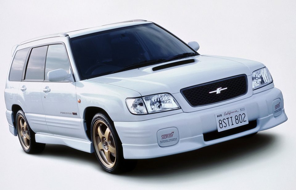
Руководство владельца Subaru Forester I (SF) — файл pdf
disk.yandex.ru/i/DtLIPRMqvXHX4g
Руководство по сервисному обслуживанию Subaru Forester I (SF) 1997-2001 MY — zip-архив
(Мультимедийная книга Subaru Forester с 1997 г.)
disk.yandex.ru/d/2LtfvY0NzRmzww
Subaru Forester с 1997 г. выпуска. Устройство Обслуживание Ремонт (Переработанное издание) — файл pdf
drive.google.com/file/d/0…4WWNjQzg/view?usp=sharing
+++++++++++++++++++++++++++++++++++++++++++++++
Руководство по техническому обслуживанию Subaru Forester II (SG) 2004 MY — файл pdf
yadi.sk/i/NKxH1DR4m68Wzg
Руководство по эксплуатации Subaru Forester II (SG) 2005 MY — файл pdf
drive.google.com/file/d/0…5MHJmYlk/view?usp=sharing
Руководство по эксплуатации Subaru Forester II (SG) 2007 MY — файл pdf
drive.google.com/file/d/0…zdi1Cb0E/view?usp=sharing
Руководство по обслуживанию Subaru Forester II (SG) 2008 MY — файл pdf
drive.google.com/file/d/0…5ell0MDg/view?usp=sharing
+++++++++++++++++++++++++++++++++++++++++++++++
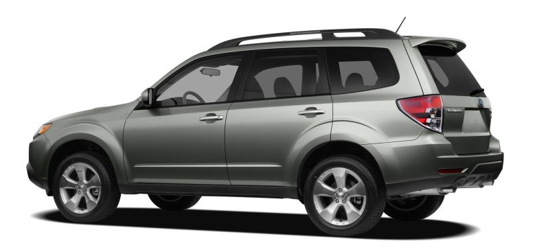
Руководство по ремонту и эксплуатации Subaru Forester III (SH) 2009 MY — файл pdf
drive.google.com/file/d/0…SUkVMT2M/view?usp=sharing
Руководство по сервисному обслуживанию Subaru Forester III (SH) 2009 MY — сжатый архив
disk.yandex.ru/d/B96-Gk7pODUIYQ
drive.google.com/file/d/0…PR21RT2c/view?usp=sharing
Руководство по сервисному обслуживанию Subaru Forester III (SH) 2012 MY — zip-архив
yadi.sk/d/WyoA6UE8prtNW
+++++++++++++++++++++++++++++++++++++++++++++++
Руководство по сервисному обслуживанию Subaru Forester IV (SJ) 2014 MY — zip-архив
drive.google.com/file/d/0…ydE1vTEk/view?usp=sharing
или
disk.yandex.ru/d/ZmJB58ifGLEsRg
Руководство по эксплуатации Subaru Forester IV (SJ) 2014 MY — файл pdf
drive.google.com/file/d/0…kM1dnS00/view?usp=sharing
+++++++++++++++++++++++++++++++++++++++++++++++
Руководство по обслуживанию и ремонту Subaru Forester SK (SM G8240GR FORESTER 19MY, версия 002) — файл ISO в rar-архиве.
yadi.sk/d/nnaihovx9Le_dQ или drive.google.com/file/d/1…_mFo-IS9/view?usp=sharing
Взято здесь cloud.mail.ru/public/HRZT/mfMRZ48dH
Руководство по эксплуатации Subaru Forester V (SK) 2019 MY — файл pdf
yadi.sk/i/H3Eh8Lm1IYQYgA
Краткое руководство по эксплуатации Subaru Forester V (SK) 2019 MY — файл pdf
yadi.sk/i/Fe1V-7hYZE59pA
Eyesight Руководство SK — файл pdf
yadi.sk/i/hZXPw5enDtoTqw
Starlink Руководство SK — файл pdf
yadi.sk/i/yDhy1Qx86FDbbg
+++++++++++++++++++++++++++++++++++++++++++++++
+++++++++++++++++++++++++++++++++++++++++++++++
Инструкция по эксплуатации автомобиля Subaru Forester 2005 модельного года (SG) — файл pdf
drive.google.com/file/d/0…BZkhGTEU/view?usp=sharing
Инструкция по эксплуатации автомобиля Subaru Forester 2007 модельного года (SG) — файл pdf
drive.google.com/file/d/0…SMzFxSHc/view?usp=sharing
Инструкция по эксплуатации автомобиля Subaru Forester 2011 модельного года (SH) — файл pdf drive.google.com/file/d/0…Ib0lEbm8/view?usp=sharing
Инструкция по эксплуатации автомобиля Subaru Forester 2012 модельного года (SH) — файл pdf drive.google.com/file/d/0…0cEE1bDg/view?usp=sharing
Инструкция по эксплуатации автомобиля Subaru Forester 2013 модельного года (SJ) — файл pdf drive.google.com/file/d/0…LZEgxbGM/view?usp=sharing
Инструкция по эксплуатации автомобиля Subaru Forester 2014 модельного года (SJ) — файл pdf drive.google.com/file/d/0…tOWt4elk/view?usp=sharing
Инструкция по эксплуатации автомобиля Subaru Forester 2015 модельного года (SJ) — файл pdf
drive.google.com/file/d/0…WZkI5SWs/view?usp=sharing
Инструкция по эксплуатации автомобиля Subaru Forester 2016 модельного года (SJ) — файл pdf
drive.google.com/file/d/0…kS3FSQVU/view?usp=sharing
+++++++++++++++++++++++++++++++++++++++++++++++
Subaru Forester Owner’s Manuals (ENG) — руководства по эксплуатации Subaru Forester на английском языке
Subaru Forester I (SF) 1998 Owner’s Manual ENG yadi.sk/d/OApC-oKBFMhGo
Subaru Forester I (SF) 1999 Owner’s Manual ENG yadi.sk/d/V6d3vPaGFMi5X
Subaru Forester I (SF) 2000 Owner’s Manual ENG yadi.sk/d/1Kb7E0RLFMiAS
Subaru Forester I (SF) 2001 Owner’s Manual ENG yadi.sk/d/OeuIrbH-FMiE2
Subaru Forester I (SF) 2002 Owner’s Manual ENG yadi.sk/d/7dlwPQT5FMiHm
Subaru Forester II (SG) 2003 Owner’s Manual ENG yadi.sk/d/8B5M3PEuFMiNv
Subaru Forester II (SG) 2004 Owner’s Manual ENG yadi.sk/d/DTiMBz4WFMiTP
Subaru Forester II (SG) 2005 Owner’s Manual ENG yadi.sk/d/tG-w1PzAFMiYG
Subaru Forester II (SG) 2006 Owner’s Manual ENG yadi.sk/d/h8RcBfgFFMic2
Subaru Forester II (SG) 2007 Owner’s Manual ENG yadi.sk/d/5heDeXV3FMifh
Subaru Forester II (SG) 2008 Owner’s Manual ENG yadi.sk/d/KTL_5eO7FMikE
Subaru Forester III (SH) 2009 Owner’s Manual ENG yadi.sk/d/CEPVhIngFMipG
Subaru Forester III (SH) 2010 Owner’s Manual ENG yadi.sk/d/Ee_eL7omFMiti
Subaru Forester III (SH) 2011 Owner’s Manual ENG yadi.sk/d/1Jacl7TMFMizz
Subaru Forester III (SH) 2012 Owner’s Manual ENG yadi.sk/d/44rqNMDzFMj7A
Subaru Forester IV (SJ) 2013 Owner’s Manual ENG yadi.sk/d/k40hjMB8FMjAd
Subaru Forester IV (SJ) 2014 Owner’s Manual ENG yadi.sk/d/mTlbnLRoFMjEX
Subaru Forester V (SK) 2019 Owner’s Manual ENG yadi.sk/d/8BgNvdXr5ryIxg
+++++++++++++++++++++++++++++++++++++++++++++++
Subaru Forester 2001 Service Manual ENG yadi.sk/d/PQ4ylgUpFNzot взято здесь manualov.net/Subaru.php
Subaru Forester 2003 Service Manual ENG — файл pdf yadi.sk/i/Yd-Gbfua3E38PH взято здесь
www.drive2.ru/l/466065937657758129/
Subaru Forester 2004 Service Manual ENG yadi.sk/d/_BMMdFxqFP28v взято здесь manualov.net/Subaru.php
Subaru Forester 2007 Service Manual (ENG) yadi.sk/d/B6rTskG3cxMbq взято здесь manualov.net/Subaru.php
Subaru Forester 2007 Service Manual ENG yadi.sk/d/X4CZKXSDcxMGW взято здесь auto-b.ru/blog/Subaru/2065.html
Subaru Forester IV (SJ) 2014 MY Service Manual (ENG) yadi.sk/d/zl1LmYEebjUsr + дополнение по ремонту кузова yadi.sk/d/hcob_9VJBQkDZ
пароль к архивам: forestermoscowclub взято здесь forester-moscowclub.ru/showthread.php?p=694911
+++++++++++++++++++++++++++++++++++++++++++++++
Схемы электропроводки:
Subaru Forester I (SF) 1998 Wires Diagram Section (EN) Электросхемы дорестайл SF — файлы pdf в архиве
yadi.sk/d/aCZSAQ2GqQQxT или
drive.google.com/file/d/1…ziEs-HcU/view?usp=sharing
Subaru Forester I (SF) 2001 Wires Diagram Section (EN) Электросхемы рестайл SF — файлы pdf в архиве
yadi.sk/d/f7GjJ6MIqQR3m
Схема электропроводки Subaru Forester SG 02-05 дорестайл Русский мануал — файл pdf
yadi.sk/i/daoWHmQ_qQQW7 или
drive.google.com/file/d/0…d1jolSTlJMVlJZFMwMW8/view
Схема электропроводки Subaru Forester SG 06-08 рестайл Русский мануал — файл pdf
yadi.sk/i/LfAHumyGqQQWD
+++++++++++++++++++++++++++++++++++++++++++++++
Мануалы и аксессуары для других Subaru (cпасибо tarasusNN): здесь.
+++++++++++++++++++++++++++++++++++++++++++++++
Полный размер

Полный размер
<Данный способ связи не предназначен для предъявления требований, предусмотренных статьями 18, 19 Закона РФ от 07.02.1992 N 2300-1 «О защите прав потребителей».
При возникновении данных требований, просьба обращаться письменно по адресу: 115280, город Москва, улица Автозаводская, дом 21А, этаж 2 ООО «Субару Мотор».
Для корректной доставки письма объем вложений не должен превышать 10 Мб.
Foreword
Congratulations on choosing a SUBARU vehicle. This Owner’s
Manual has all the information necessary to keep your SUBARU in
excellent condition and to properly maintain the emission control
system for minimizing emission pollutants. We urge you to read
this manual carefully so that you may understand your vehicle and
its operation. For information not found in this Owner’s Manual,
such as details concerning repairs or adjustments, please contact
the SUBARU dealer from whom you purchased your SUBARU or
the nearest SUBARU dealer.
The information, specifi cations and illustrations found in this
manual are those in effect at the time of printing. FUJI HEAVY
INDUSTRIES LTD. reserves the right to change specifications and
designs at any time without prior notice and without incurring any
obligation to make the same or similar changes on vehicles
previously sold. This Owner’s Manual applies to all models and
covers all equipment, including factory installed options. Some
explanations, therefore may be for equipment not installed in your
vehicle.
Please leave this manual in the vehicle at the time of resale. The
next owner will need the information found herein.
FUJI HEAVY INDUSTRIES LTD., TOKYO, JAPAN
is a registered trademark of FUJI HEAVY INDUSTRIES LTD.
*
C
Copyright 2010 FUJI HEAVY INDUSTRIES LTD.
- Manuals
- Brands
- Subaru Manuals
- Automobile
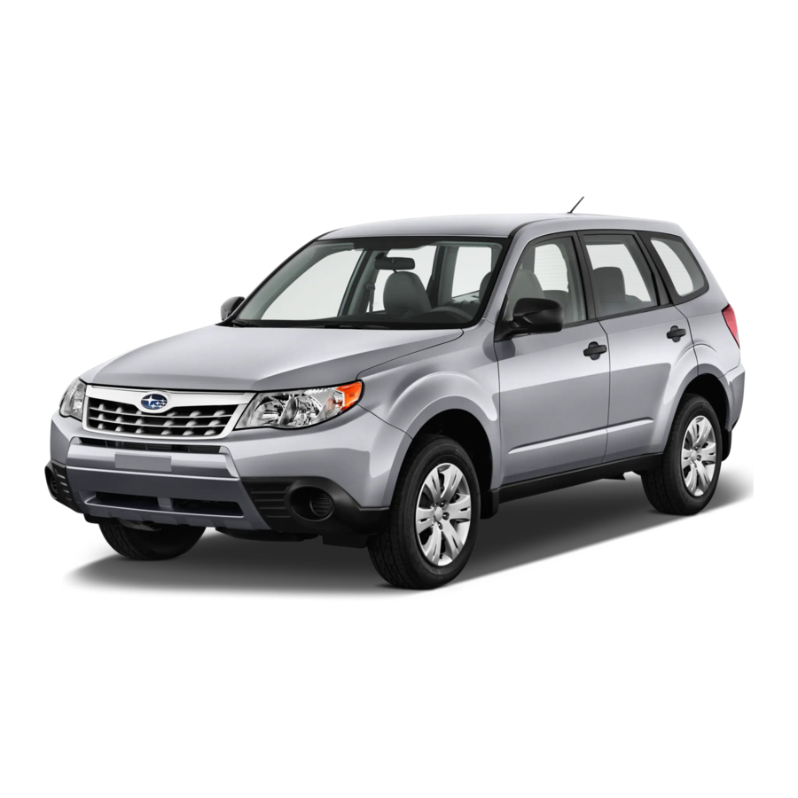
- 2011 Forester
- Quick reference manual
-
Contents
-
Table of Contents
-
Bookmarks
Related Manuals for Subaru 2011 Forester
Summary of Contents for Subaru 2011 Forester
-
Page 1
Forester 2011 Quick Reference Guide. I n f o r ma t i o n P r o v i d e d b y :… -
Page 2
All rights reserved. Contents may not be reprinted or electronically reproduced in whole or in part without prior written approval of Subaru of America, Inc. © 2010 Subaru of America, Inc. I n f o r ma t i o n P r o v i d e d b y :… -
Page 3
I n f o r ma t i o n P r o v i d e d b y :… -
Page 4
Table of Contents Getting Started 2 — 3 Instrument Panel 4 — 5 Gauges 6 — 9 Personalize 10 — 11 Controls 12 — 27 While Operating 28 — 29 Safety/In Case of Emergency 30 — 31 Additional Information 32 — 33 I n f o r ma t i o n P r o v i d e d b y :… -
Page 5: Remote Keyless Entry
Remote Keyless Entry Lock/Arm Unlock/Disarm • Press to lock all doors and • Press once to unlock the rear gate. driver’s door. • If any of the doors or the rear • Press twice (within five gate are not fully closed, an seconds) to unlock all doors.
-
Page 6: Heated Seats
Seating Heated Seats 10-Way Power Driver’s Seat (if equipped) (if equipped) Press the switch in the 1. Forward/Backward, Angle and Height Move the switch toward the front or rear to move corresponding direction for the desired seat temperature. the seat forward or backward. Pull the switch up To turn off the seat heater, or push down on the front of the switch to adjust slightly press in the opposite…
-
Page 7: Instrument Panel
Instrument Panel I n f o r ma t i o n P r o v i d e d b y :…
-
Page 8
14-19 20-25 Clock Press the “+” button to advance time or the “–” button to reverse the time. Vehicles with a navigation system please refer to the separate “Operating Instructions for Navigation System.” I n f o r ma t i o n P r o v i d e d b y :… -
Page 9
Gauges Immediate Attention Caution Informational Tachometer Speedometer Forester 2.5X Forester 2.5X Premium Forester 2.5X Limited Seatbelt warning Brake system Front passenger Hot coolant temperature / seatbelt warning Cold coolant temperature SRS airbag system High beam indicator light AT OIL TEMP Security indicator light (AT models) ABS warning… -
Page 10
Trip meter and odometer Fuel Gauge Trip meter A/B selection and trip meter reset knob Vehicle Dynamics Control/Vehicle Dynamics Turn signals Control operation Front fog light indicator Vehicle Dynamics Control OFF light (if equipped) CHECK ENGINE / Headlight indicator light Malfunction indicator SPORT mode Tire pressure warning light… -
Page 11
Gauges Immediate Attention Caution Informational Tachometer Forester 2.5X Touring Forester 2.5XT Touring Temperature Gauge Trip meter A/B selection and trip meter reset knob Fuel Gauge Seatbelt warning Brake system Front passenger High beam indicator light seatbelt warning Automatic headlight beam SRS airbag system leveler warning AT OIL TEMP… -
Page 12
Speedometer Trip meter and odometer Information display switching knob ECO Gauge Vehicle Dynamics Turn signals Control/Vehicle Dynamics Control operation Front fog light indicator Vehicle Dynamics Control OFF light (if equipped) CHECK ENGINE / Headlight indicator light Malfunction indicator SPORT mode Tire pressure warning light (AT models) Cruise control… -
Page 13: Steering Column
Personalize Tilt and Telescopic Steering Column Push the lever down firmly to adjust the vertical and lengthwise position of the column; firmly push the lever back up to lock the column in place. Do not adjust while driving. Power Exterior Mirrors Push the mirror selection switch to the “L”…
-
Page 14: Power Moonroof
Power Moonroof (if equipped) With the moonroof in the fully closed position, press the switch to fully open the moonroof. Press the switch to close the moonroof. To stop the moonroof in a midway position while opening or closing, momentarily press the switch to the side or side.
-
Page 15: Light Controls
Controls Light Controls Push up for right turn signal. Turns on headlights, instrument panel illumination, front side marker lights, taillights and license plate lights. Turns on fog lights (if equipped). Push down for left turn signal. Turns on instrument panel lights, tail lights, front side marker lights and license plate lights.
-
Page 16: Windshield Wipers
INT. HIGH Windshield Wipers To turn on the wipers, press the wiper control lever down one level for intermittent, two levels for low, or three levels for high speed. Return the lever to the “OFF” position to stop the wipers. For a single wipe move the lever up. To spray washer fluid, pull and hold the lever toward you.
-
Page 17: Manual Climate Control
Controls Manual Climate Control (if equipped) 1. Temperature Control Dial 3. Recirculated / Outside Air Button Rotate the temperature control dial from Press the air inlet selection button to blue for cool, to red for warm. prevent outside air from being drawn into the passenger compartment.
-
Page 18
Defrost / Defog 5. Rear Window Defogger Button To clear the windshield and front door Press the rear window defogger button windows of fog or frost, rotate the air to turn on the defogger. The defogger flow control dial to the defrost position, will automatically shut off after about set the temperature control to the red 15 minutes. -
Page 19: Automatic Climate Control
Controls Automatic Climate Control (if equipped) 2. Rear Window Defogger Button 1. Air Flow Control Dial Press the rear window defogger button On the automatic setting, the system to turn on the defogger. The defogger determines the air flow location to achieve will automatically shut off after about 15 the desired temperature or you can minutes.
-
Page 20
4. Air Conditioning Button the compartment. TO PREVENT Press the “A/C” button to activate the WINDSHIELD FOGGING, DO NOT air conditioning. Press it again to turn REMAIN IN THE RECIRCULATED off the air conditioning. MODE FOR AN EXTENDED PERIOD OF TIME. 5. -
Page 21
Controls Automatic Climate Control (if equipped) settings can be made for the driver’s side 1. Automatic On and Off and passenger’s side by adjusting the This system automatically controls dials appropriately. outlet air temperature, fan speed, air flow distribution, air inlet control, and air Operation in Manual Mode conditioner compressor operation. -
Page 22
4. Fan Speed Control Buttons 7. Air Conditioner Button Press the fan speed control buttons Press the “A/C” button to activate the to select seven different fan air conditioning. Press it again to turn speed positions. off the air conditioning. 5. -
Page 23: Radio Functions
Controls AM/FM Stereo with Single Disc CD/MP3/WMA Player (if equipped) Radio Functions 5. Seek 1. Power / Volume Control Press the right or left arrow of the “SEEK” Press the power / volume control knob button to pick up the next highest or for on or off;…
-
Page 24
CD Player Functions 14. Scan 8. Load Press the “SCAN” button to begin Insert a disc into the slot. The CD previewing the first 10 seconds will automatically be drawn in and of each track on the disc. Normal will begin play at the first track. playback will resume after all 9. -
Page 25
Controls AM/FM Stereo with Single Disc CD/MP3/WMA Player (if equipped) Radio Functions 1. Power / Volume Control 5. Seek Press the power / volume control knob Press the right or left arrow of the “SEEK” for on or off; rotate the knob to control button to pick up the next highest or lowest frequency. -
Page 26
8. PTY / CAT 14. Fast Forward / Fast Reverse Press the right arrow of the Press the “PTY/CAT” button to “SEEK” button for more than one change to program type selection second to fast forward. Release mode. The PTY group that you are the button to stop. -
Page 27
Controls AM/FM Stereo, HD Radio™ with Single Disc CD/MP3/ WMA Player (if equipped) Radio Functions 1. Power / Volume Control 5. Seek Press the power / volume control knob Press the right or left arrow of the “SEEK” for on or off; rotate the knob to control button to pick up the next highest or lowest frequency. -
Page 28
8. PTY / CAT 15. Forward / Reverse Press the “LIST” button to change Rotate the “TUNE/TRACK/ to program type selection mode. CH” knob clockwise to skip to The PTY group that you are the beginning of the next track; currently listening to is displayed rotate the knob counterclockwise for 10 seconds. -
Page 29: Aux Jack
Controls Steering Wheel Audio Controls (if equipped) • Press the “+” button to • Press the button to select the increase the volume. desired audio mode – FM, Press the “-” button to AM, SAT, CD, AUX, MEDIA. reduce the volume. •…
-
Page 30
Cruise Control • To activate the cruise control, press the • To resume your speed after “CRUISE” button. The “CRUISE” indicator canceling, press the “RES/ light on the instrument panel will turn on. ACC” button. To quit cruise control, press the “CRUISE” button again. -
Page 31: While Operating
While Operating Vehicle Dynamics Control OFF Switch Pressing the switch to deactivate the Vehicle Dynamics Control system can help in the following situations: • A standing start on a steeply sloping road with a snowy, gravel-covered, or otherwise slippery surface. •…
-
Page 32
Automatic Transmission Shift Mode 4-Speed Automatic Transmission with SPORTSHIFT Manual Control ® The automatic transmission gives you ultimate control with three different driving modes: Normal Mode, Sport Mode and Manual Mode. Normal Mode When the selector lever is in the “D” (Drive) position, the transmission is in Normal shift mode. -
Page 33: Child Restraint System
Safety / In Case of Emergency Child Restraint System For maximum safety, first carefully read the LATCH system instructions from the device manufacturer, as well as the installation instructions in your Owner’s Manual, to properly install the LATCH compatible restraint system. Use the appropriate seatbelts or anchorages provided in your vehicle.
-
Page 34
AWD system. A flatbed truck is the only recommended way to properly transport your AWD vehicle. If towing is necessary, it is best done by your Subaru dealer or a commercial towing service. Subaru Roadside Assistance Subaru Roadside Assistance is free and standard on every 2011 Subaru vehicle. -
Page 35: Additional Information
Subaru ownership. Log on to My.Subaru.com to access features such as: automated service history, e-mail maintenance reminders, online Owner’s Manual, warranty information, maintenance schedules and much more…
-
Page 36: Engine Oil
Fuel • 2.5 L DOHC Non-turbo models use regular unleaded gasoline with an octane rating of 87 AKI or higher. • 2.5 L DOHC Turbo models use premium unleaded gasoline with an octane rating of 91 AKI or higher. Fuel Capacity •…
-
Page 37
Notes I n f o r ma t i o n P r o v i d e d b y :… -
Page 38
Notes I n f o r ma t i o n P r o v i d e d b y :… -
Page 39
Notes I n f o r ma t i o n P r o v i d e d b y :… -
Page 40
Subaru of America, Inc., Subaru Plaza, P.O. Box 6000, Cherry Hill, NJ 08034-6000 MSA5B1104A Printed in USA 11/10 Issued 09/10 I n f o r ma t i o n P r o v i d e d b y :… -
Page 41: Owner Information
DELIVERY DATE OWNER NAME OWNER NAME Owner Resources & Warranty Present the Subaru Owner’s Manual & Quick Reference Guide (detailed review in “Operation & Controls” section) Review Subaru Roadside Assistance, Owner Cards & Provide Toll-Free Number 1-800-261-2155 Explain 3/36 BASIC Warranty / 5/60 Powertrain Warranty / Explain Wear Items &…
-
Page 42
Operation & Controls Please use & reference the SUBARU OWNER’S MANUAl & QUICK REfERENCE GUIDE OPERAtION & CONtROlS Review Master & Valet Keys Show Yellow Caps & Explain Checking & Filling of Vehicle Fluids Show Keyless Entry, Alarm System & Remote Start (if equipped) Show Fuel Filler Door &… -
Page 43
2011 Consumer Electronics/ Bluetooth & Audio Technology ® I n f o r ma t i o n P r o v i d e d b y : 793593_11a_Bluetooth_QRG_072310.indd 2 7/23/10 11:20 AM… -
Page 44
Table of Contents Bluetooth Basics 2 — 3 Bluetooth without 4 — 7 Navigation System Bluetooth with Harmon Kardon Audio System 8 — 11 BlueConnect ® 12 — 13 Bluetooth with Navigation System 14 — 21 Media Hub 22 -24 I n f o r ma t i o n P r o v i d e d b y : 793593_11a_Bluetooth_QRG_072310.indd 1 7/23/10 11:20 AM… -
Page 45
Bluetooth Basics • The Hands-free system may not operate properly under the following conditions: o The cell phone is turned off. o The cell phone is not connected to the Hands-free system. o The cell phone is not in the phone call area. o The battery of the cell phone has run down. -
Page 46
• Do not speak at the same time as the other party during a call. If you and the other party speak at the same time, it may be difficult for the other party to hear your voice and vice versa. This is normal. •… -
Page 47
Bluetooth without Navigation System (Impreza) Phone off Phone on Talk button hook button hook button Pairing Your Cell Phone Press the phone off hook button and listen to phone prompts. Press the talk button and name your phone. I n f o r ma t i o n P r o v i d e d b y : 793593_11a_Bluetooth_QRG_072310.indd 4 7/23/10 11:20 AM… -
Page 48
Press the talk button and say “confirm.” Pass-key will be given audibly as well as be displayed on the radio display. Put your phone into Bluetooth pairing mode and pair your phone to the system using the pass-key provided. When phone is successfully paired you will hear “The phone is paired and ready for use.”… -
Page 49: Making A Call
Making a Call Press phone off hook button. Press the talk button then say “Dial by number.” Press the talk button again and say the number. I n f o r ma t i o n P r o v i d e d b y : 793593_11a_Bluetooth_QRG_072310.indd 6 7/23/10 11:21 AM…
-
Page 50: Receiving A Call
Press the off hook button to dial or press the talk button to add more numbers. The phone will start dialing. To end the call, press the phone on hook button. Receiving a Call When a call comes in you will be notified. The audio system will mute and a voice prompt will inform you.
-
Page 51: Audio System
Bluetooth with Harmon Kardon Audio System (Legacy and Outback) Phone off Phone on Talk button hook button hook button Pairing Your Cell Phone Press the phone off hook button and listen to phone prompts. Press the talk button and name your phone. I n f o r ma t i o n P r o v i d e d b y : 793593_11a_Bluetooth_QRG_072310.indd 8 7/23/10 11:21 AM…
-
Page 52
Press the talk button and say “confirm.” Pass-key will be given audibly as well as be displayed on the radio display. Put your phone into Bluetooth pairing mode and pair your phone to the system using the pass-key provided. When phone is successfully paired you will hear “The phone is paired and ready for use.”… -
Page 53
Making a Call Press phone off hook button. Press the talk button then say “Dial by number.” Press the talk button again and say the number. I n f o r ma t i o n P r o v i d e d b y : 793593_11a_Bluetooth_QRG_072310.indd 10 7/23/10 11:21 AM… -
Page 54
The system will audibly repeat the number. If correct, press the off hook button to dial, or press the talk button to change, cancel or delete the number. The phone will start dialing. To end the call, press the phone on hook button. Receiving a Call When a call comes in you will be notified. -
Page 55
BlueConnect ® (Genuine Subaru accessory, standard on Tribeca 3.6R Limited and Touring models) Controls Location BlueConnect controls for the Legacy, Outback, Forester and Impreza are located in the center stack (Legacy shown). BlueConnect controls for the Tribeca are located in the overhead console. -
Page 56
Pairing Your Cell Phone • Press the phone button, the blue L.E.D. will glow and “Call” will be displayed. Listen to all options. • Say “setup”; then listen to all options. • Say “pairing options”; then listen to all options. •… -
Page 57
Bluetooth with Navigation System (Forester and Impreza) Microphone located in overhead console MENU button Pairing Your Cell Phone Press the MENU button; then touch the “Phone” soft key on the touch screen. Then touch “Bluetooth Settings.” I n f o r ma t i o n P r o v i d e d b y : 793593_11a_Bluetooth_QRG_072310.indd 14 7/23/10 11:22 AM… -
Page 58
Now touch “Register.” A pass-key number will appear on the screen. Put your phone into Bluetooth pairing mode and pair your phone to the system using the pass-key provided. When the phone is successfully paired the screen will show the phone’s name on the list. -
Page 59
Making a Call Press the MENU button; then touch the “Phone” soft key on the touch screen. Then touch “Bluetooth Phone”; a numeric keypad will be displayed. Touch the numbers for the phone number you wish to call. When complete, touch the green phone soft key. -
Page 60: During A Call
A confirmation screen will appear, touch “Yes” to make the call. During a Call Mute – Touch this to mute the call. Speaker – Touch this to switch the phone conversation back to your cell phone. Red phone symbol – Touch this to end a call.
-
Page 61
Bluetooth with Navigation System (Legacy and Outback) Microphone located next to the audio system MENU button Phone off Phone on Talk button hook button hook button I n f o r ma t i o n P r o v i d e d b y : 793593_11a_Bluetooth_QRG_072310.indd 18 7/23/10 11:23 AM… -
Page 62
Pairing Your Cell Phone Press the MENU button; then touch the “Phone” soft key on the touch screen. Then touch “Bluetooth Settings.” Now touch “Register.” A pass-key number will appear on the screen. I n f o r ma t i o n P r o v i d e d b y : 793593_11a_Bluetooth_QRG_072310.indd 19 7/23/10 11:23 AM… -
Page 63
Put your phone into Bluetooth pairing mode and pair your phone to the system using the pass-key provided. When the phone is successfully paired the screen will show the phone’s name on the list. Making a Call Press the Talk button on the steering wheel; then say “Dial by number.” A numerical keypad will be displayed. -
Page 64
During a Call Mute – Touch this to mute the call. Speaker – Touch this to switch the phone conversation back to your cell phone. Red phone symbol – Touch this to end a call. 1 – 5 – Touch 1 through 5 to change the volume of the call. -
Page 65: Media Hub
3. Activate the Bluetooth on the device. 4. Use the search for new device function on the device until the Media hub (“SUBARU”) is found. 5. Initiate pairing by the phone or device. 6. Enter the pas-key. I n f o r ma t i o n P r o v i d e d b y : 793593_11a_Bluetooth_QRG_072310.indd 22…
-
Page 66
Accessing the Media Hub To access an item connected to the Media hub press the SAT button located on the audio system repeatedly until the correct Media hub mode is selected. iPod Operation Text Display Press the TEXT button located on the audio system repeatedly to cycle through the available text fields: •… -
Page 67
USB Device Operation Text Display Press the TEXT button located on the audio system repeatedly to cycle through the available text fields: • TITLE – Song title • NAME – Artist — Album • CATEGORY – Displays the information related to the selected mode •… -
Page 68
Quick Reference Guide was accurate at the time of publication. We reserve the right to change features, operation and/or functionality of any vehicle specification at any time. Your Subaru dealer is the best source for the most current information. For detailed operating and safety information, please consult your Owner’s Manual. -
Page 69
SUBARU Owner’s Manual Supplement for Forester (Non-turbo models) Please refer to the separate Owner’s Manual for information not covered on this supplement page. Please keep this supplement with your Owner’s Manual and leave it in the vehicle at the time of resale. The next owner will need the information it contains. -
Page 70
2011MY SUBARU FORESTER Owner’s Manual Supplement Updated Oil Filter Information Please refer to your 2011MY Forester Owner’s Manual for information not covered in this supplement. Please keep this supplement with your Owner’s Manual, and leave it in the vehicle at the time of resale. The next owner will need the information it contains. -
Page 71
Foreword Congratulations on choosing a SUBARU vehicle. This Owner’s Manual has all the information necessary to keep your SUBARU in excellent condition and to properly maintain the emission control system for minimizing emission pollutants. We urge you to read this manual carefully so that you may understand your vehicle and its operation. -
Page 72
This manual describes the following vehicle types.* * The illustrated vehicle is one of the FORESTER series. -
Page 74: Models With Hid Headlights
& Using your Owner’s Manual All SUBARU vehicles distributed by High Intensity Discharge (HID) head- Subaru of America, Inc. and sold at retail Before you operate your vehicle, carefully lights contain mercury. For that by an authorized SUBARU dealer in the read this manual.
-
Page 75: Safety Warnings
Chapter 10: Appearance care fully in order to gain a better understand- This chapter informs you how to keep your ing of how to use your SUBARU vehicle SUBARU looking good. safely. Chapter 11: Maintenance and service…
-
Page 76: Abbreviation List
& Abbreviation list Vehicle symbols Abbreviation Meaning You will find several abbreviations in this Lower anchors and tethers for There are some of the symbols you may LATCH manual. The meanings of the abbrevia- children see on your vehicle. tions are shown in the following list. Light emitting diode For warning and indicator lights, refer to “Warning and indicator lights”…
-
Page 77
Mark Name Mark Name Mark Name Rear window defogger/Out- Hazard warning flasher Lights side mirror defogger Tail lights, license plate light Engine hood and instrument panel illumi- Air recirculation nation Seat heater Engine oil Headlights Child restraint top tether an- Washer Turn signal chorages… -
Page 78: Child Safety
& Child safety . The SRS airbags deploy with Safety precautions when considerable speed and force. driving Occupants who are out of proper WARNING & Seatbelt and SRS airbag position when the SRS airbag . Never hold a child on your lap or deploys could suffer very serious injuries.
-
Page 79
. Never leave unattended children The SRS airbag deploys with gine exhaust system to prevent considerable speed and force in the vehicle. They could acci- engine exhaust gas from enter- and can injure or even kill chil- dentally injure themselves or ing the vehicle. -
Page 80: Drinking And Driving
& Drinking and driving & Drugs and driving & Driving when tired or sleepy WARNING WARNING WARNING Drinking and then driving is very There are some drugs (over the When you are tired or sleepy, your dangerous. Alcohol in the blood- counter and prescription) that can reaction time will be delayed and stream delays your reaction time…
-
Page 81: Driving With Pets
Your vehicle should not be modified unrestrained pets or cages can be thrown journey. other than with genuine SUBARU around inside the vehicle and hurt you or Check the tire pressure when the tires are parts and accessories. Other types your passengers.
-
Page 82: California Proposition 65
& California proposition 65 & On-road and off-road driving General information warning This vehicle is classified as a utility & Noise from under the vehicle vehicle. Utility vehicles have a significantly WARNING higher rollover rate than other types of NOTE vehicles.
-
Page 83
— — — — — — — — — — — — — — — — — — — — — — — — — — — — — — — — — — — — — — — — —… -
Page 84: Table Of Contents
Table of contents Seat, seatbelt and SRS airbags Keys and doors Instruments and controls Climate control Audio Interior equipment Starting and operating Driving tips In case of emergency Appearance care Maintenance and service Specifications Consumer information and Reporting safety defects Index…
-
Page 85
Engine hood (page 11-5) Illustrated index Headlight switch (page 3-30) & Exterior Replacing bulbs (page 11-47) Wiper switch (page 3-34) Moonroof (page 2-25) Roof rail (page 8-14) Door locks (page 2-4) Tire pressure (page 11-33) Flat tires (page 9-6) 10) Tire chains (page 8-11) 11) Front fog light switch (page 3-32) 12) Tie-down hooks (page 9-14) 13) Towing hook (page 9-14) -
Page 86
Rear window defogger button (page 3-45) Fuel filler lid and cap (page 7-3) Child safety locks (page 2-20) Tie-down hook (page 9-14) Rear gate (page 2-23) Towing hook (page 9-14) – CONTINUED –… -
Page 87
& Interior Lower anchorages for child restraint system (page 1-29) ! Passenger compartment area Seatbelt (page 1-12) Parking brake lever (page 7-29) Front seat (page 1-2) Rear seat (page 1-7) -
Page 88
Center console (page 6-5) Cup holder (page 6-8) Front power supply socket (page 6-9) Glove box (page 6-5) – CONTINUED –… -
Page 89
& Instrument panel Door locks (page 2-4) Outside mirror switch (page 3-44) Illumination brightness control (page 3-32) Light control lever (page 3-29) Combination meter (page 3-6) Wiper control lever (page 3-33) Hazard warning flasher switch (page 3-5) Audio (page 5-1) Shift lever (MT) (page 7-13)/ Select lever (AT) (page 7-15) 10) Climate control (page 4-1) -
Page 90
& Light control and wiper control levers/switches Windshield wiper (page 3-34) Mist (page 3-35) Windshield washer (page 3-35) Rear window wiper and washer switch (page 3-36) Wiper intermittent time control switch (page 3-35) Wiper control lever (page 3-33) Light control switch (page 3-29) Fog light switch (page 3-32) Headlight ON/OFF (page 3-30) 10) Headlight flasher High/Low beam… -
Page 91: Combination Meter
& Combination meter Tachometer (page 3-10) Trip meter and odometer (page 3-8) ! Type A Select lever and gear position indicator (page 3-24) Speedometer (page 3-8) Information display switching knob (page 3-26) ECO gauge (page 3-12) Fuel gauge (page 3-10) Temperature gauge (page 3-11) Trip meter A/B selection and trip meter reset knob (page 3-6)
-
Page 92
! Type B (U.S.-spec. models) Tachometer (page 3-10) Speedometer (page 3-8) Fuel gauge (page 3-10) Trip meter A/B selection and trip meter reset knob (page 3-6) Odometer/Trip meter (page 3-8) Select lever and gear position indicator (AT models) (page 3-24) Coolant temperature low indicator light/ Coolant temperature high warning light (page 3-16) -
Page 93
! Type B (except U.S.-spec. models) Tachometer (page 3-10) Speedometer (page 3-8) Fuel gauge (page 3-10) Trip meter A/B selection and trip meter reset knob (page 3-6) Odometer/Trip meter (page 3-8) Select lever and gear position indicator (AT models) (page 3-24) Coolant temperature low indicator light/ Coolant temperature high warning light (page 3-16) -
Page 94
& Warning and indicator lights Mark Name Page Mark Name Page Mark Name Page Front fog light indicator ABS warning light 3-19 3-25 light (if equipped) Seatbelt warning light 3-13 Brake system warning 3-20 Security indicator light 3-23 light Front passenger’s seat- 3-13 belt warning light Door open warning light… -
Page 95
Function settings A SUBARU dealer can change the settings of the functions shown in the following table to meet your personal requirements. Contact the nearest SUBARU dealer for details. If your vehicle is equipped with the genuine SUBARU navigation system, the settings for some of these functions can be changed using the navigation monitor. -
Page 96
Automatic/Emergency Locking Retractor window-side rear passengers……1-33 (A/ELR) …………1-13 SUBARU advanced frontal airbag system … 1-37 Seatbelt warning light and chime ……1-13 SRS side airbag and SRS curtain airbag….. 1-47 Fastening the seatbelt …….. -
Page 97: Seat, Seatbelt And Srs Airbags
Seat, seatbelt and SRS airbags Front seats If the front seatbacks are not used in the upright position in a collision, the risk of sliding under WARNING the lap belt and of the lap belt sliding up over the abdomen will .
-
Page 98: Manual Seat
Seat, seatbelt and SRS airbags & Manual seat ! Reclining the seatback restraint device or in a seatbelt, whichever is appropriate for the ! Forward and backward adjustment child’s age, height and weight. Se- cure ALL types of child restraint devices (including forward facing child seat) in the REAR seats at all times.
-
Page 99: Power Seat (Driver’s Seat — If Equipped)
Seat, seatbelt and SRS airbags & Power seat (driver’s seat – if ! Seat cushion height adjustment (driver’s seat) equipped) WARNING When the lever is pushed down, the seat To prevent the passenger from slid- is lowered. ing under the seatbelt in the event of When the lever is pulled up, the seat a collision, always put the seatback rises.
-
Page 100: Head Restraint Adjustment
Seat, seatbelt and SRS airbags justment of the seat, you cannot adjust Both the driver’s seat and the front WARNING the seat cushion angle or seat cushion passenger’s seat are equipped with head height. restraints. To prevent the passenger from slid- Seat cushion angle control switch The head restraint should be adjusted so ing under the seatbelt in the event of…
-
Page 101: Active Head Restraint
& Active head restraint to warn the persons concerned. rear-end collision, have an . Do not put anything on the seat authorized SUBARU dealer in- spect the active head restraints. which insulates against heat, . The active head restraints may such as a blanket, cushion, or similar items.
-
Page 102: Rear Seats
Seat, seatbelt and SRS airbags position. Rear seats To turn on the seat heater, press the “LO” or “HI” position on the switch, as desired, depending on the temperature. Selecting the “HI” position will cause the seat to heat up quicker. To turn off the seat heater, lightly press the opposite side of the current position.
-
Page 103: Armrest
Seat, seatbelt and SRS airbags & Armrest & Head restraint adjustment Both the rear window side seats and the rear center seat are equipped with head restraints. WARNING . Never drive the vehicle with the head restraints removed because they are designed to reduce the risk of serious neck injury in the event that the vehicle is struck from the rear.
-
Page 104
Seat, seatbelt and SRS airbags ! Rear windows side seating position position depending on your sitting height. Head restraint Release button Head restraint Release button To raise: When not used (retracted position) Pull the head restraint up. To remove: When used (click position) To lower: While pressing the release button, pull out the head restraint. -
Page 105: Reclining The Seatback (If Equipped)
1-10 Seat, seatbelt and SRS airbags appropriate position depending on your sliding under the lap belt and of the sitting height. When the rear center seat- lap belt sliding up over the abdomen ing position is not occupied, lower the will increase, and both can result in head restraint to improve rearward visibi- serious internal injury or death.
-
Page 106
1-11 Seat, seatbelt and SRS airbags ing down the rear seatback, re- to place all of the seatbelts and turn the rear seat center table to the tab attached to the seat cushion above the seat cushion. its original position. If the rear seat center table is not returned And make certain that the to its original position, the rear… -
Page 107: Seatbelts
1-12 Seat, seatbelt and SRS airbags Seatbelts the rear seat properly restrained According to accident statistics, at all times. The SRS airbag children are safer when properly & Seatbelt safety tips deploys with considerable speed restrained in the rear seating positions than in the front seat- and force and can injure or even kill children, especially if they are…
-
Page 108: Emergency Locking Retractor (Elr)
1-13 Seat, seatbelt and SRS airbags & Emergency Locking Retrac- tions only) and then if necessary move the Automatic Locking Retractor (ALR) mode. child closer to the belt buckle to help tor (ELR) When the child restraint system is re- provide a good shoulder belt fit.
-
Page 109
1-14 Seat, seatbelt and SRS airbags . Seatbelts provide maximum re- ! Front seatbelts straint when the occupant sits 1. Adjust the seat position according to well back and upright in the seat. the following procedure. To reduce the risk of sliding Driver’s seat: Adjust the seatback to the under the seatbelt in a collision, upright position. -
Page 110
1-15 Seat, seatbelt and SRS airbags ! Adjusting the front seat shoulder WARNING belt anchor height When wearing the seatbelts, make sure the shoulder portion of the webbing does not pass over your neck. If it does, adjust the seatbelt anchor to a lower position. -
Page 111
1-16 Seat, seatbelt and SRS airbags ! Rear seatbelts (except rear center Push the button on the buckle. seatbelt) Before closing the door, make sure that 1. Sit well back in the seat. the belts are retracted properly to avoid catching the belt webbing in the door. -
Page 112
1-17 Seat, seatbelt and SRS airbags The rear center seatbelt is stowed in a WARNING WARNING recessed compartment located in the ceiling above the cargo area. Fastening the seatbelt with the web- Be sure to fasten both tongue plates bing twisted can increase the risk or to the respective buckles. -
Page 113
1-18 Seat, seatbelt and SRS airbags 2. After drawing out the seatbelt, pass it 6. Place the lap belt as low as possible through the belt guide. on your hips, not on your waist. ! Unfastening the seatbelt 4. Insert the center seatbelt tongue plate into the center seatbelt buckle marked “CENTER”… -
Page 114: Seatbelt Maintenance
1-19 Seat, seatbelt and SRS airbags . Have the seatbelt fully rolled up You should hold the webbing end and guide it back into the retractor while it is so that the tongue plates are rolling up. Neatly store the tongue plate in neatly stored.
-
Page 115: Front Seatbelt Pretensioners
This smoke does not indicate a bly or surrounding area has been fire in the vehicle. damaged, contact your SUBARU dealer as soon as possible. Once the seatbelt pretensioner has been . When you sell your vehicle, we urge…
-
Page 116: System Monitors
Do not collision damage or for other Always consult your SUBARU dealer if use electrical test equipment on reasons, consult your SUBARU you want to install any accessory parts to any circuit related to the seatbelt dealer.
-
Page 117: Child Restraint Systems
1-22 Seat, seatbelt and SRS airbags properly secured in the vehicle. When Child restraint systems child from injury in a collision, installing the child restraint system, care- because the child will be caught fully follow the manufacturer’s instructions. between the passenger and objects inside the vehicle.
-
Page 118: Where To Place A Child Restraint System
(bars) are provided for WARNING straint system installing a child restraint system. The following are SUBARU’s recommen- Put children aged 12 and under in Some types of child restraints might not be dations on where to place a child restraint…
-
Page 119: Choosing A Child Restraint System
1-24 Seat, seatbelt and SRS airbags & Choosing a child restraint & Installing child restraint sys- cording to accident statistics, chil- dren are safer when properly re- system tems with A/ELR seatbelt strained in the rear seating posi- tions than in the front seating posi- WARNING tions.
-
Page 120
1-25 Seat, seatbelt and SRS airbags child suffering personal injury in the event of an accident may be in- creased. ! Installing a rearward facing child restraint 4. Take up the slack in the lap belt. 6. Push and pull the child restraint system forward and from side to side to 5. -
Page 121
1-26 Seat, seatbelt and SRS airbags NOTE When the child restraint system is no longer in use, remove it and restore the ELR function of the retractor. That function is restored by allowing the seatbelt to retract fully. ! Installing forward facing child re- straint 8. -
Page 122: Installing A Booster Seat
1-27 Seat, seatbelt and SRS airbags 9. To remove the child restraint system, press the release button on the seatbelt buckle and allow the belt to retract completely. The belt will return to the ELR mode. NOTE When the child restraint system is no longer in use, remove it and restore the ELR function of the retractor.
-
Page 123
1-28 Seat, seatbelt and SRS airbags 2. Run the lap and shoulder belt through injuries or death to the child. increase the risk or severity of or around the booster seat and the child injury to the child. following the instructions provided by its . -
Page 124: Installation Of Child Restraint Systems By Use Of Lower And Tether Anchorages (Latch)
1-29 Seat, seatbelt and SRS airbags & Installation of child restraint tight and secure, the danger of your systems by use of lower and child suffering personal injury in the event of an accident may be in- tether anchorages (LATCH) creased.
-
Page 125
1-30 Seat, seatbelt and SRS airbags the rear seat window-side seating posi- the seat cushion meets the seatback. tions. For each window-side seating posi- 1. Use the “ ” marks to locate the two tion, two lower anchorages are provided. lower anchorages (bars) for the position Each lower anchorage is located where where you want to install the child restraint… -
Page 126: Top Tether Anchorages
If you have any question concerning this belt. type of child restraint system, ask your 4. Connect the top tether hook to the SUBARU dealer. tether anchorage and firmly tighten the tether. For information on how to set the top tether, refer to “Top tether anchorages”…
-
Page 127
1-32 Seat, seatbelt and SRS airbags ! Anchorage location position. ! To hook the top tether 2. For both window-side seating posi- tions, remove the cover for the appropriate upper anchorage. 1. Remove the headrest at the window- side seating position where the child restraint system has been installed with the lower anchorages or seatbelt;… -
Page 128: Srs Airbag (Supplemental Restraint System Airbag)
1-33 Seat, seatbelt and SRS airbags Please contact your SUBARU dealer if *SRS airbag (Supplemental gers) you have any question regarding the Restraint System airbag) These SRS airbags are designed only installation of a child restraint system. as a supplement to the primary protec- *SRS: This stands for supplemental re- tion provided by the seatbelt.
-
Page 129
1-34 Seat, seatbelt and SRS airbags refer to “Seatbelts” F1-12. ment, the driver should always WARNING sit upright and well back in the . Do not sit or lean unnecessarily seat as far from the steering . Put children aged 12 and under in close to the SRS airbag. -
Page 130
1-35 Seat, seatbelt and SRS airbags positions than in the front seat- get fresh air promptly. ing positions. . A deploying SRS airbag releases For instructions and precautions hot gas. Occupants could get concerning the child restraint burned if they come into direct system, refer to “Child restraint contact with the hot gas. -
Page 131
1-36 Seat, seatbelt and SRS airbags ! Components Side airbag sensor (center pillar right- hand side) 10) Airbag wiring 11) Seatbelt pretensioner (driver’s side) 12) Seatbelt pretensioner (front passenger’s side) 13) Curtain airbag sensor (rear wheel house right-hand side) 14) Curtain airbag sensor (rear wheel house left-hand side) 15) Curtain airbag module (right side) 16) Curtain airbag module (left side) -
Page 132: Subaru Advanced Frontal Airbag System
TOO CLOSE TO THE SRS AIRBAG. The driver’s SRS frontal airbag is stowed in the center portion of the steering wheel. Your vehicle is equipped with a SUBARU The front passenger’s SRS frontal airbag advanced frontal airbag system that com-…
-
Page 133
1-38 Seat, seatbelt and SRS airbags seatbelt to help avoid injuries that can result when the SRS airbag contacts an occupant not in proper position such as one thrown toward the front of the vehicle during pre- accident braking. WARNING WARNING Never hold a child on your lap or in The SRS airbag deploys with con-… -
Page 134
For the adjustment procedure of of impact. Observe the following precautions. Failure the manual seats, refer to “Manual seat” to do so may prevent the SUBARU F1-3. Have the system inspected by your advanced frontal airbag system from SUBARU dealer immediately if the SRS… -
Page 135
REAR seat. This is . The seat is equipped with a forward system inspected by your SUBARU deal- because children sitting in the front er immediately if the SRS airbag system facing child restraint system and a small passenger’s seat may be killed or… -
Page 136
ON indicator illuminates and the Children who have outgrown a child contact your SUBARU dealer for an OFF indicator turns off even when an restraint system should always wear the inspection. -
Page 137
<Hawaii> Following the system check, both indica- Servco Subaru Inc., dba Subaru Hawaii ! If the passenger’s frontal airbag OFF tors turn off for 2 seconds. Now, the ON 2850 Pukoloa Street, Suite 202, Honolulu,… -
Page 138
1-43 Seat, seatbelt and SRS airbags ! Operation you bought your vehicle. Driver’s side Passenger’s side SRS AIRBAGs deploy as soon as a collision occurs. After deployment, SRS AIRBAGs start to deflate immediately so that the driver’s vision is not obstructed. -
Page 139
The time required from detect- The SUBARU advanced frontal airbag ing impact to the deflation of the SRS The driver’s SRS frontal airbag and front system is designed to determine the airbag after deployment is shorter than the passenger’s SRS frontal airbag are de-… -
Page 140
1-45 Seat, seatbelt and SRS airbags ! Example of accident in which the ! Examples of the types of accidents Only the driver’s SRS frontal airbag or both driver’s and front passenger’s SRS driver’s/driver’s and front passen- in which it is possible that the frontal airbags may be activated when the ger’s SRS frontal airbag(s) will most driver’s/driver’s and front passen-… -
Page 141
1-46 Seat, seatbelt and SRS airbags The vehicle strikes an object, such as a ! Examples of the types of accidents in which deployment of the driver’s/driver’s telephone pole or sign pole. and front passenger’s SRS frontal airbag(s) is unlikely to occur. The vehicle slides under the load bed of a truck. -
Page 142: Srs Side Airbag And Srs Curtain Airbag
1-47 Seat, seatbelt and SRS airbags ! Examples of the types of accidents & SRS side airbag and SRS to deploy if the vehicle is struck from the side or from behind, or if it rolls onto its in which the driver’s/driver’s and curtain airbag side or roof, or if it is involved in a low- front passenger’s SRS frontal…
-
Page 143
1-48 Seat, seatbelt and SRS airbags door, and it provides protection WARNING by deploying rapidly (faster than the blink of an eye) in the event of The SRS side airbag and SRS a side impact collision. However, curtain airbag are designed as only the force of SRS side airbag a supplement to the primary protec- deployment may cause injuries… -
Page 144
1-49 Seat, seatbelt and SRS airbags WARNING . Never allow a child to kneel on the front passenger’s seat facing the side window or to wrap his/ her arms around the front seat seatback. In the event of an accident, the force of the SRS side airbag deployment could injure the child seriously be- cause his/her head or arms or… -
Page 145
1-50 Seat, seatbelt and SRS airbags deploy independently of each other since A hands-free microphone or WARNING each has its own impact sensor. There- other accessory in such a loca- fore, they may not both deploy in the same tion could be propelled through Do not put any kind of cover or accident. -
Page 146
1-51 Seat, seatbelt and SRS airbags vehicle, the control module inflates the and inclination at the time of the rollover. After deployment, do not touch any curtain airbags. After the deployment, the part of the SRS curtain airbag ! Example of the type of accident in SRS side airbag immediately starts to system (from the front pillar to the which the SRS side airbag will most… -
Page 147
1-52 Seat, seatbelt and SRS airbags A severe side impact near the front seat ! Examples of the types of accidents in which the SRS curtain airbag will most or the rear seat activates the SRS curtain likely deploy. airbag. The vehicle rolls onto its side or the roof. -
Page 148
1-53 Seat, seatbelt and SRS airbags Hitting a curb, edge of pavement or hard ! Examples of the types of accidents in which it is possible that the SRS side surface airbag and the SRS curtain airbag will deploy. Falling into or jumping over a deep hole Landing hard or vehicle falling It is possible that the SRS side and curtain airbags will deploy if a serious impact… -
Page 149
1-54 Seat, seatbelt and SRS airbags The vehicle is involved in an oblique ! Examples of the types of accidents in which the SRS side airbag is unlikely to side-on impact. deploy. The vehicle is involved in a side-on impact in an area outside the vicinity of the passenger compartment. -
Page 150
1-55 Seat, seatbelt and SRS airbags The vehicle is involved in an oblique ! Examples of the types of accidents in which the SRS curtain airbag is unlikely side-on impact. to deploy. The vehicle is involved in a side-on impact in an area outside the vicinity of the passenger compartment. -
Page 151
1-56 Seat, seatbelt and SRS airbags The vehicle is struck from behind. ! Examples of the types of accidents and SRS curtain airbag are activated on the first impact, they will not be activated in which the SRS side airbag and The SRS side airbag and SRS curtain on the second. -
Page 152: Srs Airbag System Monitors
SRS airbag – Driver’s side system. Immediately take your vehi- – Front passenger’s side cle to your nearest SUBARU dealer . Curtain airbag sensor to have the system checked. Unless – Rear wheel house right-hand side checked and properly repaired, the seatbelt pretensioners and/or SRS –…
-
Page 153: Srs Airbag System Servicing
NOTE the work performed by an author- warning light In the following cases, contact your ized SUBARU dealer. The SRS air- . Illumination of the warning light SUBARU dealer as soon as possible. bag control module, impact sensors while driving .
-
Page 154: Precautions Against Vehicle Modification
SRS airbag system Always consult your SUBARU dealer if WARNING components and/or wiring is not you want to install any accessory parts on your vehicle.
-
Page 155
— — — — — — — — — — — — — — — — — — — — — — — — — — — — — — — — — — — — — — — — —… -
Page 156: Keys And Doors
Keys and doors Keys …………..Alarm system …………. 2-15 Key number plate ……….System operation……….2-15 Activating and deactivating the alarm system ..2-15 Immobilizer …………If you have accidentally triggered the alarm Security ID plate……….system …………2-16 Security indicator light ……..Arming the system ……….
-
Page 157: Keys
Keys and doors glove box locked when you leave your Keys Immobilizer vehicle and valet key at a parking facility. CAUTION CAUTION Do not attach a large key holder or FCC WARNING key case to either key. If it bangs Changes or modifications not ex- against your knees while you are pressly approved by the party re-…
-
Page 158: Security Id Plate
ID plate attached to the key set. Write the registration of keys with your immo- down the security ID and keep it in bilizer system, contact your SUBARU NOTE another safe place, not in the vehicle. dealer.
-
Page 159: Door Locks
Keys and doors use with one vehicle. Door locks & Locking and unlocking from the outside NOTE If you unlock the driver’s door with a key and open the door while the alarm system is armed, the alarm system is triggered and the vehicle’s horn sounds.
-
Page 160: Locking And Unlocking From The Inside
Keys and doors doors from the outside without the key. WARNING & Locking and unlocking from Keep all doors locked when you the inside drive, especially when small chil- dren are in your vehicle. Along with the proper use of seat- belts and child restraints, locking the doors reduces the chance of being thrown out of the vehicle in an…
-
Page 161: Power Door Locking Switches
When you close the doors after you set The operational/non-operational setting of the door locks, the doors remain locked. this function can be changed by a SUBARU dealer. Contact your SUBARU NOTE dealer to change the setting. Make sure that you do not leave the key…
-
Page 162: Key Lock-In Prevention Function
The setting of this function to operational/ from being pressed. non-operational status can be changed by . FCC WARNING a SUBARU dealer. Contact a SUBARU dealer for details. Changes or modifications not expressly approved by the party – CONTINUED –…
-
Page 163: Locking The Doors
Keys and doors & Locking the doors equipment emitting strong radio waves responsible for compliance such as a power plant, broadcast station, could void the user’s authority TV tower, or remote controller of home to operate the equipment. electronic appliances. This device complies with Part 15 of The keyless entry system does not oper- the FCC Rules and RSS-Gen of IC…
-
Page 164: Unlocking The Doors
If the “ ” button is pressed before 30 tem may not respond. seconds have elapsed, these lights will turn off. The lights must be set to the DOOR position in order for this function to operate. A SUBARU dealer can change the illumi- – CONTINUED –…
-
Page 165: Sounding A Panic Alarm
You may have the above settings done by Owner’s Manual Supplement for the navi- your SUBARU dealer. Contact your gation system. SUBARU dealer for details. For models Models without genuine SUBARU navi- with a genuine SUBARU navigation sys- gation system:…
-
Page 166: Replacing Lost Transmitters
2-11 Keys and doors (−) side facing up. tery. . Batteries should not be exposed 4. Refit the removed half of the transmit- ter case. to excessive heat such as sun- shine, fire or the like. After the battery is replaced, the trans- mitter must be synchronized with the When the transmitter battery begins to get keyless entry system’s control unit.
-
Page 167
2-12 Keys and doors Programming transmitter codes into program the transmitter’s code (identifica- system: tion number) into the system. A label showing the code is affixed to the bag containing the transmitter, and another is affixed to the circuit board inside the transmitter. -
Page 168
2-13 Keys and doors NOTE NOTE switch within 5 seconds. . When part 4 of the procedure is . The electronic tone will stop sound- NOTE completed, an electronic tone will ing when you start entering the num- . An electronic tone will sound. sound for 30 seconds. -
Page 169
2-14 Keys and doors NOTE 11. Test every registered transmitter to system, allowing them unauthorized confirm correct operation. access to your vehicle. If you do not start entering the number using the lock switch before the elec- ! Deleting old transmitter codes tronic tone stops sounding, an error will occur. -
Page 170: Alarm System
A SUBARU . The vehicle’s horn will sound for 30 If the system was previously deacti- dealer can activate the system. Contact seconds.
-
Page 171: If You Have Accidentally Triggered The Alarm System
2-16 Keys and doors NOTE You may have the above setting change done by your SUBARU dealer. & If you have accidentally trig- gered the alarm system ! To stop the alarm Do any of the following operations: . Press any button on the remote trans- mitter.
-
Page 172: Disarming The System
. The 30-second standby time can be NOTE eliminated if you prefer. Have it per- After disarming the alarm system, formed by your SUBARU dealer. briefly press the “ ” button a second . The system is in the standby mode…
-
Page 173: Valet Mode
! To enter the passive mode less of whether or not the passive mode has been selected. LOCK If you wish to program the passive arming mode, have it done by your SUBARU 2. Turn the ignition switch from “ON” to dealer.
-
Page 174: Tripped Sensor Identification
“ON” position, the indicator light will light seconds. for 1 second and then flash as follows. . When a door or rear gate was opened: If you desire, your SUBARU dealer can connect them and set them for activation 5 times or deactivation.
-
Page 175: Child Safety Locks
2-20 Keys and doors & Power window operation by Child safety locks Windows driver ! Driver’s side power window WARNING switches To avoid serious personal injury caused by entrapment, always con- form to the following instructions without exception. . When operating the power win- dows, be extremely careful to prevent anyone’s fingers, arms, neck or head from being caught…
-
Page 176
2-21 Keys and doors ! Operating the driver’s window (type ! Operating the driver’s window To close: (type B) Pull the switch up lightly and hold it. The window will close as long as the switch is held. This switch also has a one-touch auto up function that allows the window to be closed fully without holding the switch. -
Page 177
2-22 Keys and doors fer to “Initialization of power window ! Locking the passengers’ windows To close: (type A)” F2-23. Pull the switch up lightly and hold it. The window will close as long as the switch is While closing automatically, if the window held. -
Page 178: Power Window Operation By Passengers
2-23 Keys and doors & Power window operation by & Initialization of power win- Rear gate passengers dow (type A) Each passenger window can be controlled If the vehicle’s battery is disconnected due by the power window switch located on to situations such as battery or fuse the door.
-
Page 179
2-24 Keys and doors procedure, refer to “Rear gate – if the . Do not attempt to shut the rear rear gate cannot be opened” F9-18. gate while holding the recessed grip. Also avoid closing the rear gate by pulling on the recessed grip from inside the cargo space. -
Page 180: Moonroof (If Equipped)
2-25 Keys and doors . Never try to check the anti-en- Moonroof (if equipped) The moonroof operates only when the ignition switch is in the “ON” position. trapment function by deliberately placing part of your body in the & To open the moonroof WARNING moonroof.
-
Page 181: Anti-Entrapment Function
2-26 Keys and doors & Sun shade “CLOSE” or “OPEN” side. . If the moonroof cannot be closed through switch operation because of & Anti-entrapment function system failure, it can be closed manu- ally using a hex-head wrench. For the When the moonroof senses a substantial procedure, refer to “Moonroof –…
-
Page 182: Instruments And Controls
Instruments and controls Coolant temperature low indicator light (if Ignition switch …………. equipped)/Coolant temperature high warning LOCK…………..light (if equipped)……….3-16 Acc…………..Charge warning light………. 3-17 ON…………..Oil pressure warning light ……..3-17 START …………..AT OIL TEMP warning light (AT models)….3-18 Key reminder chime ……….
-
Page 183
Instruments and controls Clock …………..3-25 Illumination brightness control……3-32 Information display ……….3-26 Front fog light switch (if equipped) ….3-32 Outside temperature indicator ……3-27 Wiper and washer……….3-33 Current fuel consumption (if equipped) ….3-28 Windshield wiper and washer switches ….3-34 Average fuel consumption …….. -
Page 184: Ignition Switch
Instruments and controls tion to the “Acc” or “LOCK” posi- Ignition switch battery to go dead. . If the ignition switch will not move tion, thereby stopping the engine. from the “LOCK” position to the “Acc” Also, if the key is attached to a WARNING position, turn the steering wheel keyholder or to a large bunch of…
-
Page 185: Acc
Instruments and controls NOTE while turning it. The engine may not start in the follow- & Acc ing cases: In this position the electrical accessories (radio, accessory power outlet, etc.) can be used. & ON This is the normal operating position after the engine is started.
-
Page 186: Key Reminder Chime
Instruments and controls contains an immobilizer transponder. following conditions. Hazard warning flasher . The key is near or touching another . when the ignition switch is turned to the “ON” position transmitter. . when all doors and the rear gate are &…
-
Page 187: Meters And Gauges
Instruments and controls & Canceling the function for Meters and gauges meter/gauge needle move- ment upon turning on the NOTE ignition switch Liquid-crystal displays are used in some of the meters and gauges on the combination meter. You will find their indications hard to see if you wear polarized glasses.
-
Page 188: Meter Needles/Gauge Illumination Setting (Models With Type A Combination Meter)
Instruments and controls Type A: : Activated Deactivated: The needles and gauge do not illuminate : Deactivated when the driver’s door is opened while the NOTE ignition switch is in the “LOCK” position. . Your vehicle’s initial movement The illumination turns off immediately after the ignition switch is turned from the “ON”…
-
Page 189: Speedometer
Instruments and controls & Odometer/Trip meter : Activated : Deactivated NOTE The initial illumination setting of the meter needles/gauge of your vehicle has been set for activation “ ” at the time of shipment from the factory. & Speedometer The speedometer shows the vehicle speed.
-
Page 190
Instruments and controls This meter displays the odometer and two Type B: trip meters when the ignition switch is in the “ON” position. If you press the trip knob when the ignition switch is in the “LOCK” or “Acc” position, the odometer/trip meter will light up. -
Page 191: Tachometer
3-10 Instruments and controls reason such as vehicle maintenance or fuse replacement, the data recorded on the trip meter will be lost. & Tachometer The tachometer shows the engine speed in thousands of revolutions per minute. CAUTION Do not operate the engine with the pointer of the tachometer in the red zone.
-
Page 192: Temperature Gauge (Models With Type A Combination Meter)
3-11 Instruments and controls NOTE (a) do not press the trip knob for 10 The temperature gauge shows engine seconds or (b) open and close the driver’s coolant temperature when the ignition This light does not turn off unless the switch is in the “ON”…
-
Page 193: Eco Gauge (Models With Type A Combination Meter)
3-12 Instruments and controls & ECO gauge (models with type NOTE Warning and indicator lights . The ECO gauge shows only an A combination meter) approximate indication of fuel effi- Several of the warning and indicator lights ciency. illuminate momentarily and then turn off .
-
Page 194: Seatbelt Warning Light And Chime
If any lights fail to illuminate, it indicates a : Oil pressure warning light burned-out bulb or a malfunction of the corresponding system. : AT OIL TEMP warning light Consult your authorized SUBARU dealer (AT models) for repair. : Low tire pressure warning light &…
-
Page 195
– At speeds lower than approxi- tions described above, immediately con- passenger’s seatback, or allow him/her to mately 9 mph (15 km/h) tact your SUBARU dealer for an inspec-… -
Page 196: Srs Airbag System Warning Light
SRS frontal airbag ON and OFF indica- & SRS airbag system airbag determined by the SUBARU ad- tors warning light vanced frontal airbag system monitoring. If the front passenger’s SRS frontal airbag WARNING is activated, the passenger’s frontal airbag…
-
Page 197: Check Engine Warning Light/Malfunction Indicator Lamp
Remove the cap and retighten it until it your vehicle checked/repaired by light (if equipped) clicks. Make sure nothing is interfering your SUBARU dealer as soon as with the sealing of the cap. Tightening the possible. Continued vehicle opera- CAUTION…
-
Page 198: Charge Warning Light
RED. At this time, the engine is close to SUBARU dealer. Refer to “En- system is not working properly. overheating. gine overheating” F9-13. If the light illuminates while driving or does –…
-
Page 199: At Oil Temp Warning Light (At Models)
When the As an added safety feature, your vehicle erly. Contact your nearest SUBARU deal- malfunction indicator is illuminated, the has been equipped with a tire pressure er for service immediately.
-
Page 200: Abs Warning Light
Low tire pres- pressure warning light should turn your nearest SUBARU dealer as soon as sure warning light will illuminate off a few minutes later. Therefore, be possible.
-
Page 201: Brake System Warning Light
ABS system may be considered nor- reservoir, do not drive the vehicle. Have . If at all in doubt about whether mal. the vehicle towed to the nearest SUBARU the brakes are operating prop- . The warning light illuminates right dealer for repair.
-
Page 202: Low Fuel Warning Light
(14 liters, 3.1 Imp gal). warning lights turn off, the EBD system closed. may be malfunctioning. Drive carefully to the nearest SUBARU dealer and have the CAUTION Always make sure this light is out before system inspected. you start to drive.
-
Page 203: Automatic Headlight Beam Leveler Warning Light (Models With Hid Headlights)
ABS control following conditions. Have your vehicle through the electrical circuit of the & checked at a SUBARU dealer immedi- Automatic headlight ABS system. Accordingly, if the ABS ately. beam leveler warning is inoperative, the Vehicle Dynamics .
-
Page 204: Vehicle Dynamics Control Off Indicator Light
Have your vehicle checked Type B at a SUBARU dealer as soon as possible. The security indicator light deters potential . The light does not turn off even after thieves by indicating that the vehicle is the lapse of several minutes (the engine –…
-
Page 205: Sport Mode Indicator Light (At Models)
“Tripped sensor identification” F2-19. If the security indicator light does not flash, the immobilizer system may not be func- tioning properly. If this occurs, contact Type B your SUBARU dealer as soon as possible. This indicator shows the position of the select lever.
-
Page 206: Turn Signal Indicator Lights
3-25 Instruments and controls When the manual mode is selected, the activate the cruise control function, turn Clock the ignition switch back to the “Acc” or gear position indicator (which shows the “LOCK” position, and then turn it again to current gear selection) and the upshift/ the “ON”…
-
Page 207: Information Display
3-26 Instruments and controls For type A combination meter: Information display CAUTION To ensure safety, do not attempt to set the time while driving, as an accident from inadequate attention to the road could result. NOTE If the battery is disconnected, the time will be erased.
-
Page 208: Outside Temperature Indicator
3-27 Instruments and controls & Outside temperature indica- ! Road surface freeze warning indi- Odometer/ Fuel consumption indicator cation Trip meter A trip meter Average fuel consumption corresponding to the A trip meter B trip meter Average fuel consumption corresponding to the B trip meter Odometer U.S-spec.
-
Page 209: Current Fuel Consumption (If Equipped)
3-28 Instruments and controls & Average fuel consumption when the outside temperature drops to corresponding to that trip meter indica- 378F (38C) or lower again, unless the tion is not shown until the vehicle has outside temperature has increased to subsequently covered a distance of 1 418F (58C) or higher.
-
Page 210: Light Control Switch
3-29 Instruments and controls when the battery voltage is discon- Light control switch a long time with the light control nected and then reconnected for bat- switch set to a position other than “OFF”, the battery may be tery replacement or fuse replacement. The light control switch only operates discharged.
-
Page 211: Headlights
3-30 Instruments and controls & Headlights & High/low beam change (dim- & Headlight flasher mer) To turn on the headlights, turn the knob on To flash the headlights, pull the lever the end of the turn signal lever. toward you and then release it. The high To change from low beam to high beam, beam will remain on for as long as you push the turn signal lever forward.
-
Page 212: Daytime Running Light System (If Equipped)
3-31 Instruments and controls & Daytime running light system & Automatic headlight beam Turn signal lever (if equipped) leveler (models with HID headlights) WARNING The HID headlights generate more light than conventional halogen headlights. The brightness of the illumination of Therefore a driver of an oncoming vehicle the high beam headlights is reduced may experience too much glare when your…
-
Page 213: Illumination Brightness Control
3-32 Instruments and controls at all. Illumination brightness con- Front fog light switch (if trol equipped) The brightness of clock display, audio, air The front fog lights operate only when the conditioner, information display and instru- low beam headlights are illuminated. ment panel illumination dims when the However, the front fog lights turn off when light switch is in the “…
-
Page 214: Wiper And Washer
SUBARU Windshield shield washer. Washer Fluid or the equivalent. – CONTINUED –…
-
Page 215: Windshield Wiper And Washer Switches
3-34 Instruments and controls & Windshield wiper and washer Refer to “Windshield washer road film. Keep the washer button fluid” F11-38. depressed at least for 1 second so that switches washer solution will be sprinkled all Also, when driving the vehicle The wiper operates only when the ignition over the windshield or rear window.
-
Page 216
3-35 Instruments and controls ! Wiper intermittent time control ! Mist (for a single wipe) ! Washer When the wiper switch is in the “ ” For a single wipe of the wipers, pull the To wash the windshield, push the washer position, turn the dial to adjust the operat- lever toward you. -
Page 217: Rear Window Wiper And Washer Switch
3-36 Instruments and controls & Rear window wiper and speed is high). Mirrors washer switch When the transmission is shifted into reverse, the rear wiper will switch to Always check that the inside and outside continuous operation. When the transmis- mirrors are properly adjusted before you sion is shifted to a position other than start driving.
-
Page 218: Auto-Dimming Mirror/Compass (If Equipped)
3-37 Instruments and controls & Auto-dimming mirror/com- button, the compass display is toggled on other similar items. Periodically wipe the or off. When the compass is on, an sensors clean using a piece of dry soft pass (if equipped) illuminated compass reading will appear cotton cloth or an applicator.
-
Page 219
3-38 Instruments and controls & Auto-dimming mirror/com- displayed. dimming function is on, the LED indicator will illuminate. pass with HomeLink 4. Releasing the button for 3 seconds will ® exit the zone setting mode. Even with the mirror in the automatic equipped) dimming mode, the mirror surface turns ! Compass calibration… -
Page 220
3-39 Instruments and controls ! Photosensors ! Compass zone adjustment ! Compass calibration 1. If a “C” is displayed in the compass window, the compass needs to be cali- brated. 2. Drive the vehicle in a circle at 5 mph (8 km/h) or less until the display reads a direction. -
Page 221
3-40 Instruments and controls NOTE www.homelink.com or call 1-800-355- and objects are out of the way of . After programming your HomeLink 3515. the garage door or other device ® to prevent potential harm or Wireless Control System for the de- Note the following information about this damage. -
Page 222
3-41 Instruments and controls NOTE ! Programming rolling-code-protected Some gate operators and garage door garage door openers in the U.S.A. openers may require you to replace If your garage door opener has a rolling this programming step 4 with proce- code feature, program the HomeLink ®… -
Page 223
3-42 Instruments and controls NOTE tion manual. Some garage door openers may re- quire you to do the above press-hold- release sequence a third time to com- plete the programming. 4. The garage door opener should now recognize the HomeLink Wireless Control ®… -
Page 224
3-43 Instruments and controls 6. When the indicator light flashes slowly begins to flash slowly (after approximately and then rapidly after several seconds, 20 seconds), position the hand-held trans- release both buttons. mitter of the device between 1 to 3 inches (25 to 76 mm) away from the HomeLink 7. -
Page 225: Outside Mirrors
3-44 Instruments and controls & Outside mirrors when the ignition switch is in the “ON” or push the switch again. “Acc” position. NOTE 1. Press either end of the selection . When the temperature is low, the switch, “L” for the left, “R” for the right. outside mirrors may stop during opera- 2.
-
Page 226: Defogger And Deicer
3-45 Instruments and controls Defogger and deicer window defogger. For some models, the outside mirror defogger and/or windshield wiper deicer are/is also equipped. The defogger and deicer system is activated only when the ignition switch is in the “ON” position. Automatic climate control system (type A) Manual climate control system Automatic climate control system (type B)
-
Page 227
NOTE . Models with genuine SUBARU navi- . Turn on the defogger and deicer gation system: system if the wipers are frozen to the The settings can be changed for the windshield. -
Page 228: Tilt/Telescopic Steering Wheel
3-47 Instruments and controls Tilt/telescopic steering wheel Horn WARNING . Do not adjust the steering wheel tilt/telescopic position while driv- ing. This may cause loss of vehicle control and result in personal injury. . If the lever cannot be raised to the fixed position, adjust the steering wheel again.
-
Page 229
— — — — — — — — — — — — — — — — — — — — — — — — — — — — — — — — — — — — — — — — —… -
Page 230: Climate Control
Climate control Ventilator………….. Operating tips for heater and air conditioner …………4-17 Airflow selection ……….Center and side ventilators ……..Cleaning ventilation grille……..4-17 Efficient cooling after parking in direct Manual climate control system sunlight …………4-17 (if equipped) …………. Lubrication oil circulation in the refrigerant Control panel …………
-
Page 231: Ventilator
Climate control Ventilator & Airflow selection…
-
Page 232: Center And Side Ventilators
Climate control & Center and side ventilators ! Side ventilators Manual climate control sys- tem (if equipped) ! Center ventilators & Control panel Open Close Move the tab to adjust the flow direction. Thumb-wheel Move the tab to adjust the flow direction. Temperature control dial Fan speed control dial To open or close the ventilator, turn the…
-
Page 233: Air Inlet Selection Button
Climate control ! Fan speed control dial less of the position of the air condi- conditioner. The indicator light will illumi- tioner button to defog the windshield nate. The fan operates only when the ignition more quickly. However the indicator on switch is turned to the “ON”…
-
Page 234: Heater Operation
Climate control ! Heating and defrosting Place the air inlet selection button to the corresponding thumb wheel down. OFF position when the interior has cooled ! Defrosting or defogging the wind- to a comfortable temperature and the road shield is no longer dusty. WARNING Continued operation with the air inlet selection button in the ON…
-
Page 235
Climate control ! Heating ! Bi-level heating outlets and the air from the foot outlets. ! Ventilation To direct warm air toward the floor: This setting allows you to direct air of different temperatures from the instrument 1. Set the air inlet selection button to the To force outside air through the instrument panel and foot outlets. -
Page 236: Air Conditioner Operation
Climate control OFF position. highest speed. WARNING 2. Set the airflow control dial to the “ ” The air conditioner compressor automati- position. Continued operation with the air cally operates when the airflow control dial inlet selection button in the ON 3.
-
Page 237: Automatic Climate Control System (If Equipped)
Climate control Automatic climate control system (if equipped) NOTE Operate the automatic climate control system when the engine is running. & Type A NOTE The blower fan rotates at a low speed when the engine coolant temperature is low. For efficient defogging or dehumi- difying in cold weather, press the “A/C”…
-
Page 238
Climate control ! Control panel Temperature control dial (driver’s side) AUTO button DUAL mode button OFF button Air inlet selection button Fan speed control button Airflow mode selection button Air conditioner button Temperature control dial (front passen- ger’s side) 10) Defroster button 11) Rear window defogger button (Refer to “Defogger and deicer”… -
Page 239: Auto Button
4-10 Climate control ! AUTO button ! Temperature control dial operated. To change the system back to the FULL AUTO mode, press the “AUTO” FULL AUTO mode operation: button. ! OFF button To increase the temperature setting, turn When the “AUTO” button is pressed, the the temperature control dial clockwise.
-
Page 240
4-11 Climate control pressing the “OFF” button. – Defroster button ! DUAL mode Alternatively, press the “ ” button again to return the system to the setting that was selected before you activated the defros- ter. ! Fan speed control button To defrost or dehumidify the windshield It is possible to make separate tempera- and front door windows, press the defros-… -
Page 241: Airflow Mode Selection Button
4-12 Climate control ! A/C – Air conditioner button ! Airflow mode selection button lets, foot outlets and both side outlets of the instrument panel NOTE When the “ ” mode is selected, the air conditioner compressor automatically operates to more quickly defog the windshield.
-
Page 242: Type B
4-13 Climate control & Type B ! Air inlet selection button turned fully counterclockwise, the recircu- lation mode is automatically selected.) Although this climate control system can When the outside air mode is selected, a be used as a full-automatic climate control “…
-
Page 243
Each function can be individually set to senger compartment, the intensity of sun- AUTO mode independently of the others. light, and other factors. SUBARU recom- Any function set to AUTO mode is con- mends using the AUTO position. trolled automatically. Any function not set… -
Page 244
SUBARU recom- If the dial is turned fully counterclockwise, mends using the AUTO position. the system gives maximum cooling per- (Ventilation): Instrument panel outlets formance. -
Page 245
AUTO position. Then turn to “AUTO” mode. OFF position (outside air): Outside air is SUBARU recommends using the AUTO drawn into the passenger compartment. position. Push the air inlet selection button to the… -
Page 246: Temperature Sensors
4-17 Climate control & Temperature sensors properly and become damaged, the sys- Operating tips for heater and tem may not be able to control the interior air conditioner temperature correctly. To avoid damaging the sensors, observe the following pre- & Cleaning ventilation grille cautions.
-
Page 247: Lubrication Oil Circulation In The Refrigerant Circuit
Operate the air conditioner compressor at tioner operation whenever the accelerator checked or replaced by your SUBARU a low engine speed (at idle or low driving is fully depressed such as during rapid dealer. For replacement, use only a…
-
Page 248: Replacing An Air Filter
4-19 Climate control mance if not properly maintained. & Replacing an air filter 1. Remove the glove box. (1) Open the glove box. (3) Pull out the glove box. 3. Replace the air filter element with a new one. CAUTION The arrow mark on the filter must point UP.
-
Page 249
4-20 Climate control air filter as shown in the illustration. Service label 4. Reinstall the glove box, and connect the damper shaft. (2) Attach the service label to the 5. Close the glove box. driver’s side door pillar. 6. LABEL installation (1) Fill out the information on the service label (small). -
Page 250: Audio
Audio Antenna system ……….CD player operation ………. 5-22 Roof antenna …………Play file …………. 5-23 FM reception …………How to insert a CD (type A, C and D) ….5-23 Installation of accessories……..How to insert a CD(s) (type B)……5-23 How to play back a CD ……..
-
Page 251
Audio Random playback ……….5-36 MUTE button (models without Hands-free system) …………5-41 SCAN (only when connecting USB storage ® device)…………. 5-37 Bluetooth audio (type C and D audio)…. 5-41 Selecting category (only when connecting Media format …………. 5-41 ® iPod ) ………….. -
Page 252: Antenna System
Audio & FM reception Antenna system Although FM is normally static free, & Roof antenna reception can be affected by the surround- ing area, atmospheric conditions, station CAUTION strength and transmitter distance. Build- ings or other obstructions may cause . Be sure to lower the antenna rod momentary static, flutter or station inter- before entering garages, parking ference.
-
Page 253: Installation Of Accessories
Audio Installation of accessories Audio set Always consult your SUBARU dealer Your SUBARU may be equipped with one before installing a citizen band radio or of the following audio sets. Refer to the other transmitting device in your vehicle. pages indicated in this section for operat- Such devices may cause the electronic ing details.
-
Page 254: Type A Audio Set (If Equipped)
Audio & Type A audio set (if equipped) The audio set will operate only when the ignition switch is in the “Acc” or “ON” position. . Power and audio controls: refer to page . Radio operation: refer to page 5-13 .
-
Page 255: Type B Audio Set (If Equipped)
Audio & Type B audio set (if equipped) The audio set will operate only when the ignition switch is in the “Acc” or “ON” position. . Power and audio controls: refer to page . Radio operation: refer to page 5-13 .
-
Page 256: Type C Audio Set (If Equipped)
Audio & Type C audio set (if equipped) The audio set will operate only when the ignition switch is in the “Acc” or “ON” position. . Power and audio controls: refer to page . Radio operation: refer to page 5-13 .
-
Page 257: Type D Audio Set (If Equipped)
Audio & Type D audio set (if equipped) The audio set will operate only when the ignition switch is in the “Acc” or “ON” position. . Power and audio controls: refer to page . Radio operation: refer to page 5-13 .
-
Page 258: Power And Audio Controls
Audio Power and audio controls equipped. SRS CS Auto creates a 5.1ch symbol are trademarks of SRS Labs, equivalent surround field using 6 or 7 Inc. & Power switch and volume . TruBass and FOCUS technologies speakers that are installed in the vehicle.
-
Page 259
5-10 Audio mode by turning the “TUNE/TRACK/CH” ! Tone and balance control (type A, B ! Other settings (type A, B and C dial. and C audio) audio) The control function returns to the tune/ track/channel control mode after approxi- Type A and B audio mately 5 seconds. -
Page 260
5-11 Audio 3. Operate the “TUNE/TRACK/CH” dial First menu Second menu Third menu to select the preferred setting for each Screen mode. — — Sound Tone Bass NOTE Only “Screen OFF” can be displayed while driving. Treble Balance Balance Fader —… -
Page 261
5-12 Audio ! Adjustable level of each mode Mode Range of levels Default Turn counterclockwise Turn clockwise (displayed) setting Volume Volume control 0 to 40 For less volume For more volume AUX volume control* 0 to 40 For less volume For more volume −8 to +8 Tone and balance Bass control… -
Page 262: Fm/Am Radio Operation
5-13 Audio & Tuning ! Seek tuning (SEEK) FM/AM radio operation Type A and B audio: ! Manual tuning & FM/AM selection Seek up Type A and B audio Type A and B audio Seek down Type C and D audio Type C audio: Type C and D audio Push the “FM/AM”…
-
Page 263
5-14 Audio ! PTY (Program type) group tuning however, when radio signals are weak. In Type C audio: (only FM reception) such a situation, perform manual tuning to PTY group up by select the desired station. one step ! Scan tuning (SCAN) Type A and B audio PTY group down by one step… -
Page 264: Radio) (Type D Audio)
5-15 Audio & HD Radio Technology (Di- In the PTY selection mode, when the com. preferred PTY group has been selected, gital AM and FM Radio) (type Press the button while receiving the pressing the “SEEK” button “ ” or “ ”…
-
Page 265: Displaying Radio Ps (Program Service Name) And Rt (Radio Text)
5-16 Audio . The “LIVE” indicator illuminates while NOTE received in an area where the analog the “Ballgame” is received. . The maximum number of characters signal can be properly received, or the . The “STEREO” indicator illuminates system frequently switches the chan- that can be displayed for PS is 8.
-
Page 266: Station Preset
5-17 Audio & Station preset ! Selecting preset stations mode – pressing the button 1. Press the “FM/AM” button to select ! How to preset stations – switching to the other band FM1, FM2, FM3 (type A, B and C audio)/ 1.
-
Page 267: Satellite Radio Operation (If Equipped)
U.S.A. only — if equipped) are trademarks of SIRIUS Satellite Radio Inc. To receive satellite radio, it is necessary to install the SUBARU genuine satellite & Satellite radio reception receiver (optional equipment) and to enter into a contract. For details, please contact Satellite radio signals are best received in your SUBARU dealer.
-
Page 268: Displaying Satellite Radio Id Of Tuner
5-19 Audio . If you drive under a bridge signals can be blocked by objects such as unforeseen circumstances when there . If you are driving next to a tall vehicle buildings, but the network of repeater are problems with the reception of XM stations allows signal coverage within satellite radio signals.
-
Page 269: Band Selection
5-20 Audio & Band selection wise to select the next channel and turn Type D audio: the “TUNE/TRACK/CH” dial counterclock- wise to select the previous channel. Channel up by 10 steps Type A and B audio ! Skip channel selection When in the SAT mode, press the follow- Channel down by 10 ing button continuously (type A, B and C…
-
Page 270: Channel Preset
5-21 Audio When in the category search mode, press When in the category search mode, press radio will stop at the station for 5 seconds the following button to change the cate- the following button to change the cate- while displaying the channel number, after gory up or down.
-
Page 271: Display Selection (Type A, B And C Audio)
5-22 Audio occurs, it is necessary to reset the CD player operation preset buttons. NOTE ! Selecting preset channels . Make sure to always insert a disc 1. Press the “SAT” button to select SAT1, with the label side up. If a disc is SAT2 or SAT3 reception.
-
Page 272: Play File
5-23 Audio & How to insert a CD(s) (type B) – Maximum number of files on a AAC (type C audio): . Based on MPEG4 AAC CD: 510 (type A, B and C audio)/999 1. Briefly press the button. If the (type D audio) .
-
Page 273: How To Play Back A Cd
5-24 Audio ! Loading all the magazine (full disc ! Inserting a disc in a desired posi- first track. loading mode) tion ! When CD is in the player (type A) 1. If you continue to press the 1. Briefly press the button.
-
Page 274: To Select A Track From Its Beginning
5-25 Audio & To select a track from its & Fast-forwarding and fast-re- ! Fast-reversing beginning versing ! Fast-forwarding Type A and B audio Type A and B audio Type A and B audio Type C audio Type C and D audio Type C audio Type D audio Turn the “TUNE/TRACK/CH”…
-
Page 275: Repeating
5-26 Audio & Repeating Type D audio: steps. . Press the “ ” button To repeat a track/file, briefly press the . Press the disc select button (type B following button (repeat button) while the audio) track/file is playing. . Press the “SCAN” button (type A, B and C audio) .
-
Page 276: Scan (Type A, B And C Audio)
5-27 Audio & Scan (type A, B and C audio) Type A audio: MP3/WMA/AAC format CD is playing. . The “F-RDM” (type A, B and C audio)/“Folder RDM” (type D audio) indication refers to the random play- Type A and B audio back in the folder.
-
Page 277: Display Selection (Type A, B And C Audio)
5-28 Audio & Folder selection . Turn off the power of the audio ® For iPod equipment NOTE . Turn the ignition switch to the . Selecting folders in this way is “LOCK” position possible only within a single disc. .
-
Page 278: How To Eject A Cd From The Player (Type A, C And D Audio)
If you cannot clear those and will enter the all disc ejection mode. At than approximately 15 seconds after messages, please contact your SUBARU this time, the disc number indicator and the ignition switch is turned to the dealer.
-
Page 279: Auxiliary Input Jack (If Equipped)
Auxiliary input jack (if unloaded or this message remains dis- equipped) Type A and B audio played, please contact your SUBARU dealer. ! When “CHECK DISC” is displayed Type C and D audio Press the eject button to unload the discs.
-
Page 280: Precautions To Observe When Handling A Compact Disc
5-31 Audio device. To avoid a large volume differ- Precautions to observe when ence, turn down the volume when you handling a compact disc change between portable audio players. Use only compact discs (CDs, CD-Rs and . In some cases, when the sound CD-RWs) that have the mark shown in the volume of the portable audio player is following.
-
Page 281
5-32 Audio there are deposits, wipe the disc surface from the center outward with a dry, soft cloth. Be sure not to use a hard cloth, thinner, benzine, alcohol, etc. . Do not use any disc that is scratched, deformed, or cracked. Also, do not use any disc that has a non-standard shape (for example, a heart shape). -
Page 282: Play File
5-33 Audio & Connectable iPod ® . A USB memory that is powered by a ® models USB storage device / iPod source other than the USB power operations (type C and D Type C audio: supply (for example, an AC power audio) adapter, etc.) cannot be operated.
-
Page 283: Connecting Usb Storage Device / Ipod
5-34 Audio . Do not store an iPod ® Type D audio: or material that is legally permitted to in the ® be copied and played by using an vehicle. If an iPod is left in the ® Model Firmware version iPod and iTunes.
-
Page 284: How To Play Back
5-35 Audio & To select a track/index from ® Guide that comes with the iPod Type C audio: . If an iPod ® and the connection cable its beginning ® are connected improperly, the iPod Select a track/index in the same way that cannot be powered on or will not be a track is selected when a CD is played.
-
Page 285: Repeating
5-36 Audio NOTE ends and play begins from the begin- When connecting USB storage device . The “ALL RPT” indication refers to ning of the index. (type C audio): the repeat playback of all indexes in the ® & Repeating entire iPod .
-
Page 286: Scan (Only When Connecting Usb Storage Device)
5-37 Audio & Display selection . The “ALBUM RDM” indication refers NOTE to the shuffle playback of the album. It ® When an iPod is connected, you Refer to “Display selection (type A, B and sequentially plays back all of the cannot select the SCAN mode.
-
Page 287: When The Following Messages Are Displayed
. A non-connectable USB storage de- cannot clear those messages, please wheel. ® contact your SUBARU dealer. vice/iPod is connected. ! When “CHECK DEVICE” is dis- & MODE button Connect a connectable USB storage played ®…
-
Page 288: And » » Buttons
5-39 Audio & “ ” and “ ” buttons Type C and D audio: *1: The frequency last received in the selected waveband will be displayed. *2: Only when a CD is in the player. *3: Only when the device is connected. ! Models with Hands-free system Models with Hands-free system The “MODE”…
-
Page 289: Volume Control Buttons
5-40 Audio ! With radio mode selected skip backward in the channel order. Press the “ ” button or “ ” button briefly. The channel will be shown on the audio display. The radio will seek the next preset station and stop on it.
-
Page 290: Mute Button (Models Without Hands-Free System)
5-41 Audio & MUTE button (models with- ® NOTE Bluetooth audio (type C and ® out Hands-free system) You cannot set a Bluetooth audio D audio) while driving. This function enables you to play back ! Registering (pairing) device ® audio sources from Bluetooth audio 1.
-
Page 291
5-42 Audio ! Random playback ® audio) menu. If no devices are registered, changes to the Bluetooth audio setting “EMPTY” is displayed and the mode Random playback is operated in the same mode. way a CD is played. Refer to “Random ®… -
Page 292: Hands-Free System (If Equipped)
. For models with the genuine – The cell phone is turned off. SUBARU navigation system, refer to – The cell phone is not in the the Owner’s Manual supplement for the phone call area.
-
Page 293: Certification For The Hands-Free System
5-44 Audio – When the cell phone is too close volume may be different from those of Rules. Operation is subject to the cell phones currently used. to the microphone. following two conditions: (1) this de- . The sound quality may degrade due .
-
Page 294: Safety Precautions
5-45 Audio & Safety precautions . In the frequency band used by equipment and receiver. . Connect the equipment into an out- this equipment, along with indus- let on a circuit different from that to trial, scientific and medical WARNING which the receiver is connected.
-
Page 295: Using The Hands-Free System
5-46 Audio ! Menu list of the Hands-free system system. Perform the following procedure used by a movable body identifi- to register a cell phone. cation device. Turn the “TUNE/TRACK/CH” dial to select 1. Press the OFF hook switch a menu, and then press the dial to enter 2.
-
Page 296
5-47 Audio First menu Second menu Third menu Details Page PHONE BOOK* ADD ENTRY BY VOICE Adding a new number by voice 5-50 BY PHONE Adding a new number by cell phone 5-50 MANUAL INPUT Adding a new number by inputting manually 5-50 CALL HISTORY Adding a new number from the call history… -
Page 297
5-48 Audio First menu Second menu Third menu Details Page SETUP SECURITY SET PIN Setting a PIN code 5-54 PHBK LOCK*/ PHONE BOOK Locking the phonebook 5-54 LOCK* PHBK UNLOCK*/ PHONE BOOK UN- Unlocking the phonebook 5-54 LOCK* GO BACK PHONE SETUP PAIR PHONE Registering a new cell phone… -
Page 298: Voice Command System
5-49 Audio ! Voice command system The commands available for the voice phone book add ajouter l’entrée command system are listed in the follow- entry dans le registre ing chart. phone book modifier le nom change name dans le registre Command phone book delete supprimer l’entrée…
-
Page 299
5-50 Audio ! Updating phonebook data phone. security sécurité 4. Select the “RECORD NAME” menu by NOTE jumeler le télé- operating the “TUNE/TRACK/CH” dial or pair phone phone The maximum number of phonebook press the talk switch entries that can be registered in the change name modifier le nom 5. -
Page 300
5-51 Audio “GO BACK” (type C audio)/“BS” (type 6. Say the name (voice tag) to be phone number. D audio) is chosen using the “TUNE/ registered. 7. Select the “CONFIRM” menu. Then TRACK/CH” dial, the character that was NOTE “STORED” is displayed and the mode input last is deleted. -
Page 301
5-52 Audio ! Deleting the redial data the OFF hook switch is pushed, the tag. 3. Select the “CONFIRM” menu (only selected number is called. 1. Select the “REDIAL” menu. . After “LIST NAMES” is selected, if after saying the voice tag). 2. -
Page 302
5-53 Audio ! Taking a phone call and declining ! Making a phone call by saying 3. Select the desired number by turning an incoming call the “TUNE/TRACK/CH” dial. number To take a phone call: Press the OFF 4. Perform either of the following proce- 1. -
Page 303: Bluetooth Setting
5-54 Audio “TUNE/TRACK/CH” dial or saying the ! Phone setup ! Adjustable level of each volume number. ! Setting pair phone 3. Select the “CONFIRM” menu. If the Volume Range Initial setting Refer to “Preparation for using the Hands- inputted PIN code is correct, “LOCKED” is Phone call 0 to 14 free system”…
-
Page 304
5-55 Audio . “GO BACK” to go back to the “PHONE ! Setting guidance volume voice tag. SETUP” mode 3. Register the voice tag. For details, To set the guidance volume, perform the refer to “Preparation for using the Hands- following procedure. -
Page 305: Screensaver (Type D Audio)
5-56 Audio – Pressing the power switch For details, refer to “Audio settings (type D Screensaver (type D audio) audio)” F5-10. . Insert a CD (except reloading a CD) . Connect a USB storage device or an 3. Select the preferred JPEG file by If the following operations are not per- operating the “TUNE/TRACK/CH”…
-
Page 306: Erasing Picture
5-57 Audio & Erasing picture 1. Select the “Picture Erase” menu by operating the “TUNE/TRACK/CH” dial. For details, refer to “Audio settings (type D audio)” F5-10. If no pictures are saved, “No Data” is displayed. Press the button to return to the “Screen Saver” mode.
-
Page 307
— — — — — — — — — — — — — — — — — — — — — — — — — — — — — — — — — — — — — — — — —… -
Page 308: Interior Equipment
Interior equipment Interior lights …………Ashtray (if equipped)……… 6-11 Dome light …………Floor mat …………6-12 Cargo area light ……….Shopping bag hook ……….. 6-13 Map light…………. Coat hook…………6-13 Sun visors …………Cargo area cover (dealer option)…… 6-13 Vanity mirror …………Using the cover ……….
-
Page 309: Interior Lights
OFF: The light remains off. for the navigation system. Also, the setting DOOR: The dome light illuminates auto- can be changed by a SUBARU dealer. matically in the following cases. Contact your SUBARU dealer for details. . Any of the doors or the rear gate is .
-
Page 310: Cargo Area Light
Interior equipment & Cargo area light & Map light ! Door interlock switch Door interlock switch DOOR Map light switch (lens) Although the map light switches (lenses) To turn on the map light, push the lens. are in the OFF position (manually off), the To turn it off, push the lens again.
-
Page 311: Sun Visors
The setting can be changed using the navigation monitor. For details, please refer to the Owner’s Manual supplement for the navigation system. Also, the setting can be changed by a SUBARU dealer. Contact your SUBARU dealer for details.
-
Page 312: Vanity Mirror
Interior equipment & Vanity mirror & Glove box Storage compartment CAUTION CAUTION Keep the vanity mirror cover closed . Always keep the storage com- while the car is being driven to avoid partment closed while driving to being temporarily blinded by the reduce the risk of injury in the glare of bright light.
-
Page 313
Interior equipment To use as an armrest: driving position. Make sure the armrest is securely retained. To return the console top to the vertical position, raise the console top. CAUTION Do not step or sit on the armrest, and do not place heavy objects on it. The armrest could break, and you could get hurt. -
Page 314: Overhead Console
Interior equipment & Overhead console & Rear seat center table (if cup holders. equipped) CAUTION . Do not step or sit on the rear seat center table, and do not place heavy objects on it. The rear seat center table could break, and you could get hurt.
-
Page 315: Cup Holders
Interior equipment & Rear passenger cup holder (if Cup holders equipped) CAUTION Take care to avoid spills. Beverages, if hot, might burn you or your passengers. Spilled beverages may also damage upholstery, carpets or audio equipment. & Front passenger cup holder A dual cup holder is built in the center CAUTION console, beside the parking brake lever.
-
Page 316: Bottle Holders
Interior equipment Bottle holders trim can be used to hold beverage bottles Accessory power outlets and other items. CAUTION . Do not pick up a bottle from the bottle holder or put a bottle in the holder while you are driving, as this may distract you and lead to an accident.
-
Page 317: Use With A Cigarette Lighter (Dealer Option)
A cigarette lighter plug is available from cause a short circuit. Do not use When using appliances connected to two your SUBARU dealer. double adapters or more than or more outlets simultaneously, the total one electrical appliance.
-
Page 318: Ashtray (If Equipped)
6-11 Interior equipment To use the cigarette lighter, push in the Ashtray (if equipped) power a plug-in accessory. Doing knob and wait a few moments. It will so may cause the plug to stick automatically spring up when ready for and overheat, creating a potential use.
-
Page 319: Floor Mat
6-12 Interior equipment Floor mat The portable ashtray can be installed in CAUTION each cup holder. For the locations of the cup holders, refer to “Cup holders” F6-8. Retaining pins are located on the driver’s Make sure the driver’s floor mat is When using the ashtray, open the lid of the side floor.
-
Page 320: Shopping Bag Hook
6-13 Interior equipment Shopping bag hook Coat hook Cargo area cover (dealer op- tion) CAUTION The cargo area cover is provided for covering the cargo area and to protect its Do not hang items on the shopping contents from direct sunlight. This cover is bag hook that weigh 6 lbs (3 kg) or detachable to make room for additional more.
-
Page 321: To Remove The Cover
6-14 Interior equipment & To remove the cover of gas from the stays, which may result in their inability to hold the 1. Rewind the cover. rear gate open. . If the vehicle is equipped with a reclining rear seatback feature, when reclining the rear seatback, move the front cover backward so that the cover is not damaged.
-
Page 322: To Install The Cover Housing
6-15 Interior equipment & To install the cover housing both ends of the sleeve into the recesses Cargo tie-down hooks of the retainers. 1. Remove the cover of the retainers by The cargo area is equipped with four tie- prying on the edge with a flat-head down hooks so that cargo can be secured screwdriver.
-
Page 323: Under-Floor Storage Compartment (If Equipped)
6-16 Interior equipment . Do not store spray cans, contain- Under-floor storage compart- CAUTION ers with flammable or corrosive ment (if equipped) liquids or any other dangerous The cargo tie-down hooks are de- items in the storage compart- signed only for securing light cargo. ment.
-
Page 324: Rear View Camera (If Equipped)
. When replacing the fuse, be sure Contact your SUBARU dealer to use a fuse with the specified for an inspection. Continued use rating. Use of a fuse with a…
-
Page 325: How To Use The Rear View Camera
. For models with the genuine moisten a clean cloth with a diluted neutral detergent to remove the wax. SUBARU navigation system, the image . The camera lens has hard coating to of the rear view camera has priority help prevent scratches. However, when over other screen displays.
-
Page 326
6-19 Interior equipment tion cannot be seen on the screen. CAUTION The range that can be viewed with the rear view camera is limited. Always be sure to check with your eyes when moving backward and proceed slowly. Image from camera Range of view The area from the rear end of the bumper can be viewed. -
Page 327: Help Line
6-20 Interior equipment & Help line ! When there is an upward slope at the CAUTION back The help line (distance marker and vehicle . When moving backward, always width line) is a guide to help you realize check the back with your eyes the actual distance from the screen.
-
Page 328
6-21 Interior equipment ! Feature of distance marker ! When there is a downward slope at the back 3 feet (1 m) line 6.5 feet (2 m) line 3 feet (1 m) 10 feet (3 m) line The distance on the screen looks nearer The distance marker shows the distance than the actual distance. -
Page 329
— — — — — — — — — — — — — — — — — — — — — — — — — — — — — — — — — — — — — — — — —… -
Page 330: Starting And Operating
Starting and operating SPORT mode…………. 7-20 Fuel …………..Power steering……….. 7-21 Fuel requirements ……….Fuel filler lid and cap……….. Braking …………… 7-22 State emission testing (U.S. only)…… Braking tips…………7-22 Preparing to drive ……….Brake system ………… 7-22 Disc brake pad wear warning indicators ….. 7-23 Starting the engine……….
-
Page 331: Fuel
Contact of 87 AKI (90 RON) or higher. service. your SUBARU dealer if you use a fuel with ! Turbo models the specified octane rating and your ! MMT vehicle knocks heavily or persistently.
-
Page 332: Fuel Filler Lid And Cap
Paint damage caused by spilled fuel additives will help prevent deposits from As additional guidance, only use fuels is not covered under the SUBARU forming in your engine and fuel system. suited for your vehicle as explained in the Limited Warranty.
-
Page 333
Starting and operating . When opening the cap, grasp it firmly and turn it slowly to the left. Do not remove the cap quickly. Fuel may be under pres- sure and spray out of the fuel filler neck, especially in hot weather. -
Page 334
SUBARU Limited Warranty. . When refueling, insert the fuel gauge. This indicates that the fuel filler . Always use a genuine SUBARU nozzle securely into the fuel filler door (lid) is located on the right side of fuel filler cap. If you use the pipe. -
Page 335: State Emission Testing (U.s. Only)
EXEMPTED SUBARU ranty and is the responsibility of advance not to place your SUBARU AWD vehicles from the portion of the the state inspection program or its AWD vehicle on a two-wheel dynam- testing program that involves a two-wheel contractors or licensees.
-
Page 336: Preparing To Drive
6. Check the adjustment of the inside . Owners of rejected or failing vehicles nance or other purposes). This diffi- and outside mirrors. should contact their SUBARU Dealer for culty is caused by the electronically 7. Fasten your seatbelt. Check that your service.
-
Page 337: At Models
(4) If the engine still refuses to start, parking brake is firmly set, turn the position and check the operation of the ignition switch to the “START” position contact your nearest SUBARU dealer warning and indicator lights. Refer to “Warning and indicator lights” F3-12. for assistance.
-
Page 338: Stopping The Engine
Starting and operating engine warms up. Stopping the engine Remote engine start system (dealer option) While the engine is warming up, make The ignition switch should be turned off sure that the select lever is at the “P” or only when the vehicle is stopped and the “N”…
-
Page 339: Starting Your Vehicle
7-10 Starting and operating & Entering the vehicle while it an additional four times. If the vehicle fails to start after the additional attempts, the is running via remote start remote engine start system will abort and 1. Unlock the vehicle doors using the return to a non-activated state.
-
Page 340: Pre-Heating Or Pre-Cooling The Interior Of The Vehicle
7-11 Starting and operating transmitter within a few seconds immedi- start. feature programming can be adjusted ately following remote engine start shut- using the following procedure. ! To disengage the service mode down. 1. Open the driver’s door (the driver’s Turn the ignition switch to the “ON”…
-
Page 341: System Maintenance
7-12 Starting and operating Pressing the brake pedal repeatedly will tery. toggle the feature ON or OFF each time. . Batteries should not be exposed 7. To exit the remote transmitter and to excessive heat such as sun- feature programming mode, turn the igni- shine, fire or the like.
-
Page 342: Manual Transmission
7-13 Starting and operating Manual transmission sponsible for compliance could void the user’s authority to operate the equipment. NOTE This device complies with Part 15 of the FCC Rules and RSS-Gen of IC Rules. Operation is subject to the following two conditions: (1) this de- vice may not cause harmful interfer- ence, and (2) this device must accept any interference received, including…
-
Page 343: Shifting Speeds
7-14 Starting and operating & Shifting speeds Never exceed the posted speed limit. WARNING ! Recommended shifting speeds WARNING . Do not drive the vehicle with the The best compromise between fuel econ- clutch disengaged (i.e., when the When shifting down a gear, ensure omy and vehicle performance during clutch pedal is depressed) or that the vehicle is not travelling at a…
-
Page 344: Automatic Transmission
7-15 Starting and operating “R” position or vice versa until speed due to slow traffic, turning corners, Automatic transmission or driving up steep hills, downshift to a the vehicle has completely lower gear before the engine starts to stopped. Such shifting may The automatic transmission is electroni- labor.
-
Page 345: Select Lever
7-16 Starting and operating using “SPORT” mode or manual mode. ! N (Neutral) allow the transmission to shift at the most appropriate times for the current ! P (Park) This position is for restarting a stalled condition of your vehicle. Optimized engine.
-
Page 346: Shift Lock Function
7-17 Starting and operating ! D (Drive) the “P” position to any other position accelerator pedal is pressed to accel- This position is for normal driving. erate the vehicle again. before the brake pedal is depressed. The transmission automatically shifts into Depress the brake pedal first, and then ! While going down a hill a suitable gear from 1st to 4th according to…
-
Page 347
If you must perform the above procedure, the shift lock system (or the vehicle control system) may be malfunctioning. Contact a SUBARU dealer for an inspection as soon as possible. If the select lever does not move after 2. Remove the shift lock cover using a 3. -
Page 348: Selection Of Manual Mode
7-19 Starting and operating & Selection of manual mode position indicator and upshift indicator and/or downshift indicator on the combi- nation meter illuminate. The gear position indicator shows the currently selected gear in the 1st-to-4th-gear range. The upshift and downshift indicators show when a gear shift is possible.
-
Page 349: Driving Tips
7-20 Starting and operating & SPORT mode end of the manual gate. off. Shift to the next-lower gear by briefly pulling the select lever toward the “−” & Driving tips end of the manual gate. . On a road surface where there is a risk NOTE of wheelspin (for example, a snow- or gravel-covered road), you can pull away…
-
Page 350: Power Steering
7-21 Starting and operating select lever to the “D” position or select Power steering manual mode. To subsequently reselect SPORT mode, The power steering system operates only move the select lever to the “D” position when the engine is running. and from there to the manual gate.
-
Page 351: Braking
7-22 Starting and operating ! Brake assist system a loss of control of the vehicle. Keep Braking driving straight ahead while gradually & Braking tips reducing speed. Then slowly pull off the WARNING road to a safe place. Do not be overconfident about the WARNING &…
-
Page 352: Disc Brake Pad Wear Warning Indicators
. The ABS system does not always mediately have your vehicle checked by & ABS warning light decrease stopping distance. You your SUBARU dealer. should always maintain a safe Refer to “ABS warning light” F3-19. following distance from other…
-
Page 353: Electronic Brake Force Distribution (Ebd) System
EBD system may be malfunctioning. Drive carefully to the nearest SUBARU dealer and have the system inspected. 4. If both warning lights illuminate again and stay illuminated after the engine has…
-
Page 354: Vehicle Dynamics Control System
“MIN” mark, the EBD system may be maintained at all times and under system malfunctioning. Drive carefully to the all conditions, its activation nearest SUBARU dealer and have the should be seen as a sign that system inspected. the speed of the vehicle should WARNING be reduced considerably.
-
Page 355: Vehicle Dynamics Control System Monitor
7-26 Starting and operating Activation of this function is shown by namics Control System may therefore trol system is reduced and steady illumination of the Vehicle Dy- operate. Such operation does not in- this should be taken into ac- namics Control operation indicator light. dicate a system malfunction.
-
Page 356: Vehicle Dynamics Control Off Switch
7-27 Starting and operating & Vehicle Dynamics Control again to reactivate the Vehicle Dynamics sary. . Even when the Vehicle Dynamics Control system, the Vehicle Dynamics OFF switch Control OFF indicator light turns off. Control system is deactivated, compo- nents of the brake control system may With the Vehicle Dynamics Control system still activate.
-
Page 357: Tire Pressure Monitoring System (Tpms) (U.s.-Spec. Models)
Even when the vehicle is driven a mately 1 minute. This indicates the very short distance, the tires get TPMS is unable to monitor all four warm and their pressures increase road wheels. Contact your SUBARU Type B…
-
Page 358: Parking Your Vehicle
1 minute, promptly operation. contact a SUBARU dealer to have the system inspected. CAUTION . Do not place metal film or any metal parts in the cargo room.
-
Page 359: Parking Tips
7-30 Starting and operating CAUTION WARNING . Never leave unattended children Never drive while the parking brake is set because this will cause un- or pets in the vehicle. They could necessary wear on the brake lin- accidentally injure themselves or ings.
-
Page 360: Hill Start Assist System (Mt Models)
7-31 Starting and operating Hill start assist system (MT alone to hold the vehicle. . If your vehicle has a front under- models) spoiler and rear underspoiler (if equipped), pay attention to CAUTION blocks and other obstructions on the ground when parking. The Hill start assist system is a The underspoilers could be da- device only for helping the driver…
-
Page 361: Hill Start Assist Warning Light
7-32 Starting and operating & Hill start assist warning light Cruise control Refer to “Hill start assist warning light (MT models)” F3-21. Cruise control enables you to maintain a constant vehicle speed without holding your foot on the accelerator pedal and it is operative when the vehicle speed is 25 mph (40 km/h) or more.
-
Page 362: To Set Cruise Control
7-33 Starting and operating . towing a trailer & To set cruise control Type A 3. Push the “SET/COAST” button and release it. Then release the accelerator pedal. 1. Push the “CRUISE” main switch but- ton. Type B The cruise control indicator light on the combination meter will illuminate.
-
Page 363: To Temporarily Cancel The Cruise Control
7-34 Starting and operating . Push the “CANCEL” button. Type B To resume the cruise control after it has . Depress the brake pedal. been temporarily canceled and with vehi- At this time, the cruise control set indicator cle speed of approximately 20 mph (32 .
-
Page 364: To Change The Cruising Speed
7-35 Starting and operating & To change the cruising speed ! To decrease the speed (by button) speed. 2. Push the “SET/COAST” button once. ! To increase the speed (by button) Now the desired speed is set and the vehicle will keep running at that speed without depressing the accelerator pedal.
-
Page 365: Cruise Control Indicator Light
7-36 Starting and operating button once. Now the desired speed is set and the vehicle will keep running at that speed without depressing the accelerator pedal. & Cruise control indicator light Refer to “Cruise control indicator light” F3-25. & Cruise control set indicator light Refer to “Cruise control set indicator light”…
-
Page 366: Driving Tips
Driving tips New vehicle break-in driving – the first Loading your vehicle……… 8-12 1,000 miles (1,600 km) ……..Vehicle capacity weight……..8-12 Fuel economy hints ……….GVWR and GAWR (Gross Vehicle Weight Rating and Gross Axle Weight Rating) ……8-13 Engine exhaust gas (carbon monoxide)….
-
Page 367: New Vehicle Break-In Driving — The First 1,000 Miles (1,600 Km)
Driving tips New vehicle break-in driving Fuel economy hints Engine exhaust gas (carbon – the first 1,000 miles (1,600 monoxide) The following suggestions will help to save fuel. . Select the proper gear position for the WARNING The performance and long life of your speed and road conditions.
-
Page 368: Catalytic Converter
This sound is authorized SUBARU dealer. . Do not apply undercoating or rust normal. prevention treatment to the heat shield of catalytic converter and the exhaust sys- tem.
-
Page 369: Periodic Inspections
Driving tips operates at very high tempera- Periodic inspections Driving in foreign countries tures. . Keep everyone and flammable To keep your vehicle in the best condition When planning to use your vehicle in at all times, always have the recom- another country: materials away from the exhaust .
-
Page 370: Driving Tips For Awd Models
By shifting power between the front and . If you use a temporary spare tire to rear wheels, SUBARU AWD can also provide added traction during acceleration replace a flat tire, be sure to use the and added engine braking force during original temporary spare tire stored in the deceleration.
-
Page 371: On-Road And Off-Road Driving
. If driving through water, such as when at high speed. If you do take your cle. Remember that your vehicle, crossing shallow streams, first check the SUBARU off-road, certain common sense with its higher profile and center…
-
Page 372
Remember that damage done to your vehicle and may cause it to stall. Never cause injury. Do not pile heavy loads on SUBARU while operating it off-road and attempt to drive through rushing water; the roof. Those loads raise the vehicle’s… -
Page 373: Winter Driving
. Adjust the washer fluid concen- the vehicle. tration appropriately for the out- SUBARU Windshield Washer Fluid con- side temperature. If the concen- tains 58.5% methyl alcohol and 41.5% tration is inappropriate, sprayed surfactant, by volume.
-
Page 374: Driving On Snowy And Icy Roads
Driving tips ! Before driving your vehicle When the vehicle has been left parked If your SUBARU is not going to be used after use on roads heavily covered with for an extended period, it is best to have Before entering the vehicle, remove any snow, or has been left parked during a the fuel tank filled to capacity.
-
Page 375: Corrosion Protection
8-10 Driving tips and deicer” F3-45. roads. This may cause loss of vehicle speed. vehicle control. When driving in snow, if frozen snow starts to stick on the surface of the windshield NOTE despite wiper operation, use the defroster CAUTION When the season requiring non-freez- with the airflow set to “…
-
Page 376: Tire Chains
8-11 Driving tips body. Make certain that any traction device tions may result in severe me- you use is an SAE class S device, and chanical damage to the drive Remember to drive with care at all times use it on the front wheels only. Always train of your vehicle and may regardless of the type of tires on your use the utmost care when driving with…
-
Page 377: Loading Your Vehicle
8-12 Driving tips Loading your vehicle CAUTION WARNING . When you carry something inside Do not carry spray cans, containers WARNING with flammable or corrosive liquids the vehicle, secure it whenever or any other dangerous items inside you can to prevent it from being .
-
Page 378: Gvwr And Gawr (Gross Vehicle Weight Rating And Gross Axle Weight Rating)
8-13 Driving tips & GVWR and GAWR (Gross In addition, the total weight applied to each axle (GAW) must never exceed the Vehicle Weight Rating and GAWR. The front and rear GAWs can be Gross Axle Weight Rating) adjusted by relocating luggage inside the vehicle.
-
Page 379: Roof Rail (If Equipped)
8-14 Driving tips & Roof rail (if equipped) & Roof molding and crossbar roof rail must be used together with the roof rack and any appro- (if equipped) priate carrying attachment that may be needed. The roof rail must never be used alone to carry cargo.
-
Page 380
8-15 Driving tips ! Installing carrying attachments on ! Removal and installation of the Cargo can be carried after securing the roof crossbar kit to the roof molding and the crossbars crossbars installing the appropriate carrying attach- When installing any carrying attachment ment. -
Page 381: Trailer Hitch (Dealer Option)
. The standard bumper beam must hitch. Exceeding the maximum be installed after you remove the weight could cause an accident trailer hitch. Consult a SUBARU resulting in serious personal in- dealer for purchase of a standard juries. Permissible trailer weight…
-
Page 382: When You Do Not Tow A Trailer
8-17 Driving tips does not come off the hitch receiver. watercraft. WARNING & When you do not tow a trailer Do not connect safety chains to part . Remove the ball mount from the hitch of the vehicle other than the safety chain hooks.
-
Page 383: Trailer Towing
& Maximum load limits of correct equipment and cautious opera- tion of your vehicle. Seek the advice of your SUBARU dealer to assist you in WARNING purchasing a hitch and other necessary Never exceed the maximum load towing equipment appropriate for your limits explained in the following.
-
Page 384
8-19 Driving tips ! Gross Vehicle Weight (GVW) and Model Conditions Maximum Gross Vehicle Weight Rating total trailer (GVWR) weight MT models When towing a 1,000 lbs (453 kg) trailer without brakes. When towing a 2,400 lbs trailer with brakes. (1,087 kg) AT models When towing a 1,000 lbs… -
Page 385
8-20 Driving tips ! Tongue load ! Gross Axle Weight (GAW) and Gross Axle Weight Rating (GAWR) Jack Tongue load Bathroom scale Ensure that the trailer tongue load is from Gross Axle Weight The tongue load can be weighed with a 8 to 11 percent of the total trailer weight bathroom scale as shown in the illustration The total weight applied to each axle… -
Page 386: Trailer Hitches
Choose a proper hitch for your vehicle and & Trailer hitches trailer. The use of a genuine SUBARU trailer WARNING hitch is recommended. A genuine SUBARU hitch is available from your Never drill the frame or under-body SUBARU dealer.
-
Page 387: Connecting A Trailer
For more information about the safety or other applicable regulations. Your chain connection, refer to the instructions Direct splicing or other improper SUBARU’s brake system is not designed connection of trailer lights may for your hitch and trailer. to be tapped into the trailer’s hydraulic damage your vehicle’s electrical…
-
Page 388: Trailer Towing Tips
. Check that the vehicle sits horizontally when towing a trailer, ask a commercial your SUBARU dealer. Check for proper with the trailer attached. If the vehicle is road service to repair the flat tire.
-
Page 389
F3-11. the trailer and have repairs performed trucks or buses. If swaying occurs, firmly – Coolant temperature high warning immediately by the nearest SUBARU grip the steering wheel and slow down light illuminates (if equipped). Refer to dealer. -
Page 390
8-25 Driving tips “Coolant temperature low indicator blocks absorb the load. light/Coolant temperature high warn- 4. Apply the regular brakes and then ing light” F3-16. apply the parking brake; slowly release – AT OIL TEMP warning light illumi- the regular brakes. nates (AT models). -
Page 391
— — — — — — — — — — — — — — — — — — — — — — — — — — — — — — — — — — — — — — — — —… -
Page 392: In Case Of Emergency
In case of emergency If you park your vehicle in case of an Engine overheating ……….. 9-13 emergency …………If steam is coming from the engine compartment ……….. 9-13 Temporary spare tire (if equipped) ….If no steam is coming from the engine Precautions for AWD models with automatic compartment ………..
-
Page 393: If You Park Your Vehicle In Case Of An Emergency
This indicates the tire pressure monitoring system (TPMS) is unable to monitor all four road wheels. Contact your SUBARU dealer as soon as possible for tire The hazard warning flasher should be and sensor replacement and/or sys- used in day or night to warn other drivers tem resetting.
-
Page 394: Precautions For Awd Models With Automatic Transmission
In case of emergency & Precautions for AWD models install the conventional tire as soon as possible because the spare tire is de- with automatic transmission signed only for temporary use. Your vehicle is equipped with the AWD (All-Wheel Drive) system. In addition, if Check the inflation pressure of the tem- your vehicle is an AT model, before driving porary spare tire periodically to keep the…
-
Page 395: Maintenance Tools
In case of emergency & Tool bag Maintenance tools Your vehicle is equipped with the following maintenance tools: . Jack . Jack handle . Screwdriver . Towing hook (eye bolt) . Wheel nut wrench . Hex-head wrench (only models with moonroof) .
-
Page 396: Under The Cargo Area
In case of emergency & Under the cargo area floor. The jack and towing hook are stored in the tool bucket that is located in the recess of the spare tire wheel. Also, the tools in the tool bag can be stored in the tool bucket as illustrated.
-
Page 397: Flat Tires
In case of emergency . Always turn off the engine before 5. Take out the jack, jack handle and Flat tires wheel nut wrench. raising the flat tire off the ground using the jack. Never swing or The tools and the spare tire are stored If you have a flat tire while driving, never push the vehicle supported with under the floor of the cargo area.
-
Page 398
In case of emergency 8. Loosen the wheel nuts using the wheel nut wrench but do not remove the nuts. Models with temporary spare tire Notch Valve hole 6. Take out the tool bucket and turn the attaching bolt counterclockwise, then take 9. -
Page 399
In case of emergency 10. Insert the jack handle into the jack- 12. Before putting the spare tire on, clean 15. Use the wheel nut wrench to securely screw, and turn the handle until the tire the mounting surface of the wheel and hub tighten the wheel nuts to the specified clears the ground. -
Page 400: Tire Pressure Monitoring System (Tpms) (U.s.-Spec. Models)
In case of emergency & Tire pressure monitoring vides the driver with the warning message indicated by sending a signal from a system (TPMS) (U.S.-spec. sensor that is installed in each wheel models) when tire pressure is severely low. The tire pressure monitoring system will activate only when the vehicle is driven.
-
Page 401: Jump Starting
Contact your ous. Keep your fingers, hands, area with water immediately. Get SUBARU dealer as soon as possible clothing, hair and tools away medical help if the fluid has for tire and sensor replacement and/ from the cooling fan, belts and entered your eyes.
-
Page 402: How To Jump Start
9-11 In case of emergency & How to jump start 1. Make sure the booster battery is 12 volts and the negative terminal is grounded. 2. If the booster battery is in another vehicle, do not let the two vehicles touch. 3.
-
Page 403
9-12 In case of emergency (1) Connect one jumper cable to the positive (+) terminal on the discharged battery. (2) Connect the other end of the jumper cable to the positive (+) term- inal of the booster battery. (3) Connect one end of the other cable to the negative (−) terminal of the booster battery. -
Page 404: Engine Overheating
9-13 In case of emergency Engine overheating 2. Open the hood to ventilate the engine radiator cap, then turn the cap counter- compartment. Refer to “Engine hood” clockwise slowly without pressing down F11-5. until it stops. Release the pressure from WARNING the radiator.
-
Page 405: Towing
The towing hooks should be used only in If towing is necessary, it is best done by an emergency (e.g., to free a stuck vehicle your SUBARU dealer or a commercial from mud, sand or snow). towing service. Observe the following procedures for safety.
-
Page 406
To install the rear towing hook, the standard bumper beam must be installed on the vehicle at a SUBARU dealer. Consult a SUBARU dealer for details. Use a hitch ball and follow the instructions below when towing. 4. Tighten the towing hook securely 2. -
Page 407
9-16 In case of emergency Front tie-down hooks: Rear tie-down hooks: 4. Tighten the towing hook securely The front tie-down hooks are located The rear tie-down hooks are located near using a wheel nut wrench. between each of the front tires and the each of the jack-up reinforcements. -
Page 408: Using A Flat-Bed Truck
9-17 In case of emergency & Using a flat-bed truck CAUTION WARNING . Never turn the ignition switch to If your vehicle has a front under- the “LOCK” position while the spoiler and rear underspoiler (if equipped), be careful not to scrape vehicle is being towed because them when placing the vehicle on the steering wheel and the direc-…
-
Page 409: Opened
9-18 In case of emergency Rear gate – if the rear gate distances, transport your vehicle CAUTION on a flat-bed truck. cannot be opened Never operate the rear gate lock release lever with fingers because In the event that you cannot open the rear doing so may cause an injury.
-
Page 410: Moonroof — If The Moonroof Cannot Be Closed
To close the moonroof, turn the wrench counterclockwise. Have your vehicle checked and repaired by an authorized SUBARU dealer. 1. Remove the plug on the roof trim of the cargo area by inserting the end of the flat- head screwdriver between the roof and…
-
Page 411
— — — — — — — — — — — — — — — — — — — — — — — — — — — — — — — — — — — — — — — — —… -
Page 412: Appearance Care
Appearance care Exterior care …………10-2 Cleaning the interior………. 10-5 Washing…………. 10-2 Seat fabric …………10-5 Waxing and polishing ……… 10-3 Leather seat materials……..10-5 Cleaning aluminum wheels ……… 10-4 Synthetic leather upholstery……. 10-6 Corrosion protection………. 10-4 Climate control panel, audio panel, instrument panel, console panel, and switches ….
-
Page 413: Exterior Care
10-2 Appearance care with plenty of lukewarm water. Wipe the Exterior care when washing the surface of the remaining water off with a chamois or soft bulb assembly cover. However, if & Washing cloth. a detergent with organic solvents is used to wash the surface, ! Washing the underbody completely rinse off the deter- CAUTION…
-
Page 414: Waxing And Polishing
When in doubt, it is always best to contact your Always wash and dry the vehicle before SUBARU dealer or an auto paint specia- waxing and polishing. list. Use a good quality polish and wax and…
-
Page 415: Cleaning Aluminum Wheels
Contact above freezing. your SUBARU dealer to perform this kind 3. Dampness in certain parts of the of maintenance and treatment if you need vehicle remains for a long time, even…
-
Page 416: Cleaning The Interior
If the fabric is still dirty, wipe cloth afterwards to restore the luster. If using a solution of mild soap and luke- your SUBARU is to be parked for a long If your vehicle is operated in cold weather warm water then dry thoroughly.
-
Page 417: Synthetic Leather Upholstery
The synthetic leather material used on the To clean the audio/navigation monitor, The cargo tray is provided to protect the SUBARU may be cleaned using mild soap wipe it with a silicone cloth or with a soft cargo area carpet. This cargo tray is or detergent and water, after first vacuum- cloth.
-
Page 418: Maintenance And Service
Maintenance and service Maintenance schedule ……..11-3 Automatic transmission fluid……11-21 Maintenance precautions……..11-3 Checking the fluid level……..11-21 Recommended fluid ……… 11-22 Before checking or servicing in the engine compartment………… 11-4 Front differential gear oil (AT models) … 11-22 When checking or servicing in the engine Checking the oil level ……..
-
Page 419
Maintenance and service Tire pressure monitoring system (TPMS) Rear window wiper blade rubber …… 11-42 (U.S.-spec. models) ……..11-31 Battery ………….. 11-44 Tire inspection ……….11-32 Fuses …………..11-45 Tire pressures and wear ……..11-33 Main fuse…………11-46 Wheel balance……….11-35 Installation of accessories …… -
Page 420: Maintenance Schedule
“Warranty and Main- hazardous if improperly used or done by an authorized SUBARU dealer. handled, for example, battery tenance Booklet”. If you perform maintenance and service acid.
-
Page 421: Before Checking Or Servicing In The Engine Compartment
SRS airbag or seatbelt preten- the engine is stopped. sioner needs service, consult . Do not spill engine oil, engine your nearest SUBARU dealer. coolant, brake fluid or any other fluid on hot engine components. This may cause a fire.
-
Page 422: When Checking Or Servicing In The Engine Compartment While The Engine Is Running
11-5 Maintenance and service Engine hood the engine has stopped. To open the hood: & When checking or servicing 1. If the wiper blades are lifted off the in the engine compartment windshield, return them to their original while the engine is running position.
-
Page 423
11-6 Maintenance and service WARNING Always check that the hood is properly locked before you start driving. If it is not, it might fly open while the vehicle is moving and block your view, which may cause an accident and serious bodily in- jury. -
Page 424: Engine Compartment Overview
11-7 Maintenance and service Power steering fluid reservoir (page 11- Engine compartment overview Manual transmission oil level gauge (MT) & Non-turbo models (page 11-20) or Differential gear oil level gauge (AT) (page 11-22) Clutch fluid reservoir (page 11-26) Automatic transmission fluid level gauge (page 11-21) Brake fluid reservoir (page 11-25) Fuse box (page 11-45)
-
Page 425: Turbo Models
11-8 Maintenance and service & Turbo models Power steering fluid reservoir (page 11-24) Differential gear oil level gauge (AT) (page 11-22) Clutch fluid reservoir (page 11-26) Automatic transmission fluid level gauge (page 11-21) Brake fluid reservoir (page 11-25) Fuse box (page 11-45) Battery (page 11-44) Windshield washer tank (page 11-38) Engine oil filler cap (page 11-9)
-
Page 426: Engine Oil
Maintenance Booklet for more de- tails. . If the oil consumption rate seems abnormally high after the break-in period, for example more than 1 quart per 1,200 miles or 1 liter per 2,000 kilometers, contact your SUBARU deal- – CONTINUED –…
-
Page 427: Changing The Oil And Oil Filter
11-10 Maintenance and service engine oil gets on the exhaust pipe, be sure to wipe it off. If you check the oil level just after stopping the engine, wait a few minutes for the oil to drain back into the oil pan before checking the level.
-
Page 428
11-11 Maintenance and service your SUBARU dealer. 1. Warm up the engine by letting the engine idle for approximately 10 minutes to ease draining the engine oil. 2. Park the vehicle on a level surface and stop the engine. 3. Remove the oil filler cap. -
Page 429: Recommended Grade And Viscosity
11-12 Maintenance and service 9. Clean the rubber seal seating area of the engine and wait a few minutes to allow CAUTION the bottom of engine and install the oil the oil drain back. Check the oil level . Never over tighten the oil filter filter by hand turning.
-
Page 430: Synthetic Oil
, u s e o n l y SUBARU Super Coolant. Check the fuse and replace it if necessary. If the SUBARU Super Coolant is If the fuse is not blown, have the cooling diluted with another brand or system checked by your SUBARU dealer.
-
Page 431: Engine Coolant
3. After refilling the reserve tank and the Always add genuine SUBARU cooling radiator, reinstall the caps and check that system conditioner whenever the coolant the rubber gaskets inside the radiator cap is replaced.
-
Page 432
11-15 Maintenance and service room to add genuine SUBARU cooling system conditioner in the radiator. Add genuine SUBARU cooling system condi- tioner until the coolant level reaches the filler neck. Do not pour the coolant too quickly, as this may lead to insufficient air bleeding and trapped air in the system. -
Page 433: Air Cleaner Element
When replacing the air cleaner ele- 8. Start and race the engine at 2,000 to ment, use a genuine SUBARU air . Be careful not to spill engine 3,000 rpm for 5 to 6 times within 40 cleaner element.
-
Page 434: Replacing The Air Cleaner Element
“Warranty and Maintenance Booklet”. Un- cleaner case cover. der extremely dusty conditions, replace it more frequently. It is recommended that you always use genuine SUBARU parts. ! Non-turbo models 7. To install the air cleaner case, insert the three projections on the air cleaner case into the slits on the air cleaner case cover.
-
Page 435
11-18 Maintenance and service ! Turbo models 2. Unplug the connector that is attached to the top of the air cleaner case. 3. Unsnap the two clips holding the air cleaner case cover. 6. If the air cleaner case has been removed, insert the three projections on 1. -
Page 436: Spark Plugs
If the Air conditioner compressor pulley front side belt is loose, cracked or worn, & Recommended spark plugs Rear side belt contact your SUBARU dealer. Crank pulley in (mm) NOTE 22 lbf (98 N, 10 kgf)
-
Page 437: Non-Turbo Models
However, replacement of the belt should be done according to the maintenance schedule in the “Warranty and Maintenance Booklet”. Consult your SUBARU dealer for replacement. If the belt is loose, cracked or worn, contact your SUBARU dealer. Upper level Lower level 3.
-
Page 438: Recommended Grade And Viscosity
11-21 Maintenance and service & Recommended grade and Automatic transmission fluid viscosity & Checking the fluid level Each oil manufacturer has its own base oils and additives. Never use different The automatic transmission fluid expands brands together. For details, refer to largely as its temperature rises;…
-
Page 439: Recommended Fluid
11-22 Maintenance and service & Recommended fluid fluid level on the gauge. If it is below the Front differential gear oil (AT lower level on the “HOT” range, add the Refer to “Fluids” F12-9. models) recommended automatic transmission fluid up to the upper level. &…
-
Page 440: Recommended Grade And Viscosity
There is no rear differential gear oil level Each oil manufacturer has its own base gauge. To check the rear differential gear oils and additives. Never use different oil level, consult your SUBARU dealer for brands together. For details, refer to inspection. “Manual transmission, front differential and rear differential gear oil”…
-
Page 441: Power Steering Fluid
1. Park the vehicle on a level surface, mended fluid as necessary to bring the and stop the engine. level between the “MIN” and “MAX” line. If the fluid level is extremely low, it may indicate possible leakage. Consult your SUBARU dealer for an inspection.
-
Page 442: Brake Fluid
. If the vehicle requires frequent they are the same brand. refilling, there may be a leak. If you suspect a problem, have the vehicle checked at your SUBARU dealer. CAUTION . When adding brake fluid, be care- “MAX” level mark “MIN”…
-
Page 443: Clutch Fluid (Mt Models)
. If the vehicle requires frequent refilling, there may be a leak. If you suspect a problem, have the vehicle checked at your SUBARU dealer. . When clutch fluid is added, be careful not to allow any dirt into the tank.
-
Page 444: Brake Booster
(10 N, 1 kgf). following phenomena occur. However, If the free play is not within proper even though these occur, they do not indicate any malfunctions, and the specification, contact your SUBARU deal- brake assist system is operating prop- – CONTINUED –…
-
Page 445: Checking The Brake Pedal Reserve Distance
If the free play is not within proper When the measurement is smaller than specification, contact your SUBARU deal- the specification, or when the pedal does not operate smoothly, contact with your SUBARU dealer.
-
Page 446: Hill Start Assist System (Mt Models)
33 lbf [147 N, 15 you apply the brake pedal, have the brake kgf]). pads serviced by your SUBARU dealer as 3. Drive the vehicle for approximately soon as possible. 220 yards (200 meters) in this condition.
-
Page 447: Parking Brake Stroke
Summer tires are inadequate for driving adjusted at your SUBARU dealer. on slippery roads such as on snow- covered or icy roads. If you drive your vehicle on snow-covered or icy roads, we strongly recommend the use of winter (snow) tires.
-
Page 448: Tire Pressure Monitoring System (Tpms) (U.s.-Spec. Models)
In this event, garage and will then drive the vehicle in (255, 2.55) (250, 2.5) go to a SUBARU dealer to have the cold outside air, the resulting drop in tire system inspected as soon as possible. Example: pressures may cause the low tire pressure warning light to illuminate.
-
Page 449: Tire Inspection
Contact your If the low tire pressure warning light System resetting is necessary when the SUBARU dealer as soon as possible does not illuminate briefly after the wheels are changed (for example, a for tire and sensor replacement and/…
-
Page 450: Tire Pressures And Wear
3 hours or has been driven less than 1 tires and/or wheels may be damaged. mile (1.6 km). Drive slowly to the nearest authorized SUBARU dealer and have the vehicle WARNING inspected. Do not let air out of warm tires to &…
-
Page 451
11-34 Maintenance and service . Correct tire pressure (tread worn . Abnormally low tire pressure (tread . Abnormally high tire pressure (tread evenly) worn at shoulders) worn in center) Roadholding is good, and steering is Rolling resistance is high, so fuel con- Ride comfort is poor. -
Page 452: Wheel Balance
Worn tread you suspect that the wheels are not Tread wear indicator correctly balanced, have them checked and adjusted by your SUBARU dealer. Each tire incorporates a tread wear Also have them adjusted after tire repairs indicator, which becomes visible when and after tire rotation.
-
Page 453: Tire Rotation
After driving approximately 600 miles For safe vehicle operation, SUBARU (1,000 km), check the wheel nuts again recommends replacing all four tires at and retighten any nut that has become the same time.
-
Page 454: Wheel Replacement
& Wheel replacement When replacing wheels due, for example, to damage, make sure the replacement wheels match the specifications of the wheels that are fitted as standard equip- ment. Replacement wheels are available from SUBARU dealers. – CONTINUED –…
-
Page 455: Aluminum Wheels
. When wheel nuts, balance weights, or the tank. the center cap is replaced, be sure to replace them with genuine SUBARU parts designed for aluminum wheels.
-
Page 456
In areas where water freezes in winter, the piping is too low for the outside use an anti-freeze type windshield washer temperature, it may freeze and block the fluid. SUBARU Windshield Washer Fluid nozzles. contains 58.5% methyl alcohol and 41.5% surfactant, by volume. Its freezing tem-… -
Page 457: Replacement Of Wiper Blades
11-40 Maintenance and service & Windshield wiper blade as- Replacement of wiper blades carefully return the wiper arms on the windshield while support- sembly ing them with your hands. You Grease, wax, insects, or other material on 1. Raise the wiper arm off the windshield. should not return the wiper arms the windshield or the wiper blade results in to the windshield only by the…
-
Page 458: Windshield Wiper Blade Rubber
11-41 Maintenance and service & Windshield wiper blade rub- grooves in the rubber and slide the blade rubber assembly into the support until it locks. Metal spines 2. If the new blade rubber is not provided Support with two metal spines, remove the metal Claw spines from the old blade rubber and 1.
-
Page 459: Rear Window Wiper Blade Assembly
11-42 Maintenance and service & Rear window wiper blade & Rear window wiper blade assembly rubber 1. Raise the wiper arm off the rear window. 3. Pull the wiper blade assembly toward you to remove it from the wiper arm. 4.
-
Page 460
11-43 Maintenance and service 2. Pull the blade rubber assembly out of ends. If the rubber is not retained properly, the plastic support. the wiper may scratch the rear window glass. 4. Align the claws of the plastic support with the grooves in the blade rubber Metal spines assembly, then slide the blade rubber assembly into place. -
Page 461: Battery
11-44 Maintenance and service Battery remove rings, metal watchbands, and other metal jewelry. Never allow metal tools to contact the WARNING positive battery terminal and any- thing connected to it WHILE you . Before beginning work on or near are at the same time in contact any battery, be sure to extinguish with any other metallic portion of all cigarettes, matches, and light-…
-
Page 462: Fuses
11-45 Maintenance and service Fuses CAUTION Never replace a fuse with one hav- ing a higher rating or with material other than a fuse because serious damage or a fire could result. The fuses are designed to melt during an overload to prevent damage to the wiring harness and electrical equipment.
-
Page 463: Main Fuse
SUBARU dealer. 6. If the same fuse blows again, this indicates that its system has a problem. Contact your SUBARU dealer for repairs.
-
Page 464: Replacing Bulbs
NOTE Replacing bulbs following precautions. . If headlight aiming is required, con- . Do not replace any headlight sult your SUBARU dealer for proper bulbs (both low beam and high WARNING adjustment of the headlight aim. beam) by yourself. . It may be difficult to replace the .
-
Page 465
11-48 Maintenance and service ! Low beam light bulbs 2. Use a screwdriver to remove the secured clip of the washer tank. To make it easy to access the bulb, move the washer tank to the horizontal direction (left-hand side). 4. -
Page 466: Position Light
11-49 Maintenance and service 7. To install the bulb to the headlight surface. assembly, turn it clockwise until it clicks. 5. To install the bulb to the headlight 8. Reconnect the electrical connector. assembly, turn it clockwise until it clicks. 9.
-
Page 467: Front Turn Signal Light
It may be difficult to replace the bulbs. counterclockwise. Have the bulbs replaced by your SUBARU 4. Pull the bulb out of the bulb socket and dealer if necessary. replace it with a new one.
-
Page 468: License Plate Light
11-51 Maintenance and service 2. Remove the cover and lens. 3. Pull the bulb out of the socket. 4. Install a new bulb. 5. Reinstall the lens and cover. 6. Tighten the mounting screws. & Dome light, map light, cargo area light and door step light CAUTION When the door is opened, the map…
-
Page 469: Other Bulbs
4. Reinstall the lens. & Other bulbs It may be difficult to replace the bulbs. Have the bulbs replaced by your SUBARU dealer if necessary. Cargo area light Door step light 1. Remove the lens by prying the edge of…
-
Page 470
Specifications Tires…………..12-10 Specifications …………. 12-2 Wheel alignment ……….12-10 Dimensions…………12-2 Fuses and circuits ……….. 12-11 Engine …………… 12-3 Electrical system……….12-3 Fuse panel located in the passenger compartment ……….12-11 Fuel …………..12-4 Fuse panel located in the engine Engine oil ………… -
Page 471: Specifications
12-2 Specifications Specifications These specifications are subject to change without notice. & Dimensions in (mm) Item Non-turbo models Turbo models Overall length 179.5 (4,560) Overall width 70.1 (1,780) Overall height without roof rail 65.9 (1,675) with roof rail 66.9 (1,700) Wheel base 103.0 (2,615) Tread…
-
Page 472: Engine
12-3 Specifications & Engine Engine model FB25B EJ255 (2.5-liter, DOHC, non-turbo) (2.5-liter, DOHC, turbo) Engine type Horizontally opposed, liquid cooled 4 cylinder, 4-stroke gasoline engine Displacement cc (cu-in) 2,498 (152) 2,457 (150) Bore 6 Stroke in (mm) 3.7 6 3.5 (94.0 6 90.0) 3.9 6 3.1 (99.5 6 79.0) Compression ratio 10.0 : 1…
-
Page 473: Fuel
12-4 Specifications & Fuel NOTE The engine is designed to operate using unleaded gasoline. Model Fuel requirement Fuel tank capacity Non-turbo 87 AKI (90 RON) or higher 16.9 US gal (64 liters, 14.1 Imp gal) 91 AKI (95 RON) or higher* Turbo *1: If unleaded gasoline with an octane rating of 91 AKI (95 RON) is not available, unleaded gasoline with an octane rating of 87 AKI (90 RON) or higher may be temporarily used.
-
Page 474: Engine Oil
SUBARU dealer. ! Approved engine oil Always use the SUBARU approved engine oil. For further details, please contact your SUBARU dealer. If the approved engine oil is unavailable, use the alternative engine oil described on the next page.
-
Page 475
12-6 Specifications ! Alternative engine oil If the SUBARU approved oil is unavailable, the following alternative oil can be used. NOTE Each quantity indicated here is only a guideline. The necessary quantity for replacement may differ slightly depending on the temperature and other factors. -
Page 476
12-7 Specifications ! Turbo models SAE viscosity No. and Oil grade Engine oil capacity applicable temperature – Adding the oil from L to F level: 5W-30 synthetic oil is required for 1.1 US qt (1.0 liter, 0.9 Imp qt) optimum engine performance and pro- –… -
Page 477: Manual Transmission, Front Differential And Rear Differential Gear Oil
12-8 Specifications & Manual transmission, front differential and rear differential gear oil Oil grade SAE viscosity No. and applicable temperature Oil capacity Manual transmission 3.7 US qt (3.5 liters, 3.1 Imp qt) Front differential 1.3 US qt (1.2 liters, 1.1 Imp qt) (AT models) API classification GL-5 Rear differential…
-
Page 478: Fluids
Each quantity indicated here is only a guideline. The necessary quantity for replacement may differ slightly depending on the temperature and other factors. Fluid Fluid type Fluid capacity · SUBARU ATF Automatic transmission fluid (AT models) 9.8 US qt (9.3 liters, 8.2 Imp qt) · IDEMITSU ATF HP · SUBARU ATF Power steering fluid ·…
-
Page 479: Specifications
12-10 Specifications & Tires Tire size P215/65R16 96H P225/55R17 95H 16 6 6 16 6 6 17 6 7 J 17 6 7 JJ Wheel size Pressure Front 30 psi (210 kPa, 2.1 kgf/cm 32 psi (220 kPa, 2.2 kgf/cm Rear 29 psi (200 kPa, 2.0 kgf/cm 30 psi (210 kPa, 2.1 kgf/cm…
-
Page 480: Fuses And Circuits
12-11 Specifications Fuses and circuits Fuse Fuse Circuit panel rating & Fuse panel located in the passenger compartment Trailer Empty Door locking Front wiper deicer relay Combination meter 7.5A Remote control rear view mirrors Seat heater relay Combination meter Integrated unit Stop light Front wiper deicer 7.5A…
-
Page 481
12-12 Specifications Fuse Fuse Fuse Fuse Circuit Circuit panel rating panel rating Empty Illumination 7.5A Seat heaters ABS/Vehicle Dynamics Control unit Back-up light Empty Accessory power outlet (instrument panel) 7.5A Starter relay Air conditioner Rear window defogger relay coil Rear wiper Rear window washer Audio unit Clock… -
Page 482: Fuse Panel Located In The Engine Compartment
12-13 Specifications & Fuse panel located in the engine compartment Fuse Fuse Circuit panel rating ABS unit Vehicle Dynamics Con- trol unit Main fan (cooling fan) Secondary air combina- tion valve (turbo models) Sub fan (cooling fan) Empty Audio Headlight (low beam) Headlight (high beam) Back-up Horn…
-
Page 483
12-14 Specifications Fuse Fuse Circuit panel rating Headlight (right hand) Headlight (left hand) -
Page 484: Bulb Chart
12-15 Specifications Bulb chart Lights A and B are the LED (Light Emitting Diode) type. Consult your SUBARU dealer for replacement. – CONTINUED –…
-
Page 485
Back-up light 12V-21W 7440 self. Licence plate light 12V-5W 168 (W5W) – Do not remove any headlight- – – High mount stop light assembly components by – – Side turn signal light (if equipped) yourself. For replacement, contact your SUBARU dealer. -
Page 486
12-17 Specifications CAUTION Replace any bulb only with a new bulb of the specified wattage. Using a bulb of different wattage could result in a fire. -
Page 487: Vehicle Identification
12-18 Specifications Vehicle identification number Vehicle identification Emission control label Tire inflation pressure label Certification label Vehicle identification number plate Model number label Fuel label Air conditioner label…
-
Page 488
Consumer information and Reporting safety defects Adverse safety consequences of overloading For U.S.A…………13-2 on handling and stopping and on tires … 13-13 Tire information ……….13-2 Steps for Determining Correct Load Limit..13-13 Tire labeling …………13-2 Uniform tire quality grading standards ..13-14 Recommended tire inflation pressure…. -
Page 489: Consumer Information And Reporting Safety Defects
13-2 Consumer information and Reporting safety defects For U.S.A. Tire information Example: & Tire labeling The following information has been compiled according to Code of Many markings (e.g. Tire size, Tire Federal Regulations “Title 49, Part (1) P = Certain tire type used on Identification Number or TIN) are 575”.
-
Page 490
13-3 Consumer information and Reporting safety defects Example: WARNING Speed ratings apply only to the tire, not to the vehicle. (1) Manufacturer’s Identification Putting a speed rated tire on (6) Load Index: A numerical code Mark any vehicle does not mean which specifies the maximum load (2) Tire Size the vehicle can be operated… -
Page 491: Recommended Tire Inflation Pressure
13-4 Consumer information and Reporting safety defects ! Maximum load rating STEEL + 2 POLYESTER SIDE- The vehicle placard is affixed to the WALL 2 POLYESTER” driver’s side B-pillar. The load rating at the maximum ! Uniform Tire Quality Grading permissible weight load for this tire.
-
Page 492: Glossary Of Tire Terminology
13-5 Consumer information and Reporting safety defects & Glossary of tire terminology crease in temperature could cause sidewall rubber which, when in- tread separation, and failure of the flated, bears the load. Accessory weight tire(s). Possible resulting loss of Chunking The combined weight (in excess of vehicle control could lead to an The breaking away of pieces of the…
-
Page 493
13-6 Consumer information and Reporting safety defects Extra load tire Measuring rim ing on a vehicle. A tire designed to operate at higher The rim on which a tire is fitted for Light truck (LT) tire loads and higher inflation pressure physical dimension requirements. -
Page 494
13-7 Consumer information and Reporting safety defects Passenger car tire Rim type designation sory weight, including heavy duty A tire intended for use on passen- The industry of manufacturer’s des- brakes, ride levelers, roof rack, ger cars, multipurpose passenger ignation for a rim by style or code. heavy duty battery, and special vehicles, and trucks, that have a Rim width… -
Page 495
13-8 Consumer information and Reporting safety defects Tread rib accessory weight, and normal oc- A tread section running circumfer- cupant weight (distributed in accor- entially around a tire. dance with Table 1 that is ap- Tread separation pended to the end of this section) Pulling away of the tread from the and dividing by 2. -
Page 496: Tire Care — Maintenance And Safety Practices
13-9 Consumer information and Reporting safety defects & Tire care – maintenance and Table 1 — Occupant loading and distribution for vehicle normal load for safety practices various designated seating capacities Check on a daily basis that the Designated seating tires are free from serious damage, Vehicle normal load, Occupant distribution in a…
-
Page 497: Vehicle Load Limit — How To Determine
13-10 Consumer information and Reporting safety defects Replace any damaged or un- cargo, any optional equipment such Example 1A evenly worn tires at the time of as a trailer hitch, roof rack or bike carrier, etc., and the tongue load of rotation.
-
Page 498
13-11 Consumer information and Reporting safety defects Calculate the total weight. Calculate the available load ca- Example 1B pacity. Calculate the available load ca- pacity by subtracting the total The total weight now exceeds weight from the vehicle capacity the capacity weight by 92 lbs (42 weight of 900 lbs (408 kg). -
Page 499
13-12 Consumer information and Reporting safety defects with the statement “The combined Calculate the available load ca- occupants to three), and a child pacity. weight of occupants and cargo restraint system weighing 11 lbs (5 should never exceed 408 kg or kg) is installed in the vehicle for the 900 lbs”. -
Page 500: Determining Compatibility Of Tire And Vehicle Load Capacities
13-13 Consumer information and Reporting safety defects Suspension, bearings, axles and The total weight now exceeds The GVWR and front and rear other body parts could break or the capacity weight by 32 lbs (15 GAWRs are determined by not only experience accelerated wear that kg), so the cargo weight must be the maximum load rating of tires but…
-
Page 501: Uniform Tire Quality Grading Standards
13-14 Consumer information and Reporting safety defects able cargo and luggage load capa- Uniform tire quality grading form to Federal Safety Require- city is 650 lbs. (1,400 − 750 (5 6 standards ments in addition to these grades. 150) = 650 lbs) &…
-
Page 502: Temperature A, B, C
Subaru of when tested under controlled con- America, Inc. To contact NHTSA, ditions on a specified indoor labora- you may call the Vehicle Safety tory test wheel.
-
Page 503
13-16 Consumer information and Reporting safety defects Building, Washington, DC 20590. You can also obtain other informa- tion about motor vehicle safety from http://www.safercar.gov. -
Page 504: Index
Index…
-
Page 505
14-2 Index Satellite radio operations ……… 5-18 ABS (Anti-lock Brake System) ……..7-23 Set ……………. 5-4 Warning light …………3-19 USB storage device operations …….. 5-33 Accessories…………5-4, 11-46 Auto-dimming mirror/compass ……3-37, 3-38 Accessory power outlet……….6-9 Automatic climate control system……..4-8 Active head restraint…………. -
Page 506
14-3 Index Parking …………7-29, 11-30 CHECK ENGINE warning light/Malfunction indicator lamp …………..3-16 Pedal …………..11-27 Checking System …………..7-22 Brake pedal free play ……….11-27 Brake pedal Brake pedal reserve distance ……… 11-28 Free play …………. 11-27 Clutch function …………. 11-28 Reserve distance ………. -
Page 507
14-4 Index Climate control system Dimensions…………..12-2 Automatic…………..4-8 Disarming the alarm system……… 2-17 Manual …………..4-3 Disc brake pad wear warning indicators ……7-23 Clock……………. 3-25 Dome light …………6-2, 11-51 Clutch Door Fluid…………11-26, 12-9 Locks…………..2-4 Pedal …………..11-28 Open warning light………. -
Page 508
14-5 Index Hood …………..11-5 Fuel …………….7-2 Oil…………..11-9, 12-5 Consumption indicator……….3-26 Overheating …………9-13 Economy hints …………8-2 Starting…………..7-7 Filler lid and cap…………7-3 Stopping …………..7-9 Gauge…………..3-10 Exterior care………….. 10-2 Requirements ……….7-2, 12-4 Fuses ………….. -
Page 509
14-6 Index Hill start assist (MT models) ……. 7-31, 11-29 Vehicle Dynamics Control operation……3-23 Warning light …………3-21 Information display…………3-26 HomeLink …………..3-38 Inside mirror ………….. 3-36 ® Hook Interior lights …………… 6-2 ® Cargo tie-down …………6-15 iPod operations ………… -
Page 510
14-7 Index Rear combination……….11-50 Turn signal ……….. 3-31, 11-50 Odometer/Trip meter ………… 3-8 Loading your vehicle ……….8-12 Oil filter …………..11-10 Low fuel warning light ……… 3-11, 3-21 Oil level Low tire pressure warning light ……..3-18 Engine …………..11-9 Lower and tether anchorage…….. -
Page 511
14-8 Index Preparing to drive …………7-7 Replacement Brake pad and lining ……….11-29 Wiper blades…………11-40 Replacing Rear Air cleaner element……….11-17 Combination lights……….11-50 Battery (remote engine start transmitter) ….7-12 Differential gear oil ……..11-23, 12-8 Battery (remote keyless entry system)……. 2-10 Gate…………. -
Page 512
14-9 Index Heater …………..1-6 Frontal airbag…………1-37 Height adjustment ………… 1-4 Side airbag …………1-47 Power…………..1-4 SRS airbag (Supplemental Restraint System airbag)… 5, 1-33 Rear…………… 1-7 SRS airbag system Seatbelt …………..5, 1-12 Monitors …………..1-57 Fastening………….. 1-13 Servicing …………… -
Page 513
14-10 Index Pressures and wear ……….11-33 Vanity mirror …………… 6-5 Replacement …………11-36 Vehicle Rotation …………… 11-36 Capacity weight…………8-12 Size and pressure ……….12-10 Identification …………12-18 Types …………..11-30 Symbols …………..3 Tire pressure monitoring system (TPMS)..7-28, 9-9, 11-31 Vehicle Dynamics Control Warning light ………… -
Page 514
14-11 Index Seatbelt …………..3-13 SRS airbag system ……….3-15 Vehicle Dynamics Control ……..3-22 Warranties …………..1 Warranties and maintenance ……..8-18 Washing …………..10-2 Waxing and polishing ……….10-3 Wear indicators…………11-35 Wheel Alignment…………12-10 Aluminum…………. 11-38 Balance …………… 11-35 Covers………….. -
Page 515
— — — — — — — — — — — — — — — — — — — — — — — — — — — — — — — — — — — — — — — — —… -
Page 516
Use only unleaded gasoline with an octane rating of 87 AKI Engine oil: (90 RON) or higher. Use SUBARU approved motor oil or equivalent. ! Turbo models For the details, refer to “Engine oil” F12-5. Use premium unleaded gasoline with an octane rating of 91 &…
- Manuals
- Brands
- Subaru Manuals
- Automobile
- 2011 Forester