
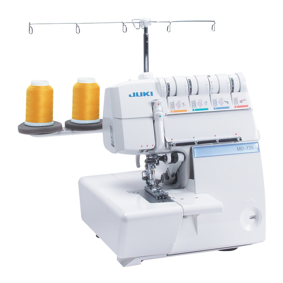
MO-735
Руководство по эксплуатации
Внимание!
Перед использованием швейной
машины внимательно прочтите
правила техники безопасности
и соблюдайте их.
Сохраните данное Руководство
для дальнейшего использования.
2-игольная, 2/3/4/5-ниточная швейная машина (оверлок),
выполняющая плоский шов

-
Contents
-
Table of Contents
-
Troubleshooting
-
Bookmarks
Quick Links
2-Needle,2/3/4/5-Thread Overlock + Cover Stitch Sewing Machine
MO-735N
INSTRUCTION MANUAL
IMPORTANT:
Read all safety regulations carefully and under-stand
them before using your sewing machine. Retain this in-
struction manual for future reference.
EN
Related Manuals for JUKI MO-735N
Summary of Contents for JUKI MO-735N
-
Page 1
2-Needle,2/3/4/5-Thread Overlock + Cover Stitch Sewing Machine MO-735N INSTRUCTION MANUAL IMPORTANT: Read all safety regulations carefully and under-stand them before using your sewing machine. Retain this in- struction manual for future reference. -
Page 2: Safety Instructions
“IMPORTANT SAFETY INSTRUCTIONS” When using an electrical appliance, basic safety precautions should always be followed, including the following: Read all instructions before using this sewing machine. “DANGER To reduce the risk of electric shock:” ____ 1. The appliance should never be left unattended when plugged in. 2.
-
Page 3
Congratulations on your purchase of a JUKI sewing machine. Please be sure to read safety precautions in “To use the sewing machine safely” in the Instruction Manual before use to fully understand the functions and operating procedures of the sewing machine so as to use the sewing machine for a long time. -
Page 4
WARNING For the combination of the material and the thread and needle, in particular, refer to the explanation table in “Replacement of the needle”. If the needle or thread does not match the material used such as in the case that an extra heavy- weight material (e.g., denim) is sewn with a thin needle (#11 or higher), the needle can break result- ing in an unexpected personal injury. -
Page 5: Table Of Contents
Contents Safety instructions ········································ 1-3 Trial sewing, thread tension ····························· 29 Contents························································4 Thread tension ········································ 29-30 Details of the machine ··································· 5-6 Cover/chain stitch functions ····························· 31 • Accessories ·················································6 Cover/chain stitch functions and Preparing the machine / Using the machine ······· 7-8 general operating instructions ·····················…
-
Page 6: Details Of The Machine
Details of the machine Details of the machine Thread guide support Open thread guide Lower looper thread tension dial Upper looper thread tension dial Retractable support rod Right needle thread tension dial Left needle thread tension dial Presser foot pressure regulating knob Foam pad Spool holder pin Thread take-up cover…
-
Page 7: Accessories
Details of the machine View with cloth plate open Chain-looper thread tension dial Threading diagram for chain-looper thread Chain-looper auto-threader Accessories Upper looper converter Needle set 130/705H (SCHMETZ) Needle threader Tweezers Small screwdriver Brush/needle inserter Oiler Large screwdriver Lower knife Electronic foot control Dust cover Nets…
-
Page 8: Preparing The Machine / Using The Machine
Preparing the machine / Using the machine Attaching the foot control Plug foot control into the machine socket (A) and then into main socket (B). The foot control regulates the sewing speed. The sewing speed can be adjusted by increasing or decreasing the pressure on the foot control.
-
Page 9: Thread Stand
Preparing the machine / Using the machine Thread stand Push the support rod firmly into the socket on the back of the ma- chine. Raise the support rod (C) fully, turning slightly until the position catches engage. Position the thread guide (D) on the thread stand so that the arrow is to the front.
-
Page 10: Thread / Cones / Spools
Preparing the machine / Using the machine Thread / cones / spools Large spools The anti-vibration cone should be If large industrial spools are used, used with the wider edge at the position the anti-vibration cone bottom on the spool holder pin upside down on the spool holder when sewing with cones.
-
Page 11: Two Step Presser Foot Lifter With Integrated Front
Using the machine Two step presser foot lifter with integrated front foot lift To raise the presser foot, lift the presser foot lever on the rear of the machine, until it engages (A). It can be raised again to the maximum height and held in this position to provide more space between presser foot and stitch plate (B).
-
Page 12: Looper Cover
Using the machine Looper cover To open, press to the right with your thumb in the indent provided and tilt the cover towards you. To close push it up and press lightly to the right. The cover engages automatically. Safety switch: The machine does not run when the looper cover is opened.
-
Page 13: Inserting The Needles
Using the machine Inserting the needles Needles can be inserted quickly and easily with the practical needle inserter (A). Switch the machine off (power switch ”O”) Disconnect machine from electricity supply. Turn handwheel towards you until needles are fully raised. Match the matching up marks on handwheel and side cover.
-
Page 14: Needle And Thread
Needle and thread Needles Needles must be in perfect condition. Problems can occur if needles: A are bent. B are damaged or blunt. C have hooked points. Needle and thread The needle size used depends on the thread. The needles should be in accordance with thread used. When sewing, the thread is fed through the long groove in the needle.
-
Page 15: Adjustments And Settings
Adjustments and settings Stitch length It can be adjusted while sewing. The stitch length is infinitely variable from 1-4mm. Most overlock work is done with a basic setting of 2.5mm. Cutting width Switch the machine off (power switch ”O”) Disconnect machine from electricity supply. •…
-
Page 16: Differential Feed
Adjustments and settings Differential feed There are two feed dogs one front (C) and one rear (D). The two feed dogs move independently and the distance each feed dog travels during one complete movement can be adjusted. The differential feed prevents fluting or waving in knitted or stretch fabrics and movements between the layers of fabric.
-
Page 17: Gathering
Adjustments and settings Gathering Using the differential feed, a single layer of fabric can be gathered before sewing it to the garment. For example, sleeve heads and lower edges,yokes, lace edging or frills. Adjustment: • Stitch: 4-thread overlock • Differential feed: 2 •…
-
Page 18: Roll Hemming
Adjustments and settings Roll hemming • Turn the handwheel towards you until the needles are fully raised. • For roll hemming, pull the selection lever to the front marking on the stitch plate, furthest from the presser foot (C). • For overlocking, push the selection lever to the rear marking on the stitch plate, nearest to the presser foot (D).
-
Page 19: Sewing In Tape
Settings, practical sewing Sewing in tape The standard presser foot is equipped with a tape guide. A tape can be sewn into the shoulder or side seams of garments made from knits or stretch fabrics to prevent stretching. • Turn handwheel towards you until needles are fully raised. Match the matching up marks on handwheel and side cover.
-
Page 20: Threading Preparations / Tips
Threading preparations / tips Switch the machine off (power switch ”O”) • Support rod with thread guide must be fully raised. • Open the looper cover. • Turn the handwheel towards you until the needles are fully raised. Match the matching up marks on handwheel and side cover. •…
-
Page 21: Stitch Chart
Stitch chart Stitch Stitch width Thread tension Basic settings 4-Thread overlock with integrat- Left needle (yellow) 3-5 ed safety seam Stitch length: 2.5 Right needle (green) 3-5 Cutting width: 3 7-9 mm, right and left needle Differential: N-2 (knits) Upper looper (blue) 3-5 0.7-N (wovens) Lower looper (red) 3-5 3-Thread super stretch…
-
Page 22
Stitch chart Stitch Stitch width Thread tension Basic settings 2-Thread chain stitch Right needle (brown) 3-5 Stitch length: 2.5 7-9 mm, right needle Chain looper M Differential: N-2 (knits) 3-Thread overlock (left needle) + Left needle (brown) 3-5 chain stitch Right needle (green) 3-5 Stitch length: 2.5 7-9 mm, right and left needle… -
Page 23: Threading 4/3 Thread Ol
Threading 4/3 Thread OL 1. Upper looper thread, blue markings Place the spool on the spool holder pin as illustrated. (1) Bring the thread up from the spool and lay it from the back to the front into the guide. (2) Thread the first machine guide.
-
Page 24: Lower Looper
Threading 4/3 Thread OL 2. Lower looper thread, red markings Place the spool on the spool holder pin as illustrated. (1) Bring the thread up from spool and lay it from the back to the front into the guide. (2) Thread the first machine guide. (3) Slip the thread through the groove.
-
Page 25: Right-Hand Needle
Threading 4/3 Thread OL 3. Right-hand needle, green markings Place the spool on the spool holder pin as illustrated. (1) Bring the thread up from the spool and lay it from the back to the front into the guide. (2) Thread the first machine guide. (3) Slip the thread through the groove.
-
Page 26: Left-Hand Needle
Threading 4/3 Thread OL 4. Left-hand needle, yellow markings Place the spool on the spool holder pin as illustrated. (1) Bring the thread up from the spool and lay it from the back to the front into the guide. (2) Thread the first machine guide. (3) Slip the thread through the groove.
-
Page 27: Threading, Chain Stitch And Ol
Threading, Chain stitch and OL 1. Threading chain stitch looper (purple) Place the spool on the spool holder pin as illustrated. (1,2) Bring the thread up from the spool and lay it from the front to the back into the guide. (3,4) Thread the guides.
-
Page 28
Threading, Chain stitch and OL 2. Chain-needle, brown markings (use yellow tension) Place the spool on the spool holder pin as illustrated. (1) Bring the thread up from the spool and lay it from the back to the front into the guide. (2) Thread the first machine guide. -
Page 29
Threading, Chain stitch and OL Threading, Chain stitch 1. Threading chain looper (purple): see page 26 2. Chain-needle, brown markings (use yellow tension): see page 27 3-thread overlock (left needle)+Chain stitch 1. Upper looper thread, blue markings: see page 22 2. -
Page 30: Trial Sewing, Thread Tension
Trial sewing, thread tension Sewing test After threading make a trial run. Always use a double layer of fabric to check the stitch formation and thread tension properly. • Switch the machine on (“ I “).). • Set all tensions to 4. •…
-
Page 31: Thread Tension
Thread tension Thread tension Thread tension should be properly adjusted to suit the various types of work. The ideal tension setting for most fabrics and threads is between 3 and 5. How- ever this can vary quite considerably when special threads such as filament, woolly nylon, buttonhole twist (cordonnet), pearl yarn or decorative threads are used.
-
Page 32: Cover/Chain Stitch Functions
Cover/chain stitch functions Cover stitch The 5 mm wide cover stitch is formed with two or three needle threads and one looper thread. The needle threads appear as two or three parallel lines on the right side. The 2.5 mm cover stitch is sewn with one looper thread and two needle threads.
-
Page 33: Cover/Chain Stitch Functions And General Operating Instructions
Cover/chain stitch functions and general operating instructions Switch the machine off (power switch ”O”) Upper looper releaseIf If the cover stitch and chain stitch without overlock are sewn, the upper looper must first be lowered. — Turn the handwheel to bring the needles and upper looper into the lowest po- sition.
-
Page 34
Cover/chain stitch functions and general operating instructions Knife guard / cover and chain stitch extension plate When the machine is converted to cover/chain stitch, the knife guard in the looper cover is replaced by cover stitch extension plate. The extension plate covers the released upper looper and extends the stitch plate to the right of the presser foot. -
Page 35: Threading 4 Thread Cover Stitch
Threading 4 thread cover stitch 1. Threading cover stitch looper (purple) Place the spool on the spool holder pin as illustrated. (1,2) Bring the thread up from the spool and lay it from the back to the front into the guide. (3,4) Thread the guides.
-
Page 36: Cover Stitch R Needle
Threading 4 thread cover stitch 2. Cover stitch R needle (pink) markings Place the spool on the spool holder pin as illustrated. (1) Bring the thread up from the spool and lay it from the back to the front into the guide. (2) Thread the first machine guide.
-
Page 37: Cover Stitch C Needle
Threading 4 thread cover stitch 3. Cover stitch C needle (pink) markings Place the spool on the spool holder pin as illustrated. (1) Bring the thread up from the spool and lay it from the back to the front into the guide. (2) Thread the first machine guide.
-
Page 38: Cover Stitch L Needle
Threading 4 thread cover stitch 4. Cover stitch L needle (pink) markings Place the spool on the spool holder pin as illustrated. (1) Bring the thread up from the spool and lay it from the back to the front into the guide. (2) Thread the first machine guide.
-
Page 39: Threading 3 Thread Cover Stitch (Wide)
Threading 3 thread cover stitch (wide) Preparation 3 thread cover stitch (wide) Cover stitch needle R (pink) Cover stitch needle L (pink)
-
Page 40: Threading 3 Thread Cover Stitch (Narrow)
Threading 3 thread cover stitch (narrow) Preparation 3 thread cover stitch (narrow) Cover stitch needle C (pink) Cover stitch needle L or R (pink) L or C C or R Needle L, C Needle C, R…
-
Page 41: Threading Chain Stitch
Threading chain stitch Preparation chain stitch Chain stitch needle R (brown)
-
Page 42: Sewing Test And Tension Adjustment
Sewing test and tension adjustment Sewing Test After threading make a sewing test on a double layer of fabric to check the stitch formation and the thread tension. Cover stitch sewing test — Plug the machine in and switch it on (power switch to “I”) — Set the tensions to 3-5.
-
Page 43: Tension Adjustments
Tension adjustments Tension adjustments Cover stitch The right needle thread forms loops on the underside: Tighten the right needle (upper looper) tension (pink, R) The center needle thread forms loops on the underside: Tighten the right needle tension (pink, C). The left needle thread forms loops on the underside: Tighten the left needle tension (pink, L).
-
Page 44: Practical Sewing-Cover Stitch
Practical Sewing-Cover stitch Securing the seam end, cover stitch After removing your work turn it over to the wrong side. Secure the seam by pulling the loop (1) towards the left. If the looper thread is subsequently pulled to the upper side, the needle thread loops (2) are visible in the stitch formation and can also be pulled through to the wrong side and knotted.
-
Page 45: Simple Hem
Practical Sewing-Cover stitch Simple hem Stitch length: 3-4Differential: N-2 (depending on fabric) — Mark hem depth and fold or press. — Place fabric under the foot and guide the folded edge along a line on the stitch plate. The hem is sewn and the raw edge on the wrong side is neatened simul- taneously.
-
Page 46: Edges With Elastic
Practical Sewing-Cover stitch Edges with elastic Stitch length: 3-4 Differential: 0.7-N — Sew on elastic with 4-thread overlock. — Turn the raw edge to the width of the elastic and top stitch from the right side. Guide the fold along the right section of the foot or use one of the lines on the stitch plate as a guide.
-
Page 47: Top Stitching Seams /Ribbing/Yokes
Practical Sewing-Cover stitch Top stitching seams /ribbing/yokes Stitch length :3-4 Differential: 0.7-N — Fold or press seam to one side. — Edge stitch (or at distance desired) from the right. — Guide the edge of the fabric along the side sections of the foot. Cover stitch is perfect for top and edge stitching overlock seams in all stretch fabrics to give a professional, durable and decorative finish.
-
Page 48: Maintenance
Maintenance WARNING : Please refer to the safety instructions. Changing the upper knife The upper knife (moving knife) is made from special hardened ma- terial. Replace the upper knife only when the knife blade tip is damaged. For a replacement, contact your local dealer. Changing the lower knife Main switch on “O”.
-
Page 49: Trouble Shooting Guide
Trouble shooting guide Problem Cause Solution Page The machine does • Looper or cloth plate cover is open. • Close the looper or the cloth plate cover. not sew: • The main switch is not on. • Switch machine on. (Main switch to “I”) •…
-
Page 50: Technical Data
Technical data Stitch choice Cover stitch 3 needles, 1 looper: 5 mm 2 needles, 1 looper: 5 mm 2 needles, 1 looper: 2.5 mm Chain stitch 1 needle, 1 looper: 2 thread chain stitch 1 needles, 1 loopers: chain stitch + 2 thread overlock Over lock 2 needles, 2 loopers: 4 thread overlock with integrated safety seam 1 needle, 2 loopers: 3 thread overlock, flatlock roll hem…
-
Page 51: Optional Accessories
Optional Accessories • Blind stitch presser foot • Gathering presser foot A9810 634 0A0A A9860 655 0A0C • Elasticator • Piping presser foot A9815 655 0A0A A9865 655 0A0A Cording presser foot • Beading presser foot A9820 655 0A0A A9870 634 0A0A •…
-
Page 52
2-11-1, TSURUMAKI, TAMA-SHI, TOKYO, 206-8551, JAPAN PHONE : (81)42-357-2341 FAX : (81)42-357-2379 Copyright © 2020 JUKI CORPORATION All rights reserved throughout the world. 40239276 002003…
 12:23
12:23
Коверлок Juki MO- 735
 13:27
13:27
ОНЛАЙН ТРЕЙД. РУ. Коверлок Juki MO-735, Код товара: 160097
 05:27
05:27
Как заправить коверлок: распошивка
 02:20
02:20
Коверлок Juki MO-735
 07:56
07:56
JUKI MO-735 — Chapter 3: Threading
 14:16
14:16
Реинкарнатор. Выбор оверлока Juki. Советы
MO-735
Руководство по эксплуатации
Внимание!
Перед использованием швейной
машины внимательно прочтите
правила техники безопасности
и соблюдайте их.
Сохраните данное Руководство
для дальнейшего использования.
2-игольная, 2/3/4/5-ниточная швейная машина (оверлок),
выполняющая плоский шов

ВАЖНЫЕ ИНСТРУКЦИИ ПО ТЕХНИКЕ БЕЗОПАСНОСТИ
При эксплуатации электрической машины необходимо всегда соблюдать основные правила техники
безопасности, включая следующие:
Внимательно прочитайте все инструкции, прежде чем приступать к эксплуатации машины!
«ОПАСНОСТЬ” – для защиты от поражения током:
1. Никогда не оставляйте включ¸нную в сеть машину без присмотра.
2. После пользования машиной или перед е¸ чисткой всегда вынимайте вилку из розетки электросети.
3. Перед заменой лампочки освещения всегда отключайте машину от сети. Для модели MO-735 исполь-
зуйте только лампочками 12V, 15 W
«ВНИМАНИЕ» – для защиты от ожогов, пожара, поражения
током, и травм:
1. Нельзя пользоваться этой машиной в качестве игрушки. Особую осторожность следует проявлять,
когда машиной пользуются дети или когда они находятся рядом с работающей машиной.
2. Машина должна использоваться только по назначению в соответствии с инструкциями, изложенными
в данном Руководстве. Следует применять только принадлежности завода –изготовителя, перечислен-
ные в этом Руководстве.
3. Машиной нельзя пользоваться, если неисправен е¸ электрошнур или вилка, если она неправильно
функционирует, в случае е¸ падения или соприкосновения с водой. Отправьте е¸ ближайшему дилеру
или в ближайший центр обслуживания на проверку и ремонт,
а также для регулировки электрики и механики.
4. Никогда не работайте на машине с закрытыми вентиляционными отверстиями.
Регулярно очищайте вентиляционные отверстия машины и ножную педаль от пуха, пыли и остатков
ткани.
5. Держите пальцы рук вдали от всех движущихся деталей. Особенно осторожным нужно
быть в рабочей зоне иглы и ножей.
6. Пользуйтесь всегда соответствующей игольной пластиной. Применение неправильной пластины
может привести к поломке иглы.
7. Не работайте гнутыми иглами.
8. Во время шитья не тяните и не растягивайте материал. Игла может погнуться и сломаться.
9. Поставьте сетевой выключатель машины на «0», если хотите внести изменения в зоне иглы, перед та-
кими операциями, как заправка нити в иглу, замена иглы, заправка петлителя или замена лапки и т.п.
10. Прежде чем снять какую-либо крышку, открыть крышку, чтобы поднять нож или заправить петлитель,
смазать машину или произвести другие, выполняемые пользователем изменения, описанные в данном
Руководстве, сначала извлеките вилку из розетки электросети.
11. Не вводите никаких предметов в отверстия машины.
12. Не эксплуатируйте машину вне помещения.
13. Не эксплуатируйте машину в местах, где пользуются аэрозолями или применяют кислород.
14. Для отсоединения машины от сети, поставьте главный выключатель на «0» и выньте вилку из розет-
ки.
15. Не вытаскивайте вилку из розетки, держась за шнур. Беритесь за вилку и вынимайте е¸ из розетки.
16. Если машина не эксплуатируется, она всегда должна быть отключена от сети, т.е. вилка вынута из
розетки.
17. При повреждении сетевого шнура машины обратитесь к авторизованному дилеру или в ближайшую
мастерскую. Замена шнура допускается только на аналогичный.
18. Машина оборудована двойной защитой от поражения электрическим током (изоляцией) (кроме США
и Канады).
19. При попадании масла в глаза, немедленно промойте их водой. При случайном попадании масла в
желудок обратитесь к врачу.
«ТЕХНИЧЕСКОЕ ОБСЛУЖИВАНИЕ МАШИН С ДВОЙНОЙ ИЗО-
ЛЯЦИЕЙ» (кроме США и Канады)
Машина с двойной изоляцией снабжена вместо заземления двумя изоляционными системами.
Средства заземления в машинах с двойной изоляцией нет и его не следует применять. Техническое
обслуживание таких машин требует максимального внимания и хорошего знания системы, поэтому за-
ниматься им должен высококвалифицированный персонал. Для технического обслуживания и ремонта
пользуйтесь только деталями завода — изготовителя.
Машина с двойной изоляцией маркируется словом: «Двойная изоляция» или символом ( ).
ХРАНИТЕ ЭТИ ИНСТРУКЦИИ
Эта машина предназначена только для использования в быту.
-1-

-2-
Важные инструкции по технике безо-
пасности…………………………………………..
Содержание……………………………………..
Детали машины………………………………..
Принадлежности………………………………
Пуск машины в эксплуатацию……………..
Подключение ножной педали…………….
Монтаж шпулярника………………………….
Установка шпуледержателя катушки
плоского шва…………………………………….
Нитки, катушки, шпули………………………
Эксплуатация и работа
Выключатель электропитания и осве-
щения ……………………………………………..
Подъ¸м верхнего ножа……………………..
Двухпозиционный подъемник лапки
со встроенным устройством подъема
передней части лапки……………………….
Замена лапки…………………………………..
Как открыть и закрыть крышку петли-
теля…………………………………………………
Как открыть и закрыть крышку стола
для материала…………………………………..
Маховик …………………………………………
Как вставить иглу/Иглы и нитки…………
Регулировки и установки
Длина стежка…………………………………..
Ширина обреза………………………………..
Дифференциальная подача ткани………
Сборение………………………………………..
Конвертер верхнего петлителя…………..
Подрубка руликом…………………………….
Регулировка давления прижимной лап-
ки……………………………………………………
Втачивание ленты……………………………
Регулировки / Практическое шитье
Обрыв ниток……………………………………
Роспуск швов…………………………………..
Подготовка / Указания ……………………..
Таблица швов………………………………….
Заправка ниток
Верхний петлитель ………………………….
Нижний петлитель …………………………..
Правая игла…………………………………….
Левая игла………………………………………
Заправка петлителя цепного стежка…..
Заправка иглы цепного стежка…………..
Заправка цепного стежка и оверлока…
Пробное шитье, натяжение стежка……..
Функции плоского/цепного стежка…….
Общие правила ………………………………
Защита ножа / платформа для плоско-
го и цепного швов…………………………….
Заправка плоского шва
Заправка петлителя плоского шва………
Заправка правой иглы для плоского
шва………………………………………………….
Заправка центральной иглы ……………..
Заправка для 3-ниточного плоского шва
(широкого)………………………………………..
Заправка для 3-ниточного плоского шва
(узкого)…………………………………………….
Заправка для цепного стежка………………
Цепной стежок – пробное шитье ………..
Плоский шов – пробное шитье …………..
Регулировка натяжения………………………
Практическое шитье – плоский шов
Закрепка конца шва………………………….
Роспуск шва…………………………………….
Простая подрубка…………………………….
Плоский соединительный шов……………
Шов с эластичным краем………………….
Стачивание …………………………………….
Покровные швы / рубчик / обметка
бисера …………………………………………….
Цепной стежок – практическое
шитье
Сборение………………………………………..
Стачивание …………………………………….
Техническое обслуживание
Замена верхнего ножа………………………
Замена нижнего ножа……………………….
Замена лампочки освещения ……………
Чистка и смазка ……………………………..
Неисправности и их устранение ………
Спецификации…………………………………..
Дополнительные принадлежности………..
1
2
3
4
5
5
5
5
6
7
7
7
7
8
8
8
9, 10
11
11
11
13
13
13
14
14
14
14
15
16
18
19
20
21
21
21
22
24
26
26
27
28
29
29
30
31
32
34
34
35
36
36
36
37
38
38
38
39
39
40
40
40
40
41
42
43
Содержание

-3-
Детали машины
1. Крышка петлителя с защитой ножа
2. Как открыть крышку петлителей
3. Крышка стола для материала
4. Подсветка
5. Крышка нитепритягивателя
6. Регулятор давления прижимной лапки
7. Регулятор натяжения левой игольной
нити
8. Регулятор натяжения правой игольной
нити
9. Регулятор натяжения верхней нити
петлителя
10. Регулятор натяжения нижней нити
петлителя
11. Телескопическая стойка шпулярника
12. Стойка нитенаправителей.
13. Нитенаправитель
14. Стержень катушки
15. Полиуретановая прокладка
16. Глушитель вибрации
17. Стойка катушек
18. Регулятор длины стежка
19. Регулятор дифференциальной подачи
материала.
20. Маховик
21. Боковая крышка
22. Контрольные метки
23. Разъ¸м шнура питания
24. Выключатель электропитания и осве-
щения
25. Защита ножа
Детали машины
1. Нож для обрезки нитей
2. Рычаг подъема лапки
3. Игольная пластина
4. Прижимная лапка
5. Верхний нож
6. Зажим иглы
Вид с открытой крышкой петлителей
1. Рычаг выбора режима оверлока или под-
рубки руликом
2. Нижний нож
3. Регулятор ширины обрезки
4. Автозаправщик нижнего петлителя
5. Установочный винт нижнего ножа
6. Нижний петлитель
7. Верхний петлитель
8. Схема заправки
9. Паз заправки петлителя
Детали машины

-4-
Вид с открытой крышкой стола
1. Автозаправщик цепного стежка
2. Натяжитель нити петлителя цепного
стежка
3. Схема заправки нити цепного стежка
Принадлежности
1. Набор игл SCHMETS 130/70H
2. Малая отвертка
3. Пинцет
4. Конвертер верхнего петлителя
5. Нитевдеватель
6. Щетка – заправщик иглы
7. Электронная педаль
8. Масленка
9. Сетки
10. Нижний нож
11. Колпачки на катушки
12. Сумка для принадлежностей
13. Чехол от пыли
14. Большая отвертка
15. Приставной столик плоского / цепного
стежка
16. Лапка для выполнения плоского шва
17. Контейнер для сбора мусора
18. Шпуледержатель
Детали машины

-5-
Подсоединение ножной педали
Подключить ножную педаль управления
к машине, вставив е¸ вилку в разъ¸м А
машины.
Подключить ножную педаль к розетке
электросети (В).
При сильном нажатии на педаль скорость
машины повышается, при ослаблении дав-
ления (л¸гком нажатии) скорость снижается.
ПРЕДУПРЕЖДЕНИЕ
Вилка электрошнура у этой машины поля-
ризована (один контакт шире другого). Для
сокращения риска поражения током она
предназначена только для поляризованной
розетки электросети. Если вилка не вошла
полностью в розетку, переверните е¸. Если
она вс¸ равно не входит в розетку, обрати-
тесь к квалифицированному электрику для
установки соответствующей поляризован-
ной розетки. Вилку нельзя модифициро-
вать никаким образом (Только для США и
Канады)
* Для модели МО-735 использовать только
ножную педаль YC-482N (для всех стран,
кроме США и Канады).
Контейнер для сбора мусора
Установите контейнер для сбора мусора
в отверстие крышки петлителя. В него во
время шитья будут попадать обрезки ткани,
что позволит вам держать рабочее место в
чистоте.
Подготовка машины / Работа на машине
Монтаж шпулярника
Установить стойку шпулярника в гнездо на
задней крышке машины.
Вытянуть полностью стойку шпулярника (С).
Поворачивайте стойку, пока не раздастся
щелчок при срабатывании фиксатора по-
ложения.
Насадить нитенаправитель (D) на стойку так,
чтобы его маркировка в виде стрелки была
обращена к передней части машины.

-6-
Нитки/ Бобины / Шпули
При шитье конусными бобинами исполь-
зуйте антивибрационные патроны, уста-
новленные на бобинодержатель широкой
стороной вниз.
Для шпуль с большим внутренним диа-
метром установите антивибрационные
патроны в перев¸рнутом виде.
При шитье маленькими домашними катуш-
ками, снимите антивибрационные патроны.
Если нитки соскальзывают с катушек,
используйте сетки, входящие в комплект
принадлежностей машины.
Подготовка машины / Работа на машине
Установка шпулярника для цепного
стежка
Поднимите полиуретановую подкладку (А),
вставьте направляющие (С) шпулярника (B)
в направляющие верхней части подставки
в направлении слева, пока он не займет
позицию (E). Надавите на напарвляющие
(D) до щелчка (F).

-7-
Работа на машине
Выключатель электропитания и осве-
щения
Выключатель электропитания и освещения
расположен на боковой крышке машины
слева от розетки шнура питания.
Нажатием выключателя на «0» машина от-
ключается от сети.
При установке выключателя на «I» машина
включается и готова к работе. Подсветка
горит.
В позиции выключателя «I» машина и под-
светка включены.
Подъем верхнего ножа
Отключите машину от сети (выключатель
на «О»)
Поворачивайте маховик «к себе» до полно-
го подъема игл.
Откройте крышку петлителя
Нажмите на держатель верхнего ножа (Е)
вправо. Поворачивайте регулятор (F) по
часовой стрелке до тех пор, пока нож не
встанет в положение, показанное на рис. G.
Двухпозиционный рычаг подъема лапки
со встроенной функцией подъема
передней части лапки.
Для подъема лапки поднимите рычаг подъ-
ема лапки, расположенный на задней части
машины, в положение (А). Для достижения
максимального расстояния между лапкой и
игольной пластиной рычаг можно устано-
вить в положение (В).
В обоих положениях (А и В) передняя часть
лапки автоматически приподнимается.
Примечание: При поднятой лапке осла-
бляются все натяжные пружины, что облег-
чает заправку машины нитками.
Смена прижимной лапки
Поднимите лапку
Поворачивайте маховик «к себе» до пол-
ного подъема игл. Совместите контрольные
метки на маховике и боковой крышке.
Нажмите на зажим (С), чтобы освободить
лапку. Поднимите держатель лапки в
верхнее положение (В) и сдвинув лапку
влево, извлеките ее. Для установки лапки
положите ее под держатель. Установочный
вырез на держателе должен быть совмещен
с крепежной осью лапки (D). Опустите
держатель на лапку и она автоматически
защелкнется в держателе.
(Е) – Стандартная лапка
(F) – Лапка для выполнения плоского шва
Регулировка давления прижимной лапки
плоского шва.
При выполнении плоского шва (купальные,
гимнастические костюмы и .т.д.) поставьте
регулятор давления в положение L.
При обычных работах рычаг регуляторы
давления должен находиться в переднем
положении.
ПРЕДУПРЕЖДЕНИЕ
Отключите машину от сети ! (Выключа-
тель в положении «О»).

-8-
Крышка петлителей
Чтобы открыть крышку петлителей, боль-
шим пальцем надавите вправо на выемку
в крышке и потяните ее на себя. Закрывая
крышку, слегка прижмите ее вправо. Крыш-
ка закроется автоматически.
Выключатель питания! Машина не будет
работать с открытой крышкой петлителей.
Стол для ткани
Откройте стол для ткани, толкнув его влево.
Закройте стол для ткани, толкнув его
вправо.
*Выключатель питания! Машина не будет
работать с открытым столом для ткани.
Маховик
Маховик вращается против часовой стрелки,
так же, как в бытовых швейных машинах.
Работа на машине

-9-
Как установить или сменить иглы
Иглы легко устанавливаются с помощью заправщика игл (А)
Выключите машину (выключатель на «О»)
Отключите машину от сети
Поверните маховик на себя до полного подъема игл. Совместите контрольные метки на
маховике и боковой крышке.
Опустите прижимную лапку.
Малой отверткой ослабьте фиксирующие винты игл и извлеките иглы (В).
Вставьте иглу в отверстие заправщика игл фаской к задней стороне машины, затем с
помощью заправщика установите иглу в отверстие иглодержателя как можно глубже. За-
верните фиксатор, затем повторите операцию с левой иглой, затем еще раз протяните
винты (С).
Работа на машине

Комментарии
- Manuals
- Brands
- JUKI Manuals
- Sewing Machine
- MO-735
- Service manual
-
Contents
-
Table of Contents
-
Bookmarks
Quick Links
®
MO-735/734DE
Service Manual
Einstellanleitung
Manual d’instruction pour les réglages
Related Manuals for JUKI MO-735
Summary of Contents for JUKI MO-735
-
Page 1
® MO-735/734DE Service Manual Einstellanleitung Manual d’instruction pour les réglages… -
Page 3
Safety Regulation Sicherheitsvorschriften Règles de sécurité Attention Attention Attention Attention Attention Repair and service work may only be done once the machine has been disconnected from the Repair and service work may only be done once the machine has been disconnected from the Repair and service work may only be done once the machine has been disconnected from the Repair and service work may only be done once the machine has been disconnected from the Repair and service work may only be done once the machine has been disconnected from the… -
Page 4: Table Of Contents
35. Einstellung der Vorspannungs Auslöseplatte 17. Montage des Kettengreifer Nadelschutz (MO-735) ····· 27 ( M O — 7 3 4 D E ) · · · · · · · · · · · · · · · · · · · · · · · · · · · · · · · · · · · · · · · · · · · · · · · · · · · · · · · · · · · · · · · · · · 5 1 18.
-
Page 5
33. Réglage latéral du crochet d’enfilage (Seulement 15. Rayon du boucleur de double-chaînette (MO-735) ······ 24 l ’ a i g u i l l e g a u c h e ) ( M O — 7 3 4 D E ) · · · · · · · · · · · · · · · · · · · · · · · · · · · · · · · · · · · · · · · 4 8 16. -
Page 6: Specifications
2 — a i g u i l l e s 4 — f i l s s u r j e t à 4 f i l l s , 2 — a i g u i l l e s 3 — f i l s , 3 — a i g u i l l e s 4 — f i l s p o i n t e n v e l o p p a n t , 1 — a i g u i l l e 2 — f i l s p o i n t c h aî n e t t e (MO-735)
-
Page 7: Dépose Des Couvercles
2. Removing order of covers: 2. Removing order of covers: 2. Removing order of covers: 2. Removing order of covers: 2. Removing order of covers: 2. Reihenfolge beim Entfernen der Abdeckungen: 2. Reihenfolge beim Entfernen der Abdeckungen: 2. Reihenfolge beim Entfernen der Abdeckungen: 2.
-
Page 8
— Loosen and remove the screws (1), remove the slit threading cover. ( a ) — Loosen the screw (2), drop the looper take ups (3) into the lowest position. — Loosen the screw (4), lift the bracket above the front cover (B). (MO-735 o n l y ) ( 1 ) — Loosen and remove the screws (5). -
Page 9
— Loosen and remove the screws (4). — Remove the base plate. (D) ( 1 ) * Remark: Do not lay the machine on the back side. The thread guide ± may get damaged. (MO-735 only) 2.3. Die Bodenplatte: 2.3. Die Bodenplatte: 2.3. Die Bodenplatte: 2.3. -
Page 10
2.4. The rear cover and the handle: 2.4. The rear cover and the handle: 2.4. The rear cover and the handle: 2.4. The rear cover and the handle: 2.4. The rear cover and the handle: — Loosen and remove the screws (5). — R a i s e t h e p r e s s e r b a r l i f t i n g l e v e r ( 6 ) . -
Page 11: Installation Of The Throat Plate
• Vis de réglage. Ž G r i ffe d’entraînement. • C e n t r e d e p i q û r e d e l ’ a i g u i l l e . MO-735 MO-735 MO-735…
-
Page 12: H A U T E U R D E L A B A R R E À A I G U I L L
4. Height of the needle bar 4. Höhe der Nadelstange 4. Hauteur de la barre à aiguille 4.1. Checking items: 4.1. Checking items: 4.1. Checking items: 4.1. Checking items: 4.1. Checking items: Œ Right hand needle. • T h r o a t p l a t e . — Check that the distance between the throat plate surface and the OL Œ…
-
Page 13: Position Of The Feed Dog
. ( A ) . — Check that the distance between the throat plate and the most receded position of the feed dog at stitch length 4 is (MO-735) 1 mm (B) and (MO- 734DE) 3 mm.(B) — Check at the most-advanced position in max.
-
Page 14
— Loosen the setscrews (D) of the main feed dog (1). — At the most receded position of the feed dog perform adjustment so that the clearance is (MO-735) 1 mm (B) and (MO- 734DE) 3 mm (B) with respect to the slot in the throat plate. -
Page 15: Réglage De La Course De La Griffe D’entraînement
6. Adjusting the stroke of the sub feed dog 6. Einstellen des Transportweges des Nebentransporteurs 6. Réglage de la course de la griffe d’entraînement secondaire 6.1. Checking items: 6.1. Checking items: 6.1. Checking items: 6.1. Checking items: 6.1. Checking items: Œ…
-
Page 16: Höhe Des Tr A N S P O R T E U R
7. Height of the feed dog 7. Height of the feed dog 7. Height of the feed dog 7. Height of the feed dog 7. Height of the feed dog 7. Höhe des T 7. Höhe des T ransporteurs ransporteurs 7.
-
Page 17: Réglage Du Mouvement De La Griff E D ‘ E N T R A Î N E M E N
2.5. (MO-734DE) * Remark: By the MO-735 check with the right hand cover stitch needle. 8.1. Kontrollieren: 8.1. Kontrollieren: 8.1.
-
Page 18: Position Der Schwungstücke Und Der Exzenter
9 . P r e m i è r e v i s s u r l e p l a t . 10. La barre à aiguille au point la plus haut, les marques du volant et du couvercle latéral sont dans la même position. Remarque: 8/9. Seulement pour MO-735 — 1 6 -…
-
Page 19
• Lower looper blade point. — Check that the distance from the center of the lower looper shaft (2) to the lower blade point (4) is 66.0 ± 0.15 mm (A) (MO-735) and 66.3 ± 0.15 mm (A) (MO-734DE). 10.1. Kontrollieren: 10.1. -
Page 20: E I N S T E L L E N D E S U N T E R G R E I F E R — E I N F Ä D L E R
1 1 1 1 1 1. Adjusting the looper threader 1. Adjusting the looper threader 1. Adjusting the looper threader 1. Adjusting the looper threader 1. Adjusting the looper threader 1 1 1 1 1 1. Einstellen des Untergreifer-Einfädlers 1. Einstellen des Untergreifer-Einfädlers 1.
-
Page 21
1 1 1 1 1 1.2. How to perform adjustment: 1.2. How to perform adjustment: 1.2. How to perform adjustment: 1.2. How to perform adjustment: 1.2. How to perform adjustment: — Loosen the setscrew (A). — Adjust the lower looper thread guide arm by moving up or down. — Retighten the setscrew (A). -
Page 22
12. Adjustment of the loop lift 12. Adjustment of the loop lift 12. Adjustment of the loop lift 12. Adjustment of the loop lift 12. Adjustment of the loop lift 12. Einstellen des Schlingenhubes 12. Einstellen des Schlingenhubes 12. Einstellen des Schlingenhubes 12. -
Page 23
13. T 13. T 13. T 13. T 13. Timing between upper and lower looper iming between upper and lower looper iming between upper and lower looper iming between upper and lower looper iming between upper and lower looper 13. Gegenseitiges Abstimmen des oberen und unteren Greifers 13. -
Page 24: Montage Der Nadelschutz-Vo R R I C H T U N
— V é r i f i e r q u e l ’ é c a r t e m e n t e n t r e l e s a i g u i l l e s à l a p o s i t i o n l a p l u s b a s s e e t la protection antérieure de l’aiguille soit de 0.05 — 0.1 mm (A). (MO-735) — Vérifier que l’écartement entre les aiguilles et la protection mobile…
-
Page 25
— Move the rear needle guard (2) to make adjustment (B). — Retighten the setscrews (C). — Loosen the setscrews (D) of the front needle guard (3). — Move the front needle guard (3) to make adjustment (A). — Retighten the setscrews (D). (MO-735) 14.2. Einstellvorgang: 14.2. Einstellvorgang: 14.2. Einstellvorgang: 14.2. -
Page 26: Rayon Du Boucleur De Double-Chaînette (Mo-735)
15. Radius of the double-chain looper (MO-735) 15. Radius of the double-chain looper (MO-735) 15. Radius of the double-chain looper (MO-735) 15. Radius of the double-chain looper (MO-735) 15. Radius of the double-chain looper (MO-735) 15. Radius des Doppelkettengreifers (MO-735) 15.
-
Page 27: Einstellen Des Schlingenhubes Und Spiel Des Doppelketten-Greifers Zu Den Nadeln (Mo-735)
16. Réglage de la remontée de la boucle; de l’écartement entre la pointe 16. Réglage de la remontée de la boucle; de l’écartement entre la pointe du boucleur double-chaînette et les aiguilles. (MO-735) du boucleur double-chaînette et les aiguilles. (MO-735) du boucleur double-chaînette et les aiguilles.
-
Page 28
16.3. Adjusting the clearance between the needles and the 16.3. Adjusting the clearance between the needles and the 16.3. Adjusting the clearance between the needles and the 16.3. Adjusting the clearance between the needles and the 16.3. Adjusting the clearance between the needles and the Œ… -
Page 29: Montage Des Kettengreifer Nadelschutz (Mo-735)
17. Installation of the double-chain needle guards (MO-735) 17. Installation of the double-chain needle guards (MO-735) 17. Installation of the double-chain needle guards (MO-735) 17. Installation of the double-chain needle guards (MO-735) 17. Installation of the double-chain needle guards (MO-735) 17.
-
Page 30: Position Des Doppelketten-Fadenzieher (Mo-735)
18. Position des Doppelketten-Fadenzieher (MO-735) 18. Position des Doppelketten-Fadenzieher (MO-735) 18. Position du boucleur de fil du boucleur double-chaînette (MO-735) 18. Position du boucleur de fil du boucleur double-chaînette (MO-735) 18. Position du boucleur de fil du boucleur double-chaînette (MO-735) 18.
-
Page 31: Position Der Doppelketten-Fadenzieher-Führung
19. Position du guide du tendeur de fil du boucleur double-chaînette ( 19. Position du guide du tendeur de fil du boucleur double-chaînette ( 19. Position du guide du tendeur de fil du boucleur double-chaînette ( 19. Position du guide du tendeur de fil du boucleur double-chaînette (MO-735 MO-735 MO-735…
-
Page 32
à aiguilles et la semelle du pied-de-biche soit de 6.0+0/-0.5 mm (A) (MO-735) et 5.2 — 5.5 mm (A) (MO-734DE). — Vérifier que le pied-de-biche soit parallèle à la fente de la griff e d’entraînement dans la plaque à… -
Page 33
— Retighten the setscrew. — Loosen the setscrew (D) of the presser swing stopper. — Move the presser swing stopper up to perform adjustment. (MO-735) — Retighten the setscrew (D). Remark: There should be no interference with any other part. -
Page 34: Position Of The Tension Release Mechanism Of The
21. Position of the tension release mechanism of the tension controller 21. Position of the tension release mechanism of the tension controller 21. Position of the tension release mechanism of the tension controller 21. Position of the tension release mechanism of the tension controller 21.
-
Page 35
22. Thread tension control 22. Thread tension control 22. Thread tension control 22. Thread tension control 22. Thread tension control 22. Einstellen der Fadenspannung 22. Einstellen der Fadenspannung 22. Einstellen der Fadenspannung 22. Einstellen der Fadenspannung 22. Einstellen der Fadenspannung 22. -
Page 36
23. Position of the needle thread guide 23. Position of the needle thread guide 23. Position of the needle thread guide 23. Position of the needle thread guide 23. Position of the needle thread guide 23. Einstellen der Nadelfadenführung 23. Einstellen der Nadelfadenführung 23. -
Page 37
24. Position of the lower knife 24. Position of the lower knife 24. Position of the lower knife 24. Position of the lower knife 24. Position of the lower knife 24. Einstellen des unteren Messers 24. Einstellen des unteren Messers 24. -
Page 38: Engagement Of The Upper Knife With The Lower Knife
25. Engagement of the upper knife with the lower knife 25. Engagement of the upper knife with the lower knife 25. Engagement of the upper knife with the lower knife 25. Engagement of the upper knife with the lower knife 25.
-
Page 39
25.2. How to perform adjustment: 25.2. How to perform adjustment: 25.2. How to perform adjustment: 25.2. How to perform adjustment: 25.2. How to perform adjustment: Adjusting the vertical engagement (B): — S e t t h e u p p e r k n i f e i n i t s l o w e s t p o s i t i o n . — Loosen the setscrew of the upper knife (D), fix the upper knife holder using a spanner 11 mm. -
Page 40
25.3. Einrasten und Ruhestellung des Obermesserarmes (MO-735) 25.3. Einrasten und Ruhestellung des Obermesserarmes (MO-735) 25.3. Encliquetage et position de repos pour levier du couteau supérieur (MO-735) 25.3. Encliquetage et position de repos pour levier du couteau supérieur (MO-735) 25.3. Encliquetage et position de repos pour levier du couteau supérieur (MO-735) 25.3. -
Page 41
25.4. How to perform adjustment: 25.4. How to perform adjustment: 25.4. How to perform adjustment: 25.4. How to perform adjustment: 25.4. How to perform adjustment: Up down play Up down play Up down play Up down play Up down play — Loosen the setscrew (1) of the eccentric stud (2). -
Page 42: Position D’encliquetage, Levier Du Couteau Supérieur
26. Ingage position, upper knife arm, front cover 26. Ingage position, upper knife arm, front cover 26. Ingage position, upper knife arm, front cover..26. Ingage position, upper knife arm, front cover 26. Ingage position, upper knife arm, front cover 26.
-
Page 43
26.2. How to perform adjustment: 26.2. How to perform adjustment: 26.2. How to perform adjustment: 26.2. How to perform adjustment: 26.2. How to perform adjustment: Guide plate. Guide plate. Guide plate. Guide plate. Guide plate. — Loosen the setscews (1) of the guide plate (A). — Shift the guide plate (A) up or down to perform adjustment. -
Page 44
27.1. Contrôle: 27.1. Contrôle: 27.1. Contrôle: Œ Couvercle avant. • Tendeur de boucleur. Ž Vis de réglage. MO-735 MO-735 MO-735 — Remarque: Pour ce réglage, utiliser l’axe débrochable de 3 et 4 mm. MO-735 MO-735 — Lorsque le boucleur supérieur se trouve à sa position la plus haute (du côté… -
Page 45: Te N S I O N D E L A C O U R R O I
28. T 28. T ension of the belt ension of the belt 28. T 28. T 28. Tension of the belt ension of the belt ension of the belt 28. Einstellen der Riemenspannung 28. Einstellen der Riemenspannung 28. Einstellen der Riemenspannung 28.
-
Page 46
29. Position of the cloth plate 29. Position of the cloth plate 29. Position of the cloth plate 29. Position of the cloth plate 29. Position of the cloth plate 29. Einsetzen des Stoffauflagedeckels 29. Einsetzen des Stoffauflagedeckels 29. Einsetzen des Stoffauflagedeckels 29. -
Page 47
30. Height of the threading hook (MO-734DE) 30. Height of the threading hook (MO-734DE) 30. Height of the threading hook (MO-734DE) 30. Height of the threading hook (MO-734DE) 30. Height of the threading hook (MO-734DE) 30. Höhe des Einfädelhakens (MO-734DE) 30. -
Page 48: Position Of The Threading Hook Holder, T O T H E N E E D L E
31. Position of the threading hook holder 31. Position of the threading hook holder , to the needle clamp and presser , to the needle clamp and presser 31. Position of the threading hook holder 31. Position of the threading hook holder 31.
-
Page 49: Lateral Position Of The Threading Hook (Mo-734De)
32. Lateral position of the threading hook (MO-734DE) 32. Lateral position of the threading hook (MO-734DE) 32. Lateral position of the threading hook (MO-734DE) 32. Lateral position of the threading hook (MO-734DE) 32. Lateral position of the threading hook (MO-734DE) 32.
-
Page 50: Einstellung Der Einfädelregulierplatte
33. Adjustment of the threading adj. plate (Left needle only) 33. Adjustment of the threading adj. plate (Left needle only) 33. Adjustment of the threading adj. plate (Left needle only) 33. Adjustment of the threading adj. plate (Left needle only) 33.
-
Page 51
33.2. How to perform adjustment: 33.2. How to perform adjustment: 33.2. How to perform adjustment: 33.2. How to perform adjustment: 33.2. How to perform adjustment: Move the conversion lever to the L position for the left hand needle. — Loosen the screw (2) of the threading adj. plate (3) slightly. — Turn the threading adj. -
Page 52
34. Height of the thread guide arm (MO-734DE) 34. Height of the thread guide arm (MO-734DE) 34. Height of the thread guide arm (MO-734DE) 34. Height of the thread guide arm (MO-734DE) 34. Height of the thread guide arm (MO-734DE) 34. -
Page 53: Einstellung Der Vorspannungs Auslöseplatte
35. Adjustment of pretension release plate (MO-734DE) 35. Adjustment of pretension release plate (MO-734DE) 35. Adjustment of pretension release plate (MO-734DE) 35. Adjustment of pretension release plate (MO-734DE) 35. Adjustment of pretension release plate (MO-734DE) 35. Einstellung der V 35. Einstellung der V orspannungs Auslöseplatte (MO-734DE) orspannungs Auslöseplatte (MO-734DE) 35.
-
Page 54: Einstellung Der (Einfädelregulierplatte) Distanz Der
36. Adjustment of pretension opening (MO-734DE MO-734DE MO-734DE MO-734DE) MO-734DE 36. Einstellung der (Einfädelregulierplatte) Distanz der Vorspannungsöffnung (MO-734DE MO-734DE MO-734DE MO-734DE MO-734DE) 36. Réglage de l’ouverture de la prétension (MO-734DE MO-734DE MO-734DE MO-734DE MO-734DE) 36.1. Checking items: 36.1. Checking items: 36.1.
-
Page 55
36.2. How to perform adjustment: 36.2. How to perform adjustment: 36.2. How to perform adjustment: 36.2. How to perform adjustment: 36.2. How to perform adjustment: — Loosen the setscrew (4) of the latch adjusting plate (3). — Turn the latch adjusting plate (3) left or right to make adjustment. — Retighten the setscrew (4). -
Page 56
® JUKI CORPORATION HOUSEHOLD SEWING MACHINE DIV. 8-2-1, KOKURYO-CHO, CHOFU-SHI, TOKYO 182-8655, JAPAN PHONE : (81)3-3480-5034 FAX : (81)3-3480-5037 Copyright © 2003 JUKI CORPORATION. All rights reserved throughout the world. 2003.6 Printed in Japan 29365608…
This manual is also suitable for:
Mo-734de
Для ознакомления с инструкцией необходимо нажать на ссылку «ЗАГРУЗИТЬ», чтобы скачать pdf файл. Если есть кнопка «ПРОСМОТР», то можно просто посмотреть документ онлайн.
Для удобства, Вы можете сохранить данную страницу с файлом руководства по эксплуатации в свой список «избранное» прямо на сайте (доступно для зарегистрированных пользователей).
Смотрите инструкцию для похожих моделей:

Вы можете задать вопрос посетителям сайта по модели JUKI MO-735. Если Вы являетесь её пользователем, то пожалуйста оставьте, по возможности развёрнутый отзыв: