Руководства пользователя
Версия T4204
1.97 MB
Motherboard Installation Guide (Traditional Chinese)
Версия C4204
1.83 MB
Motherboard Installation Guide (Simplified Chinese)
Версия QJ4204
1.68 MB
Motherboard Installation Guide (Japanese)
Версия QG4204
1.6 MB
Motherboard Installation Guide (German)
Версия QF4204
1.59 MB
Motherboard Installation Guide (French)
Версия Q4204
43.39 MB
Motherboard Installation Guide (Multiple Languages)
Версия PG3153
1.9 MB
P5GC-MX user’s manual (Portuguese)
Версия A3153
4.05 MB
P5GC-MX Quick Start Guide for Multiple Languages
Версия E2932
7.48 MB
P5GC-MX user’s manual (English)
Версия T2932
2.01 MB
P5GC-MX user’s manual (Traditional Chinese)
Версия C2932
1.99 MB
P5GC-MX user’s manual (Simplified Chinese)
Версия F2932
4.1 MB
P5GC-MX user’s manual (French)
Версия G2932
1.84 MB
P5GC-MX user’s manual (German)
Версия A2932
3.5 MB
P5GC-MX Quick Installation Guide (Multiple Languages)
Версия U2932
1.62 MB
P5GC-MX Quick Installation Guide (Multiple Languages)
Версия T2437
2.57 MB
Motherboard DIY Troubleshooting Guide (Traditional Chinese version)
-
Contents
-
Table of Contents
-
Bookmarks
Quick Links
Related Manuals for Asus Motherboard P5GC-MX
Summary of Contents for Asus Motherboard P5GC-MX
-
Page 1
P5GC-MX… -
Page 2
Product warranty or service will not be extended if: (1) the product is repaired, modified or altered, unless such repair, modification of alteration is authorized in writing by ASUS; or (2) the serial number of the product is defaced or missing. -
Page 3: Table Of Contents
Welcome! … 1-2 Package contents … 1-2 Special features … 1-2 1.3.1 Product highlights … 1-2 1.3.2 Innovative ASUS features … 1-4 Before you proceed … 1-5 Motherboard overview … 1-6 1.5.1 Placement direction … 1-6 1.5.2 Screw holes … 1-6 1.5.3…
-
Page 4
Creating a bootable floppy disk … 2-2 2.1.2 ASUS EZ Flash utility … 2-3 2.1.3 AFUDOS utility … 2-4 2.1.4 ASUS CrashFree BIOS 2 utility … 2-6 2.1.5 ASUS Update utility … 2-8 BIOS setup program … 2-11 2.2.1 BIOS menu screen … 2-12 2.2.2… -
Page 5
Support CD information … 3-2 3.2.1 Running the support CD … 3-2 3.2.2 Drivers menu … 3-3 3.2.3 Utilities menu … 3-4 3.2.4 ASUS Contact information … 3-5 Appendix: CPU features Intel EM64T … A-2 ® Using the Intel ® Enhanced Intel SpeedStep A.2.1… -
Page 6: Notices
Notices Federal Communications Commission Statement This device complies with Part 15 of the FCC Rules. Operation is subject to the following two conditions: • This device may not cause harmful interference, and • This device must accept any interference received including interference that may cause undesired operation.
-
Page 7: Safety Information
Safety information Electrical safety • To prevent electrical shock hazard, disconnect the power cable from the electrical outlet before relocating the system. • When adding or removing devices to or from the system, ensure that the power cables for the devices are unplugged before the signal cables are connected.
-
Page 8: About This Guide
Refer to the following sources for additional information and for product and software updates. ASUS websites The ASUS website provides updated information on ASUS hardware and software products. Refer to the ASUS contact information. Optional documentation Your product package may include optional documentation, such as warranty flyers, that may have been added by your dealer.
-
Page 9: Typography
Conventions used in this guide To make sure that you perform certain tasks properly, take note of the following symbols used throughout this manual. DANGER/WARNING: Information to prevent injury to yourself when trying to complete a task. CAUTION: Information to prevent damage to the components when trying to complete a task.
-
Page 10: P5Gc-Mx Specifications Summary
06/05B/05A processors ® Supports Intel Enhanced Memory 64 Technology (EM64T), ® Enhanced Intel SpeedStep Intel Hyper-Threading Technology ® * Refer to www.asus.com for Intel CPU support list Northbridge: Intel 945GC ® Southbridge: Intel ICH7 ® 800/533 MHz Dual-channel memory architecture…
-
Page 11
P5GC-MX specifications summary Special features ASUS EZ Flash ASUS CrashFree BIOS 2 ASUS MyLogo™ ASUS Q-Fan Manageability WfM 2.0, DMI 2.0, WOL by PME, WOR by PME Internal 2 x USB 2.0 connectors for 4 additional USB 2.0 ports connectors… -
Page 13: Chapter 1: Product Introduction
This chapter describes the motherboard features and the new technologies it supports. Product introduction…
-
Page 14: Welcome
T h a n k y o u f o r b u y i n g a n A S U S The motherboard delivers a host of new features and latest technologies, making it another standout in the long line of ASUS quality motherboards! Before you start installing the motherboard, and hardware devices on it, check the items in your package with the list below.
-
Page 15
The motherboard supports the Serial ATA technology through the Serial ATA interfaces and the Intel for thinner, more flexible cables with lower pin count, reduced voltage requirement, and up to 300 MB/s data transfer rate. ASUS P5GC-MX ICH7 chipset. The SATA specification allows ®… -
Page 16: 1.3.2 Innovative Asus Features
ASUS EZ Flash With the ASUS EZ Flash, you can easily update the system BIOS even before loading the operating system. No need to use a DOS-based utility or boot from a floppy disk. See page 2-3 for details.
-
Page 17: Before You Proceed
This is a reminder that you should shut down the system and unplug the power cable before removing or plugging in any motherboard component. The illustration below shows the location of the onboard LED. P5GC-MX Onboard LED ASUS P5GC-MX SB_PWR Standby Powered Power…
-
Page 18: Motherboard Overview
Motherboard overview Before you install the motherboard, study the configuration of your chassis to ensure that the motherboard fits into it. Make sure to unplug the power cord before installing or removing the motherboard. Failure to do so can cause you physical injury and damage motherboard components.
-
Page 19: Motherboard Layout
Motherboard layout PS/2KBMS T: Mouse B: Keyboard ATX12V USB34 LAN_USB12 RTM876-660 AUDIO PCIEX1_1 Super I/O ALC883 SPDIF_OUT FLOPPY AAFP ASUS P5GC-MX 18.3cm(7.2in) LGA775 Intel MCH 945GC CR2032 3V Lithium Cell CMOS Power PCIEX1_16 SB_PWR PCI1 Intel ICH7 PCI2 PS2_USBPWR USB56…
-
Page 20: Central Processing Unit (Cpu)
Contact your retailer immediately if the PnP cap is missing, or if you see any damage to the PnP cap/socket pins/motherboard components. ASUS will shoulder the cost of repair only if the damage is shipment/ transit-related. •…
-
Page 21
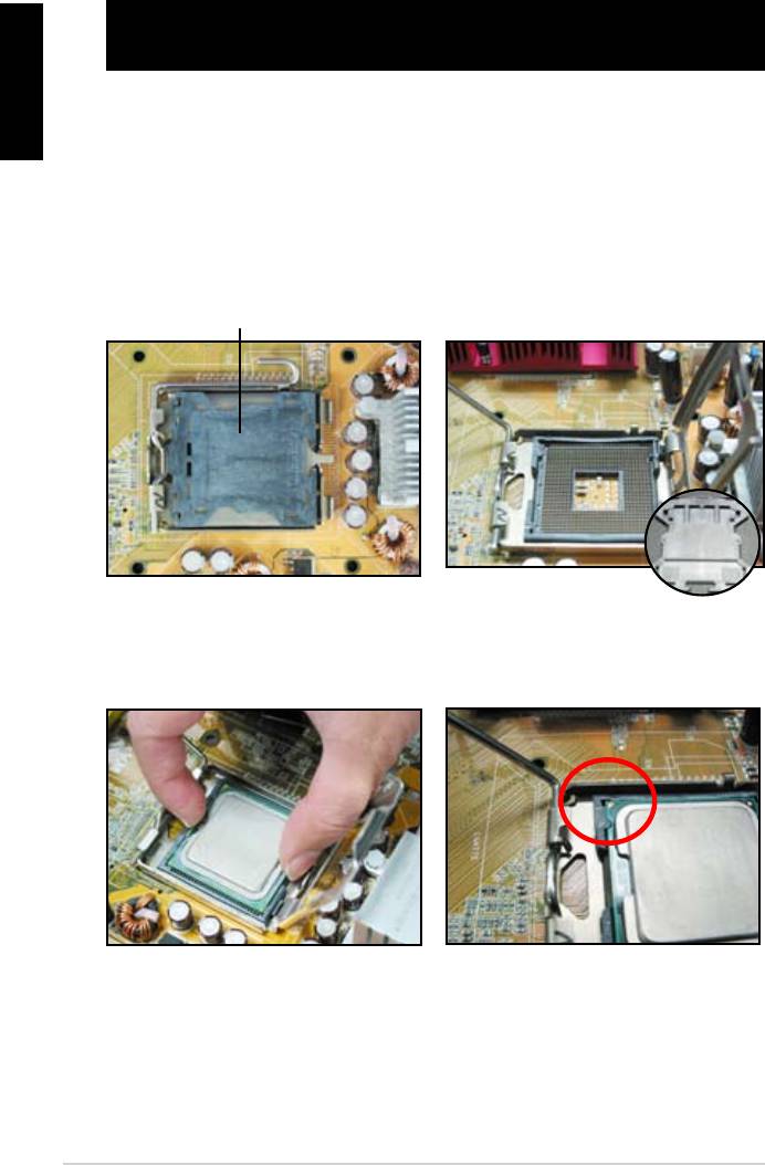
The socket alignment key should fit into the CPU notch. ASUS P5GC-MX This side of the cam box should face you. Load plate Alignment key Gold triangle mark… -
Page 22
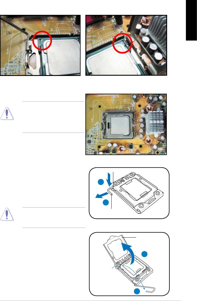
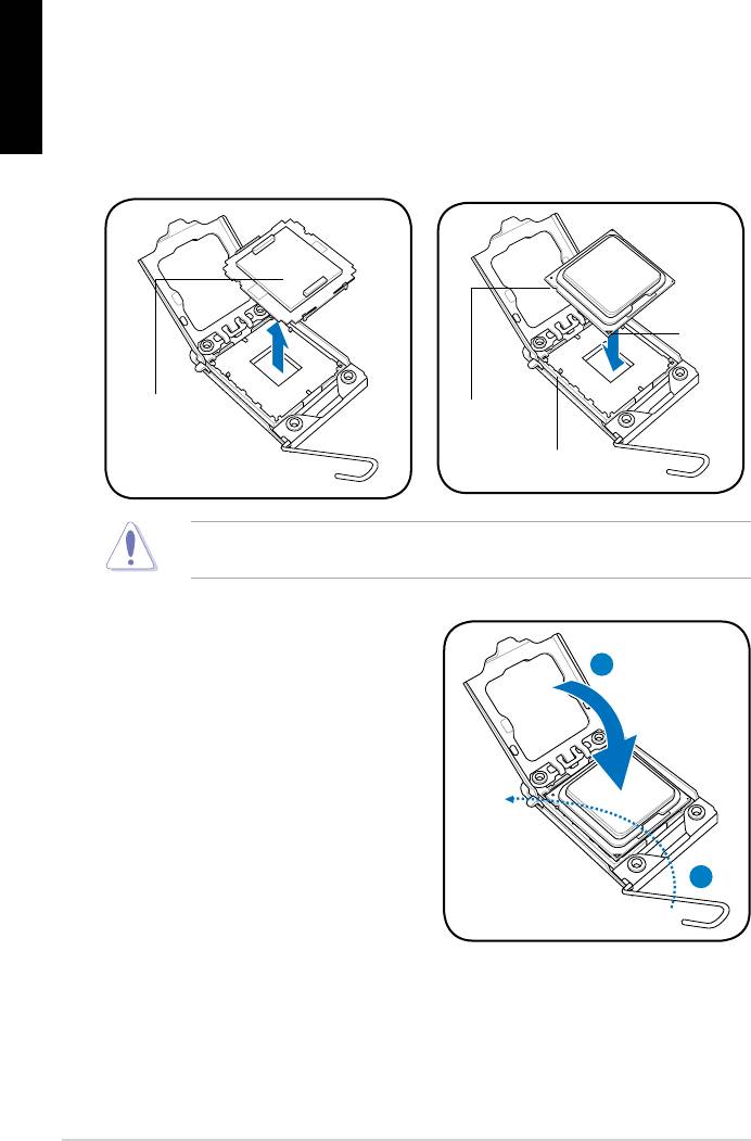
Close the load plate (A), then push the load lever (B) until it snaps into the retention tab. The CPU fits in only one correct orientation. DO NOT force the CPU into the socket to prevent bending the connectors on the socket and damaging the CPU! The motherboard supports Intel Enhanced Memory 64 Technology (EM64T), Enhanced Intel SpeedStep… -
Page 23: Installling The Cpu Heatsink And Fan
CPU, making sure that the four fasteners match the holes on the motherboard. Motherboard hole Make sure each fastener is oriented as shown, with the narrow groove directed outward. ASUS P5GC-MX D/Pentium 4 and Celeron ® ® Core™2 Duo/Pentium ®…
-
Page 24
Push down two fasteners at a time in a diagonal sequence to secure the heatsink and fan assembly in place. When the fan and heatsink assembly is in place, connect the CPU fan cable to the connector on the motherboard labeled CPU_FAN. P5GC-MX CPU Fan Connector •… -
Page 25: Uninstalling The Cpu Heatsink And Fan
To uninstall the CPU heatsink and fan: Disconnect the CPU fan cable from the connector on the motherboard. Rotate each fastener counterclockwise. Pull up two fasteners at a time in a diagonal sequence to disengage the heatsink and fan assembly from the motherboard. ASUS P5GC-MX 1-13…
-
Page 26
Remove the heatsink and fan assembly from the motherboard. Rotate each fastener clockwise to reset the orientation. The narrow end of the groove should point outward after resetting. (The photo shows the groove shaded for emphasis.) 1-14 Narrow end of the groove Chapter 1: Product introduction… -
Page 27: System Memory
Refer to the DDR2 Qualified Vendors List on next page for details. • This motherboard does not support memory modules made up of 128 Mb chips or double-sided x16 memory modules. . ASUS P5GC-MX Sockets DIMM_A1 DIMM_B1 1-15…
-
Page 28: Ddr2 Qualified Vendors List
DDR2 Qualified Vendors List The following table lists the memory modules that have been tested and qualified for use with this motherboard. Visit the ASUS website (www.asus. com) for the latest DDR2 DIMM modules for this motherboard. DDR2 533 Qualified Vendors List…
-
Page 29: Installing A Dimm
Support the DIMM lightly with your fingers when pressing the retaining clips. The DIMM might get damaged when it flips out with extra force. Remove the DIMM from the socket. ASUS P5GC-MX DDR2 DIMM notch Unlocked retaining clip DDR2 DIMM notch 1-17…
-
Page 30: Expansion Slots
Expansion slots In the future, you may need to install expansion cards. The following sub-sections describe the slots and the expansion cards that they support. Make sure to unplug the power cord before adding or removing expansion cards. Failure to do so may cause you physical injury and damage motherboard components.
-
Page 31: Interrupt Assignments
When using PCI cards on shared slots, ensure that the drivers support “Share IRQ” or that the cards do not need IRQ assignments. Otherwise, conflicts will arise between the two PCI groups, making the system unstable and the card inoperable. ASUS P5GC-MX — shared —…
-
Page 32: Pci Slots
1.8.4 PCI slots The PCI slots support cards such as a LAN card, SCSI card, USB card, and other cards that comply with PCI specifications. The figure shows a LAN card installed on a PCI slot. If you install a PCI graphics card, we recommend that you remove the onboard graphics card driver.
-
Page 33: Clear Rtc Ram
Hold down the <Del> key during the boot process and enter BIOS setup to re-enter data. Except when clearing the RTC RAM, never remove the cap on CLRTC jumper default position. Removing the cap will cause system boot failure! Clear RTC RAM P5GC-MX ASUS P5GC-MX CLRTC Normal Clear RTC (Default) 1-21…
-
Page 34
USB device wake-up (3-pin PS2_USBPWR) This jumper allows you to enable or disable the keyboard wake-up feature. Set this jumper to pins 2-3 (+5VSB) to wake up the computer when you press a key on the keyboard (the default is the Space Bar). This feature requires an ATX power supply that can supply at least 500 mA on the +5VSB lead, and a corresponding setting in the BIOS. -
Page 35: 1.10 Connectors
Front Speaker Out. Microphone port (pink). This port connects a microphone. Refer to the audio configuration table on the next page for the function of the audio ports in 2, 4, or 6-channel configuration. ASUS P5GC-MX SPEED LED Status Description…
-
Page 36: 1.10.2 Internal Connectors
Audio 2, 4, or 6-channel configuration Port Light Blue Lime Pink USB 2.0 ports 3 and 4. These two 4-pin Universal Serial Bus (USB) ports are available for connecting USB 2.0 devices. USB 2.0 ports 1 and 2. These two 4-pin Universal Serial Bus (USB) ports are available for connecting USB 2.0 devices.
-
Page 37: Ide Connector
IDE cable. • Use the 80-conductor IDE cable for Ultra DMA 100/66/33 IDE devices. If any device jumper is set as “Cable-Select,” make sure all other device jumpers have the same setting. ASUS P5GC-MX Mode Cable of device(s) connector Black…
-
Page 38: Serial Ata Connectors
Serial ATA connectors (7-pin SATA1, SATA2, SATA3, SATA4) These connectors are for the Serial ATA signal cables for Serial ATA hard disk drives. P5GC-MX SATA Connectors When using the connectors in Standard IDE mode, connect the primary (boot) hard disk drive to the SATA1/2 connector. Refer to the table below for the recommended SATA hard disk drive connections.
-
Page 39: Cpu And Chassis Fan Connectors
This connector is for the S/PDIF audio module to allow digital sound output. Connect one end of the S/PDIF audio cable to this connector and the other end to the S/PDIF module. P5GC-MX Digital Audio Connector The S/PDIF out module is purchased separately. ASUS P5GC-MX CPU_FAN CHA_FAN CPU FAN PWR +12V…
-
Page 40: Atx Power Connectors
ATX power connectors (24-pin EATXPWR and 4-pin ATX12V) These connectors are for ATX power supply plugs. The power supply plugs are designed to fit these connectors in only one orientation. Find the proper orientation and push down firmly until the connectors completely fit.
-
Page 41: Optical Drive Audio/Usb Connectors
USB 2.0 specification that supports up to 480 Mbps connection speed. P5GC-MX USB 2.0 Connectors Never connect a 1394 cable to the USB connectors. Doing so will damage the motherboard! The USB module is purchased separately. ASUS P5GC-MX (black) USB56 USB78 1-29…
-
Page 42: Front Panel Audio Connector
Front panel audio connector (10-1 pin AAFP) This connector is for a chassis-mounted front panel audio I/O module that supports either HD Audio or legacy AC’97 audio standard. P5GC-MX Front Panel Audio Connector • We recommend that you connect a high-definition front panel audio module to this connector to avail of the motherboard’s high- definition audio capability.
-
Page 43: System Panel Connector
ON turns the system OFF. • Reset button (2-pin RESET) This 2-pin connector is for the chassis-mounted reset button for system reboot without turning off the system power. ASUS P5GC-MX F_PANEL Reset Ground PLED-…
-
Page 44
1-32 Chapter 1: Product introduction… -
Page 45: Chapter 2: Bios Setup
This chapter tells how to change the system settings through the BIOS Setup menus. Detailed descriptions of the BIOS parameters are also provided. BIOS setup…
-
Page 46: Managing And Updating Your Bios
The following utilities allow you to manage and update the motherboard Basic Input/Output System (BIOS) setup. ASUS EZ Flash (Updates the BIOS in DOS using a floppy disk or the motherboard support CD.) ASUS AFUDOS (Updates the BIOS in DOS mode using a bootable floppy disk.)
-
Page 47: To Update Bios Using Ez Flash
2.1.2 ASUS EZ Flash utility The ASUS EZ Flash feature allows you to update the BIOS without having to go through the long process of booting from a floppy disk and using a DOS-based utility. The EZ Flash utility is built-in the BIOS chip so it is accessible by pressing <Alt>…
-
Page 48: Copying Current Bios
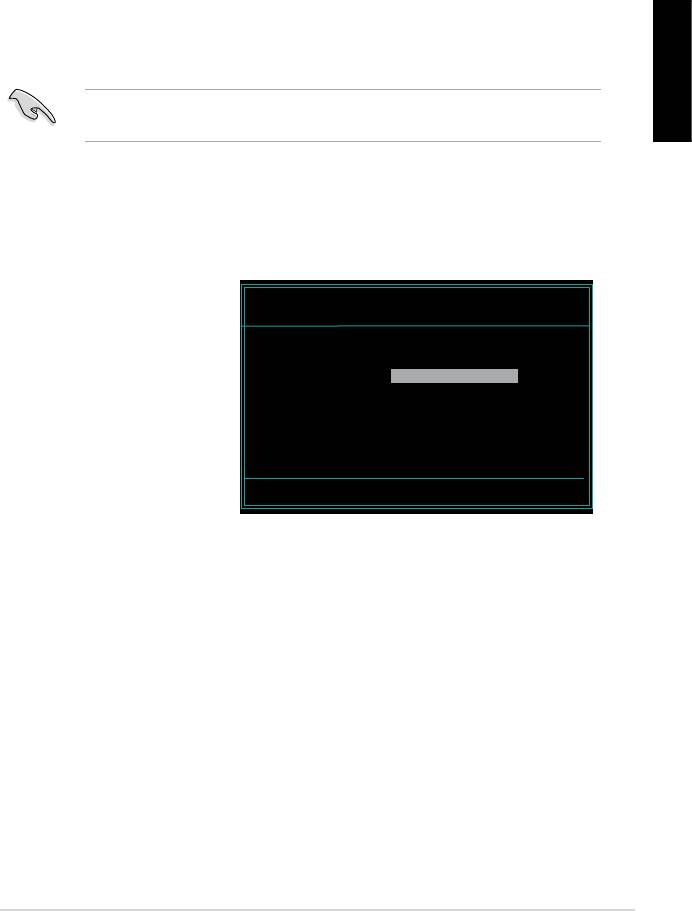
Press <Enter>. The utility copies the current BIOS file to the floppy disk. A:>afudos /oOLDBIOS1.rom AMI Firmware Update Utility — Version 1.19(ASUS V2.07(03.11.24BB)) Copyright (C) 2002 American Megatrends, Inc. All rights reserved. Reading flash … done Write to file… ok A:>…
-
Page 49: Updating The Bios File
Updating the BIOS file To update the BIOS file using the AFUDOS utility: Visit the ASUS website (www.asus.com) and download the latest BIOS file for the motherboard. Save the BIOS file to a bootable floppy disk. Write the BIOS filename on a piece of paper. You need to type the exact BIOS filename at the DOS prompt.
-
Page 50: Asus Crashfree Bios 2 Utility
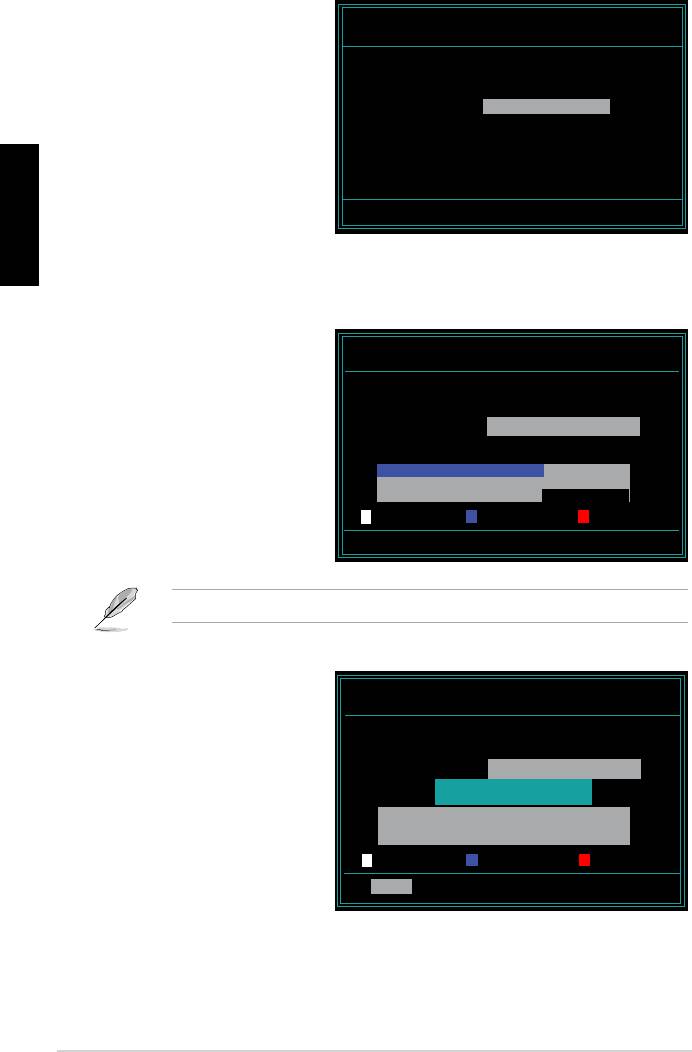
2.1.4 ASUS CrashFree BIOS 2 utility The ASUS CrashFree BIOS 2 is an auto recovery tool that allows you to restore the BIOS file when it fails or gets corrupted during the updating process. You can update a corrupted BIOS file using the motherboard support CD, or the floppy disk that contains the updated BIOS file.
-
Page 51: Recovering The Bios From The Support Cd
Restart the system after the utility completes the updating process. The recovered BIOS may not be the latest BIOS version for this motherboard. Visit the ASUS website (www.asus.com) to download the latest BIOS file. ASUS P5GC-MX…
-
Page 52: Asus Update Utility
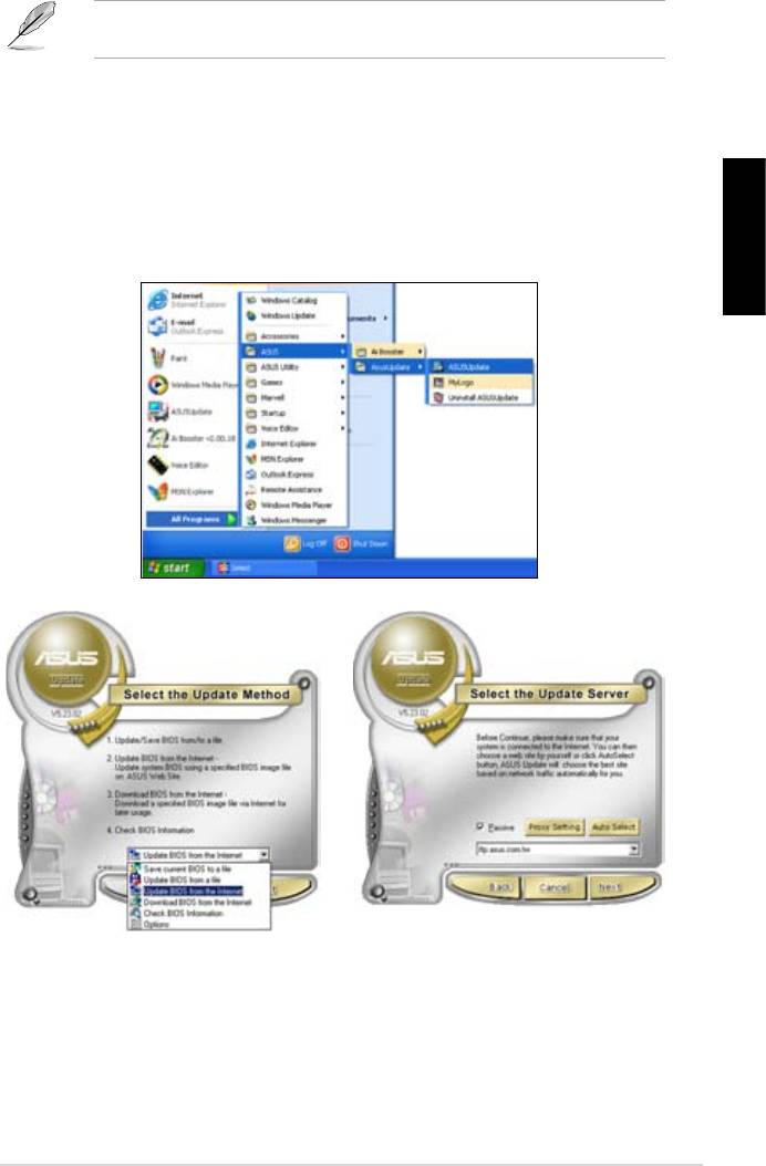
2.1.5 ASUS Update utility The ASUS Update is a utility that allows you to manage, save, and update the motherboard BIOS in Windows allows you to: • Save the current BIOS file • Download the latest BIOS file from the Internet •…
-
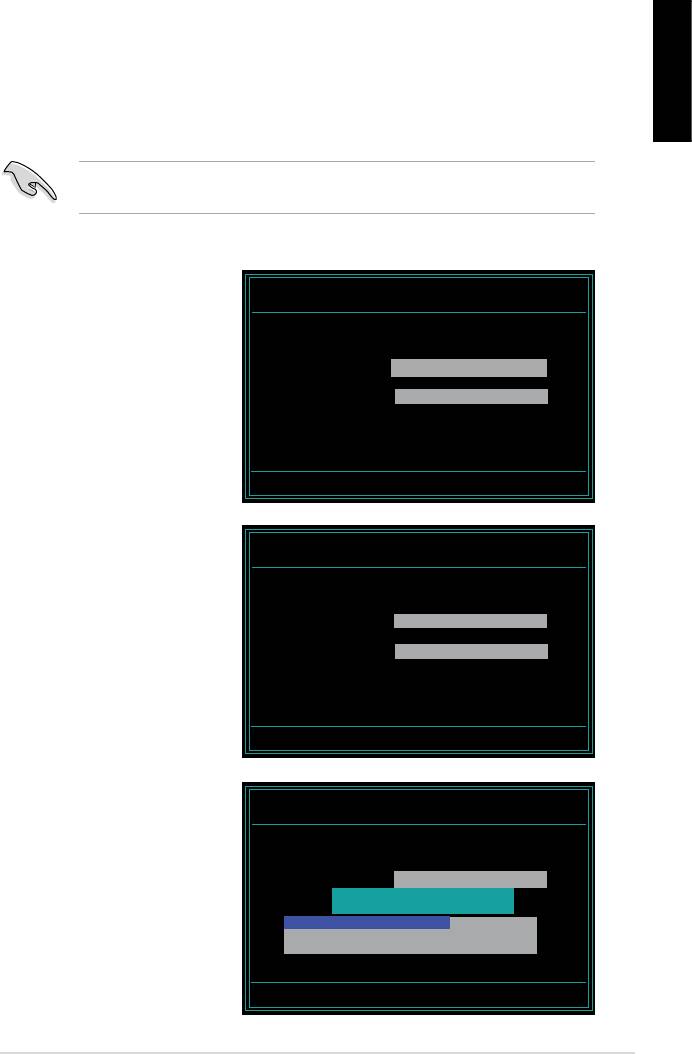
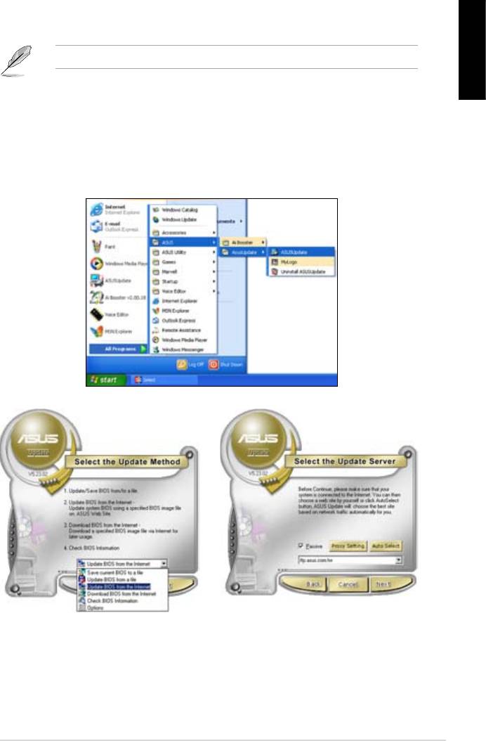
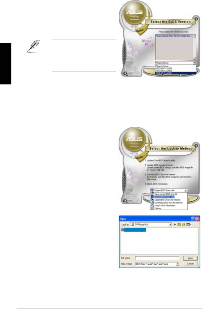
Page 53: Updating The Bios Through The Internet
Updating the BIOS through the Internet To update the BIOS through the Internet: Launch the ASUS Update utility from the Windows Start > Programs > ASUS > ASUSUpdate > ASUSUpdate. The ASUS Update main window appears. Select Update BIOS from…
-
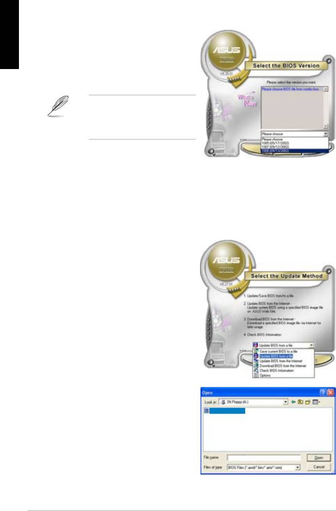
Page 54: Updating The Bios Through A Bios File
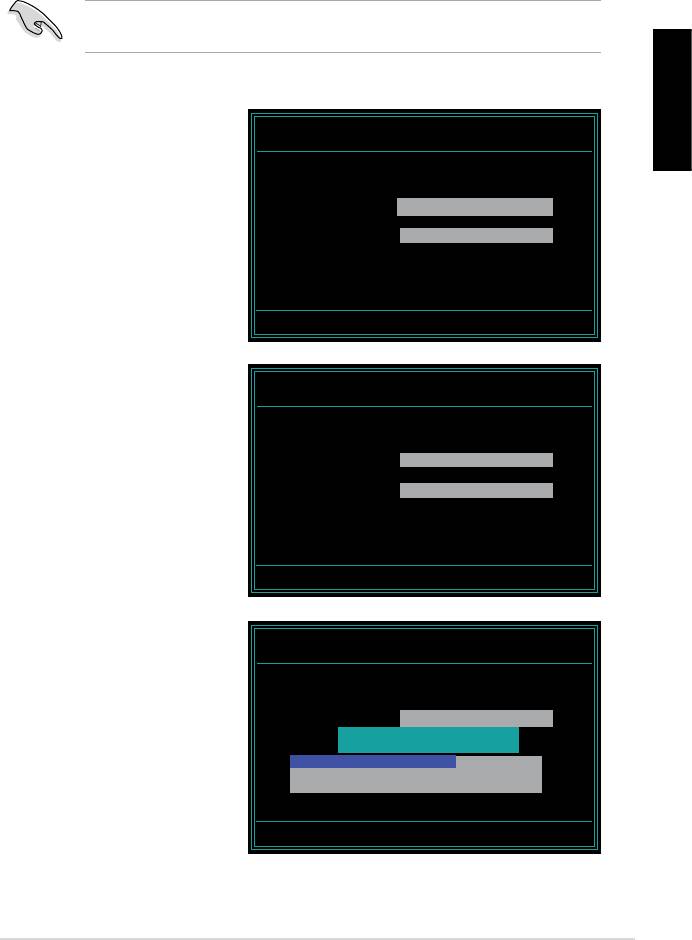
Updating the BIOS through a BIOS file To update the BIOS through a BIOS file: Launch the ASUS Update utility from the Windows clicking Start > Programs > ASUS > ASUSUpdate > ASUSUpdate. The ASUS Update main window appears. Select Update BIOS from a file option from the drop-down menu, then click Next.
-
Page 55: Bios Setup Program
The BIOS setup screens shown in this section are for reference purposes only, and may not exactly match what you see on your screen. • Visit the ASUS website (www.asus.com) to download the latest BIOS file for this motherboard. ASUS P5GC-MX 2-11…
-
Page 56: Bios Menu Screen
2.2.1 BIOS menu screen Menu items Menu bar System Time System Date Legacy Diskette A Primary IDE Master Primary IDE Slave Third IDE Master Third IDE Slave Fourth IDE Master Fourth IDE Slave IDE Configuration System Information Sub-menu items 2.2.2 Menu bar The menu bar on top of the screen has the following main items: Main…
-
Page 57: Menu Items
2.2.9 General help At the top right corner of the menu screen is a brief description of the selected item. ASUS P5GC-MX System Time [11:10:19] Use [ENTER], [TAB] System Date [Thu 03/27/2003] or [SHIFT-TAB] to Legacy Diskette A [1.44M, 3.5 in]…
-
Page 58: Main Menu
Main menu When you enter the BIOS Setup program, the Main menu screen appears, giving you an overview of the basic system information. Refer to section “2.2.1 BIOS menu screen” for information on the menu screen items and how to navigate through them. System Time System Date Legacy Diskette A…
-
Page 59: Primary, Third And Fourth Ide Master/Slave
When set to [Disabled], the data transfer from and to the device occurs one sector at a time. Configuration options: [Disabled] [Auto] ASUS P5GC-MX [Auto] [Auto] [Auto]…
-
Page 60: Ide Configuration
PIO Mode [Auto] Selects the PIO mode. Configuration options: [Auto] [0] [1] [2] [3] [4] DMA Mode [Auto] Selects the DMA mode. Configuration options: [Auto] SMART Monitoring [Auto] Sets the Smart Monitoring, Analysis, and Reporting Technology. Configuration options: [Auto] [Disabled] [Enabled] 32Bit Data Transfer [Disabled] Enables or disables 32-bit data transfer.
-
Page 61: System Information
: Genuine Intel(R) CPU 3.80GHz Speed : 3800MHz Count System Memory Total : 256MB Appropriated : 8MB Available : 248MB AMI BIOS Displays the auto-detected BIOS information Processor Displays the auto-detected CPU specification System Memory Displays the auto-detected system memory ASUS P5GC-MX 2-17…
-
Page 62: Advanced Menu
Advanced menu The Advanced menu items allow you to change the settings for the CPU and other system devices. Take caution when changing the settings of the Advanced menu items. Incorrect field values can cause the system to malfunction. USB Configuration CPU Configuration Chipset Onboard Devices Configuration…
-
Page 63: Usb Mass Storage Device Configuration
USB devices less than 530MB will be emulated as Floppy remaining as hard drive, and forced FDD option can be used to force a HDD formatted drive to boot as FDD. Configuration options: [Auto] [Floppy] [Forced FDD] [Hard Disk] [CDROM] ASUS P5GC-MX [20 Sec] [Auto] 2-19…
-
Page 64: Cpu Configuration
2.4.2 CPU Configuration The items in this menu show the CPU-related information that the BIOS automatically detects. Configure advanced CPU settings Manufacturer: Intel Brand String: Genuine Intel(R) CPU 3.80GHz Frequency : 3800MHz FSB Speed : 1085MHz Cache L1 : 16 KB Cache L2 : 2048 KB Cache L3…
-
Page 65: Chipset
Graphics memory type Boot Display Device TV Connector HDTV Output TV Standard PEG Buffer Length Link Latency PEG Root Control Slot Power High Priority Port Select ASUS P5GC-MX Technology. When set ® [Auto] [Enabled] [Auto] [Auto] [PCI Express/Int-VG] [Enabled, 8MB] [Auto]…
-
Page 66
DRAM Frequency [Auto] Allows you to set the DDR2 operating frequency. Configuration options: [Auto] [400 Mhz] [533 Mhz] Selecting a very high DRAM frequency may cause the system to become unstable! If this happens, revert to the default setting. Configure DRAM Timing by SPD [Enabled] When this item is enabled, the DRAM timing parameters are set according to the DRAM SPD (Serial Presence Detect). -
Page 67
Sets PCIEX graphics card buffer length. Configuration options: [Auto] [Long] [Short] Link Latency [Auto] Sets link latency. Configuration options: [Auto] [Slow] [Normal] PEG Root Control [Auto] Enables, disables or set to Auto of the link latency. Configuration options: [Auto] [Disabled] [Enabled] ASUS P5GC-MX 2-23… -
Page 68: Onboard Devices Configuration
Slot Power [Auto] Sets the slot power. Configuration options: [Auto] [Light] [Normal] [Heavy] [Heavier] High Priority Port Select [Disabled] Selects the high priority port. Configuration options: [Disabled] [PCI Express Port 2] 2.4.4 Onboard Devices Configuration Configure Win627DHG Super IO Chipset HD Audio Controller Front Panel Support Type Onboard PCIEX 10/100Mb LAN…
-
Page 69
ECP Mode DMA Channel [DMA3] Appears only when the Parallel Port Mode is set to [ECP]. This item allows you to set the Parallel Port ECP DMA. Configuration options: [DMA0] [DMA1] [DMA3] Parallel Port IRQ [IRQ7] Configuration options: [IRQ5] [IRQ7] ASUS P5GC-MX 2-25… -
Page 70: Pci Pnp
2.4.5 PCI PnP The PCI PnP menu items allow you to change the advanced settings for PCI/PnP devices. The menu includes setting IRQ and DMA channel resources for either PCI/PnP or legacy ISA devices, and setting the memory size block for legacy ISA devices.
-
Page 71: Power Menu
Allows you to enable or disable the Advanced Configuration and Power Interface (ACPI) support in the Application-Specific Integrated Circuit (ASIC). When set to Enabled, the ACPI APIC table pointer is included in the RSDT pointer list. Configuration options: [Disabled] [Enabled] ASUS P5GC-MX Configure CPU. [Auto] [Disabled]…
-
Page 72: Apm Configuration
2.5.4 APM Configuration APM Configuration Power Button Mode Restore on AC Power Loss Power On By RTC Alarm RTC Alarm Date RTC Alarm Hour RTC Alarm Minute RTC Alarm Second Power On By External Modems Power On By PCI Devices Power On By PCIE Devices Power On By PS/2 Keyboard Power On By PS/2 Mouse…
-
Page 73
When set to [Enabled], this parameter allows you to use the PS/2 mouse to turn on the system. This feature requires an ATX power supply that provides at least 1A on the +5VSB lead. Configuration options: [Disabled] [Enabled] ASUS P5GC-MX 2-29… -
Page 74: Hardware Monitor
N/A. Configuration options: [Ignored] [xxxRPM] CPU Q-Fan Control [Disabled] Allows you to enable or disable the ASUS Q-Fan feature that smartly adjusts the fan speeds for more efficient system operation. Configuration options: [Disabled] [Enabled] Chassis Fan Speed [xxxxRPM] or [N/A] or [Ignored] The onboard hardware monitor automatically detects and displays the chassis fan speed in rotations per minute (RPM).
-
Page 75: Boot Menu
These items specify the boot device priority sequence from the available devices. The number of device items that appears on the screen depends on the number of devices installed in the system. Configuration options: [xxxxx Drive] [Disabled] ASUS P5GC-MX Enter Go to Sub-screen [1st FLOPPY DRIVE] [Hard Drive]…
-
Page 76: Boot Settings Configuration
This allows you to enable or disable the full screen logo display feature. Configuration options: [Disabled] [Enabled] Set this item to [Enabled] to use the ASUS MyLogo™ feature. Add On ROM Display Mode [Force BIOS] Sets the display mode for option ROM.
-
Page 77: Security
If you forget your BIOS password, you can clear clear it by erasing the CMOS Real Time Clock (RTC) RAM. See section “2.6 Jumpers” for information on how to erase the RTC RAM. ASUS P5GC-MX <Enter> to change password. <Enter> again to disabled password.
-
Page 78: Change User Password
After you have set a supervisor password, the other items appear to allow you to change other security settings. Security Settings Supervisor Password User Password Change Supervisor Password User Access Level Change User Password Clear User Password Password Check User Access Level [Full Access] This item allows you to select the access restriction to the Setup items.
-
Page 79: Exit Menu
If you attempt to exit the Setup program without saving your changes, the program prompts you with a message asking if you want to save your changes before exiting. Press <Enter> to save the changes while exiting. ASUS P5GC-MX Exit system setup after saving the changes.
-
Page 80: Discard Changes
Exit & Discard Changes Select this option only if you do not want to save the changes that you made to the Setup program. If you made changes to fields other than System Date, System Time, and Password, the BIOS asks for a confirmation before exiting.
-
Page 81: Chapter 3: Software Support
This chapter describes the contents of the support CD that comes with the motherboard package. Software support…
-
Page 82: Installing An Operating System
The contents of the support CD are subject to change at any time without notice. Visit the ASUS website(www.asus.com) for updates. 3.2.1 Running the support CD Place the support CD to the optical drive.
-
Page 83: Drivers Menu
Refer to the online help or readme file that came with the utility for details. Intel Graphics Accelerator Driver Installs the Intel Graphics Accelerator driver. Realtek Audio Driver Installs the Realtek Audio driver. Attansic L2 Fast Ethernet Installs the Attansic L2 Fast Ethernet. ASUS P5GC-MX…
-
Page 84: Utilities Menu
ASUS Update The ASUS Update utility allows you to update the motherboard BIOS in a Windows® environment. This utility requires an Internet connection either through a network or an Internet Service Provider (ISP).
-
Page 85: Asus Contact Information
Corel Snapfire Plus SE Installs the Corel Snapfire Plus SE software. 3.2.4 ASUS Contact information Click the Contact tab to display the ASUS contact information. You can also find this information on the inside front cover of this user guide. ASUS P5GC-MX…
-
Page 86
Chapter 3: Software support… -
Page 87: Cpu Features
The Appendix describes the CPU features that the motherboard supports. CPU features…
-
Page 88: Appendix: Cpu Features
32-bit operating systems. • The motherboard comes with a BIOS file that supports EM64T. You can download the latest BIOS file from the ASUS website (www.asus. com/support/download/) if you need to update the BIOS file. See Chapter 2 for details.
-
Page 89: Using The Eist
Click Apply, then click OK. 10. Close the Display Properties window. After you adjust the power scheme, the CPU internal frequency slightly decreases when the CPU loading is low. The screen displays and procedures may vary depending on the operating system. ASUS P5GC-MX…
-
Page 90: Intel ® Hyper-Threading Technology
Intel • The motherboard supports Intel with Hyper-Threading Technology. • Hyper-Threading Technology is supported under Windows Linux 2.4.x (kernel) and later versions only. Under Linux, use the Hyper-Threading compiler to compile the code. If you are using any other operating systems, disable the Hyper-Threading Techonology item in the BIOS to ensure system stability and performance.
-
Драйверы
38
-
Инструкции по эксплуатации
12
Языки:

ASUS P5GC-MX/1333 инструкция по эксплуатации
(92 страницы)
- Языки:Английский
-
Тип:
PDF -
Размер:
2.91 MB -
Описание:
P5GC-MX/1333 user’s manual(English)
Просмотр

ASUS P5GC-MX/1333 инструкция по эксплуатации
(40 страниц)
- Языки:Молдавский, Немецкий
-
Тип:
PDF -
Размер:
1.65 MB -
Описание:
Motherboard Installation Guide (German)
Motherboard Installation Guide (German)
Просмотр

ASUS P5GC-MX/1333 инструкция по эксплуатации
(92 страницы)
- Языки:Китайский
-
Тип:
PDF -
Размер:
2.35 MB -
Описание:
P5GC-MX/1333 user’s manual(Simplified Chinese)
Просмотр

ASUS P5GC-MX/1333 инструкция по эксплуатации
(92 страницы)
- Языки:Китайский
-
Тип:
PDF -
Размер:
2.49 MB -
Описание:
P5GC-MX/1333 user’s manual (Traditional Chinese)
Просмотр

ASUS P5GC-MX/1333 инструкция по эксплуатации
(44 страницы)
- Языки:Китайский, Молдавский
-
Тип:
PDF -
Размер:
1.88 MB -
Описание:
Motherboard Installation Guide (Simplified Chinese)
Просмотр

ASUS P5GC-MX/1333 инструкция по эксплуатации
(44 страницы)
- Языки:Китайский, Молдавский
-
Тип:
PDF -
Размер:
2.02 MB -
Описание:
Motherboard Installation Guide (Traditional Chinese)
Просмотр

ASUS P5GC-MX/1333 инструкция по эксплуатации
(8 страниц)
- Языки:Китайский, Молдавский
-
Тип:
PDF -
Размер:
2.67 MB -
Описание:
Motherboard DIY Troubleshooting Guide (Traditional Chinese version)
Просмотр

ASUS P5GC-MX/1333 инструкция по эксплуатации
(40 страниц)
- Языки:Молдавский, Японский
-
Тип:
PDF -
Размер:
1.73 MB -
Описание:
Motherboard Installation Guide (Japanese)
Просмотр

ASUS P5GC-MX/1333 инструкция по эксплуатации
(40 страниц)
- Языки:Молдавский, Французский
-
Тип:
PDF -
Размер:
1.64 MB -
Описание:
Motherboard Installation Guide (French)
Просмотр

ASUS P5GC-MX/1333 инструкция по эксплуатации
(721 страница)
- Языки:Молдавский
-
Тип:
PDF -
Размер:
43.88 MB -
Описание:
Motherboard Installation Guide (Multiple Languages)
Просмотр

ASUS P5GC-MX/1333 инструкция по эксплуатации
(29 страниц)
-
Тип:
PDF -
Размер:
4.38 MB -
Описание:
P5GC-MX/1333 user’s manual(Multiple Languages)
Просмотр

ASUS P5GC-MX/1333 инструкция по эксплуатации
(38 страниц)
-
Тип:
PDF -
Размер:
1.81 MB -
Описание:
P5GC-MX/1333 Quick Start Guide for Multiple Languages
Просмотр
На NoDevice можно скачать инструкцию по эксплуатации для ASUS P5GC-MX/1333. Руководство пользователя необходимо для ознакомления с правилами установки и эксплуатации ASUS P5GC-MX/1333. Инструкции по использованию помогут правильно настроить ASUS P5GC-MX/1333, исправить ошибки и выявить неполадки.

Index
1. English ………………………………………………………………………1
2. Türkçe ……………………………………………………………………..41
3.
…………………………………………………………………..
81
4. …………………………………………………………………….121
…………………………………………………………………..161
6. Bahasa Indonesia ……………………………………………………
201
7. Italiano
……………………………………………………………………241
8.
한국어
……………………………………………………………………
281
9. Polski ……………………………………………………………………..321
10. Português ……………………………………………………………….361
………………………………………………………………….401
12.
……………………………………………………………………
441
13. Srpski …………………………………………………………………….481
14. Español ………………………………………………………………….521
15.
ไทย
………………………………………………………………………..
561
……………………………………………………………….
601
17. ……………………………………………………………………..641
18. ……………………………………………………………………..681

Motherboard
installation guide
Motherboard
E4204
September 2008
Copyright © 2008 ASUSTeK COMPUTER INC. All Rights Reserved.
permission of ASUSTeK COMPUTER INC. (“ASUS”).
product is defaced or missing.
Safety information
Electrical safety
•
•
power cables for the devices are unplugged before the signal cables are
•
Before connecting or removing signal cables from the motherboard, ensure
that all power cables are unplugged.
•
Seek professional assistance before using an adpater or extension cord.
These devices could interrupt the grounding circuit.
•
•
Operation safety
•
the manuals that came with the package.
•
•
•
•
Place the product on a stable surface.
•
English
Chapter 1: Quick Start
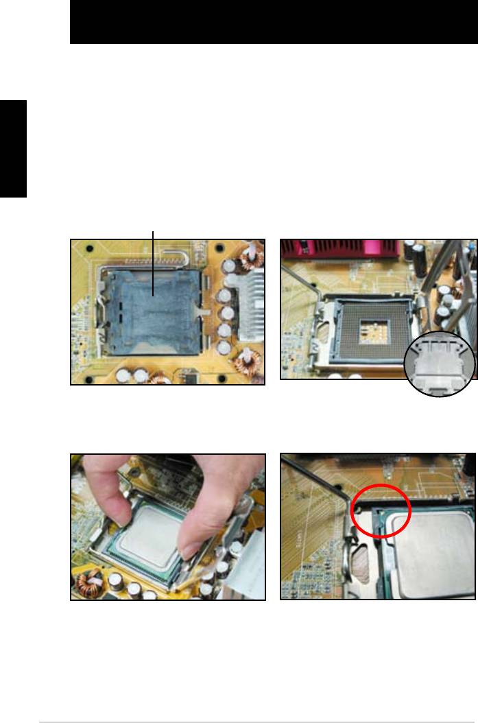
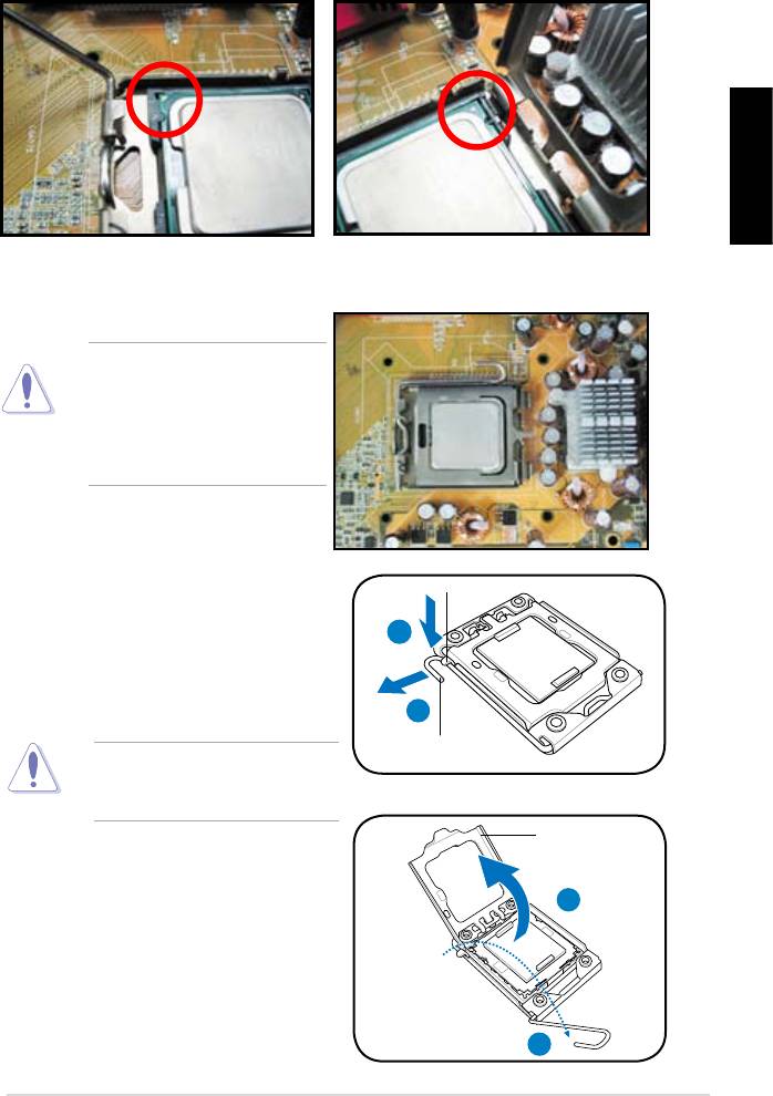
1.1 Installing the CPU
1.1.1 Intel LGA775 Socket
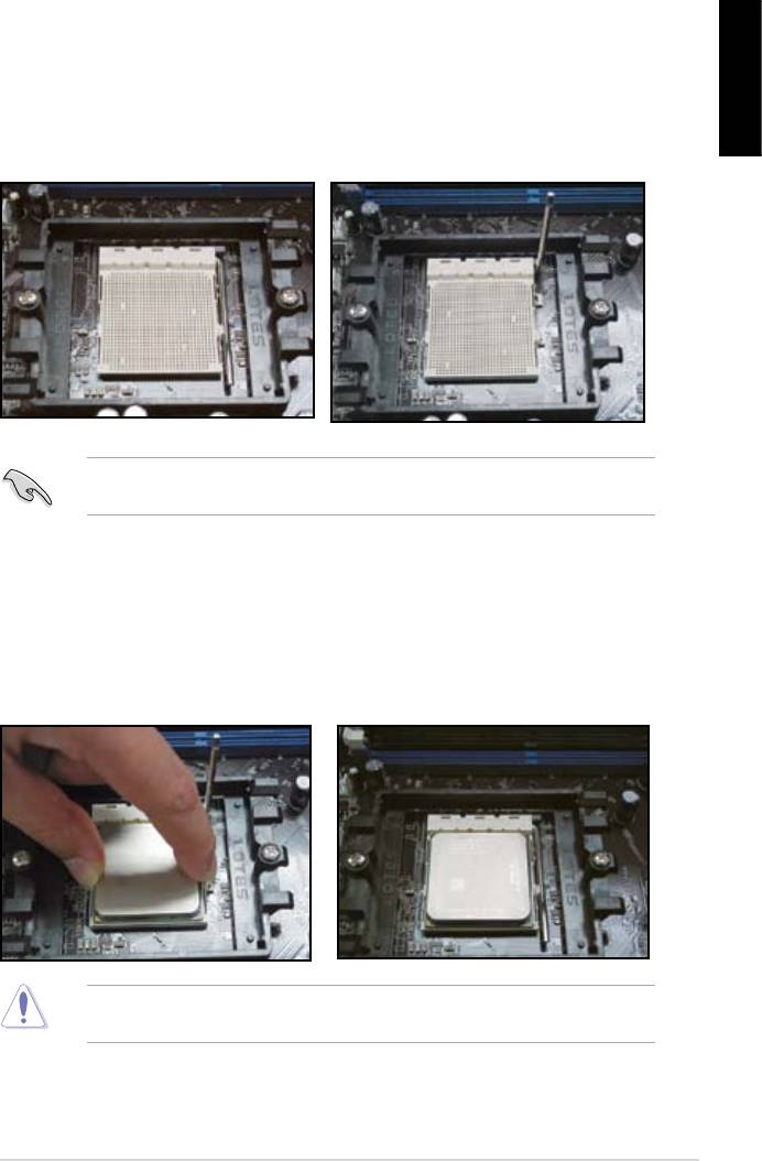
2. Release the load lever from the
motherboard.
retention tab and lift the load plate.
Then push the PnP cap from the
load plate window to remove
To prevent damage to the socket
pins, do not remove the PnP cap
Pick and Place Cap (PnP Cap)
4. Make sure that the gold triangle
3. Position the CPU over the socket.
is on the bottom‑left corner of the
socket.
4
English
6. Close the load plate, then push the load lever until it snaps into the retention
tab.
CPU into the socket to prevent
bending the connectors on the
socket and damaging the CPU!
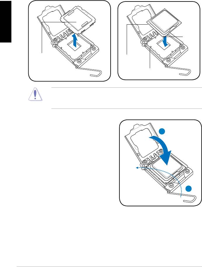
1.1.2 Intel LGA1366 Socket
Retention tab
motherboard.
A
thumb (A), then move it to the left
(B) until it is released from the
retention tab.
B
Load lever
To prevent damage to the socket
pins, do not remove the PnP cap
Load plate
the arrow to a 135º angle.
4
3
ASUS Motherboard installation guide 5
English
5. Remove the PnP cap from the CPU
6. Position the CPU over the socket,
socket.
making sure that the gold triangle
is on the bottom‑left corner of the
Gold
triangle
mark
PnP cap
CPU notch
Alignment key
socket to prevent bending the connectors on the socket and damaging the CPU!
8. Close the load plate (A), and then
push the load lever (B) until it snaps
A
into the retention tab.
B
6
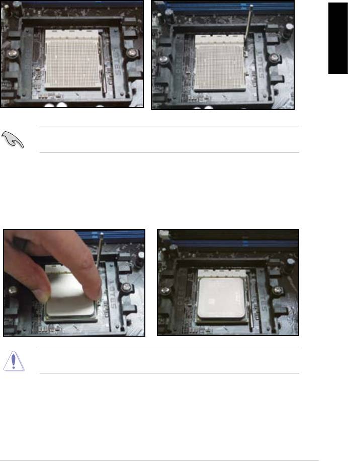
1.1.3 AMD AM2 Socket
English
motherboard.
the socket, then lift it up to a 90º
angle.
Make sure that the socket lever is lifted up to 90º angle. Otherwise, the CPU will
3. Position the CPU above the socket
such that the CPU corner with the
down the socket lever to secure the
gold triangle matches the socket
CPU. The lever clicks on the side tab
corner with a small triangle.
to indicate that it is locked.
socket to prevent bending the connectors on the socket and damaging the CPU!
ASUS Motherboard installation guide 7
English
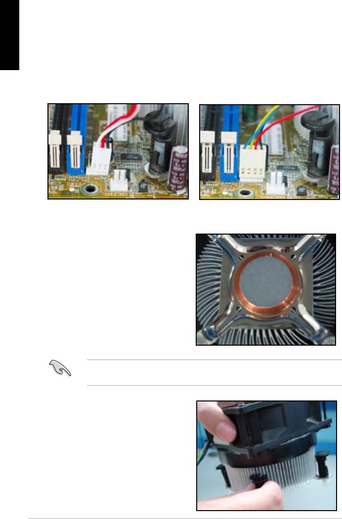
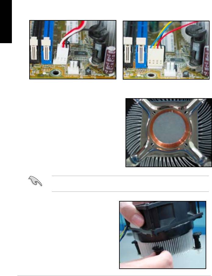
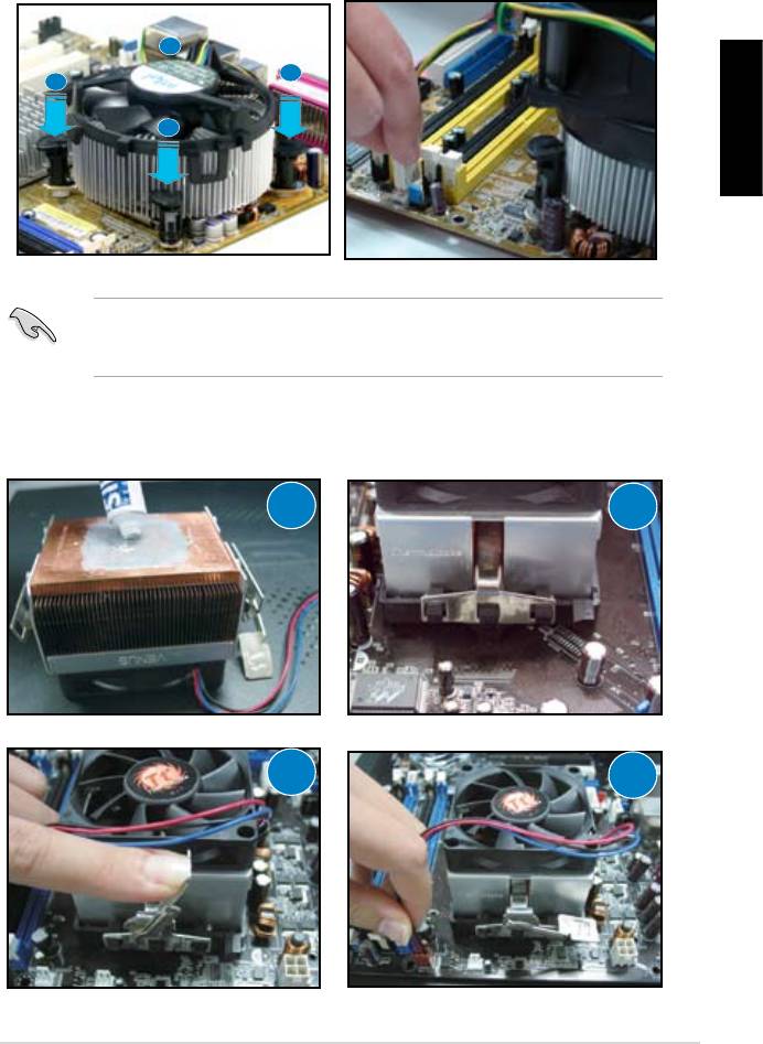
1.2 Installing the heatsink and fan
For Intel-certied heatsink:
2. Some heatsinks will come with
pre‑applied thermal paste. If so,
do not scrape it off and remove
installation. If not, before installing
thermal paste to the exposed area
of the CPU that the heatsink will be
in contact with. Make sure that it is
3. Orient each fastener with the
narrow end of the groove pointing
outward.
8
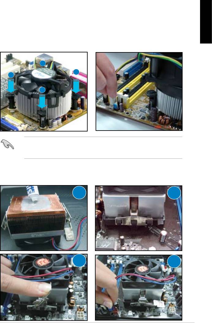
4. Push down two fasteners at a time
5. Connect the CPU fan cable to the
in a diagonal sequence to secure
corresponding connector on the
English
motherboard.
place.
B
A
A
B
directional heatsink to gain the maximum heat dissipation area.
For AMD-certied heatsink:
1
2
3
4
ASUS Motherboard installation guide 9
English
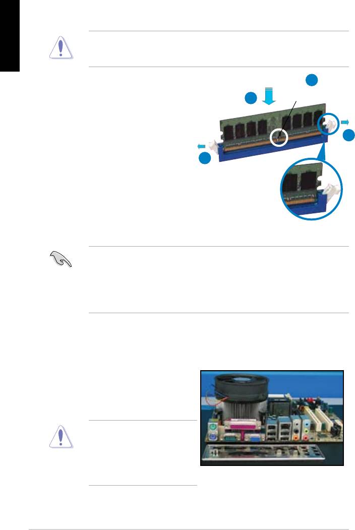
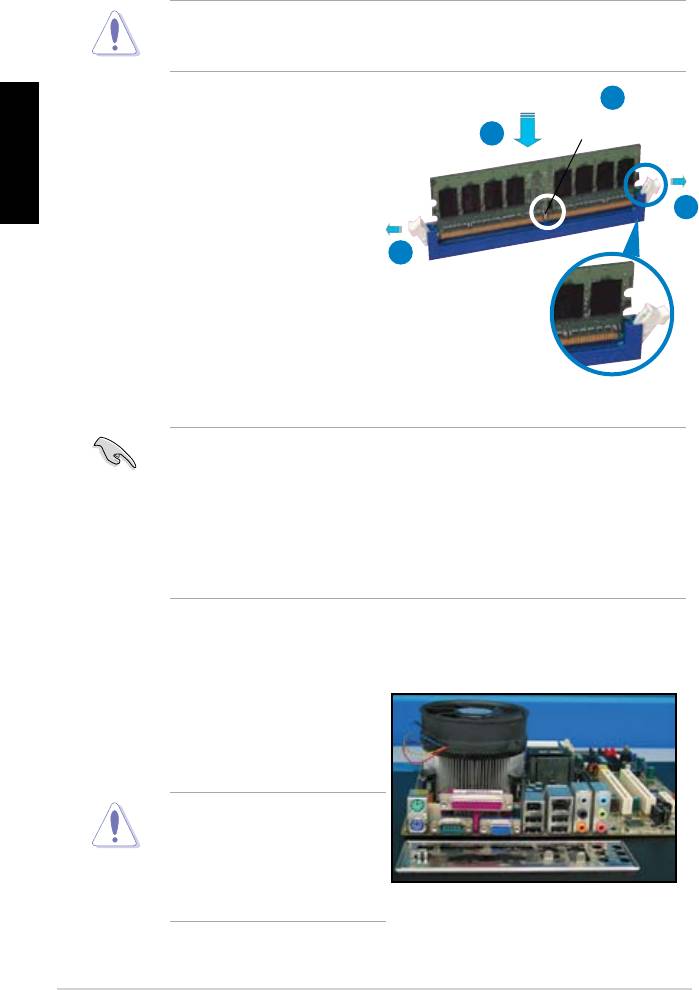
1.3 Installing a DIMM
motherboard and the components.
2
DDR2 DIMM notch
3
1. Press the retaining clips outward
1
matches the break on the socket.
1
socket until the retaining clips
Unlocked retaining clip
motherboard package.
1.4 Installing the motherboard
1. I/O ports differ with motherboards.
Use and install the rear I/O shield
that comes with the motherboard
Some sharp edges and points
puncture resistant gloves before
motherboard and I/O shield
installation.
10
2. Install the standoffs to the matched
screw holes on the metal plate.
damage the I/O ports. Be cautious
English
when installing the I/O shield.
4. Position the I/O side of the
motherboard toward the rear of the
After all the screws have been
chassis and place the motherboard
inserted, drive the screws until
into the chassis.
of the chassis before installing the motherboard. For some chassis models,
ASUS Motherboard installation guide 11
1.5 Installing the power supply unit
English
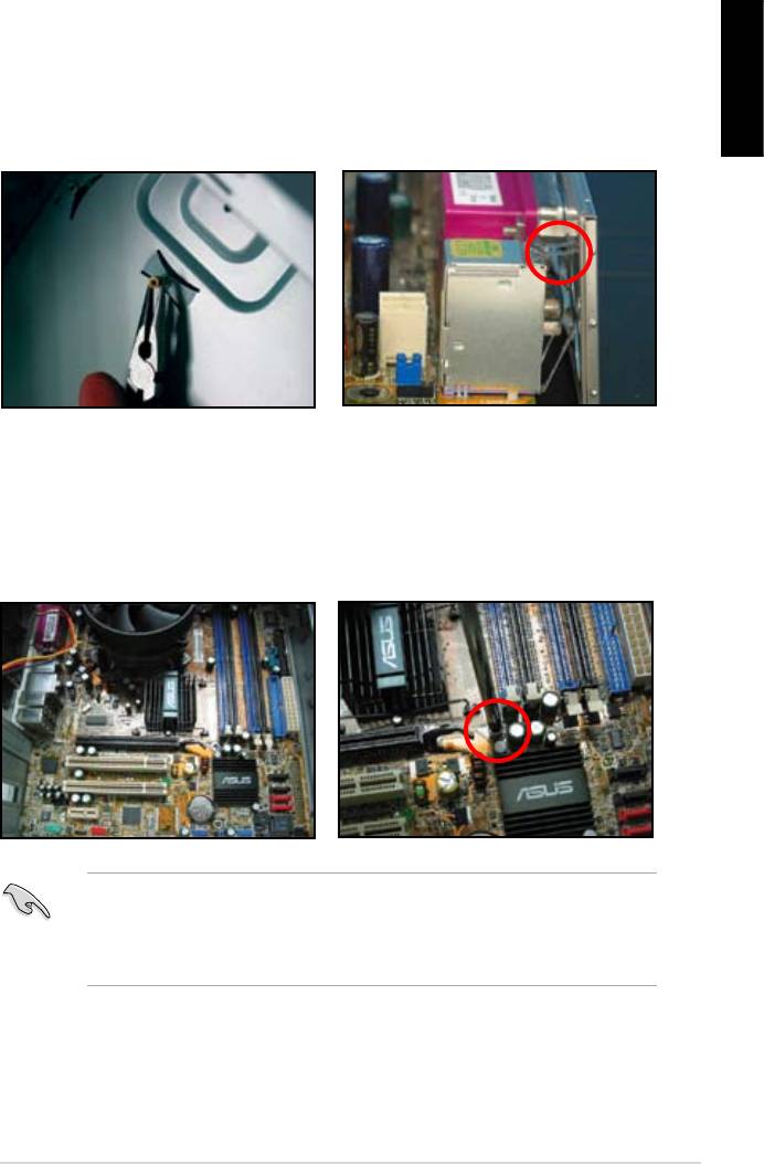
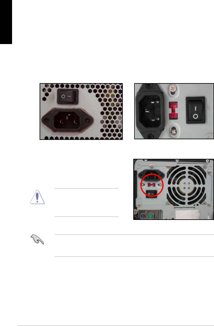
Power Factor Correction (PFC) and the other with passive PFC.
Power supply with active PFC:
Power supply with passive PFC:
Passive PFC requires user to
the AC input voltage.
voltage.
area.
12
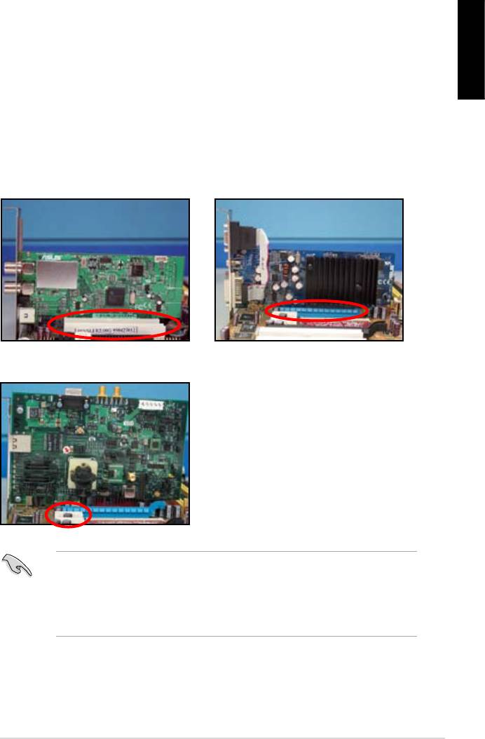
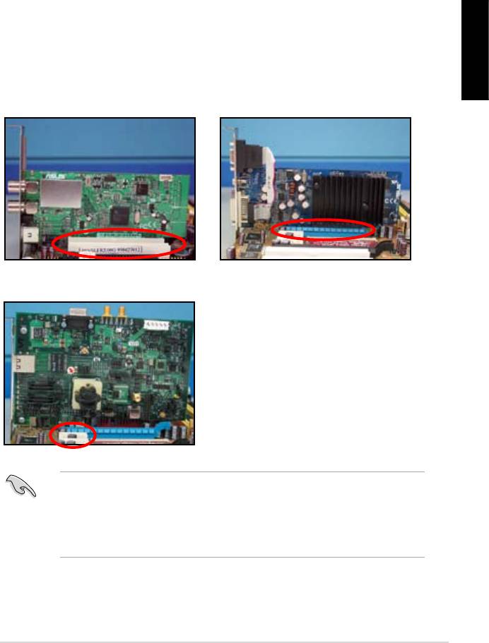
1.6 Installing an expansion card
English
wish to install an expansion card.
3. Screw to secure the card on the slot.
4. Repeat the previous steps to install another expansion card.
PCI card PCIE x16 card
PCIE x1 card
after installing the expansion card.
• Refer to the motherboard user guide for the instructions of the expansion
card signal cable connection.
ASUS Motherboard installation guide 13
1.7 Installing disk drives
English
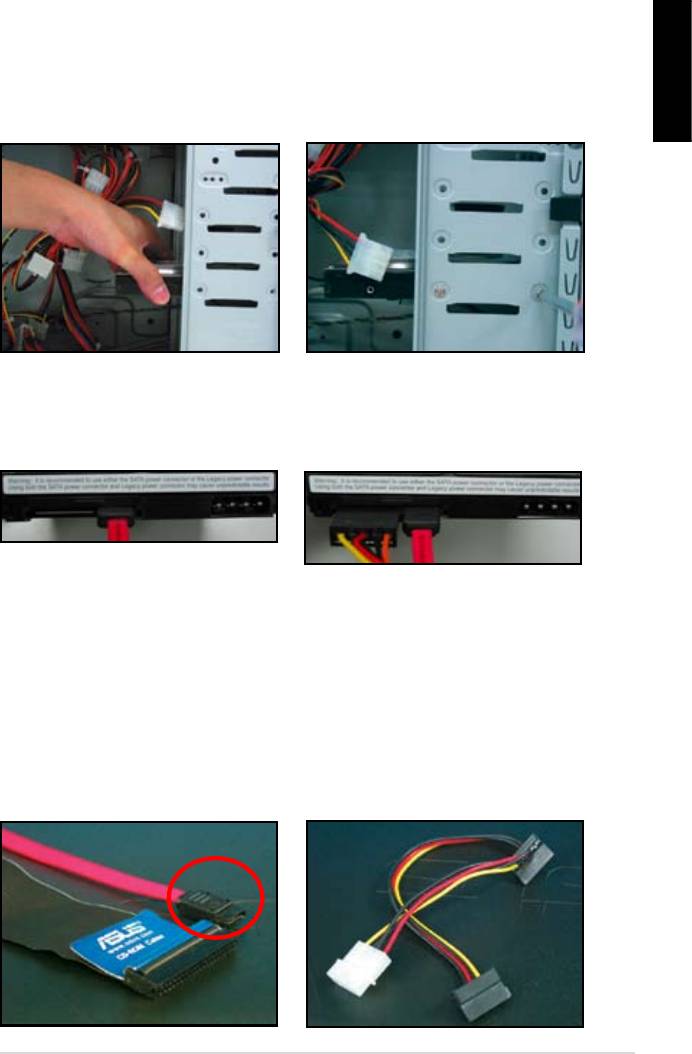
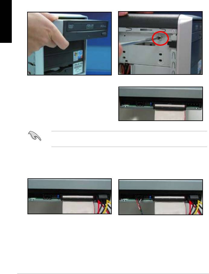
1.7.1 PATA optical disk drive
2. Align with the screw holes and
slide the optical disk drive into the
secure the disk drive with screws.
the optical drive. The red stripe on
should match the dimple marking
Pin1 on the optical drive.
4. Connect the 4‑pin power cable to
5. Attach the audio cable to the
the optical drive.
connector on the optical drive.
14
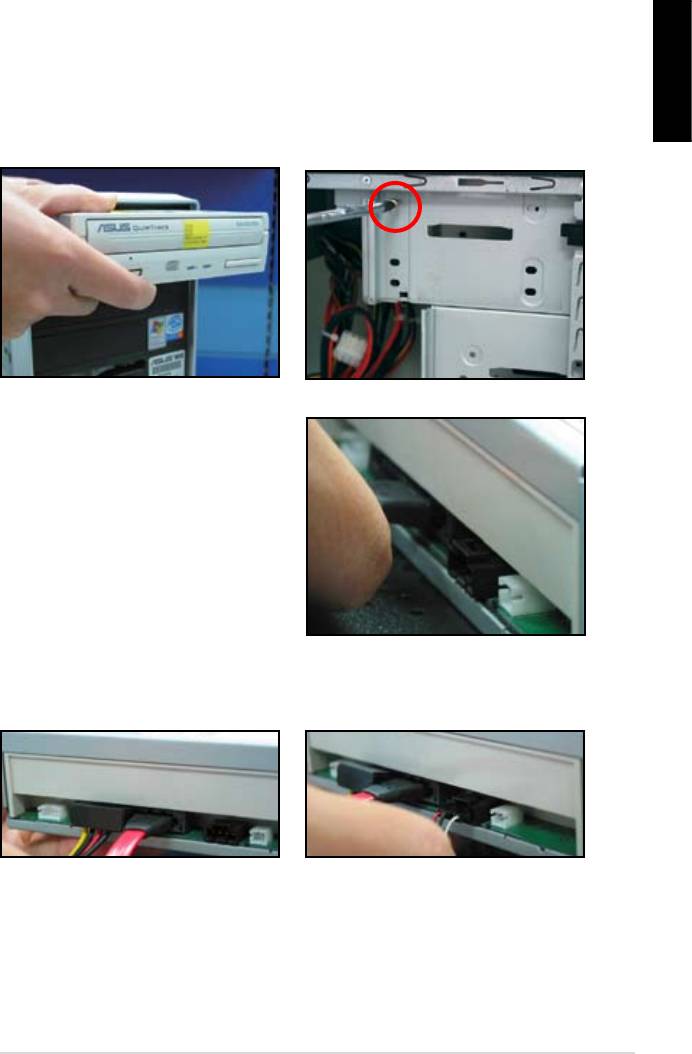
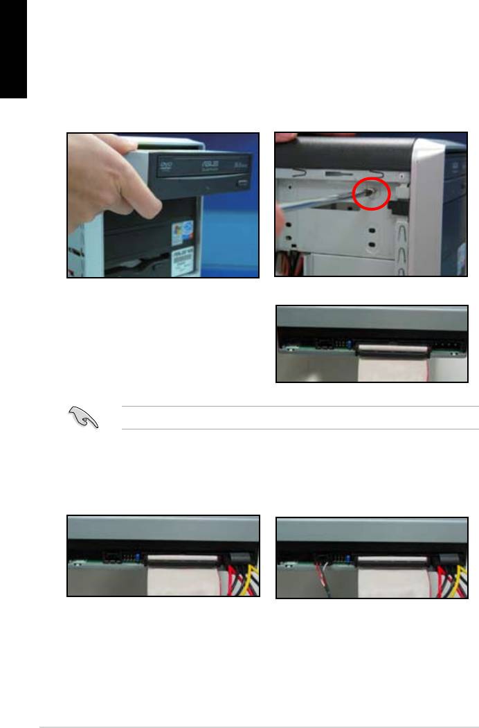
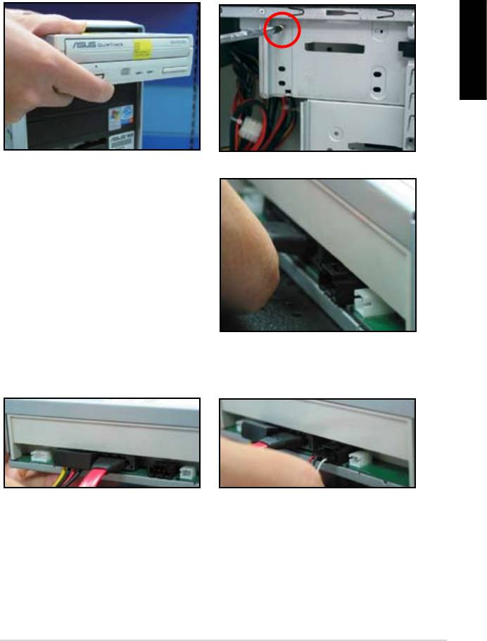
1.7.2 SATA optical disk drive
2. Align with the screw holes and
English
slide the optical disk drive into the
secure the disk drive with screws.
3. Orient and plug the SATA cable into
the optical drive. SATA cables are
cable into the connector.
4. Connect the SATA power cable to
5. Attach the audio cable to the
the the optical drive.
connector on the optical drive.
ASUS Motherboard installation guide 15
English
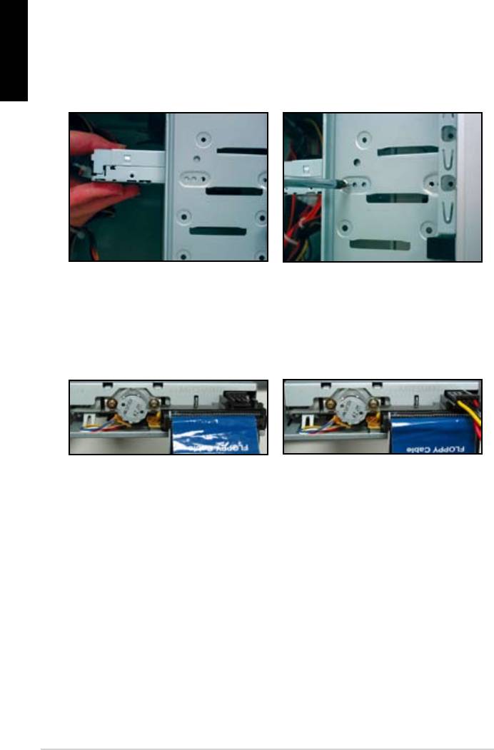
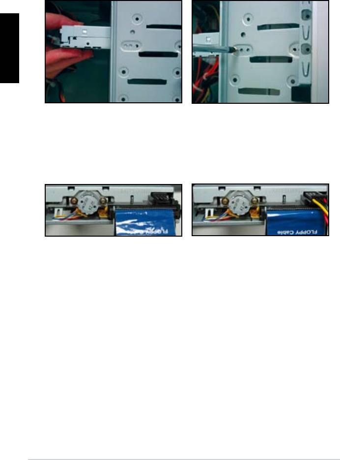
1.7.3 Floppy disk drive
2. Align with the screw holes and
secure the disk drive with screws.
the connector at the back of the
red stripe on the cable is the pin1
end and should match pin1 on the
16
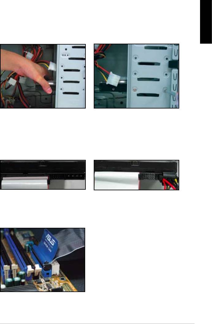
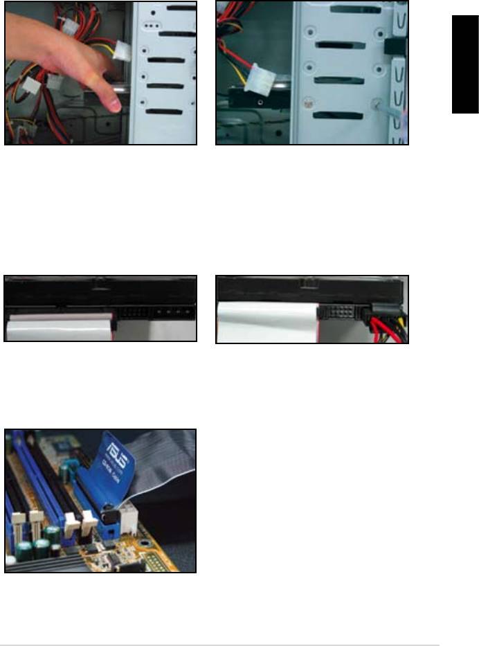
1.7.4 PATA hard disk drive
1. Insert the PATA hard disk drive into
2. Align with the screw holes and
English
secure the disk drive with screws.
3. Orient and connect the signal cable
4. Connect the 4‑pin power cable to
to the hard disk drive. The red stripe
the connector at the back of the
on the cable is the pin1 end. Match
hard disk drive.
force the cable into the connector.
5. Attach the other end of the signal
cable to the corresponding slot on
the motherboard.
ASUS Motherboard installation guide 17
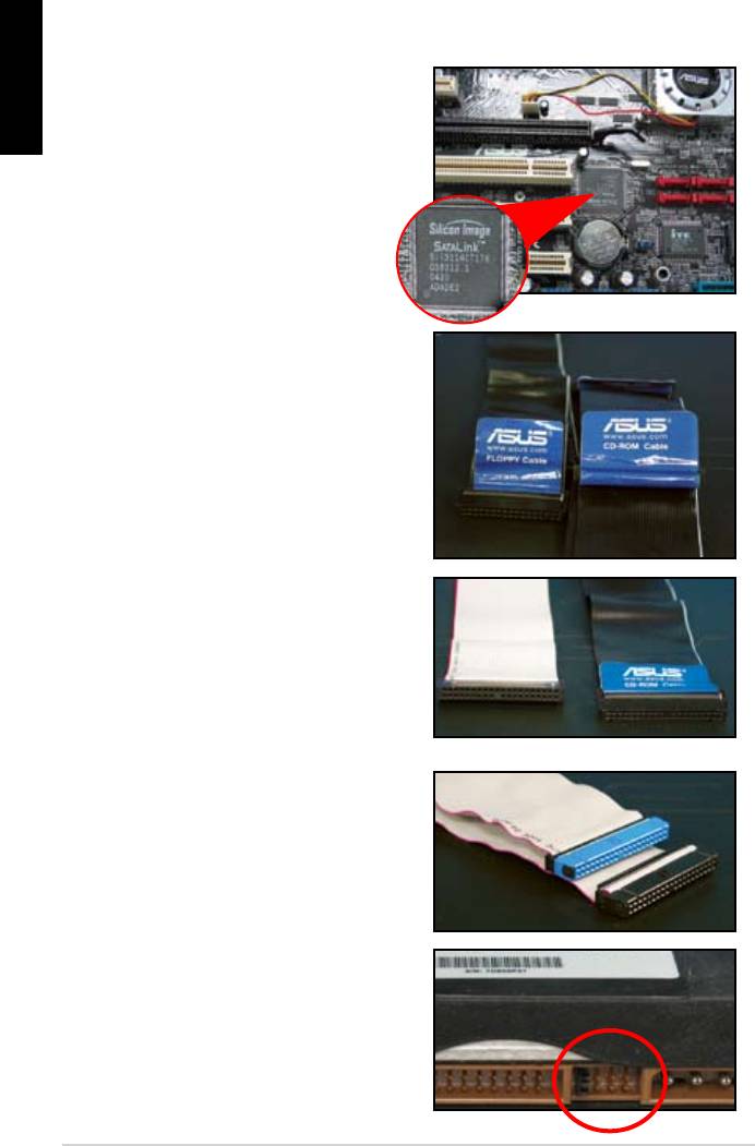
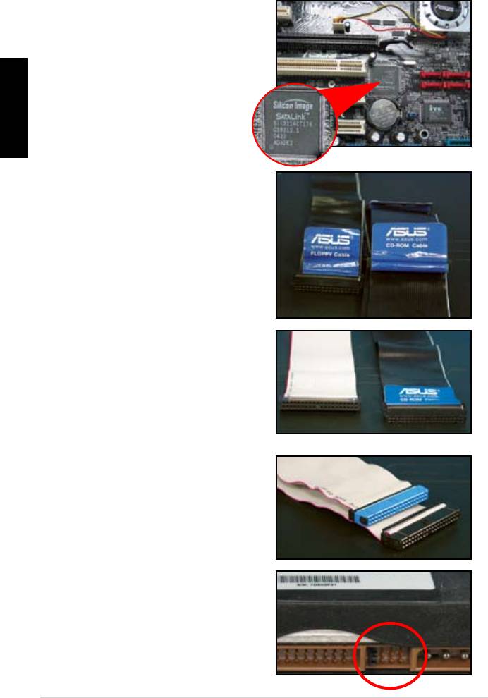
Notes for installing PATA hard disk drive
English
have to install the controller driver
• The cables are designed with pull
drives based on the cable labels.
To prevent damaging the pins, pull
the cable tabs to disconnect the
cable.
disk drives, the newer 80‑wire
(right) and the older 40‑wire (left)
cables. For ATA66/100/133 disk
offer a better performance. The
optical drives.
• The cable connector is color‑
coded. The blue one is for the host
drive.
different position, one in master
18
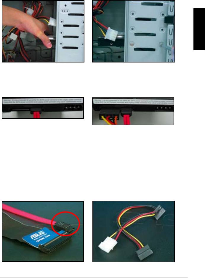
1.7.5 SATA hard disk drive
1. Insert the SATA hard disk drive into
2. Align with the screw holes and
English
secure the disk drive with screws.
3. Orient and connect the SATA cable
4. Connect the SATA power cable to
to the hard disk drive. The cable can
the connector at the back of the
hard disk drive.
Notes for installing SATA hard disk drive
• Serial ATA (SATA) interface
• The SATA power cable connector
provides higher data transmission
is different from the traditional
speed, and better voltage tolerance.
4‑pin power connector. ASUS
The narrow design of the SATA
motherboard bundles power adapter
cable also solves cabling issues
chassis.
new connector.
ASUS Motherboard installation guide 19
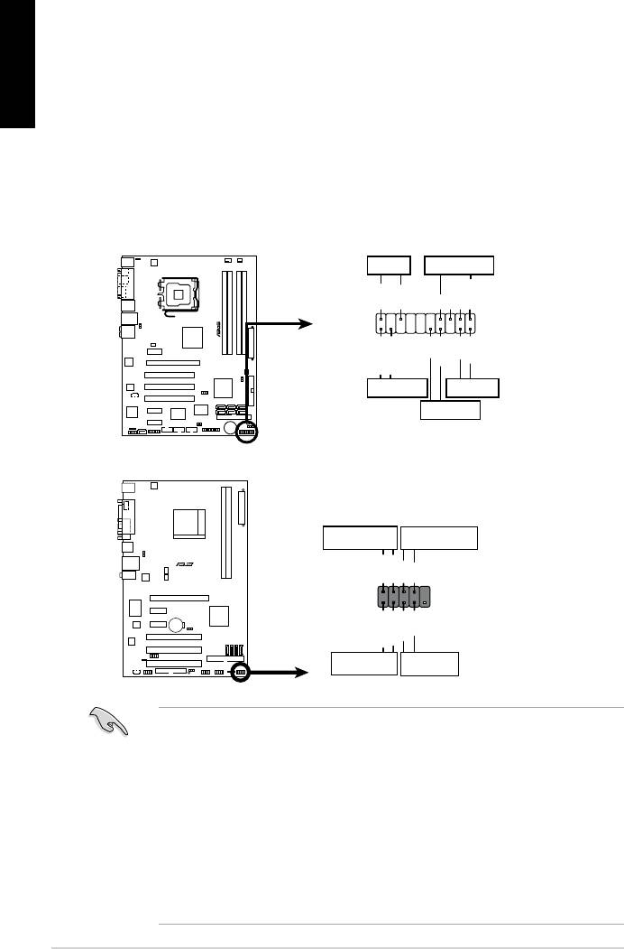
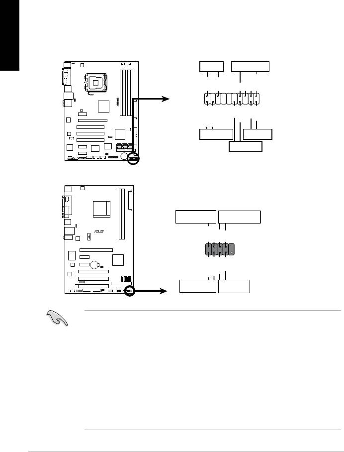
1.8 Front panel cables
English
• RESET (Reset Switch)
• SPEAKER (Speaker Connector)
20
M2N-X
Reset
ANE
RESET
PLED SPEAKER
P5B-E
PLED+
PLED-
+5V
Ground
Ground
Speaker
®
PANEL
PWR
Reset
Ground
Ground
IDE_LED+
IDE_LED-
IDE_LED
RESET
PWRSW
*
Requires an ATX power supply.
20-8 pin front panel connector
PIN1
PIN1
10-1 pin front panel connector
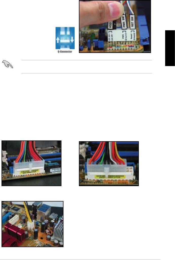
Connect these connectors to the motherboard according to the label.
for the ground pins and the color‑coded wire for the signal pins.
to the connector PIN1 on the motherboard.
user guide for more information.
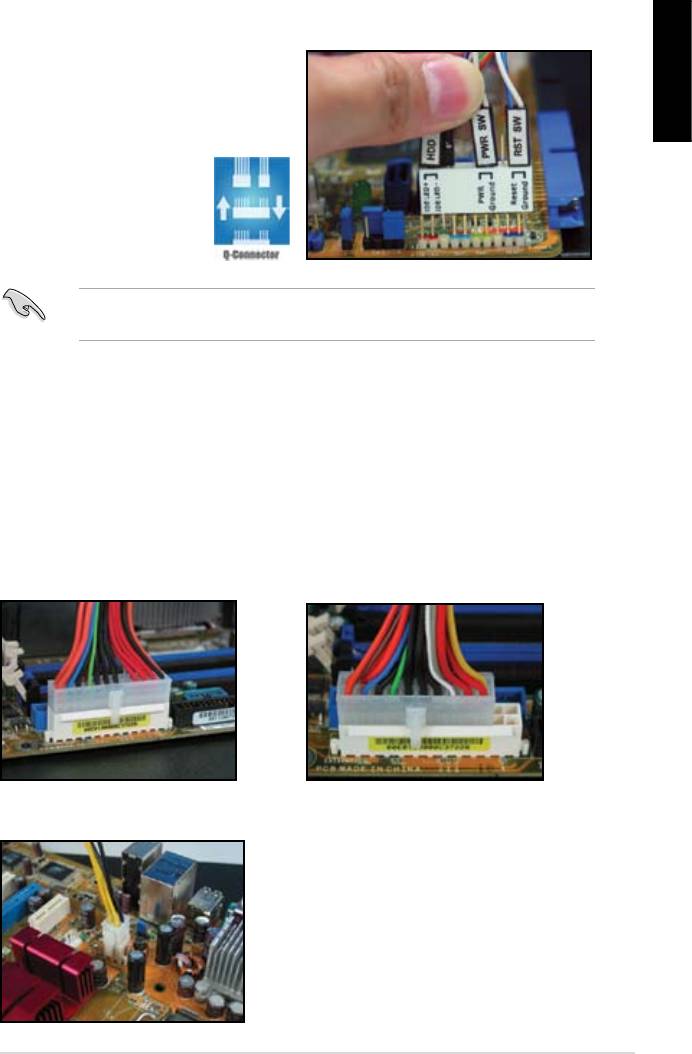
ASUS Q-Connector
English
user guide for details.
details.
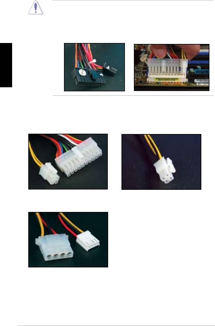
1.9 Connecting the ATX power
connector on the motherboard.
20-pin power connector
24-pin power connector
(on the 24-pin female counterpart)
4-pin power connector
ASUS Motherboard installation guide 21
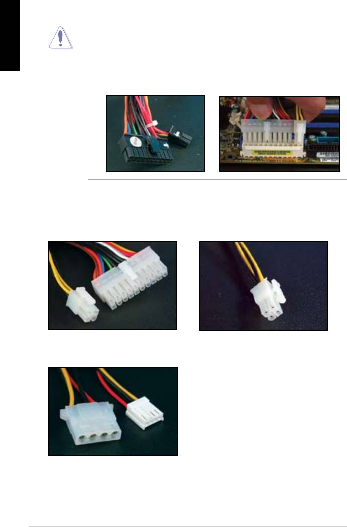
English
connectors to the motherboard.
two connectors and install to the 24‑pin connectors on the motherboard.
Power connectors
20+4 (24) pin ATX connector
4-pin ATX connector
peripheral power connector (left)
oppy power connector (right)
22
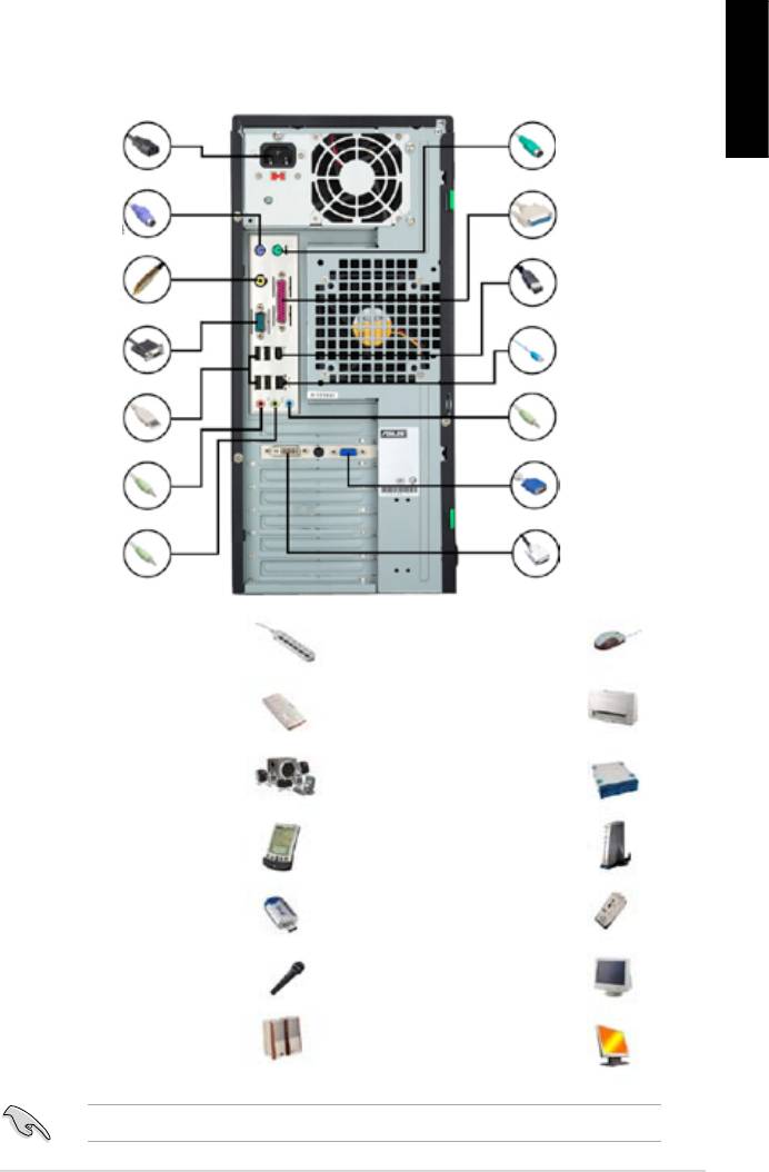
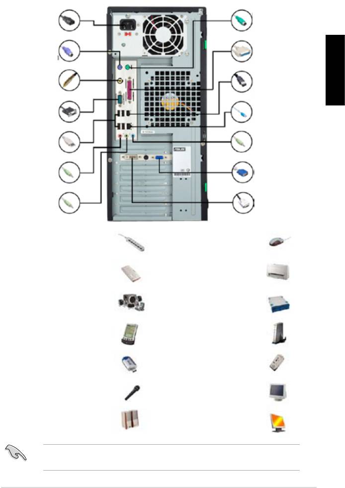
1.10 Peripheral devices and accessories
English
1. AC power plug
8. PS/2
mouse port
2. PS/2 keyboard
9. Parallel port
port
3. S/PDIF out port
10. IEEE1394 port
4. Serial port
11. LAN (RJ45) port
5. USB port
12. Line in port
13. Video graphics
6. Microphone port
adapter port
7. Line out port 14. DVI port
extension cord
mouse
hard disk drive
microphone
ASUS Motherboard installation guide 23
1.11 Startingupforthersttime
English
the BIOS beeps.
BIOS Beep Description
short beeps
short beeps then a pause (repeated)
short beeps
(AMI BIOS)
Four short beeps
Troubleshooting
Trouble Action
• Cannot turn on the computer
working.
The computer is on but the
monitor is black.
• Shut down the computer and remove the power cord.
socket.
a warning message pops on
the screen.)
drive.
• Make sure the device drivers are installed.
24

Chapter 2: Manage/update BIOS
2.1 AFUDOS utility
English
corrupted during the updating process.
Copying the current BIOS
afudos /o[lename]
characters for the extension name.
A:>afudos /oOLDBIOS1.rom
Main lename Extension name
A:>afudos /oOLDBIOS1.rom
AMI Firmware Update Utility — Version 1.19(ASUS V2.07(03.11.24BB))
Copyright (C) 2002 American Megatrends, Inc. All rights reserved.
Reading ash ….. done
Write to le…… ok
A:>
Updating the BIOS le
ASUS Motherboard installation guide 25

English
afudos /i[lename]
disk.
A:>afudos /iP5K3D.ROM
A:>afudos /iP5K3D.ROM
AMI Firmware Update Utility — Version 1.19(ASUS V2.07(03.11.24BB))
Copyright (C) 2002 American Megatrends, Inc. All rights reserved.
WARNING!! Do not turn off power during ash BIOS
Reading le ……. done
Reading ash …… done
Advance Check ……
Erasing ash …… done
Writing ash …… 0x0008CC00 (9%)
A:>afudos /iP5K3D.ROM
AMI Firmware Update Utility — Version 1.19(ASUS V2.07(03.11.24BB))
Copyright (C) 2002 American Megatrends, Inc. All rights reserved.
WARNING!! Do not turn off power during ash BIOS
Reading le ……. done
Reading ash …… done
Advance Check ……
Erasing ash …… done
Writing ash …… done
Verifying ash …. done
Please restart your computer
A:>
26 Manage/update BIOS
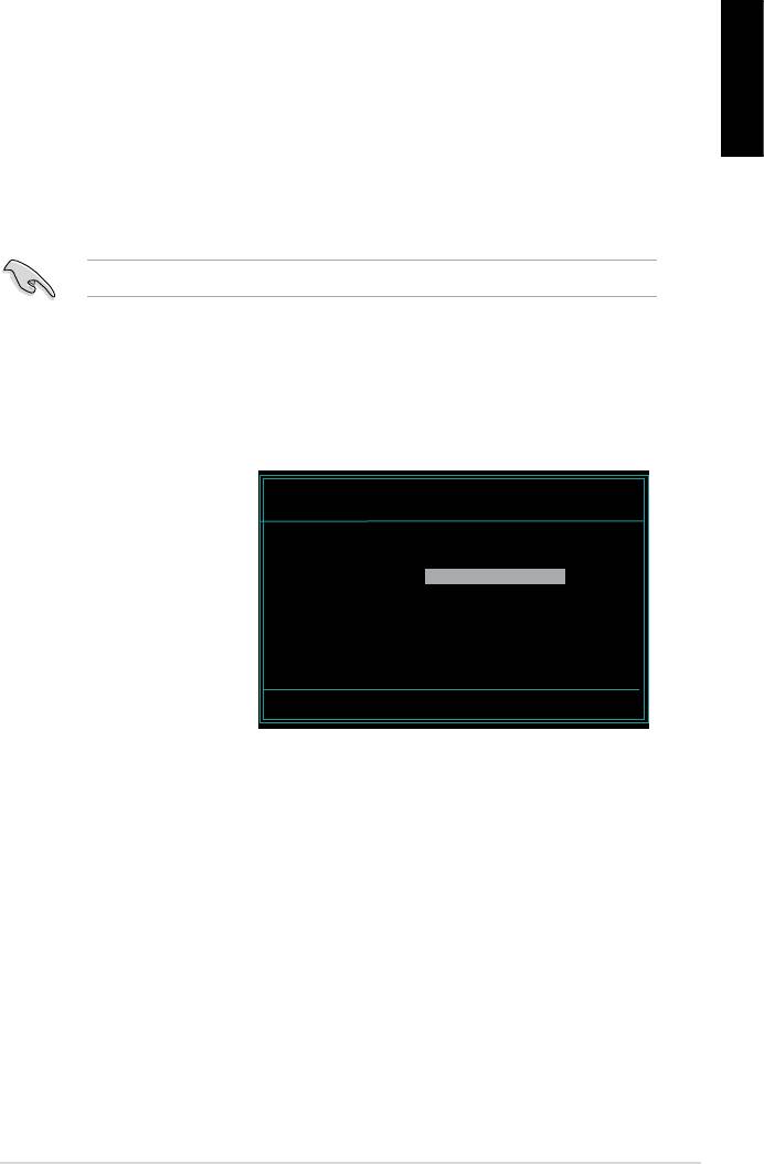
2.2 Award BIOS Flash Utility
Updating the BIOS
English
FAT 16/12 format.
AwardBIOS Flash Utility for ASUS V1.14
(C) Phoenix Technologies Ltd. All Rights Reserved
the name of the disk
For NF590-SLI-M2N32-SLI-DELUXE DATE:03/30/2006
Flash Type — PMC Pm49FL004T LPC/FWH
assignment) to switch to
File Name to Program:
Message: Please input File Name!
<Enter>. The Award BIOS
ASUS Motherboard installation guide 27
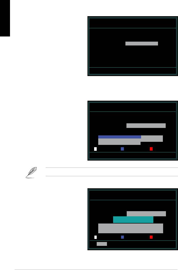
English
AwardBIOS Flash Utility for ASUS V1.14
the File Name to Program
(C) Phoenix Technologies Ltd. All Rights Reserved
For NF590-SLI-M2N32-SLI-DELUXE DATE:03/30/2006
Flash Type — PMC Pm49FL004T LPC/FWH
File Name to Program: M2N32SLI.bin
Message: Do You Want To Save Bios (Y/N)
following screen appears.
AwardBIOS Flash Utility for ASUS V1.14
(C) Phoenix Technologies Ltd. All Rights Reserved
For NF590-SLI-M2N32-SLI-DELUXE DATE:03/30/2006
Flash Type — PMC Pm49FL004T LPC/FWH
File Name to Program: M2N32SLI.bin
Programming Flash Memory — OFE00 OK
Write OK No Update Write Fail
Warning: Don’t Turn Off Power Or Reset System!
AwardBIOS Flash Utility for ASUS V1.14
Flashing Complete
(C) Phoenix Technologies Ltd. All Rights Reserved
message indicating that
For NF590-SLI-M2N32-SLI-DELUXE DATE:03/30/2006
Flash Type — PMC Pm49FL004T LPC/FWH
File Name to Program: M2N32SLI.bin
Flashing Complete
Remove the disk then
Press <F1> to Continue
press <F1> to restart the
Write OK No Update Write Fail
F1
Reset
28 Manage/update BIOS
Saving the current BIOS le
English
process.
1. Follow steps 1 to 6 of the
AwardBIOS Flash Utility for ASUS V1.14
(C) Phoenix Technologies Ltd. All Rights Reserved
previous section.
For NF590-SLI-M2N32-SLI-DELUXE DATE:03/30/2006
Flash Type — PMC Pm49FL004T LPC/FWH
File Name to Program: 0112.bin
following screen appears.
Save current BIOS as:
Message:
AwardBIOS Flash Utility for ASUS V1.14
(C) Phoenix Technologies Ltd. All Rights Reserved
For NF590-SLI-M2N32-SLI-DELUXE DATE:03/30/2006
Flash Type — PMC Pm49FL004T LPC/FWH
then press <Enter>.
File Name to Program: 0112.bin
Checksum: 810DH
Save current BIOS as: 0113.bin
Message: Please Wait!
AwardBIOS Flash Utility for ASUS V1.14
(C) Phoenix Technologies Ltd. All Rights Reserved
disk, then returns to the
For NF590-SLI-M2N32-SLI-DELUXE DATE:03/30/2006
Flash Type — PMC Pm49FL004T LPC/FWH
File Name to Program: 0113.bin
Now Backup System BIOS to
File!
Message: Please Wait!
ASUS Motherboard installation guide 29

2.3 ASUS Update utility
English
®
package.
ASUS Update requires an Internet connection either through a network or an
Internet Service Provider (ISP).
Installing ASUS Update
30 Manage/update BIOS
®
English
Updating the BIOS through the Internet
®
desktop, click Start >
Programs > ASUS > ASUSUpdate > ASUSUpdate. The ASUS Update main
window appears.
2. Select Update BIOS from the
3. Select the ASUS FTP site nearest
drop‑down menu list, then click
Next.
click Auto Select. Click Next.
ASUS Motherboard installation guide 31
English
4. From the FTP site, select the BIOS
Click Next.
5. Follow the screen instructions to
complete the update process.
capable of updating itself through
Updating the BIOS through a BIOS le
®
desktop, click Start
> Programs > ASUS > ASUSUpdate > ASUSUpdate. The ASUS Update
main window appears.
2. Select
Update BIOS from the
drop‑down menu list, then click Next.
window, then click Open.
P5K3 Deluxe
4. Follow the screen instructions to
complete the update process.
P5K3 Deluxe
32 Manage/update BIOS
Chapter 3: Troubleshooting
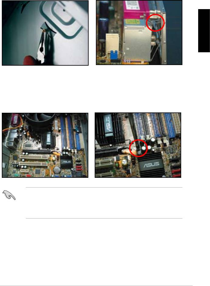
3.1 Troubleshooting for Motherboard DIY
English
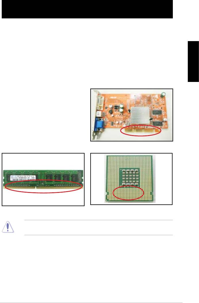
3.1.1 Basic troubleshooting
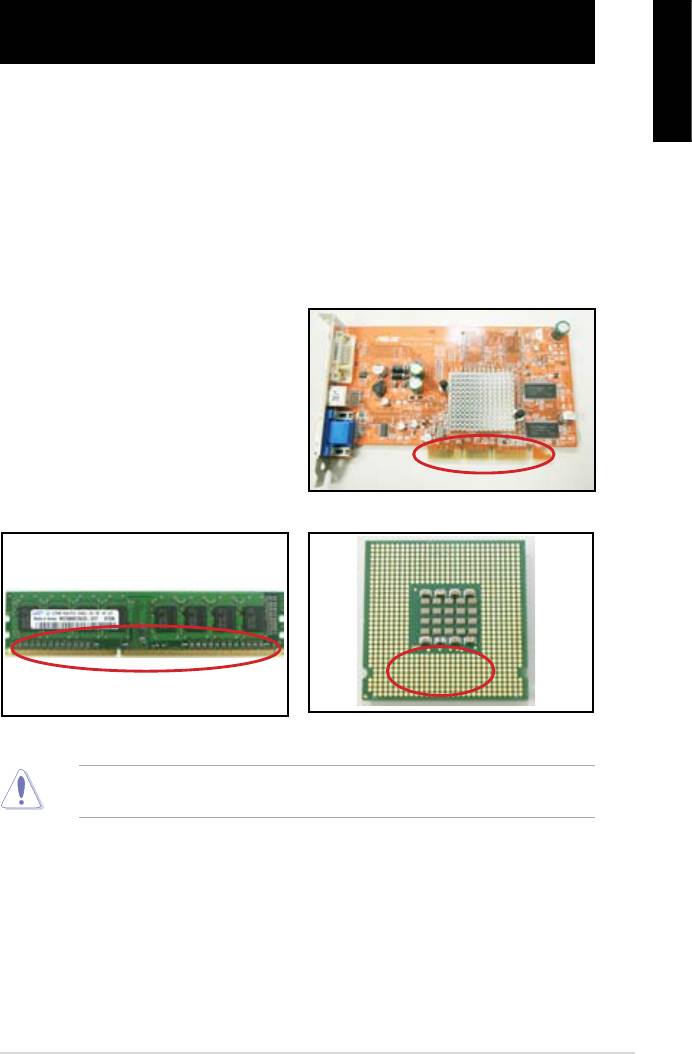
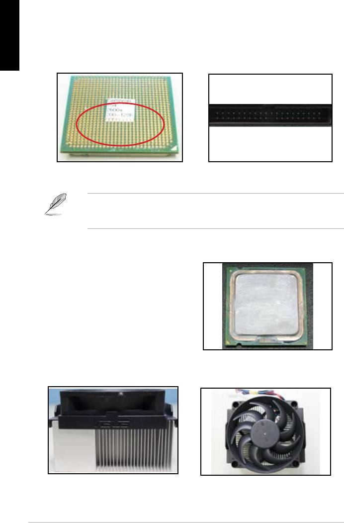
A. Bad connection
1. Make sure there is no contaminants
on the gold contact or the pins.
2. Use a cotton bud or an eraser
crumbs.
VGA card gold contact
DIMM gold contact
LGA775 processor gold contact points
ASUS Motherboard installation guide 33
English
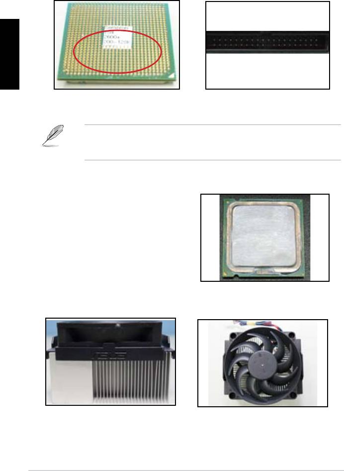
CPU pins. A broken and bended pin will cause the component malfunction.
AMD CPU gold pins
Connector pins
B. CPU overheated
thermal paste to the exposed area
of the CPU that the heatsink will be
in contact with. Make sure that it is
CPU surface
2. Make sure there is no contaminants on the heatsink and fan.
Side view of heatsink and fan
Top view of heatsink and fan
3. Follow the instructions of heatsink and fan manufacturers to clean the
contaminants that will slow down the fan rotation.
34 Troubleshooting
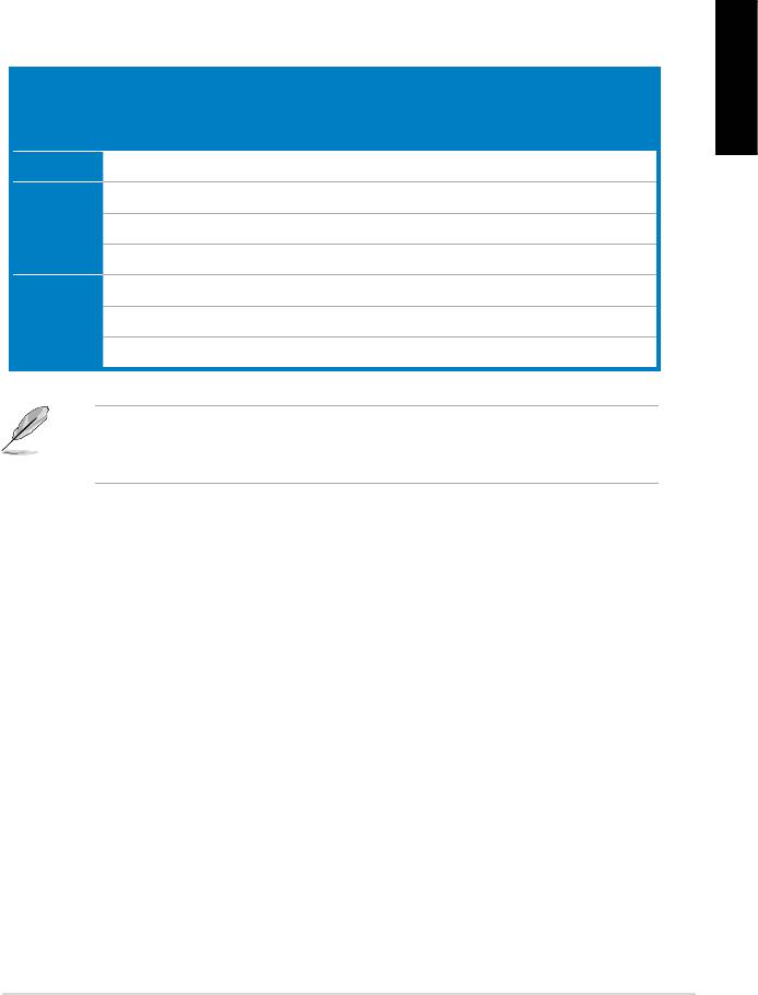
3.2 Other common troubles
unplugged.
English
Test (POST).
• If there are BIOS beeps, refer to section 1.11 for details.
Check Items
Power
Screen
Heatsink
BIOS
Error
Reference
LED
display
and fan
beeps
messages
page
No power Off No Stop No N/A 3‑4
No
On No Stop No N/A 3‑5
screen
On No Running No N/A 3‑5
display
On No Running N//A 3‑5
Failure to
On Running 3‑5
enter OS
On Running No 3‑5
On Running No No 3‑5
team for further help.
ASUS Motherboard installation guide 35
English
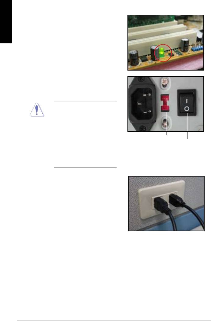
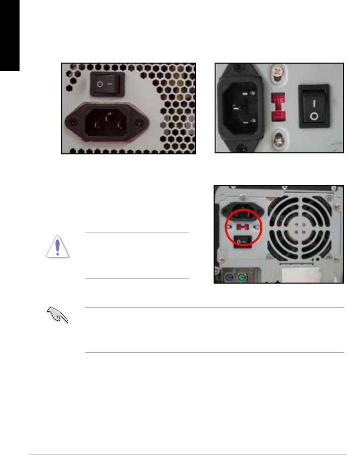
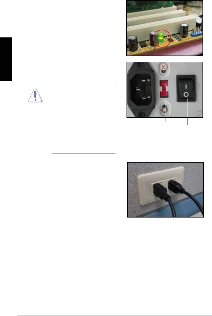
3.2.1 No power
the problem.
input voltage, ensure to
disconnect the power
plug. Failure to do so will
AC input voltage switch
Power switch
“—”: On; “O”: Off
power cord to the wall outlet.
• Connect the power plug
NOT connect it to the power
extension, uninterruptible
devices.
• Exchange the power plugs of
check whether the wall outlet is
36 Troubleshooting

3.2.2 Failure to boot-up; No screen display
English
the monitor.
2. Make sure if the problem comes from expansion devices.
3.2.3 Failure to enter the operating system
Contact the device retailer for help.
driver.
the BIOS to load the setup defaults. Refer the motherboard user guide for
details.
ASUS Motherboard installation guide 37

English
using an anti‑virus application.
3.2.4 FAQs
normal.
disk drives.
38 Troubleshooting

Chapter 4: Computer care tips
4.1 Proper care of your PC
English
the computer when it is turned on in case of damage. Internal dust will affect
the operating disk drive and contribute to overheating problem which will cause
computer crash or damage the components.
4.2 Basic knowledge
the ventilation holes. Excessive heat will cause the monitor malfunction.
4. Place the computer on a stable surface.
the best surroundings temperature. Use an air conditioner or a electric fan to
gain a better heat dissipation.
4.3 Usage knowledge
recommended.
cleaning)
• Uninstall the motherboad and hard/optical disk drives, then clean them
with canned air or a soft brush.
static vacuum.
ASUS Motherboard installation guide 39

English
4.4 Tips
40 Computer care tip

Anakart
kurulumkılavuzu
Motherboard

TR4204
Nisan 2008
Telif Hakkı © 2008 ASUSTeK COMPUTER INC. Tüm hakları saklıdır.
Türkçe
Bu el kitabının hiçbir bölümü, onun içinde tanımlanan yazılım ve de ürünler
de dahil olmak üzere, ASUSTeK COMPUTER INC. (“ASUS”) rmasının
açık bir biçimde yazılı izni olmaksızın, satın alan kişi tarafından yedek—
leme amaçlı olarak tutulan dokümantasyon haricinde yeniden üretilemez,
aktarılamaz, kopya edilemez, bir bilgi işlem sistemi içinde depolanamaz, ya
da her hangi bir şekilde ya da hiçbir biçimde hiçbir dile tercüme edilemez.
Aş
ğ
ıdaki şartlarda ürün garantisi ya da hizmeti uzatılmayacaktır: (1) ürünün
ASUS tarafından yazılı bir izin olmaksızın onarılması veya de
ği
ştirilmesi ya
da (2) ürünün seri numarasının tahrif edilmesi ve kaybolmas.
ASUS BU EL KİTABINI, BELİRLİ BİR AMAÇ İÇİN TİCARETE
ELVERİŞLİ NİTELİĞİN YA UYGUNLUĞUN ZIMNİ GARANTİLER
YA DA KOŞULLARI DA DAHİL OLMAK ÜZERE YA DA BUNLARLA
SINIRLI OLMAMAK KAYDIYLAYA AÇIK BİR ŞEKİLDE YA DA ZIM—
NEN HER HANGİ BİR TÜRÜN GARANTİSİ OLMAKSIZIN “OLDUĞU
GİBİ” SAĞLAR. HİÇBİR DURUMDA ASUS, ONUN DİREKTÖRLERİ,
MEMURLARI, ÇALIŞANLARI YA DA ACENTELERİ, BU EL KİTABI
YA DA ÜRÜN İÇERİSNDE HER HANGİ BİR KUSUR YA DA HATADAN
DOĞAN BU TÜR ZARARLARIN MEYDANA GELME OLASILIĞINI
TAVSİYE ETMİŞ OLSA DAHİ, HER HANGİ BİR DOLAYLI, ÖZEL,
TESADÜFİ YA DA SONUÇSAL ZARARLARDAN ( KAR KAYIPLA—
RI, İŞ KAYBI, KULLANIM YA DA VERİ KAYBI, İŞİN KESİNTİYE
UĞRAMASI VE DE BENZERİ GİBİ ZARARLAR DA DAHİL OLMAK
ÜZERE ) ÖTÜRÜ SORUMLU TUTULAMAZ.
BU EL KİTABI İÇİNDE YER ALAN SPESİFİKASYONLAR
VE DE BİLGİ SADECE BİLGİLENDİRME AMAÇLI OLARAK
TEDARİK EDİLMİŞTİR VE DE HER HANGİ BİR BİLDİRİMDE
B U L KUN U L MA K S IN I N H E R H A N Gİ B İR Z AM A N D A
DEĞİŞTİRİLMEYE TABİİDİR, VE DE ASUS TARAFINDAN BİR TAAH—
HÜT ŞEKLİNDE YOURMLANAMAZ. ASUS BU EL KİTABINDA VE
DE ONUN İÇİNDE TANIMLANAN YAZILIM VE DE ÜRÜNLERDE DE
DAHİL OLMAK ÜZERE GÖRÜNEN HER HANGİ BİR HATA YA DA
KUSURLARDAN ÖTÜRÜ HİÇBİR YÜKÜMLÜLÜK YA DA SORUM—
LULUK ÜSTLENMEZ.
Bu el kitabı içinde görünen ürünler ve de kurum isimleri, onların şirketlerinin
tescilli ticari markaları ya da telif hakları olabilir ya da olmayabilir ve de
ihlal amaçlı olmaksızın sadece tanıtım ya da açıklama amaçlı olarak ve de
mal sahibinin yararına kullanılmaktadır.
42

Güvenlik bilgileri
Elektriksel güvenlik
Türkçe
Çalıştırma güvenliği
43
Bölüm 1: Hızlı Çalıştırma
1.1 CPU Montajı
1.1.1 Intel LGA775 Soket
Türkçe
tespit edin.
Soket pinlerine hasar gelmesini
önlemek için CPU kurulumu
Kaldır-Yerleştir Başlığı (PnP Başlığı)
44
Türkçe
itin.
konektörlerin bükülmesini ve
CPU’nun hasar görmesini
1.1.2 Intel LGA1366 Yuvası
Tutma çıkıntısı
A
B
sola (B) hareket ettirin.
Yük kolu
önlemek için, bir CPU takana
Yük levhası
4
3
45
Türkçe
Altın
Üçgen
işareti
PnP kapağı
CPU çentiği
Hizalama anahtarı
A
oturana kadar ittirin.
B
46
1.1.3 AMD AM2 Yuvası
Türkçe
oturur.
47
1.2 Isı emici ve fan montajı
Türkçe
Intel sertikalı ısı emici için:
macunla birlikte gelir. Bu durumda
48
B
A
A
B
Türkçe
AMD sertikalı ısı emici için:
1
2
3
4
49
1.3 DIMM Montajı
2
Türkçe
DDR2 DIMM çentiği
3
1
1
Kilidi açık tutturucu klipsi
müracaat edin.
1.4 Anakart montajı
paketi ile birlikte gelen arka I/O
50
edin.
dikkatli olun.
Türkçe
51
1.5 Güç kaynağı ünitesi montajı
Aktif PFC’li güç kaynağı:
Pasif PFC’li güç kaynağı:
Türkçe
verir.
müracaat edin.
52
1.6 Genişletme kartı montajı
Türkçe
PCI kartı PCIE x16 kartı
PCIE x1 kartı
53
1.7 Disk sürücülerinin montajı
1.7.1 PATA optik disk sürücüsü
disk sürücüsünü vidalarla
Türkçe
pin1 ucudur ve optik sürücüdeki
gelmelidir.
4. 4 pinli güç kablosunu optik
5. Ses kablosunu optik sürücüdeki
54
1.7.2 SATA optik disk sürücüsü
disk sürücüsünü vidalarla
Türkçe
5. Ses kablosunu optik sürücüdeki
55
1.7.3 Disket sürücü
Türkçe
56
1.7.4 PATA sabit disk sürücü
Türkçe
4. 4 pinli güç kablosunu sabit disk
57
PATA sabit disk sürücü montajı ile ilgili notlar
Türkçe
• Kablolar çekme uçlu olarak
sadece kablo etiketlerine göre
Pinlere hasar gelmesini önlemek
çekerek kesin.
ATA66/100/133 disk sürücüler
için sadece 80‑telli kablo daha
kablolar genellikle optik sürücüler
içindir.
• Kablo konnektörü renk kodludur.
Mavi olan ana konnektördür,
sürücü içindir.
58
1.7.5 SATA sabit disk sürücü
Türkçe
4. SATA güç kablosunu sabit disk
oturabilir.
SATA sabit disk sürücü montajı ile ilgili notlar
• SATA güç kablosu konnektörü
geleneksel 4 pinli güç
kablolama ile ilgili meselelere
konnektörü içermemesi durumunda
59
1.8 Ön panel kabloları
Türkçe
60
M2N-X
Reset
ANE
RESET
PLED SPEAKER
P5B-E
PLED+
PLED-
+5V
Ground
Ground
Speaker
®
PANEL
PWR
Reset
Ground
Ground
IDE_LED+
IDE_LED-
IDE_LED
RESET
PWRSW
*
Requires an ATX power supply.
20-8 pinli ön panel konnektörü
PIN1
PIN1
10-1 pinli ön panel konnektörü
ASUS Q-Konnektör
müracaat edin.
Türkçe
1.9 ATX gücünün bağlanması
20 pinli güç konnektörü
24 pinli güç konnektörü
(24 pinli dişi karşılığında)
4 pinli güç konnektörü
61
Türkçe
Güç konnektörleri
20+4 (24) pin ATX konnektör
4 pinli ATX konnektör
çevre birim güç konnektörü (sol)
disket güç konektörü (sağ)
62
1.10 Çevre birimleri ve aksesuarlar
1. AC güç şi
8. PS/2 fare
portu
2. PS/2 klavye
9. Paralel port
portu
3. S/PDIF çıkış
10. IEEE1394 portu
Türkçe
portu
4. Seri port
11. LAN (RJ45)
portu
5. USB portu
12. Hat giriş
portu
13. Video grak
6. Mikrofon portu
adaptör portu
7. Hat çıkış portu 14. DVI portu
kablosu
5.1 hoparlör sistemi
sabit disk sürücü
63

1.11 İlk kez çalıştırma
BIOS Bip Sesi Açıklama
sesi
Türkçe
bip sesi
(AMI BIOS)
Sorun Giderme
Sorun Eylem
emin olun.
Slave)
kontrol edin.
64

Bölüm 2: BIOS Yönetme/güncelleme
2.1 AFUDOSprogramı
Mevcut BIOS’un Kopyalanması
Türkçe
afudos /o[dosya adı]
A:>afudos /oOLDBIOS1.rom
Ana dosya adı Uzatma adı
A:>afudos /oOLDBIOS1.rom
AMI Firmware Update Utility — Version 1.19(ASUS V2.07(03.11.24BB))
Copyright (C) 2002 American Megatrends, Inc. All rights reserved.
Reading ash ….. done
Write to le…… ok
A:>
BIOS dosyasının güncellenmesi
65
afudos /i[dosya adı]
Türkçe
A:>afudos /iP5K3D.ROM
A:>afudos /iP5K3D.ROM
AMI Firmware Update Utility — Version 1.19(ASUS V2.07(03.11.24BB))
Copyright (C) 2002 American Megatrends, Inc. All rights reserved.
WARNING!! Do not turn off power during ash BIOS
Reading le ……. done
Reading ash …… done
Advance Check ……
Erasing ash …… done
Writing ash …… 0x0008CC00 (9%)
A:>afudos /iP5K3D.ROM
AMI Firmware Update Utility — Version 1.19(ASUS V2.07(03.11.24BB))
Copyright (C) 2002 American Megatrends, Inc. All rights reserved.
WARNING!! Do not turn off power during ash BIOS
Reading le ……. done
Reading ash …… done
Advance Check ……
Erasing ash …… done
Writing ash …… done
Verifying ash …. done
Please restart your computer
A:>
66
2.2 Award BIOS Flash Programı
BIOS güncelleme
FAT 16/12 biçimindeki
Türkçe
AwardBIOS Flash Utility for ASUS V1.14
(C) Phoenix Technologies Ltd. All Rights Reserved
gösterir) kullanarak
For NF590-SLI-M2N32-SLI-DELUXE DATE:03/30/2006
Flash Type — PMC Pm49FL004T LPC/FWH
File Name to Program:
diskinin ve Award BIOS
klasörüne geçin.
Message: Please input File Name!
67
AwardBIOS Flash Utility for ASUS V1.14
(C) Phoenix Technologies Ltd. All Rights Reserved
For NF590-SLI-M2N32-SLI-DELUXE DATE:03/30/2006
Flash Type — PMC Pm49FL004T LPC/FWH
File Name to Program: M2N32SLI.bin
Türkçe
Message: Do You Want To Save Bios (Y/N)
AwardBIOS Flash Utility for ASUS V1.14
(C) Phoenix Technologies Ltd. All Rights Reserved
For NF590-SLI-M2N32-SLI-DELUXE DATE:03/30/2006
Flash Type — PMC Pm49FL004T LPC/FWH
File Name to Program: M2N32SLI.bin
Programming Flash Memory — OFE00 OK
Write OK No Update Write Fail
Warning: Don’t Turn Off Power Or Reset System!
AwardBIOS Flash Utility for ASUS V1.14
(C) Phoenix Technologies Ltd. All Rights Reserved
For NF590-SLI-M2N32-SLI-DELUXE DATE:03/30/2006
Flash Type — PMC Pm49FL004T LPC/FWH
File Name to Program: M2N32SLI.bin
Flashing Complete
Press <F1> to Continue
Write OK No Update Write Fail
F1
Reset
68
Mevcut BIOS dosyasının kaydedilmesi
1. Önceki ekrandaki 1.
AwardBIOS Flash Utility for ASUS V1.14
Türkçe
(C) Phoenix Technologies Ltd. All Rights Reserved
For NF590-SLI-M2N32-SLI-DELUXE DATE:03/30/2006
Flash Type — PMC Pm49FL004T LPC/FWH
2. Program mevcut BIOS
File Name to Program: 0112.bin
Save current BIOS as:
belirir.
Message:
AwardBIOS Flash Utility for ASUS V1.14
(C) Phoenix Technologies Ltd. All Rights Reserved
For NF590-SLI-M2N32-SLI-DELUXE DATE:03/30/2006
Flash Type — PMC Pm49FL004T LPC/FWH
File Name to Program: 0112.bin
Checksum: 810DH
Save current BIOS as: 0113.bin
Message: Please Wait!
4. Program mevcut BIOS
AwardBIOS Flash Utility for ASUS V1.14
(C) Phoenix Technologies Ltd. All Rights Reserved
For NF590-SLI-M2N32-SLI-DELUXE DATE:03/30/2006
Flash Type — PMC Pm49FL004T LPC/FWH
File Name to Program: 0113.bin
Now Backup System BIOS to
File!
Message: Please Wait!
69

2.3 ASUSGüncellemeprogramı
®
Türkçe
• BIOS sürüm bilgilerinin görüntülenmesi.
ASUS Güncellemesinin Kurulması
Sürücüler menüsü belirir.
2. ProgramlarASUS Güncellemesini Kur’a
70
®
BIOS’un internetten güncellenmesi
1. Başlat > Programlar > ASUS > ASUSUpdate > ASUSUpdate
®
Türkçe
BIOS’u
İnternetten Güncelle
İleri
Oto Seçİleri
71
BIOS sürümünü seçin. İleri
Türkçe
BIOS’un BIOS dosyasından güncelleme
1. Başlat > Programlar > ASUS > ASUSUpdate > ASUSUpdate
®
BIOS’u
Dosyadan Güncelle
İleri
Açık pencereden
Aç
P5K3 Deluxe
getirin.
P5K3 Deluxe
72
Bölüm 3: Sorun Giderme
3.1 Anakart DIY için Sorun Giderme
Türkçe
3.1.1 Temel sorun giderme
A. Kötü bağlantı
VGA kartı altın kontak
DIMM altın kontak
LGA775 işlemci altın kontak noktaları
73
Türkçe
AMD CPU altın pinler
Konektör pinleri
B. CPU’nun aşırı ısınması
CPU yüzeyi
Isı emici ve fan yan görünümü
Isı emici ve fan üst görünümü
74
3.2 Diğer yaygın sorunlar
emin olun.
gösterilecektir.
Kontrol öğeleri
Türkçe
Güç LED’i Ekran
Isı emici
BIOS Bip
Hata
Referans
göstergesi
ve fan
Sesleri
mesajları
sayfa
Güç yok N/A 3‑4
Ekran
N/A 3‑5
göstergesi
N/A 3‑5
yok
Evet N//A 3‑5
İşletim
Evet Evet Evet 3‑5
Sistemine
Evet Evet 3‑5
Giriş
Başarısız
Evet 3‑5
destek ekibi ile temasa geçin.
75
3.2.1 Güç yok
Türkçe
emin olun.
AC giriş voltaj düğmesi
Güç düğmesi
“—”: Açık;
“O”: Kapalı
• Sistem ve monitöre ait güç
76

3.2.2 Ön yükleme başarısız; Görüntü yok
olun.
Türkçe
olun.
3.2.3 İşletim sistemine giriş başarısız
ile temasa geçin.
gerekebilir.
77

Türkçe
gerekebilir.
3.2.4 Sıkça Sorulan Sorular
normaldir.
78

Bölüm 4: Bilgisayar bakımı ile ilgili ipuçları
4.1 Bilgisayarınızın uygun bakımı
4.2 Temel bilgiler
Türkçe
olur.
4.3 Kullanım bilgileri
4.4 İpuçları
79

Türkçe
80
- Инструкции и руководства
- Бренды
- ASUS
- P5GC-MX /1333
- Справочник Пользователя
![]()
Ваш электронный адрес не будет опубликован. Обязательные поля помечены * *
КОММЕНТАРИЙ *
Имя и фамилия
Эл. адрес
Cайт
Сохраните мое имя, адрес электронной почты и веб-сайт в этом браузере для следующего комментария.

Français
Deutsch
Italiano
Español
Русский
Português
Polski
Česky
Magyar
Български
Română
Srpski
Quick Start Guide
U3363
P5GC-MX/1333
First Edition Published August 2007
Copyright © 2007 ASUSTeK COMPUTER INC. All Rights Reserved.
15G0639040K0