Руководства пользователя
Версия D072
383.69 KB
Turbo Unlocker (TurboV EVO) Instruction
Версия G5138
8.95 MB
P7P55D-E user’s manual (German)
Версия IE5413
175.64 KB
P55/H55/H57/Q57 FAQ Insert page
Версия J5138
6.43 MB
P7P55D-E user’s manual (Japanese)
Версия E5379
99.51 KB
JMicron SATA Controller Technical Update Insert
Версия F5138
5.89 MB
P7P55D-E user’s manual (French)
Версия C5138
11.14 MB
P7P55D-E user’s manual (Simplified Chinese)
Версия T5138
10.88 MB
P7P55D-E user’s manual (Traditional Chinese)
Версия E5138
8.04 MB
P7P55D-E user’s manual (English)
Hide thumbs
Also See for P7P55D-E — Premium Motherboard — ATX:
- User manual (134 pages)
-
Contents
-
Table of Contents
-
Bookmarks
Quick Links
Related Manuals for Asus P7P55D-E — Premium Motherboard — ATX
Summary of Contents for Asus P7P55D-E — Premium Motherboard — ATX
-
Page 1
P7P55D-E… -
Page 2
Product warranty or service will not be extended if: (1) the product is repaired, modified or altered, unless such repair, modification of alteration is authorized in writing by ASUS; or (2) the serial number of the product is defaced or missing. -
Page 3: Table Of Contents
Welcome! ………………..1-1 Package contents………………1-1 Special features………………1-2 1.3.1 Product highlights……………. 1-2 1.3.2 ASUS Xtreme Design—Hybrid Processor ……..1-3 1.3.3 ASUS Xtreme Design—Hybrid Phase ……..1-3 1.3.4 ASUS Xtreme Design—Hybrid OS ……….1-3 1.3.5 ASUS Exclusive Features …………1-4…
-
Page 4
BIOS setup Knowing BIOS ……………….. 3-1 Updating BIOS ……………….. 3-1 3.2.1 ASUS Update utility…………..3-2 3.2.2 ASUS EZ Flash 2 utility …………… 3-4 3.2.3 ASUS BIOS Updater …………..3-5 3.2.4 ASUS CrashFree BIOS 3 utility……….. 3-8 BIOS setup program ……………… 3-8 3.3.1… -
Page 5
Contents 3.5.7 DRAM Frequency …………..3-17 3.5.8 QPI Frequency …………….. 3-18 3.5.9 ASUS/3rd Party UI Priority …………3-18 3.5.10 OC Tuner………………. 3-18 3.5.11 Start auto tuning ……………. 3-18 3.5.12 DRAM Timing Control ………….. 3-18 3.5.13 CPU Differential Amplitude …………3-20 3.5.14… -
Page 6
Contents Tools menu ………………..3-36 3.9.1 ASUS O.C. Profile …………..3-36 3.9.2 AI NET 2 ………………3-37 3.9.3 ASUS EZ Flash 2 …………..3-37 3.9.4 Express Gate …………….3-38 3.9.5 IO Levelup …………….3-38 3.10 Exit menu ………………..3-39 Chapter 4: Software support Installing an operating system ………….. -
Page 7: Notices
Complying with the REACH (Registration, Evaluation, Authorisation, and Restriction of Chemicals) regulatory framework, we published the chemical substances in our products at ASUS REACH website at http://green.asus.com/english/REACH.htm. DO NOT throw the motherboard in municipal waste. This product has been designed to enable proper reuse of parts and recycling.
-
Page 8: Safety Information
Safety information Electrical safety • To prevent electrical shock hazard, disconnect the power cable from the electrical outlet before relocating the system. • When adding or removing devices to or from the system, ensure that the power cables for the devices are unplugged before the signal cables are connected. If possible, disconnect all power cables from the existing system before you add a device.
-
Page 9: About This Guide
Where to find more information Refer to the following sources for additional information and for product and software updates. ASUS websites The ASUS website provides updated information on ASUS hardware and software products. Refer to the ASUS contact information. Optional documentation Your product package may include optional documentation, such as warranty flyers, that may have been added by your dealer.
-
Page 10: Conventions Used In This Guide
Conventions used in this guide To ensure that you perform certain tasks properly, take note of the following symbols used throughout this manual. DANGER/WARNING: Information to prevent injury to yourself when trying to complete a task. CAUTION: Information to prevent damage to the components when trying to complete a task.
-
Page 11: P7P55D-E Specifications Summary
* Hyper DIMM support is subject to the physical characteristics of individual CPUs. Some hyper DIMMs only support one DIMM per channel. Please refer to Memory QVL for details. ** Refer to www.asus.com or this user manual for the Memory QVL (Qualified Vendors Lists) Expansion Slots 2 x PCI Express 2.0 x 16 slots…
-
Page 12
P7P55D-E specifications summary ASUS Q-Design ASUS Q-LED (CPU, DRAM, VGA, Boot Device LED) ASUS Q-Slot ASUS Q-DIMM ASUS Unique Features ASUS IO Level UP for Ultra Performance — True USB 3.0 or True SATA 6Gb/s Support ASUS Xtreme Design ASUS Hybrid Processor—TurboV EVO… -
Page 13
1 x IO Level UP button BIOS Features 16 Mb Flash ROM, AMI BIOS, PnP, DMI 2.0, WfM 2.0, SM BIOS 2.5, ACPI 2.0a, Multi-language BIOS, ASUS EZ Flash 2, ASUS CrashFree BIOS 3 Manageability WfM 2.0, DMI 2.0, WOL by PME, WOR by PME, PXE… -
Page 15: Chapter 1: Product Introduction
® The motherboard delivers a host of new features and latest technologies, making it another standout in the long line of ASUS quality motherboards! Before you start installing the motherboard, and hardware devices on it, check the items in your package with the list below.
-
Page 16: Special Features
Special features 1.3.1 Product highlights Intel LGA1156 Lynnfield / Clarkdale Processor Ready ® This motherboard supports the latest Intel Lynnfield / Clarkdale processors in LGA1156 ® package, which has memory and PCI Express controller integrated to support 2-channel (4 DIMMs) DDR3 memory and 16 PCI Express 2.0 lanes, enabling higher graphics performance.
-
Page 17: Asus Xtreme Design-Hybrid Processor
ASUS Xtreme Design—Hybrid OS ASUS Express Gate 0 to Internet in seconds! Express Gate is an ASUS exclusive OS that provides you with quick access to the Internet and key applications without entering the Windows OS. Refer to page 3-38 and 4-7 for ®…
-
Page 18: Asus Exclusive Features
ASUS EPU System Level Energy Saving The new ASUS EPU—the world’s first power saving engine, has been upgraded to a new 6 engine version, which provides total system power savings by detecting current PC loadings and intelligently moderating power in real-time. With auto phase switching for components…
-
Page 19: Chapter 2: Hardware Information
Before you install or remove any component, ensure that the ATX power supply is switched off or the power cord is detached from the power supply. Failure to do so may cause severe damage to the motherboard, peripherals, or components. ASUS P7P55D-E…
-
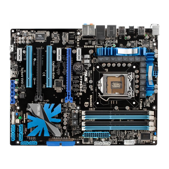
Page 20: Motherboard Overview
Motherboard overview 2.2.1 Motherboard layout Refer to 2.8 Connectors for more information about rear panel connectors and internal connectors. Chapter 2: Hardware information…
-
Page 21: Layout Contents
USB connectors (10-1 pin USB910, USB1112, USB1314) 2-35 IO Level UP switch 2-25 IEEE 1394a port connector (10-1 pin IE1394_2) 2-36 Optical drive audio connector (4-pin CD) 2-35 Front panel audio connector (10-1 pin AAFP) 2-38 Digital audio connector (4-1 pin SPDIF_OUT) 2-38 ASUS P7P55D-E…
-
Page 22: Placement Direction
2.2.3 Placement direction When installing the motherboard, ensure that you place it into the chassis in the correct orientation. The edge with external ports goes to the rear part of the chassis as indicated in the image below. 2.2.4 Screw holes Place nine screws into the holes indicated by circles to secure the motherboard to the chassis.
-
Page 23: Central Processing Unit (Cpu)
Contact your retailer immediately if the PnP cap is missing, or if you see any damage to the PnP cap/socket contacts/motherboard components. ASUS will shoulder the cost of repair only if the damage is shipment/ transit-related.
-
Page 24
Lift the load lever in the direction of the arrow until the load plate is completely lifted. Load plate Remove the PnP cap from the CPU socket by lifting the tab only. PnP cap Cap tab Position the CPU over the socket, ensuring that the gold triangle is on the bottom-left corner of the socket, and then CPU notches… -
Page 25
Close the load plate (A), and then push down the load lever (B), ensuring that the front edge of the load plate slides under the retention knob (C). Insert the load lever under the retention tab. ASUS P7P55D-E… -
Page 26: Installing The Cpu Heatsink And Fan
2.3.2 Installing the CPU heatsink and fan The Intel LGA1156 processor requires a specially designed heatsink and fan assembly to ® ensure optimum thermal condition and performance. • When you buy a boxed Intel ® processor, the package includes the CPU fan and heatsink assembly.
-
Page 27: Uninstalling The Cpu Heatsink And Fan
Rotate each fastener counterclockwise. Pull up two fasteners at a time in a diagonal sequence to disengage the heatsink and fan assembly from the motherboard. Carefully remove the heatsink and fan assembly from the motherboard. ASUS P7P55D-E…
-
Page 28: System Memory
System memory 2.4.1 Overview The motherboard comes with four Double Data Rate 3 (DDR3) Dual Inline Memory Modules (DIMM) sockets. A DDR3 module has the same physical dimensions as a DDR2 DIMM but is notched differently to prevent installation on a DDR2 DIMM socket. DDR3 modules are developed for better performance with less power consumption.
-
Page 29: Memory Configurations
3.5 Ai Tweaker menu for manual memory frequency adjustment. • For system stability, use a more efficient memory cooling system to support a full memory load (4 DIMMs) or overclocking condition. ASUS P7P55D-E 2-11…
-
Page 30
P7P55D-E Motherboard Qualified Vendors Lists (QVL) DDR3-1067MHz capability for CPU at 2.66, 2.8 and 2.93GHz DIMM socket Chip Timing support (Optional) Vendor Part No. Size Chip NO. Voltage Brand Lable(Bios) CORSAIR CM3X1024-1066C7 1024MB DS Heat-Sink Package • • • Crucial CT12864BA1067.8FF 1024MB SS MICRON… -
Page 31
• Patriot PVT36G1333ELK 6144MB(Kit of 3) DS N/A Heat-Sink Package 9-9-9-24(1066-7-7-7-20) 1.65 • • • Silicon SP001GBLTU133S02 1024MB SS S-POWER I0YT3E0 9(1333-9-9-9-24) • • • Power Silicon SP002GBLTU133S02 2048MB DS S-POWER I0YT3E0 9(1333-9-9-9-24) • • • Power ASUS P7P55D-E 2-13… -
Page 32
P7P55D-E Motherboard Qualified Vendors Lists (QVL) DDR3-1600MHz capability for CPU at 2.66GHz DIMM socket Chip Timing support (Optional) Vendor Part No. Size Chip NO. Voltage Brand Dimm(Bios) A-DATA AD31600E001GMU 3072MB(Kit of 3) SS N/A Heat-Sink Package 8-8-8-24(1333-9-9-9-24) 1.65-1.85 • • •… -
Page 33
Patriot PVT36G1600ELK 6144MB(Kit of 3) DS N/A Heat-Sink Package 9-9-9-24(1066-7-7-7-20) 1.65 • • • Patriot PVT36G1600ELK 6144MB(Kit of 3) DS N/A Heat-Sink Package 9-9-9-24(1600-7-7-7-20) 1.65 • • • MFADR401PA0102(XMP) 2048MB DS SAMSUNG K4B1G08460 1066-8-8-8-20 • • • ASUS P7P55D-E 2-15… -
Page 34
P7P55D-E Motherboard Qualified Vendors Lists (QVL) DDR3-1625MHz capability for CPU at 2.66GHz DIMM socket Chip Timing support (Optional) Vendor Part No. Size SS/DS Chip NO. Voltage Brand Dimm(Bios) KINGSTON KHX13000D3LLK2/2GN(EPP) 2048MB(Kit of 2) Heat-Sink Package • • • KINGSTON KHX13000D3LLK2/2GX(XMP) 2048MB(Kit of 2) Heat-Sink Package •… -
Page 35
2GB(Kit of 2) SS Heat-Sink Package 8 • • OCZ3P20002GK(EPP) 2GB(Kit of 2) SS Heat-Sink Package 9 • • OCZ3P2000EB2GK 2GB(Kit of 2) SS Heat-Sink Package 9-8-8(1066-8-7-7-20) • • Gingle 9CAASS37AZZ01D1 DS N/A Heat-Sink Package 9-9-9-24 • • • ASUS P7P55D-E 2-17… -
Page 36
Hyper DIMM support is subject to the physical characteristics of individual CPUs. • According to Intel spec definition, DDR3-1600 is supported for one DIMM per channel only. ASUS exclusively provides two DDR3-1600 DIMM support for each memory channel. • According to Intel CPU spec, CPUs with a core frequency of 2.66G support the maximum DIMM frequency of up to DDR3-1333. -
Page 37: Installing A Dimm
Press the retaining clip outward to unlock the DIMM. Support the DIMM lightly with your fingers when pressing the retaining clip. The DIMM might get damaged when it flips out with extra force. Remove the DIMM from the socket. ASUS P7P55D-E 2-19…
-
Page 38: Expansion Slots
Expansion slots In the future, you may need to install expansion cards. The following subsections describe the slots and the expansion cards that they support. Ensure to unplug the power cord before adding or removing expansion cards. Failure to do so may cause you physical injury and damage motherboard components.
-
Page 39: Interrupt Assignments
Levelup disabled or set shared to USB 3.0) SATA 6G Controller (IO shared Levelup set to SATA6G) JMicron ATA Controller shared 1394 Controller – – shared – – – – HD Audio – – – – – – shared – ASUS P7P55D-E 2-21…
-
Page 40: Pci Slots
2.5.4 PCI slots The PCI slots support cards such as a LAN card, SCSI card, USB card, and other cards that comply with PCI specifications. Refer to the figure below for the location of the slot. 2.5.5 PCI Express x1 slots This motherboard supports PCI Express x1 network cards, SCSI cards, and other cards that comply with the PCI Express specifications.
-
Page 41
We recommend that you provide sufficient power when running CrossFireX™ mode. See page 2-39 for details. • Connect a chassis fan to the motherboard connector labeled CHA_FAN1/2 when using multiple graphics cards for better thermal environment. See page 2-37 for details. ASUS P7P55D-E 2-23… -
Page 42: Onboard Switches
BIOS default settings. A messgae will appear during POST reminding you that the BIOS has been restored to its default settings. • We recommend that you download and update to the latest BIOS version from the ASUS website at www.asus.com after using the MemOK! function. 2-24 Chapter 2: Hardware information…
-
Page 43
Press the IO Level UP switch during POST will restart the system to apply speed changes. • If you press the IO Level UP switch in OS environment, you have to manually restart the system to apply speed changes. ASUS P7P55D-E 2-25… -
Page 44: Jumpers
Jumpers Clear RTC RAM (3-pin CLRTC) This jumper allows you to clear the Real Time Clock (RTC) RAM in CMOS. You can clear the CMOS memory of date, time, and system setup parameters by erasing the CMOS RTC RAM data. The onboard button cell battery powers the RAM data in CMOS, which include system setup information such as system passwords.
-
Page 45
BIOS voltage settings before you change the setting of the jumper. • The system may need a better cooling system, such as a water cooling system, to maintain stability under high voltage settings. ASUS P7P55D-E 2-27… -
Page 46: Connectors
Connectors 2.8.1 Rear panel connectors Rear panel connectors 1. PS/2 mouse port (green) 7. Optical S/PDIF Out port 2. USB 2.0 ports 1 and 2 8. External SATA port 3. USB 2.0 ports 3 and 4 9. IEEE 1394a port 4.
-
Page 47: Audio I/O Connections
Mic In Orange – – Center/Subwoofer Center/Subwoofer Black – Rear Speaker Out Rear Speaker Out Rear Speaker Out Gray – – – Side Speaker Out 2.8.2 Audio I/O connections Audio I/O ports Connect to Headphone and Mic ASUS P7P55D-E 2-29…
-
Page 48
Connect to Stereo Speakers Connect to 2.1 channel Speakers Connect to 4.1 channel Speakers 2-30 Chapter 2: Hardware information… -
Page 49
Connect to 5.1 channel Speakers Connect to 7.1 channel Speakers ASUS P7P55D-E 2-31… -
Page 50: Internal Connectors
2.8.3 Internal connectors IDE connector (40-1 pin PRI_EIDE) The onboard IDE connector is for the Ultra DMA 133/100/66 signal cable. There are three connectors on each Ultra DMA 133/100/66 signal cable: blue, black, and gray. Connect the blue connector to the motherboard’s IDE connector, then select one of the following modes to configure your device.
-
Page 51
The Serial ATA RAID feature (RAID 0, 1, 5, and 10) is available only if you are using Windows XP SP2 or later version. ® When using hot-plug and NCQ, set the Configure SATA as item in the BIOS to • [AHCI]. See section 3.4.2 Storage Configuration for details. ASUS P7P55D-E 2-33… -
Page 52
JMicron JMB363 Serial ATA connector (7-pin SATA_E1 [black]) ® This connector connects to a Serial ATA hard disk drive or optical disc drive via a Serial ATA signal cable. To enable hot-plugging, set the J-Micron Controller item in the BIOS setting to [AHCI Mode], and then reboot the system. -
Page 53
Never connect a 1394 cable to the USB connectors. Doing so will damage the motherboard! You can connect the front panel USB cable to the ASUS Q-Connector (USB, blue) first, and then install the Q-Connector (USB) to the USB connector onboard if your chassis supports front panel USB ports. -
Page 54
IEEE 1394a port connector (10-1 pin IE1394_2) This connector is for an IEEE 1394a port. Connect the IEEE 1394a module cable to this connector, then install the module to a slot opening at the back of the system chassis. Never connect a USB cable to the IEEE 1394a connector. Doing so will damage the motherboard! The IEEE 1394a module is purchased separately. -
Page 55
Only the CPU_FAN, CHA_FAN 1, and CHA_FAN 2 connectors support the FAN Xpert feature. • If you install two VGA cards, we recommend that you plug the rear chassis fan cable to the motherboard connector labeled CHA_FAN1 or CHA_FAN2 for better thermal environment. ASUS P7P55D-E 2-37… -
Page 56
Digital audio connector (4-1 pin SPDIF_OUT) This connector is for an additional Sony/Philips Digital Interface (S/PDIF) port(s). Connect the S/PDIF Out module cable to this connector, then install the module to a slot opening at the back of the system chassis. The S/PDIF module is purchased separately. -
Page 57
• If you are uncertain about the minimum power supply requirement for your system, refer to the Recommended Power Supply Wattage Calculator at http://support.asus. com/PowerSupplyCalculator/PSCalculator.aspx?SLanguage=en-us for details. • If you want to use two or more high-end PCI Express x16 cards, use a PSU with 1000W power or above to ensure the system stability. -
Page 58: System Panel Connector 20-8 Pin Panel
System panel connector (20-8 pin PANEL) This connector supports several chassis-mounted functions. • System power LED (2-pin PLED) This 2-pin connector is for the system power LED. Connect the chassis power LED cable to this connector. The system power LED lights up when you turn on the system power, and blinks when the system is in sleep mode.
-
Page 59: Asus Q-Connector (System Panel)
2.8.4. ASUS Q-Connector (system panel) Use the ASUS Q-Connector to connect/disconnect the chassis front panel cables. To install the ASUS Q-Connector Connect the front panel cables to the ASUS Q-Connector. Refer to the labels on the Q-Connector to know the detailed pin definitions, and then match them to their respective front panel cable labels.
-
Page 60: Onboard Leds
Onboard LEDs POST State LEDs POST State LEDs check key components (CPU, DRAM, VGA card, and HDD) in sequence during motherboard booting process. If an error is found , the LED next to the error device will continue lighting until the problem is solved. This user-friendly design provides an intuitive way to locate the root problem within seconds.
-
Page 61: Starting Up For The First Time
BIOS setting. Pressing the power switch for more than four seconds lets the system enter the soft-off mode regardless of the BIOS setting. Refer to section 3.7 Power Menu in Chapter 3 for details. ASUS P7P55D-E 2-43…
-
Page 62
2-44 Chapter 2: Hardware information… -
Page 63: Chapter 3: Bios Setup
Refer to the corresponding sections for details on these utilities. Save a copy of the original motherboard BIOS file to a USB flash drive in case you need to restore the BIOS in the future. Copy the original motherboard BIOS using the ASUS Update utility.
-
Page 64: Asus Update Utility
3.2.1 ASUS Update utility The ASUS Update is a utility that allows you to manage, save, and update the motherboard BIOS in Windows environment. The ASUS Update utility allows you to: ® • Save the current BIOS file • Download the latest BIOS file from the Internet •…
-
Page 65: Updating Bios Through Bios File
Auto Select. Click Next. Next. Follow the onscreen instructions to complete the update process. The ASUS Update utility is capable of updating itself through the Internet. Always update the utility to avail all its features. Updating the BIOS through a BIOS file…
-
Page 66: Asus Ez Flash 2 Utility
3.2.2 ASUS EZ Flash 2 utility The ASUS EZ Flash 2 feature allows you to update the BIOS without using an OS-based utility. Before you start using this utility, download the latest BIOS from the ASUS website at www. asus.com.
-
Page 67: Asus Bios Updater
3.2.3 ASUS BIOS Updater The ASUS BIOS Updater allows you to update BIOS in DOS environment. This utility also allows you to copy the current BIOS file that you can use as a backup when the BIOS fails or gets corrupted during the updating process.
-
Page 68
Backing up the current BIOS To backup the current BIOS file using the BIOS Updater Ensure that the USB flash drive is not write-protected and has enough free space to save the file. At the FreeDOS prompt, type bupdater /o[filename] and press <Enter>. D:>bupdater /oOLDBIOS1.rom Filename Extension The [filename] is any user-assigned filename with no more than eight alphanumeric… -
Page 69
Select the Load Setup Defaults item under the Exit BIOS menu. See Chaper 3 of your motherboard user manual for details. • Ensure to connect all SATA hard disk drives after updating the BIOS file if you have disconnected them. ASUS P7P55D-E… -
Page 70: Asus Crashfree Bios 3 Utility
The BIOS file in the motherboard support DVD may be older than the BIOS file published on the ASUS official website. If you want to use the newer BIOS file, download the file at support.asus.com and save it to a USB flash drive.
-
Page 71: Bios Menu Screen
For changing the advanced system settings Power For changing the advanced power management (APM) configuration Boot For changing the system boot configuration Tools For configuring options for special functions Exit For selecting the exit options and loading default settings ASUS P7P55D-E…
-
Page 72: Navigation Keys
3.3.3 Navigation keys At the bottom right corner of a menu screen are the navigation keys for that particular menu. Use the navigation keys to select items in the menu and change the settings. The navigation keys may differ from one screen to another. 3.3.4 Menu items The highlighted item on the menu bar displays the specific items for that menu.
-
Page 73: Main Menu
(C)Copyright 1985-2009, American Megatrends, Inc. The BIOS automatically detects the values of the dimmed items (Device, Vendor, Size, LBA Mode, Block Mode, PIO Mode, Async DMA, Ultra DMA, and SMART monitoring). These values are not user-configurable. ASUS P7P55D-E 3-11…
-
Page 74
Type [Auto] Allows you to select the type of SATA drive installed. [Not Installed] Select this option if no SATA drive is installed. [Auto] Allows automatic selection of the appropriate SATA device type. [CDROM] Select this option if you are specifically configuring a CD-ROM drive. [ARMD] Select [ARMD] (ATAPI Removable Media Device) if your device is a ZIP, LS-120, or MO drive. -
Page 75: Storage Configuration
AHCI Settings Some SATA CD/DVD in AHCI mode need to wait ready longer. SATA Port1 [Not Detected] SATA Port2 [Not Detected] SATA Port3 [Not Detected] SATA Port4 [Not Detected] SATA Port5 [Not Detected] SATA Port6 [Not Detected] ASUS P7P55D-E 3-13…
-
Page 76: System Information
SATA Port1–6 [XXXX] Displays the status of auto-detection of SATA devices. BIOS SETUP UTILITY Main Select the type SATA Port1 of devices connected Device :Not Detected to the system. SATA Port1 [Auto] SMART Monitoring [Enabled] SATA Port1 [Auto] Allows you to select the type of device connected to the system. Configuration options: [Auto] [Not Installed] SMART Monitoring [Enabled] Allows you to set the Self-Monitoring, Analysis and Reporting Technology.
-
Page 77: Ai Tweaker Menu
[Auto] want to adjust more, DRAM Frequency [Auto] set Ai Overclock Tuner QPI Frequency [Auto] to Manual after you ASUS/3rd Party UI Priority [ASUS Utility] select a CPU level. OC Tuner [Turbo Profile] Select Screen ←→ Start auto tuning Select Item ↑↓…
-
Page 78: Ai Overclock Tuner
D.O.C.P. D.O.C.P. • When using DIMMs with a frequncy higher than the Intel CPU spec, use this ASUS ® exclusive DRAM O.C. Profile function to overclock the DRAM. • Adjust BCLK frequency to obtain a better performance after applying the D.O.C.P function.
-
Page 79: Cpu Ratio Setting
2.66G CPU, enable the DRAM O.C. Profile feature in BIOS. Refer to section 3.5.2 Ai Overclock Tuner for details. Selecting a very high DRAM frequency may cause the system to become unstable! If this happens, revert to the default setting. ASUS P7P55D-E 3-17…
-
Page 80: Qpi Frequency
[ASUS Utility] Prioritizes the usage of ASUS utilities (ASUS EPU, TurboV EVO, etc.). Other 3rd party OC utilities may not be full-functioned. [3rd Party Utility] Prioritizes 3rd party OC utilities (IXTU, SetFS, etc.). ASUS utilities can’t be launched. 3.5.10 OC Tuner [Turbo Profile] OC Tuner automatically overclocks the frequency and voltage of CPU and DRAM.
-
Page 81
Configuration options: [Auto] [2 DRAM Clock] – [14 DRAM Clock] DRAM READ to WRITE Delay(SR) [Auto] Configuration options: [Auto] [2 DRAM Clock] – [14 DRAM Clock] DRAM READ to READ Delay(DD) [Auto] Configuration options: [Auto] [2 DRAM Clock] – [9 DRAM Clock] ASUS P7P55D-E 3-19… -
Page 82: Cpu Differential Amplitude
DRAM READ to READ Delay(DR) [Auto] Configuration options: [Auto] [2 DRAM Clock] – [9 DRAM Clock] DRAM READ to READ Delay(SR) [Auto] Configuration options: [Auto] [4 DRAM Clock] [6 DRAM Clock] DRAM WRITE to WRITE Delay(DD) [Auto] Configuration options: [Auto] [2 DRAM Clock] – [9 DRAM Clock] DRAM WRITE to WRITE Delay(DR) [Auto] Configuration options: [Auto] [2 DRAM Clock] –…
-
Page 83: Imc Voltage
IMC Voltage 1.16875V 1.22500V 1.30000V 1.70000V 1.2000V– 1.5750V– 1.6375V– 1.7000V– DRAM Voltage 1.5625V 1.6250V 1.6875V 2.5000V 1.8000V– 1.8750V– 1.9375- 2.0000V– CPU PLL Voltage 1.8625V 1.9250V 1.9875 2.5000V 1.0500V- 1.2000V 1.3125V 1.4625V- PCH Voltage 1.1875V 1.3000V 1.4500V 1.5000V ASUS P7P55D-E 3-21…
-
Page 84: Dram Data Ref Voltage On Cha/B
3.5.20 DRAM DATA REF Voltage on CHA/B [Auto] Allows you to set the DRAM DATA Reference Voltage on Channel A/B. The values range from 0.395x to 0.630x with a 0.005x interval. Different ratio might enhance DRAM overclocking ability. 3.5.21 DRAM CTRL REF Voltage on CHA/B [Auto] Allows you to set the DRAM Control Reference Voltage on Channel A/B.
-
Page 85: Advanced Menu
Execute-Disable Bit Capability [Enabled] Intel(R) HT Technology [Enabled] Active Processor Cores [All] A20M [Disabled] Intel(R) SpeedStep(TM) Tech [Enabled] Intel(R) Turbo Mode Tech [Enabled] Intel(R) C-STATE Tech [Disabled] C State package limit setting [Auto] v02.61 (C)Copyright 1985-2009, American Megatrends, Inc. ASUS P7P55D-E 3-23…
-
Page 86
CPU Ratio Setting [Auto] Allows you to adjust the ratio between CPU Core Clock and BCLK Frequency. Use the <+> and <-> keys to adjust the value. The valid value ranges differently according to your CPU model. C1E Support [Enabled] [Enabled] Enables the C1E support function. -
Page 87: Uncore Configuration
PCI devices to be remapped above the total physical memory. Fast MRC [Disabled] [Enabled] While cold booting, MRC directly restores memory data from valid NVRAM without hardware training. [Disabled] The cold booting with memory detection and hardware training. ASUS P7P55D-E 3-25…
-
Page 88: Onboard Device Configuration
3.6.3 Onboard Device Configuration BIOS SETUP UTILITY Advanced Onboard Devices Configuration Options HDA Controller [Enabled] Front Panel Type [HD Audio] Enabled Realtek LAN1 [Enabled] Disabled LAN Boot ROM [Disabled] Onboard 1394 Controller [Enabled] J-Micron SATA/PATA Controller [Enabled] JMB Boot ROM [Auto] Serial Port1 Address [3F8/IRQ4]…
-
Page 89: Usb Configuration
USB controller legacy mode is enabled. If no USB device is detected, the legacy USB support is disabled. BIOS EHCI Hand-off [Enabled] [Disabled] Disables the function. [Enabled] Enables the support for operating systems without an EHCI hand-off feature. ASUS P7P55D-E 3-27…
-
Page 90: Pcipnp
3.6.5 PCIPnP The PCIPnP menu items allow you to change the advanced settings for PCI/PnP devices. BIOS SETUP UTILITY Advanced Advanced PCI/PnP Settings NO: lets the BIOS configure all the WARNING: Setting wrong values in below sections devices in the may cause system to malfunction.
-
Page 91: Power Menu
EuP Ready [Disabled] [Disabled] Disables the Energy Using Products (EuP) Ready function. [Enabled] Allows the BIOS to switch off power for WOL, WO_USB, audio, and onboard LEDs at S5 state to get the system ready for the EuP requirement. ASUS P7P55D-E 3-29…
-
Page 92: Apm Configuration
3.7.6 APM Configuration BIOS SETUP UTILITY Power APM Configuration <Enter> to select whether or not to Restore on AC Power Loss [Power Off] restart the system Power On By RTC Alarm [Disabled] after AC power loss. Power On By External Modems [Disalbed] Power On By PCI Devices [Disabled]…
-
Page 93: Hardware Monitor
CPU temperature. [Silent] Sets to [Silent] to minimize the fan speed for quiet CPU fan operation. [Turbo] Set to [Turbo] to achieve maximum CPU fan speed. [Manual] Set to [Manual] to assign detailed fan speed control parameters. ASUS P7P55D-E 3-31…
-
Page 94: Boot Menu
Chassis Q-Fan Control [Disabled] [Disabled] Disables the Chassis Q-Fan control feature. [Enabled] Enables the Chassis Q-Fan control feature. Chassis Fan Profile [Standard] This item appears only when you enable the Chassis Q-Fan Control feature and allows you to set the appropriate performance level of the chassis fan. [Standard] Sets to [Standard] to make the chassis fan automatically adjust depending on the chassis temperature.
-
Page 95: Boot Settings Configuration
Disables the full screen logo display feature. [Enabled] Enables the full screen logo display feature. Set this item to [Enabled] to use the ASUS MyLogo 2™ feature. AddOn ROM Display Mode [Force BIOS] [Force BIOS] The third-party ROM messages will be forced to display during the boot sequence.
-
Page 96: Security
3.8.3 Security The Security menu items allow you to change the system security settings. Select an item then press <Enter> to display the configuration options. BIOS SETUP UTILITY Boot Security Settings <Enter> to change password. Supervisor Password : Not Installed <Enter>…
-
Page 97
Clear User Password Select this item to clear the user password. Password Check [Setup] [Setup] BIOS checks for user password when accessing the Setup utility. [Always] BIOS checks for user password both when accessing Setup and booting the system. ASUS P7P55D-E 3-35… -
Page 98: Tools Menu
<Enter> to display the submenu. BIOS SETUP UTILITY Main Ai Tweaker Advanced Power Boot Tools Exit ASUS O.C. Profile AI NET 2 ASUS EZ Flash 2 Express Gate [Auto] Enter OS Timer [10 Seconds] Reset User Data [No] IO Levelup [Disabled] Select Screen ←→…
-
Page 99: Ai Net 2
3.9.3 ASUS EZ Flash 2 Allows you to run ASUS EZ Flash 2. When you press <Enter>, a confirmation message appears. Use the left/right arrow key to select between [Yes] or [No], then press <Enter> to confirm your choice. Check section 3.2.2 ASUS EZ Flash 2 utility for details.
-
Page 100: Express Gate
3.9.4 Express Gate [Auto] Allows you to enable or disable the ASUS Express Gate feature. The ASUS Express Gate feature is a unique instant-on environment that provides quick access to the Internet browser and Skype. Configuration options: [Enabled] [Disabled] [Auto] Enter OS Timer [10 Seconds] Sets countdown duration that the system waits at the Express Gate’s first screen…
-
Page 101: Exit Menu
When you select this option or if you press <F5>, a confirmation window appears. Select Ok to load default values. Select Exit & Save Changes or make other changes before saving the values to the non-volatile RAM. ASUS P7P55D-E 3-39…
-
Page 102
3-40 Chapter 3: BIOS setup… -
Page 103: Chapter 4: Software Support
The contents of the support DVD are subject to change at any time without notice. Visit the ASUS website at www.asus.com for updates. 4.2.1 Running the support DVD Place the support DVD into the optical drive.
-
Page 104: Obtaining The Software Manuals
The software manual files are in Portable Document Format (PDF). Install the Adobe ® Acrobat Reader from the Utilities menu before opening the files. ® Click the Manual tab. Click ASUS Motherboard Utility Guide from the manual list on the left. The Manual folder of the support DVD appears. Double-click the folder of your selected software.
-
Page 105: Software Information
Launching PC Probe II Install PC Probe II from the motherboard support DVD. Launch PC Probe II by clicking Start > All Programs > ASUS > PC Probe II > PC Probe II v1.xx.xx. The PC Probe II main window appears.
-
Page 106: Asus Ai Suite
Launching AI Suite Install AI Suite from the motherboard support DVD. Launch AI Suite by clicking Start > All Programs > ASUS > AI Suite > AI Suite v1.xx. xx. The AI Suite main window appears. The AI Suite icon appears in the Windows notification area.
-
Page 107: Asus Fan Xpert
4.3.3 ASUS Fan Xpert Asus Fan Xpert allows you to adjust both the CPU and chassis fan speeds according to different ambient temperatures and your PC’s system loading. The various fan profiles offer flexible controls of fan speeds to achieve a quiet and cool system environment.
-
Page 108: Asus Epu-6 Engine
4.3.4 ASUS EPU-6 Engine ASUS EPU-6 Engine is an energy-efficient tool that satisfies different computing needs. This utility provides four modes that you can select to enhance system performance or save power: Turbo Mode • Medium Power Saving Mode •…
-
Page 109: Asus Express Gate
4.3.5 ASUS Express Gate ASUS Express Gate is an instant-on environment that gives you quick access to the Internet, Skype, and viewing your pictures. Within a few seconds of powering on your computer, you will be at the Express Gate menu where you can start the web browser, Skype, or other Express Gate applications.
-
Page 110: Asus T.probe
Follow the screen instructions to complete installation. Before using ASUS T.Probe You have to configure BIOS settings before using ASUS T.Probe. Press <Del> during the Power-On Self Test (POST) to enter the Setup utility. Set the T.Probe item in the Advanced menu to [Enabled] Save BIOS settings and restart the computer.
-
Page 111: Via ® High Definition Audio Utility
VIA HD Audio Deck for Windows XP Display panel and volume control Minimize button Configuration options Control settings window Refer to the software manual in the support DVD or visit the ASUS website at www.asus.com for detailed software configuration. ASUS P7P55D-E…
-
Page 112: Intel ® Extreme Tuning Utility
Extreme Tuning Utility (IXTU) allows easy overclocking for your system. To use ® IXTU, first set the ASUS/3rd Party UI Priority item in the Ai Tweaker BIOS menu to [3rd Party Utility] and install IXTU from the motherboard support DVD.
-
Page 113: Raid Configurations
You can also combine two RAID sets to get higher performance, capacity, or fault tolerance provided by the difference RAID function. For example, RAID 0 and RAID 1 set can be created by using only two identical hard disk drives. ASUS P7P55D-E 4-11…
-
Page 114: Installing Serial Ata Hard Disks
4.4.2 Installing Serial ATA hard disks The motherboard supports Serial ATA hard disk drives. For optimal performance, install identical drives of the same model and capacity when creating a disk array. To install the SATA hard disks for a RAID configuration: Install the SATA hard disks into the drive bays.
-
Page 115: Creating A Raid Volume
Status ST3160812AS 9LS0HJA4 149.0GB Non-RAID Disk ST3160812AS 9LS0F4HL 149.0GB Non-RAID Disk ST3160812AS 3LS0JYL8 149.0GB Non-RAID Disk ST3160812AS 9LS0BJ5H 149.0GB Non-RAID Disk Select 2 to 6 disks to use in creating the volume. [ ↑↓ ]-Prev/Next [SPACE]-SelectDisk [ENTER]-Done ASUS P7P55D-E 4-13…
-
Page 116
Use the up/down arrow key to select a drive, and then press <Space> to select. A small triangle marks the selected drive. Press <Enter> after completing your selection. Use the up/down arrow key to select the stripe size for the RAID array (for RAID 0, 10 and 5 only), and then press <Enter>. -
Page 117
From the utility main menu, select 5. Exit, and then press <Enter>. The following warning message appears. CONFIRM EXIT Are you sure you want to exit? (Y/N): Press <Y> to exit or press <N> to return to the utility main menu. ASUS P7P55D-E 4-15… -
Page 118: Creating A Raid Driver Disk
Creating a RAID driver disk A floppy disk with the RAID driver is required when installing Windows XP operating system ® on a hard disk drive that is included in a RAID set. For Windows Vista or later operating ® systems, use either a floppy disk or a USB flash drive with the RAID driver.
-
Page 119: Installing The Raid Driver During Windows ® Os Installation
Manage from the pop-up window. Select Device Manager. From the Universal Serial Bus controllers, right-click xxxxxx USB Floppy, and then select Properties from the pop-up window. The name of the USB floppy disk drive varies with different vendors. ASUS P7P55D-E 4-17…
-
Page 120
Click Details tab. The Vendor ID (VID) and Product ID (PID) are displayed. Browse the contents of the RAID driver disk to locate the file txtsetup.oem. Double-click the file. A window appears, allowing you to select the program for opening the oem file. Use Notepad to open the file. -
Page 121
Type the following line to the bottom of the two sections: id = “USBVID_xxxx&PID_xxxx”, “usbstor” [HardwareIds.scsi.iaAHCI_PCH] id= “PCIVEN_8086&DEV_3A22&CC_0106”,”iaStor” id= “USBVID_03EE&PID_6901”, “usbstor” [HardwareIds.scsi.iaStor_8R9R10RDOPCH] id= “PCIVEN_8086&DEV_3A22&CC_0106”,”iaStor” id= “USBVID_03EE&PID_6901”, “usbstor” Add the same line to both sections. The VID and PID vary with different vendors. Save and exit the file. ASUS P7P55D-E 4-19… -
Page 122
4-20 Chapter 4: Software support… -
Page 123: Chapter 5: Ati ® Crossfirex™ Technology Support
For Windows XP, go to Control Panel > Add/Remove Programs. For Windows Vista, go to Control Panel > Programs and Features. Select your current graphics card driver/s. For Windows XP, select Add/Remove. For Windows Vista, select Uninstall. Turn off your computer. ASUS P7P55D-E…
-
Page 124: Installing Crossfirex™ Graphics Cards
Installing CrossFireX™ graphics cards The following pictures are for reference only. The graphics cards and the motherboard layout may vary with models, but the installation steps remain the same. Prepare two CrossFireX-ready graphics cards. Insert the two graphics card into the PCIEX16 slots.
-
Page 125: Software Information
ATI icon in the Windows notification area and select Cayalist Control Center. The Catalyst Control Center Setup Assistant appears when the system detects the existance of multi-graphics cards. Click Go to continue to the Catalyst Control Center Advanced View window. ASUS P7P55D-E…
-
Page 126
Enabling Dual CrossFireX settings In the Catalyst Control Center window, click Graphics Settings > CrossFireX > Configure. From the Graphics Adapter list, select the graphics card to act as the display GPU. Select Enable CrossFireX. Click Apply, and then click OK to exit the window.
-
Драйверы
45
-
Инструкции по эксплуатации
6
Языки:

ASUS P7P55D-E инструкция по эксплуатации
(126 страниц)
- Языки:Английский
-
Тип:
PDF -
Размер:
8.45 MB -
Описание:
P7P55D-E user’s manual (English)
Просмотр

ASUS P7P55D-E инструкция по эксплуатации
(1 страница)
- Языки:Английский
-
Тип:
PDF -
Размер:
388.24 KB
Просмотр

ASUS P7P55D-E инструкция по эксплуатации
(126 страниц)
- Языки:Немецкий
-
Тип:
PDF -
Размер:
10.81 MB -
Описание:
P7P55D-E user’s manual (German)
Просмотр

ASUS P7P55D-E инструкция по эксплуатации
(126 страниц)
- Языки:Японский
-
Тип:
PDF -
Размер:
6.88 MB -
Описание:
P7P55D-E user’s manual (Japanese)
Просмотр

ASUS P7P55D-E инструкция по эксплуатации
(126 страниц)
- Языки:Французский
-
Тип:
PDF -
Размер:
6.1 MB -
Описание:
P7P55D-E user’s manual (French)
Просмотр

ASUS P7P55D-E инструкция по эксплуатации
(128 страниц)
- Языки:Китайский
-
Тип:
PDF -
Размер:
11.65 MB -
Описание:
P7P55D-E user’s manual (Simplified Chinese)
Просмотр
На NoDevice можно скачать инструкцию по эксплуатации для ASUS P7P55D-E. Руководство пользователя необходимо для ознакомления с правилами установки и эксплуатации ASUS P7P55D-E. Инструкции по использованию помогут правильно настроить ASUS P7P55D-E, исправить ошибки и выявить неполадки.
![]()

E5133
First Edition
November 2009
Copyright © 2009 ASUSTeK COMPUTER INC. All Rights Reserved.
No part of this manual, including the products and software described in it, may be reproduced, transmitted, transcribed, stored in a retrieval system, or translated into any language in any form or by any means, except documentation kept by the purchaser for backup purposes, without the express written permission of ASUSTeK COMPUTER INC. (“ASUS”).
Product warranty or service will not be extended if: (1) the product is repaired, modified or altered, unless such repair, modification of alteration is authorized in writing byASUS; or (2) the serial number of the product is defaced or missing.
ASUS PROVIDES THIS MANUAL “AS IS” WITHOUT WARRANTY OF ANY KIND, EITHER EXPRESS OR IMPLIED, INCLUDING BUT NOT LIMITED TO THE IMPLIED WARRANTIES OR CONDITIONS OF MERCHANTABILITY OR FITNESS FOR A PARTICULAR PURPOSE. IN NO EVENT SHALL ASUS, ITS DIRECTORS, OFFICERS, EMPLOYEES OR AGENTS BE LIABLE FOR ANY INDIRECT, SPECIAL, INCIDENTAL, OR CONSEQUENTIAL DAMAGES (INCLUDING DAMAGES FOR LOSS OF PROFITS, LOSS OF BUSINESS, LOSS OF USE OR DATA, INTERRUPTION OF BUSINESS AND THE LIKE), EVEN IF ASUS HAS BEEN ADVISED OF THE POSSIBILITY OF SUCH DAMAGES ARISING FROM ANY DEFECT OR ERROR IN THIS MANUAL OR PRODUCT.
SPECIFICATIONS AND INFORMATION CONTAINED IN THIS MANUAL ARE FURNISHED FOR INFORMATIONAL USE ONLY, AND ARE SUBJECT TO CHANGE AT ANY TIME WITHOUT NOTICE, AND SHOULD NOT BE CONSTRUED AS A COMMITMENT BY ASUS. ASUS ASSUMES NO RESPONSIBILITY OR LIABILITY FOR ANY ERRORS OR INACCURACIES THAT MAY APPEAR IN THIS MANUAL, INCLUDING THE PRODUCTS AND SOFTWARE DESCRIBED IN IT.
Products and corporate names appearing in this manual may or may not be registered trademarks or copyrights of their respective companies, and are used only for identification or explanation and to the owners’ benefit, without intent to infringe.
ii

Contents
|
Notices viii |
|
|
Safety information………………………………………………………………………………………… |
ix |
|
About this guide…………………………………………………………………………………………….. |
x |
|
P7P55D-E Deluxe specifications summary……………………………………………………. |
xii |
|
Chapter 1: |
Product introduction |
||
|
1.1 |
Welcome! |
……………………………………………………………………………………….. |
1-1 |
|
1.2 |
Package contents…………………………………………………………………………… |
1-1 |
|
|
1.3 |
Special features……………………………………………………………………………… |
1-2 |
|
|
1.3.1 ……………………………………………………………… |
Product highlights |
1-2 |
|
|
1.3.2 …………………………….. |
ASUS Xtreme Design—Hybrid Processor |
1-3 |
|
|
1.3.3 ……………………………… |
ASUS Xtreme Design—24 Hybrid Phase |
1-3 |
|
|
1.3.4 ………………………………………. |
ASUS Xtreme Design—Hybrid OS |
1-3 |
|
|
1.3.5 …………………………………………………… |
ASUS Exclusive Features |
1-4 |
|
Chapter 2: |
Hardware information |
||
|
2.1 |
Before you proceed………………………………………………………………………… |
2-1 |
|
|
2.2 |
Motherboard overview……………………………………………………………………. |
2-2 |
|
|
2.2.1 |
Motherboard layout……………………………………………………………. |
2-2 |
|
|
2.2.2 |
Layout contents.……………………………………………………………….. |
2-3 |
|
|
2.2.3 |
Placement direction…………………………………………………………… |
2-4 |
|
|
2.2.4 |
Screw holes……………………………………………………………………… |
2-4 |
|
|
2.3 |
Central Processing Unit (CPU)………………………………………………………… |
2-5 |
|
|
2.3.1 |
Installing the CPU……………………………………………………………… |
2-5 |
|
|
2.3.2 |
Installing the CPU heatsink and fan……………………………………… |
2-8 |
|
|
2.3.3 |
Uninstalling the CPU heatsink and fan…………………………………. |
2-9 |
|
|
2.4 |
System memory……………………………………………………………………………. |
2-10 |
|
|
2.4.1 |
Overview………………………………………………………………………… |
2-10 |
|
|
2.4.2 |
Memory configurations.……………………………………………………. |
2-11 |
|
|
2.4.3 |
Installing a DIMM…………………………………………………………….. |
2-20 |
|
|
2.4.4 |
Removing a DIMM…………………………………………………………… |
2-20 |
|
|
2.5 |
Expansion slots……………………………………………………………………………. |
2-21 |
|
|
2.5.1 |
Installing an expansion card……………………………………………… |
2-21 |
|
|
2.5.2 |
Configuring an expansion card………………………………………….. |
2-21 |
|
|
2.5.3 |
Interrupt assignments………………………………………………………. |
2-22 |
|
|
2.5.4 |
PCI slots.……………………………………………………………………….. |
2-23 |
|
|
2.5.5 |
PCI Express 2.0 x1 slots…………………………………………………… |
2-23 |
|
|
2.5.6 |
PCI Express 2.0 x16 slots…………………………………………………. |
2-23 |
|
|
2.6 |
Onboard switches…………………………………………………………………………. |
2-25 |
iii

Contents
|
2.7 |
Connectors…………………………………………………………………………………… |
2-28 |
|
|
2.7.1 |
Rear panel connectors……………………………………………………… |
2-28 |
|
|
2.7.2 |
Audio I/O connections………………………………………………………. |
2-29 |
|
|
2.7.3 |
Internal connectors………………………………………………………….. |
2-32 |
|
|
2.7.4. |
ASUS Q-Connector (system panel)……………………………………. |
2-42 |
|
|
2.8 |
Onboard LEDs………………………………………………………………………………. |
2-43 |
|
|
2.9 |
Starting up for the first time………………………………………………………….. |
2-44 |
|
|
2.10 |
Turning off the computer………………………………………………………………. |
2-44 |
|
Chapter 3: |
BIOS setup |
||
|
3.1 |
Knowing BIOS………………………………………………………………………………… |
3-1 |
|
|
3.2 |
Updating BIOS……………………………………………………………………………….. |
3-1 |
|
|
3.2.1 |
ASUS Update utility…………………………………………………………… |
3-2 |
|
|
3.2.2 |
ASUS EZ Flash 2 utility.…………………………………………………….. |
3-4 |
|
|
3.2.3 |
ASUS CrashFree BIOS 3 utility…………………………………………… |
3-5 |
|
|
3.2.4 |
ASUS BIOS Updater………………………………………………………….. |
3-6 |
|
|
3.3 |
BIOS setup program……………………………………………………………………….. |
3-9 |
|
|
3.3.1 |
BIOS menu screen.…………………………………………………………… |
3-9 |
|
|
3.3.2 |
Menu bar………………………………………………………………………….. |
3-9 |
|
|
3.3.3 |
Navigation keys.……………………………………………………………… |
3-10 |
|
|
3.3.4 |
Menu items…………………………………………………………………….. |
3-10 |
|
|
3.3.5 |
Submenu items……………………………………………………………….. |
3-10 |
|
|
3.3.6 |
Configuration fields………………………………………………………….. |
3-10 |
|
|
3.3.7 |
Pop-up window……………………………………………………………….. |
3-10 |
|
|
3.3.8 |
Scroll bar………………………………………………………………………… |
3-10 |
|
|
3.3.9 |
General help…………………………………………………………………… |
3-10 |
|
|
3.4 |
Main menu……………………………………………………………………………………. |
3-11 |
|
|
3.4.1 |
SATA 1–6……………………………………………………………………….. |
3-11 |
|
|
3.4.2 |
Storage Configuration………………………………………………………. |
3-13 |
|
|
3.4.3 |
AHCI Configuration………………………………………………………….. |
3-13 |
|
|
3.4.4 |
System Information………………………………………………………….. |
3-14 |
|
|
3.5 |
Ai Tweaker menu………………………………………………………………………….. |
3-15 |
|
|
3.5.1 |
CPU Level Up ………………………………………………………………… |
3-15 |
|
|
3.5.2 |
Ai Overclock Tuner .………………………………………………………… |
3-16 |
|
|
3.5.3 |
CPU Ratio Setting …………………………………………………………… |
3-17 |
|
|
3.5.4 |
Intel(R) SpeedStep(TM) Tech …………………………………………… |
3-17 |
|
|
3.5.5 |
Intel(R) TurboMode Tech .………………………………………………… |
3-17 |
|
|
3.5.6 |
Xtreme Phase Full Power Mode ……………………………………….. |
3-17 |
|
|
3.5.7 |
DRAM Frequency …………………………………………………………… |
3-17 |
iv

Contents
|
3.5.8 |
QPI Frequency ……………………………………………………………….. |
3-18 |
|
|
3.5.9 |
ASUS/3rd Party Ui Priority………………………………………………… |
3-18 |
|
|
3.5.10 |
OC Tuner……………………………………………………………………….. |
3-18 |
|
|
3.5.11 |
Start auto tuning.…………………………………………………………….. |
3-18 |
|
|
3.5.12 |
DRAM Timing Control………………………………………………………. |
3-18 |
|
|
3.5.13 |
CPU Differential Amplitude.………………………………………………. |
3-20 |
|
|
3.5.14 |
CPU Clock Skew .…………………………………………………………… |
3-20 |
|
|
3.5.15 |
CPU Voltage Mode………………………………………………………….. |
3-20 |
|
|
3.5.16 |
IMC Voltage……………………………………………………………………. |
3-21 |
|
|
3.5.17 |
DRAM Voltage………………………………………………………………… |
3-21 |
|
|
3.5.18 |
CPU PLL Voltage…………………………………………………………….. |
3-21 |
|
|
3.5.19 |
PCH Voltage ………………………………………………………………….. |
3-21 |
|
|
3.5.20 |
DRAM DATA REF Voltage on CHA/B ………………………………… |
3-22 |
|
|
3.5.21 |
DRAM CTRL REF Voltage on CHA/B ………………………………… |
3-22 |
|
|
3.5.22 |
Load-Line Calibration ………………………………………………………. |
3-22 |
|
|
3.5.23 |
CPU Spread Spectrum ……………………………………………………. |
3-22 |
|
|
3.5.24 |
PCIE Spread Spectrum .………………………………………………….. |
3-22 |
|
|
3.6 |
Advanced menu……………………………………………………………………………. |
3-23 |
|
|
3.6.1 |
CPU Configuration…………………………………………………………… |
3-23 |
|
|
3.6.2 |
Uncore Configuration……………………………………………………….. |
3-25 |
|
|
3.6.3 |
Onboard Devices Configuration…………………………………………. |
3-26 |
|
|
3.6.4 |
USB Configuration…………………………………………………………… |
3-27 |
|
|
3.6.5 |
PCIPnP………………………………………………………………………….. |
3-28 |
|
|
3.6.6 |
Intel VT-d .……………………………………………………………………… |
3-28 |
|
|
3.6.7 |
T.Probe .………………………………………………………………………… |
3-28 |
|
|
3.7 |
Power menu…………………………………………………………………………………. |
3-29 |
|
|
3.7.1 |
Suspend Mode ……………………………………………………………….. |
3-29 |
|
|
3.7.2 |
Repost Video on S3 Resume.…………………………………………… |
3-29 |
|
|
3.7.3 |
ACPI 2.0 Support…………………………………………………………….. |
3-29 |
|
|
3.7.4 |
ACPI APIC Support …………………………………………………………. |
3-29 |
|
|
3.7.5 |
EuP Ready …………………………………………………………………….. |
3-29 |
|
|
3.7.6 |
APM Configuration…………………………………………………………… |
3-30 |
|
|
3.7.7 |
Hardware Monitor……………………………………………………………. |
3-31 |
|
|
3.8 |
Boot menu……………………………………………………………………………………. |
3-33 |
|
|
3.8.1 |
Boot Device Priority…………………………………………………………. |
3-33 |
|
|
3.8.2 |
Boot Settings Configuration………………………………………………. |
3-34 |
|
|
3.8.3 |
Security………………………………………………………………………….. |
3-35 |
|
|
3.9 |
Tools menu…………………………………………………………………………………… |
3-37 |

Contents
|
3.9.1 |
ASUS O.C. Profile.………………………………………………………….. |
3-37 |
|
3.9.2 |
AI NET 2.……………………………………………………………………….. |
3-38 |
|
3.9.3 |
ASUS EZ Flash 2…………………………………………………………….. |
3-38 |
|
3.9.4 |
Express Gate …………………………………………………………………. |
3-39 |
|
3.9.5 |
ID LED ………………………………………………………………………….. |
3-39 |
|
3.10 Exit menu……………………………………………………………………………………… |
3-40 |
|
Chapter 4: |
Software support |
||
|
4.1 |
Installing an operating system………………………………………………………… |
4-1 |
|
|
4.2 |
Support DVD information………………………………………………………………… |
4-1 |
|
|
4.2.1 |
Running the support DVD…………………………………………………… |
4-1 |
|
|
4.2.2 |
Obtaining the software manuals………………………………………….. |
4-2 |
|
|
4.3 |
Software information………………………………………………………………………. |
4-3 |
|
|
4.3.1 |
ASUS PC Probe II.……………………………………………………………. |
4-3 |
|
|
4.3.2 |
ASUS AI Suite…………………………………………………………………… |
4-4 |
|
|
4.3.3 |
ASUS Fan Xpert……………………………………………………………….. |
4-5 |
|
|
4.3.4 |
ASUS EPU-6 Engine…………………………………………………………. |
4-6 |
|
|
4.3.5 |
ASUS Express Gate………………………………………………………….. |
4-7 |
|
|
4.3.6 |
ASUS T.Probe…………………………………………………………………… |
4-8 |
|
|
4.3.7 |
VIA® High DefinitionAudio utility………………………………………….. |
4-9 |
|
|
4.3.8 |
Intel® Extreme Tuning Utility.…………………………………………….. |
4-10 |
|
|
4.4 |
RAID configurations……………………………………………………………………… |
4-11 |
|
|
4.4.1 |
RAID definitions………………………………………………………………. |
4-11 |
|
|
4.4.2 |
Installing Serial ATA hard disks………………………………………….. |
4-12 |
|
|
4.4.3 |
Setting the RAID item in BIOS…………………………………………… |
4-12 |
|
|
4.4.4 |
Intel® Matrix Storage Manager option ROM utility.……………….. |
4-12 |
|
|
4.5 |
Creating a RAID driver disk…………………………………………………………… |
4-16 |
|
|
4.5.1 |
Creating a RAID driver disk without entering the OS…………….. |
4-16 |
|
|
4.5.2 |
Creating a RAID driver disk in Windows®.…………………………… |
4-16 |
|
|
4.5.3 |
Installing the RAID driver during Windows® OS installation……. |
4-17 |
|
|
4.5.4 |
Using a USB floppy disk drive.………………………………………….. |
4-17 |
|
Chapter 5: |
Multiple GPU technology support |
||
|
5.1 |
ATI® CrossFireX™ technology…………………………………………………………. |
5-1 |
|
|
5.1.1 |
Requirements.………………………………………………………………….. |
5-1 |
|
|
5.1.2 |
Before you begin……………………………………………………………….. |
5-1 |
|
|
5.1.3 |
Installing two CrossFireX™ graphics cards…………………………… |
5-1 |
|
|
5.1.4 |
Installing the device drivers.……………………………………………….. |
5-2 |
|
|
5.1.5 |
Enabling the ATI® CrossFireX™ technology………………………….. |
5-3 |
vi

Contents
|
5.2 |
NVIDIA® SLI™ technology……………………………………………………………….. |
5-4 |
|
|
5.2.1 |
Requirements.………………………………………………………………….. |
5-4 |
|
|
5.2.2 |
Installing two SLI-ready graphics cards………………………………… |
5-4 |
|
|
5.2.3 |
Installing the device drivers.……………………………………………….. |
5-5 |
|
|
5.2.4 |
Enabling the NVIDIA® SLI™ technology……………………………….. |
5-5 |
vii

Notices
Federal Communications Commission Statement
This device complies with Part 15 of the FCC Rules. Operation is subject to the following two conditions:
•This device may not cause harmful interference, and
•This device must accept any interference received including interference that may cause undesired operation.
This equipment has been tested and found to comply with the limits for a Class B digital device, pursuant to Part 15 of the FCC Rules. These limits are designed to provide reasonable protection against harmful interference in a residential installation. This equipment generates, uses and can radiate radio frequency energy and, if not installed and used in accordance with manufacturer’s instructions, may cause harmful interference to radio communications. However, there is no guarantee that interference will not occur in a particular installation. If this equipment does cause harmful interference to radio or
television reception, which can be determined by turning the equipment off and on, the user is encouraged to try to correct the interference by one or more of the following measures:
•Reorient or relocate the receiving antenna.
•Increase the separation between the equipment and receiver.
•Connect the equipment to an outlet on a circuit different from that to which the receiver is connected.
•Consult the dealer or an experienced radio/TV technician for help.
The use of shielded cables for connection of the monitor to the graphics card is required to assure compliance with FCC regulations. Changes or modifications to this unit not expressly approved by the party responsible for compliance could void the user’s authority to operate this equipment.
Canadian Department of Communications Statement
This digital apparatus does not exceed the Class B limits for radio noise emissions from digital apparatus set out in the Radio Interference Regulations of the Canadian Department of Communications.
This class B digital apparatus complies with Canadian ICES-003.
REACH
Complying with the REACH (Registration, Evaluation, Authorisation, and Restriction of Chemicals) regulatory framework, we published the chemical substances in our products at ASUS REACH website at http://green.asus.com/english/REACH.htm.
DO NOT throw the motherboard in municipal waste. This product has been designed to enable proper reuse of parts and recycling. This symbol of the crossed out wheeled bin indicates that the product (electrical and electronic equipment) should not be placed in municipal waste. Check local regulations for disposal of electronic products.
DO NOT throw the mercury-containing button cell battery in municipal waste. This symbol of the crossed out wheeled bin indicates that the battery should not be placed in municipal waste.
viii

Safety information
Electrical safety
•To prevent electrical shock hazard, disconnect the power cable from the electrical outlet before relocating the system.
•When adding or removing devices to or from the system, ensure that the power cables for the devices are unplugged before the signal cables are connected. If possible, disconnect all power cables from the existing system before you add a device.
•Before connecting or removing signal cables from the motherboard, ensure that all power cables are unplugged.
•Seek professional assistance before using an adapter or extension cord. These devices could interrupt the grounding circuit.
•Ensure that your power supply is set to the correct voltage in your area. If you are not sure about the voltage of the electrical outlet you are using, contact your local power company.
•If the power supply is broken, do not try to fix it by yourself. Contact a qualified service technician or your retailer.
Operation safety
•Before installing the motherboard and adding devices on it, carefully read all the manuals that came with the package.
•Before using the product, ensure all cables are correctly connected and the power cables are not damaged. If you detect any damage, contact your dealer immediately.
•To avoid short circuits, keep paper clips, screws, and staples away from connectors, slots, sockets and circuitry.
•Avoid dust, humidity, and temperature extremes. Do not place the product in any area where it may become wet.
•Place the product on a stable surface.
•If you encounter technical problems with the product, contact a qualified service technician or your retailer.
ix

About this guide
Thisuserguidecontainstheinformationyouneedwheninstallingandconfiguringthemotherboard.
How this guide is organized
This guide contains the following parts:
•Chapter 1: Product introduction
This chapter describes the features of the motherboard and the new technology it supports.
•Chapter 2: Hardware information
This chapter lists the hardware setup procedures that you have to perform when installing system components. It includes description of the switches, jumpers, and connectors on the motherboard.
•Chapter 3: BIOS setup
This chapter tells how to change system settings through the BIOS Setup menus. Detailed descriptions of the BIOS parameters are also provided.
•Chapter 4: Software support
This chapter describes the contents of the support DVD that comes with the motherboard package and the software.
•Chapter 5: Multiple GPU technology support
This chapter describes how to install and configure multipleATI® CrossFireX™ and NVIDIA® SLI™ graphics cards.
Where to find more information
Refer to the following sources for additional information and for product and software updates.
1.ASUS websites
The ASUS website provides updated information on ASUS hardware and software products. Refer to the ASUS contact information.
2.Optional documentation
Your product package may include optional documentation, such as warranty flyers, that may have been added by your dealer. These documents are not part of the standard package.
![]()
Conventions used in this guide
To ensure that you perform certain tasks properly, take note of the following symbols used throughout this manual.
DANGER/WARNING: Information to prevent injury to yourself when trying to complete a task.
CAUTION: Information to prevent damage to the components when trying to complete a task.
IMPORTANT: Instructions that you MUST follow to complete a task.
NOTE: Tips and additional information to help you complete a task.
Typography
|
Bold text |
Indicates a menu or an item to select. |
|
Italics |
Used to emphasize a word or a phrase. |
|
<Key> |
Keys enclosed in the less-than and greater-than sign means |
|
that you must press the enclosed key. |
|
|
Example: <Enter> means that you must press the Enter or |
|
|
Return key. |
|
|
<Key1> + <Key2> + <Key3> |
If you must press two or more keys simultaneously, the key |
|
names are linked with a plus sign (+). |
|
|
Example: <Ctrl> + <Alt> + <Del> |
xi

P7P55D-E Deluxe specifications summary
CPU
Chipset
Memory
Expansion Slots
Multi-GPU Support
Storage
LAN
USB
IEEE 1394
LGA1156 socket for Intel® Core™ i7 / Core™ i5 / Core™ i3 processors
Supports Intel® Turbo Boost Technology
* Refer to www.asus.com for Intel CPU support list
Intel® P55 Express Chipset
4 x DIMM, max. 16GB, DDR3 2200(O.C.)* / 1600 / 1333 /
1066 MHz, non-ECC, un-buffered memory
Dual channel memory architecture
Supports Intel® Extreme Memory Profile (XMP)
* Hyper DIMM support is subject to the physical characteristics of individual CPUs. Some hyper DIMMs only support one DIMM per channel. Please refer to Memory QVL for details.
** Refer to www.asus.com or this user manual for the
Memory QVL (Qualified Vendors Lists)
2 x PCI Express 2.0 x16 slots (single at x16 or dual at x8 / x8 mode)
3 x PCI Express 2.0 x1 slots (2 at 5.0GT/s [blue]; 1 at 2.5GT/s
[gray])
2 x PCI slots
Supports ATI® Quad-GPU CrossFireX™ Technology
Supports NVIDIA® Quad-GPU SLI™ Technology
Intel® P55 Express Chipset:
— 6 x SATA 3.0 Gb/s ports
— Intel® Matrix Storage supporting SATA RAID 0,1, 5, and 10
JMicron® JMB363 SATA & PATA controller:
— 1 x Ultra DMA 133/100/66 for up to 2 PATA devices — 1 x SATA 3.0 Gb/s port (black)
— 1 x External SATA port
Marvell® PCIe SATA 6Gb/s controller:
— 2 x SATA 6.0 Gb/s ports (gray)
Dual Gigabit LAN controllers
— 2 x Realtek® 8112L Gigabit LAN controller featuring AI NET2
NEC USB 3.0 controller:
— 2 x USB 3.0 ports (blue; at back panel)
Intel® P55 Express Chipset:
— 12 x USB 2.0 ports (6 ports at mid-board, 6 ports at back panel)
VIA® VT6308P controller supports 2 x IEEE 1394a ports
(one at midboard; one at back panel)
|
Audio |
VIA® VT2020 10-channel High DefinitionAudio CODEC |
|
|
— Absolute Pitch BD192/24 featuring ENVY HD |
||
|
— BD Audio Layer Content Protection |
||
|
— DTS Surround Sensation Ultra-PC |
||
|
— Supports Jack-Detection, Multi-streaming and Front Panel |
||
|
Jack-Retasking |
||
|
— Coaxial / Optical S/PDIF out ports at back I/O |
||
|
— ASUS Noise Filter |
||
|
(continued on the next page) |
xii

P7P55D-E Deluxe specifications summary
|
ASUS Unique Features |
Unique PCIe x4 Bridge Chip for Ultra Performance: |
||
|
— True USB 3.0 Support |
|||
|
— True SATA 6.0Gb/s Support |
|||
|
ASUS Xtreme Design—Hybrid Series: |
|||
|
ASUS Hybrid Processor—TurboV EVO |
|||
|
— Auto Tuning, TurboV, CPU Level Up and Turbo Key |
|||
|
— |
ASUS TurboV Remote |
||
|
ASUS 24 Hybrid Phase* |
|||
|
— T.Probe Technology for Active Cooling |
|||
|
— 16+3 Phase Power Design |
|||
|
* 24 Hybrid Phase = 16+3 Phase x T.Probe |
|||
|
ASUS Hybrid OS—Express Gate |
|||
|
ASUS Exclusive Features: |
|||
|
— |
MemOK! |
||
|
— |
ASUS EPU |
||
|
ASUS Quiet Thermal Solution: |
|||
|
— ASUS Fanless Design: Heat-pipe solution |
|||
|
— ASUS Fanless Design: Stack Cool 3+ |
|||
|
— |
ASUS Fan Xpert |
||
|
ASUS EZ DIY: |
|||
|
— |
ASUS Q-Shield |
||
|
— |
ASUS Q-Connector |
||
|
— |
ASUS O.C. Profile |
||
|
— ASUS CrashFree BIOS 3 |
|||
|
— ASUS EZ Flash 2 |
|||
|
— ASUS My Logo 2 |
|||
|
— Multi-language BIOS |
|||
|
ASUS Q-Design |
ASUS Q-LED (CPU, DRAM, VGA, Boot Device LED) |
||
|
ASUS Q-Slot |
|||
|
ASUS Q-DIMM |
|||
|
ASUS Exclusive |
Precision Tweaker 2: |
||
|
Overclocking Features |
— |
vCore: Adjustable CPU voltage at 0.00625V increment |
|
|
— vIMC: Adjustable IMC voltage at 0.00625V increment |
|||
|
— vDRAM Bus: 81-step DRAM bus voltage control |
|||
|
— vPCH: 2-step chipset voltage control |
|||
|
— vCPU_PLL: 4-step reference voltage control |
SFS (Stepless Frequency Selection):
— Internal Base Clock tuning from 80MHz up to 500 MHz at 1MHz increment
— PCI Express frequency tuning from 100MHz up to 200MHz at 1MHz increment
Overclocking Protection:
— ASUS C.P.R.(CPU Parameter Recall)
(continued on the next page)
xiii

P7P55D-E Deluxe specifications summary
Back Panel I/O Ports
Internal I/O Connectors
BIOS Features
Manageability
Support DVD Contents
Form Factor
1 x PS/2 Keyboard port (purple)
1 x PS/2 Mouse port (green)
1 x Coaxial S/PDIF Out
1 x Optical S/PDIF Out
1 x Clear CMOS switch
1 x IEEE1394a
2 x RJ45 ports
2 x USB 3.0/2.0 ports
6 x USB 2.0/1.1 ports
1 x eSATA port
10-channel Audio I/O
3 x USB connectors support additional 6 USB ports
1 x IDE connector
7 x SATA 3.0Gb/s connectors
2 x SATA 6.0Gb/s connectors (gray)
1 x CPU Fan connector
2 x Chassis Fan connectors (1 x 4-pin, 1 x 3-pin) 1 x Power Fan connector
1 x IEEE1394a connector
1 x Front panel audio connector
1 x S/PDIF Out Header
1 x CD audio in
1 x 24-pin ATX Power connector
1 x 8-pin EATX 12V Power connectors
1 x System Panel (Q-Connector)
1 x TURBO_CON header (for TurboV Remote)
1 x MemOK! button
1 x Power on switch
1 x Reset switch
16 Mb Flash ROM, AMI BIOS, PnP, DMI 2.0, WfM 2.0, SM BIOS 2.5, ACPI 2.0a
WfM 2.0, DMI 2.0, WOL by PME, WOR by PME, PXE
Drivers
ASUS Utilities
ASUS Update
Anti-virus software (OEM version)
ATX Form Factor, 12”x 9.6” (30.5cm x 24.4cm)
*Specifications are subject to change without notice.
xiv

Chapter 1
|
Chapter 1: |
Product introduction |
1.1Welcome!
Thank you for buying an ASUS® P7P55D-E Deluxe motherboard!
The motherboard delivers a host of new features and latest technologies, making it another standout in the long line of ASUS quality motherboards!
Before you start installing the motherboard, and hardware devices on it, check the items in your package with the list below.
1.2Package contents
Check your motherboard package for the following items.
Manual
User
|
ASUS P7P55D-E Deluxe |
User guide |
Support DVD |
|
|
motherboard |
|||
|
4 x Serial ATA 3.0Gb/s cables |
2 x Serial ATA 6.0Gb/s cables |
1 x Ultra DMA 133/ |
||||
|
with 6.0Gb/s label |
100/66 cable |
|||||
|
1 x 2-port USB 2.0 and 1-port |
1 x TurboV Remote |
1 x ASUS SLI bridge |
|
|
eSATA module |
connector |
||
|
1 x ASUS Q-Shield |
1 x 2-in-1 ASUS Q-Connector kit |
||
•If any of the above items is damaged or missing, contact your retailer.
•The illustrated items above are for reference only.Actual product specifications may vary with different models.

1 Chapter
1.3Special features
1.3.1Product highlights
Intel® LGA1156 Lynnfield / Clarkdale Processor Ready
This motherboard supports the latest Intel® Lynnfield / Clarkdale processors in LGA1156 package, which has memory and PCI Express controller integrated to support 2-channel (4 DIMMs) DDR3 memory and 16 PCI Express 2.0 lanes, enabling higher graphics performance. Intel® Lynnfield / Clarkdale processor is one of the most powerful and energy efficient CPU in the world. Refer to page 2-5 for details.
Intel® P55
The Intel® P55 Express Chipset is the latest one-chipset design to support the latest 1156 socket Intel® Core™ i7 / Core™ i5 / Core™ i3 processors. Intel P55 provides improved performance by utilizing serial point-to-point links, allowing increased bandwidth and stability.
PCIe 2.0
Double Speed; Double Bandwidth
This motherboard supports the latest PCIe 2.0 devices for double speed and bandwidth that enhances system performance. Refer to page 2-23 for details.
Quad-GPU SLI™ and Quad-GPU CrossFireX™ support!
Flexible Multi-GPU solutions, Your Weapon of Choice!
P7P55D-E Deluxe brings you the multi-GPU choice of either SLI™ or CrossFireX™. The motherboard features the most powerful Intel® P55 platform to optimize PCIe allocation in multiple GPU configurations. Expect a brand-new gaming style you’ve never experienced before! Refer to Chapter 5 for details.
Dual-Channel DDR3 2200(O.C.) / 1600 / 1333 / 1066 support
The motherboard supports DDR3 memory that features data transfer rates of 2200(O.C.) /
1600 / 1333 / 1066 MHz to meet the higher bandwidth requirements of the latest 3D graphics, multimedia, and Internet applications. The dual-channel DDR3 architecture enlarges the bandwidth of your system memory to boost system performance. Refer to page 2-10 for details.
Unique PCIe x4 Bridge Chip for Ultra Performance
True USB 3.0 Support
Experience ultra-fast data transfers at 4.8Gbps with USB 3.0—the latest connectivity standard. Built to connect easily with next generation components and peripherals, USB 3.0 transfers data 10X faster and is also backward compatible with USB 2.0 components. Refer to page 2-28 for details.
True SATA 6Gb/s Support
Supporting next-generation Serial ATA (SATA) storage interface, this motherboard delivers up to 6.0Gb/s data transfer rates. Additionally, get enhanced scalability, faster data retrieval, double the bandwidth of current bus systems. Refer to page 2-34 for details.
|
1-2 |
Chapter 1: Product Introduction |

1.3.2ASUS Xtreme Design—Hybrid Processor
TurboV EVO
Ultimate O.C. Processor
The ultimate O.C. processor satisfies every level of overclockers—from die-hard enthusiasts to beginners. Auto tuning intelligently pushes the system to the fastest clock speeds while maintaining stability. Turbo Key boosts performance with just one touch; while TurboV offers more options to advanced overclockers to achieve world O.C. record. Moreover, upgrade your CPU at no additional cost with CPU Level Up!
Auto Tuning
Auto System Level Up
Auto Tuning is an intelligent tool that automates overclocking to achieve a total system level up. This tool also provides stability testing. Even O.C. beginners can achieve extreme yet stable overclocking results with Auto Tuning!
TurboV Remote
Versatile, Real-time O.C. Hardware Controller
Imagine overclocking in real-time on a side controller without interrupting ongoing work and games. With ASUS TurboV Remote, you can easily perform overclocking and operate the Turbo Key and EPU directly. Refer to page 2-35 for details.
1.3.3ASUS Xtreme Design—24 Hybrid Phase*
T.Probe
Leading Active Cooling Technology
The T.Probe microchip detects and balances power phase loading and temperature in realtime. This feature optimizes the power phase functions, allowing components to run at lower temperatures and extending their lifespan. Refer to page 3-28 and 4-8 for details.
* 24 Hybrid Phase = 16+3 Phase x T.Probe
16+3 Phase Power Design
Unprecedented Innovation with the Best Quality Component for Best Performance
The groundbreaking 16+3 phase VRM design is brought to the ASUS motherboards. 16+3 phase power design, 16-phase for vCore and extra 3-phase for Memory controller inside
CPU can provide the highest power efficiency, and hence generates less heat to effectively enhance the overclocking capability. With the high quality power components such as low RDS (on) MOSFETs, Ferrite core chokes with lower hysteresis loss and 100% Japan-made high quality conductive polymer capacitors, ASUS 16+3 phase VRM design also ensure longer component life and minimum power loss.
1.3.4ASUS Xtreme Design—Hybrid OS
Express Gate
0 to Internet in seconds!
Express Gate is an ASUS exclusive OS that provides you with quick access to the Internet and key applications before entering the Windows® OS. Refer to page 3-39 and 4-7 for details.
Chapter 1

1 Chapter
1.3.5ASUS Exclusive Features
MemOK!
Any Memory is A-OK!
Memory compatibility is among the top concerns during computer upgrades. Worry no more. MemOK! is the fastest memory booting solution today. This remarkable memory rescue tool requires nothing but a push of a button to patch memory issues and get your system up and running in no time. The technology is able to determine failsafe settings that can dramatically improve your system booting success. Refer to page 2-26 for details.
ASUS EPU
System Level Energy Saving
The newASUS EPU—the world’s first power saving engine, has been upgraded to a new 6 engine version, which provides total system power savings by detecting current PC loadings and intelligently moderating power in real-time. With auto phase switching for components (which includes the CPU, VGA card, memory, chipset, hard drives and CPU cooler / system fans), the EPU automatically provides the most appropriate power usage via intelligent acceleration and overclocking—helping save power and money. Refer to page 4-6 for details.
ASUS Quiet Thermal Solution
ASUS Quiet Thermal solution makes system more stable and enhances the overclocking capability.
ASUS Fanless Design—Heat-pipe solution
The Heat Pipe design effectively directs the heat generated by the vCore area to the heatsink near the back IO ports, where it can be carried away by existing airflow from
CPU fan. The purpose of the innovative heat pipe design on this motherboard is that the groundbreaking fanless design does not have lifetime problems as a chipset fan does. The Heat Pipe design is the most reliable fanless thermal solution to date.
DO NOT uninstall the heat-pipe by yourself. Doing so may bend the tubing and affect the heat dissipation performance.
Up to 20ºC (36ºF) Cooler—Stack Cool 3+
Effective Fanless Heat Dissipation at 0dB
Stack Cool 3+ is a fanless cooling solution offered exclusively by ASUS. It effectively and noiselessly transfers heat generated by the critical components to the other side of the specially designed PCB (printed circuit board) for effective heat dissipation— making temperatures cooler by up to 20ºC.
Fan Xpert
Active Quiet & Cool
ASUS Fan Xpert intelligently allows users to adjust both the CPU and chassis fan speed according to different ambient temperature, which is caused by different climate conditions in different geographic regions and system loading. Built-in variety of useful profiles offer flexible controls of fan speed to achieve a quiet and cool environment.
Refer to page 4-5 for details.
|
1-4 |
Chapter 1: Product Introduction |

ASUS Crystal Sound
This feature can enhance speech-centric applications like Skype, online game, video conference and recording.
10-Channel Audio
Enjoy High-End 10-channel sound system on your PC!
The onboard 10-channel HD audio (High DefinitionAudio, previously codenamed Azalia) CODEC enables high-quality 192KHz/24-bit audio output, jack-sensing feature, retasking functions and multi-streaming technology that simultaneously sends different audio streams to different destinations. This motherboard now adopts the future standard to deliver the most vivid audio enjoyment!! Refer to page 2-29 for details.
ASUS Noise Filter
Eliminate background noise while recording
This feature detects repetitive and stationary noises like computer fans, air conditioners, and other background noises then eliminates it in the incoming audio stream while recording.
DTS
DTS Surround Sensation UltraPC
DTS Surround Sensation UltraPC delivers exceptional 5.1 surround experience through the most common PC audio setups—your existing stereo speakers or headphones. In addition to virtual surround, “Bass enhancement” provides stronger low frequency bass sound, and “Voice clarification” provides clear human dialogue even with loud background sound. With these technologies, you may experience a better home-theater audio with ease.
ASUS EZ DIY
ASUS EZ DIY feature collection provides you easy ways to install computer components, update the BIOS or back up your favorite settings.
ASUS Onboard Switch
With an easy press during overclocking, the exclusive onboard switches allow gamers to effortless fine-tune the performance without having to short the pins! Refer to page
2-25 for details.
ASUS Q-Design
DIY quickly, DIY easily!
ASUS Q-Design enhances your DIY experience. All of Q-LED, Q-Slot and Q-DIMM design speed up and simplify the DIY process!
ASUS Q-Shield
Easy and Comfortable Installations
The specially designedASUS Q-Shield does without the usual “fingers”—making it convenient and easy to install. With better electric conductivity, it ideally protects your motherboard against static electricity and shields it against Electronic Magnetic Interference (EMI).
Chapter 1

1 Chapter
ASUS Q-Connector
Make connection quick and accurate!
The ASUS Q-Connector allows you to connect or disconnect chassis front panel cables in one easy step with one complete module. This unique module eliminates the trouble of plugging in one cable at a time, making connection quick and accurate. Refer to page 2-42 for details.
ASUS EZ-Flash 2
Simply update BIOS from a USB flash drive before entering the OS
EZ Flash 2 is a user-friendly BIOS update utility. Simply launch this tool and update
BIOS from a USB flash drive before entering the OS. You can update your BIOS only in a few clicks without preparing an additional floppy diskette or using an OS-based flash utility. Refer to page 3-4 for details.
ASUS O.C. Profile
Conveniently restore or load multiple BIOS settings
Freely share and distribute favorite overclocking settings. The motherboard features theASUS O.C. Profile that allows users to conveniently store or load multiple BIOS settings. The BIOS settings can be stored in the CMOS or a separate file, giving users freedom to share and distribute their favorite overclocking settings. Refer to page 3-37 for details.
ASUS MyLogo2™
This feature allows you to convert your favorite photo into a 256-color boot logo for a more colorful and vivid image on your screen.
ASUS Multi-language BIOS
The multi-language BIOS allows you to select the language of your choice from the available options. The localized BIOS setup menu helps you configure your system easier and faster.
Green ASUS
This motherboard and its packaging comply with the European Union’s Restriction on the use of Hazardous Substances (RoHS). This is in line with theASUS vision of creating environment-friendly and recyclable products/packagings to safeguard consumers’ health while minimizing the impact on the environment.
|
1-6 |
Chapter 1: Product Introduction |
![]()
Chapter 2
Chapter 2: 2.1 Before you proceed Hardware information
Take note of the following precautions before you install motherboard components or change any motherboard settings.
• Unplug the power cord from the wall socket before touching any component.
• Before handling components, use a grounded wrist strap or touch a safely grounded object or a metal object, such as the power supply case, to avoid damaging them due to static electricity.
•Hold components by the edges to avoid touching the ICs on them.
•Whenever you uninstall any component, place it on a grounded antistatic pad or in the bag that came with the component.
•Before you install or remove any component, ensure that the ATX power supply is switched off or the power cord is detached from the power supply. Failure to do so may cause severe damage to the motherboard, peripherals, or components.

2.2Motherboard overview
2.2.1Motherboard layout
2 Chapter
Refer to 2.7 Connectors for more information about rear panel connectors and internal connectors.
|
2-2 |
Chapter 2: Hardware information |

2.2.2Layout contents
|
Connectors/Jumpers/Slots |
Page |
|
|
1. |
ATX power connectors (24-pin EATXPWR, 8-pin EATX12V) |
2-40 |
|
2. |
LGA1156 CPU Socket |
2-5 |
|
3. |
CPU / IMC / DRAM overvoltage setting switches (OV_DRAM; |
2-27 |
|
OV_IMC; OV_CPU) |
||
|
4. |
DDR3 DIMM slots |
2-10 |
|
5. |
CPU, chassis, and power fan connectors (4-pin CPU_FAN, |
2-38 |
|
4-pin CHA_FAN1, 3-pin CHA_FAN2, 3-pin PWR_FAN) |
||
|
6. |
Serial port connector (10-1 pin COM1) |
2-37 |
|
7. |
MemOK! switch |
2-26 |
|
8. |
IDE connector (40-1 pin PRI_EIDE) |
2-32 |
|
9. |
Intel® P55 Serial ATA connectors (7-pin SATA 1-6) |
2-33 |
|
10. |
System panel connector (20-8 pin PANEL) |
2-41 |
|
11. |
JMicron® JMB363 Serial ATA connector (7-pin SATA_E1 [black]) |
2-35 |
|
12. |
Marvell® Serial ATA 6.0 Gb/s connectors |
2-34 |
|
(7-pin SATA_6G_1/2 [gray]) |
||
|
13. |
USB connectors (10-1 pin USB910, USB1112, USB1314) |
2-36 |
|
14. |
Reset switch |
2-25 |
|
15. |
Power-on switch |
2-25 |
|
16. |
IEEE 1394a port connector (10-1 pin IE1394_2) |
2-37 |
|
17. |
Optical drive audio connector (4-pin CD) |
2-36 |
|
18. |
Front panel audio connector (10-1 pin AAFP) |
2-39 |
|
19. |
Digital audio connector (4-1 pin SPDIF_OUT) |
2-39 |
|
20. |
TurboV Remote connector (5-pin TURBO_CON) |
2-35 |
Chapter 2

2 Chapter
2.2.3Placement direction
When installing the motherboard, ensure that you place it into the chassis in the correct orientation. The edge with external ports goes to the rear part of the chassis as indicated in the image below.
2.2.4Screw holes
Place nine screws into the holes indicated by circles to secure the motherboard to the chassis.
DO NOT overtighten the screws! Doing so can damage the motherboard.
Place this side towards 

 the rear of the chassis

|
2-4 |
Chapter 2: Hardware information |

2.3Central Processing Unit (CPU)
The motherboard comes with a surface mount LGA1156 socket designed for the Intel® Core™ i7 / Core™ i5 / Core™ i3 processors.
Ensure that all power cables are unplugged before installing the CPU.
•Upon purchase of the motherboard, ensure that the PnP cap is on the socket and the socket contacts are not bent. Contact your retailer immediately if the PnP cap is missing, or if you see any damage to the PnP cap/socket contacts/motherboard components. ASUS will shoulder the cost of repair only if the damage is shipment/ transit-related.
•Keep the cap after installing the motherboard. ASUS will process Return Merchandise
Authorization (RMA) requests only if the motherboard comes with the cap on the
LGA1156 socket.
•The product warranty does not cover damage to the socket contacts resulting from incorrect CPU installation/removal, or misplacement/loss/incorrect removal of the PnP cap.
2.3.1Installing the CPU
To install a CPU:
1.Locate the CPU socket on the motherboard.
Chapter 2
2.Press the load lever with your thumb (A), and then move it to the right (B) until it is released from the retention tab.
To prevent damage to the socket pins, do not remove the PnP cap unless you are installing a CPU.
Load lever
B
Retention tab

2 Chapter
3.Lift the load lever in the direction of the arrow until the load plate is completely lifted.
4.Remove the PnP cap from the CPU socket by lifting the tab only.
|
5. |
Position the CPU over the socket, |
|
|
ensuring that the gold triangle is on the |
||
|
bottom left corner of the socket, and then |
CPU notches |
|
|
fit the socket alignment keys into the CPU |
||
|
notches. |
The CPU fits in only one correct orientation. DO NOT force the CPU into the socket to prevent bending the connectors on the socket and damaging the CPU!
|
Gold |
|
triangle |
|
mark |
|
Alignment keys |
|
2-6 |
Chapter 2: Hardware information |

6.Apply some Thermal Interface Material to the exposed area of the CPU that the heatsink will be in contact with, ensuring that it is spread in an even thin layer.
Some heatsinks come with preapplied thermal paste. If so, skip this step.
The Thermal Interface Material is toxic and inedible. DO NOT eat it. If it gets into your eyes or touches your
skin, wash it off immediately, and seek professional medical help.
7. Close the load plate (A), and then push
|
down the load lever (B), ensuring that |
B |
|
the front edge of the load plate slides |
|
|
under the retention lock (C). |
|
|
A |
8.Insert the load lever under the retention tab.
Chapter 2

2 Chapter
2.3.2Installing the CPU heatsink and fan
The Intel® LGA1156 processor requires a specially designed heatsink and fan assembly to ensure optimum thermal condition and performance.
•When you buy a boxed Intel® processor, the package includes the CPU fan and heatsink assembly. If you buy a CPU separately, ensure that you use only Intel® certified multi directional heatsink and fan.
•Your Intel® LGA1156 heatsink and fan assembly comes in a push-pin design and requires no tool to install.
•Use an LGA1156-compatible CPU heatsink and fan assembly only. The LGA1156 socket is incompatible with the LGA775 and LGA1366 sockets in size and dimension.
If you purchased a separate CPU heatsink and fan assembly, ensure that the Thermal Interface Material is properly applied to the CPU heatsink or CPU before you install the heatsink and fan assembly.
Ensure that you have installed the motherboard to the chassis before you install the CPU fan and heatsink assembly.
|
1. |
Place the heatsink on top of the installed |
A |
|
CPU, ensuring that the four fasteners |
B |
|
|
match the holes on the motherboard. |
||
|
2. |
Push down two fasteners at a time in |
B |
|
a diagonal sequence to secure the |
||
|
To install the CPU heatsink and fan: |
heatsink and fan assembly in place.
A
A B
1
Orient the heatsink and fan assembly such that the CPU fan cable is closest to the CPU fan connector.
|
2-8 |
Chapter 2: Hardware information |

3.Connect the CPU fan cable to the connector on the motherboard labeled CPU_FAN.
DO NOT forget to connect the CPU fan connector! Hardware monitoring errors can occur if you fail to plug this connector.
2.3.3Uninstalling the CPU heatsink and fan
To uninstall the CPU heatsink and fan:
|
1. |
Disconnect the CPU fan cable from the |
A |
|
|
connector on the motherboard. |
|||
|
2. |
Rotate each fastener counterclockwise. |
B |
|
|
3. |
Pull up two fasteners at a time in a |
B |
|
|
diagonal sequence to disengage the |
|||
|
heatsink and fan assembly from the |
|||
|
motherboard. |
A |
||
|
A |
B |
BA
4.Carefully remove the heatsink and fan assembly from the motherboard.
Chapter 2

2.4System memory
2.4.1Overview
The motherboard comes with four Double Data Rate 3 (DDR3) Dual In-line Memory Modules (DIMM) sockets.
A DDR3 module has the same physical dimensions as a DDR2 DIMM but is notched differently to prevent installation on a DDR2 DIMM socket. DDR3 modules are developed for better performance with less power consumption.
The figure illustrates the location of the DDR3 DIMM sockets:
|
2 Chapter |
|
Recommended memory configurations |
One DIMM:
Install only one memory module in slot A1 or B1 as a single-channel operation.
|
Two DIMMs (dual-channel operation): |
Four DIMMs (dual-channel operation): |
|
2-10 |
Chapter 2: Hardware information |
![]()
2.4.2Memory configurations
You may install 1GB, 2GB and 4GB unbuffered and non ECC DDR3 DIMMs into the DIMM sockets.
•You may install varying memory sizes in ChannelAand Channel B. The system maps the total size of the lower-sized channel for the dual-channel configuration.Any excess memory from the higher-sized channel is then mapped for single-channel operation.
•Due to Intel spec definition, X.M.P. DIMMs and DDR3-1600 are supported for one
DIMM per channel only.
•According to Intel CPU spec, DIMM voltage below 1.65V is recommended to protect the CPU.
•According to Intel CPU spec, CPUs with a core frequency of 2.66G support the maximum DIMM frequency of up to DDR3-1333. To use DIMMs of a higher frequency with a 2.66G CPU, enable the DRAM O.C. Profile feature in BIOS. Refer to section
3.5.2 Ai Overclock Tuner for details.
•Always install DIMMs with the same CAS latency. For optimum compatibility, we recommend that you obtain memory modules from the same vendor.
•Due to the memory address limitation on 32-bit Windows OS, when you install 4GB or more memory on the motherboard, the actual usable memory for the OS can be about 3GB or less. For effective use of memory, we recommend that you do any of the following:
— Use a maximum of 3GB system memory if you are using a 32-bit Windows OS. — Install a 64-bit Windows OS when you want to install 4GB or more on the
motherboard.
For more details, refer to the Microsoft® support site at http://support.microsoft.com/kb/929605/en-us.
•This motherboard does not support DIMMs made up of 512Mb (64MB) chips or less (Memory chip capacity counts in Megabit, 8 Megabit/Mb = 1 Megabyte/MB).
•The default memory operation frequency is dependent on its Serial Presence Detect (SPD), which is the standard way of accessing information from a memory module. Under the default state, some memory modules for overclocking may operate at a lower frequency than the vendor-marked value. To operate at the vendor-marked
or at a higher frequency, refer to section 3.5 Ai Tweaker menu for manual memory frequency adjustment.
•For system stability, use a more efficient memory cooling system to support a full memory load (4 DIMMs) or overclocking condition.
Chapter 2
|
ASUS P7P55D-E Deluxe |
2-11 |

2 Chapter
P7P55D-E Deluxe Motherboard Qualified Vendors Lists (QVL) DDR3-2200MHz capability for CPU at 2.8GHz and 2.93GHz
|
SS/ |
Chip |
Timing |
DIMM socket |
||||||||
|
Vendor |
Part No. |
Size |
Chip NO. |
Voltage |
support (Optional) |
||||||
|
DS |
Brand |
Lable(Bios) |
|||||||||
|
A* |
B* |
C* |
|||||||||
|
G.SKILL |
F3-17600CL8D-4GBPS(XMP) |
4GB(Kit of 2) |
DS |
N/A |
Heat-Sink Package |
8-8-8-24(1333-9-9-9-24) |
1.65 |
• |
|||
|
G.SKILL |
F3-17600CL9D-4GBTDS(XMP) |
4GB(Kit of 2) |
DS |
N/A |
Heat-Sink Package |
9-9-9-24(1333-9-9-9-24) |
1.65 |
• |
|||
|
G.SKILL |
F3-17600CL9T-6GBPS |
6GB(2GBx3) |
DS |
N/A |
Heat-Sink Package |
9-9-9-24 |
1.65 |
• |
• |
||
|
ADATA |
AX3U2200PB2GB-DP2(XMP) |
2GB |
DS |
N/A |
Heat-Sink Package |
8-8-8-24 |
1.55~1.65 |
• |
• |
P7P55D-E Deluxe Motherboard Qualified Vendors Lists (QVL) DDR3-2133MHz capability for CPU at 2.8GHz and 2.93GHz
|
SS/ |
Chip |
Timing |
DIMM socket |
||||||||
|
Vendor |
Part No. |
Size |
Chip NO. |
Voltage |
support (Optional) |
||||||
|
DS |
Brand |
Dimm(Bios) |
|||||||||
|
A* |
B* |
C* |
|||||||||
|
A-DATA |
AX3U2133XB2G10-EF(XMP) |
4GB(2x2GB) |
DS |
N/A |
Heat-Sink Package |
(1333-9-9-9-24) |
2.05~2.15 |
• |
• |
||
|
A-DATA |
AX3U2133XB2G10-FF(XMP) |
6GB(3x2GB) |
DS |
N/A |
Heat-Sink Package |
(1333-9-9-9-24) |
2.05~2.15 |
• |
• |
||
|
A-DATA |
AD32133F002GMU(XMP) |
6GB(3x2GB) |
DS |
N/A |
Heat-Sink Package |
(1333-9-9-9-24) |
2.05~2.15 |
• |
• |
||
|
G.SKILL |
F3-17066CL8D-4GBPS(XMP) |
4GB(2x2GB) |
DS |
N/A |
Heat-Sink Package |
8-8-8-24(1333-9-9-9-24) |
1.65 |
• |
• |
• |
|
|
G.SKILL |
F3-17066CL9D-4GBTD(XMP) |
4GB(2x2GB) |
DS |
N/A |
Heat-Sink Package |
9-9-9-24(1333-9-9-9-24) |
1.65 |
• |
• |
• |
|
|
G.SKILL |
F3-17066CL9T-6GB-T |
6GB(3x2GB) |
DS |
N/A |
Heat-Sink Package |
9-9-9-24(1066-8-7-7-20) |
1.65 |
• |
• |
||
|
GEIL |
GE34GB2133C9DC(XMP) |
4GB(2x2GB) |
DS |
N/A |
Heat-Sink Package |
9-9-9-28(1333-7-7-7-24) |
1.65 |
• |
• |
• |
|
|
KINGSTON |
KHX2133C8D3T1K2/4GX(XMP) |
4GB(2x2GB) |
DS |
N/A |
Heat-Sink Package |
8(1333-9-9-9-24) |
1.65 |
• |
• |
||
|
KINGSTON |
KHX2133C9D3T1K2/4GX(XMP) |
4GB(2x2GB) |
DS |
N/A |
Heat-Sink Package |
9(1333-9-9-9-24) |
1.65 |
• |
• |
• |
P7P55D-E Deluxe Motherboard Qualified Vendors Lists (QVL) DDR3-2133MHz capability for CPU at 2.66GHz
|
Vendor |
Part No. |
Size |
SS/ |
Chip |
Chip NO. |
Timing |
Voltage |
DIMM socket support |
||
|
DS |
Brand |
Lable(Bios) |
(Optional) |
|||||||
|
A* |
B* |
C* |
||||||||
|
G.SKILL |
F3-17066CL9T-6GB-T |
6GB(Kit of 3) |
DS |
N/A |
Heat-Sink Package |
9-9-9-24(1066-8-7-7-20) |
1.65 |
• |
• |
P7P55D-E Deluxe Motherboard Qualified Vendors Lists (QVL) DDR3-2000MHz capability for CPU at 2.8GHz and 2.93GHz
|
SS/ |
Chip |
Timing |
DIMM socket |
|||||||
|
Vendor |
Part No. |
Size |
Chip NO. |
Voltage |
support |
|||||
|
DS |
Brand |
Dimm(Bios) |
(Optional) |
C* |
||||||
|
A* |
B* |
|||||||||
|
CORSAIR |
CMG4GX3M2A2000C8(XMP) |
4GB(2x2GB) |
DS |
N/A |
Heat-Sink Package |
8-8-8-24 (1333-9-9-9-24) |
1.65 |
• |
• |
|
|
Crucial |
BL12864BE2009.8SFB3(EPP) |
1GB |
SS |
N/A |
Heat-Sink Package |
9-9-9-28(1333-9-9-9-24) |
2 |
• |
• |
• |
|
G.SKILL |
F3-16000CL9D-4GBRH(XMP) |
4GB(2x2GB) |
DS |
N/A |
Heat-Sink Package |
9-9-9-24 (1333-9-9-9-24) |
1.65 |
• |
• |
• |
|
G.SKILL |
F3-16000CL9D-4GBTD(XMP) |
4GB(2x2GB) |
DS |
N/A |
Heat-Sink Package |
9-9-9-24 (1333-9-9-9-24) |
1.65 |
• |
• |
• |
|
G.SKILL |
F3-16000CL7T-6GBPS(XMP) |
6GB(3x2GB) |
DS |
N/A |
Heat-Sink Package |
7-8-7-20(1066-8-8-8-20) |
1.65 |
• |
• |
|
|
G.SKILL |
F3-16000CL9T-6GBPS(XMP) |
6GB(3x2GB) |
DS |
N/A |
Heat-Sink Package |
9-9-9-24(1066-8-8-8-20) |
1.65 |
• |
• |
|
|
GEIL |
GU34GB2000C9DC(XMP) |
4GB(2x2GB) |
DS |
N/A |
Heat-Sink Package |
9-9-9-28 (1333-7-7-7-24) |
2 |
• |
• |
• |
|
GEIL |
GU34GB2000C9DC(XMP) |
4GB(2x2GB) |
DS |
N/A |
Heat-Sink Package |
9-9-9-28(1333-7-7-7-24) |
1.65 |
• |
• |
|
|
GEIL |
GE38GB2000C9QC(XMP) |
8GB(4x2GB) |
DS |
N/A |
Heat-Sink Package |
9-9-9-28(1333-7-7-7-24) |
1.65 |
• |
• |
• |
|
KINGSTON |
KHX2000C8D3T1K3/3GX(XMP) |
3GB(3x1GB) |
SS |
N/A |
Heat-Sink Package |
8(1333-9-9-9-24) |
1.65 |
• |
• |
• |
|
KINGSTON |
KHX16000D3K3/3GX(XMP) |
3GB(3x1GB) |
SS |
N/A |
Heat-Sink Package |
9(1333-9-9-9-24) |
1.65 |
• |
• |
|
|
KINGSTON |
KHX2000C9D3T1K3/3GX(XMP) |
3GB(3x1GB) |
SS |
N/A |
Heat-Sink Package |
9 (1333-8-8-8-24) |
1.65 |
• |
• |
• |
|
KINGSTON |
KHX2000C8D3T1K3/6GX(XMP) |
6GB(3x2GB) |
DS |
N/A |
Heat-Sink Package |
8(1333-9-9-9-21) |
1.65 |
• |
• |
• |
|
KINGSTON |
KHX2000C9D3T1K3/6GX(XMP) |
6GB(3x2GB) |
DS |
N/A |
Heat-Sink Package |
9 (1333-9-9-9-24) |
1.65 |
• |
• |
• |
|
OCZ |
OCZ3FXT20002GK |
2GB(2x1GB) |
SS |
N/A |
Heat-Sink Package |
8 |
1.9 |
• |
• |
|
|
OCZ |
OCZ3P20002GK(EPP) |
2GB(2x1GB) |
SS |
N/A |
Heat-Sink Package |
9 |
1.9 |
• |
• |
|
|
OCZ |
OCZ3P2000EB2GK |
2GB(2x1GB) |
SS |
N/A |
Heat-Sink Package |
9-8-8(1066-8-7-7-20) |
1.8 |
• |
• |
• |
|
OCZ |
OCZ3B2000LV6GK |
6GB(3x2GB) |
DS |
N/A |
Heat-Sink Package |
7-8-7(1066-9-9-9-24) |
1.65 |
• |
• |
|
|
Gingle |
9CAASS37AZZ01D1 |
2GB |
DS |
N/A |
Heat-Sink Package |
9-9-9-24 |
N/A |
• |
• |
• |
|
Patriot |
PVS32G2000LLKN |
2GB(2x1GB) |
SS |
N/A |
Heat-Sink Package |
9-9-9-24(1066-7-7-7-20) |
2 |
• |
• |
|
|
Patriot |
PVT36G2000LLK(XMP) |
6GB(3x2GB) |
DS |
N/A |
Heat-Sink Package |
8-8-8-24(1067-9-9-9-24) |
1.65 |
• |
• |
• |
|
2-12 |
Chapter 2: Hardware information |

P7P55D-E Deluxe Motherboard Qualified Vendors Lists (QVL) DDR3-2000MHz capability for CPU at 2.66GHz
|
Vendor |
Part No. |
Size |
SS/ |
Chip |
Chip NO. |
Timing |
Voltage |
DIMM socket |
||
|
support (Optional) |
||||||||||
|
DS |
Brand |
Dimm(Bios) |
A* |
B* |
C* |
|||||
|
Crucial |
BL12864BE2009.8SFB3(EPP) |
1GB |
SS |
N/A |
Heat-Sink Package |
9-9-9-28(1333-9-9-9-24) |
2 |
• |
• |
• |
|
G.SKILL |
F3-16000CL7T-6GBPS(XMP) |
6GB(3x2GB) |
DS |
N/A |
Heat-Sink Package |
7-8-7-20(1066-8-8-8-20) |
1.65 |
• |
• |
|
|
G.SKILL |
F3-16000CL9T-6GBPS(XMP) |
6GB(3x2GB) |
DS |
N/A |
Heat-Sink Package |
9-9-9-24(1066-8-8-8-20) |
1.65 |
• |
• |
|
|
KINGSTON |
KHX2000C9D3T1K3/3GX(XMP) |
3GB(3x1GB) |
SS |
N/A |
Heat-Sink Package |
9 (1333-8-8-8-24) |
1.65 |
• |
• |
• |
|
KINGSTON |
KHX2000C8D3T1K3/3GX(XMP) |
3GB(3x1GB) |
SS |
N/A |
Heat-Sink Package |
8(1333-9-9-9-24) |
1.65 |
• |
• |
• |
|
KINGSTON |
KHX2000C9D3T1K3/6GX(XMP) |
6GB(3x2GB) |
DS |
N/A |
Heat-Sink Package |
9 (1333-9-9-9-24) |
1.65 |
• |
• |
• |
|
KINGSTON |
KHX2000C8D3T1K3/6GX(XMP) |
6GB(3x2GB) |
N/A |
N/A |
Heat-Sink Package |
8(1333-9-9-9-21) |
1.65 |
• |
• |
• |
|
OCZ |
OCZ3FXT20002GK |
2GB(2x1GB) |
SS |
N/A |
Heat-Sink Package |
8 |
1.9 |
• |
• |
|
|
OCZ |
OCZ3P20002GK(EPP) |
2GB(2x1GB) |
SS |
N/A |
Heat-Sink Package |
9 |
1.9 |
• |
• |
|
|
OCZ |
OCZ3P2000EB2GK |
2GB(2x1GB) |
SS |
N/A |
Heat-Sink Package |
9-8-8(1066-8-7-7-20) |
1.8 |
• |
• |
• |
|
OCZ |
OCZ3B2000LV6GK |
6GB(3x2GB) |
DS |
N/A |
Heat-Sink Package |
7-8-7(1066-9-9-9-24) |
1.65 |
• |
||
|
Gingle |
9CAASS37AZZ01D1 |
2GB |
DS |
N/A |
Heat-Sink Package |
9-9-9-24 |
N/A |
• |
• |
• |
|
Patriot |
PVS32G2000LLKN |
2GB(2x1GB) |
SS |
N/A |
Heat-Sink Package |
9-9-9-24(1066-7-7-7-20) |
2 |
• |
• |
P7P55D-E Deluxe Motherboard Qualified Vendors Lists (QVL) DDR3-1866MHz capability for CPU at 2.8GHz and 2.93GHz
|
Chip |
Timing |
DIMM socket |
||||||||
|
Vendor |
Part No. |
Size |
SS/DS |
Chip NO. |
Voltage |
support |
||||
|
Brand |
Dimm(Bios) |
(Optional) |
C* |
|||||||
|
A* |
B* |
|||||||||
|
CORSAIR |
TR3X3G1866C9DVer4.1(XMP) |
3GB(3x1GB) |
SS |
N/A |
Heat-Sink Package |
9-9-9-24(1866-9-9-9-24) |
1.65 |
• |
• |
• |
|
CORSAIR |
TR3X6G1866C9DVer4.1(XMP) |
6GB(3x2GB) |
DS |
N/A |
Heat-Sink Package |
9-9-9-24(1866-9-9-9-24) |
1.65 |
• |
• |
• |
|
KINGSTON |
KHX1866C9D3T1K3/6GX(XMP) |
6GB(3x2GB) |
DS |
N/A |
Heat-Sink Package |
9(1333-9-9-9-24) |
1.65 |
• |
• |
• |
|
OCZ |
OCZ3RPR1866C9LV3GK |
3GB(3x1GB) |
SS |
N/A |
Heat-Sink Package |
9-9-9(1066-7-7-7-20) |
1.65 |
• |
• |
|
|
OCZ |
OCZ3P1866C9LV6GK |
6GB(3x2GB) |
DS |
N/A |
Heat-Sink Package |
9-9-9(1066-7-7-7-20) |
1.65 |
• |
• |
• |
|
OCZ |
OCZ3RPR1866C9LV6GK |
6GB(3x2GB) |
DS |
N/A |
Heat-Sink Package |
9-9-9(1066-7-7-7-20) |
1.65 |
• |
• |
• |
|
Super Talent |
W1866UX2GB(XMP) |
2GB(2x1GB) |
SS |
N/A |
Heat-Sink Package |
8-8-8-24(1333-9-9-9-24) |
N/A |
• |
• |
• |
|
Patriot |
PVS32G1866LLK(XMP) |
2GB(2x1GB) |
SS |
N/A |
Heat-Sink Package |
8-8-8-24(1066-7-7-7-20) |
1.9 |
• |
• |
|
|
Patriot |
PVS32G1866LLK(XMP) |
2GB(2x1GB) |
SS |
N/A |
Heat-Sink Package |
8-8-8-24(1866-8-8-8-24) |
1.9 |
• |
• |
P7P55D-E Deluxe Motherboard Qualified Vendors Lists (QVL) DDR3-1866MHz capability for CPU at 2.66GHz
|
SS/ |
Chip |
Timing |
DIMM socket |
||||||||
|
Vendor |
Part No. |
Size |
Chip NO. |
Voltage |
support |
||||||
|
DS |
Brand |
Dimm(Bios) |
(Optional) |
C* |
|||||||
|
A* |
B* |
||||||||||
|
CORSAIR |
TR3X3G1866C9D(XMP)Ver4.1 |
3GB(Kit of 3) |
SS |
N/A |
Heat-Sink Package |
9-9-9-24(1866-9-9-9-24) |
1.65 |
• |
• |
• |
|
|
CORSAIR |
TR3X6G1866C9D(XMP)Ver4.1 |
4GB(Kit of 3) |
DS |
N/A |
Heat-Sink Package |
9-9-9-24(1866-9-9-9-24) |
1.65 |
• |
• |
• |
|
|
KINGSTON |
KHX14900D3K3/3GX(XMP) |
3GB(Kit of 3) |
SS |
N/A |
Heat-Sink Package |
9(1333-9-9-9-24) |
1.65 |
• |
• |
• |
|
|
OCZ |
OCZ3RPR1866C9LV3GK |
3GB(Kit of 3) |
SS |
N/A |
Heat-Sink Package |
9-9-9(1066-7-7-7-20) |
1.65 |
• |
• |
||
|
OCZ |
OCZ3P1866C9LV6GK |
4GB(Kit of 3) |
DS |
N/A |
Heat-Sink Package |
9-9-9(1066-7-7-7-20) |
1.65 |
• |
• |
||
|
OCZ |
OCZ3RPR1866C9LV6GK |
4GB(Kit of 3) |
DS |
N/A |
Heat-Sink Package |
9-9-9(1066-7-7-7-20) |
1.65 |
• |
• |
• |
|
|
Super |
W1866UX2GB(XMP) |
2GB(Kit of 2) |
SS |
N/A |
Heat-Sink Package |
8-8-8-24(1333-9-9-9-24) |
N/A |
• |
• |
• |
|
|
Talent |
|||||||||||
|
Patriot |
PVS32G1866LLK(XMP) |
2GB(Kit of 2) |
SS |
N/A |
Heat-Sink Package |
8-8-8-24(1066-7-7-7-20) |
1.9 |
• |
|||
|
Patriot |
PVS32G1866LLK(XMP) |
2GB(Kit of 2) |
SS |
N/A |
Heat-Sink Package |
8-8-8-24(1866-8-8-8-24) |
1.9 |
• |
• |
• |
Chapter 2
|
ASUS P7P55D-E Deluxe |
2-13 |

2 Chapter
P7P55D-E Deluxe Motherboard Qualified Vendors Lists (QVL) DDR3-1800MHz capability for CPU at 2.8GHz and 2.93GHz
|
SS/ |
Chip |
Timing |
DIMM socket |
|||||||
|
Vendor |
Part No. |
Size |
Chip NO. |
Voltage |
support |
|||||
|
DS |
Brand |
Dimm(Bios) |
(Optional) |
C* |
||||||
|
BoxP/N:TW3X4G1800C8DF |
A* |
B* |
||||||||
|
CORSAIR |
4GB(2x2GB) |
DS |
N/A |
Heat-Sink Package |
8-8-8-24 |
1.80 |
• |
• |
||
|
(CM3X2G1800C8D)Ver4.1(XMP) |
||||||||||
|
KINGSTON |
KHX1800C9D3T1K3/6GX(XMP) |
6GB(3x2GB) |
DS |
N/A |
Heat-Sink Package |
(1333-9-9-9-24) |
1.65 |
• |
• |
• |
|
OCZ |
OCZ3P18002GK |
2GB(2x1GB) |
SS |
N/A |
Heat-Sink Package |
8 |
N/A |
• |
• |
|
|
OCZ |
OCZ3P18004GK |
4GB(2x2GB) |
DS |
N/A |
Heat-Sink Package |
8 |
1.9 |
• |
• |
|
|
Transcend |
TX1800KLU-2GK(XMP) |
2GB(2x1GB) |
SS |
N/A |
Heat-Sink Package |
8 |
N/A |
• |
• |
|
|
Patriot |
PVS32G1800LLKN(EPP) |
2GB(2x1GB) |
SS |
N/A |
Heat-Sink Package |
8-8-8-20 |
1.9 |
• |
• |
|
|
ç(1066-7-7-7-20) |
P7P55D-E Deluxe Motherboard Qualified Vendors Lists (QVL) DDR3-1800MHz capability for CPU at 2.66GHz
|
Vendor |
Part No. |
Size |
SS/ |
Chip |
Chip NO. |
Timing |
Voltage |
DIMM socket |
||
|
support (Optional) |
||||||||||
|
DS |
Brand |
Dimm(Bios) |
A* |
B* |
C* |
|||||
|
BoxP/N:TW3X4G1800C8DF |
||||||||||
|
CORSAIR |
4GB(2x2GB) |
DS |
N/A |
Heat-Sink Package |
8-8-8-24 |
1.80 |
• |
• |
||
|
(CM3X2G1800C8D)Ver4.1(XMP) |
||||||||||
|
KINGSTON |
KHX1800C9D3T1K3/6GX(XMP) |
6GB(3x2GB) |
DS |
N/A |
Heat-Sink Package |
(1333-9-9-9-24) |
1.65 |
• |
• |
• |
|
OCZ |
OCZ3P18002GK |
2GB(2x1GB) |
SS |
N/A |
Heat-Sink Package |
8 |
N/A |
• |
• |
• |
|
OCZ |
OCZ3P18004GK |
4GB(2x2GB) |
DS |
N/A |
Heat-Sink Package |
8 |
1.9 |
• |
• |
|
|
Transcend |
TX1800KLU-2GK(XMP) |
2GB(2x1GB) |
SS |
N/A |
Heat-Sink Package |
8 |
N/A |
• |
• |
|
|
Patriot |
PVS32G1800LLKN(EPP) |
2GB(2x1GB) |
SS |
N/A |
Heat-Sink Package |
8-8-8-20 |
1.9 |
• |
• |
|
|
(1066-7-7-7-20) |
||||||||||
P7P55D-E Deluxe Motherboard Qualified Vendors Lists (QVL) DDR3-1625MHz capability for CPU at 2.8GHz and 2.93GHz
|
SS/ |
Chip |
Timing |
DIMM socket support |
|||||||
|
Vendor |
Part No. |
Size |
Chip NO. |
Voltage |
(Optional) |
|||||
|
DS |
Brand |
Dimm(Bios) |
C* |
|||||||
|
A* |
B* |
|||||||||
|
KINGSTON |
KHX13000D3LLK2/2GN(EPP) |
2GB(Kit of 2) |
SS |
N/A |
Heat-Sink Package |
1.9 |
• |
• |
• |
|
|
KINGSTON |
KHX13000D3LLK2/2GX(XMP) |
2GB(Kit of 2) |
SS |
N/A |
Heat-Sink Package |
1.9 |
• |
• |
• |
|
|
KINGSTON |
KHX13000D3LLK2/2GXN |
2GB(Kit of 2) |
SS |
N/A |
Heat-Sink Package |
1.9 |
• |
• |
• |
P7P55D-E Deluxe Motherboard Qualified Vendors Lists (QVL) DDR3-1625MHz capability for CPU at 2.66GHz
|
Vendor |
Part No. |
Size |
SS/ |
Chip |
Chip NO. |
Timing |
Voltage |
DIMM socket support |
||
|
(Optional) |
||||||||||
|
DS |
Brand |
Dimm(Bios) |
A* |
B* |
C* |
|||||
|
KINGSTON |
KHX13000D3LLK2/2GN(EPP) |
2GB(Kit of 2) |
SS |
N/A |
Heat-Sink Package |
1.9 |
• |
• |
• |
|
|
KINGSTON |
KHX13000D3LLK2/2GX(XMP) |
2GB(Kit of 2) |
SS |
N/A |
Heat-Sink Package |
1.9 |
• |
• |
• |
|
|
KINGSTON |
KHX13000D3LLK2/2GXN |
2GB(Kit of 2) |
SS |
N/A |
Heat-Sink Package |
1.9 |
• |
• |
|
2-14 |
Chapter 2: Hardware information |

P7P55D-E Deluxe Motherboard Qualified Vendors Lists (QVL) DDR3-1600MHz capability for CPU at 2.8GHz and 2.93GHz
|
SS/ |
Chip |
Timing |
DIMM socket |
|||||||
|
Vendor |
Part No. |
Size |
Chip NO. |
Voltage |
support |
|||||
|
DS |
Brand |
Dimm(Bios) |
(Optional) |
C* |
||||||
|
A* |
B* |
|||||||||
|
A-DATA |
AX3U1600PB1G8-2P |
2GB(2x1GB) |
SS |
N/A |
Heat-Sink Package |
8-8-8-24(1333-9-9-9-24) |
1.65-1.85 |
• |
• |
• |
|
A-DATA |
AD31600E001GMU |
3GB(3x1GB) |
SS |
N/A |
Heat-Sink Package |
8-8-8-24(1333-9-9-9-24) |
1.65-1.85 |
• |
• |
• |
|
A-DATA |
AX3U1600PB1G8-3P |
3GB(3x1GB) |
SS |
N/A |
Heat-Sink Package |
8-8-8-24(1333-9-9-9-24) |
1.65-1.85 |
• |
• |
• |
|
A-DATA |
AX3U1600XB2G7-EF(XMP) |
4GB(2x2GB) |
DS |
N/A |
Heat-Sink Package |
7-7-7-20(1333-9-9-9-24) |
1.75-1.85 |
• |
• |
• |
|
A-DATA |
AD31600F002GMU(XMP) |
6GB(3x2GB) |
DS |
N/A |
Heat-Sink Package |
7-7-7-20(1333-9-9-9-24) |
1.75-1.85 |
• |
• |
• |
|
A-DATA |
AX3U1600XB2G7-FF(XMP) |
6GB(3x2GB) |
DS |
N/A |
Heat-Sink Package |
7-7-7-20(1333-9-9-9-24) |
1.75-1.85 |
• |
• |
• |
|
CORSAIR |
TR3X3G1600C8D |
3GB(3x1GB) |
SS |
N/A |
Heat-Sink Package |
8-8-8-24(1600-8-8-8-24) |
1.65 |
• |
• |
|
|
CORSAIR |
TR3X3G1600C8DVer2.1(XMP) |
3GB(3x1GB) |
SS |
N/A |
Heat-Sink Package |
8-8-8-24(1601-8-8-8-24) |
1.65 |
• |
• |
|
|
CORSAIR |
TR3X3G1600C9Ver1.1(XMP) |
3GB(3x1GB) |
SS |
N/A |
Heat-Sink Package |
9-9-9-24(1601-9-9-9-24) |
1.65 |
• |
• |
|
|
CORSAIR |
BoxP/N: |
4GB(2x2GB) |
DS |
N/A |
Heat-Sink Package |
(1333-9-9—9-24) |
1.80 |
• |
• |
• |
|
TW3X4G1600C9DHXNV |
||||||||||
|
(CM3X2G1600C9DHXNV)Ver4.1 |
||||||||||
|
CORSAIR |
TR3X6G1600C8D |
6GB(3x2GB) |
DS |
N/A |
Heat-Sink Package |
8-8-8-24(1600-8-8-8-24) |
1.65 |
• |
• |
• |
|
CORSAIR |
TR3X6G1600C8DVer2.1(XMP) |
6GB(3x2GB) |
DS |
N/A |
Heat-Sink Package |
8-8-8-24(1601-8-8-8-24) |
1.65 |
• |
• |
• |
|
CORSAIR |
TR3X6G1600C9Ver2.1(XMP) |
6GB(3x2GB) |
DS |
N/A |
Heat-Sink Package |
9-9-9-24(1333-9-9-9-24) |
1.65 |
• |
• |
• |
|
Crucial |
BL12864BA1608.8SFB(XMP) |
1GB |
SS |
N/A |
Heat-Sink Package |
(1601-8-8-8-24) |
1.8 |
• |
• |
• |
|
G.SKILL |
F3-12800CL9D-2GBNQ |
2GB(2x1GB) |
SS |
N/A |
Heat-Sink Package |
(1333-9-9-9-24) |
1.6 |
• |
• |
|
|
G.SKILL |
F3-12800CL9D-4GBRL |
2GB(2x1GB) |
SS |
N/A |
Heat-Sink Package |
(1333-9-9-9-24) |
1.6 |
• |
• |
|
|
G.SKILL |
F3-12800CL8T-6GBHK(XMP) |
6GB(3x2GB) |
DS |
N/A |
Heat-Sink Package |
8-8-8-21(1333-8-8-8-21) |
1.6-1.65 |
• |
• |
• |
|
G.SKILL |
F3-12800CL8T-6GBPI(XMP) |
6GB(3x2GB) |
DS |
N/A |
Heat-Sink Package |
8-8-8-21(1066-8-8-8-20) |
1.6~1.65 |
• |
• |
• |
|
G.SKILL |
F3-12800CL9T-6GBNQ |
6GB(3x2GB) |
DS |
N/A |
Heat-Sink Package |
9-9-9-24(1601-9-9-9-24) |
1.5-1.6 |
• |
• |
• |
|
GEIL |
GV34GB1600C8DC |
4GB(2x2GB) |
DS |
N/A |
Heat-Sink Package |
8-8-8-28(1600-8-8-8-28) |
1.6 |
• |
• |
• |
|
KINGMAX |
FLGD45F-B8KG9-NAES |
1GB |
SS |
KINGMAX |
KFB8FNGXF-ANX-12A 9(1600-9-8-9-28) |
1.5 |
• |
• |
• |
|
|
KINGMAX |
FLGE85F-B8KG9-NEES |
2GB |
DS |
KINGMAX |
KFB8FNGXF-ANX-12A 9(1600-9-8-9-28) |
1.5 |
• |
• |
• |
|
|
KINGSTON |
KHX12800D3LLK3/3GX(XMP) |
3GB(3x1GB) |
SS |
N/A |
Heat-Sink Package |
(1600-8-8-8-20) |
1.65 |
• |
• |
• |
|
KINGSTON |
KHX1600C9D3K3/12GX(XMP) |
12GB(3x4GB) |
DS |
N/A |
Heat-Sink Package |
(1066-7-7-7-20) |
1.65 |
• |
• |
|
|
KINGSTON |
KHX1600C9D3K2/4G |
4GB(2x2GB) |
DS |
N/A |
Heat-Sink Package |
(1333-9-9-9-24) |
1.7~1.9 |
• |
• |
• |
|
KINGSTON |
KHX1600C9D3K3/6GX(XMP) |
6GB(3x2GB) |
DS |
N/A |
Heat-Sink Package |
9(1333-9-9-9-24) |
1.65 |
• |
• |
• |
|
OCZ |
OCZ3P1600EB1G |
1GB |
SS |
N/A |
Heat-Sink Package |
7-6-6-24(1333-7-7-7-20) |
N/A |
• |
• |
|
|
OCZ |
OCZ3G1600LV3GK |
3GB(3x1GB) |
SS |
N/A |
Heat-Sink Package |
8-8-8(1066-7-7-7-20) |
1.65 |
• |
• |
• |
|
OCZ |
OCZ3P1600LV3GK |
3GB(3x1GB) |
SS |
N/A |
Heat-Sink Package |
7-7-7(1066-7-7-7-20) |
1.65 |
• |
• |
• |
|
OCZ |
OCZ3P1600EB4GK |
4GB(2x2GB) |
DS |
N/A |
Heat-Sink Package |
7-7-6(1333-7-7-7-20) |
1.8 |
• |
• |
• |
|
OCZ |
OCZ3X16004GK(XMP) |
4GB(2x2GB) |
DS |
N/A |
Heat-Sink Package |
7-7-7(1066-7-7-7-16) |
1.9 |
• |
• |
• |
|
OCZ |
OCZ3FXE1600C7LV6GK |
6GB(3x2GB) |
DS |
N/A |
Heat-Sink Package |
7-7-7(1066-9-9-9-24) |
1.65 |
• |
• |
|
|
OCZ |
OCZ3G1600LV6GK |
6GB(3x2GB) |
DS |
N/A |
Heat-Sink Package |
8-8-8(1066-7-7-7-20) |
1.65 |
• |
• |
• |
|
OCZ |
OCZ3G1600LV6GK |
6GB(3x2GB) |
DS |
N/A |
Heat-Sink Package |
8-8-8(1066-7-7-7-16) |
1.65 |
• |
• |
|
|
OCZ |
OCZ3X1600LV6GK(XMP) |
6GB(3x2GB) |
DS |
N/A |
Heat-Sink Package |
8-8-8(1600-8-8-8-24) |
1.65 |
• |
• |
• |
|
OCZ |
OCZ3X1600LV6GK(XMP) |
6GB(3x2GB) |
DS |
N/A |
Heat-Sink Package |
8-8-8(1066-7-7-7-16) |
1.65 |
• |
• |
• |
|
Super Talent |
WB160UX6GB(XMP) |
6GB(3x2GB) |
DS |
N/A |
Heat-Sink Package |
(1333-8-8-8-24) |
N/A |
• |
• |
|
|
Cell Shock |
CS322271 |
2GB(2x1GB) |
DS |
N/A |
Heat-Sink Package |
7-7-7-14(1066-7-7-7-20) |
1.7-1.9 |
• |
• |
• |
|
Elixir |
M2F2G64CB8HA4N-DG |
2GB |
DS |
Elixir |
N2CB1G80AN-DG |
9(1333-9-9-9-28) |
N/A |
• |
• |
• |
|
Mushkin |
996657 |
4GB(2x2GB) |
DS |
N/A |
Heat-Sink Package |
7-7-7-20 |
N/A |
• |
• |
• |
|
Mushkin |
998659(XMP) |
6GB(3x2GB) |
DS |
N/A |
Heat-Sink Package |
9-9-9-24(1333-9-9-9-24) |
1.5-1.6 |
• |
• |
|
|
Patriot |
PVT33G1600ELK |
3GB(3x1GB) |
SS |
N/A |
Heat-Sink Package |
9-9-9-24(1066-7-7-7-20) |
1.65 |
• |
• |
• |
|
Patriot |
PVS34G1600ELK |
4GB(2x2GB) |
DS |
N/A |
Heat-Sink Package |
9-9-9-24(1066-7-7-7-20) |
1.8 |
• |
• |
• |
|
Patriot |
PVS34G1600LLK(XMP) |
4GB(2x2GB) |
DS |
N/A |
Heat-Sink Package |
7-7-7-20(1066-7-7-7-20) |
1.9 |
• |
• |
|
|
Patriot |
PVS34G1600LLKN |
4GB(2x2GB) |
DS |
N/A |
Heat-Sink Package |
7-7-7-20(1066-7-7-7-20) |
2.0 |
• |
• |
• |
|
Patriot |
PVT36G1600ELK |
6GB(3x2GB) |
DS |
N/A |
Heat-Sink Package |
9-9-9-24(1066-7-7-7-20) |
1.65 |
• |
• |
• |
|
Patriot |
PVT36G1600ELK |
6GB(3x2GB) |
DS |
N/A |
Heat-Sink Package |
9-9-9-24(1600-7-7-7-20) |
1.65 |
• |
• |
• |
Chapter 2
|
ASUS P7P55D-E Deluxe |
2-15 |

2 Chapter
P7P55D-E Deluxe Motherboard Qualified Vendors Lists (QVL) DDR3-1600MHz capability for CPU at 2.66GHz
|
SS/ |
Chip |
Timing |
DIMM socket |
|||||||
|
Vendor |
Part No. |
Size |
Chip NO. |
Voltage |
support |
|||||
|
DS |
Brand |
Lable(Bios) |
(Optional) |
|||||||
|
A* |
B* |
C* |
||||||||
|
A-DATA |
AD31600G001GMU |
1GB |
SS |
N/A |
Heat-Sink Package |
9-9-9-24 (1333-8-8-8-24) |
1.65~1.85 |
• |
||
|
A-DATA |
AX3U1600GB1G9-AG |
2GB(2x1GB) |
SS |
N/A |
Heat-Sink Package |
9-9-9-24 (1333-8-8-8-24) |
1.65~1.85 |
• |
||
|
A-DATA |
AX3U1600PB1G8-2P |
2GB(2x1GB) |
SS |
N/A |
Heat-Sink Package |
8-8-8-24(1333-9-9-9-24) |
1.65-1.85 |
• |
• |
• |
|
A-DATA |
AD31600E001GMU |
3GB(3x1GB) |
SS |
N/A |
Heat-Sink Package |
8-8-8-24(1333-9-9-9-24) |
1.65-1.85 |
• |
• |
• |
|
A-DATA |
AX3U1600GB1G9-3G |
3GB(3x1GB) |
SS |
N/A |
Heat-Sink Package |
9-9-9-24 (1333-8-8-8-24) |
1.65~1.85 |
• |
||
|
A-DATA |
AX3U1600PB1G8-3P |
3GB(3x1GB) |
SS |
N/A |
Heat-Sink Package |
8-8-8-24(1333-9-9-9-24) |
1.65-1.85 |
• |
• |
• |
|
A-DATA |
AX3U1600XB2G7-EF(XMP) |
4GB(2x2GB) |
DS |
N/A |
Heat-Sink Package |
7-7-7-20(1333-9-9-9-24) |
1.75-1.85 |
• |
• |
• |
|
A-DATA |
AD31600F002GMU(XMP) |
6GB(3x2GB) |
DS |
N/A |
Heat-Sink Package |
7-7-7-20(1333-9-9-9-24) |
1.75-1.85 |
• |
• |
• |
|
A-DATA |
AX3U1600XB2G7-FF(XMP) |
6GB(3x2GB) |
DS |
N/A |
Heat-Sink Package |
7-7-7-20(1333-9-9-9-24) |
1.75-1.85 |
• |
• |
• |
|
CORSAIR |
TR3X3G1600C8D |
3GB(3x1GB) |
SS |
N/A |
Heat-Sink Package |
8-8-8-24(1600-8-8-8-24) |
1.65 |
• |
• |
|
|
CORSAIR |
TR3X3G1600C8DVer2.1(XMP) |
3GB(3x1GB) |
SS |
N/A |
Heat-Sink Package |
8-8-8-24(1601-8-8-8-24) |
1.65 |
• |
• |
|
|
CORSAIR |
TR3X3G1600C9Ver1.1(XMP) |
3GB(3x1GB) |
SS |
N/A |
Heat-Sink Package |
9-9-9-24(1601-9-9-9-24) |
1.65 |
• |
• |
|
|
CORSAIR |
BoxP/N:TW3X4G1600C9DHXNV |
4GB(2x2GB) |
DS |
N/A |
Heat-Sink Package |
(1333-9-9—9-24) |
1.80 |
• |
• |
• |
|
(CM3X2G1600C9DHXNV)Ver4.1 |
||||||||||
|
CORSAIR |
TR3X6G1600C8D |
6GB(3x2GB) |
DS |
N/A |
Heat-Sink Package |
8-8-8-24(1600-8-8-8-24) |
1.65 |
• |
• |
• |
|
CORSAIR |
TR3X6G1600C8DVer2.1(XMP) |
6GB(3x2GB) |
DS |
N/A |
Heat-Sink Package |
8-8-8-24(1601-8-8-8-24) |
1.65 |
• |
• |
• |
|
CORSAIR |
TR3X6G1600C9Ver2.1(XMP) |
6GB(3x2GB) |
DS |
N/A |
Heat-Sink Package |
9-9-9-24(1333-9-9-9-24) |
1.65 |
• |
• |
• |
|
Crucial |
BL12864BA1608.8SFB(XMP) |
1GB |
SS |
N/A |
Heat-Sink Package |
(1601-8-8-8-24) |
1.8 |
• |
• |
• |
|
G.SKILL |
F3-12800CL9D-2GBNQ |
2GB(2x1GB) |
SS |
N/A |
Heat-Sink Package |
(1333-9-9-9-24) |
1.6 |
• |
• |
• |
|
G.SKILL |
F3-12800CL9D-4GBRL |
2GB(2x1GB) |
SS |
N/A |
Heat-Sink Package |
(1333-9-9-9-24) |
1.6 |
• |
• |
• |
|
G.SKILL |
F3-12800CL8T-6GBHK(XMP) |
6GB(3x2GB) |
DS |
N/A |
Heat-Sink Package |
8-8-8-21(1333-8-8-8-21) |
1.6-1.65 |
• |
• |
• |
|
G.SKILL |
F3-12800CL8T-6GBPI(XMP) |
6GB(3x2GB) |
DS |
N/A |
Heat-Sink Package |
8-8-8-21(1066-8-8-8-20) |
1.6~1.65 |
• |
• |
• |
|
G.SKILL |
F3-12800CL9T-6GBNQ |
6GB(3x2GB) |
DS |
N/A |
Heat-Sink Package |
9-9-9-24(1601-9-9-9-24) |
1.5-1.6 |
• |
• |
• |
|
GEIL |
GV34GB1600C8DC |
4GB(2x2GB) |
DS |
N/A |
Heat-Sink Package |
8-8-8-28(1600-8-8-8-28) |
1.6 |
• |
• |
• |
|
KINGMAX |
FLGD45F-B8KG9-NAES |
1GB |
SS |
KINGMAX |
KFB8FNGXF-ANX-12A 9(1600-9-8-9-28) |
1.5 |
• |
• |
• |
|
|
KINGMAX |
FLGE85F-B8KG9-NEES |
2GB |
DS |
KINGMAX |
KFB8FNGXF-ANX-12A 9(1600-9-8-9-28) |
1.5 |
• |
• |
• |
|
|
KINGSTON |
KHX12800D3LLK3/3GX(XMP) |
3GB(3x1GB) |
SS |
N/A |
Heat-Sink Package |
(1600-8-8-8-20) |
1.65 |
• |
• |
|
|
KINGSTON |
KHX1600C9D3K3/12GX(XMP) |
12GB(3x4GB) |
DS |
N/A |
Heat-Sink Package |
(1066-7-7-7-20) |
1.65 |
• |
• |
• |
|
KINGSTON |
KHX1600C9D3K2/4G |
4GB(2x2GB) |
DS |
N/A |
Heat-Sink Package |
(1333-9-9-9-24) |
1.7~1.9 |
• |
• |
• |
|
KINGSTON |
KHX1600C9D3K3/6GX(XMP) |
6GB(3x2GB) |
DS |
N/A |
Heat-Sink Package |
9(1333-9-9-9-24) |
1.65 |
• |
• |
• |
|
OCZ |
OCZ3P1600EB1G |
1GB |
SS |
N/A |
Heat-Sink Package |
7-6-6-24(1333-7-7-7-20) |
N/A |
• |
• |
|
|
OCZ |
OCZ3G1600LV3GK |
3GB(3x1GB) |
SS |
N/A |
Heat-Sink Package |
8-8-8(1066-7-7-7-20) |
1.65 |
• |
• |
• |
|
OCZ |
OCZ3P1600LV3GK |
3GB(3x1GB) |
SS |
N/A |
Heat-Sink Package |
7-7-7(1066-7-7-7-20) |
1.65 |
• |
• |
• |
|
OCZ |
OCZ3P1600EB4GK |
4GB(2x2GB) |
DS |
N/A |
Heat-Sink Package |
7-7-6(1333-7-7-7-20) |
1.8 |
• |
• |
• |
|
OCZ |
OCZ3X16004GK(XMP) |
4GB(2x2GB) |
DS |
N/A |
Heat-Sink Package |
7-7-7(1066-7-7-7-16) |
1.9 |
• |
• |
• |
|
OCZ |
OCZ3FXE1600C7LV6GK |
6GB(3x2GB) |
DS |
N/A |
Heat-Sink Package |
7-7-7(1066-9-9-9-24) |
1.65 |
• |
• |
|
|
OCZ |
OCZ3G1600LV6GK |
6GB(3x2GB) |
DS |
N/A |
Heat-Sink Package |
8-8-8(1066-7-7-7-20) |
1.65 |
• |
• |
• |
|
OCZ |
OCZ3G1600LV6GK |
6GB(3x2GB) |
DS |
N/A |
Heat-Sink Package |
8-8-8(1066-7-7-7-16) |
1.65 |
• |
• |
|
|
OCZ |
OCZ3X1600LV6GK(XMP) |
6GB(3x2GB) |
DS |
N/A |
Heat-Sink Package |
8-8-8(1600-8-8-8-24) |
1.65 |
• |
• |
• |
|
OCZ |
OCZ3X1600LV6GK(XMP) |
6GB(3x2GB) |
DS |
N/A |
Heat-Sink Package |
8-8-8(1066-7-7-7-16) |
1.65 |
• |
• |
• |
|
Super Talent |
WB160UX6GB(XMP) |
6GB(3x2GB) |
DS |
N/A |
Heat-Sink Package |
(1333-8-8-8-24) |
N/A |
• |
• |
• |
|
Cell Shock |
CS322271 |
2GB(2x1GB) |
DS |
N/A |
Heat-Sink Package |
7-7-7-14(1066-7-7-7-20) |
1.7-1.9 |
• |
• |
• |
|
Elixir |
M2F2G64CB8HA4N-DG |
2GB |
DS |
Elixir |
N2CB1G80AN-DG |
9(1333-9-9-9-28) |
N/A |
• |
• |
• |
|
Mushkin |
996657 |
4GB(2x2GB) |
DS |
N/A |
Heat-Sink Package |
7-7-7-20 |
N/A |
• |
• |
• |
|
Mushkin |
998659(XMP) |
6GB(3x2GB) |
DS |
N/A |
Heat-Sink Package |
9-9-9-24(1333-9-9-9-24) |
1.5-1.6 |
• |
• |
• |
|
Patriot |
PVT33G1600ELK |
3GB(3x1GB) |
SS |
N/A |
Heat-Sink Package |
9-9-9-24(1066-7-7-7-20) |
1.65 |
• |
• |
• |
|
Patriot |
PVS34G1600ELK |
4GB(2x2GB) |
DS |
N/A |
Heat-Sink Package |
9-9-9-24(1066-7-7-7-20) |
1.8 |
• |
• |
|
|
Patriot |
PVS34G1600LLK(XMP) |
4GB(2x2GB) |
DS |
N/A |
Heat-Sink Package |
7-7-7-20(1066-7-7-7-20) |
1.9 |
• |
• |
|
|
Patriot |
PVS34G1600LLKN |
4GB(2x2GB) |
DS |
N/A |
Heat-Sink Package |
7-7-7-20(1066-7-7-7-20) |
2.0 |
• |
• |
|
|
Patriot |
PVT36G1600ELK |
6GB(3x2GB) |
DS |
N/A |
Heat-Sink Package |
9-9-9-24(1066-7-7-7-20) |
1.65 |
• |
• |
• |
|
Patriot |
PVT36G1600ELK |
6GB(3x2GB) |
DS |
N/A |
Heat-Sink Package |
9-9-9-24(1600-7-7-7-20) |
1.65 |
• |
• |
• |
|
2-16 |
Chapter 2: Hardware information |

P7P55D-E Deluxe Motherboard Qualified Vendors Lists (QVL) DDR3-1333MHz capability for CPU at 2.66GHz, 2.8GHz and 2.93GHz
|
SS/ |
Chip |
Timing |
DIMM socket |
||||||||
|
Vendor |
Part No. |
Size |
Chip NO. |
Voltage |
support |
||||||
|
DS |
Brand |
Dimm(Bios) |
(Optional) |
C* |
|||||||
|
A* |
B* |
||||||||||
|
A-DATA |
AD3133301GOU |
1GB |
SS |
A-DATA |
AD30908C8D-15IG |
(1333-9-9-9-24) |
N/A |
• |
• |
• |
|
|
A-DATA |
AD31333002GOU |
2GB |
DS |
A-DATA |
AD30908C8D-15IG |
(1333-9-9-9-24) |
N/A |
• |
• |
• |
|
|
A-DATA |
AD3U1333B2G9-2 |
2GB |
DS |
A-DATA |
AD30908C8D-15IG |
(1333-9-9-9-24) |
N/A |
• |
• |
• |
|
|
A-DATA |
AX3U1333PB2G7-2P |
4GB(2x2GB) |
DS |
N/A |
Heat-Sink Package |
7-7-7-20(1333-9-9-9-24) |
1.65-1.85 |
• |
• |
• |
|
|
A-DATA |
AD31333E002G0U |
6GB(3x2GB) |
DS |
N/A |
Heat-Sink Package |
7-7-7-20(1333-9-9-9-24) |
1.65-1.85 |
• |
• |
• |
|
|
A-DATA |
AX3U1333PB2G7-3P |
6GB(3x2GB) |
DS |
N/A |
Heat-Sink Package |
7-7-7-20(1333-9-9-9-24) |
1.65-1.85 |
• |
• |
• |
|
|
CORSAIR |
TR3X3G1333C9 (Ver2.1) |
3GB(3x1GB) |
SS |
N/A |
Heat-Sink Package |
9-9-9-24(1333-9-9-9-24) |
1.5 |
• |
• |
• |
|
|
CORSAIR |
CM3X1024-1333C9DHX |
1GB |
DS |
N/A |
Heat-Sink Package |
(1333-9-9-9-24) |
1.1 |
• |
• |
||
|
BoxP/N:TWIN3X2048- |
|||||||||||
|
CORSAIR |
1333C9 |
2GB(2x1GB) |
DS |
N/A |
Heat-Sink Package |
9-9-9-24(1066-7-7-7-20) |
1.70 |
• |
• |
• |
|
|
(CM3X1024- |
|||||||||||
|
1333C9)Ver1.1 |
|||||||||||
|
BoxP/N: |
|||||||||||
|
CORSAIR |
TW3X4G1333C9DHX |
4GB(2x2GB) |
DS |
N/A |
Heat-Sink Package |
9-9-9-24(1066-7-7-7-20) |
1.70 |
• |
• |
||
|
(CM3X2048- |
|||||||||||
|
1333C9DHX)Ver3.2 |
|||||||||||
|
CORSAIR |
TR3X6G1333C9 (Ver2.1) |
6GB(3x2GB) |
DS |
N/A |
Heat-Sink Package |
9-9-9-24(1333-9-9-9-24) |
1.5 |
• |
• |
• |
|
|
Crucial |
CT12864BA1339.8FF |
1GB |
SS |
MICRON |
D9KPT |
9(1333-9-9-9-24) |
N/A |
• |
• |
• |
|
|
Crucial |
CT12864BA1339.8SFD |
1GB |
SS |
MICRON |
MT8JF12864AY- |
(1333-9-9-9-24) |
N/A |
• |
• |
• |
|
|
1G4D1 |
|||||||||||
|
Crucial |
CT12872BA1339.9FF |
1GB |
SS |
MICRON |
D9KPT(ECC) |
9(1333-9-9-9-24) |
N/A |
• |
• |
• |
|
|
Crucial |
CT25664BA1339.16FF |
2GB |
DS |
MICRON |
D9KPT |
9(1333-9-9-9-24) |
N/A |
• |
• |
||
|
Crucial |
CT25664BA1339.16SFD |
2GB |
DS |
MICRON |
D9JNM |
(1333-9-9-9-24) |
N/A |
• |
• |
• |
|
|
Crucial |
CT25672BA1339.18FF |
2GB |
DS |
MICRON |
D9KPT(ECC) |
9(1333-9-9-9-24) |
N/A |
• |
• |
• |
|
|
Crucial |
BL25664BA1336.16SFB1 |
4GB(2x2GB) |
DS |
NA |
Heat-Sink Package |
6-6-6-20(1333-9-9-9-24) |
1.8 |
• |
• |
• |
|
|
ELPIDA |
EBJ10UE8BAW0-DJ-E |
1GB |
SS |
ELPIDA |
J1108BABG-DJ-E |
9(1333-9-9-9-24) |
N/A |
• |
• |
||
|
ELPIDA |
EBJ21UE8BAW0-DJ-E |
2GB |
DS |
ELPIDA |
J1108BABG-DJ-E |
9(1333-9-9-9-24) |
N/A |
• |
• |
• |
|
|
G.SKILL |
F3-10600CL7D-2GBPI |
2GB(2x1GB) |
SS |
N/A |
Heat-Sink Package |
(1337-7-7-7-18) |
1.65 |
• |
• |
||
|
G.SKILL |
F3-10600CL8D-2GBHK |
2GB(2x1GB) |
SS |
N/A |
Heat-Sink Package |
(1337-8-8-8-22) |
1.65 |
• |
• |
• |
|
|
G.SKILL |
F3-10666CL7T- |
2GB |
DS |
N/A |
Heat-Sink Package |
7-7-7-18(1333-7-7-7-18) |
1.5-1.6 |
• |
• |
• |
|
|
6GBPK(XMP) |
|||||||||||
|
G.SKILL |
F3-10666CL8D- |
4GB(2x2GB) |
DS |
N/A |
Heat-Sink Package |
8-8-8-21(1333-7-7-7-20) |
1.5-1.6 |
• |
• |
• |
|
|
4GBHK(XMP) |
|||||||||||
|
G.SKILL |
F3-10666CL8D- |
4GB(2x2GB) |
DS |
N/A |
Heat-Sink Package |
8-8-8-21(1333-7-7-7-20) |
1.5-1.6 |
• |
• |
• |
|
|
4GBRM(XMP) |
|||||||||||
|
G.SKILL |
F3-10666CL9T-6GBNQ |
6GB(3x2GB) |
DS |
N/A |
Heat-Sink Package |
9-9-9-24(1333-9-9-9-24) |
1.5 |
• |
• |
• |
|
|
GEIL |
GV34GB1333C7DC |
4GB(2x2GB) |
DS |
N/A |
Heat-Sink Package |
7-7-7-24(1333-8-8-8-28) |
1.5 |
• |
• |
||
|
Hynix |
HMT112U6BFR8C-H9 |
1GB |
SS |
Hynix |
H5TQ1G83BFR |
9(1333-9-9-9-24) |
N/A |
• |
• |
• |
|
|
Hynix |
HMT125U6BFR8C-H9 |
2GB |
DS |
Hynix |
H5TQ1G83BFR |
9(1333-9-9-9-24) |
N/A |
• |
• |
• |
|
|
Hynix |
HMT125U6BFR8C-H9 |
2GB |
DS |
Hynix |
H5TQ1G83BFRH9C |
9(1333-9-9-9-24) |
N/A |
• |
• |
• |
|
|
KINGMAX |
FLFD45F-B8EE9 |
1GB |
SS |
ELPIDA |
J1108BASE-DJ-E |
(1333-9-9-9-24) |
N/A |
• |
• |
• |
|
|
KINGSTON |
KVR1333D3N9/1G |
1GB |
SS |
ELPIDA |
J1108BABG-DJ-E |
9(1066-8-7-7-20) |
1.5 |
• |
• |
• |
|
|
KINGSTON |
KVR1333D3N9/2G |
2GB |
DS |
Qimonda |
IDSH1G-03A1F1C- |
9(1333-9-9-9-24) |
1.5 |
• |
• |
• |
|
|
13H |
|||||||||||
|
MICRON |
MT8JTF12864AZ-1G4F1 |
1GB |
SS |
MICRON |
9FF22 D9KPT |
9(1066-8-8-8-20) |
N/A |
• |
• |
• |
|
|
MICRON |
MT8JTF12864AZ-1G4F1 |
1GB |
SS |
MICRON |
D9KPT |
9(1333-9-9-9-24) |
N/A |
• |
• |
• |
|
|
MICRON |
MT9JSF12872AZ-1G4F1 |
1GB |
SS |
MICRON |
D9KPT(ECC) |
9(1333-9-9-9-24) |
N/A |
• |
• |
• |
|
|
MICRON |
MT16JF25664AZ-1G4F1 |
2GB |
DS |
MICRON |
D9KPT |
9(1333-9-9-9-24) |
N/A |
• |
• |
||
|
MICRON |
MT16JTF25664AZ- |
2GB |
DS |
MICRON |
9FF22 D9KPT |
9(1066-8-8-8-20) |
N/A |
• |
• |
• |
|
|
1G4F1 |
|||||||||||
|
MICRON |
MT18JSF25672AZ- |
2GB |
DS |
MICRON |
D9KPT(ECC) |
9(1333-9-9-9-24) |
N/A |
• |
• |
• |
|
|
1G4F1 |
|||||||||||
|
OCZ |
OCZ3G1333LV3GK |
3GB(3x1GB) |
SS |
N/A |
Heat-Sink Package |
9-9-9(1066-7-7-7-20) |
1.65 |
• |
• |
||
|
OCZ |
OCZ3P1333LV3GK |
3GB(3x1GB) |
SS |
N/A |
Heat-Sink Package |
7-7-7(1066-7-7-7-16) |
1.65 |
• |
• |
• |
|
|
OCZ |
OCZ3P13332GK |
1GB |
DS |
N/A |
Heat-Sink Package |
7-7-7-20(1333-9-9-9-24) |
N/A |
• |
• |
||
|
OCZ |
OCZ3G13334GK |
4GB(2x2GB) |
DS |
N/A |
Heat-Sink Package |
9(1066-8-9-9-20) |
1.7 |
• |
• |
||
|
OCZ |
OCZ3P13334GK |
4GB(2x2GB) |
DS |
N/A |
Heat-Sink Package |
7(1333-7-7-7-20) |
1.8 |
• |
• |
• |
|
|
OCZ |
OCZ3RPX1333EB4GK |
4GB(2x2GB) |
DS |
N/A |
Heat-Sink Package |
(1066-6-5-5) |
1.85 |
• |
• |
• |
|
|
OCZ |
OCZ3G1333LV6GK |
6GB(3x2GB) |
DS |
N/A |
Heat-Sink Package |
9-9-9(1066-7-7-7-20) |
1.65 |
• |
• |
• |
|
|
OCZ |
OCZ3P1333LV6GK |
6GB(3x2GB) |
DS |
N/A |
Heat-Sink Package |
7-7-7(1066-7-7-7-20) |
1.65 |
• |
• |
• |
|
|
OCZ |
OCZX1333LV6GK(XMP) |
6GB(3x2GB) |
DS |
NA |
Heat-Sink Package |
8-8-8(1066-7-7-7-16) |
1.6 |
• |
• |
• |
Chapter 2
|
ASUS P7P55D-E Deluxe |
2-17 |

2 Chapter
P7P55D-E Deluxe Motherboard Qualified Vendors Lists (QVL) DDR3-1333MHz capability for CPU at 2.66GHz, 2.8GHz and 2.93GHz (continued)
|
SS/ |
Chip |
Timing |
DIMM socket |
||||||||
|
Vendor |
Part No. |
Size |
Chip NO. |
Voltage |
support |
||||||
|
DS |
Brand |
Dimm(Bios) |
(Optional) |
C* |
|||||||
|
A* |
B* |
||||||||||
|
SAMSUNG |
M378B2873DZ1-CH9 |
1GB |
SS |
SAMSUNG |
K4B1G0846D |
9(1333-9-9-9-24) |
N/A |
• |
• |
• |
|
|
SAMSUNG |
M378B2873EH1-CH9 |
1GB |
SS |
SAMSUNG |
K4B1G0846E |
(1066-8-7-7-20) |
N/A |
• |
• |
• |
|
|
SAMSUNG |
M391B2873DZ1-CH9 |
1GB |
SS |
SAMSUNG |
K4B1G0846D(ECC) |
9(1333-9-9-9-24) |
N/A |
• |
• |
• |
|
|
SAMSUNG |
M378B5673DZ1-CH9 |
2GB |
DS |
SAMSUNG |
K4B1G0846D |
9(1333-9-9-9-24) |
N/A |
• |
• |
• |
|
|
SAMSUNG |
M378B5673EH1-CH9 |
2GB |
DS |
SAMSUNG |
K4B1G0846E |
(1066-8-7-7-20) |
N/A |
• |
• |
• |
|
|
SAMSUNG |
M391B5673DZ1-CH9 |
2GB |
DS |
SAMSUNG |
K4B1G0846D(ECC) |
9(1333-9-9-9-24) |
N/A |
• |
• |
• |
|
|
SAMSUNG |
M378B5273BH1-CH9 |
4GB |
DS |
SAMSUNG |
K4B2G0846B-HCH9 |
9(1333-9-9-9-24) |
N/A |
• |
• |
• |
|
|
Super Talent |
W1333UX2GB(XMP) |
2GB(2x1GB) |
SS |
N/A |
Heat-Sink Package |
8(1333-8-8-8-24) |
1.8 |
• |
• |
• |
|
|
Transcend |
TS128MLK64V3U |
1GB |
SS |
SAMSUNG |
K4B1G0846D |
9(1333-9-9-9-24) |
N/A |
• |
• |
• |
|
|
Transcend |
TS256MLK64V3U |
2GB |
DS |
SAMSUNG |
K4B1G0846D |
9(1333-9-9-9-24) |
N/A |
• |
• |
• |
|
|
Asint |
SLY3128M8-EDJ |
1GB |
SS |
Asint |
DDRIII1208-DJ |
(9-9-9-24) |
N/A |
• |
• |
• |
|
|
Asint |
SLY3128M8-EDJE |
1GB |
SS |
ELPIDA |
J1108BASE-DJ-E |
(1066-8-8-8-20) |
N/A |
• |
• |
• |
|
|
Asint |
SLZ3128M8-EDJ |
2GB |
DS |
Asint |
DDRIII1208-DJ |
(9-9-9-24) |
N/A |
• |
• |
• |
|
|
Asint |
SLZ3128M8-EDJE |
2GB |
DS |
ELPIDA |
J1108BASE-DJ-E |
(1066-8-8-8-20) |
N/A |
• |
• |
• |
|
|
ASUS |
N/A |
1GB |
DS |
N/A |
Heat-Sink Package |
(1333-9-9-9-24) |
N/A |
• |
• |
• |
|
|
BUFFALO |
FSX1333D3G-1G |
1GB |
SS |
N/A |
Heat-Sink Package |
(1066-7-7-7-20) |
N/A |
• |
• |
• |
|
|
BUFFALO |
FSH1333D3G-T3G(XMP) |
3GB(3x1GB) |
SS |
N/A |
Heat-Sink Package |
7-7-7-20(1066-8-7-7-20) |
N/A |
• |
• |
• |
|
|
BUFFALO |
FSX1333D3G-2G |
2GB |
DS |
N/A |
Heat-Sink Package |
(1066-7-7-7-20) |
N/A |
• |
• |
• |
|
|
Elixir |
M2Y2G64CB8HA9N-CG |
2GB |
DS |
N/A |
Heat-Sink Package |
(1333-7-7-7-20) |
N/A |
• |
• |
||
|
Patriot |
PDC32G1333LLK |
1GB |
SS |
PATRIOT |
Heat-Sink Package |
7(1337-7-7-7-20) |
1.7 |
• |
• |
• |
|
|
Patriot |
PVT33G1333ELK |
3GB(3x1GB) |
SS |
N/A |
Heat-Sink Package |
9-9-9-24(1066-7-7-7-20) |
1.65 |
• |
• |
• |
|
|
Patriot |
PVS34G1333ELK |
4GB(2x2GB) |
DS |
N/A |
Heat-Sink Package |
9-9-9-24(1066-7-7-7-20) |
1.5 |
• |
• |
• |
|
|
Patriot |
PVS34G1333LLK |
4GB(2x2GB) |
DS |
N/A |
Heat-Sink Package |
7-7-7-20(1066-7-7-7-20) |
1.7 |
• |
• |
||
|
Patriot |
PVT36G1333ELK |
6GB(3x2GB) |
DS |
N/A |
Heat-Sink Package |
9-9-9-24(1066-7-7-7-20) |
1.65 |
• |
• |
• |
|
|
Silicon |
SP001GBLTU133S02 |
1GB |
SS |
S-POWER |
I0YT3E0 |
9(1333-9-9-9-24) |
N/A |
• |
• |
||
|
Power |
|||||||||||
|
Silicon |
SP002GBLTU133S02 |
2GB |
DS |
S-POWER |
I0YT3E0 |
9(1333-9-9-9-24) |
N/A |
• |
• |
• |
|
|
Power |
|||||||||||
P7P55D-E Deluxe Motherboard Qualified Vendors Lists (QVL) DDR3-1067MHz capability for CPU at 2.66GHz, 2.8GHz and 2.93GHz
|
Vendor |
Part No. |
Size |
SS/ |
Chip Brand |
Chip NO. |
Timing |
Voltage |
DIMM socket support |
||
|
(Optional) |
||||||||||
|
DS |
Dimm(Bios) |
A* |
B* |
C* |
||||||
|
CORSAIR |
CM3X1024-1066C7 |
1GB |
DS |
N/A |
Heat-Sink Package |
7 |
1.1 |
• |
• |
• |
|
Crucial |
CT12864BA1067.8FF |
1GB |
SS |
MICRON |
D9KPT |
7(1066-7-7-7-20) |
N/A |
• |
• |
• |
|
Crucial |
CT12864BA1067.8SFD |
1GB |
SS |
MICRON |
D9JNL |
7 |
N/A |
• |
• |
• |
|
Crucial |
CT12872BA1067.9FF |
1GB |
SS |
MICRON |
D9KPT(ECC) |
7(1066-9-9-9-25) |
N/A |
• |
• |
|
|
Crucial |
CT25664BA1067.16FF |
2GB |
DS |
MICRON |
D9KPT |
7(1066-7-7-7-20) |
N/A |
• |
• |
|
|
Crucial |
CT25664BA1067.16SFD |
2GB |
DS |
MICRON |
D9JNL |
7 |
N/A |
• |
• |
• |
|
Crucial |
CT25672BA1067.18FF |
2GB |
DS |
MICRON |
D9KPT(ECC) |
7(1066-7-7-7-20) |
N/A |
• |
• |
• |
|
ELPIDA |
EBJ10UE8BAW0-AE-E |
1GB |
SS |
ELPIDA |
J1108BABG-DJ-E |
7(1066-7-7-7-20) |
N/A |
• |
• |
• |
|
ELPIDA |
EBJ11RD8BAFA-AE-E |
1GB |
DS |
ELPIDA |
J5308BASE-AC-E(ECC) |
7 |
N/A |
• |
• |
• |
|
ELPIDA |
EBJ11UD8BAFA-AG-E |
1GB |
DS |
ELPIDA |
J5308BASE-AC-E |
8 |
N/A |
• |
• |
• |
|
ELPIDA |
EBJ21UE8BAW0-AE-E |
2GB |
DS |
ELPIDA |
J1108BABG-DJ-E |
7(1066-7-7-7-20) |
N/A |
• |
• |
• |
|
Hynix |
HMT112U6AFP8C-G7N0 |
1GB |
SS |
HYNIX |
H5TQ1G83AFPG7C |
7 |
N/A |
• |
• |
• |
|
Hynix |
HYMT112U64ZNF8-G7 |
1GB |
SS |
HYNIX |
HY5TQ1G831ZNFP-G7 |
7 |
N/A |
• |
||
|
Hynix |
HMT125U6AFP8C-G7N0 |
2GB |
DS |
HYNIX |
H5TQ1G83AFPG7C |
7 |
N/A |
• |
• |
• |
|
Hynix |
HYMT125U64ZNF8-G7 |
2GB |
DS |
HYNIX |
HY5TQ1G831ZNFP-G7 |
7 |
N/A |
• |
• |
• |
|
KINGSTON |
KVR1066D3N7/1G |
1GB |
SS |
ELPIDA |
J1108BABG-DJ-E |
(1066-7-7-7-20) |
1.5 |
• |
• |
• |
|
KINGSTON |
KVR1066D3N7/2G |
2GB |
DS |
ELPIDA |
J1108BABG-DJ-E |
(1066-7-7-7-20) |
1.5 |
• |
• |
• |
|
KINGSTON |
KVR1066D3N7/4G |
4GB |
DS |
SAMSUNG |
K4B2G0846B-HCF8 |
(1066-7-7-7-20) |
1.5 |
• |
• |
• |
|
MICRON |
MT8JTF12864AY-1G1D1 |
1GB |
SS |
MICRON |
7VD22 |
7 |
N/A |
• |
• |
• |
|
MICRON |
MT8JTF12864AZ-1G1F1 |
1GB |
SS |
MICRON |
8ZF22 D9KPV |
7(1066-7-7-7-20) |
N/A |
• |
• |
• |
|
MICRON |
MT8JTF12864AZ-1G1F1 |
1GB |
SS |
MICRON |
D9KPT |
7(1066-7-7-7-20) |
N/A |
• |
• |
• |
|
2-18 |
Chapter 2: Hardware information |

P7P55D-E Deluxe Motherboard Qualified Vendors Lists (QVL) DDR3-1067MHz capability for CPU at 2.66GHz, 2.8GHz and 2.93GHz (continued)
|
Vendor |
Part No. |
Size |
SS/ |
Chip Brand |
Chip NO. |
Timing |
Voltage |
DIMM socket support |
||
|
(Optional) |
||||||||||
|
DS |
Dimm(Bios) |
A* |
B* |
C* |
||||||
|
MICRON |
MT9JSF12872AZ-1G1F1 |
1GB |
SS |
MICRON |
D9KPT(ECC) |
7(1066-9-9-9-25) |
N/A |
• |
• |
|
|
MICRON |
MT16JTF25664AY-1G1D1 |
2GB |
DS |
MICRON |
7VD22 |
7 |
N/A |
• |
• |
• |
|
MICRON |
MT16JTF25664AZ-1G1F1 |
2GB |
DS |
MICRON |
8ZF22 D9KPV |
7(1066-7-7-7-20) |
N/A |
• |
• |
• |
|
MICRON |
MT16JTF25664AZ-1G1F1 |
2GB |
DS |
MICRON |
D9KPT |
7(1066-7-7-7-20) |
N/A |
• |
• |
|
|
MICRON |
MT18JSF25672AZ-1G1F1 |
2GB |
DS |
MICRON |
D9KPT(ECC) |
7(1066-7-7-7-20) |
N/A |
• |
• |
• |
|
SAMSUNG |
M378B5273BH1-CF8 |
4GB |
DS |
SAMSUNG |
K4B2G0846B-HCF8 |
8(7-7-7-20) |
1.5 |
• |
• |
|
|
Transcend |
TS256MLK64V1U |
2GB |
DS |
ELPIDA |
J1108BABG-AE-E |
7(1066-7-7-7-20) |
N/A |
• |
• |
• |
|
Asint |
SLY3128M8-EAE |
1GB |
SS |
Asint |
DDRIII1208-AE |
(7-7-7-20) |
N/A |
• |
• |
• |
|
Asint |
SLZ3128M8-EAE |
2GB |
DS |
Asint |
DDRIII1208-AE |
(7-7-7-20) |
N/A |
• |
• |
|
|
Elixir |
M2Y2G64CB8HA9N-BE |
2GB |
DS |
N/A |
Heat-Sink Package |
(1066-7-7-7-20) |
N/A |
• |
• |
• |
|
WINTEC |
3DU3191A-10 |
1GB |
DS |
Qimonda |
IDSH51-03A1F1C-10F |
7 |
N/A |
• |
• |
• |
Side(s): SS — Single-sided DS — Double-sided
DIMM support:
• A*: Supports one (1) module inserted into slot A1 or B1 as Single-channel memory configuration.
• B*: Supports two (2) modules inserted into the blue slots (A1 and B1) as one pair of
Dual-channel memory configuration.
• C*: Supports four (4) modules inserted into both the blue and the black slots as two pairs of Dual-channel memory configuration.
• ASUS exclusively provides hyper DIMM support function.
• Hyper DIMM support is subject to the physical characteristics of individual CPUs.
• According to Intel spec definition, DDR3-1600 is supported for one DIMM per channel only. ASUS exclusively provides two DDR3-1600 DIMM support for each memory channel.
• According to Intel CPU spec, CPUs with a core frequency of 2.66G support the maximum DIMM frequency of up to DDR3-1333. To use DIMMs of a higher frequency with a 2.66G CPU, enable the DRAM O.C. Profile feature in BIOS. Refer to section
3.5.2 Ai Overclock Tuner for details.
• Visit the ASUS website for the latest QVL.
Chapter 2
|
ASUS P7P55D-E Deluxe |
2-19 |

2 Chapter
2.4.3Installing a DIMM
Ensure to unplug the power supply before adding or removing DIMMs or other system components. Failure to do so may cause severe damage to both the motherboard and the components.
To install a DIMM
1.Unlock a DIMM socket by pressing the retaining clip outward.
2.Align a DIMM on the socket such that the notch on the DIMM matches the break on the socket.
2
DIMM notch
1
Unlocked retaining clip
ADIMM is keyed with a notch so that it fits in only one direction. DO NOT force a DIMM into a socket to avoid damaging the DIMM.
3.Firmly insert the DIMM into the socket until the retaining clip snaps back in place and the DIMM is properly seated.
3
Locked Retaining Clip
2.4.4Removing a DIMM
|
Follow these steps to remove a DIMM. |
2 |
||
|
1. |
Press the retaining clip outward to |
||
|
unlock the DIMM. |
1 |
||
Support the DIMM lightly with your fingers when pressing the retaining clip. The DIMM might get damaged when it flips out with extra force.
2.Remove the DIMM from the socket.
|
2-20 |
Chapter 2: Hardware information |
 Loading…
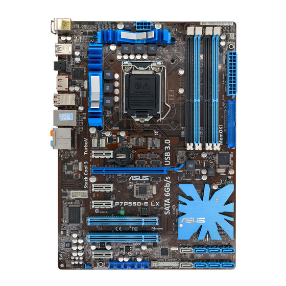
-
Contents
-
Table of Contents
-
Bookmarks
Quick Links
Related Manuals for Asus P7P55D-E LX
Summary of Contents for Asus P7P55D-E LX
-
Page 1
P7P55D-E LX… -
Page 2
Product warranty or service will not be extended if: (1) the product is repaired, modified or altered, unless such repair, modification of alteration is authorized in writing by ASUS; or (2) the serial number of the product is defaced or missing. -
Page 3: Table Of Contents
Contents Contents …………………. iii Notices ………………….vi Safety information ………………vii About this guide ………………viii P7P55D-E LX specifications summary …………. ix Chapter 1: Product introduction Welcome! ………………1-1 Package contents …………….. 1-1 Special features …………….1-1 1.3.1 Product highlights …………1-1 Before you proceed …………..
-
Page 4: Contents
2.1.1 ASUS Update …………..2-1 2.1.2 ASUS EZ Flash 2 …………2-2 2.1.3 ASUS CrashFree BIOS 3 utility ……..2-3 2.1.4 ASUS BIOS Updater …………2-4 BIOS setup program …………..2-7 Entering BIOS Setup at startup …………2-7 Entering BIOS Setup after POST ……….. 2-7 Main menu ………………
-
Page 5
2.7.3 Security …………….. 2-24 Tools menu …………….. 2-25 2.8.1 ASUS O.C. Profile …………2-25 2.8.2 AI NET 2……………. 2-26 2.8.3 ASUS EZ Flash 2 …………2-26 2.8.4 Express Gate …………… 2-26 2.8.5 IO Levelup …………..2-26 Exit menu ………………2-27… -
Page 6: Notices
Complying with the REACH (Registration, Evaluation, Authorisation, and Restriction of Chemicals) regulatory framework, we published the chemical substances in our products at ASUS REACH website at http://green.asus.com/english/REACH.htm. DO NOT throw the motherboard in municipal waste. This product has been designed to enable proper reuse of parts and recycling.
-
Page 7: Safety Information
Safety information Electrical safety • To prevent electrical shock hazard, disconnect the power cable from the electrical outlet before relocating the system. • When adding or removing devices to or from the system, ensure that the power cables for the devices are unplugged before the signal cables are connected. If possible, disconnect all power cables from the existing system before you add a device.
-
Page 8: About This Guide
Refer to the following sources for additional information and for product and software updates. ASUS websites The ASUS website provides updated information on ASUS hardware and software products. Refer to the ASUS contact information. Optional documentation Your product package may include optional documentation, such as warranty flyers, that may have been added by your dealer.
-
Page 9: P7P55D-E Lx Specifications Summary
CPUs. Some hyper DIMMs only support one DIMM per channel. Please refer to Memory QVL for details. ** Refer to www.asus.com or this user manual for the Memory QVL (Qualified Vendors Lists) Expansion Slots 1 x PCI Express 2.0 x 16 slot 4 x PCI Express 2.0 x1 slots (2.5GT/s)
-
Page 10
ASUS Q-LED (DRAM) ASUS Q-Slot ASUS Q-DIMM ASUS Unique Features ASUS IO Level UP for Ultra Performance — True USB 3.0 or True SATA 6Gb/s Support ASUS Xtreme Design ASUS Exclusive Overclocking Features — CPU Level UP, TurboV and Turbo Key… -
Page 11
1 x IO Level UP button BIOS Features 16 Mb Flash ROM, AMI BIOS, PnP, DMI 2.0, WfM 2.0, SM BIOS 2.5, ACPI 2.0a, Multi-language BIOS, ASUS EZ Flash 2, ASUS CrashFree BIOS 3 Manageability WfM 2.0, DMI 2.0, WOL by PME, WOR by PME, PXE… -
Page 13: Chapter 1: Product Introduction
® The motherboard delivers a host of new features and latest technologies, making it another standout in the long line of ASUS quality motherboards! Before you start installing the motherboard, and hardware devices on it, check the items in your package with the list below.
-
Page 14: Before You Proceed
True USB 3.0 Support Experience ultra-fast data transfers at 4.8Gbps with USB 3.0—the latest connectivity standard. Built to connect easily with next generation components and peripherals, USB 3.0 transfers data 10X faster and is also backward compatible with USB 2.0 components. True SATA 6Gb/s Support Supporting next-generation Serial ATA (SATA) storage interface, this motherboard delivers up to 6.0Gb/s data transfer rates.
-
Page 15: Motherboard Layout
(40-1 pin PRI_IDE [Blue]) (4-1 pin SPDIF_OUT) Intel P55 Serial ATA connectors ® 1-23 Standby power LED 1-28 (7-pin SATA 1-6) Marvell Serial ATA 6.0 Gb/s connectors ® 1-26 Serial port connector (10-1 pin COM1) 1-25 (7-pin SATA_6G_1/2 [gray]) ASUS P7P55D-E LX…
-
Page 16: Central Processing Unit (Cpu)
Contact your retailer immediately if the PnP cap is missing, or if you see any damage to the PnP cap/socket contacts/motherboard components. ASUS will shoulder the cost of repair only if the damage is shipment/transit-related. • Keep the cap after installing the motherboard. ASUS will process Return Merchandise Authorization (RMA) requests only if the motherboard comes with the cap on the LGA1156 socket.
-
Page 17
CPU notches. The CPU fits in only one correct orientation. DO NOT force the CPU into the socket to prevent bending Gold the connectors on the socket and triangle damaging the CPU! mark Alignment keys ASUS P7P55D-E LX… -
Page 18
Apply some Thermal Interface Material to the exposed area of the CPU that the heatsink will be in contact with, ensuring that it is spread in an even thin layer. Some heatsinks come with pre-applied thermal paste. If so, skip this step. -
Page 19: Installing The Cpu Heatsink And Fan
Push down two fasteners at a time in a diagonal sequence to secure the heatsink and fan assembly in place. Orient the heatsink and fan assembly such that the CPU fan cable is closest to the CPU fan connector. ASUS P7P55D-E LX…
-
Page 20: Uninstalling The Cpu Heatsink And Fan
Connect the CPU fan cable to the connector on the motherboard labeled CPU_FAN. DO NOT forget to connect the CPU fan connector! Hardware monitoring errors can occur if you fail to plug this connector. 1.6.3 Uninstalling the CPU heatsink and fan To uninstall the CPU heatsink and fan: Disconnect the CPU fan cable from the connector on the motherboard.
-
Page 21: System Memory
The figure illustrates the location of the DDR3 DIMM sockets: Recommended memory configurations One DIMM: Install only one memory module in slot A1 or B1 as a single-channel operation. Two DIMMs (dual-channel operation): Four DIMMs (dual-channel operation): ASUS P7P55D-E LX…
-
Page 22: Memory Configurations
1.7.2 Memory configurations You may install 1GB, 2GB and 4GB unbuffered and non-ECC DDR3 DIMMs into the DIMM sockets. • You may install varying memory sizes in Channel A and Channel B. The system maps the total size of the lower-sized channel for the dual-channel configuration. Any excess memory from the higher-sized channel is then mapped for single-channel operation.
-
Page 23
P7P55D-E LX Motherboard Qualified Vendors Lists (QVL) DDR3-1067MHz capability for CPU at 2.66, 2.8 and 2.93GHz DIMM socket Chip Timing support (Optional) Vendor Part No. Size Chip NO. Voltage Brand Lable(Bios) CORSAIR CM3X1024-1066C7 1024MB DS Heat-Sink Package • • •… -
Page 24
P7P55D-E LX Motherboard Qualified Vendors Lists (QVL) DDR3-1333MHz capability for CPU at 2.66, 2.8 and 2.93GHz (continued) DIMM socket support Timing Vendor Part No. Size DS Chip Brand Chip NO. Voltage (Optional) Dimm(Bios) Crucial CT25672BA1339.18FF 2048MB DS MICRON D9KPT(ECC) 9(1333-9-9-9-24) •… -
Page 25
P7P55D-E LX Motherboard Qualified Vendors Lists (QVL) DDR3-1600MHz capability for CPU at 2.66GHz DIMM socket support Chip Timing Vendor Part No. Size Chip NO. Voltage (Optional) Brand Dimm(Bios) A-DATA AD31600E001GMU 3072MB(Kit of 3) SS N/A Heat-Sink Package 8-8-8-24(1333-9-9-9-24) 1.65-1.85 •… -
Page 26
P7P55D-E LX Motherboard Qualified Vendors Lists (QVL) DDR3-1625MHz capability for CPU at 2.8 and 2.93GHz DIMM socket support SS/DS Chip Timing Vendor Part No. Size Chip NO. Lable(Bios) Voltage (Optional) Brand KINGSTON KHX13000D3LLK2/2GN(EPP) 2048MB(Kit of 2) Heat-Sink Package • •… -
Page 27
P7P55D-E LX Motherboard Qualified Vendors Lists (QVL) DDR3-1866MHz capability for CPU at 2.66GHz DIMM socket support Chip Timing Vendor Part No. Size Brand Chip NO. Voltage (Optional) Dimm(Bios) Apacer 78.0AGCQ.CBZ(XMP) 3GB(Kit of 3) Heat-Sink Package 9-9-9-27(1066-8-8-8-20) • Crucial BL12864BE2009.8SFB3(EPP) Heat-Sink Package 9-9-9-28(1333-9-9-9-24) •… -
Page 28
Hyper DIMM support is subject to the physical characteristics of individual CPUs. • According to Intel spec definition, DDR3-1600 is supported for one DIMM per channel only. ASUS exclusively provides two DDR3-1600 DIMM support for each memory channel. • According to Intel CPU spec, CPUs with a core frequency of 2.66G support the maximum DIMM frequency of up to DDR3-1333. -
Page 29: Expansion Slot
This motherboard has one PCI Express 2.0 x16 slot that supports PCI Express x16 2.0 graphic cards complying with the PCI Express specifications. Refer to section 1-6 Motherboard overview for the location of the expansion slot. ASUS P7P55D-E LX 1-17…
-
Page 30: Jumper
Jumper Clear RTC RAM (3-pin CLRTC) This jumper allows you to clear the Real Time Clock (RTC) RAM in CMOS. You can clear the CMOS memory of date, time, and system setup parameters by erasing the CMOS RTC RAM data. The onboard button cell battery powers the RAM data in CMOS, which include system setup information such as system passwords.
-
Page 31: Onboard Switches
If the installed DIMMs still fail to boot after the whole tuning process, the DRAM_LED lights continuously. Replace the DIMMs with ones recommended in the Memory QVL (Qualified Vendors Lists) in this user manual or on the ASUS website at www.asus.com.
-
Page 32
IO Level UP The IO Level UP switch allows performance boost of the USB 3.0 ports on the rear panel or the onboard SATA 6Gb/s ports. Two LEDs with different colors are provided to indicate different speed mode. Press the IO Level UP switch and restart the system to light up the green (USB3.0) LED. -
Page 33: Connectors
Front Speaker Out Front Speaker Out Pink Mic In Mic In Mic In Mic In Orange – – Center/Subwoofer Center/Subwoofer Black – Rear Speaker Out Rear Speaker Out Rear Speaker Out Gray – – – Side Speaker Out ASUS P7P55D-E LX 1-21…
-
Page 34: Internal Connectors
• Do not forget to connect the 8-pin EATX12V power plug. Otherwise, the system will not boot. • If you are uncertain about the minimum power supply requirement for your system, refer to the Recommended Power Supply Wattage Calculator at http://support.asus. com/PowerSupplyCalculator/PSCalculator.aspx?SLanguage=en-us for details. CPU, chassis, and power fan connectors…
-
Page 35: Serial Ata Connectors
If you installed Serial ATA hard disk drives, you can create a RAID 0, 1, 5, and 10 configuration with the Intel Matrix Storage Technology through the onboard Intel ® ® chipset. ASUS P7P55D-E LX 1-23…
-
Page 36: System Panel Connector
• These connectors are set to Standard IDE mode by default. In Standard IDE mode, you can connect Serial ATA boot/data hard disk drives to these connectors. If you intend to create a Serial ATA RAID set using these connectors, set the Configure SATA as item in the BIOS to [RAID].
-
Page 37
This connector is for a serial (COM) port. Connect the serial port module cable to this connector, then install the module to a slot opening at the back of the system chassis. The COM module is purchased separately. ASUS P7P55D-E LX 1-25… -
Page 38
Digital audio connector (4-1 pin SPDIF_OUT) This connector is for an additional Sony/Philips Digital Interface (S/PDIF) port(s). Connect the S/PDIF Out module cable to this connector, then install the module to a slot opening at the back of the system chassis. The S/PDIF module is purchased separately. -
Page 39
This prevents incorrect insertion when you connect the IDE cable. • Use the 80-conductor IDE cable for Ultra DMA 133/100/66 IDE devices. If any device jumper is set as “Cable-Select”, ensure that all other device jumpers have the same setting. ASUS P7P55D-E LX 1-27… -
Page 40: Onboard Leds
1.11.3 Onboard LEDs POST State LED POST State LED checks DRAM during motherboard booting process. If an error is found , the LED next to the error device will continue lighting until the problem is solved. This user-friendly design provides an intuitive way to locate the root problem within seconds.
-
Page 41: Installing An Operating System
The contents of the support DVD are subject to change at any time without notice. Visit the ASUS website at www.asus.com for updates. 1.13.1 Running the support DVD Place the support DVD into the optical drive.
-
Page 42
1-30 Chapter 1: Product introduction… -
Page 43: Chapter 2: Bios Setup
BIOS in the future. Copy the original motherboard BIOS using the ASUS Update utility. 2.1.1 ASUS Update The ASUS Update is a utility that allows you to manage, save, and update the motherboard BIOS in Windows environment. ®…
-
Page 44: Asus Ez Flash 2
Load Setup Defaults item under the Exit menu. See section 2.9 Exit Menu for details. 2.1.2 ASUS EZ Flash 2 The ASUS EZ Flash 2 feature allows you to update the BIOS without using an OS-based utility. Before you start using this utility, download the latest BIOS file from the ASUS website at www.asus.com.
-
Page 45: Asus Crashfree Bios 3 Utility
The BIOS file in the motherboard support DVD may be older than the BIOS file published on the ASUS official website. If you want to use the newer BIOS file, download the file at support.asus.com and save it to a USB flash drive.
-
Page 46: Asus Bios Updater
Insert the USB flash drive with the latest BIOS file and BIOS Updater to the USB port. Boot your computer. When the ASUS Logo appears, press <F8> to show the BIOS Boot Device Select Menu. Insert the support DVD into the optical drive and select the optical drive as the boot device.
-
Page 47: Backing Up The Current Bios
ASUSTek BIOS Updater for DOS V1.00b [09/06/22] FLASH TYPE: MXIC 25L1605A Current ROM Update ROM BOARD: P7P55D-E LX BOARD: Unknown VER: 0019 VER: Unknown DATE: 12/02/2009 DATE: Unknown PATH: BIOS backup is done! Press any key to continue. Note Saving BIOS: ASUS P7P55D-E LX…
-
Page 48: Updating The Bios File
D:>bupdater /pc /g The BIOS Updater screen appears as below. ASUSTek BIOS Updater for DOS V1.00b [09/06/22] FLASH TYPE: MXIC 25L1605A Current ROM Update ROM BOARD: Unknown BOARD: P7P55D-E LX VER: Unknown VER: 0019 DATE: Unknown DATE: 12/02/2009 PATH: P7P55D.ROM…
-
Page 49: Bios Setup Program
• The BIOS setup screens shown in this section are for reference purposes only, and may not exactly match what you see on your screen. • Visit the ASUS website at www.asus.com to download the latest BIOS file for this motherboard.
-
Page 50: Sata 1-6
2.3.1 SATA 1-6 While entering Setup, the BIOS automatically detects the presence of IDE/SATA devices. There is a separate submenu for each IDE/SATA device. Select a device item then press <Enter> to display the SATA device information. The BIOS automatically detects the values opposite the dimmed items (Device, Vendor, Size, LBA Mode, Block Mode, PIO Mode, Async DMA, Ultra DMA, and SMART monitoring).
-
Page 51: Ahci Configuration
Allows you to set the Self-Monitoring, Analysis and Reporting Technology. Configuration options: [Disabled] [Enabled] 2.3.4 System Information This menu gives you an overview of the general system specifications. The BIOS automatically detects the BIOS information, CPU specification, and system memory in this menu. ASUS P7P55D-E LX…
-
Page 52: Ai Tweaker Menu
Ai Tweaker menu The Ai Tweaker menu items allow you to configure overclocking-related items. Be cautious when changing the settings of the Ai Tweaker menu items. Incorrect field values can cause the system to malfunction. The configuration options for this chapter vary depending on the CPU and DIMM model you installed on the motherboard.
-
Page 53: Ai Overclock Tuner
D.O.C.P. D.O.C.P. • When using DIMMs with a frequncy higher than the Intel CPU spec, use this ASUS ® exclusive DRAM O.C. Profile function to overclock the DRAM. • Adjust BCLK frequency to obtain a better performance after applying the D.O.C.P function.
-
Page 54: Cpu Ratio Setting
2.4.3 CPU Ratio Setting [Auto] Allows you to adjust the ratio between CPU Core Clock and BCLK Frequency. Use the <+> and <-> keys to adjust the value. The valid value ranges differently according to your CPU model. 2.4.4 Intel(R) SpeedStep(TM) Tech [Enabled] When set to [Disabled], the CPU runs at its default speed.
-
Page 55: Dram Timing Control
Configuration options: [Auto] [4 DRAM Clock] [6 DRAM Clock] DRAM WRITE To WRITE Delay (DR) [Auto] Configuration options: [Auto] [2 DRAM Clock] – [9 DRAM Clock] DRAM WRITE To WRITE Delay (SR) [Auto] Configuration options: [Auto] [4 DRAM Clock] [6 DRAM Clock] ASUS P7P55D-E LX 2-13…
-
Page 56: Cpu Differential Amplitude
2.4.10 CPU Differential Amplitude [Auto] Different AMP might enhance BCLK overclocking ability. Configuration options: [Auto] [700mV] [800mV] [900mV] [1000mV] 2.4.11 CPU Clock Skew [Auto] Adjusting this item may help enhancing BCLK overclocking ability. You may need to adjust the CPU Clock Skew item at the same time. Configuration options: [Auto] [Normal] [Delay 100ps]–[Delay 1500ps] Some of the following items are adjusted by typing the desired values using the numeric keypad and press the <Enter>…
-
Page 57: Pch Voltage
Automatic configuration. [Disabled] Enhances the BCLK overclocking ability. [Enabled] Sets to [Enabled] for EMI control. 2.4.19 PCIE Spread Spectrum [Auto] [Auto] Automatic configuration. [Disabled] Enhances the PCIE overclocking ability. [Enabled] Sets to [Enabled] for EMI control. ASUS P7P55D-E LX 2-15…
-
Page 58: Advanced Menu
Advanced menu The Advanced menu items allow you to change the settings for the CPU and other system devices. Be cautious when changing the settings of the Advanced menu items. Incorrect field values can cause the system to malfunction. BIOS SETUP UTILITY Main Ai Tweaker Advanced…
-
Page 59
This item appears only when you set the Intel(R) C-STATE Tech item to [Enabled]. We recommend that you set this item to [Auto] for BIOS to automatically detect the C-State mode supported by your CPU. Configuration options: [Auto] [C1] [C3] [C6] ASUS P7P55D-E LX 2-17… -
Page 60: Uncore Configuration
2.5.2 Uncore Configuration The Uncore Configuration menu allows you to change the advanced chipset settings. Memory Remap Feature [Enabled] [Disabled] Do not allow remapping of memory. [Enabled] Allows for the segment of system memory that was previously overwritten by PCI devices to be remapped above the total physical memory.
-
Page 61: Usb Configuration
[No] When set to [No], BIOS configures all the devices in the system. 2.5.6 Intel VT-d Configuration [Disabled] [Disabled] Disables the Intel Virtualization Technology for Directed I/O. [Enabled] Enables the Intel Virtualization Technology for Directed I/O. ASUS P7P55D-E LX 2-19…
-
Page 62: Power Menu
Power menu The Power menu items allow you to change the settings for the Advanced Power Management (APM). Select an item then press <Enter> to display the configuration options. BIOS SETUP UTILITY Main Ai Tweaker Advanced Power Boot Tools Exit Select the ACPI state Suspend Mode [Auto]…
-
Page 63: Apm Configuration
Power On By PS/2 Mouse [Disabled] [Disabled] Disables the Power On by a PS/2 mouse. [Enabled] Enables the Power On by a PS/2 mouse. This feature requires an ATX power supply that provides at least 1A on the +5VSB lead. ASUS P7P55D-E LX 2-21…
-
Page 64: Hardware Monitor
2.6.7 Hardware Monitor CPU/MB Temperature [xxx�C/xxx�F] [xxx�C/xxx�F] The onboard hardware monitor automatically detects and displays the CPU and motherboard temperatures. Select Ignored if you do not wish to display the detected temperatures. CPU Fan Speed [xxxxRPM] or [Ignored] / [N/A] Chassis Fan 1/2 Speed [xxxxRPM] or [Ignored] / [N/A] Power Fan Speed [xxxxRPM] or [Ignored] / [N/A] The onboard hardware monitor automatically detects and displays the CPU, chassis,…
-
Page 65: Boot Menu
Disables the full screen logo display feature. [Enabled] Enables the full screen logo display feature. Set this item to [Enabled] to use the ASUS MyLogo 2™ feature. AddOn ROM Display Mode [Force BIOS] [Force BIOS] The third-party ROM messages will be forced to display during the boot sequence.
-
Page 66: Security
2.7.3 Security The Security menu items allow you to change the system security settings. Select an item then press <Enter> to display the configuration options. Change Supervisor Password Select this item to set or change the supervisor password. The Supervisor Password item on top of the screen shows the default Not Installed.
-
Page 67: Tools Menu
<Enter> to display the submenu. BIOS SETUP UTILITY Main Ai Tweaker Advanced Power Boot Tools Exit ASUS O.C. Profile AI NET 2 ASUS EZ Flash 2 Express Gate [Auto] Enter OS Timer [10 Seconds] Reset User Data [No] IO Levelup [Disabled] Select Screen ←→…
-
Page 68: Ai Net 2
(POST). 2.8.3 ASUS EZ Flash 2 Allows you to run ASUS EZ Flash 2. When you press <Enter>, a confirmation message appears. Use the left/right arrow key to select between [Yes] or [No], then press <Enter> to confirm your choice.
-
Page 69: Exit Menu
When you select this option or if you press <F5>, a confirmation window appears. Select Ok to load default values. Select Exit & Save Changes or make other changes before saving the values to the non-volatile RAM. ASUS P7P55D-E LX 2-27…
-
Page 70
2-28 Chapter 2: BIOS information…
В представленном списке руководства для конкретной модели Материнской платы — ASUS P7P55D-E Deluxe. Вы можете скачать инструкции к себе на компьютер или просмотреть онлайн на страницах сайта бесплатно или распечатать.
- Инструкции и файлы
- Характеристики
- Основные поломки
- Сервисы по ремонту
В случае если инструкция на русском не полная или нужна дополнительная информация по этому устройству, если вам нужны
дополнительные файлы: драйвера, дополнительное руководство пользователя (производители зачастую для каждого
продукта делают несколько различных документов технической помощи и руководств), свежая версия прошивки, то
вы можете задать вопрос администраторам или всем пользователям сайта, все постараются оперативно отреагировать
на ваш запрос и как можно быстрее помочь. Ваше устройство имеет характеристики:Socket: LGA1156, Поддерживаемые процессоры: Intel Core i7/Core i5, Поддержка многоядерных процессоров: есть, Чипсет: Intel P55, BIOS: AMI c возможностью аварийного восстановления, Поддержка SLI/CrossFire: SLI/CrossFireX, полные характеристики смотрите в следующей вкладке.
Для многих товаров, для работы с ASUS P7P55D-E Deluxe могут понадобиться различные дополнительные файлы: драйвера, патчи, обновления, программы установки. Вы можете скачать онлайн эти файлы для конкретнй модели ASUS P7P55D-E Deluxe или добавить свои для бесплатного скачивания другим посетителями.
Если вы не нашли файлов и документов для этой модели то можете посмотреть интсрукции для похожих товаров и моделей, так как они зачастую отличаются небольшим изменениями и взаимодополняемы.
Обязательно напишите несколько слов о преобретенном вами товаре, чтобы каждый мог ознакомиться с вашим отзывом или вопросом. Проявляйте активность что как можно бльше людей смогли узнать мнение настоящих людей которые уже пользовались ASUS P7P55D-E Deluxe.
Основные и самые важные характеристики модели собраны из надежных источников и по характеристикам можно найти похожие модели.
| Процессор | |
| Socket | LGA1156 |
| Поддерживаемые процессоры | Intel Core i7/Core i5 |
| Поддержка многоядерных процессоров | есть |
| Чипсет | |
| Чипсет | Intel P55 |
| BIOS | AMI c возможностью аварийного восстановления |
| Поддержка SLI/CrossFire | SLI/CrossFireX |
| Память | |
| Память | DDR3 DIMM, 1066 — 2200 МГц |
| Количество слотов памяти | 4 |
| Поддержка двухканального режима | есть |
| Максимальный объем памяти | 16 Гб |
| Дисковые контроллеры | |
| IDE | количество слотов: 1, UltraDMA 133 |
| SATA | количество разъемов SATA 3Gb/s: 7, количество разъемов SATA 6Gb/s: 2, RAID: 0, 1, 5, 10 |
| Слоты расширения | |
| Слоты расширения | 2xPCI-E x16, 3xPCI-E x1, 2xPCI |
| Поддержка PCI Express 2.0 | есть |
| Поддерживаемые режимы PCI-Express | dual: x8 |
| Аудио/видео | |
| Звук | 9.1CH, HDA, на основе VIA VT2020 |
| Сеть | |
| Ethernet | 2×1000 Мбит/с, на основе Realtek 8112L |
| Подключение | |
| Наличие интерфейсов | 14 USB, из них 2 USB 3.0 (2 на задней панели), 2xFireWire (IEEE1394a), выход S/PDIF, 1xCOM, 1xeSATA, 2xEthernet, PS/2 (клавиатура), PS/2 (мышь) |
| Разъемы на задней панели | 8 USB, из них 2 USB 3.0, 1xFireWire (IEEE1394a), коаксиальный выход, оптический выход, 1xeSATA, 2xEthernet, PS/2 (клавиатура), PS/2 (мышь) |
| Основной разъем питания | 24-pin |
| Разъем питания процессора | 8-pin |
| Дополнительные параметры | |
| Форм-фактор | ATX |
| Комплектация | Q-коннекторы,пульт управления TurboV, 1 шлейф IDE, 4 кабеля SATA 3.0 Gb/s, 2 кабеля SATA 6.0 Gb/s, модуль с 2-мя портами USB 2.0 и портом e-SATA, заглушка тыловых портов корпуса, мостик SLI |
| Дополнительная информация | TURBO_CON разъем, кнопка MemOK!, переключатели — Power on , Reset |
Здесь представлен список самых частых и распространенных поломок и неисправностей у Материнских плат. Если у вас такая поломка то вам повезло, это типовая неисправность для ASUS P7P55D-E Deluxe и вы можете задать вопрос о том как ее устранить и вам быстро ответят или же прочитайте в вопросах и ответах ниже.
| Название поломки | Описание поломки | Действие |
|---|---|---|
| Разрыв Печатных Проводников | ||
| Обрыв Конденсаторов Или Резисторов | ||
| Короткое Замыкание В Электрических Цепях | ||
| Разрушение Разъемов И Слотов | ||
| Поломка Процессорного Разъема | ||
| Выгорание Портов | ||
| Микротрещины В Плате | ||
| Выход Из Строя Сетевого Адаптера | ||
| Перегрев Компонентов | ||
| Не Запускается При Включении | При Включении Не Загружается. В Биос Не Входит. Пост Код — А3 | |
| Какой Компонент | Подскажите Марку Траyзистора Q46? | |
| Не Работает Ps/2 | Сначала Отвалилась Клавиатура, А Через Некоторое Время 6 Коротких Гудков И Не Запускается | |
| Подключить Переднюю Панель | Не Могу Подключить Переднюю Панель | |
| Судя По Всему Отвал Биоса | Материнка Стартует Секунд На 5,Кулер Процессора Берет Обороты И Останавливается.и Так-Циклически,Без Остановок.запуск Невозможен.вечером Либо Завтра Буду Пытаться Его Восстановить,Потом Может Дополню | |
| Пропал Звук На Материнке | Пропал Звук На Материнке, Отображается Только Nvidia Hdmi. Переустановка Драйверов С Офсайта Не Помогла. | |
| Биос | При Старте Звук Через Промежетки Времени Примерно В 1-3 Мин Три Сигнала Потом Стартует Винда , Недавно Вообще Написал Cmos Setting Wrong И C7, Жму Del Меняется На B2 Чтоб Воити В Биос Три Сигнала По Одному Через Промеежутки Времени 1-3 Мин И Черный Экра | |
| Asus M2A-Vm Hdmi | Не Запускается Процессор Phenom Ii X4 945 Rev. C3, На Socket-Ам 3, Нет Даже Сигнала, Черный Экран | |
| Не Включается | После Замены Конденсаторов С34 И С35 Не Включается | |
| Черный Экран | Все Уже Перепробовал И Озу Менял И Переставлял И Ластиком Чистил, И Батарейку Вынимал И Измерял, И Видеокарту С Бп На Заведомо Годную Ставил Исход Один, Черный Экран И Speaker Издает 1 Длинный 2 Коротких, Если Я Не Путаю. | |
| Неправильно Отображается Память | При Установленной Памяти 4 Гигабайта В Биосе Отображается 8. Установил Одну Планку 2 Гига — Отображается 4 | |
В нашей базе сейчас зарегестрированно 18 353 сервиса в 513 города России, Беларусии, Казахстана и Украины.

C1 TECHNOLOGY
⭐
⭐
⭐
⭐
⭐
Адресс:
Холодильный пер., д. 3, к. 1
Телефон:
74959552939
Сайт:
n/a
Время работы
Время работы не указано
МАСТЕР КОМП
⭐
⭐
⭐
⭐
⭐
Адресс:
Волгоградский проспект, дом 93, корпус 2
Телефон:
74959892248
Сайт:
n/a
Время работы
Будни: с 1000 до 2000
Суббота: выходной
Воскресенье: выходной
ASUS
⭐
⭐
⭐
⭐
⭐
Адресс:
Старокачаловская улица, д.3 к.2
Телефон:
74999630187
Сайт:
n/a
Время работы
Время работы не указано
ASUS
⭐
⭐
⭐
⭐
⭐
Адресс:
Декабристов, д.10 к.3
Телефон:
74999630187
Сайт:
n/a
Время работы
Время работы не указано
REMOBI
⭐
⭐
⭐
⭐
⭐
Адресс:
Шереметьевская ул., 6, ТЦ Райкин Плаза
Телефон:
74993222524
Сайт:
n/a
Время работы
Ежедневно: с 1000 до 2100
Подводим итоги обзора xeon x3440 на матери asus p7p55d pro
4:46

Очень доволен
хочу
авпваы
Хочу купить
ирлдоьвап ькеьпрлджыкеь дзьакерджь щзрбкежбрь апкыезрбкыеджрбеджр щзапбкерл
Только приобрела,а инструкции нет
Только приобрела,а инструкции нет
Отвалился распрыскиватель
- Инструкции и руководства
- Бренды
- ASUS
- P7P55D-E Premium
- Справочник Пользователя
![]()
Motherboard
P7P55D-E
Premium