
-
Уже зарегистрированы? Войти
-
Регистрация
Информация о файле
Системы ЧПУ для токарных станков OKUMA OSP5020L/OSP500L-G. Паспорт. Содержит описание систем и функций.
Okuma_Manuals_OSP5020L.pdf (31 МБ)
- Manuals
- Brands
- Okuma Manuals
- Control Unit
- OSP-U100M
Manuals and User Guides for Okuma OSP-U100M. We have 1 Okuma OSP-U100M manual available for free PDF download: Operation Manual

www.okuma.de OSP-P300 Простое управление Руководство по управлению OKUMA P300 Training New Generation One Source. First Choice.
 Развитие принципа Простого Управления 2.) Разница между P200 и")
www.okuma.de Перечень описаний: 1.) Развитие принципа Простого Управления 2.) Разница между P200 и P300 2.1) Кнопки управления станком (Пульт управления типа B) 2.1) Ручное управление (Обновленная панель управления) 2.3) Переключение режимов 2.4) Экран управления 2.5) Определение нулевого положения новым способом 2.6) Новый метод работы с инструментом 2.7) Экран регистрации данных инструмента 2.8) Ручные операции при работе с магазином инструментов New Generation One Source. First Choice.
 Как регистрировать данные инструмента 4.) Процесс расточки сырых кулачков 5.)")
www.okuma.de Перечень описаний: 3.) Как регистрировать данные инструмента 4.) Процесс расточки сырых кулачков 5.) Совместимость с командами TL стойки P200 6.) OSP-P300 Перечень инструкций New Generation One Source. First Choice.
 OSP-P300S Принципы простого управления -")
www.okuma.de New Generation One Source. First Choice. 1.) OSP-P300S Принципы простого управления — Гладкое управление, без потери направления — Функция комплексного использования, без потери направления для опытных и начинающих операторов. (Стратегия выполнения) — “Управление на одном экран” Это все составляющие обслуживания и работы на одном экране — Совокупные данные описания инструмента для контура, позиции, направления резания, и вылетов для каждого инструмента списка Совместимые данные для инструмента между каталогом данных магазина, OneTouch-IGF иCAS — Расширение функций ручного управления — Новая панель управления для контроля за обработкой, без потери направления
 Различия между стойкой P200 и")
www.okuma.de New Generation One Source. First Choice. 2.1 ) Различия между стойкой P200 и стойкой P300 — Новая панель управления (для многофункциональных станков) Инструмент установка/удаление Кнопки переключения Кнопки управления перемещениями Кнопки управления ЧПУ Кнопки управления станком Управление и переключение шпинделей Управляемые объекты, смена и переключение Включение, выключение

www.okuma.de New Generation One Source. First Choice. Дополнительные функции OSP дисплея
 Ручное управление (новая панель управления)")
www.okuma.de New Generation One Source. First Choice. 2.2) Ручное управление (новая панель управления) — Ручное управление Возможно! Просто нажмите новую кнопку управления! — В стойке P200, было необходимо использовать режим Ручного ввода данных Поворотный переключатель может быть установлен в позицию позиционирования инструментального шпинделя. Позиционирование 45 градусов так же возможен! Позиция переключения: Лимит (положительный) по оси Х

www.okuma.de New Generation One Source. First Choice. Подключение оси C возможно нажатием кнопки При подключении ось C возвращается в нулевое положение В стойке P200, только по коду M функции M110/M109 (Примечание) При включении приводов, до позиционирования в необходимую точку, заблокируйте дверь, затем, нажатием кнопки, перейдите в нулевое положение Инструмент занимает требуемую позицию при нажатии кнопки Удобно при необходимости смены режущих пластин В стойке P200, только по коду M функции M602/M603 Позиция переключения: Лимит (положительный) по оси Х, заблокированная дверь

www.okuma.de New Generation One Source. First Choice. Аналоговый поворотный переключатель, изменяющий скорость вращения шпинделя. Возможно регулировать с большой точностью во время резания. E100 — > Аналоговый поворотный переключатель P200 — > Цифровой переключатель P300 — > Аналоговый поворотный переключатель [включение режима оси Y] . [возврат режима оси Y] Возможно по нажатию кнопки. Для стойки P200 по M коду G138
![>www.okuma.de New Generation One Source. First Choice. [Зажим шпинделя] возможен по нажатию кнопки При](https://present5.com/presentacii-2/20171208/14668-p300_training_rus.ppt/14668-p300_training_rus_10.jpg ">www.okuma.de New Generation One Source. First Choice. [Зажим шпинделя] возможен по нажатию кнопки При")
www.okuma.de New Generation One Source. First Choice. [Зажим шпинделя] возможен по нажатию кнопки При выполнении наладки станка на обработку иногда необходимо фиксироватьглавный шпиндель Для стойки P200 , только по M коду M146 Отключение блокировки шпинделя M147 Включение блокировки шпинделя (Появляется ошибка при нажатии этой кнопки без активации оси С) [Ориентация шпинделя] возможна по нажатию кнопки. Для стойки P200 , только по M коду M19 Ориентация шпинделя.

www.okuma.de New Generation One Source. First Choice. Изменен цвет кнопок. Красный цвет означает “Операции остановки ” (прерывания) Голубой цвет означает “ Изменение режима”

www.okuma.de New Generation One Source. First Choice. Кнопка Операций обработки Кнопка управления дополнительными функциями станка, отображается на одном экране. P300 P200 Датчик привязки, Измерения при обработке, Охлаждение, Обдув воздухом, Монитор нагрузки, Операции с магазином и другие дополнительные функции могут управляться этими функциональными кнопками. Только по нажатию кнопки дисплея./ Темно серый цвет означает, что функция не включена в спецификацию станка.
![>www.okuma.de New Generation One Source. First Choice. 2.3) Переключение и выбор режимов [Рабочий дисплей]](https://present5.com/presentacii-2/20171208/14668-p300_training_rus.ppt/14668-p300_training_rus_13.jpg ">www.okuma.de New Generation One Source. First Choice. 2.3) Переключение и выбор режимов [Рабочий дисплей]")
www.okuma.de New Generation One Source. First Choice. 2.3) Переключение и выбор режимов [Рабочий дисплей] —> новая кнопка [Опреедление нулевого положения] —>Перешла из кнопки режимов в «рабочий дисплей» Больше нет отдельной кнопки для режима определения нулевого положения

www.okuma.de New Generation One Source. First Choice. — > Move to Run screen (Spindle setup) Кнопки выбора режимов управления Кнопки выбора режимов установки данных Для выражения функционального различия, был изменен цвет кнопок
 Рабочий дисплей Управление процессом обработки можно")
www.okuma.de New Generation One Source. First Choice. 2.4) Рабочий дисплей Управление процессом обработки можно выполнять без смены рабочих дисплеев, Это называется Единый экран управления (Рабочий дисплей, в отличии от стойки P200)

www.okuma.de New Generation One Source. First Choice. Управление процессом обработки можно выполнять без смены рабочих дисплеев, Это называется Единый экран управления (Рабочий дисплей, в отличии от стойки P200) Рабочий дисплей
![>www.okuma.de New Generation One Source. First Choice. При нажатии [Рабочий экран] появляется следующий экран.](https://present5.com/presentacii-2/20171208/14668-p300_training_rus.ppt/14668-p300_training_rus_17.jpg ">www.okuma.de New Generation One Source. First Choice. При нажатии [Рабочий экран] появляется следующий экран.")
www.okuma.de New Generation One Source. First Choice. При нажатии [Рабочий экран] появляется следующий экран. Индикатор индивидуальных лимитов Зеленый : + лимит Красный : — лимит Статусная строка Режим осей C/Y ( убрана ) ATC статус (новое) Индикатор нагрузки Дисплей активных номеров корректоров ( Текущая позиция ) закладка Рабочий дисплей

www.okuma.de New Generation One Source. First Choice. Количество закладок зависит от спецификации станка. Двухшпиндельная спецификация 3 Закладки [Действительная позиция][1шпиндель установка][2 шпиндель установка] Спецификация с задней бабкой 3 Закладки [Действительная позиция][шпиндель установка][задняя бабка] Стандартная спецификация 2 Закладки [Действительная позиция][шпиндель установка] Рабочий дисплей
 Определение кулачков Определение")
www.okuma.de New Generation One Source. First Choice. (Закладка установки шпинделя) Определение кулачков Определение Заготовки Установка нуля детали Изображение Действительная позиция Вызываются данные с ключевыми символами[Вводные параметры безопасности] Эти данные не могут быть изменены в режиме управления. Для ввода данных нажмите кнопку [F1](SET), введите данные, Затем нажмите [WRITE]. Эти данные без ключевой маркировки можно ввести напрямую без [F1]Set. (DIRECT INPUT) Рабочий дисплей
 Установка нового нулевого положения (Системный параметр)")
www.okuma.de New Generation One Source. First Choice. 2.5) Установка нового нулевого положения (Системный параметр) Определение машинного нуля Spindle nose =0 ( Расстояние до машинного нуля за пределами станка.) ( Дисплей управления ) Нулевое положение Ширина патрона + Высота кулачков + Вылет заготовки (Установка пользователем)

www.okuma.de New Generation One Source. First Choice. Установка нового нуля детали

www.okuma.de New Generation One Source. First Choice. Установка нового нулевого положения

www.okuma.de New Generation One Source. First Choice. P300 P200 Кнопка привязки нуля доступна на панели режимов, (Машинные координаты) Абсолютные данные от установленного нуля энкодера, не используется для другого станка. [Установка нуля /Смещение нуля] Перемещается в режиме установки данных шпинделя. Торец конца шпинделя это нулевая точка станка, смещение нулевого положения это [ширина патрона]+ [высота кулачков] + [вылет детали] (это зависит от заказчика) Установка нового нулевого положения Различие процедуры установки нуля между стойками P200 и P300
 Новый метод установки данных инструмента")
www.okuma.de New Generation One Source. First Choice. 2.6) Новый метод установки данных инструмента Нажмите кнопку TOOL DATA установка данных инструмента, следующий экран появится. Имеются 3 закладки(Информация о магазине/Данные инструмента /Контроль за сроком службы инструмента) Для переключения закладки просто нажмите: Или нажмите кнопки переключения закладок на операционной панели. [Закладка Информация о магазине] Все параметры магазина можно проверить на экране этой закладки

www.okuma.de New Generation One Source. First Choice. Новый метод установки данных инструмента (Закладка данных инструмента) Все данные инструмента могут быть проверены в этом режиме

www.okuma.de New Generation One Source. First Choice. Закладка Tool life time management Новый метод установки данных инструмента
Кнопка управления операциями (Панель управления типа В)")
www.okuma.de New Generation One Source. First Choice. 2.6)Кнопка управления операциями (Панель управления типа В) Нет задержек и потери времени для начинающих операторов, все режимы собраны в одном месте. Расширены возможности ручного управления. P300 Кнопка управления операциями (P200 : тип-B на панели управления) Датчик привязки, Измерения в процессе обработки, Охлаждение, Обдув воздухом, Монитор нагрузки, Магазин инструментов, Основными дополнительными функциями возможно управлять при помощи этого дисплея. Просто выберите и дотроньтесь до иконки, тогда дисплей изменится Иконки серого цвета означают [эта спецификация не активна для этого станка]
![>www.okuma.de Операции ручной работы с магазином возможны в режиме [Операции управления] и [Установка](https://present5.com/presentacii-2/20171208/14668-p300_training_rus.ppt/14668-p300_training_rus_28.jpg ">www.okuma.de Операции ручной работы с магазином возможны в режиме [Операции управления] и [Установка")
www.okuma.de Операции ручной работы с магазином возможны в режиме [Операции управления] и [Установка данных инструмента]. (В режиме Операций управления ) Используется для работы. Метод управления такой же как и на стойке P200. Нажмите кнопку ручной работы с магазином, появится меню ручной работы с магазином. Одношаговое управление, возможен один цикл управления. Из этого режима выполнять управление простыми циклами возможно находясь не в позиции смены Перемещая позицию шпинделя инструмента вы должны следить что бы дверь станка была закрыта и заблокирована. 2.7) Операции ручной работы с магазином New Generation One Source. First Choice.
![>(В режиме установки данных инструмента) В режиме регистрации инструмента, Нажмите[F6] (Ручная смена инструмента), по](https://present5.com/presentacii-2/20171208/14668-p300_training_rus.ppt/14668-p300_training_rus_29.jpg ">(В режиме установки данных инструмента) В режиме регистрации инструмента, Нажмите[F6] (Ручная смена инструмента), по")
(В режиме установки данных инструмента) В режиме регистрации инструмента, Нажмите[F6] (Ручная смена инструмента), по нажатию Появляется экран управления магазином. Положение станка [Дверь закрыта и заблокирована] и [ось Х положительный лимит] Нет необходимости подключать режим работы с осью Y! Нет необходимости выполнять команды движения шпинделя! ①Выберете закладку Информация магазина или установка данных инструмента ②Выберете номер инструмента, который надо заменить касанием дисплея ③Нажмите F6 (Ручная смена инструмента), Меню работы с магазином появится. www.okuma.de New Generation One Source. First Choice. Выбранный номер инструмента возможно переместить. В верхний левый угол. Кнопки окрашены в зеленый цвет [F1] . Если вы выбрали инструмент, которого нет в магазине, выполнить смену невозможно. Нажатие кнопки [F1] смена инструмента, шпиндель переместится в позицию смены автоматически. После этого начнется процедура смены инструмента.
Номера позиций инструмента ( Новая команда для")
www.okuma.de New Generation One Source. First Choice. 2.8)Номера позиций инструмента ( Новая команда для работы с инструментом команда TD) Команда подготовки инструмента [Подготовка следующего инструмента Смена инструмента Позиционирование Включение корректоров] Только команда TD Подготовка следующего инструмента Смена инструмента Позиционирование по оси В Поворот по команде М602 Включение корректора (корректор 2)
![>www.okuma.de New Generation One Source. First Choice. Новый принцип работы [Позиция инструмента] используется в](https://present5.com/presentacii-2/20171208/14668-p300_training_rus.ppt/14668-p300_training_rus_31.jpg ">www.okuma.de New Generation One Source. First Choice. Новый принцип работы [Позиция инструмента] используется в")
www.okuma.de New Generation One Source. First Choice. Новый принцип работы [Позиция инструмента] используется в стойке P300. Для каждого номера инструмента возможно регистрировать 20 позиций. Для стойки P200, взаимодействие между номером инструмента и корректором выполнялось по команде TL. Индексация шпинделя(BA / BT) и инструмента(M602/M603) должна выполнятся каждый раз. (Новая команда для работы с инструментом команда TD) Формат команды TD TD=△△○○○○ M423 △ △ = Номер позиции No. (1~20) ○○○○ = Инструмент No. (9999) Позиции No. 1 — 6 для главного шпинделя(FIX) Позиции No. 7 — 11 для противошпинделя(FIX) Позиции No.13 — 20для свободного использования
 Как создать данные модели (функция")
www.okuma.de New Generation One Source. First Choice. 3. ) Как создать данные модели (функция Easy Modeling) Для проверки столкновений в системе CAS , Существует регистрация данных модели. Базовая модель станка( ex H1 инструментальный шпиндель шпиндель) подготовлена OKUMA. Но данные модели [патрона] / [кулачков] / [заготовки] / [инструмента] / [державок] должны быть созданы отдельно
")
www.okuma.de New Generation One Source. First Choice. Как создавать данные моделей (Easy Modeling) Контур обработки (рабочий дисплей) Установка данных инструмента Контур обработки (Простое моделирование) Патрон Кулачки Заготовка Инструмент Державка
")
www.okuma.de New Generation One Source. First Choice. Как создавать данные моделей (Easy Modeling) Контур обработки (Простое моделирование) [Контур обработки] означает установку параметров моделей Патрона/Кулачков/Заготовки. Существуют 2 пути для создания данных моделей. [Рабочий дисплей (установка параметров шпинделя] или [Простое моделирование]

www.okuma.de New Generation One Source. First Choice. ①Контур обработки из режима Рабочий дисплей (Установка данных шпинделя)

www.okuma.de New Generation One Source. First Choice. ② Контур обработки с помощью функции Easy modeling ( Ожидаемые действия) Действительная проверка на столкновения Сложный контур патрона Сложный контур кулачков Сложный контур заготовки

www.okuma.de New Generation One Source. First Choice. 【Как начать процесс установки контура/Простое моделирование】 Контур процесса из рабочего дисплея Контур процесса с помощью функции EASY MODELING

www.okuma.de New Generation One Source. First Choice. 【 Как начать процесс установки контура/Простое моделирование 】

www.okuma.de New Generation One Source. First Choice. Установка позиции заготовки в кулачках

www.okuma.de New Generation One Source. First Choice. 【Контур процесса из Рабочего дисплея】 При изменении параметров установки, пожалуйста нажмите [F6] (Редактирование параметров) В другом случае таблица параметров серая и не доступна для редактирования!

www.okuma.de New Generation One Source. First Choice. 【 Контур процесса из Рабочего дисплея 】 Введите все необходимые параметры.

www.okuma.de New Generation One Source. First Choice. 【 Контур процесса из Рабочего дисплея 】

www.okuma.de New Generation One Source. First Choice. 【F4 Установка параметров патрона】 Введите размер кулачков

www.okuma.de New Generation One Source. First Choice. 【 F5 Установка вылета заготовки в кулачках】
![>www.okuma.de New Generation One Source. First Choice. Выберите [Yes], потом запустите импорт информации о](https://present5.com/presentacii-2/20171208/14668-p300_training_rus.ppt/14668-p300_training_rus_45.jpg ">www.okuma.de New Generation One Source. First Choice. Выберите [Yes], потом запустите импорт информации о")
www.okuma.de New Generation One Source. First Choice. Выберите [Yes], потом запустите импорт информации о модели в CAS. После передачи данных, проверьте данные на мониторе CAS Установка вылета заготовки в кулачках

www.okuma.de New Generation One Source. First Choice. Установка вылета заготовки в кулачках Примечание 1: Если установлен неверный параметр для создания параметров модели, появляется сообщение об ошибке, [ошибка при создании моделей] В этом случае ошибка появляется потому что L2 длиннее чем L1

www.okuma.de New Generation One Source. First Choice. Примечание 2: Как удалить данные из рабочего дисплея (Установка данных шпинделя) Измените ID данные от значения[EMPTY] до [None] — >Нажмите F2 [Выберите NONE] Установка вылета заготовки в кулачках

www.okuma.de New Generation One Source. First Choice. Установка вылета заготовки в кулачках Примечание 3: Файл данных установки ( расширение DDT) Параметры установленные в режиме Рабочий дисплей (spindle set up ) возможно сохранять в файле. Этот файл данных имеет расширение [DDT (DANDORI DATA FILE)] Пожалуйста введите имя файла, потом нажмите OK. DDT файл будет сохранен в редакторе MD1: Удобно использовать то же имя файла что и имя программы ЧПУ.

www.okuma.de New Generation One Source. First Choice. Есть возможность читать данные DDT файла нажатием F6 [установка чтение] DDT файл будет сохранен в каталоге MD1:. Проверьте файл управляющей программы. Файл с тем же именем но другим расширением [CSV]так же будет создан автоматически. Это промежуточный файл, пожалуйста игнорируйте его (но не удаляйте)
.")
www.okuma.de New Generation One Source. First Choice. DDT файл это файл текстового формата (XML). Его возможно читать и редактировать. Extensible Markup Language (XML) это установленные правила для кодирования документов в формате читаемом машиной machine-readable.
![>www.okuma.de New Generation One Source. First Choice. [Создание данных модели из редактора Easy Modeling]](https://present5.com/presentacii-2/20171208/14668-p300_training_rus.ppt/14668-p300_training_rus_51.jpg ">www.okuma.de New Generation One Source. First Choice. [Создание данных модели из редактора Easy Modeling]")
www.okuma.de New Generation One Source. First Choice. [Создание данных модели из редактора Easy Modeling] Как запустить «easy modeling». Для некоторых целей, изменен метод старта. A)Подготовка до обработки / только работа с файлами моделей ⇒ Пожалуйста запускайте с вертикальной панели кнопок, (Возможно в любое время) B)Установка кулачков и заготовки ⇒ Рабочий дисплей (установка данных шпинделя)/ контур обработки (параметры) От задания данных до загрузки модели CAS. C)Инструмент/ Державка, регистрация и установка ⇒ Режим установки данных Tool data setting mode От задания данных до загрузки модели CAS.
![>www.okuma.de New Generation One Source. First Choice. [Создание данных модели из редактора Easy Modeling]](https://present5.com/presentacii-2/20171208/14668-p300_training_rus.ppt/14668-p300_training_rus_52.jpg ">www.okuma.de New Generation One Source. First Choice. [Создание данных модели из редактора Easy Modeling]")
www.okuma.de New Generation One Source. First Choice. [Создание данных модели из редактора Easy Modeling] 2 way of start easy modeling Есть два пути для запуска функции простого моделирования «easy modeling». 1.) Нажатием кнопки на вертикальном функциональном дисплее 2.) Нажатием [ F1 ](В режиме определения контура обработки) 1.) Нажатием кнопки на вертикальном функциональном дисплее
![>www.okuma.de New Generation One Source. First Choice. [Создание данных модели из редактора Easy Modeling]](https://present5.com/presentacii-2/20171208/14668-p300_training_rus.ppt/14668-p300_training_rus_53.jpg ">www.okuma.de New Generation One Source. First Choice. [Создание данных модели из редактора Easy Modeling]")
www.okuma.de New Generation One Source. First Choice. [Создание данных модели из редактора Easy Modeling] Функция Easy modeling простое моделирование служит для: — [Инструмент] [Державка] [Заготовка] [Кулачки] [Патрон] Данные для каждой модели можно сохранить отдельным файлом. Создание новых данных, перемещение, переименование так же возможно. Так же как в системе CAS на стойке P200 Данные модели заготовки Данные модели фиксаторов Данные модели инструментов Данные модели державок
![>www.okuma.de New Generation One Source. First Choice. [Создание данных модели из редактора Easy Modeling]](https://present5.com/presentacii-2/20171208/14668-p300_training_rus.ppt/14668-p300_training_rus_54.jpg ">www.okuma.de New Generation One Source. First Choice. [Создание данных модели из редактора Easy Modeling]")
www.okuma.de New Generation One Source. First Choice. [Создание данных модели из редактора Easy Modeling] Все данные моделей для патрона, кулачков, и заготовки можно сохранить индивидуально. Эти файлы возможно использовать [ID Select] Из Рабочего дисплея (Установка шпинделя) Патрон Кулачки Заготовка
 Как регистрировать данные инструмента Философия")
www.okuma.de New Generation One Source. First Choice. 3.) Как регистрировать данные инструмента Философия новой стойки Р300 это совмещение всей информации на одном экране. Поэтому все данные для инструмента можно использовать в системах CAS и IGF после окончания полной регистрации. Дисплей данных инструмента разделен на три закладки. Информация о магазине, здесь отображаются инструменты, которые установленны в магазине. Данные инструмента (Все), Здесь отображаются все инструменты, зарегистрированные на стойке станка. Контроль за сроком службы инструмента

www.okuma.de New Generation One Source. First Choice. Информация о магазине Magazine Info
 Tool Life Manag.")
www.okuma.de New Generation One Source. First Choice. Данные инструмента (все ) Tool Life Manag. Tool List. P200

www.okuma.de New Generation One Source. First Choice. Контроль за сроком службы инструмента
")
www.okuma.de New Generation One Source. First Choice. Существуют 2 пути регистрации инструмента. 1.) Регистрация инструмента и установка в магазин (TOOL register and attach) (из таблицы информации о магазине) 2.) Регистрация данных об инструменте (Register tool data) (from TOOL DATA tab) Как регистрировать данные инструмента Процедура: — Установите инструмент в инструментальный шпиндель. 1.) Регистрация инструмента и установка в магазин (TOOL register and attach)

www.okuma.de New Generation One Source. First Choice. Как регистрировать данные инструмента Процедура: Выберите кнопку «Tool REG&ATT»

www.okuma.de New Generation One Source. First Choice. Как регистрировать данные инструмента Процедура: Введите значения: Номер инструмента: i.e. 100 Каментарий: i.e. ID Rough Тип инструмента: Turning (выбирается из предложенного меню) Размер инструмента: Standard (выбирается из предложенного меню.) Базовая позиция: Здесь указывается фиксированная позиция в котором проводим измерение инструмента по датчику.

www.okuma.de New Generation One Source. First Choice. Как регистрировать данные инструмента Базовая позиция: В базовом прилагающемся меню двенадцать зафиксированных позиций. Оператор может выбрать здесь необходимую позицию. Для левого и правого шпинделя.

www.okuma.de New Generation One Source. First Choice. Как регистрировать данные инструмента Базовая позиция: Используйте кнопку “Curt.Pos reading” [ F4 ] Чтение базовой позиции. Эта кнопка позволяет считать действительное положение инструментального шпинделя, и его положение относительно оси (M602/M603) прямо со станка (текущего положения). Функция считывания текущей позиции. Угол H1 револьверной головки. BA=0 BA=45 BA=90 или произвольный угол M индексированная позиция M602/M603 0 градусов или 180 градусов
![>www.okuma.de New Generation One Source. First Choice. Как регистрировать данные инструмента [Считывание действительной позиции]](https://present5.com/presentacii-2/20171208/14668-p300_training_rus.ppt/14668-p300_training_rus_64.jpg ">www.okuma.de New Generation One Source. First Choice. Как регистрировать данные инструмента [Считывание действительной позиции]")
www.okuma.de New Generation One Source. First Choice. Как регистрировать данные инструмента [Считывание действительной позиции] — > Проверьте действительное положение инструментального шпинделя, затем регистрируйте данные инструмента. Вспомогательная картинка: положения 1 – 12 фиксированные (выбраны OKUMA) 13- 20 свободные позиции могут использоваться по необходимости

www.okuma.de New Generation One Source. First Choice. Процедура: Выберите режим привязки по датчику Touch setter. Определите вылеты инструмента по датчику (процедура аналогична P200 стойке) Как регистрировать данные инструмента

www.okuma.de New Generation One Source. First Choice. Процедура: Следующим щагом регистрируем данные для системы CAS. Возможно пропустить эту установку! Примечание: Данные моделей для CAS являются приоритетной информацией по инструменту для системы IGF. Поэтому установки для CAS иногда можно не выполнять, в этом случае в системе IGF не будет доступных приоритетных инструментов! Как регистрировать данные инструмента

www.okuma.de New Generation One Source. First Choice. Как регистрировать данные инструмента Процедура: Нажмите кнопку “Select Holder” [ F1] Выберите модель державки из библиотеки

www.okuma.de New Generation One Source. First Choice. Процедура: Нажмите кнопку “Select Tool” [ F2] Выберите модель инструмента из библиотеки Как регистрировать данные инструмента

www.okuma.de New Generation One Source. First Choice. Как регистрировать данные инструмента Процедура: Настройте действительный вылет модели инструмента используя кнопку “ Change Setting” [ F4 ].

www.okuma.de New Generation One Source. First Choice. Как регистрировать данные инструмента Процедура: Настройте вылет инструмента используя кнопку “ Auto Set” [ F4 ]. Завершите установку, выберите “ OK “ и “ OK “ снова.

www.okuma.de New Generation One Source. First Choice. Как регистрировать данные инструмента Данные вылета инструмента Графические данные инструмента Перечень инструмента для IGF

www.okuma.de New Generation One Source. First Choice. TOOL List in use Для примера, Согласно спецификации станок имеет 60 позиций, зарегистрированного инструмента на станке больше 100 позиций. Фактически не возможно установить весь зарегистрированный инструмент в магазин. Это означает что у нас есть перечень инструмента объемом более 100 позиций ( Tool Data ALL ) и магазин, в который мы можем поставить 60 инструментов ( Magazine Info). Для получения точного представления какой инструмент установлен в магазине а какой только зарегистрирован (или не зарегистрирован) Okuma представляет функцию “TOOL LIST in USE”. Когда управляющая программа выбрана, функция «TOOL LIST in USE» сканирует программу, что бы выявить какой инструмент используется в программе.

www.okuma.de New Generation One Source. First Choice. TOOL List on use Режим Автомат AUTO — > F1 (Выбор программы) Нажмите F5 (Смена вылетов OFFSET CHANGE)

www.okuma.de New Generation One Source. First Choice. TOOL List on use TOOL LIST in use работает при выбранной NC программе Появляется перечень используемого инструмента. Цель этого перечня быстрое изменение данных инструмента в режиме Рабочего дисплея. Пустая линия означает, что данных об инструменте нет в базе данных стойки Возможно данные есть в перечне неустановленного инструмента или инструмент еще не зарегистрирован.

www.okuma.de New Generation One Source. First Choice. Экран отсутствующего инструмента Режим установки данных инструмента — > Закладка информации магазина — >F3 Lack Tool list

www.okuma.de New Generation One Source. First Choice. Экран отсутствующего инструмента После использования Lack Tool List, в правом окошке отобразятся недостающие инструменты.
")
www.okuma.de New Generation One Source. First Choice. Функция сохранения данных инструмента(Tool data IN/OUT function) На новой стойке P300 есть возможность сохранить все зарегистрированные инструменты. Этот файл данных составлен только на основе данных NC программы, Данные моделей CAS не включены. Если вы используете эти данные для другого станка, пожалуйста проверьте данные моделей для инструмента и державок. Режим установки данных инструмента— > Закладка TOOL DATA— >Установите курсор на список инструмента. Затем нажмите ▲ F3【TOOL DATA INPUT】 F4【TOOL DATA OUTPUT】 отобразятся

www.okuma.de New Generation One Source. First Choice. Примечание: Если курсор на позиции определения вылета инструмента. Функция Ввод/Вывод не появляется в функциональных кнопках. Функция сохранения данных инструмента Нажмите F4【TOOL data out put】

www.okuma.de New Generation One Source. First Choice. Функция сохранения данных инструмента Выберите местоположение файла и имя папки

www.okuma.de New Generation One Source. First Choice. Нажмите OK, затем появится диалоговое окно Нажмите [F6] и начнется процесс формирования данных. Функция сохранения данных инструмента Каждый номер инструмента имеет свой файл индивидуально. Возможно копирование этих файлов на USB носитель.

Если номер инструмента уже имеется на стойке OSP, появляется значок на перечне. Есть возможность использовать эти файлыс данными на других станках. www.okuma.de New Generation One Source. First Choice. Функция сохранения данных инструмента F3 [TOOL DATA INPUT] Есть возможность ввести данные из сохраненного файла в стойку OSP Выберите папку с данными F1 После выбора папки с данными, OSP сканирует эти файлы автоматическиthese, а затем создает список инструмента.
 Обработка сырых кулачков без программирования 【Рабочий")
www.okuma.de New Generation One Source. First Choice. 4.) Обработка сырых кулачков без программирования 【Рабочий дисплей RUN DISPLAY】→【F4 SOFTJAW PROCESS】

www.okuma.de New Generation One Source. First Choice. Появляется следующий дисплей. Выберите Rough TOOL CELL — >нажмите F3 (SOFT JAW TOOL SET) Обработка сырых кулачков без программирования
![>www.okuma.de New Generation One Source. First Choice. После выбора [F3] Soft jaw Tool-Set, на](https://present5.com/presentacii-2/20171208/14668-p300_training_rus.ppt/14668-p300_training_rus_84.jpg ">www.okuma.de New Generation One Source. First Choice. После выбора [F3] Soft jaw Tool-Set, на")
www.okuma.de New Generation One Source. First Choice. После выбора [F3] Soft jaw Tool-Set, на дисплее появляется список инструмента. Выберите подходящий инструмент и нажмите “OK”, такая же процедура для чистового точения. Обработка сырых кулачков без программирования

www.okuma.de New Generation One Source. First Choice. Обработка сырых кулачков без программирования Укажите данные контура сырых кулачков. После указания всех данных нажмите F1 (Подготовка старта обработки Prepare Start)

www.okuma.de New Generation One Source. First Choice. Обработка сырых кулачков без программирования Пожалуйста согласуйте с CAS указанные данные. Свойства модели будут изменены с зеленого на серый цвет. Для предотвращения столкновений. После проточки кулачков данные модели будут обновлены согласно полученному контуру. После окончания подготовки старта, NC программа будет показана в левой части окна. Эта программа не может быть сохранена и отредактирована.

www.okuma.de New Generation One Source. First Choice. Обработка сырых кулачков без программирования Переключите режим на Автомат, Затем нажмите cycle start! После окончания обработки нажмите F7 После этого данные кулачков в модели обновятся

www.okuma.de New Generation One Source. First Choice. Обработка сырых кулачков без программирования Параметры кулачков так же обновятся и будут аналогичны параметрам установки SOFTJAW PROCESS.

www.okuma.de New Generation One Source. First Choice. Обработка сырых кулачков без программирования Пожалуйста выберите дисплей системы CAS, контур кулачков должен быть изменен. В этот момент, данные модели кулачков изменят свойства. Цвет модели изменится обратно с серого на зеленый. Модель кулачков более не являются заготовкой.
 Совместимость команд TL и TD Самое")
www.okuma.de New Generation One Source. First Choice. 5.) Совместимость команд TL и TD Самое большое различие между стойками P300 и P200 это работа с инструментом и команды для позиционирования. При этом взаимосвязь между стойками потеряна, это означает что существующие NC программы со стойки P200 не подходят для использования на стойке P300. Okuma развивает новые функции, которые позволяют использовать старый ISO код программ. Использование параметров позволяет переключать режимы TD ( P300 ) или TL ( P200 ) Этот параметр не приоритетный и не глобальный. Примечание: Если станок переключен в режим TL, все равно нет возможности создавать NC программы при помощи IGF в кодах TL команд.

www.okuma.de New Generation One Source. First Choice. Как переключить режим TL: OPTIONAL PARAMETER Совместимость команд TL и TD

www.okuma.de New Generation One Source. First Choice. Совместимость команд TL и TD Статусный индикатор STATUS INDICATOR в режиме TD.

www.okuma.de New Generation One Source. First Choice. Совместимость команд TL и TD Статусный индикатор STATUS INDICATOR В режиме TL.

www.okuma.de New Generation One Source. First Choice. Совместимость команд TL и TD Если активен TL режим Режим установки данных инструмента минимизирован только для ввода: Позиция инструмента Тип инструмента Размер инструмента Номер корректора и инструмента зафиксирован в NC программе В режиме TL – P300 используется тот же экран для корректоров что и для стойки P200.

www.okuma.de New Generation One Source. First Choice. Совместимость команд TL и TD Управление производится так же как в кодах TL команды — Измените параметр на режим TL — Выберите NC программу с командами TL — После полного выбора программы, After completing the program selection, «Пожалуйста проверьте регистрацию инструмента, которая использует установленные данные инструмента». выберите [CHECK] или [CHECKED]

www.okuma.de New Generation One Source. First Choice. Совместимость команд TL и TD Измените экран на экран данных инструмента. Нажмите F5 (Программный перечень инструмента, Program tool list ) Эта функция сканирует всю программу для определения какой инструмент используется, в какой позиции и под каким углом позиционирования. В итоге на экране появляется итоговый перечень инструмента.

www.okuma.de New Generation One Source. First Choice. Совместимость команд TL и TD Перечень инструмента программы отображается в отдельном окне Пожалуйста проверьте перечень. Если инструмент не отмечен как существующий, начните регистрацию нового инструмента

www.okuma.de New Generation One Source. First Choice. Совместимость команд TL и TD Регистрация нового инструмента в режиме TL Поставьте курсор на инструмент, который регистрируете, затем Выберите [F1] Tool REGIST

www.okuma.de New Generation One Source. First Choice. Совместимость команд TL и TD Введите параметры: Номер инструмента: Этот параметр зафиксирован в программе Комментарий: i.e. ID Rough Тип инструмента: Turning (Выбирается из предлагаемого меню) Размер инструмента: Standard (Выбирается из предлагаемого меню) Установите данные CAS, используя кнопки “ HOLDER / TOOL SEL” Возможно не заполнять

www.okuma.de New Generation One Source. First Choice. Совместимость команд TL и TD Выберите [ F8 ] Сменить дисплей Выберите корректор /Компенсацию R на радиус Используйте датчик привязки Touch setter для измерения вылетов, окончательно нажмите “Auto CAL” если необходимо. Процедура аналогична процедуре для стойки P200.

www.okuma.de New Generation One Source. First Choice. LE32-162-R01a_OSP-P300S_P300L_Basic_Operation_Guide LE32-164-R01a_OSP-P300S_P300L_SPECIAL_FUNCTIONS_MANUAL LE32-155-R01a_OSP-P300S_P300L_Operation_Manual LE33-019-R01a_OSP-P300S_P300L_PROGRAMMING_MANUAL LE37-006-R01a_OSP-P300S_P300L_ALARM_&_ERROR_LIST SE34-016-R01a_OSP-P300_REFERENCE_MANUAL LE32-163-R01a_OSP-P300S_MACTURN_MULTUS_Operation_Manual LE32-157-R01a_OSP-P300S_P300L_ADVANCED_IGF-L_-BASIC_TUTORIAL- LE32-158-R01a_OSP-P300S_P300L_ADVANCED_IGF-L_-REFERENCE_MANUAL- LE61-483-R01a_OSP-P300S_P300L_GAUGING_SYSTEMS_INSTRUCTION_MANUAL LE61-497-R01a_OSP-P300S_P300L_GAUGING_SYSTEMS_INSTRUCTION_MANUAL-APPLICATION 6.) OSP-P300 Перечень инструкций

www.okuma.de New Generation One Source. First Choice.

www.okuma.de New Generation One Source. First Choice.
Добрый день.
По Okuma существует развитая документация, навроде DocOnCd Siemens’а?
Вопрос наличия в бесплатном доступе вторичен.
Интересует стойка OSP-P300.
Как пишет сам производитель, стойка на открытой архитектуре
The P300 is built using the Windows®-based, open architecture platform used in all OSP CNC controls. This fully open system makes it possible to easily install PC applications that allow for myriad conveniences right at the CNC machine location. Imagine handy access to tooling lists/setup spreadsheets, process documents, and how-to videos that assist operators in setup and operation. You can plug-and-play a USB calliper or micrometer to measure parts and electronically capture statistical process control data right on the CNC control – no paper, no mistaken readings. The P300’s standard PC-compatible Ethernet and multiple USB ports allow for easy integration between the factory floor and business communications channels. Remote access to machine alarms can be easily set up to deliver an immediate email alert to your mobile phone.
Меня как раз и интересует integration between the factory floor and business communications channels ,
а также Remote access to machine alarms.
![]()
CNC SYSTEM
OSP-P200L/P20L OSP-P200L-R/P20L-R
PROGRAMMING MANUAL
(3rd Edition)
Pub No. 5238-E-R2 (LE33-013-R3) Aug. 2007

5238-E P-(i)
SAFETY PRECAUTIONS
SAFETY PRECAUTIONS
The machine is equipped with safety devices which serve to protect personnel and the machine itself from hazards arising from unforeseen accidents. However, operators must not rely exclusively on these safety devices: they must also become fully familiar with the safety guidelines presented below to ensure accidentfree operation.
This instruction manual and the warning signs attached to the machine cover only those hazards which Okuma can predict. Be aware that they do not cover all possible hazards.
1.Precautions Relating to Installation
(1)Please be noted about a primary power supply as follows.
•Do not draw the primary power supply from a distribution panel that also supplies a major noise source (for example, an electric welder or electric discharge machine) since this could cause malfunction of the CNC unit.
•If possible, connect the machine to a ground not used by any other equipment. If there is no choice but to use a common ground, the other equipment must not generate a large amount of noise (such as an electric welder or electric discharge machine).
(2)Installation Environment
Observe the following points when installing the control enclosure.
•Make sure that the CNC unit will not be subject to direct sunlight.
•Make sure that the control enclosure will not be splashed with chips, water, or oil.
•Make sure that the control enclosure and operation panel are not subject to excessive vibrations or shock.
•The permissible ambient temperature range for the control enclosure is 5 to 40°C.
•The permissible ambient humidity range for the control enclosure is relative humidity 50% or less at 40°C (no condensation).
•The maximum altitude at which the control enclosure can be used is 1000 m (3281ft.).
2.Points to Check before Turning on the Power
(1)Close all the doors of the control enclosure and operation panel to prevent the entry of water, chips, and dust.
(2)Make absolutely sure that there is nobody near the moving parts of the machine, and that there are no obstacles around the machine, before starting machine operation.
(3)When turning on the power, turn on the main power disconnect switch first, then the CONTROL ON switch on the operation panel.

5238-E P-(ii)
SAFETY PRECAUTIONS
3.Precautions Relating to Manual/Continuous Operation
(1)Follow the instruction manual during operation.
(2)Do not operate the machine with the front cover, chuck cover, or another protective cover removed.
(3)Close the front cover before starting the machine.
(4)When machining the initial workpiece, check for machine operations, run the machine under no load to check for interference among components, cut the workpiece in the single block mode, and then start continuous operation.
(5)Ensure your safety before rotating the spindle or moving a machine part.
(6)Do not touch chips or workpiece while the spindle is rotating.
(7)Do not stop a rotating part with hand or another means.
(8)Check that the condition of hydraulic chuck jaws as mounted, operating pressure, and maximum permissible revolving speed.
(9)Check the condition and location of the cutting tool as mounted.
(10)Check the tool offset value.
(11)Check the zero offset value.
(12)Check that the SPINDLE OVERRIDE and FEEDRATE OVERRIDE dials on the NC operation panel are set to 100%.
(13)When moving the turret, check the software limits for X- and Z-axes or the locations of limit switch dogs to prevent interference with the chuck and tailstock.
(14)Check the location of the turret.
(15)Check the location of the tailstock.
(16)Cut workpieces with a transmitted power and torque within the permissible range.
(17)Chuck each workpiece firmly.
(18)Check that the coolant nozzle is properly located.
4.On Finishing Work
(1)On finishing work, clean the vicinity of the machine.
(2)Return the ATC, APC and other equipment to the predetermined retraction position.
(3)Always turn off the power to the machine before leaving it.
(4)To turn off the power, turn off the CONTROL ON switch on the operation panel first, then the main power disconnect switch.

5238-E P-(iii)
SAFETY PRECAUTIONS
5.Precautions during Maintenance Inspection and When Trouble Occurs
In order to prevent unforeseen accidents, damage to the machine, etc., it is essential to observe the following points when performing maitenance inspections or during checking when trouble has occurred.
(1)When trouble occurs, press the emergency stop button on the operation panel to stop the machine.
(2)Consult the person responsible for maintenance to determine what corrective measures need to be taken.
(3)If two or more persons must work together, establish signals so that they can communicate to confirm safety before proceeding to each new step.
(4)Use only the specified replacement parts and fuses.
(5)Always turn the power off before starting inspection or changing parts.
(6)When parts are removed during inspection or repair work, always replace them as they were and secure them properly with their screws, etc.
(7)When carrying out inspections in which measuring instruments are used — for example voltage checks — make sure the instrument is properly calibrated.
(8)Do not keep combustible materials or metals inside the control enclosure or terminal box.
(9)Check that cables and wires are free of damage: damaged cables and wires will cause current leakage and electric shocks.
(10)Maintenance inside the Control Enclosure
a.Switch the main power disconnect switch OFF before opening the control enclosure door.
b.Even when the main power disconnect switch is OFF, there may some residual charge in the MCS drive unit (servo/spindle), and for this reason only service personnel are permitted to perform any work on this unit. Even then, they must observe the following precautions.
•MCS drive unit (servo/spindle)
The residual voltage discharges two minutes after the main switch is turned OFF.
c.The control enclosure contains the NC unit, and the NC unit has a printed circuit board whose memory stores the machining programs, parameters, etc. In order to ensure that the contents of this memory will be retained even when the power is switched off, the memory is supplied with power by a battery. Depending on how the printed circuit boards are handled, the contents of the memory may be destroyed and for this reason only service personnel should handle these boards.

5238-E P-(iv)
SAFETY PRECAUTIONS
(11)Periodic Inspection of the Control Enclosure
a.Cleaning the cooling unit
The cooling unit in the door of the control enclosure serves to prevent excessive temperature rise inside the control enclosure and increase the reliability of the NC unit. Inspect the following points every three months.
•Is the fan motor inside the cooling unit working?
The motor is normal if there is a strong draft from the unit.
•Is the external air inlet blocked?
If it is blocked, clean it with compressed air.
6.General Precautions
(1)Keep the vicinity of the machine clean and tidy.
(2)Wear appropriate clothing while working, and follow the instructions of someone with sufficient training.
(3)Make sure that your clothes and hair cannot become entangled in the machine. Machine operators must wear safety equipment such as safety shoes and goggles.
(4)Machine operators must read the instruction manual carefully and make sure of the correct procedure before operating the machine.
(5)Memorize the position of the emergency stop button so that you can press it immediately at any time and from any position.
(6)Do not access the inside of the control panel, transformer, motor, etc., since they contain highvoltage terminals and other components which are extremely dangerous.
(7)If two or more persons must work together, establish signals so that they can communicate to confirm safety before proceeding to each new step.

5238-E P-(v)
SAFETY PRECAUTIONS
7.Symbols Used in This Manual
The following warning indications are used in this manual to draw attention to information of particular importance. Read the instructions marked with these symbols carefully and follow them.

 DANGER
indicates an imminently hazardous situation which, if not avoided, will result in death or serious injury.

 WARNING
indicates a potentially hazardous situation which, if not avoided, could result in death or serious injury.

 CAUTION
indicates a potentially hazardous situation which, if not avoided, may result in minor or moderate injury.

 CAUTION
indicates a potentially hazardous situation which, if not avoided, may result in damage to your property.
SAFETYINSTRUCTIONS
indicates general instructions for safe operation.

5238-E P-(i)
INTRODUCTION
INTRODUCTION
Thank you very much for purchasing our numerical control unit.
Before using this NC unit (hereafter simply called NC), thoroughly read this programming manual (hereafter called this manual) in order to ensure correct use.
This manual explains how to use and maintain the NC so that it will deliver its full performance and maintain accuracy over a long term.
You must pay particular attention to the cautions given in this manual, read them carefully, and make sure you fully understand them before operating the NC.
Display Screens
The NC display screens vary with the selected NC specifications.
The screens shown in this manual, therefore, may not exactly the same with those displayed on your NC.

|
5238-E P-(i) |
||
|
TABLE OF CONTENTS |
||
|
TABLE OF CONTENTS |
||
|
SECTION 1 PROGRAM CONFIGURATIONS ……………………………………………………. |
1 |
|
|
1. |
Program Types ………………………………………………………………………………………………………… |
1 |
|
2. |
Program Name ………………………………………………………………………………………………………… |
2 |
|
3. |
Sequence Name ………………………………………………………………………………………………………. |
3 |
|
4. |
Program Format……………………………………………………………………………………………………….. |
4 |
|
4-1. Word Configuration…………………………………………………………………………………………….. |
4 |
|
|
4-2. Block Configuration ……………………………………………………………………………………………. |
4 |
|
|
4-3. Program……………………………………………………………………………………………………………. |
4 |
|
|
4-4. Programmable Range of Address Characters………………………………………………………… |
5 |
|
|
5. |
Mathematical Operation Functions ……………………………………………………………………………… |
6 |
|
6. |
Block Delete…………………………………………………………………………………………………………….. |
8 |
|
7. |
Comment Function (CONTROL OUT/IN) …………………………………………………………………….. |
8 |
|
8. |
Program Storage Memory Capacity ……………………………………………………………………………. |
9 |
|
9. |
Variable Limits …………………………………………………………………………………………………………. |
9 |
|
10.Determining Feedrate for Cutting along C-Axis …………………………………………………………… |
10 |
|
|
10-1.Cutting by Controlling the C-axis Only………………………………………………………………… |
10 |
|
|
10-2.Cutting by Controlling Both C-axis and Z-axis Simultaneously ………………………………. |
11 |
|
|
10-3.Cutting by Controlling Both C-axis and X-axis Simultaneously ………………………………. |
12 |
|
|
10-4.Cutting by Simultaneous 3-axis Control of X-, Z-, and C-axis ………………………………… |
14 |
|
|
SECTION 2 COORDINATE SYSTEMS AND COMMANDS ……………………………….. |
16 |
|
|
1. |
Coordinate Systems ……………………………………………………………………………………………….. |
16 |
|
1-1. Coordinate Systems and Values ………………………………………………………………………… |
16 |
|
|
1-2. Encoder Coordinate System………………………………………………………………………………. |
16 |
|
|
1-3. Machine Coordinate System ……………………………………………………………………………… |
16 |
|
|
1-4. Program Coordinate System ……………………………………………………………………………… |
16 |
|
|
2. |
Coordinate Commands……………………………………………………………………………………………. |
18 |
|
2-1. Controlled Axis ………………………………………………………………………………………………… |
18 |
|
|
2-2. Commands in Inch System………………………………………………………………………………… |
20 |
|
|
2-3. Position of Decimal Point…………………………………………………………………………………… |
20 |
|
|
2-4. Absolute and Incremental Commands (G90, G91) ……………………………………………….. |
22 |
|
|
2-5. Diametric and Radial Commands……………………………………………………………………….. |
23 |
|
|
SECTION 3 MATH FUNCTIONS ……………………………………………………………………. |
24 |
|
|
1. |
Positioning (G00) ……………………………………………………………………………………………………. |
24 |
|
2. |
Linear Interpolation (G01)………………………………………………………………………………………… |
24 |
|
3. |
Circular Interpolation (G02, G03)………………………………………………………………………………. |
26 |
|
4. |
Automatic Chamfering …………………………………………………………………………………………….. |
30 |
|
4-1. C-chamfering (G75)………………………………………………………………………………………….. |
30 |
|
|
4-2. Rounding (G76) ……………………………………………………………………………………………….. |
32 |

|
5238-E P-(ii) |
||
|
TABLE OF CONTENTS |
||
|
4-3. Automatic Any-Angle Chamfering ………………………………………………………………………. |
34 |
|
|
5. |
Torque Limit and Torque Skip Function……………………………………………………………………… |
36 |
|
5-1. Torque Limit Command (G29)……………………………………………………………………………. |
36 |
|
|
5-2. Torque Limit Cancel Command (G28)…………………………………………………………………. |
36 |
|
|
5-3. Torque Skip Command (G22) ……………………………………………………………………………. |
37 |
|
|
5-4. Parameter Setting…………………………………………………………………………………………….. |
38 |
|
|
5-5. Program Example…………………………………………………………………………………………….. |
39 |
|
|
SECTION 4 PREPARATORY FUNCTIONS……………………………………………………… |
40 |
|
|
1. |
Dwell (G04)……………………………………………………………………………………………………………. |
40 |
|
2. |
Zero Shift/Max. Spindle Speed Set (G50) ………………………………………………………………….. |
41 |
|
2-1. Zero Shift ………………………………………………………………………………………………………… |
41 |
|
|
2-2. Max. Spindle Speed Set ……………………………………………………………………………………. |
42 |
|
|
3. |
Droop Control (G64, G65) ……………………………………………………………………………………….. |
42 |
|
4. |
Feed Per Revolution (G95)………………………………………………………………………………………. |
43 |
|
5. |
Feed Per Minute (G94) ……………………………………………………………………………………………. |
43 |
|
6. |
Constant Speed Control (G96/G97) ………………………………………………………………………….. |
44 |
|
SECTION 5 S, T, AND M FUNCTIONS …………………………………………………………… |
45 |
|
|
1. |
S Functions (Spindle Functions)……………………………………………………………………………….. |
45 |
|
2. |
SB Code Function…………………………………………………………………………………………………… |
45 |
|
3. |
T Functions (Tool Functions) ……………………………………………………………………………………. |
46 |
|
4. |
M Functions (Auxiliary Functions)……………………………………………………………………………… |
47 |
|
5. |
M-tool Spindle Commands ………………………………………………………………………………………. |
51 |
|
5-1. Programming Format………………………………………………………………………………………… |
51 |
|
|
5-2. M Codes Used for C-axis Operation……………………………………………………………………. |
52 |
|
|
6. |
STM Time Over Check Function ………………………………………………………………………………. |
54 |
|
6-1. Check ON Conditions ……………………………………………………………………………………….. |
54 |
|
|
6-2. S, T, M Cycle Time Setting………………………………………………………………………………… |
54 |
|
|
6-3. Timing Chart Example ………………………………………………………………………………………. |
55 |
|
|
SECTION 6 OFFSET FUNCTION ………………………………………………………………….. |
56 |
|
|
1. |
Tool Nose Radius Compensation Function (G40, G41, G42) ……………………………………….. |
56 |
|
1-1. General Description………………………………………………………………………………………….. |
56 |
|
|
1-2. Tool Nose Radius Compensation for Turning Operations………………………………………. |
56 |
|
|
1-3. Compensation Operation…………………………………………………………………………………… |
57 |
|
|
1-4. Nose Radius Compensation Commands (G, T Codes)………………………………………….. |
59 |
|
|
1-5. Data Display ……………………………………………………………………………………………………. |
60 |
|
|
1-6. Buffer Operation ………………………………………………………………………………………………. |
61 |
|
|
1-7. Path of Tool Nose «R» Center in Tool Nose Radius Compensation Mode ………………… |
61 |
|
|
1-8. Tool Nose Radius Compensation Programming …………………………………………………… |
62 |
|
|
2. |
Cutter Radius Compensation Function………………………………………………………………………. |
90 |

|
5238-E P-(iii) |
||
|
TABLE OF CONTENTS |
||
|
2-1. Overview…………………………………………………………………………………………………………. |
90 |
|
|
2-2. Programming …………………………………………………………………………………………………… |
90 |
|
|
2-3. Operations ………………………………………………………………………………………………………. |
92 |
|
|
SECTION 7 FIXED CYCLES …………………………………………………………………………. |
96 |
|
|
1. |
Fixed Cycle Functions …………………………………………………………………………………………….. |
96 |
|
2. |
Fixed Thread Cutting Cycles ……………………………………………………………………………………. |
97 |
|
2-1. Fixed Thread Cutting Cycle: Longitudinal (G31, G33)……………………………………………. |
97 |
|
|
2-2. Fixed Thread Cutting Cycle: End Face (G32) ………………………………………………………. |
99 |
|
|
3. |
Non-Fixed Thread Cutting Cycle (G34, G35) ……………………………………………………………. |
102 |
|
4. |
Precautions when Programming Thread Cutting Cycles …………………………………………….. |
103 |
|
5. |
Thread Cutting Compound Cycle (G71/G72) ……………………………………………………………. |
109 |
|
5-1. Longitudinal Thread Cutting Cycle (G71) …………………………………………………………… |
109 |
|
|
5-2. Program Example for Longitudinal Thread Cutting Compound Fixed Cycle |
||
|
(G71) ……………………………………………………………………………………………………………. |
110 |
|
|
5-3. Transverse Thread Cutting Compound Fixed Cycle (G72) …………………………………… |
111 |
|
|
5-4. M Code Specifying Thread Cutting Mode and Infeed Pattern ……………………………….. |
112 |
|
|
5-5. Multi-thread Thread Cutting Function in Compound Fixed Thread Cutting Cy- |
||
|
cle ………………………………………………………………………………………………………………… |
125 |
|
|
6. |
Grooving/Drilling Compound Fixed Cycle…………………………………………………………………. |
126 |
|
6-1. Longitudinal Grooving Fixed Cycle (G73)…………………………………………………………… |
126 |
|
|
6-2. Example Program for Longitudinal Grooving Compound Fixed Cycle (G73) …………… |
127 |
|
|
6-3. Transverse Grooving/Drilling Fixed Cycle (G74) …………………………………………………. |
128 |
|
|
6-4. Example Program for Transverse Grooving/Drilling Fixed Cycle (G74) ………………….. |
129 |
|
|
6-5. Axis Movements in Grooving/Drilling Compound Fixed Cycle……………………………….. |
129 |
|
|
7. Tapping Compound Fixed Cycle …………………………………………………………………………….. |
130 |
|
|
7-1. Right-hand Tapping Cycle (G77)………………………………………………………………………. |
130 |
|
|
7-2. Left-hand Tapping Cycle (G78) ………………………………………………………………………… |
131 |
|
|
8. Compound Fixed Cycles………………………………………………………………………………………… |
132 |
|
|
8-1. List of Compound Fixed Cycle Commands ………………………………………………………… |
132 |
|
|
8-2. Basic Axis Motions …………………………………………………………………………………………. |
133 |
|
|
8-3. Address Characters………………………………………………………………………………………… |
139 |
|
|
8-4. M Codes ……………………………………………………………………………………………………….. |
139 |
|
|
8-5. Drilling Cycle (G181) ………………………………………………………………………………………. |
140 |
|
|
8-6. Boring Cycle (G182) ……………………………………………………………………………………….. |
141 |
|
|
8-7. Deep Hole Drilling Cycle (G183) ………………………………………………………………………. |
142 |
|
|
8-8. Tapping Cycle (G184) …………………………………………………………………………………….. |
144 |
|
|
8-9. Longitudinal Thread Cutting Cycle (G185) …………………………………………………………. |
145 |
|
|
8-10.Transverse Thread Cutting Cycle (G186)………………………………………………………….. |
146 |
|
|
8-11.Longitudinal Straight Thread Cutting (G187)……………………………………………………… |
147 |
|
|
8-12.Transverse Straight Thread Cutting (G188) ………………………………………………………. |
148 |
|
|
8-13.Reaming/Boring Cycle (G189)…………………………………………………………………………. |
149 |
|
|
8-14.Key Way Cutting (G190)…………………………………………………………………………………. |
150 |
|
|
8-15.Synchronized Tapping Cycle…………………………………………………………………………… |
153 |
![]()
|
5238-E P-(iv) |
||
|
TABLE OF CONTENTS |
||
|
8-16.Repeat Function ……………………………………………………………………………………………. |
156 |
|
|
8-17.Tool Relieving Command in Deep-hole Drilling Cycle for Chip Discharge. …………….. |
156 |
|
|
8-18.Drilling Depth Setting (Only for drilling cycles) …………………………………………………… |
157 |
|
|
8-19.Selection of Return Point………………………………………………………………………………… |
160 |
|
|
8-20.M-tool spindle Interlock Release Function (optional)…………………………………………… |
161 |
|
|
8-21.Other Remarks ……………………………………………………………………………………………… |
161 |
|
|
8-22.Program Examples ………………………………………………………………………………………… |
162 |
|
|
SECTION 8 LATHE AUTO-PROGRAMMING FUNCTION (LAP)………………………. |
167 |
|
|
1. |
Overview……………………………………………………………………………………………………………… |
167 |
|
2. |
G Codes Used to Designate Cutting Mode (G80, G81, G82, G83) ………………………………. |
168 |
|
3. |
List of Cutting Modes …………………………………………………………………………………………….. |
169 |
|
4. |
Code and Parameter Lists ……………………………………………………………………………………… |
174 |
|
5. |
Bar Turning Cycle (G85)………………………………………………………………………………………… |
176 |
|
6. |
Change of Cutting Conditions in Bar Turning Cycle (G84) ………………………………………….. |
177 |
|
7. |
Copy Turning Cycle (G86) ……………………………………………………………………………………… |
178 |
|
8. |
Finish Turning Cycle (G87)…………………………………………………………………………………….. |
179 |
|
9. |
Continuous Thread Cutting Cycle (G88)…………………………………………………………………… |
180 |
|
10.AP Modes ……………………………………………………………………………………………………………. |
181 |
|
|
10-1.AP Mode I (Bar Turning)…………………………………………………………………………………. |
181 |
|
|
10-2.AP Mode II (Copy Turning)……………………………………………………………………………… |
190 |
|
|
10-3.AP Mode III (Continuous Thread Cutting Cycle) ………………………………………………… |
196 |
|
|
10-4.AP Mode IV (High-speed Bar Turning Cycle)…………………………………………………….. |
197 |
|
|
10-5.AP Mode V (Bar Copying Cycle) ……………………………………………………………………… |
214 |
|
|
11.Application of LAP Function……………………………………………………………………………………. |
232 |
|
|
SECTION 9 CONTOUR GENERATION ………………………………………………………… |
235 |
|
|
1. |
Contour Generation Programming Function (Face) …………………………………………………… |
235 |
|
1-1. Function Overview………………………………………………………………………………………….. |
235 |
|
|
1-2. Programming Format………………………………………………………………………………………. |
235 |
|
|
1-3. Programming Examples ………………………………………………………………………………….. |
236 |
|
|
1-4. Supplementary Information ……………………………………………………………………………… |
244 |
|
|
2. |
Contour Generation Programming Function (Side) ……………………………………………………. |
247 |
|
2-1. Overview……………………………………………………………………………………………………….. |
247 |
|
|
2-2. Programming Format………………………………………………………………………………………. |
248 |
|
|
2-3. Cautions ……………………………………………………………………………………………………….. |
248 |
|
|
SECTION 10COORDINATE SYSTEM CONVERSION…………………………………….. |
251 |
|
|
1. |
Function Overview ………………………………………………………………………………………………… |
251 |
|
2. |
Conversion Format ……………………………………………………………………………………………….. |
252 |
|
3. |
Program Examples ……………………………………………………………………………………………….. |
252 |
|
4. |
Supplementary Information…………………………………………………………………………………….. |
254 |

|
5238-E P-(v) |
||
|
TABLE OF CONTENTS |
||
|
SECTION 11PROGRAMMING FOR SIMULTANEOUS 4-AXIS CUTS (2S |
||
|
Model) …………………………………………………………………………………….. |
255 |
|
|
1. |
Programming ……………………………………………………………………………………………………….. |
255 |
|
1-1. Turret Selection ……………………………………………………………………………………………… |
255 |
|
|
1-2. Synchronization Command (P Code) ………………………………………………………………… |
256 |
|
|
1-3. Waiting Synchronization M Code (M100) for Simultaneous Cuts…………………………… |
257 |
|
|
2. |
Programming Format…………………………………………………………………………………………….. |
258 |
|
3. |
Precautions on Programming Simultaneous 4-axis Cuts ……………………………………………. |
260 |
|
4. |
Programming Example ………………………………………………………………………………………….. |
262 |
|
4-1. Program Process Sheet ………………………………………………………………………………….. |
264 |
|
|
SECTION 12USER TASK ……………………………………………………………………………. |
265 |
|
|
1. |
Overview……………………………………………………………………………………………………………… |
265 |
|
2. |
Types of User Task Function………………………………………………………………………………….. |
266 |
|
2-1. Relationship Between Types of Program Files and User Task Functions……………….. |
266 |
|
|
2-2. Comparison of User Task 1 and User Task 2 …………………………………………………….. |
266 |
|
|
2-3. Fundamental Functions of User Task………………………………………………………………… |
268 |
|
|
3. |
User Task 1 …………………………………………………………………………………………………………. |
269 |
|
3-1. Control Statement Function 1…………………………………………………………………………… |
269 |
|
|
3-2. Variables……………………………………………………………………………………………………….. |
272 |
|
|
3-3. Arithmetic Operation Function 1 ……………………………………………………………………….. |
286 |
|
|
4. |
User Task 2 …………………………………………………………………………………………………………. |
287 |
|
4-1. Control Functions 2 ………………………………………………………………………………………… |
287 |
|
|
4-2. I/O Variables………………………………………………………………………………………………….. |
297 |
|
|
4-3. Arithmetic Operation Function 2 ……………………………………………………………………….. |
298 |
|
|
5. |
Supplemental Information on User Task Programs……………………………………………………. |
301 |
|
5-1. Sequence Return in Program Using User Task ………………………………………………….. |
301 |
|
|
5-2. Data Types, Constants ……………………………………………………………………………………. |
301 |
|
|
5-3. Types/Operation Rules of Variables and Evaluation of Their Values……………………… |
302 |
|
|
6. |
Examples of User Task Programs …………………………………………………………………………… |
305 |
|
SECTION 13SCHEDULE PROGRAMS …………………………………………………………. |
315 |
|
|
1. |
Overview……………………………………………………………………………………………………………… |
315 |
|
2. |
PSELECT Block……………………………………………………………………………………………………. |
316 |
|
3. |
Branch Block………………………………………………………………………………………………………… |
318 |
|
4. |
Variables Setting Block………………………………………………………………………………………….. |
318 |
|
5. |
Schedule Program End Block…………………………………………………………………………………. |
319 |
|
6. |
Program Example …………………………………………………………………………………………………. |
319 |
|
SECTION 14OTHER FUNCTIONS ……………………………………………………………….. |
321 |
|
|
1. |
Direct Taper Angle Command ………………………………………………………………………………… |
321 |
|
2. |
Barrier Check Function ………………………………………………………………………………………….. |
323 |
|
5238-E P-(vi) |
|||
|
TABLE OF CONTENTS |
|||
|
2-1. General Description………………………………………………………………………………………… |
323 |
||
|
2-2. |
Chuck Barrier and Tailstock Barrier…………………………………………………………………… |
323 |
|
|
3. |
Operation Time Reduction Function ………………………………………………………………………… |
326 |
|
|
4. |
Turret Unclamp Command (for NC Turret Specification)…………………………………………….. |
326 |
|
|
5. |
SPINDLE SPEED VARIATION CONTROL FUNCTION……………………………………………… |
327 |
|
|
5-1. |
Outline ………………………………………………………………………………………………………….. |
327 |
|
|
5-2. |
Method of Spindle Speed Variation Control ……………………………………………………….. |
327 |
|
|
5-3. |
Control Specifications……………………………………………………………………………………… |
327 |
|
|
5-4. Programming Example ……………………………………………………………………………………. |
330 |
|
SECTION 15APPENDIX ……………………………………………………………………………… |
331 |
|
|
1. |
G Code Table ………………………………………………………………………………………………………. |
331 |
|
2. |
Table of Mnemonic Codes……………………………………………………………………………………… |
337 |
|
3. |
Table of System Variables……………………………………………………………………………………… |
345 |

5238-E P-1
SECTION 1 PROGRAM CONFIGURATIONS
SECTION 1 PROGRAM CONFIGURATIONS
1.Program Types
For OSP-P200L, three kinds of programs are used: schedule programs, main programs, and subprograms. The following briefly explains these three kinds of programs.
Schedule Program
When more than one type of workpiece is machined in continuous operation using a bar feeder or other equipment, multiple main programs are used. A schedule program is used to specify the order in which the main programs are executed and the number of times the individual main program is executed. Using a schedule program makes it possible to carry out untended operation easily.
It is not necessary to assign a program name. The END code must be specified at the end of a schedule program. For details, refer to SECTION 14, «SCHEDULE PROGRAMS».
Main Program
A main program contains a series of commands to machine one type of workpiece. Subprograms can be called from a main program to simplify programming.
A main program begins with a program name which begins with address character «O» and ends with M02 or M30.
Subprogram
A subprogram can be called from a main program or another subprogram. There are two types of subprograms: those written and supplied by Okuma (maker subprogram), and those written by the customer (user subprogram).
The program name, which must start with «O», is required at the beginning of the subprogram. The RTS command must be specified at the end of the subprogram. For details, refer to SECTION 13, USER TASK.
•Program file format
Main file name: Max. 16 alphanumeric characters starting with an alphabet Extension: Max. 3 alphabetic characters
•••.
Main file name Extension
LE33013R0300300010001
• Extensions
SDF : Schedule program file MIN : Main program file
SSB : System subprogram file SUB : User subprogram file

5238-E P-2
SECTION 1 PROGRAM CONFIGURATIONS
2.Program Name
With the OSP-P200L, programs are called and executed by designating the program name or program number assigned to the beginning of individual programs. This simplifies programs.
A program name that contains only numbers is called a program number.
Program Name Designation
•Enter letters of the alphabet (A to Z) or numbers (0 to 9) following address character «O». Note that no space is allowed between «O» and a letter of the alphabet or a number. Similarly, no space is allowed between letters of the alphabet and numbers.
•Up to four characters can be used.
•An alphabetic character can only be used in a program name if it begins with an alphabetic character. Although a program beginning with an alphabetic character can contain a number in it, one that begins with a number cannot contain an alphabetic character.
•A block which contains a program name must not contain other commands.
•A program name may not be used for a schedule program.
•The program name assigned to a subprogram must begin with address character «O», but this is not mandatory for main programs.
•Since program names are handled in units of characters, the following names are judged to be different program names.
•O0123 and O123
•O00 and O0
•Do not assign the same name to more than one program, otherwise it will not be possible to select the intended program.

5238-E P-3
SECTION 1 PROGRAM CONFIGURATIONS
3.Sequence Name
All blocks in a program are assigned a sequence name that begins with address character «N» followed by an alphanumeric sequence.
Functions such as a sequence search function, a sequence stop function and a branching function can be used for blocks assigned a sequence name.
A sequence name that contains only numbers is called a sequence number.
Sequence Name Designation
•Enter letters of the alphabet (A to Z) or numbers (0 to 9) following address character «N».
•Up to four characters can be used.
•Both alphabetic characters and numbers may be used in a sequence name. If an alphabetic character is used in a sequence name, however, the sequence name must begin with an alphabetic character.
•A sequence name must be placed at the top of block. However, a block delete command may be placed preceding a sequence name.
•Sequence numbers may be specified in any order. They can be used however desired, provided there is no duplication of numbers.
•Since sequence names are handled in units of characters, the following names are judged to be different sequence names.
•N0123 and N123
•N00 and N0
•When a sequence name is used, place a space or a tab after the sequence name.

5238-E P-4
SECTION 1 PROGRAM CONFIGURATIONS
4.Program Format
4-1. Word Configuration
A word is defined as an address character followed by a group of numeric values, an expression, or a variable name. If a word consists of an expression or a variable, the address character must be followed by an equal sign «=».
Examples:
|
X—100 |
Z=100 SIN[50] |
Z=V1+V2 |
|||||||||
|
Address Numerical |
Address Formula |
Address Variable |
|||||||||
|
value |
|||||||||||
|
Word |
Word |
Word |
LE33013R0300300040001
•An address character is one of the alphabetic characters A through Z and defines the meaning of the entry specified following it. In addition, an extended address character, consisting of two alphabetic characters, may also be used.
•Refer to SECTION 13, 3-2. «Variables» for more information on variables.
4-2. Block Configuration
A group consisting of several words is called a block, and a block expresses a command. Blocks are delimited by an end of block code.
•The end of block code differs depending on the selected code system, lSO or EIA: ISO: «LF»
ElA: «CR»
•A block may contain up to 158 characters.
4-3. Program
A program consists of several blocks.

5238-E P-5
SECTION 1 PROGRAM CONFIGURATIONS
4-4. Programmable Range of Address Characters
|
Address |
Function |
Programmable Range |
Remarks |
||
|
Metric |
Inch |
||||
|
O |
Program name |
0000 to 9999 |
same as left |
Alphabetic |
|
|
N |
Sequence name |
0000 to 9999 |
same as left |
characters available |
|
|
G |
Preparatory function |
0 to 999 |
same as left |
||
|
X, Z |
Coordinate values |
±99999.999 mm |
±9999.9999 inch |
||
|
(linear axis) |
|||||
|
C |
Coordinate values |
±359.999 deg. |
±359.999 deg. |
||
|
(rotary axis) |
|||||
|
Coordinate values of |
|||||
|
center of arc |
|||||
|
Taper amount and |
±99999.999 mm |
±9999.9999 inch |
|||
|
I, K |
depth of cut in fixed |
||||
|
thread cutting cycle |
|||||
|
Shift amount in |
|||||
|
grooving cycle |
|||||
|
D, U, W, H, L |
Automatic |
0 to 99999.999 mm |
0 to 9999.9999 inch |
||
|
E |
programming |
±99999.999 mm/rev |
±9999.9999 inch/rev |
||
|
commands |
|||||
|
A, B |
0 to 99999.999 deg. |
0 to 9999.9999 deg. |
|||
|
Feedrate per |
0.001 to 99999.999 |
0.0001 to 999.9999 |
|||
|
revolution |
mm/rev |
inch/rev |
|||
|
F |
|||||
|
Feedrate per minute |
0.001 to 99999.999 |
0.0001 to 9999.9999 |
|||
|
mm/min |
inch/min |
||||
|
Dwell time period |
0.01 to 9999.99 sec |
same as left |
|||
|
6 digits (with nose R |
|||||
|
T |
Tool number |
6 digits |
same as left |
compensation) |
|
|
4 digits |
4 digits (without nose |
||||
|
R compensation) |
|||||
|
S |
Spindle speed |
0 to 9999 |
same as left |
||
|
SB |
M-tool speed |
0 to 9999 |
|||
|
M |
Miscellaneous |
0 to 511 |
same as left |
||
|
function |
|||||
|
QA |
C-axis revolution |
1 to 1999 (rev.) |
same as left |
||
|
SA |
C-axis speed |
0.001 to 20.000 min-1 |
same as left |

5238-E P-6
SECTION 1 PROGRAM CONFIGURATIONS
5.Mathematical Operation Functions
Mathematical operation functions are used to convey logical operations, arithmetic operations, and trigonometric functions. A table of the operation symbols is shown below. Operation functions can be used together with variables to control peripherals or to pass on the results of an operation.
|
Category |
Operation |
Operator |
Remarks |
||||
|
Exclusive OR |
EOR |
0110 = 1010 |
EOR |
1100 (See *3.) |
|||
|
Logical |
Logical OR |
OR |
1110 = 1010 |
OR |
1100 |
||
|
operation |
Logical AND |
AND |
1000 = 1010 |
AND |
1100 |
||
|
Negation |
NOT |
1010 = NOT |
0101 |
||||
|
Addition |
+ |
8 = 5 + 3 |
|||||
|
Arithmetic |
Subtraction |
— |
2 = 5 — 3 |
||||
|
operation |
Multiplication |
* |
15 = 5 * 3 |
||||
|
Division |
/ (slash) |
3 = 15/5 |
|||||
|
Sine |
SIN |
0.5 = SIN [30] |
(See *4.) |
||||
|
Cosine |
COS |
0.5 = COS [60] |
|||||
|
Tangent |
TAN |
1 = TAN [45] |
|||||
|
Arctangent (1) |
ATAN |
45 = ATAN [1] (value range: -90 to 90) |
|||||
|
Arctangent (2) |
ATAN2 |
30 = ATAN 2 [1,(Square root 3)] (See |
|||||
|
*1.) |
|||||||
|
Square root |
SQRT |
4 = SQRT [16] |
|||||
|
Absolute value |
ABS |
3 = ABS [-3] |
|||||
|
Decimal to binary conversion |
BIN |
25 = BIN [$25] |
|||||
|
Trigonometric |
($ represents a hexadecimal number.) |
||||||
|
functions, etc. |
Binary to decimal conversion |
BCD |
$25 = BCD [25] |
||||
|
Integer implementation (rounding) |
ROUND |
128 = ROUND [1.2763 x 10²] |
|||||
|
Integer implementation (truncation) |
FIX |
127 = FIX [1.2763 x 10²] |
|||||
|
Integer implementation (raising) |
FUP |
128 = FUP [1.2763 x 10²] |
|||||
|
Unit integer implementation |
DROUND |
13.265 = DROUND [13.26462] (See |
|||||
|
(rounding) |
*2.) |
||||||
|
Unit integer implementation |
DFlX |
13.264 = DFlX [13.26462] |
(See *2.) |
||||
|
(truncation) |
|||||||
|
Unit integer implementation (raising) |
DFUP |
13.265 = DFUP [13.26462] |
(See *2.) |
||||
|
Remainder |
MOD |
2 = MOD [17, 5] |
|||||
|
Opening bracket |
[ |
Determines the priority of an operation. |
|||||
|
Brackets |
Closing bracket |
] |
(Operations inside the bracket are |
||||
|
performed first.) |
|||||||
*1. The value of ATAN2 [b, a] is an argument (range: -180 to 180) of the point that is expressed by coordinate values (a, b).
*2. In this example, the setting unit is mm.
*3. Blanks must be placed before and after the logical operation symbols (EOR, OR, AND, NOT).
*4. Numbers after function operation symbols (SIN, COS, TAN, etc.) must be enclosed in brackets «[ ]». ( «a», «b», and «c» are used to indicate the contents of the corresponding bits.)

5238-E P-7
SECTION 1 PROGRAM CONFIGURATIONS
Logical Operations
«a», «b», and «c» represent corresponding bits.
• Exclusive OR (EOR) c = a  EOR
EOR  b
b
LE33013R0300300080001
If the two corresponding values agree, EOR outputs 0.
If the two values do not agree, EOR outputs 1.
|
a |
b |
c |
|
0 |
0 |
0 |
|
0 |
1 |
1 |
|
1 |
0 |
1 |
|
1 |
1 |
0 |
• Logical OR (OR) c = a  OR
OR  b
b
LE33013R0300300080002
If both corresponding values are 0, OR outputs 0.
If not, OR outputs 1.
|
a |
b |
c |
|||||
|
0 |
0 |
0 |
|||||
|
0 |
1 |
1 |
|||||
|
1 |
0 |
1 |
|||||
|
1 |
1 |
1 |
|||||
|
• Logical AND (AND) c = a |
AND |
b |
|||||
LE33013R0300300080003
If both corresponding values are 1, AND outputs 1.
If not, AND outputs 0.
|
a |
b |
c |
|
0 |
0 |
0 |
|
0 |
1 |
0 |
|
1 |
0 |
0 |
|
1 |
1 |
1 |
• Negation (NOT) b = NOT  a
a
LE33013R0300300080004
NOT inverts the value (from 0 to 1, and 1 to 0).
a b
01
10
![]()
5238-E P-8
SECTION 1 PROGRAM CONFIGURATIONS
• Arc tangent (1) (ATAN)
LE33013R0300300080005
θ = ATAN [b/a]
Arc tangent (2) (ATAN2)
θ = ATAN2 [b/a]
•Integer implementation (ROUND, FIX, FUP)
Converts a specified value into an integer by rounding off, truncating, or raising the number at the first place to the right of the decimal point.
(in units of microns)
6.Block Delete
[Function]
This function allows the operator to specify whether specific blocks are executed or ignored in automatic mode operation.
Blocks preceded by «/» are ignored during automatic mode operation if the BLOCK DELETE switch on the machine operation panel is set on. If the switch is off, the blocks are executed normally. When the block skip function is activated, the entire block is ignored.
[Supplement]
•The slash «/» code must be placed at either the start of a block or immediately after a sequence name (number). If it is placed in another position in a block, it will cause an alarm.
•The slash «/» may not be contained in the program name block.
•Blocks which contain a «/» code are also subject to the sequence search function, regardless of the BLOCK DELETE switch position.
•The block delete function is not possible during SINGLE BLOCK mode. The succeeding block is executed, and then the operation stops.
7.Comment Function (CONTROL OUT/IN)
A program may be made easier to understand by using comments in parentheses.
•Comments must be parenthesized to distinguish them from general operation information.
•Comments are also subject to TV and TH checks.
Example:
N100 G00 X200 (FIRST STEP)
Comment
LE33013R0300300100001

5238-E P-9
SECTION 1 PROGRAM CONFIGURATIONS
8.Program Storage Memory Capacity
The NC uses memory to store machining programs. The memory capacity is selectable depending on the size of the machining program. For execution, a program is transferred from the memory to the operation buffer (RAM). The capacity of the operation buffer is indicated by one program capacity.
If the size of the program to be executed is large, it is necessary to expand the one program capacity. The one program capacity can be selected from 320 m (1049.92 ft), 640 m (2099.84 ft.), 1280 m (4199.68 ft.), to expand program storage capacity.
9.Variable Limits
On execution of a command that specifies axis movement to a target point beyond the variable limit in the positive direction, the specified target point is replaced with the variable limit in the positive direction.
For commands specifying axis movement to a target point beyond the variable limit in the negative direction, axis movement is not executed and an alarm occurs.
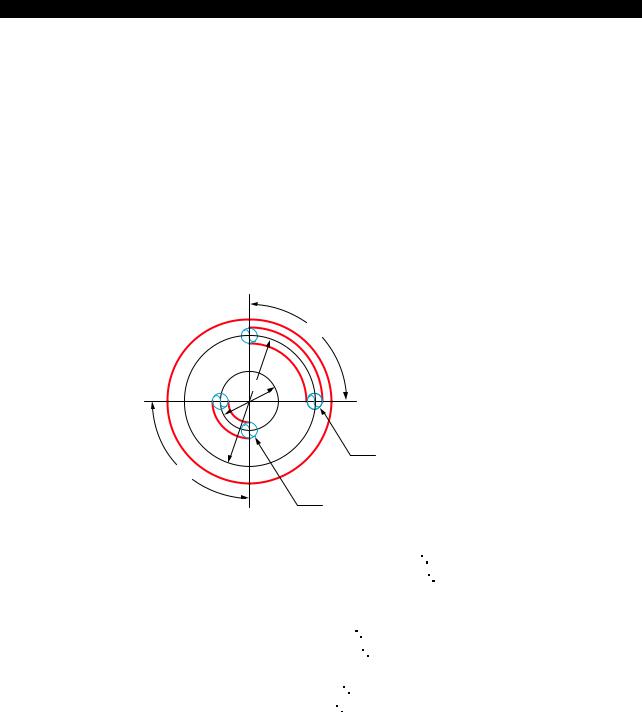
5238-E P-10
SECTION 1 PROGRAM CONFIGURATIONS
10.Determining Feedrate for Cutting along C-Axis
10-1. Cutting by Controlling the C-axis Only
Although it is possible to machine a workpiece by controlling the C-axis, tool movement distance in unit time (one minute) differs according to the diameter of the position to be machined because the feedrate is specified in units of deg/min. This must be taken into consideration when making a program.
[Memo]
To match the unit of the C-axis feed command with the X- and/or Z-axis command, the feedrate command (F) should be calculated by converting 360 into 500 mm. This conversion should also be carried out when only a C-axis command is given.
Example:
90°
200φ
50φ
B
90°
A
Axis movement distance along slot A: π 50/4 = 39 mm
Axis movement distance along slot B: π 200/4 = 156 mm
Therefore, if cutting is carried out at a feedrate of 100 mm per minute, the feedrate (deg/min) of the C-axis is calculated as follows:
Along slot A(deg/min) 100/39 90 = 230
Along slot B(deg/min) 100/156 90 = 58
Convert the unit of feed from «deg/min» into «mm/min».
Slot A: (mm/min) 230/360 500 = 320 (F320)
Slot B: (mm/min) 58/360 500 = 80 (F80)
LE33013R0300300130001
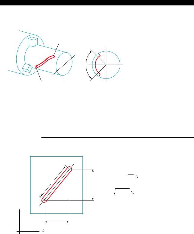
5238-E P-11
SECTION 1 PROGRAM CONFIGURATIONS
10-2. Cutting by Controlling Both C-axis and Z-axis Simultaneously
Example:
A
|
90° |
Point A coordinate value |
X = 80 |
|
Z = 100 |
||
|
C = 120 |
||
|
B |
Point B coordinate value |
X = 80 |
|
Z = 50 |
C = 210
LE33013R0300300140001
When cutting the spiral from A to B with a two-flute end mill under the following cutting conditions, calculate the feedrate of C-axis as explained below:
|
Cutting |
Feed per |
0.05 mm |
|
conditions: |
tooth |
|
|
M-tool speed |
400 min-1 |
Procedure :
1 Calculate the distance between A and B.
A development of the diagram above is indicated below.
L2
90˚
The distance, L1, along the circumference is:
90
L L1 = 80 × π × 360 = 63 (mm)
1
The distance, L2, between A and B is:
L2 = 632+ 502 = 80 (mm)
C
50 mm
LE33013R0300300140002
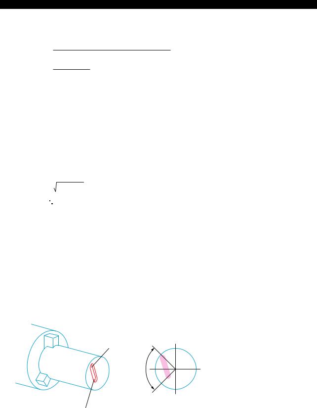
5238-E P-12
SECTION 1 PROGRAM CONFIGURATIONS
2 Calculate the cutting time, T, on the basis of the cutting conditions indicated above to feed the axes along the slot.
L2
T=
(Feed per tooth) x (Number of teeth) x (min-1)
80
=
0.05 × 2 × 400
=2 (min)
LE33013R0300300140003
3 Inside the computer, the distance L3 between A and B is calculated in the following manner.
|
X-axis travel = 50 mm |
|
|
C-axis travel = 90° × 500 mm |
= 125 mm |
|
360° |
(conversion based on 360° = 500 mm)
Therefore, the distance between A and B is calculated as below:
L3 = 502+ 1252
= 135 (mm)
LE33013R0300300140004
4 The feedrate to be specified in the program is approximately calculated as below:
|
F = |
L3 |
= |
135 |
= 67.5 |
|
|
T |
2 |
||||
LE33013R0300300140005
Specify F67.5 in the program.
10-3. Cutting by Controlling Both C-axis and X-axis Simultaneously
Example:
|
Point A coordinate value |
X = 80 |
|
Z = 100 |
|
|
C = 120 |
|
|
Point B coordinate value |
X = 40 |
|
Z = 100 |
C = 210
LE33013R0300300150001
•The cutting conditions are the same as used in «Cutting by Controlling Both C-axis and Z-axis Simultaneously».
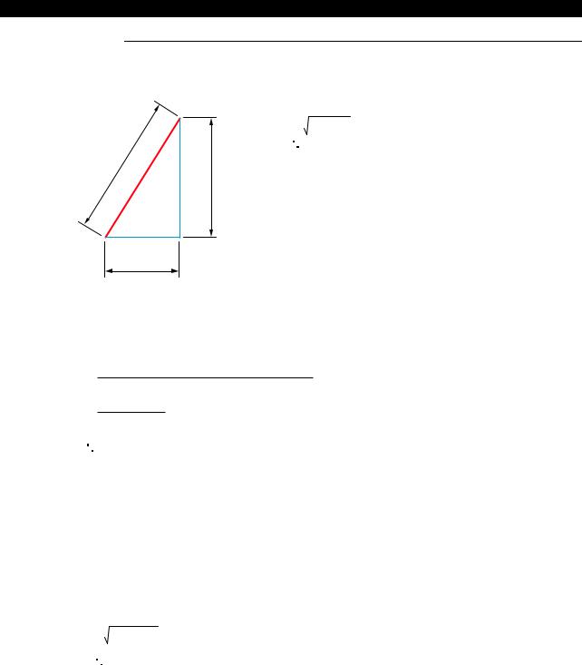
5238-E P-13
SECTION 1 PROGRAM CONFIGURATIONS
Procedure :
1 Calculate the distance between A and B.
A
L2= 402+202
= 44.7 mm
L2
40
B
20
LE33013R0300300150002
2 Calculate the cutting time, T, on the basis of the cutting conditions indicated above to feed the axes along the slot.
L2
T =
(Feed per tooth) × (Number of teeth) × (min-1)
44.7
=
0.05× 2 × 400
=1.12 min
LE33013R0300300150003
3 Inside the computer, the distance L3 between A and B is calculated in the following manner.
X-axis travel = 40 mm
C-axis travel = 90° × 500 mm =125 mm 360°
(conversion based on 360° = 500 mm)
Therefore, the distance between A and B is calculated as below:
L3 = 402+ 1252
= 131.2 mm
LE33013R0300300150004
4 The feedrate to be specified in the program is approximately calculated as below:
F = L3 = 131.2 = 117
T 1.12
LE33013R0300300150005
Specify F117 in the program.

5238-E P-14
SECTION 1 PROGRAM CONFIGURATIONS
10-4. Cutting by Simultaneous 3-axis Control of X-, Z-, and C-axis
Example:
A
90°
B
Point A coordinate value X = 80 Z = 50 C = 120
Point B coordinate value X = 40 Z = 100 C = 210
LE33013R0300300160001
•When cutting a slot on a cone as indicated above, simultaneous 3-axis control of the X-, Z-, and C-axis becomes necessary. The feedrate to be programmed should be calculated in the following manner. Note that the example below assumes the same cutting conditions as in 11- 2. «Cutting by Controlling Both C-axis and X-axis Simultaneously».
Procedure :
1 First, consider the development of the slot on the C-axis and X-axis. In this case, calculation of the feedrate is possible in the same manner as in «Cutting by Controlling Both C-axis and X- axis Simultaneously» .
The C and X-axis travel component, L2, is:
L3 = 402+ 202
= 44.7 mm
LE33013R0300300160002
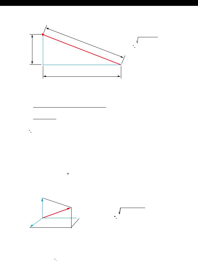
C-axis travel = 90
5238-E P-15
SECTION 1 PROGRAM CONFIGURATIONS
2 Calculate the actual distance between A and B from L2 calculated in (1).
A
= 67.1
L2
 B
B
Z-axis travel
LE33013R0300300160003
3 Calculate the cutting time T for distance L4:
L4
T=
(Feed per tooth) x (Number of teeth) x (min-1)
67.1
=
0.05× 2 × 400
=1.68 min
LE33013R0300300160004
4 Inside the computer, distance L5 between A and B is calculated in the following manner.
X-axis travel = 40 mm
Z-axis travel = 50 mm
500 mm = 125 mm
365
(conversion based on 360 = 500 mm)
C
L5
 Z
Z
L5 = 402+502+1252
= 140.4 mm
X
LE33013R0300300160005
5 The feedrate to be specified in the program is approximately calculated as below:
F = L5 = 140.4 = 83.6
T 1.68
LE33013R0300300160006
Specify F83.6 in the program.

5238-E P-16
SECTION 2 COORDINATE SYSTEMS AND COMMANDS
SECTION 2 COORDINATE SYSTEMS AND COMMANDS
1.Coordinate Systems
1-1. Coordinate Systems and Values
To move the tool to a target position, the reference coordinate system must be set first to define the target position, and the target position is defined by coordinate values in the set coordinate system. There are the three types of coordinate system indicated below. A program coordinate system is used for programming.
•Encoder coordinate system
•Machine coordinate system
•Program coordinate system
1-2. Encoder Coordinate System
An encoder is used to detect the position of a numerically controlled axis. The encoder coordinate system is established based on the position data output by the encoder.
The position data directly output from the encoder is not displayed on the screen, and this coordinate system may be disregarded in daily operation.
1-3. Machine Coordinate System
The reference point in the machine is referred to as the machine zero and the coordinate system which has its origin at the machine zero is called the machine coordinate system. The machine zero is set for each individual machine using system parameters and it is not necessary to change the setting after the installation of the machine.
If «0» is set for the encoder zero point offset (system parameter), the machine coordinate system agrees with the encoder coordinate system.
1-4. Program Coordinate System
The coordinate system used as the reference for program commands is called the program coordinate system.
The position of the origin of the program coordinate system varies according to the kind of workpieces to be machined and the origin is set at the required position by setting the zero offset data. The program coordinate system used for machining a specific kind of workpiece is thus defined based on the set origin.
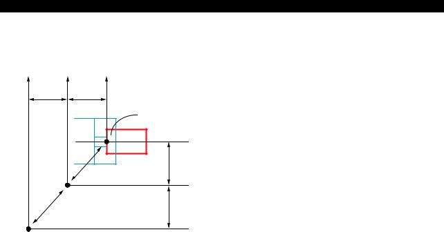
5238-E P-17
SECTION 2 COORDINATE SYSTEMS AND COMMANDS
Although the origin of a program coordinate system (program zero) can be set at any position, it is usually set on the centerline of a workpiece for the X-axis and at the left end face of workpiece for the Z-axis.
|
Zd |
Zm |
Zp |
|
|
Z1 |
Z2 |
||
|
Program zero |
|||
|
Program coordinate |
|||
|
system |
|||
|
Xp |
|||
|
X2 |
|||
|
Machine coordinate |
|||
|
system |
Xm |
||
|
Machine zero |
X1 |
||
|
Xd |
Zero point of encoder
Xd, Zd : Output value of position encoder (0: Zero point of position encoder)
Xm, Zm : Coordinate values in the machine coordinate system (0: Machine zero)
|
Xp, Zp |
: Coordinate values in the program coordinate system |
|
(0: Program zero) |
|
|
X1, Z1 |
: Offset amount of position encoder |
|
X1, Z1 |
: Offset amount of position encoder |
LE33013R0300400040001
![]()
5238-E P-18
SECTION 2 COORDINATE SYSTEMS AND COMMANDS
2.Coordinate Commands
2-1. Controlled Axis
• The following table lists the addresses necessary for axis control.
|
Address |
Contents |
||
|
X |
Controlled axis in the direction parallel to the |
||
|
workpiece end face |
|||
|
Linear axis |
|||
|
Z |
Controlled axis in the direction parallel to the |
||
|
workpiece longitudinal direction. |
|||
|
Rotary axis |
C |
Rotary axis in a plane orthogonal to Z-axis |
|
•A command used to move an axis consists of an axis address, a direction of movement, and a target point.
For the designation of a target point, two different methods are available: absolute commands and incremental commands. With absolute commands, the target point is specified using the coordinate values in the program coordinate system and with incremental commands the target point is defined by relative movement distance in reference to the actual position.
For details of absolute and incremental commands, refer to «Absolute and Incremental commands».
•The basic coordinate system is a right-hand orthogonal coordinate system that is fixed on a workpiece.
Single-saddle NC lathe
X-axis
 Z-axis
Infeed direction …. X-axis
Directions of turret motion:
Longitudinal direction … Z-axis
LE33013R0300400050001

5238-E P-19
SECTION 2 COORDINATE SYSTEMS AND COMMANDS
Two-saddle NC lathe
X-axis + 
Turret A (upper turret)
— +
—  Z-axis
Turret B (lower turret)
+
X-axis
Infeed
direction X-axis
Directions of turret motion:
Longitudinal Z-axis direction
LE33013R0300400050002
C-axis coordinate system
|
Negative direction |
C90˚ |
Positive direction |
|
M16 |
M15 |
|
|
C90˚ |
C270˚ |
C180˚ Chuck
(Viewed from tailstock)
LE33013R0300400050003
Rightward rotation is defined as positive direction of C-axis movement and is commanded by M15. M16 is used to specify C-axis movement in the negative direction.

5238-E P-20
SECTION 2 COORDINATE SYSTEMS AND COMMANDS
2-2. Commands in Inch System
If the inch/metric switchable specification is selected, it is possible to specify dimensions in the inch unit system. Even if dimensions are specified in the inch system values in a part program, the NC processes the data on the basis of metric system values. The unit system to be selected for data input is determined according to the setting of an NC optional parameter (UNIT). The actual unit system for data input can be checked on the NC optional parameter (UNIT) screen.
[Supplement]
In the conversion from the inch system data to the metric system data, used for internal processing by the NC, real data values below the minimum input unit are rounded off. Integer data values are truncated.
2-3. Position of Decimal Point
It is possible to select the unit system of the place of a decimal point. Units of the data available with the control are shown below and the unit to be employed can be selected by entering a proper parameter data. Once the unit system of the command data is established, it applies to all numerical data to be entered, such as MDI operation and zero offset data.
2-3-1. Metric System
•1 m
•10 m
•1 mm

5238-E P-21
SECTION 2 COORDINATE SYSTEMS AND COMMANDS
2-3-2. Inch System (Inch/metric switchable specification):
•1/10000 inch
•1 inch
Unit Data Table (Value for data «1»)
|
Dimension |
Metric System |
Inch System |
|||||
|
1 m |
10 m |
1 mm |
1/10000 inch |
1 inch |
|||
|
Length: |
|||||||
|
X, Z, I, K, D, H, L, |
0.001 (mm) |
0.1 (mm) |
1 (mm) |
0.0001 (inch) |
1 (inch) |
||
|
U, W |
|||||||
|
Feed (/rev): |
0.001 (mm/rev) |
0.01 (mm/rev) |
1 (mm/rev) |
0.0001 (inch/ |
1 (inch/rev) |
||
|
F, E |
rev) |
||||||
|
Feed (/min): |
0.1 (mm/min) |
1 (mm/min) |
1 (mm/min) |
0.01 (inch/min) |
1 (inch/min) |
||
|
A, B, C |
|||||||
|
Angle: |
0.001 (°) |
0.01 (°) |
1 (°) |
0.001 (°) |
1 (°) |
||
|
A, B, C |
|||||||
|
Time: |
0.01 (sec) |
0.1 (sec) |
1 (sec) |
0.01 (sec) |
1 (sec) |
||
|
F, E |
|||||||
|
Spindle |
|||||||
|
min-1: |
1 (min-1) |
1 (min-1) |
1 (min-1) |
1 (min-1) |
1 (min-1) |
||
|
S |
|||||||
|
Surface speed: |
1 (m/min) |
1 (m/min) |
1 (m/min) |
1 (feet/min) |
1 (feet/min) |
||
|
S |
|||||||
|
Example 1: 1 mm unit system |
|||||||
|
Commanding: |
|||||||
|
• 0.001 mm movement of X-axis |
X0.001 |
||||||
|
• |
10 mm movement of X-axis |
X10 |
|||||
|
• |
100.00 mm movement of X-axis |
X100.01 |
|||||
|
• Feedrate of 0.23456 mm/rev. |
F0.23456 |
||||||
|
The following commands are all handed as X1 mm: |
|||||||
|
X1 |
|||||||
|
X1.0 |
|||||||
|
X1.00 |
|||||||
|
X1.000 |
|||||||
|
Example 2: 10 mm unit system |
|||||||
|
Commanding: |
|||||||
|
• 0.001 mm movement of X-axis |
X0.1 |
||||||
|
• |
10 mm movement of X-axis |
X1000 |
|||||
|
• 100.010 mm movement of X-axis |
X10001 |
||||||
|
• Feedrate of 0.23456 mm/rev. |
F23.456 |
||||||
|
Example 3: 1 mm unit system |
|||||||
|
Commanding: |
|||||||
|
• 0.001 mm movement of X-axis |
X0.1 |
||||||
|
• |
10 mm movement of X-axis |
X10000 |
|||||
|
• |
100.010 mm movement of X-axis |
X100010 |

5238-E P-22
SECTION 2 COORDINATE SYSTEMS AND COMMANDS
|
• Feedrate of 0.23456 mm/rev. |
F234.56 |
[Supplement]
For F words, numerical data smaller than the selected unit system is effective if it consists of up to eight digits.
F1.2345678 Acceptable
F100.000001 Alarm (9 digits)
LE33013R0300400090001
2-4. Absolute and Incremental Commands (G90, G91)
The amount of axis movement can be expressed by either absolute commands or incremental commands.
(1)Absolute commands Designated with G90
Commanded values are coordinate values in the program coordinate system. When the control is reset, it is in the G90 mode.
(2)Incremental commands Designated with G91
Commanded values are the travel from the actual position to the target position.
Example:
(Positioning from point (1) to point (2)):
|
(2) X100 |
Z50 |
|
|
X |
100 |
|
|
25 |
||
|
(1) X50 |
Z150 |
Absolute
G00 X50 Z150 (1)
X100 Z50 (2) Incremental
G00 X50 Z150 (1)
*G91 X50 Z-100 (2)
*Designate dimensional differences between points (2) and (1).
LE33013R0300400100001
[Supplement]
1)In incremental programming, the X word should be expressed as a diameter.
2)It is not permissible to specify both G90 and G91 in the same block.

5238-E P-23
SECTION 2 COORDINATE SYSTEMS AND COMMANDS
2-5. Diametric and Radial Commands
In a turning operation, the workpiece is rotated while being is machined. Due to the nature of the turning operation, the tool cuts a circle with a radius equivalent to the distance from the center of rotation to the tool nose position. In a program, X-axis commands specify the diameter of the circle to be cut. If a command of «X100» is specified, for example, the actual position data displayed on the screen is «100» and the workpiece is machined to a cylinder of 100-mm diameter.
In compound operations, commands in the X-axis direction are specified as diametric values too, although this type of operation is not a turning operation. In the coordinate conversion mode, however, the radial values (actual length in an orthogonal coordinate system) must be specified for both X- and Y-axis commands.

5238-E P-24
SECTION 3 MATH FUNCTIONS
SECTION 3 MATH FUNCTIONS
1.Positioning (G00)
[Function]
Each axis moves independently from the actual position to the target position at its own rapid feedrate. At the start and end of axis movement, it is automatically accelerated and decelerated. [Programming format]
G00 X__ Z__ C__
X/Z/C : Indicates the target position for positioning operation.
[Details]
•In G00 mode positioning, execution of the commands in the next block begins only after the positioning at the target position given in the current block is completed.
•Non-linear interpolation mode:
The axes move independently of each other at a rapid feedrate. Therefore, the resultant tool path is not always a straight line.
|
X |
Target position |
|
Actual position |
|
|
Z |
|
|
LE33013R0300500010001 |
|
|
[Supplement] |
The rapid feedrates of each axis are set by the machine specifications.
2.Linear Interpolation (G01)
[Function]
The G01 command specifies the axes to move directly from the current position to the specified coordinate values at the specified feedrate.
[Programming format] G01 X__ Z__ C__ F__
X, Z, C : Target point (end point)
F : Feedrate.
The specified value remains effective until updated by another value.

5238-E P-25
SECTION 3 MATH FUNCTIONS
[Supplement]
1)The feedrate becomes zero when the NC is reset.
2)The feedrate for each axis is indicated below. (Calculate feedrate for X and Z-axes as incremental values.)
G01 XxZzFf Calculation of feedrates:
|
X-axis feedrate |
FX = |
x |
f |
|
L |
|||
|
Z-axis feedrate |
FZ = |
z |
f |
|
L |
where L3 = x2+z2
x, z, f: Command values specified in a program

5238-E P-26
SECTION 3 MATH FUNCTIONS
3.Circular Interpolation (G02, G03)
[Function]
Circular interpolation can be used to generate a cutting path which follows an arc. [Programming format]
|
G02 |
X__ Z__ {I |
__LK____ } |
F__ |
|
|
(G03) |
||||
|
LE33013R0300500030001 |
||||
|
G02 |
: Direction of rotation |
: Sets clockwise rotation |
||
|
G03 |
: Direction of rotation |
: Sets counterclockwise rotation |
||
|
X, Z |
: |
G90 mode |
: Set the end point in the program coordinate system |
|
|
X, Z |
: |
G91 mode |
: Sets the end point in reference to the starting point |
|
|
(values should include signs) |
||||
|
I, K : Set the distance of the center of the arc from the starting point (values should include |
||||
|
signs) |
||||
|
L |
: Sets the radius of the arc |
|||
|
F |
: Sets the feedrate |
|||
|
[Details] |
•The two directions of rotation, clockwise and counterclockwise, are defined when viewing the Z- X plane from the positive direction of the axis orthogonal to the plane in the right-hand orthogonal coordinate system.
X
GO3
GO2
 Z
Z
LE33013R0300500030002
•The end point of an arc is defined as an absolute value or an incremental value depending on the G90/G91 selection.
•The center of an arc is expressed by I and K, which correspond to X and Z respectively. That is, I expresses the X coordinate value and K the Z coordinate value of the center of the arc in reference to the starting point of the arc.

5238-E P-27
SECTION 3 MATH FUNCTIONS
For I and K, signed incremental values are used regardless of the mode, G90 or G91.
|
X(I) |
||
|
Z1 |
Arc center |
|
|
Arc end point |
||
|
R |
I |
|
|
X1 |
φ |
|
|
Arc start point |
K1 |
|
|
Z(K) |
|
X(I) |
Z1 |
|||
|
Arc end point |
||||
|
X1 |
φ |
R |
||
|
Arc |
Arc start point |
|||
|
center |
I |
|||
|
K |
Z(K) |
G02: Both I and K values are positive
Z1, X1 indicate the coordinate values of the arc end point.
G03: Both I and K values are positive
Z1, X1 indicate the coordinate values of the arc end point
LE33013R0300500030003
Determining Sign and Numeric Value of I and K Words:
See the figure below. Assume the coordinate system has its origin at the arc start point. Draw a right-angled triangle taking the segment connecting the arc center and arc start point as the hypotenuse. The length of side (b), parallel to the Z-axis, is the value of the K word and that of side (c), parallel to the X-axis, is the value of the I word.
Concerning the sign of these words, when side (b) lies in the positive direction of the assumed coordinate system, it is taken as a positive value and when it lies in the negative direction, it is negative. The sign of I words is determined in a similar way. That is, when side (c) lies in the positive direction of the coordinate system, the I word has a positive value and when it lies in the negative direction, the I word has a negative value.
|
X-axis |
||
|
Arc start point |
I + |
|
(c)(a)
(b)
|
I — |
Arc center |
|
|
I — K — |
||
|
IOD cutting |
||
|
ID cutting |
K — |
|
|
K — |
I + |
|
|
I — |
K — |
|
|
I + K — |
LE33013R0300500030004
![]()
5238-E P-28
SECTION 3 MATH FUNCTIONS
•Direct Radius Command
It is possible to execute circular interpolation by specifying the X and Z coordinate values of the target point and the radius of the arc instead of using I and K commands.
[Supplement]
•The G code used to call circular interpolation is G02 or G03, as when using I and K.
•The radius of the arc is expressed by an L word which must have a positive value.
•A block containing an L word without a K or I word is an arc radius command.
•When expressing an arc by its radius, the commands must contain both X and Z words.
•If either of them is omitted, an alarm results.
•If an L word is specified in a block containing I and/or K word, an alarm results.
•If the distance from the current position to the target point (end point) is larger than two times the specified radius, an alarm results since circular interpolation cannot be performed.
•In direct arc command programming, one arc command yields two arcs; one with central angle less than 180, and another larger than 180. The arc with central angle less than 180 is selected.
To obtain the arc whose central angle is greater than 180, specify «CALRG» in the block commanding circular interpolation.
•The direct radius command programming is effective in: LAP
Tool nose radius compensation mode Subprograms
•Incremental programming mode (G91)
In direct radius command programming, the control automatically calculates the coordinates of the center of the arc, I and K, from the programmed radius L and the coordinates of the end point, X and Z, to perform circular interpolation.
The program for the example in the figure to the right is as follows.
Program:
N1 G01 X1 Z1 F1
N2 G03 X2 Z2 Lr
With the commands above,
the arc indicated by a thick solid line is obtained.
|
+X N2 |
N1 |
|
|
(Z2,X |
2) |
|
|
(Z1,X1) |
||
r
 r Center
 +Z
+Z
To move the tool along the arc indicated by dashed lines, program as follows:
N1 G01 X1 Z1 F1
N2 G03 CALRG X2 Z2 Lr
LE33013R0300500030005
•Feedrates
The feedrate during circular interpolation is the feedrate component tangential to the arc.

5238-E P-29
SECTION 3 MATH FUNCTIONS
[Supplement]
1)If I or K is omitted, I0 or K0 applies.
2)I and K values should be specified as radii.
3)An arc extending into two or more quadrants can be specified by the commands in a single block.
4)If either X or Z is omitted, circular interpolation is possible within one quadrant.
5)An alarm will be activated if the difference in radius between the start and end point of an arc is greater than the value set for optional parameter (OTHER FUNCTION 1) No. 6 Allowable error in circular interpolation.

5238-E P-30
SECTION 3 MATH FUNCTIONS
4.Automatic Chamfering
When cutting a workpiece, it is often necessary to chamfer a sharp edge (either straight-line chamfering (C-chamfering) or rounding). Although such chamfering can be accomplished using conventional interpolation commands (G01, G02, G03), the automatic chamfering function permits chamfering to be done with a simple program.
For chamfering at any required angle, the automatic any-angle chamfering function should be used. To use the automatic chamfering function, set «1» for optional parameter (OTHER FUNCTION 1) Auto. any-angle chamfering. If the automatic any-angle chamfering function is required, set «anyangle chamfering» for this parameter.
4-1. C-chamfering (G75)
+X
|
(X120.00, Z50.00) |
(X120.00, Z115.00) |
|
E |
D |
C (X120.00, Z120.00)
 B (X110.00, Z120.00)
5C
A (X50.00, Z120.00)
 +Z
+Z
LE33013R0300500050001
To cut the contour shown above along the points A, B, D and E, program as follows: G75 G01 X120 L-5 FDD CR
after positioning the cutting tool at point A.
With the commands above, the cutting tool moves from point A to B and then to D, thus automatically chamfering the corner at 45 with a size of 5 mm.
G75 : Specifies C-chamfering
X120 : X coordinate of Point C
L-5 : Size of chamfered face
The sign is determined by the direction of axis movement;
«+» when the Z-axis (X-axis) moves in the positive direction after X-axis (Z-axis) motion. «-» when the Z-axis (X-axis) moves in the negative direction after X-axis (Z-axis) motion.
When the coordinates of point E are commanded, the cutting tool moves from Point D to Point E. [Details]
•G75 is effective only in the G01 mode. If G75 is specified in another mode, it causes an alarm.
•G75 is non-modal and active only in the commanded block.
•If the axis movement dimension specified in the block calling for automatic chamfering (A — C in the figure above) is smaller than the absolute value of the L word (B — C in the figure above), an alarm results.
•If the axis movement dimensions specified in the block calling for automatic chamfering are zero both for X and Z, or if neither the X nor the Z value is zero in such a block, an alarm occurs. The block calling for the automatic chamfering mode can contain only one dimension word, either X or Z.

5238-E P-31
SECTION 3 MATH FUNCTIONS
•The automatic chamfering program is effective in: LAP
Tool nose radius compensation mode
[Program example]
|
90.00 |
|||||||||||
|
10.00 |
40.00 |
5C |
60.00 |
||||||||
|
4C |
|||||||||||
|
2C |
3C |
||||||||||
|
160.00φ |
100.00φ |
||||||||||
|
60.00φ |
|||||||||||
|
: |
|||||||||||
|
: |
|||||||||||
|
N101 |
G01 |
X60 |
Z92 |
F0.1 |
|||||||
|
N102 |
G75 |
Z60 |
F0.05 |
L3 |
|||||||
|
N103 |
G75 |
X100 |
L-2 |
||||||||
|
N104 |
G75 |
Z40 |
L4 |
||||||||
|
N105 |
G75 |
X160 |
L-5 |
||||||||
|
N106 |
Z10 |
||||||||||
|
: |
|||||||||||
|
: |
LE33013R0300500050002

5238-E P-32
SECTION 3 MATH FUNCTIONS
4-2. Rounding (G76)
+X
|
(X120.00, Z50.00) |
(X120.00, Z115.00) |
|
E |
D |
|
C (X120.00, Z120.00) |
|
|
B (X110.00, Z120.00) |
|
|
5R |
 A (X50.00, Z120.00)
 +Z
+Z
LE33013R0300500060001
To cut the contour shown above along the points A, B, D and E, program as follows: G76 G01 X120 L-5 FDD CR
after positioning the cutting tool at point A.
With the commands above, the cutting tool moves from point A to B and then to D, thus automatically rounding the corner to a radius of 5 mm.
G76 : Specifies rounding of a corner
X120 : X coordinate of Point C
L-5 : Radius of rounding circle
The sign is determined by the direction of axis movement;
«+» when the Z-axis (X-axis) moves in the positive direction after the X-axis (Z-axis) motion.
«-» when the Z-axis (X-axis) moves in the negative direction after the X-axis (Z-axis) motion.
When the coordinates of point E are commanded, the cutting tool moves from point D to point E. [Details]
•G76 is effective only in the G01 mode. If G76 is specified in a mode other than G01, an alarm occurs.
•G76 is non-modal and active only in the commanded block.
•The rounding describes a 1/4 circle with the radius specified by an L word.
•If the axis movement dimension specified in the block calling for automatic chamfering (A — C in the figure above) is smaller than the absolute value of the L word (B — C in the figure above), an alarm results.
•If the axis movement dimensions specified in the block calling for automatic chamfering are zero both for X and Z, or if neither X nor Z value is zero in such a block, an alarm occurs.
The block calling for automatic chamfering mode can contain only one dimension word, either X or Z.
•The automatic chamfering program is effective in: LAP
Tool nose radius compensation mode

5238-E P-33
SECTION 3 MATH FUNCTIONS
[Program Example]
90.00 
|
40.00 |
60.00 |
||||||||||
|
10.00 |
|||||||||||
|
5R |
|||||||||||
|
4R |
|||||||||||
|
2R |
3R |
||||||||||
|
160.00φ |
100.00φ |
||||||||||
|
60.00φ |
|||||||||||
|
N101 |
G01 |
X60 |
Z92 |
F0.1 |
|||||||
|
N102 |
G76 |
Z60 |
F0.05 |
L3 |
|||||||
|
N103 |
G76 |
X100 |
L-2 |
||||||||
|
N104 |
G76 |
Z40 |
L4 |
||||||||
|
N105 |
G76 |
X160 |
L-5 |
||||||||
|
N106 |
Z10 |
LE33013R0300500060002

5238-E P-34
SECTION 3 MATH FUNCTIONS
4-3. Automatic Any-Angle Chamfering
When cutting a workpiece, it is often necessary to chamfer the sharp (C-chamfer or R-chamfer) corners and edges. If chamfering is required on edges having an angle other than 90°, programming chamfering using G01, G02 and G03 commands is not easy. This automatic chamfering function can program chamfering easily.
[Programming Examples]
(1) C-Chamfering (G75)
|
+X |
||||||||||
|
J (X100, Z30) |
I (X100, Z72.453) |
|||||||||
|
H (X89.608, Z81.453) |
||||||||||
|
6C |
120˚ |
(X60, Z114) |
||||||||
|
(X68.660, Z87,5) G |
5C |
|||||||||
|
D |
||||||||||
|
(X60, Z90) F |
E |
C (X60, Z120) |
||||||||
|
6C B (X48, Z120) |
||||||||||
|
(X60, Z95) |
||||||||||
|
A (X20, Z120) |
||||||||||
|
+Z |
||||||||||
|
N100 |
G00 |
X20 |
Z120 |
F∆∆∆ |
||||||
|
N110 |
G75 |
G01 |
X60 |
L6 |
||||||
|
N120 |
G75 |
Z90 |
L5 |
|||||||
|
N130 |
G75 |
A120 |
X100 |
L6 |
||||||
|
N140 |
Z30 |
LE33013R0300500070001
With the program above, the cutting tool moves from point A to point J in the sequence A, B, D, E, G, H, I and J, thus accomplishing chamfering of B-D, E-G and H-I.
[Supplement]
Angle commands (A) are designated in reference to the Z-axis.

5238-E P-35
SECTION 3 MATH FUNCTIONS
(2) R-Chamfering (G76)
|
+X |
||||||||||||
|
J (X100, Z30) |
I (X100, Z73.884) |
|||||||||||
|
H (X92, Z80.762) |
||||||||||||
|
8R |
G |
120˚10R |
(X60, Z114) |
|||||||||
|
(X70, Z87.113) |
D |
C (X60, Z120) |
||||||||||
|
(X60, Z90) |
F |
|||||||||||
|
E |
||||||||||||
|
(X60, Z95.774) |
6R |
B (X48, Z120) |
||||||||||
|
A (X20, Z120) |
||||||||||||
|
+Z |
||||||||||||
|
N100 |
G00 |
X20 |
Z120 |
F∆∆ |
||||||||
|
N110 |
G76 |
G01 |
X60 |
L6 |
||||||||
|
N120 |
G76 |
Z90 |
L10 |
|||||||||
|
N130 |
G76 |
A120 |
X100 |
L8 |
||||||||
|
N140 |
Z30 |
LE33013R0300500070002
With the program above, the cutting tool moves from point A to point J in the sequence A, B, D, E, G, H, I and J, thus accomplishing chamfering of B-D, E-G, and H-I.
[Supplement]
With the C-chamfer function, axis movements in the G00, G01, G34 and G35 modes can be designated by simply entering an angle command A without X and/or Z coordinate data.
Example:
(X0, Z0)
-150˚
(X1, Z1)
 -160˚ (X2, Z2)
|
G00 |
X0 |
Z0 |
CR |
|
|
G01 |
A-150 |
F∆ |
CR |
|
|
X2 |
Z2 |
A-160 |
CR |
LE33013R0300500070003
(X1, Z1) should not be designated; it is automatically generated in the NC.

5238-E P-36
SECTION 3 MATH FUNCTIONS
[Supplement]
1)Both G75 and G76 are effective only in the G01 mode and if they are designated in a mode other than G01an alarm occurs.
2)If the axis movement amount is smaller than the chamfering size, an alarm occurs.
3)Chamfering is possible only at corners between two lines. Chamfering at corners between two arcs, between a line and an arc, or between an arc and a line is impossible. If chamfering at such corners is attempted, an alarm occurs.
4)The chamfering command is effective both in the LAP and nose radius compensation mode.
5)If only an angle command A is designated in G00, G01, G34, or G35 mode operations, the next axis movement command must contain A, X and Z commands so that the end point of the line commanded can be defined. If these commands are not designated and the end point cannot be defined, then an alarm occurs.
6)If chamfering commands G75 and G76 are designated without axis movement commands X and Y or if they are designated only with an A command, the control reads the commands in the next sequence to calculate the point of intersection automatically. Therefore, if the next sequence does not contain adequate data for this calculation, an alarm occurs.
5.Torque Limit and Torque Skip Function
To transfer a workpiece from the first-process chuck to the second-process chuck with multi-process models*, the end face of the second-process chuck jaws must be pushed against the workpiece for stable workpiece seating. The torque limit command and the torque skip command are used to control the torque of the second-process chuck feed servomotor and to push the workpiece with the optimal thrust.
* Multi-process models include sub spindle models, opposing two-spindle models, etc.
5-1. Torque Limit Command (G29)
[Function]
Prior to workpiece transfer, designate the torque limit command to control the maximum torque of the second-process chuck feed servomotor.
[Program Format] G29 P D __
(Designate an axis to be fed: Z or W, for D.) [Details]
•The torque limit value is set as a percentage, taking the rated torque of the axis feed servomotor as 100%.
•The maximum torque limit value is set for optional parameter (OTHER FUNCTION 2).
5-2. Torque Limit Cancel Command (G28)
[Function]
The torque limit cancel command cancels the maximum torque limit designated with G29. When this command is designated, the axis feed motor can output its maximum output torque. [Programming format]
G28

5238-E P-37
SECTION 3 MATH FUNCTIONS
5-3. Torque Skip Command (G22)
[Programming format]
G22 Z__ D__ L__ F__ PZ =__ Z : Target point (mm)
D: Distance between the target point and the approaching point as an incremental value (mm)
L: Distance between the target point and the virtual approaching point as an incremental value (mm)
|
F |
: |
Feedrate (mm/min or mm/rev) |
|
PZ |
: |
Preset torque value (%) |
[Details]
•For the target point and the set torque value, designate the axis to be fed..
•An alarm (alarm A 1220) occurs if the preset torque value is not reached when the secondprocess chuck has moved to the virtual approaching point.
•Designate a value equal to or smaller than «2.5 m/min (8.20 fpm)» for F.
•Before setting a value for PZ, check the actual motor torque value** at axis feed at the feedrate designated by F, and set a value for PZ which is larger than the actual torque value by 10%.
**Check the RLOAD value displayed on the axis data page of the CHECK DATA screen.
If the preset torque value is too small, it is reached during approaching motion, resulting in an occurrence of alarm 1219.
First-process chuck
L D
Z
Second-process chuck
The explanation here is for a case in which a workpiece is transferred from the first-process
 chuck to the second-process chuck.
1.The second-process chuck approaches the workpiece at feedrate F.
2.The feedrate is reduced to 1/5 of F at the approaching point (Z — D) point).
3.The second-process chuck contacts the workpiece at target point Z.
The servomotor is controlled so that the second-process chuck is kept pushed against the workpiece.
4.When the motor torque reaches the preset value, the NC recognizes workpiece seating to be complete, and the next program block is executed.
LE33013R0300500110001
Feedrate F → F/5 Z : Target point
D : Distance between the target point and the approaching point as an incremental value
L : Distance between the target point and the virtual approaching point as an incremental value
 Loading…