-
Contents
-
Table of Contents
-
Bookmarks
Quick Links
TABLE OF CONTENTS
Before driving
1
2
When driving
Interior features
3
Maintenance and
4
care
When trouble
5
arises
Vehicle specifi-
6
cations
Index
URBAN CRUISER_OM_OM52C63E_(EE)
Adjusting and operating features such as door locks,
mirrors, and steering column
Driving, stopping and safe-driving information
Air conditioning and audio systems, as well as other in-
terior features for a comfortable driving experience
Cleaning and protecting your vehicle, performing do-it-
yourself maintenance, and maintenance information
What to do if the vehicle needs to be towed, gets a flat
tire, or is involved in an accident
Detailed vehicle information
Alphabetical listing of information contained in this man-
ual
1
Summary of Contents for Toyota Urban Cruiser
- Manuals
- Brands
- TOYOTA Manuals
- Other
- URBAN CRUISER
Manuals and User Guides for TOYOTA URBAN CRUISER. We have 3 TOYOTA URBAN CRUISER manuals available for free PDF download: Owner’s Manual, Brief Manual, Dimensions
Toyota URBAN CRUISER Owner’s Manual (544 pages)
Brand: Toyota
|
Category: Automobile
|
Size: 28.85 MB
Table of Contents
-
Table of Contents
2
-
1 Before Driving
31
-
Key Information
31
-
Keys
32
-
-
Opening, Closing and Locking the Doors Smart Entry & Start System
36
-
Opening, Closing
36
-
Smart Entry & Start
36
-
System
36
-
Wireless Remote Control
57
-
Side Doors
66
-
Back Door
70
-
-
-
Adjustable Components
75
-
Front Seats
75
-
Rear Seats
77
-
Head Restraints
83
-
Seat Belts
86
-
Steering Wheel
95
-
Inside Rear View Mirror
96
-
Outside Rear View Mirrors
98
-
-
Opening and Closing
101
-
Power Windows
101
-
-
Refueling
105
-
The Fuel Tank Cap
105
-
-
Theft Deterrent System
110
-
Engine Immobilizer
110
-
System
110
-
Engine Immobilizer
111
-
-
Double Locking System
118
-
Alarm
120
-
-
Safety Information
124
-
Correct Driving Posture
124
-
SRS Airbags
126
-
Airbag Manual On-Off System
140
-
Child Restraint Systems
143
-
Installing Child Restraints
153
-
2 When Driving
167
-
-
Driving Procedures
168
-
Driving the Vehicle
168
-
Engine (Ignition) Switch (Vehicles Without Smart Entry & Start System)
181
-
Engine (Ignition) Switch (Vehicles with Smart Entry & Start System)
185
-
Manual Transmission
189
-
Turn Signal Lever
193
-
Parking Brake
194
-
Horn
195
-
-
Instrument Cluster
196
-
Gauges and Meters
196
-
Indicators and Warning Lights
198
-
Multi-Information Display
202
-
-
Operating the Lights
207
-
Headlight Switch
207
-
Fog Light Switch
211
-
Windshield Wipers and Washer
213
-
Rear Window Wiper and Washer
215
-
-
Using Other Driving Systems
217
-
Stop & Start System
217
-
Driving Assist Systems
223
-
Four-Wheel Drive Lock (4WD Models)
229
-
Diesel Particulate Filter System (Diesel Engine Only)
230
-
-
Driving Information
232
-
Cargo and Luggage
232
-
Winter Driving Tips
235
-
Trailer Towing
239
-
System
250
-
-
Automatic Air Conditioning System
259
-
Power Heater
267
-
Rear Window and Outside Rear View Mirror Defoggers
270
-
-
Using the Audio System
272
-
Audio System Types
272
-
Using the Radio
274
-
Using the CD Player
278
-
Playing Back MP3 and WMA Discs
285
-
Optimal Use of the Audio System
293
-
Using the AUX Port
296
-
Using the Steering Switches
297
-
-
Using the Hands-Free System
299
-
Hands-Free System
299
-
(For Cellular Phone)
299
-
-
Using the Hands-Free System
306
-
Making a Phone Call
310
-
Setting a Cellular Phone
314
-
Security and System Setup
318
-
Using the Phone Book
322
-
-
Using the Interior Lights
328
-
Interior Lights List
328
-
Personal Lights
329
-
-
-
Using the Storage Features
330
-
List of Storage Features
330
-
Glove Boxes
331
-
Cup Holders
332
-
Bottle Holders
334
-
Auxiliary Box
335
-
-
-
Other Interior Features
336
-
Sun Visors
336
-
Vanity Mirror
337
-
Clock
338
-
Portable Ashtray
339
-
Cigarette Lighter
340
-
Seat Heaters
341
-
Assist Grips
343
-
Floor Mat
344
-
Luggage Compartment Features
346
-
-
4 Maintenance and Care
349
-
Maintenance and Care Cleaning and Protecting
350
-
The Vehicle Exterior
350
-
Maintenance and Care
350
-
Cleaning and Protecting the Vehicle Interior
354
-
-
Maintenance
358
-
Requirements
358
-
-
Do-It-Yourself Maintenance
358
-
Do-It-Yourself Service
362
-
Precautions
362
-
Do-It-Yourself Maintenance
363
-
Hood
366
-
Positioning a Floor Jack
368
-
Engine Compartment
370
-
Tires
388
-
Tire Inflation Pressure
391
-
Wheels
393
-
Air Conditioning Filter
395
-
Key Battery
398
-
Checking and Replacing Fuses
402
-
Light Bulbs
418
-
-
5 When Trouble Arises
427
-
-
Essential Information
427
-
Emergency Flashers
428
-
If Your Vehicle Needs to be Towed
429
-
If You Think Something Is Wrong
437
-
Fuel Pump Shut off System (Gasoline Engine)
438
-
-
Steps to Take in an Emergency if a Warning Light Turns on or a Warning Buzzer Sounds
439
-
Steps to Take in an
439
-
If a Warning Light Turns on or a Warning Buzzer Sounds
439
-
If You Have a Flat Tire (Vehicles with a Spare Tire)
449
-
If You Have a Flat Tire (Vehicles Without a Spare Tire)
464
-
If the Engine will Not Start
480
-
If You Lose Your Keys
482
-
If You Cannot Operate the Back Door Opener
483
-
If the Electronic Key Does Not Operate Properly
484
-
If the Battery Is Discharged
487
-
If Your Vehicle Overheats
493
-
If You Run out of Fuel and the Engine Stalls (Diesel Engine)
497
-
If the Vehicle Becomes Stuck
500
-
If Your Vehicle Has to be Stopped in an Emergency
502
-
-
Specifications Maintenance Data
506
-
(Fuel, Oil Level, Etc.)
506
-
Specifications
506
-
Fuel Information
523
-
-
Customization
526
-
Customizable Features
526
-
-
Initialization
528
-
Items to Initialize
528
-
Index
529
-
Abbreviation List
530
-
Alphabetical Index
531
-
What to Do if
540
-
Advertisement

Toyota URBAN CRUISER Brief Manual (20 pages)
Brand: Toyota
|
Category: Automobile
|
Size: 4.12 MB
Table of Contents
-
Table of Contents
3
-
Accessing Your Vehicle
4
-
Child Rear Door Protection Lock
5
-
Child Restraint System
5
-
Seat and Seat Belt Adjustment
6
-
Steering Wheel Adjustment
7
-
Instrument Panel Overview
8
-
Steering Wheel Controls
9
-
Instrument Cluster
10
-
Lights
11
-
Wipers
12
-
Electric Window and Window Lock
12
-
Starting Your Vehicle
13
-
Stop & Start System (if Equipped)
13
-
Heating, A/C and De-Misting
14
-
Setting the Clock
15
-
Gear Change
16
-
Four-Wheel Drive Lock (4WD Models)
16
-
Fuel Tank Opening
17
-
Bonnet Opening
17
-
Eco-Driving
18
TOYOTA URBAN CRUISER Dimensions (2 pages)
Brand: TOYOTA
|
Category: Automobile
|
Size: 0.06 MB
Advertisement
Advertisement
Related Products
-
Toyota Fortuner UH9000S
-
Toyota Fortuner UH9080S
-
Toyota Fortuner UH9060S
-
Toyota UZJ100
-
Toyota PT545-00082
TOYOTA Categories
Automobile
Automobile Accessories
Car Navigation system
Sewing Machine
Car Receiver
More TOYOTA Manuals
Toyota URBAN CRUISER: List of Available Documents
Note for Owners:
Guidesimo.com webproject is not a service center of Toyota trademark and does not carries out works for diagnosis and repair of faulty Toyota URBAN CRUISER equipment. For quality services, please contact an official service center of Toyota company. On our website you can read and download documentation for your Toyota URBAN CRUISER device for free and familiarize yourself with the technical specifications of device.
More Automobile Devices:
-
GMC 2007 Canyon
DRIVER INFORMATIONInstrument Panel . . . . . . . . . . . . . . . . . . . . . . . . . . .2Instrument Panel Cluster . . . . . . . . . . . . . . . . . . . . .3Driver Information Center . . . . . . . . . . . . . . . . . . . .4SAFETY & SECURITYSafety Belts . . . . . . . . . . . . . . . . . . . . . . . . . . . . . . . .5Child Comfort Guide . . . . . . . . . . . . . . . . . . . . . . . .6Child Res …
2007 Canyon Automobile, 20
-
Vauxhall Combo
Vehicle features Vehicle featuresComboQuick Reference GuideRefer to Owner’s Manual for detailed information.Illustrations may depict left-hand drive vehicles. Operation is similar for right-hand drive vehicles.Depending on the model variant, special equipmentand accessories, the scope of equipment on yourvehicle may differ from the descriptions in this guide.TS 1716-A-12 / KTA 2742November 2011* …
Combo Automobile, 2
-
Volvo 2003 V40
2 0 0 3 VOLVOS40 & V40This manual deals with the operation and care of your Volvo.Welcome to the worldwide family of Volvo owners. We trust that you will enjoy many years of safe driving in yourVolvo, an automobile designed with your safety and comfort in mind. To help ensure your satisfaction with thisvehicle, we encourage you to familiarize yourself with the equipment descriptions, operating …
2003 V40 Automobile, 85
-
GMC EXPLORER
Conversion VanOwners Manual3 Years/36,000 MilesLimited Warranty To Original Retail BuyerExplorer Van Company, Inc.P.O. Box 4527Warsaw IN 46581-4527574-267-7666www.explorervan.comPrinted in USAAll rights reservedGMC / CHEVROLET …
EXPLORER Automobile, 54
-
Mitsubishi MOTORS Space Runner 1998
001112131415161721222325262731323334353637425152545500109000812General ……………………Engine …………………….Engine Lubrication ………….Fuel ………………………Engine Cooling ……………..Intake and Exhaust …………Engine Electrical ……………Engine and Emission Control ….Clutch …………………….Manual Transmission ………..Automatic Transmis …
Space Runner 1998 Automobile, 1164
Recommended Documentation:
![]()
URBAN CRUISER
(RHD)
AIR CONDITIONING
ENGLISH
INTRODUCTION
IMPORTANT NOTICE
This manual has been designed for technicians who are qualified and educated in the proper procedures of vehicle safety, handling and maintenance; experienced in installation of car air conditioning or who are able to carry out installation procedures when given instructions by an experienced technician in a supervisory capacity; and are certified to handling refrigerant.
1.Take special care to ensure that clearance between air conditioning components and other components such as brake parts, fuel system and electric wires as specified in this manual.
2.If a problem is found with the air conditioning system due to installation, refer back to the manual to correct the problem(s).
3.Vehicle and air conditioning kit components as well as installation procedures are subject to change without prior notice. Refer to the latest installation manual and service information. Any changes affecting the above items will be given in the form of a “Installation instructions for air conditioning (Supplement)” (issued by DENSO) or a service bulletin (issued by the manufacturer).
DEFINITION OF TERMS
|
WARNING |
:Describes precautions that should be observed in order to prevent injury or death to the user |
|
during installation. |
|
|
CAUTION |
:Describes precautions that should be observed in order to prevent damage to the vehicle or its |
|
components, which may occur during installation if insufficient care is taken. |
|
|
NOTE |
:Provides additional information that facilitates installation work. |
|
FRONT,REAR |
:Shows the direction when viewed from the driver’s seat. |
|
LEFT,RIGHT |
|
FOREWORD
This manual has been published to explain how to install the air conditioning for TOYOTA URBAN CRUISER. When installing the air conditioning, installation should be performed as described in this manual.
[APPLICATION VEHICLE]
|
VEHICLE NAME |
MODEL CODE |
PRODUCTION PERIOD |
ENGINE TYPE |
STEERING POSITION |
|
URBAN CRUISER |
NSP110R |
2009.1~ |
1NR-FE |
RHD |
 CAUTION
Carefully read the separate manual «GENERAL INFORMATION/AFTER INSTALLATION» before and after installation.
[DOCUMENT CODE AND DOCUMENT PART NUMBER]
|
MANUAL NAME |
DOCUMENT CODE |
DOCUMENT PART NUMBER |
|
GENERAL INFORMATION / |
00503436E* |
988963-680* |
|
AFTER INSTALLATION |
||
© 2009 DENSO CORPORATION
All Rights Reserved. This book may not be reproduced or copied, in whole or in part, without the written permission of the publisher.
1.INSTALLATION INSIDE PASSENGER COMPARTMENT
 CAUTION
1.Be sure to use the correct oil, refrigerant and charging/recovery equipment.
2.Before starting installation, read all «PRECAUTIONS FOR SAFETY INSTALLATION» thoroughly and follow the instructions described in it.
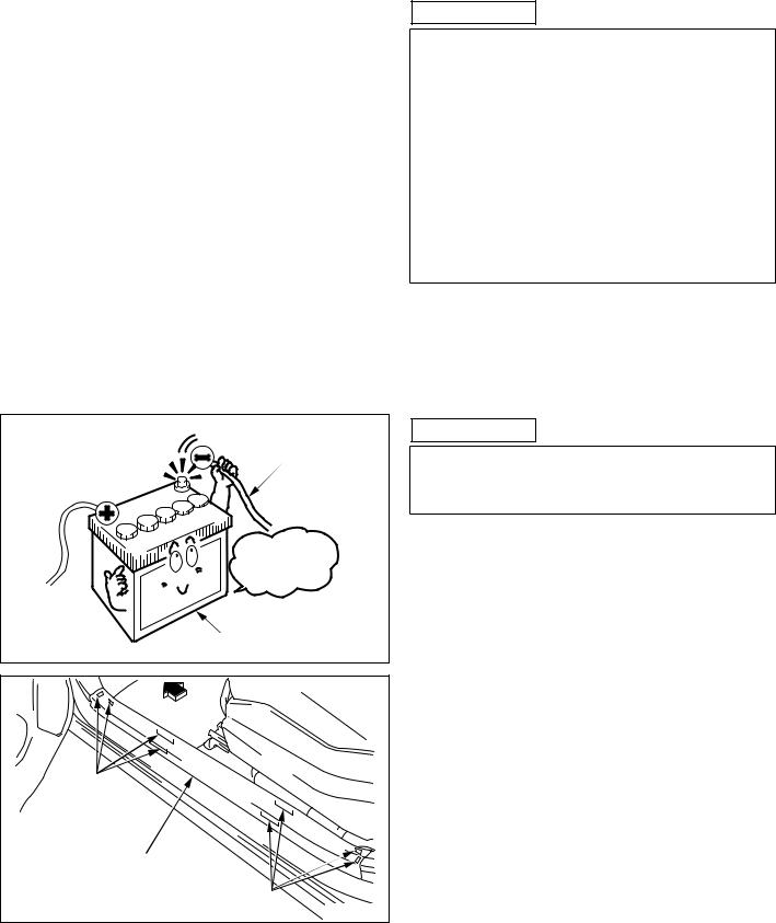
3.Before starting installation, remove the negative terminal of the battery and ensure seat/floor covers are in position.
4.Take care not to scratch any parts of the vehicle.
5.Sort removed bolts and tapping screws into groups so that they can be reassembled correctly.
VEHICLE HARNESS
|
Disconnect |
|
the negative |
|
terminal first. |
|
BATTERY |
|
A009347 |
|
FRONT |
|
HOOKS |
|
SCUFF PLATE (LH) |
|
HOOKS |
|
A029314 |
|
— 1 — |
 CAUTION
First remove the negative terminal of the battery and the vehicle harness connection before installing the equipment.
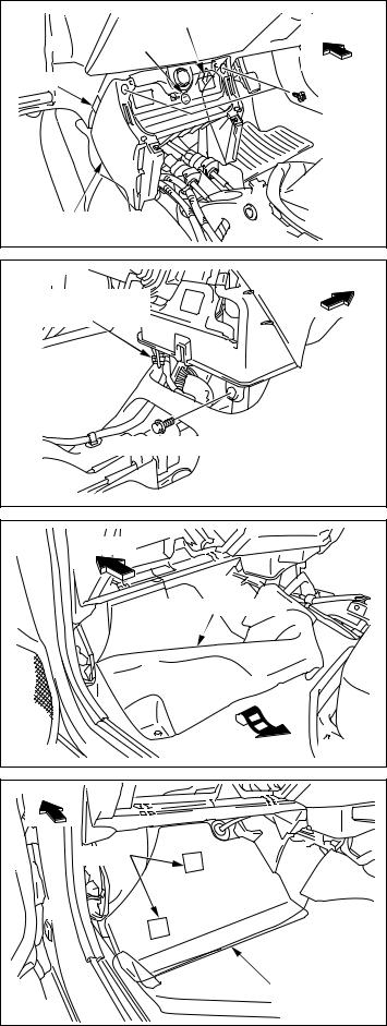
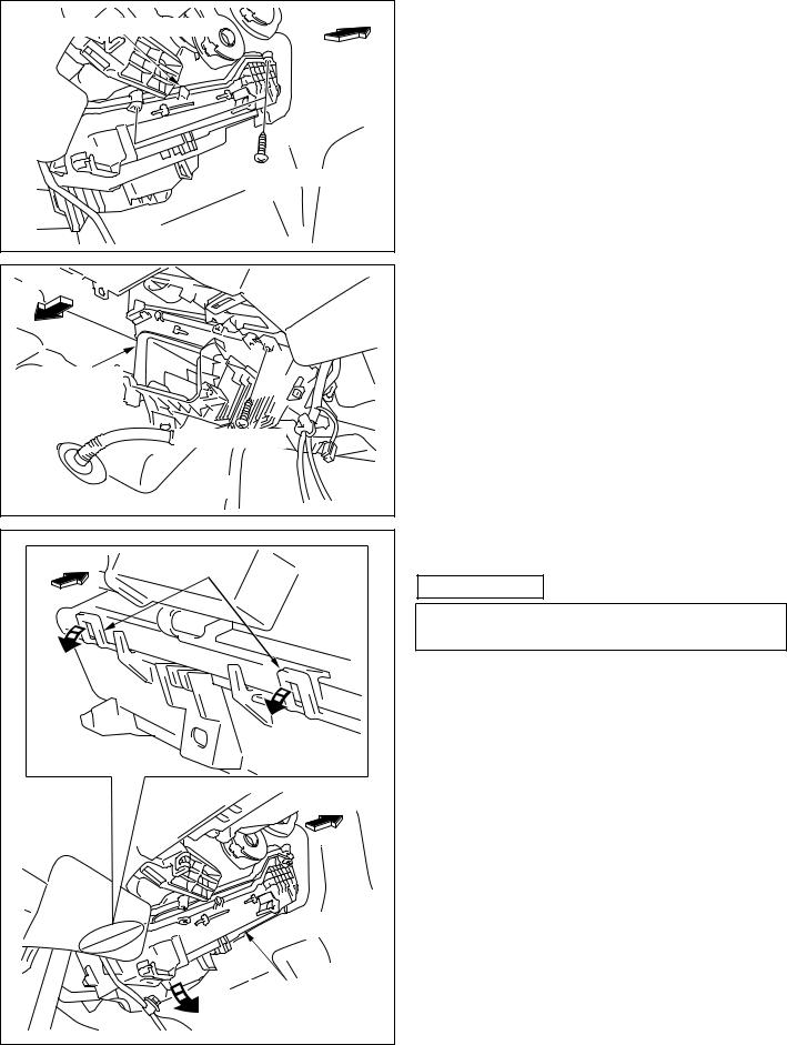
(1)REMOVAL OF ORIGINAL PARTS-1
(a)Scuff plate (LH)
00503437E
|
HOOKS |
|
|
COWL SIDE PANEL (LH) |
|
|
A029268 |
|
|
LEFT SIDE OF THE GLOVE BOX |
|
|
GLOVE BOX |
|
|
LOCK PORTION |
|
|
DAMPER PORTION |
|
|
BOSS |
|
|
BOSS |
NOTE 1, 2 |
|
NOTE 1, 2 |
|
|
GLOVE BOX |
|
|
HOOKS |
|
|
A029176 |
NOTE 3 |
(b) Cowl side panel (LH)
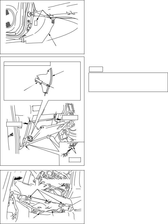
(c) Glove box
NOTE
Remove the glove box in the following order.
1.Press in the sides of the glove box.
2.Bypass the bosses.
3.Lift.
|
FRONT |
||
|
SCREW (REUSE) |
||
|
HOOKS |
||
|
GUIDE |
INSTRUMENT PANEL |
|
|
UNDER COVER (LH) |
A029322 |
|
|
— 2 — |
||
|
00503437E |
VEHICLE WITH INSTRUMENT PANEL UNDER COVER (LH) ONLY [(d)]
(d)Instrument panel under cover (LH)
(e)Screw (for instrument panel)
PASSENGER AIRBAG
CANCEL SWITCH
|
AIRBAG |
|
|
AIRBAG |
CONNECTOR |
|
CONNECTOR CLIP |
|
|
FRONT |
|
|
A029439 |
|
|
INSTRUMENT PANEL |
|
|
HOOK |
UNDER COVER (RH) |
|
GUIDE |
|
|
A029270 |
INSTRUMENT PANEL
LOWER COVER
 FRONT :GUIDE
:HOOK
A029326
— 3 —
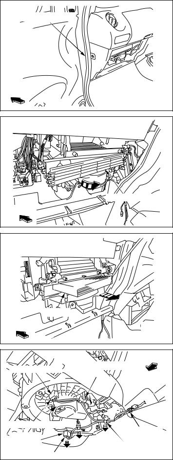
(f)Bolt (for instrument panel)
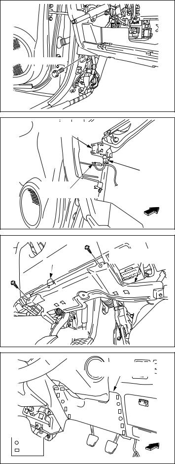
VEHICLE WITH PASSENGER AIRBAG CANCEL SWITCH ONLY [(g)-(h)]
(g)Airbag connector clip
(h)Disconnect the connection of the airbag connector.
VEHICLE WITH INSTRUMENT PANEL UNDER
COVER (RH) ONLY [(i)]
(i)Instrument panel under cover (RH)
VEHICLE WITHOUT KNEE AIRBAG ONLY [(j)]
(j)Instrument panel lower cover
00503437E
|
INSTRUMENT PANEL |
|
LOWER COVER |
|
FRONT |
|
:GUIDE |
|
:HOOK |
|
A029177 |
|
FRONT |
CLIPS |
CENTER CLUSTER |
|
PANEL |
CLIPS
|
CLIPS |
|
|
HOOKS |
A029178 |
|
FRONT |
CLIPS
CLIPS
HEATER CONTROL
PANEL
A029179
— 4 —
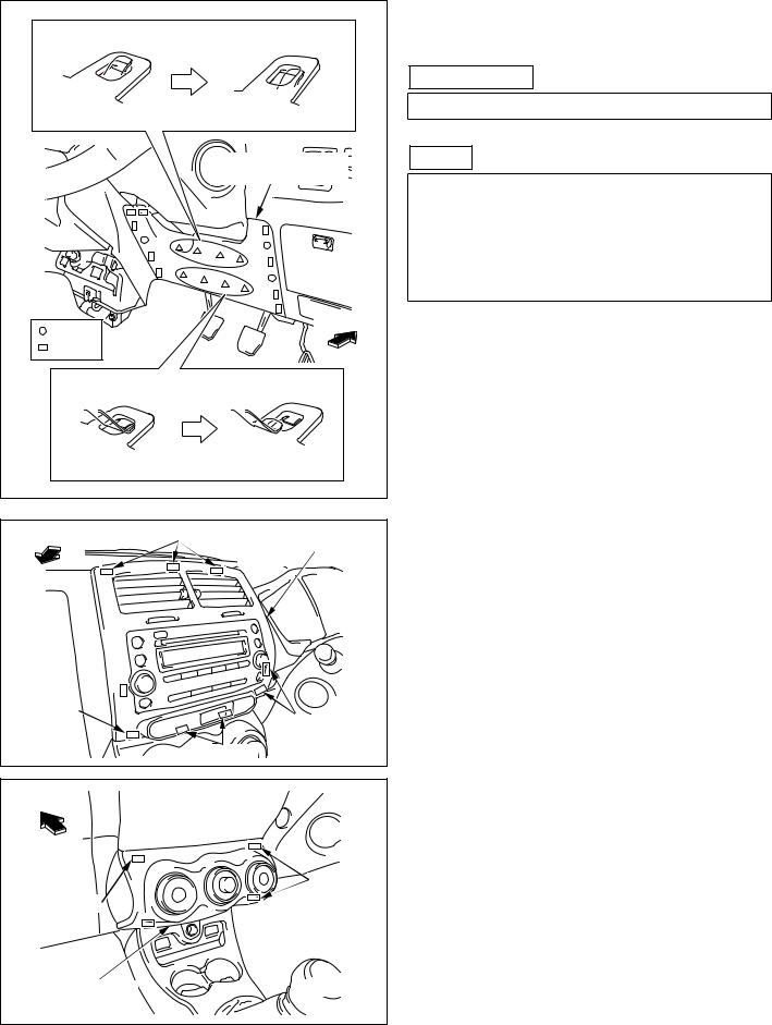
VEHICLE WITH KNEE AIRBAG ONLY [(k)]
(k) Instrument panel lower cover
 CAUTION
Wear a pair of Kevlar gloves before starting work.
NOTE
1.To ease work, insert your hand from under the instrument panel lower cover to the other side of the panel and release the projections on the upper part of the bracket from the holes on the panel.
2.Release the projections one by one.
(l)Center cluster panel
(m) Heater control panel (lift up only)
00503437E

|
FRONT |
|
SHIFT COVER |
|
HOOKS |
|
HOOKS |
|
HOOKS |
|
A029180 |
|
FRONT |
|
|
HOOKS |
|
|
SHIFT PANEL |
|
|
HOOKS |
|
|
CLIPS |
|
|
HOOKS |
A029181 |
|
FRONT |
CONSOLE BOX COVER
(n) Shift cover
(o) Shift panel
(p) Console box cover
NOTE
Disconnect the connector of the console box cover from the vehicle harness.
(q) Console box carpet
(r) Console box
CONSOLE BOX
CONSOLE BOX CARPET
A029182
— 5 —
00503437E
|
GUIDE |
|
|
FRONT |
|
|
CLIP |
|
|
GUIDE |
|
|
CENTER CLUSTER |
|
|
LOWER COVER |
A029183 |
FRONT
VEHICLE
HARNESS CLAMP
BOLT (REUSE)
|
A029184 |
|
|
FRONT |
|
|
FLOOR CARPET (LH) |
|
|
TURN OVER |
A029446 |
|
FRONT |
|
HOOKS |
|
SILENCER MAT (LH) |
|
A029299 |
|
— 6 — |
|
00503437E |
(s) Center cluster lower cover
(t)Bolt (reuse)
(u)Vehicle harness clamp
(v) Floor carpet (LH)
(w) Silencer mat (LH)
WEATHER STRIP (LH)
FRONT
|
A029185 |
|
FILTER COVER |
|
FRONT |
|
A029186 |
(x) Weather strip (LH)
(y) Filter cover
|
(z) |
Filter |
|
FILTER |
|
|
FRONT |
|
|
A029187 |
|
FRONT |
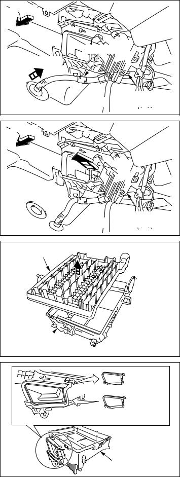
(2) REMOVAL OF ORIGINAL PARTS-2 |
||||
|
(a) Disconnect the vehicle harness from the blower |
|||||
|
VEHICLE HARNESS |
|||||
|
BLOWER MOTOR |
motor. |
||||
|
CLAMP |
|||||
|
(b) Disconnect the vehicle harness from the blower |
|||||
|
resistor. |
|||||
|
(c) Three vehicle harness clamps |
|||||
|
(d) |
Vinyl tape (discard) |
||||
|
VEHICLE HARNESS |
|||||
|
VINYL TAPE |
|||||
|
BLOWER |
(DISCARD) |
||||
|
RESISTOR |
VEHICLE HARNESS |
||||
|
VEHICLE HARNESS |
CLAMPS |
A009590 |
|||
|
— 7 — |
00503437E
FRONT
ORIGINAL FOOT
AIR DUCT (LH) (DISCARD)
HOOKS
HOOK
BLOWER UNIT
|
A001867 |
|
|
BLOWER UNIT |
|
|
UPPER CASE |
|
|
SCREWS |
|
|
BLOWER UNIT |
(REUSE) |
|
LOWER CASE |
A029170 |
|
BLOWER UNIT LEG |
FRONT
BLOWER UNIT
LOWER CASE
A029437
FRONT
SCREW
(REUSE)
SCREW
(REUSE)
BOLT
(REUSE)
BLOWER UNIT
LOWER CASE
A029317
— 8 —
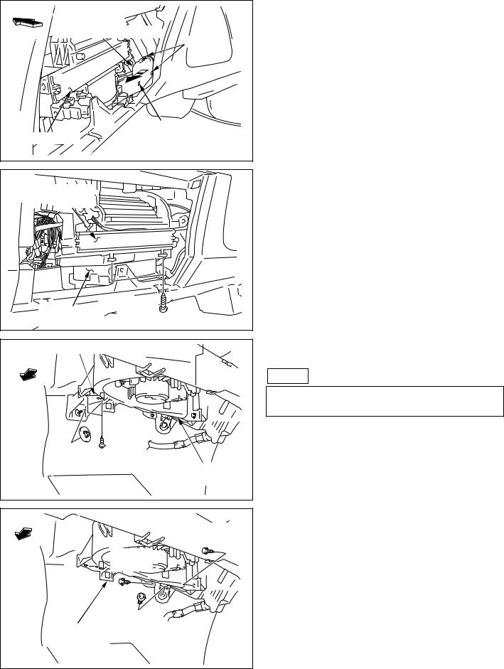
(e) Original foot air duct (LH) (discard)
(f)Two screws (for blower unit lower case)
(g) blower unit leg
NOTE
Pull the blower unit lower case toward the back of the body and remove the blower unit leg.
(h)Two screws (for blower unit lower case)
(i)Bolt (for blower unit lower case)
00503437E
![]()
|
(j) Blower unit lower case |
|||
|
BLOWER UNIT |
|||
|
LOWER CASE |
CAUTION |
||
|
Be careful not to damage the blower unit lower case |
|||
|
when removing the blower unit lower case. |
|||
|
[1] |
|||
|
FRONT |
|||
|
[2] |
|||
|
[3] |
|||
|
BLOWER UNIT |
|||
|
LOWER CASE |
|||
|
A029171 |
|||
|
VEHICLE HARNESS (16-P) |
FRONT |
VEHICLE WITHOUT ORIGINAL AMPLIFIER |
|
|
ONLY [(k) ~ (l)] |
|||
|
(k) |
Vinyl tape (discard) |
||
|
VEHICLE |
(l) |
Vehicle harness clamp |
|
|
HARNESS CLAMP |
|
VINYL TAPE (DISCARD) |
||
|
VEHICLE HARNESS |
||
|
A029473 |
||
|
FRONT |
VEHICLE WITH ORIGINAL AMPLIFIER ONLY |
|
|
[(m) ~ (n)] |
||
|
VEHICLE HARNESS (16-P) |
(m) |
Disconnect the vehicle harness from the original |
|
VEHICLE HARNESS |
amplifier. |
|
|
CLAMP |
(n) |
Vehicle harness clamp |
|
ORIGINAL |
||
|
AMPLIFIER |
||
|
A029284 |
||
|
— 9 — |
||
|
00503437E |
|
(o) |
Original amplifier (discard) |
|
|
FRONT |
||
|
VIEW:A |
||
|
ORIGINAL |
||
|
AMPLIFIER |
||
|
(DISCARD) |
||
|
VIEW:A |
||
|
ORIGINAL |
||
|
AMPLIFIER |
||
|
(DISCARD) |
||
|
[1] |
||
|
ORIGINAL |
||
|
SCREW |
[2] |
|
|
(DISCARD) |
A029283 |
|
(p) |
Airbag ECU |
||
|
FRONT |
|||
|
AIRBAG HARNESS |
|||
|
ORIGINAL |
WARNING |
||
|
1. |
Before starting work always check the cautions |
||
|
BOLTS |
|||
|
(DISCARD) |
and warnings for the SRS airbag system. |
||
|
2. Make sure the ignition switch is OFF (LOCK) |
|||
|
position. |
|||
|
3. Make sure the negative terminal is removed |
|||
|
from the battery. |
|||
|
AIRBAG ECU |
4. If installing airbag sensor assy CTR without |
||
|
disconnecting the negative terminal of the |
|||
|
battery, airbag may open if there is an impact on |
|||
|
FRONT |
it. Make sure that the negative terminal of the |
||
|
battery is disconnected before installation. |
|||
|
5. Wait at least 90 seconds after negative terminal |
|||
|
is disconnected to start installation. |
|||
|
6. Do not disconnect the airbag harness from the |
|||
|
airbag ECU when removing the airbag ECU. |
|||
|
7. Put down the airbag ECU in a way that |
|||
|
minimizes the force on the airbag harness. |
|||
|
8. Do not subject the airbag sensor to any shocks |
|||
|
or force. |
|||
|
AIRBAG ECU |
|||
|
A029324 |
|||
|
— 10 — |
|||
|
00503437E |
|
FRONT |
|
HEATER UNIT LOWER CASE |
|
SCREWS (REUSE) |
|
A001868 |
|
FRONT |
|
|
HEATER UNIT |
|
|
LOWER CASE |
|
|
SCREW (REUSE) |
|
|
A029189 |
|
|
FRONT |
HOOKS |
|
[1] |
|
|
[1] |
FRONT
|
[2] |
HEATER UNIT |
|
|
LOWER CASE |
||
A029447
— 11 —
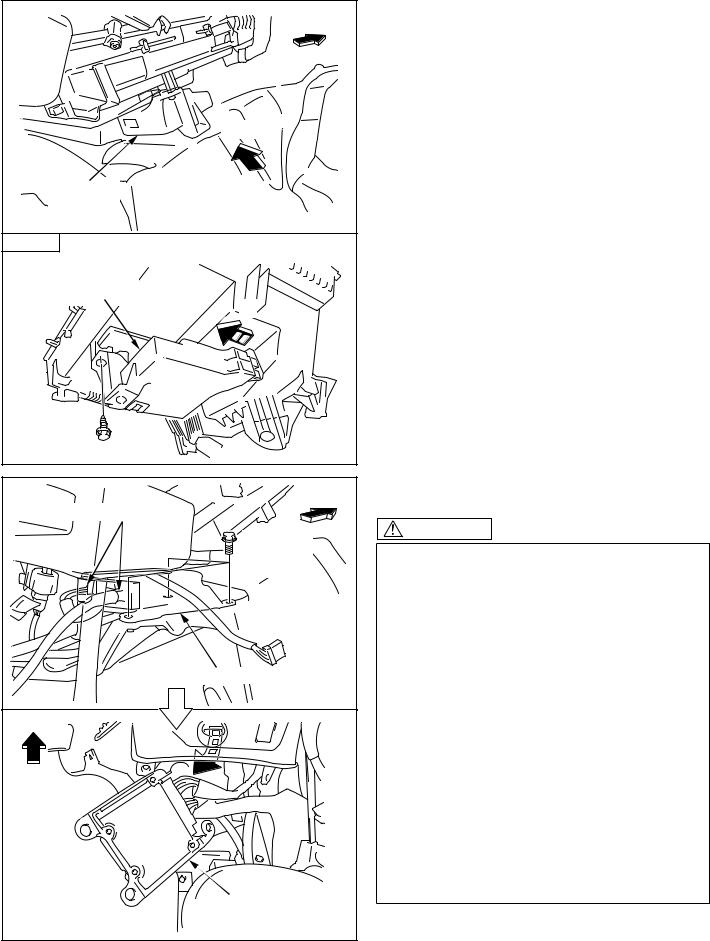
(q) Two screws (for heater unit lower case)
(r)Screw (for heater unit lower case)
(s) Remove the catch of pawl.
 CAUTION
Unhook the catch of pawl and keep as it is. (Do not pull the pawl forcibly because it is easily damaged.)
00503437E
|
FRONT |
|
DRAIN HOSE |
|
PULL OUT |
|
HEATER UNIT |
|
LOWER CASE |
|
A001874 |
|
FRONT |
HEATER UNIT
LOWER CASE
A001875
HEATER UNIT INNER COVER
(DISCARD)
|
HEATER UNIT |
|
|
LOWER CASE |
A001876 |
|
ORIGINAL |
|
|
PACKING |
|
|
(DISCARD) |
|
|
PACKING |
|
|
(INCLUDED IN A/C KIT) |
|
|
HEATER UNIT |
|
|
LOWER CASE |
A009581 |
|
— 12 — |
|
|
00503437E |
(t)Drain hose
(u) Heater unit lower case
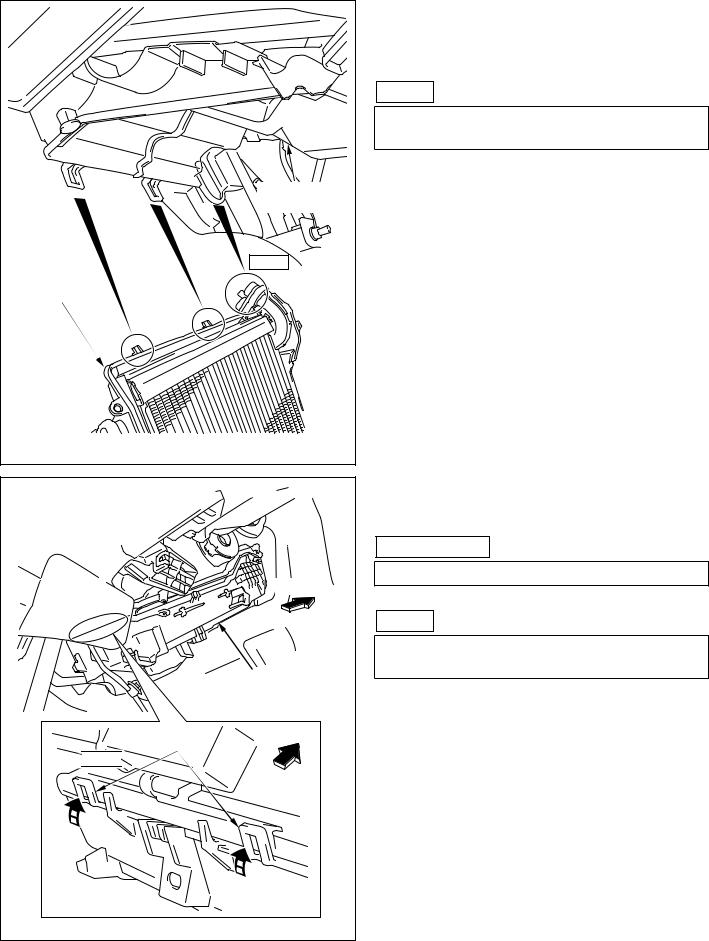
(v) Heater unit inner cover (discard)
(w)Remove and discard a packing from the heater unit lower case.
(x)Attach a packing (included in A/C kit) to the heater unit lower case.
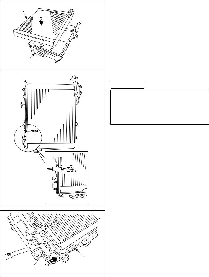
(3) THERMISTOR |
||
|
EVAPORATOR |
(a) Assemble the evaporator to the heater unit lower |
|
|
case. |
||
HEATER UNIT
(b) Assemble the thermistor to the evaporator.
HEATER UNIT LOWER CASE
 CAUTION
1. It shall be only one time to insert the thermistor into the evaporator.
2. When inserting the thermistor into the evaporator again, shift the thermistor one column from the position where one was inserted previously.
|
THERMISTOR |
|
|
34mm |
|
|
50mm |
|
|
EVAPORATOR |
A009577 |
|
(c) Assemble the thermistor connector to the heater |
|
|
unit lower case. |
|
|
HEATER UNIT |
|
|
LOWER CASE |
|
|
THERMISTOR |
|
|
CONNECTOR |
A029474 |
|
— 13 — |
|
|
00503437E |
|
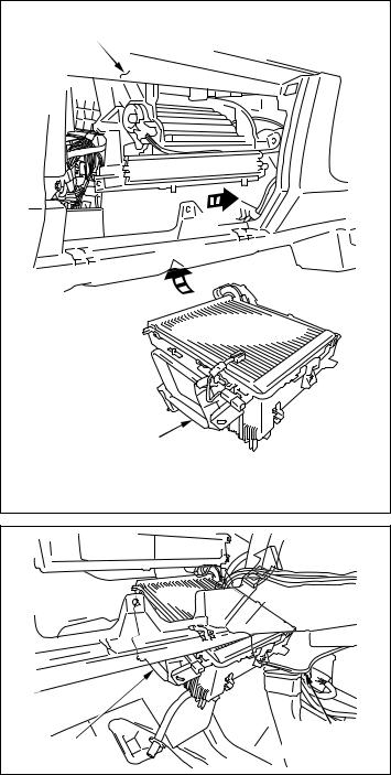
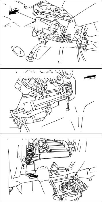
(4) REINSTALLATION OF THE HEATER UNIT |
|
|
INSTRUMENT PANEL |
LOWER CASE |
|
(a) Insert the heater unit lower case into the |
|
|
instrument panel. |
|
|
[2] |
|
|
[1] |
|
|
HEATER UNIT |
|
|
LOWER CASE |
|
|
A029172 |
|
|
(b) Insert the heater unit lower case. |
|
|
INSTRUMENT |
|
|
HEATER UNIT |
PANEL |
|
LOWER CASE |
A009585 |
— 14 —
00503437E
|
A |
HEATER UNIT |
||
|
UPPER CASE |
|||
|
B |
C |
||
|
HEATER UNIT |
C |
NOTE |
|
|
LOWER CASE |
|||
|
B |
|||
|
A |
|||
|
A029271 |
(c)Insert A and B and C on the heater unit lower case into A and B and C on the heater unit upper case respectively.
NOTE
Insert the piping unit of evaporator into the vehicle hole.
(d) Reinstall the heater unit lower case to the heater unit upper case.
 CAUTION
Be sure not to damage the evaporator fins.
FRONT
NOTE
Be careful that the pawl at the vehicle side of a heater unit shall not be locked.
HEATER UNIT
LOWER CASE
FRONT
HOOKS
 NOTE
NOTE 
A029318
— 15 —
00503437E
|
FRONT |
|
HEATER UNIT |
|
LOWER CASE |
|
SCREW (REUSE) |
|
A029285 |
(e)Reinstall the screw for the heater unit lower case of left side.
|
FRONT |
|
HEATER UNIT LOWER CASE |
|
SCREWS (REUSE) |
|
A001868 |
(f)Reinstall two screws for the heater unit lower case of right side.
|
(5) REINSTALLATION OF THE BLOWER UNIT |
||
|
INSTRUMENT |
LOWER CASE |
|
|
PANEL |
||
|
(a) Insert the blower unit lower case into the |
||
|
BLOWER UNIT |
instrument panel. |
|
|
LOWER CASE |
||
|
[2] |
||
|
[1] |
||
|
A029173 |
— 16 —
00503437E
 Loading…
|
Toyota Urban CruiserЭлектронные книги Toyota Urban Cruiser для автомобилистов бесплатно
Руководство по ремонту, эксплуатации и техническому обслуживанию Toyota Urban Cruiser СКАЧАТЬ 291 Мб Руководство по ремонту Toyota Urban Cruiser в фотографиях СКАЧАТЬ 128 Mб Секреты ремонта Toyota Urban Cruiser СКАЧАТЬ 132 Мб Подробная схема электрооборудования Toyota Urban Cruiser СКАЧАТЬ 88 Мб Каталог деталей Toyota Urban Cruiser СКАЧАТЬ 36 Мб Руководство по ремонту двигателя Toyota Urban Cruiser СКАЧАТЬ 53 Мб Руководство по ремонту трансмиссии Toyota Urban Cruiser СКАЧАТЬ 154 Мб Коды неисправностей Toyota Urban Cruiser СКАЧАТЬ 50 Мб Мультимедийное Руководство по тюнингу Toyota Urban Cruiser СКАЧАТЬ 51 Мб Руководства по ремонту Toyota Urban Cruiser
Toyota Urban Cruiser |