- Manuals
- Brands
- Volkswagen Manuals
- Automobile
- Bora 1999
Manuals and User Guides for Volkswagen Bora 1999. We have 2 Volkswagen Bora 1999 manuals available for free PDF download: Service Manual, Workshop Manual
Volkswagen Bora 1999 Service Manual (340 pages)
Brand: Volkswagen
|
Category: Automobile
|
Size: 1.7 MB
Table of Contents
-
ABS ITT Mark 20 IE on Boarddiagnostic (OBD)
2
-
Function
2
-
V.A.G 1551 Scan Tool or Tester VAS 5051
4
-
Identifying Characteristics
5
-
Distinguishing Features
5
-
Distinguishing Features of ABS, ABS/EDL and ABS/EDL/ASR ITT Mark 20 IE Hydraulic Unit
5
-
Technical Data
6
-
Control Module Identification
6
-
Diagnostic Trouble Code (DTC) Memory
6
-
Safety Precautions
7
-
On Board Diagnostic (OBD) with V.A.G 1551 Scan Tool or Tester VAS 5051 (Flow Chart)
8
-
Electrical/Electro Components and Locations
10
-
ABS Hydraulic Unit N55-
10
-
ABS Control Module (W/Edl)-J104-
11
-
ABS/EDL and ABS/EDL/ASR Hydraulic Unit-N55-
12
-
ABS/EDL and ABS/EDL/ASR Control Module-J104-
13
-
Brake Lightswitch-F-
14
-
Data Link Connector (DLC)
14
-
Longitudinal Acceleration Sensor-G251
14
-
ABS Warning Light-K47-
15
-
Warning Light for Brake System-K118-
15
-
ESP Control Lamp-K155-
15
-
Right/Left Front ABS Wheel Speedsensor -G45-/-G47-
16
-
Wheel Hub with Impulse Rotor for Right/Left Front Speed Sensors
16
-
Right/Left Rear ABS Wheel Speed Sensor-G44-/-G46-
18
-
Wheel Hub with Impulse Rotor for Right/Left Rear Speed Sensors
18
-
Diagnostic Trouble Codes (DTC) Displayed by Warning Lights -K14-, -K47- and -K118-
20
-
Warning Lights
20
-
ABS Warning Light -K47-
21
-
ABS Warning Lights -K47- and -K118-
22
-
Electrical Wiring Diagrams, Troubleshooting & Component Locations Binder
22
-
Parking Brake Indicator Light -K14-
23
-
Vehicles with ABS/EDL
23
-
Malfunction: Vehicle Has no EDL Function
23
-
ABS ITT Mk 20 IE on Board Diagnostic (OBD) Program
24
-
Special Tools and Equipment
24
-
Test Requirements
25
-
V.A.G 1551 Scan Tool, Connecting and Selecting Function
26
-
Indicated on Display
26
-
V.A.G-On Board Diagnostic
26
-
Rapid Data Transfer
27
-
Workshop Code
28
-
List of Selectable Functions
30
-
Diagnostic Trouble Code (DTC), Memory
31
-
Work Sequence if a DTC Has Been Detected
32
-
Automatic Test Sequence
33
-
V.A.G — on Board Diagnostic
33
-
Vehicle Diagnosis, Testing and Information System VAS 5051, Connecting and Selecting ABS Control Module
34
-
Select Operating Mode
36
-
Select Vehicle System
36
-
Select Diagnostic Function
37
-
Diagnostic Trouble Code (DTC) Table
38
-
Diagnostic Trouble Code (DTC) Memory, Erasing and Ending Output
59
-
Erasing DTC Memory
59
-
Ending Output
60
-
ABS Control Module, Coding
61
-
Coding Control Module
62
-
Coding Table
63
-
Measured Value Block, Reading
64
-
Observe Following if Test and Measuring Instruments Are Required During a Test Drive
65
-
Read Measured Value Block
66
-
List of Selectable Display Group Numbers
67
-
Test Sequence and Test Tables with Measured Values
69
-
Checking Speed Sensor Allocation
69
-
Display Group Number 001
69
-
For Display Group Number 001 Remember
70
-
Checking Speed Sensor
71
-
Display Group Number 002
71
-
For Display Group Number 002 Remember
72
-
Checking Brake Light Switch for ABS and ABS/EDL Function
73
-
Display Group Number 003
73
-
Checking Data Bus Wiring
75
-
Display Group Number 125
75
-
Output Diagnostic Test Mode (DTM)
77
-
Indicated on V.A.G 1551 Display During Output Diagnostic Test Mode (DTM)
78
-
Output Diagnostic Test Mode
80
-
Indicated on Display (Vehicles with EDL)
92
-
Function Is Unknown or Cannot be Carried out at the Moment
93
-
Basic Setting, Initiating
94
-
Display Group Number 01: Bleeding Hydraulic Unit
95
-
System in Basic Setting
96
-
ABS, ABS/EDL and ABS/EDL/ASR ITT Mark 20 IE, Electrical Check
105
-
Removing Air Cleaner
107
-
Release ABS Control Module (W/Edl) -J104- Connector-Arrow 1- and Pull Off-Arrow 2-
108
-
Connect Test Box V.A.G 1598/21 -1- to Multi-Pin Connector of ABS Control Module (W/Edl) -J104- (-2-)
108
-
Multi-Pin Connector with Contact Assignment
109
-
Contact Assignment of Connectors for Voltage Supply and on Board Diagnostic(OBD) with V.A.G 1551 Scan Tool
109
-
Contact Assignment of Connector T25 Wiring Harness/Abs Control Module (W/Edl) -J104-
109
-
Wiring Connection to Component
110
-
Test Step Overview
112
-
Test Table
114
-
Switch to Measuring Range: Voltage Measurement (20 V =)
115
-
Switch to Measuring Range: Resistance Measurement (2 K)
117
-
Switch to Measuring Range: Voltage Measurement
121
-
Switch to Measuring Range: Resistance Measurement (200)
123
-
Switch to Measuring Range: Resistance Measurement 200
125
-
Functional Check: ABS Warning Light -K47-
126
-
Functional Check: Warning Light for Brake System -K118-
127
-
Functional Check: ABS Hydraulic Pump -V64-
128
-
Switch to Measuring Range: Resistance Measurement (20020)
129
-
Continuation of Test Step 19
130
-
Switch to Measuring Range: Resistance Measurement (200/20)
131
-
Continuation of Test Step 20
132
-
Functional Check: ESP Control Lamp -K155
133
-
Brake Light Switch, Adjusting
134
-
Vehicle up to My 02.00
134
-
Vehicle from My 03.00
135
-
ABS Mark 60 on Board Diagnostic (OBD), Vehicles from My 10.00
136
-
The ESP Is a Further Extension of the Familiar Vehicle Safety Systems
136
-
During this Period a Test Sequence (Self-Check) Is Run in the Control Module for the Following Functions
138
-
Features of 4MOTION
139
-
Special Detail for Bleeding Brake Systems with ABS/EDL
139
-
Arrangement of ABS MARK 60
140
-
Safety Precautions and Fundamental Points Regarding Troubleshooting
142
-
Technical Information
143
-
Troubleshooting with V.A.G 1551 Scan Tool or Tester VAS 5051 on ABS Mark 60 (Flow Chart)
144
-
Electrical/Electro Components and Installing Location
146
-
ABS Control Module (W/Edl) -J104-
147
-
Vehicles with ABS/ESP Only
147
-
Sender for Rotation Rate -G202-
149
-
Vehicles with ABS/EDL/ASR/ESP Only
149
-
Sensor for Transverse Acceleration -G200-
150
-
Longitudinal Acceleration Sensor -G251-
151
-
ESP-Sensor Unit -G419-, Vehicles from 02.02
152
-
Sender 1 for Brake Booster -G201-
154
-
Brake Booster
155
-
Steering Angle Sensor -G85-
155
-
Brake System Vacuum Pump -V192-
156
-
Button for ASR/ESP -E256-
158
-
Warning Light for Brake System -K118-
158
-
ASR/ESP Control Lamp -K155-
158
-
Right/Left Front ABS Wheel Speed Sensor -G45-/-G47-
159
-
Wheel Hub with Rotor for Speed Sensors
159
-
Right/Left Rear Speed Sensor -G44-/-G46-
161
-
Diagnostic Trouble Codes (Dtcs) Displayed by Warning Lights -K47-, -K118- and -K155-
163
-
Warning Lights -K47- and -K118-
165
-
On Board Diagnostic (OBD), Performing
167
-
Test Prerequisites for OBD
167
-
Scan Tool, Connecting
169
-
Connecting VAS 5051
170
-
Selecting Operating Mode
170
-
Selecting Vehicle System
170
-
Selecting Diagnosis Function
170
-
V.A.G 1551 or V.A.G 1552 Scan Tool Vehicle System Tester
171
-
V.A.G 1551/3 or 1551/3A Adapter Cable
171
-
If «Control Module Does Not Answer!» Again Appears
175
-
V.A.G — on Board Diagnosic
177
-
Diagnostic Trouble Code (DTC) Memory, Checking
178
-
Check DTC Memory (Function
179
-
Output Diagnosic Test Mode (DTM)
180
-
Indicated on V.A.G 1551 Display During Output DTM
181
-
Output Diagnosic Test Mode
183
-
ABS Hydraulic Pump-V64 no Longer Runs
185
-
ABS Hydraulic Pump -V64- no Longer Runs
188
-
The ABS Warning Light -K47- Goes out
196
-
Test Sequence
241
-
Vehicle Data Label
242
-
Explanation of the PR. Numbers on Vehicle Data Label
242
-
Location of Optional Equipment Number (PR No.) on Vehicle Data Plate (Arrow)
242
-
Table for ABS, Coding
244
-
With Control Unit Identification Number 1C0 907 379 C/J/L for Vehicles from 10.00
244
-
Table for ABS/EDL/ASR, Coding
245
-
With Control Unit Identification Number 1C0 907 379 D/K for Vehicles from 10.00
245
-
Table for ABS/EDL/ASR/ESP, Coding
246
-
Vehicles with Front Wheel Drive
246
-
With Control Unit Identification Number 1C0 907 379 E/G/M for Vehicles from 10.00
246
-
4MOTION Vehicles
247
-
With Control Unit Identification Number 1C0 907 379 F/H/N
247
-
Overview of Selectable Display Group Numbers
250
-
Checking Brake Light Switch, Brake System Warning Lamp, ABS Warning Lamp and ASR/ESP Warning Lamp
257
-
Checking Steering Angle Sensor, Sensor for Transverse Acceleration and Sender for Rotation Rate
259
-
Checking Sensor for Transverse Acceleration -G200-
261
-
Checking Brake Pressure Sensor
263
-
Display Group Number 005
263
-
Checking Longitudinal Acceleration Sensor -G251-
265
-
Display Group Number 006
265
-
Function 04 «Initiate Basic Setting» Performs Several Functions with ABS Mark 60
272
-
When the ABS Control Module (W/Edl) -J104- Is Replaced, a Zero Compensation Must be Performed for the Following Components
273
-
VAS 5234 Brake Filler and Bleeder Unit
274
-
Basic Setting
275
-
When All 8 Cycles Have Been Performed, this Message Appears on the Display
276
-
Display Group Number 40: Switching off Longitudinal Acceleration Sensor -G251-
277
-
Display Group Number 60: Zero Compensation of Steering Angle Sensor -G85-
279
-
Basic Setting 60 off (4-On)
281
-
Function Is Unknown or Cannot Be-Performed at Moment
281
-
Erase DTC Memory (Function
282
-
Display Group Number 63: Zero Compensation of Sensor for Transverse Acceleration -G200-
283
-
Basic Setting 63 off (4-On)
284
-
End Output (Function
285
-
Display Group Number 66: Zero Compensation for Sender 1 for Brake Booster -G201-
286
-
Display Group Number 69: Zero Compensation of Longitudinal Acceleration Sensor -G251-
289
-
Basic Setting 69 off (4-On)
290
-
Display Group Number 93: Activation of ESP Driving Test
292
-
Basic Setting 93 on (8)
293
-
Login Procedure
295
-
Coding 2
295
-
Electrical Check of Mark 60
296
-
Connect Test Box V.A.G 1598/36 -1- to Multi-Pin Connector of ABS Control Module (W/Edl) -J104- -2-
299
-
Multi-Pin Connector with Contact Assignments
300
-
Contact Assignment of Connectors for Voltage Supply and Self-Diagnosis with the V.A.G 1551 Scan Tool
300
-
Contact Assignment of Connector T47 Wiring Harness/Abs Control Module (W/Edl) -J104-
300
-
Perform Test Step
305
-
Perform Test Step
306
-
Switch to Measuring Range: Resistance Measurement (2 K)
310
-
Switch to Measuring Range: Voltage Measurement (2 V)
314
-
Functional Check: ESP Control Lamp -K155-
318
-
Functional Check: Warning Lamp for ASR/ESP Button -E256-
319
-
Test Table (Test Steps 17-23)
321
-
Switch to Measuring Range: Voltage Measurement (20 V =) in Test Step 17, Resistance Measurement (200) in Test Step 17A
321
-
Continuation of Test Step 17
322
-
Switch to Measuring Range: Resistance Measurement (200/20M)
323
-
Continuation of Test Step 18
326
-
Definitions
334
-
Abs & Asr
334
-
Data Bus Low (High)
334
-
Speed Sensor
334
-
Ebd & Edl
335
-
On Board Diagnostic (OBD)
335
-
Performing on Board Diagnostic (OBD)
335
-
Performing Electrical Check
335
-
No Communication
336
-
Short to Ground
336
-
Short to Positive
337
-
Brake Pressure Release Solenoid -F84-
337
-
Magnetic Coil for Brake Pressure, in Brake Booster, -N247-
337
-
Ebc
337
-
Sender 1 for Brake Booster/Sensor -2- for Brake Pressure -G201-/-G214-
338
-
Program Card Version
338
-
Sporadic
338
-
Infinity
338
-
Forget-Malfunction Counter
339
Advertisement
Volkswagen Bora 1999 Workshop Manual (180 pages)
Brand: Volkswagen
|
Category: Automobile
|
Size: 1.72 MB
Table of Contents
-
Table of Contents
5
-
Technical Data
7
-
1 General Notes on Air Conditioning Systems
7
-
Introduction
7
-
Additional Information
7
-
Basics of Air Conditioning
8
-
Vapour Pressure Table for Refrigerant R134A
9
-
Refrigerant R134A
10
-
Characteristics of Refrigerant R134A
11
-
Refrigerant Machine Oil
13
-
Comfort
15
-
How Air Conditioning Works
15
-
General Safety
16
-
Safety Precautions for When Working on Vehicles with Air Conditioning and When Handling
19
-
Refrigerant R134A
19
-
-
Basics for Working on Refrigerant Circuit
20
-
-
2 General Information on Refrigerant Circuit
23
-
Refrigerant Circuit Components
23
-
Design of Refrigerant Circuit
31
-
Evacuation and Charging Valves for Quick-Release Couplings of Air Conditioner Service Station
31
-
On Refrigerant Circuit
31
-
-
Switch and Sender in Refrigerant Circuit and Related Connections
33
-
Electrical Components Not Installed in Refrigerant Circuit
36
-
Pressures and Temperatures in the Refrigerant Circuit
38
-
Refrigerant Circuit with Expansion Valve
38
-
Refrigerant Circuit with Restrictor and Reservoir
40
-
Test and Measurement Work that Can be Performed Using a Pressure Gauge
42
-
Air Conditioner Service and Recycling Equipment
43
-
Notes to Repairs on Refrigerant Circuit
44
-
-
3 Statutory Texts and Instructions
45
-
Statutes and Regulations
45
-
Recycling and Refuse Law
50
-
Converting R12 Refrigerant Circuits to R134A Refrigerant Circuits and Repairing Them (Retrofitting)
51
-
Maintaining Records on Refrigerant
51
-
-
4 Refrigerant Circuit
52
-
Important Repair Notes on Air Conditioning
52
-
Retrofitting Refrigerant Circuit from R12 Refrigerant to R134A Refrigerant
52
-
-
5 Working with the Air Conditioner Service Station
53
-
Important Notes for Working with the Air Conditioner Service Station
54
-
Connecting Air Conditioner Service Station for Measuring and Checking
54
-
Draining Refrigerant Circuit Using Air Conditioner Service Station
55
-
Evacuating Refrigerant Circuit Using Air Conditioner Service Station
56
-
Charging Refrigerant Circuit Using Air Conditioner Service Station
57
-
Bringing Air Conditioning System into Service after Charging
58
-
Charging Container in Air Conditioner Service Station with Refrigerant
59
-
Draining Air Conditioner Service Station
59
-
-
6 Detecting Leaks in Refrigerant Circuit
61
-
Leak Detection in Refrigerant Circuit Using Compressed Air or Nitrogen
62
-
Searching for Leaks in Refrigerant Circuits Using Leak Detector V.A.G 1796
64
-
Detecting Leaks in Refrigerant Circuit Using Leak Detecting System VAS 6196 or Leak Detecting
65
-
System VAS 6201 or a Later Model
65
-
-
-
7 Clearing Refrigerant Circuit of Contaminants
71
-
Blowing through Refrigerant Circuit with Compressed Air and Nitrogen
71
-
Purging (Cleaning) Refrigerant Circuit with Refrigerant R134A
73
-
-
8 Complaints
128
-
Possible Complaints about Refrigerant Circuit
128
-
Smells from Heater and Air Conditioner Unit
129
-
-
9 Connecting Air Conditioner Service Station
132
-
For Vehicles that Have Connections on both Low-Pressure and High-Pressure Sides of
132
-
Refrigerant Circuit
132
-
-
-
10 Checking Pressures on Vehicles
133
-
Checking Pressures in Refrigerant Circuit (Using Air Conditioner Service Station)
133
-
Checking Systems with a Restrictor and Collector
136
-
Compressor
138
-
-
Checking Systems with an Expansion Valve and Reservoir (with Internally Regulated Air Conditioner Compressor)
141
-
Checking Systems with an Expansion Valve and Reservoir
147
-
Compressor)
147
-
-
Checking Systems with a Restrictor and Reservoir and Air Conditioner Compressor Regulating Valve N280 (with Externally Regulated Air Conditioner Compressor)
149
-
Checking Systems with an Expansion Valve, Receiver and Air Conditioner Compressor
154
-
Regulating Valve N280 (with Externally Regulated Air Conditioner Compressor)
154
-
-
With Expansion Valve, Receiver and Electrical Air Conditioner Compressor
164
-
-
11 Renewing Components
165
-
In the Event of Leaking or Damaged Components (Apart from the Air Conditioner Compressor, Receiver or Reservoir)
166
-
Renewing Air Conditioner Compressor
167
-
Renewing Receiver or Reservoir, and Restrictor
169
-
-
12 Testing Equipment and Tools
171
-
List of Test Equipment, Tools and Materials
171
-
Advertisement
Related Products
-
Volkswagen Bora 2006
-
Volkswagen Bora 1998
-
Volkswagen Bora 2000
-
Volkswagen Bora 2001
-
Volkswagen Bora 2002
-
Volkswagen Bora 2003
-
Volkswagen Bora 2004
-
Volkswagen Bora 2005
-
VOLKSWAGEN BEETLE-1977
-
Volkswagen Passat B5
Volkswagen Categories
Automobile
Automobile Accessories
Car Receiver
Adapter
Engine
More Volkswagen Manuals

а где взять такую же, но для дизельного гольфа до 2001 года?

нету… только 2001-2003
обманул ты меня, мил человек…)))
а учитывая, как мне трудно было это заполучить.)))
я с украины. у нас яндекс-диск даже через VPN не работает.
отослал ссылку другу в ижевск, попросил скачать, он скачал и через вайбер переслал мне.
открываю — а там не оно. печаль(((
я не был уверен что там есть, то что вы ищите. Мне очень жаль, что я не смог вам помочь.
не волнуйтесь, все в порядке, никаких претензий
мне больше хотелось рассказать, как я это заполучил
вдруг попадется книжка по дизельным гольфам 1997-2000, дайте знать, пожалуйста, буду очень признателен

Здраствуйте, поделитесь рабочей ссылкой пожалуйста.
Здравствуйте, все работает

Я езжу на Volkswagen Golf Mk4

Спасибо, буду надеяться, что пригодиться!

блин, могли бы добавить туда и 1,8, 1,8Т, 1,9ТDI, не такие и редкие движки)) но в остальном пригодится
постараюсь найти, как будет результат, напишу в лс

а я прибарахлил, на тот момент были только отрывки и нигде целиком
но авторы молодцы, кое-что есть только тут. деньги они эти заработали
круто, можно пару скринов страниц для примера чтобы было понятно об чем реч
спасибо, теперь вообще гуд, надо качать!)))
Качай) сам очень долго искал, все шляпа какая-то попадалась.

P
r
o
t
e
c
t
e
d
b
y
c
o
p
y
r
i
g
h
t
.
C
o
p
y
i
n
g
f
o
r
p
r
i
v
a
t
e
o
r
c
o
m
m
e
r
c
i
a
l
p
u
r
p
o
s
e
s
,
i
n
p
a
r
t
o
r
i
n
w
h
o
l
e
,
i
s
n
o
t
p
e
r
m
i
t
t
e
d
u
n
l
e
s
s
a
u
t
h
o
r
i
s
e
d
b
y
V
o
l
k
s
w
a
g
e
n
A
G
.
V
o
l
k
s
w
a
g
e
n
A
G
d
o
e
s
n
o
t
g
u
a
r
a
n
t
e
e
o
r
a
c
c
e
p
t
a
n
y
l
i
a
b
i
l
i
t
y
w
i
t
h
r
e
s
p
e
c
t
t
o
t
h
e
c
o
r
r
e
c
t
n
e
s
s
o
f
i
n
f
o
r
m
a
t
i
o
n
i
n
t
h
i
s
d
o
c
u
m
e
n
t
.
C
o
p
y
r
i
g
h
t
b
y
V
o
l
k
s
w
a
g
e
n
A
G
.
Workshop Manual
Bora 1999 ➤ , Bora Variant 1999 ➤ ,
Golf 1992 ➤ , Golf 1998 ➤ ,
Golf 2004 ➤ , Golf Cabrio 1994 ➤ ,
Golf Cabrio 1998 ➤ , Golf GTI 2005 ➤ ,
Golf Plus 2005 ➤ , Golf Variant 1992 ➤ ,
Golf Variant 1998 ➤ ,
Golf Variant 2007 ➤ , Lupo 1999 ➤ ,
Lupo 3L 1999 ➤ ,
New Beetle RSI 2001 ➤ , Passat 1994 ➤ ,
Passat 1997 ➤ , Polo 1995 ➤ ,
Polo 2002 ➤ , Polo Classic 1996 ➤ ,
Polo Variant 1998 ➤ , Sharan 1996 ➤ ,
Touareg 2003 ➤ , Vento 1992 ➤
Wheels and Tyres Guide — Archive
Edition 06.2010
Service
Service Department. Technical Information
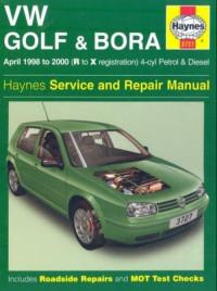
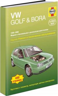
Руководство на английском языке по техническому обслуживанию и ремонту автомобилей Volkswagen Bora и Volkswagen Golf 1998-2000 годов выпуска с бензиновыми и дизельными двигателями.
- Автор: —
- Издательство: Haynes Publishing
- Год издания: 2001
- Страниц: 383
- Формат: PDF
- Размер: 35,8 Mb
Руководство на английском языке по ремонту электрооборудования автомобиля Volkswagen Bora с 2006 года выпуска.
- Автор: —
- Издательство: Volkswagen AG
- Год издания: 2010
- Страниц: 315
- Формат: PDF
- Размер: 8,6 Mb
Руководство по эксплуатации, техническому обслуживанию и ремонту автомобилей Volkswagen Bora и Volkswagen Golf 1998-2000 годов выпуска с бензиновыми и дизельными двигателями.
- Автор: —
- Издательство: Алфамер
- Год издания: —
- Страниц: 400
- Формат: —
- Размер: —
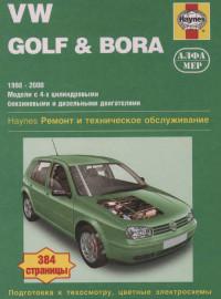
Руководство по техническому обслуживанию и ремонту автомобилей Volkswagen Bora и Volkswagen Golf 1998-2000 годов выпуска с бензиновыми и дизельными двигателями.
- Автор: —
- Издательство: Алфамер Паблишинг
- Год издания: 2004
- Страниц: 372
- Формат: PDF
- Размер: 107,7 Mb
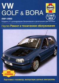
Руководство по эксплуатации, техническому обслуживанию и ремонту автомобилей Volkswagen Bora и Volkswagen Golf 2001-2003 годов выпуска с бензиновыми и дизельными двигателями.
- Автор: А. Легг, П. Гилл
- Издательство: Алфамер
- Год издания: —
- Страниц: 396
- Формат: —
- Размер: —
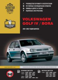
Руководство по эксплуатации и ремонту автомобилей Volkswagen Bora и Volkswagen Golf IV 2001-2003 годов выпуска с бензиновыми и дизельными двигателями.
- Автор: —
- Издательство: Монолит
- Год издания: —
- Страниц: 448
- Формат: —
- Размер: —
Руководство по эксплуатации, техническому обслуживанию и ремонту автомобилей Volkswagen Bora, Volkswagen Jetta и Volkswagen Golf 1997-2005 годов выпуска.
- Автор: —
- Издательство: Мир Автокниг
- Год издания: 2008
- Страниц: 513
- Формат: PDF
- Размер: 464,8 Mb

Руководство по эксплуатации, техобслуживанию и ремонту Volkswagen Bora / Фольксваген Бора
Operation, Maintenance and Repair Manual Volkswagen Bora

- Года выпуска: 1997-2005
Year of release: 1997-2005
Бензиновые двигатели: 1,4 л., 1,6 л., 1,8 л., 2,0 л.
Gasoline engines: 1.4 l., 1.6 l., 1.8 l., 2.0 l.
Дизельные двигатели: 1,9 л.
Diesel Engines: 1.9 l.
- Язык: Русский
Формат: PDF
Размер: 107 Мб
Russian language
Format: PDF
Size: 107 MB
Скачать документацию Volkswagen Bora / Фольксваген Бора
Download the documentation of Volkswagen Bora
для распаковки используйте пароль — avto-ok.info
use the password to unpack — avto-ok.info
———————-
- Язык: Русский
Формат: PDF
Размер: 464 Мб
Russian language
Format: PDF
Size: 464 MB
Скачать документацию Volkswagen Bora / Фольксваген Бора
Download the documentation of Volkswagen Bora
для распаковки используйте пароль — avto-ok.info
use the password to unpack — avto-ok.info
Crash test
P
r
o
t
e
c
t
e
d
b
y
c
o
p
y
r
i
g
h
t
.
C
o
p
y
i
n
g
f
o
r
p
r
i
v
a
t
e
o
r
c
o
m
m
e
r
c
i
a
l
p
u
r
p
o
s
e
s
,
i
n
p
a
r
t
o
r
i
n
w
h
o
l
e
,
i
s
n
o
t
p
e
r
m
i
t
t
e
d
u
n
l
e
s
s
a
u
t
h
o
r
i
s
e
d
b
y
V
o
l
k
s
w
a
g
e
n
A
G
.
V
o
l
k
s
w
a
g
e
n
A
G
d
o
e
s
n
o
t
g
u
a
r
a
n
t
e
e
o
r
a
c
c
e
p
t
a
n
y
l
i
a
b
i
l
i
t
y
w
i
t
h
r
e
s
p
e
c
t
t
o
t
h
e
c
o
r
r
e
c
t
n
e
s
s
o
f
i
n
f
o
r
m
a
t
i
o
n
i
n
t
h
i
s
d
o
c
u
m
e
n
t
.
C
o
p
y
r
i
g
h
t
b
y
V
o
l
k
s
w
a
g
e
n
A
G
.
Workshop Manual
Bora 1999 ➤ , Bora Variant 1999 ➤ ,
CC 2010 ➤ , Eos 2006 ➤ , Golf 1998 ➤ ,
Golf 2004 ➤ , Golf 2009 ➤ ,
Golf Plus 2005 ➤ , Golf Plus 2009 ➤ ,
Golf Variant 1998 ➤ , Lupo 1999 ➤ ,
Lupo 3L 1999 ➤ , Passat 1997 ➤ ,
Passat 2006 ➤ , Passat CC 2009 ➤ ,
Passat Variant 1997 ➤ , Phaeton 2003 ➤ ,
Polo 1995 ➤ , Polo 2002 ➤ ,
Polo 2010 ➤ , Polo KH IN 2010 ➤ ,
Polo Lim IN 2011 ➤ ,
Polo Lim RUS 2011 ➤ , Scirocco 2009 ➤ ,
Sharan 1996 ➤ , Sharan 2011 ➤ ,
Tiguan 2008 ➤ , Touareg 2003 ➤ ,
Touareg 2010 ➤ , Touran 2003 ➤
Electrical System, General Information
Edition 07.2010
Service
Service Department. Technical Information

P
r
o
t
e
c
t
e
d
b
y
c
o
p
y
r
i
g
h
t
.
C
o
p
y
i
n
g
f
o
r
p
r
i
v
a
t
e
o
r
c
o
m
m
e
r
c
i
a
l
p
u
r
p
o
s
e
s
,
i
n
p
a
r
t
o
r
i
n
w
h
o
l
e
,
i
s
n
o
t
p
e
r
m
i
t
t
e
d
u
n
l
e
s
s
a
u
t
h
o
r
i
s
e
d
b
y
V
o
l
k
s
w
a
g
e
n
A
G
.
V
o
l
k
s
w
a
g
e
n
A
G
d
o
e
s
n
o
t
g
u
a
r
a
n
t
e
e
o
r
a
c
c
e
p
t
a
n
y
l
i
a
b
i
l
i
t
y
w
i
t
h
r
e
s
p
e
c
t
t
o
t
h
e
c
o
r
r
e
c
t
n
e
s
s
o
f
i
n
f
o
r
m
a
t
i
o
n
i
n
t
h
i
s
d
o
c
u
m
e
n
t
.
C
o
p
y
r
i
g
h
t
b
y
V
o
l
k
s
w
a
g
e
n
A
G
.
List of Workshop Manual Repair GroupsList of Workshop Manual
Repair GroupsList of Workshop Manual Repair Groups
Re pa ir G ro up
27 — Starter, current supply, CCS
90 — Gauges, instruments
92 — Windscreen wash/wipe system
94 — Lights, bulbs, switches — exterior
96 — Lights, bulbs, switches — interior
97 — Wiring
Technical information should always be available to the foremen and mechanics, because their
careful and constant adherence to the instructions is essential to ensure vehicle road-worthiness and
safety. In addition, the normal basic safety precautions for working on motor vehicles must, as a
matter of course, be observed.
Service
All rights reserved.
No reproduction without prior agreement from publisher.
Copyright © 2010 Volkswagen AG, Wolfsburg K0059101320

P
r
o
t
e
c
t
e
d
b
y
c
o
p
y
r
i
g
h
t
.
C
o
p
y
i
n
g
f
o
r
p
r
i
v
a
t
e
o
r
c
o
m
m
e
r
c
i
a
l
p
u
r
p
o
s
e
s
,
i
n
p
a
r
t
o
r
i
n
w
h
o
l
e
,
i
s
n
o
t
p
e
r
m
i
t
t
e
d
u
n
l
e
s
s
a
u
t
h
o
r
i
s
e
d
b
y
V
o
l
k
s
w
a
g
e
n
A
G
.
V
o
l
k
s
w
a
g
e
n
A
G
d
o
e
s
n
o
t
g
u
a
r
a
n
t
e
e
o
r
a
c
c
e
p
t
a
n
y
l
i
a
b
i
l
i
t
y
w
i
t
h
r
e
s
p
e
c
t
t
o
t
h
e
c
o
r
r
e
c
t
n
e
s
s
o
f
i
n
f
o
r
m
a
t
i
o
n
i
n
t
h
i
s
d
o
c
u
m
e
n
t
.
C
o
p
y
r
i
g
h
t
b
y
V
o
l
k
s
w
a
g
e
n
A
G
.
Contents
27 — Starter, current supply, CCS . . . . . . . . . . . . . . . . . . . . . . . . . . . . . . . . . . . . . . . . 1
1 Battery . . . . . . . . . . . . . . . . . . . . . . . . . . . . . . . . . . . . . . . . . . . . . . . . . . . . . . . . . . . . . . . . 1
1.1 Fundamentals for batteries . . . . . . . . . . . . . . . . . . . . . . . . . . . . . . . . . . . . . . . . . . . . . . . . . . 1
1.2 Types of batteries . . . . . . . . . . . . . . . . . . . . . . . . . . . . . . . . . . . . . . . . . . . . . . . . . . . . . . . . 1
1.3 Warning notices and safety regulations . . . . . . . . . . . . . . . . . . . . . . . . . . . . . . . . . . . . . . . . 2
1.4 Battery terminal connection . . . . . . . . . . . . . . . . . . . . . . . . . . . . . . . . . . . . . . . . . . . . . . . . 4
2 Checking battery . . . . . . . . . . . . . . . . . . . . . . . . . . . . . . . . . . . . . . . . . . . . . . . . . . . . . . . . 5
2.1 Checking the various types of batteries . . . . . . . . . . . . . . . . . . . . . . . . . . . . . . . . . . . . . . . . 5
2.2 Visual check . . . . . . . . . . . . . . . . . . . . . . . . . . . . . . . . . . . . . . . . . . . . . . . . . . . . . . . . . . . . 6
2.3 Checking colour display of magic eye . . . . . . . . . . . . . . . . . . . . . . . . . . . . . . . . . . . . . . . . 6
2.4 Battery tester with printer VAS 5097 A . . . . . . . . . . . . . . . . . . . . . . . . . . . . . . . . . . . . . . . . 8
2.5 Battery tester with printer VAS 6161 . . . . . . . . . . . . . . . . . . . . . . . . . . . . . . . . . . . . . . . . . . 14
2.6 Midtronics MCR340V battery tester only for USA/Canada vehicles . . . . . . . . . . . . . . . . . . 18
2.7 Current draw test . . . . . . . . . . . . . . . . . . . . . . . . . . . . . . . . . . . . . . . . . . . . . . . . . . . . . . . . 22
2.8 Checking no-load voltage of battery on stock and stored vehicles . . . . . . . . . . . . . . . . . . 23
3 Charging battery . . . . . . . . . . . . . . . . . . . . . . . . . . . . . . . . . . . . . . . . . . . . . . . . . . . . . . . . . . 25
3.1 Battery charger VAS 5095 A . . . . . . . . . . . . . . . . . . . . . . . . . . . . . . . . . . . . . . . . . . . . . . . . 25
3.2 Battery charger VAS 5900 . . . . . . . . . . . . . . . . . . . . . . . . . . . . . . . . . . . . . . . . . . . . . . . . . . 30
3.3 Battery charger VAS 5903 . . . . . . . . . . . . . . . . . . . . . . . . . . . . . . . . . . . . . . . . . . . . . . . . . . 41
3.4 Battery charger VAS 5906 . . . . . . . . . . . . . . . . . . . . . . . . . . . . . . . . . . . . . . . . . . . . . . . . . . 53
3.5 Midtronics INC 940 battery charger only for USA/Canada . . . . . . . . . . . . . . . . . . . . . . . . . . 55
3.6 Solar panel VAS 6102A . . . . . . . . . . . . . . . . . . . . . . . . . . . . . . . . . . . . . . . . . . . . . . . . . . . . 59
3.7 Totally discharged batteries . . . . . . . . . . . . . . . . . . . . . . . . . . . . . . . . . . . . . . . . . . . . . . . . 59
4 Cruise control system (CCS) . . . . . . . . . . . . . . . . . . . . . . . . . . . . . . . . . . . . . . . . . . . . . . . . 61
4.1 Activating and deactivating cruise control system (CCS) . . . . . . . . . . . . . . . . . . . . . . . . . . 61
90 — Gauges, instruments . . . . . . . . . . . . . . . . . . . . . . . . . . . . . . . . . . . . . . . . . . . . . . 62
92 — Windscreen wash/wipe system . . . . . . . . . . . . . . . . . . . . . . . . . . . . . . . . . . . . . . 63
1 Washer fluid line hose couplings . . . . . . . . . . . . . . . . . . . . . . . . . . . . . . . . . . . . . . . . . . . . 63
1.1 Windscreen and rear window washer system . . . . . . . . . . . . . . . . . . . . . . . . . . . . . . . . . . 63
1.2 Headlight washer system . . . . . . . . . . . . . . . . . . . . . . . . . . . . . . . . . . . . . . . . . . . . . . . . . . 64
2 Hose repair . . . . . . . . . . . . . . . . . . . . . . . . . . . . . . . . . . . . . . . . . . . . . . . . . . . . . . . . . . . . . . 65
2.1 General description . . . . . . . . . . . . . . . . . . . . . . . . . . . . . . . . . . . . . . . . . . . . . . . . . . . . . . 65
2.2 Repairing smooth pipe . . . . . . . . . . . . . . . . . . . . . . . . . . . . . . . . . . . . . . . . . . . . . . . . . . . . 65
2.3 Repairing corrugated pipe . . . . . . . . . . . . . . . . . . . . . . . . . . . . . . . . . . . . . . . . . . . . . . . . . . 65
3 Distinguishing features of jointless wiper blades . . . . . . . . . . . . . . . . . . . . . . . . . . . . . . . . 67
94 — Lights, bulbs, switches — exterior . . . . . . . . . . . . . . . . . . . . . . . . . . . . . . . . . . . . . . 68
1 Operation and safety notes for gas discharge bulbs . . . . . . . . . . . . . . . . . . . . . . . . . . . . . . 68
96 — Lights, bulbs, switches — interior . . . . . . . . . . . . . . . . . . . . . . . . . . . . . . . . . . . . . . 71
1 12 V socket . . . . . . . . . . . . . . . . . . . . . . . . . . . . . . . . . . . . . . . . . . . . . . . . . . . . . . . . . . . . 71
1.1 Removing and installing 12 V socket . . . . . . . . . . . . . . . . . . . . . . . . . . . . . . . . . . . . . . . . 71
1.2 Removing and installing socket illumination bulb L42 . . . . . . . . . . . . . . . . . . . . . . . . . . . . 71
2 Cigarette lighter U1 . . . . . . . . . . . . . . . . . . . . . . . . . . . . . . . . . . . . . . . . . . . . . . . . . . . . . . 72
2.1 General description . . . . . . . . . . . . . . . . . . . . . . . . . . . . . . . . . . . . . . . . . . . . . . . . . . . . . . 72
2.2 Assembly overview . . . . . . . . . . . . . . . . . . . . . . . . . . . . . . . . . . . . . . . . . . . . . . . . . . . . . . . . 73
2.3 Removing and installing cigarette lighter socket . . . . . . . . . . . . . . . . . . . . . . . . . . . . . . . . 74
2.4 Removing and installing cigarette lighter illumination bulb L28 . . . . . . . . . . . . . . . . . . . . . . 76
97 — Wiring . . . . . . . . . . . . . . . . . . . . . . . . . . . . . . . . . . . . . . . . . . . . . . . . . . . . . . . . . . 78
Bora 1999 ➤ , Bora Variant 1999 ➤ , CC 2010 ➤ , Eos 2006 ➤ , Golf 199 …
Electrical System, General Information — Edition 07.2010
Contents i

P
r
o
t
e
c
t
e
d
b
y
c
o
p
y
r
i
g
h
t
.
C
o
p
y
i
n
g
f
o
r
p
r
i
v
a
t
e
o
r
c
o
m
m
e
r
c
i
a
l
p
u
r
p
o
s
e
s
,
i
n
p
a
r
t
o
r
i
n
w
h
o
l
e
,
i
s
n
o
t
p
e
r
m
i
t
t
e
d
u
n
l
e
s
s
a
u
t
h
o
r
i
s
e
d
b
y
V
o
l
k
s
w
a
g
e
n
A
G
.
V
o
l
k
s
w
a
g
e
n
A
G
d
o
e
s
n
o
t
g
u
a
r
a
n
t
e
e
o
r
a
c
c
e
p
t
a
n
y
l
i
a
b
i
l
i
t
y
w
i
t
h
r
e
s
p
e
c
t
t
o
t
h
e
c
o
r
r
e
c
t
n
e
s
s
o
f
i
n
f
o
r
m
a
t
i
o
n
i
n
t
h
i
s
d
o
c
u
m
e
n
t
.
C
o
p
y
r
i
g
h
t
b
y
V
o
l
k
s
w
a
g
e
n
A
G
.
1 Vehicle diagnostic, testing and information systems . . . . . . . . . . . . . . . . . . . . . . . . . . . . . . 78
1.1 Connecting vehicle diagnostic tester . . . . . . . . . . . . . . . . . . . . . . . . . . . . . . . . . . . . . . . . . . 78
1.2 Connecting vehicle diagnostic tester Golf Model Year 1998 — 2003 . . . . . . . . . . . . . . . . . . 80
2 Repairing wiring harnesses and connectors . . . . . . . . . . . . . . . . . . . . . . . . . . . . . . . . . . . . 81
2.1 Wiring harness repair set . . . . . . . . . . . . . . . . . . . . . . . . . . . . . . . . . . . . . . . . . . . . . . . . . . 81
2.2 Tool descriptions . . . . . . . . . . . . . . . . . . . . . . . . . . . . . . . . . . . . . . . . . . . . . . . . . . . . . . . . 82
2.3 General notes concerning repairs to vehicle electrical system . . . . . . . . . . . . . . . . . . . . . . 85
2.4 Repairs to wiring harnesses . . . . . . . . . . . . . . . . . . . . . . . . . . . . . . . . . . . . . . . . . . . . . . . . 87
2.5 Repairs to contact housings and connectors . . . . . . . . . . . . . . . . . . . . . . . . . . . . . . . . . . . . 97
2.6 Releasing and dismantling contact housings . . . . . . . . . . . . . . . . . . . . . . . . . . . . . . . . . . . . 102
3 Contact surface cleaning set VAS 6410 . . . . . . . . . . . . . . . . . . . . . . . . . . . . . . . . . . . . . . 108
3.1 Using contact surface cleaning set VAS 6410 . . . . . . . . . . . . . . . . . . . . . . . . . . . . . . . . . . 108
4 Renewing Lambda probe . . . . . . . . . . . . . . . . . . . . . . . . . . . . . . . . . . . . . . . . . . . . . . . . . . 115
4.1 Renewing LSF Lambda probe (4-pin) . . . . . . . . . . . . . . . . . . . . . . . . . . . . . . . . . . . . . . . . 115
4.2 Renewing LSU Lambda probe (6-pin) . . . . . . . . . . . . . . . . . . . . . . . . . . . . . . . . . . . . . . . . 116
4.3 Types of protective tube on uniform Lambda probes . . . . . . . . . . . . . . . . . . . . . . . . . . . . . . 117
Bora 1999 ➤ , Bora Variant 1999 ➤ , CC 2010 ➤ , Eos 2006 ➤ , Golf 199 …
Electrical System, General Information — Edition 07.2010
ii Contents
P
r
o
t
e
c
t
e
d
b
y
c
o
p
y
r
i
g
h
t
.
C
o
p
y
i
n
g
f
o
r
p
r
i
v
a
t
e
o
r
c
o
m
m
e
r
c
i
a
l
p
u
r
p
o
s
e
s
,
i
n
p
a
r
t
o
r
i
n
w
h
o
l
e
,
i
s
n
o
t
p
e
r
m
i
t
t
e
d
u
n
l
e
s
s
a
u
t
h
o
r
i
s
e
d
b
y
V
o
l
k
s
w
a
g
e
n
A
G
.
V
o
l
k
s
w
a
g
e
n
A
G
d
o
e
s
n
o
t
g
u
a
r
a
n
t
e
e
o
r
a
c
c
e
p
t
a
n
y
l
i
a
b
i
l
i
t
y
w
i
t
h
r
e
s
p
e
c
t
t
o
t
h
e
c
o
r
r
e
c
t
n
e
s
s
o
f
i
n
f
o
r
m
a
t
i
o
n
i
n
t
h
i
s
d
o
c
u
m
e
n
t
.
C
o
p
y
r
i
g
h
t
b
y
V
o
l
k
s
w
a
g
e
n
A
G
.
27 – Starter, current supply, CCS
1 Battery
WARNING
Danger of injury! Observe warning notices and safety regula‐
tions ⇒ page 2 !
Caution
To prevent damage to the battery and vehicle, the following
should be observed concerning types of battery ⇒ page 1 .
1.1 Fundamentals for batteries
To ensure long use of the battery, the battery must be checked,
serviced and maintained according to the specifications in this
manual.
Apart from supplying energy for starting the engine, the battery
has other tasks: it acts as a buffer and supplies electrical energy
to the complete electrical onboard supply of the vehicle.
1.2 Types of batteries
General notes
Caution
The description for the following batteries is for maintenance-
free batteries. No stickers may be removed and do not replen‐
ish with distilled water. Only perform a visual check. Refer to
chapter, Checking battery ⇒ page 5 .
1.2.1 Battery with magic eye
This is a maintenance-free battery with liquid electrolyte (wet bat‐
tery).
Caution
No stickers may be removed and do not replenish with distilled
water. Only perform a visual check. Refer to chapter, Checking
battery ⇒ page 5 .
WARNING
Batteries where the magic eye is colourless or light yellow must
not be checked or charged. Do not slave/jump start the vehicle!
Danger of explosion when checking and charging or slave/
jump starting.
These batteries must be renewed.
Bora 1999 ➤ , Bora Variant 1999 ➤ , CC 2010 ➤ , Eos 2006 ➤ , Golf 199 …
Electrical System, General Information — Edition 07.2010
1. Battery 1
P
r
o
t
e
c
t
e
d
b
y
c
o
p
y
r
i
g
h
t
.
C
o
p
y
i
n
g
f
o
r
p
r
i
v
a
t
e
o
r
c
o
m
m
e
r
c
i
a
l
p
u
r
p
o
s
e
s
,
i
n
p
a
r
t
o
r
i
n
w
h
o
l
e
,
i
s
n
o
t
p
e
r
m
i
t
t
e
d
u
n
l
e
s
s
a
u
t
h
o
r
i
s
e
d
b
y
V
o
l
k
s
w
a
g
e
n
A
G
.
V
o
l
k
s
w
a
g
e
n
A
G
d
o
e
s
n
o
t
g
u
a
r
a
n
t
e
e
o
r
a
c
c
e
p
t
a
n
y
l
i
a
b
i
l
i
t
y
w
i
t
h
r
e
s
p
e
c
t
t
o
t
h
e
c
o
r
r
e
c
t
n
e
s
s
o
f
i
n
f
o
r
m
a
t
i
o
n
i
n
t
h
i
s
d
o
c
u
m
e
n
t
.
C
o
p
y
r
i
g
h
t
b
y
V
o
l
k
s
w
a
g
e
n
A
G
.
This battery is equipped with a magic eye. The magic eye pro‐
vides information concerning the level of the electrolyte and the
charge state of the battery via a coloured display. Checking colour
display of the magic eye ⇒ page 6
1.2.2 Absorbent glass mat battery
Maintenance-free battery with a contained electrolyte and no
magic eye.
Lead-acid battery where the electrolyte is contained within a mi‐
croscopic glass mat (AGM). The battery is sealed and fitted with
valves.
AGM is the abbreviation for absorbent glass mat.
Due to containment of the electrolyte, this type of battery may not
have a magic eye. Absorbent glass mat batteries are identified by
the abbreviation AGM on the battery.
Note
Always replace an absorbent glass mat battery with another ab‐
sorbent glass mat battery.
1.3 Warning notices and safety regulations
1.3.1 Dangers when handling vehicle batter‐
ies
Recognition and avoidance of dangers
Batteries can be dangerous. These dangers can be avoided when
the warnings on the battery, in the operating manual and in ELSA
are observed.
Bora 1999 ➤ , Bora Variant 1999 ➤ , CC 2010 ➤ , Eos 2006 ➤ , Golf 199 …
Electrical System, General Information — Edition 07.2010
2 Rep. gr.27 — Starter, current supply, CCS
P
r
o
t
e
c
t
e
d
b
y
c
o
p
y
r
i
g
h
t
.
C
o
p
y
i
n
g
f
o
r
p
r
i
v
a
t
e
o
r
c
o
m
m
e
r
c
i
a
l
p
u
r
p
o
s
e
s
,
i
n
p
a
r
t
o
r
i
n
w
h
o
l
e
,
i
s
n
o
t
p
e
r
m
i
t
t
e
d
u
n
l
e
s
s
a
u
t
h
o
r
i
s
e
d
b
y
V
o
l
k
s
w
a
g
e
n
A
G
.
V
o
l
k
s
w
a
g
e
n
A
G
d
o
e
s
n
o
t
g
u
a
r
a
n
t
e
e
o
r
a
c
c
e
p
t
a
n
y
l
i
a
b
i
l
i
t
y
w
i
t
h
r
e
s
p
e
c
t
t
o
t
h
e
c
o
r
r
e
c
t
n
e
s
s
o
f
i
n
f
o
r
m
a
t
i
o
n
i
n
t
h
i
s
d
o
c
u
m
e
n
t
.
C
o
p
y
r
i
g
h
t
b
y
V
o
l
k
s
w
a
g
e
n
A
G
.
WARNING
♦ Untrained personnel e.g. apprentices, trainees etc. may
only work on batteries when supervised by a vehicle me‐
chanic/foreman or vehicle electrician/foreman.
♦ Acid is highly corrosive. There is a considerable danger of
acid burns if personnel do not handle batteries correctly.
Therefore suitable measures must be taken to ensure that
equipment/solutions etc. are available to neutralize acid
burns. A suitable solution is: e.g. a soap solution.
♦ If electrolyte leaks from a battery it may cause skin burns
or acid corrosion and rusting on the vehicle. This may
damage safety relevant components on the vehicle.
♦ The gas which forms when charging and the gas which
may escape through vent valves is explosive. In extreme
cases a battery may explode if the battery is not handled
correctly.
♦ Batteries must be renewed where the magic eye is col‐
ourless or light yellow. They must not be checked or
charged and do not slave/jump start. Danger of explosion
when checking and charging or slave/jump starting.
♦ It is prohibited to cause sparks through grinding, welding,
cutting operations and use naked lights in the vicinity of
batteries. Smoking is also prohibited. Sparks generated
by electrostatic charging must also be avoided. Always
touch the vehicle body before touching the battery.
♦ Only work on batteries in well ventilated and suitable
rooms.
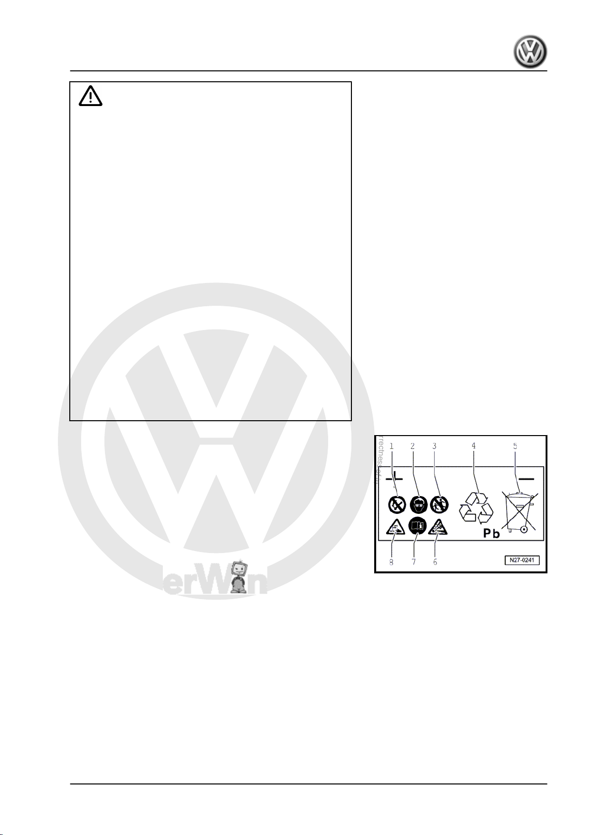
1.3.2 Safety markings on battery
Safety markings on battery
1. — Fires, sparks, naked flames and smoking are prohibited when
handling batteries. Avoid sparks as well as electrostatic discharge
when working with cables and electrical units. Avoid short circuits.
Therefore never lay a tool on a battery.
2. — Wear eye protection before commencing work on battery.
3. — Keep children away from acid and batteries.
4. — Disposal: old batteries are classed as hazardous waste. They
may only be disposed of through a suitable collection centre and
only in accordance with respective legislation.
5. — Never dispose of old batteries in household waste system!
6. — There is a danger of an explosion when working with batteries.
A highly explosive gas is produced when batteries are charged.
7. — Always follow instructions on battery, in ELSA «Electrical Sys‐
tem, General Information» and in owner’s manual.
8. — Battery acid is very caustic; therefore wear eye protection and
gloves when working with batteries. Do not tilt battery. Acid can
leak out of the gas vents of some batteries.
Bora 1999 ➤ , Bora Variant 1999 ➤ , CC 2010 ➤ , Eos 2006 ➤ , Golf 199 …
Electrical System, General Information — Edition 07.2010
1. Battery 3
P
r
o
t
e
c
t
e
d
b
y
c
o
p
y
r
i
g
h
t
.
C
o
p
y
i
n
g
f
o
r
p
r
i
v
a
t
e
o
r
c
o
m
m
e
r
c
i
a
l
p
u
r
p
o
s
e
s
,
i
n
p
a
r
t
o
r
i
n
w
h
o
l
e
,
i
s
n
o
t
p
e
r
m
i
t
t
e
d
u
n
l
e
s
s
a
u
t
h
o
r
i
s
e
d
b
y
V
o
l
k
s
w
a
g
e
n
A
G
.
V
o
l
k
s
w
a
g
e
n
A
G
d
o
e
s
n
o
t
g
u
a
r
a
n
t
e
e
o
r
a
c
c
e
p
t
a
n
y
l
i
a
b
i
l
i
t
y
w
i
t
h
r
e
s
p
e
c
t
t
o
t
h
e
c
o
r
r
e
c
t
n
e
s
s
o
f
i
n
f
o
r
m
a
t
i
o
n
i
n
t
h
i
s
d
o
c
u
m
e
n
t
.
C
o
p
y
r
i
g
h
t
b
y
V
o
l
k
s
w
a
g
e
n
A
G
.
1.4 Battery terminal connection
Caution
To prevent damage to the battery clamps and battery termi‐
nals, the following should be observed:
♦ The battery clamps should only be fitted by hand and with‐
out using force.
♦ Battery terminals should not be coated with grease.
♦ The battery clamps should be fitted so that the battery ter‐
minal is either flush with the clamp or protruding from it.
♦ Once the battery clamps have been tightened to the speci‐
fied torque, the threaded connections should not be tight‐
ened any further.
Bora 1999 ➤ , Bora Variant 1999 ➤ , CC 2010 ➤ , Eos 2006 ➤ , Golf 199 …
Electrical System, General Information — Edition 07.2010
4 Rep. gr.27 — Starter, current supply, CCS
P
r
o
t
e
c
t
e
d
b
y
c
o
p
y
r
i
g
h
t
.
C
o
p
y
i
n
g
f
o
r
p
r
i
v
a
t
e
o
r
c
o
m
m
e
r
c
i
a
l
p
u
r
p
o
s
e
s
,
i
n
p
a
r
t
o
r
i
n
w
h
o
l
e
,
i
s
n
o
t
p
e
r
m
i
t
t
e
d
u
n
l
e
s
s
a
u
t
h
o
r
i
s
e
d
b
y
V
o
l
k
s
w
a
g
e
n
A
G
.
V
o
l
k
s
w
a
g
e
n
A
G
d
o
e
s
n
o
t
g
u
a
r
a
n
t
e
e
o
r
a
c
c
e
p
t
a
n
y
l
i
a
b
i
l
i
t
y
w
i
t
h
r
e
s
p
e
c
t
t
o
t
h
e
c
o
r
r
e
c
t
n
e
s
s
o
f
i
n
f
o
r
m
a
t
i
o
n
i
n
t
h
i
s
d
o
c
u
m
e
n
t
.
C
o
p
y
r
i
g
h
t
b
y
V
o
l
k
s
w
a
g
e
n
A
G
.
2 Checking battery
WARNING
Danger of injury! Observe warning notices and safety regula‐
tions ⇒ page 2 !
Caution
To prevent damage to the battery and vehicle, the following
should be observed concerning types of battery ⇒ page 1 .
2.1 Checking the various types of batteries
2.1.1 Checking battery with magic eye
WARNING
Danger of injury! Observe warning notices and safety regula‐
tions ⇒ page 2 !
Carry out procedure in sequence as follows:
1. Visual check ⇒ page 6
2. Check colour display of „3-colour“ magic eye ⇒ page 6
or „2-colour“ magic eye ⇒ page 7 .
WARNING
Batteries where the magic eye is colourless or light yellow must
not be checked or charged. Do not slave/jump start the vehicle!
Danger of explosion when checking and charging or slave/
jump starting
These batteries must be renewed.
3. Perform a battery load test using battery tester with printer
-VAS 5097 A- ⇒ page 9 .
– Battery test with battery tester with printer -VAS 6161-
⇒ page 14 .
4. Depending on the result of the battery test, „perform current
draw test“ ⇒ page 22 .
2.1.2 Absorbent glass mat battery
Carry out procedure in sequence as follows:
1. Visual check ⇒ page 6
2. Perform a battery load test using battery tester with printer
-VAS 5097 A- ⇒ page 9 .
– Battery load test with battery tester with printer -VAS 6161-
⇒ page 14
Bora 1999 ➤ , Bora Variant 1999 ➤ , CC 2010 ➤ , Eos 2006 ➤ , Golf 199 …
Electrical System, General Information — Edition 07.2010
2. Checking battery 5
P
r
o
t
e
c
t
e
d
b
y
c
o
p
y
r
i
g
h
t
.
C
o
p
y
i
n
g
f
o
r
p
r
i
v
a
t
e
o
r
c
o
m
m
e
r
c
i
a
l
p
u
r
p
o
s
e
s
,
i
n
p
a
r
t
o
r
i
n
w
h
o
l
e
,
i
s
n
o
t
p
e
r
m
i
t
t
e
d
u
n
l
e
s
s
a
u
t
h
o
r
i
s
e
d
b
y
V
o
l
k
s
w
a
g
e
n
A
G
.
V
o
l
k
s
w
a
g
e
n
A
G
d
o
e
s
n
o
t
g
u
a
r
a
n
t
e
e
o
r
a
c
c
e
p
t
a
n
y
l
i
a
b
i
l
i
t
y
w
i
t
h
r
e
s
p
e
c
t
t
o
t
h
e
c
o
r
r
e
c
t
n
e
s
s
o
f
i
n
f
o
r
m
a
t
i
o
n
i
n
t
h
i
s
d
o
c
u
m
e
n
t
.
C
o
p
y
r
i
g
h
t
b
y
V
o
l
k
s
w
a
g
e
n
A
G
.
3. Depending on the result of the battery test, „perform current
draw test“ ⇒ page 22 .
2.2 Visual check
WARNING
Danger of injury! Observe warning notices and safety regula‐
tions ⇒ page 2 !
It is essential to visually inspect the external condition, to check
the terminals and to ensure proper attachment of the battery be‐
fore performing extensive tests.
Caution
♦ The battery will be damaged if the battery is not secured
correctly.
♦ Vibrations shorten the life of the battery, there is a danger
of an explosion, the cell plates may be damaged and the
clamping bracket may damage the battery housing.
♦ Check battery is securely seated, if necessary tighten se‐
curing bolt to specified torque.
Performing this test establishes:
♦ If battery housing is damaged Electrolyte can leak out if the
housing is damaged. If battery acid leaks out, serious damage
to the vehicle could be caused. Treat components affected by
leaked battery acid immediately with acid neutraliser or a soap
solution.
♦ Check whether the battery terminals (battery wire connec‐
tions) are damaged. The necessary contact on the battery
clamps cannot be guaranteed if the battery terminals are dam‐
aged. When connecting the battery clamps, tighten the battery
clamps to torque specified in this workshop manual „Electrical
system“ for the respective vehicle. If the battery clamps are
not correctly seated and tightened, the wiring may burn. Which
will cause malfunctions in the electrical system. Therefore it
can no longer be guaranteed that the vehicle will function cor‐
rectly.
2.3 Checking colour display of magic eye
2.3.1 Checking colour display of „3-colour“
magic eye
WARNING
Danger of injury! Observe warning notices and safety regula‐
tions ⇒ page 2 !
Bora 1999 ➤ , Bora Variant 1999 ➤ , CC 2010 ➤ , Eos 2006 ➤ , Golf 199 …
Electrical System, General Information — Edition 07.2010
6 Rep. gr.27 — Starter, current supply, CCS
P
r
o
t
e
c
t
e
d
b
y
c
o
p
y
r
i
g
h
t
.
C
o
p
y
i
n
g
f
o
r
p
r
i
v
a
t
e
o
r
c
o
m
m
e
r
c
i
a
l
p
u
r
p
o
s
e
s
,
i
n
p
a
r
t
o
r
i
n
w
h
o
l
e
,
i
s
n
o
t
p
e
r
m
i
t
t
e
d
u
n
l
e
s
s
a
u
t
h
o
r
i
s
e
d
b
y
V
o
l
k
s
w
a
g
e
n
A
G
.
V
o
l
k
s
w
a
g
e
n
A
G
d
o
e
s
n
o
t
g
u
a
r
a
n
t
e
e
o
r
a
c
c
e
p
t
a
n
y
l
i
a
b
i
l
i
t
y
w
i
t
h
r
e
s
p
e
c
t
t
o
t
h
e
c
o
r
r
e
c
t
n
e
s
s
o
f
i
n
f
o
r
m
a
t
i
o
n
i
n
t
h
i
s
d
o
c
u
m
e
n
t
.
C
o
p
y
r
i
g
h
t
b
y
V
o
l
k
s
w
a
g
e
n
A
G
.
General information on magic eye:
Applies for all batteries with „1J0“, „7N0“ and „3B0“ indexes in
original equipment and for all replacement batteries 191 915 105
AB and from „000 915 105 AX“ index.
The magic eye provides information concerning electrolyte level
and the charge state of the battery.
Before carrying out a visual check, tap the magic eye lightly and
carefully using the handle of a screwdriver. The air bubbles, which
can influence the display, will dissipate when doing this. The col‐
our display of the magic eye will therefore be more accurate.
Note
♦
Air bubbles can form below the magic eye particularly when
the battery is being charged, including during normal vehicle
operation. These distort the colour displayed by the magic eye.
♦
Because the magic eye is located in only one cell, the display
applies only to this cell. An exact determination of the battery
condition is only possible through a battery load test
⇒ page 9 or a battery test ⇒ page 14 .
♦
The magic eye can be located at various positions on the bat‐
tery.
Three different colour displays are possible:
♦ »Green«, battery is charged sufficiently.
♦ »Black«, battery partly discharged, charge state < 65 % or
completely discharged
♦ »Colourless or light yellow«, battery must be renewed.
WARNING
Batteries where the magic eye is colourless or light yellow must
not be checked or charged. Do not slave/jump start the vehicle!
Danger of explosion when checking and charging or slave/
jump starting
These batteries must be renewed.
2.3.2 Checking colour display of „2-colour“
magic eye
WARNING
Danger of injury! Observe warning notices and safety regula‐
tions ⇒ page 2 !
Bora 1999 ➤ , Bora Variant 1999 ➤ , CC 2010 ➤ , Eos 2006 ➤ , Golf 199 …
Electrical System, General Information — Edition 07.2010
2. Checking battery 7
P
r
o
t
e
c
t
e
d
b
y
c
o
p
y
r
i
g
h
t
.
C
o
p
y
i
n
g
f
o
r
p
r
i
v
a
t
e
o
r
c
o
m
m
e
r
c
i
a
l
p
u
r
p
o
s
e
s
,
i
n
p
a
r
t
o
r
i
n
w
h
o
l
e
,
i
s
n
o
t
p
e
r
m
i
t
t
e
d
u
n
l
e
s
s
a
u
t
h
o
r
i
s
e
d
b
y
V
o
l
k
s
w
a
g
e
n
A
G
.
V
o
l
k
s
w
a
g
e
n
A
G
d
o
e
s
n
o
t
g
u
a
r
a
n
t
e
e
o
r
a
c
c
e
p
t
a
n
y
l
i
a
b
i
l
i
t
y
w
i
t
h
r
e
s
p
e
c
t
t
o
t
h
e
c
o
r
r
e
c
t
n
e
s
s
o
f
i
n
f
o
r
m
a
t
i
o
n
i
n
t
h
i
s
d
o
c
u
m
e
n
t
.
C
o
p
y
r
i
g
h
t
b
y
V
o
l
k
s
w
a
g
e
n
A
G
.
General information on magic eye:
For batteries from „5K0“ index in original equipment and for re‐
placement batteries 191 915 105 AC from „000 915 105 DX“
index, the »green« colour display for charge state display has
been discontinued. The introduction of the new colour display will
take place gradually, i.e. there will be a transition period for both
displays. In the future, the only remaining colours will be »black«
or »colourless or light yellow«.
The magic eye provides information concerning the electrolyte
level of the battery.
The charge state of the battery can no longer be read from the
magic eye, a battery load test must be carried out for this
⇒ page 9
Before carrying out a visual check, tap the magic eye lightly and
carefully using the handle of a screwdriver. The air bubbles, which
can influence the display, will dissipate when doing this. The col‐
our display of the magic eye will therefore be more accurate.
Note
♦
Air bubbles can form below the magic eye particularly when
the battery is being charged, including during normal vehicle
operation. These distort the colour displayed by the magic eye.
♦
Because the magic eye is located in only one cell, the display
applies only to this cell. An exact determination of the battery
condition is only possible through a battery load test
⇒ page 9 .
♦
The magic eye can be located at various positions on the bat‐
tery.
Three different colour displays are possible:
♦ »Black«, electrolyte level is OK.
♦ »Colourless or light yellow«, electrolyte level too low. The bat‐
tery must be renewed.
WARNING
Batteries where the magic eye is colourless or light yellow must
not be checked or charged. Do not slave/jump start the vehicle!
Danger of explosion when checking and charging or slave/
jump starting
These batteries must be renewed.
2.4 Battery tester with printer -VAS 5097 A-
WARNING
Danger of injury! Observe warning notices and safety regula‐
tions ⇒ page 2 !
It is not necessary to remove or disconnect battery when using
battery tester with printer -VAS 5097 A- .
Battery tester with printer -VAS 5097 A- can be used to test 12 V
starter batteries.
Bora 1999 ➤ , Bora Variant 1999 ➤ , CC 2010 ➤ , Eos 2006 ➤ , Golf 199 …
Electrical System, General Information — Edition 07.2010
8 Rep. gr.27 — Starter, current supply, CCS
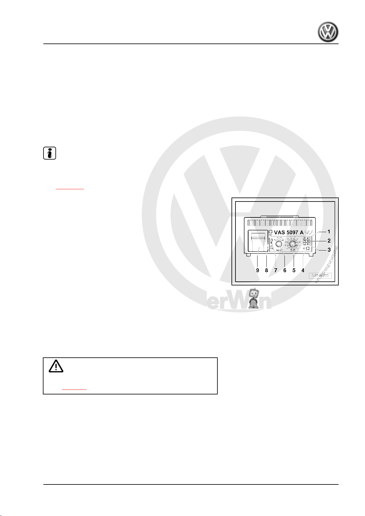
P
r
o
t
e
c
t
e
d
b
y
c
o
p
y
r
i
g
h
t
.
C
o
p
y
i
n
g
f
o
r
p
r
i
v
a
t
e
o
r
c
o
m
m
e
r
c
i
a
l
p
u
r
p
o
s
e
s
,
i
n
p
a
r
t
o
r
i
n
w
h
o
l
e
,
i
s
n
o
t
p
e
r
m
i
t
t
e
d
u
n
l
e
s
s
a
u
t
h
o
r
i
s
e
d
b
y
V
o
l
k
s
w
a
g
e
n
A
G
.
V
o
l
k
s
w
a
g
e
n
A
G
d
o
e
s
n
o
t
g
u
a
r
a
n
t
e
e
o
r
a
c
c
e
p
t
a
n
y
l
i
a
b
i
l
i
t
y
w
i
t
h
r
e
s
p
e
c
t
t
o
t
h
e
c
o
r
r
e
c
t
n
e
s
s
o
f
i
n
f
o
r
m
a
t
i
o
n
i
n
t
h
i
s
d
o
c
u
m
e
n
t
.
C
o
p
y
r
i
g
h
t
b
y
V
o
l
k
s
w
a
g
e
n
A
G
.
♦ 80 — 520 A low-temperature test current according to DIN
(Deutsche Industrie Norm (German Industrial Standard))
1)
♦ 95 — 574 A cold cranking current according to IEC (Interna‐
tional Engineering Consortium)
♦ 136 — 855 A cold cranking current according to EN/ SAE (Eu‐
ropean Norm/Standard of Automotive Engineers)
1) Batteries with cold cranking current higher than 499 A according to DIN (e.g.
520 A, 580 A or 600 A) can be temporarily tested using setting for 499 A according
to DIN.
For test purposes the battery is loaded with a current which is
similar to the starting current required to start the vehicle. The
battery is assessed on this loading and the result is printed out.
Note
Observe the ⇒ instruction manual of Battery tester with printer —
VAS 5097 A- or the sticker ⇒ Brief instructions for battery tester
with printer -VAS 5097 A- on the unit or table: Cold cranking cur‐
rent ⇒ page 11 .
2.4.1 Description of battery tester with printer
-VAS 5097 A-
Battery tester with printer -VAS 5097 A-
1 — Green LED, „unit operating“
2 — Red LED, „unit reverse-polarity connected“
3 — Red LED, „battery cannot be tested“, recharge battery.
4 — Start button
5 — Cold cranking current selection switch
6 — ON/OFF and functions switch
7 — Selection switch (battery tester to pick-off point on battery/
external test point in engine compartment)
8 — Paper feed button
9 — Printer
2.4.2 Performing battery load test using bat‐
tery tester with printer -VAS 5097 A-
WARNING
Danger of injury! Observe warning notices and safety regula‐
tions ⇒ page 2 !
Special tools and workshop equipment required
Bora 1999 ➤ , Bora Variant 1999 ➤ , CC 2010 ➤ , Eos 2006 ➤ , Golf 199 …
Electrical System, General Information — Edition 07.2010
2. Checking battery 9
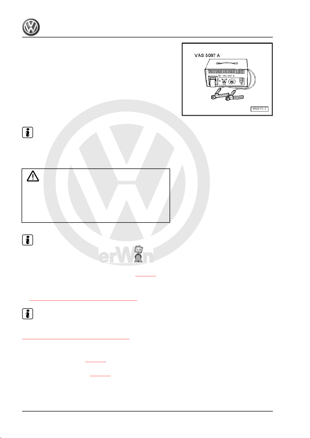
P
r
o
t
e
c
t
e
d
b
y
c
o
p
y
r
i
g
h
t
.
C
o
p
y
i
n
g
f
o
r
p
r
i
v
a
t
e
o
r
c
o
m
m
e
r
c
i
a
l
p
u
r
p
o
s
e
s
,
i
n
p
a
r
t
o
r
i
n
w
h
o
l
e
,
i
s
n
o
t
p
e
r
m
i
t
t
e
d
u
n
l
e
s
s
a
u
t
h
o
r
i
s
e
d
b
y
V
o
l
k
s
w
a
g
e
n
A
G
.
V
o
l
k
s
w
a
g
e
n
A
G
d
o
e
s
n
o
t
g
u
a
r
a
n
t
e
e
o
r
a
c
c
e
p
t
a
n
y
l
i
a
b
i
l
i
t
y
w
i
t
h
r
e
s
p
e
c
t
t
o
t
h
e
c
o
r
r
e
c
t
n
e
s
s
o
f
i
n
f
o
r
m
a
t
i
o
n
i
n
t
h
i
s
d
o
c
u
m
e
n
t
.
C
o
p
y
r
i
g
h
t
b
y
V
o
l
k
s
w
a
g
e
n
A
G
.
♦ Battery tester with printer -VAS 5097 A-
Note
Observe technical product information TPI 2012182 for battery
tester with printer -VAS 5097 A- .
Performing battery load test:
WARNING
Batteries where the magic eye is colourless or light yellow must
not be checked or charged. Do not slave/jump start the vehicle!
Danger of explosion when checking and charging or slave/
jump starting
These batteries must be renewed.
Note
The battery must have a temperature of at least 10 °C.
– Switch off ignition and all electrical consumers.
– Check magic eye on batteries with magic eye ⇒ page 5 .
– Check low-temperature test current in amperes (A) according
to DIN from indications on battery or set setting range on bat‐
tery tester with printer -VAS 5097 A- according to table
⇒ „2.4.3 Table: cold cranking current“, page 11 .
Note
If the battery values are shown in IEC or EN/SAE instead of DIN
then convert figures using table
⇒ „2.4.3 Table: cold cranking current“, page 11 or using table
on unit.
– Select low-temperature test current via low-temperature test
current selection switch ⇒ page 9 .
– Select measuring range 80 — 379 A or 380 — 499 A with ON/
OFF and functions switch ⇒ page 9 .
Bora 1999 ➤ , Bora Variant 1999 ➤ , CC 2010 ➤ , Eos 2006 ➤ , Golf 199 …
Electrical System, General Information — Edition 07.2010
10 Rep. gr.27 — Starter, current supply, CCS
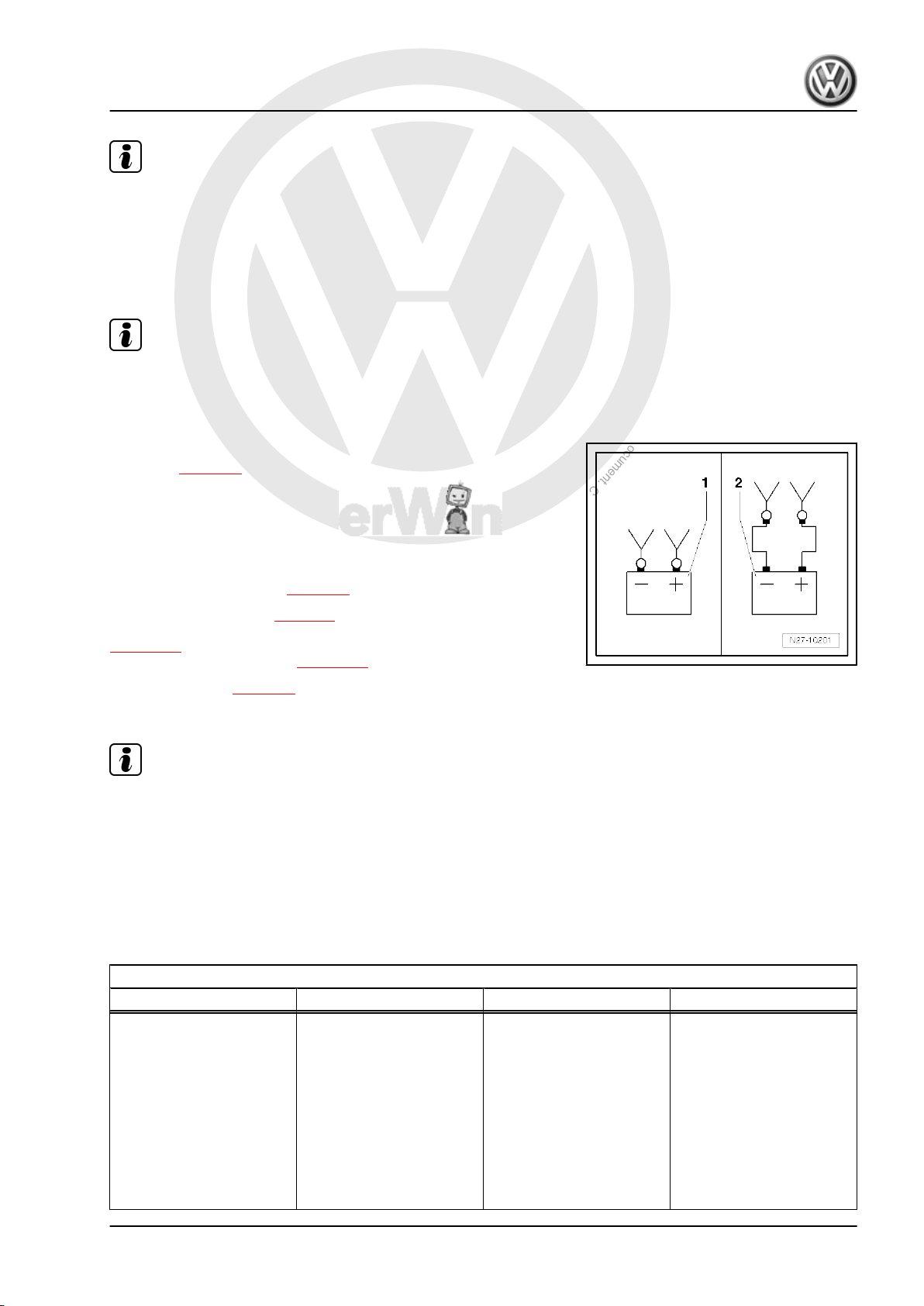
P
r
o
t
e
c
t
e
d
b
y
c
o
p
y
r
i
g
h
t
.
C
o
p
y
i
n
g
f
o
r
p
r
i
v
a
t
e
o
r
c
o
m
m
e
r
c
i
a
l
p
u
r
p
o
s
e
s
,
i
n
p
a
r
t
o
r
i
n
w
h
o
l
e
,
i
s
n
o
t
p
e
r
m
i
t
t
e
d
u
n
l
e
s
s
a
u
t
h
o
r
i
s
e
d
b
y
V
o
l
k
s
w
a
g
e
n
A
G
.
V
o
l
k
s
w
a
g
e
n
A
G
d
o
e
s
n
o
t
g
u
a
r
a
n
t
e
e
o
r
a
c
c
e
p
t
a
n
y
l
i
a
b
i
l
i
t
y
w
i
t
h
r
e
s
p
e
c
t
t
o
t
h
e
c
o
r
r
e
c
t
n
e
s
s
o
f
i
n
f
o
r
m
a
t
i
o
n
i
n
t
h
i
s
d
o
c
u
m
e
n
t
.
C
o
p
y
r
i
g
h
t
b
y
V
o
l
k
s
w
a
g
e
n
A
G
.
Note
Batteries with cold cranking current higher than 499 A according
to DIN (e.g. 520 A, 580 A or 600 A) can be temporarily tested
using setting for 499 A according to DIN.
– Connect red terminal „+“ of tester to positive terminal.
– Connect black terminal „-“ of tester to negative terminal.
Note
♦
Ensure test clamps have a good contact!
♦
Observe technical product information TPI 2012182 for battery
tester with printer -VAS 5097 A- .
– Select point of connection of test terminals with selection
switch ⇒ page 9 .
1 — Connected directly to battery
2 — Connected to external test points in engine compartment
– Check that the figures given on the battery are correct for the
settings on the battery tester.
– Press start test button ⇒ page 9 .
The green LED lights up ⇒ page 9 . The test program runs through
automatically. The test result is printed out by the printer
⇒ page 12 . If the unit does not start (LED does not light up, no
print out), recharge battery ⇒ page 25 and test again.
– Switch off unit ⇒ page 9 .
– Remove test terminals.
Note
♦
The test is completed after about 20 seconds.
♦
The result of the test is printed out by the printer.
♦
Perform test once only. Repeating the test falsifies the result.
♦
The tester requires approx. 30 minutes to cool down before it
is ready for the next test.
2.4.3 Table: cold cranking current
Cold cranking current in A
EN/ SAE IEC ⇒ DIN
136 – 17 95 – 124 ⇒ 80 – 104
178 – 219 125 – 154 ⇒ 105 – 129
220 – 261 155 – 184 ⇒ 130 – 154
262 – 303 185 – 214 ⇒ 155 – 179
304 – 345 215 – 244 ⇒ 180 – 204
346 – 387 245 – 274 ⇒ 204 – 229
388 – 429 275 – 304 ⇒ 230 – 254
430 – 471 305 – 334 ⇒ 255 – 279
472 – 513 335 – 364 ⇒ 280 – 304
Bora 1999 ➤ , Bora Variant 1999 ➤ , CC 2010 ➤ , Eos 2006 ➤ , Golf 199 …
Electrical System, General Information — Edition 07.2010
2. Checking battery 11
P
r
o
t
e
c
t
e
d
b
y
c
o
p
y
r
i
g
h
t
.
C
o
p
y
i
n
g
f
o
r
p
r
i
v
a
t
e
o
r
c
o
m
m
e
r
c
i
a
l
p
u
r
p
o
s
e
s
,
i
n
p
a
r
t
o
r
i
n
w
h
o
l
e
,
i
s
n
o
t
p
e
r
m
i
t
t
e
d
u
n
l
e
s
s
a
u
t
h
o
r
i
s
e
d
b
y
V
o
l
k
s
w
a
g
e
n
A
G
.
V
o
l
k
s
w
a
g
e
n
A
G
d
o
e
s
n
o
t
g
u
a
r
a
n
t
e
e
o
r
a
c
c
e
p
t
a
n
y
l
i
a
b
i
l
i
t
y
w
i
t
h
r
e
s
p
e
c
t
t
o
t
h
e
c
o
r
r
e
c
t
n
e
s
s
o
f
i
n
f
o
r
m
a
t
i
o
n
i
n
t
h
i
s
d
o
c
u
m
e
n
t
.
C
o
p
y
r
i
g
h
t
b
y
V
o
l
k
s
w
a
g
e
n
A
G
.
Cold cranking current in A
EN/ SAE IEC ⇒ DIN
514 – 555 365 – 394 ⇒ 305 –329
556 – 597 395 – 424 ⇒ 330 – 354
598 – 639 425 – 454 ⇒ 355 – 379
640 – 657 455 – 464 ⇒ 380 – 389
658 – 675 465 – 474 ⇒ 390 – 399
676 – 693 475 – 484 ⇒ 400 – 409
694 – 711 485 – 494 ⇒ 410 – 419
712 – 729 495 – 504 ⇒ 420 – 429
730 – 747 505 – 514 ⇒ 430 – 439
748 – 765 515 – 524 ⇒ 440 – 449
766 – 783 525 – 534 ⇒ 450 – 459
784 – 801 535 – 544 ⇒ 460 – 469
802 – 819 545 – 554 ⇒ 470 – 479
820 – 837 555 – 564 ⇒ 480 – 489
838 – 855 565 – 574 ⇒
490 – 499
2)
1)
2)
1)
Batteries with cold cranking current higher than 499 A according to DIN (e.g. 520 A, 580 A or 600 A) can be temporarily tested using
setting for 499 A according to DIN.
2.4.4 Evaluating test result of battery load test
Because of the high load on the battery during this test (a high
current flows) the battery voltage drops.
♦ If the battery is OK, the voltage value drops only to the mini‐
mum voltage.
♦ If the battery is defective or has a low charge, the battery volt‐
age quickly drops below the minimum voltage.
♦ After the test is completed, this low voltage value remains over
a longer period, and the voltage increases very slowly again.
♦ Perform test once only. Repeating the test falsifies the result.
♦ The tester requires approx. 30 minutes to cool down before
carrying out another test or testing another battery to ensure
the results are not falsified.
Bora 1999 ➤ , Bora Variant 1999 ➤ , CC 2010 ➤ , Eos 2006 ➤ , Golf 199 …
Electrical System, General Information — Edition 07.2010
12 Rep. gr.27 — Starter, current supply, CCS
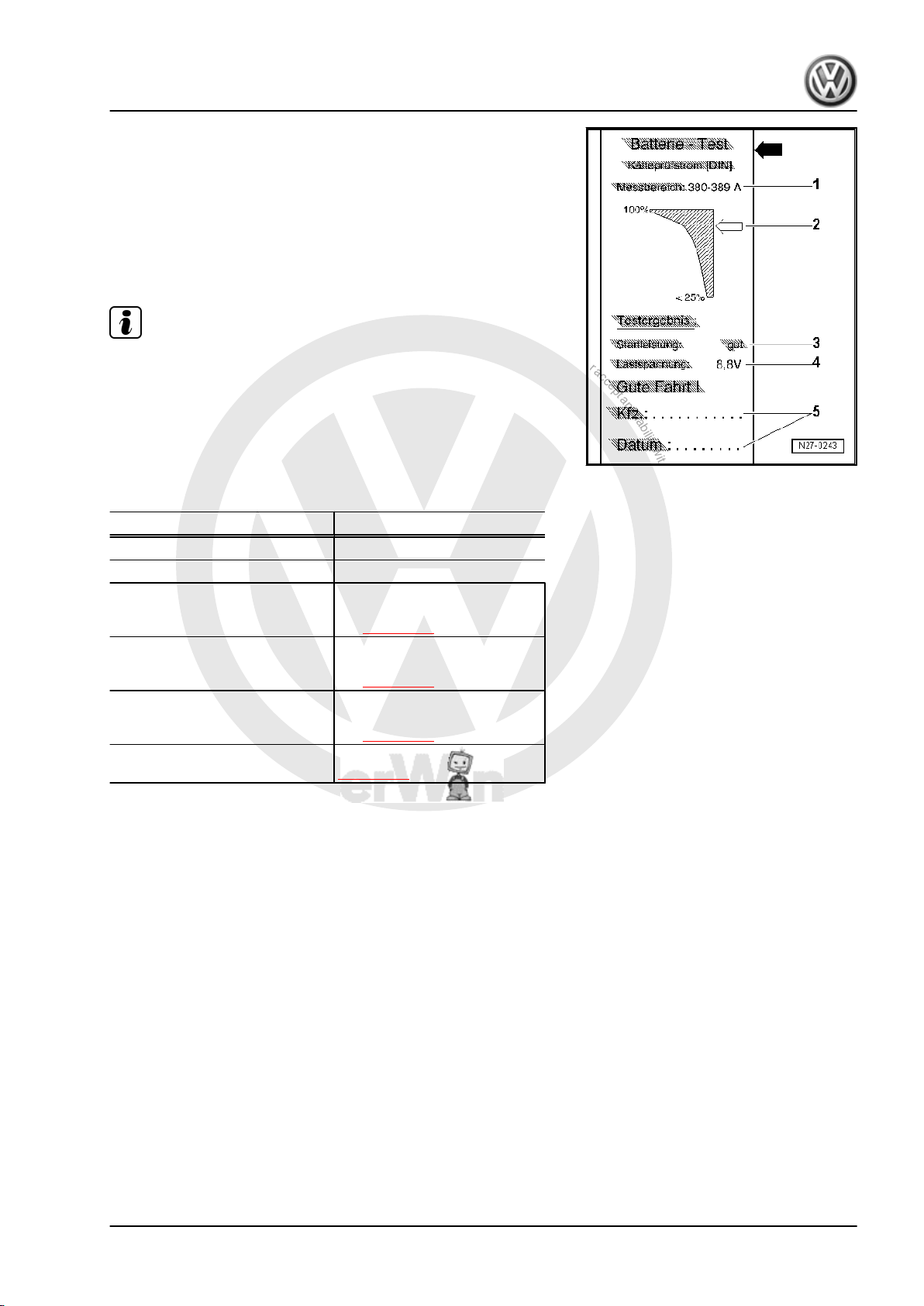
P
r
o
t
e
c
t
e
d
b
y
c
o
p
y
r
i
g
h
t
.
C
o
p
y
i
n
g
f
o
r
p
r
i
v
a
t
e
o
r
c
o
m
m
e
r
c
i
a
l
p
u
r
p
o
s
e
s
,
i
n
p
a
r
t
o
r
i
n
w
h
o
l
e
,
i
s
n
o
t
p
e
r
m
i
t
t
e
d
u
n
l
e
s
s
a
u
t
h
o
r
i
s
e
d
b
y
V
o
l
k
s
w
a
g
e
n
A
G
.
V
o
l
k
s
w
a
g
e
n
A
G
d
o
e
s
n
o
t
g
u
a
r
a
n
t
e
e
o
r
a
c
c
e
p
t
a
n
y
l
i
a
b
i
l
i
t
y
w
i
t
h
r
e
s
p
e
c
t
t
o
t
h
e
c
o
r
r
e
c
t
n
e
s
s
o
f
i
n
f
o
r
m
a
t
i
o
n
i
n
t
h
i
s
d
o
c
u
m
e
n
t
.
C
o
p
y
r
i
g
h
t
b
y
V
o
l
k
s
w
a
g
e
n
A
G
.
2.4.5 Comments concerning test print out
1 — Measuring range selected on tester
2 — Diagram -arrow- indicates battery condition.
3 — Test result
4 — Battery voltage during load test.
5 — Vehicle data and date Must be completed by test personnel
Note
♦
The test printout is required for warranty claims.
♦
Perform test once only. Repeating immediately the test falsi‐
fies the result.
2.4.6 Assessing test results
Printout from battery tester Measure to be performed
Starting capability very good Battery OK.
Starting capability good Battery OK.
Starting capability sufficient Evaluation by carrying out a
current draw test when charg‐
ing ⇒ page 22
Starting capability poor Evaluation by carrying out a
current draw test when charg‐
ing ⇒ page 22
Starting capability very poor Evaluation by carrying out a
current draw test when charg‐
ing ⇒ page 22
Cannot be tested Perform battery charging
⇒ page 25 and repeat test.
Bora 1999 ➤ , Bora Variant 1999 ➤ , CC 2010 ➤ , Eos 2006 ➤ , Golf 199 …
Electrical System, General Information — Edition 07.2010
2. Checking battery 13
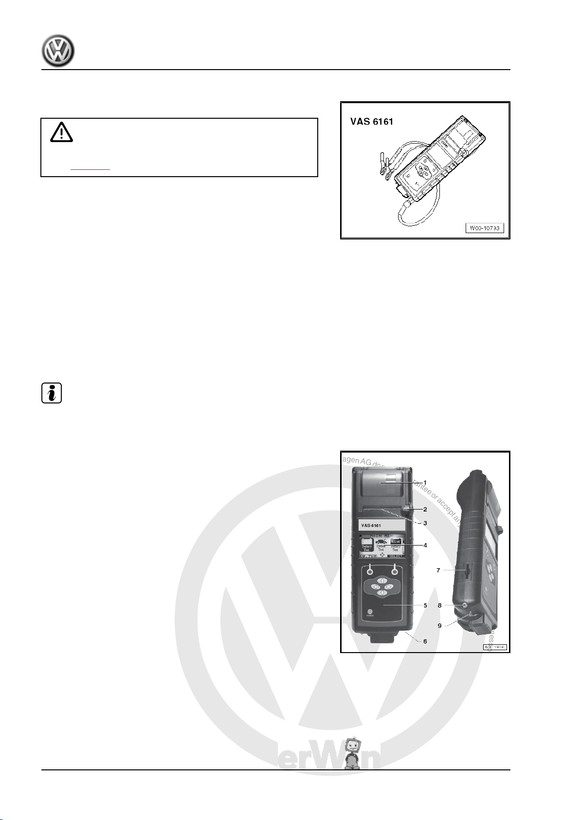
P
r
o
t
e
c
t
e
d
b
y
c
o
p
y
r
i
g
h
t
.
C
o
p
y
i
n
g
f
o
r
p
r
i
v
a
t
e
o
r
c
o
m
m
e
r
c
i
a
l
p
u
r
p
o
s
e
s
,
i
n
p
a
r
t
o
r
i
n
w
h
o
l
e
,
i
s
n
o
t
p
e
r
m
i
t
t
e
d
u
n
l
e
s
s
a
u
t
h
o
r
i
s
e
d
b
y
V
o
l
k
s
w
a
g
e
n
A
G
.
V
o
l
k
s
w
a
g
e
n
A
G
d
o
e
s
n
o
t
g
u
a
r
a
n
t
e
e
o
r
a
c
c
e
p
t
a
n
y
l
i
a
b
i
l
i
t
y
w
i
t
h
r
e
s
p
e
c
t
t
o
t
h
e
c
o
r
r
e
c
t
n
e
s
s
o
f
i
n
f
o
r
m
a
t
i
o
n
i
n
t
h
i
s
d
o
c
u
m
e
n
t
.
C
o
p
y
r
i
g
h
t
b
y
V
o
l
k
s
w
a
g
e
n
A
G
.
2.5 Battery tester with printer -VAS 6161-
General description
WARNING
Danger of injury! Observe warning notices and safety regula‐
tions ⇒ page 2 !
It is not necessary to remove or disconnect battery when using
battery tester with printer -VAS 6161- .
The battery tester with printer -VAS 6161- does not load the bat‐
tery any more. It works on the principle of dynamic conductance
acquisition.
Every battery type is stored in the tester.
Data can be stored on an SD card.
The battery tester with printer -VAS 6161- can be updated via an
interface or an SD card, so that battery data from Volkswagen are
always up to date.
The integrated temperature sensor improves measurement qual‐
ity.
A 2D scanner is available as an option to read data directly from
the bar code of the battery.
Note
Observe the ⇒ operating manual of the battery tester with printer
-VAS 6161- .
2.5.1 Description of battery tester with printer
-VAS 6161-
1 — Integrated printer
2 — Operating lever for paper compartment
3 — Paper slot
4 — LCD screen with main menu
5 — Control panel with On/Off button
6 — Connection for battery test cable
7 — Memory card slot
8 — Infrared temperature sensor
9 — Data transmitter for PC
Bora 1999 ➤ , Bora Variant 1999 ➤ , CC 2010 ➤ , Eos 2006 ➤ , Golf 199 …
Electrical System, General Information — Edition 07.2010
14 Rep. gr.27 — Starter, current supply, CCS
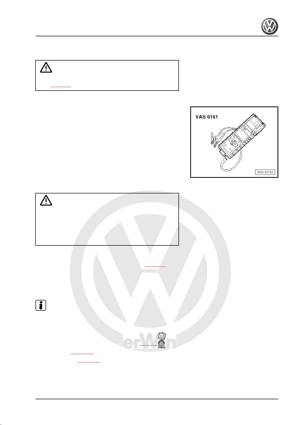
P
r
o
t
e
c
t
e
d
b
y
c
o
p
y
r
i
g
h
t
.
C
o
p
y
i
n
g
f
o
r
p
r
i
v
a
t
e
o
r
c
o
m
m
e
r
c
i
a
l
p
u
r
p
o
s
e
s
,
i
n
p
a
r
t
o
r
i
n
w
h
o
l
e
,
i
s
n
o
t
p
e
r
m
i
t
t
e
d
u
n
l
e
s
s
a
u
t
h
o
r
i
s
e
d
b
y
V
o
l
k
s
w
a
g
e
n
A
G
.
V
o
l
k
s
w
a
g
e
n
A
G
d
o
e
s
n
o
t
g
u
a
r
a
n
t
e
e
o
r
a
c
c
e
p
t
a
n
y
l
i
a
b
i
l
i
t
y
w
i
t
h
r
e
s
p
e
c
t
t
o
t
h
e
c
o
r
r
e
c
t
n
e
s
s
o
f
i
n
f
o
r
m
a
t
i
o
n
i
n
t
h
i
s
d
o
c
u
m
e
n
t
.
C
o
p
y
r
i
g
h
t
b
y
V
o
l
k
s
w
a
g
e
n
A
G
.
2.5.2 Perform battery test with battery tester
with printer -VAS 6161- .
WARNING
Danger of injury! Observe warning notices and safety regula‐
tions ⇒ page 2 !
Special tools and workshop equipment required
♦ Battery tester with printer -VAS 6161-
Performing battery test:
WARNING
Batteries where the magic eye is colourless or light yellow must
not be checked or charged. Do not slave/jump start the vehicle!
Danger of explosion when checking and charging or slave/
jump starting
These batteries must be renewed.
– Switch off ignition and all electrical consumers.
– Check magic eye on batteries with magic eye ⇒ page 5 .
– Switch on unit.
– Connect red terminal „+“ of tester to positive terminal.
– Connect black terminal „-“ of tester to negative terminal.
Note
Ensure test clamps have a good contact!
– Select one of the following functions.
♦ Maintenance test (only in new cars before registration, in sta‐
tionary and stock maintenance programme ⇒ page 16 )
♦ Service test ⇒ page 16
♦ Guarantee test ⇒ page 17
Bora 1999 ➤ , Bora Variant 1999 ➤ , CC 2010 ➤ , Eos 2006 ➤ , Golf 199 …
Electrical System, General Information — Edition 07.2010
2. Checking battery 15
P
r
o
t
e
c
t
e
d
b
y
c
o
p
y
r
i
g
h
t
.
C
o
p
y
i
n
g
f
o
r
p
r
i
v
a
t
e
o
r
c
o
m
m
e
r
c
i
a
l
p
u
r
p
o
s
e
s
,
i
n
p
a
r
t
o
r
i
n
w
h
o
l
e
,
i
s
n
o
t
p
e
r
m
i
t
t
e
d
u
n
l
e
s
s
a
u
t
h
o
r
i
s
e
d
b
y
V
o
l
k
s
w
a
g
e
n
A
G
.
V
o
l
k
s
w
a
g
e
n
A
G
d
o
e
s
n
o
t
g
u
a
r
a
n
t
e
e
o
r
a
c
c
e
p
t
a
n
y
l
i
a
b
i
l
i
t
y
w
i
t
h
r
e
s
p
e
c
t
t
o
t
h
e
c
o
r
r
e
c
t
n
e
s
s
o
f
i
n
f
o
r
m
a
t
i
o
n
i
n
t
h
i
s
d
o
c
u
m
e
n
t
.
C
o
p
y
r
i
g
h
t
b
y
V
o
l
k
s
w
a
g
e
n
A
G
.
Note
♦
The test is completed after about 10 seconds.
♦
The result of the test is printed out by the printer.
♦
The tester requires no cooling phase before it is ready for the
next measurement.
2.5.3 Performing maintenance test
WARNING
Batteries where the magic eye is colourless or light yellow must
not be checked or charged. Do not slave/jump start the vehicle!
Danger of explosion when checking and charging or slave/
jump starting
These batteries must be renewed.
– Select „Maintenance test“ in the menu.
– Connect scanner.
Note
If no scanner is available, write vehicle identification number on
test printout by hand.
– Scan in vehicle identification number.
– Select „On battery terminal“ or „On jump-start point“.
– Scan in barcode or select type and manufacturer manually in
menu.
– Measure temperature. Hold temperature sensor about 5 cm
above terminal connection until temperature stabilises.
– Start test.
– Print out test log if necessary.
2.5.4 Perform service test
WARNING
Batteries where the magic eye is colourless or light yellow must
not be checked or charged. Do not slave/jump start the vehicle!
Danger of explosion when checking and charging or slave/
jump starting
These batteries must be renewed.
– Select „Service test“ in the menu.
– Select „On battery terminal“ or „On jump-start point“.
– Select vehicle type.
– Measure temperature. Hold temperature sensor about 5 cm
above one battery terminal until temperature stabilises.
Bora 1999 ➤ , Bora Variant 1999 ➤ , CC 2010 ➤ , Eos 2006 ➤ , Golf 199 …
Electrical System, General Information — Edition 07.2010
16 Rep. gr.27 — Starter, current supply, CCS
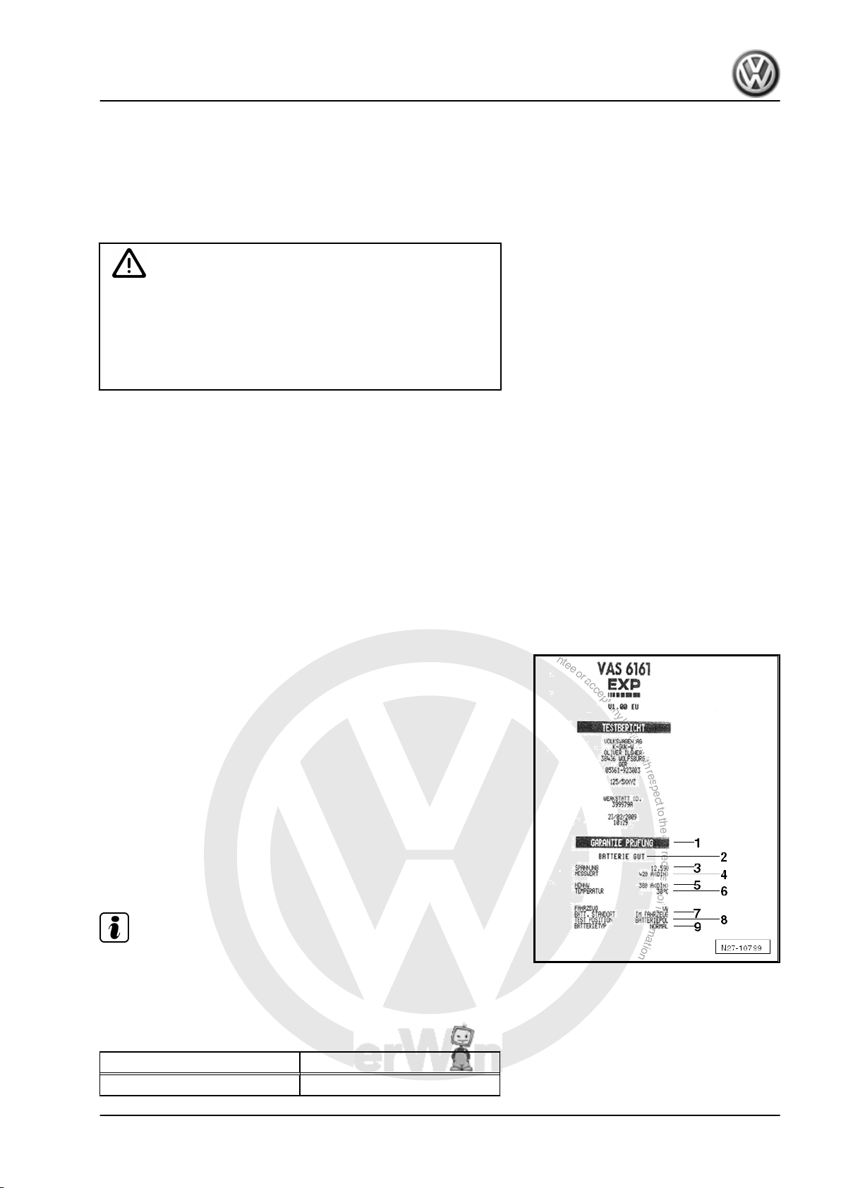
P
r
o
t
e
c
t
e
d
b
y
c
o
p
y
r
i
g
h
t
.
C
o
p
y
i
n
g
f
o
r
p
r
i
v
a
t
e
o
r
c
o
m
m
e
r
c
i
a
l
p
u
r
p
o
s
e
s
,
i
n
p
a
r
t
o
r
i
n
w
h
o
l
e
,
i
s
n
o
t
p
e
r
m
i
t
t
e
d
u
n
l
e
s
s
a
u
t
h
o
r
i
s
e
d
b
y
V
o
l
k
s
w
a
g
e
n
A
G
.
V
o
l
k
s
w
a
g
e
n
A
G
d
o
e
s
n
o
t
g
u
a
r
a
n
t
e
e
o
r
a
c
c
e
p
t
a
n
y
l
i
a
b
i
l
i
t
y
w
i
t
h
r
e
s
p
e
c
t
t
o
t
h
e
c
o
r
r
e
c
t
n
e
s
s
o
f
i
n
f
o
r
m
a
t
i
o
n
i
n
t
h
i
s
d
o
c
u
m
e
n
t
.
C
o
p
y
r
i
g
h
t
b
y
V
o
l
k
s
w
a
g
e
n
A
G
.
– Select battery type „Normal“, „AGM“, „2*6V“ or „Gel“.
– Select „CCA“, „JIS“, „DIN“, „SAE“, „IEC“ or „EN“ norm.
– Start test.
– Print out test log if necessary.
2.5.5 Perform guarantee test
WARNING
Batteries where the magic eye is colourless or light yellow must
not be checked or charged. Do not slave/jump start the vehicle!
Danger of explosion when checking and charging or slave/
jump starting
These batteries must be renewed.
– Select „Guarantee test“ in the menu.
– Select „In vehicle“ or „Outside vehicle“.
– Select „On battery terminal“ or „On jump-start point“.
– Select vehicle type.
– Measure temperature. Hold temperature sensor about 5 cm
above one battery terminal until temperature stabilises.
– Select battery type „Normal“, „AGM“, „2*6V“ or „Gel“ or scan
in.
– Select battery capacity or scan in.
– Start test.
– Print out test log if necessary.
2.5.6 Comments concerning test print out
1 — Check type.
2 — Battery test result
3 — Measured voltage
4 — Measured cold start value of battery.
5 — Nominal cold start value of battery selected on tester.
6 — Measured temperature of battery.
7 — Fitting location of battery
8 — Position of battery clamp selected on tester
9 — Selected battery technology.
Note
The test printout is required for warranty claims.
2.5.7 Assessing test results
Evaluating battery test results for guarantee and service tests
Battery test results Measures
Battery OK No measures on battery
Bora 1999 ➤ , Bora Variant 1999 ➤ , CC 2010 ➤ , Eos 2006 ➤ , Golf 199 …
Electrical System, General Information — Edition 07.2010
2. Checking battery 17
P
r
o
t
e
c
t
e
d
b
y
c
o
p
y
r
i
g
h
t
.
C
o
p
y
i
n
g
f
o
r
p
r
i
v
a
t
e
o
r
c
o
m
m
e
r
c
i
a
l
p
u
r
p
o
s
e
s
,
i
n
p
a
r
t
o
r
i
n
w
h
o
l
e
,
i
s
n
o
t
p
e
r
m
i
t
t
e
d
u
n
l
e
s
s
a
u
t
h
o
r
i
s
e
d
b
y
V
o
l
k
s
w
a
g
e
n
A
G
.
V
o
l
k
s
w
a
g
e
n
A
G
d
o
e
s
n
o
t
g
u
a
r
a
n
t
e
e
o
r
a
c
c
e
p
t
a
n
y
l
i
a
b
i
l
i
t
y
w
i
t
h
r
e
s
p
e
c
t
t
o
t
h
e
c
o
r
r
e
c
t
n
e
s
s
o
f
i
n
f
o
r
m
a
t
i
o
n
i
n
t
h
i
s
d
o
c
u
m
e
n
t
.
C
o
p
y
r
i
g
h
t
b
y
V
o
l
k
s
w
a
g
e
n
A
G
.
Battery test results Measures
Battery OK — recharge. Charge battery ⇒ page 25 . In
case of discharging, look for
fault
Perform current draw test Perform current draw test
⇒ page 22 . Fully charge bat‐
tery ⇒ page 25 and repeat
test.
Renew battery. Disconnect battery and repeat
test. The result „Renew battery“
may be caused by a weak cable
contact.
Battery cell defective — renew. Renew battery.
Check connection. Connect cable directly to bat‐
tery and not to jump start termi‐
nal.
Evaluating battery test results for maintenance test
Battery test results Measures
Battery OK No measure
Charge battery immediately. Charge battery fully
⇒ page 25 .
Mark as defective. Mark as defective.
Check tester connection. Disconnect battery and repeat
test. The result „Check tester
connection“ may be caused by
a weak cable contact.
Check connection. Connect cable directly to bat‐
tery and not to jump start termi‐
nal.
Noises Wait until measured value ap‐
pears on display.
2.6 Midtronics -MCR340V- battery tester
only for USA/Canada vehicles
General description ⇒ page 18
Perform battery test with Midtronics -MCR340V- battery tester
⇒ page 19 .
Dealing with problems with Midtronics -MCR340V- battery tester
⇒ page 21
2.6.1 General description
WARNING
Danger of injury.
Before working on the battery, read through the warning and
safety regulations carefully, and comply with them ⇒ page 2 .
Dispose of electrolyte (mixture of sulphuric acid and water)
safely! Waste electrolyte is only allowed to be disposed of at
appropriately indicated collecting points. Comply with the lo‐
cally applicable disposal guidelines.
Do not test batteries that are liberating gas. Otherwise, there
is a danger of explosion.
Bora 1999 ➤ , Bora Variant 1999 ➤ , CC 2010 ➤ , Eos 2006 ➤ , Golf 199 …
Electrical System, General Information — Edition 07.2010
18 Rep. gr.27 — Starter, current supply, CCS
P
r
o
t
e
c
t
e
d
b
y
c
o
p
y
r
i
g
h
t
.
C
o
p
y
i
n
g
f
o
r
p
r
i
v
a
t
e
o
r
c
o
m
m
e
r
c
i
a
l
p
u
r
p
o
s
e
s
,
i
n
p
a
r
t
o
r
i
n
w
h
o
l
e
,
i
s
n
o
t
p
e
r
m
i
t
t
e
d
u
n
l
e
s
s
a
u
t
h
o
r
i
s
e
d
b
y
V
o
l
k
s
w
a
g
e
n
A
G
.
V
o
l
k
s
w
a
g
e
n
A
G
d
o
e
s
n
o
t
g
u
a
r
a
n
t
e
e
o
r
a
c
c
e
p
t
a
n
y
l
i
a
b
i
l
i
t
y
w
i
t
h
r
e
s
p
e
c
t
t
o
t
h
e
c
o
r
r
e
c
t
n
e
s
s
o
f
i
n
f
o
r
m
a
t
i
o
n
i
n
t
h
i
s
d
o
c
u
m
e
n
t
.
C
o
p
y
r
i
g
h
t
b
y
V
o
l
k
s
w
a
g
e
n
A
G
.
WARNING
Batteries where the magic eye is colourless or light yellow must
not be checked or charged. Do not slave/jump start the vehicle!
Danger of explosion when checking and charging or slave/
jump starting
These batteries must be renewed.
Note
To prevent damage to the battery and vehicle, note the types of
battery and the remarks given ⇒ page 1 .
Batteries in VW vehicles are only allowed to be tested with battery
testers approved by VW. In the USA/Canada, it is permitted for
the Midtronics -MCR340V- battery tester to be used.
Read all the information about safety, setup and operation in the
operating instructions for the Midtronics -MCR340V- battery test‐
er and follow the instructions to the letter.
Refer to ⇒ Self-study programme No. ; Vehicle batteries for more
information.
The following charging and analysis procedures apply to all bat‐
teries, all battery installation locations (engine compartment or
luggage compartment) and battery purposes (starter battery or
second/convenience battery).
Always comply with the safety regulations, the regulations for
setting up the battery tester, the display menu/display buttons,
LEDs and the operating procedures described in the ⇒ operating
manual MCR340V .
Note
Observe and comply with all subsections, remarks and referen‐
ces to the vehicle and battery type, etc. to be tested.
2.6.2 Performing battery test with Midtronics —
MCR340V- battery tester
Prerequisites:
WARNING
Before working on the battery, read through the warning and
safety regulations carefully, and comply with them ⇒ page 2 .
Batteries where the magic eye is colourless or light yellow must
not be checked or charged. Do not slave/jump start the vehicle!
Danger of explosion when checking and charging or slave/
jump starting
These batteries must be renewed.
– Read general description ⇒ page 18 .
– Perform visual check ⇒ page 6 .
Bora 1999 ➤ , Bora Variant 1999 ➤ , CC 2010 ➤ , Eos 2006 ➤ , Golf 199 …
Electrical System, General Information — Edition 07.2010
2. Checking battery 19
P
r
o
t
e
c
t
e
d
b
y
c
o
p
y
r
i
g
h
t
.
C
o
p
y
i
n
g
f
o
r
p
r
i
v
a
t
e
o
r
c
o
m
m
e
r
c
i
a
l
p
u
r
p
o
s
e
s
,
i
n
p
a
r
t
o
r
i
n
w
h
o
l
e
,
i
s
n
o
t
p
e
r
m
i
t
t
e
d
u
n
l
e
s
s
a
u
t
h
o
r
i
s
e
d
b
y
V
o
l
k
s
w
a
g
e
n
A
G
.
V
o
l
k
s
w
a
g
e
n
A
G
d
o
e
s
n
o
t
g
u
a
r
a
n
t
e
e
o
r
a
c
c
e
p
t
a
n
y
l
i
a
b
i
l
i
t
y
w
i
t
h
r
e
s
p
e
c
t
t
o
t
h
e
c
o
r
r
e
c
t
n
e
s
s
o
f
i
n
f
o
r
m
a
t
i
o
n
i
n
t
h
i
s
d
o
c
u
m
e
n
t
.
C
o
p
y
r
i
g
h
t
b
y
V
o
l
k
s
w
a
g
e
n
A
G
.
– Open bonnet or cover for other installation location of battery.
– Determine whether battery type is „Standard“ or „AGM“.
– Remove covers from battery positive and negative terminals.
– Use wing covers or other kinds of cover before you use equip‐
ment in engine compartment or interior.
– Close all doors.
Note
♦
Battery temperature must be at least 10 °C.
♦
For additional information, refer to the ⇒ operating manual
INC 940 .
Perform test:
WARNING
Batteries where the magic eye is colourless or light yellow must
not be checked or charged. Do not slave/jump start the vehicle!
Danger of explosion when checking and charging or slave/
jump starting
These batteries must be renewed.
– Switch off ignition and all electrical consumers.
– Check magic eye on batteries with magic eye ⇒ page 5 .
– Switch on tester.
– Connect red terminal „+“ of tester to positive terminal.
– Connect black terminal „-“ of tester to negative terminal.
Note
Ensure test clamps have a good contact!
– Select „In vehicle“ or „Outside vehicle“.
– Select „Warranty test“.
Note
Use the print function of the Midtronics -MCR340- tester if the test
results are required for handling warranty applications.
– Select battery type „Standard “ or „AGM“.
– Make a note of the DIN value of the battery as shown on the
battery sticker. If there is no DIN value on the sticker, make a
note of the SAE value.
– Enter DIN value in tester and perform battery test ⇒ operating
manual MCR340V .
– If you are using SAE value, access „Miscellaneous“ menu and
change from „DIN“ to „SAE“ ⇒ operating manual MCR340V .
Bora 1999 ➤ , Bora Variant 1999 ➤ , CC 2010 ➤ , Eos 2006 ➤ , Golf 199 …
Electrical System, General Information — Edition 07.2010
20 Rep. gr.27 — Starter, current supply, CCS
P
r
o
t
e
c
t
e
d
b
y
c
o
p
y
r
i
g
h
t
.
C
o
p
y
i
n
g
f
o
r
p
r
i
v
a
t
e
o
r
c
o
m
m
e
r
c
i
a
l
p
u
r
p
o
s
e
s
,
i
n
p
a
r
t
o
r
i
n
w
h
o
l
e
,
i
s
n
o
t
p
e
r
m
i
t
t
e
d
u
n
l
e
s
s
a
u
t
h
o
r
i
s
e
d
b
y
V
o
l
k
s
w
a
g
e
n
A
G
.
V
o
l
k
s
w
a
g
e
n
A
G
d
o
e
s
n
o
t
g
u
a
r
a
n
t
e
e
o
r
a
c
c
e
p
t
a
n
y
l
i
a
b
i
l
i
t
y
w
i
t
h
r
e
s
p
e
c
t
t
o
t
h
e
c
o
r
r
e
c
t
n
e
s
s
o
f
i
n
f
o
r
m
a
t
i
o
n
i
n
t
h
i
s
d
o
c
u
m
e
n
t
.
C
o
p
y
r
i
g
h
t
b
y
V
o
l
k
s
w
a
g
e
n
A
G
.
Note
Always use DIN value from battery sticker! Otherwise, test result
will be falsified.
2.6.3 Assessing test results
Results of battery test:
Battery test results Measures
Battery OK None
Good — charge Charge battery ⇒ page 55 .
Use Incharge Charge battery ⇒ page 55 .
Renew battery. Renew battery ⇒ Electrical sys‐
tem; Rep. gr. 27 ; Removing
and installing battery
Battery cell defective Renew battery ⇒ Electrical sys‐
tem; Rep. gr. 27 ; Removing
and installing battery
2.6.4 Dealing with problems with Midtronics —
MCR340V- battery tester
Under certain circumstances, the display may show errors or
messages according to status.
The most frequent display messages are listed below, together
with suggested solutions.
Note
For messages not listed here, please refer to ⇒ operating manual
MCR340V .
Display message Measures
No display – Check whether terminals of
battery tester are firmly con‐
nected to battery terminals.
– Check battery terminals are
tightened according to reg‐
ulations and do not have
corrosion.
– Charge battery
⇒ page 55 .
System noise – Switch off all electrical con‐
sumers.
– Wait until all electrical loads
monitored by onboard sup‐
ply control unit have switch‐
ed off.
– Remove ignition key.
– Disconnect any suspect
electrical equipment not
connected to onboard sup‐
ply as standard.
Bora 1999 ➤ , Bora Variant 1999 ➤ , CC 2010 ➤ , Eos 2006 ➤ , Golf 199 …
Electrical System, General Information — Edition 07.2010
2. Checking battery 21
P
r
o
t
e
c
t
e
d
b
y
c
o
p
y
r
i
g
h
t
.
C
o
p
y
i
n
g
f
o
r
p
r
i
v
a
t
e
o
r
c
o
m
m
e
r
c
i
a
l
p
u
r
p
o
s
e
s
,
i
n
p
a
r
t
o
r
i
n
w
h
o
l
e
,
i
s
n
o
t
p
e
r
m
i
t
t
e
d
u
n
l
e
s
s
a
u
t
h
o
r
i
s
e
d
b
y
V
o
l
k
s
w
a
g
e
n
A
G
.
V
o
l
k
s
w
a
g
e
n
A
G
d
o
e
s
n
o
t
g
u
a
r
a
n
t
e
e
o
r
a
c
c
e
p
t
a
n
y
l
i
a
b
i
l
i
t
y
w
i
t
h
r
e
s
p
e
c
t
t
o
t
h
e
c
o
r
r
e
c
t
n
e
s
s
o
f
i
n
f
o
r
m
a
t
i
o
n
i
n
t
h
i
s
d
o
c
u
m
e
n
t
.
C
o
p
y
r
i
g
h
t
b
y
V
o
l
k
s
w
a
g
e
n
A
G
.
Wait a few minutes and test again ⇒ page 19 .
Note
If you have performed test at jump-start point and message does
not disappear, perform test directly on battery.
2.7 Current draw test
WARNING
Batteries where the magic eye is colourless or light yellow must
not be checked or charged. Do not slave/jump start the vehicle!
Danger of explosion when checking and charging or slave/
jump starting
These batteries must be renewed.
Note
♦
Ensure that the correct charging mode is set on the charger
so that the current draw test is not falsified.
♦
VAS 5095 A ⇒ page 26
♦
VAS 5900 ⇒ page 30
♦
VAS 5903 ⇒ page 41
To quickly ascertain the state of discharged batteries, the battery
current draw test whilst charging helps to determine whether the
battery must be replaced or fully recharged.
Note
For battery tester with printer -VAS 6161- , the current draw test
must always be performed when the test result „Perform current
draw test“ appears on the display.
The current draw test must be carried out when the test result with
battery tester with printer -VAS 5097A- is as follows:
1 — Starting output sufficient
2 — Starting output poor
3 — Starting output very poor
4 — Cannot be tested – charge battery and repeat test.
— and when the tester will not switch on (no LED, no printout)
Depending on the test result ⇒ page 13 with battery tester with
printer -VAS 5097A- , further procedures or tests may be required
before making a final decision on the condition of the battery.
Performing a current draw test whilst charging a battery will quick‐
ly establish whether a partly or fully discharged battery
⇒ page 59 can be recharged to return it to a serviceable condi‐
tion.
Bora 1999 ➤ , Bora Variant 1999 ➤ , CC 2010 ➤ , Eos 2006 ➤ , Golf 199 …
Electrical System, General Information — Edition 07.2010
22 Rep. gr.27 — Starter, current supply, CCS
P
r
o
t
e
c
t
e
d
b
y
c
o
p
y
r
i
g
h
t
.
C
o
p
y
i
n
g
f
o
r
p
r
i
v
a
t
e
o
r
c
o
m
m
e
r
c
i
a
l
p
u
r
p
o
s
e
s
,
i
n
p
a
r
t
o
r
i
n
w
h
o
l
e
,
i
s
n
o
t
p
e
r
m
i
t
t
e
d
u
n
l
e
s
s
a
u
t
h
o
r
i
s
e
d
b
y
V
o
l
k
s
w
a
g
e
n
A
G
.
V
o
l
k
s
w
a
g
e
n
A
G
d
o
e
s
n
o
t
g
u
a
r
a
n
t
e
e
o
r
a
c
c
e
p
t
a
n
y
l
i
a
b
i
l
i
t
y
w
i
t
h
r
e
s
p
e
c
t
t
o
t
h
e
c
o
r
r
e
c
t
n
e
s
s
o
f
i
n
f
o
r
m
a
t
i
o
n
i
n
t
h
i
s
d
o
c
u
m
e
n
t
.
C
o
p
y
r
i
g
h
t
b
y
V
o
l
k
s
w
a
g
e
n
A
G
.
Test requirements
♦ When charging a battery, battery temperature must be at least
≥ +10 °C.
♦ The charger must be capable of outputting a charge current of
at least 30 A, as for example with VAS 5095A, VAS 5900, VAS
5903
♦ The battery’s current draw must be measured with a current
pick-up clamp, e.g. VAS 5051B/7, when charging with battery
charger -VAS 5095A- . Battery charger -VAS 5900- and bat‐
tery charger -VAS 5903- display the current draw on the unit.
– Connect battery to battery charger and start charging se‐
quence.
– Measure charging current of battery after 5 minutes.
Test result:
If the current draw A is higher than 10 % of the nominal capacity
(e.g. > 6.1 A for a 61 Ah battery), fully charge battery and test
again.
Note
For Eos with two 6V absorbent glass mat batteries, the charge
current must only be 5 % higher than the nominal capacity of the
battery. Example for Eos: the 50 Ah battery must have a charge
current higher than 2.5 A after 5 minutes of starting the charging
sequence.
– Fully charge the battery when the charge current is higher than
10 % of the nominal capacity (observe exception for Eos in
above note).
– Perform battery test after allowing battery to rest for two hours
⇒ page 9 .
If the charge current, in amperes, lies below 10 % of the nominal
capacity after 5 minutes of starting the charging sequence (5 %
for the 2 x 6 volt batteries in Eos) (example for 50 Ah battery <
5A), renew battery. For Guarantee and ex-gratia cases: complete
battery test sheet and keep it with the battery.
2.8 Checking no-load voltage of battery on
stock and stored vehicles
WARNING
Danger of injury! Observe warning notices and safety regula‐
tions ⇒ page 2 !
Note
♦
The no-load voltage test may only be carried out to assess the
condition of the battery on stock and stored vehicles within the
framework of prescribed maintenance.
♦
The no-load test serves to determine whether a battery on a
stock or stored vehicle requires recharging ⇒ Maintenance
tables „Service for stock and stored vehicles“ .
Special tools and workshop equipment required
Bora 1999 ➤ , Bora Variant 1999 ➤ , CC 2010 ➤ , Eos 2006 ➤ , Golf 199 …
Electrical System, General Information — Edition 07.2010
2. Checking battery 23
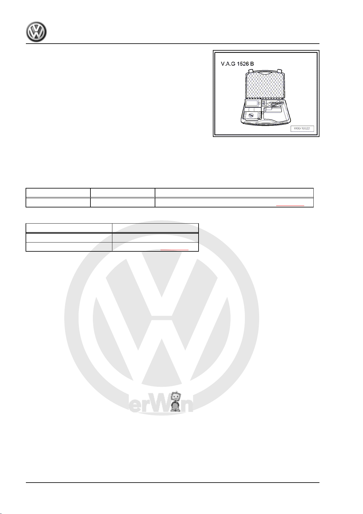
P
r
o
t
e
c
t
e
d
b
y
c
o
p
y
r
i
g
h
t
.
C
o
p
y
i
n
g
f
o
r
p
r
i
v
a
t
e
o
r
c
o
m
m
e
r
c
i
a
l
p
u
r
p
o
s
e
s
,
i
n
p
a
r
t
o
r
i
n
w
h
o
l
e
,
i
s
n
o
t
p
e
r
m
i
t
t
e
d
u
n
l
e
s
s
a
u
t
h
o
r
i
s
e
d
b
y
V
o
l
k
s
w
a
g
e
n
A
G
.
V
o
l
k
s
w
a
g
e
n
A
G
d
o
e
s
n
o
t
g
u
a
r
a
n
t
e
e
o
r
a
c
c
e
p
t
a
n
y
l
i
a
b
i
l
i
t
y
w
i
t
h
r
e
s
p
e
c
t
t
o
t
h
e
c
o
r
r
e
c
t
n
e
s
s
o
f
i
n
f
o
r
m
a
t
i
o
n
i
n
t
h
i
s
d
o
c
u
m
e
n
t
.
C
o
p
y
r
i
g
h
t
b
y
V
o
l
k
s
w
a
g
e
n
A
G
.
♦ Hand multimeter -V.A.G 1526 B-
Test conditions
The battery must not have been charged or discharged within the
last 2 days.
– Check battery no-load voltage with hand multimeter -V.A.G
1526 B- .
No-load voltage Charge Condition of battery
11.60 V 0 % Discharged, no capacity Heavily discharged ⇒ page 59 .
Measured value Measure to be performed
No-load voltage ≥ 12.5 V No-load voltage OK
No-load voltage < 12.5 V Charging battery ⇒ page 25
Bora 1999 ➤ , Bora Variant 1999 ➤ , CC 2010 ➤ , Eos 2006 ➤ , Golf 199 …
Electrical System, General Information — Edition 07.2010
24 Rep. gr.27 — Starter, current supply, CCS
P
r
o
t
e
c
t
e
d
b
y
c
o
p
y
r
i
g
h
t
.
C
o
p
y
i
n
g
f
o
r
p
r
i
v
a
t
e
o
r
c
o
m
m
e
r
c
i
a
l
p
u
r
p
o
s
e
s
,
i
n
p
a
r
t
o
r
i
n
w
h
o
l
e
,
i
s
n
o
t
p
e
r
m
i
t
t
e
d
u
n
l
e
s
s
a
u
t
h
o
r
i
s
e
d
b
y
V
o
l
k
s
w
a
g
e
n
A
G
.
V
o
l
k
s
w
a
g
e
n
A
G
d
o
e
s
n
o
t
g
u
a
r
a
n
t
e
e
o
r
a
c
c
e
p
t
a
n
y
l
i
a
b
i
l
i
t
y
w
i
t
h
r
e
s
p
e
c
t
t
o
t
h
e
c
o
r
r
e
c
t
n
e
s
s
o
f
i
n
f
o
r
m
a
t
i
o
n
i
n
t
h
i
s
d
o
c
u
m
e
n
t
.
C
o
p
y
r
i
g
h
t
b
y
V
o
l
k
s
w
a
g
e
n
A
G
.
3 Charging battery
WARNING
Danger of injury! Observe warning notices and safety regula‐
tions ⇒ page 2 !
Caution
To prevent damage to the battery and vehicle, the following
should be observed concerning types of battery ⇒ page 1 .
WARNING
Batteries where the magic eye is colourless or light yellow must
not be checked or charged. Do not slave/jump start the vehicle!
Danger of explosion when checking and charging or slave/
jump starting
These batteries must be renewed.
3.1 Battery charger -VAS 5095 A-
This chapter describes the basic functions of the battery charger
-VAS 5095 A- . For additional information refer to ⇒ operating
instructions for battery charger -VAS 5095 A- .
Note
♦
The effective charging current can not be read on these units.
The charge current must be read externally using a pick-up
clamp.
♦
Observe ⇒ operating instructions for battery charger -VAS
5095 A- .
3.1.1 Description of battery charger -VAS
5095 A-
The battery charger -VAS 5095- is suitable for charging all 12V
batteries supplied by Volkswagen.
Bora 1999 ➤ , Bora Variant 1999 ➤ , CC 2010 ➤ , Eos 2006 ➤ , Golf 199 …
Electrical System, General Information — Edition 07.2010
3. Charging battery 25
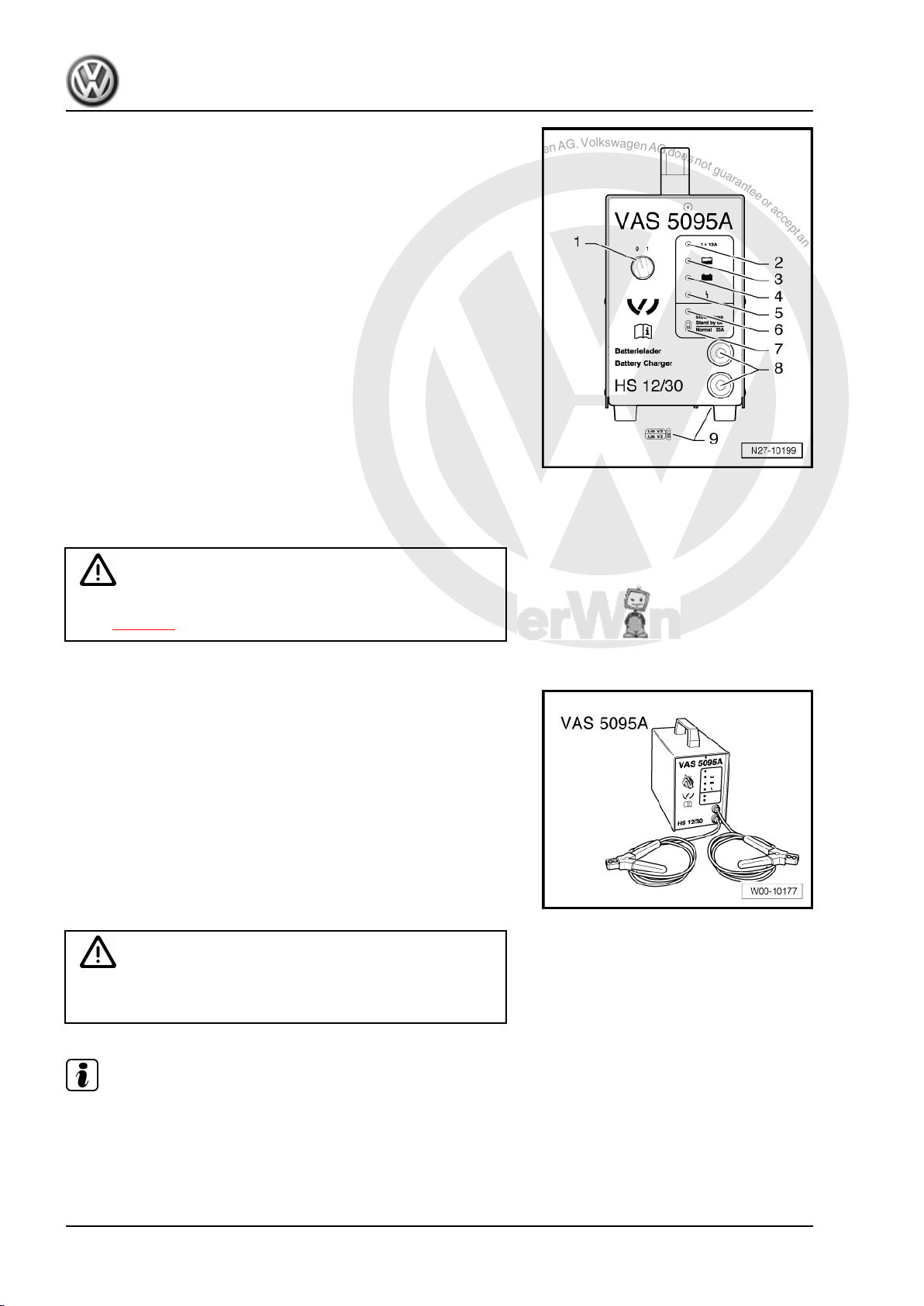
P
r
o
t
e
c
t
e
d
b
y
c
o
p
y
r
i
g
h
t
.
C
o
p
y
i
n
g
f
o
r
p
r
i
v
a
t
e
o
r
c
o
m
m
e
r
c
i
a
l
p
u
r
p
o
s
e
s
,
i
n
p
a
r
t
o
r
i
n
w
h
o
l
e
,
i
s
n
o
t
p
e
r
m
i
t
t
e
d
u
n
l
e
s
s
a
u
t
h
o
r
i
s
e
d
b
y
V
o
l
k
s
w
a
g
e
n
A
G
.
V
o
l
k
s
w
a
g
e
n
A
G
d
o
e
s
n
o
t
g
u
a
r
a
n
t
e
e
o
r
a
c
c
e
p
t
a
n
y
l
i
a
b
i
l
i
t
y
w
i
t
h
r
e
s
p
e
c
t
t
o
t
h
e
c
o
r
r
e
c
t
n
e
s
s
o
f
i
n
f
o
r
m
a
t
i
o
n
i
n
t
h
i
s
d
o
c
u
m
e
n
t
.
C
o
p
y
r
i
g
h
t
b
y
V
o
l
k
s
w
a
g
e
n
A
G
.
The battery charger charges without peaks in amperage or volt‐
age. This will not adversely effect the onboard electronics. The
battery can remain in the vehicle while it is being charged and
need not be disconnected.
Battery charger -VAS 5095 A-
1 — ON / OFF switch (0 = charger OFF)
2 — Charging current indicator (I > 12 A)
3 — Charging current indicator, battery partially charged > 90 %
4 — Maintaining charge; lights up green when battery is fully charg‐
ed
5 — Malfunction indicator
6 — Support mode indicator
7 — Support mode/normal mode changer-over switch
8 — Charger cable, red terminal „+“, black terminal „-“
9 — Battery type change-over switch (on base of charger unit)
3.1.2 Charging battery with battery charger —
VAS 5095 A-
WARNING
Danger of injury! Observe warning notices and safety regula‐
tions ⇒ page 2 !
Special tools and workshop equipment required
♦ Battery charger -VAS 5095 A-
Caution
Always set battery type 2.4 V/C (volts/battery cell) when charg‐
ing! This applies for all batteries.
Note
The battery must have a temperature of at least 10 °C.
Bora 1999 ➤ , Bora Variant 1999 ➤ , CC 2010 ➤ , Eos 2006 ➤ , Golf 199 …
Electrical System, General Information — Edition 07.2010
26 Rep. gr.27 — Starter, current supply, CCS
P
r
o
t
e
c
t
e
d
b
y
c
o
p
y
r
i
g
h
t
.
C
o
p
y
i
n
g
f
o
r
p
r
i
v
a
t
e
o
r
c
o
m
m
e
r
c
i
a
l
p
u
r
p
o
s
e
s
,
i
n
p
a
r
t
o
r
i
n
w
h
o
l
e
,
i
s
n
o
t
p
e
r
m
i
t
t
e
d
u
n
l
e
s
s
a
u
t
h
o
r
i
s
e
d
b
y
V
o
l
k
s
w
a
g
e
n
A
G
.
V
o
l
k
s
w
a
g
e
n
A
G
d
o
e
s
n
o
t
g
u
a
r
a
n
t
e
e
o
r
a
c
c
e
p
t
a
n
y
l
i
a
b
i
l
i
t
y
w
i
t
h
r
e
s
p
e
c
t
t
o
t
h
e
c
o
r
r
e
c
t
n
e
s
s
o
f
i
n
f
o
r
m
a
t
i
o
n
i
n
t
h
i
s
d
o
c
u
m
e
n
t
.
C
o
p
y
r
i
g
h
t
b
y
V
o
l
k
s
w
a
g
e
n
A
G
.
WARNING
Batteries where the magic eye is colourless or light yellow must
not be checked or charged. Do not slave/jump start the vehicle!
Danger of explosion when checking and charging or slave/
jump starting
These batteries must be renewed.
– Switch off ignition and all electrical consumers.
– Check setting for battery type on type of battery switch
⇒ page 25 . Must be set to 2.4 V/C (volts/battery cell).
– Connect red terminal clamp „+“ of charger unit to positive ter‐
minal on battery.
Note
In vehicles with start/stop function and battery monitor control unit
-J367- fitted, black terminal clamp „-“ must be connected to body
earth. Connecting it to battery negative terminal will cause start/
stop system to malfunction.
– Connect black terminal clamp „-“ of battery charger to negative
terminal.
– Switch on battery charger ⇒ page 25 .
The charging current indicators ⇒ page 26 -2- and -3- light up
yellow. When only the light emitting diode (LED) -3- lights up yel‐
low, battery is partially discharged (approx. 90 %).
If the LED lights up green ⇒ page 26 -4- the charger has switched
to «maintaining charge». The battery is fully charged.
– Switch off charging unit ⇒ page 25 .
– Remove charger unit terminals from battery terminals.
3.1.3 Charging totally discharged battery with
battery charger -VAS 5095 A-
WARNING
Danger of injury! Observe warning notices and safety regula‐
tions ⇒ page 2 !
The charger unit automatically recognises totally discharged bat‐
teries and initiates a gentle charging procedure with a low charg‐
ing current. The charging current is automatically adapted to suit
the charge condition of the battery.
Note
♦
Observe notes in chapter ⇒ page 59 .
♦
Totally discharged batteries in vehicles before registration
must be exchanged prior to delivery. Preliminary damage can‐
not be excluded.
♦
The battery voltage must be at least 0.6 V.
Bora 1999 ➤ , Bora Variant 1999 ➤ , CC 2010 ➤ , Eos 2006 ➤ , Golf 199 …
Electrical System, General Information — Edition 07.2010
3. Charging battery 27
P
r
o
t
e
c
t
e
d
b
y
c
o
p
y
r
i
g
h
t
.
C
o
p
y
i
n
g
f
o
r
p
r
i
v
a
t
e
o
r
c
o
m
m
e
r
c
i
a
l
p
u
r
p
o
s
e
s
,
i
n
p
a
r
t
o
r
i
n
w
h
o
l
e
,
i
s
n
o
t
p
e
r
m
i
t
t
e
d
u
n
l
e
s
s
a
u
t
h
o
r
i
s
e
d
b
y
V
o
l
k
s
w
a
g
e
n
A
G
.
V
o
l
k
s
w
a
g
e
n
A
G
d
o
e
s
n
o
t
g
u
a
r
a
n
t
e
e
o
r
a
c
c
e
p
t
a
n
y
l
i
a
b
i
l
i
t
y
w
i
t
h
r
e
s
p
e
c
t
t
o
t
h
e
c
o
r
r
e
c
t
n
e
s
s
o
f
i
n
f
o
r
m
a
t
i
o
n
i
n
t
h
i
s
d
o
c
u
m
e
n
t
.
C
o
p
y
r
i
g
h
t
b
y
V
o
l
k
s
w
a
g
e
n
A
G
.
WARNING
Batteries where the magic eye is colourless or light yellow must
not be checked or charged. Do not slave/jump start the vehicle!
Danger of explosion when checking and charging or slave/
jump starting
These batteries must be renewed.
– Charge battery ⇒ page 26 .
3.1.4 Charging battery in support mode with
battery charger -VAS 5095A-
General notes:
The support mode provides the onboard supply with power when
the battery is removed or disconnected.
For further information, refer to the ⇒ operating manual VAS
5095A .
The support mode is suitable in the following situations:
♦ Support mode of onboard supplies without installed battery
♦ Power conservation when renewing the battery
♦ Ancillaries test without battery
WARNING
Danger of injury! Observe warning notices and safety regula‐
tions ⇒ page 2 !
WARNING
Batteries where the magic eye is colourless or light yellow must
not be checked or charged. Do not slave/jump start the vehicle!
Danger of explosion when checking and charging or slave/
jump starting
These batteries must be renewed.
– Switch off ignition and all electrical consumers.
Bora 1999 ➤ , Bora Variant 1999 ➤ , CC 2010 ➤ , Eos 2006 ➤ , Golf 199 …
Electrical System, General Information — Edition 07.2010
28 Rep. gr.27 — Starter, current supply, CCS
P
r
o
t
e
c
t
e
d
b
y
c
o
p
y
r
i
g
h
t
.
C
o
p
y
i
n
g
f
o
r
p
r
i
v
a
t
e
o
r
c
o
m
m
e
r
c
i
a
l
p
u
r
p
o
s
e
s
,
i
n
p
a
r
t
o
r
i
n
w
h
o
l
e
,
i
s
n
o
t
p
e
r
m
i
t
t
e
d
u
n
l
e
s
s
a
u
t
h
o
r
i
s
e
d
b
y
V
o
l
k
s
w
a
g
e
n
A
G
.
V
o
l
k
s
w
a
g
e
n
A
G
d
o
e
s
n
o
t
g
u
a
r
a
n
t
e
e
o
r
a
c
c
e
p
t
a
n
y
l
i
a
b
i
l
i
t
y
w
i
t
h
r
e
s
p
e
c
t
t
o
t
h
e
c
o
r
r
e
c
t
n
e
s
s
o
f
i
n
f
o
r
m
a
t
i
o
n
i
n
t
h
i
s
d
o
c
u
m
e
n
t
.
C
o
p
y
r
i
g
h
t
b
y
V
o
l
k
s
w
a
g
e
n
A
G
.
Caution
♦ The terminal polarity protection in operating mode „charg‐
ing totally discharged batteries/support mode“ is not ac‐
tive. Connect battery charger terminal clamps correctly to
battery terminals.
♦ It can cause sparks through a short-circuit.
♦ Danger of explosion
♦ Ensure charger terminal clamps are seated securely.
♦ Do not press
START / STOP
button when charger unit
cables are connected incorrectly. The charger unit may be
damaged.
– Remove battery.
Caution
When battery is removed, ensure there is no contact between
terminal clamp connected to positive clamp and body earth.
Also ensure there is no contact between battery clamps.
– Connect red terminal clamp „+“ to positive terminal of vehicle.
Note
In vehicles with start/stop function and battery monitor control unit
-J367- fitted, black terminal clamp „-“ must be connected to body
earth. Connecting it to battery negative terminal will cause start/
stop system to malfunction.
– Connect black terminal clamp „+“ to negative terminal of ve‐
hicle.
– Check setting for battery type on normal/support mode switch
⇒ page 25 . It must be switched on support mode.
– Check polarity of charger unit cables.
– Switch on battery charger.
The battery charger starts with support mode.
End battery support mode:
– Switch off battery charger.
– Disconnect black terminal clamp „-“ of charger unit from neg‐
ative terminal of vehicle.
– Disconnect red terminal clamp „+“ of charger unit from positive
terminal of vehicle.
– Pull charger plug out of battery charger.
Bora 1999 ➤ , Bora Variant 1999 ➤ , CC 2010 ➤ , Eos 2006 ➤ , Golf 199 …
Electrical System, General Information — Edition 07.2010
3. Charging battery 29
P
r
o
t
e
c
t
e
d
b
y
c
o
p
y
r
i
g
h
t
.
C
o
p
y
i
n
g
f
o
r
p
r
i
v
a
t
e
o
r
c
o
m
m
e
r
c
i
a
l
p
u
r
p
o
s
e
s
,
i
n
p
a
r
t
o
r
i
n
w
h
o
l
e
,
i
s
n
o
t
p
e
r
m
i
t
t
e
d
u
n
l
e
s
s
a
u
t
h
o
r
i
s
e
d
b
y
V
o
l
k
s
w
a
g
e
n
A
G
.
V
o
l
k
s
w
a
g
e
n
A
G
d
o
e
s
n
o
t
g
u
a
r
a
n
t
e
e
o
r
a
c
c
e
p
t
a
n
y
l
i
a
b
i
l
i
t
y
w
i
t
h
r
e
s
p
e
c
t
t
o
t
h
e
c
o
r
r
e
c
t
n
e
s
s
o
f
i
n
f
o
r
m
a
t
i
o
n
i
n
t
h
i
s
d
o
c
u
m
e
n
t
.
C
o
p
y
r
i
g
h
t
b
y
V
o
l
k
s
w
a
g
e
n
A
G
.
3.1.5 Charging battery in maintenance mode
with battery charger -VAS 5095 A-
WARNING
Danger of injury! Observe warning notices and safety regula‐
tions ⇒ page 2 !
WARNING
Batteries where the magic eye is colourless or light yellow must
not be checked or charged. Do not slave/jump start the vehicle!
Danger of explosion when checking and charging or slave/
jump starting
These batteries must be renewed.
In maintenance mode the battery charger -VAS 5095 A- ensures
that the battery is charged correctly and is maintained in fully
charged condition.
– Proceed as for charging battery ⇒ page 26 .
Note
♦
When a battery is being charged in maintenance mode and a
electrical consumer draws current from the battery, the battery
charger -VAS 5095 A- automatically compensates the charge.
♦
The maintenance mode can be continued for an unlimited pe‐
riod.
♦
The battery is always ready for use.
3.2 Battery charger -VAS 5900-
WARNING
Danger of injury! Observe warning notices and safety regula‐
tions ⇒ page 2 !
WARNING
Batteries where the magic eye is colourless or light yellow must
not be checked or charged. Do not slave/jump start the vehicle!
Danger of explosion when checking and charging or slave/
jump starting
These batteries must be renewed.
This chapter describes the basic functions of the battery charger
-VAS 5900- . For additional information refer to ⇒ operating in‐
structions for battery charger -VAS 5900- .
Bora 1999 ➤ , Bora Variant 1999 ➤ , CC 2010 ➤ , Eos 2006 ➤ , Golf 199 …
Electrical System, General Information — Edition 07.2010
30 Rep. gr.27 — Starter, current supply, CCS
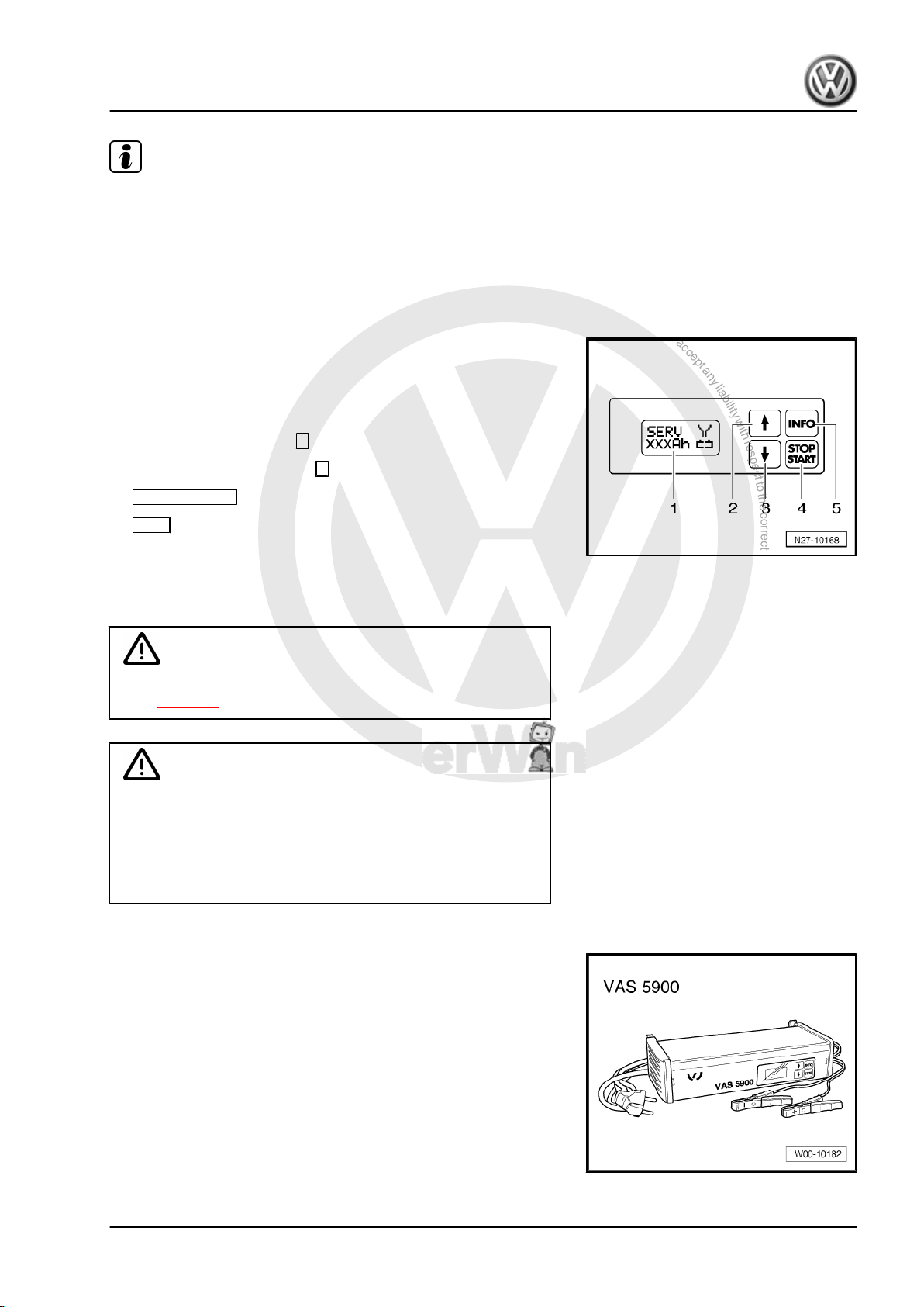
P
r
o
t
e
c
t
e
d
b
y
c
o
p
y
r
i
g
h
t
.
C
o
p
y
i
n
g
f
o
r
p
r
i
v
a
t
e
o
r
c
o
m
m
e
r
c
i
a
l
p
u
r
p
o
s
e
s
,
i
n
p
a
r
t
o
r
i
n
w
h
o
l
e
,
i
s
n
o
t
p
e
r
m
i
t
t
e
d
u
n
l
e
s
s
a
u
t
h
o
r
i
s
e
d
b
y
V
o
l
k
s
w
a
g
e
n
A
G
.
V
o
l
k
s
w
a
g
e
n
A
G
d
o
e
s
n
o
t
g
u
a
r
a
n
t
e
e
o
r
a
c
c
e
p
t
a
n
y
l
i
a
b
i
l
i
t
y
w
i
t
h
r
e
s
p
e
c
t
t
o
t
h
e
c
o
r
r
e
c
t
n
e
s
s
o
f
i
n
f
o
r
m
a
t
i
o
n
i
n
t
h
i
s
d
o
c
u
m
e
n
t
.
C
o
p
y
r
i
g
h
t
b
y
V
o
l
k
s
w
a
g
e
n
A
G
.
Note
♦
The effective charging current can be read directly on these
charging units.
♦
Observe ⇒ operating instructions for battery charger -VAS
5900- .
3.2.1 Description of battery charger -VAS
5900-
The battery charger -VAS 5900- is suitable for charging all 12V
batteries supplied by Volkswagen.
Battery charger -VAS 5900-
1 — Display
2 — Adjustment button „Up“ ↑
3 — Adjustment button „Down“ ↓
4 — START / STOP
5 — INFO
3.2.2 Charging battery with battery charger —
VAS 5900-
WARNING
Danger of injury! Observe warning notices and safety regula‐
tions ⇒ page 2 !
WARNING
Batteries where the magic eye is colourless or light yellow must
not be checked or charged. Do not slave/jump start the vehicle!
Danger of explosion when checking and charging or slave/
jump starting
These batteries must be renewed.
Special tools and workshop equipment required
♦ Battery charger -VAS 5900-
Bora 1999 ➤ , Bora Variant 1999 ➤ , CC 2010 ➤ , Eos 2006 ➤ , Golf 199 …
Electrical System, General Information — Edition 07.2010
3. Charging battery 31
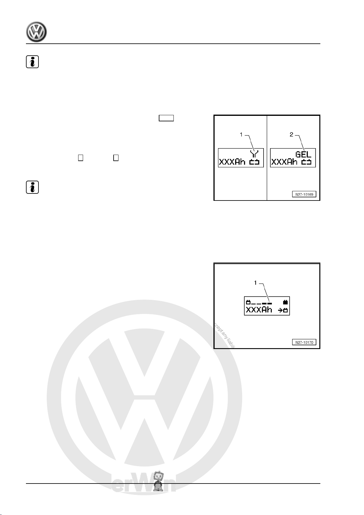
P
r
o
t
e
c
t
e
d
b
y
c
o
p
y
r
i
g
h
t
.
C
o
p
y
i
n
g
f
o
r
p
r
i
v
a
t
e
o
r
c
o
m
m
e
r
c
i
a
l
p
u
r
p
o
s
e
s
,
i
n
p
a
r
t
o
r
i
n
w
h
o
l
e
,
i
s
n
o
t
p
e
r
m
i
t
t
e
d
u
n
l
e
s
s
a
u
t
h
o
r
i
s
e
d
b
y
V
o
l
k
s
w
a
g
e
n
A
G
.
V
o
l
k
s
w
a
g
e
n
A
G
d
o
e
s
n
o
t
g
u
a
r
a
n
t
e
e
o
r
a
c
c
e
p
t
a
n
y
l
i
a
b
i
l
i
t
y
w
i
t
h
r
e
s
p
e
c
t
t
o
t
h
e
c
o
r
r
e
c
t
n
e
s
s
o
f
i
n
f
o
r
m
a
t
i
o
n
i
n
t
h
i
s
d
o
c
u
m
e
n
t
.
C
o
p
y
r
i
g
h
t
b
y
V
o
l
k
s
w
a
g
e
n
A
G
.
Note
The battery must have a temperature of at least 10 °C.
– Switch off ignition and all electrical consumers.
– Connect charger plug to battery charger. The last selected
type of battery will appear on display.
– Set battery to respective operating mode with INFO .
In the display the symbol -1- for „standard charge for wet batter‐
ies“ or symbol -2- for „standard charge for gel/absorbent glass
mat batteries“ will appear.
– Set battery capacity (Ah) of battery for charging using respec‐
tive button „Up“ ↑ or „Down“ ↓ .
– Connect red terminal clamp „+“ to positive terminal on battery.
Note
In vehicles with start/stop function and battery monitor control unit
-J367- fitted, black terminal clamp must be connected to body
earth. Connecting it to battery negative terminal will cause start/
stop system to malfunction.
– Connect black terminal clamp „-“ to negative terminal.
The charger unit recognises the voltage required for the connec‐
ted battery (6 V, 12 V or 24 V) and initiates the charging sequence.
At a charge condition of approx. 80 — 85 % the battery charger
switches to the „final charge“ mode. The fourth bar appears in
display -1-. The battery is ready for use.
Bora 1999 ➤ , Bora Variant 1999 ➤ , CC 2010 ➤ , Eos 2006 ➤ , Golf 199 …
Electrical System, General Information — Edition 07.2010
32 Rep. gr.27 — Starter, current supply, CCS
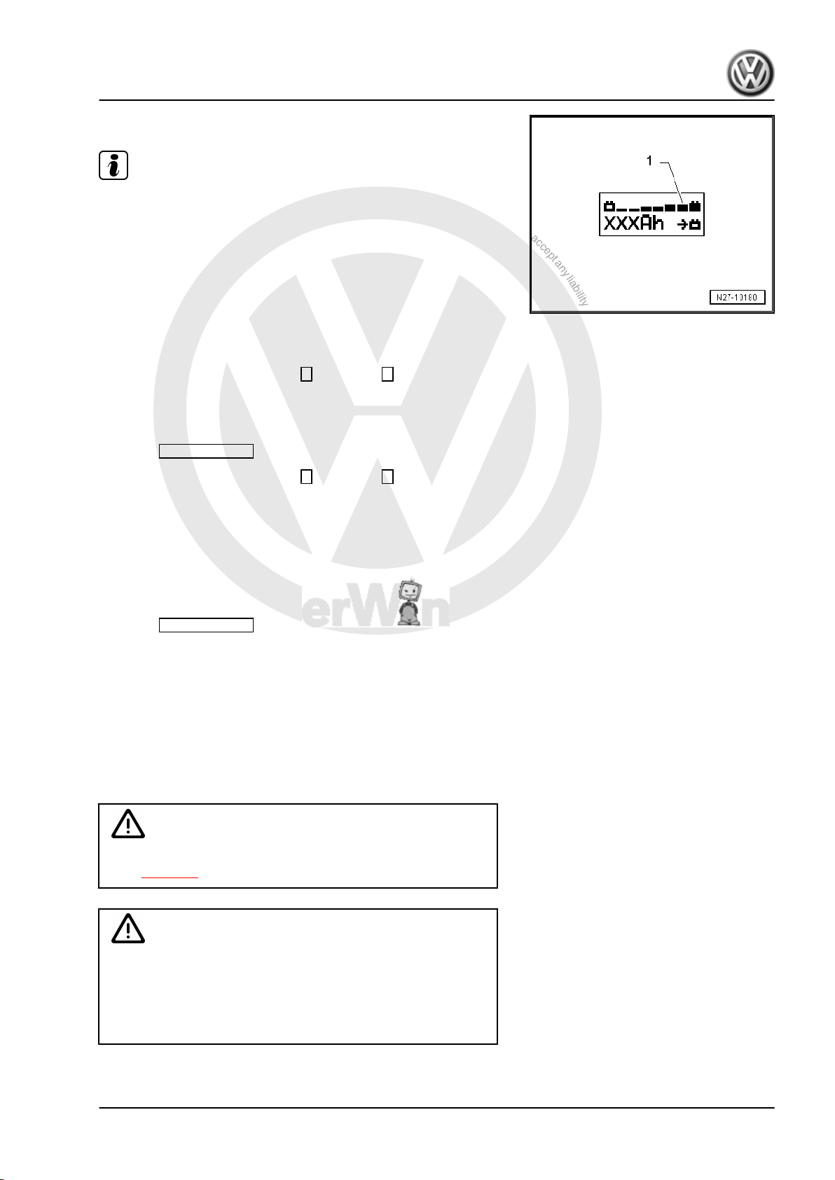
P
r
o
t
e
c
t
e
d
b
y
c
o
p
y
r
i
g
h
t
.
C
o
p
y
i
n
g
f
o
r
p
r
i
v
a
t
e
o
r
c
o
m
m
e
r
c
i
a
l
p
u
r
p
o
s
e
s
,
i
n
p
a
r
t
o
r
i
n
w
h
o
l
e
,
i
s
n
o
t
p
e
r
m
i
t
t
e
d
u
n
l
e
s
s
a
u
t
h
o
r
i
s
e
d
b
y
V
o
l
k
s
w
a
g
e
n
A
G
.
V
o
l
k
s
w
a
g
e
n
A
G
d
o
e
s
n
o
t
g
u
a
r
a
n
t
e
e
o
r
a
c
c
e
p
t
a
n
y
l
i
a
b
i
l
i
t
y
w
i
t
h
r
e
s
p
e
c
t
t
o
t
h
e
c
o
r
r
e
c
t
n
e
s
s
o
f
i
n
f
o
r
m
a
t
i
o
n
i
n
t
h
i
s
d
o
c
u
m
e
n
t
.
C
o
p
y
r
i
g
h
t
b
y
V
o
l
k
s
w
a
g
e
n
A
G
.
At a charge condition of 100 % all bars appear in display.
Note
♦
In the battery type „standard charge“ the parallel use of con‐
sumers while charging is possible. The charging period will be
longer.
♦
The battery charger will switch to maintenance mode after
about 1-7 hours, depending on type of battery. To achieve a
100 % charge the battery should remain connected for this
period.
Possible faults and fault rectification
1 — Displayed battery voltage is not as per nominal voltage:
– Press respective button „Up“ ↑ or „Down“ ↓ until charging
sequence starts.
2 — Displayed battery voltage is not as per nominal voltage –
charging sequence already started:
– Press START / STOP twice.
– Press respective button „Up“ ↑ or „Down“ ↓ until charging
sequence starts again.
3 — Battery charger does not detect a battery, when battery volt‐
age is less than 2 V:
Display remains unchanged.
The battery type and ampere hours (Ah) as set is displayed.
Ending battery charging sequence:
– Press START / STOP .
– Disconnect black terminal clamp „-“ of charger from negative
terminal.
– Disconnect red terminal clamp „+“ of charger from positive
terminal on battery.
– Pull charger plug out of battery charger.
3.2.3 Charging battery in service mode with
battery charger -VAS 5900-
WARNING
Danger of injury! Observe warning notices and safety regula‐
tions ⇒ page 2 !
Caution
The operating mode „service charge“ is not permitted on VW
vehicles as the voltage peaks will damage the onboard elec‐
tronics.
If there is a requirement to use „service charge“ the battery
must be disconnected from the onboard supply.
Bora 1999 ➤ , Bora Variant 1999 ➤ , CC 2010 ➤ , Eos 2006 ➤ , Golf 199 …
Electrical System, General Information — Edition 07.2010
3. Charging battery 33
 Loading…
Volkswagen Golf IV / Bora / Jetta с бензиновыми двигателями: AXP/BCA 1.4 л (1390 см³) 75 л.с./55 кВт, AKL/AEH 1.6 л (1595 см³) 101 л.с./74 кВт, AEG/APK 2.0 л (1984 см³) 115 л.с./85 кВт; Руководство по эксплуатации, техническому обслуживанию и ремонту, цветные фотографии, уход за автомобилем, неисправности и способы их устранения, технические характеристики, схемы электрооборудования, контрольные размеры кузова, устройство, диагностика, особенности конструкции. Практическое пособие Фольксваген Гольф 4 с кузовами пяти- и трехдверный хэтчбек и универсал, Бора и Джетта седан переднеприводные модели четвёртого поколения выпуска с 1997 по 2005 год
ЕСЛИ ВЫ ВИДИТЕ ОШИБКУ 406 Not Acceptable и не видите документ, то скорей всего у Вас IP РФ и его надо сменить, на любой другой страны, с помощью VPN ( Scribd и SlideShare блокируют посетителей с Российским IP).
Видео VW Golf IV/ Bora/ Jetta замена переднего бампера/ how to bumper removal и амортизационных стоек/ changing front struts
Volkswagen Golf Mark IV / Bora / Jetta общая информация (Фольксваген Гольф 4, Бора и Джетта 1997-2005)
ОПИСАНИЕ КОНСТРУКЦИИ
В книге рассмотрены устройство, техническое обслуживание и ремонт переднеприводных автомобилей VW Golf IV и Jetta/Bora с двигателями модели «АХР/ВСА» рабочим объемом 1390 см³, «AKL/ AEH» — объемом 1595 см³ и «AEG/ АРК» — объемом 1984 см³.
На всех двигателях установлена система питания с распределенным впрыском топлива и электронным блоком управления.
Автомобиль VW Golf IV — легковой, пятиместный, трех или пятидверный с кузовом хэтчбек, а также пятидверный универсал, выпускаемые с 1997 года. Автомобиль VW Jetta/Bora — пятиместный, четырехдверный седан или пятидверный универсал, выпускаемый с 1999 г. Кузов — цельнометаллический, несущей конструкции, сварной, полностью оцинкованный. По габаритным размерам автомобиль соответствует классу С. Автомобиль с передним поперечным расположением двигателя, пятиступенчатой механической или четырехступенчатой автоматической коробкой передач и приводом на передние колеса.
Автомобиль имеет независимую подвеску передних и полунезависимую подвеску задних колес. Рулевое управление типа шестерня-рейка с гидроусилителем. Тормозная система с диагональным распределением контуров, вакуумным усилителем и антиблокировочной системой АБС. Более подробно описание систем даны в соответствующих разделах книги.
В книге изложено описание работ по техническому обслуживанию и ремонту автомобилей Volkswagen Golf 4, Bora, Jetta 1997-2005 годов выпуска на базе готовых запасных частей в условиях гаражной мастерской. Все рабочие операции сопровождаются фотографиями и подробными комментариями, что позволяет экономить время, силы и средства, а также свести к минимуму риск повреждения техники. Для автомехаников, а также автомобилистов, занимающихся самостоятельным обслуживанием и ремонтом автомобилей.
СИСТЕМА ПИТАНИЯ ДВИГАТЕЛЯ 2,0 литра
Система питания двигателя автомобиля предназначена для хранения запаса топлива, очистки топлива и воздуха от посторонних примесей, подачи воздуха и топлива в цилиндры двигателя. Система питания состоит из топливного бака, электробензонасоса с датчиком указателя уровня топлива (топливного модуля), топливопроводов, топливного фильтра, топливной рампы с форсунками и трубкой подачи воздуха да обдува впускных клапанов, регулятора давления топлива, воздушного фильтра, шлангов подвода воздуха, дроссельного узла, ресивера, впускного трубопровода, системы подачи вторичного воздуха в выпускной коллектор (для двигателей с системой вторичного воздуха), а также системы улавливания паров топлива.
Воздух, поступающий в цилиндры двигателя, очищается от пыли воздушным фильтром.
Воздушный фильтр установлен в моторном отсеке. Фильтрующий элемент фильтра — сменный, изготовлен из специальной бумаги. Для замены фильтрующего элемента крышка фильтра выполнена съемной. Очищенный воздух проходит через корпус датчика массового расхода воздуха и по шлангу поступает к дроссельному узлу. В патрубке, соединяющем воздушный шланг и маслозаливную горловину двигателя, установлен нагревательный элемент системы вентиляции картерных газов.
Дроссельный узел закреплен болтами на фланце входного патрубка ресивера. Количество поступающего в цилиндры двигателя воздуха регулируется по воротной заслонкой, установленной на оси в корпусе дроссельного узла. Привод дроссельной заслонки тросовый, от педали газа и сервопривода блока управления заслонкой. Сервопривод блока управления заслонкой открывает и закрывает дроссельную заслонку при работе двигателя на холостом ходу и плавно закрывает заслонку при снятии ноги с педали «газа». При отсутствии электропитания страховочная пружина на холостом ходу устанавливает дроссельную заслонку в определенное положение. Блок управления заслонкой установлен на корпусе дроссельной заслонки и выполнен с ним как неразборный узел. Снимать крышку блока управления нельзя.
В корпусе дроссельной заслонки выполнен канал для охлаждающей жидкости. Резиновыми шлангами канал связан с системой охлаждения. Циркуляция охлаждающей жидкости через корпус дроссельной заслонки предотвращает обмерзание внутренних воздушных полостей корпуса зимой. В корпусе установлен штуцер для соединения с адсорбером. Воздух к впускным клапанам цилиндров двигателя подводится через ресивер и впускной трубопровод. Топливо из топливного бака по нагнетающему трубопроводу поступает в топливную рампу. Устройство системы подачи топлива для двигателя 2,0 л аналогично системе подачи топлива для двигателя 1,6 л и описано в соответствующем разделе (см. с. 168, «Описание конструкции»).
Топливная рампа представляет собой полую планку, через которую топливо подается к четырем закрепленным на ней форсункам. Каждая форсунка открывается по команде ЭБУ, при этом топливо впрыскивается в пространство над впускным клапаном, где смешивается с воздухом, поступающим из впускного трубопровода, и далее через открытый впускной клапан поступает в цилиндр двигателя. Для улучшения распыления топлива конструкция форсунки выполнена таким образом, что в пространство форсунки за ее клапаном подается дополнительное количество воздуха. Соединения рампы с форсунками, впускным трубопроводом и регулятором давления уплотнены резиновыми кольцами. Топливный насос создает давление в топливопроводе. Величина давления топлива в зависимости от разрежения воздуха во впускном тракте ограничивается регулятором давления, установленным на выходном патрубке топливной рампы. Избыток топлива из топливной рампы через клапан регулятора давления по возвратному трубопроводу направляется в топливный бак. Трубки нагнетающего трубопровода имеют черный цвет, возвратного трубопровода — синий.
Система подачи вторичного воздуха после запуска холодного двигателя (температура охлаждающей жидкости +5 — +33 °С) в течение 100 секунд и каждый раз после последующего запуска двигателя (при его температуре менее 96 °С) в течение 10 секунд нагнетает воздух в выпускной коллектор. Отработавшие газы при этом обогащаются кислородом, и происходит дожигание не сгоревших остатков топлива, в результате чего каталитический нейтрализатор прогревается быстрее. Система подачи вторичного воздуха включает в себя электрический насос, клапан подачи воздуха, электромагнитный клапан и соединительные воздушные шланги.
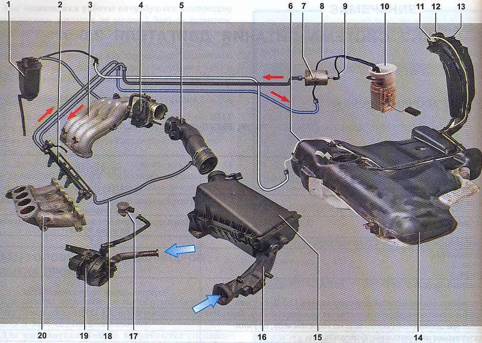
Детали системы питания: 1 — адсорбер; 2 — топливная рампа; 3 — ресивер; 4 — дроссельный узел; 5 — шланг подвода воздуха к корпусу дроссельной заслонки; 6 — трубопровод вентиляции бака; 7 -топливный фильтр; 8 — возвратный топливопровод; 9 — нагнетающий топливопровод; 10 — топливный модуль; 11 — предохранительный клапан; 12 — заливная горловина; 13 — воздушный клапан; 14 — топливный бак; 15 — воздушный фильтр; 16 — воздуховод; 17 — клапан вторичного воздуха*; 18 — трубка подачи воздуха; 19 — насос вторичного воздуха*; 20 — впускной трубопровод * Устанавливается на двигателе с системой вторичного воздуха
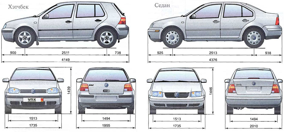
| № | Спецификация / Specs | Данные |
| Габариты (мм/mm) и масса (кг/kg) / Dimensions and Weight | ||
| 1 | Длина / Length | 4376 |
| 2 | Ширина (без/с зеркалами) / Width | 1735/2010 |
| 3 | Высота (загружен/пустой) / Height | 1446 |
| 4 | Колёсная база / Wheelbase | 2513 |
| 5 | Дорожный просвет (клиренс) / Ground clearance | 120 |
| 6 | Снаряжённая масса / Total (curb) weight | 1305 |
| Полная масса / Gross (max.) weight | 1780 | |
|
Двигатель / Engine |
||
| 7 | Тип / Engine Type, Code | Бензиновый, жидкостного охлаждения, четырехтактный, AEG |
| 8 | Количество цилиндров / Cylinder arrangement: Total number of cylinders, of valves | 4-цилиндровый, рядный, 8V, SOHC с верхним расположением одного распределительного вала |
| 9 | Диаметр цилиндра / Bore | 82.6 мм (3.25 in) |
| 10 | Ход поршня / Stroke | 92.7 мм (3.65 in) |
| 11 | Объём / Engine displacement | 1984 см³ (121.071 CID) |
| 12 | Система питания / Fuel supply, Aspiration | Распределенный впрыск топлива EFi Bosch Motronic ME 7.5 |
| Атмосферный | ||
| 13 | Степень сжатия / Compression ratio | 10.0:1 |
| 14 | Максимальная мощность / Max. output power kW (HP) at rpm | 85 кВт (115 л.с./113 bhp) при 5200 об/мин |
| 15 | Максимальный крутящий момент / Max. torque N·m at rpm | 165 Нм (122 ft·lb) при 2600 об/мин |
|
Трансмиссия / Transmission |
||
| 16 | Сцепление / Clutch type | Гидротрансформатор / Torque Converter |
| 17 | КПП / Transmission type | 01M АКПП 4 Автоматическая, четырёхступенчатая, гидромеханическая, адаптивная |
О Книге
- Название: Автомобили Volkswagen Golf 4, Bora, Jetta (1997-2005). Эксплуатация, обслуживание, ремонт. Иллюстрированное практическое пособие
- Бензиновые двигатели: AXP/BCA 1.4 л (1390 см³) 75 л.с./55 кВт, AKL/AEH 1.6 л (1595 см³) 101 л.с./74 кВт, AEG/APK 2.0 л (1984 см³) 115 л.с./85 кВт
- Выпуск с 1997 года
- Серия: «Я ремонтирую сам»
- Год издания: 2008
- Автор: Коллектив авторов
- Издательство: «Ассоциация независимых издателей»
- Формат: PDF
- Страниц в книге: 511
- Размер: 145.08 МБ
- Язык: Русский
- Количество электросхем: 29
