-
Contents
-
Table of Contents
-
Bookmarks
Quick Links
Installation Manual
TABLE OF CONTENTS
1. MOUNTING………………………………. 1-1
2.
WIRING …………………………………. 2-1
3.
All brand and product names are trademarks, registered trademarks or
service marks of their respective holders.
MARINE RADAR/ARPA
FAR-2117/2127/2817/2827
FAR-2117-BB/2127-BB
5.
INSTALLATION MATERIALS,
ACCESSORIES,SPARE PARTS …….. A-1
OUTLINE DRAWINGS ………………….D-1
www.furuno.co.jp
Comply with MSC.192(79)
EQUIPMENT………………………….. 4-1
Summary of Contents for Furuno FAR-2117
www.furuno.co.jp
All brand and product names are trademarks, registered trademarks or
service marks of their respective holders.
MARINE RADAR/ARPA
FAR-2117/2127/2817/2827
FAR-2117-BB/2127-BB
Installation Manual
Comply with MSC.192(79)
TABLE OF CONTENTS
SAFETY IINSTRUCTIONS ………………… i
EQUIPMENT LISTS ………………………….iii
SYSTEM CONFIGURATION ……………..vi
1. MOUNTING………………………………. 1-1
1.1 Antenna Unit……………………………1-1
1.2 Monitor Unit…………………………….1-6
1.3 Control Unit …………………………..1-10
1.4 Processor Unit……………………….1-15
2. WIRING …………………………………. 2-1
2.1 Interconnection………………………..2-1
2.2 Antenna Unit……………………………2-2
2.3 Monitor Unit…………………………….2-6
2.4 Processor Unit…………………………2-7
2.5 Changing AC Power Specification of
Processor Unit ……………………..2-12
3. SETTING AND ADJUSTMENT …. 3-1
3.1 DIP Switch Setting …………………..3-1
3.2 Initializing Tuning……………………..3-2
3.3 Heading Alignment …………………..3-3
3.4 Adjustment Sweep Timing…………3-6
3.5 Suppressing Main Bang ……………….3-7
3.6 Other Settings …………………………3-8
3.7 Dual Radar Display
(non IMO-type only) ………………3-16
4. INSTALLING
OPTIONAL
EQUIPMENT………………………….. 4-1
4.1 Gyro Converter GC-10 ……………..4-1
4.2 Memory Card Interface Unit…………..4-9
4.3 DVI-RGB Conversion Kit
(for VDR connection) ………………4-12
4.4 Performance Monitor PM-31 ……4-15
4.5 BNC Connector Converter ………4-17
4.6 Junction Box………………………….4-18
5. INPUT/OUTPUT
DATA ……………. 5-1
INSTALLATION MATERIALS,
ACCESSORIES,SPARE PARTS …….. A-1
OUTLINE DRAWINGS ………………….D-1
INTERCONNECTION DIAGRAMS … S-1
Скачать файл PDF «Furuno FAR-2117-BB Инструкция по эксплуатации» (5.57 Mb)
Популярность:
1923 просмотры
Подсчет страниц:
135 страницы
Тип файла:
Размер файла:
5.57 Mb
![]()
MARINE RADAR/ARPA
FAR-28×7 Series


 FAR-21×7(-BB) Series

9-52 Ashihara-cho,
Nishinomiya 662-8580, JAPAN
|
Telephone : |
0798-65-2111 |
|
|
Fax |
:: |
0798-65-4200 |
|
All rights reserved. |
Printed in Japan |
Pub. No. OME-35190
(( DAMI )) FAR-2107/2807 SER.
Your Local Agent/Dealer
FIRST EDITION : JAN.. 2004
C ::AUG.. 25, 2004
*00014745202*
*00014745202*
* 0 0 0 1 4 7 4 5 2 0 2 *
*OME35190C00*
*OME35190C00*
* O M E 3 5 1 9 0 C 0 0 *

SAFETY INSTRUCTIONS
 WARNING
Radio Frequency Radiation Hazard
The radar antenna emits electromagnetic radio frequency (RF) energy which can be harmful, particularly to your eyes. Never look directly into the antenna aperture from a close distance while the radar is in operation or expose yourself to the transmitting antenna at a close distance.
Distances at which RF radiation levels of 100 and 10 W/m2 exist are given in the table below.
Note: If the antenna unit is installed at a close distance in front of the wheel house, your administration may require halt of transmission within a certain sector of antenna revolution. This is possible. Ask your FURUNO representative or dealer to provide this feature.
|
Distance to |
Distance to |
||||
|
Model3 |
TR unit |
Magnetron |
Antenna1 |
100 W/m2 |
10 W/m2 |
|
point |
point |
||||
|
FAR-2827/2127 |
RTR-079 |
MG5436 |
XN12AF |
0.80 m |
11.20 m |
|
FAR-2827/2127 |
RTR-079 |
MG5436 |
XN20AF |
0.40 m |
8.60 m |
|
FAR-2827/2127 |
RTR-079 |
MG5436 |
XN24AF |
0.20 m |
5.80 m |
|
FAR-2817/2117 |
RTR-078 |
MG40102 |
XN12AF |
0.30 m |
4.20 m |
|
FAR-2817/2117 |
RTR-078 |
MG40102 |
XN20AF |
0.10 m |
3.00 m |
|
FAR-2817/2117 |
RTR-078 |
MG40102 |
XN24AF |
— |
2.40 m |
|
FAR-2137S |
RTR-080 |
MG5223F |
SN30AF |
||
|
FAR-2137S |
RTR-080 |
MG5223F |
SN36AF |
||
|
FAR-2827W |
RTR-081 |
MG5436 |
XN20AF |
||
|
FAR-2827W |
RTR-081 |
MG5436 |
XN24AF |
||
|
FAR-2837S |
RTR-080 |
MG5223F |
SN30AF |
||
|
FAR-2837S |
RTR-080 |
MG5223F |
SN36AF |
||
|
FAR-2837SW |
RTR-082 |
MG5223F |
SN30AF |
||
|
FAR-2837SW |
RTR-082 |
MG5223F |
SN36AF |
||
|
1 XN12AF: 4 ft |
XN20AF: 6.5 ft XN24AF: 8 ft |
||||
|
SN30AF: 10 ft |
SN36AF: 12 ft |
2Or MAF1425B
3FAR-2117/2127/2137S available in blackbox configuration.
i
SAFETY INSTRUCTIONS
 WARNING
ELECTRICAL SHOCK HAZARD
Do not open the equipment.
Only qualified personnel should work inside the equipment.
Turn off the radar power switch before servicing the antenna unit. Post a warning sign near the switch indicating it should not be turned on while the antenna unit is being serviced.
Prevent the potential risk of being struck by the rotating antenna and exposure to RF radiation hazard.
Wear a safety belt and hard hat when working on the antenna unit.
Serious injury or death can result if someone falls from the radar antenna mast.
Do not disassemble or modify the equipment.
Fire, electrical shock or serious injury can result.
Immediately turn off the power at the ship’s mains switchboard if water leaks into the equipment or the equipment is emitting smoke or fire.
Continued use can cause fatal damage to the equipment.
 WARNING
Use the proper fuse.
Use of a wrong fuse can result in damage to the equipment or cause fire.
Keep heater away from equipment.
Heat can alter equipment shape and melt the power cord, which can cause fire or electrical shock.
Do not place liquid-filled containers near the equipment.
Fire or electrical shock can result if a liquid spills into the equipment.
Do not operate the equipment with wet hands.
Electrical shock can result.
Before servicing the radar, turn off the appropriate external breaker.
Power is not removed from the radar simply by turning off its power switch.
ii

 WARNING
No one navigational aid should be relied upon for the safety of vessel and crew. The navigator has the responsibility to check all aids available to confirm position. Electronic aids are not
a substitute for basic navigational principles and common sense.
•This ARP automatically tracks automatically or manually acquired radar targets and calculates their courses and speeds, indicating them by vectors. Since the data generated by the auto plotter are based on what radar targets are selected, the radar must always be optimally tuned for use with the auto plotter, to ensure required targets will not be lost or unwanted targets such as sea returns and noise will not be acquired and tracked.
•A target does not always mean a landmass, reef, ships or other surface vessels but can imply returns from sea surface and clutter. As the level of clutter changes with environment, the operator should properly adjust the A/C SEA, A/C RAIN and GAIN controls to be sure target echoes are not eliminated from the
radar screen.
SAFETY INSTRUCTIONS
 CAUTION
The plotting accuracy and response of this ARP meets IMO standards. Tracking accuracy is affected by the following:
•Tracking accuracy is affected by course change. One to two minutes is required to restore vectors to full accuracy after an abrupt course change. (The actual amount depends on gyrocompass specifications.)
•The amount of tracking delay is inversely proportional to the relative speed of the target. Delay is on the order of 15—30 seconds for high relative speed; 30—60 seconds for low relative speed.
The data generated by ARP, AIS and video plotter are intended for reference only.
Refer to official nautical charts for detailed and up-to-date information.
iii
SAFETY INSTRUCTIONS
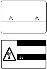
WARNING LABEL
Warning labels are attached to the equipment. Do not remove any label. If a label is missing or damaged, contact a FURUNO agent or dealer about replacement.
 WARNING
To avoid electrical shock, do not remove cover. No user-serviceable parts inside.

 WARNING
Radiation hazard. Only qualified personnel should work inside scanner. Confirm that TX has stopped before opening scanner.
DISPLAY UNIT, PROCESSOR UNIT
Name: Warning Label (1)
Type: 86-003-1011-0
Code No.: 100-236-230
ANTENNA UNIT
Name: Radiation Warning Label
Type: 03-142-3201-0
Code No.: 100-266-890
iv
TABLE OF CONTENTS
|
…………………………………………………………………………………………..FOREWORD |
xi |
||
|
PROGRAM NUMBER ……………………………………………………………………………. |
xiii |
||
|
SYSTEM CONFIGURATION…………………………………………………………………… |
xiv |
||
|
SPECIFICATIONS………………………………………………………………………………. |
SP-1 |
||
|
1 RADAR OPERATION………………………………………………………………………… |
1-1 |
||
|
1.1 |
Turning on the Power……………………………………………………………………………………. |
1-1 |
|
|
1.2 |
Transmitter ON ……………………………………………………………………………………………. |
1-1 |
|
|
1.3 |
Control Unit…………………………………………………………………………………………………. |
1-3 |
|
|
1.4 |
Main Menu………………………………………………………………………………………………….. |
1-5 |
|
|
1.5 |
Operation Using the On-Screen Boxes……………………………………………………………. |
1-7 |
|
|
1.6 |
Cursor Menu……………………………………………………………………………………………… |
1-10 |
|
|
1.7 |
Monitor Brilliance ……………………………………………………………………………………….. |
1-11 |
|
|
1.8 |
Choosing the Display Mode …………………………………………………………………………. |
1-12 |
|
|
1.9 |
On-Screen Boxes and Markers…………………………………………………………………….. |
1-13 |
|
|
1.10 |
Tuning the Receiver……………………………………………………………………………………. |
1-15 |
|
|
1.10.1 Choosing the tuning method……………………………………………………………….. |
1-15 |
||
|
1.10.2 Initializing tuning……………………………………………………………………………….. |
1-15 |
||
|
1.10.3 Automatic tuning……………………………………………………………………………….. |
1-16 |
||
|
1.10.4 Manual tuning…………………………………………………………………………………… |
1-16 |
||
|
1.11 |
Aligning Heading with Gyrocompass……………………………………………………………… |
1-17 |
|
|
1.12 |
Presentation Modes……………………………………………………………………………………. |
1-18 |
|
|
1.12.1 Choosing presentation mode………………………………………………………………. |
1-18 |
||
|
1.12.2 Description of presentation modes ………………………………………………………. |
1-19 |
||
|
1.13 |
Entering Own Ship’s Speed …………………………………………………………………………. |
1-22 |
|
|
1.13.1 Automatic speed input by log or GPS navigator …………………………………….. |
1-22 |
||
|
1.13.2 Manual speed input…………………………………………………………………………… |
1-23 |
||
|
1.14 |
Choosing the Range Scale ………………………………………………………………………….. |
1-24 |
|
|
1.15 |
Choosing the Pulselength……………………………………………………………………………. |
1-25 |
|
|
1.15.1 Choosing pulselength………………………………………………………………………… |
1-25 |
||
|
1.15.2 Choosing pulselength………………………………………………………………………… |
1-26 |
||
|
1.16 |
Adjusting the Sensitivity………………………………………………………………………………. |
1-27 |
|
|
1.17 |
Suppressing Sea Clutter……………………………………………………………………………… |
1-28 |
|
|
1.17.1 Choosing method of adjustment………………………………………………………….. |
1-28 |
||
|
1.17.2 Automatic adjustment by the A/C SEA control ……………………………………….. |
1-28 |
||
|
1.17.3 Manual adjustment of A/C SEA …………………………………………………………… |
1-29 |
||
|
1.18 |
Suppressing Rain Clutter…………………………………………………………………………….. |
1-30 |
|
|
1.18.1 Turning AUTO RAIN on or off ……………………………………………………………… |
1-30 |
||
|
1.18.2 Adjusting A/C RAIN …………………………………………………………………………… |
1-31 |
||
|
1.19 |
Interference Rejector ………………………………………………………………………………….. |
1-32 |
|
|
1.20 |
Measuring the Range………………………………………………………………………………….. |
1-34 |
|
|
1.20.1 Turning range rings on/off…………………………………………………………………… |
1-34 |
||
|
1.20.2 Measuring range by the variable range marker (VRM) ……………………………. |
1-35 |
||
|
1.21 |
Measuring the Bearing………………………………………………………………………………… |
1-37 |
|
|
1.21.1 Measuring the bearing……………………………………………………………………….. |
1-37 |
v
|
TABLE OF CONTENTS |
||
|
1.21.2 Choosing true or relative bearing ………………………………………………………… |
1-39 |
|
|
1.22 |
Collision Assessment by Offset EBL……………………………………………………………… |
1-40 |
|
1.22.1 How to assess risk of collision by the offset EBL……………………………………. |
1-40 |
|
|
1.22.2 Choosing point of reference for origin point of offset EBL………………………… |
1-41 |
|
|
1.23 |
Measuring Range and Bearing Between Two Targets ……………………………………… |
1-42 |
|
1.24 |
Setting a Target Alarm………………………………………………………………………………… |
1-43 |
|
1.24.1 How to set a target alarm zone …………………………………………………………… |
1-43 |
|
|
1.24.2 Acknowledging the target alarm………………………………………………………….. |
1-44 |
|
|
1.24.3 Deactivating a target alarm ………………………………………………………………… |
1-44 |
|
|
1.24.4 Target alarm attributes ………………………………………………………………………. |
1-45 |
|
|
1.25 |
Off-Centering the Display ……………………………………………………………………………. |
1-46 |
|
1.26 |
Echo Stretch……………………………………………………………………………………………… |
1-47 |
|
1.27 |
Echo Averaging …………………………………………………………………………………………. |
1-48 |
|
1.28 |
Target Trails………………………………………………………………………………………………. |
1-49 |
|
1.28.1 True or relative trails …………………………………………………………………………. |
1-49 |
|
|
1.28.2 Trail time…………………………………………………………………………………………. |
1-50 |
|
|
1.28.3 Trail gradation………………………………………………………………………………….. |
1-50 |
|
|
1.28.4 Resetting target trails………………………………………………………………………… |
1-51 |
|
|
1.28.5 Trail copy ………………………………………………………………………………………… |
1-51 |
|
|
1.28.6 Trail level ………………………………………………………………………………………… |
1-52 |
|
|
1.28.7 Narrow trails ……………………………………………………………………………………. |
1-52 |
|
|
1.28.8 Canceling trails ………………………………………………………………………………… |
1-52 |
|
|
1.29 |
Parallel Index Lines……………………………………………………………………………………. |
1-53 |
|
1.29.1 Displaying, erasing parallel index lines…………………………………………………. |
1-53 |
|
|
1.29.2 Adjusting index line orientation, index line interval …………………………………. |
1-54 |
|
|
1.29.3 Index line bearing reference……………………………………………………………….. |
1-54 |
|
|
1.29.4 Choosing maximum number of index lines to display……………………………… |
1-55 |
|
|
1.29.5 Index line mode ……………………………………………………………………………….. |
1-55 |
|
|
1.30 |
Origin Mark……………………………………………………………………………………………….. |
1-56 |
|
1.30.1 Entering origin marks………………………………………………………………………… |
1-56 |
|
|
1.30.2 Origin mark stabilization…………………………………………………………………….. |
1-58 |
|
|
1.30.3 Deleting individual origin marks…………………………………………………………… |
1-58 |
|
|
1.31 |
Zoom……………………………………………………………………………………………………….. |
1-59 |
|
1.32 |
Markers ……………………………………………………………………………………………………. |
1-60 |
|
1.32.1 Heading marker and heading line ……………………………………………………….. |
1-60 |
|
|
1.32.2 Stern marker……………………………………………………………………………………. |
1-60 |
|
|
1.32.3 North marker……………………………………………………………………………………. |
1-60 |
|
|
1.32.4 Own ship symbol ……………………………………………………………………………… |
1-61 |
|
|
1.33 |
Automatic Picture Setup According to Navigation Purpose……………………………….. |
1-62 |
|
1.33.1 Choosing a picture setup option………………………………………………………….. |
1-63 |
|
|
1.33.2 Restoring default picture setup options ………………………………………………… |
1-64 |
|
|
1.33.3 User-programmable picture setups……………………………………………………… |
1-65 |
|
|
1.34 |
Programming Function Keys ……………………………………………………………………….. |
1-67 |
|
1.34.1 Activating a function key ……………………………………………………………………. |
1-67 |
|
|
1.34.2 Programming the functions keys…………………………………………………………. |
1-67 |
|
|
1.35 |
Ship’s Position…………………………………………………………………………………………… |
1-71 |
|
1.36 |
Noise Rejector…………………………………………………………………………………………… |
1-72 |
|
1.37 |
Suppressing Second-trace Echoes ………………………………………………………………. |
1-73 |
vi
|
TABLE OF CONTENTS |
||||
|
1.38 |
Adjusting Brilliance of Screen Data ………………………………………………………………… |
1-74 |
||
|
1.39 |
Watch Alarm ……………………………………………………………………………………………….. |
1-75 |
||
|
1.40 |
Setting Up Nav Data…………………………………………………………………………………….. |
1-76 |
||
|
1.41 |
Text Window Setup………………………………………………………………………………………. |
1-78 |
||
|
1.42 |
Customizing Operation…………………………………………………………………………………. |
1-80 |
||
|
1.43 |
Alarms ……………………………………………………………………………………………………….. |
1-82 |
||
|
1.43.1 Alarm description ……………………………………………………………………………….. |
1-82 |
|||
|
1.43.2 Outputting alarm signal……………………………………………………………………….. |
1-84 |
|||
|
1.44 |
Choosing the Antenna, Displaying Antenna Information ……………………………………. |
1-85 |
||
|
1.44.1 Choosing the antenna…………………………………………………………………………. |
1-85 |
|||
|
1.44.2 Displaying antenna information ……………………………………………………………. |
1-86 |
|||
|
1.45 |
Cursor Data ………………………………………………………………………………………………… |
1-87 |
||
|
1.46 |
Performance Monitor……………………………………………………………………………………. |
1-88 |
||
|
1.46.1 Activating, deactivating the performance monitor……………………………………. |
1-88 |
|||
|
1.46.2 Checking radar performance ……………………………………………………………….. |
1-88 |
|||
|
1.47 |
Wiper |
…………………………………………………………………………………………………………. |
1-90 |
|
|
1.48 |
Own Ship Symbol………………………………………………………………………………………… |
1-91 |
||
|
1.49 |
Color ……………………………………………………………………………….and Brilliance Sets |
1-92 |
||
|
1.49.1 …………………………………………………………..Choosing color and brilliance set |
1-92 |
|||
|
1.49.2 ………………………………………………………….Presetting color and brilliance set |
1-92 |
|||
|
1.50 |
Reference ………………………………………………………………………Point for CPA/TCPA |
1-94 |
||
|
1.51 |
Switching ………………………………………………………………………Hub HB-100 (option) |
1-95 |
||
|
2 |
RADAR OBSERVATION ……………………………………………………………………. |
2-1 |
||
|
2.1 |
General………………………………………………………………………………………………………… |
2-1 |
||
|
2.1.1 ………………………………………………………………Minimum and maximum ranges |
2-1 |
|||
|
2.2 |
False …………………………………………………………………………………………………Echoes |
2-3 |
||
|
2.3 |
SART ………………………………………………………….(Search and Rescue Transponder) |
2-5 |
||
|
2.3.1 …………………………………………………………………………………. |
SART description |
2-5 |
||
|
2.3.2 ………………………………………………Showing SART marks on the radar display |
2-6 |
|||
|
2.3.3 ……………………………………………………….General remarks on receiving SART |
2-7 |
|||
|
2.4 |
RACON ……………………………………………………………………………………………………….. |
2-8 |
||
|
3 |
ARP OPERATION …………………………………………………………………………….. |
3-1 |
||
|
3.1 |
Usage …………………………………………………………………………………………Precautions |
3-1 |
||
|
3.2 |
Controls …………………………………………………………………………………………….for ARP |
3-2 |
||
|
3.3 |
Activating, ……………………………………………………………………………Deactivating ARP |
3-3 |
||
|
3.4 |
Entering ……………………………………………………………………………..Own Ship’s Speed |
3-3 |
||
|
3.4.1 …………………………………………………………………. |
Echo — referenced speed input |
3-3 |
||
|
3.5 |
Automatic ……………………………………………………………………………………..Acquisition |
3-5 |
||
|
3.5.1 ………………………………………………………………………. |
Enabling auto acquisition |
3-5 |
||
|
3.5.2 ……………………….Terminating tracking of targets (including reference targets) |
3-6 |
|||
|
3.6 |
Manual …………………………………………………………………………………………Acquisition |
3-7 |
||
|
3.6.1 ………………………………………………………Setting manual acquisition conditions |
3-7 |
|||
|
3.6.2 …………………………………………………………………….Manually acquiring a target |
3-7 |
|||
|
3.7 |
ARP Symbols …………………………………………………………and ARP Symbol Attributes |
3-9 |
||
|
3.7.1 ………………………………………………………………………………………. |
ARP symbols |
3-9 |
||
|
3.7.2 …………………………………………………………………………. |
ARP symbol brilliance |
3-10 |
||
|
3.7.3 ……………………………………………………………………ARP symbol color and size |
3-11 |
vii
|
TABLE OF CONTENTS |
|||
|
3.8 |
Displaying Target Data ……………………………………………………………………………….. |
3-12 |
|
|
3.8.1 Displaying individual target data………………………………………………………….. |
3-12 |
||
|
3.8.2 |
Target list ………………………………………………………………………………………… |
3-14 |
|
|
3.9 |
Vector Modes ……………………………………………………………………………………………. |
3-16 |
|
|
3.9.1 |
Description of vectors ……………………………………………………………………….. |
3-16 |
|
|
3.9.2 Vector motion and length …………………………………………………………………… |
3-17 |
||
|
3.10 |
Past Position Display………………………………………………………………………………….. |
3-18 |
|
|
3.10.1 Displaying and erasing past position points, choosing past position |
|||
|
plot interval ……………………………………………………………………………………… |
3-18 |
||
|
3.10.2 Past position display attributes……………………………………………………………. |
3-19 |
||
|
3.11 |
Set and Drift ……………………………………………………………………………………………… |
3-20 |
|
|
3.12 |
Setting CPA/TCPA Alarm Ranges…………………………………………………………………. |
3-21 |
|
|
3.12.1 Setting CPA/TCPA alarm ranges…………………………………………………………. |
3-21 |
||
|
3.12.2 Acknowledging CPA/TCPA alarm………………………………………………………… |
3-22 |
||
|
3.13 |
Setting a Guard Zone …………………………………………………………………………………. |
3-23 |
|
|
3.13.1 Activating the guard zone…………………………………………………………………… |
3-23 |
||
|
3.13.2 Sleeping, deactivating a guard zone ……………………………………………………. |
3-24 |
||
|
3.13.3 Acknowledging the guard zone alarm ………………………………………………….. |
3-24 |
||
|
3.13.4 Guard zone reference……………………………………………………………………….. |
3-25 |
||
|
3.13.5 Guard zone shape and stabilization …………………………………………………….. |
3-25 |
||
|
3.14 |
Operational Warnings…………………………………………………………………………………. |
3-26 |
|
|
3.15 |
Trial Maneuver ………………………………………………………………………………………….. |
3-28 |
|
|
3.15.1 Types of trial maneuvers……………………………………………………………………. |
3-28 |
||
|
3.15.2 Performing a trial maneuver……………………………………………………………….. |
3-29 |
||
|
3.15.3 Terminating a trial maneuver………………………………………………………………. |
3-31 |
||
|
3.16 |
ARP Performance Test ……………………………………………………………………………….. |
3-32 |
|
|
3.17 |
Criteria for Selecting Targets for Tracking………………………………………………………. |
3-34 |
|
|
3.18 |
Factors Affecting ARP Functions ………………………………………………………………….. |
3-36 |
|
|
4 AIS OPERATION………………………………………………………………………………. |
4-1 |
||
|
4.1 |
Controls for AIS …………………………………………………………………………………………… |
4-1 |
|
|
4.2 |
Enabling/Disabling the AIS ……………………………………………………………………………. |
4-2 |
|
|
4.3 |
Turning AIS Display On/Off……………………………………………………………………………. |
4-3 |
|
|
4.4 |
Setting Up for a Voyage………………………………………………………………………………… |
4-4 |
|
|
4.5 |
Activating Targets ………………………………………………………………………………………… |
4-6 |
|
|
4.5.1 |
Activating specific target ……………………………………………………………………… |
4-6 |
|
|
4.5.2 |
Activating all targets……………………………………………………………………………. |
4-6 |
|
|
4.6 |
Sleeping Targets………………………………………………………………………………………….. |
4-7 |
|
|
4.6.1 |
Sleeping an AIS target ………………………………………………………………………… |
4-7 |
|
|
4.6.2 |
Sleeping all AIS targets……………………………………………………………………….. |
4-7 |
|
|
4.7 |
Displaying Target Data …………………………………………………………………………………. |
4-8 |
|
|
4.7.1 |
Basic data…………………………………………………………………………………………. |
4-8 |
|
|
4.7.2 |
Detailed target data…………………………………………………………………………….. |
4-9 |
|
|
4.8 |
AIS Symbol Attributes…………………………………………………………………………………. |
4-10 |
|
|
4.8.1 |
AIS symbol brilliance…………………………………………………………………………. |
4-10 |
|
|
4.8.2 AIS symbol size and color…………………………………………………………………… |
4-11 |
viii
|
TABLE OF CONTENTS |
||
|
4.9 |
Past Position Display ………………………………………………………………………………….. |
4-12 |
|
4.9.1 |
Displaying and erasing past position points, choosing past position |
|
|
4-12 |
||
|
4.9.2 |
4-13 |
|
|
4.10 |
Lost Target………………………………………………………………………………………………… |
4-14 |
|
4.11 |
ROT Setting………………………………………………………………………………………………. |
4-15 |
|
4.12 |
Fusion of ARP and AIS Targets…………………………………………………………………….. |
4-16 |
|
4.13 |
Own Ship’s Data ………………………………………………………………………………………… |
4-18 |
|
4.14 |
Messages …………………………………………………………………………………………………. |
4-19 |
|
4.14.1 Creating, saving a message ……………………………………………………………….. |
4-19 |
|
|
4.14.2 Transmitting a message …………………………………………………………………….. |
4-20 |
|
|
4.14.3 Viewing AIS messages………………………………………………………………………. |
4-21 |
|
|
4.15 |
AIS System Messages………………………………………………………………………………… |
4-23 |
|
5 VIDEO PLOTTER OPERATION………………………………………………………….. |
5-1 |
|
|
5.1 |
General………………………………………………………………………………………………………. |
5-1 |
|
5.2 |
Display Modes …………………………………………………………………………………………….. |
5-1 |
|
5.3 |
Presentation Modes……………………………………………………………………………………… |
5-2 |
|
5.4 |
Radar Map………………………………………………………………………………………………….. |
5-3 |
|
5.4.1 |
5-3 |
|
|
5.4.2 |
5-4 |
|
|
5.5 |
Erasing Radar Map Marks and Lines………………………………………………………………. |
5-6 |
|
5.5.1 |
5-6 |
|
|
5.5.2 |
5-7 |
|
|
5.6 |
Radar Map Corrections…………………………………………………………………………………. |
5-8 |
|
5.6.1 |
5-8 |
|
|
5.6.2 |
5-8 |
|
|
5.7 |
Chart Cards ………………………………………………………………………………………………… |
5-9 |
|
5.7.1 |
5-9 |
|
|
5.7.2 |
5-10 |
|
|
5.7.3 |
5-10 |
|
|
5.7.4 |
5-11 |
|
|
5.8 |
Hiding/Showing Graphics on the Video Plotter Display …………………………………….. |
5-12 |
|
5.9 |
Track |
5-13 |
|
5.9.1 |
5-13 |
|
|
5.9.2 ……………………………………………………………………. |
5-14 |
|
|
5.9.3 ………………………………………………………………………….. |
5-14 |
|
|
5.9.4 ……………………………………………………………………………………. |
5-15 |
|
|
5.10 |
Marks …………………………………………………………………………………………and Lines |
5-16 |
|
5.10.1 …………………………………………………………………..Inscribing marks and lines |
5-16 |
|
|
5.11 |
Erasing ……………………………………………………………………………..Marks and Lines |
5-18 |
|
5.11.1 ……………………………………………………………..Erasing individual marks/lines |
5-18 |
|
|
5.11.2 ………………………………………………………………….Erasing all marks and lines |
5-19 |
|
|
5.12 |
Waypoints…………………………………………………………………………………………………. |
5-20 |
|
5.12.1 …………………………………………………………………………….Entering waypoints |
5-20 |
|
|
5.12.2 ……………………………………………..Editing, erasing waypoints from the menu |
5-23 |
|
|
5.12.3 ……………………………………………………………………………..Erasing waypoints |
5-24 |
ix
|
TABLE OF CONTENTS |
||
|
5.12.4 Waypoint list ………………………………………………………………………………………. |
5-25 |
|
|
5.12.5 Displaying waypoint name and number………………………………………………….. |
5-26 |
|
|
5.13 |
Nav Lines ……………………………………………………………………………………………………. |
5-27 |
|
5.13.1 Entering new nav line ………………………………………………………………………….. |
5-27 |
|
|
5.13.2 Editing nav lines …………………………………………………………………………………. |
5-28 |
|
|
5.13.3 Nav line list ………………………………………………………………………………………… |
5-29 |
|
|
5.13.4 Erasing nav lines ………………………………………………………………………………… |
5-30 |
|
|
5.13.5 Setting up nav lines …………………………………………………………………………….. |
5-31 |
|
|
5.13.6 Displaying nav line, waypoint mark ……………………………………………………….. |
5-33 |
|
|
5.14 |
Recording Data ……………………………………………………………………………………………. |
5-35 |
|
5.14.1 Initializing memory (RAM) cards……………………………………………………………. |
5-35 |
|
|
5.14.2 Recording data …………………………………………………………………………………… |
5-36 |
|
|
5.15 |
Replaying Data…………………………………………………………………………………………….. |
5-38 |
|
5.16 |
Deleting Files ………………………………………………………………………………………………. |
5-39 |
|
6 MAINTENANCE, TROUBLESHOOTING……………………………………………… |
6-1 |
|
|
6.1 |
Periodic Maintenance Schedule……………………………………………………………………….. |
6-2 |
|
6.2 |
Life Expectancy of Major Parts ………………………………………………………………………… |
6-3 |
|
6.3 |
Replacing the Fuse ………………………………………………………………………………………… |
6-3 |
|
6.4 |
Replacement of Battery on GC Board……………………………………………………………….. |
6-4 |
|
6.5 |
Trackball Maintenance ……………………………………………………………………………………. |
6-4 |
|
6.6 |
Easy Troubleshooting……………………………………………………………………………………… |
6-5 |
|
6.7 |
Advanced-level Troubleshooting………………………………………………………………………. |
6-6 |
|
6.8 |
Diagnostics……………………………………………………………………………………………………. |
6-9 |
|
6.9 |
System Messages………………………………………………………………………………………… |
6-12 |
|
APPENDIX ………………………………………………………………………………………… |
AP-1 |
|
|
1. Menu Tree ……………………………………………………………………………………………………… |
AP-1 |
|
|
2. Digital Interface……………………………………………………………………………………………….. |
AP-8 |
|
|
3. Parts Lists and Parts Location…………………………………………………………………………. |
AP-29 |
|
|
4. Longitude Error Table (on 96 nm range scale) …………………………………………………… |
AP-45 |
|
|
INDEX |
……………………………………………………………………………………………….. |
IN-1 |
Declaration of conformity
x

FOREWORD
A Word to the Owner of the FAR-28×7/FAR-21×7(-BB)
Congratulations on your choice of the FURUNO FAR-28×7/FAR-21×7(-BB) Series Radar. We are confident you will see why FURUNO has become synonymous with quality and reliability.
For over 50 years FURUNO Electric Company has enjoyed an enviable reputation for innovative and dependable marine electronics equipment. This dedication to excellence is furthered by our extensive global network of agents and dealers.
Your radar is designed and constructed to meet the rigorous demands of the marine environment. However, no machine can perform its intended function unless installed, operated and maintained properly. Please carefully read and follow the recommended procedures for operation and maintenance.
We would appreciate hearing from you, the end-user, about whether we are achieving our purposes.
Thank you for considering and purchasing FURUNO equipment.
Note: The example screens shown in this manual may not match the screens you see on your display. The screen you see depends on your system configuration and equipment settings.
Features
•High-resolution 20.1-inch LCD (FR-21×7) or 23.1-inch LCD (FR-28×7).
•This series of radar and ARP (automatic radar plotter, includes ARPA or ATA) are available in the models shown in the table below. “BB” means blackbox configuration (monitor to be supplied locally) is available.
|
X-band |
S-band |
||||
|
Model |
Output |
TR config. |
Model |
Output |
TR config. |
|
FAR-2117(-BB) |
12 kW |
UP |
FAR-2137S(-BB) |
30 kW |
UP |
|
FAR-2127(-BB) |
25 kW |
UP |
FAR-2837S |
30 kW |
UP |
|
FAR-2817 |
12 kW |
UP |
FAR-2837SW |
30 kW |
DOWN |
|
FAR-2827 |
25 kW |
UP |
|||
|
FAR-2827W |
25 kW |
DOWN |
xi
FOREWORD
•Two types of trackball-equipped control units are available: RCU-014 (full keyboard) and the RCU-015 (palm control). The trackball is easy to use thanks to the ergonomically designed palm rest.
•Simplified operation with point-and-click menu operation.
•All functions are accessible by using the trackball alone.
•Applicable to HSC (High Speed Craft)
•ARPA (Automatic Radar Plotting Aid) or ATA (Automatic Tracking Aid) + AIS, Radar Plotter and Interswitch supplied as standard. (ARPA or ATA selectable on installation menu.)
•Meets the following requirements:
IMO MSC.64(67) Annex 4: Performance standards for Radar equipment IEC 60936-1 (1999): Shipborne radar-Performance requirements
IEC 60936-1 Am. 1 (2002-06): Unwanted emissions of radar systems IMO A.823 (19): Performance standards for ARPAs
IEC 60872-1 (1998): ARPA – Performance requirements
IMO A.820(19): Performance standards for navigational radar equipment for high speed craft
IEC 60936-2 (1998): Radar for high speed craft – Performance requirements
IMO A. 694(17): General requirements for electronic navigational aids (including ATA) IEC 60945 (2002-08): Maritime Navigational Equipment General Requirements
IEC 61162-1 and 2: Maritime navigation equipment-digital interface
IEC 60936-5: Guidelines for the use and display of AIS information on Radar IEC 60872-2: ATA performance requirements
•Guard alarm watches for targets entering or exiting the guard zone
•TCPA/CPA alarms
•Electronic parallel index lines
•42 rpm antenna for high speed craft
xii
PROGRAM NUMBER
|
PC Board |
Program No. |
Version No. |
Date of Modification |
||
|
SPU |
035-9204 |
01.** |
|||
|
RFC |
035-9202 |
01.** |
|||
|
KEY(REMOTE) |
035-9203 |
01.** |
|||
|
CARD |
035-9209 |
01.** |
|||
** Program Version No.
xiii
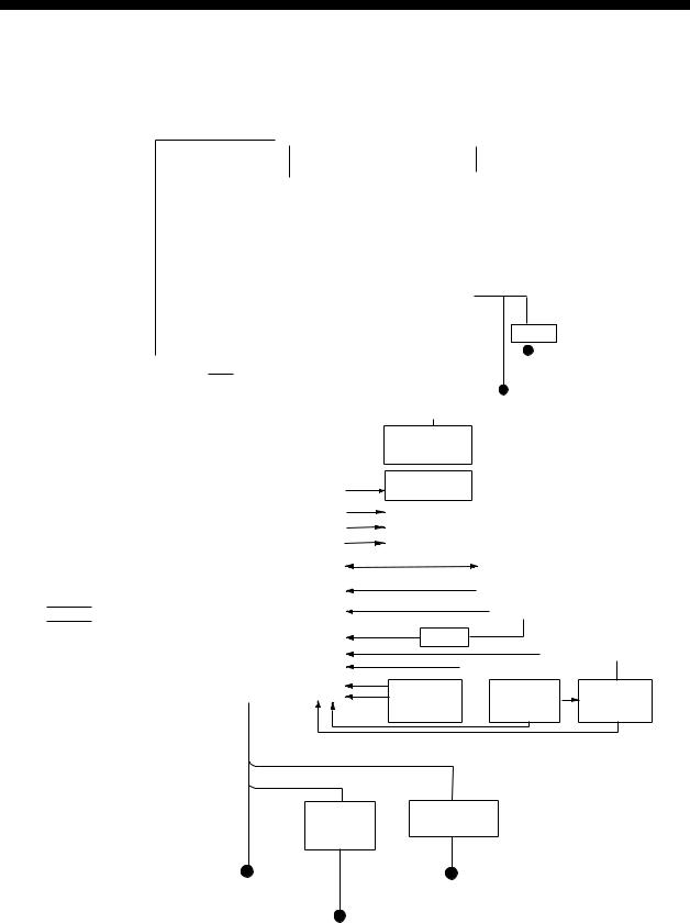
SYSTEM CONFIGURATION
With FURUNO-supplied monitor
|
FAR-2137S/2837S/2837SW |
FAR-2117/2127/2817/2827/2827W |
||||||||||||||||||||||||
|
ANTENNA UNIT |
ANTENNA UNIT |
||||||||||||||||||||||||
|
(Performance Monitor PM-51 built in) |
(Performance Monitor PM-31 built in) |
||||||||||||||||||||||||
|
Waveguide or |
Waveguide |
||||||||||||||||||||||||
|
(For FAR-2827W) |
|||||||||||||||||||||||||
|
Coax cable |
|||||||||||||||||||||||||
|
(For FAR-2837SW) |
|||||||||||||||||||||||||
|
TRANSCEIVER UNIT |
TRANSCEIVER UNIT |
||||||||||||||||||||||||
|
RTR-081 |
|||||||||||||||||||||||||
|
RTR-082 |
|||||||||||||||||||||||||
|
For FAR-2827W |
|||||||||||||||||||||||||
|
For FAR-2837SW |
|||||||||||||||||||||||||
|
MONITOR UNIT |
|||||||||||||||||||||||||
|
MU-201CR |
|||||||||||||||||||||||||
|
(FAR-21×7) |
|||||||||||||||||||||||||
|
or |
|||||||||||||||||||||||||
|
MU-231CR |
24 VDC |
||||||||||||||||||||||||
|
(FAR-28×7) |
RU-3423 |
||||||||||||||||||||||||
|
CONTROL UNIT |
115/230 VAC |
||||||||||||||||||||||||
|
POWER SUPPLY UNIT |
RCU-014 |
||||||||||||||||||||||||
|
PSU-007 |
(Keyboard) |
||||||||||||||||||||||||
|
For FAR-2137S/2837S |
or |
||||||||||||||||||||||||
|
For power for |
RCU-015 |
24 VDC |
|||||||||||||||||||||||
|
(Trackball) |
|||||||||||||||||||||||||
|
or |
|||||||||||||||||||||||||
|
antenna unit |
|||||||||||||||||||||||||
|
see next page. |
Control Unit |
115/230 VAC |
|||||||||||||||||||||||
|
RCU-016 |
|||||||||||||||||||||||||
|
(Remote) |
|||||||||||||||||||||||||
|
PROCESSOR UNIT |
|||||||||||||||||||||||||
|
RPU-013 |
Sub Display |
||||||||||||||||||||||||
|
Alarm |
|||||||||||||||||||||||||
|
VDR |
|||||||||||||||||||||||||
|
External Monitor |
|||||||||||||||||||||||||
|
IEC-61162-1 Serial Data |
Navigator (INS, GPS, etc.) |
||||||||||||||||||||||||
|
(Input/Output) |
|||||||||||||||||||||||||
|
: Standard |
IEC-61162-1 Serial Data |
Speed Log |
|||||||||||||||||||||||
|
(Input) |
|||||||||||||||||||||||||
|
: Option |
|||||||||||||||||||||||||
|
Gyrocompass |
|||||||||||||||||||||||||
|
: Dockyard supply |
|||||||||||||||||||||||||
|
AD-100 |
|||||||||||||||||||||||||
|
Category of Units |
AIS |
100-230 VAC |
|||||||||||||||||||||||
|
Antenna unit: Exposed to weather |
Track Control Unit |
||||||||||||||||||||||||
|
All other units: Protected from weather |
|||||||||||||||||||||||||
|
Memory Card OR Memory Card |
|||||||||||||||||||||||||
|
Switching Hub |
|||||||||||||||||||||||||
|
Interface Unit |
Interface Unit |
||||||||||||||||||||||||
|
HUB-100 |
|||||||||||||||||||||||||
|
CU-200 |
CU-200 x 2 |
||||||||||||||||||||||||
|
HUB has ports for connection of up to 7 processor units |
|||||||||||||||||||||||||
|
AC spec |
|||||||||||||||||||||||||
|
DC spec |
|||||||||||||||||||||||||
|
Rectifier |
Transformer Unit |
||||||||||||||||||||||||
|
RU-3424 |
RU-1803 |
||||||||||||||||||||||||
|
RU-1746B-2 |
|||||||||||||||||||||||||
|
24 VDC |
440 VAC |
||||||||||||||||||||||||
|
or |
1φ, 50-60 Hz |
||||||||||||||||||||||||
|
100-115 VAC/ |
|||||||||||||||||||||||||
|
220-230 VAC |
|||||||||||||||||||||||||
|
1φ, 50-60 Hz |
100/110/115/ |
220/230 VAC
1φ, 50-60 Hz
xiv
SYSTEM CONFIGURATION
Antenna unit
|
FAR-2117, |
RSB-096 (24 rpm) |
|
FAR-2117-BB |
RSB-097 (42 rpm) |
|
FAR-2127, |
|
|
FAR-2127-BB, |
|
|
FAR-2827, |
|
|
FAR-2137S, |
RSB-098/099 (21/26 rpm, 200 VAC, 3ø, 50 Hz; 220 VAC, 3ø, 60 Hz; 380 |
|
FAR-2137S-BB |
VAC, 3ø, 50 Hz, 440 VAC, 3ø, 60 Hz) |
|
RSB-100/101/102 (45 rpm, 220 VAC, 3ø, 50/60 Hz(HSC); |
|
|
440 VAC, 3ø, /60 Hz(HSC)) |
|
|
FAR-2827W |
RSB-103 (24 rpm, powered by processor unit) |
|
FAR-2837S |
Same as FAR-2137S |
|
FAR-2837SW |
RSB-104/105 (21/26 rpm, 200 VAC, 3ø, 50 Hz; 220 VAC, 3ø, 60 Hz; 380 |
|
VAC, 3ø, 50 Hz, 440 VAC, 3ø, 60 Hz) |
Radiator
|
FAR-2117, FAR-2117-BB |
XN12AF (4 ft), XN20AF (6.5 ft), |
|
FAR-2127, FAR-2127-BB, |
XN24AF (8 ft) |
|
FAR-2827 |
|
|
FAR-2137S, FAR-2137S-BB |
SN30AF (10 ft), SN36AF (12 ft) |
|
FAR-2827W |
XN20AF (6.5 ft), XN24AF (8 ft) |
|
FAR-2837S |
SN30AF (10 ft), SN36AF (12 ft) |
|
FAR-2837SW |
SN30AF (10 ft), SN36AF (12 ft) |
xv
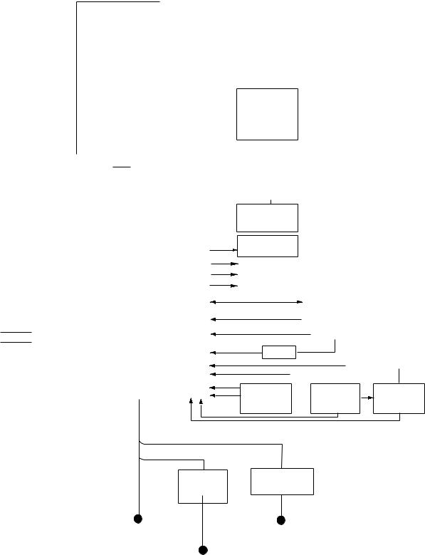
SYSTEM CONFIGURATION
Blackbox type
|
FAR-2137S-BB |
FAR-2117-BB/2127-BB |
||||||||||||||||||
|
ANTENNA UNIT |
ANTENNA UNIT |
||||||||||||||||||
|
(Performance Monitor PM-51 built in) |
(Performance Monitor PM-31 built in) |
||||||||||||||||||
|
VGA |
||||||||||||
|
MONITOR |
||||||||||||
|
CONTROL UNIT |
||||||||||||
|
POWER SUPPLY UNIT |
RCU-014 |
|||||||||||
|
PSU-007 |
(Keyboard) |
|||||||||||
|
For FAR-2137S-BB |
or |
|||||||||||
|
RCU-015 |
||||||||||||
|
(Trackball) |
||||||||||||
|
Control Unit |
||||||||||||
|
RCU-016 |
||||||||||||
|
(Remote) |
||||||||||||
|
PROCESSOR UNIT |
||||||||||||
|
RPU-013 |
Sub Display |
|||||||||||
|
Alarm |
||||||||||||
|
VDR |
||||||||||||
|
External Monitor |
||||||||||||
|
IEC-61162-1 Serial Data |
Navigator (INS, GPS, etc.) |
|||||||||||
|
(Input/Output) |
||||||||||||
|
: Standard |
IEC-61162-1 Serial Data Speed Log |
|||||||||||
|
(Input) |
||||||||||||
|
: Option |
Gyrocompass |
|||||||||||
|
: Dockyard supply |
||||||||||||
|
AD-100 |
||||||||||||
|
Category of Units |
AIS |
100-230 VAC |
||||||||||
|
Antenna unit: Exposed to weather |
Track Control Unit |
|||||||||||
|
All other units: Protected from weather |
Memory Card OR |
Memory Card |
||||||||||
|
Switching Hub |
||||||||||||
|
Interface Unit |
Interface Unit |
|||||||||||
|
HUB-100 |
||||||||||||
|
CU-200 |
CU-200 x 2 |
|||||||||||
|
HUB has ports for connection of up to 7 processor units |
||||||||||||
|
AC spec |
||||||||||||
|
DC spec |
||||||||||||
|
Rectifier |
Transformer Unit |
|||||||||||
|
RU-3424 |
RU-1803 |
|||||||||||
|
RU-1746B-2 |
||||||||||||
|
24 VDC |
440 VAC |
|||||||||||
|
or |
1φ, 50-60 Hz |
100-115 VAC/
220-230 VAC
1φ, 50-60 Hz 100/110/115/ 220/230 VAC 1φ, 50-60 Hz
xvi
|
SYSTEM CONFIGURATION |
||||||||||||||||||||
|
Console type RCN-001/RCN-002 |
||||||||||||||||||||
|
FAR-2137S/2837S/2837SW |
FAR-2117/2127/2817/2827/2827W |
|||||||||||||||||||
|
ANTENNA UNIT |
ANTENNA UNIT |
|||||||||||||||||||
|
(Performance Monitor PM-51 built in) |
(Performance Monitor PM-31 built in) |
|||||||||||||||||||
|
Waveguide or |
Waveguide |
|||||||||||||||||||
|
(For FAR-2827W) |
||||||||||||||||||||
|
Coax cable |
||||||||||||||||||||
|
(For FAR-2837SW) |
||||||||||||||||||||
|
TRANSCEIVER UNIT |
TRANSCEIVER UNIT |
|||||||||||||||||||
|
RTR-081 |
||||||||||||||||||||
|
RTR-082 |
||||||||||||||||||||
|
For FAR-2827W |
||||||||||||||||||||
|
For FAR-2837SW |
||||||||||||||||||||
CONSOLE
RCN-001/002
POWER SUPPLY UNIT
PSU-007
For FAR-2137S/2837S
|
PROCESSOR |
||||
|
UNIT |
||||
|
RPU-013 |
||||
|
: Standard |
||||
|
OR |
||||
|
: Option |
||||
|
: Dockyard supply |
May also |
|||
|
be installed |
||||
|
Category of Units |
externally. |
|||
|
Antenna unit: Exposed to weather |
Memory Card |
|||
|
All other units: Protected from weather |
Interface Unit |
|||
|
CU-200 |
 Alarm
Alarm
 VDR
VDR
 External Monitor
IEC-61162-1 Serial Data
|
(Input/Output) |
Navigator (INS, GPS, etc.) |
IEC-61162-1 Serial Data Speed Log
(Input)
Gyrocompass
AD-100
AIS
Track Control Unit
100-230 VAC
Memory Card
Interface Unit
|
Switching Hub |
CU-200 |
|
|
HUB-100 |
||
|
(Max. 2 total) |
||
AC spec
Transformer Unit
RU-1803
|
100-115 VAC/ |
440 VAC |
|
220-230 VAC |
1φ, 50-60 Hz |
|
1φ, 50-60 Hz |
xvii

SYSTEM CONFIGURATION
Console type RCN-003/RCN-004
|
FAR-2137S/2837S/2837SW |
FAR-2117/2127/2817/2827/2827W |
|||||||||||||||||||
|
ANTENNA UNIT |
ANTENNA UNIT |
|||||||||||||||||||
|
(Performance Monitor PM-51 built in) |
(Performance Monitor PM-31 built in) |
|||||||||||||||||||
|
Waveguide or |
Waveguide |
|||||||||||||||||||
|
(For FAR-2827W) |
||||||||||||||||||||
|
Coax cable |
||||||||||||||||||||
|
(For FAR-2837SW) |
||||||||||||||||||||
|
TRANSCEIVER UNIT |
TRANSCEIVER UNIT |
|||||||||||||||||||
|
RTR-081 |
||||||||||||||||||||
|
RTR-082 |
||||||||||||||||||||
|
For FAR-2827W |
||||||||||||||||||||
|
For FAR-2837SW |
||||||||||||||||||||
|
CONSOLE |
Alarm |
||||||||
|
RCN-003/004 |
|||||||||
|
POWER SUPPLY UNIT |
|||||||||
|
PSU-007 |
VDR |
||||||||
|
For FAR-2137S/2837S |
|||||||||
|
External Monitor |
|||||||||
|
IEC-61162-1 Serial Data |
Navigator (INS, GPS, etc.) |
||||||||
|
(Input/Output) |
|||||||||
|
IEC-61162-1 Serial Data |
Speed Log |
||||||||
|
(Input) |
|||||||||
|
Gyrocompass |
|||||||||
|
PROCESSOR |
|||||||||
|
UNIT |
AD-100 |
||||||||
|
RPU-013 |
|||||||||
|
: Standard |
AIS |
||||||||
|
Switching Hub |
|||||||||
|
: Option |
Track Control Unit |
||||||||
|
HUB-100 |
|||||||||
|
: Dockyard supply |
|||||||||
|
Category of Units |
Memory Card |
||||||||
|
Antenna unit: Exposed to weather |
Memory Card |
||||||||
|
All other units: Protected from weather |
Interface Unit |
Interface Unit |
|||||||
|
CU-200 |
CU-200 |
||||||||
|
(Max. 2 total) |
AC spec
Transformer Unit
RU-1803
|
100-115 VAC/ |
440 VAC |
|
220-230 VAC |
1φ , 50-60 Hz |
|
1φ , 50-60 Hz |
xviii
![]()
FURUNO
FAR-21×7(-BB)/28×7 SERIES
SPECIFICATIONS OF MARINE RADAR/ARPA
FAR-21×7(-BB)/28×7 SERIES
1. ANTENNA RADIATORS
|
1. |
Type |
Slotted waveguide array |
||||||||
|
2. |
Beam width and sidelobe attenuation |
|||||||||
|
S-band |
||||||||||
|
Radiator type |
X-band |
|||||||||
|
XN12AF |
XN20AF |
XN24AF |
SN30AF |
SN36AF |
||||||
|
Length |
4 ft |
6.5 ft |
8 ft |
10 ft |
12 ft |
|||||
|
Beam width(H) |
1.8° |
1.23° |
0.95° |
2.3° |
1.8° |
|||||
|
Beam width(V) |
20° |
20° |
20° |
25° |
25° |
|||||
|
Sidelobe within ±10° |
-24 db |
-28db |
-28 db |
-24 db |
-24 db |
|||||
|
Sidelobe outside ±10° |
-30 db |
-32 db |
-32 db |
-30 db |
-30 db |
|||||
|
3. |
Polarization |
Horizontal |
||||||||
|
4. |
Rotation |
FAR-2117/2127/2827: 24 rpm or 42 rpm |
||||||||
|
FAR-2137S/2837S: 21/26 rpm or 45 rpm |
||||||||||
|
FAR-2827W: 24 rpm |
||||||||||
|
FAR-2837SW: 21/26 rpm |
2. RF TRANSCEIVER
|
1. |
Frequency |
X-band: 9410 MHz ±30 MHz, S-band: 3050 MHz ±30 MHz |
|||||||
|
2. |
Output power |
FAR-2117/2817: 12 kW |
FAR-2127/2827/2827W: 25 kW |
||||||
|
FAR-2137S/2837S/2837SW: 30 kW |
|||||||||
|
Unwanted emissions comply with ITU-R RR. |
|||||||||
|
3. |
Pulselength, PL, PRF and range |
||||||||
|
Pulselength |
S1 |
S2 |
M1 |
M2 |
M3 |
L |
|||
|
PL (µs) |
0.07 |
0.15 |
0.3 |
0.5 |
0.7 |
1.2 |
|||
|
PRF (Hz) |
3000* |
3000* |
1500 |
1000 |
1000 |
600** |
|||
|
Range scale |
0.125, |
0.5, 0.75, |
0.75, 1.5, |
3, 6, 12, |
3, 6, 12, |
6, 12, 24, |
|||
|
(nm) |
0.25, 0.5, |
1.5, 3 |
3, 6 |
24 |
24 |
48, 96, |
|||
|
*: |
0.75, 1.5 |
120# |
|||||||
|
2200 Hz with ARPA |
on, 32 nm range **: 450 Hz on 96 and 120 nm ranges |
#: Non-IMO type only |
|||||||
|
4. |
IF |
60 MHz |
|||||||
|
5. |
Noise figure |
6 dB (typical) |
|||||||
|
6. |
Duplexer |
Ferrite circulator with diode limiter for |
|||||||
|
FAR-2117/2127/2137S/2817/2827/2837S |
|||||||||
|
Ferrite circulator with TR limiter for FAR-2827W/2837SW |
3. DISPLAY UNIT
|
1. Screen |
Yellow or green echoes in 32 levels. Rasterscan non-interlace at |
||
|
48.3kHz horizontal, 60 Hz vertical. Non-IMO type has yellow or |
|||
|
green monochrome plus 3-color display according to echo strengths. |
|||
|
FAR-21×7 series |
FAR-28×7 series |
||
|
Size, model |
20.1-inch color LCD, MU-201CR |
23.1-inch color LCD, MU-231CR |
|
|
Display area (mm) |
399.36 x 319.49 |
470.4 x 352.8 |
|
|
Resolution |
1280 x 1024 pixels |
1280 x 1024 pixels |
|
|
Effective radar diameter |
308 mm |
340 mm |
|
|
2. Minimum range and |
|||
|
range discrimination |
35 m |
||
|
SP — 1 |
E3519S01C-M |
|
FURUNO |
FAR-21×7(-BB)/28×7 SERIES |
|||||||||||
|
3. |
Range scales (nm), |
0.125 (.025), 0.25 (0.05), 0.5 (0.1), 0.75 (0.25), 1 (0.25)*, 1.5 (0.25), |
||||||||||
|
ring interval |
3 (0.5), 4 (1)*, 6 (1), 8 (2)*, 12 (2), 16 (4)*, 24 (4), 32 (8)*, 48 (8), 96 |
|||||||||||
|
(16), 120 (20)* |
*: Non-IMO type only |
|||||||||||
|
4. |
Range accuracy |
1% of the maximum range of the scale in use or 30 m, whichever is |
||||||||||
|
the greater |
||||||||||||
|
5. |
Bearing discrimination |
Better than 2.5° |
||||||||||
|
6. |
Bearing accuracy |
±1° |
||||||||||
|
7. |
Presentation mode |
Head-up, Head-up TB, North-up, Course-up, True Motion sea or |
||||||||||
|
ground stabilization |
||||||||||||
|
8. |
Plotting facilities |
Auto or Manual acquisition: 100 targets in 0.1-32 nm |
||||||||||
|
(ARPA or ATA) |
Auto tracking on all acquired targets |
|||||||||||
|
9. |
Radar map |
Nav lines, coastlines, buoys, etc. produced by operator. 3000 pts in |
||||||||||
|
radar mode, 6000 pts on IC card in chart mode |
||||||||||||
|
10. Guard zone |
Two GZ anywhere |
|||||||||||
|
11. Parallel index line |
Choice of 2, 4 or 6 lines |
|||||||||||
|
12. AIS |
IMO SN Circ.217, IEC 60936-5 |
|||||||||||
|
13. Chart cards |
FURUNO and NAVIONICS |
|||||||||||
|
4. INTERFACE |
||||||||||||
|
1. |
IEC 61162-1 Ed. 2 |
RSD, TTM, AIS related data, etc. |
||||||||||
|
2. |
Compass |
Built-in interface (option) for sync signal (20-135 V, 50-400 Hz), or |
||||||||||
|
stepper signal (20-135 VDC), any polarity, for gyrocompass, GPS |
||||||||||||
|
compass SC-60/120 by IEC 61162-2 |
||||||||||||
|
3. |
Speed log |
NMEA format data |
||||||||||
|
4. |
Others |
Echo sounder, GPS navigator, water temperature, etc. |
||||||||||
|
5. POWER SUPPLY |
||||||||||||
|
1. |
Display unit |
24 VDC or 115/230 VAC, 1ø, 50/60 Hz |
||||||||||
|
FAR-21×7: 24 VDC, 2.3 A; 100-230 VAC, 0.7A (100 V) |
||||||||||||
|
FAR-28×7: 24 VDC, 3.2 A; 100-230 VAC, 0.9 A (100 V) |
||||||||||||
|
440 VAC, 1 ø, 50/60 Hz with optional transformer RU-1803 |
||||||||||||
|
2. Processor unit |
FAR-2117/2817/2117-BB: |
|||||||||||
|
24VDC: 7.6A1/8.5A2, 100-115 VAC: 2.6A1/3.0A2, |
||||||||||||
|
220-230 VAC: 1.6A1/1.7A2 |
||||||||||||
|
FAR-2127/2827/2127-BB: |
||||||||||||
|
24 VDC: 8.8A1/9.7A2, 100-115 VAC: 3.0A1/3.4A2, |
||||||||||||
|
220-230 VAC: 1.8A1/1.9A2 |
||||||||||||
|
1: 24 rpm, 2: 42 rpm |
||||||||||||
|
3. Antenna unit (S-band) |
200/220/380/440 VAC 115/230 VAC, 1ø, 50 or 60 Hz |
|||||||||||
|
Antenna voltage input (100 kt) |
||||||||||||
|
200 VAC, |
380 VAC, |
220 VAC, |
220 VAC, |
220 VAC, |
||||||||
|
ø3, 50 Hz, |
ø3, 50 Hz, |
ø3, 50 Hz, |
ø3, 60 Hz |
ø3, 60 Hz |
||||||||
|
220 VAC, |
380 VAC, |
(HSC) |
(HSC) |
(HSC) |
||||||||
|
ø3, 60 Hz |
ø3, 60 Hz |
|||||||||||
|
FAR-2137S |
3.0 A |
1.5 A |
3.5 A |
3.5 A |
1.7 A |
|||||||
|
FAR-2837S |
3.0 A |
1.5 A |
3.5 A |
3.5 A |
1.7 A |
|||||||
|
FAR-2837SW |
3.0 A |
1.5 A |
— |
— |
— |
|||||||
|
FAR-2137SW |
3.0 A |
1.5 A |
3.5 A |
3.5 A |
1.7A |
|||||||
|
SP — 2 |
E3519S01C-M |
|
FURUNO |
FAR-21×7(-BB)/28×7 SERIES |
|
4. Console |
115/230 VAC, 1ø, 50/60 Hz, 440 VAC, 1ø, 50/60 Hz with optional |
|
transformer RU-1803 |
6. ENVIRONMENTAL CONDITIONS
|
1. |
Ambient temperature (Complies with IEC 60945) |
|
|
Indoor units |
-15°C to +55°C |
|
|
Antenna unit |
-25°C to +55°C (storage +70°C) |
|
|
2. |
Relative humidity |
95% at 40°C |
|
3. |
Waterproofing |
Antenna unit: IPX6 (IEC 60529) |
|
Indoor units: IPX0 (IEC 60529) |
||
|
4. |
EMC |
Full compliance with IEC 60945 Ed. 4 |
|
(to 2 GHz cabinet radiation) |
7. OPTIONAL EQUIPMENT
|
SWITCHING HUB HUB-100 |
||
|
1. Access Format |
CSMA/CD |
|
|
2. |
Switching Format |
Store and Forward |
|
3. |
Transmission Speed |
Half-duplex: 10Mbps/100Mbps |
|
Full-duplex: 20Mbps/200Mbps |
||
|
4. |
Necessary Cabling |
10BASE-T: Category 3 or higher STP cable |
|
100 BASE-TX: Category 5 or higher STP cable |
||
|
5. |
Max. Cable Length |
100 m |
|
6. |
Ports |
8 ports |
|
— All ports auto-MDIX compliant (straight or cross cable, |
||
|
automatic recognition) |
||
|
— All ports EMC compliant (STP cable port) |
||
|
— All ports equipped with 3 LED injectors |
||
|
(Link/Act, Full-duplex/Collision, 100Mbps/10Mbps) |
||
|
7. |
Buffer Memory |
SRAM buffer |
|
8. |
MAC Address Table |
1024 |
|
9. |
Dimensions and Mass |
|
|
Dimensions |
47(H)x270(W)x1458(D) (mm) includes fixing screws |
|
|
Mass |
Less than 1.6 kg |
|
|
10. Environmental Conditions |
||
|
Ambient Temperature -15 to +55°C |
||
|
Relative Humidity |
95% (at 40°C) |
|
|
EMC |
IEC 60945 |
|
|
Waterproofing |
IPX0 (IEC 60529) |
|
|
11.Power and Power Consumption |
||
|
Power |
100-230 VAC |
|
|
Power Consumption |
100mA/100 VAC |
|
|
12. Coating and Color |
N3.0 |
SP — 3
E3519S01D-M 8/17/2004
FURUNO
FAR-21×7(-BB)/28×7 SERIES
Precautions for high speed targets
Assume your ship is making 40 kt and a target ship is approaching at 49 kt right toward you. Then the relative speed is 80 kt. With the antenna rotating at 42 rpm, the target blip appears jumping to a new location 59 m nearer. This jump corresponds to 19 mm on the display using the 0.25 nm range scale. On such a short range you may lose the track of a target in the midst of sea clutter, random noise or other targets. Use one step larger range scale.
ARPA can fail to track a target when the relative speed exceeds 100 kt.

1 RADAR OPERATION
1.1Turning on the Power
The [POWER] switch is located at the left corner of the control unit. Open the power switch cover and press the switch to turn on the radar system. To turn off the radar, press the switch again. The screen shows the bearing scale and digital timer approximately 30 seconds after power-on. The timer counts down three minutes of warm-up time. During this period the magnetron (transmitter tube) is warmed for transmission. When the timer has reached 0:00, the indication “ST-BY” appears at the screen center, meaning the radar is now ready to transmit pulses.
In the stand-by condition, markers, rings, map, charts, etc. are not shown. Further, ARP is cancelled and the AIS display is erased.
In warm-up and stand-by condition, ON TIME and TX TIME counts in hours and tenths of hour appear at the screen center.
1.2Transmitter ON
After the power is turned on and the magnetron has warmed up, ST-BY appears at the screen center, meaning the radar is ready to transmit radar pulses. You may transmit by pressing the [STBY/TX] key on the full keyboard or roll the trackball to choose the TX STBY box at the bottom left corner of the display and then push the left button (above the trackball). The label at the left-hand side of the guidance box at the bottom right corner of the screen changes from TX to STBY.
|
TX |
STBY / |
|||
|
STBY |
Guidance |
|||
|
box |
||||
|
TX STBY box |
Radar display
1-1
1. RADAR OPERATION
The radar is initially set to previously used range and pulse length. Other settings such as brilliance levels, VRMs, EBLs and menu option selections are also set to previous settings.
The [STBY/TX] key (or TX STBY box) toggles the radar between STBY and TRANSMIT status. The antenna stops in stand-by and rotates in transmit. The magnetron ages with time resulting in a reduction of output power. Therefore, it is highly recommended that the radar be set to stand-by when not used for an extended period of time.
Quick start
Provided that the radar was once in use with the transmitter tube (magnetron) still warm, you can turn the radar into TRANSMIT condition without three minutes of warm-up. If the [POWER] switch has been turned off by mistake or the like and you wish to restart the radar promptly, turn on the [POWER] switch not later than 10 seconds after power-off.
1-2
1. RADAR OPERATION
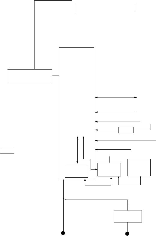
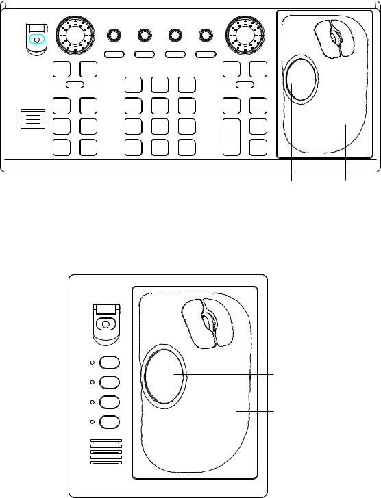
1.3Control Unit
Two types of control units are available: Control Unit RCU-014 (full keyboard) and Control Unit RCU-105 (palm control).
|
EBL rotary control |
VRM rotary control |
Wheel |
||||||||
|
Left button |
Right button |
|||||||||
|
BRILL |
A/C RAIN |
A/C SEA |
GAIN |
||
|
OFF |
ON |
||||
|
1 |
2 |
3 |
|||
|
EBL |
HL |
EBL |
MODE |
||
|
OFF |
OFFSET |
||||
|
4 |
5 |
6 |
|||
|
F1 |
F2 |
OFF |
CU/TM |
INDEX |
|
|
CENTER |
RESET |
LINE |
|||
|
7 |
8 |
9 |
|||
|
F3 |
F4 |
VECTOR |
VECTOR |
TARGET |
|
|
TIME |
MODE |
LIST |
|||
|
ALARM |
STBY |
CANCEL |
0 |
ENTER |
|
|
ACK |
TX |
TRAILS |
BRILL |
MARK |
ON
VRM
ACQ
TARGET
DATA
TARGET
CANCEL
Trackball Trackball
Module
Control Unit RCU-014 (full keyboard)
Wheel
|
Left button |
Right button |
||||
F1
|
F2 |
Trackball |
|
F3 |
Trackball |
|
F4 |
Module |
Control Unit RCU-015 (palm control)
1-3
1. RADAR OPERATION
|
Control description |
|
|
Control |
Description |
|
Control Unit RCU-014 (full keyboard) |
|
|
POWER |
Turns the system on and off. |
|
EBL and VRM rotary controls |
Adjust EBL and VRM, respectively. |
|
EBL ON, EBL OFF |
Turns the EBLs on and off, respectively. |
|
F1-F4 |
Execute menu short cut assigned. |
|
ALARM ACK |
Silences audible alarm. |
|
STBY TX |
Toggles between stand-by and transmit. |
|
BRILL |
Adjusts display brilliance. |
|
A/C RAIN |
Suppresses rain clutter. |
|
A/C SEA |
Suppresses sea clutter. |
|
GAIN |
Adjusts sensitivity of the radar receiver. |
|
HL OFF |
Temporarily erases the heading line while pressed. |
|
EBL OFFSET |
Enables, disables the EBL offset. In menu operation, switches |
|
polarity from North to South and East to West and vice versa. |
|
|
MODE |
Chooses presentation mode. |
|
OFF CENTER |
Shifts own ship position. |
|
CU/TM RESET |
• Moves own ship position in 75% radius in stern direction. |
|
• Resets the heading line to 0° in course-up and true motion |
|
|
modes. |
|
|
INDEX LINE |
Turns index lines on and off. |
|
VECTOR TIME |
Chooses vector time (length). |
|
VECTOR MODE |
Chooses vector mode, relative or true. |
|
TARGET LIST |
Displays ARP target list. |
|
CANCEL TRAILS |
Cancels all target trails. In menu operation it clears line of data. |
|
ENTER MARK |
Enters marks; terminates keyboard input. |
|
VRM ON, VRM OFF |
Turns the VRMs on and off, respectively |
|
MENU |
Opens and closes the MAIN menu; closes other menus. |
|
ACQ |
• Acquires a target for ARP after choosing it with the trackball. |
|
• Changes a sleeping AIS target to an activated one after |
|
|
choosing it with the trackball. |
|
|
RANGE |
Chooses radar range. |
|
TARGET DATA |
Displays target data for ARP or AIS target chosen with the |
|
trackball. |
|
|
TARGET CANCEL |
Cancels tracking on ARP, AIS or reference target chosen with |
|
the trackball. |
|
|
Control Unit RCU-015 (palm control) |
|
|
POWER |
Turns the system on and off. |
|
F1-F4 |
Execute menu short cut assigned. |
1-4

1. RADAR OPERATION
1.4Main Menu
You may access the MAIN menu from the full keyboard or by using the trackball. In later sections only the procedure for menu operation by trackball is given.
Main menu operation by keyboard
1.Press the [MENU] key. The MAIN menu appears in the text area at the right side of the screen.
|
[MAIN MENU] |
||||||||||
|
1 |
[ECHO] |
Echo processing functions |
||||||||
|
2 |
[MARK] |
Mainly turns markers on/off. |
||||||||
|
3 |
[ALARM] |
Sets guard alarm functions; outputs alarm signal. |
||||||||
|
4 |
[ARPl AIS] |
Sets ARP and AIS functions. |
||||||||
|
5 |
[PLOTTER] |
Chart and track functions |
||||||||
|
6 |
[CARD] |
Memory card functions |
||||||||
|
7 |
[NAV DATA] |
Turns nav data on/off. |
||||||||
|
8 |
[NAV LINE l WPT] |
Processes nav lines and waypoints. |
||||||||
|
9 |
[CUSTOMIZE l TEST] |
Customizes operation; executes diagnostics. |
||||||||
MAIN menu
2.Press the numeral key corresponding to the menu you wish to open. For example, press the [2] key to open MARK menu.
[MARK]
1BACK
2OWN SHIP MARK OFF/ON
3STERN MARK OFF/ON
4INDEX LINE BEARING REL/TRUE
5INDEX LINE 1/2/3/6
6INDEX LINE MODE VERTICAL/HORIZONTAL
8EBL OFFSET BASE STAB GND/STAB HDG/ STAB NORTH
9EBL CURSOR BEARING REL/TRUE
|
3. |
Press the numeral key corresponding to the |
Useful keys in menu operation |
|
item you wish to set. |
||
|
4. |
Consecutively press the same numeral key |
l |
|
pressed at step 3 to choose appropriate |
To clear a line of numeric data: |
|
|
Use the [CANCEL TRAILS] key. |
||
|
option and then press the [ENTER MARK] |
l Switch between plus and minus, |
|
|
North and South or East and West: |
||
|
key to register your selection. |
||
|
5. |
Use the [2] key. |
|
|
Press the [MENU] key to close the menu. |
1-5

1. RADAR OPERATION
Main menu operation by trackball
1.Roll the trackball to choose the MENU box at the right side of the screen. The guidance box at the bottom right corner (see the illustration at the bottom of the next page for location) now reads “DISP MAIN MENU.”
MENU
|
Menu box |
|||||||||||
|
2. Push the left button to display the MAIN menu. |
|||||||||||
|
[MAIN MENU] |
|||||||||||
|
1 |
[ECHO] |
Echo processing functions |
|||||||||
|
2 |
[MARK] |
Mainly turns markers on/off. |
|||||||||
|
3 |
[ALARM] |
Sets guard alarm functions; outputs alarm signal. |
|||||||||
|
4 |
[ARPl AIS] |
Sets ARP and AIS functions. |
|||||||||
|
5 |
[PLOTTER] |
Chart and track functions |
|||||||||
|
6 |
[CARD] |
Memory card functions |
|||||||||
|
7 |
[NAV DATA] |
Turns nav data on/off. |
|||||||||
|
8 |
[NAV LINE l WPT] |
Processes nav lines and waypoints. |
|||||||||
|
9 |
[CUSTOMIZE l TEST] |
Customizes operation; executes diagnostics. |
|||||||||
MAIN menu
3.Roll the wheel to choose the menu you wish to open and then push the wheel or the left button. For example, choose the 2 [MARK] menu and then push the wheel or the left button.
[MARK]
1BACK
2OWN SHIP MARK OFF/ON
3STERN MARK OFF/ON
4INDEX LINE BEARING REL/TRUE
5INDEX LINE 1/2/3/6
6INDEX LINE MODE VERTICAL/HORIZONTAL
8EBL OFFSET BASE STAB GND/STAB HDG/ STAB NORTH
9EBL CURSOR BEARING
REL/TRUE
0RING OFF/ON
MARK menu
4.Roll the wheel to choose item desired and then push the wheel or the left button.
5.Roll the wheel to choose option desired and then push the wheel or the left button to register your selection.
6.Push the right button to close the menu. (Several pushes may be necessary depending on the menu used.)
1-6
![]()
1. RADAR OPERATION
1.5Operation Using the On-Screen Boxes
All radar functions can be accessed by using the trackball alone. This is done by choosing the appropriate on-screen box with the trackball and operating the trackball module to choose item and option. (See paragraph 1.9 for location of all on-screen boxes.) On-screen boxes come in two varieties: Function selection and function selection w/pop-up menu. On-screen boxes of the latter type have “►” at the right side of their boxes, as in the MARK box shown below.
To operate the radar using on-screen boxes, do the following:
1.Roll the trackball to place the trackball marker inside the box desired.
Note: The trackball marker changes its configuration according to its location. It is an arrow when placed outside the effective display and a cursor
(+)when inside the effective display. See the illustration on the next page for further details.
For example, choose the MARK box, which is at the bottom left corner.
|
MARK 4 |
|||||
|
Mark type last |
|||||
|
1 |
-> + |
||||
|
selected, mark |
|||||
|
number |
162.5°T 11.7 NM |
Bearing and range from own ship to origin mark
MARK box
When a box is correctly selected, its color changes from green to yellow (default colors) and the guidance box at the bottom right corner shows operational guidance. The operational guidance shows the function of the left and right buttons, with a diagonal line separating the information. For the MARK box, for example, the operational guidance is “MARK SELECT / MARK MENU.” In this case you would push the left button to choose a mark or push the right button to open the MARK menu.
Function of left button
Function of right button
|
MARK 4 |
||||||||
|
MARK Box |
||||||||
|
1 |
> |
+ |
MENU Guidance box |
|||||
|
SELECT / |
||||||||
|
MARK |
MARK |
Arrow
For choosing on-screen box
Guidance box (Example: guidance for MARK box)
1-7

1. RADAR OPERATION
Trackball marker location and guidance box indication
The trackball marker is either a cursor (+) or an arrow ( ) depending on whether it is within or outside the display area, respectively. Further, the indication in the guidance box changes according to trackball marker location.
Trackball marker is out of effective display area (incl. text area) and
not selecting a box: The trackball marker is an arrow
+
Trackball marker is within effective display area: The trackball marker is
Guidance box reads
«JUMP CURSOR / DISP MENU.»
Push the left button to choose the on-screen box closest to the arrow or push the right button to display the MAIN menu.
To choose boxes successively, push the wheel when the guidance box reads as above. Then, the nearest box is selected and marked with the double-ended arrow ( ) and the guidance box reads
«JUMP FORWARD / JUMP BACKWARD.» Hit the left button to go to the box below or adjacent to the currently selected box or hit the right button to go to the box above or adjacent to the currently selected box. Continue pushing a button to choose boxes successively. This is convenient for operation
under heavy pitching and rolling. To cancel this feature, push the wheel when the guidance box reads as above.
Guidance box reads
«TARGET DATA & ACQ / CURSOR MENU.»
In this condition you may access cursor-operated functions, by hitting the left button for direct selection of function or the right button to choose desired functions from the CURSOR menu. For further details about the CURSOR menu,
see paragraph 1.6.
acursor
2.Push the left button (or roll the wheel depending on the box) until the desired option is displayed in the box.
Note: When you chose an on-screen box’s option by rolling the wheel, the box and its contents turn red. This simply indicates that the chosen setting is different from the currently active setting. To change the setting, push the wheel or the left button. If neither the wheel nor the left button is pushed within about 30 seconds after operating the wheel, the previous setting is automatically restored.
1-8

1. RADAR OPERATION
3.The pop-up menu attached to the MARK box is the MARK menu. To open the menu, push the right button. The menu opens in the text area at the right side of the screen.
[MARK MENU]
1ORIGIN MARK STAB GND/SEA
2MARK KIND ORIGIN MARK(No.)/
ORIGIN MARK(SYM)/ MAP MARK/
WP 1~50/ WP 51~100/ WP 101~150/ WP 151~198/
OWN SHIP SHAPE
|
9 |
MAP DISPLAY |
||
|
OFF/ON |
* Not available |
||
|
0 |
MAP MARK COLOR* |
||
|
on IMO radar. |
|||
|
RED/GRN/BLU/YEL/ |
|||
|
CYA/MAG/WHT |
MARK menu
Note: Any menu may be operated from the full keyboard or the trackball, or a combination of the two in case of Control Unit RCU-014. Note that in later sections only the procedure for menu operation by the trackball is given.
4.Roll the wheel to choose item desired and then push the wheel or the left button. Selected item is initially shown in reverse video and changes to normal video and circumscribed when the wheel or the left button is pushed.
5.Roll the wheel to choose option desired and then push the wheel or the left button. Selected option is initially shown in reverse video and changes to normal video and circumscribed when the wheel or the left button is pushed.
6.Push the right button to close the menu. (On some menus several presses of the right button are required to close the menu.)
1-9

1. RADAR OPERATION
1.6Cursor Menu
Functions which require the use of the cursor, such as EBL offset and zoom, may be activated directly from the guidance box or from the CURSOR menu, either method with the cursor inside the effective display area. Below is the procedure for choosing a cursor-related function from the CURSOR menu. In later sections only the procedure for selection from the guidance box is given.
1.Roll the trackball to place the cursor inside the effective display area.
2.Roll the wheel to show “TARGET DATA & ACQ / CURSOR MENU” in the guidance box.
3.Push the right button to show the CURSOR menu.
[CURSOR MENU]
2 ↓
TARGET DATA & ACQ/ TARGET CANCEL/ ACQ/
REF MARK/ EBL OFFSET/ OFFCENTER ZOOM/
MARK DELETE/
CHART ALIGN 8 ↑
CURSOR menu
4.Roll the wheel to choose “2” and then push the wheel or the left button.
5.Roll the wheel to choose function desired and then push the wheel or the left button.
Note: For operation from the keyboard, you may press the [2] key to choose a function in top-to-bottom order or the [8] key to choose in reverse order.
|
Cursor Menu item |
Description |
|
TARGET DATA & ACQ |
ARP: Acquires ARP target; displays data for chosen ARP |
|
target. |
|
|
AIS: Activates sleeping AIS target; display data for chosen |
|
|
AIS target. |
|
|
TARGET CANCEL |
ARP: Cancels tracking on chosen ARP target. |
|
AIS: Sleeps chosen AIS target. |
|
|
ACQ |
ARP: Acquires chosen echo. |
|
AIS: Activates chosen AIS target. |
|
|
REF MARK |
Inscribes reference mark, for target-based speed input. |
|
EBL OFFSET |
Offsets EBL, to measure range and bearing between two |
|
targets. |
|
|
OFF CENTER |
Shifts screen center to chosen location. |
|
ZOOM |
Zooms chosen location. |
|
MARK DELETE |
Deletes chosen mark (plotter mark, origin mark or |
|
waypoint mark). |
|
|
CHART ALIGN |
Aligns chart with radar picture. |
1-10

1. RADAR OPERATION
6.The guidance box shows “XX / EXIT.” (XX = function chosen). Roll the trackball to place the cursor where desired.
7.Push the left button to execute the function selected at step 5.
8.To quit the function selected, push the right button when the guidance box shows “XX / EXIT.” (XX = function chosen at step 5)
1.7Monitor Brilliance
The brilliance of the entire screen should be adjusted according to lighting conditions. Monitor brilliance should be adjusted before adjusting relative brilliance levels on the BRILL menu to be explained later.
Note: The brilliance of a commercial monitor cannot be adjusted from the radar. See the owner’s manual of the commercial monitor for how to adjust its brilliance.
By keyboard
Operate the [BRILL] control on the control unit to adjust brilliance. Turn it clockwise to increase brilliance; counterclockwise to decrease brilliance. Watch the BRILL box (see illustration below) to know current brilliance level.
By trackball
1.Roll the trackball to place the arrow on the brilliance level indicator in the brilliance level indication box at the bottom left corner of the screen.
Brilliance bar
Shows brilliance level.
Place arrow inside box
to adjust screen brilliance.
BRILL1 4
 26
26
Brilliance level
Brillance, color set no.
(For details, see para. 1.50.)
Brilliance level indicator
2.Roll the wheel downward to increase brilliance or roll it upward to decrease brilliance. The length of the brilliance bar increases or decreases with operation of the wheel.
Note: If nothing appears on the screen at power-up when using Control Unit RCU-015 (palm control) or when the radar is in stand-by, press and hold down any key except the power switch for four seconds to automatically set up for medium display brilliance.
1-11

1. RADAR OPERATION
1.8Choosing the Display Mode
This radar has two display modes: Radar and Radar + Plotter. Choose a display mode as below. Note that a display mode cannot be chosen when the menu is open.
1.Roll the trackball to place the arrow in the DISPLAY MODE box at the top of the screen.
DISPLAY
XX* 4
* XX = display mode (RADAR, +PLOTTER)
DISPLAY MODE box
2.Push the left button to choose appropriate mode: RADAR: Radar picture
+PLOTTER: Radar picture + plotter picture (incl. chart)
1-12

1. RADAR OPERATION
1.9On-Screen Boxes and Markers
|
Reference Point Box |
|||||||||||||||||||||
|
Trial Maneuver (Elapsed time shown |
|||||||||||||||||||||
|
when trial maneuver is active.) |
|||||||||||||||||||||
|
PICTURE Box, Main Picture Settings |
SET and DRIFT Boxes |
||||||||||||||||||||
|
PULSELENGTH Box |
|||||||||||||||||||||
|
CURSOR DATA Box |
|||||||||||||||||||||
|
ANTENNA Box |
|||||||||||||||||||||
|
PRESENTATION MODE Box |
GAIN Setting |
||||||||||||||||||||
|
RANGE Box |
A/C SEA Setting |
Note: Speed, Set and |
|||||||||||||||||||
|
DISPLAY MODE Box |
|||||||||||||||||||||
|
A/C RAIN Setting |
Drift values not shown. |
||||||||||||||||||||
|
Heading Marker |
TUNING Setting |
||||||||||||||||||||
|
6 |
NM |
DISPLAY |
REF POINT |
GAIN |
25 |
HDG4 |
000.0°T |
Heading |
|||||||||||||
|
/1 |
RADAR |
4 |
SEA AUTO |
22 |
|||||||||||||||||
|
HEAD UP TB RM |
350 |
000 |
010 |
ANT POSN |
RAIN |
19 |
SPD4 |
WT |
Speed, Source |
||||||||||||
|
340 |
020 |
TUNE AUTO |
0.0kt BTMAN |
||||||||||||||||||
|
ANT 1 X-BAND |
4 |
330 |
34° 40. 649 N |
SB |
0.0kt |
Log Speed |
|||||||||||||||
|
PULSE S1 |
030 |
+ 135° |
18. 303 E |
COG |
00.0°T |
Course over Ground |
|||||||||||||||
|
320 |
040 |
SET |
000. 0° T |
SOG |
0.0kt |
GPS |
Speed over Ground, |
||||||||||||||
|
PICTURE4 |
4 |
Heading |
DRIFT |
0. 9kt |
OS POSN4 34°40.00N |
Source Position |
|||||||||||||||
|
IR |
OFF |
310 |
050 |
TRIAL OFF DGPS |
135°24.00E |
||||||||||||||||
|
ES |
OFF |
Line |
MENU |
MENU Box |
|||||||||||||||||
|
EAV OFF |
|||||||||||||||||||||
|
ALIGN |
Chart Align ON |
||||||||||||||||||||
|
AUTO RAIN |
Index |
060 |
|||||||||||||||||||
|
OFF |
300 |
Range ZOOM or ARP |
|||||||||||||||||||
|
Line |
Rings |
DATA BOX |
|||||||||||||||||||
|
290 |
|||||||||||||||||||||
|
070 |
(See next page.) |
||||||||||||||||||||
|
280 |
Guard |
080 |
ZOOM, ARP, |
||||||||||||||||||
|
Zone |
|||||||||||||||||||||
|
Cursor |
or AIS DATA BOX |
||||||||||||||||||||
|
No. 1 |
090 |
(See next page.) |
|||||||||||||||||||
|
270 |
|||||||||||||||||||||
|
EBL |
TARGET LIST |
||||||||||||||||||||
|
260 |
OS |
100 |
|||||||||||||||||||
|
No. 2 |
ARP, |
Box |
|||||||||||||||||||
|
Symbol |
|||||||||||||||||||||
|
250 |
EBL |
No. 1 |
No. 2 |
110 |
AIS DATA BOX |
ARP ACQ |
|||||||||||||||
|
VRM |
|||||||||||||||||||||
|
240 |
VRM |
120 |
MODE Box* |
||||||||||||||||||
|
Stern |
North |
AIS DISP Box |
|||||||||||||||||||
|
IL1 |
ON |
230 |
|||||||||||||||||||
|
Marker |
|||||||||||||||||||||
|
032. 0° T |
Marker |
130 |
OFF |
DISP |
AIS Message Arrival |
||||||||||||||||
|
5. 60NM |
TARGET |
ARPA MANU 4 AIS OFF4 |
|||||||||||||||||||
|
MARK 4 |
220 |
140 |
LIST 4 |
VECTOR |
TRUE |
30M |
|||||||||||||||
|
GZ1 |
PAST POSN REL |
3M |
|||||||||||||||||||
|
+ |
210 |
150 |
ALARM1 |
GZ2 |
CPA LIMIT |
0. 5NM |
22MIN |
||||||||||||||
|
190.0° T, 5.75NM |
ALERT BOX |
||||||||||||||||||||
|
200 |
160 |
ALARM2 |
|||||||||||||||||||
|
BRILL1 4 |
26 |
>280.9°T< |
190 |
180 |
170 |
TRUE TRAIL OFF 4 |
(See next page.) |
||||||||||||||
|
HL |
EBL1 |
VRM1>3.682NM< |
CU/TM |
||||||||||||||||||
|
OFF |
WATCH |
Origin Mark |
RESET |
CURSOR |
|||||||||||||||||
|
TX |
EBL2 240. 8° |
R |
VRM2 5.221NM |
ALARM TARGET |
|||||||||||||||||
|
STBY |
11 : 28 |
ACK |
DATA & ACQ |
MENU |
|||||||||||||||||
|
EBL2 Box |
WATCH Box |
CU/TM |
Guidance |
||||||||||||||||||
|
(Alarm watch |
RESET, |
||||||||||||||||||||
|
Box |
|||||||||||||||||||||
|
EBL1 Box |
time) |
ALARM ACK |
|||||||||||||||||||
|
CPA LIMIT Box |
|||||||||||||||||||||
|
TX/STBY Box |
Box |
||||||||||||||||||||
|
PAST POSN Box |
|||||||||||||||||||||
|
HL OFF Box |
ARP VECTOR Box |
||||||||||||||||||||
|
BRILL Box |
VRM2 Box |
*: «ATA» replaces |
|||||||||||||||||||
|
MARK Box |
VRM1 Box |
«ARPA» when |
|||||||||||||||||||
|
Bearing and range to mark |
TRAIL MODE Box |
ATA function is |
|||||||||||||||||||
|
IL (Index Line) Box |
ALARM Box |
used. |
|||||||||||||||||||
|
Index line orientation, |
Guard Zone (GZ) Box |
||||||||||||||||||||
|
Index line interval |
|||||||||||||||||||||
Display screen
1-13

1. RADAR OPERATION
|
Heading is TRUE |
|||||||||||||||||||||||||
|
HDG4 |
242.2°T |
||||||||||||||||||||||||
|
(variation-corrected gyro or |
|||||||||||||||||||||||||
|
SPD4 |
9.9kt BT MANWT |
magnetic heading) |
|||||||||||||||||||||||
|
SB |
Speed data is LOG, MAN, etc., |
||||||||||||||||||||||||
|
0.1kt |
|||||||||||||||||||||||||
|
COG |
30.2°T |
showing sensor and types. |
|||||||||||||||||||||||
|
SOG |
10.2.2kt GPS |
CSE when water tracking mode is |
|||||||||||||||||||||||
|
selected. |
|||||||||||||||||||||||||
|
OS POSN4 |
34°40.00N |
||||||||||||||||||||||||
|
Electronic Position-fixing |
STW when water tracking |
||||||||||||||||||||||||
|
DGPS |
135°24.00E |
mode is selected. |
|||||||||||||||||||||||
|
System and position* |
|||||||||||||||||||||||||
|
Depth |
DEPTH 22.30 m |
WIND 15.4 m/s |
Wind Speed and Angle |
||||||||||||||||||||||
|
20 |
N |
45.1°T |
(True or Relative angle) |
||||||||||||||||||||||
|
Depth |
40 |
||||||||||||||||||||||||
|
Tide relative to North, |
|||||||||||||||||||||||||
|
Echogram |
60 |
||||||||||||||||||||||||
|
W |
E |
full scale 10 kt |
|||||||||||||||||||||||
|
80 |
|||||||||||||||||||||||||
|
(See 1.40.) |
|||||||||||||||||||||||||
|
100 |
Wind direction relative to |
||||||||||||||||||||||||
|
-30 20 10 |
S |
||||||||||||||||||||||||
|
own ship heading, full |
|||||||||||||||||||||||||
|
Zoom display appears |
CURRENT 2.3kt |
69.9°R |
|||||||||||||||||||||||
|
scale 100 kt. |
|||||||||||||||||||||||||
|
in nav data box when |
TEMP |
16°C |
TTG 00:00:00 |
||||||||||||||||||||||
|
WPT001 |
6.5NM |
35.2°R |
|||||||||||||||||||||||
|
nav data is turned off. |
|||||||||||||||||||||||||
|
DATE |
OCT/25/03 |
10:00 UTC |
Current speed and direction |
||||||||||||||||||||||
|
Water temperature, TTG |
|||||||||||||||||||||||||
|
ARP Target |
WPT no., range and bearing |
||||||||||||||||||||||||
|
Data (or |
to waypoint |
||||||||||||||||||||||||
|
Zoom) |
Date, time |
|
ARP Target |
ARP TARGET |
||
|
Data |
No. 42 |
||
|
(See Chapter 3.) |
BRG |
25.5°T |
|
|
RNG |
3.4NM |
||
|
* GPS, DGPS, |
T CSE |
264.0°T |
|
|
T SPD |
12.3KT |
||
|
PPS, RTK, FRTK, |
CPA |
2.9NM |
|
|
DR. PPS, RTK |
TCPA 12.2MIN |
||
|
and FRTK require |
BCR |
1.7NM |
|
|
BCT |
20MIN |
||
|
GGA sentence. |
|||
ARP, AIS Functions Box
|
GUARD ALARM, TIMER ALARM, GUARD ZONE, |
Alert Box |
|
|
LOST TRGT, CPA/TCPA, TARGET FULL(AUTO), |
(Warnings and Alert |
|
|
TARGET FULL(MAN), AZIMUTH, HEAD LINE, |
Messages) |
|
|
TRIGGER, VIDEO, GYRO, LOG, EPFS, XTE, |
||
|
ARRIVAL WPT, DEPTH,RECEIVE, other |
Guidance Box
Data fields
1-14

1. RADAR OPERATION
1.10Tuning the Receiver
1.10.1Choosing the tuning method
The tuning method can be selected with the TUNE box at the top of the screen.
1.Roll the trackball to choose the TUNE box (TUNE AUTO or TUNE MAN) at the top of the screen.
Tuning bar
Place arrow inside box to adjust tuning, when TUNE MANU is selected.
Tuning method (AUTO or MANU) 
 TUNE AUTO

Tuning level
TUNE box
2.Push the left button or roll the wheel to display TUNE AUTO or TUNE MAN as appropriate.
3.If you used the wheel to choose tuning method, push the wheel or the left button to change setting.
1.10.2Initializing tuning
Automatic tuning is initialized during the installation. However, if you feel that automatic tuning is not working properly try re-initializing it as follows:
1.Roll the trackball to choose the MENU box at the right side of the screen and then push the wheel or the left button.
2.Roll the wheel to choose 1 ECHO and then push the wheel or the left button.
[ECHO]
1BACK
22ND ECHO REJ OFF/ON
3TUNE INITIALIZE
4PM
OFF/ON
5SART OFF/ON
6WIPER OFF/1/2
ECHO menu
3.Roll the wheel to choose 3 TUNE INITIALIZE.
4.Push the wheel or the left button to initialize automatic tuning. (For operation from the keyboard, press the [ENTER MARK] key.) “WORK IN PROGRESS
–TUNE INITIALIZE appears in the Alert Box during the initialization.
5.Push the right button twice to close the menu.
1-15
1. RADAR OPERATION
1.10.3Automatic tuning
Choose automatic tuning following paragraph 1.10.1. The TUNE box shows TUNE AUTO.
1.10.4Manual tuning
1.Roll the trackball to choose the RANGE box at top left corner and then push the left or right button as appropriate to choose the 48-mile range. Push the left button to lower the range; the right button to raise the range.
2.Choose manual tuning following the procedure in paragraph 1.10.1.
3.Roll the trackball to place the arrow on the tuning bar area in the TUNE box.
4.Roll the wheel to adjust tuning. The best tuning point is where the bar graph swings maximum. The arrow below the bar graph shows tuning control position; not the tuning condition.
1-16
![]()
1. RADAR OPERATION
1.11Aligning Heading with Gyrocompass
With connection of a gyrocompass, ship’s heading is displayed at the right side of the screen. Upon turning on the radar, align the on-screen GYRO readout with the gyrocompass reading by following the procedure shown below. Once you have set the initial heading correctly, resetting is not usually required. However, if the GYRO readout looks wrong or the gyro alarm sounds, follow the procedure below. Note that the FURUNO SC-60/120 does not require alignment on the radar.
1.Roll the trackball to place the arrow in the HDG box at the top right corner of the screen.
2.Push the right button to open the HDG menu.
[HDG MENU]
1HDG SOURCE AD-10/SERIAL
2GC-10 SETTING 000.0°
HDG menu
3.Roll the wheel downward to choose GC-10 SETTING and then push the wheel or the left button.
Note: If heading source selected is not suitable change it at 1 HDG SOURCE to match your heading source.
4.Roll the wheel to set the heading. (For entry through the keyboard use the numeric keys.)
5.Push the wheel to finish.
6.Push the right button to close the menu.
1-17

1. RADAR OPERATION
1.12Presentation Modes
This radar has the following presentation modes:
Relative Motion (RM)
Head-up: Unstabilized
Head-up TB: Head-up with compass-stabilized bearing scale (True Bearing)
|
where the bearing scale rotates with the compass reading. |
|
|
Course-up: |
Compass-stabilized relative to ship’s orientation at the time of |
|
selecting course-up. |
|
|
North-up: |
Compass-stabilized with reference to north |
|
True Motion (TM) |
|
|
North-up: |
Ground or sea stabilized with compass and speed inputs |
1.12.1Choosing presentation mode
By keyboard
Press the [MODE] key consecutively to choose presentation mode desired. The PRESENTATION MODE box shows the current presentation mode. (See the illustration below.)
By trackball
1.Roll the trackball to place the arrow in the PRESENTATION MODE box at the top left corner of the screen.
HEAD UP RM*
* = Other modes:
HEAD UP TB RM, COURSE UP RM, NORTH UP RM, NORTH UP TM
PRESENTATION MODE box
2. Push the left button to choose mode desired.
Loss of gyrocompass signal
When the compass signal is lost, “HEADING SET” appears in red at the gyro readout, the presentation mode automatically becomes head-up, all ARP and AIS targets and map or chart are erased. After restoring the compass signal, choose the presentation mode with the [MODE] key or the PRESENTATION MODE box.
1-18

1. RADAR OPERATION
1.12.2Description of presentation modes
Head-up mode
The head-up mode is a display in which the line connecting own ship and the top of the display indicates own ship’s heading.
The target pips are painted at their measured distances and in their directions relative to own ship’s heading.
A short line on the bearing scale is the north marker indicating heading sensor north. A failure of the heading sensor input will cause the north marker to disappear and the readout to show ***.*° and the message HDG SIG MISSING appears in red at the lower-right corner of the screen.
Heading Line
North Marker
Note: When display is off-centered,
the heading mark appears at 000 degrees.
Head-up mode
Course-up mode
The course-up mode is an azimuth stabilized display in which a line connecting the center with the top of the display indicates own ship’s intended course (namely, own ship’s previous heading just before this mode has been selected).
Target pips are painted at their measured distances and in their directions relative to the intended course, which is maintained at the 0-degree position. The heading line moves in accordance with ship’s yawing and course change. This mode is useful to avoid smearing of picture during course change.
|
North Marker |
Heading Line |
Course-up mode
1-19

1. RADAR OPERATION
Head-up TB (True Bearing) mode
Radar echoes are shown in the same way as in the head-up mode. The difference from normal head-up presentation lies in the orientation of the bearing scale. The bearing scale is heading sensor stabilized. That is, it rotates in accordance with the heading sensor signal, enabling you to know own ship’s heading at a glance.
This mode is available when the radar is interfaced with a gyro heading sensor. If the gyro heading sensor fails, the bearing scale returns to the state of head-up mode.
North-up mode
The north-up mode paints target pips at their measured distances and in their true (heading sensor) directions from own ship, north bearing maintained at the top of the screen. The heading line changes its direction according to the ship’s heading. Requires heading signal.
If the compass fails, the presentation mode changes to head-up and the north marker disappears. Also, the HDG indication shows ***.*°. And the message HDG SIG MISSING appears in red at the lower-right corner of the screen.
|
North Marker |
Heading Line |
North-up mode
1-20

1. RADAR OPERATION
True motion mode
Own ship and other moving objects move in accordance with their true courses and speed. In ground stabilized TM, all fixed targets, such as landmasses, appear as stationary echoes. In the sea stabilized TM without set and drift inputs, the landmass can move on the screen. Note that true motion is not available on the 72 nm (non-IMO type only) or 96 nm range scale. If COG and SOG (both over the ground) are not available on TM mode, enter the set (tide direction) and drift (tide speed) manually referring to the Tide Table.
When own ship reaches a point corresponding to 50% of the radius of the display, own ship position is automatically reset to a point of 75% radius opposite to the extension of the heading line passing through the display center. You may also reset the own ship symbol manually by pressing the [CU/TM RESET] key, or roll the trackball to choose the CU/TM RESET box at the bottom right corner of the display and then push the left button.
If the heading sensor fails, the mode is changed to the head-up and the north marker disappears. The HDG readout shows ***.*° and the message HDG SIG MISSING appears in red at the lower-right corner of the screen.
|
North Marker |
Heading Line |
True motion mode
Automatic resetting of own ship mark in true motion mode
North
|
Heading |
340 |
350 |
000 |
010 |
020 marker |
340 |
350 000 |
010 020 |
340 |
350 |
000 |
010 |
020 |
||||
|
line |
330 |
030 |
330 |
030 |
330 |
030 |
|||||||||||
|
320 |
040 |
320 |
040 |
320 |
040 |
||||||||||||
|
310 |
050 |
310 |
050 |
310 |
050 |
||||||||||||
|
300 |
060 |
300 |
060 |
300 |
060 |
||||||||||||
|
290 |
070 |
290 |
070 |
290 |
070 |
||||||||||||
|
280 |
080 |
280 |
080 |
280 |
080 |
||||||||||||
|
270 |
090 |
270 |
090 |
270 |
090 |
||||||||||||
|
260 |
100 |
260 |
100 |
260 |
100 |
||||||||||||
|
250 |
110 |
250 |
110 |
250 |
110 |
||||||||||||
|
240 |
120 |
240 |
120 |
240 |
120 |
||||||||||||
|
230 |
130 |
230 |
130 |
230 |
130 |
||||||||||||
|
220 |
140 |
220 |
140 |
220 |
140 |
||||||||||||
|
210 |
150 |
210 |
150 |
210 |
150 |
||||||||||||
|
200 |
190 |
180 |
170 |
160 |
200 |
190 |
180 |
170 |
160 |
200 |
190 |
180 |
170 |
160 |
|
(a) True motion |
(b) Own ship has reached a |
|
is selected |
point 75% of display radius |
(c) Own ship is automatically reset to 75% of radius
1-21

1. RADAR OPERATION
1.13Entering Own Ship’s Speed
The ARP and azimuth stabilized presentation modes require own ship speed input and compass signal. The speed can be entered from a log (STW) or GPS (SOG) or manually on the menu. Note that FURUNO GPS Navigator GP-90 provides COG and SOG.
1.13.1Automatic speed input by log or GPS navigator
1.Roll the trackball to place the arrow in the SPD box at the top right corner of the screen.
2.Push the right button to display the SPEED menu.
[SPEED MENU]
1SHIP SPEED LOG(BT)/LOG(WT)/ GPS/MANUAL/REF
2MANUAL SPEED 0.0kt
3SET DRIFT OFF/ON
SPEED menu
3.Roll the wheel to choose 1 SHIP SPEED and then push the wheel or the left button.
4.Roll the wheel to choose the appropriate source for automatic speed input and then push the wheel or the left button.
LOG (BT): Log, speed over ground (SOG). Note that a log cannot produce BT (Bottom Tracking) speed in deep waters without set and drift entry.
LOG (WT): Log, speed thru water (STW) GPS: Speed input by GPS navigator
5. Push the right button to close the menu.
Notes on speed input
•IMO Resolution A.823(19) for ARPA recommends that a speed log to be interfaced with an ARPA should be capable of providing through-the-water speed (forward speed).
•Be sure not to choose a LOG option when a speed log is not connected. If the log signal is not provided, the ship speed readout at the top of the screen will be blank. In the event of a log error, enter speed manually.
•Warning label SPD **.* and LOG appear if no log signal is present for 30 s while the ship’s speed has been more than 5 kt.
•With the serial speed inputs and SOG selection, if the type of data is changed from SOG to STW the label SOG appears in red (at the upper right corner of the display).
•When the AIS feature is active, MANUAL and REF are shown in gray to indicate they are not available for selection.
1-22
1. RADAR OPERATION
1.13.2Manual speed input
If the speed log is not working, enter speed manually as below. In this case the speed data type is shown as MANUAL and is speed thru water (STW). Manual speed input is not available when the AIS feature is active.
1.Roll the trackball to place the arrow in the SPD box at the top right corner of the screen.
2.Push the right button to display the SPEED menu.
3.Roll the wheel to choose 1 SHIP SPEED and then push the wheel or the left button.
4.Roll the wheel to choose MANUAL and then push the wheel or the left button.
5.Roll the wheel to choose 2 MANUAL SPEED and then push the wheel or the left button.
6.Roll the wheel to set speed. (For entry through the keyboard, use the numeric keys.)
7.Push the wheel to finish.
8.Push the right button to close the menu.
1-23

1. RADAR OPERATION
1.14Choosing the Range Scale
The selected range scale, range ring interval and pulselength are shown at the upper left corner on the screen. When a target of interest comes closer, reduce the range scale so that it appears in 50-90% of the display radius.
By keyboard
Use the [RANGE] key to choose range desired. Hit the “+” part of the key to raise the range; the “-“ part to lower the range.
By trackball
1.Roll the trackball to choose the RANGE box at the top left corner of the screen. The guidance box shows “RANGE DOWN / RANGE UP.”
0.125NM
0.025
RANGE box
2.Push the left button to lower the range; the right button to raise the range. You may also choose the range by rolling the wheel and then pushing it or the left button.
1-24

1. RADAR OPERATION
1.15Choosing the Pulselength
The pulselength in use is displayed at the upper-left position of the screen using the indications shown in the table below.
Label and pulselength
|
Indication |
Pulselength (µs) |
|
S1 (Short pulse 1) |
0.07 |
|
S2 (Short pulse 2) |
0.15 |
|
M1 (Medium pulse 1) |
0.3 |
|
M2 (Medium pulse 2) |
0.5 |
|
M3 (Medium pulse 3) |
0.7 |
|
L (Long pulse) |
1.2 |
Appropriate pulselengths are preset to individual range scales and function keys. If you are not satisfied with the current pulselength settings, you may change them as shown below.
1.15.1Choosing pulselength
You can choose the pulselength for the 0.5 to 24 nm range scales as below.
1.Roll the trackball to choose the PICTURE box at the left side of the screen.
Note: The PICTURE box sets up the radar picture according to expected usage, such as harbor navigation, long range, short range, etc. For further details see paragraph 1.33.
2.Push the right button to show the PICTURE menu.
[PICTURE MENU]
1INT REJECT OFF/1/2/3
2ECHO STRETCH OFF/1/2/3
3ECHO AVERAGE OFF/1/2/3
4NOISE REJ OFF/ON
5AUTO STC OFF/ON
6AUTO RAIN OFF/1/2/3/4
7VIDEO CONTRAST 1/2/3/4/
A/B/C
8[PULSE]
9[CONDITION]
0 DEFAULT (ENTERX3)
PICTURE menu
1-25

1.RADAR OPERATION
3.Roll the wheel to choose 8 [PULSE] and then push the wheel.
[PULSE MENU]
1BACK
20.5NM
S1/S2
30.75NM
S1/S2/M1
41.5NM
S1/S2/M1
53NM
S2/M1/M2/M3
66NM
M1/M2/M3/L
712-24NM M2/M3/L
PULSE menu
4.Roll the wheel to choose a range and then push the wheel or the left button.
5.Roll the wheel to choose pulselength desired and then push the wheel or the left button.
6.Push the right button twice to close the menu.
1.15.2Choosing pulselength
1.Roll the trackball to choose the PULSELENGTH box at the left side of the screen. The guidance box shows “PULSE NARROW / PULSE WIDE.”
PULSE XX*
* XX = Pulse width setting
PULSELENGTH box
2.Push the left button to shorten the pulselength or the right button to widen the pulselength. You may also choose the pulselength by rolling the wheel and pushing it or the left button.
1-26
 Loading…
TYPE
Choose type of radar: IMO, A, B, C, or W.
ON TIME and TX TIME
These items show number of hours the radar has been turned on and transmitted,
respectively. Value can be changed; for example, after replacing magnetron TX Time can be
reset to 0.
PM GAIN ADJ
Note: If you install the Performance Monitor PM-31 at field, see section 4.4 on page 4-16.
When you choose this item, the radar setting changes as follows.
RANGE:
PULSE:
BLIND SECTOR:
STC:
RAIN:
ECHO AVERAGE:
VIDEO CONTRAST: 2-B
TUNE:
1. Adjust the GAIN control so that a slight amount of white noise appears on the screen.
Arcs for performance monitor appear on the screen (Fig.1).
2. Adjust PM GAIN ADJ so that outer arc just disappears (Fig.2). The setting range is 0 to
255.
Fig.1
24 NM
LONG
OFF
OFF by Manual
OFF by Manual
OFF
AUTO
13.5 — 18.5 nm
Approx. 0.6 nm
(10 dB)
3. SETTING AND ADJUSTMENT
13.5 — 18.5 nm
Fig.2
3-11