Preface
6
WEEE Statement
WEEE (Waste Electrical and Electronic Equipment)
ENGLISH
To protect the global environment and as an environmentalist, MSI must
remind you that…
Under the European Union (“EU”) Directive on Waste Electrical and
Electronic Equipment, Directive 2002/96/EC, which takes eect on August 3, 2005,
products of “electrical and electronic equipment” cannot be discarded as municipal
wastes anymore, and manufacturers of covered electronic equipment will be
obligated to take back such products at the end of their useful life. MSI will comply
with the product take back requirements at the end of life of MSI-branded products
that are sold into the EU. You can return these products to local collection points.
DEUTSCH
Hinweis von MSI zur Erhaltung und Schutz unserer Umwelt
Gemäß der Richtlinie 2002/96/EG über Elektro- und Elektronik-Altgeräte dürfen
Elektro- und Elektronik-Altgeräte nicht mehr als kommunale Abfälle entsorgt werden.
MSI hat europaweit verschiedene Sammel- und Recyclingunternehmen beauftragt,
die in die Europäische Union in Verkehr gebrachten Produkte, am Ende seines
Lebenszyklus zurückzunehmen. Bitte entsorgen Sie dieses Produkt zum gegebenen
Zeitpunkt ausschliesslich an einer lokalen Altgerätesammelstelle in Ihrer Nähe.
FRANÇAIS
En tant qu’écologiste et an de protéger l’environnement, MSI tient à rappeler ceci…
Au sujet de la directive européenne (EU) relative aux déchets des équipement
électriques et électroniques, directive 2002/96/EC, prenant eet le 3 août 2005,
que les produits électriques et électroniques ne peuvent être déposés dans les
décharges ou tout simplement mis à la poubelle. Les fabricants de ces équipements
seront obligés de récupérer certains produits en n de vie. MSI prendra en compte
cette exigence relative au retour des produits en n de vie au sein de la communauté
européenne. Par conséquent vous pouvez retourner localement ces matériels dans
les points de collecte.
РУССКИЙ
Компания MSI предпринимает активные действия по защите окружающей
среды, поэтому напоминаем вам, что….
В соответствии с директивой Европейского Союза (ЕС) по предотвращению
загрязнения окружающей среды использованным электрическим и электронным
оборудованием (директива WEEE 2002/96/EC), вступающей в силу 3
августа 2005 года, изделия, относящиеся к электрическому и электронному
оборудованию, не могут рассматриваться как бытовой мусор, поэтому
производители вышеперечисленного электронного оборудования обязаны
принимать его для переработки по окончании срока службы. MSI обязуется
соблюдать требования по приему продукции, проданной под маркой MSI на
территории EC, в переработку по окончании срока службы. Вы можете вернуть
эти изделия в специализированные пункты приема.
Русский
99
Top : mouse
Bottom: keyboard
Top: LAN jack
Bottom: USB ports
T:Line—In
M:Line— Out
B:MIC—Int
USB2.0 ports
USB3.0 ports
DVI—D port
(for H81M—P33/
H87M—P33/ B85M—P33)
HDMI port
(for H81M—E33/
H87M—E33/ B85M—E33)
VGA port
PCI _E2
PCI _E1
JUSB2 JUSB1
SYSF
AN
2
CPUFAN
JPWR2
JUSB_PW1
DIMM1
DIMM2
JAUD1
JTPM1
SYSFAN1
JCI1
JBAT1
JUSB_PW2
JCOM1
SATA4 SATA3 SATA1
SATA2
JPWR1
JFP1
JFP2
Русский
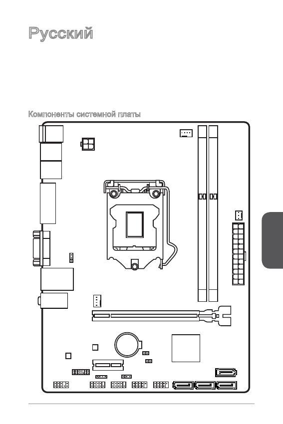
Благодарим вас за выбор системной платы серии H8M-P33/ H8M-E33/ H87M-
P33/ H87M-E33/ B85M-P33/ B85M-E33 (MS-787 v.X) Micro-ATX. Материнские
платы серии H8M-P33/ H8M-E33/ H87M-P33/ H87M-E33/ B85M-P33/
B85M-E33 на базе чипсета Intel H8/ H87/ B85 и обеспечивают оптимальную
производительность системы. Серия H8M-P33/ H8M-E33/ H87M-P33/
H87M-E33/ B85M-P33/ B85M-E33 обеспечивает высокую производительность
и является профессиональной платформой для настольных ПК, благодаря
совместимости с усовершенствованным процессором Intel LGA50.
Компоненты системной платы
Русский
00
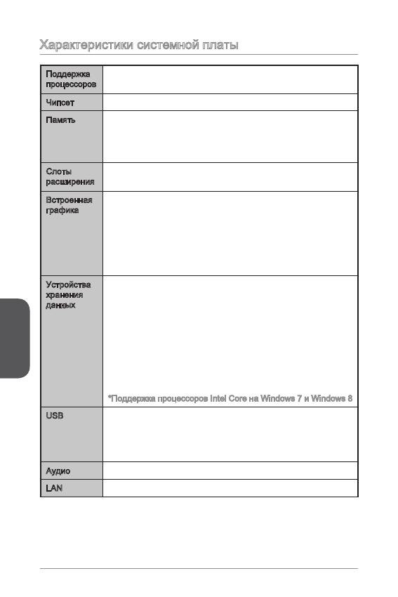
Характеристики системной платы
Поддержка
процессоров
Поддержка процессоров Intel
®
Core™ i7 / Core™ i5 / Core™
i3 / Pentium
®
/ Celeron
®
4-го поколения для сокета LGA 50
■
Чипсет Intel
®
H8/ H87/ B85 Express■
Память 2x DDR3 слота памяти с поддержкой до 6ГБ
Поддержка DDR3 600/ 333/ 066 МГц
Двухканальная архитектура памяти
Поддержка non-ECC, небуферизованной памяти
■
■
■
■
Слоты
расширения
x слот PCIe x6 (дополнительлно)
x слот PCIe 2.0 x
■
■
Встроенная
графика
x порт HDMI (дополнительлно), с поддержкой
x порт DVI-D (дополнительлно), с поддержкой
максимального разрешения 920x200 @ 60Гц, 24bpp
x порт VGA, с поддержкой максимального разрешения
920x200 @ 60Гц, 24bpp
■
■
■
Устройства
хранения
данных
Чипсет Intel H8/ H87/ B85 Express
4x портов SATA (дополнительно)
Поддержка RAID 0, RAID, RAID 5 и RAID 0
(дополнительно)
Поддержка Технологии Intel Smart Response
(дополнительно)*
Поддержка Технологии Intel Rapid Start
(дополнительно)*
Поддержка Технологии Intel Smart Connect
(дополнительно)*
*Поддержка процессоров Intel Core на Windows 7 и Windows 8
■
—
—
—
—
—
USB Чипсет Intel H8/ H87/ B85 Express
2x портов USB 3.0 на задней панели
8x портов USB 2.0 (4 порта на задней панели, 4 порта
доступны через внутренние USB разъемы*)
■
—
—
Аудио Realtek
®
ALC887 Codec■
LAN Realtek
®
RTL8G Гигабитный Сетевой контроллер■
Русский
0
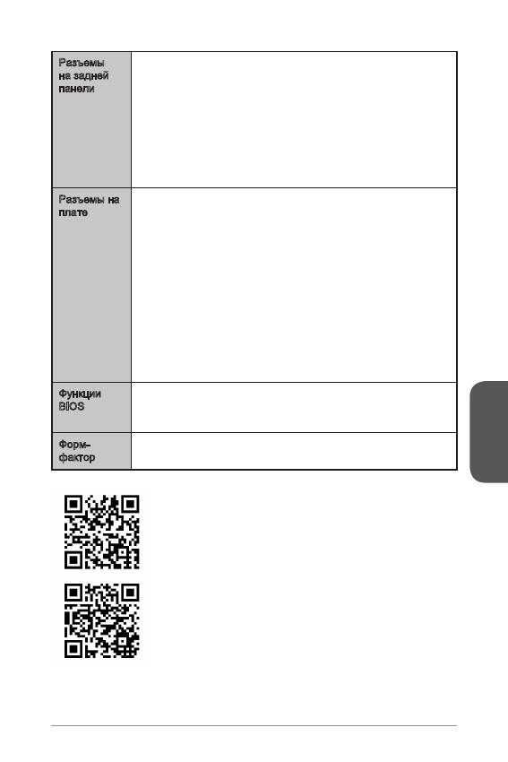
Разъемы
на задней
панели
x порт PS/2 клавиатуры
x порт PS/2 мыши
4x портов USB 2.0
2x порта USB 3.0
x порт HDMI (дополнительно)
x порт DVI-D (дополнительно)
x порт VGA
x порт LAN (RJ45)
3x аудиоразъемов
■
■
■
■
■
■
■
■
■
Разъемы на
плате
x 24-
контактный ATX основной разъем питания
x 4-
контактный ATX 2В разъем питания
4x разъемов SATA
2x разъемов USB 2.0 (Поддержка 4 дополнительных
портов USB 2.0)
x 4-
контактный разъем вентилятора ЦП
x 4-
контактный разъем вентилятора системы
x 3-
контактный разъем вентилятора системы
x аудиоразъем на передней панели
2x разъема панели системы
x разъем датчика открывания корпуса
x перемычка очистки CMOS
2x перемычки USB питания
■
■
■
■
■
■
■
■
■
■
■
■
Функции
BIOS
UEFI AMI BIOS
ACPI 5.0, PnP .0a, SM BIOS 2.7, DMI 2.0
Multi-язык
■
■
■
Форм-
фактор
Micro-ATX Форм-факторы
8.9 дюймов x 6.8 дюймов (22.6 см x 7.3 см)
■
■
Последние сведения о поддержке ЦП см. на веб-
странице http://www.msi.com/service/cpu-support/
Дополнительные сведения о совместимых компонентах
см. на веб-странице
http://www.msi.com/service/test-report/
Русский
02
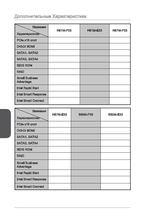
Дополнительные Характеристики
Названия
Характеристики
H8M-P33 H8M-E33 H87M-P33
PCIe x6 слот Gen2 Gen2 Gen3
DVI-D/ HDMI DVI-D HDMI DVI-D
SATA, SATA2 SATA 6Гб/с SATA 6Гб/с SATA 6Гб/с
SATA3, SATA4 SATA 3Гб/с SATA 3Гб/с SATA 6Гб/с
BIOS ROM 64Mб 64Mб 28Mб
RAID Не поддерживает Не поддерживает Поддержка
Small Business
Advantage
Не поддерживает Не поддерживает Поддержка
Intel Rapid Start Не поддерживает Не поддерживает Поддержка
Intel Smart Response Не поддерживает Не поддерживает Поддержка
Intel Smart Connect
Поддержка Поддержка Поддержка
Названия
Характеристики
H87M-E33 B85M-P33 B85M-E33
PCIe x6 слот Gen3 Gen3 Gen3
DVI-D/ HDMI HDMI DVI-D HDMI
SATA, SATA2 SATA 6Гб/с SATA 6Гб/с SATA 6Гб/с
SATA3, SATA4 SATA 6Гб/с SATA 3Гб/с SATA 3Гб/с
BIOS ROM 28Mб 28Mб 28Mб
RAID
Поддержка Не поддерживает Не поддерживает
Small Business
Advantage
Поддержка Поддержка Поддержка
Intel Rapid Start Поддержка Поддержка Поддержка
Intel Smart Response
Поддержка Не поддерживает Не поддерживает
Intel Smart Connect
Поддержка Поддержка Поддержка
Русский
03
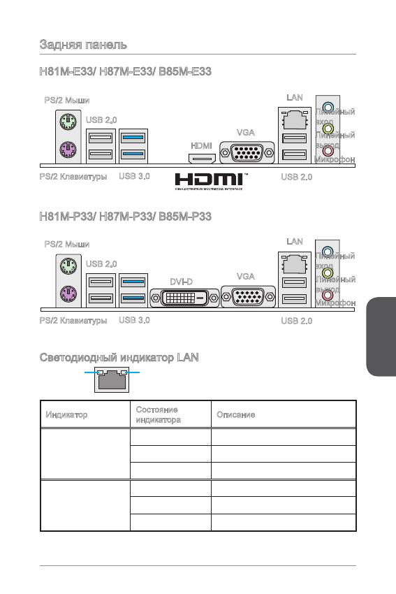
Задняя панель
Светодиодный индикатор LAN
LINK/ACT
LED
SPEED
LED
Индикатор
Состояние
индикатора
Описание
Link/ Activity LED
(Подключение/
Работа индикатора)
Выкл. Не подключен
Желтый Подключен
Мигает Передача данных
Speed LED
(Скорость
передачи данных)
Выкл. 0 Мбит/с подключение
Зеленый 00 Мбит/с подключение
Оранжевый Гбит/с подключение
H8M-E33/ H87M-E33/ B85M-E33
H8M-P33/ H87M-P33/ B85M-P33
PS/2 Мыши
PS/2 Клавиатуры
USB 2.0
USB 3.0
HDMI
VGA
Линейный
вход
Линейный
выход
Микрофон
USB 2.0
LAN
PS/2 Мыши
PS/2 Клавиатуры
USB 2.0
USB 3.0
DVI-D
VGA
Линейный
вход
Линейный
выход
Микрофон
USB 2.0
LAN
Русский
04
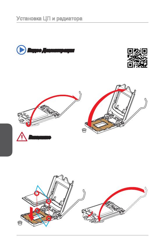
Установка ЦП и радиатора
При установке процессоора обязательно установите радиатор ЦП.Радиатор ЦП
предупреждает перегревание и обеспечивает стабильность работы системы.
Ниже представлены инструкции по правильной установке процессора и
радиатора ЦП.Неправильная установка приводит к выходу из строя процессора
и материнской платы.
. Отцепите и полностью поднимите рычаг фиксации.
2. При подъеме рычага фиксации автоматически поднимается прижимная
пластина.
Внимание
Не трогайте контакты разъема или нижней части процессора.
Видео Демонстрация
Смотрите видео,чтобы узнать как установить процессор и кулер:
http://youtu.be/bf5La099urI
Ключи совмещения
Выемки процессора
3. Выравняйте выемки на процессоре к ключами совмещения на сокете.
Опустите процессор вниз, без наклона или движения процессора в сокете.
Проверьте надежность установки процессора в сокете.
4. Закройте и сдвиньте прижимную пластину под ручку ужержания. Закройте и
зацепите рычаг фиксации.
Русский
05
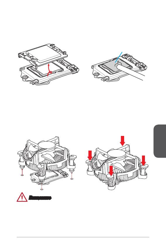
Термопаста
Внимание
Перед включением системы проверьте герметичность соединения между
процессором и радиатором.
Если процессор не установлен, всегда защищайте контакты процессорного
сокета пластиковой крышкой.
Если вы приобрели отдельно процессор и процессорный кулер, подробное
описание установки см. в документации в данному кулеру.
•
•
•
5. При нажатии на рычаг фиксации защитная крышка автоматически выскочит
из гнезда процессора. Не выбрасывайте защитную крышку. Всегда
устанавливайте защитную крышку, если процессор вынимается из сокета.
6. Равномерно нанесите тонкий слой термопасты (или термоленту) на
верхнюю крышку процессора. Это позволит увеличить теплопередачу и
предотвратит перегрев процессора.
7.
Найдите разъем для подключения вентилятора ЦП на материнской плате.
8. Установите кулер на материнскую плату, направив его кабель в сторону
разъема для подключения вентилятора.
9. Нажмите на радиатор сверху так, чтобы закрепить четыре защелки в
отверстиях на материнской плате. Нажмите на защелки для закрепления
вентилятора. Каждый из защелок фиксируется с характерным щелчком.
0. Осмотрите материнскую плату и определите правильность закрепления
зажимов.
. И, наконец, подключите кабель вентилятора процессора к разъему
вентилятора на системной плате.
Русский
06
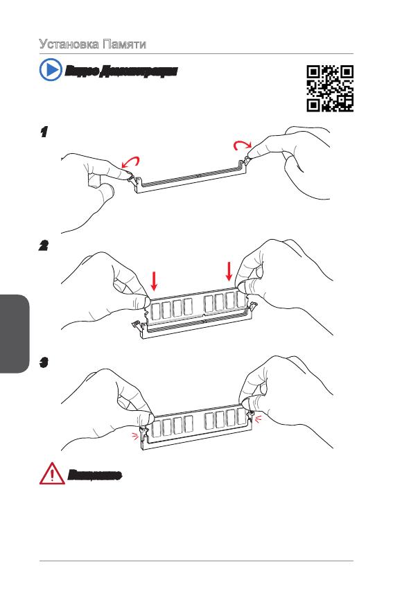
Установка Памяти
Видео Демонстрация
Смотрите видео,чтобы узнать как установить память по
указанному адресу.
2
3
Внимание
Модули DDR3 не взаимозаменяемы с модулями DDR2, стандарт DDR3 не
поддерживает обратную совместимость. Модули памяти DDR3 следует
устанавливать в разъемы DDR3 DIMM.
Для обеспечения стабильной работы системы в двухканальном режиме
устанавливаются модули памяти одинакового типа и емкости.
•
•
Русский
07
Внутренние разъемы
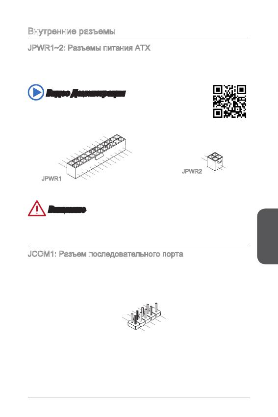
JPWR~2: Разъемы питания ATX
Эти разъемы предназначены для подключения разъема питания ATX. Для
подключения ATX разъема питания совместите кабель питания с разъемом и
прочно закрепите его. При правильном выполнении подключения защелка на
кабеле питания закрепляется в силовом разъеме материнской платы.
Видео Демонстрация
Смотрите видео,чтобы узнать как установить разъем питания.
13.+3.3
V
1.+3.3
V
14.—12V
2.+3.3
V
15.Ground
3
.Ground
16.PS—ON
#
4.+5
V
17.Ground
5
.Ground
18.Ground
6.+5
V
19.Ground
7
.Ground
22.+5
V
10.+12V
20.Res
8.PW
R O
K
23.+5
V
11
.+12V
21.+5
V
9.5VSB
24.Ground
12.+3.3
V
JPWR
4.+12V
2
.Ground
3.+12V
1
.Ground
JPWR2
Внимание
Для обеспечения стабильной работы системной платы проверьте надежность
подключения всех кабелей питания к соответствующему блоку питания АТХ.
JCOM: Разъем последовательного порта
Данный разъем является высокоскоростным последовательным портом
передачи данных 6550А с 6-разрядной передачей FIFO. К этому разъему
можно подключить устройство c последовательным интерфейсом.
1
.
D
C
D
3
.
S
O
U
T
1
0
.
N
o
P
i
n
5
.
G
r
o
u
n
d
7
.
R
T
S
9
.
R
I
8
.
C
T
S
6
.
D
S
R
4
.
D
T
R
2
.
S
I
N
Русский
08
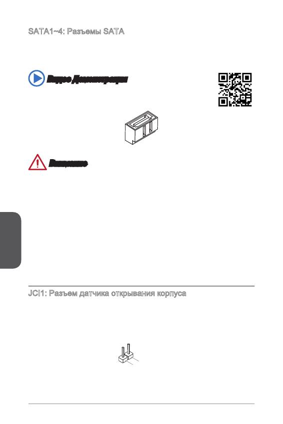
SATA~4: Разъемы SATA
Данный разъем является высокоскоростным интерфейсом SATA. К любому
разъему SATA можно подключить одно устройство SATA. К устройствам
SATA относятся жесткие диски, твердотельные накопители и накопители на
оптических дисках (компакт-диски/ DVD-диски/ Blu-Ray-диски).
Видео Демонстрация
Смотрите видео,чтобы узнать как установить SATA жесткие
диски.
Внимание
Многие устройства SATA требуют подключения к источнику питания с
помощью кабеля питания. К таким устройствам относятся жесткие диски,
твердотельные накопители и накопители на оптических дисках (компакт-
диски/ DVD-диски/ Blu-Ray-диски). Дополнительную информацию можно
получить в руководствах к соответствующим устройствам.
Во многих системных блоках устройства SATA большого размера (в том
числе, жесткие диски, твердотельные накопители и накопители на оптических
дисках) прикрепляются с помощью винтов. Дополнительные инструкции по
установке см. в руководствах к системному блоку или устройству SATA.
Избегайте перегибов кабеля SATA под прямым углом. В противном случае,
возможна потеря данных при передаче.
Кабели SATA оснащены одинаковыми вилками с обеих сторон. Однако для
экономии занимаемого пространства рекомендуется к материнской плате
подключать плоский разъем.
JCI: Разъем датчика открывания корпуса
К этому разъему подключается кабель датчика, установленного в корпусе. Этот
датчик срабатывает при вскрытии системного блока. Система запоминает это
событие и выдает предупреждение на экран. Для отключения предупреждения
необходимо удалить записанное событие в настройках BIOS.
•
•
•
•
Русский
09
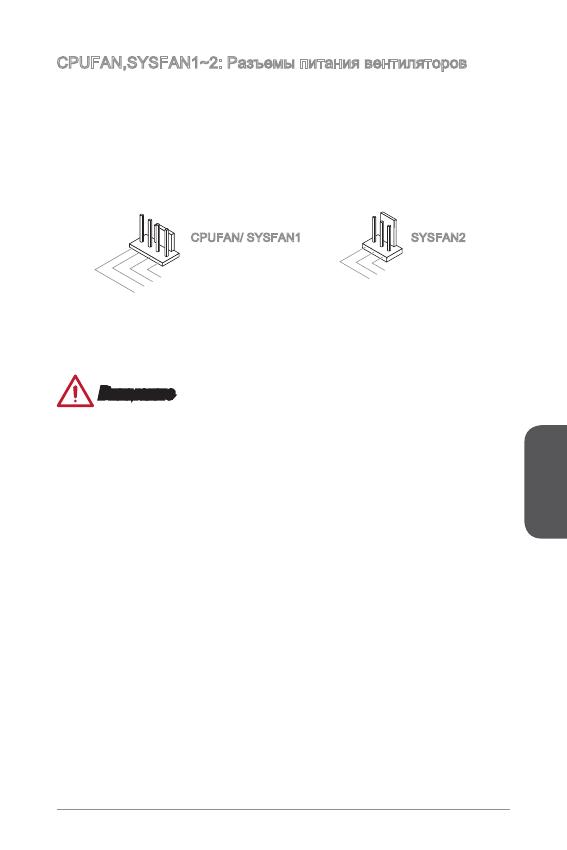
CPUFAN,SYSFAN~2: Разъемы питания вентиляторов
Разъемы питания вентиляторов поддерживают вентиляторы с питанием +2 В.
Если на системной плате установлена микросхема аппаратного мониторинга,
необходимо использовать специальные вентиляторы с датчиками скорости для
использования функции управления вентиляторами. Обязательно подключите
все системные вентиляторы. Некоторые системные вентиляторы невозможно
подключить к материнской плате.Вместо этого они подключаются к источнику
питания напрямую. Системные вентиляторы подключаются к свободным
разъемам для вентиляторов.
1
.Ground
2.+12V
3.Sens
e
4.Speed
C
ontro
l
CPUFAN/ SYSFAN SYSFAN2
Внимание
Для получения кулеров, рекомендованных для охлаждения процессора,
обратитесь на официальный веб-сайт производителя процессора или к
местному поставщику.
Эти разъемы поддерживают функцию управления скоростью вращения
вентиляторов в линейном режиме. Установите утилиту Command Center
для автоматического управления скоростью вращения вентиляторов в
зависимости от температуры процессора и системы.
В том случае, если на материнской плате не достаточно разъемов для
подключения всех системных вентиляторов, вентиляторы подключают
напрямую к источнику питания с помощью переходника.
Перед первой загрузкой проверьте, чтобы кабели не мешали вращению
вентиляторов.
•
•
•
•
Русский
0
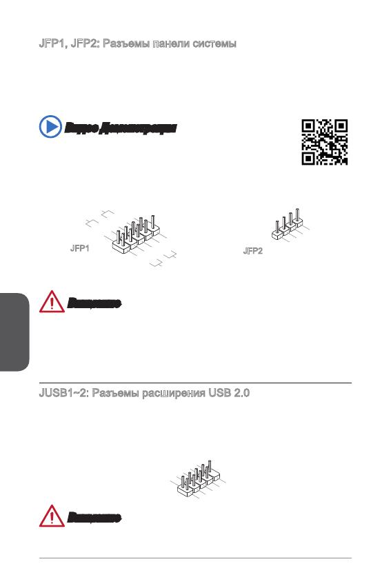
JFP, JFP2: Разъемы панели системы
Эти разъемы служат для подключения кнопок и светодиодных индикаторов,
расположенных на передней панели. Разъем JFP соответствует стандартам
Intel
®
Front Panel I/O Connectivity Design. При установке разъемов передней
панели для удобства используются переходники и кабели, входящие в комплект
поставки. Подключите все провода системного блока к разъемам, а затем
подключите разъемы к материнской плате.
Видео Демонстрация
Смотрите видео,чтобы узнать как подключить разъемы
передней панели.
3.Speaker
4.VCC5
1.Speaker
2.VCC5
1.
+
3.
—
10.No
Pi
n
5.
—
Reset
S
witch
HDD
LE
D
P
ower
S
witch
P
ower
LE
D
7.
+
9.Res erve
d
8.
—
6.
+
4.
—
2.
+
JFP
JFP2
Внимание
На разъемах, выходящих из системного блока, плюсовым проводам
соответствуют контакты, обозначенные небольшими треугольниками.
Для определения правильности направления и расположения служат
вышеуказанные схемы и надписи на дополнительных разъемах.
Большинство кнопок, расположенных на передней панели системного блока,
подключены к разъему JFP.
JUSB~2: Разъемы расширения USB 2.0
Этот разъем служит для подключения таких высокоскоростных периферийных
устройств, как жесткие диски с интерфейсом USB, цифровые камеры, МРЗ
плееры, принтеры, модемы и т. д.
1
.
V
C
C
3
.
U
S
B
0
—
1
0
.
NC
5
.
U
S
B
0
+
7
.
G
r
o
u
n
d
9
.
N
o
P
i
n
8
.
G
r
o
u
n
d
6
.
U
S
B
1
+
4
.
U
S
B
1
—
2
.
V
C
C
Внимание
Помните, что во избежание повреждений необходимо правильно подключать
контакты VCC и GND.
•
•
Русский
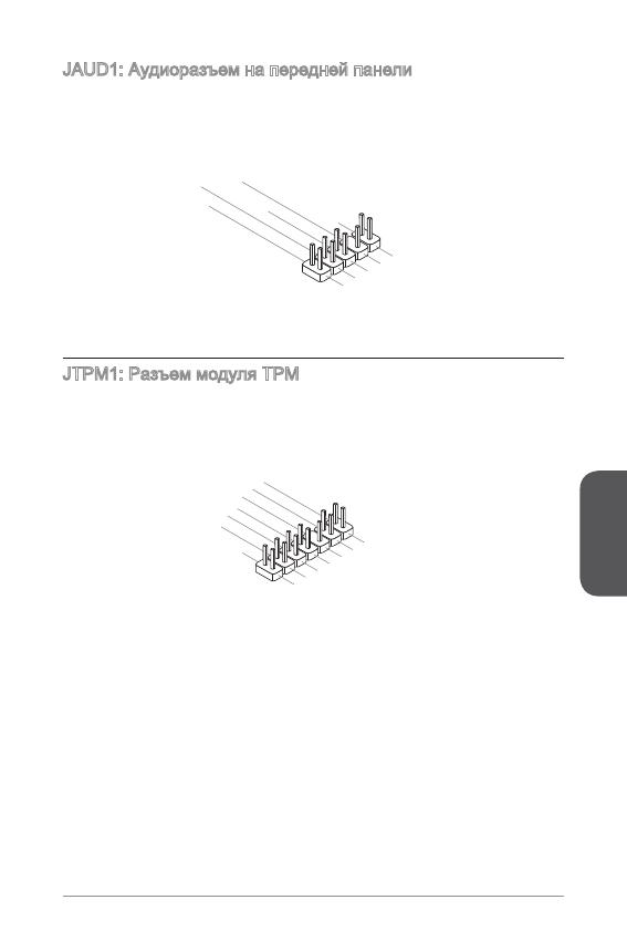
JAUD: Аудиоразъем на передней панели
Этот разъем служит для подключения аудиоразъема на передней панели
системного блока. Этот разъем соответствует стандарту Intel
®
Front Panel I/O
Connectivity Design.
1.MI
C L
3.MI
C R
10.Head
P
hone
Detection
5.Head
P
hone
R
7.SENSE_SEN
D
9.Head
P
hone
L
8.No
Pi
n
6.MI
C D
etection
4.NC
2
.Ground
JTPM: Разъем модуля ТРМ
Данный разъем подключается к модулю ТРМ (Trusted Platform Module).
Дополнительные сведения см. в описании модуля безопасности ТРМ.
10.No
Pi
n
14.Ground
8.5V
P
ower
12.Ground
6.Serial
IR
Q
4.3.3V
P
ower
2.3V
Standby
p
ower
1.LP
C C
loc
k
3.LP
C
Rese
t
5.LP
C a
ddres
s &
data
pin0
7.LP
C a
ddres
s &
data
p
in1
9.LP
C a
ddres
s &
data
pin2
11
.LPC
a
ddres
s &
data
pin3
13.LP
C
Fram
e
Русский
2
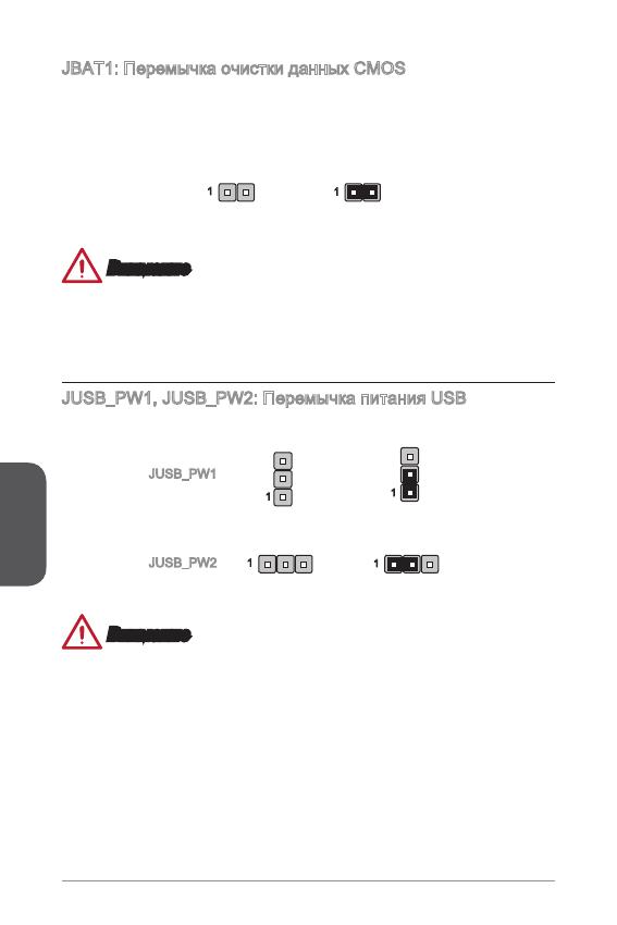
JBAT: Перемычка очистки данных CMOS
На плате установлена CMOS память с питанием от батарейки для хранения
данных о конфигурации системы. С помощью памяти CMOS операционная
система (ОС) автоматически загружается каждый раз при включении. Для
сброса конфигурации системы (очистки данных CMOS памяти), воспользуйтесь
этой перемычкой.
Сохранение
данных
Очистка
данных
Внимание
Очистка CMOS памяти производится замыканием указанных контактов
перемычкой при выключенной режиме. После выполнения очистки разомкните
перемычку. Очистка CMOS памяти во время работы системы не допустима, т.к.
это приведет к выходу материнской платы из строя.
JUSB_PW, JUSB_PW2: Перемычка питания USB
Эти перемычки позволяют включать/ выключать функцию “Активизация через
S3/S4/S5 от USB и PS/2”.
Включен
Выключен (По умолчанию)
Включен
Выключен (По умолчанию)
JUSB_PW
JUSB_PW2
Внимание
Если вы установите перемычку в Включен, блок питания должен быть в
состоянии обеспечить по крайней мере 2A токов
.
Русский
3
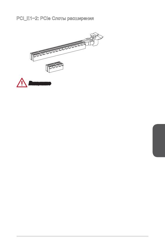
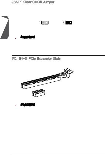
PCI_E~2: PCIe Слоты расширения
Слот PCIe поддерживает платы расширения с интерфейсом PCIe.
PCIe 2.0 x Слот
PCIe 3.0 x6 Слот
Внимание
Перед установкой или извлечением плат расширения убедитесь, что шнур
питания отключен от электрической сети. Прочтите документацию на карту
расширения и выполните необходимые дополнительные аппаратные или
программные изменения для данной карты.
Русский
4
Настройка BIOS
Параметры по умолчанию предлагают оптимальную производительность
для стабильности системы в нормальных условиях. Этот режим может
потребоватья в следующих условиях:
Во время загрузки системы появляется сообщение об ошибке с требованием
запустить SETUP.
В случае необходимости заменить заводские настройки на собственные.
Внимание
Пожалуйста, загрузите заводские настройки для восстановления
оптимальной производительности и стабильности системы, ести система
становится неустойчивой после изменения настроек BIOS. Выберите
«Восстановить настройки по умолчанию» и нажмите <Enter> в BIOS для
загрузки настройки по умолчанию.
Если вы не знакомы с настройками BIOS, мы рекомендуем сохранить
настройки по умолчанию для избежания возможности повреждения системы
или неудачи загрузки из-за неуместного конфигурирования BIOS.
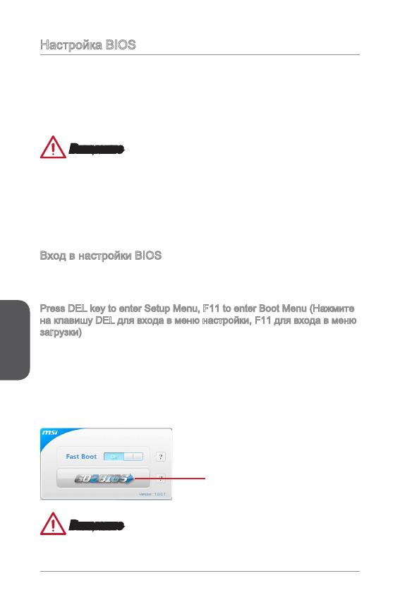
Вход в настройки BIOS
Включите компьютер и дождитесь начала процедуры самотестирования POST
(Power On Self Test). При появлении на экране сообщения, приведенного ниже,
нажмите клавишу <DEL> для запуска программы настройки:
Press DEL key to enter Setup Menu, F to enter Boot Menu (Нажмите
на клавишу DEL для входа в меню настройки, F для входа в меню
загрузки)
Если вы не успели нажать клавишу до отображения сообщения и по-прежнему
требуется войти в программу настройки, перезапустите систему, либо
включив и выключив ее, либо нажав кнопку RESET. Можно также выполнить
перезагрузку, одновременно нажав клавиши <Ctrl>+<Alt>+<Delete>.
MSI также дополнительно предоставляет два метода для входа в настройки
BIOS. Вы можете нажать “GO2BIOS” на экране в утилите “MSI Fast Boot” или
нажать физическую кнопку “GO2BIOS» (опционально) на материнской плате для
непосредственно входа в настройки BIOS при следующей загрузке.
Нажмите «GO2BIOS» на экране
утилиты «MSI Fast Boot».
Внимание
Не забудьте установить “MSI Fast Boot” до того как войти в настройки BIOS.
■
■
•
•
Русский
5
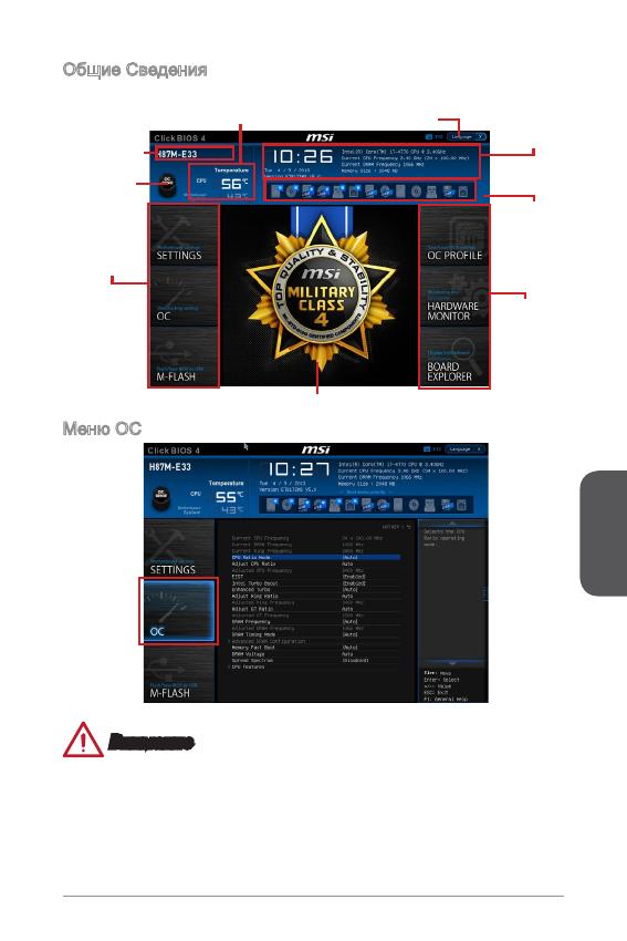
Общие Сведения
После входа в BIOS отображается следующий экран.
Выбор
меню BIOS
Мониторинг температур
Системная
Информация
Приоритет
загрузочных
устройств
Экран просмотра раздела
Выбор
меню BIOS
Язык
Кнопка Virtual
OC Genie
Название
модели
Меню OC
Внимание
Разгонять ПК вручную рекомендуется только опытным пользователям.
Производитель не гарантирует успешность разгона. Неправильное
выполнение разгона может привести к аннулированию гарантии и серьезному
повреждению оборудования.
Неопытным пользователям, рекомендуется использовать OC Genie.
•
•
•
Русский
6
Current CPU/ DRAM/ Ring Frequency
Эти элементы показывают текущие частоты установленного процессора,
памяти и шины Ring. Эти значения нельзя изменять.
CPU Ratio Mode [Auto]
Выбор множителя процессора.
[Auto] Этот параметр будет настроен автоматически с помощью
BIOS.
[Fixed Mode] Фиксирует множитель процессора.
[Dynamic Mode] Множитель процессора будет меняться в зависимости от
загрузки процессора.
Adjust CPU Ratio [Auto]
Задание множителя процессора для установки его тактовой частоты
процессора. Изменение данного параметра возможно только в том случае, если
процессор поддерживает данную функцию.
Adjusted CPU Frequency
Показывает текущую частоту ЦП. Это значение нельзя изменять.
EIST [Enabled]
Включение или выключение технологии Enhanced Intel
®
SpeedStep.
Intel Turbo Boost [Enabled]
Включение или выключение Intel
®
Turbo Boost. Этот пункт появляется, когда
установленный процессор поддерживает данную функцию.
[Enabled] Включение этой функции приводит к автоматическому
увеличению производительности процессора.
[Disabled] Функция выключена.
Enhanced Turbo [Auto]
Функция Enhanced Turbo позволяет увеличивать частоту на всех ядрах
процессора.
[Auto] Этот параметр будет настроен автоматически с помощью
BIOS.
[Enabled] Увеличение частоты всех процессорных ядер до
максимального значения.
[Disabled] Функция выключена.
Adjust Ring Ratio [Auto]
Установка множителя шины Ring. Диапазон допустимых значений зависит от
установленного процессора.
Adjusted Ring Frequency
Показывает скорректированную частоту шины Ring. Это значение нельзя
изменять.
Adjust GT Ratio [Auto]
Установка множителя для интегрированной графики. Диапазон допустимых
значений зависит от установленного процессора.
▶
▶
▶
▶
▶
▶
▶
▶
▶
▶
Русский
7
Adjusted GT Frequency
Показывает настроенную частоту интегрированной графики. Это значение
нельзя изменять.
DRAM Frequency [Auto]
Установка частоты памяти (DRAM). Обратите внимание, что возможность
успешного разгона не гарантируется.
Adjusted DRAM Frequency
Показывает текущую частоту DRAM. Это значение нельзя изменять.
DRAM Timing Mode [Auto]
Режимы таймингов памяти.
[Auto] Временные параметры DRAM устанавливаются на основе
SPD (Serial Presence Detect) модуля памяти.
[Link] Позволяет пользователю настроить тайминги DRAM вручную
для всех каналов памяти.
[UnLink] Позволяет пользователю настроить тайминги DRAM вручную
для соответствующего канала памяти.
Advanced DRAM Conguration
Нажмите <Enter> для входа в подменю. Данное подменю будет доступно после
установки [Link] или [Unlink] в режиме “DRAM Timing Mode”. Пользователь
может настроить тайминги для каждого канала памяти. Система может
работать нестабильно или не загружается после изменения тамингов памяти.
Если система работает нестабильно, пожалуйста, очистите данные CMOS
и восстановите настройки по умолчанию. (см. перемычка очистки данных
CMOS/раздел кнопки для очистки данных CMOS и вход в BIOS, чтобы загрузить
настройки по умолчанию.)
Memory Fast Boot [Auto]
Включает или выключает инициализацию тренировки памяти при каждой
загрузке.
[Auto] Этот параметр будет настроен автоматически с помощью
BIOS.
[Enabled] Память будет полностью имитирует настройки при первой
инициализации и тренировке. После этого память не будет
инициализированна с измененными настройками для
ускорения загрузки.
[Disabled] Память будет инициализирована и тренирована при каждой
загрузке.
DRAM Voltage [Auto]
Установка напряжения памяти. Если значение установлено в “Auto”, BIOS
устанавливает напряжения на памяти автоматически. Вы также можете
настроить его вручную.
Spread Spectrum
Данная функция уменьшает EMI (электромагнитные помехи), вызванные
колебаниями импульсного генератора тактовых сигналов.
▶
▶
▶
▶
▶
▶
▶
▶
- Manuals
- Brands
- MSI Manuals
- Motherboard
- H81M-E33 Series
Manuals and User Guides for MSI H81M-E33 Series. We have 3 MSI H81M-E33 Series manuals available for free PDF download: User Manual, Manual
![]()
Copyright Notice
The material in this document is the intellectual property of MICRO-STAR INTERNATIONAL. We take every care in the preparation of this document, but no guarantee is given as to the correctness of its contents. Our products are under continual improvement and we reserve the right to make changes without notice.
Trademarks
All trademarks in this manual are properties of their respective owners.
MSI® is registered trademark of Micro-Star Int’l Co.,Ltd.
NVIDIA® is registered trademark of NVIDIA Corporation.
ATI® is registered trademark of AMD Corporation.
AMD® is registered trademarks of AMD Corporation.
Intel® is registered trademarks of Intel Corporation.
Windows® is registered trademarks of Microsoft Corporation.
AMI® is registered trademark of American Megatrends Inc.
Award® is a registered trademark of Phoenix Technologies Ltd.
Sound Blaster® is registered trademark of Creative Technology Ltd.
Realtek® is registered trademark of Realtek Semiconductor Corporation.
JMicron® is registered trademark of JMicron Technology Corporation.
Netware® is registered trademark of Novell, Inc.
Lucid® is trademark of LucidLogix Technologies, Ltd.
VIA® is registered trademark of VIA Technologies, Inc.
ASMedia® is registered trademark of ASMedia Technology Inc.
iPad, iPhone, and iPod are trademarks of Apple Inc.
Qualcomm Atheros and Killer are trademarks of Qualcomm Atheros Inc.
|
Revision |
History |
|
|
Revision |
Revision History |
Date |
|
V2.0 |
First release |
2013/08 |
G52-78461X3
Preface
Safety Instructions
|
Preface |
Always read the safety instructions carefully. |
|
|
Keep this User’s Manual for future reference. |
||
|
Keep this equipment away from humidity. |
||
|
Lay this equipment on a reliable flat surface before setting it up. |
||
|
The openings on the enclosure are for air convection hence protects the |
||
|
equipment from overheating. DO NOT COVER THE OPENINGS. |
||
|
Make sure the voltage of the power source is at 110/220V before connecting the |
||
|
equipment to the power inlet. |
||
|
Place the power cord such a way that people can not step on it. Do not place |
||
|
anything over the power cord. |
||
|
Always Unplug the Power Cord before inserting any add-on card or module. |
||
|
All cautions and warnings on the equipment should be noted. |
||
|
Never pour any liquid into the opening that can cause damage or cause electrical |
||
|
shock. |
||
|
If any of the following situations arises, get the equipment checked by service |
||
|
personnel: |
||
|
The power cord or plug is damaged. |
||
|
Liquid has penetrated into the equipment. |
||
|
The equipment has been exposed to moisture. |
||
|
The equipment does not work well or you can not get it work according to |
||
|
User’s Manual. |
||
|
The equipment has been dropped and damaged. |
||
|
The equipment has obvious sign of breakage. |
||
|
DO NOT LEAVE THIS EQUIPMENT IN AN ENVIRONMENT ABOVE 60oC |
||
|
(140oF), IT MAY DAMAGE THE EQUIPMENT. |
Battery Information
European Union:
Batteries, battery packs, and accumulators should not be disposed of as unsorted household waste. Please use the public collection system to return, recycle, or treat them in compliance with the local regulations.
Taiwan:
For better environmental protection, waste batteries should be collected separately for recycling or special disposal.
California, USA:
The button cell battery may contain perchlorate material and requires special handling when recycled or disposed of in California.
For further information please visit: http://www.dtsc.ca.gov/hazardouswaste/perchlorate/
CAUTION: There is a risk of explosion, if battery is incorrectly replaced.
Replace only with the same or equivalent type recommended by the manufacturer.

FCC
 -B Radio Frequency
 Interference
 Statement
This equipment has been tested and found to comply with the limits for a Class B digital device, pursuant to Part 15 of the FCC Rules. These limits are designed to provide reasonable protection against harmful interference in a residential installation. This equipment generates, uses and can radiate radio frequency
energy and, if not installed and used in accordance with the instructions, may cause harmful interference to radio communications. However, there is no guarantee that interference will not occur in a particular installation. If this equipment does cause harmful interference to radio or television reception, which can be determined
by turning the equipment off and on, the user is encouraged to try to correct the interference by one or more of the measures listed below.
Reorient or relocate the receiving antenna.
Increase the separation between the equipment and receiver.
Connect the equipment into an outlet on a circuit different from that to which the receiver is connected.
Consult the dealer or an experienced radio/television technician for help. Notice 1
The changes or modifications not expressly approved by the party responsible for compliance could void the user’s authority to operate the equipment.
Notice 2
Shielded interface cables and A.C. power cord, if any, must be used in order to comply with the emission limits.
VOIR LA NOTICE D’INSTALLATION AVANT DE RACCORDER AU RESEAU.
Micro-Star International
MS-7846
This device complies with Part 15 of the FCC Rules. Operation is subject to the following two conditions:
) this device may not cause harmful interference, and
2)this device must accept any interference received, including interference that may cause undesired operation.
CE Conformity
Hereby, Micro-Star International CO., LTD declares that this device is in compliance with the essential safety requirements and other relevant provisions set out in the European Directive.
Preface
Preface
Radiation Exposure
 Statement
This equipment complies with FCC radiation exposure limits set forth for an uncontrolled environment. This equipment and its antenna should be installed and operated with minimum distance 20 cm between the radiator and your body. This equipment and its antenna must not be co-located or operating in conjunction with any other antenna or transmitter.
European
 Community Compliance Statement
The equipment complies with the RF Exposure Requirement 1999/519/EC, Council Recommendation of 12 July 1999 on the limitation of exposure of the general public to electromagnetic fields (0–300GHz). This wireless device complies with the R&TTE Directive.
Taiwan Wireless Statements
頻率、加大功率或變更原設計之特性及功能。
無線電通信。低功率射頻電機須忍受合法通信或工業、科學及醫療用電波輻射性電機 設備之干擾。
:
Japan VCCI Class B Statement
B
VCCIB
Korea Warning Statements
Chemical Substances Information
In compliance with chemical substances regulations, such as the EU REACH Regulation (Regulation EC No. 1907/2006 of the European Parliament and the Council), MSI provides the information of chemical substances in products at:
http://www.msi.com/html/popup/csr/evmtprtt_pcm.html


< >
|
(Pb) |
(Hg) |
(Cd) |
(Cr6+) |
(PBB) |
(PBDE) |
||
|
(Battery) |
|||||||
|
/ |
|||||||
|
(Cable/ Connector) |
|||||||
|
/ (Chassis/ Other) |
|||||||
|
( CD, DVD ) |
|||||||
|
(Optical Disk Driver) |
|||||||
|
(Hard Disk Driver) |
|||||||
|
(PCAs)* |
|||||||
|
(I/O Device) |
|||||||
|
( Mouse, Keyboard ) |
|||||||
|
(LCD Panel) |
|||||||
|
(Memory) |
|||||||
|
(Processor and Heatsink) |
|||||||
|
( CD DVD ) |
|||||||
|
(Power Supply) |
|||||||
|
(Remote Control) |
|||||||
|
(Speakers) |
|||||||
|
(TV Tunner) |
|||||||
|
(Web Camera) |
|||||||
|
(Wireless Cards) |
■* (PCB) IC
■: SJ/T113632006
■: SJ/T113632006 EU RoHS
■<
> EPUP (Environmental Protection Use Period)
■EPUP -(SJ/Z 11388-2009) EPUP ,
Preface
Preface
WEEE Statement
WEEE (Waste Electrical and Electronic Equipment)
ENGLISH


To protect the global environment and as an environmentalist, MSI must remind you that…
Under the European Union (“EU”) Directive on Waste Electrical and
Electronic Equipment, Directive 2002/96/EC, which takes effect on August 13, 2005, products of “electrical and electronic equipment” cannot be discarded as municipal wastes anymore, and manufacturers of covered electronic equipment will be obligated to take back such products at the end of their useful life. MSI will comply with the product take back requirements at the end of life of MSI-branded products that are sold into the EU. You can return these products to local collection points.
DEUTSCH
Hinweis von MSI zur Erhaltung und Schutz unserer Umwelt
Gemäß der Richtlinie 2002/96/EG über Elektround Elektronik-Altgeräte dürfen Elektround Elektronik-Altgeräte nicht mehr als kommunale Abfälle entsorgt werden. MSI hat europaweit verschiedene Sammelund Recyclingunternehmen beauftragt, die in die Europäische Union in Verkehr gebrachten Produkte, am Ende seines Lebenszyklus zurückzunehmen. Bitte entsorgen Sie dieses Produkt zum gegebenen Zeitpunkt ausschliesslich an einer lokalen Altgerätesammelstelle in Ihrer Nähe.
FRANÇAIS

En tant qu’écologiste et afin de protéger l’environnement, MSI tient à rappeler ceci…
Au sujet de la directive européenne (EU) relative aux déchets des équipement électriques et électroniques, directive 2002/96/EC, prenant effet le 13 août 2005, que les produits électriques et électroniques ne peuvent être déposés dans les décharges ou tout simplement mis à la poubelle. Les fabricants de ces équipements seront obligés de récupérer certains produits en fin de vie. MSI prendra en compte cette exigence relative au retour des produits en fin de vie au sein de la communauté européenne. Par conséquent vous pouvez retourner localement ces matériels dans les points de collecte.
РУССКИЙ
Компания MSI предпринимает активные действия по защите окружающей среды, поэтому напоминаем вам, что….
В соответствии с директивой Европейского Союза (ЕС) по предотвращению загрязнения окружающей среды использованным электрическим и электронным оборудованием (директива WEEE 2002/96/EC), вступающей в силу 13
августа 2005 года, изделия, относящиеся к электрическому и электронному оборудованию, не могут рассматриваться как бытовой мусор, поэтому производители вышеперечисленного электронного оборудования обязаны принимать его для переработки по окончании срока службы. MSI обязуется соблюдать требования по приему продукции, проданной под маркой MSI на территории EC, в переработку по окончании срока службы. Вы можете вернуть эти изделия в специализированные пункты приема.

ESPAÑOL


MSI como empresa comprometida con la protección del medio ambiente, recomienda:
Bajo la directiva 2002/96/EC de la Unión Europea en materia de desechos y/o equipos electrónicos, con fecha de rigor desde el 13 de agosto de 2005, los productos clasificados como “eléctricos y equipos electrónicos” no pueden ser depositados en los contenedores habituales de su municipio, los fabricantes de equipos electrónicos, están obligados a hacerse cargo de dichos productos al termino de su período de vida. MSI estará comprometido con los términos de recogida de sus productos vendidos en la Unión Europea al final de su periodo de vida. Usted debe depositar estos productos en el punto limpio establecido por el ayuntamiento de su localidad o entregar a una empresa autorizada para la recogida de estos residuos.
NEDERLANDS
Om het milieu te beschermen, wil MSI u eraan herinneren dat….
De richtlijn van de Europese Unie (EU) met betrekking tot Vervuiling van Electrische en Electronische producten (2002/96/EC), die op 13 Augustus 2005 in zal gaan kunnen niet meer beschouwd worden als vervuiling. Fabrikanten van dit soort producten worden verplicht om producten retour te nemen aan het eind van hun levenscyclus. MSI zal overeenkomstig de richtlijn handelen voor de producten
die de merknaam MSI dragen en verkocht zijn in de EU. Deze goederen kunnen geretourneerd worden op lokale inzamelingspunten.
SRPSKI
Da bi zaštitili prirodnu sredinu, i kao preduzeće koje vodi računa o okolini i prirodnoj sredini, MSI mora da vas podesti da…
Po Direktivi Evropske unije (“EU”) o odbačenoj ekektronskoj i električnoj opremi, Direktiva 2002/96/EC, koja stupa na snagu od 13. Avgusta 2005, proizvodi koji spadaju pod “elektronsku i električnu opremu” ne mogu više biti odbačeni kao običan otpad i proizvođači ove opreme biće prinuđeni da uzmu natrag ove proizvode na kraju njihovog uobičajenog veka trajanja. MSI će poštovati zahtev o preuzimanju ovakvih proizvoda kojima je istekao vek trajanja, koji imaju MSI oznaku i koji su prodati u EU. Ove proizvode možete vratiti na lokalnim mestima za prikupljanje.
POLSKI

Aby chronić nasze środowisko naturalne oraz jako firma dbająca o ekologię, MSI przypomina, że…
Zgodnie z Dyrektywą Unii Europejskiej (“UE”) dotyczącą odpadów produktów elektrycznych i elektronicznych (Dyrektywa 2002/96/EC), która wchodzi w życie 13 sierpnia 2005, tzw. “produkty oraz wyposażenie elektryczne i elektroniczne “ nie mogą być traktowane jako śmieci komunalne, tak więc producenci tych produktów będą zobowiązani do odbierania ich w momencie gdy produkt jest wycofywany z użycia. MSI wypełni wymagania UE, przyjmując produkty (sprzedawane na terenie Unii Europejskiej) wycofywane z użycia. Produkty MSI będzie można zwracać w wyznaczonych punktach zbiorczych.
Preface
Preface
TÜRKÇE

Çevreci özelliğiyle bilinen MSI dünyada çevreyi korumak için hatırlatır:
Avrupa Birliği (AB) Kararnamesi Elektrik ve Elektronik Malzeme Atığı, 2002/96/EC Kararnamesi altında 13 Ağustos 2005 tarihinden itibaren geçerli olmak üzere, elektrikli ve elektronik malzemeler diğer atıklar gibi çöpe atılamayacak ve bu elektonik cihazların üreticileri, cihazların kullanım süreleri bittikten sonra ürünleri geri toplamakla yükümlü olacaktır. Avrupa Birliği’ne satılan MSI markalı ürünlerin kullanım süreleri bittiğinde MSI ürünlerin geri alınması isteği ile işbirliği içerisinde olacaktır. Ürünlerinizi yerel toplama noktalarına bırakabilirsiniz.
ČESKY
Záleží nám na ochraně životního prostředí — společnost MSI upozorňuje…
Podle směrnice Evropské unie (“EU”) o likvidaci elektrických a elektronických výrobků 2002/96/EC platné od 13. srpna 2005 je zakázáno likvidovat “elektrické a elektronické výrobky” v běžném komunálním odpadu a výrobci elektronických
výrobků, na které se tato směrnice vztahuje, budou povinni odebírat takové výrobky zpět po skončení jejich životnosti. Společnost MSI splní požadavky na odebírání výrobků značky MSI, prodávaných v zemích EU, po skončení jejich životnosti. Tyto výrobky můžete odevzdat v místních sběrnách.
MAGYAR
Annak érdekében, hogy környezetünket megvédjük, illetve környezetvédőként fellépve az MSI emlékezteti Önt, hogy …
Az Európai Unió („EU”) 2005. augusztus 13-án hatályba lépő, az elektromos és elektronikus berendezések hulladékairól szóló 2002/96/EK irányelve szerint az elektromos és elektronikus berendezések többé nem kezelhetőek lakossági hulladékként, és az ilyen elektronikus berendezések gyártói kötelessé válnak az ilyen termékek visszavételére azok hasznos élettartama végén. Az MSI betartja a termékvisszavétellel kapcsolatos követelményeket az MSI márkanév alatt az EU-n belül értékesített termékek esetében, azok élettartamának végén. Az ilyen termékeket a legközelebbi gyűjtőhelyre viheti.
ITALIANO

Per proteggere l’ambiente, MSI, da sempre amica della natura, ti ricorda che….
In base alla Direttiva dell’Unione Europea (EU) sullo Smaltimento dei Materiali Elettrici ed Elettronici, Direttiva 2002/96/EC in vigore dal 13 Agosto 2005, prodotti appartenenti alla categoria dei Materiali Elettrici ed Elettronici non possono più essere eliminati come rifiuti municipali: i produttori di detti materiali saranno obbligati a ritirare ogni prodotto alla fine del suo ciclo di vita. MSI si adeguerà a tale Direttiva ritirando tutti i prodotti marchiati MSI che sono stati venduti all’interno dell’Unione Europea alla fine del loro ciclo di vita. È possibile portare i prodotti nel più vicino punto di raccolta

Contents
English 11
Motherboard Specifications 12 Optional Specifications 14 Back Panel 15 CPU & Heatsink Installation 16 Memory Installation 18 Internal Connectors 19 BIOS Setup 25
33
343637 CPU 384041 BIOS 47
Français 55
Spécifications 56 Spécifications en option 58 Panneau Arrière 59 Installation du CPU et son ventilateur 60 Installation de mémoire 62 Connecteurs internes 63 Configuration BIOS 69
Deutsch 77
Spezifikationen 78 Optionale Spezifikationen 80 Rücktafel-Übersicht 81 CPU & Kühlkörper Einbau 82 Speicher 84 Interne Anschlüsse 85 BIOS Setup 91
Preface

Preface
Русский 99
Характеристики материнской платы 100 Дополнительные характеристики 102 Задняя панель 103 Установка ЦП и радиатора 104 Установка памяти 106 Внутренние разъемы 107 Настройка BIOS 113
121
122124125 CPU & 126128129 BIOS Setup 135
141
142145CPU 146148149 BIOS 155
161
162164 I/O 165 CPU 166168169 BIOS 175
10
![]()
English


Thank you for choosing the H81M-P33 V2/ H81M-E33 V2/ B85M-P33 V2/ B85M-E33 V2 Series (MS-7846 v2.X) Micro-ATX motherboard. The H81M-P33 V2/ H81M-E33 V2/ B85M-P33 V2/ B85M-E33 V2 Series motherboards are based on Intel H81/ B85 chipset for optimal system efficiency. Designed to fit the advanced Intel LGA1150 processor, the H81M-P33 V2/ H81M-E33 V2/ B85M-P33 V2/ B85M-E33 V2 Series motherboards deliver a high performance and professional desktop platform solution.
Layout
|
Top : mouse / keyboard |
|
|
Bottom: USB2.0 ports |
CPUFAN |
|
JPWR2 |
|
SYSFAN2 |
|
|
Top : |
|
|
Parallel port (optional) |
|
|
Bottom: |
|
|
DVI-D port (optional) |
JPWR1 |
|
HDMI port (optional) |
|
|
VGA port |
|
|
USB3.0 ports |
|
(optional) |
||||||||||||||||||||||||||
|
Top: LAN Jack |
DIMM1 |
DIMM2 |
||||||||||||||||||||||||
|
Bottom: USB2.0 |
ports |
|||||||||||||||||||||||||
|
T:Line-In |
2 |
|||||||||||||||||||||||||
|
M:Line-Out |
_ |
|||||||||||||||||||||||||
|
B:Mic-In |
SYSFAN1 |
JUSB3 |
||||||||||||||||||||||||
|
PCI_E1 |
||||||||||||||||||||||||||
|
PCI_E2 |
4 |
|||||||||||||||||||||||||
|
SATA3 |
||||||||||||||||||||||||||
|
PCI_E3 |
2 |
|||||||||||||||||||||||||
|
JBAT1 |
JCI1 |
SATA1 |
||||||||||||||||||||||||
|
JFP2 |
||||||||||||||||||||||||||
|
JUSB3_1 (optional) |
||||||||||||||||||||||||||
|
JAUD1 |
JTPM1 |
COM1 |
JUSB2 |
JUSB1 |
JFP1 |
English
11
English
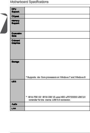
Motherboard Specifications
|
CPU |
■ |
4th Generation Intel® Core™ i7 / Core™ i5 / Core™ i3 / |
|
|
Support |
Pentium® / Celeron® processors for LGA 1150 socket |
||
|
Chipset |
■ |
Intel® H81/ B85 Express Chipset |
|
|
Memory |
■ 2x |
DDR3 memory slots supporting up to 16GB |
|
|
Support |
■ Supports DDR3 1600/ 1333/ 1066 MHz |
||
|
■ |
Dual channel memory architecture |
||
|
■ |
Supports non-ECC, un-buffered memory |
||
|
Expansion |
■ |
1x |
PCIe x16 slot |
|
Slots |
■ |
2x |
PCIe 2.0 x1 slots |
|
Onboard |
■ |
1x |
VGA port, supporting a maximum resolution of 1920×1200 |
|
Graphics |
@ 60Hz, 24bpp |
■1x HDMI port (optional), supporting a maximum resolution of 4096×2160@24Hz, 24bpp/ 2560×1600@60Hz, 24bpp/ 1920×1080@60Hz, 36bpp
■1x DVI-D port (optional), supporting a maximum resolution of 1920×1200 @ 60Hz, 24bpp
|
Storage |
■ Intel H81/ B85 Express Chipset |
—2x SATA 6Gb/s ports (SATA1~2)
—2x SATA 3Gb/s ports (SATA3~4)
—Supports Intel Rapid Start Technology (optional)*
—Supports Intel Smart Connect Technology
* Supports Intel
 Core processors on Windows 7 and Windows 8
|
USB |
■ Intel H81/ B85 Express Chipset |
—4x USB 3.0 ports (2 ports on the back panel, 2 ports available through the internal USB connector*)
—8x USB 2.0 ports (4 ports on the back panel, 4 ports
available through the internal USB connectors)
* H81M
 -P33 V2/ H81M
 -E33
-E33
 V2 uses NEC uPD720202 USB 3.0 controller for the internal
 USB 3.0 connector.
|
Audio |
■ |
Realtek® ALC887 Codec |
|
LAN |
■ |
Realtek® RTL8111G Gigabit LAN controller |
12
|
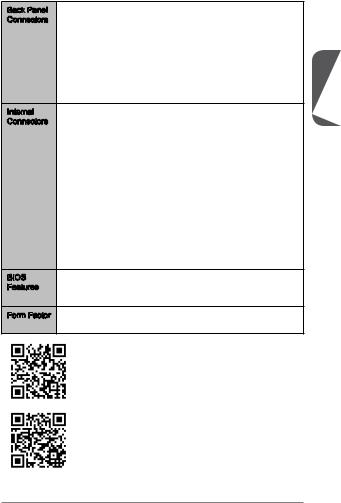
Back Panel |
■ |
1x |
PS/2 keyboard/ mouse port |
|
Connectors |
■ 1x |
VGA port |
|
|
■ |
1x |
Parallel port (optional) |
|
|
■ |
1x |
DVI-D port (optional) |
|
|
■ |
1x |
HDMI port (optional) |
|
|
■ |
4x |
USB 2.0 ports |
|
|
■ |
2x |
USB 3.0 ports |
|
|
■ |
1x |
LAN (RJ45) port |
|
|
■ |
3x audio jacks |
||
|
Internal |
■ |
1x |
24-pin ATX main power connector |
|
Connectors |
■ |
1x |
4-pin ATX 12V power connector |
■2x SATA 6Gb/s connectors
■2x SATA 3Gb/s connectors
■2x USB 2.0 connectors (supports additional 4 USB 2.0 ports)
■1x USB 3.0 connector (supports additional 2 USB 3.0 ports)
■1x 4-pin CPU fan connector
■1x 4-pin system fan connector
■1x 3-pin system fan connector
■1x Front panel audio connector
■1x Serial port connector
■1x TPM connector
■2x System panel connectors
■1x Chassis Intrusion connector
■1x Clear CMOS jumper
|
BIOS |
■ UEFI AMI BIOS |
|
|
Features |
■ |
ACPI 5.0, PnP 1.0a, SM BIOS 2.7, DMI 2.0 |
|
■ |
Multi-language |
|
|
Form Factor |
■ |
Micro-ATX Form Factor |
|
■ |
8.9 in. x 9.0 in. (22.6 cm x 22.8 cm) |
For the latest information about CPU, please visit
http://www.msi.com/service/cpu-support/
For more information on compatible components, please visit http://www.msi.com/service/test-report/
English
13
English
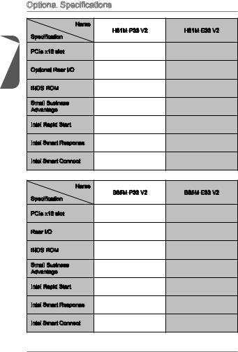
Optional Specifications

 Specifications
|
Name |
H81M—P33 V2 |
H81M—E33 V2 |
|
|
Specification |
|||
|
PCIe x16 slot |
Gen2 |
Gen2 |
|
|
Optional Rear I/O |
Parallel, DVI-D |
HDMI |
|
|
BIOS ROM |
64Mb |
64Mb |
|
|
Small Business |
Not supported |
Not supported |
|
|
Advantage |
|||
|
Intel Rapid Start |
Not supported |
Not supported |
|
|
Intel Smart Response |
Not supported |
Not supported |
|
|
Intel Smart Connect |
Supported |
Supported |
|
|
Name |
B85M—P33 V2 |
B85M—E33 V2 |
|
|
Specification |
|||
|
PCIe x16 slot |
Gen3 |
Gen3 |
|
|
Rear I/O |
Parallel, DVI-D |
HDMI |
|
|
BIOS ROM |
128Mb |
128Mb |
|
|
Small Business |
Supported |
Supported |
|
|
Advantage |
|||
|
Intel Rapid Start |
Supported |
Supported |
|
|
Intel Smart Response |
Not supported |
Not supported |
|
|
Intel Smart Connect |
Supported |
Supported |
14

Back Panel

|
B85M-P33 V2/ H81M-P33 V2 |
|||||
|
PS/2 Mouse/ Keyboard |
Parallel |
LAN |
|||
|
USB 3.0 |
Line-In |
English |
|||
|
Line-Out |
|||||
|
Mic |
|||||
|
USB 2.0 |
DVI-D |
VGA |
USB 2.0 |
|
B85M-E33 V2/ H81M-E33 V2 |
||||
|
PS/2 Mouse/ Keyboard |
LAN |
|||
|
USB 3.0 |
Line-In |
|||
|
HDMI |
Line-Out |
|||
|
Mic |
||||
|
USB 2.0 |
® |
VGA |
USB 2.0 |
LAN
 LED
LED
 Indicator

|
LINK/ACT |
SPEED |
|
|
LED |
LED |
|
|
LED |
LED Status |
Description |
|
Off |
No link |
|
|
Link/ Activity LED |
Yellow |
Linked |
|
Blinking |
Data activity |
|
|
Off |
10 Mbps connection |
|
|
Speed LED |
Green |
100 Mbps connection |
|
Orange |
1 Gbps connection |
15
English
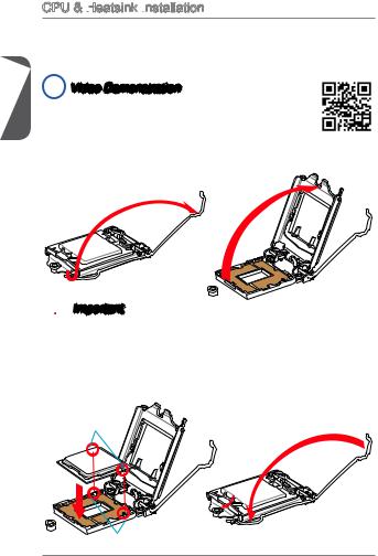
CPU & Heatsink Installation
 Installation
When installing a CPU, always remember to install a CPU heatsink. A CPU heatsink is necessary to prevent overheating and maintain system stability. Follow the steps below to ensure correct CPU and heatsink installation. Wrong installation can damage both the CPU and the motherboard.
 Video Demonstration
Watch the video to learn how to install CPU & heatsink. at the address below.
http://youtu.be/bf5La099urI
1.Push the load lever down to unclip it and lift to the fully open position.
2.The load plate will automatically lift up as the load lever is pushed to the fully open position.
 Important
Do not touch the socket contacts or the bottom of the CPU.
3.Align the notches with the socket alignment keys. Lower the CPU straight down, without tilting or sliding the CPU in the socket. Inspect the CPU to check if it is properly seated in the socket.
4.Close and slide the load plate under the retention knob. Close and engage the load lever.
CPU notches
Alignment Key
16
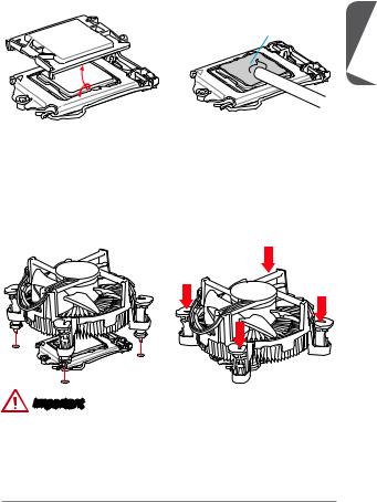
5.When you press down the load lever the PnP cap will automatically pop up from the CPU socket. Do not discard the PnP cap. Always replace the PnP cap if the CPU is removed from the socket.
6.Evenly spread a thin layer of thermal paste (or thermal tape) on the top of the CPU. This will help in heat dissipation and prevent CPU overheating.
Thermal paste
English
7.Locate the CPU fan connector on the motherboard.
8.Place the heatsink on the motherboard with the fan’s cable facing towards the fan connector and the fasteners matching the holes on the motherboard.
9.Push down the heatsink until the four fasteners get wedged into the holes on the motherboard. Press the four fasteners down to fasten the heatsink. As each fastener locks into position a click should be heard.
10.Inspect the motherboard to ensure that the fastener-ends have been properly locked in place.
11.Finally, attach the CPU fan cable to the CPU fan connector on the motherboard.
Important
•Confirm that the CPU heatsink has formed a tight seal with the CPU before booting your system.
•Whenever the CPU is not installed, always protect the CPU socket pins by covering the socket with the plastic cap.
•If you purchased a separate CPU and heatsink/ cooler, Please refer to the documentation in the heatsink/ cooler package for more details about installation.
17
English
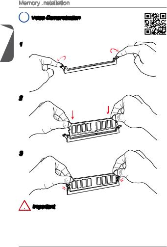
Memory Installation

 Video Demonstration
Watch the video to learn how to install memories at the address below. http://youtu.be/76yLtJaKlCQ
1
2
3
 Important
•DDR3 memory modules are not interchangeable with DDR2, and the DDR3 standard is not backward compatible. Always install DDR3 memory modules in DDR3 DIMM slots.
•To ensure system stability, memory modules must be of the same type and density in Dual-Channel mode.
18
Internal Connectors

 Connectors
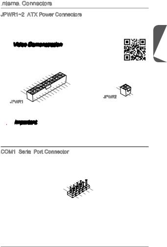
JPWR1~2: ATX Power Connectors
These connectors allow you to connect an ATX power supply. To connect the ATX power supply, align the power supply cable with the connector and firmly press the cable into the connector. If done correctly, the clip on the power cable should be hooked on the motherboard’s power connector.
 Video Demonstration
Watch the video to learn how to install power supply connectors. http://youtu.be/gkDYyR_83I4
|
12. |
||||||||
|
11 |
. +3 |
. |
||||||
|
910. |
||||||||
|
7 |
. |
+12V |
3V |
|||||
|
8 |
||||||||
|
6 . |
||||||||
|
5 . |
||||||||
|
1 |
4 |
. +5 |
||||||
|
3 . |
Ground |
|||||||
|
2 . +5 |
||||||||
|
+3.Ground |
||||||||
|
. |
V |
|||||||
|
. +3. |
||||||||
|
3 |
||||||||
|
3 |
V |
|||||||
|
V |
|
JPWR1 |
. |
— |
||
|
+3.Ground |
||||
|
13. |
— |
ON |
# |
|
|
12V |
||||
|
3 |
||||
|
V |
|
24. |
||
|
23. |
||
|
Ground |
||
|
. +5 |
V |
|
|
+5 |
||
|
+5 |
V |
|
|
V |
 Important
Make sure that all the power cables are securely connected to a proper ATX power supply to ensure stable operation of the motherboard.
COM1: Serial
 Port Connector
This connector is a 16550A high speed communication port that sends/receives 16 bytes FIFOs. You can attach a serial device.
|
1 |
||||||||||
|
0 |
||||||||||
|
8 . |
||||||||||
|
6 |
. N |
|||||||||
|
C |
o |
|||||||||
|
4 |
. |
T |
P |
|||||||
|
D |
S |
i |
||||||||
|
2 |
. |
S |
n |
|||||||
|
D |
R |
|||||||||
|
. |
T |
|||||||||
|
S |
R |
|||||||||
|
I |
||||||||||
|
N |
|
9 |
|||||||||
|
7 |
. |
||||||||
|
R |
|||||||||
|
5 |
. |
I |
|||||||
|
R |
|||||||||
|
3 |
. |
T |
|||||||
|
G |
S |
||||||||
|
1 |
. |
r |
|||||||
|
S |
o |
||||||||
|
. |
O |
u |
|||||||
|
D |
U |
n |
|||||||
|
C |
d |
||||||||
|
T |
|||||||||
|
D |
English
19
English
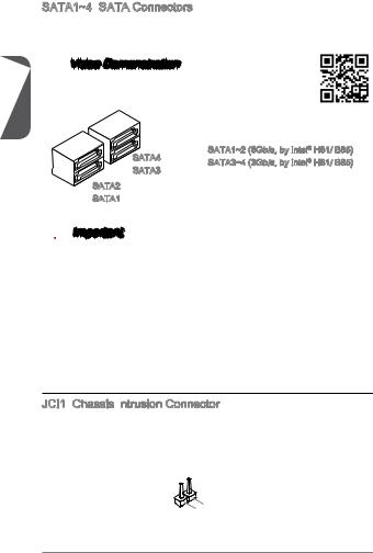
SATA1~4: SATA Connectors
This connector is a high-speed SATA interface port. Each connector can connect to one SATA device. SATA devices include disk drives (HDD), solid state drives (SSD), and optical drives (CD/ DVD/ Blu-Ray).
 Video Demonstration
Watch the video to learn how to Install SATA HDD. http://youtu.be/RZsMpqxythc
|
SATA4 |
SATA1~2 (6Gb/s, by Intel® H81/ B85) |
|
SATA3~4 (3Gb/s, by Intel® H81/ B85) |
|
|
SATA3 |
SATA2
SATA1
 Important
•Many SATA devices also need a power cable from the power supply. Such devices include disk drives (HDD), solid state drives (SSD), and optical drives (CD / DVD / Blu-Ray). Please refer to the device’s manual for further information.
•Many computer cases also require that large SATA devices, such as HDDs, SSDs, and optical drives, be screwed down into the case. Refer to the manual that came with your computer case or your SATA device for further installation instructions.
•Please do not fold the SATA cable at a 90-degree angle. Data loss may result during transmission otherwise.
•SATA cables have identical plugs on either sides of the cable. However, it is recommended that the flat connector be connected to the motherboard for space saving purposes.
JCI1: Chassis Intrusion
 Connector
This connector connects to the chassis intrusion switch cable. If the computer case is opened, the chassis intrusion mechanism will be activated. The system will record this intrusion and a warning message will flash on screen. To clear the warning, you must enter the BIOS utility and clear the record.
|
1 |
||||||
|
2 |
. |
|||||
|
G |
||||||
|
. |
r |
|||||
|
C |
o |
|||||
|
I |
u |
|||||
|
N |
n |
|||||
|
T |
d |
|||||
|
R |
||||||
|
U |
20
![]()
CPUFAN,SYSFAN1~2: Fan
Fan Power Connectors
The fan power connectors support system cooling fans with +12V. If the motherboard has a System Hardware Monitor chipset on-board, you must use a specially designed fan with a speed sensor to take advantage of the CPU fan control. Remember to connect all system fans. Some system fans may not connect to the motherboard and will instead connect to the power supply directly. A system fan can be plugged into any available system fan connector.
 CPUFAN/ SYSFAN1
|
1 |
||
|
2 . |
||
|
+12VGround |
||
|
3 . |
||
|
4 . |
||
|
Sens |
||
|
. |
||
|
Speed |
e |
|
|
C |
||
|
ontrol |
 SYSFAN2
1 . 2 . Ground 3 +12V . No Use
 Important
•Please refer to your processor’s official website or consult your vendor to find recommended CPU heatsink.
•These connectors support Smart Fan Control with liner mode. The Command Center utility can be installed to automatically control the fan speeds according to the CPU’s and system’s temperature.
•If there are not enough ports on the motherboard to connect all system fans, adapters are available to connect a fan directly to a power supply.
•Before first boot up, ensure that there are no cables impeding any fan blades.
JAUD1: Front
Front
 Panel
Panel Audio Connector
This connector allows you to connect the front audio panel located on your computer case. This connector is compliant with the Intel® Front Panel I/O Connectivity Design Guide.
|
10. |
||||||
|
4 |
8 |
|||||
|
. NoHead |
||||||
|
6 |
. |
|||||
|
Pi |
P |
|||||
|
. MI |
||||||
|
2 |
NC |
D |
hone |
|||
|
C n |
||||||
|
. |
||||||
|
Ground |
etection |
Detection |
||||
|
9 |
|||||||||
|
3 . |
. |
||||||||
|
Head |
|||||||||
|
7 |
|||||||||
|
5 . |
|||||||||
|
. MIHeadSENSE |
P |
||||||||
|
. |
R |
||||||||
|
1 |
P |
hone |
|||||||
|
MI |
C |
_ |
|||||||
|
L |
SEN |
L |
|||||||
|
C |
hone |
||||||||
|
R |
D |
English
21
English
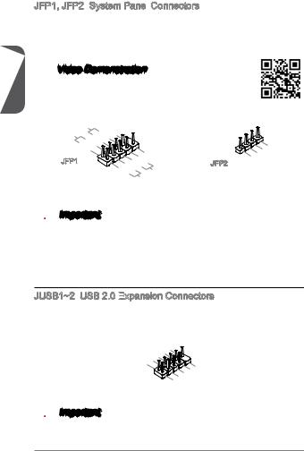
JFP1, JFP2: System Panel
 Connectors
These connectors connect to the front panel switches and LEDs. The JFP1 connector is compliant with the Intel® Front Panel I/O Connectivity Design Guide. When installing the front panel connectors, please use the optional M-Connector to simplify installation. Plug all the wires from the computer case into the M-Connector and then plug the M-Connector into the motherboard.
 Video Demonstration
Watch the video to learn how to Install front panel connectors. http://youtu.be/DPELIdVNZUI
|
P |
||||||||
|
P |
ower |
S |
10. |
|||||
|
ower |
LE |
witch |
No |
|||||
|
8Pi |
||||||||
|
D |
6 |
. n |
||||||
|
— |
||||||||
|
4 |
. |
|||||||
|
+ |
||||||||
|
2 |
. |
|||||||
|
— |
||||||||
|
. |
||||||||
|
+ |
JFP1
|
9 |
||||||||||||
|
1 |
. |
|||||||||||
|
7 |
Reserve |
|||||||||||
|
5 |
. |
|||||||||||
|
+ |
||||||||||||
|
3 |
. |
|||||||||||
|
— |
||||||||||||
|
. |
||||||||||||
|
. |
— |
Reset |
d |
|||||||||
|
+ |
||||||||||||
|
HDD |
||||||||||||
|
LE |
S |
|||||||||||
|
D |
witch |
JFP2
|
4 |
|||||
|
1 |
. |
||||
|
3 |
VCC5 |
||||
|
. |
|||||
|
VCC5Speaker |
|||||
|
2 |
|||||
|
. |
|||||
|
. |
|||||
|
Speaker |
 Important
•On the connectors coming from the case, pins marked by small triangles are positive wires. Please use the diagrams above and the writing on the optional M- Connectors to determine correct connector orientation and placement.
•The majority of the computer case’s front panel connectors will primarily be plugged into JFP1.
JUSB1~2: USB 2.0 Expansion
 Connectors
This connector is designed for connecting high-speed USB peripherals such as USB HDDs, digital cameras, MP3 players, printers, modems, and many others.
|
1 |
|||||||||||
|
0 |
|||||||||||
|
6 |
8 . |
||||||||||
|
G NC |
|||||||||||
|
. |
. |
r |
|||||||||
|
4 |
|||||||||||
|
U |
o |
||||||||||
|
. |
S |
u |
|||||||||
|
2 |
U |
B |
d |
||||||||
|
. |
S |
1 |
|||||||||
|
V |
B |
+ |
|||||||||
|
C |
1 |
||||||||||
|
C |
— |
|
9 |
|||||||||||
|
7 |
. |
||||||||||
|
N |
|||||||||||
|
5 . |
o |
||||||||||
|
. G |
P |
||||||||||
|
3 |
U |
r |
i |
||||||||
|
o |
n |
||||||||||
|
1 |
. |
S |
u |
||||||||
|
U |
B |
n |
|||||||||
|
. |
S |
||||||||||
|
V |
0 |
d |
|||||||||
|
C |
B |
+ |
|||||||||
|
0 |
|||||||||||
|
C |
— |
 Important
Note that the VCC and GND pins must be connected correctly to avoid possible damage.
22
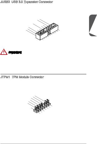
JUSB3: USB 3.0 Expansion
 Connector
The USB 3.0 port is backwards compatible with USB 2.0 devices. It supports data transfer rates up to 5Gbits/s (SuperSpeed).
|
20. |
|||||||||||||||
|
19. |
No |
||||||||||||||
|
18. |
|||||||||||||||
|
16. |
Power |
||||||||||||||
|
15 |
17 |
. |
USB3 |
Pi |
n |
||||||||||
|
13. |
. |
USB3 |
_ |
_ |
|||||||||||
|
USB3Ground |
RX |
||||||||||||||
|
14. |
_ |
RX |
|||||||||||||
|
12. |
USB3 |
_ |
C |
||||||||||||
|
U |
Ground |
TX |
|||||||||||||
|
11. |
USB2 |
_ |
TX_ |
||||||||||||
|
— |
_ |
||||||||||||||
|
SB2. |
C |
||||||||||||||
|
. |
|||||||||||||||
|
0 |
0 |
_ |
|||||||||||||
|
DP |
|||||||||||||||
|
+ |
|
1 |
|||||||||||||||
|
. |
|||||||||||||||
|
. Power |
|||||||||||||||
|
USB3 |
_ |
||||||||||||||
|
USB3 |
_ |
||||||||||||||
|
SB3Ground |
RX |
||||||||||||||
|
USB3 |
_ |
RX |
DN |
||||||||||||
|
TX |
|||||||||||||||
|
. |
Ground |
_ |
|||||||||||||
|
_ |
|||||||||||||||
|
. |
U |
_ TX |
C |
DP |
|||||||||||
|
SB2 |
|||||||||||||||
|
SB2 |
0 |
_ |
_ |
||||||||||||
|
C |
|||||||||||||||
|
Ground |
. |
_ |
|||||||||||||
|
— |
_ |
DN |
|||||||||||||
|
0 |
|||||||||||||||
|
. |
+ |
||||||||||||||
|
DP |
Important
•Note that the VCC and GND pins must be connected correctly to avoid possible damage.
•To use a USB 3.0 device, you must connect the device to a USB 3.0 port through an optional USB 3.0 compliant cable.
JTPM1:
 TPM Module Connector
This connector connects to a TPM (Trusted Platform Module). Please refer to the TPM security platform manual for more details and usages.
|
14. |
||||||||
|
12. |
||||||||
|
6 . |
No Ground |
|||||||
|
4 |
10. |
GroundPi |
||||||
|
. |
5V |
|||||||
|
. |
8 |
|||||||
|
Serial |
||||||||
|
. |
3V |
P n |
||||||
|
ower |
||||||||
|
3 |
||||||||
|
2 . |
IRQ |
|||||||
|
3V |
P |
|||||||
|
Standby |
||||||||
|
ower |
||||||||
|
p |
||||||||
|
ower |
|
13. |
|||||||||||||||||
|
5 |
911 |
. LP |
|||||||||||||||
|
. LP LPC |
C |
||||||||||||||||
|
3 |
7 . |
a |
|||||||||||||||
|
. LP |
a |
Fram |
|||||||||||||||
|
C |
|||||||||||||||||
|
. LP |
a |
ddres |
e |
||||||||||||||
|
LP |
C |
C |
ddres |
s |
|||||||||||||
|
. LP |
a |
||||||||||||||||
|
1 |
|||||||||||||||||
|
C |
ddres |
||||||||||||||||
|
C |
ddres |
s |
& |
||||||||||||||
|
Reset |
& |
||||||||||||||||
|
s |
|||||||||||||||||
|
loc |
s & |
data |
|||||||||||||||
|
k |
& |
p |
|||||||||||||||
|
data |
p |
||||||||||||||||
|
data |
|||||||||||||||||
|
data |
p in2 in3 |
||||||||||||||||
|
p in1 |
|||||||||||||||||
|
in0 |
English
23
English
JBAT1: Clear CMOS Jumper
There is CMOS RAM onboard that is external powered from a battery located on the motherboard to save system configuration data. With the CMOS RAM, the system can automatically boot into the operating system (OS) every time it is turned on. If you want to clear the system configuration, set the jumpers to clear the CMOS RAM.
 Important
You can clear the CMOS RAM by shorting this jumper while the system is off. Afterwards, open the jumper . Do not clear the CMOS RAM while the system is on because it will damage the motherboard.
PCI _E1~3:

 PCIe Expansion
 Slots
Slots
The PCIe slot supports the PCIe interface expansion card.
PCIe x16 Slot
PCIe x1 Slot
 Important
When adding or removing expansion cards, always turn off the power supply and unplug the power supply power cable from the power outlet. Read the expansion card’s documentation to check for any necessary additional hardware or software changes.
24
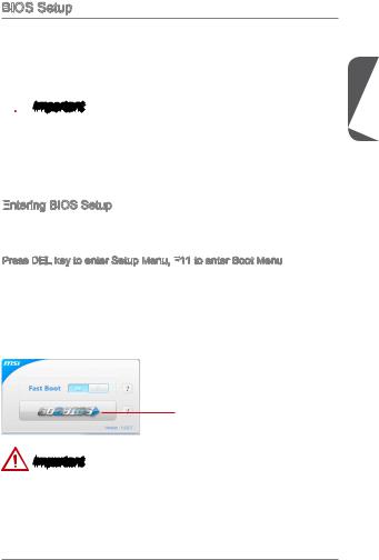
BIOS Setup
The default settings offer the optimal performance for system stability in normal conditions. You may need to run the Setup program when:
■An error message appears on the screen during the system booting up, and requests you to run SETUP.
■You want to change the default settings for customized features.
 Important
•Please load the default settings to restore the optimal system performance and stability if the system becomes unstable after changing BIOS settings. Select the «Restore Defaults» and press <Enter> in BIOS to load the default settings.
•If you are unfamiliar with the BIOS settings, we recommend that you keep the default settings to avoid possible system damage or failure booting due to inappropriate BIOS configuration.
Entering
 BIOS Setup
Power on the computer and the system will start the Power On Self Test (POST) process. When the message below appears on the screen, please <DEL> key to enter BIOS:
Press DEL key to enter Setup Menu, F11
 to enter Boot Menu
If the message disappears before you respond and you still need to enter BIOS, restart the system by turning the computer OFF then back ON or pressing the RESET button. You may also restart the system by simultaneously pressing <Ctrl>, <Alt>, and <Delete> keys.
MSI additionally provides two methods to enter the BIOS setup. You can click the “GO2BIOS” tab on “MSI Fast Boot” utility screen or press the physical “GO2BIOS» button (optional) on the motherboard to enable the system going to BIOS setup directly at next boot.
Click «GO2BIOS» tab on «MSI Fast
Boot» utility screen.
Important
Please be sure to install the “MSI Fast Boot” utility before using it to enter the BIOS setup.
English
25
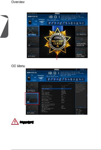
English
Overview
After entering BIOS, the following screen is displayed.
|
Temperature monitor |
Language |
System |
|||||||||||||||||||||
|
Model name |
information |
||||||||||||||||||||||
|
Virtual OC |
|||||||||||||||||||||||
|
Genie Button |
|||||||||||||||||||||||
|
Boot device |
|||||||||||||||||||||||
|
priority bar |
|||||||||||||||||||||||
|
BIOS menu |
|||||||||||||||||||||||
|
selection |
|||||||||||||||||||||||
|
BIOS |
menu |
||||||||||||||||||||||
|
selection |
|||||||||||||||||||||||
Menu display
OC Menu
Important
•Overclocking your PC manually is only recommended for advanced users.
•Overclocking is not guaranteed, and if done improperly, can void your warranty or severely damage your hardware.
•If you are unfamiliar with overclocking, we advise you to use OC Genie for easy overclocking.
26
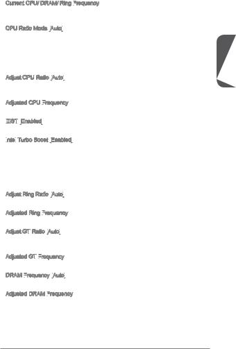
Current CPU/ DRAM/ Ring Frequency

These items show the current frequencies of installed CPU, Memory and Ring. Read-only.
CPU Ratio Mode [Auto]

Selects the CPU Ratio operating mode.
|
[Auto] |
This setting will be configured automatically by BIOS. |
|
[Fixed Mode] |
Fixes the CPU ratio. |
|
[Dynamic Mode] |
CPU ratio will be changed dynamically according to the CPU |
|
loading. |
Adjust CPU Ratio [Auto]

Sets the CPU ratio that is used to determine CPU clock speed. This item can only be changed if the processor supports this function.
Adjusted CPU Frequency

Shows the adjusted CPU frequency. Read-only.
EIST

 [Enabled]

Enables or disables the Enhanced Intel® SpeedStep Technology.
Intel


 Turbo Boost [Enabled]

Enables or disables the Intel® Turbo Boost. This item appears when the installed CPU supports this function.
|
[Enabled] |
Enables this function to boost CPU performance automatically |
|
above rated specifications when system request the highest |
|
|
performance state. |
|
|
[Disabled] |
Disables this function. |
Adjust Ring Ratio [Auto]

Sets the ring ratio. The valid value range depends on the installed CPU.
Adjusted Ring Frequency

Shows the adjusted Ring frequency. Read-only.
Adjust GT Ratio [Auto]

Sets the integrated graphics ratio. The valid value range depends on the installed CPU.
Adjusted GT Frequency

Shows the adjusted integrated graphics frequency. Read-only.
DRAM Frequency
 [Auto]

Sets the DRAM frequency. Please note the overclocking behavior is not guaranteed.
Adjusted DRAM Frequency

Shows the adjusted DRAM frequency. Read-only.
English
27
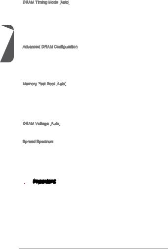
English
DRAM Timing Mode [Auto]


 Selects the memory timing mode.
|
[Auto] |
DRAM timings will be determined based on SPD (Serial Presence |
|
Detect) of installed memory modules. |
|
|
[Link] |
Allows user to configure the DRAM timing manually for all memory |
|
channel. |
|
|
[UnLink] |
Allows user to configure the DRAM timing manually for respective |
|
memory channel. |
Advanced DRAM Configuration
Press <Enter> to enter the sub-menu. This sub-menu will be activated after setting [Link] or [Unlink] in “DRAM Timing Mode”. User can set the memory timing for each memory channel. The system may become unstable or unbootable after changing memory timing. If it occurs, please clear the CMOS data and restore the default settings. (Refer to the Clear CMOS jumper/ button section to clear the CMOS data, and enter the BIOS to load the default settings.)
Memory Fast
 Boot [Auto]


Enables or disables the initiation and training for memory every booting.
|
[Auto] |
This setting will be configured automatically by BIOS. |
|
[Enabled] |
Memory will completely imitate the archive of first initiation and |
|
first training. After that, the memory will not be initialed and trained |
|
|
when booting to accelerate the system booting time. |
|
|
[Disabled] |
The memory will be initialed and trained every booting. |
DRAM Voltage [Auto]


Sets the memory voltage. If set to «Auto», BIOS will set memory voltage automatically or you can set it manually.
Spread Spectrum
This function reduces the EMI (Electromagnetic Interference) generated by modulating clock generator pulses.
|
[Enabled] |
Enables the spread spectrum function to reduce the EMI |
|
(Electromagnetic Interference) problem. |
|
|
[Disabled] |
Enhances the overclocking ability of CPU Base clock. |
 Important
•If you do not have any EMI problem, leave the setting at [Disabled] for optimal system stability and performance. But if you are plagued by EMI, select the value of Spread Spectrum for EMI reduction.
•The greater the Spread Spectrum value is, the greater the EMI is reduced, and the system will become less stable. For the most suitable Spread Spectrum value, please consult your local EMI regulation.
•Remember to disable Spread Spectrum if you are overclocking because even a slight jitter can introduce a temporary boost in clock speed which may just cause your overclocked processor to lock up.
28
CPU Features

Press <Enter> to enter the sub-menu.
Hyper

 -Threading
 Technology [Enabled]


The processor uses Hyper-Threading technology to increase transaction rates and reduces end-user response times. Intel Hyper-Threading technology treats the multi cores inside the processor as multi logical processors that can execute instructions simultaneously. In this way, the system performance is highly improved.
|
[Enable] |
Enables Intel Hyper-Threading technology. |
|
[Disabled] |
Disables this item if the system does not support HT function. |
Active Processor Cores [All]


This item allows you to select the number of active processor cores.
Limit
 CPUID Maximum [Disabled]


Enables or disables the extended CPUID value.
|
[Enabled] |
BIOS will limit the maximum CPUID input value to circumvent |
|
boot problems with older operating system that do not support |
|
|
the processor with extended CPUID value. |
|
|
[Disabled] |
Use the actual maximum CPUID input value. |
Execute
 Disable Bit [Enabled]


Intel’s Execute Disable Bit functionality can prevent certain classes of malicious “buffer overflow” attacks where worms attempt to execute code to damage the system. It is recommended that keeps this item enabled always.
|
[Enabled] |
Enables NO-Execution protection to prevent the malicious |
|
attacks and worms. |
|
|
[Disabled] |
Disables this function. |
Intel


 Virtualization Tech [Enabled]

Enables or disables Intel Virtualization technology.
|
[Enabled] |
Enables Intel Virtualization technology and allows a platform |
|
to run multiple operating systems in independent partitions. |
|
|
The system can function as multiple systems virtually. |
|
|
[Disabled] |
Disables this function. |
Hardware
 Prefetcher [Enabled]


Enables or disables the hardware prefetcher (MLC Streamer prefetcher).
|
[Enabled] |
Allows the hardware prefetcher to automatically pre-fetch |
|
data and instructions into L2 cache from memory for tuning |
|
|
the CPU performance. |
|
|
[Disabled] |
Disables the hardware prefetcher. |
English
29

English
Adjacent Cache Line
 Prefetch [Enabled]


Enables or disables the CPU hardware prefetcher (MLC Spatial prefetcher).
|
[Enabled] |
Enables adjacent cache line prefetching for reducing the |
|
cache latency time and tuning the performance to the specific |
|
|
application. |
|
|
[Disabled] |
Enables the requested cache line only. |
CPU AES Instructions
 [Enabled]


Enables or disables the CPU AES (Advanced Encryption Standard-New Instructions) support. This item appears when a CPU supports this function.
|
[Enabled] |
Enables Intel AES support. |
|
[Disabled] |
Disables Intel AES support. |
Intel


 Adaptive Thermal

 Monitor [Enabled]


Enables or disables the Intel adaptive thermal monitor function to protect the CPU from overheating.
|
[Enabled] |
Throttles down the CPU core clock speed when the CPU is |
|
over the adaptive temperature. |
|
|
[Disabled] |
Disables this function. |
Intel


 C-State [Auto]


C-state is a processor power management technology defined by ACPI.
|
[Auto] |
This setting will be configured automatically by BIOS. |
|
[Enabled] |
Detects the idle state of system and reduce CPU power |
|
consumption accordingly. |
|
|
[Disabled] |
Disable this function. |
C1E Support [Disabled]


Enables or disables the C1E function for power-saving in halt state. This item appears when «Intel C-State» is enabled.
|
[Enabled] |
Enables C1E function to reduce the CPU frequency and |
|
voltage for power-saving in halt state. |
|
|
[Disabled] |
Disables this function. |
Package C State limit

 [Auto]


This item allows you to select a CPU C-state mode for power-saving when system is idle. This item appears when «Intel C-State» is enabled.
|
[Auto] |
This setting will be configured automatically by BIOS. |
|
[C0~C7s] |
The power-saving level from high to low is C7s, C7, C6, C3, |
|
C2, then C0. |
|
|
[No limit] |
No C-state limit for CPU. |
LakeTiny
 Feature
 [Disabled]


Enables or disables Intel Lake Tiny feature with iRST for SSD. This item appears when a installed CPU supports this function and «Intel C-State» is enabled.
|
[Enabled] |
Enhance the dynamic IO load adjusted performance for |
|
accelerating the SSD speed. |
|
|
[Disabled] |
Disables this feature. |
30
![]()
31

English
32

H81M-P33 V2/ H81M-E33 V2/ B85M-P33 V2/ B85M-E33 V2 (MS-7846 v2.X) Micro-ATX . H81M-P33 V2/ H81M-E33 V2/ B85M-P33 V2/ B85M-E33 V2 Intel H81/ B85 . Intel LGA1150H81M-P33 V2/ H81M-E33 V2/ B85M-P33 V2/ B85M-E33 V2.
|
Top : mouse / keyboard |
|
|
Bottom: USB2.0 ports |
CPUFAN |
|
JPWR2 |
|
SYSFAN2 |
|
|
Top : |
|
|
Parallel port (optional) |
|
|
Bottom: |
|
|
DVI-D port (optional) |
JPWR1 |
|
HDMI port (optional) |
|
|
VGA port |
|
|
USB3.0 ports |
|
(optional) |
||||||||||||||||||||||||||
|
Top: LAN Jack |
DIMM1 |
DIMM2 |
||||||||||||||||||||||||
|
Bottom: USB2.0 |
ports |
|||||||||||||||||||||||||
|
T:Line-In |
2 |
|||||||||||||||||||||||||
|
M:Line-Out |
_ |
|||||||||||||||||||||||||
|
B:Mic-In |
SYSFAN1 |
JUSB3 |
||||||||||||||||||||||||
|
PCI_E1 |
||||||||||||||||||||||||||
|
PCI_E2 |
4 |
|||||||||||||||||||||||||
|
SATA3 |
||||||||||||||||||||||||||
|
PCI_E3 |
2 |
|||||||||||||||||||||||||
|
JBAT1 |
JCI1 |
SATA1 |
||||||||||||||||||||||||
|
JFP2 |
||||||||||||||||||||||||||
|
JUSB3_1 (optional) |
||||||||||||||||||||||||||
|
JAUD1 |
JTPM1 |
COM1 |
JUSB2 |
JUSB1 |
JFP1 |
33

|
■ LGA 1150 4 Intel® Core™ i7 / Core™ i5 / |
||
|
CPU |
Core™ i3 / Pentium® / Celeron® . |
|
|
■ Intel® H81/ B85 Express |
||
|
■ DDR3 2 , 16GB |
||
|
■ DDR3 1600/ 1333/ 1066 MHz |
||
|
■ |
||
|
■ non-ECC, un-buffered |
||
|
■ PCIe x16 1 |
||
|
■ PCIe 2.0 x1 2 |
||
|
■ VGA 1 , 1920×1200 @ 60Hz, 24bpp |
||
|
■ HDMI 1 ( ), 4096×2160@24Hz, 24bpp/ |
||
|
2560×1600@60Hz, 24bpp/ 1920×1080@60Hz, 36bpp |
||
|
■ DVI-D 1 ( ), 1920×1200 @ 60Hz, 24bpp |
||
|
■ Intel H81/ B85 Express |
||
|
— SATA 6Gb/s 2 (SATA1~2) |
||
|
— SATA 3Gb/s 2 (SATA3~4) |
||
|
— Intel Rapid Start Technology ( )* |
||
|
— Intel Smart Connect Technology |
||
|
* Windows 7 Windows 8 |
||
|
. |
||
|
USB |
■ Intel H81/ B85 Express |
|
|
— USB 3.0 4 ( 2 , USB |
||
|
2 *) |
||
|
— USB 2.0 8 ( 4 , USB |
||
|
4 ) |
||
|
* H81M-P33 V2/ H81M-E33 V2 USB 3.0 |
||
|
NEC uPD720202 USB 3.0 . |
||
|
■ Realtek® ALC887 |
||
|
LAN |
■ Realtek® RTL8111G Gigabit LAN |
|
|
34 |


 ■ PS/2 / 1■ VGA 1
■1 ( )
■DVI-D 1 ( )
■HDMI 1 ( )
■USB 2.0 4
■USB 3.0 2
■LAN (RJ45) 1
■3
■ 24 ATX 1
■4 ATX 12V 1
■SATA 6Gb/s 2
■SATA 3Gb/s 2
■USB 2.0 2 ( USB 2.0 4 )
■USB 3.0 1 ( USB 3.0 2 )
■4 CPU 1
■4 1
■3 1
■1
■1
■TPM 1
■2
■1
■CMOS 1
BIOS ■ UEFI AMI BIOS
■ACPI 5.0, PnP 1.0a, SM BIOS 2.7, DMI 2.0
■ Micro-ATX
■8.9 in. x 9.0 in. (22.6 cm x 22.8 cm)
CPU
http://www.msi.com/service/cpu-support/ .
http://www.msi.com/service/test-report/ .
35

|
H81M—P33 V2 |
H81M—E33 V2 |
||
|
PCIe x16 |
Gen2 |
Gen2 |
|
|
I/O |
, DVI-D |
HDMI |
|
|
BIOS ROM |
64Mb |
64Mb |
|
|
Small Business |
|||
|
Advantage |
|||
|
Intel Rapid Start |
|||
|
Intel Smart Response |
|||
|
Intel Smart Connect |
|||
|
B85M—P33 V2 |
B85M—E33 V2 |
||
|
PCIe x16 |
Gen3 |
Gen3 |
|
|
I/O |
, DVI-D |
HDMI |
|
|
BIOS ROM |
128Mb |
128Mb |
|
|
Small Business |
|||
|
Advantage |
|||
|
Intel Rapid Start |
|||
|
Intel Smart Response |
|||
|
Intel Smart Connect |
36

|
B85M-P33 V2/ H81M-P33 V2 |
||||
|
PS/2 / |
LAN |
|||
|
USB 3.0 |
||||
|
USB 2.0 |
DVI-D |
VGA |
USB 2.0 |
|
|
B85M-E33 V2/ H81M-E33 V2 |
|
PS/2 / |
LAN |
|||
|
USB 3.0 |
||||
|
HDMI |
||||
|
USB 2.0 |
® |
VGA |
USB 2.0 |
LAN
 LED
LED

|
LINK/ACT |
SPEED |
||
|
LED |
LED |
||
|
LED |
LED |
||
|
LAN |
|||
|
. |
|||
|
Link/ Activity LED |
|||
|
LAN . |
|||
|
( / LED) |
|||
|
LAN |
|||
|
. |
|||
|
Speed LED |
10 Mbps . |
||
|
100 Mbps . |
|||
|
( LED) |
|||
|
1 Gbps . |
|||
37

CPU
CPU , CPU . CPU. CPU. CPU .

CPU .
http://youtu.be/bf5La099urI
|
1. . |
||
|
2. . |
||

CPU .
3.CPU . CPU .
4. 합니다.
CPU
38

5.PnP CPU . PnP. CPU PnP .
6.CPU CPU () .
7.CPU .
8..
9.4 . 4..
10..
11.CPU CPU .
•CPU .
•CPU , CPU.
•CPU / ,/ .
39


1
2
3

•DDR3 DDR2 , DDR3. DDR3 DIMM DDR3 .
•.
40
![]()
JPWR1~2: ATX
ATX
ATX . ATX. .

.
|
12. |
|||||||||||
|
11 |
. +3 |
. |
|||||||||
|
910. |
|||||||||||
|
7 |
. |
+12V |
3 |
||||||||
|
8 |
V |
||||||||||
|
6 . |
|||||||||||
|
5 . |
|||||||||||
|
1 |
4 |
. +5 |
|||||||||
|
3 . |
Ground |
||||||||||
|
2 |
. +5 |
||||||||||
|
+3.Ground |
|||||||||||
|
. |
V |
||||||||||
|
. |
+3. |
||||||||||
|
33V |
|||||||||||
|
V |
|
JPWR1 |
|||
|
+3.Ground |
|||
|
. |
— |
||
|
13. |
— |
ON |
# |
|
12V |
|||
|
3V |
|
24. |
||
|
23. |
||
|
Ground |
||
|
. +5 |
V |
|
|
+5 |
||
|
+5 |
V |
|
|
V |

ATX.
COM1:


16550A 16 FIFO ..
|
1 |
||||||||||
|
0 |
||||||||||
|
8 . |
||||||||||
|
6 |
. N |
|||||||||
|
C |
o |
|||||||||
|
4 |
. |
T |
P |
|||||||
|
D |
S |
i |
||||||||
|
2 |
. |
S |
n |
|||||||
|
D |
R |
|||||||||
|
. |
T |
|||||||||
|
S |
R |
|||||||||
|
I |
||||||||||
|
N |
|
9 |
|||||||||
|
7 |
. |
||||||||
|
R |
|||||||||
|
5 |
. |
I |
|||||||
|
R |
|||||||||
|
3 |
. |
T |
|||||||
|
G |
S |
||||||||
|
1 |
. |
r |
|||||||
|
S |
o |
||||||||
|
. |
O |
u |
|||||||
|
D |
U |
n |
|||||||
|
C |
d |
||||||||
|
T |
|||||||||
|
D |
41

SATA1~4: SATA
SATA
SATA . SATA. SATA (HDD),(SSD) (CD/ DVD/ ) .

SATA HDD.
|
SATA4 |
SATA1~2 (Intel® H81/ |
B85 6Gb/s) |
|
SATA3~4 (Intel® H81/ |
B85 3Gb/s ) |
|
|
SATA3 |
SATA2
SATA1

•(HDD), (SSD) (CD / DVD / ) SATA. .
•HDD, SSD, SATA.SATA .
•SATA 90 ..
•SATA .
JCI1:
. ,.. , BIOS .
|
1 |
||||||
|
2 |
. |
|||||
|
G |
||||||
|
. |
r |
|||||
|
C |
o |
|||||
|
I |
u |
|||||
|
N |
n |
|||||
|
T |
d |
|||||
|
R |
||||||
|
U |
42

CPUFAN,SYSFAN1~2:
+12V .CPU. ., .
 CPUFAN/ SYSFAN1
|
1 |
||
|
2 . |
||
|
+12VGround |
||
|
3 . |
||
|
4 . |
||
|
Sens |
||
|
. |
||
|
Speed |
e |
|
|
C |
||
|
ontrol |
 SYSFAN2
1 . 2 . Ground 3 +12V . No Use

•.
•. CPUCommand Center.
•,.
•, .
JAUD1:

,
Intel® Front Panel I/O Connectivity Design Guide .
|
10. |
||||||
|
4 |
8 |
|||||
|
. NoHead |
||||||
|
6 |
. |
|||||
|
Pi |
P |
|||||
|
. MI |
||||||
|
2 |
NC |
D |
hone |
|||
|
C n |
||||||
|
. |
||||||
|
Ground |
etection |
Detection |
||||
|
9 |
|||||||||
|
3 . |
. |
||||||||
|
Head |
|||||||||
|
7 |
|||||||||
|
5 . |
|||||||||
|
. MIHeadSENSE |
P |
||||||||
|
. |
R |
||||||||
|
1 |
P |
hone |
|||||||
|
MI |
C |
_ |
|||||||
|
L |
SEN |
L |
|||||||
|
C |
hone |
||||||||
|
R |
D |
43

JFP1, JFP2:
LED . JFP1 Intel® Front Panel I/O Connectivity Design Guide .M- . M-M- .

.
|
P |
||||||||
|
P |
ower |
S |
10. |
|||||
|
ower |
LE |
witch |
No |
|||||
|
8Pi |
||||||||
|
D |
6 |
. n |
||||||
|
— |
||||||||
|
4 |
. |
|||||||
|
+ |
||||||||
|
2 |
. |
|||||||
|
— |
||||||||
|
. |
||||||||
|
+ |
JFP1
|
9 |
||||||||||||
|
1 |
. |
|||||||||||
|
7 |
Reserve |
|||||||||||
|
5 |
. |
|||||||||||
|
+ |
||||||||||||
|
3 |
. |
|||||||||||
|
— |
||||||||||||
|
. |
||||||||||||
|
. |
— |
Reset |
d |
|||||||||
|
+ |
||||||||||||
|
HDD |
||||||||||||
|
LE |
S |
|||||||||||
|
D |
witch |
JFP2
|
4 |
|||||
|
1 |
. |
||||
|
3 |
VCC5 |
||||
|
. |
|||||
|
VCC5Speaker |
|||||
|
2 |
|||||
|
. |
|||||
|
. |
|||||
|
Speaker |

•(+) .M-.
•JFP1 .
JUSB1~2: USB 2.0
USB HDD, , MP3 , , USB .
|
1 |
|||||||||||
|
0 |
|||||||||||
|
6 |
8 . |
||||||||||
|
G NC |
|||||||||||
|
. |
. |
r |
|||||||||
|
4 |
|||||||||||
|
U |
o |
||||||||||
|
. |
S |
u |
|||||||||
|
2 |
U |
n |
|||||||||
|
B |
d |
||||||||||
|
. |
S |
1 |
|||||||||
|
V |
B |
+ |
|||||||||
|
C |
1 |
||||||||||
|
C |
— |
|
9 |
|||||||||||
|
7 |
. |
||||||||||
|
N |
|||||||||||
|
5 . |
o |
||||||||||
|
. G |
P |
||||||||||
|
3 |
U |
r |
i |
||||||||
|
o |
n |
||||||||||
|
1 |
. |
S |
u |
||||||||
|
U |
B |
n |
|||||||||
|
. |
S |
||||||||||
|
V |
0 |
d |
|||||||||
|
C |
B |
+ |
|||||||||
|
0 |
|||||||||||
|
C |
— |

VCC GND .
44

JUSB3: USB 3.0
USB 3.0 USB 2.0 . 5Gbits/s (SuperSpeed) .
|
20. |
|||||||||||||||
|
19. |
No |
||||||||||||||
|
18. |
|||||||||||||||
|
16. |
Power |
||||||||||||||
|
15 |
17 |
. |
USB3 |
Pi |
n |
||||||||||
|
13. |
. |
USB3 |
_ |
_ |
|||||||||||
|
USB3Ground |
RX |
||||||||||||||
|
14. |
_ |
RX |
|||||||||||||
|
12. |
USB3 |
_ |
C |
||||||||||||
|
U |
Ground |
TX |
|||||||||||||
|
11. |
USB2 |
_ |
TX_ |
||||||||||||
|
— |
_ |
||||||||||||||
|
SB2. |
C |
||||||||||||||
|
. |
|||||||||||||||
|
0 |
0 |
_ |
|||||||||||||
|
DP |
|||||||||||||||
|
+ |
|
1 |
|||||||||||||||
|
. |
|||||||||||||||
|
. Power |
|||||||||||||||
|
USB3 |
_ |
||||||||||||||
|
USB3 |
_ |
||||||||||||||
|
SB3Ground |
RX |
||||||||||||||
|
USB3 |
_ |
RX |
DN |
||||||||||||
|
TX |
|||||||||||||||
|
. |
Ground |
_ |
|||||||||||||
|
_ |
|||||||||||||||
|
. |
U |
_ TX |
C |
DP |
|||||||||||
|
SB2 |
|||||||||||||||
|
SB2 |
0 |
_ |
_ |
||||||||||||
|
C |
|||||||||||||||
|
Ground |
. |
_ |
|||||||||||||
|
— |
_ |
DN |
|||||||||||||
|
0 |
|||||||||||||||
|
. |
+ |
||||||||||||||
|
DP |
•VCC GND .
•USB 3.0 USB 3.0 USB 3.0.
JTPM1:
 TPM
TPM 


TPM (Trusted Platform Module) .TPM .
|
14. |
||||||||
|
12. |
||||||||
|
6 . |
No Ground |
|||||||
|
4 |
10. |
GroundPi |
||||||
|
. |
5V |
|||||||
|
. |
8 |
|||||||
|
Serial |
||||||||
|
. |
3V |
P n |
||||||
|
ower |
||||||||
|
3 |
||||||||
|
2 . |
IRQ |
|||||||
|
3V |
P |
|||||||
|
Standby |
||||||||
|
ower |
||||||||
|
p |
||||||||
|
ower |
|
13. |
|||||||||||||||||
|
5 |
911 |
. LP |
|||||||||||||||
|
. LP LPC |
C |
||||||||||||||||
|
3 |
7 . |
a |
|||||||||||||||
|
. LP |
a |
Fram |
|||||||||||||||
|
C |
|||||||||||||||||
|
. LP |
a |
ddres |
e |
||||||||||||||
|
LP |
C |
C |
ddres |
s |
|||||||||||||
|
. LP |
a |
||||||||||||||||
|
1 |
|||||||||||||||||
|
C |
ddres |
||||||||||||||||
|
C |
ddres |
s |
& |
||||||||||||||
|
Reset |
& |
||||||||||||||||
|
s |
|||||||||||||||||
|
loc |
s & |
data |
|||||||||||||||
|
k |
& |
p |
|||||||||||||||
|
data |
p |
||||||||||||||||
|
data |
|||||||||||||||||
|
data |
p in2 in3 |
||||||||||||||||
|
p in1 |
|||||||||||||||||
|
in0 |
45

JBAT1: CMOS
CMOS
CMOSRAM . CMOS RAM , OS.CMOS RAM .

CMOS RAM . ,. CMOS RAM ..
PCI _E1~3:

 PCIe
PCIe
PCIe PCIe .
PCIe x16
PCIe x1

세요. .
46

BIOS
. ,.
■SETUP .
■.

|
• BIOS , |
|
|
. BIOS » » |
|
|
<Enter> . |
|
|
• BIOS , . , |
|
|
. |
|
|
POST (Power On Self Test) . |
|
|
, <DEL> . |
|
|
Press DEL key to enter Setup Menu, F11 to enter Boot Menu |
|
|
(DEL , F11 .) |
|
|
BIOS , |
|
|
RESET . <Ctrl>, <Alt> <Delete> |
|
|
. |
|
|
MSI BIOS . «MSI Fast Boot» |
|
|
«GO2BIOS» “GO2BIOS»( ) |
|
|
BIOS . |
|
|
«MSI Fast Boot» |
|
|
«GO2BIOS» . |
|
|
“MSI Fast Boot” BIOS |
|
|
. |
47

BIOS .


Virtual OC
Genie
선순위
BIOS
BIOS
OC 


48

Current CPU/ DRAM/ Ring Frequency

CPU, . ( )
CPU Ratio Mode [Auto]


CPU .
|
[Auto] |
BIOS . |
|
[Fixed Mode] |
CPU . |
|
[Dynamic Mode] |
CPU CPU . |
Adjust CPU Ratio [Auto]


CPU CPU ..
Adjusted CPU Frequency

CPU . ( )
EIST

 [Enabled]


Enhanced Intel® SpeedStep Technology.
Intel


 Turbo Boost [Enabled]


Intel® Turbo Boost .CPU .
[Enabled] ,CPU .
[Disabled] .
Adjust Ring Ratio [Auto]


. CPU.
Adjusted Ring Frequency

.( )
Adjust GT Ratio [Auto]


. CPU .
Adjusted GT Frequency

.( )
DRAM Frequency
 [Auto]


DRAM . ,.
Adjusted DRAM Frequency

DRAM .( )
49

DRAM Timing Mode [Auto]

.
|
[Auto] |
DRAM SPD (Serial Presence |
|
Detect) . |
|
|
[Link] |
DRAM . |
|
[UnLink] |
DRAM . |
Advanced DRAM Configuration
<Enter> . “DRAM ” [Link] [Unlink] .. , CMOS. (CMOS / CMOS BIOS .)
Memory Fast
 Boot [Auto]


.
|
[Auto] |
BIOS . |
|
[Enabled] |
. |
|
, |
|
|
. |
|
|
[Disabled] |
. |
DRAM Voltage [Auto]


. «Auto» BIOS..
Spread Spectrum
EMI (Electromagnetic Interference) .
|
[Enabled] |
EMI (Electromagnetic Interference) |
|
. |
|
|
[Disabled] |
CPU . |

•EMI [ ]. EMI EMI.
•EMI .EMI .
•[ ] .
50
 Loading…

Preface
Copyright Notice
The material in this document is the intellectual property of MICRO-STAR
INTERNATIONAL. We take every care in the preparation of this document, but no
guarantee is given as to the correctness of its contents. Our products are under
continual improvement and we reserve the right to make changes without notice.
Trademarks
All trademarks in this manual are properties of their respective owners.
MSI
®
is registered trademark of Micro-Star Int’l Co.,Ltd.
NVIDIA
®
is registered trademark of NVIDIA Corporation.
ATI
®
is registered trademark of AMD Corporation.
AMD
®
is registered trademarks of AMD Corporation.
Intel
®
is registered trademarks of Intel Corporation.
Windows
®
is registered trademarks of Microsoft Corporation.
AMI
®
is registered trademark of American Megatrends Inc.
Award
®
is a registered trademark of Phoenix Technologies Ltd.
Sound Blaster
®
is registered trademark of Creative Technology Ltd.
Realtek
®
is registered trademark of Realtek Semiconductor Corporation.
JMicron
®
is registered trademark of JMicron Technology Corporation.
Netware
®
is registered trademark of Novell, Inc.
Lucid
®
is trademark of LucidLogix Technologies, Ltd.
VIA
®
is registered trademark of VIA Technologies, Inc.
ASMedia
®
is registered trademark of ASMedia Technology Inc.
iPad, iPhone, and iPod are trademarks of Apple Inc.
Qualcomm Atheros and Killer are trademarks of Qualcomm Atheros Inc.
Revision History
Revision
Revision History
Date
V2.0
First release
203/08
■
■
■
■
■
■
■
■
■
■
■
■
■
■
■
■
■
G52-7846X3
Скачать файл PDF «MSI H81M-E33 Руководство по эксплуатации» (8.8 Mb)
Популярность:
16574 просмотры
Подсчет страниц:
1 страницы
Тип файла:
Размер файла:
8.8 Mb
More products and manuals for Motherboards MSI
| Models | Document Type |
|---|---|
|
B85-G43 GAMING |
User Manual
110 pages |
|
H97M-E35 |
User Manual
184 pages |
|
Z97S SLI PLUS |
User Manual
225 pages |
|
B85I Gaming |
Manual
102 pages |
|
H97 GAMING 3 |
User Manual
112 pages |
|
H97I AC |
Manual
104 pages |
|
A88XM-E35 |
User Manual
186 pages |
|
Z87-G55 |
User Manual
219 pages |
|
A78M-E35 |
User Manual
186 pages |
|
A58-G41 PC Mate |
User Manual
94 pages |
|
H81M-P33 |
User Manual
186 pages |
|
Z97A GAMING 6 |
User Manual
108 pages |
|
Z97 XPOWER AC |
User Manual
118 pages |
|
FM2-A55-G43 series |
User Manual
94 pages |
|
Z97A GAMING 7 |
User Manual
114 pages |
|
Z87 XPOWER |
User Manual
120 pages |
|
B75MA-E31 |
User Manual
30 pages |
|
Z87M GAMING |
User Manual
112 pages |
|
Z87 MPOWER SP |
User Manual
118 pages |
|
H81TI |
User Manual
186 pages |


