Samsung и Cookies
На этом сайте используются файлы cookie. Нажимая ПРИНЯТЬ или продолжая просмотр сайта, вы разрешаете их использование.
Подробнее
Выберите ваш регион или язык.
В настоящий момент товары недоступны для заказа на samsung.com/ru
В настоящий момент товары недоступны для заказа на samsung.com/ru
Страна производства: Южная Корея
Производитель: Samsung Medison
Гарантия: 12 месяцев
Класс: экспертный
Назначение: Абдоминальные исследования, поверхностные органы и системы, ангиология, кардиология, поверхностные органы, скелетно-мышечная система, эндокринология, маммология, гастроэнтерология, урология, ортопедия и травматология, онкология, пульмонология, неврология, педиатрия и неонатология, транскраниальные исследования, трансректальные исследования, трансвагинальные исследования, чреспищеводные исследования, проведение биопсий.
![]()
ENGLISH
Document No. CSD-SMESAR7
Revision 03
Copyright SAMSUNG MEDISON Co., LTD.
Safety Requirements
Classifications:
—Type of protection against electrical shock: Class I
—Degree of protection against electrical shock (Patient connection):Type BF equipment
—Degree of protection against harmful ingress of water: Ordinary equipment
—Degree of safety of application in the presence of a flammable anesthetic material with air or with oxygen or nitrous oxide: Equipment not suitable for use in the presence of a flammable anesthetic mixture with air or with oxygen or nitrous oxide.
—Mode of operation: Continuous operation
Electromechanical safety standards met:
—IEC/EN 60601-1 Medical Electrical Equipment, Part 1General Requirements for Safety.
—IEC/EN 60601-1-1 Safety requirements for medical electrical systems.
—IEC/EN 60601-1-2 Electromagnetic compatibility -Requirements and tests.
—IEC/EN 60601-2-37 Particular requirements for the safety of ultrasonic medical diagnostic and monitoring equipment.
—IEC 61157 Declaration of acoustic output parameters.
—ISO 10993-1 Biological evaluation of medical devices.
—UL 60601-1 Medical Electrical Equipment, Part 1 General Requirements for Safety.
—CSA 22.2, 601.1 Medical Electrical Equipment, Part 1 General Requirements for Safety.

Declarations:
This is CSA symbol for Canada and United States of America
This is manufacturer’s declaration of product compliance
0123 with applicable EEC directive(s) and the European notified body.
This is manufacturer’s declaration of product compliance with applicable EEC directive(s).
This is GMP symbol for Good Manufacturing Practice of
Korea quality system regulation.
Certificate of Excellent Service Quality is to certify that the above company has served customers with excellent services by the Ministry of Knowledge Economy Republic of Korea.

READ THIS FIRST
How to Use Your Manual
This manual addresses the reader who is familiar with ultrasound techniques. Only medical doctors or persons supervised by medical doctors should use this system. Sonography training and clinical procedures are not included here. This manual is not intended to be used as training material for the principles of ultrasound, anatomy, scanning techniques, or applications. You should be familiar with all of these areas before attempting to use this manual or your ultrasound system.
This manual does not include diagnosis results or opinions also, check the measurement reference for each application’s result measurement before the diagnosis.
It is useless to make constant or complex adjustments to the equipment controls. The system has been preset at the factory to produce an optimum image in the majority of patients. User adjustments are not usually required. If the user wishes to change image settings, the variables may be set as desired. Optimal images are obtained with little difficulty.
We are not responsible for errors that occur when the system is run on a user’s PC. Non-Medison product names may be trademarks of their respective owners.
Please keep this user guide close to the product as a reference when using the system.
For safe use of this product, you should read ‘Chapter1. Safety’ and ‘Chapter8. Maintenance’ in this manual, prior to starting to use this system.
DANGER˙ ˙ ˙ ˙ ˙ ˙
Describes precautions necessary to prevent user hazards of great urgency. Ignoring a DANGER warning will risk life-threatening injury.
W˙ A˙ RNIN˙ ˙˙˙ G˙
Used to indicate the presence of a hazard that can cause serious personal injury, or substantial property damage.
CAUTION˙ ˙ ˙ ˙˙ ˙ ˙
Indicates the presence of a hazard that can cause equipment damage.
NOTE˙ ˙ ˙ ˙
A piece of information useful for installing, operating and maintaining a system. Not related to any hazard.

Contents
|
Chapter1. |
General Information |
||
|
1.1 |
Overview ………………………………………………………………………………………. |
1-1 |
|
|
1.2 |
Features and Advantages of SonoAceR7 ……………………………………….. |
1-2 |
|
|
1.3 |
Product Configuration……………………………………………………………………… |
1-3 |
|
|
1.3.1 |
Console………………………………………………………………………………… |
1-3 |
|
|
1.3.2 |
LCD Monitor …………………………………………………………………………. |
1-4 |
|
|
1.3.3 |
Control Panel………………………………………………………………………… |
1-5 |
|
|
1.3.4 |
Probes………………………………………………………………………………….. |
1-5 |
|
|
1.4 |
Specifications………………………………………………………………………………….. |
1-6 |
|
|
Chapter2. |
Safety |
||
|
2.1 |
Overview ………………………………………………………………………………………. |
2-1 |
|
|
2.2 |
Safety – Related Information …………………………………………………………… |
2-2 |
|
|
2.2.1 |
Safety Symbols …………………………………………………………………….. |
2-2 |
|
|
2.2.2 |
LABEL………………………………………………………………………………….. |
2-4 |
|
|
2.3 |
Safety Symbols ………………………………………………………………………………. |
2-5 |
|
|
2.3.1 |
Prevention Electric Shock……………………………………………………… |
2-5 |
|
|
2.3.2 |
ESD ……………………………………………………………………………………… |
2-6 |
|
|
2.3.3 |
EMI ………………………………………………………………………………………. |
2-6 |
|
|
2.3.4 |
EMC …………………………………………………………………………………….. |
2-7 |
|
|
2.4 |
Mechanical Safety…………………………………………………………………………. |
2-12 |
|
|
2.4.1 |
Moving Equipment………………………………………………………………. |
2-12 |
|
|
2.4.2 |
Moving Equipment………………………………………………………………. |
2-13 |
|
|
2.5 |
Biological Safety……………………………………………………………………………. |
2-14 |
|
|
2.5.1 |
Biological Safety………………………………………………………………….. |
2-14 |
|
|
2.6 |
Environmental Protection………………………………………………………………. |
2-25 |
Contents

Contents
|
Chapter3. |
Installing the Product |
||
|
3.1 |
Overview |
………………………………………………………………………………………. |
3-1 |
|
3.2 |
Transportation ………………………………………………………………………………… |
3-3 |
|
|
3.2.1 |
Precautions for Transportation………………………………………… |
3-3 |
|
|
3.2.2 |
Temperature and Humidity …………………………………………….. |
3-3 |
|
|
3.3 |
Unpacking |
………………………………………………………………………………………. |
3-4 |
|
3.3.1 |
Unpacking the Box…………………………………………………………. |
3-4 |
|
|
3.3.2 |
Checking Package contents …………………………………………… |
3-5 |
|
|
3.4 |
Condition of Installation …………………………………………………………………… |
3-6 |
|
|
3.4.1 |
Precautions for Installation ……………………………………………… |
3-6 |
|
|
3.4.2 |
Installation Place…………………………………………………………….. |
3-6 |
|
|
3.5 |
Installation Procedure……………………………………………………………………… |
3-7 |
|
|
3.5.1 |
Installation Safety …………………………………………………………… |
3-7 |
|
|
3.5.2 |
Connecting the Power Cord……………………………………………. |
3-8 |
|
|
3.5.3 |
Connecting the Network Cable……………………………………….. |
3-9 |
|
|
3.5.4 |
Connecting the Probe…………………………………………………….. |
3-9 |
|
|
3.6 |
Starting the Product ………………………………………………………………………. |
3-10 |
|
|
3.7 |
Shutting down the Product…………………………………………………………….. |
3-11 |
|
|
3.7.1 |
Power S/W …………………………………………………………………… |
3-11 |
|
|
3.7.2 |
Power Breaker……………………………………………………………… |
3-11 |
|
|
3.8 |
Connecting the Peripherals……………………………………………………………. |
3-12 |
|
|
3.8.1 |
Internal Peripherals ………………………………………………………. |
3-12 |
|
|
3.8.2 |
External Peripherals……………………………………………………… |
3-12 |
|
|
3.9 |
System Setting ……………………………………………………………………………… |
3-14 |
|
|
3.9.1 |
System-General …………………………………………………………… |
3-14 |
|
|
3.9.2 |
System-Display…………………………………………………………….. |
3-17 |
|
|
3.10 |
Peripherals Setting………………………………………………………………………… |
3-20 |
|
|
3.10.1 |
Peripherals …………………………………………………………………… |
3-20 |
|
|
3.10.2 |
Foot Switch ………………………………………………………………….. |
3-20 |
|
|
3.10.3 |
Set / Exit key Setup………………………………………………………. |
3-20 |
|
|
3.10.4 |
User key Setup …………………………………………………………….. |
3-20 |
|
|
3.10.5 |
Print Setup……………………………………………………………………. |
3-21 |
|
|
3.11 |
System Information……………………………………………………………………….. |
3-22 |
|
|
3.12 |
Setting DICOM ( Optional ) ……………………………………………………………. |
3-23 |
|
|
3.12.1 |
DICOM Configuration …………………………………………………… |
3-23 |
|
|
3.12.2 |
DICOM Send Format……………………………………………………. |
3-24 |
|
|
3.12.3 |
DICOM Compression …………………………………………………… |
3-24 |
|
|
3.12.4 |
Display compensation…………………………………………………… |
3-24 |
Contents

|
3.12.5 |
Add DICOM Service …………………………………………………….. |
3-25 |
|
|
3.12.6DICOM Server Information ………………………………………………….. |
3-26 |
||
|
3.12.7 |
Print Server Information………………………………………………… |
3-27 |
|
|
3.12.8Worklist Information…………………………………………………………….. |
3-29 |
||
|
3.12.9PPS Information………………………………………………………………….. |
3-30 |
||
|
3.12.10 |
SC Information……………………………………………………………… |
3-30 |
|
|
3.12.11 |
Storage SR Information………………………………………………… |
3-31 |
|
|
3.12.12 |
Add DICOM Service …………………………………………………….. |
3-31 |
|
|
3.12.13 |
DICOM Service Delete …………………………………………………. |
3-31 |
|
|
3.12.14 |
DICOM Server Test ……………………………………………………… |
3-31 |
|
|
3.12.15 |
DICOM Management …………………………………………………… |
3-31 |
|
|
3.12.16 |
DICOM Log………………………………………………………………….. |
3-33 |
|
|
3.12.17 |
Utility setting …………………………………………………………………. |
3-34 |
|
|
3.13 |
Option setting………………………………………………………………………………… |
3-37 |
|
|
3.13.1 |
Option ………………………………………………………………………….. |
3-37 |
|
|
3.13.2 |
Auto Calc……………………………………………………………………… |
3-38 |
|
|
3.14 |
Measurement Setup ……………………………………………………………………… |
3-39 |
|
|
3.14.1 |
General setting …………………………………………………………….. |
3-39 |
|
|
3.14.2 |
Packages……………………………………………………………………… |
3-41 |
|
|
3.14.3 |
Report ………………………………………………………………………….. |
3-45 |
|
|
3.14.4 |
Obstetrics Measurement Setup…………………………………….. |
3-48 |
|
|
3.14.5Cardiac Measurement Setup ………………………………………………. |
3-54 |
||
|
3.14.6Vascular Measurement Setup……………………………………………… |
3-55 |
||
|
3.14.7Urology Measurement Setup ………………………………………………. |
3-56 |
||
|
3.14.8Fetal Echo Measurement Setup ………………………………………….. |
3-57 |
Contents

Contents
|
Chpater4. |
Checking the Product |
||
|
4.1 |
Overview |
………………………………………………………………………………………. |
4-1 |
|
4.2 |
Starting the Product ………………………………………………………………………… |
4-2 |
|
|
4.3 |
Monitor |
………………………………………………………………………………………. |
4-3 |
|
4.3.1 |
Monitor Display………………………………………………………………. |
4-3 |
|
|
4.4 |
Control Panel………………………………………………………………………………….. |
4-5 |
|
|
4.4.1 |
Detail Control Panel ……………………………………………………….. |
4-5 |
|
|
4.4.2 |
Soft Menu……………………………………………………………………… |
4-7 |
|
|
4.4.3 |
Keyboards …………………………………………………………………….. |
4-7 |
|
|
4.4.4 |
Adjust of Control Panel …………………………………………………… |
4-8 |
|
|
4.5 |
Checking the Performance ……………………………………………………………… |
4-9 |
|
|
4.5.1 |
Basic Check………………………………………………………………….. |
4-9 |
|
|
4.5.2 |
Detail Check ……………………………………………………………….. |
4-10 |
Contents

Contents
|
Chapter5. |
Product Structure |
|
|
5.1 |
Overview ………………………………………………………………………………………. |
5-1 |
|
5.2 |
System Block Diagram……………………………………………………………………. |
5-3 |
|
5.3 |
Basic Structure of SonoAce R7……………………………………………………….. |
5-4 |
|
5.4 |
PSA ………………………………………………………………………………………. |
5-6 |
|
5.5 |
Beamformer Part…………………………………………………………………………….. |
5-8 |
|
5.6 |
CW Part …………………………………………………………………………………….. |
5-11 |
|
5.7 |
Back End Part …………………………………………………………………………….. |
5-15 |
|
5.8 |
PCI Part …………………………………………………………………………………….. |
5-19 |
|
5.9 |
Motor Control Part…………………………………………………………………………. |
5-20 |
|
5.12 |
PC Mother Board ………………………………………………………………………….. |
5-21 |
|
5.13 |
Software DSC……………………………………………………………………………….. |
5-22 |
|
5.16 |
Control Panel………………………………………………………………………………… |
5-23 |
Contents
![]()
Contents
|
Chapter6. |
Basic Maintenance |
||
|
6.1 |
Overview |
………………………………………………………………………………………. |
6-1 |
|
6.2 |
System Information…………………………………………………………………………. |
6-2 |
|
|
6.3 |
Windows Mode……………………………………………………………………………….. |
6-3 |
|
|
6.3.1 |
Entering Windows Mode ………………………………………………… |
6-3 |
|
|
6.4 |
Upgrade |
. ………………………………………………………………………………….. |
6-4 |
|
6.4.1 |
Software Upgrade ………………………………………………………….. |
6-4 |
|
|
6.4.2 |
Hardware Upgrade…………………………………………………………. |
6-4 |
|
|
6.5 |
Admin mode …………………………………………………………………………………… |
6-5 |
|
|
6.5.1 |
Entering Admin Mode …………………………………………………….. |
6-5 |
|
|
6.5.2 |
Admin Mode Functions…………………………………………………… |
6-6 |
|
|
6.6 |
Adding and Deleting Options…………………………………………………………… |
6-9 |
|
|
6.6.1 |
Option type…………………………………………………………………….. |
6-9 |
|
|
6.6.2 |
Registering Option………………………………………………………… |
6-10 |
|
|
6.6.3 |
Option Delte …………………………………………………………………. |
6-12 |
Contents

Contents
|
Chapter7. |
Troubleshooting |
||
|
7.1 |
Overview |
………………………………………………………………………………………. |
7-1 |
|
7.2 |
Power |
………………………………………………………………………………………. |
7-2 |
|
7.2.1 |
Power Failure…………………………………………………………………. |
7-2 |
|
|
7.2.2 |
Power cannot turned off …………………………………………………. |
7-2 |
|
|
7.2.3 |
Power is automatically turned off…………………………………….. |
7-2 |
|
|
7.3 |
Monitor |
………………………………………………………………………………………. |
7-3 |
|
7.3.1 |
Blank Screen………………………………………………………………….. |
7-3 |
|
|
7.3.2 |
Screen Color Abnormal ………………………………………………….. |
7-3 |
|
|
7.4 |
Error Messages………………………………………………………………………………. |
7-4 |
|
|
7.4.1 |
System hangs after an error during booting…………………….. |
7-4 |
|
|
7.4.2 |
System works even if error occurred……………………………….. |
7-4 |
|
|
7.5 |
Image |
…………………………………………………………………………………….. |
7-5 |
|
7.5.1 |
No BW Mode Image Echo ……………………………………………… |
7-5 |
|
|
7.5.2 |
No BW Mode Image Format…………………………………………… |
7-5 |
|
|
7.5.3 |
Noise Link Rain over the BW Mode Image (Noise) …………. |
7-5 |
|
|
7.5.4 |
PW & CW & Color Doppler, M Mode Trouble …………………. |
7-5 |
Contents

Contents
|
Chapter8. |
Disassembly and Reassembly |
||
|
8.1 |
Overview |
………………………………………………………………………………………. |
8-1 |
|
8.2 |
Body Cover Disassembly and Reassembly …………………………………….. |
8-3 |
|
|
8.2.1 |
Preparations…………………………………………………………………… |
8-3 |
|
|
8.2.2 |
Body Front Cover …………………………………………………………… |
8-3 |
|
|
8.2.3 |
Body Back Cover……………………………………………………………. |
8-3 |
|
|
8.2.4 |
Cover Body Side Right & Left …………………………………………. |
8-4 |
|
|
8.2.5 |
Handle AY……………………………………………………………………… |
8-5 |
|
|
8.3 |
LCD & ARM & SPEAKER Disassembly and Reassembly……………….. |
8-6 |
|
|
8.3.1 |
Preparations…………………………………………………………………… |
8-6 |
|
|
8.3.2 |
LCD……………………………………………………………………………….. |
8-6 |
|
|
8.3.3 |
SPEAKER……………………………………………………………………… |
8-7 |
|
|
8.3.4 |
ARM………………………………………………………………………………. |
8-9 |
|
|
8.4 |
Ultrasound System PCB Part Disassembly and Reassembly ………… |
8-11 |
|
|
8.4.1 |
Preparations…………………………………………………………………. |
8-11 |
|
|
8.4.2 |
PSA ASSY …………………………………………………………………… |
8-11 |
|
|
8.4.3 |
CW Board, MAIN Board ……………………………………………….. |
8-12 |
|
|
8.5 |
PC Part Disassembly and Reassembly …………………………………………. |
8-13 |
|
|
8.5.1 |
Preparations…………………………………………………………………. |
8-13 |
|
|
8.5.2 |
HDD & ODD…………………………………………………………………. |
8-13 |
|
|
8.5.3 |
Rear Board…………………………………………………………………… |
8-14 |
|
|
8.5.4 |
POWER……………………………………………………………………….. |
8-15 |
|
|
8.6 |
User Interface Part Disassembly and Reassembly ………………………… |
8-16 |
|
|
8.6.1 |
Preparations…………………………………………………………………. |
8-16 |
|
|
8.6.2 |
Control Panel ……………………………………………………………….. |
8-16 |
|
|
8.6.3 |
Control Panel Board……………………………………………………… |
8-17 |
|
|
8.6.4 |
Track Ball……………………………………………………………………… |
8-18 |
|
|
8.6.5 |
Alpha-Numeric Keyboard……………………………………………… |
8-19 |
|
|
8.6.6 |
LCDIF CON Board……………………………………………………….. |
8-20 |
Contents

Contents
|
Chapter9. |
Probe |
||
|
9.1 |
Overview |
………………………………………………………………………………………. |
9-1 |
|
9.2 |
Probe List |
………………………………………………………………………………………. |
9-2 |
|
9.2.1 |
Probe Application and Preset …………………………………………. |
9-2 |
|
|
9.2.2 |
Function List…………………………………………………………………… |
9-3 |
|
|
9.3 |
Thermal Index (TI Table)……………………………………………………………….. |
9-5 |
|
|
9.4 |
Ultrasound Transmission Gel ………………………………………………………….. |
9-6 |
|
|
9.5 |
Sheaths |
………………………………………………………………………………………. |
9-7 |
|
9.6 |
Probe Precautions ………………………………………………………………………….. |
9-8 |
|
|
9.6.1 |
Use and Infection Control of the Probe……………………………. |
9-8 |
|
|
9.6.2 |
Electric Shocks ………………………………………………………………. |
9-9 |
|
|
9.7 |
Cleaning and Disinfecting the Probe ……………………………………………… |
9-10 |
9.7.1Information of Detergent, Disinfectant and Ultrasound Gel9-10
|
9.7.2 |
Cleaning ………………………………………………………………………. |
9-16 |
|
|
Chapter10. |
User Maintenance |
||
|
10.1 |
Overview |
…………………………………………………………………………………….. |
10-1 |
|
10.2 |
System Maintenance…………………………………………………………………….. |
10-2 |
|
|
10.2.1 |
Installation Maintenance……………………………………………….. |
10-2 |
|
|
10.2.2 |
Cleaning and Disinfections……………………………………………. |
10-2 |
|
|
10.2.3 |
Fuse Replacement……………………………………………………….. |
10-3 |
|
|
10.2.4 |
Administration of Air Filter……………………………………………. |
10-4 |
|
|
10.2.4 |
Accuracy Check………………………………………………………….. |
10-5 |
|
|
10.3 |
Administration of Information …………………………………………………………. |
10-6 |
|
|
10.3.1 |
User Setting Back-up……………………………………………………. |
10-6 |
|
|
10.3.2 |
Patient Information Restore………………………………………… |
10-6 |
|
|
10.3.3 |
Software ………………………………………………………………………. |
10-6 |
|
|
Chapter11. |
Service Part List |
||
|
11.1 |
Overview |
…………………………………………………………………………………….. |
11-1 |
|
11.2 |
Body Cover …………………………………………………………………………………… |
11-2 |
|
|
11.3 |
Ultrasound System Part ………………………………………………………………. |
11-4 |
|
|
11.4 |
LCD & HINGE Part ……………………………………………………………………….. |
11-5 |
|
|
11.5 |
User Interface Part………………………………………………………………………… |
11-6 |
|
|
11.6 |
PC & Power Part…………………………………………………………………………… |
11-8 |
|
|
11.7 |
ETC Part |
…………………………………………………………………………………….. |
11-9 |
|
11.8 |
Options |
………………………………………………………………………………….. |
11-12 |
|
11.9 |
Probes |
………………………………………………………………………………….. |
11-13 |
Contents

Chapter 1. General Information
1.1Overview
Chapter 1 contains the information necessary to plan the Troubleshooting of SonoAceR7.
The SonoAceR7 is a high-resolution color ultrasound scanner with high penetration and a variety of measurement functions.
Contents
|
1.1 |
Overview |
………………………………………………………………………………………… |
1-1 |
|
1.2 |
Features and …………………………………………Advantages of SonoAceR7 |
1-2 |
|
|
1.3 |
Product Configuration……………………………………………………………………… |
1-3 |
|
|
1.3.1 …………………………………………………………………………. |
Console |
1-3 |
|
|
1.3.2 …………………………………………………………………… |
LCD Monitor |
1-4 |
|
|
1.3.3 …………………………………………………………………. |
Control Panel |
1-5 |
|
|
1.3.4 …………………………………………………………………………… |
Probes |
1-5 |
|
|
1.4 |
Specifications………………………………………………………………………………….. |
1-6 |
Chapter 1. General Information 1-1

1.2Features and Advantages of SonoAceR7
High-end Digital Beam forming : The SonoAceR7 utilizes the newly developed Digital Beam forming technology.
A variety of applications : The SonoAceR7 is optimized for use in a variety of ultrasound departments, cardiac, vascular, abdomen, Obstetrics, Urology, Gynecology.
Various diagnostic Modes : 2D Mode, M Mode, Color Doppler Mode, Power Doppler Mode, PW Spectral Doppler Mode, etc.
Measurement and Report Functions : Besides the basic distance, area, circumference and volume measurement functions, the SonoAceR7 also provides application-specific measurement functions. The report function collates measurement data.
Review of Scanned Images : The SonoAceR7 displays Cine images of 7084 frames and loop images of 8192 lines.
SonoView TM : This is a total ultrasound image management system, which allows a user to archive, view and exchange documents.
Digital Imaging and Communication in Medicine (DICOM) Function : This is used to archive, transmit and print DICOM images through a network.
Peripheral/Accessory Connection : A variety of peripheral devices including VCRs and printers can be easily connected to the SonoAceR7.
Chapter 1. General Information 1-2
1.3Product Configuration
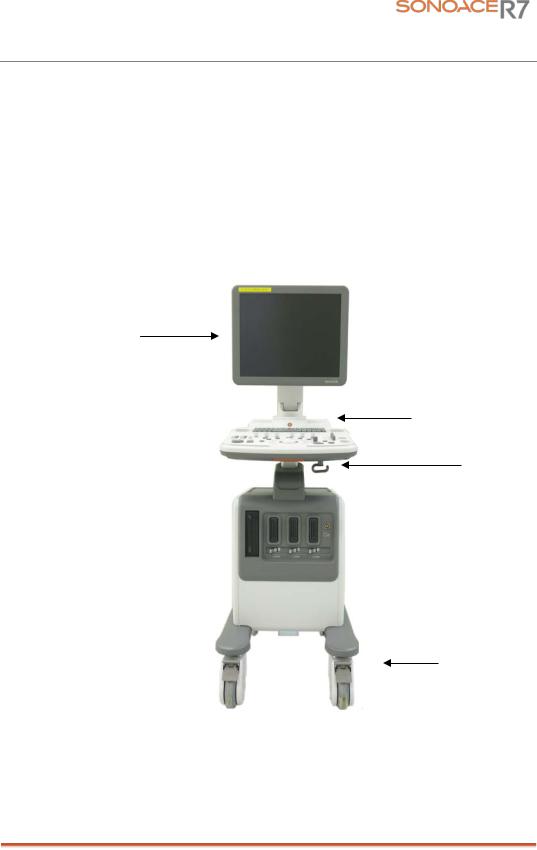
This Product consists of the monitor, the control panel, the console and, the probes.
1.3.1Console
The console consists of two parts – the inner unit and the outer unit.
The interior of the console mainly contains devices that produce ultrasound images.
The outside of the console consists of various connection ports, probe holder, storage space, wheel and handles.
LCD Monitor
Handle
Probe holder
Wheel
[Figure 1-1] Console of SonoAce R7
Chapter 1. General Information 1-3
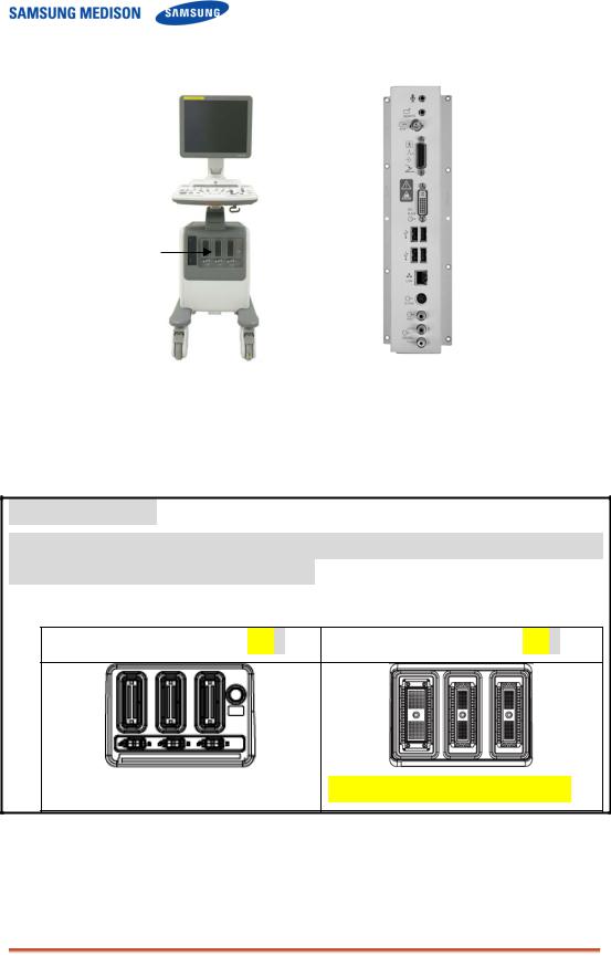
Probe Connector
[Figure 1-2] Front and Back of SonoAce R7
Type of Probe port
Mini DLP type of probe is used for SonoAce R7 v2.00.00. In lower version of product, the shape of the probe port can be different.
|
<v2.xx.xx: Mini DLP Type |
PSA> |
<v1.xx.xx :156 Pin Type |
PSA> |
||||
256 Pin is necessary for 3D probe.
Chapter 1. General Information 1-4
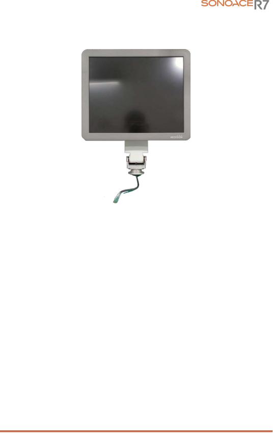
1.3.2LCD Monitor
The monitor of this system is a color VGA monitor, which displays ultrasound images and additional information. Monitor arm can control to be tilted to the optimal viewing angle.
[Figure 1-3] LCD Monitor
Chapter 1. General Information 1-5

1.3.3Control Panel
The control panel can be used for controlling the system.
Alpha-Numeric
Button
Dial Button
Track Ball
Slide Volume
[Figure 1-4] Control Panel
1.3.4Probe
Probes are devices that generate ultrasound waves and process reflected wave data for the purpose of image formation.
NOT˙ ˙ ˙E˙
For more information, refer to ‘Chapter 9. Probes’.
Chapter 1. General Information 1-6
![]()
1.4 Specifications
|
Height: 1340mm (with handle) |
|||
|
Physical Dimensions |
Width: 450mm |
||
|
Depth: 700mm |
|||
|
Weight: More than 61kg (With monitor) |
|||
|
2D imaging mode |
|||
|
M imaging mode |
|||
|
Color Doppler Imaging (CDI) mode |
|||
|
Power Doppler Imaging (PDI) mode |
|||
|
Directional Power Doppler Imaging (DPDI) mode |
|||
|
Imaging modes |
Pulse Wave (PW) Spectral Doppler imaging mode |
||
|
Continuous Wave (CW) Spectral Doppler imaging mode |
|||
|
Tissue Doppler Imaging (TDI) mode |
|||
|
3D imaging mode |
|||
|
Dual modes |
|||
|
Combined modes |
|||
|
Simultaneous mode |
|||
|
Zoom |
|||
|
Gray Scale |
256 (8 bits) |
||
|
Transmit focusing, maximum of eight points (four points |
|||
|
Focusing |
simultaneously selectable) |
||
|
Digital dynamic receive focusing (continuous) |
|||
|
Curved Linear Array : C2-8 |
|||
|
Linear Array : HL5-12ED, L3-8, L5-12/50EP |
|||
|
Probes |
Endocavity Curved Linear Array : ER4-9/10ED, EV4-9/10ED |
||
|
Phased Array : P2-4AH |
|||
|
Volume Probe : 3D4-8ET, 3DC2-6 |
|||
|
Probe connections |
3 probe connectors |
||
|
Monitor |
19 inch LCD monitor |
||
|
VHS and SVHS VCR left and right audio |
|||
|
Rear Panel |
B/W printer video and remote control |
||
|
VGA monitor |
|||
|
Input/Output |
|||
|
Parallel port |
|||
|
Connections |
|||
|
USB |
|||
|
LAN |
|||
|
Maximum 7084 frames for CINE memory |
|||
|
Image Storage |
Maximum 8192 Lines for LOOP memory |
||
|
Image filing system |
|||
|
Application |
Obstetrics, Gynecology, Abdomen, Cardiac, Urology, Vascular, |
||
|
Small Parts, Musculoskeletal, TCD |
|||
|
Chapter 1. General Information 1-7 |

|
Electrical Parameters |
100-120V/200-240V, 250VA, 50/60Hz |
|
|
Automatic Calculation |
Obstetrics, Gynecology, Cardiac, Carotid, Fetal Echo, UE |
|
|
Artery, LE Artery, UE Vein, LE Vein, Urology, Radiology, TCD, |
||
|
and Quantification |
Thyroid, Breast, Testicle, Superficial, Pediatric Hips, MSK |
|
|
* Refer the Chapter 5 for additional information |
||
|
TGC control |
||
|
Mode-independent gain control |
||
|
Acoustic power control (adjustable) |
||
|
Signal processing |
Dynamic aperture |
|
|
(Pre-processing) |
Dynamic apodization |
|
|
Dynamic range control (adjustable) |
||
|
Image view area control |
||
|
M-mode sweep speed control |
||
|
Frame average |
||
|
Signal processing |
Edge Enhancement / Blurring |
|
|
Gamma-scale windowing |
||
|
(Post-processing) |
Image orientation (left/right and up/down, rotation) |
|
|
White on black/black on white |
||
|
Zoom |
||
|
Trackball operation of multiple cursors |
||
|
2D mode: Linear measurements and area measurements using |
||
|
Measurement |
elliptical approximation or trace |
|
|
M mode: Continuous readout of distance, time, and slope rate |
||
|
Doppler mode: Velocity and trace |
||
|
VCR |
||
|
Video Page Printer |
||
|
Color Video Page Printer |
||
|
USB Video Printer |
||
|
Auxiliary |
USB Color Video Printer |
|
|
USB HDD |
||
|
USB Wireless LAN |
||
|
USB Foot Switch |
||
|
USB Flash Memory Media |
||
|
Monitor |
||
|
Microphone |
||
|
User Interface |
English, German, French, Spanish, Italian |
|
|
Pressure Limits |
Operating: 700hPa to 1060hPa |
|
|
Storage: 700hPa to 1060hPa |
||
|
Humidity Limits |
Operating: 30% to 75% |
|
|
Storage & Shipping: 20% to 90% |
||
|
Temperature Limits |
Operating: 10 OC ~ 35OC |
|
|
Storage & Shipping: -25OC ~ 60OC |
Chapter 1. General Information 1-8

Chapter 2. Safety
2.1Overview
Chapter2. contains the information necessary to Safety.
Please read this chapter before using the SAMSUNG MEDISON ultrasound system. It is relevant to the ultrasound system, the probes, the recording devices, and any of the optional equipment.
SonoAce R7 is intended for use by or by the order of, and under the supervision of a licensed physician who is directly qualified to use the medical device.
Contents
|
2.1 |
Overview |
………………………………………………………………………………………… |
2-1 |
|
2.2 |
Safety – Related ……………………………………………………………Information |
2-2 |
|
|
2.2.1 ………………………………………………………………. |
Safety Symbols |
2-2 |
|
|
2.2.2 …………………………………………………………………………… |
LABEL |
2-4 |
|
|
2.3 |
Electrical ……………………………………………………………………………….Safety |
2-5 |
|
|
2.3.1 ………………………………………………. |
Prevention Electric Shock |
2-5 |
|
|
2.3.2 ………………………………………………………………………………. |
ECG |
2-6 |
|
|
2.3.3 ……………………………………………………………………………….. |
ESD |
2-6 |
|
|
2.3.4 ………………………………………………………………………………… |
EMI |
2-6 |
|
|
2.3.5 ………………………………………………………………………………. |
EMC |
2-7 |
|
|
2.4 |
Mechanical ………………………………………………………………………….Safety |
2-12 |
|
|
2.4.1 ……………………………………………………….. |
Moving Equipment |
2-12 |
|
|
2.4.2 ………………………………………………………………….. |
Safety Note |
2-13 |
|
|
2.5 |
Biological …………………………………………………………………………….Safety |
2-14 |
|
|
2.5.1 …………………………………………………………… |
ALARA Principle |
2-14 |
|
|
2.6 |
Environmental ……………………………………………………………….Protection |
2-26 |
Chapter 2. Safety 2-1
2.2Safety – Related Information
2.2.1Safety Symbols
The International Electro Technical Commission (IEC) has established a set of
symbols for medical electronic equipment, which classifies a connection or warn of potential hazards. The classifications and symbols are shown below.
|
Symbols |
Description |
|
|
Isolated patient connection(Type BF applied part) |
||
|
Power switch (Supplies/cuts the power for product). |
||
|
Indicates a caution for risk of electric shock. |
||
|
Indicates dangerous voltages over 1000V AC or over |
||
|
1500V DC. |
||
|
Warning, Caution |
||
|
AC (alternating current) voltage source |
||
|
Print remote output |
||
|
Electrostatic discharge |
||
|
Network port |
||
|
Output port ( DVI, RGB, B/W, S-VHS, SOUND ) |
||
|
Protection against the effects of immersion. |
||
|
Protection against dripping water. |
||
|
Probe connector |
||
|
Consult Instructions for Use |
||
|
Mic port |
||
|
Chapter 2. Safety 2-2 |
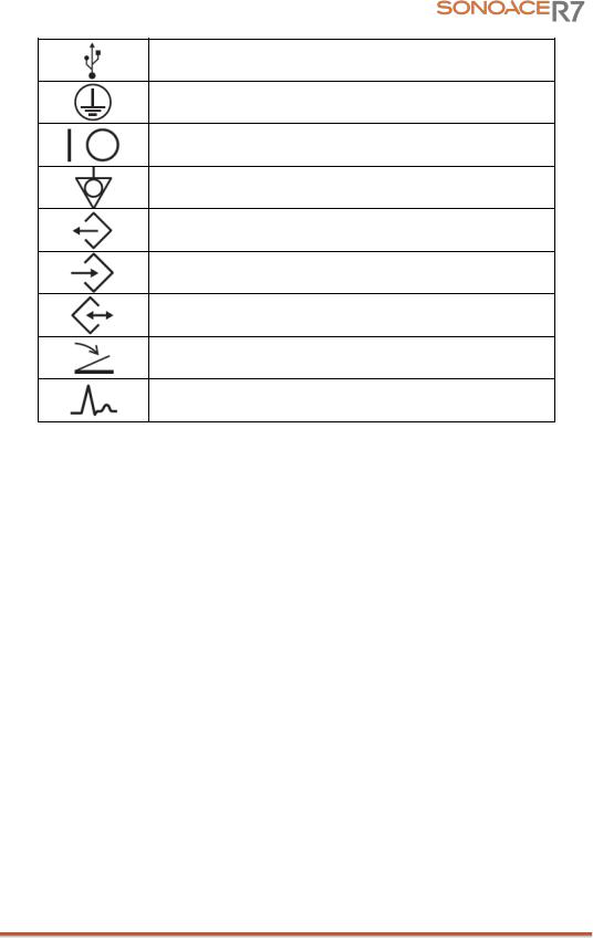
USB port
Power switch (Supplies/cuts the power for product)
Power switch (Supplies/cuts power to the product)
Identifies an equipotential ground.
Data Output port
Data Input port
Data Input/Output port
Foot switch connector
ECG connector
Chapter 2. Safety 2-3

2.2.2LABEL
To protect the system, you may see ‘Warning’ or ‘Caution’ marked on the surface of the product
[ Figure 2-1. Marked on the back sides of the product]
[ Figure 2-2. Marked below OUTLET ]
[ Figure 2-3. Prohibition of seating on Control panel ]
Chapter 2. Safety 2-4
2.3Electrical Safety
This equipment has been verified as a Class I device with Type BF applied parts.
2.3.1Prevention of Electric Shock
In a hospital, dangerous currents are due to the potential differences between connected equipment and touchable conducting parts found in medical rooms. The solution to the problem is consistent equip potential bonding. Medical equipment is connected with connecting leads made up of angled sockets to the equip potential bonding network in medical rooms.
[Figure 2-4] Equip potential bonding
Additional equipment connected to medical electrical equipment must comply with the respective IEC or ISO standards (e.g. IEC 60950 for data processing equipment). Furthermore all configurations shall comply with the requirements for medical electrical systems (see IEC 60601-1-1 or clause 16 of the
 WARNING˙ ˙ ˙ ˙ ˙ ˙ ˙
Electric shock may exist result if this system, including and all of its externally mounted recording and monitoring devices, is not properly grounded.
Do not remove the covers on the system; hazardous voltages are present inside. Cabinet panels
must be in place while the system is in use. All internal adjustments and replacements must be made by a qualified MEDISON Customer Service Department.
Check the face, housing, and cable before use. Do not use, if the face is cracked, chipped, or torn, the housing is damaged, or if the cable is abraded.
Always disconnect the system from the wall outlet prior to cleaning the system.
All patient contact devices, such as probes and ECG leads, must be removed from the patient prior to application of a high voltage defibrillation pulse.
The use of flammable anesthetic gas or oxidizing gases (N20) should be avoided.
 CAUTION˙ ˙ ˙ ˙˙ ˙ ˙
The system has been designed for 100-120VAC and 200-240VAC; you should select the input Outlet voltage of monitor, printer and VCR. Prior to connecting an OEM power cord, verify that the voltage indicated on the power cord matches the voltage rating of the OEM device.
An isolation transformer protects the system from power surges. The isolation transformer continues to operate when the system is in standby.
Do not immerse the cable in liquids. Cables are not waterproof.
The operator does not contact the parts (SIP/SOP) and the patient simultaneously.
Chapter 2. Safety 2-5

2.3.2ECG-Related Information
 WARNING˙ ˙ ˙ ˙ ˙ ˙ ˙
This device is not intended to provide a primary ECG monitoring function, and therefore does not have means of indicating an inoperative electrocardiograph.
Do not use ECG electrodes of HF surgical equipment. Any malfunctions in the HF surgical equipment may result in burns to the patient
Do not use ECG electrodes during cardiac pacemaker procedures or other electrical stimulators.
Do not use ECG leads and electrodes in an operating room.
2.3.3ESD
Electrostatic discharge (ESD), commonly referred to as a static shock, is a naturally occurring phenomenon. ESD is most prevalent during conditions of low humidity, which can be caused by heating or air conditioning. During low humidity conditions, electrical charges naturally build up on individuals, creating static electricity. An ESD occurs when an individual with an electrical energy build-up comes in contact with conductive objects such as metal doorknobs, file cabinets, computer equipment, and even other individuals.
 CAUTION˙ ˙ ˙ ˙˙ ˙ ˙
The level of electrical energy discharged from a system user or patient to an ultrasound system can be significant enough to cause damage to the system or probes.
Always perform the pre-ESD preventive procedures before using connectors marked with the ESD warning label.
—Apply anti-static spray on carpets or linoleum.
—Use anti-static mats.
—Ground the product to the patient table or bed.
It is highly recommended that the user be given training on ESD-related warning symbols and preventive procedures.
2.3.4EMI
Although this system has been manufactured in compliance with existing EMI
(Electromagnetic Interference) requirements, use of this system in the presence of an electromagnetic field can cause momentary degradation of the ultrasound image.
If this occurs often, SAMSUNGMEDISON suggests a review of the environment in which the system is being used, to identify possible sources of radiated emissions. These emissions could be from other electrical devices used within the same room or an adjacent room. Communication devices such as cellular phones and pagers can cause these emissions. The existence of radios, TVs, or microwave transmission equipment nearby can also cause interference.
 CAUTION˙ ˙ ˙ ˙˙ ˙ ˙
In cases where EMI is causing disturbances, it may be necessary to relocate this system.
Chapter 2. Safety 2-6

2.3.5EMC
The testing for EMC(Electromagnetic Compatibility) of this system has been performed according to the international standard for EMC with medical devices (IEC60601-1-2). This IEC standard was adopted in Europe as the European norm (EN60601-1-2).
2.3.5.1Guidance and manufacturer’s declaration — electromagnetic emission
This product is intended for use in the electromagnetic environment specified below.
The customer or the user of this product should assure that it is used in such an environment.
|
Emission test |
Compliance |
Electromagnetic environment -guidance |
||||||
|
The Ultrasound System uses RF energy only |
||||||||
|
RF Emission |
for its internal function. Therefore, its RF |
|||||||
|
Group 1 |
emissions are very low and are not likely to |
|||||||
|
CISPR 11 |
||||||||
|
cause any interference in nearby electronic |
||||||||
|
equipment. |
||||||||
|
RF Emission |
Class B |
|||||||
|
CISPR 11 |
The Ultrasound System is suitable for use in all |
|||||||
|
establishments, including domestic |
||||||||
|
Harmonic Emission |
||||||||
|
Class A |
establishments and those directly connected to |
|||||||
|
IEC 61000-3-2 |
the public low-voltage power supply network |
|||||||
|
that supplies building used for domestic |
||||||||
|
Flicker Emission |
Complies |
purpose. |
||||||
|
IEC 61000-3-3 |
||||||||
2.3.5.2Approved Cables, Transducers and Accessories for EMC
1)Approved Cable for Electromagnetic Compliance
Cables connected to this product may affect its emissions;
Use only the cable types and lengths listed below table.
|
Cable |
Type |
Length |
||||||
|
VGA |
Shielded |
Normal |
||||||
|
Parallel |
Shielded |
Normal |
||||||
|
RS232C |
Shielded |
Normal |
||||||
|
USB |
Shielded |
Normal |
||||||
|
LAN(RJ45) |
Twisted pair |
Any |
||||||
|
S-Video |
Shielded |
Normal |
||||||
|
Foot Switch |
Shielded |
2.5m |
||||||
|
B/W Printer |
Unshielded Coaxial |
Normal |
||||||
|
MIC |
Unshielded |
Any |
||||||
|
Printer Remote |
Unshielded |
Any |
||||||
|
Audio R.L |
Shielded |
Normal |
||||||
|
VHS |
Shielded |
Normal |
||||||
|
ECG AUX input |
Shielded |
< 3m |
2) Approved Transducer for Electromagnetic Compliance
The probe listed in ‘Chapter 9. Probes’ when used with this product, have been tested to comply with the group1 class B emission as required by International Standard CISPR 11.
Chapter 2. Safety 2-7

3) Approved Accessories for Electromagnetic Compliance Accessories used with this product may effect its emissions
 CAUTION˙ ˙ ˙ ˙˙ ˙ ˙
When connecting other customer-supplied accessories to the system, such as a remote printer or VCR, it is the user’s responsibility to ensure the electromagnetic compatibility of the system. Use only CISPR 11 or CISPR 22, CLASS B compliant
devices
 WARNING˙ ˙ ˙ ˙ ˙ ˙ ˙
The use of cables, transducers, and accessories other than those specified may result increased emission or decreased Immunity of the Ultrasound System.
|
Immunity test |
IEC 60601 |
Compliance level |
Electromagnetic environment – |
||||||||||
|
Test level |
guidance |
||||||||||||
|
Electrostatic |
±6KV Contact |
±6KV |
Contact |
Floors should be wood, concrete |
|||||||||
|
or ceramic tile. If floors are |
|||||||||||||
|
discharge (ESD) |
covered with synthetic material, |
||||||||||||
|
IEC 61000-4-2 |
±8KV |
air |
±8KV |
air |
the relative humidity should be at |
||||||||
|
least 30%. |
|||||||||||||
|
Electrical fast |
±2KV |
for power supply |
±2KV for power |
Mains power quality should be that |
|||||||||
|
of a typical commercial or hospital |
|||||||||||||
|
transient/burst |
lines |
supply lines |
|||||||||||
|
environment. |
|||||||||||||
|
±1KV for input/output |
±1KV for input/ |
||||||||||||
|
IEC 61000-4-4 |
lines |
output lines |
|||||||||||
|
Surge |
±1KV differential mode |
±1KV differential mode |
Mains power quality should be that |
||||||||||
|
IEC 61000-4-5 |
±2KV common mode |
±2KV common mode |
of a typical commercial or hospital |
||||||||||
|
environment. |
|||||||||||||
|
Voltage dips, short |
<5% Uт |
<5% Uт |
Mains power quality should be that |
||||||||||
|
interruptions and |
(>95% dip in Uт) |
(>95% dip in Uт) |
of a typical commercial or hospital |
||||||||||
|
voltage variations |
for 0.5cycle |
for 0.5cycle |
environment. If the user of this |
||||||||||
|
on power supply |
product requires continued |
||||||||||||
|
input lines |
40% Uт |
40% Uт |
operation during power mains |
||||||||||
|
(60% dip in Uт ) |
(60% dip in Uт ) |
interruptions, it is recommended |
|||||||||||
|
IEC 61000-4-11 |
for 5 cycle |
for 5 cycle |
that this product be powered from |
||||||||||
|
an uninterruptible power supply or |
|||||||||||||
|
70% Uт |
70% Uт |
a battery. |
|||||||||||
|
(30% dip in Uт) |
(30% dip in Uт) |
||||||||||||
|
for 25 cycle |
for 25 cycle |
||||||||||||
|
<5% Uт |
<5% Uт |
||||||||||||
|
(<95% dip in Uт ) |
(<95% dip in Uт ) |
||||||||||||
|
for 5 s |
for 5 s |
||||||||||||
|
Power frequency |
Power frequency magnetic fields |
||||||||||||
|
(50/60Hz) |
should be at levels characteristic |
||||||||||||
|
magnetic field |
3 A/m |
3 A/m |
of a typical location in a typical |
||||||||||
|
commercial or hospital |
|||||||||||||
|
IEC 61000-4-8 |
environment. |
Chapter 2. Safety 2-8
![]()
NOTE Uт is the a.c. mains voltage prior to application of the test level.
|
Conducted RF |
3 Vrms |
0.01V |
Portable and mobile RF communications |
|
IEC 61000-4-6 |
150 kHz to 80MHz |
equipment should be used no closer to any part |
|
|
of the Ultrasound System, including cables, |
|||
|
than the recommended separation distance |
|||
|
calculated from the equation applicable to the |
|||
|
frequency of the transmitter. |
|||
|
Recommended separation distance |
|
80MHz to 800MHZ |
|||
|
800MHz to 2.5GHz |
|||
|
Radiated RF |
3 V/m |
3 V/m |
Where P is the maximum output power rating of |
|
IEC 61000-4-3 |
80 MHz to 2.5GHz |
the transmitter in watts (W) according to the |
|
|
transmitter manufacturer and d is the |
|||
|
recommended separation distance in meters |
|||
|
(m). |
|||
|
Field strengths from fixed RF transmitters, as |
|||
|
deter-mined by an electromagnetic site survey, a |
|||
|
should be less than the compliance level in |
|||
|
each frequency range. b |
Interference may occur in the vicinity of equipment marked with the following symbol :
NOTE 1) At 80MHz and 800MHz, the higher frequency range applies.
NOTE 2) These guidelines may not apply in all situations. Electromagnetic propagation is affected by absorption and reflection from structures, objects and people.
a Field strengths from fixed transmitters, such as base stations for radio (cellular/cordless) telephones and land mobile radios, amateur radio, AM and FM radio broadcast and TV broadcast cannot be predicted theoretically with accuracy. To assess the electromagnetic environment due to fixed RF transmitters, an electromagnetic site survey should be considered. If the measured field strength in the location in which the Ultrasound System is used exceeds the applicable RF compliance level above, the Ultrasound System should be observed to verify normal operation. If abnormal performance is observed, additional measures may be necessary, such as re-orienting or relocating the Ultrasound System or using a shielded location with a higher RF shielding effectiveness and filter attenuation.
b Over the frequency range 150kHz to 80MHz, field strengths should be less than [V1] V/m.
Chapter 2. Safety 2-9

2.3.5.3Recommended separation distances between portable and mobile RF communications equipment and the SonoAce R7
This product is intended for use in an electromagnetic environment in which radiated RF disturbances are controlled. The customer or the user of this product can help Prevent electromagnetic interference by maintaining a minimum distance between portable and mobile RF communications equipment (transmitters) and this product as recommended below, according to the maximum output power of the communications equipment.
|
Separation distance according to frequency of transmitter [m] |
||||
|
Rated maximum |
150kHz to 80MHz |
80MHz to 800MHz |
800MHz to |
|
|
2.5GHz |
||||
|
output power of |
||||
|
transmitter |
||||
|
[W] |
||||
|
V1=0.01Vrms |
E1=3 V/m |
E1=3V/m |
||
|
0.01 |
35.00 |
0.11 |
0.23 |
|
|
0.1 |
110.68 |
0.36 |
0.73 |
|
|
1 |
350.00 |
1.16 |
2.33 |
|
|
10 |
1106.80 |
3.68 |
7.37 |
|
|
100 |
3500.00 |
11.66 |
23.33 |
|
For transmitters rated at a maximum output power not listed above, the recommended separation distance d in meters (m) can be estimated using the equation applicable to the frequency of the transmitter, where p is the maximum output power rating of the transmitter in watts (W) according to the transmitter manufacturer.
NOTE 1) At 80MHz and 800MHz, the separation distance for the higher frequency range applies. NOTE 2) These guidelines may not apply in all situations. Electromagnetic propagation is affected by absorption and reflection from structures, objects and people.
2.3.5.4Electromagnetic environment – guidance
The Ultrasound System must be used only in a shielded location with a minimum RF shielding effectiveness and, for each cable that enters the shielded location. Field strengths outside the shielded location from fixed RF transmitters, as determined by an electromagnetic site survey, should be less than 3V/m.
It is essential that the actual shielding effectiveness and filter attenuation of the shielded location be verified to assure that they meet the minimum specification.
 CAUTION˙ ˙ ˙ ˙˙ ˙ ˙
If the system is connected to other customer-supplied equipment, such as a local
area network (LAN) or a remote printer, SAMSUNGMedison cannot guarantee that the remote equipment will work correctly in the presence of electromagnetic phenomena.
Chapter 2. Safety 2-10

2.3.5.5Avoiding Electromagnetic Interference
Typical interference on Ultrasound Imaging Systems varies depending on Electromagnetic phenomena. Please refer to following table.
|
Imaging Mode |
ESD1 |
RF2 |
Power Line3 |
||||||||
|
Change of operating |
For sector imaging |
White dots, dashes, |
|||||||||
|
mode, system |
probes, white radial |
diagonal lines, or |
|||||||||
|
settings, or system |
bands or flashes in the |
diagonal lines near the |
|||||||||
|
reset. |
centerlines of the |
center of the image. |
|||||||||
|
2D or 3D |
Brief flashes in the |
image. |
|||||||||
|
displayed or recorded |
For linear imaging |
||||||||||
|
image. |
probes, white vertical |
||||||||||
|
bands, sometimes more |
|||||||||||
|
pronounced on the |
|||||||||||
|
sides of the image. |
|||||||||||
|
Increase in the image |
White dots, dashes, |
||||||||||
|
M |
background noise or |
diagonal lines, or |
|||||||||
|
white M mode lines. |
increase in image |
||||||||||
|
background noise |
|||||||||||
|
Color flashes, radial or |
Color flashes, dots, |
||||||||||
|
Color |
vertical bands, increase |
dashes, or changes in |
|||||||||
|
in background noise, or |
the color noise level. |
||||||||||
|
changes in color image. |
|||||||||||
|
Horizontal lines in the |
Vertical lines in the |
||||||||||
|
Doppler |
spectral display or |
spectral display, popping |
|||||||||
|
tones, abnormal noise |
type noise in the audio, |
||||||||||
|
in the audio, or both. |
or both. |
ESD caused by discharging of electric charge build-up on insulated surfaces or persons.
RF energy from RF transmitting equipment such as portable phones, hand-held radios, wireless devices, commercial radio and TV, and so on.
Conducted interference on power lines or connected cables caused by other equipment, such as switching power supplies, electrical controls, and natural phenomena such as lightning.
A medical device can either generate or receive electromagnetic interference. The EMC standards describe tests for both emitted and received interference.
SamSungMedison Ultrasound System does not generate interference in excess of the referenced standards.
An Ultrasound System is designed to receive signals at radio frequency and is therefore susceptible to interference generated by RF energy sources. Examples of other source of interference are medical device, information technology products, and radio and television transmission towers. Tracing the source of radiated interference can be a difficult task. Customers should consider the following in an attempt to locate the source:
Is the interference intermittent or constant?
Does the interference show up only with one transducers operating at the same frequency or with several transducer?
Do two different transducer operating at the same frequency have the same problem?
Is the interference present if the system is moved to a different location in the facility?
The answers to these questions will help determine if the problem reside with the system or the scanning environment. After you answer the question, contact your local SAMSUNG MEDISON Technical Support Group.
Chapter 2. Safety 2-11

2.4Mechanical Safety
2.4.1Moving the Equipment
 WARNING˙ ˙ ˙ ˙ ˙ ˙ ˙
Always turn the power off and disconnect the cables before moving the product.
Before transporting the product, check that the brakes on the front wheels are
Always use the handles at the back of the console and move the product slowly.
This product is designed to resist shocks. However, excessive shock, for example if the product falls over, may cause serious damage.
If the system operates abnormally after repositioning, please contact with the SAMSUNG MEDISON Technical Support Group.
2.4.1.1The Brakes
Brakes are mounted to the front wheels of the console only. To lock the brakes, press the top part of the brake with your foot. To unlock them, press the part labeled Off at the bottom of the brake with your foot.
You can use the brakes to control the movement of the product. We recommend that you lock the brakes when using the product.
2.4.1.2Precautions on Ramps
Always make sure that control panel is facing the direction of movement
 WARNING˙ ˙ ˙ ˙ ˙ ˙ ˙
Be aware of the castors, especially when moving the system. SAMSUNGMEDISON recommends that you exercise caution when moving the product up or down ramps
When moving the product down a ramp or resting it temporarily on a ramp, the product may tilt over even with the brakes on depending on the direction of the product. Do not rest the product on ramps.
Chapter 2. Safety 2-12

2.4.2Safety Note
 CAUTIO˙ ˙ ˙ ˙˙ ˙ N˙
Do not press the control panel excessively.
Never attempt to modify the product in any way.
Check the operational safety when using the product after a prolonged break in service.
Make sure that other objects, such as metal pieces, do not enter the system.
Do not block the ventilation slots.
To prevent damage to the power cord, be sure to grip the plug head – not the cord – when unplugging.
Excessive bending or twisting of cables on patient-applied parts may cause failure or intermittent operation of the system.
Incorrect cleaning or sterilization of a patient-applied part may cause permanent damage.
Please refer to “Chapter 8. Maintenance” for detailed information on protecting, cleaning and disinfecting the equipment.
2.4.2.1Safety Note for Monitor
When adjusting the height or position of the monitor, be careful of the space in the middle of the monitor arm. Having your fingers or other body parts caught in it may result in injury.
[Figure 2-5] Safety Note for Monitor
Chapter 2. Safety 2-13

2.5Biological Safety
Verify the alignment of the Probe before use. See the “Chapter 9. Probes” section of this manual.
 CAUTION˙ ˙ ˙ ˙˙ ˙ ˙
Ultrasound waves may have damaging effects on cells and, therefore, may be harmful to the patient. If there is no medical benefit, minimize the exposure time
and maintain the ultrasound wave output level at low. Please refer to the ALARA principle.
Do not use the system if an error message appears on the video display indicating that a hazardous condition exists. Note the error code, turn off the power to the system, and call your local MEDISON Customer Service Department.
Do not use a system that exhibits erratic or inconsistent updating. Discontinuities in the scanning sequence are indicative of a hardware failure that should be corrected before use. The system limits the maximum contact temperature to 43 degree Celsius, and the ultrasonic waves output observes American FDA regulations.
2.5.1ALARA Principle
Guidance for the use of diagnostic ultrasound is defined by the “as low as reasonably achievable” (ALARA) principle. The decision as to what is reasonable has been left to the judgment and insight of qualified personnel. No set of rules can be formulated that would be sufficiently complete to dictate the correct response for every circumstance. By keeping ultrasound exposure as low as possible, while obtaining diagnostic images, users can minimize ultrasonic bio effects. Since the threshold for diagnostic ultrasound bio effects is undetermined, it is the sonographer’s responsibility to control the total energy transmitted into the patient. The sonographer must reconcile exposure time with diagnostic image quality. To ensure diagnostic image quality and limit exposure time, the ultrasound system provides controls that can be manipulated during the exam to optimize the results of the exam.
The ability of the user to abide by the ALARA principle is important. Advances in diagnostic ultrasound not only in the technology but also in the applications of the technology, have resulted in the need for more and better information to guide the user. The output indices are designed to provide that important information
There are a number of variables, which affect the way in which the output display indices can be used to implement the ALARA principle. These variables include mass, body size, location of the bone relative to the focal point, attenuation in the body, and ultrasound exposure time. Exposure time is an especially useful variable, because the user controls it. The ability to limit the index values over time support the ALARA principle
Chapter 2. Safety 2-14

2.5.1.1Applying ALARA
Guidance for the use of diagnostic ultrasound is defined by the “as low as reasonably achievable” (ALARA) principle. The decision as to what is reasonable has been left to the judgment and insight of qualified personnel. No set of rules can be formulated that would be sufficiently complete to dictate the correct response for every circumstance. By keeping ultrasound exposure as low as possible, while obtaining diagnostic images, users can minimize ultrasonic bio effects. Since the threshold for diagnostic ultrasound bio effects is undetermined, it is the sonographer’s responsibility to control the total energy transmitted into the patient. The sonographer must reconcile exposure time with diagnostic image quality. To ensure diagnostic image quality and limit exposure time, the ultrasound system provides controls that can be manipulated during the exam to optimize the results of the exam.
The ability of the user to abide by the ALARA principle is important. Advances in diagnostic ultrasound not only in the technology but also in the applications of the technology, have resulted in the need for more and better information to guide the user. The output indices are designed to provide that important information
There are a number of variables, which affect the way in which the output display indices can be used to implement the ALARA principle. These variables include mass, body size, location of the bone relative to the focal point, attenuation in the body, and ultrasound exposure time. Exposure time is an especially useful variable, because the user controls it. The ability to limit the index values over time support the ALARA principle..
2.5.1.2Direct Controls
Application selection and the output intensity control directly affect acoustic intensity. There are different ranges of allowable intensity or output based on your selection. Selecting the correct range of acoustic intensity for the application is one of the first things required during any exam. For example, peripheral vascular intensity levels are not recommended for fetal exams. Some systems automatically select the proper range for a particular procedure, while others require manual selection. Ultimately, the user bears the responsibility for proper clinical use. The SAMSUNG MEDISON system provides both automatic and user-definable settings.
Output has direct impact on acoustic intensity. Once the application has been established, the output control can be used to increase or decrease the intensity output. The output control allows you to select intensity levels less than the defined maximum. Prudent use dictates that you select the lowest output intensity consistent with good image quality.
2.5.1.3Indirect Controls
The indirect controls are those that have an indirect effect on acoustic intensity. These controls affect imaging mode, pulse repetition frequency, focus depth, pulse length, and probe selection.
The choice of imaging mode determines the nature of the ultrasound beam. 2Dmode is a scanning mode, Doppler is a stationary or unscanned mode. A
Chapter 2. Safety 2-15

stationary ultrasound beam concentrates energy on a single location. A moving or scanned ultrasound beam disperses the energy over a wide area and the beam is only concentrated on a given area for a fraction of the time necessary in unscanned mode.
Pulse repetition frequency or rate refers to the number of ultrasound bursts of energy over a specific period of time. The higher the pulse repetition frequency, the more pulses of energy in a given period of time. Several controls affect pulse repetition frequency: focal depth, display depth, sample volume depth, color sensitivity, number of focal zones, and sector width controls.
Focus of the ultrasound beam affects the image resolution. To maintain or increase resolution at a different focus requires a variation in output over the focal zone. This variation of output is a function of system optimization. Different exams require different focal depths. Setting the focus to the proper depth improves the resolution of the structure of interest.
Pulse length is the time during which the ultrasonic burst is turned on. The longer the pulse, the greater the time-average intensity value. The greater the time-average intensity, the greater the likelihood of temperature increase and cavitations. Pulse length or burst length or pulse duration is the output pulse duration in pulsed Doppler. Increasing the Doppler sample volume increases the pulse length.
Probe selection affects intensity indirectly. Tissue attenuation changes with frequency. The higher the probe operating frequency, the greater the attenuation of the ultrasonic energy. Higher probe operating frequencies require higher output intensity to scan at a deeper depth. To scan deeper at the same output intensity, a lower probe frequency is required. Using more gain and output beyond a point, without corresponding increases in image quality, can mean that a lower frequency probe is needed.
2.5.1.4Receiver Controls
Receiver controls are used by the operator to improve image quality. These controls have no effect on output. Receiver controls only affect how the ultrasound echo is received. These controls include gain, TGC, dynamic range, and image processing. The important thing to remember, relative to output, is that receiver controls should be optimized before increasing output. For example; before increasing output, optimize gain to improve image quality.
2.5.1.5Additional Considerations
Ensure that scanning time is kept to a minimum, and ensure that only medically required scanning is performed. Never compromise quality by rushing through an exam. A poor exam will require a follow-up, which ultimately increases the time. Diagnostic ultrasound is an important tool in medicine, and, like any tool, should be used efficiently and effectively.
2.5.1.6Output Display Features
The system output display comprises two basic indices: a mechanical index and a thermal index.
Chapter 2. Safety 2-16

The thermal index consists of the following indices: soft tissue (TIs) and bone (TIb). One of these three thermal indices will be displayed at all times. Which one depends upon the system preset or user choice, depending upon the application at hand.
The mechanical index is continuously displayed over the range of 0.0 to 1.9, in increments of 0.1.
The thermal index consists of the three indices, and only one of these is displayed at any one time.
Each probe application has a default selection that is appropriate for that combination. The TIb or TIs is continuously displayed over the range of 0.0 to maximum output, based on the probe and application, in increments of 0.1.
The application-specific nature of the default setting is also an important factor of index behavior.
A default setting is a system control state which is preset by the manufacturer or the operator.
The system has default index settings for the probe application. The default settings are invoked automatically by the ultrasound system when power is turned on, new patient data is entered into the system database, or a change in application takes place.
The decision as to which of the three thermal indices to display should be based on the following criteria:
Appropriate index for the application: TIs is used for imaging soft tissue; and TIb for a focus at or near bone.
Some factors might create artificially high or low thermal index readings e.g. presence of fluid or bone, or the flow of blood. A highly attenuating tissue path, for example, will cause the potential for local zone heating to be less than the thermal index displays.
Scanned modes versus unscanned modes of operation affect the thermal index. For scanned modes, heating tends to be near the surface; for unscanned modes, the potential for heating tends to be deeper in the focal zone.
Always limit ultrasound exposure time. Do not rush the exam. Ensure that the indices are kept to a minimum and that exposure time is limited without compromising diagnostic sensitivity.
1) Mechanical Index (MI) Display
Mechanical bio effects are threshold phenomena that occur when a certain level of output is exceeded. The threshold level varies, however, with the type of tissue. The potential for mechanical bio effects varies with peak pressure and ultrasound frequency. The MI accounts for these two factors. The higher the MI value, the greater the likelihood of mechanical bio effects occurring but there is no specific MI value that means that a mechanical effect will actually occur.
The MI should be used as a guide for implementing the ALARA principle.
Chapter 2. Safety 2-17

2) Thermal Index (TI) Display
The TI informs the user about the potential for temperature increase occuring at the body surface, within body tissue, or at the point of focus of the ultrasound beam on bone. The TI is an estimate of the temperature increase in specific body tissues. The actual amount of any temperature rise is influenced by factors such as tissue type, vascularity, and mode of operation etc. The TI should be used as a guide for implementing the ALARA principle.
The bone thermal index (TIb) informs the user about potential heating at or
near the focus after the ultrasound beam has passed through soft tissue or fluid, for example, at or near second or third trimester fetal bone.
The cranial bone thermal index (TIc) informs the user about the potential heating of bone at or near the surface, for example, cranial bone.
The soft tissue thermal index (TIs) informs the user about the potential for heating within soft homogeneous tissue.
You can select either TIs or TIb using the TIs/TIb selection on the Miscellaneous system setups.
TIc is displayed when you select a trans-cranial application.
3) Mechanical and Thermal indices Display Precision and Accuracy
The Mechanical and Thermal Indices on the system are precise to 0.1 units.
The MI and TI display accuracy estimates for the system are given in the Acoustic Output Tables manual. These accuracy estimates are based on the variability range of probes and systems, inherent acoustic output modeling errors and measurement variability, as described below.
The displayed values should be interpreted as relative information to help the system operator achieve the ALARA principle through prudent use of the system. The values should not be interpreted as actual physical values investigated tissue or organs. The initial data that is used to support the output display is derived from laboratory measurements based on the AIUM measurement standard. The measurements are then put into algorithms for calculating the displayed output values.
Many of the assumptions used in the process of measurement and calculation are conservative in nature. Over-estimation of actual in situ exposure, for the vast majority of tissue paths, is built into the measurement and calculation process. For example:
The measured water tank values are de-rated using a conservative, industry standard, attenuation coefficient of 0.3dB/cm-MHz.
Conservative values for tissue characteristics were selected for use in the TI models.
Conservative values for tissue or bone absorption rates, blood perfusion rates, blood heat capacity, and tissue thermal conductivity were selected.
Steady state temperature rise is assumed in the industry standard TI models, and the assumption is made that the ultrasound probe is held steady in one position long enough for steady state to be reached.
A number of factors are considered when estimating the accuracy of display values: hardware variations, algorithm accuracy estimation and measurement variability. Variability among probes and systems is a significant factor. Probe
Chapter 2. Safety 2-18
![]()
variability results from piezoelectric crystal efficiencies, process-related impedance differences, and sensitive lens focusing parameter variations.
Differences in the system pulse voltage control and efficiencies are also a contributor to variability.
There are inherent uncertainties in the algorithms used for estimating acoustic output values over the range of possible system operating conditions and pulse voltages. Inaccuracies in laboratory measurements are related to differences in hydrophone calibration and performance, positioning, alignment and digitization tolerances, and variability among test operators.
The conservative assumptions of the output estimation algorithms of linear propagation, at all depths, through a 0.3dB/cm-MHz attenuated medium are not taken into account in calculation of the accuracy estimate displayed. Neither linear propagation, nor uniform attenuation at the 0.3dB/ cm-MHz rate, occur in water tank measurements or in most tissue paths in the body. In the body, different tissues and organs have dissimilar attenuation characteristics. In water, there is almost no attenuation. In the body, and particularly in water tank measurements, non-linear propagation and saturation losses occur as pulse voltages increase.
The display accuracy estimates take into account the variability ranges of probes and systems, inherent acoustic output modeling errors, and measurement variability. Display accuracy estimates are not based on errors in, or caused by measuring according to, the AIUM measurement standards. They are also independent of the effects of non-linear loss on the measured values.
2.5.1.7Control Affecting the indices
As various system controls are adjusted, the TI and MI values may change. This will be most apparent as the POWER control is adjusted; however, other system controls will affect the onscreen output values.
1) POWER
Power controls the system acoustic output. Two real-time output values are on the screen: a TI and a MI. They change as the system responds to POWER adjustments.
In combined modes, such as simultaneous Color, 2D-mode and pulsed Doppler, the individual modes each add to the total TI. One mode will be the dominant contributor to this total. The displayed MI will be from the mode with the largest peak pressure.
2.5.1.82D mode Controls
1) 2D mode size
Narrowing the sector angle may increase the frame rate. This action will increase the TI. Pulse voltage may be automatically adjusted down with software controls to keep the TI below the system maximums. A decrease in pulse voltage will decrease MI.
Chapter 2. Safety 2-19

2) ZOOM
Increasing the zoom magnification may increase frame rate. This action will increase the TI. The number of focal zones may also increase automatically to improve resolution. This action may change MI since the peak intensity can occur at a different depth.
3) Persistence
A lower persistence will decrease the TI. Pulse voltage may be automatically increased. An increase in pulse voltage will increase MI.
4) Focal no.
More focal zones may change both the TI and MI by changing frame rate or focal depth automatically. Lower frame rates decrease the TI. MI displayed will correspond to the zone with the largest peak intensity.
5) FOCUS
Changing the focal depth will change the MI. Generally, higher MI values will occur when the focal depth is near the natural focus of the transducer.
2.5.1.9Color and Power Controls 1) Color Sensitivity
Increasing the color sensitivity may increase the TI. More time is spent scanning for color images. Color pulses are the dominant pulse type in this mode.
2) Color Sector Width
Narrower color sector width will increase color frame rate and the TI will increase. The system may automatically decrease pulse voltage to stay below the system maximum. A decrease in pulse voltage will decrease the MI. If pulsed Doppler is also enabled then pulsed Doppler will remain the dominant mode and the TI change will be small.
3) Color Sector Depth
Deeper color sector depth may automatically decrease color frame rate or select a new color focal zone or color pulse length. The TI will change due to the combination of these effects. Generally, the TI will decrease with increased color sector depth. MI will correspond to the peak intensity of the dominant pulse type, which is a color pulse. However, if pulsed Doppler is also enabled then pulsed Doppler will remain the dominant mode and the TI change will be small.
4) SCALE
Using the SCALE control to increase the color velocity range may increase the TI. The system will automatically adjust pulse voltage to stay below the system maximums. A decrease in pulse voltage will also decrease MI
Chapter 2. Safety 2-20

5) SEC WIDTH
A narrower 2D-mode sector width in Color imaging will increase color frame rate. The TI will increase. MI will not change. If pulsed Doppler is also enabled, then pulsed Doppler will remain as the primary mode and the TI change will be small.
2.5.1.10 M mode and Doppler Controls 1) Speed
M-mode and Doppler sweep speed adjustments will not affect the MI. When M- mode sweep speed changes, TI changes
2) Simultaneous and Update Methods
Use of combination modes affects both the TI and MI through the combination of pulse types. During simultaneous mode, the TI is additive. During autoupdate and duplex, the TI will display the dominant pulse type. The displayed MI will be from the mode with the largest peak pressure.
3) Sample Volume Depth
When Doppler sample volume depth is increased the Doppler PRF may automatically decrease. A decrease in PRF will decrease the TI. The system may also automatically decrease the pulse voltage to remain below the system maximum. A decrease in pulse voltage will decrease MI.
2.5.1.11 Doppler, CW, M-mode, and Color Imaging Controls
When a new imaging mode is selected, both the TI and the MI will change to default settings. Each mode has a corresponding pulse repetition frequency and maximum intensity point. In combined or simultaneous modes, the TI is the sum of the contribution from the modes enabled and MI is the MI for the focal zone and mode with the largest derated intensity. If a mode is turned off and then reselected, the system will return to the previously selected settings.
1) Probe
Each probe model available has unique specifications for contact area, beam shape, and center frequency. Defaults are initialized when you select a probe. SAMSUNG MEDISON factory defaults vary with probe, application, and selected mode. Defaults have been chosen below the FDA limits for intended use.
2) DEPTH
An increase in 2D-mode depth will automatically decrease the 2D-mode frame rate. This would decrease the TI. The system may also automatically choose a deeper 2D-mode focal depth. A change of focal depth may change the MI. The MI displayed is that of the zone with the largest peak intensity.
Chapter 2. Safety 2-21

3) Application
Acoustic output defaults are set when you select an application. MEDISON factory defaults vary with probe, application, and mode. Defaults have been chosen below the FDA limits for intended use.
2.5.1.12Related Guidance Documents
For more information about ultrasonic bio effects and related topics refer to the following;
AIUM Report, January 28, 1993, “Bio effects and Safety of Diagnostic Ultrasound”
Bio effects Considerations for the Safety of Diagnostic Ultrasound, J Ultrasound Med., Sept. 1998: Vol. 7, No. 9 Supplement
Acoustic Output Measurement Standard for Diagnostic Ultrasound Equipment. (AIUM, NEMA. 1998)
Acoustic Output Labeling Standard for Diagnostic Ultrasound Equipment (AIUM, 1998)
Second Edition of the AIUM Output Display Standard Brochure, Dated March 10, 1994. (A copy of this document is shipped with each system.)
Information for Manufacturer Seeking Marketing Clearance of Diagnostic Ultrasound Systems and Transducers. FDA. September 1997. FDA.
Standard for Real-Time Display of Thermal and Mechanical Acoustic Output Indices on Diagnostic Ultrasound Equipment. (Revision 1, AIUM, NEMA. 1998)
WFUMB. Symposium on Safety of Ultrasound in Medicine: Conclusions and Recommendations on Thermal and Non-Thermal Mechanisms for Biological Effects of Ultrasound, Ultrasound in Medicine and Biology, 1998: Vol. 24, Supplement1.
2.5.1.13Acoustic Output and Measurement
Since the first usage of diagnostic ultrasound, the possible human biological effects (bio effects) of ultrasound exposure have been studied by various scientific and medical institutions. In October 1987, the American Institute of Ultrasound in Medicine(AIUM) Bio effects Committee (Bio effects
Considerations for the Safety of Diagnostic Ultrasound, J Ultrasound Med., Sept. 1988: Vol.7, No.9 Supplement) sometimes referred to as the Stowe Report, which reviewed available data on possible effects of ultrasound exposure. Another report“Bio effects and Safety of Diagnostic Ultrasound,” dated January 28, 1993 provides more up to date information.
The acoustic output for this system has been measured and calculated in accordance with the December 1985 “510(K) Guide for Measuring and Reporting Acoustic Output of Diagnostic Ultrasound Medical Devices,” except that the hydrophone meets the requirements of “Acoustic Output Measurement Standard for Diagnostic Ultrasound Equipment” (NEMA UD 2-1992)
Chapter 2. Safety 2-22

2.5.1.14In Situ, Derated, and Water Value Intensities
All intensity parameters are measured in water. Since water does not absorb acoustic energy, these water measurements represent a worst case value. Biological tissue does absorb acoustic energy. The true value of the intensity at any point depends on the amount and type of tissue and the frequency of the ultrasound that passes through the tissue. The intensity value in the tissue, In
Situ, has been estimated using the following formula: In Situ = Water [ e(0.23alf ) ]
where: In Situ = In Situ Intensity Value Water = Water Value Intensity
e = 2.7183
a = Attenuation Factor
|
Tissue |
a(dB/cm-MHz) |
|
Brain |
.53 |
|
Heart |
.66 |
|
Kidney |
.79 |
|
Liver |
.43 |
|
Muscle |
.55 |
l = skin line to measurement depth (cm)
f = Center frequency of the transducer/system/mode combination (MHz)
Since the ultrasonic path during an examination is likely to pass through varying lengths and types of tissue, it is difficult to estimate the true In Situ intensity. An attenuation factor of 0.3 is used for general reporting purpose; therefore, the In Situ value which is commonly reported uses the formula:
In Situ (derated) = Water [ e (0.069lf ) ]
Since this value is not the true In Situ intensity, the term “derated” is used.
The maximum derated and the maximum water values do not always occur at the same operating condition; therefore, the reported maximum water and derated values may not be related to the In Situ (derated) formula. Take for example a multi-zone array transducer that has maximum water value intensities in its deepest zone: the same transducer may have its largest derated intensity in one if its shallowest focal zones.
2.5.1.15Acoustic Output and Measurement
The terms and symbols used in the acoustic output tables are defined in the following paragraphs.
ISPTA.3 The derated spatial-peak temporal-average intensity (milliwatts per square centimeter).
Chapter 2. Safety 2-23

ISPPA.3 The derated spatial-peak pulse-average intensity (watts per square centimeter). The value of IPA.3 at the position of global maximum MI (IPA.3@MI) may be reported instead of ISPPA.3 if the global maximum MI is reported.
|
MI |
The Mechanical Index. The value of MI at the position of ISPPA.3, |
|
(MI@ISPPA.3) may be reported instead of MI (global maximum value) |
|
|
if ISPPA.3 is 190W/cm2. |
|
|
Pr.3 |
The derated peak rarefactional pressure (megapascals) associated |
|
with the transmit pattern giving rise to the reported MI value. |
|
|
WO |
The ultrasonic power (milliwatts). For the operating condition giving |
|
rise to ISPTA.3, WO is the total time-average power;. For operating |
|
|
conditions subject to reporting under ISPPA.3, WO is the ultrasonic |
|
|
power associated with the transmit pattern giving rise to the value |
|
|
reported under ISPPA.3 |
|
|
Fc |
The center frequency (MHz). For MI and ISPPA.3, Fc is the center |
|
frequency associated with the transmit pattern giving rise to the global |
|
|
maximum value of the respective parameter. For ISPTA.3, for |
|
|
combined modes involving beam types of unequal center frequency, |
|
|
Fc is defined as the overall range of center frequencies of the |
|
|
respective transmit patterns. |
|
|
ZSP |
The axial distance at which the reported parameter is measured |
|
(centimeters). |
|
|
x-6,y-6 are respectively the in-plane (azimuth) and out-of-plane |
|
|
(elevation) -6 dimensions in the x-y plane where ZSP is found |
|
|
(centimeters). |
|
|
PD |
The pulse duration (microseconds) associated with the transmit |
|
pattern giving rise to the reported value of the respective parameter. |
|
|
PRF |
The pulse repetition frequency (Hz) associated with the transmit |
|
pattern giving rise to the reported value of the respective parameter. |
|
|
EBD |
The entrance beam dimensions for the azimuth and elevation planes |
|
(centimeters). |
|
|
EDS |
The entrance dimensions of the scan for the azimuth and elevation |
|
planes (centimeters). |
2.5.1.16Acoustic Measurement Precision and Uncertainty
The Acoustic Measurement Precision and Acoustic Measurement Uncertainty are described below.
|
Quantity |
Precision |
Total Uncertainty |
||||||
|
PII.3 (derated pulse intensity integral) |
3.2 % |
+21 % to — 24 % |
||||||
|
Wo (acoustic power) |
6.2 % |
+/- 19 % |
||||||
|
Pr.3 (derated rarefaction pressure) |
5.4 % |
+/- 15 % |
||||||
|
Fc (center frequency) |
< 1 % |
+/- 4.5 % |
Chapter 2. Safety 2-24

1) Systematic Uncertainties
For the pulse intensity integral, derated rarefaction pressure Pr.3, center frequency and pulse duration, the analysis includes considerations of the effects on accuracy of:
Hydrophone calibration drift or errors. Hydrophone / Amp frequency response. Spatial averaging.
Alignment errors.
Voltage measurement accuracy, including. Oscilloscope vertical accuracy. Oscilloscope offset accuracy. Oscilloscope clock accuracy. Oscilloscope Digitization rates.
Noise.
The systematic uncertainties Acoustic power measurements using a Radiation Force are measured through the use of calibrated NIST acoustic power sources.
We also refer to a September 1993 analysis done by a working group of the IEC technical committee 87 and prepared by K. Beissner, as a first supplement to IEC publication 1161.
The document includes analysis and discussion of the sources of error / measurement effects due to:
Balance system calibration.
Absorbing (or reflecting) target suspension mechanisms. Linearity of the balance system.
Extrapolation to the moment of switching the ultrasonic transducer (compensation for ringing and thermal drift).
Target imperfections.
Absorbing (reflecting ) target geometry and finite target size. Target misalignment.
Ultrasonic transducer misalignment. Water temperature.
Ultrasonic attenuation and acoustic streaming. Coupling or shielding foil properties. Plane-wave assumption.
Environmental influences. Excitation voltage measurement. Ultrasonic transducer temperature.
Effects due to nonlinear propagation and saturation loss.
The overall findings of the analysis give a rough Acoustic Power accuracy figure of +/- 10% for the frequency range of 1 — 10 MHz.
Chapter 2. Safety 2-25

2.6Environmental Protection
 CAUT˙ ˙ ˙ ˙˙ION˙ ˙
The console and peripherals could be sent back to manufacturers for recycling or proper disposal after their useful lives.
Disposal of waste shall be disposed in accordance with national laws.
The waste sheaths are to be disposed of safely and national regulations must be observed.
Chapter 2. Safety 2-26

Chapter3. Installing the Product
3.1Overview
Chapter 3 contains the information necessary to plan the installation of SonoAce R7 and install it. This chapter describes the requirements for the transportation and installation environment for the product, so that the product is installed in the best condition.Also included are product installation and set up procedures and electrical security check procedures. In addition, procedures for connecting probes and external equipment are included.
Contents
|
3.1 |
Overview …………………………………………………………………………………………….. |
3-1 |
|
|
3.2 |
Transportation ……………………………………………………………………………………. |
3-3 |
|
|
3.2.1 |
Precautions for Transportation…………………………………………….. |
3-3 |
|
|
3.2.2 |
Temperature and Humidity………………………………………………….. |
3-3 |
|
|
3.3 |
Unpacking |
…………………………………………………………………………………………… |
3-4 |
|
3.3.1 |
Unpacking the Box ……………………………………………………………… |
3-4 |
|
|
3.3.2 |
Checking Package contents ……………………………………………….. |
3-5 |
|
|
3.4 |
Condition of Installation ……………………………………………………………………….. |
3-6 |
|
|
3.4.1 |
Precautions for Installation ………………………………………………….. |
3-6 |
|
|
3.4.2 |
Installation Place…………………………………………………………………. |
3-6 |
|
|
3.5 |
Installation Procedure ………………………………………………………………………….. |
3-7 |
|
|
3.5.1 |
Installation Safety ……………………………………………………………….. |
3-7 |
|
|
3.5.2 |
Connecting the Power Cord………………………………………………… |
3-8 |
|
|
3.5.3 |
Connecting the Network Cable……………………………………………. |
3-9 |
|
|
3.5.4 |
Connecting the Probe…………………………………………………………. |
3-9 |
|
|
3.6 |
Starting the Product……………………………………………………………………………… |
3-10 |
|
|
3.7 |
Shutting down the Product…………………………………………………………………… |
3-11 |
|
|
3.7.1 |
Power S/W …………………………………………………………………………. |
3-11 |
|
|
3.7.2 |
Power Breaker……………………………………………………………………. |
3-11 |
|
|
3.8 |
Connecting the Peripherals………………………………………………………………….. |
3-12 |
|
|
3.8.1 |
Internal Peripherals …………………………………………………………….. |
3-12 |
|
|
3.8.1 |
External Peripherals……………………………………………………………. |
3-12 |
|
|
3.9 |
System Setting ……………………………………………………………………………………. |
3-14 |
|
|
3.9.1 |
System-General …………………………………………………………………. |
3-14 |
|
|
3.9.2 |
System-Display…………………………………………………………………… |
3-17 |
Chapter 3. Installing the Product 3-1

|
3.10 |
Peripherals Setting………………………………………………………………………………. |
3-20 |
|
|
3.10.1 |
Peripherals …………………………………………………………………………. |
3-20 |
|
|
3.10.2 |
Foot Switch ………………………………………………………………………… |
3-20 |
|
|
3.10.3 |
Set / Exit Key Setup ……………………………………………………………. |
3-20 |
|
|
3.10.4 |
User Key Setup ………………………………………………………………….. |
3-20 |
|
|
3.10.5 |
Print Setup………………………………………………………………………….. |
3-21 |
|
|
3.11 |
System Information……………………………………………………………………………… |
3-22 |
|
|
3.12 |
Setting DICOM ( Optional ) ………………………………………………………………….. |
3-23 |
|
|
3.12.1 |
DICOM Configuration …………………………………………………………. |
3-23 |
|
|
3.12.2 |
DICOM Send Format………………………………………………………….. |
3-24 |
|
|
3.12.3 |
DICOM Compression …………………………………………………………. |
3-24 |
|
|
3.12.4 |
Display Compensation………………………………………………………… |
3-24 |
|
|
3.12.5 |
Add DICOM Service …………………………………………………………… |
3-25 |
|
|
3.12.6 |
DICOM Server Information………………………………………………….. |
3-26 |
|
|
3.12.7 |
Print Server Information………………………………………………………. |
3-27 |
|
|
3.12.8 |
Worklist Information…………………………………………………………….. |
3-29 |
|
|
3.12.9 |
PPS Information …………………………………………………………………. |
3-30 |
|
|
3.12.10 |
SC Information……………………………………………………………………. |
3-30 |
|
|
3.12.11 |
Storage SR Information ………………………………………………………. |
3-31 |
|
|
3.12.12 |
Add DICOM Service …………………………………………………………… |
3-31 |
|
|
3.12.13 |
DICOM Service Delete ……………………………………………………….. |
3-31 |
|
|
3.12.14 |
DICOM Server Test…………………………………………………………….. |
3-31 |
|
|
3.12.15 |
DICOM Management …………………………………………………………. |
3-31 |
|
|
3.12.16 |
DICOM Log………………………………………………………………………… |
3-33 |
|
|
3.12.17 |
Utility setting ……………………………………………………………………….. |
3-34 |
|
|
3.13 |
Option setting………………………………………………………………………………………. |
3-37 |
|
|
3.13.1 |
Option ………………………………………………………………………………… |
3-37 |
|
|
3.13.2 |
Auto Calc……………………………………………………………………………. |
3-38 |
|
|
3.14 |
Measurement Setup ……………………………………………………………………………. |
3-39 |
|
|
3.14.1 |
General setting …………………………………………………………………… |
3-39 |
|
|
3.14.2 |
Packages……………………………………………………………………………. |
3-41 |
|
|
3.14.3 |
Report ………………………………………………………………………………… |
3-45 |
|
|
3.14.4 |
Obstetrics Measurement Setup…………………………………………… |
3-48 |
|
|
3.14.5 |
Cardiac Measurement Setup………………………………………………. |
3-54 |
|
|
3.14.6 |
Vascular Measurement Setup …………………………………………….. |
3-55 |
|
|
3.14.7 |
Urology Measurement Setup………………………………………………. |
3-56 |
|
|
3.14.8 |
Fetal Echo Measurement Setup………………………………………….. |
3-57 |
Chapter 3. Installing the Product 3-2
 Loading…
Посмотреть инструкция для Samsung SonoAce R3 бесплатно. Руководство относится к категории без категории, 1 человек(а) дали ему среднюю оценку 8.2. Руководство доступно на следующих языках: английский. У вас есть вопрос о Samsung SonoAce R3 или вам нужна помощь? Задайте свой вопрос здесь
Не можете найти ответ на свой вопрос в руководстве? Вы можете найти ответ на свой вопрос ниже, в разделе часто задаваемых вопросов о Samsung SonoAce R3.
Инструкция Samsung SonoAce R3 доступно в русский?
Не нашли свой вопрос? Задайте свой вопрос здесь
Note for Owners:
Guidesimo.com webproject is not a service center of Samsung trademark and does not carries out works for diagnosis and repair of faulty Samsung HS40 equipment. For quality services, please contact an official service center of Samsung company. On our website you can read and download documentation for your Samsung HS40 device for free and familiarize yourself with the technical specifications of device.
More Medical Equipment Devices:
-
Air Techniques AirStar AS10
PRE-INSTALLATION GUIDEDENTAL AIR SYSTEMwith Membrane DryerAll Installations must conform to local codes!This AirStar Model is being installed:(AS CHECKED) AS10 AS21 AS22 AS30 AS50 AS70Doctor: __________________________________________________Address: __________________________________________________Phone#: _______________________________________________ …
AirStar AS10 Medical Equipment, 4
-
VivaQuant Rhythm Express RX-1
DRAFTClinician’sUserManualRhythmExpressTMModelRX‐1 ForResearchOnly.ThisdeviceisnotclearedforsalebyFDA. VivaQuant4339NancyPlace,Suite100St.Paul,MN55126Tel.1‐866‐ECG‐TRUE(1‐866‐324‐8783) Rx only CAUTION: U.S. FEDERAL LAW RESTRICTS THIS DEVICE TO SALE ON OR BY THE ORDER OF …
Rhythm Express RX-1 Medical Equipment, 30
-
Abely LiftMeUp
!»#$%&$'()*!+,-$.!/&$,(01′,!!!234(!4#$!(3$!.055$#$'(!64#(,!15!(3$!705(8$96:!!!»#!$%&'()*+ !,-./012!3%(+!4 0+ 5 !+5 ) !4..6)1!*7%+*8!$#!$%*)!,%74%9*!01!&.1+%&+!40+5!+5)!:)68!;#!<%167)!: % ( !,% 74%9*!=*)!+.!&%( ( 9 !. ( !-./)!+5)!>[email protected])A38!B#!C.4)(!: . D!E#!C.4)(!&% : 7) !,+ . !3 7= 2 !01 !+5 ) !4%778!F#!<%16!&.1 + ( . 7!,% 74%9 …
LiftMeUp Medical Equipment, 5
-
Thuli Tables 500 Stationary
500 Stationary Owner’s ManualTable of ContentsIntroduction . . . . . . . . . . . . . . . . . . . . . . . . . 2Identication of Parts . . . . . . . . . . . . . . . 3 — 4Table Assembly . . . . . . . . . . . . . . . . . . . . . . 5Headpiece Operation . . . . . . . . . . . . . . . . 6 — 8Table Operation . . . . . . . . . . . . . . . . . . . 9 — 12Accessories . . . . . . . . . . . . . . . . . …
500 Stationary Medical Equipment, 18
-
Zeiss CIRRUS
Quickstart Guide Social distancing with your ZEISS CIRRUS: Extended cable connectionThis Quickstart Guide provides an overview on how to setup and operate CIRRUS using an extended cable connection. This option is intended for the Operator and Patient to be in the same room at a safe distance. You will need a table, monitor, extended cable, keyboard, and mouse.Step 1 Power down your CIRRUS.Step 3 …
CIRRUS Medical Equipment, 3
Recommended Documentation:

Ультразвуковой диагностический аппарат Samsung Sonoace R7. Аппарат ультразвуковой диагностики SONOACE R7 с датчиками предназначена для анализа диагностических УЗ-изображений и циркуляции крови в организме человека.
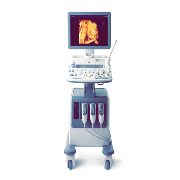
Виды клинических исследований Samsung Sonoace R7
Возможные виды клинических исследований: исследования плода, брюшной полости, педиатрические, поверхностных органов, нейросонография у детей, транскраниальная доплерография у взрослых, трансректальные, трансвагинальные, скелетно-мышечные, кардиологические у взрослых, кардиологические у детей и исследования периферических сосудов.
Технические характеристики Samsung Sonoace R7
Габариты Samsung Sonoace R7
- Высота: 1380 мм (с монитором)
- Ширина: 450 мм
- Глубина: 700 мм
- Вес: 62 кг (с монитором)
- Вес: около 75 кг (с допустимой эксплуатационной нагрузкой)
Режимы визуализации Samsung Sonoace R7
- Режим 2D
- M-режим
- Цветового доплера (ЦД) режим
- Энергетического доплера (ЭД) режим
- Направленного энергетического доплера режим
- Импульсно-волнового спектрального доплера (ИД) режим
- Непрерывно-волнового спектрального доплера (НД) режим
- Тканевого доплеровского картирования (ТДК) режим
- 3D режим
- Режим двух изображений
- Учетверенные режимы
- Комбинированные режимы
- Одновременный режим
- Режим ElastoScan (E-режим)
- Масштаб
Серая шкала
- 256 градаций (8 бит)
Фокусировка
- Фокусировка передачи, максимум по восьми точкам (одновременно можно выбрать четыре точки)
- Цифровой динамический фокус получения (непрерывный)
Датчики (тип BF/IPX7) Samsung Sonoace R7
Тип: Mini DLP
Конвексные датчики
C2-5, C2-8, C4-9, CF4-9
Линейные датчики
L3-8, L5-12/50, LN5-12
Секторные фазированные датчики
P2-4, PN2-4, SP3-8
Внутриполостные микроконвексные датчики
ER4-9, EVN4-9/10
Трехмерные датчики
3D4-8, 3D4-9, 3DC2-6, VN4-8
Карандашные датчики
CW2.0, DP2B
Тип: 156-контактные
Конвексные датчики
C2-5, C2-8, C4-9/10ED
Линейные датчики
HL5-12ED, L3-8, L5-12/50EP, LN5-12
Секторные фазированные датчики
P2-4AH, P3-7AC
Внутриполостные микроконвексные датчики
ER4-9/10ED, EV4-9/10ED
Трехмерные датчики (260-контактные)
3D4-8ET, 3D4-9ES, 3DC2-6
Подключение датчиков Samsung Sonoace R7
- 4 разъема для датчиков (включая один разъем для карандашного датчика)
Монитор Samsung Sonoace R7
- 19-дюймовый ЖК-монитор (светодиодная подсветка)
ЭКГ Samsung Sonoace R7 ЭКГ
- Тип CF
Входные и выходные разъемы
- Левый и правый аудиовыходы VHS и SVHS
- Дистанционное управление и черно-белый видеопринтер
- VGA-монитор
- Параллельный порт
- Порт USB
- LAN
Сохранение изображений
- Максимум 7084 кадров в памяти клипов
- Максимум 8192 строки в памяти петли
- Программа работы с файлами изображений
Программа Samsung Sonoace R7
Акушерское, гинекология, абдоминальное, кардиология, урология, сосуды, малые органы, скелет и мышцы, ТКД, педиатрия
Электропитание
100–120 В/200–240 В переменного тока, 680 ВА, 50/60 Гц
Пакеты для измерений
Акушерство, гинекология, кардиология, сонная артерия, ЭКГ плода, артерии верхних конечностей, артерии нижних конечностей, вены верхних конечностей, вены нижних конечностей, урология, радиология, ТКД, щитовидная железа, молочные железы, яички, поверхностные органы, тазобедренный сустав детей, скелет и мышцы
Обработка сигнала (предварительная обработка)
- Управление КОЭ
- Усиление, независимое от режима
- Контроль мощности акустического сигнала (регулируемый)
- Динамическая апертура
- Динамическая аподизация
- Динамического диапазона (регулируемый) контроль
- Области просмотра изображения контроль
- Скорости развертки в M-режиме контроль
Обработка сигнала (постобработка)
- Усреднение кадров
- Усиление/размытие краев
- Регулировка гаммы методом окна
- Ориентация изображения (слева/справа и вверху/внизу, поворот)
- Белое на черном/черное на белом
- Масштаб
Измерение
- Управление несколькими курсорами с помощью трекбола 2D-режим: линейные измерения и измерения площади с использованием эллиптической аппроксимации или обведения контуров
- M-режим: непрерывное считывание расстояния, времени и коэффициента наклона
- Режим спектрального доплера: скорость и расчет по контуру спектральной кривой
Дополнительные устройства
- Видеомагнитофон
- Принтер печати из видеопамяти
- Цветной принтер печати из видеопамяти
- Цифровой видеопринтер с подключением по USB
- Цветной видеопринтер с подключением по USB
- Жесткий диск с подключением по USB
- Контроллер беспроводной сети с подключением по USB
- Ножной переключатель с подключением по USB (IPX1)
- Флеш-накопитель USB
- Монитор
- Микрофон
- Маркер движения e-Motion Marker (IPX7)
Язык интерфейса пользователя
Английский, немецкий, французский, испанский, итальянский, русский, китайский, португальский
Конфигурация и установка оборудования Sonoace R7
Оборудование включает в себя монитор, панель управления, консоль, периферийные устройства и датчики.

1 Монитор
2 Стойка монитора
3 Динамик
4 Клавиатура и панель управления
5 Держатель для датчиков
6 Рукоятка
7 Место крепления кабеля
8 Подъемник
9 Привод DVD
10 Разъем для датчиков
11 Колесо
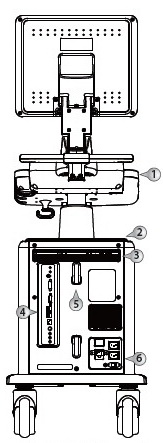
1 Рукоятка (дополнительно)
2 Полка
3 Вентиляционные отверстия
4 Задняя панель
5 Держатели для кабеля
6 Разъем для подключения кабеля питания
Экран монитора
На экран выводятся ультразвуковые изображения, меню операций и другая информация. На экране, показанном на рисунке ниже, содержится следующая информация: ① Область заголовка, ② Меню, ③ Область изображения, ④ Область эскизов, ⑤ Область данных пользователя, ⑥ Программное меню.
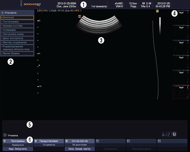
Область заголовка
В области заголовка отображается имя пациента, название лечебного учреждения, вид исследования, частота кадров и глубина сканирования, информация о датчике, данные об акустическом выходном сигнале, дата и время.
Меню
Отображается меню настройки или меню измерений.
Область изображения
В области изображения отображается ультразвуковое изображение, информация о нем, аннотации и данные измерений.
Область эскизов
При нажатии кнопки Сохранить в этой области отображаются сохраненные изображения. Если поместить курсор трекбола на эскиз и нажать, изображение будет увеличено. В этой области одновременно отображаются до 7 изображений.
Область информации пользователя
В области информации пользователя содержатся разнообразные сведения, необходимые для использования системы, например текущее состояние системы, информация об изображении, доступные элементы, маркеры частей тела и т. п.
Программное меню
В меню отображаются различные элементы управления в зависимости от текущего состояния системы. Для установки или изменения элементов программного меню используйте соответствующие кнопки гибкого программного меню на панели управления.
Панель управления
Управление системой осуществляется с помощью панели управления.
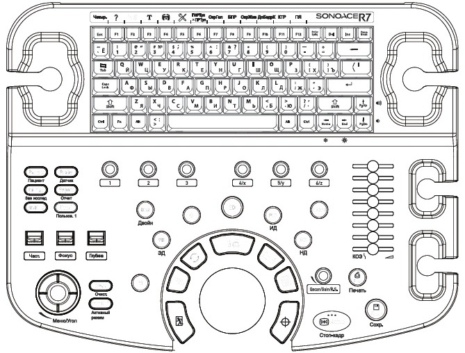
Панель управления состоит из клавиатуры, кнопок, кнопок-дисков, переключателей, ползунков и шарового манипулятора — трекбола.
Кнопка-диск может использоваться и как кнопка, и как диск.
Клавиатура
Клавиатура позволяет осуществлять ввод текста и быстро запускать различные функции с помощью функциональных клавиш.
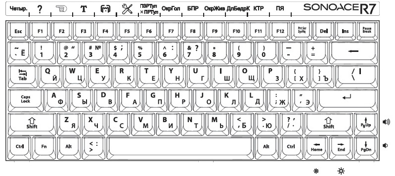
Консоль
Консоль состоит из двух частей – внутреннего и наружного блока. Внутри консоль в основном содержит устройства, ответственные за создание ультразвуковых изображений. С внешней стороны консоли расположены различные разъемы, держатели для датчиков, отсеки для принтеров и видеомагнитофона, рукоятки, колесики и т. п.
Задняя панель
К задней панели системы подключаются монитор и другие периферийные устройства, такие как принтер, видеомагнитофон и т. д.
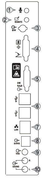
1 Разъем микрофона (вход): служит для подключения микрофона.
2 Порт для подключения дистанционного управления принтером (выход): позволяет осуществлять печать с контрольной панели УЗ — прибора.
3 Порт для подключения аналогового ч/б эхо-принтера (выход): служит для подключения эхо-принтера.
4 Параллельный порт (выход): служит для подключения цифрового принтера и ножного переключателя.
5 Порт DVI (выход): служит для вывода цифрового сигнала на дополнительный монитор.
6 Порт USB: служит для подключения периферийных USB-устройств.
7 Сетевой разъем: служит для подключения к локальной сети (LAN). Данные пациента могут быть переданы на другие серверы через
DICOM.
8 Порт S-VHS (выход): служит для подключения S-VHS видеомагнитофона.
9 Порт VHS (выход): служит для подключения VHS видеомагнитофона.
10 Аудиовыход (выход): служит для вывода аудиосигнала.
Периферийные устройства
Внутренние периферийные устройства
Это периферийные устройства, установленные в системе.
DVD-Multi
DVD+R, DVD+R DL, DVD+RW, DVD-R, DVD-R DL, DVD-RW, DVD-RAM, DVD-ROM, CD-ROM, CD-R, CD-RW.
НЖМД
Мин. 200 ГБ, SATA.
Внешние периферийные устройства
Видеомагнитофон с возможностью записи
Panasonic MD835, SONY DVO-1000MD, JVC BD-X201.
Принтер печати из видеопамяти
- XXЦветные принтеры: Mitsubishi CP910U, Mitsubishi CP910E, SONY UP-20
- XXЧерно-белые принтеры: Mitsubishi P93W, SONY UP-897MD
Видеопринтер с подключением по USB
- XXЦветные принтеры: Mitsubishi 30DW, SONY UP-D23MD, SONY UP-D25MD
- XXЧерно-белые принтеры: Mitsubishi P93DW, Mitsubishi P95D, SONY UP-D897, SONY UP-X898MD
Аксессуары
С оборудованием поставляется коробка с аксессуарами, представленными ниже.
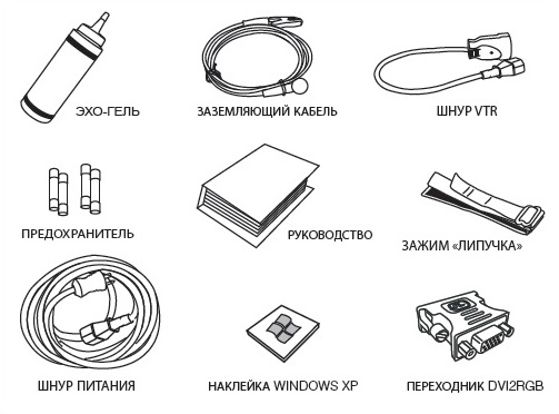
Опции
Оборудование поддерживает следующие дополнительные функции:
- 4D
- 3D XI
- Кардиологические измерения
- Пространственный компаундинг
- ElastoScan
- Стресс-эхо
- Деформация
- DICOM
- Авто ТИМ
- Авто IMT+
- Функция НД
- ДинамMR/ДинамMR+
- Панорамный
- Маркер движения e-Motion Marker
Скачать инструкцию на УЗИ Samsung Sonoace R7
Скачать инструкцию и другую документацию на УЗИ аппарат Samsung Sonoace R7 можно здесь.
Руководство пользователя ( user manual ) Samsung Sonoace R7 на русском языке скачать.
Справочное руководство ( Reference Manual ) Samsung Sonoace R7 скачать.
Регистрационное удостоверение Samsung Sonoace R7 скачать.
Также смотрите УЗИ аппарата LOGIQ S8 GE.