
Рекомендуемые жидкости и смазочные материалы
Тип: Оригинальное моторное масло Ssangyong l
(отвечающее стандартам MB Sheet 229.1 или 229.3 или 229.31 —
для дизельных/бензиновых двигателей без CDPF)
(отвечающее стандартам MB Sheet 229.31 для дизельных
двигателей, оборудованных CDPF)
Вязкость: в соответствии со стандартом MB Sheet № 224.1
Оригинальная охлаждающая жидкость Ssangyong
Антифриз SYC-1025,
Антифриз : вода = 50 : 50
НА ОСНОВЕ ОРГАНИЧЕСКОЙ КИСЛОТЫ, ЦВЕТ: ГОЛУБОЙ
Оригинальная жидкость Ssangyong
(Shell ATF 134 или Fuchs ATF 134)
Оригинальная жидкость Ssangyong (FUCHS TITAN ATF 3292)
Оригинальная жидокость Ssangyong (ATF DEXRON II)
Оригинальная жидокость Ssangyong (ATF DEXRON II или III)
Оригинальное масло Ssangyong (SAE 80W/90, API GL-5)
Оригинальное масло Ssangyong
(Синтетическое масло Shell GL75W/90)
Оригинальное масло Ssangyong (SAE 80W/90, API GL-5)
Оригинальное масло Ssangyong
(Синтетическое масло Shell GL75W/90)
Оригинальная тормозная жидкость Ssangyong (DOT4)
Оригинальное масло Ssangyong (ATF DEXRON II или III)
* TOTAL FLUIDE DA или SHELL LHM-S
≒
7,5л
≒
8,5л
≒
7,5л
≒
9,0л
10,5 ~ 11,0л
11,0 ~ 11,5л
10,5 ~ 11,0л
11.5 ~ 12.0л
≒
8,0л
≒
9,5л
4WD: ≒ 3,6л, 2WD: ≒ 3,4л
≒
1,4л
≒
1,1л
≒
1,4л
≒
1,4л, ≒ 1,5л
≒
1,4л
≒
0,78л
МКП (D20DT, G23D) ≒ 1,9л
D27DT (ВСЕ), D20DT (АКП),
G23D (АКП) ≒ 2,0л
≒
1,8л
≒
1,5л
По мере необходимости
≒
1,0л
Моторное
масло
Охлаждающая
жидкость
Рабочая жидкость автоматической
коробки передач
Масло механической коробки передач
Масло раздаточной
коробки
Масло
редуктора
моста
Рабочая жидкость для гидропривода сцепления / тормоза
Жидкость гидроусилителя рулевого управления
Передний
Задний
Part Time
AWD
Без IOP
IOP
Неразрезной
LD
IRDA
Дизельный
двигатель
Бензиновый
двигатель
Дизельный
двигатель
Бензиновый
двигатель
Наименование
Заправочная емкость
D20DT
D27DT
G23D
G32D
D20DT
D27DT
G23D
G32D
DC5
6-ступ. АКП
D20DT
D27DT
G23D
Спецификации
- Manuals
- Brands
- SSANGYONG Manuals
- Automobile
- KYRON 2008.07
- Manual
-
Contents
-
Table of Contents
-
Bookmarks
Related Manuals for SSANGYONG KYRON 2008.07
Summary of Contents for SSANGYONG KYRON 2008.07
-
Page 1
GENERAL INFORMATION 0000-00 GENERAL INFORMATION GENERAL INFORMATION 1. HOW TO READ ELECTRICAL WIRING DIAGRAM……….2. 2. LAYOUT OF ELECTRICAL SYSTEM. -
Page 3
— Internal circuit of component (Switch) (Component Name, Terminal Number and Connecting Wiring Circuit) — Lower horizontal line : Ground line ·Ground position (G101 ~ G402) ·B : Body Ground ·Refer to Major Ground Position (Section2) GENERAL INFORMATION KYRON 2008.07… -
Page 4
Battery Voltage (B+) supply in Ignition Switch “ON” and “ACC” Battery Voltage (B+) supply directly regardless of Ignition Switch Ground connected to battery (-) Battery Voltage (B+) supply in Head Lamp Switch 1st and 2nd step (Illumination circuit) GENERAL INFORMATION KYRON 2008.07… -
Page 5
□ 5□□ In the locating section, the assignment for part number startsfrom left bottom and proceeds clockwise. In the fuse and relay box or the instrument panel, the partnumber is assigned from left top to light bottom. GENERAL INFORMATION KYRON 2008.07… -
Page 7
CONNECTOR/GROUND 8201-00/8210-00/8210-02/8210-03/8210-09/8210-10/8210-06/8210-07/8210-08 CONNECTOR/GROUND WIRING HARNESS 0000-00 WIRING HARNESS, COMPONENTS LOCATION.. -
Page 9
0000-00 WIRING HARNESS WIRING HARNESS, COMPONENTS LOCATION 0000-00 1) WIRING HARNESS 2) COMPONENTS LOCATION CONNECTOR/GROUND KYRON 2008.07… -
Page 10
0000-00 3) CONNECTOR, GROUND & SPLICE PACK INFORMATION ▶ CONNECTOR CONNECTOR/GROUND KYRON 2008.07… -
Page 11
0000-00 4) SPLICE PACK CIRCUIT ▶ GROUND ▶ S101 ▶ S201 ▶ SPLICE PACK ▶ S202 (CAN) CONNECTOR/GROUND KYRON 2008.07… -
Page 12
0000-00 ▶ S203 (GND) ▶ S206 ▶ S301 (CAN) ▶ S204 (ILL+) ▶ S302 ▶ S205 (GND) CONNECTOR/GROUND KYRON 2008.07… -
Page 13
0000-00 5) CONNECTOR ▶ ▶ WIRNING CONNECTOR WIRNING CONNECTOR ▶ WIRNING CONNECTOR ▶ MODE CONNECTOR CONNECTOR/GROUND KYRON 2008.07… -
Page 14
0000-00 ▶ UNIT CONNECTOR ▶ SWITCH CONNECTOR ▶ LAMP CONNECTOR ▶ SENSOR CONNECTOR CONNECTOR/GROUND KYRON 2008.07… -
Page 15
0000-00 ▶ ETC. CONNECTOR/GROUND KYRON 2008.07… -
Page 17: Table Of Contents
POWER DISTRIBUTION 8410-02/8410-04/8401-06 POWER DISTRIBUTION FUSE/RELAY 8210-00 ENGINE ROOM FUSE / RELAY BOX……… 8410-00 I/P — LH FUSE / RELAY BOX..8401-00 I/P — RH FUSE / RELAY BOX..ELECTRICITY DIVIDE 8210-00 ENGINE ROOM FUSE / RELAY BOX CIRCUIT….8410-00 I/P — LH FUSE / RELAY BOX CIRCUIT….
-
Page 19: Fuse/Relay
8210-00 FUSE / RELAY ENGINE ROOM FUSE / RELAY BOX 8210-00 1) UPPER 3) ENGINE ROOM FUSE / RELAY BOX 2) LOW 4) ENGINE ROOM FUSE / RELAY BOX (RUSSIA) POWER DISTRIBUTION KYRON 2008.07…
-
Page 20
8210-00 5) USAGE OF FUSE IN ENGINE ROOM FUSE BOX 6) ENGINE ROOM FUSE BOX CONNECTOR NUMBER POWER DISTRIBUTION KYRON 2008.07… -
Page 21: I/P — Lh Fuse / Relay Box
8410-00 I/P — LH FUSE / RELAY BOX 8410-00 1) I/P — LH FUSE / RELAY BOX 2) POWER SUPPLY POWER DISTRIBUTION KYRON 2008.07…
-
Page 22: I/P — Rh Fuse / Relay Box
8410-00 I/P — RH FUSE / RELAY BOX 8410-00 1) I/P — RH FUSE / RELAY BOX POWER DISTRIBUTION KYRON 2008.07…
-
Page 23: Electricity Divide
8210-00 ELECTRICITY DIVIDE ENGINE ROOM FUSE / RELAY BOX CIRCUIT 8210-00 1) SB5, SB6, Ef4, Ef5, Ef11, HORN RELAY, HEAD LAMP RELAY (HI, LO) 2) SB2 ~ SB4, SB7 ~ SB9, Ef3, P/WINDOW RELAY POWER DISTRIBUTION KYRON 2008.07…
-
Page 24
8210-00 3) SB10 ~ SB11, CONDENSOR FAN RELAY (HI, LO) 4) SB12 ~ SB16, START RELAY, PTC RELAY POWER DISTRIBUTION KYRON 2008.07… -
Page 25
8210-00 5) Ef1, Ef2, Ef6, Ef7 6) Ef8 ~ Ef10, TAIL LAMP RELAY, FRT FOG LAMP RELAY POWER DISTRIBUTION KYRON 2008.07… -
Page 26
0-10 8210-00 7) Ef12 ~ Ef14, ENG MOUNT RELAY, COMPRESSOR RELAY Ef15 ~ Ef23 POWER DISTRIBUTION KYRON 2008.07…
 -
Page 27
0-11 8210-00 9) WIPER MOTOR RELAY (HI, LO), WASHER RELAY (FRT, RR) POWER DISTRIBUTION KYRON 2008.07… -
Page 28: I/P — Lh Fuse / Relay Box Circuit
0-12 8410-00 I/P — LH FUSE / RELAY BOX CIRCUIT 8410-00 1) F24 ~ F28 2) F29 ~ F34 POWER DISTRIBUTION KYRON 2008.07…
-
Page 29
0-13 8410-00 3) F35 ~ F40, RR WIPER RELAY 4) F41 ~ F48 POWER DISTRIBUTION KYRON 2008.07… -
Page 30
0-14 8410-00 5) F49 ~ F51, RR FOG LAMP RELAY 6) F52 ~ F55, BURGLAR HORN RELAY, RR SEAT WARMER RELAY POWER DISTRIBUTION KYRON 2008.07… -
Page 31
0-15 8410-00 7) F56 ~ F57, HDC RELAY, FLASHER UNIT POWER DISTRIBUTION KYRON 2008.07… -
Page 32: I/P — Rh Fuse / Relay Box Circuit
0-16 8410-00 I/P — RH FUSE / RELAY BOX CIRCUIT 8410-00 1) F58 ~ F64, ENG MAIN RELAY 2) F65 ~ F71, SHIFT RELAY (4-A/T) POWER DISTRIBUTION KYRON 2008.07…
-
Page 33
0-17 8410-00 3) BLOWER RELAY, INJECTOR RELAY, SNR RELAY 4) FOLD’G RELAY, UNFOLD’G RELAY POWER DISTRIBUTION KYRON 2008.07… -
Page 34: Icm Relay Box Circuit
0-18 84100-00 ICM RELAY BOX CIRCUIT 8410-00 1) DEICER RELAY, DR LOCK/UNLOCK RELAY 2) HAZARD RELAY, DRL SIGNAL POWER DISTRIBUTION KYRON 2008.07…
-
Page 36
CIRCUIT 1461-01/2820-01/1491-01/1491-01/8210-01/3110-01/3410-01/4892-01/4620-12/8810-01/8010-01/7410-13/7410-02/7410-04/8510-52/8510-48/8710-02/7830-03/ 8510-05/8610-06/7632-16/7340-03/8310-01/8510-00/8320-01/8410-01/8210-01/8310-10/4810-01/7770-02/7770-10/8910-01/8930-01/8790-01/6810-15/6910-01/6810- CIRCUIT ELECTRIC ENGINE 8810-00 AIR-BAG (CURTAIN AIR-BAG)..1461-00 STARTING / CHARGING….7770-00INTERIOR LAMP CIRCUIT… 8010-00 CLUSTER……..2820-00 PREHEATING CIRCUIT….7770-0 AUTO DIMMING ROOM 7410-00 POWER SEAT — DRIVER 1491-00 ECU (ENGINE CONTROL MIRROR CIRCUIT……(W/ MEMORY)……. UNIT — D20/D27DT EU-IV)…. 8910-00AUDIO / CLOCK CIRCUIT.. -
Page 38
1461-00 STARTING / CHARGING (1) CONNECTOR INFORMATION 1461-00 5-AT, M/T (2) CONNECTOR IDENTIFICATION SYMBOL & PIN NUMBER POSITION CIRCUIT KYRON 2008.07… -
Page 39
1461-00 6-A/T, 4-A/T (1) CONNECTOR INFORMATION (2) CONNECTOR IDENTIFICATION SYMBOL & PIN NUMBER POSITION CIRCUIT KYRON 2008.07… -
Page 40
2820-00 PREHEATING CIRCUIT (1) CONNECTOR INFORMATION 2820-00 (2) CONNECTOR IDENTIFICATION SYMBOL & PIN NUMBER POSITION CIRCUIT KYRON 2008.07… -
Page 41
ECU (ENGINE CONTROL UNIT — D20/D27DT EU-IV) ECU (ENGINE CONTRIV) (1) CONNECTOR INFORMATION 1491-00 ENG MAIN RELAY, INTAKE THROTTLE, A/CRUISE SW, VALVE (EGR, WASTE GATE, INLET METERING), SENSOR (HFM, PEDAL) (2) CONNECTOR IDENTIFICATION SYMBOL & PIN NUMBER POSITION CIRCUIT KYRON 2008.07… -
Page 42
1491-00 2) SENSOR (FUEL PRESSURE, CAM SHAFT, BOOSTER PRESSURE, (1) CONNECTOR INFORMATION CRANK SHAFT, KNOCK, FUEL TEMP, FUEL FILTER WARNING), PTC RELAY (2) CONNECTOR IDENTIFICATION SYMBOL & PIN NUMBER POSITION CIRCUIT KYRON 2008.07… -
Page 43
INJECTOR, STOP LAMP, IMMOBILIZER, CLUSTER, PREHEATING UNIT, INJECTOR, STOP LAMP, IMMOBILIZER, CLUSTER, PREHEATING UNIT, (1) CONNECTOR INFORMATION SENSOR (EXHAUST GAS TEMP), TRIPPLE PRESSURE SW SENSOR (EXHAUST GAS TEMP), TRIPPLE PRESSURE SW (2) CONNECTOR IDENTIFICATION SYMBOL & PIN NUMBER POSITION CIRCUIT KYRON 2008.07… -
Page 44
1491-00 ECU (ENGINE CONTROL UNIT — D20/D27DT) (1) CONNECTOR INFORMATION 1491-00 ENG MAIN RELAY, PEDAL SENSOR, HFM SENSOR, VALVE, CRUISE CONTROL SW, ENG MOUNT RELAY (2) CONNECTOR IDENTIFICATION SYMBOL & PIN NUMBER POSITION CIRCUIT KYRON 2008.07… -
Page 45
0-10 1491-00 2) FUEL FILTER WARNING LAMP, IMMOBILIZER, SENSOR (FUEL (1) CONNECTOR INFORMATION PRESSURE, CAM SHAFT, BOOSTER PRESSURE, CRANK SHAFT, KNOCK, COOLANT TEMP., FUEL TEMP.) (2) CONNECTOR IDENTIFICATION SYMBOL & PIN NUMBER POSITION CIRCUIT KYRON 2008.07… -
Page 46
0-11 1491-00 3) INJECTOR, CAN LINE (1) CONNECTOR INFORMATION (2) CONNECTOR IDENTIFICATION SYMBOL & PIN NUMBER POSITION CIRCUIT KYRON 2008.07… -
Page 47
0-12 1490-00 ECU (ENGINE CONTROL UNIT — GSL G32) (1) CONNECTOR INFORMATION 1490-00 IGN COIL, INJECTOR, PEDAL MODULE, THROTTLE SENSOR (2) CONNECTOR IDENTIFICATION SYMBOL & PIN NUMBER POSITION CIRCUIT KYRON 2008.07… -
Page 48
0-13 1490-00 2) O₂SENSOR, CPS, KNOCK SENSOR, HFM SENSOR, CANISTER PURGE (1) CONNECTOR INFORMATION VALVE (2) CONNECTOR IDENTIFICATION SYMBOL & PIN NUMBER POSITION CIRCUIT KYRON 2008.07… -
Page 49
0-14 1490-00 3) S/AIR PUMP, STOP LAMP, CRUISE CONTROL SW, FUEL PUMP, (1) CONNECTOR INFORMATION IMMOBILIZER (2) CONNECTOR IDENTIFICATION SYMBOL & PIN NUMBER POSITION CIRCUIT KYRON 2008.07… -
Page 50
0-15 1490-00 ECU (ENGINE CONTROL UNIT — GSL G23) (1) CONNECTOR INFORMATION 1490-00 IGN COIL, INJECTOR, PEDAL MODULE, THROTTLE SENSOR (2) CONNECTOR IDENTIFICATION SYMBOL & PIN NUMBER POSITION CIRCUIT KYRON 2008.07… -
Page 51
0-16 1490-00 2) O₂SENSOR, CPS, KNOCK SENSOR, MAP SENSOR, CANISTER PURGE (1) CONNECTOR INFORMATION VALVE (2) CONNECTOR IDENTIFICATION SYMBOL & PIN NUMBER POSITION CIRCUIT KYRON 2008.07… -
Page 52
0-17 1490-00 3) STOP LAMP, CRUISE CONTROL SW, FUEL PUMP, IMMOBILIZER (1) CONNECTOR INFORMATION (2) CONNECTOR IDENTIFICATION SYMBOL & PIN NUMBER POSITION CIRCUIT KYRON 2008.07… -
Page 53
0-18 8210-00 DIAGNOSIS CIRCUIT (1) CONNECTOR INFORMATION 8210-00 (2) CONNECTOR IDENTIFICATION SYMBOL & PIN NUMBER POSITION CIRCUIT KYRON 2008.07… -
Page 54
0-19 3110-00 TCU (6-A/T) (1) CONNECTOR INFORMATION 3110-00 1) START MOTOR, TGS LEVER, INHIBITOR SW (2) CONNECTOR IDENTIFICATION SYMBOL & PIN NUMBER POSITION CIRCUIT KYRON 2008.07… -
Page 55
0-20 3110-00 2) SOLENOID, OIL TEMP SENSOR, SPEED SENSOR (N2, N3) (1) CONNECTOR INFORMATION (2) CONNECTOR IDENTIFICATION SYMBOL & PIN NUMBER POSITION CIRCUIT KYRON 2008.07… -
Page 56
0-21 3110-00 TCU (5-A/T) (1) CONNECTOR INFORMATION 3110-00 1) START MOTOR, TGS LEVER, CAN LINE (2) CONNECTOR IDENTIFICATION SYMBOL & PIN NUMBER POSITION CIRCUIT KYRON 2008.07… -
Page 57
0-22 3110-00 2) SOLENOID, OIL TEMP SENSOR, SPEED SENSOR (N2, N3) (1) CONNECTOR INFORMATION (2) CONNECTOR IDENTIFICATION SYMBOL & PIN NUMBER POSITION CIRCUIT KYRON 2008.07… -
Page 58
0-23 3110-00 TCU (4-A/T) (1) CONNECTOR INFORMATION 3110-00 (2) CONNECTOR IDENTIFICATION SYMBOL & PIN NUMBER POSITION CIRCUIT KYRON 2008.07… -
Page 59
0-24 3740-00 A/T SHIFT LOCK (4-A/T) (1) CONNECTOR INFORMATION 3740-00 (2) CONNECTOR IDENTIFICATION SYMBOL & PIN NUMBER POSITION CIRCUIT KYRON 2008.07… -
Page 60
0-25 3410-00 TCCU (1) CONNECTOR INFORMATION 3410-00 (2) CONNECTOR IDENTIFICATION SYMBOL & PIN NUMBER POSITION CIRCUIT KYRON 2008.07… -
Page 61
0-26 4480-00 (1) CONNECTOR INFORMATION 4480-00 (2) CONNECTOR IDENTIFICATION SYMBOL & PIN NUMBER POSITION CIRCUIT KYRON 2008.07… -
Page 62
0-27 4920-00 (1) CONNECTOR INFORMATION 4920-00 (2) CONNECTOR IDENTIFICATION SYMBOL & PIN NUMBER POSITION CIRCUIT KYRON 2008.07… -
Page 63
0-28 4892-00 ABS/ESP (TPMS) (1) CONNECTOR INFORMATION 4892-00 W/SPEED SENSOR, STOP LAMP SW, DIAGNOSIS, WARNING LAMP (ABS/ESP), HDC (2) CONNECTOR IDENTIFICATION SYMBOL & PIN NUMBER POSITION CIRCUIT KYRON 2008.07… -
Page 64
0-29 4892-00 PRESSURE SENSOR, S.W.A SENSOR, SENSOR CLUSTER, ESP OFF SW (1) CONNECTOR INFORMATION (2) CONNECTOR IDENTIFICATION SYMBOL & PIN NUMBER POSITION CIRCUIT KYRON 2008.07… -
Page 65
0-30 4620-00 S.S.P.S (SPEED SENSITIVE POWER STEERING (1) CONNECTOR INFORMATION 4620-00 (2) CONNECTOR IDENTIFICATION SYMBOL & PIN NUMBER POSITION CIRCUIT KYRON 2008.07… -
Page 66
0-31 8810-00 AIR-BAG (CURTAIN AIR-BAG) (1) CONNECTOR INFORMATION 8810-00 (2) CONNECTOR IDENTIFICATION SYMBOL & PIN NUMBER POSITION CIRCUIT KYRON 2008.07… -
Page 67
0-32 8010-00 CLUSTER (1) CONNECTOR INFORMATION 8010-00 1) GAUGE (SPEED, RPM, FUEL, TEMP), WARNING LAMP (FUEL, FUEL FILTER, ABS/ESP, BRAKE, HDC, 4WD, EPB, EAS, TPMS) (2) CONNECTOR IDENTIFICATION SYMBOL & PIN NUMBER POSITION CIRCUIT KYRON 2008.07… -
Page 68
0-33 8010-00 2) WARNING LAMP (EAS, EPB, AUTO PARK G, TPMS, GROBAL), EASY ’ (1) CONNECTOR INFORMATION ’ LOAD G, TPMS DISPLAY (2) CONNECTOR IDENTIFICATION SYMBOL & PIN NUMBER POSITION CIRCUIT KYRON 2008.07… -
Page 69
0-34 8010-00 3) WARNING LAMP (BATT CHARGE, OIL, HOOD, DOOR, ENG CHECK, AIR (1) CONNECTOR INFORMATION BAG, SSPS, SEAT BELT), TURN SIGNAL, FRT FOG, HAZARD LAMP (2) CONNECTOR IDENTIFICATION SYMBOL & PIN NUMBER POSITION CIRCUIT KYRON 2008.07… -
Page 70
0-35 7410-00 POWER SEAT — DRIVER (W/ MEMORY) (1) CONNECTOR INFORMATION 7410-00 1) DRIVER POWER SEAT / SEAT MEMORY (2) CONNECTOR IDENTIFICATION SYMBOL & PIN NUMBER POSITION CIRCUIT KYRON 2008.07… -
Page 71
0-36 7410-00 2) ELECTRIC OUTSIDE MIRROR (1) CONNECTOR INFORMATION (2) CONNECTOR IDENTIFICATION SYMBOL & PIN NUMBER POSITION CIRCUIT KYRON 2008.07… -
Page 72
0-37 7410-00 POWER SEAT — DRIVER (W/O MEMORY) (1) CONNECTOR INFORMATION 7410-00 (2) CONNECTOR IDENTIFICATION SYMBOL & PIN NUMBER POSITION CIRCUIT KYRON 2008.07… -
Page 73
0-38 7410-00 POWER SEAT — PASSENGER (1) CONNECTOR INFORMATION 7410-00 (2) CONNECTOR IDENTIFICATION SYMBOL & PIN NUMBER POSITION CIRCUIT KYRON 2008.07… -
Page 74
0-39 8510-00 null ELECTRIC OUTSIDE MIRROR / FOLDING (1) CONNECTOR INFORMATION 8510-00 (W/O MEMORY) (2) CONNECTOR IDENTIFICATION SYMBOL & PIN NUMBER POSITION CIRCUIT KYRON 2008.07… -
Page 75
0-40 8510-00 FRT SEAT WARMER (1) CONNECTOR INFORMATION 8510-00 (2) CONNECTOR IDENTIFICATION SYMBOL & PIN NUMBER POSITION CIRCUIT KYRON 2008.07… -
Page 76
0-41 8610-00 RR SEAT WARMER (1) CONNECTOR INFORMATION 8610-00 (2) CONNECTOR IDENTIFICATION SYMBOL & PIN NUMBER POSITION CIRCUIT KYRON 2008.07… -
Page 77
0-42 8710-00 STICS (1) CONNECTOR INFORMATION 8710-00 1) POWER/GROUND, CHIME BELL, BUZZER, WARNING LAMP (BRAKE, S/BELT, DR OPEN) (2) CONNECTOR IDENTIFICATION SYMBOL & PIN NUMBER POSITION CIRCUIT KYRON 2008.07… -
Page 78
0-43 8710-00 2) CENTRAL DOOR LOCK CIRCUIT (1) CONNECTOR INFORMATION (2) CONNECTOR IDENTIFICATION SYMBOL & PIN NUMBER POSITION CIRCUIT KYRON 2008.07… -
Page 79
0-44 8710-00 3) TAIL LAMP, HAZARD, POWER WINDOW (1) CONNECTOR INFORMATION (2) CONNECTOR IDENTIFICATION SYMBOL & PIN NUMBER POSITION CIRCUIT KYRON 2008.07… -
Page 80
0-45 8710-00 4) DEFOGGER (1) CONNECTOR INFORMATION (2) CONNECTOR IDENTIFICATION SYMBOL & PIN NUMBER POSITION CIRCUIT KYRON 2008.07… -
Page 81
0-46 8710-00 5) PANIC, AUTO LIGHT / RAIN SENSING, ROOM LAMP (1) CONNECTOR INFORMATION (2) CONNECTOR IDENTIFICATION SYMBOL & PIN NUMBER POSITION CIRCUIT KYRON 2008.07… -
Page 82
0-47 8710-00 6) FRT WIPER/WASHER / RR WASHER (1) CONNECTOR INFORMATION (2) CONNECTOR IDENTIFICATION SYMBOL & PIN NUMBER POSITION CIRCUIT KYRON 2008.07… -
Page 83
0-48 8710-00 ’ ’ 7) MIRROR FOLD G / UNFOLD G, FOLD SW (1) CONNECTOR INFORMATION (2) CONNECTOR IDENTIFICATION SYMBOL & PIN NUMBER POSITION CIRCUIT KYRON 2008.07… -
Page 84
0-49 7830-00 RR WIPER CIRCUIT (1) CONNECTOR INFORMATION 7830-00 (2) CONNECTOR IDENTIFICATION SYMBOL & PIN NUMBER POSITION CIRCUIT KYRON 2008.07… -
Page 85
0-50 8510-00 POWER WINDOW CIRCUIT (1) CONNECTOR INFORMATION 8510-00 (2) CONNECTOR IDENTIFICATION SYMBOL & PIN NUMBER POSITION CIRCUIT KYRON 2008.07… -
Page 86
0-51 8610-00 HORN (1) CONNECTOR INFORMATION 8610-00 (2) CONNECTOR IDENTIFICATION SYMBOL & PIN NUMBER POSITION CIRCUIT KYRON 2008.07… -
Page 87
0-52 7632-00 CIGAR LIGHTER / POWER OUTLET CIRCUIT (1) CONNECTOR INFORMATION 7632-00 (2) CONNECTOR IDENTIFICATION SYMBOL & PIN NUMBER POSITION CIRCUIT KYRON 2008.07… -
Page 88
0-53 7340-00 SUN ROOF CIRCUIT (1) CONNECTOR INFORMATION 7340-00 (2) CONNECTOR IDENTIFICATION SYMBOL & PIN NUMBER POSITION CIRCUIT KYRON 2008.07… -
Page 89
0-54 8310-00 (1) CONNECTOR INFORMATION HEAD LAMP / DRL HEAD LAMP & DRL 8310-00 (DAY TIME RUNNING LIGHT) UNIT CIRCUIT (2) CONNECTOR IDENTIFICATION SYMBOL & PIN NUMBER POSITION CIRCUIT KYRON 2008.07… -
Page 90
0-55 8510-00 (1) CONNECTOR INFORMATION 8510-00 HLLD (HEAD LAMP LEVEL’G DEVICE) CIRCUIT (2) CONNECTOR IDENTIFICATION SYMBOL & PIN NUMBER POSITION CIRCUIT KYRON 2008.07… -
Page 91
0-56 8320-00 TAIL LAMP CIRCUIT (1) CONNECTOR INFORMATION 8320-00 (2) CONNECTOR IDENTIFICATION SYMBOL & PIN NUMBER POSITION CIRCUIT KYRON 2008.07… -
Page 92
0-57 8410-00 TURN SIGNAL / HAZARD LAMP CIRCUIT (1) CONNECTOR INFORMATION 8410-00 (2) CONNECTOR IDENTIFICATION SYMBOL & PIN NUMBER POSITION CIRCUIT KYRON 2008.07… -
Page 93
0-58 8210-00 TRAILER LAMP CIRCUIT (1) CONNECTOR INFORMATION 8210-00 (2) CONNECTOR IDENTIFICATION SYMBOL & PIN NUMBER POSITION CIRCUIT KYRON 2008.07… -
Page 94
0-59 8310-00 FOG LAMP CIRCUIT (1) CONNECTOR INFORMATION 8310-00 (2) CONNECTOR IDENTIFICATION SYMBOL & PIN NUMBER POSITION CIRCUIT KYRON 2008.07… -
Page 95
0-60 4810-00 STOP / BACK-UP LAMP CIRCUIT (1) CONNECTOR INFORMATION 4810-00 (2) CONNECTOR IDENTIFICATION SYMBOL & PIN NUMBER POSITION CIRCUIT KYRON 2008.07… -
Page 96
0-61 7770-00 INTERIOR LAMP CIRCUIT (1) CONNECTOR INFORMATION 7770-00 (2) CONNECTOR IDENTIFICATION SYMBOL & PIN NUMBER POSITION CIRCUIT KYRON 2008.07… -
Page 97
0-62 7770-00 AUTO DIMMING ROOM MIRROR CIRCUIT (1) CONNECTOR INFORMATION 7770-00 (2) CONNECTOR IDENTIFICATION SYMBOL & PIN NUMBER POSITION CIRCUIT KYRON 2008.07… -
Page 98
0-63 8910-00 AUDIO / CLOCK CIRCUIT (1) CONNECTOR INFORMATION 8910-00 (2) CONNECTOR IDENTIFICATION SYMBOL & PIN NUMBER POSITION CIRCUIT KYRON 2008.07… -
Page 99
0-64 8930-00 A/V SYSTEM (1) CONNECTOR INFORMATION 8930-00 A/V HEAD UNIT, TUNER UNIT, DSP UNIT, DVD CHANGER (2) CONNECTOR IDENTIFICATION SYMBOL & PIN NUMBER POSITION CIRCUIT KYRON 2008.07… -
Page 100
0-65 8930-00 2) DSP UNIT, SPEAKER (1) CONNECTOR INFORMATION (2) CONNECTOR IDENTIFICATION SYMBOL & PIN NUMBER POSITION CIRCUIT KYRON 2008.07… -
Page 101
0-66 8790-00 PARKING AID CIRCUIT (1) CONNECTOR INFORMATION 8790-00 (2) CONNECTOR IDENTIFICATION SYMBOL & PIN NUMBER POSITION CIRCUIT KYRON 2008.07… -
Page 102
0-67 6810-00 PTC HEATER (1) CONNECTOR INFORMATION 6810-00 (POSITIVE TEMPERATURE COEFFICIENT) (2) CONNECTOR IDENTIFICATION SYMBOL & PIN NUMBER POSITION CIRCUIT KYRON 2008.07… -
Page 103
0-68 6910-00 FFH (FUEL FIRED HEATER) (1) CONNECTOR INFORMATION 6910-00 (2) CONNECTOR IDENTIFICATION SYMBOL & PIN NUMBER POSITION CIRCUIT KYRON 2008.07… -
Page 104
0-69 6810-00 FATC (FULL AUTO TEMP. CONTROL) CIRCUIT (1) CONNECTOR INFORMATION 6810-00 1) C/FAN, SENSOR, AIR MIX MOTOR (D27DT EU IV — A/T) (2) CONNECTOR IDENTIFICATION SYMBOL & PIN NUMBER POSITION CIRCUIT KYRON 2008.07… -
Page 105
0-70 6810-00 2) PWM MOTOR, AIR MIX MOTOR (D27DT EU IV — M/T) (1) CONNECTOR INFORMATION (2) CONNECTOR IDENTIFICATION SYMBOL & PIN NUMBER POSITION CIRCUIT KYRON 2008.07… -
Page 106
0-71 6810-00 (1) CONNECTOR INFORMATION 3) C/FAN, SENSOR, AIR MIX MOTOR (D27DT EU Ⅲ) (2) CONNECTOR IDENTIFICATION SYMBOL & PIN NUMBER POSITION CIRCUIT KYRON 2008.07… -
Page 107
0-72 6810-00 4) C/FAN, SENSOR, AIR MIX MOTOR (GSL 3.2) (1) CONNECTOR INFORMATION (2) CONNECTOR IDENTIFICATION SYMBOL & PIN NUMBER POSITION CIRCUIT KYRON 2008.07… -
Page 108
0-73 6810-00 5) PWM MOTOR, AIR MIX MOTOR (GSL 2.3) (1) CONNECTOR INFORMATION (2) CONNECTOR IDENTIFICATION SYMBOL & PIN NUMBER POSITION CIRCUIT KYRON 2008.07… -
Page 109
0-74 6810-00 6) BLOWER, ACTUATOR (MODE, INTAKE), AMBI SENSOR (1) CONNECTOR INFORMATION (2) CONNECTOR IDENTIFICATION SYMBOL & PIN NUMBER POSITION CIRCUIT KYRON 2008.07… -
Page 110
0-75 6810-00 AIR-CON (MANUAL) CIRCUIT (1) CONNECTOR INFORMATION 6810-00 1) COMPRESSOR, MOTOR (D27DT EU IV — A/T) (2) CONNECTOR IDENTIFICATION SYMBOL & PIN NUMBER POSITION CIRCUIT KYRON 2008.07… -
Page 111
0-76 6810-00 2) PWM MOTOR, MOTOR (D27DT EU IV — M/T) (1) CONNECTOR INFORMATION (2) CONNECTOR IDENTIFICATION SYMBOL & PIN NUMBER POSITION CIRCUIT KYRON 2008.07… -
Page 112
0-77 6810-00 (1) CONNECTOR INFORMATION 3) COMPRESSOR, MOTOR (D27DT EU Ⅲ) (2) CONNECTOR IDENTIFICATION SYMBOL & PIN NUMBER POSITION CIRCUIT KYRON 2008.07… -
Page 113
0-78 6810-00 4) COMPRESSOR, MOTOR (GSL 3.2) (1) CONNECTOR INFORMATION (2) CONNECTOR IDENTIFICATION SYMBOL & PIN NUMBER POSITION CIRCUIT KYRON 2008.07… -
Page 114
0-79 6810-00 5) PWM MOTOR, MOTOR (GSL 2.3) (1) CONNECTOR INFORMATION (2) CONNECTOR IDENTIFICATION SYMBOL & PIN NUMBER POSITION CIRCUIT KYRON 2008.07… -
Page 115
0-80 6810-00 6) BLOWER (1) CONNECTOR INFORMATION (2) CONNECTOR IDENTIFICATION SYMBOL & PIN NUMBER POSITION CIRCUIT KYRON 2008.07… -
Page 117
FATC controller. This sensor is installed at the front bottom of Ambient Temperature Sensor engine compartment. This changes the air source mode by detecting the air pollution and the ambient temperature. Ambient temperature sensor AIR CONDITIONER KYRON 2008.07… -
Page 118
Absorbs moisture in the Detects A/C switch position, A sensor that detects coolant refrigerant and reserves coolant temperature, engine temperature and transmits to refrigerant to supply smoothly. condition and driving condition engine ECU. to control the air conditioner. AIR CONDITIONER KYRON 2008.07… -
Page 119
01-4 6810-20 2. VENTILATION SYSTEM COMPONENTS Locations of Vents ▶ ▶ Air Duct AIR CONDITIONER KYRON 2008.07… -
Page 120
Mode door actuator Coolant temperature detection sensor Air source door actuator Power transistor Blower motor Air mix door actuator Main wire connector Intake sensor Active incar sensor (interior temperature sensor) and humidity sensor Air conditioner controller unit AIR CONDITIONER KYRON 2008.07… -
Page 121
Coolant Temperature Sensor Power Transistor/Blower Intake Sensor Motor Power transistor Blower motor Air Source Door Actuator Air Conditioner Filter Interior Temperature Sensor A/C Controller Unit (Interior Humidity Sensor) Mode Door Actuator Interior temperature and humidity sensor AIR CONDITIONER KYRON 2008.07… -
Page 122
01-7 6810-15 3) Components AIR CONDITIONER KYRON 2008.07… -
Page 123
01-8 6810-15 4. PTC HEATER AND FFH HEATER LAYOUT 1) PTC HEATER ASSEMBLY LAYOUT 2) FFH HEATER ASSEMBLY LAYOUT AIR CONDITIONER KYRON 2008.07… -
Page 124
01-9 6810-15 5. AMBIENT TEMPERATURE SENSOR The ambient temperature sensor is installed in the front area of the engine compartment to detect the ambient temperature. Ambient temperature sensor Ambient temperature sensor Connector AIR CONDITIONER KYRON 2008.07… -
Page 125
Measure the voltage to the sun sensor from FATC connector. (approx. 2.5 V under sunlight and 4.8 V under shade.) If the voltage value cannot be measured, check the circuit for open. If the measured value is within the specified range, replace the FATC controller. AIR CONDITIONER KYRON 2008.07… -
Page 126
Incar temperature sensor ▶ This sensor is a negative temperature coefficient (NTC) thermistor and detects the interior temperature with air coming from sensor hole and then sends the voltage value according to the changed resistance to FATC controller. AIR CONDITIONER KYRON 2008.07… -
Page 127
Coolant temperature: over 115°C For approx. 4 seconds after starting the engine When engine speed is below 650 rpm When engine speed is over 4,500 rpm During abrupt acceleration for the vehicle equipped with manual transmission AIR CONDITIONER KYRON 2008.07… -
Page 128
FATC controller connector. (standard: approx. 2 V at 25°C) If the voltage value cannot be measured, check the circuit for open. If the measured value is within the specified range, replace the FATC controller. AIR CONDITIONER KYRON 2008.07… -
Page 129
Measure the voltage between terminals while changing the fan speed from stage 1 to stage 6. The specified voltage value in each stage: If the voltage is out of specified value, check the circuit for open. If the circuit is in normal condition, replace the power transistor. AIR CONDITIONER KYRON 2008.07… -
Page 130
FOOT and DEF mode to change the air flow directions according to FATC controller. Under the FATC controller AUTO mode, it stays on DEF mode until the engine coolant temperature reaches at normal operating level and the mode is changed as below when the MODE switch is pressed. Mode door actuator AIR CONDITIONER KYRON 2008.07… -
Page 131
And measure the voltage between terminal A12 and A11 on the FATC controller connector. (standard: approx. 12 V) If the voltage value cannot be measured, check the circuit for open. If the measured value is within the specified range, replace the FATC controller. AIR CONDITIONER KYRON 2008.07… -
Page 132
2 minutes to burn the residual fuel inside the system when stopping the engine during its operation. Therefore, a certain period of FFH operation after stopping the engine is not a malfunction. Components Locator AIR CONDITIONER KYRON 2008.07… -
Page 133
4. FFH water pump bracket 10. Fuel pump bracket 16. Intake hose 5. FFH NO.3 inlet hose 11. Fuel pipe NO.1 17. Clamp 6. FFH NO.2 inlet hose 12. Fuel pipe NO.2 18. FFH NO.1 inlet hose AIR CONDITIONER KYRON 2008.07… -
Page 134
01-19 6810-15 (2) Exploded View AIR CONDITIONER KYRON 2008.07… -
Page 135
01-20 6810-15 AIR CONDITIONER KYRON 2008.07… -
Page 136
15. Bush for flame sensor (graphite) 32. Screw (M4 x 16 TORX / 4x) 16. Control and overheating sensor with cable 33. Screw (M4 x 44 TORX / 4x) 17. O-ring 34. Controller cable harness 35. Insulation washer AIR CONDITIONER KYRON 2008.07… -
Page 137
01-22 6810-15 (3) SPECIFICATIONS AIR CONDITIONER KYRON 2008.07… -
Page 138
80°C and starts to be operated in LO mode (low output: approx. 2,300 W) from 81°C. When the coolant temperature reaches at approx. 85°C, FFH stops its operation until the operating conditions will be met again. AIR CONDITIONER KYRON 2008.07… -
Page 139
Fill the heater and water hoses with coolant before connecting to the coolant circuit. When routing the coolant pipes, observe a sufficient clearance to hot vehicle parts. Protect all coolant hoses/coolant pipes from chafing and from extreme temperatures. Secure all hose connections with hose clamps. AIR CONDITIONER KYRON 2008.07… -
Page 140
01-25 6810-15 4) Circuit Diagram AIR CONDITIONER KYRON 2008.07… -
Page 141
It is possible to diagnose the system by connecting the diagnostic device to controller. For details, refer to the «Diagnosis Procedures» section. If an emergency shutdown -EMERGENCY OFF- is necessary during operation, proceed as follows; Pull the fuse (Ef6: 20A) out. Disconnect the heater from the battery. AIR CONDITIONER KYRON 2008.07… -
Page 142
01-27 6810-15 6) Specification — Water Pump 7) Characteristic Curve of Water Pump (12 V) AIR CONDITIONER KYRON 2008.07… -
Page 143
01-28 6810-15 Function Diagram 9) Switching Diagram According to Temperature Changes AIR CONDITIONER KYRON 2008.07… -
Page 144
These are located inside the left and right B-pillar panel bottoms. When collision occurs, the air bag at the side of collision deploys accordingly. Please pay attention to that, in the case of the curtain air bag, only the air bag at the side of collision deploys, not both. AIR BAG KYRON 2008.07… -
Page 145
The new curtain air bag for the deployed side, the air bag unit and its connection wires (connectors included), the collision G sensor assembly for the curtain air bag, and the trims and roof headlining for the broken parts. AIR BAG KYRON 2008.07… -
Page 146
These are located inside the left and right B-pillar panel bottoms. When a collision occurs, the air bag at the side of collision deploys accordingly. Please pay attention to that, in the case of the curtain air bag, only the air bag at the side of collision deploys, not both. AIR BAG KYRON 2008.07… -
Page 147
Please do not connect a tester to any air bag connector or single item to measure the supplied power or resistance. The detonator may explode due to a sudden extra power supplied by the tester. Before removing or installing any air bag related components, disconnect the negative battery cable. AIR BAG KYRON 2008.07… -
Page 149
02-8 8810-03 2. AIR BAG SYSTEM LOCATIONS AND RELATED COMPONENTS ▶ When the curtain air bag (LH) deploys Curtain air bag collision G sensor BPT: Belt Pretensioner ▶ When the curtain air bag (RH) deploys AIR BAG KYRON 2008.07… -
Page 150
When the front collision G sensor sends out only the air bag deployment signal, the signal deploys the two front air bags and activates their seat belt pretensioners. AIR BAG KYRON 2008.07… -
Page 151
The overall air bag operation process and its functions and roles are broadly explained in this block diagram. This diagram summarizes and highlights the functions adopted by Ssangyoung Motors. ▶ Air Bag System Block Diagram (Functions and Roles Included) AIR BAG KYRON 2008.07… -
Page 152
02-11 8810-03 AIR BAG KYRON 2008.07… -
Page 153
At this point, the air bag very quickly deploys and the gas is emitted from the relieving hole to absorb impact upon the driver. (1) Components Air bag cover Air bag housing Horn switch Retainer ring Air bag cushion (approx. 50 liters) Inflator* (approx. 190 Kpa) AIR BAG KYRON 2008.07… -
Page 154
(curtain air bags independently operate in case of the side collisions). Front View Rear View (1) Components Air bag cushion Retainer Passenger’s air bag module housing Inflator AIR BAG KYRON 2008.07… -
Page 155
When the Curtain Air Bag is Installed Terms of the Curtain Air Bag Curtain air bag mounting point Inflator Nut and bolt mounting point Wrapper cover Air bag cushion Gas guide Inflator When the Curtain Air Bag Deploys AIR BAG KYRON 2008.07… -
Page 156
02-15 8810-03 (1) Components Tightening torque: 8 ~ 10 Nm Tightening torque: 8 ~ 10 Nm a — a b — b Sectimal view a-a Sectimal view b-b AIR BAG KYRON 2008.07… -
Page 157
This holds the occupant more securely in the seat. Belt Pretensioner (Driver Side) Belt Pretensioner (Passenger Side) 35 ~ 55 Nm 35 ~ 55 Nm Belt pretensioner (LH) Belt pretensioner (RH) Curtain air bag G sensor AIR BAG KYRON 2008.07… -
Page 158
(1) Components Pretensioner reel assembly Reel bracket Ring upper stay D-ring Bending tongue Tongue stopper Mini anchor D-bolt Washer Fiber washer Rivet ID label Plastic washer Steel washer D-bolt Label D-bolt Spacer Bush Mini anchor cover AIR BAG KYRON 2008.07… -
Page 159
02-18 8810-03 5 )Air Bag Unit Air bag unit is installed under the AV head unit in center fascia panel. Location of Air Bag AIR BAG KYRON 2008.07… -
Page 160
But incorrect tightening torque may break the sensor or make it insecure. As a result, the sensor may have inaccurate judgment and have the air bag deployed inaccurately. Driver’s Side Passenger’s Side 9 Nm ± 1 Nm Connector Signal Ground terminal AIR BAG KYRON 2008.07… -
Page 161
Please do not connect a tester to any air bag connector or single item to measure the supplied power or resistance. The detonator may explode due to a sudden extra power supplied by the tester. Before removing or installing any air bag related components, disconnect the negative battery cable. AIR BAG KYRON 2008.07… -
Page 162
5 seconds. Even though the ignition switch is turned off in the middle of the unlock signal being sent out, the unlock signal continues for the remaining time. This function cancels when the ignition key is withdrawn. AIR BAG KYRON 2008.07… -
Page 163
But, if an unlock request is made by the air bag signal or the remote control key, the request will be accepted. When the lock and unlock functions are simultaneously requested, the lock will be performed and the unlock will be ignored. AIR BAG KYRON 2008.07… -
Page 164
When it is recorded as a system failure in the air bag unit, the air bag warning lamp on the instrument panel comes on for about 6 seconds and goes off for 1 second. Then the waning lamp stays on. AIR BAG KYRON 2008.07… -
Page 165
Other Systems When, due to an error from outside the system, the intermittent failure signal is received 5 times or less, the air bag warning lamp comes on for about 6 seconds and then, goes off. AIR BAG KYRON 2008.07… -
Page 166
02-25 8810-03 8. AIR BAG ELECTRICAL WIRING DIAGRAM AIR BAG KYRON 2008.07… -
Page 167
03-3 7410-01 7410 -01 SEAT AND SEAT BELT GENERAL 1. SEAT OVERVIEW 1)FRONT SEAT (DRIVER’S SEAT) Lumbar support lever Reclining Motor SEAT KYRON 2008.07… -
Page 168
1) Front Seat (Driver’s Seat) Seat cushion up/ down bar (rear) Sliding rail Sliding rail Seat cushion up/ down bar (front) Sliding motor SPWM (Seat Position With Seat Cushion Motor Seat Cushion Motor Memory) Unit (Front) (Rear) SEAT KYRON 2008.07… -
Page 169
03-5 7410-01 Reclining lever Seat cushion angle adjusting lever (rear) Seat height Seat cushion control switch angle adjusting lever (front) Sliding lever SEAT KYRON 2008.07… -
Page 170
03-6 7410-01 ▶ Location of Seat Position With Memory Unit (Bottom of Driver Seat) SPWM unit SEAT KYRON 2008.07… -
Page 171
03-7 7410-01 2) Front Seat (Passenger Seat) Reclining Motor Reclining lever Sliding rail Sliding rail Sliding lever (No seat height control function) Sliding motor SEAT KYRON 2008.07… -
Page 172
2 Point type seat belt: center seat of second row seat. Pretensioner: Installed at front seats. The seat belt pretensioner rewinds the seat belt immediately to protect occupant’s face and chest when a strong frontal collision occurs. SEAT KYRON 2008.07… -
Page 173
O-ring Pre-tensioner Buckle of 3 point type seat belt Buckle of 2 point type seat belt 2) Seat Belt (2 Point Type) point type seat belt is installed only in the center seat of second row seat. SEAT KYRON 2008.07… -
Page 174
7340-01 7340-01 SUNROOF SYSTEM GENERAL 1. HAZARD (MANUAL) OPERATION The sunroof can be operated by rotating the motor operating hole on the sunroof motor with a proper tool. 1) Circuit Diagram Motor Connector (SCU) SCU Main Connector SUNROOF KYRON 2008.07… -
Page 175
If the power supply system is in normal conditions, replace the sunroof motor or the sunroof control unit. Replace the sunroof control unit with new one and check if the sunroof operates properly before replacing the sunroof motor. SUNROOF KYRON 2008.07… -
Page 176
04-5 7340-01 3. TROUBLE DIAGNOSIS SUNROOF KYRON 2008.07… -
Page 177
04-6 7340-01 OVERVIEW AND OPERATION PROCESS 1. SUNROOF COMPONENTS AND LOCATIONS Sunroof Motor Sunroof Control Unit (SCU) Sunroof Switch Sunroof Assembly SUNROOF KYRON 2008.07… -
Page 178
Anti-Trap function automatically opens the sunroof when an object is trapped. However, if the force against the sunroof is less than the specified value, Anti-Trap function doesn’t operate. Anti-trap function is built in SCU SUNROOF KYRON 2008.07… -
Page 179
04-8 7340-01 3.SUNROOF CIRCUIT DIAGRAM SUNROOF KYRON 2008.07… -
Page 180
NO DATA… -
Page 181
NO DATA… -
Page 182
07-3 4110-01 4110-01 BODY REPAIR GENERAL 1. DIMENSIONS BODY REPAIR KYRON 2008.07… -
Page 183
07-4 4110-01 2. JACK-UP POINTS 1) IRS — Lifting Point (Dotted Circles) BODY REPAIR KYRON 2008.07… -
Page 184
07-5 4110-01 2) 5 Link System — Lifting Point (Dotted Circles) BODY REPAIR KYRON 2008.07… -
Page 185
Blocks the noise from engine and transmission and improves the reinforcement of vehicle body. Dash panel Deadening sheet Dash reinforcement Added an additional member to the bottom of dash panel to minimize the possibility engine retreat when collision. BODY REPAIR KYRON 2008.07… -
Page 186
BPR sealer is sprayed by robot and is designed to reinforce the body panel and reduce the noise. Door impact beam BPR sealer reinforcement to reinforce the body to reinforce the door panel and reduce the impact beam noise Door impact beam to protect the passengers in case of side collision BODY REPAIR KYRON 2008.07… -
Page 187
BPR sealer is sprayed by robot and is designed to reinforce the body panel and reduce the noise. The foaming pads are applied to the symmetry surface of the vehicle. Thus, totally 6 foaming pad are applied to the vehicle body. BODY REPAIR KYRON 2008.07… -
Page 188
07-9 4110-01 5) Applied the Asphalt to the Body Panel (Improved Anti-Vibration) BODY REPAIR KYRON 2008.07… -
Page 189
GENERAL 0000-00 GENERAL GENERAL 1. DIMENSIONS……..2. SPECIFICATIONS……… 3. VEHICLE IDENTIFICATION….4. MAINTENANCE INTERVAL….5. RECOMMENDED FLUIDS AND LUBRICANTS……..6. JACK-UP POINTS ……… 7. PIN ARRANGEMENT OF DIAGNOSTIC CONNECTOR……..8. ELECTRIC COMPONENTS AND LAYOUT……….9. STANDARD BOLTS SPECIFICATIONS. -
Page 190
01-2 0000-00 GENERAL undefined… -
Page 191: Dimensions
01-3 0000-00 0000-00 GENERAL GENERAL 1. DIMENSIONS Unit: mm * ( ) : Optional GENERAL undefined…
-
Page 192: Specifications
01-4 0000-00 2. SPECIFICATIONS * ( ) Optional GENERAL undefined…
-
Page 193
01-5 0000-00 * ( ) Optional GENERAL undefined… -
Page 194: Vehicle Identification
01-6 0000-00 3. VEHICLE IDENTIFICATION 1. Engine Number 2. Chassis Number The chassis number is Gasoline Engine: stamped on the frame The engine number is stamped on the lower behind the front right tire. area of cylinder block in exhaust manifold side.
-
Page 195: Maintenance Interval
0000-00 4. MAINTENANCE INTERVAL 1) Diesel Engine * Use only approved Ssangyong genuine parts. Maintenance service and record retention are the owner’s responsibility. You should retain evidence that proper maintenance has been performed on your vehicle in accordance with the scheduled maintenance service chart.
-
Page 196
01-8 0000-00 * Use only approved Ssangyong genuine parts. * EU Countries: Only countries that belong to EU. (It does not apply to all countries in EU.) CHASSIS AND BODY Chart Symbols: Inspect these items and their related parts. If necessary, correct, clean, replenish, adjust or replace. -
Page 197
01-9 0000-00 * Use only approved Ssangyong genuine parts. * EU Countries: Only countries that belong to EU. (It does not apply to all countries in EU.) CHASSIS AND BODY Chart Symbols: Inspect these items and their related parts. If necessary, correct, clean, replenish, adjust or replace. -
Page 198
01-10 0000-00 2) Gasoline Engine * Use only approved Ssangyong genuine parts. Maintenance service and record retention are the owner’s responsibility. You should retain evidence that proper maintenance has been performed on your vehicle in accordance with the scheduled maintenance service chart. -
Page 199
01-11 0000-00 * Use only approved Ssangyong genuine parts. * EU Countries: Only countries that belong to EU. (It does not apply to all countries in EU.) CHASSIS AND BODY Chart Symbols: Inspect these items and their related parts. If necessary, correct, clean, replenish, adjust or replace. -
Page 200
01-12 0000-00 * Use only approved Ssangyong genuine parts. * EU Countries: Only countries that belong to EU. (It does not apply to all countries in EU.) CHASSIS AND BODY Chart Symbols: Inspect these items and their related parts. If necessary, correct, clean, replenish, adjust or replace. -
Page 201: Recommended Fluids And Lubricants
* IOP: Integrated Oil Pan * IRDA: Independent Rear Drive Axle Use only Ssangyong recommended fluids and lubricants. Keep the specified levels when adding or replacing the fluids. Do not mix any different types or brands of oils or fluids. This may cause damages.
-
Page 202: Jack-Up Points
01-14 0000-00 6. JACK-UP POINTS 1) IRS — Lifting Point (Dotted Circles) GENERAL undefined…
-
Page 203
01-15 0000-00 2) 5 Link System — Lifting Point (Dotted Circles) GENERAL undefined… -
Page 204: Pin Arrangement Of Diagnostic Connector
01-16 0000-00 7. PIN ARRANGEMENT OF DIAGNOSTIC CONNECTOR It is installed under the instrument panel and consists of 16 pins. 1) Functions of Terminal GENERAL undefined…
-
Page 205: Electric Components And Layout
01-17 0000-00 8. ELECTRIC COMPONENTS AND LAYOUT 1) Wiring Harness Arrangement GENERAL undefined…
-
Page 206
01-18 0000-00 2) Components Locator GENERAL undefined… -
Page 207: Standard Bolts Specifications
01-19 0000-00 9. STANDARD BOLTS SPECIFICATIONS GENERAL undefined…
-
Page 208
01-20 0000-00 Metric bolt strength is embossed on the head of each bolt. The strength of bolt can be classified as 4T, 7T, 8.8T, 10.9T, 11T and 12.9T in general. Observe standard tightening torque during bolt tightening works and can adjust torque to be proper within 15 % if necessary. -
Page 209
ECU-GASOLINE 0000-00 ECU-GASOLINE 1. ECU-GASOLINE…….. -
Page 211
0000-00 0000-00 ECU-GASOLINE 1. ECU-GASOLINE ECU-GASOLINE KYRON 2008.07… -
Page 212
0000-00 ECU-GASOLINE KYRON 2008.07… -
Page 213
0000-00 ECU-GASOLINE KYRON 2008.07… -
Page 214
0000-00 ECU-GASOLINE KYRON 2008.07… -
Page 215
0000-00 ECU-GASOLINE KYRON 2008.07… -
Page 216
0000-00 ECU-GASOLINE KYRON 2008.07… -
Page 217
0000-00 ECU-GASOLINE KYRON 2008.07… -
Page 218
0-10 0000-00 ECU-GASOLINE KYRON 2008.07… -
Page 219
0-11 0000-00 ECU-GASOLINE KYRON 2008.07… -
Page 220
0-12 0000-00 ECU-GASOLINE KYRON 2008.07… -
Page 221
0-13 0000-00 ECU-GASOLINE KYRON 2008.07… -
Page 222
0-14 0000-00 ECU-GASOLINE KYRON 2008.07… -
Page 223
0-15 0000-00 ECU-GASOLINE KYRON 2008.07… -
Page 224
0-16 0000-00 ECU-GASOLINE KYRON 2008.07… -
Page 225
0-17 0000-00 ECU-GASOLINE KYRON 2008.07… -
Page 226
0-18 0000-00 ECU-GASOLINE KYRON 2008.07… -
Page 227
0-19 0000-00 ECU-GASOLINE KYRON 2008.07… -
Page 228
0-20 0000-00 ECU-GASOLINE KYRON 2008.07… -
Page 229
0-21 0000-00 ECU-GASOLINE KYRON 2008.07… -
Page 230
0-22 0000-00 ECU-GASOLINE KYRON 2008.07… -
Page 231
0-23 0000-00 ECU-GASOLINE KYRON 2008.07… -
Page 232
0-24 0000-00 ECU-GASOLINE KYRON 2008.07… -
Page 233
0-25 0000-00 ECU-GASOLINE KYRON 2008.07… -
Page 234
0-26 0000-00 ECU-GASOLINE KYRON 2008.07… -
Page 235
0-27 0000-00 ECU-GASOLINE KYRON 2008.07… -
Page 236
0-28 0000-00 ECU-GASOLINE KYRON 2008.07… -
Page 237
0-29 0000-00 ECU-GASOLINE KYRON 2008.07… -
Page 238
0-30 0000-00 ECU-GASOLINE KYRON 2008.07… -
Page 239
0-31 0000-00 ECU-GASOLINE KYRON 2008.07… -
Page 240
0-32 0000-00 ECU-GASOLINE KYRON 2008.07… -
Page 241
0-33 0000-00 ECU-GASOLINE KYRON 2008.07… -
Page 242
0-34 0000-00 ECU-GASOLINE KYRON 2008.07… -
Page 243
0-35 0000-00 ECU-GASOLINE KYRON 2008.07… -
Page 244
0-36 0000-00 ECU-GASOLINE KYRON 2008.07… -
Page 245
0-37 0000-00 ECU-GASOLINE KYRON 2008.07… -
Page 246
0-38 0000-00 ECU-GASOLINE KYRON 2008.07… -
Page 247
0-39 0000-00 ECU-GASOLINE KYRON 2008.07… -
Page 248
0-40 0000-00 ECU-GASOLINE KYRON 2008.07… -
Page 249
0-41 0000-00 ECU-GASOLINE KYRON 2008.07… -
Page 250
0-42 0000-00 ECU-GASOLINE KYRON 2008.07… -
Page 251
0-43 0000-00 ECU-GASOLINE KYRON 2008.07… -
Page 252
0-44 0000-00 ECU-GASOLINE KYRON 2008.07… -
Page 253
0-45 0000-00 ECU-GASOLINE KYRON 2008.07… -
Page 254
0-46 0000-00 ECU-GASOLINE KYRON 2008.07… -
Page 255
0-47 0000-00 ECU-GASOLINE KYRON 2008.07… -
Page 257
ECU-DIESEL 0000-00 ECU-DIESEL DIAGNOSIS 1. ECU-DIESEL………. -
Page 259
0000-00 0000-00 ECU-DIESEL 1. ECU-DIESEL ECU-DIESEL KYRON 2008.07… -
Page 260
0000-00 ECU-DIESEL KYRON 2008.07… -
Page 261
0000-00 ECU-DIESEL KYRON 2008.07… -
Page 262
0000-00 ECU-DIESEL KYRON 2008.07… -
Page 263
0000-00 ECU-DIESEL KYRON 2008.07… -
Page 264
0000-00 ECU-DIESEL KYRON 2008.07… -
Page 265
0000-00 ECU-DIESEL KYRON 2008.07… -
Page 266
0-10 0000-00 ECU-DIESEL KYRON 2008.07… -
Page 267
0-11 0000-00 ECU-DIESEL KYRON 2008.07… -
Page 268
0-12 0000-00 ECU-DIESEL KYRON 2008.07… -
Page 269
0-13 0000-00 ECU-DIESEL KYRON 2008.07… -
Page 270
0-14 0000-00 ECU-DIESEL KYRON 2008.07… -
Page 271
0-15 0000-00 ECU-DIESEL KYRON 2008.07… -
Page 272
0-16 0000-00 ECU-DIESEL KYRON 2008.07… -
Page 273
0-17 0000-00 ECU-DIESEL KYRON 2008.07… -
Page 274
0-18 0000-00 ECU-DIESEL KYRON 2008.07… -
Page 275
0-19 0000-00 ECU-DIESEL KYRON 2008.07… -
Page 276
0-20 0000-00 ECU-DIESEL KYRON 2008.07… -
Page 277
0-21 0000-00 ECU-DIESEL KYRON 2008.07… -
Page 278
0-22 0000-00 ECU-DIESEL KYRON 2008.07… -
Page 279
0-23 0000-00 ECU-DIESEL KYRON 2008.07… -
Page 280
0-24 0000-00 ECU-DIESEL KYRON 2008.07… -
Page 281
0-25 0000-00 ECU-DIESEL KYRON 2008.07… -
Page 282
0-26 0000-00 ECU-DIESEL KYRON 2008.07… -
Page 283
0-27 0000-00 ECU-DIESEL KYRON 2008.07… -
Page 284
0-28 0000-00 ECU-DIESEL KYRON 2008.07… -
Page 285
0-29 0000-00 ECU-DIESEL KYRON 2008.07… -
Page 286
0-30 0000-00 ECU-DIESEL KYRON 2008.07… -
Page 287
0-31 0000-00 ECU-DIESEL KYRON 2008.07… -
Page 288
0-32 0000-00 ECU-DIESEL KYRON 2008.07… -
Page 289
0-33 0000-00 ECU-DIESEL KYRON 2008.07… -
Page 290
0-34 0000-00 ECU-DIESEL KYRON 2008.07… -
Page 291
0-35 0000-00 ECU-DIESEL KYRON 2008.07… -
Page 292
0-36 0000-00 ECU-DIESEL KYRON 2008.07… -
Page 293
0-37 0000-00 ECU-DIESEL KYRON 2008.07… -
Page 294
0-38 0000-00 ECU-DIESEL KYRON 2008.07… -
Page 295
0-39 0000-00 ECU-DIESEL KYRON 2008.07… -
Page 296
0-40 0000-00 ECU-DIESEL KYRON 2008.07… -
Page 297
0-41 0000-00 ECU-DIESEL KYRON 2008.07… -
Page 298
0-42 0000-00 ECU-DIESEL KYRON 2008.07… -
Page 299
0-43 0000-00 ECU-DIESEL KYRON 2008.07… -
Page 300
0-44 0000-00 ECU-DIESEL KYRON 2008.07… -
Page 301
0-45 0000-00 ECU-DIESEL KYRON 2008.07… -
Page 302
0-46 0000-00 ECU-DIESEL KYRON 2008.07… -
Page 303
0-47 0000-00 ECU-DIESEL KYRON 2008.07… -
Page 304
0-48 0000-00 ECU-DIESEL KYRON 2008.07… -
Page 305
0-49 0000-00 ECU-DIESEL KYRON 2008.07… -
Page 306
0-50 0000-00 ECU-DIESEL KYRON 2008.07… -
Page 307
0-51 0000-00 ECU-DIESEL KYRON 2008.07… -
Page 308
0-52 0000-00 ECU-DIESEL KYRON 2008.07… -
Page 309
0-53 0000-00 ECU-DIESEL KYRON 2008.07… -
Page 310
0-54 0000-00 ECU-DIESEL KYRON 2008.07… -
Page 311
0-55 0000-00 ECU-DIESEL KYRON 2008.07… -
Page 312
0-56 0000-00 ECU-DIESEL KYRON 2008.07… -
Page 313
0-57 0000-00 ECU-DIESEL KYRON 2008.07… -
Page 314
0-58 0000-00 ECU-DIESEL KYRON 2008.07… -
Page 315
0-59 0000-00 ECU-DIESEL KYRON 2008.07… -
Page 316
0-60 0000-00 ECU-DIESEL KYRON 2008.07… -
Page 317
0-61 0000-00 ECU-DIESEL KYRON 2008.07… -
Page 318
0-62 0000-00 ECU-DIESEL KYRON 2008.07… -
Page 319
0-63 0000-00 ECU-DIESEL KYRON 2008.07… -
Page 320
0-64 0000-00 ECU-DIESEL KYRON 2008.07… -
Page 321
0-65 0000-00 ECU-DIESEL KYRON 2008.07… -
Page 322
0-66 0000-00 ECU-DIESEL KYRON 2008.07… -
Page 323
0-67 0000-00 ECU-DIESEL KYRON 2008.07… -
Page 324
0-68 0000-00 ECU-DIESEL KYRON 2008.07… -
Page 325
0-69 0000-00 ECU-DIESEL KYRON 2008.07… -
Page 326
0-70 0000-00 ECU-DIESEL KYRON 2008.07… -
Page 327
0-71 0000-00 ECU-DIESEL KYRON 2008.07… -
Page 328
0-72 0000-00 ECU-DIESEL KYRON 2008.07… -
Page 329
0-73 0000-00 ECU-DIESEL KYRON 2008.07… -
Page 330
0-74 0000-00 ECU-DIESEL KYRON 2008.07… -
Page 331
0-75 0000-00 ECU-DIESEL KYRON 2008.07… -
Page 332
0-76 0000-00 ECU-DIESEL KYRON 2008.07… -
Page 333
0-77 0000-00 ECU-DIESEL KYRON 2008.07… -
Page 334
0-78 0000-00 ECU-DIESEL KYRON 2008.07… -
Page 335
BRAKE 0000-00 BRAKE DIAGNOSIS 1. BRAKE……….. -
Page 337
0000-00 0000-00 BRAKE 1. BRAKE BRAKE KYRON 2008.07… -
Page 338
0000-00 BRAKE KYRON 2008.07… -
Page 339
0000-00 BRAKE KYRON 2008.07… -
Page 340
0000-00 BRAKE KYRON 2008.07… -
Page 341
0000-00 BRAKE KYRON 2008.07… -
Page 342
0000-00 BRAKE KYRON 2008.07… -
Page 343
0000-00 BRAKE KYRON 2008.07… -
Page 344
0-10 0000-00 BRAKE KYRON 2008.07… -
Page 345
0-11 0000-00 BRAKE KYRON 2008.07… -
Page 346
0-12 0000-00 BRAKE KYRON 2008.07… -
Page 347
AIR-BAG 0000-00 AIR-BAG DIAGNOSIS 1. AIR-BAG………. -
Page 349
0000-00 0000-00 AIR-BAG 1. AIR-BAG AIR-BAG KYRON 2008.07… -
Page 350
0000-00 AIR-BAG KYRON 2008.07… -
Page 351
0000-00 AIR-BAG KYRON 2008.07… -
Page 352
0000-00 AIR-BAG KYRON 2008.07… -
Page 353
0000-00 AIR-BAG KYRON 2008.07… -
Page 354
0000-00 AIR-BAG KYRON 2008.07… -
Page 355
0000-00 AIR-BAG KYRON 2008.07… -
Page 356
0-10 0000-00 AIR-BAG KYRON 2008.07… -
Page 357
CCCS 0000-00 CCCS DIAGNOSIS 1. CCCS…………. -
Page 359
0000-00 0000-00 CCCS 1. CCCS CCCS KYRON 2008.07… -
Page 360
0000-00 CCCS KYRON 2008.07… -
Page 361
0000-00 CCCS KYRON 2008.07… -
Page 362
0000-00 CCCS KYRON 2008.07… -
Page 363
0000-00 CCCS KYRON 2008.07… -
Page 364
0000-00 CCCS KYRON 2008.07… -
Page 365
0000-00 CCCS KYRON 2008.07… -
Page 366
0-10 0000-00 CCCS KYRON 2008.07… -
Page 367
0-11 0000-00 CCCS KYRON 2008.07… -
Page 368
0-12 0000-00 CCCS KYRON 2008.07… -
Page 369
0-13 0000-00 CCCS KYRON 2008.07… -
Page 370
0-14 0000-00 CCCS KYRON 2008.07… -
Page 371
0-15 0000-00 CCCS KYRON 2008.07… -
Page 372
0-16 0000-00 CCCS KYRON 2008.07… -
Page 373
0-17 0000-00 CCCS KYRON 2008.07… -
Page 374
0-18 0000-00 CCCS KYRON 2008.07… -
Page 375
0-19 0000-00 CCCS KYRON 2008.07… -
Page 376
0-20 0000-00 CCCS KYRON 2008.07… -
Page 377
0-21 0000-00 CCCS KYRON 2008.07… -
Page 378
0-22 0000-00 CCCS KYRON 2008.07… -
Page 379
0-23 0000-00 CCCS KYRON 2008.07… -
Page 380
0-24 0000-00 CCCS KYRON 2008.07… -
Page 381
0-25 0000-00 CCCS KYRON 2008.07… -
Page 382
0-26 0000-00 CCCS KYRON 2008.07… -
Page 383
0-27 0000-00 CCCS KYRON 2008.07… -
Page 385
FATC 0000-00 FATC DIAGNOSIS 1. SELF DIAGNOSIS…….. -
Page 387
1) Starting Self Diagnosis Turn the ignition switch to ON position and press OFF switch for more than 5 seconds within 10 seconds. Check LED segments on the vacuum fluorescent display (VFD). Press OFF switch more than 5 seconds. FATC KYRON 2008.07… -
Page 388
If any failure exists, the appropriate trouble code is displayed as below. The symbol «-» in front of step number «2» means a short circuit of the blinking sensor. Short-circuit in the ambient air temperature sensor Trouble Code FATC KYRON 2008.07… -
Page 389
Slightly turn the TEMP switch in step 3 until «41» is displayed on the display window. When pressing DEF switch , mode changes as shown below in turns to check each function. Slightly turn the TEMP dial to the right to set in the trouble diagnosis step 4 FATC KYRON 2008.07… -
Page 390
(other than TEMP switch) in step 5. Starts the trouble Compensates the diagnosis step 6 temperature turning turning TEMP speed dial. dial. Min. temperature Max. temperature Step 6 compensation value compensation value FATC KYRON 2008.07… -
Page 391
0000-00 DIAGNOSIS 1. FFH………… -
Page 393
0000-00 0000-00 1. FFH KYRON 2008.07… -
Page 394
0000-00 KYRON 2008.07… -
Page 395
0000-00 KYRON 2008.07… -
Page 396
0000-00 KYRON 2008.07… -
Page 397
P/TRUNK 0000-00 P/TRUNK DIAGNOSIS 1. P/TRUNK………. -
Page 399
0000-00 0000-00 P/TRUNK 1. P/TRUNK P/TRUNK KYRON 2008.07… -
Page 400
0000-00 P/TRUNK KYRON 2008.07… -
Page 401
RAIN SENSOR 0000-00 RAIN SENSOR DIAGNOSIS 1. TROUBLE SHOOTING…… -
Page 403
Check whether the variable resistance knob on the multifunction wiper switch is set in «FAST». The «FAST» is the highest stage of the ensitivity and very sensitive to small amount of rain drops. Therefore, change the knob to the low sensitivity. RAIN SENSOR KYRON 2008.07… -
Page 404
The wiper responses are too fast or slow. Check whether the variable resistance knob on the wiper switch is set in «FAST» or «SLOW». Notify that the customer can select the sensitivity by selecting the variable resistance value. And, select a proper stage. RAIN SENSOR KYRON 2008.07… -
Page 405
STICS 0000-00 STICS DIAGNOSIS 1. STICS………… -
Page 407
0000-00 0000-00 STICS 1. STICS STICS KYRON 2008.07… -
Page 408
0000-00 STICS KYRON 2008.07… -
Page 409
0000-00 DIAGNOSIS 1. TC………… -
Page 411
0000-00 0000-00 1. TC KYRON 2008.07… -
Page 412
0000-00 KYRON 2008.07… -
Page 413
0000-00 KYRON 2008.07… -
Page 414
0000-00 KYRON 2008.07… -
Page 415
0000-00 DIAGNOSIS 1. TCU………… -
Page 417
0000-00 0000-00 1. TCU KYRON 2008.07… -
Page 418
0000-00 KYRON 2008.07… -
Page 419
0000-00 KYRON 2008.07… -
Page 420
0000-00 KYRON 2008.07… -
Page 421
0000-00 KYRON 2008.07… -
Page 422
0000-00 KYRON 2008.07… -
Page 423
0000-00 KYRON 2008.07… -
Page 424
0-10 0000-00 KYRON 2008.07… -
Page 425
0-11 0000-00 KYRON 2008.07… -
Page 426
0-12 0000-00 KYRON 2008.07… -
Page 427
0-13 0000-00 KYRON 2008.07… -
Page 428
0-14 0000-00 KYRON 2008.07… -
Page 429
0-15 0000-00 KYRON 2008.07… -
Page 430
0-16 0000-00 KYRON 2008.07… -
Page 431
0-17 0000-00 KYRON 2008.07… -
Page 432
0-18 0000-00 KYRON 2008.07… -
Page 433
0-19 0000-00 KYRON 2008.07… -
Page 435
TGS LEVER 0000-00 TGS LEVER DIAGNOSIS 1. TGS LEVER……….. -
Page 437
0000-00 0000-00 TGS LEVER 1. TGS LEVER TGS LEVER KYRON 2008.07… -
Page 438
0000-00 TGS LEVER KYRON 2008.07… -
Page 439
0000-00 TGS LEVER KYRON 2008.07… -
Page 440
0000-00 TGS LEVER KYRON 2008.07… -
Page 441
ENGINE GENERAL 0000-00 ENGINE GENERAL GENERAL 1. ENGINE ASSEMBLY LAYOUT….2. ENGINE CONTROLS LAYOUT….3. ELECTRICAL COMPONENTS AND PREHEATING SYSTEM….4. INTAKE SYSTEM LAYOUT….5. EXHAUST SYSTEM LAYOUT….6. LUBRICATION SYSTEM LAYOUT..7. COOLING SYSTEM LAYOUT….8. FUEL SYSTEM LAYOUT……. 9. -
Page 443: General
01-3 0000-00 0000-00 ENGINE GENERAL GENERAL 1. ENGINE ASSEMBLY LAYOUT 1) LH SIDE VIEW 2) RH SIDE VIEW ENGINE GENERAL undefined…
-
Page 444
01-4 0000-00 3) FRONT VIEW 4) FAN BELT ENGINE GENERAL undefined… -
Page 445: Engine Controls Layout
01-5 0000-00 2. ENGINE CONTROLS LAYOUT 1) ECU Related Componets FUNCTION FUNCTION Coolant reservoir HFM sensor VGT turbo charger Engine oil dipstick Engine Oil separator(PCV valve ) Engine oil filler cap Vacuum pump PWM electric fan & fan shroud EGR valve Power steering oil reservoir Vacuum modulator Fuel filter &…
-
Page 446
01-6 0000-00 2) Engine And Sensors Camshaft Position Sensor Injector Glow Plug Fuel Pressure Sensor Booster Pressure Sensor Common Rail (Common Rail) ENGINE GENERAL undefined… -
Page 447
01-7 0000-00 HP Pump Knock Sensor (1 EA) & Crankshaft Vacuum Modulator Water Temperature Sensor Position Sensor Water temp. sensor Knock sensor ENGINE GENERAL undefined… -
Page 448
01-8 0000-00 3) Engine Accessories Related to ECU IP Interior Fuse Box (Passenger Side) Installed Engine ECU main relay Hazard warning lamp VGT & EGR vacuum modulators, HFM HP pumpIMV Engine ECU Mounting Location ENGINE GENERAL undefined… -
Page 449
01-9 0000-00 HFM Sensor Accelerator Pedal Module Fuel Filter Sensor Integrated with 2 PPSs Priming Fuel Pump Filter Service Interval (Fuel Filter) Replace every 30,000 km (Draining water from fuel filter: Only whenever replacing the engine oil) Replace every 25,000 km General (Draining water from fuel filter: whenever replacing the engine oil) -
Page 450: Electrical Components And Preheating System
01-10 0000-00 3. ELECTRICAL COMPONENTS AND PREHEATING SYSTEM Battery Preheat Warning Lamp Glow Plug (Cluster) Engine compartment Alternator Starter motor fuse box PTC / FFH: 12V — 2.2kw 12V — 115A ENGINE GENERAL undefined…
-
Page 451
01-11 0000-00 Preheat Control Unit FUNCTION Glow plug terminal (#1 ~ #4) No G5 for 4 cylinders (Without D20DT) IG1 power supply terminal Glow plug control signal (ECU113) Ground terminal Battery main wire Preheat completion transmit terminal : No use for vehicle without remote engine start K-line (ECU 34) ENGINE GENERAL… -
Page 452: Intake System Layout
01-12 0000-00 4. INTAKE SYSTEM LAYOUT Intake outlet hose Air cleaner Front air duct Terbocharger intercooler Supplying Compressed Air with Intake Manifold Turbocharger’s Operation To corresponding cylinders Coolant port Air cleaner Inter cooler Turbo charger From intercooler ENGINE GENERAL undefined…
-
Page 453
01-13 0000-00 Recirculation of Exhaust Gas when Turbocharger Intercooler EGR Valve Operates EGR valve Intake com pressed air Exhaust gas HFM Sensor Plug-in sensor Temperature Pretension Air cleaner Turbo — charger — Sensor graph ENGINE GENERAL undefined… -
Page 454: Exhaust System Layout
01-14 0000-00 5. EXHAUST SYSTEM LAYOUT EEGR Pipe Passage for recirculation of exhaust gas DOC (Diesel Catalytic Converter) Exhaust Manifold To turbo — To EGR charger pipe From cylinders ENGINE GENERAL undefined…
-
Page 455
01-15 0000-00 VGT Turbocharger EGR Valved Vacuum modulator To exhaust Intake com — pipe (DOC) pressed air Exhaust Exhaust gas manifold PCV Oil Separator Turbocharger Vacuum Modulator Cylinder head cover (oil + gas) Blow-by gas Vacuum (air duct hose) pump Inlet port Turbo — charger… -
Page 456: Lubrication System Layout
01-16 0000-00 6. LUBRICATION SYSTEM LAYOUT Oil dipstick gauge Cylinder Head Cover Oil Pressure Warning Lamp (Cluster) Oil Pan and Baffle Plate (Integrated Type) Oil Strainer ENGINE GENERAL undefined…
-
Page 457
01-17 0000-00 Oil Filter & Oil Cooler PCV Oil Separator Cylinder head cover (oil + gas) Blow-by gas cooler filter (air duct hose) Inlet port (oil gauge pipe) The first separation will happen when blow- by gas passes through baffle plates in cylinder head cover. -
Page 458: Cooling System Layout
01-18 0000-00 7. COOLING SYSTEM LAYOUT Coolant reservoir Coolant inlet hose Return hose Coolant outlet hose PWM electric Radiator Coolant Port Water Pump & Pipe Thermostat (inside) Coolant — Cylinder outlet port Radiator block Reservoir (Coolant inlet hose) Radiator Assembly Cooling Fan and Fan Clutch ENGINE GENERAL undefined…
-
Page 459
01-19 0000-00 Engine Oil Filter & Cooler Oil filter cap Oil cooler cooler filter Oil pressure switch ENGINE GENERAL undefined… -
Page 460: Fuel System Layout
01-20 0000-00 8. FUEL SYSTEM LAYOUT HP Pump Injector Fuel Filter & Priming Pump Priming pump Fuel filter Connector HP Pump Fuel return port Fuel return port Fuel tempera — ture sensor Venturi IMV connector IMV valve High pres — sure fuel supply port Low pres — sure fuel supply port ENGINE GENERAL…
-
Page 461
01-21 0000-00 Cylinder Head Fuel return hose Fuel pipe Common rail High pressure fuel pipe Fuel rail pressure sensor ENGINE GENERAL undefined… -
Page 462: Fuel Supply System
01-22 0000-00 9. FUEL SUPPLY SYSTEM According to input signals from various sensors, engine ECU calculates driver’s demand (position of the accelerator pedal) and then controls overall operating performance of engine and vehicle on that time. ECU receives signals from sensors via data line and then performs effective engine air-fuel ratio controls based on those signals.
-
Page 463: Cleanness
01-23 0000-00 10. CLEANNESS 1) CLEANNESS OF DI ENGINE FUEL SYSTEM AND SERVICE PROCEDURES The fuel system for DI engine consists of transfer (low pressure) line and high pressure line. Its highest pressure reaches over 1600 bar. Some components in injector and HP pump are machined at the micrometer 100 μm of preciseness.
-
Page 464
01-24 0000-00 2) Job Procedures Always keep the workshop and lift clean (especially, from dust). Always keep the tools clean (from oil or foreign materials). Wear a clean vinyl apron to prevent the fuzz, dust and foreign materials from getting into fuel system. -
Page 465
01-25 0000-00 Follow the job procedures. If you find a defective component, replace it with new one. Disconnect the negative battery cable. For safety reasons: check pressure is low before opening the HP systems (pipes) Use special tools and torque wrench to perform the correct works. Once disconnected, the fuel pipes between HP pump and fuel rail and between fuel rail and each injector should be replaced with new ones. -
Page 466
01-26 0000-00 Plug the removed components with clean and undamaged sealing caps and store it into the box to keep the conditions when it was installed. Clear the high pressure offset value by SCAN-100 after replacing high pressure pump. To supply the fuel to transfer line of HP pump press the priming pump until it becomes hard. -
Page 467
01-27 0000-00 3) DI Engine and Its Expected Problems and Remedies Can be Caused by Water in Fuel System Supplement Against Paraffin Separation. ▶ In case of Diesel fuel, paraffin, one of the elements, can be separated from fuel during winter and then can stick on the fuel filter blocking fuel flow and causing difficult starting finally. -
Page 468: Maintenance And Repair
01-28 0000-00 11. MAINTENANCE AND REPAIR 1) Maintenance And Lubrication ▶ Normal Vehicle Use The maintenance instructions contained in the maintenance schedule are based on the assumption that the vehicle will be used for the following reasons: To carry passengers and cargo within the limitation of the tire inflation prassure. Refer to «Wheels and Tire»…
-
Page 469
01-29 0000-00 ▷ Spark Plug Wire Replacement Clean wires and inspect them for burns, cracks or other damage. Check the wire boot fit at the Distributor and at the spark plugs. Replace the wires as needed. Brake System Service ▷ Check the disc brake pads or the drum brake linings. -
Page 470: Guidelines For Service Work Safety
01-30 0000-00 12. GUIDELINES FOR SERVICE WORK SAFETY 1) General To maintain and operate the vehicle under optimum state by performing safe service works, the service works should be done by following correct methods and procedures. Accordingly, the purpose of this manual is to prevent differences that can be caused by personal working method, skill, ways and service…
-
Page 471
01-31 0000-00 2) Cautions on Inspection/Service During service works, be sure to observe below general items for your safety. For service works, be sure to disconnect battery negative (-) terminal if not starting · and inspection. While inspecting vehicle and replacing various consumable parts, be sure to take ·… -
Page 472
01-32 0000-00 3) Guidelines on Engine Service To prevent personal injuries and vehicle damages that can be caused by mistakes during engine and unit inspection/repair and to secure optimum engine performance and safety after service works, basic cautions and service work guidelines that can be easily forgotten during engine service works are described in. -
Page 473
01-33 0000-00 ▶ Fuel and lubrication system Painted surface of the body can be damaged or rubber products (hoes) can be corroded if engine oil and fuel are spilled over. If spilled over engine, foreign materials in air can be accumulated on the engine damaging fuel system. -
Page 474: During Service Work For Inspection
01-34 0000-00 13. DURING SERVICE WORK FOR INSPECTION Before lifting up the vehicle with lift, correctly support the lifting points and lift When using a jack, park the vehicle on the level ground and block front and rear wheels. Position the jack under the frame and lift up the vehicle and then support with chassis stand before service work.
-
Page 475
01-35 0000-00 Never reuse cotter pin, gasket, O-ring, oil seal, lock washer and self-locking nut. Replace them with new. If reused, normal functions cannot be maintained. Align the disassembled parts in clean according to disassembling order and group for easy assembling. According to installing positions, the bolts and nuts have different hardness and design. -
Page 476: During Service Work For Electric Devices
01-36 0000-00 14. DURING SERVICE WORK FOR ELECTRIC DEVICES Be careful not to modify or alter electrical system and electrical device. Or there can be vehicle fire or serious damage. Be sure to disconnect battery negative (-) terminal during every service work. Before disconnecting battery negative (-) terminal, turn off ignition key.
-
Page 477: Owner Inspections And Services
01-37 0000-00 15. OWNER INSPECTIONS AND SERVICES 1) While Operating The Vehicle ▶ Horn Operation Blow the horn occasionally to make sure it works. Check all the button locations. ▶ Brake System Operation Be alert for abnormal sounds, increased brake pedal travel or repeated puling to one side when braking.
-
Page 478
01-38 0000-00 2) At Each Fuel Fill A fluid loss in any (except windshield washer) system may indicate a problem. Have the system inspected and repaired immediately. ▶ Engine Oil Level Check the oil level and add oil if necessary. The best time to check the engine oil level is when the oil is warm. -
Page 479
01-39 0000-00 5) At Least Twice A Year Power Steering System Reservoir Level ▶ Check the power steering fluid level. Keep the power steering fluid at the proper level. Refer to Section 4G, Power Steering System. Brake Master Cylinder Reservoir Level ▶… -
Page 480
01-40 0000-00 7) At Least Annually Lap and Shoulder Belts Condition and Operation ▶ Inspect the belt system including: the webbing, the buckles, the latch plates, the retractor, the guide loops and the anchors. Movable Head Restraint Operation ▶ On vehicles with movable head restraints, the restraints must stay in the desired position. ▶… -
Page 481: Standard Bolts Specifications
01-41 0000-00 16. STANDARD BOLTS SPECIFICATIONS ENGINE GENERAL undefined…
-
Page 482
01-42 0000-00 Metric bolt strength is embossed on the head of each bolt. The strength of bolt can be classified as 4T, 7T, 8.8T, 10.9T, 11T and 12.9T in general. Observe standard tightening torque during bolt tightening works and can adjust torque to be proper within 15 % if necessary. -
Page 483
02-2 1212-01 1212-01 ENGINE ASSEMBLY GENERAL 1. MAJOR COMPONENTS IN ENGINE AND ENGINE COMPARTMENT The advanced electronically controlled D20DT engine that has high pressure fuel system has been introduced to this vehicle. It satisfies the strict emission regulation and provides improved output and maximum torque. -
Page 484
02-3 1212-01 Vacuum modulator ABS/ESP Brake fluid modulator EGR valve reservoir Battery Fuel filter & priming pump Washer fluid reservoir Power steering oil PWM electric reservoir fan & fan shroud ENGINE ASSEMBLY undefined… -
Page 485
02-4 1212-01 1) Engine Structure Front View Cam position sensor 12 ± 1.7 Nm Oil dipstick gauge Oil separator (with PCV) VGT Turbo charger EGR pipe Water pump pulley Alternator Crankshaft pulley Oil pan Auto tensioner Air conditioner compressor Auto tensioner pulley Power steering pump pulley Power steering pump EGR valve… -
Page 486
02-5 1212-01 Top View Oil separator Injector cover (10 ± 1.0 Nm → 180 + 20°) Oil pipe (40 ± 4.0 Nm) Fuel pressure sensor Water outlet port EGR valve Oil filler Booster pressure sensor 10 ± 1.0 Nm Common rail (25 ±… -
Page 487
02-6 1212-01 Right Side View EGR valve Knock sensor 20 ± 2.6 Nm Power steering pump oil reservoir Power steering pump HP pump assembly Air conditioner compressor Engine mounting bracket Vacuum modulator for VGT turbocharger actuator Flywheel Crank position sensor 0.8 ±… -
Page 488
02-7 1212-01 Left Side View Cylinder head jack valve screw VGT Turbo charger assembly Cylinder block assembly Engine mounting bracket Oil pan Alternator Water pump EGR pipe Oil dipstick gauge Oil separator (with PCV) ENGINE ASSEMBLY undefined… -
Page 489
02-8 1212-01 2. SPECIFICATIONS AND PERFORMANCE CURVE 1) Specifications ENGINE ASSEMBLY undefined… -
Page 490
02-9 1212-01 2) Engine Performance Curve (1) Output and Torque (2) Oil Temperature/Pressure and Boost Pressure ENGINE ASSEMBLY undefined… -
Page 491
02-10 1212-01 3. TIGHTENING TORQUE ENGINE ASSEMBLY undefined… -
Page 492
02-11 1212-01 ENGINE ASSEMBLY undefined… -
Page 493
02-12 1212-01 ENGINE ASSEMBLY undefined… -
Page 494
03-3 1881-01 1881-01 ENGINE FUEL SYSTEM GENERAL 1. CAUTIONS FOR DI ENGINE This chapter describes the cautions for DI engine equipped vehicle. This includes the water separation from engine, warning lights, symptoms when engine malfunctioning, causes and actions. 1) DI Engine Comparatively conventional diesel engines, DI engine controls the fuel injection and timing electrically, delivers high power and reduces less emission. -
Page 495
03-4 1881-01 Fuel Filter and Water Separator 1. Fuel filter 2. Water drain plug(water separating operation:every 10,000km) 3. Priming pump When replaced the fuel filter or drained the water from fuel filter, press the priming pump until it becomes rigid before starting the engine. The water drain from fuel filter should be performed whenever changing the engine oil. -
Page 496
03-5 1881-01 6) Draining the Water From Fuel Filter Place the water container under the fuel filter. Turn the drain plug (2) to «A» direction to drain the water. Wait until a certain amount of fuel gets out from the port, then turn the drain plug to «B»… -
Page 497
03-6 1881-01 OVERVIEW AND OPERATION PROCESS 1. ELECTRONIC CONTROL OF FUEL SYSTEM Supply line Return line ECU connecting line Components High pressure fuel pump Fuel rail Fuel pressure sensor Fuel injectors Electronic control unit(ECU) Various sensors and actuators According to input signals from various sensors, engine ECU calculates driver’s demand (position of the accelerator pedal) and then controls overall operating performance of engine and vehicle on that time. -
Page 498
03-7 1881-01 2. COMPOSITION OF FUEL SYSTEM Components in fuel system are designed to generate and distribute high pressure, and they are controlled electronically by engine ECU. Accordingly, fuel system is completely different from injection pump type fuel supply system on the conventional Diesel engine. The fuel injection system in common rail engine is composed of transfer pressure section that transfers fuel in low pressure, high pressure section that transfers fuel in high pressure and ECU control section. -
Page 499
03-8 1881-01 3. HYDRAULIC CYCLE IN FUEL LINE (TRANSFER AND HIGH PRESSURE LINE) High pressure supply line Transfer pressure supply line Return line ENGINE FUEL SYSTEM undefined… -
Page 500
03-9 1881-01 4. COMPONENTS OF LOW PRESSURE TRANSFER LINE Low pressure stage is to supply sufficient fuel to high pressure section and components are as below. Fuel tank (including strainer) Hand priming pump Fuel filter Transfer pump Other low pressure fuel hoses 1) Fuel Tank Fuel tank is made of anti-corrosion material and its allowable pressure is 2 times of… -
Page 501
03-10 1881-01 3) Fuel Filter It requires more purified fuel supply than conventional diesel engine. If there are foreign materials in the fuel, fuel system including pump components, delivery valve and injector nozzles may be damaged. Fuel filter purifies fuel before it reaches to high pressure pump… -
Page 502
03-11 1881-01 5. COMPONENTS OF HIGH PRESSURE TRANSFER LINE In the high pressure section, sufficient fuel pressure that injectors requires will be generated and stored. The components are as below: High pressure pump Rail pressure sensor Pressure limit valve Common rail High pressure pipe Injector Fuel pressure regulating valve (IMV) -
Page 503
03-12 1881-01 3) High Pressure Pipe (Fuel Pipe) Fuel line transfers high pressure fuel. Accordingly, it is made of steel to endure intermittent high frequency pressure changes that occur under maximum system pressure and injection stops. Injection lines between rail and injectors are all in the same length;… -
Page 504
03-13 1881-01 6. CIRCUIT DIAGRAM ENGINE FUEL SYSTEM undefined… -
Page 505
03-14 1881-01 ENGINE FUEL SYSTEM undefined… -
Page 506
03-15 1881-01 ENGINE FUEL SYSTEM undefined… -
Page 508
04-3 2321-01 2321-01 ENGINE INTAKE SYSTEM GENERAL 1. ENGINE INTAKE SPECIFICATIONS 1) Specifications Element Type Dry-Element Type — Initial cleaning: 5,000 km, Clean or change every 10,000 km as required. However, change every 30,000 km. Service Interval — If the vehicle is operated under severe condition (short distance driving, extensive ldling or driving in dusty condition): More frequent maintenance is required. -
Page 509
04-4 2321-01 OVERVIEW AND OPERATION PROCESS 1. INTAKE SYSTEM LAYOUT 1) Work Flow of Intake System VGT Turbocharger Exhaust pipe Turbocharger (diesel catalytic actuator converter) Intake (air cleaner) pressed air (intercooler) Exhaust gas HFM Sensor Air Cleaner The HFM sensor is installed in the air intake passage between the air cleaner and the intake manifold. -
Page 510
04-5 2321-01 EGR Valve and Its Location (* For details, refer to «EGR» section.) Intake air Intake Intake Intake manifold manifold Exhaust Exhaust gas Vacuum Modulator Intake Manifold Vacuum modulator for turbocharger actuator EGR vacuum modulator Vacuum valve pump IP interior fuse (RH) Engine ECU No.63-7.5A No. -
Page 511
04-6 2321-01 2) Layout ENGINE INTAKE SYSTEM undefined… -
Page 512
04-7 2321-01 3) Components (1) Intake Manifold Assembly The intake manifold assembly is built for the optimized mixture of the EGR gas in the intake chamber when the compressed air in the turbocharger is sent to the intake port. The intake port is composed of the dual port (tangential and helical port) which increases the swirl ratio in mid/low operating range, improves acceleration/fuel consumption and decreases particle materials. -
Page 513
04-8 2321-01 The SUS + Rubber coating is applied to the intake manifold gasket to prevent the air leakage and optimize the sealing effect. Intake Manifold Coolant emission port Coolant emission port Incoming of intake air and Incoming of intake air (No exhaust gas (Operation of operation of EGR valve) EGR valve) -
Page 514
04-9 2321-01 (2) Turbocharger Intercooler Assembly The turbocharger is designed to improve the engine power by introducing more air (oxygen) into the engine. However, the intake air is heated during the compression process in the turbocharger compressor and the density is lowered. The intercooler is the device which cools (50 ~ 60°C) the air entering the engine from high temperature (100 ~ 110°C) -
Page 515
04-10 2321-01 2. AIR FLOWS 1) Work Flow of Intake System ENGINE INTAKE SYSTEM undefined… -
Page 516
05-3 1913-01 1913-01 ENGINE EXHAUST SYSTEM GENERAL 1. INSPECTION BEFORE DIAGNOSIS The base of making diagnosis on the EGR related system is the inspection on the connections of the vacuum hoses in related system as the first priority.When abnormal condition occurs with the EGR system, the basic approach is, as described in prior sentence, making detail inspections of vacuum circuits of each system before connecting the scan tool or vacuum tester. -
Page 517
05-4 1913-01 ▶ HUBER EGR System for IDI Engine (Including the EGR Valve Potentiometer) The other big difference between the HUBER EGR and EGR controller for DI engine is that from two vacuum modulator, one is same as being the modulator for EGR valve whereas the HUBER EGR system’s the other modulator controls ALDA of injection pump and the DI engine’s the other modulator controls waist gate of the turbo charger. -
Page 518
05-5 1913-01 OVERVIEW AND OPERATION PROCESS 1. EXHAUST SYSTEM LAYOUT EGR Valve and Installation Location Intake air Intake (intercooler) manifold Intake Intake manifold manifold EGR pipe EGR pipe (LH) Exhaust Manifold Exhaust manifold To turbo- To EGR EGR pipe (RH) charger valve Diesel catalytic converter →… -
Page 519
05-6 1913-01 2) Exhaust Gas Flows ENGINE EXHAUST SYSTEM undefined… -
Page 520
06-3 1533-01 1533-01 LUBRICATION SYSTEM GENERAL 1. SPECIFICATIONS ▶ Severe Condition: When most trips include extended idling and/or frequent low-speed operation as in stop- and-go traffic. When most trips are less than 6 km (Operating when outside temperatures remain below freezing and whenmost trips are less than 16 km) When operating in dusty, sandy and salty areas In hilly or moutainous terrain… -
Page 521
06-4 1533-01 OVERVIEW AND PERATION PROCESS 1. LAYOUT AND OVERVIEW 1) Lubrication System Oil dipstick gauge PCV Oil Separator The first separation will happen when blowby Cylinder head cover (oil + gas) gas passes through baffle plates in cylinder head cover. Then oil and gas will be separated due to cyclone effect after entering the oil separator inlet port. -
Page 522
06-5 1533-01 Oil pressure Warning Lamp Cylinder Head Cover (Cluster) Oil Pan and Baffle Plate Oil Strainer Oil Filter & Oil Cooler (Integrated Type) cooler filter LUBRICATION SYSTEM undefined… -
Page 523
06-6 1533-01 2) Lubrication System Layout Cylinder Head Main oil gallery: φ 16 Hole to cylinder head: φ 9 Main bearing hole: φ 7 Chain and injection pump: φ 7 Return hole: φ 14 Chain nozzle: φ 1 HP pump bearing: φ 6 Cylinder Block LUBRICATION SYSTEM undefined… -
Page 524
06-7 1533-01 2. LUBRICATION DIAGRAM Opening pressure of by-pass valve in oil filter: 3 ± 0.4 bar To prevent instant oil shortage after stopping the engine, the return check valve is installed in oil supply line of cylinder head LUBRICATION SYSTEM undefined… -
Page 525
07-3 9210-05 9210-05 ENGINE COOLING SYSTEM GENERAL 1. ENGINE COOLING SPECIFICATIONS COOLING SYSTEM undefined… -
Page 526
07-4 9210-05 OVERVIEW AND OPERATION PROCESS 1. COMPONENTS ENGINE COOLING Coolant Reservoir Water Pump Cooling Fan and Coolant Radiator Assembly Fan Clutch Temperature Sensor COOLING SYSTEM undefined… -
Page 527
07-5 9210-05 2. COOLING SYSTEM FLOW PTC Engine Coolant Flows FFH Engine Coolant Flows Cylinder block side · Block #5 → Oil cooler → Heater → Heater water pump inlet pipe → Water pump Cylinder head side · Cylinder head → Coolant outlet port (intake #1) → Radiator → Water pump COOLING SYSTEM undefined… -
Page 528
07-6 9210-05 3. FUNCTION DESCRIPTION OF COOLING SYSTEM Intake manifold Cylinder head Coolant outlet port Cylinder head coolant outlet port is integrated into intake manifold. (in front of cylinder #1) Improved shape and gasket material to prevent coolant from leaking ·… -
Page 529
08-3 1461-01 1461-01 ENGINE ELECTRICAL SYSTEM GENERAL 1.SPECIFICATIONS OF ENGINE ELECTRIC ENGINE ELECTRIC DEVICES undefined… -
Page 530
08-4 1461-01 OVERVIEW AND OPERATION PROCESS 1. COMPONENTS OF ELECTRIC IN ENGINE Fuel Pressure Camshaft Position Coolant Temperature Fuel Temperature Sensor Sensor Sensor Sensor Booster Pressure Oil Pressure Switch Crankshaft Position Knock Sensor Sensor Sensor (1 EA) ENGINE ELECTRIC DEVICES undefined… -
Page 531
08-5 1461-01 2. COMPONENTS OF ELECTRIC DEVICES IN ENGIN Alternator Glow Plug Capacity PTC equipped vehicle : 12V — 140A FFH equipped vehicle : 12V — 115A Air Conditioner Compressor Starter ENGINE ELECTRIC DEVICES undefined… -
Page 532
08-6 1461-01 3. CIRCUIT DIAGRAM OF PREHEATING SYSTEM 1) Preheating ENGINE ELECTRIC DEVICES undefined… -
Page 533
08-7 1461-01 4. CIRCUIT DIAGRAM OF STARTING AND ALTERNATOR 1) Starting & Charging ENGINE ELECTRIC DEVICES undefined… -
Page 534
09-3 1491-01 1491-01 EGINE CONTROL SYSTEM GENERAL 1. ENGINE ECU AND OTHER COMPONENTS Coolant reservoir Return hose Coolant inlet hose Coolant outlet hose Radiator Water Pump and Pipe Coolant Port Thermostat (inside) Cylinder block Coolant outlet Radiator port Reservior (coolant inlet hose) Engine Oil Filter and Cooler Oil Filter cap Oil cooler… -
Page 535
09-4 1491-01 2. TOP VIEW Fuel Pressure Sensor Booster Pressure Sensor Injectors (4 EA) Glow Plugs (4 EA) ENGINE CONTROL SYSTEM undefined… -
Page 536
09-5 1491-01 3. SIDE VIEW Coolant Temperature Knock Sensors (1 EA) Sensor Fuel Temperature Sensor Fuel Pressure Crankshaft Position Regulating Valve Sensor ENGINE CONTROL SYSTEM undefined… -
Page 537
09-6 1491-01 OVERVIEW AND OPERATION PROCESS 1. ECU INPUTS/OUTPUTS Inputs Output Control Booster pressure sensor Injector Atmospheric pressure sensor EGR system (Built-in ECU) Fuel pressure regulating valve Air flow sensor (HFM) (IMV) Coolant temperature sensor Electrical fan control Fuel temperature sensor (Low/High-speed) Fuel pressure sensor A/C compressor relay… -
Page 538
09-7 1491-01 2. STRUCTURE AND FUNCTION OF ECU 1) Function of ECU ECU receives and analyzes signals from various sensors and then modifies those signals into permissible voltage levels and analyzes to control respective actuators. ECU microprocessor calculates injection period and injection timing proper for engine piston speed and crankshaft angle based on input data and stored specific map to control the engine power and emission gas. -
Page 539
09-8 1491-01 4. FUEL PRESSURE CONTROL 1) Fuel Pressure Control Elements Pressure control consists of 2 principle modules. Determines rail pressure according to engine operating conditions. Controls IMV to make the rail pressure to reach to the required value. Pressure in the fuel rail is determined according to engine speed and load on the engine. The aim is to adapt the injection pressure to the engine’s requirements. -
Page 540
09-9 1491-01 5. FUEL INJECTION CONTROL 1) Fuel Injection Control Injection control is used in order to determine the characteristics of the pulse which is sent to the injectors. Injection control consists as below. Injection timing Injection volume Translating fuel injection timing and injection volume into values which can be interpreted by the injector driver. -
Page 541
09-10 1491-01 ▶ Pilot injection timing control The pilot injection timing is determined as a function of the engine speed and of the total flow. The elements are: A first correction is made according to the air and coolant temperatures. This correction allows the pilot injection timing to be adapted to the operating temperature of the engine. -
Page 542
09-11 1491-01 6. FUEL FLOW CONTROL 1) Main Flow Control The main flow represents the amount of fuel injected into the cylinder during the main injection. The pilot flow represents the amount of fuel injected during the pilot injection. The total fuel injected during 1 cycle (main flow + pilot flow) is determined in the following manner. -
Page 543
09-12 1491-01 A switch makes it possible to change over from the supercharge fuel to the total fuel according to the state of the engine. Until the stating phase has finished, the system uses the supercharged fuel. Once the engine changes to normal operation, the system uses the total fuel. The main fuel is obtained by subtracting the pilot injection fuel from the total fuel. -
Page 544
09-13 1491-01 2) Driver Demand The driver demand is the translation of the pedal position into the fuel demand. It is calculated as a function of the pedal position and of the engine speed. The driver demand is filtered in order to limit the hesitations caused by rapid changes of the pedal position. -
Page 545
09-14 1491-01 3) Idle Speed Controller The idle speed controller consists of 2 principal modules: The first module determines the required idle speed according to: The operating conditions of the engine (coolant temperature, gear engaged) · · Any activation of the electrical consumers (power steering, air conditioning, others) The battery voltage ·… -
Page 546
09-15 1491-01 5) Pilot Flow Control The pilot flow represents the amount of fuel injected into the cylinder during the pilot injection. This amount is determined according to the engine speed and the total flow. A first correction is made according to the air and water temperature. This correction allows the pilot flow to be adapted to the operating temperature of the engine. -
Page 547
09-16 1491-01 7) Accelerometer Strategy ▶ Resetting the pilot injection The accelerometer is used to reset the pilot injection flow in closed loop for each injector. This method allows the correction of any injector deviations over a period of time. The principle of use of the accelerometer is based on the detection of the combustion noises. -
Page 548
09-17 1491-01 ▶ Detection of leaks in the cylinders The accelerometer is also used to detect any injector which may have stuck open. The detection principle is based on monitoring the ratio. If there is a leak in the cylinder, the accumulated fuel self-ignites as soon as the temperature and pressure conditions are favorable (high engine speed, high load and small leak). -
Page 549
09-18 1491-01 7. INDIVIDUAL INJECTOR CALIBRATION (C2I) Injected fuel is proportional to square root of injection time and rail pressure. It is function between pulse and rail pressure and fuel injection curve is called injector characteristics curve having the following shape. Common rail injectors are very accurate components. -
Page 550
09-19 1491-01 C2I is composed of models on these characteristics of injectors. C2I consists of 16-digit composed of numbers from 1 to 9 and alphabets from A to F. ECU remembers C2I, characteristics of each injector, to make the most optimal fuel injection. When replacing the injector, C2I code on the top of new injector should be input into ECU because the ECU is remembering the injector’s C2I value. -
Page 551
09-20 1491-01 8. MINIMUM DRIVE PULSE (MDP) LEARNING When the pulse value that the injector starts injection is measured, it is called mininum drive pulse (MDP). Through MDP controls, can correct pilot injections effectively. Pilot injection volume is very small, 1 ~ 2 mm/str, so precise control of the injector can be difficult if it gets old. So there needs MDP learning to control the very small volume precisely through learning according to getting older injectors. -
Page 552
10-3 8510-23 8510-23 CRUISE CONTROL SYSTEM OVERVIEW AND OPERATION PROCESS 1. CRUISE CONTROL SWITCH The purpose of the cruise control system is to automatically maintain a vehicle speed set by the driver, without depressing the accelerator pedal. The cruise control switch is located under the right side of the steering wheel, and when this switch is operating «AUTO CRUISE»… -
Page 553
10-4 8510-23 1) When To Use Use the cruise control system only when (a) the traffic is not jammed, (b) driving on motorways or highways where there is no sudden change in the driving condition due to traffic lights, pedestrian, etc. Use the cruise control system only when driving on motorways or highways. -
Page 554
10-5 8510-23 2. CIRCUIT DIAGRAM 1) Configuration CRUISE CONTROL SYSTEM undefined… -
Page 555
10-6 8510-23 3. HOW TO OPERATE CRUISE CONTROL SWITCH 1) How To Set Speed To operate the cruise control system, accelerate the vehicle to the speed within the specified range below with depressing the accelerator pedal. — Cruise control operating range: between 36 km/h (22.37 mph) and 150 km/h (93.207 mph) When the desired speed is reached, which should be within the above range, push up the cruise control switch lever to ACCEL side (upwards arrow), or push down the switch lever to DECEL side (downwards arrow). -
Page 556
10-7 8510-23 2) Accelerating with the Cruise Control System (1) While the cruise control system is running To increase the set speed, push up the cruise control switch lever to ACCEL side and hold it until the desired speed is reached without depressing the accelerator pedal. When the desired speed is set, release the switch lever. -
Page 557
10-8 8510-23 3) Decelerating with the Cruise Control System (1) While the cruise control system is running To decrease the set speed, push down the cruise control switch lever to DECEL side and hold it until the desired speed is reached without depressing the brake pedal. But the cruise control system cannot maintain the cruise function at less than 34 km/h (21.13 mph). -
Page 558
10-9 8510-23 4) Recovery of Set Speed (RESUME) Even if the cruise control is cancelled, the previous set cruise speed can be recovered by operating the cruise control switch lever like below: — Pull the switch lever in the arrow direction shown in the illustration. This RESUME function works only when the vehicle speed is more than 36 km/h (22.37 mph) without using the accelerator or brake pedal. -
Page 559
10-10 8510-23 5) Normal Cancellation of the Cruise Control (OFF ↔ ON) The cruise control system will be cancelled when the button on the side of the switch is pressed, or when one of the following conditions is met: When the brake pedal is depressed or ESP is activated. When the vehicle speed is less than 34 km/h (21.13 mph). -
Page 560
01-3 1114-00 1114-00 ENGINE ASSEMBLY GENERAL 1. MAJOR COMPONENTS IN ENGINE AND ENGINE COMPARTMENT The electronically controlled advanced D20DT engine that has high pressure fuel system has been introduced to this vehicle. It satisfies the strict emission regulation and provides improved output and maximum torque. -
Page 561
01-4 1114-00 1) Engine Assembly Structure Front View Touch idler equipped (for A/T) Top View ENGINE ASSEMBLY undefined… -
Page 562
01-5 1114-00 Right Side View Left Side View ENGINE ASSEMBLY undefined… -
Page 563
01-6 1114-00 2. SPECIFICATIONS AND PERFORMANCE CURVE 1) Specifications ENGINE ASSEMBLY undefined… -
Page 564
01-7 1114-00 2) Engine Performance Curve (1) Output and Torque General (2) Oil Temperature/Pressure and Boost Pressure General ENGINE ASSEMBLY undefined… -
Page 565
01-8 1114-00 3. TIGHTENING TORQUE ENGINE ASSEMBLY undefined… -
Page 566
01-9 1114-00 ENGINE ASSEMBLY undefined… -
Page 567
01-10 1114-00 ENGINE ASSEMBLY undefined… -
Page 568
01-11 1114-00 1) Engine Head Bolt Tightening Torque Head bolt wrench and tightening torque according to the cylinder head bolt changes of the DI engine (D20DT) Cylinder head bolt wrench W9912 003 0B I.D. of head bolt head: 14.5 mm O.D. -
Page 569
01-12 1114-00 4. MAJOR CHANGES IN D20DT (EU-IV) ENGINE (COMPARED TO D20DT) 1) Engine Assembly D20DT (EURO 4) Engine D20DT Engine Front Side View Touch idler equipped (for A/T) Top Side View Right Side View Left Side View ENGINE ASSEMBLY undefined… -
Page 570
01-13 1114-00 2) Major Changes and Summary D20DT (EURO 4) Engine D20DT Engine Remarks Injector * Injector label D20DT: Green (Cap) (16 digits: C2I value) D20DT (EURO 4): Red (Cap) (20 digits: C3I value) C3I Label C2I Label Fuel pipe * Diameter increased D20DT: ID (2.4 mm), OD (6.0 mm) -
Page 571
01-14 1114-00 D20DT (EURO 4) Engine D20DT Engine Remarks * Version up HFM 6.0 HFM 5.0 D27DT: HFM5-CI (Analog signal) D27DTP: HFM6-ID (Digital signal added) Vacuum modulator * D20DT (EURO4) engine uses Vacuum modulator controlling turbo charger electric ally controlled E- actuator valve. -
Page 572
01-15 1114-00 D20DT (EURO 4) Engine D20DT Engine Remarks Increase of Oil separator PCV oil separator capacity (approx. 10%) — D20DT (EURO 4): 160 /min — D20DT: 120 /min Blow-by gas Blow-by gas (To air duct (To air duct hose) hose) valve valve… -
Page 573
02-3 1881-09 1881-09 ENGINE FUEL SYSTEM GENERAL 1. MAJOR CHANGES IN FUEL SYSTEM OF ENGINE There are some changes in the parts related to the fuel system due to the newly adopted D20DT (EURO 4) engine. The major changes are as follows. Refer to the next pages for further details. 1) Injector Two nozzle holes are added (currently 7) to the tip of the injector to increase the… -
Page 574
02-4 1881-09 3) Fuel Rail — Chrome Color The I.D and O.D of the fuel rail between Fuel pipe (Common rail → Injector) HP pump and common rail are increased according to the increased amount of fuel injection. Also, the engine ECU, HFM sensor and EGR system are changed to control the fuel injection volume and engine more precisely. -
Page 576
02-6 1881-09 OVERVIEW AND OPERATION PROCESS 1. COMPONENTS OF FUEL SYSTEM Injector (7-way Injection and C3I Coding) Fuel nozzle holes (7) Common Rail (Orifice for Preventing Fuel Pulsation Added) Orifice Orifice for HP pump fuel outlet Fuel Supply Rail (Increase in I.D) Fuel pipe Common rail Fuel rail… -
Page 577
02-7 1881-09 Fuel filter Priming Pump Fuel filter Priming pump Connector Fuel from Fuel filter HP pump Fuel tank HP pump Fuel tank HP Pump Fuel temperature Fuel return Fuel return port sensor port IMV valve Venturi High pressure Low pressure fuel supply port fuel supply port (orifice included) -
Page 578
02-8 1881-09 2. FUEL FLOW OF D20DT (EU-IV) ENGINE ENGINE FUEL SYSTEM undefined… -
Page 579
03-3 2321-01 2321-01 ENGINE INTAKE SYSTEM OVERVIEW AND OPERATION PROCESS 1. OVERVIEW The intake system for the D20DT (EURO 4) engine is equipped with the throttle body that has a flap to block the air coming to the engine when the engine is switched off. Therefore, the structure of the intake manifold has been changed. -
Page 580
03-4 2321-01 2. INTAKE SYSTEM LAYOUT Uncompressed air Compressed air VGT Turbo Chargera Air cleaner Ambient air HFM Sensor (ver. 6.0) Temperature sensor Turbo coeaner charger Pretension graph ENGINE INTAKE SYSTEM undefined… -
Page 581
03-5 2321-01 Booster Pressure Sensor Intake Manifold To corresponding Coolant Supply power cylinders Ground port Output voltage Compress ed air EGR gas Throttle body Normal: flap open Engine stopped: flap closed Intake duct Intake duct Intercooler Intake manifold Turbo charger (Throttle body) ENGINE INTAKE SYSTEM undefined… -
Page 582
04-3 1792-01 1792-01 ENGINE EXHAUST SYSTEM OVERVIEW AND OPERATION PROCESS 1. COMPONENTS The components of the exhaust system for the D20DT (EURO4) engine have been changed as follows: ▶ E-EGR valve — Controlling the EGR valve electrically and sends the valve location signal to ECU (vacuum modulator control has been deleted) ▶… -
Page 583
3) System Met with EURO IV Regulations The Ssangyong vehicles installed with the D27DT engine manufactured from July 2007 to December 2007 comply with the EURO IV regulations. Modified components from the old… -
Page 584
05-4 1881-09 2. CDPF (EU-IV) SYSTEM The CDPF system is only installed to the D27DT engine, and the major changes comparing to the previous D27DT engine is as follows: CDPF (Catalyst & Diesel Particulate Filter) and Sensors Differential Pressure Sensor (ΔP sensor) Under air cleaner in right side of engine compartment As the soot is filtered in the CDPF, the pressure between the front side and the rear side of… -
Page 585
05-5 1881-09 Throttle Body CDPF system controls the amount of intake air by controlling the electronic throttle body. The electronic throttle body has the following main functions. CDPF control — added a function that increases the exhaust gas temperature by closing the throttle valve flap to minimize the intake air amount by the fuel injection amount during the CDPF regeneration range with the low engine load range. -
Page 586
05-6 1881-09 OVERVIEW AND OPERATION PROCESS 1. OVERVIEW As the solution for environmental regulations and PM (Particla Material) of diesel engine, the low emission vehicle is getting popular. This vehicle is equipped with an extra filter to collect the soot and burn it again so that the amount of PM in the exhaust gas passed through the DOC (Diesel Oxydation Catalyst) is reduced. -
Page 587
05-7 1881-09 2.CDPF (EU-IV) SYSTEM CONTROL 1) General Description As the soot is filtered in the CDPF, it is burnt and removed, and the CDPF is returned to the initial state to collect the soot. Therefore, the burning procedures in the CDPF can be called as regeneration. -
Page 588
05-8 1881-09 2) System Composition for Soot Combustion When the engine is running in low load range, the temperature of exhaust gas is decreased as the amount of fuel supplied is decreased. To burn the soot filtered in the CDPF, the control system should be installed to check the operating range and increase the temperature of exhaust gas by controlling the amount of fuel supplied and intake air. -
Page 589
05-9 1881-09 Throttle bodies by engine type The throttle valve is controlled by electric signals sent from the engine ECU for optimal fuel injection volume, engine load and effective combustion of EGR gas according to the Euro 4 regulations. It has following functions by the engine type. CDPF undefined… -
Page 590
05-10 1881-09 3. SOOT FILTERING AND BURNING PROCEDURES 1) Operating Procedures of CDPF The most efficient and practical technology for now is adopted to the diesel particulate filter (DPF). This system collects the soot from the diesel engine to the filter and burns the soot so that over than 95% of soot can be removed from the exhaust gas. -
Page 591
05-11 1881-09 Front temperature sensor Rear temperature sensor (Measuring the temperature of (Measuring the temperature of exhaust exhaust gas passedthrough gas passed through DOC) exhaust manifold) Differrential pressure sensor Differrential pressure sensor (Front pressure port) (Rear pressure port) The exhaust gas enters When the exhaust gas The engine ECU detects intoCDPF assembly after… -
Page 592
05-12 1881-09 2) Fuel Injection During CDPF Regeneration 3) Warning Lamp Related To CDPF ▶ CDPF regeneration process (warning lamp NOT illuminated) The CDPF system enters the regeneration mode when the driving distance becomes approx. 600 to 1,200 km (may differ by the driving condition and driving style). Then, the engine ECU performs the CDPF regeneration operation. -
Page 593
05-13 1881-09 ▶ Overload of CDPF (warning lamp blinking) If the CDPF cannot reach the regeneration tem- perature due to low speed driving or other reason during the regeneration process, the soot is con- tinuously accumulated in the CDPF. When this condition continues and the CDPF is overloaded with soot, the engine warning lamp blinks to in-form this situation to the driver. -
Page 594
05-14 1881-09 4. COMPONENTS OF CDPF SYSTEM 1) Mounting Condition and Location Differential Pressure Sensor Rear exhaust gas temperature sensor Engine compartment (RH) Rear pressure port Differential Front pressure port pressure sensor CDPF assembly Front Exhaust Gas Throttle Body Temperature Sensor Front exhaust gas temperature sensor… -
Page 595
06-3 0000-00 0000-00 LUBRICATION SYSTEM OVERVIEW AND OPERATION PROCESS 1. OVERVIEW OIL SEPARATORS For the D20DT (EURO4) engine, the PCV oil separator’s capacity has been increased by 10% compared to the conventional PCV oil separator for D20DT engine to separate the oil and the gas more efficiently. -
Page 596
06-4 0000-00 Performance of PCV Separator and Oil/Carbon Accumulation in Intake Manifold It is not possible to separate the blowby gas (oil and unburned gas) completely from the crankcase. This problem is related to the engine control and the PCV oil separator is designed to recirculate approx. -
Page 597
ENGINE COOLING SYSTEM 2112-00/1520-00 ENGINE COOLING SYSTEM COOLING SYSTEM 1. COMPARISON IN COOLING SYSTEM FOR EACH ENGINE……. WATER PUMP 1. OVERVIEW………. -
Page 598
07-2 2112-00 ENGINE COOLING SYSTEM undefined… -
Page 599
07-3 2112-00 2112-00 COOLING SYSTEM 1. COMPARISON IN COOLING SYSTEM FOR EACH ENGINE For the D20DT (EURO4) engine, the cooling system is equipped with E-EGR cooler and the water pump which its capacity is improved according to the additional coolant line in the cylinder block. -
Page 600
07-4 1520-00 1520-00 WATER PUMP 1. OVERVIEW The belt-driven centrifugal water pump consists of an impeller, a drive shaft, and a belt pulley. The impeller is supported by a completely sealed bearing. The water pump is serviced as an assembly and, therefore, cannot be disassembled. The capacity of water pump has been increased due to the EGR cooler, increased engine power and additional coolant port in the cylinder block. -
Page 601
07-5 1520-00 1) Structure of Water Pump for D20DT Engine ENGINE COOLING SYSTEM undefined… -
Page 603
08-3 1491-01 1491-01 ENGINE ELECTRIC DEVICES OVERVIEW AND OPERATION PROCESS 1. OVERVIEW OF ENGINE ECU The engine ECUs are various according to the engine model (D20DT engine, D20DT (EURO4) engine). For the D20DT (EURO4) engine, one connector is added to the engine ECU (2 connectors total) to control the additional sensor, actuator and exhaust gas control function. -
Page 604
08-4 1491-01 2. D20DT (EU-IV) ENGINE’S ECU CIRCUIT ENGINE ELECTRICAL SYSTEM undefined… -
Page 605
09-3 8510-23 8510-23 CRUISE CONTROL SYSTEM OVERVIEW AND OPERATION PROCESS 1. CRUISE CONTROL SWITCH The purpose of the cruise control system is to automatically maintain a vehicle speed set by the driver, without depressing the accelerator pedal. The cruise control switch is located under the right side of the steering wheel, and when this switch is operating «AUTO CRUISE»… -
Page 606
09-4 8510-23 1) When To Use Use the cruise control system only when (a) the traffic is not jammed, (b) driving on motorways or highways where there is no sudden change in the driving condition due to traffic lights, pedestrian, etc. Use the cruise control system only when driving on motorways or highways. -
Page 607
09-5 8510-23 2. CIRCUIT DIAGRAM 1) Configuration CRUISE CONTROL SYSTEM undefined… -
Page 608
09-6 8510-23 3. HOW TO OPERATE CRUISE CONTROL SWITCH 1) How To Set Speed To operate the cruise control system, accelerate the vehicle to the speed within the specified range below with depressing the accelerator pedal. — Cruise control operating range: between 36 km/h (22.37 mph) and 150 km/h (93.207 mph) When the desired speed is reached, which should be within the above range, push up the cruise control switch lever to ACCEL side (upwards arrow), or push down the switch lever to DECEL side (downwards arrow). -
Page 609
09-7 8510-23 2) Accelerating with the Cruise Control System (1) While the cruise control system is running To increase the set speed, push up the cruise control switch lever to ACCEL side and hold it until the desired speed is reached without depressing the accelerator pedal. When the desired speed is set, release the switch lever. -
Page 610
09-8 8510-23 3) Decelerating with the Cruise Control System (1) While the cruise control system is running To decrease the set speed, push down the cruise control switch lever to DECEL side and hold it until the desired speed is reached without depressing the brake pedal. But the cruise control system cannot maintain the cruise function at less than 34 km/h (21.13 mph). -
Page 611
09-9 8510-23 4) Recovery of Set Speed (RESUME) Even if the cruise control is cancelled, the previous set cruise speed can be recovered by operating the cruise control switch lever like below: — Pull the switch lever in the arrow direction shown in the illustration. This RESUME function works only when the vehicle speed is more than 36 km/h (22.37 mph) without using the accelerator or brake pedal. -
Page 612
09-10 8510-23 5) Normal Cancellation of the Cruise Control (OFF ↔ ON) The cruise control system will be cancelled when the button on the side of the switch is pressed, or when one of the following conditions is met: When the brake pedal is depressed or ESP is activated. When the vehicle speed is less than 34 km/h (21.13 mph). -
Page 613
NO DATA… -
Page 614
ENGINE GENERAL 0000-00 ENGINEGENERAL GENERAL 1. ENGINE ASSEMBLY LAYOUT….2. COMPONENTS IN D20DT ENGINE AND D27DT ENGINE……..3. ENGINE CONTROLS LAYOUT….4. ELECTRICAL COMPONENTS AND PREHEATING SYSTEM……5. INTAKE SYSTEM LAYOUT….6. EXHAUST SYSTEM LAYOUT….7. LUBRICATION SYSTEM LAYOUT..8. COOLING SYSTEM LAYOUT….9. -
Page 616: General
01-3 0000-00 0000-00 ENGINE GENERAL GENERAL 1. ENGINE ASSEMBLY LAYOUT 1) LH Side View D20DT D27DT ENGINE D20DT undefined…
-
Page 617
01-4 0000-00 2) RH side view D20DT D27DT ENGINE D20DT undefined… -
Page 618
01-5 0000-00 3) Front view D20DT D27DT ENGINE D20DT undefined… -
Page 619
01-6 0000-00 4) Fan belt D20DT D27DT ENGINE D20DT undefined… -
Page 620: Components In D20Dt Engine And D27Dt Engine
01-7 0000-00 2. COMPONENTS IN D20DT ENGINE AND D27DT ENGINE ENGINE D20DT undefined…
-
Page 621
01-8 0000-00 ENGINE D20DT undefined… -
Page 622
01-9 0000-00 ENGINE D20DT undefined… -
Page 623
01-10 0000-00 ENGINE D20DT undefined… -
Page 624: Engine Controls Layout
01-11 0000-00 3. ENGINE CONTROLS LAYOUT 1) Ecu related componets (1) D20DT Engine ENGINE D20DT undefined…
-
Page 625
01-12 0000-00 (2) D27DT Engine ENGINE D20DT undefined… -
Page 626
01-13 0000-00 2) ENGINE AND SENSORS (1) D20DT Engine ENGINE D20DT undefined… -
Page 627
01-14 0000-00 (2) D27DT Engine ENGINE D20DT undefined… -
Page 628: Electrical Components And Preheating System
01-15 0000-00 4. ELECTRICAL COMPONENTS AND PREHEATING SYSTEM 1) D20DT Engine ENGINE D20DT undefined…
-
Page 629
01-16 0000-00 2) D27DT Engine ENGINE D20DT undefined… -
Page 630: Intake System Layout
01-17 0000-00 5. INTAKE SYSTEM LAYOUT 1) D20DT Engine ENGINE D20DT undefined…
-
Page 631
01-18 0000-00 2) D27DT Engine ENGINE D20DT undefined… -
Page 632: Exhaust System Layout
01-19 0000-00 6. EXHAUST SYSTEM LAYOUT 1) D20DT Engine ENGINE D20DT undefined…
-
Page 633
01-20 0000-00 2) D27DT Engine ENGINE D20DT undefined… -
Page 634: Lubrication System Layout
01-21 0000-00 7. LUBRICATION SYSTEM LAYOUT 1) D20DT Engine ENGINE D20DT undefined…
-
Page 635
01-22 0000-00 2) D27DT Engine ENGINE D20DT undefined… -
Page 636: Cooling System Layout
01-23 0000-00 8. COOLING SYSTEM LAYOUT 1) D20DT Engine ENGINE D20DT undefined…
-
Page 637
01-24 0000-00 2) D27DT Engine ENGINE D20DT undefined… -
Page 638: Fuel System Layout
01-25 0000-00 9. FUEL SYSTEM LAYOUT 1) D20DT Engine ENGINE D20DT undefined…
-
Page 639
01-26 0000-00 2) D27DT Engine ENGINE D20DT undefined… -
Page 640: Fuel Supply System
01-27 0000-00 10. FUEL SUPPLY SYSTEM 1) D20DT Engine According to input signals from various sensors, engine ECU calculates driver’s demand (position of the accelerator pedal) and then controls overall operating performance of engine and vehicle on that time. ECU receives signals from sensors via data line and then performs effective engine air-fuel ratio controls based on those signals.
-
Page 641
01-28 0000-00 2) D27DT Engine ENGINE D20DT undefined… -
Page 642: Cleanness
01-29 0000-00 11. CLEANNESS 1) Cleanness of di engine fuel system and service procedures The fuel system for DI engine consists of transfer (low pressure) line and high pressure line. Its highest pressure reaches over 1600 bar. Some components in injector and HP pump are machined at the micrometer 100 μm of preciseness.
-
Page 643
01-30 0000-00 2) Job procedures Always keep the workshop and lift clean (especially, from dust). Always keep the tools clean (from oil or foreign materials). Wear a clean vinyl apron to prevent the fuzz, dust and foreign materials from getting into fuel system. -
Page 644
01-31 0000-00 6. Follow the job procedures. If you find a defective component, replace it with new one. Disconnect the negative battery cable. For safety reasons: check pressure is low before opening the HP systems (pipes) Use special tools and torque wrench to perform the correct works. Once disconnected, the fuel pipes between HP pump and fuel rail and between fuel rail and each injector should be replaced with new ones. -
Page 645
01-32 0000-00 Plug the removed components with clean and undamaged sealing caps and store it into the box to keep the conditions when it was installed. Clear the high pressure offset value by SCAN- 100 after replacing the high pressure pump. To supply the fuel to transfer line of HP pump press the priming pump until it becomes hard. -
Page 646
01-33 0000-00 3) Di engine and its expected problems and remedies can be caused by water in fuel ▶ SYSTEM SUPPLEMENT AGAINST PARAFFIN SEPARATION. In case of Diesel fuel, paraffin, one of the elements, can be separated from fuel during winter and then can stick on the fuel filter blocking fuel flow and causing difficult starting finally. -
Page 648: Maintenance And Repair
01-35 0000-00 12. MAINTENANCE AND REPAIR 1) Maintenance and lubrication ▶ Normal Vehicle Use The maintenance instructions contained in the maintenance schedule are based on the assumption that the vehicle will be used for the following reasons: To carry passengers and cargo within the limitation of the tire inflation prassure. Refer to «Wheels and Tire»…
-
Page 649
01-36 0000-00 ▷ Spark Plug Wire Replacement Clean wires and inspect them for burns, cracks or other damage. Check the wire boot fit at the Distributor and at the spark plugs. Replace the wires as needed. ▷ Brake System Service Check the disc brake pads or the drum brake linings. -
Page 650: Guidelines For Service Work Safety
01-37 0000-00 13.GUIDELINES FOR SERVICE WORK SAFETY 1) General To maintain and operate the vehicle under optimum state by performing safe service works, the service works should be done by following correct methods and procedures. Accordingly, the purpose of this manual is to prevent differences that can be caused by personal working method, skill, ways and service…
-
Page 651
01-38 0000-00 2) Cautions on Inspection/Service During service works, be sure to observe below general items for your safety For service works, be sure to disconnect battery negative (-) terminal if not starting and · inspection. While inspecting vehicle and replacing various consumable parts, be sure to take ·… -
Page 652
01-39 0000-00 3) Guidelines on engine service To prevent personal injuries and vehicle damages that can be caused by mistakes during engine and unit inspection/ repair and to secure optimum engine performance and safety after service works, basic cautions and service work guidelines that can be easily forgotten during engine service works are described in. -
Page 653
01-40 0000-00 ▶ Fuel and lubrication system Painted surface of the body can be damaged or rubber products (hoes) can be corroded if engine oil and fuel are spilled over. If spilled over engine, foreign materials in air can be accumulated on the engine damaging fuel system. -
Page 654: During Service Work For Inspection
01-41 0000-00 14. DURING SERVICE WORK FOR INSPECTION Before lifting up the vehicle with lift, correctly support the lifting points and lift When using a jack, park the vehicle on the level ground and block front and rear wheels. Position the jack under the frame and lift up the vehicle and then support with chassis stand before service work.
-
Page 655
01-42 0000-00 Never reuse cotter pin, gasket, O-ring, oil seal, lock washer and self-locking nut. Replace them with new. If reused, normal functions cannot be maintained. Align the disassembled parts in clean according to disassembling order and group for easy assembling. According to installing positions, the bolts and nuts have different hardness and design. -
Page 656: During Service Work For Electric Devices
01-43 0000-00 15. DURING SERVICE WORK FOR ELECTRIC DEVICES Be careful not to modify or alter electrical system and electrical device. Or there can be vehicle fire or serious damage. Be sure to disconnect battery negative (-) terminal during every service work. Before disconnecting battery negative (-) terminal, turn off ignition key.
-
Page 657: Owner Inspections And Services
01-44 0000-00 16. OWNER INSPECTIONS AND SERVICES 1) While Operating The Vehicle ▶ Horn Operation Blow the horn occasionally to make sure it works. Check all the button locations. ▶ Brake System Operation Be alert for abnormal sounds, increased brake pedal travel or repeated puling to one side when braking.
-
Page 658
01-45 0000-00 2) At each fuel fill A fluid loss in any (except windshield washer) system may indicate a problem. Have the system inspected and repaired immediately. ▶ Engine Oil Level Check the oil level and add oil if necessary. The best time to check the engine oil level is when the oil is warm. -
Page 659
01-46 0000-00 5) At least twice a year ▶ Power Steering System Reservoir Level Check the power steering fluid level. Keep the power steering fluid at the proper level. Refer to Section 4G, Power Steering System. ▶ Brake Master Cylinder Reservoir Level Check the fluid and keep it at the proper level. -
Page 660
01-47 0000-00 7) At least annually ▶ Lap and Shoulder Belts Condition and Operation Inspect the belt system including: the webbing, the buckles, the latch plates, the retractor, the guide loops and the anchors. ▶ Movable Head Restraint Operation On vehicles with movable head restraints, the restraints must stay in the desired position. ▶… -
Page 661: Standard Bolts Specifications
01-48 0000-00 17. STANDARD BOLTS SPECIFICATIONS *Diameter X pitch in millimeters ENGINE D20DT undefined…
-
Page 662
01-49 0000-00 Metric bolt strength is embossed on the head of each bolt. The strength of bolt can be classified as 4T, 7T, 8.8T, 10.9T, 11T and 12.9T in general. Observe standard tightening torque during bolt tightening works and can adjust torque to be proper within 15 % if necessary. -
Page 664
02-3 1114-01 1114-01 ENGINE ASSEMBLY GENERAL 1. MAJOR COMPONENTS IN ENGINE AND ENGINE COMPARTMENT 1) D20DT ENGINE The advanced electronically controlled D20DT engine that has high pressure fuel system has been introduced to this vehicle. It satisfies the strict emission regulation and provides improved output and maximum torque. -
Page 665
02-4 1114-01 2) D27DT ENGINE Coolant reservoir Fuel filter FFH device ABS/ESP unit Brake fluid reservoir Priming pump Washer fluid reservoir EGR valve Common rail Air cleaner assembly Fuse box Turbo charger Battery Oil dipstick ENGINE D20DT undefined… -
Page 666
02-5 1114-01 2. ENGINE STRUCTURE 1) Front View D20DT TVD (Torsional Vibration Damper) Air conditioner compressor Power steering pump pulley Idle pulley Water pump pulley Alternator Viscos clutch pulley Auto tensioner pulley Auto tensioner Poly-grooved belt Cam position sensor EGR valve Power steering pump EGR center pipe TVD (Torsional Vibration Damper) -
Page 667
02-6 1114-01 2) Top View D20DT Cylinder head cover Intake manifold Water outlet port Common rail Fuel pressure sensor Fuel pipe Injector Fuel return line Oil filler cap Glow plug Booster pressure sensor PCV valve and oil separator Oil dipstick EGR-LH pipe Cylinder head cover D27DT… -
Page 668
02-7 1114-01 3) Right Side View D20DT 29. Cylinder head 30. Cylinder block 31. Oil pan 32. Drain plug 33. Turbo charger 34. EGR-RH pipe 35. PCV valve and oil separator 36. Oil dipstick 37. Exhaust manifold 29. Cylinder head D27DT 30. -
Page 669
02-8 1114-01 4) Left Side View D20DT 38. High pressure pump 39. Turbo charger booster vacuum modulator (Gray) 40. EGR valve vacuum modulator 41. EGR valve (Black) 38. High pressure pump D27DT 39. Turbo charger booster vacuum modulator (Gray) 40. EGR valve vacuum modulator 41. -
Page 670
02-9 1114-01 3. SPECIFICATIONS AND PERFORMANCE CURVE 1) Specifications ENGINE D20DT undefined… -
Page 671
02-10 1114-01 2) Engine Performance Curve (1) Vehicle with A/T Output and Torque ▶ D20DT engine D27DT engine ENGINE D20DT undefined… -
Page 672
02-11 1114-01 ▶ Oil Temperature/Pressure and Boost Pressure D20DT engine D27DT engine ENGINE D20DT undefined… -
Page 673
02-12 1114-01 (2) Vehicle with M/T ▶ Output and Torque D20DT engine D27DT engine ENGINE D20DT undefined… -
Page 674
02-13 1114-01 ▶ Oil Temperature/Pressure and Boost Pressure D20DT engine D27DT engine ENGINE D20DT undefined… -
Page 675
02-14 1114-01 4. TIGHTENING TORQUE ENGINE D20DT undefined… -
Page 676
02-15 1114-01 ENGINE D20DT undefined… -
Page 677
02-16 1114-01 ENGINE D20DT undefined… -
Page 678
03-3 1881-01 1881-01 ENGINE FUEL SYSTEM GENERAL 1. CAUTIONS FOR DI ENGINE This chapter describes the cautions for DI engine equipped vehicle. This includes the water separation from engine, warning lights, symptoms when engine malfunctioning, causes and actions. 1) DI Engine Comparatively conventional diesel engines, DI engine controls the fuel injection and timing electrically, delivers high power and reduces less emission. -
Page 679
03-4 1881-01 6) Fuel Filter and Water Separator Fuel filter Priming pump Water drain plug (water separating operation: every 10,000 km) When replaced the fuel filter or drained the water from fuel filter, press the priming pump until it becomes rigid before starting the engine. The water drain from fuel filter should be performed whenever changing the engine oil. -
Page 680
03-5 1881-01 ▶ Draining the Water From Fuel Filter Place the water container under the fuel filter. Turn the drain plug (2) to «A» direction to drain the water. Wait until a certain amount of fuel gets out from the port, then turn the drain plug to «B»… -
Page 681
03-6 1881-01 OVERVIEW AND OPERATION PROCESS 1. ELECTRONIC CONTROL OF FUEL SYSTEM Supply line Return line ECU connecting line System composition High pressure fuel pump Fuel rail Fuel pressure sensor Fuel injector Electronic control unit(ECU) Other sensors and actuators According to input signals from various sensors, engine ECU calculates driver’s demand (position of the accelerator pedal) and then controls overall operating performance of engine and vehicle on that time. -
Page 682
03-7 1881-01 2. COMPOSITION OF FUEL SYSTEM Components in fuel system are designed to generate and distribute high pressure, and they are controlled electronically by engine ECU. Accordingly, fuel system is completely different from injection pump type fuel supply system on the conventional Diesel engine. The fuel injection system in common rail engine is composed of transfer pressure section that transfers fuel in low pressure, high pressure section that transfers fuel in high pressure and ECU control section. -
Page 683
03-8 1881-01 3. HYDRAULIC CYCLE IN FUEL LINE (TRANSFER AND HIGH PRESSURE LINE) ENGINE D20DT undefined… -
Page 684
03-9 1881-01 4. COMPONENTS OF LOW PRESSURE TRANSFER LINE Low pressure stage is to supply sufficient fuel to high pressure section and components are as below. Fuel tank (including strainer) Hand priming pump Fuel filter Transfer pump Other low pressure fuel hoses 1) Fuel tank Fuel tank is made of anti-corrosion material and its allowable pressure is 2 times of… -
Page 685
03-10 1881-01 3) Fuel filter It requires more purified fuel supply than conventional diesel engine. If there are foreign materials in the fuel, fuel system including pump components, delivery valve and injector nozzles may be damaged. Fuel filter purifies fuel before it reaches to high pressure pump… -
Page 686
03-11 1881-01 5. COMPONENTS OF HIGH PRESSURE TRANSFER LINE In the high pressure section, sufficient fuel pressure that injectors requires will be generated and stored. The components are as below: High pressure pump Rail pressure sensor Pressure limit valve Common rail High pressure pipe Injector Fuel pressure regulating valve (IMV) -
Page 687
03-12 1881-01 3) High pressure pipe (fuel pipe) Fuel line transfers high pressure fuel. Accordingly, it is made of steel to endure intermittent high frequency pressure changes that occur under maximum system pressure and injection stops. Injection lines between rail and injectors are all in the same length; it means the lengths between the rail and each injector are the same and the differences in length are compensated by each bending. -
Page 688
03-13 1881-01 6) Fuel filter replacement Fuel filter change interval: every 30,000 km Water separation interval: every 10,000 km (same with engine oil change interval) Never reuse the removed fuel filter ENGINE D20DT undefined… -
Page 689
03-14 1881-01 7) Circuit Diagram ENGINE D20DT undefined… -
Page 690
03-15 1881-01 ENGINE D20DT undefined… -
Page 691
03-16 1881-01 ENGINE D20DT undefined… -
Page 692
05-3 1913-01 1913-01 EXHAUST SYSTEM GENERAL 1. INSPECTION BEFORE DIAGNOSIS The base of making diagnosis on the EGR related system is the inspection on the connections of the vacuum hoses in related system as the first priority. When abnormal condition occurs with the EGR system, the basic approach is, as described in prior sentence, making detail inspections of vacuum circuits of each system before connecting the scan tool or vacuum tester. -
Page 693
05-4 1913-01 D20DT D27DT HUBER EGR System for IDI Engine EGR System for DI Engine (Including the EGR Valve Potentiometer) ENGINE D20DT undefined… -
Page 694
05-5 1913-01 OVERVIEW AND OPERATION PROCESS 1. COMPONENTS LOCATOR OF EXHAUST SYSTEM 1) D20DT ENGINE Exhaust Manifold EGR Valve Muffler Catalytic Converter Vacuum Modulator Turbo Charger EGR Pipe (DOC) ENGINE D20DT undefined… -
Page 695
05-6 1913-01 Exhaust Manifold EGR Valve Muffler Catalytic Converter Vacuum Modulator Turbo Charger EGR Pipe (DOC) ENGINE D20DT undefined… -
Page 696
05-7 1913-01 2. EXHAUST GAS FLOWS ENGINE D20DT undefined… -
Page 697
06-3 1533-01 1533-01 ENGINE LUBRICATION SYSTEM GENERAL SPECIFICATIONS OF ENGINE LUBRICATION Severe Condition: 1. When most trips include extended idling and/or frequent low-speed operation as in stop-and- go traffic. 2. When most trips are less than 6 km (Operating when outside temperatures remain below freezing and whenmost trips are less than 16 km) 3. -
Page 698
06-4 1533-01 OVERVIEW AND OPERATION PROCESS 1. COMPONENTS OF LUBRICATION SYSTEM 1)D20DT ENGINE Cylinder Head Cover Oil Dipstick Oil Separator Oil Filter Oil Pump Oil Pan Oil Cooler Oil Pressure Switch ENGINE D20DT undefined… -
Page 699
06-5 1533-01 2)D27DT Engine Cylinder Head Cover Oil Dipstick Oil Separator Oil Filter Oil Pump Oil Pan Oil Cooler Oil Pressure Switch ENGINE D20DT undefined… -
Page 700
06-6 1533-01 2. LUBRICATION SYSTEM LAYOUT Cylinder Head Main oil gallery: φ 16 Hole to cylinder head: φ 9 Main bearing hole: φ 7 Chain and injection pump: φ 7 Return hole: φ 14 Chain nozzle: φ 1 HP pump bearing: φ 6 Cylinder Block ENGINE D20DT undefined… -
Page 701
06-7 1533-01 3. LUBRICATION DIAGRAM ※ 1. Opening pressure of by-pass valve in oil filter: 3 ± 0.4 bar 2. To prevent instant oil shortage after stopping the engine, the return check valve is installed in oil supply line of cylinder head ENGINE D20DT undefined… -
Page 702
07-3 2112-01 9210-05 ENGINE COOLING SYSTEM GENERAL 1. ENGINE COOLING SPECIFICATIONS ENGINE D20DT undefined… -
Page 703
07-4 2112-01 OVERVIEW AND OPERATION PROCESS 1. COMPONENTS ENGINE COOLING 1) D20DT Engine Coolant Reservoir Water Pump Cooling Fan and Coolant Radiator Assembly Fan Clutch Temperature Sensor ENGINE D20DT undefined… -
Page 704
07-5 2112-01 2) D27DT Engine Coolant Coolant Reservoir Temperature Sensor Radiator Water Pump Cooling Fan ENGINE D20DT undefined… -
Page 705
07-6 2112-01 2. COOLING SYSTEM FLOW PTC Engine Coolant Flows FFH Engine Coolant Flows Cylinder block side · Block #5 → Oil cooler → Heater → Heater water pump inlet pipe → Water pump Cylinder head side · Cylinder head → Coolant outlet port (intake #1) → Radiator → Water pump ENGINE D20DT undefined… -
Page 706
07-7 2112-01 3. FUNCTION DESCRIPTION OF COOLING SYSTEM Cylinder head coolant outlet port is integrated into intake manifold. (in front of cylinder #1) Improved shape and gasket material to prevent coolant from leaking · D20DT D27DT Intake manifold Intake manifold Cylinder Cylinder head… -
Page 707
08-3 1461-01 1461-01 ENGINE ELECTRIC SYSTEM GENERAL 1.SPECIFICATIONS OF ENGINE ELECTRIC ENGINE D20DT undefined… -
Page 708
08-4 1461-01 OVERVIEW AND OPERATION PROCESS 1. COMPONENTS OF ELECTRIC IN ENGINE 1) D20DT ENGINE Fuel Pressure Camshaft Position Coolant Temperature Fuel Temperature Sensor Sensor Sensor Sensor Booster Pressure Oil Pressure Switch Crankshaft Position Knock Sensor (1 Sensor Sensor ENGINE D20DT undefined… -
Page 709
08-5 1461-01 2) D27DT ENGINE Booster Pressure Camshaft Position Fuel Pressure Fuel Temperature Sensor Sensor Sensor Sensor Coolant Temperature Oil Pressure Crankshaft Position Knock Sensor (2 Sensor Switch Sensor ENGINE D20DT undefined… -
Page 710
08-6 1461-01 2. COMPONENTS OF ELECTRIC DEVICES IN ENGINE 1) D20DT ENGINE Alternator Glow Plug Capacity PTC equipped vehicle : 12V — 140A FFH equipped vehicle : 12V — 115A Air Conditioner Compressor Starter ENGINE D20DT undefined… -
Page 711
08-7 1461-01 1) D27DT ENGINE Alternator Glow Plug Capacity PTC equipped vehicle : 12V — 140A FFH equipped vehicle : 12V — 115A Air Conditioner Compressor Starter ENGINE D20DT undefined… -
Page 712
08-8 1461-01 3. CIRCUIT DIAGRAM OF PREHEATING SYSTEM ENGINE D20DT undefined… -
Page 713
08-9 1461-01 4. CIRCUIT DIAGRAM OF STARTING AND ALTERNATOR ENGINE D20DT undefined… -
Page 714
09-3 1491-01 1491-01 EGINE CONTROL SYSTEM GENERAL 1. ENGINE ECU AND OTHER COMPONENTS 1) D20DT Engine ECU/Barometric Camshaft Position Fuel Filter Accelerator Pedal Sensor Sensor (Water Sensor) Sensor HFM Sensor / Intake Air Preheating Relay Main Relay Temperature Sensor ENGINE D20DT undefined… -
Page 715
09-4 1491-01 2) D20DT Engine ECU/Barometric Camshaft Position Fuel Filter Accelerator Pedal Sensor Sensor (Water Sensor) Sensor HFM Sensor / Intake Air Preheating Relay Main Relay Temperature Sensor ENGINE D20DT undefined… -
Page 716
09-5 1491-01 3) TOP VIEW (1) D20DT Engine Fuel Pressure Sensor Booster Pressure Sensor Injectors (4 EA) Glow Plugs (4 EA) ENGINE D20DT undefined… -
Page 717
09-6 1491-01 (2) D27DT Engine Fuel Pressure Sensor Booster Pressure Sensor Injectors (5 EA) Glow Plugs (5) ENGINE D20DT undefined… -
Page 718
09-7 1491-01 4) SIDE VIEW (1) D20DT Engine Coolant Temperature Knock Sensors (1 EA) Sensor Fuel Temperature Fuel Pressure Crankshaft Position Sensor Regulating Valve Sensor ENGINE D20DT undefined… -
Page 719
09-8 1491-01 (2) D27DT Engine Coolant Temperature Knock Sensors (2 EA) Sensor Fuel Temperature Fuel Pressure Crankshaft Position Sensor Regulating Valve Sensor ENGINE D20DT undefined… -
Page 720
09-9 1491-01 OVERVIEW AND OPERATION PROCESS 1. ECU INPUTS/OUTPUTS Inputs Output Control Booster pressure sensor Injector Atmospheric pressure sensor EGR system (Built-in ECU) Fuel pressure regulating valve Air flow sensor (HFM) (IMV) Coolant temperature sensor Electrical fan control Fuel temperature sensor (Low/High-speed) Fuel pressure sensor A/C compressor relay… -
Page 721
09-10 1491-01 2. STRUCTURE AND FUNCTION OF ECU 1) Function of ECU ECU receives and analyzes signals from various sensors and then modifies those signals into permissible voltage levels and analyzes to control respective actuators. ECU microprocessor calculates injection period and injection timing proper for engine piston speed and crankshaft angle based on input data and stored specific map to control the engine power and emission gas. -
Page 722
09-11 1491-01 4. FUEL PRESSURE CONTROL 1) Fuel Pressure Control Elements Pressure control consists of 2 principle modules. Determines rail pressure according to engine operating conditions. Controls IMV to make the rail pressure to reach to the required value. Pressure in the fuel rail is determined according to engine speed and load on the engine. The aim is to adapt the injection pressure to the engine’s requirements. -
Page 723
09-12 1491-01 5. FUEL INJECTION CONTROL 1) Fuel Injection Control Injection control is used in order to determine the characteristics of the pulse which is sent to the injectors. Injection control consists as below. Injection timing Injection volume Translating fuel injection timing and injection volume into values which can be interpreted by the injector driver. -
Page 724
09-13 1491-01 ▶ Pilot injection timing control The pilot injection timing is determined as a function of the engine speed and of the total flow. The elements are: A first correction is made according to the air and coolant temperatures. This correction allows the pilot injection timing to be adapted to the operating temperature of the engine. -
Page 725
09-14 1491-01 6. FUEL FLOW CONTROL 1) Main Flow Control The main flow represents the amount of fuel injected into the cylinder during the main injection. The pilot flow represents the amount of fuel injected during the pilot injection. The total fuel injected during 1 cycle (main flow + pilot flow) is determined in the following manner. -
Page 726
09-15 1491-01 A switch makes it possible to change over from the supercharge fuel to the total fuel according to the state of the engine. Until the stating phase has finished, the system uses the supercharged fuel. Once the engine changes to normal operation, the system uses the total fuel. The main fuel is obtained by subtracting the pilot injection fuel from the total fuel. -
Page 727
09-16 1491-01 2) Driver Demand The driver demand is the translation of the pedal position into the fuel demand. It is calculated as a function of the pedal position and of the engine speed. The driver demand is filtered in order to limit the hesitations caused by rapid changes of the pedal position. -
Page 728
09-17 1491-01 3) Idle Speed Controller The idle speed controller consists of 2 principal modules: The first module determines the required idle speed according to: The operating conditions of the engine (coolant temperature, gear engaged) · Any activation of the electrical consumers (power steering, air conditioning, others) ·… -
Page 729
09-18 1491-01 5) Pilot Flow Control The pilot flow represents the amount of fuel injected into the cylinder during the pilot injection. This amount is determined according to the engine speed and the total flow. A first correction is made according to the air and water temperature. This correction allows the pilot flow to be adapted to the operating temperature of the engine. -
Page 730
09-19 1491-01 7) Accelerometer Strategy ▶ Resetting the pilot injection The accelerometer is used to reset the pilot injection flow in closed loop for each injector. This method allows the correction of any injector deviations over a period of time. The principle of use of the accelerometer is based on the detection of the combustion noises. -
Page 731
09-20 1491-01 ▶ Detection of leaks in the cylinders The accelerometer is also used to detect any injector which may have stuck open. The detection principle is based on monitoring the ratio. If there is a leak in the cylinder, the accumulated fuel self-ignites as soon as the temperature and pressure conditions are favorable (high engine speed, high load and small leak). -
Page 732
09-21 1491-01 7. INDIVIDUAL INJECTOR CALIBRATION (C2I) Injected fuel is proportional to square root of injection time and rail pressure. It is function between pulse and rail pressure and fuel injection curve is called injector characteristics curve having the following shape. Common rail injectors are very accurate components. -
Page 733
09-22 1491-01 C2I is composed of models on these characteristics of injectors. C2I consists of 16-digit composed of numbers from 1 to 9 and alphabets from A to F. ECU remembers C2I, characteristics of each injector, to make the most optimal fuel injection. When replacing the injector, C2I code on the top of new injector should be input into ECU because the ECU is remembering the injector’s C2I value. -
Page 734
09-23 1491-01 8. MINIMUM DRIVE PULSE (MDP) LEARNING When the pulse value that the injector starts injection is measured, it is called mininum drive pulse (MDP). Through MDP controls, can correct pilot injections effectively. Pilot injection volume is very small, 1 ~ 2 mm/str, so precise control of the injector can be difficult if it gets old. So there needs MDP learning to control the very small volume precisely through learning according to getting older injectors. -
Page 736
10-3 8510-23 8510-23 CRUISE CONTROL SYSTEM OVERVIEW AND OPERATION PROCESS 1. CRUISE CONTROL SWITCH The purpose of the cruise control system is to automatically maintain a vehicle speed set by the driver, without depressing the accelerator pedal. The cruise control switch is located under the right side of the steering wheel, and when this switch is operating «AUTO CRUISE»… -
Page 737
10-4 8510-23 1) When To Use Use the cruise control system only when (a) the traffic is not jammed, (b) driving on motorways or highways where there is no sudden change in the driving condition due to traffic lights, pedestrian, etc. Use the cruise control system only when driving on motorways or highways. -
Page 738
10-5 8510-23 2. CIRCUIT DIAGRAM 1) Configuration ENGINE D20DT undefined… -
Page 739
10-6 8510-23 3. HOW TO OPERATE CRUISE CONTROL SWITCH 1) How To Set Speed To operate the cruise control system, accelerate the vehicle to the speed within the specified range below with depressing the accelerator pedal. — Cruise control operating range: between 36 km/h (22.37 mph) and 150 km/h (93.207 mph) When the desired speed is reached, which should be within the above range, push up the cruise control switch lever to ACCEL side (upwards arrow), or push down the switch lever to DECEL side (downwards arrow). -
Page 740
10-7 8510-23 2) Accelerating with the Cruise Control System (1) While the cruise control system is running To increase the set speed, push up the cruise control switch lever to ACCEL side and hold it until the desired speed is reached without depressing the accelerator pedal. When the desired speed is set, release the switch lever. -
Page 741
10-8 8510-23 3) Decelerating with the Cruise Control System (1) While the cruise control system is running To decrease the set speed, push down the cruise control switch lever to DECEL side and hold it until the desired speed is reached without depressing the brake pedal. But the cruise control system cannot maintain the cruise function at less than 34 km/h (21.13 mph). -
Page 742
10-9 8510-23 4) Recovery of Set Speed (RESUME) Even if the cruise control is cancelled, the previous set cruise speed can be recovered by operating the cruise control switch lever like below: — Pull the switch lever in the arrow direction shown in the illustration. This RESUME function works only when the vehicle speed is more than 36 km/h (22.37 mph) without using the accelerator or brake pedal. -
Page 743
10-10 8510-23 5) Normal Cancellation of the Cruise Control (OFF ↔ ON) The cruise control system will be cancelled when the button on the side of the switch is pressed, or when one of the following conditions is met: When the brake pedal is depressed or ESP is activated. When the vehicle speed is less than 34 km/h (21.13 mph). -
Page 744
ENGINE GENERAL 0000-00 ENGINE GENERAL GENERAL 1. STRUCTURE AND COMPARISON..2. ENGINE SPECIFICATIONS AND PERFORMANCE CURVE……3. TIGHTENING TORQUE……4. MAJOR CHANGES IN D27DTP(POWER UP ENGINE(COMPARED TO D27DT)..OERVIEW AND OPERATION PROCESS 1. ENGINE COMPARTMENT….. 2. SYSTEM IN ENGINE COMPARTMENT. -
Page 746: Structure And Comparison
01-3 0000-00 0000-00 ENGINE GENERAL GENERAL 1. STRUCTURE AND COMPARISON ▶D27DT (EU IV) Engine — Front View ▶D27DT (EU IV) Engine — Front View ENGINE GENERAL undefined…
-
Page 747
01-4 0000-00 ▶D27DT (EU IV) Engine — Side View ▶D27DT (EU IV) Engine — Left Side View ENGINE GENERAL undefined… -
Page 748
01-5 0000-00 ▶D27DT Engine (General) — Front View ▶D27DT Engine (General) — Top View ENGINE GENERAL undefined… -
Page 749
01-6 0000-00 ▶D27DT Engine (General) — Side View ▶D27DT Engine (General) — Left Side View ENGINE GENERAL undefined… -
Page 750: Engine Specifications And Performance Curve
01-7 0000-00 2. ENGINE SPECIFICATIONS AND PERFORMANCE CURVE 1) Specifications ENGINE GENERAL undefined…
-
Page 751
01-8 0000-00 2) D27DT Engine Performance Curve (1) Output and Torque (2) Oil Temperature/Pressure and Boost Pressure ENGINE GENERAL undefined… -
Page 752: Tightening Torque
01-9 0000-00 3. TIGHTENING TORQUE This table shows the tightening torques for removal/mounting and disassembly/reassemly of the engine. ENGINE GENERAL undefined…
-
Page 753
01-10 0000-00 ENGINE GENERAL undefined… -
Page 754
01-11 0000-00 ENGINE GENERAL undefined… -
Page 755: Major Changes In D27Dtp(Power Up Engine(Compared To D27Dt)
01-12 0000-00 MAJOR CHANGES IN D27DTP (POWER UP) ENGINE (COMPARED TO D27DT) The shape and size of D27DTP (POWER UP) are slightly different from those of D27DT engine but the basic configuration of two systems is almost same. 1) Engine Assembly ENGINE GENERAL undefined…
-
Page 756
01-13 0000-00 2) Major Changes and Summary ENGINE GENERAL undefined… -
Page 757
01-14 0000-00 ENGINE GENERAL undefined… -
Page 758
01-15 0000-00 ENGINE GENERAL undefined… -
Page 759
01-16 0000-00 ENGINE GENERAL undefined… -
Page 760
01-17 0000-00 ENGINE GENERAL undefined… -
Page 761
01-18 0000-00 ENGINE GENERAL undefined… -
Page 762
01-19 0000-00 ENGINE GENERAL undefined… -
Page 763
01-20 0000-00 ENGINE GENERAL undefined… -
Page 764: Engine Compartment
01-21 0000-00 OVERVIEW AND OPERATION PROCESS 1. ENGINE COMPARTMENT The major changes due to the newly adopted engine compared to D27DT engine are as follows: ENGINE GENERAL undefined…
-
Page 765
01-22 0000-00 ENGINE GENERAL undefined… -
Page 766
01-23 0000-00 ▶Engine Compartment Layout Engine assembly FFH Assembly (Only for vehicle with FFH) Engine oil dipstick Power steering oil tank Vacuum pump Engine oil filler cap Oil filter and cooler Fan shroud Fuel filter and priming pump E-EGR Valve Brake booster High-capacity PCV oil separator Brake oil tank… -
Page 767
01-24 0000-00 ▶Major Sensors and Components ENGINE GENERAL undefined… -
Page 768: System In Engine Compartment
01-25 0000-00 2. SYSTEMS IN ENGINE COMPARTMENT 1) Engine Accessories Related to ECU ENGINE GENERAL undefined…
-
Page 769
01-26 0000-00 ENGINE GENERAL undefined… -
Page 770
01-27 0000-00 2) Preheat System ENGINE GENERAL undefined… -
Page 771
01-28 0000-00 3) Fuel System ENGINE GENERAL undefined… -
Page 772
01-29 0000-00 ▶Fuel Supply System ENGINE GENERAL undefined… -
Page 773
01-30 0000-00 4) Lubrication System ENGINE GENERAL undefined… -
Page 774
01-31 0000-00 5) Cooling System ENGINE GENERAL undefined… -
Page 775
01-32 0000-00 6) Intake System ENGINE GENERAL undefined… -
Page 776
01-33 0000-00 7) Exhaust System ENGINE GENERAL undefined… -
Page 777
02-3 1881-09 1881-09 ENGINE FUEL SYSTEM OVERVIEW AND OPERATION PROCESS MAJOR CHANGES IN FUEL SYSTEM OF D27DTP (POWER UP) ENGINE There are some changes in the parts related to the fuel system due to the newly adopted D27DTP (POWER UP) engine. The major changes are as follows. Refer to the next pages for further details. -
Page 778
02-4 1881-09 2) Common Rail The orifice is added to the connection to · D27DTP & D27DT (EU IV) the fuel pipe of the HP pump to prevent the fuel pulsation by the fuel supply and fuel cut according to the increase of injected fuel volume. -
Page 779
02-5 1881-09 3) Fuel Rail — Chrome Color · The I.D and O.D of the fuel rail between D27DTP & D27DT (EU IV) HP pump and common rail are increased * Fuel pipe (Common rail → Injector) according to the increased amount of fuel injection. -
Page 780
02-6 1881-09 2. COMPONENTS OF FUEL SYSTEM ENGINE FUEL SYSTEM undefined… -
Page 781
02-7 1881-09 ▶Fuel Flow of D27DTP (Power Up) Engine Fuel Supply System ENGINE FUEL SYSTEM undefined… -
Page 782
03-3 2321-01 2321-01 ENGINE INTAKE SYSTEM OVERVIEW AND OPERATION PROCESS 1. INTAKE SYSTEM LAYOUT The intake system for the D27DTP (POWER UP) engine is equipped with the throttle body that has a flap to block the air coming to the engine when the engine is switched off. Therefore, the structure of the intake manifold has been changed. -
Page 783
04-3 1792-01 1792-01 ENGINE EXHAUST SYSTEM OVERVIE AND OPERATION PROCESS 1. COMPONENTS The components of the exhaust system for the D27DTP (POWER UP) engine have been changed as follows: 1. E-EGR valve: Controlling the EGR valve electrically and sends the valve location signal to ECU (vacuum modulator control has been deleted) 2. -
Page 784
3) System Met with EURO IV Regulations The Ssangyong vehicles installed with the D27DT engine manufactured from July 2007 to December 2007 comply with the EURO IV regulations. Modified components from the old… -
Page 785
05-4 1881-09 2. CDPF (EU-IV) SYSTEM The CDPF system is only installed to the D27DT engine, and the major changes comparing to the previous D27DT engine is as follows: CDPF (Catalyst & Diesel Particulate Filter) and Sensors Differential Pressure Sensor (ΔP sensor) Under air cleaner in right side of engine compartment As the soot is filtered in the CDPF, the pressure between the front side and the rear side of… -
Page 786
05-5 1881-09 Throttle Body CDPF system controls the amount of intake air by controlling the electronic throttle body. The electronic throttle body has the following main functions. CDPF control — added a function that increases the exhaust gas temperature by closing the throttle valve flap to minimize the intake air amount by the fuel injection amount during the CDPF regeneration range with the low engine load range. -
Page 787
05-6 1881-09 OVERVIEW AND OPERATION PROCESS 1. OVERVIEW As the solution for environmental regulations and PM (Particla Material) of diesel engine, the low emission vehicle is getting popular. This vehicle is equipped with an extra filter to collect the soot and burn it again so that the amount of PM in the exhaust gas passed through the DOC (Diesel Oxydation Catalyst) is reduced. -
Page 788
05-7 1881-09 2.CDPF (EU-IV) SYSTEM CONTROL 1) General Description As the soot is filtered in the CDPF, it is burnt and removed, and the CDPF is returned to the initial state to collect the soot. Therefore, the burning procedures in the CDPF can be called as regeneration. -
Page 789
05-8 1881-09 2) System Composition for Soot Combustion When the engine is running in low load range, the temperature of exhaust gas is decreased as the amount of fuel supplied is decreased. To burn the soot filtered in the CDPF, the control system should be installed to check the operating range and increase the temperature of exhaust gas by controlling the amount of fuel supplied and intake air. -
Page 790
05-9 1881-09 Throttle bodies by engine type The throttle valve is controlled by electric signals sent from the engine ECU for optimal fuel injection volume, engine load and effective combustion of EGR gas according to the Euro 4 regulations. It has following functions by the engine type. CDPF undefined… -
Page 791
05-10 1881-09 3. SOOT FILTERING AND BURNING PROCEDURES 1) Operating Procedures of CDPF The most efficient and practical technology for now is adopted to the diesel particulate filter (DPF). This system collects the soot from the diesel engine to the filter and burns the soot so that over than 95% of soot can be removed from the exhaust gas. -
Page 792
05-11 1881-09 Front temperature sensor Rear temperature sensor (Measuring the temperature of (Measuring the temperature of exhaust exhaust gas passedthrough gas passed through DOC) exhaust manifold) Differrential pressure sensor Differrential pressure sensor (Front pressure port) (Rear pressure port) The exhaust gas enters When the exhaust gas The engine ECU detects intoCDPF assembly after… -
Page 793
05-12 1881-09 2) Fuel Injection During CDPF Regeneration 3) Warning Lamp Related To CDPF ▶ CDPF regeneration process (warning lamp NOT illuminated) The CDPF system enters the regeneration mode when the driving distance becomes approx. 600 to 1,200 km (may differ by the driving condition and driving style). Then, the engine ECU performs the CDPF regeneration operation. -
Page 794
05-13 1881-09 ▶ Overload of CDPF (warning lamp blinking) If the CDPF cannot reach the regeneration tem- perature due to low speed driving or other reason during the regeneration process, the soot is con- tinuously accumulated in the CDPF. When this condition continues and the CDPF is overloaded with soot, the engine warning lamp blinks to in-form this situation to the driver. -
Page 795
05-14 1881-09 4. COMPONENTS OF CDPF SYSTEM 1) Mounting Condition and Location Differential Pressure Sensor Rear exhaust gas temperature sensor Engine compartment (RH) Rear pressure port Differential Front pressure port pressure sensor CDPF assembly Front Exhaust Gas Throttle Body Temperature Sensor Front exhaust gas temperature sensor… -
Page 796
NO DATA… -
Page 797
07-3 1520-01 1520-01 ENGINE COOLING SYSTEM OVERVIEW AND OPERATION PROCESS 1. COMPARISON IN COOLING SYSTEM FOR EACH ENGINE For the D27DTP (POWER UP) engine, the cooling system is equipped with E-EGR cooler and the water pump which its capacity is improved according to the additional coolant line in the cylinder block. -
Page 798
07-4 1520-01 ▶Comparison D27DTP (POWER UP) & D27DT (EU IV) Engine D27DT Engine ENGINE COOLING SYSTEM undefined… -
Page 799
NO DATA… -
Page 800
NO DATA… -
Page 801
NO DATA… -
Page 802
ENGINE INFORMATION 0000-00 ENGINE INFORMATION GENERAL) 1. COMPONENT LOCATOR……. 2. DESCRIPTION AND OPERATION.. -
Page 805
01-4 0000-00 0000-00 ENGINE GENERAL GENERAL 1. COMPONENT LOCATOR 1) Front View ENGINE INFORMATION KYRON 2008.07… -
Page 806
Connecting rod Resonance flap Exhaust manifold Cylinder head cover Crankshaft Exhaust camshaft Engine mounting Intake camshaft Starter Cylinder head Crankcase Spark plug connector Oil pump sprocket Valve tappet Oil strainer Injector Oil pan Exhaust valve Drain plug ENGINE INFORMATION KYRON 2008.07… -
Page 807
01-6 0000-00 2) SIDE VIEW FUNCTION FUNCTION Camshaft adjuster Oil pump drive chain Cooling fan and viscous clutch Oil return pipe Piston Timing chain Flywheel of drive plate ENGINE INFORMATION KYRON 2008.07… -
Page 808
Any time the air cleaner is removed, the intake opening should be covered. This will protect against accidental entrance of foreign material, which could follow the intake passage into the cylinder and cause extensive damage when the engine is started.g ENGINE INFORMATION KYRON 2008.07… -
Page 810
02-3 1113-01 1113-01 ENGINE ASSEMBLY GENERAL 1. SPECIFICATIONS 1) ENGINE SPECIFICATIONS ENGINE ASSEMBLY KYRON 2008.07… -
Page 811
02-4 1113-01 2) PERFORMANCE CURVE ENGINE ASSEMBLY KYRON 2008.07… -
Page 812
02-5 1113-01 2. SPECIAL TOOLS AND EQUIPMENT ENGINE ASSEMBLY KYRON 2008.07… -
Page 813
02-6 1113-01 ENGINE ASSEMBLY KYRON 2008.07… -
Page 814
02-7 1113-01 Name and Part Number A9917 0012B (DW110-120)Holding Pin ENGINE ASSEMBLY KYRON 2008.07… -
Page 815
02-8 1113-01 3. FASTENER TIGHTENING SPECIFICATIONS ENGINE ASSEMBLY KYRON 2008.07… -
Page 816
02-9 1113-01 4. FASTENER TIGHTENING SPECIFICATIONS (CONT’D) ENGINE ASSEMBLY KYRON 2008.07… -
Page 817
It is therefore recommended that earthed pumps with integrally earthed hoses be used, and that storage containers be properly earthed during all noncommercial fueling operations. ENGINE FUEL SYSTEM KYRON 2008.07… -
Page 818
03-4 2211-22 ▶ temperature vs resistance ENGINE FUEL SYSTEM KYRON 2008.07… -
Page 819
NO DATA… -
Page 820
(HC) and carbon monoxide (CO) from the exhaust gas. The three-way catalyst has coatings which contain platinum and rhodium, which additionally lower the levels of oxides of nitrogen (NOx). ENGINE EXHAUST SYSTEM KYRON 2008.07… -
Page 821
05-4 2420-01 4. FASTENER TIGHTENING SPECIFICATIONS ENGINE EXHAUST SYSTEM KYRON 2008.07… -
Page 822
06-3 9210-01 9210-01 ENGINE LUBRICATION SYSTEM OVERVIEW AND OPERATION PROCESS 1. OIL CIRCULATION LUBRICATION SYSTEM KYRON 2008.07… -
Page 823
(from oil pump to oil filter) Oil gallery (at cylinder head) Main oil gallery Oil return line Ball (φ 15mm) (oil returns to the oil pan when replacing the filter element) Oil restriction inner (φ 4mm) LUBRICATION SYSTEM KYRON 2008.07… -
Page 824
07-3 2110-01 2110-01 ENGINE COOLING SYSTEM GENERAL 1. GENERAL SPECIFICATIONS COOLING SYSTEM KYRON 2008.07… -
Page 825
07-4 2110-01 2. SPECIAL TOOLS AND EQUIPMENT COOLING SYSTEM KYRON 2008.07… -
Page 826
07-5 2110-01 3. FASTENER TIGHTENING SPECIFICATIONS COOLING SYSTEM KYRON 2008.07… -
Page 827
The coolant reservoir maintains the correct coolant level. The cooling system for this vehicle has no radiator cap or filler neck. The coolant is added to the cooling system through the coolant reservoir. COOLING SYSTEM KYRON 2008.07… -
Page 828
07-7 2110-01 2. COMPONENT LOCATOR COOLING SYSTEM KYRON 2008.07… -
Page 829
Bolt (M6, 8 pieces) Reserver tank Bolt (M6, 4 pieces) Bolt (M6, 2 piece) Bolt (M6, 4 pieces) Cooling fan Upper radiator insulator Viscous clutch Lower radiator insulator Bolt (M6, 1 piece) Plate Bolt (M6, 3 piece) Clip COOLING SYSTEM KYRON 2008.07… -
Page 830
08-3 1452-01 1452-01 ENGINE ELECTRIC DEVICES GENERAL 1. GENERAL SPECIFICATIONS ENGINE ELECTRIC DEVICES KYRON 2008.07… -
Page 831
08-4 1452-01 2. FASTENER TIGHTENING SPECIFICATIONS ENGINE ELECTRIC DEVICES KYRON 2008.07… -
Page 832
The starting system circuit consists of the battery, the starter motor, the ignition switch, and all the related electrical wiring. All of these components are connected electrically. ENGINE ELECTRIC DEVICES KYRON 2008.07… -
Page 833
Each EI system ignition coil provides the high voltage to two spark plugs simultaneously; 3.2L DOHC T1/1: cylinder 2 and 5 T1/2: cylinder 3 and 4 T1/3: cylinder 1 and 6 The EI system ignition coil is not serviceable and must be replaced as an assembly. ENGINE ELECTRIC DEVICES KYRON 2008.07… -
Page 834
08-7 1452-01 4. STARTING AND CHARGING SYSTEM (GASOLINE ENGINE) CIRCUIT ENGINE ELECTRIC DEVICES KYRON 2008.07… -
Page 835
09-3 1522-16 1522-16 ENGINE CONTROL SYSTEM GENERAL 1. ENGINE DATA DISPLAY TABLE ENGINE CONTROL SYSTEM KYRON 2008.07… -
Page 836
09-4 1522-16 1) TEMPERATURE VS RESISTANCE 2. FASTENER TIGHTENING SPECIFICATIONS ENGINE CONTROL SYSTEM KYRON 2008.07… -
Page 837
The cruise control system is a supplementary system, which helps the driver to drive the vehicle at a desired speed without using the accelerator pedal under the traffic condition where the vehicle-to-vehicle distance meets the legal requirement. CRUISE CONTROL SYSTEM KYRON 2008.07… -
Page 838
Use the cruise control system only when driving on motorways or highways. Do not use the cruise control system where the road conditions are as follows: — When there is strong wind or cross wind. — Heavy traffic. — Slippery roads or steep decline. CRUISE CONTROL SYSTEM KYRON 2008.07… -
Page 839
10-5 8510-23 2. CIRCUIT DIAGRAM 1) Configuration CRUISE CONTROL SYSTEM KYRON 2008.07… -
Page 840
Refer to the following pages for details of operation. Never use the cruise control system until you get used to it. Improper use or not fully aware of this function could result in collision and/or personal injuries. CRUISE CONTROL SYSTEM KYRON 2008.07… -
Page 841
(0.81 mph). For example, if you want to increase the speed 13 km/h (81 mph) more than the previous set speed, tap up the switch lever to ACCEL side ten times without using the accelerator pedal. CRUISE CONTROL SYSTEM KYRON 2008.07… -
Page 842
(0.62 mph). For example, if you want to decrease the speed 10 km/h (62 mph) lower than the previous set speed, tap down the switch lever to DECEL side ten times without using the brake pedal. CRUISE CONTROL SYSTEM KYRON 2008.07… -
Page 843
But the driver should know the previous set speed to react to the changed vehicle speed properly. If the vehicle speed increases abruptly, depress the brake pedal to adjust the vehicle speed properly. CRUISE CONTROL SYSTEM KYRON 2008.07… -
Page 844
Ensure that the braking distance is maintained and use the brake pedal if needed. CRUISE CONTROL SYSTEM KYRON 2008.07… -
Page 845
Battery cables should be disconnected before any major work is performed on the engine. Failure to disconnect cables may result in damage to wire harness or other electrical parts. ENGINE ASSEMBLY KYRON 2008.07… -
Page 846
Any time the air cleaner is removed, the intake opening should be covered. This will protect against accidental entrance of foreign material, which could follow the intake passage into the cylinder and cause extensive damage when the engine is started. ENGINE ASSEMBLY KYRON 2008.07… -
Page 847
01-5 1113-01 2. G23D ENGINE ASSEMBLY Front View Rear View ENGINE ASSEMBLY KYRON 2008.07… -
Page 848
01-6 1113-01 LH Side View RH Side View ENGINE ASSEMBLY KYRON 2008.07… -
Page 849
01-7 1113-01 3. G23D ENGINE STRUCTURE Front View Side View ENGINE ASSEMBLY KYRON 2008.07… -
Page 850
Side View FUNCTION FUNCTION Camshaft Adjuster Oil Pump Drive Chain Oil Filler Cap Oil Strainer Engine Hanger Bracket Oil Pump Cooling Fan and Viscous Clutch Ring Gear and Flywheel of Drive Plate Oil Filter Piston Timing Chain ENGINE ASSEMBLY KYRON 2008.07… -
Page 851
Apply an aerosol-type powder (such as foot powder) to the suspected area. Operate the vehicle under normal operating conditoins. Visually inspect the suspected component. You should be able to trace the leak path over the white powder surface to the source. ENGINE ASSEMBLY KYRON 2008.07… -
Page 852
The seal bore is damaged (scratched, burred or nicked). The seal is damaged or worn. Improper installation is evident. There are cracks in the components. The shaft surface is scratched, nicked or damaged. A loose or worn bearing is causing excess seal wear. ENGINE ASSEMBLY KYRON 2008.07… -
Page 853
Measure the compression pressure of the other cylinders in the same way. If measured value is not within the specifications, perform the cylinder pressure leakage test. Discharge the combustion residues in the cylinders before testing the compression pressure. Apply the parking brake before cranking the engine. ENGINE ASSEMBLY KYRON 2008.07… -
Page 854
Max. 10 % At Piston and Piston Ring Max. 20 % Cylinder Number ▶ 1, 4 OT (TDC) 2, 3 UT (BDC 180 °) ▶ Cylinder Number Cylinder Pressure Bosch, EFAW210A Sun, CLT 228 Leakage Tester ENGINE ASSEMBLY KYRON 2008.07… -
Page 855
Measure the leakage volume in the completely opening condition of throttle valve by pulling the acceleration cable. Perform the pressure test according to the firing order. Firing Order: 1 — 3 — 4 — 2 Compare the leakage pressure with the specifications. ENGINE ASSEMBLY KYRON 2008.07… -
Page 856
01-14 1113-01 5. GENERAL DIAGNOSIS ENGINE ASSEMBLY KYRON 2008.07… -
Page 857
01-15 1113-01 ▶ General Diagnosis (Cont’d) ENGINE ASSEMBLY KYRON 2008.07… -
Page 858
01-16 1113-01 ▶ General Diagnosis (Cont’d) ENGINE ASSEMBLY KYRON 2008.07… -
Page 859
01-17 1113-01 ▶ General Diagnosis (Cont’d) ENGINE ASSEMBLY KYRON 2008.07… -
Page 860
01-18 1113-01 ▶ General Diagnosis (Cont’d) ENGINE ASSEMBLY KYRON 2008.07… -
Page 861
01-19 1113-01 6. SPECIFICATIONS 1) Engine Specifications MSE : Engine Control Module 3.53D : 4 Cylinder Version ENGINE ASSEMBLY KYRON 2008.07… -
Page 862
01-20 1113-01 2) Fastener Tightening Specifications ENGINE ASSEMBLY KYRON 2008.07… -
Page 863
01-21 1113-01 ▶ Fastener Tightening Specifications (Cont’d) ENGINE ASSEMBLY KYRON 2008.07… -
Page 864
01-22 1113-01 2) Performance Curve ENGINE ASSEMBLY KYRON 2008.07… -
Page 866
02-3 1713-08 1713-08 ENGINE INTAKE SYSTEM GENERAL 1. SPECIFICATIONS (1) Fastener Tightening Specifications ENGINE INTAKE SYSTEM KYRON 2008.07… -
Page 867
03-3 2420-01 2420-01 ENGINE EXHAUST SYSTEM GENERAL 1. SPECIFICATION (1) Fastener Tightening Specifications ENGINE EXHAUST SYSTEM KYRON 2008.07… -
Page 868
000~500,000ft3. (10 times of a football field) Generally Alumina (AL2 O3) is used as a raw materialand its 7 phases of gamma, delta, theta have big areas and high stability for the temperature, and nowadays gamma Alumina is used usually. ENGINE EXHAUST SYSTEM KYRON 2008.07… -
Page 869
HC and CO. Catalytic material supplies Oxygen adheres to catalytic Catalytic material conversion each CO and HC with O2 for process by DOC material : below 180°C their oxidation : above 180°C ENGINE EXHAUST SYSTEM KYRON 2008.07… -
Page 870
EGR valve is installed on the diesel engine of Musso, Korando, Istana and Rexton. And micro switch is installed together to control EGR valve. The setting method of micro switch is identical with the existing one. ENGINE EXHAUST SYSTEM KYRON 2008.07… -
Page 871
04-3 2110-01 2110-01 ENGINE COOLING SYSTEM GENERAL 1. GENERAL SPECIFICATIONS ENGINE COOLING SYSTEM KYRON 2008.07… -
Page 872
04-4 2110-01 2. FASTENER TIGHTENING SPECIFICATIONS ENGINE COOLING SYSTEM KYRON 2008.07… -
Page 873
10. Lower Radiator Insulator 3. Inlet Hose 11. Plate 4. Outlet Hose 12. Clip 5. 3 way Hose 13. Upper Radiator Insulator 6. Clamp 14. Bracket 7. Clamp 15. PWM Electric Fan 8. Bolt (M6, 2 piece) ENGINE COOLING SYSTEM KYRON 2008.07… -
Page 874
This keeps the radiator filled with the coolant to the desired level at all times and increases the cooling efficiency. Maintain the coolant level between the MIN and MAX marks on the coolant reservoir when the system is cold. ENGINE COOLING SYSTEM KYRON 2008.07… -
Page 875
If a fan blade is bent or damaged in any way, no attempt should be made to repair or reuse the damaged part. A bent or damaged fan assembly should always be replaced with a new one to prevent possible injury. ENGINE COOLING SYSTEM KYRON 2008.07… -
Page 876
The Engine Coolant Temperature (ECT) sensor uses a temperature to control the signal voltage to the Engine Control Module (ECM). Coolant Temperature Gauge The coolant temperature gauge controls the instrument panel temperature indicator. The coolant temperature gauge is located with ECT sensor. ENGINE COOLING SYSTEM KYRON 2008.07… -
Page 877
1) Function The PWM (Pulse Width Modulation) high capacity electric fan is installed instead of electric condenser fan to enhance the durability and controllability and reduce noise. 2) Mounting Location Fan shroud PWM unit Electric fan ENGINE COOLING SYSTEM KYRON 2008.07… -
Page 878
PWM unit is over 120~150°C. Communication function when failing: The fail signal is transmitted to the ECU when the PWM unit is malfunctioning. Soft start function: The motor speed is gradually increased when the motor is initially operated. ENGINE COOLING SYSTEM KYRON 2008.07… -
Page 879
2.4 kg/cm2. A/C compressor is turned off when the refrigerant pressure is over 30 kg/cm2 and then is turned on when the refrigerant pressure is below 21.4 kg/cm2. ENGINE COOLING SYSTEM KYRON 2008.07… -
Page 880
05-3 1452-01 1452-01 ENGINE ELECTRIC DEVICES GENERAL 1. DIAGNOSTIC INFORMATION AND PROCEDURE 1) Ignition System ENGINE ELECTRICAL SYSTEM KYRON 2008.07… -
Page 881
05-4 1452-01 2) Ignition System (Cont’d) ENGINE ELECTRICAL SYSTEM KYRON 2008.07… -
Page 882
Expressed in minutes, the RC rating is the time required for a fully charged battery, at a temperature of 27°C(80°F) and being discharged at a current of 25 amperes, to reach a terminal voltage of 10.5 volts. ENGINE ELECTRICAL SYSTEM KYRON 2008.07… -
Page 883
Because the electrolyte is nearly pure water and a poor conductor in a completely discharged battery, the current accepted by the battery is very low at first. Later, as the charging current causes the electrolyte acid content to increase, the charging current will likewise increase. ENGINE ELECTRICAL SYSTEM KYRON 2008.07… -
Page 884
(AH) to restore the battery to a usable state. If the charge current is still not measurable after using the charging time calculated by · the above method, the battery should be replaced. ENGINE ELECTRICAL SYSTEM KYRON 2008.07… -
Page 885
Remove the jumper cables by reversing the above sequence exactly, removing the negative cable from the vehicle with the discharged battery first. While removing each clamp, take care that it does not touch any other metal while the other end remains attached. ENGINE ELECTRICAL SYSTEM KYRON 2008.07… -
Page 886
When the engine starts, pinion overrun protects the armature from excessive speed until the switch is opened, at which time the return spring causes the pinion to disengage. To prevent excessive overrun, the switch should be released immediately after the engine starts. ENGINE ELECTRICAL SYSTEM KYRON 2008.07… -
Page 887
The starting system circuit consists of the battery, the starter motor, the ignition switch, and all the related electrical wiring. All of these components are connected electrically. ENGINE ELECTRICAL SYSTEM KYRON 2008.07… -
Page 888
The cruise control system is a supplementary system, which helps the driver to drive the vehicle at a desired speed without using the accelerator pedal under the traffic condition where the vehicle-to-vehicle distance meets the legal requirement. CRUISE CONTROL SYSTEM KYRON 2008.07… -
Page 889
Use the cruise control system only when driving on motorways or highways. Do not use the cruise control system where the road conditions are as follows: — When there is strong wind or cross wind. — Heavy traffic. — Slippery roads or steep decline. CRUISE CONTROL SYSTEM KYRON 2008.07… -
Page 890
06-5 8510-23 2. CIRCUIT DIAGRAM 1) Configuration CRUISE CONTROL SYSTEM KYRON 2008.07… -
Page 891
Refer to the following pages for details of operation. Never use the cruise control system until you get used to it. Improper use or not fully aware of this function could result in collision and/or personal injuries. CRUISE CONTROL SYSTEM KYRON 2008.07… -
Page 892
(0.81 mph). For example, if you want to increase the speed 13 km/h (81 mph) more than the previous set speed, tap up the switch lever to ACCEL side ten times without using the accelerator pedal. CRUISE CONTROL SYSTEM KYRON 2008.07… -
Page 893
(0.62 mph). For example, if you want to decrease the speed 10 km/h (62 mph) lower than the previous set speed, tap down the switch lever to DECEL side ten times without using the brake pedal. CRUISE CONTROL SYSTEM KYRON 2008.07… -
Page 894
But the driver should know the previous set speed to react to the changed vehicle speed properly. If the vehicle speed increases abruptly, depress the brake pedal to adjust the vehicle speed properly. CRUISE CONTROL SYSTEM KYRON 2008.07… -
Page 895
Ensure that the braking distance is maintained and use the brake pedal if needed. CRUISE CONTROL SYSTEM KYRON 2008.07… -
Page 896
ELECTRIC SYSTEM ELECTRIC SYSTEM ELECTRIC SYSTEM 0000-00 ELECTRIC SYSTEM ELECTRIC GENERAL 1. LOCATIONS OF INTERIOR UNITS AND SENSORS ……….2. SWITCHES, UNITS AND SENSORS IN ENGINE COMPARTMENT…… 3. INTERIOR SWITCHES……4. AUDIO / VIDEO SYSTEM….. 5. ELECTRIC COMPONENTS AND LAYOUT………. -
Page 897: Electric General
Steering Wheel Angular Sensor / Immobilizer Immobilizer Steering wheel angular sensor Door lock relay Chime bell Curtain air bag module Sun sensor Buzzer for PAS TV antenna amplifier RK STICS PAS Unit TCCU and TCU Driver Seat Memory Switch TCCU ELECTRIC SYSTEM KYRON 2008.07…
-
Page 898
Air Bag ECU Curtain air bag module TV antenna amplifier DVD changer Curtain Air Bag Sensor DSP amp TV tuner woofer Interior Temperature and Engine ECU and SSPS Unit Humidity Sensor SSPS unit (under the engine ECU) ELECTRIC SYSTEM KYRON 2008.07… -
Page 899: Switches, Units And Sensors In Engine Compartment
01-4 0000-00 2. SWITCHES, UNITS AND SENSORS IN ENGINE COMPARTMENT FFH Assembly Receiver Drier and Triple Pressure Switch Horn (RH) FFH Ambient Temperature Sensor FFH ambient temperature sensor ELECTRIC SYSTEM KYRON 2008.07…
-
Page 900
01-5 0000-00 ESP Pressure Sensor / ABS (ESP) HECU Primary, Secondary IWE Vacuum Solenoid Valve (4WD) Hood Contact Switch Horn (LH) Theft Deterrent Horn (Under Fuse and Relay Box the Battery) ELECTRIC SYSTEM KYRON 2008.07… -
Page 901: Interior Switches
Bezel Assembly on Outside Rearview Mirror Adjusting Switch Outside rearview ESP OFF switch mirror folding switch Outside rearview mirror adjusting switch Seat Position Memory Switch Driver’s Power Window Main (Driver’s Door) Switch ELECTRIC SYSTEM KYRON 2008.07…
-
Page 902
Bezel Assembly on Hazard Switch HDC switch Outside rearview mirror and rear glass heated switch Hazard switch TRIP switch Front defogger switch Center Fascia Switch switch Driver seat warmer switch Passenger seat warmer switch Passenger’s Power Window Switch ELECTRIC SYSTEM KYRON 2008.07… -
Page 903: Audio / Video System
AV Head Unit Front speaker (RH) Tweeter speaker Sub woofer (amplifier integrated type) DVD changer DVD+tape Center speaker AV head unit Sub Woofer Tweeter speaker Front speaker (LH) (LH) Other Audio Head Unit 6-INDASH CD+TAPE+RADIO CD+RADIO ELECTRIC SYSTEM KYRON 2008.07…
-
Page 904
0000-00 Location: Inside of panel 6 DVD changer above glove box TV antenna amplifier (RH) Rear speaker (RH) Tweeter Radio antenna amplifier Tuner/Amp speaker Tweeter TV antenna speaker (LH) amplifier (LH) Rear speaker (LH) AV System ELECTRIC SYSTEM KYRON 2008.07… -
Page 905: Electric Components And Layout
01-10 0000-00 5. ELECTRIC COMPONENTS AND LAYOUT ▶ Wiring Harness Arrangement ELECTRIC SYSTEM KYRON 2008.07…
-
Page 906
01-11 0000-00 ▶ Components Locator ELECTRIC SYSTEM KYRON 2008.07… -
Page 908
— Windshield de-icer relay (previously installed next to floor on the driver side) — Turn signal lamp relay (previously installed to passenger side fuse & relay box) PREVIOUS MODEL NEW MODEL * Some relays have been integrated into the ICM box. FUSE AND RELAY KYRON 2008.07… -
Page 909
(1) In engine compartment Fuse & Relay Box Interior Fuse & Relay InEngine Box On The Driver Side Compartment (RH) (2) In vehicle Interior Fuse & Relay Mounting Location of ICM Box On The Driver Side (LH) FUSE AND RELAY KYRON 2008.07… -
Page 910
Therefore, there are more fuses and relays than indicated. For details about the connection of fuses and relays, refer to the power distribution circuit diagram on the following pages. FUSE AND RELAY KYRON 2008.07… -
Page 911
02-6 8410-02 4. CAPACITY AND NAME OF INTERIOR FUSE AND RELAY 1) Interior Fuse and Relay Box On the Driver Side FUSE AND RELAY KYRON 2008.07… -
Page 912
02-7 8410-02 2) Interior Fuse and Relay Box On the Passenger Side FUSE AND RELAY KYRON 2008.07… -
Page 913
— Turn signal lamp relay (previously installed to passenger side fuse & relay box) 2) Mounting Location Relays in the ICM box cannot be replaced respectively; so if the components on the PCB are defective, the ICM box should be replaced as an assembly. FUSE AND RELAY KYRON 2008.07… -
Page 914
In order to check the operation of the relay, measure the voltage at the connector of the ICM box and check the output through the ICM box after operating the corresponding door. Of course, the components for the corresponding system should be checked in advance. FUSE AND RELAY KYRON 2008.07… -
Page 915
If the system receives signals for the turn signal lamp operation during this function is activated, this function is immediately deactivated. While the turn signal lamp signals are already inputted, pressing the hazard warning lamp switch does not activate the hazard warning lamp function. FUSE AND RELAY KYRON 2008.07… -
Page 916
Pressing the windshield de-icer switch activates the de-icer for 12 minutes and pressing the switch again deactivates the de-icer. At this time, pressing the switch again activates the de-icer for 12 minutes from the time the switch is pressed again. FUSE AND RELAY KYRON 2008.07… -
Page 917
(remote controller) and other electronic systems to transmit and receive the data. The STICS also includes a diagnosis function that can inspect the error for related devices. PAS Buzzer Door Lock Relay STICS Door Lock Relay STICS KYRON 2008.07… -
Page 918
Transmitting frequency: 447.800 ± 0.0125 MHz Channel width: below 12.5 KHz Frequency bandwidth: below 8.5 KHz Modulation method: FSK (Frequency Shift Keying) Receiving distance: Approx. 10 ~ 15 m (In case there are not obstacles around the system) STICS KYRON 2008.07… -
Page 919
03-5 8710-01 ▶ Rated Load STICS KYRON 2008.07… -
Page 920
03-6 8710-01 ▶ Input Signals STICS KYRON 2008.07… -
Page 921
If not indicated, time tolerance will be ± 10%. However, if less than 500 ms, time tolerance will be ± 100 ms. The time indicated in each function does not include chattering processing time from switch input changing point. STICS KYRON 2008.07… -
Page 923
ECU. Refer to the informationthat follows for specific functions and their descriptions. IMMO KYRON 2008.07… -
Page 924
If you press and hold the door unlock and panic buttons, the buzzer will sound for 27 seconds. The function is inactivated if any button of remote control is pressed. With REKES key Without REKES key IMMO KYRON 2008.07… -
Page 926
(Bottom of diver’s seat) ▶ Functions of SPWM Adjusting the power seat’s position with the seat adjusting switch Adjusting the angle of the outside rearview mirrors (OSRVM) Seat memory positions: for 3 persons Folding/Unfolding the outside rearview mirrors SPWM KYRON 2008.07… -
Page 927
1. SEAT POSITION WITH MEMORY COMPONENTS LH outside SPWM Unit rearviewmirror RH outside rearviewmirror Seat Position With Memory COMPONENTS Seat memory switch Outside rearview mirror folding switch Front cushion motor/sensor Rear cushion motor/sensor Seat adjusting switch Reclining motor/sensor Sliding motor/sensor SPWM Unit SPWM KYRON 2008.07… -
Page 928
And then adjust «R»: Passenger side mirror theselected mirror up, down, left, or rightby pressing the corresponding edgesof the switch to get the direct 2) Seat Position Control rearview. Seat Height Adjustment Seat Slide Adjustment Seat Tilt Adjustment SPWM KYRON 2008.07… -
Page 929
Adjust the driver’s seat and outside rearview mirrors to the desired positions. Press the «SET»button. The indicator on the button will come on. Within 5 seconds, press the buttons (1), (2) or (3) you want to set. The indicator on the set buttonblinks 3 times. SPWM KYRON 2008.07… -
Page 930
In the vehicle equipped with manual transmission, the position memory recall is not · available if the parkingbrake is released. If the position memory recall is successfully completed the buzzer sounds twice. If it failed, · the buzzer soundsthree times. SPWM KYRON 2008.07… -
Page 931
05-8 7410-13 3. SEAT POSITION WITH MEMORY INPUT/OUTPUT OF SPWM UNIT SPWM KYRON 2008.07… -
Page 932
The buzzer sounds once if the memory set mode is activated. The buzzer sounds twice if the memory setting/recalling is completed. The buzzer sounds three times if an error is found in the sensor during the memory recall operation. SPWM KYRON 2008.07… -
Page 933
When pressing the STOP button during the memory recall operation. · When adjusting the seat or outside rearview mirrors during the memory recall · operation. The seat will not move unless a position switch has a memory setting. Timing Chart ▶ SPWM KYRON 2008.07… -
Page 934
The motor doesn’t operate if the difference between the stored position and the current position is out of thespecified range · Sliding : 12 edges (6 pulses) Cushion height : 6 edges (3 pulses) · Reclining : 100 mV · SPWM KYRON 2008.07… -
Page 935
Operating voltage : DC 9 ~ 16 V Current consumption : Max. 500 mA (not including the load) Operating temperature range : -30°C ~ 75°C Reserve temperature range : -40°C ~ 85°C Parasitic current : Max. 2 mA SPWM KYRON 2008.07… -
Page 936
Rated voltage : DC 12 V Operating voltage : DC 9 ~ 16 V Current consumption : Max. 300 mA (not including the load) Operating temperature range : -30°C ~ 75°C Reserve temperature range : -40°C ~ 85°C SPWM KYRON 2008.07… -
Page 937
The outside rearview mirrors can be folded and unfolded within 30 ± 6 seconds even after turning off the ignitionswitch. To prevent the outside rearview mirrors from stopping during its operation, the mirror operating time is extended13 seconds when pressing the switch again. ▶ Timing Chart SPWM KYRON 2008.07… -
Page 938
06-3 8010-01 8010-01 CLUSTER GENERAL 1. DESCRIPTIONS OF INDICATOR DISPLAY The instrument cluster sends and receives the data through CAN communication.The HDC warning light and the engine hood open warning light are newly introduced. CLUSTER KYRON 2008.07… -
Page 939
06-4 8010-01 CLUSTER KYRON 2008.07… -
Page 941
06-6 8010-01 2.WARNING / INDICATOR PANE CLUSTER KYRON 2008.07… -
Page 942
06-7 8010-01 CLUSTER KYRON 2008.07… -
Page 943
06-8 8010-01 OVERVIEW AND OPERATION PROCESS 1. CLUSTER CONFIGURATION Front View Rear View Main Connector Sub Connector CLUSTER KYRON 2008.07… -
Page 944
High beam (-) M/T N (Neutral) input RH indicator lamp (+) M/T P (Parking) input High beam (+) CAN Low LH indicator lamp (+) CAN High Oil pressure AGND (Fuel -) Parking brake signal input MGND (Micom -) (STICS) CLUSTER KYRON 2008.07… -
Page 945
If the tachometer pointer vibrates, stands at a certain range or sounds abnormal noise, there could be defectivesin tachometer. If there is a difference between actual engine speed (rpm) and reading from tachometer,connect a scanner and then compare the value on tachometer with the reading from scanner. CLUSTER KYRON 2008.07… -
Page 946
Check if the speedometer pointer is shaking and the abnormal noise sounds. Eliminate the hysteresis by tapping the speedometer. The allowable tolerance increases when the tires are worn or the tire pressure is out of specified range. CLUSTER KYRON 2008.07… -
Page 947
Tolerance and resistance value by indicating angle This table shows the tolerance and resistance value changes by fuel level in normal conditions. Therefore, thedifferences that can be occurred by the road conditions and fuel fluctuations are ignored. CLUSTER KYRON 2008.07… -
Page 948
80°C — 321W±5 % 100°C — 12W±5 % When the resistance value by coolant temperature is within the specified range, check thermostat, waterpump, radiator related coolant circuit for normal operation. Also, check the wiring harnesses and connectorsfor proper connection. CLUSTER KYRON 2008.07… -
Page 949
5) TRIP ODOmeter (TRIP A, TRIP B) and ODOmeter Odometer/Trip Odometer When pressing the TRIP/RESET switch on the cen-ter panel, the odometer/trip odometer is convertedand the meter resets to 0.0 km in Trip A and Trip B. CLUSTER KYRON 2008.07… -
Page 950
Basically, the brake system’s basic functions can work even when there are problems with the HDC system.As given in the table above, the HDC warning lamp comes on when: Initial ignition ON · HDC system error occurs · Brake system overheat · CLUSTER KYRON 2008.07… -
Page 951
ESP warning lamp is turned on by pressing the ESP OFF switch.When you turn the ESP system off by pressing the ESP switch for over 150 ms, the TCS system is turned off. And thebasic ABS system will operate. CLUSTER KYRON 2008.07… -
Page 952
150 ms, theESP OFF mode and the ESP warning lamp will not be changed. · When the ESP OFF switch is pushed within 350 ms of being turned off, the ESP warning lamp and ESP systemwill not be turned on. CLUSTER KYRON 2008.07… -
Page 953
ESP OFF switch is pushed (for over 150 ms) andthen goes out when the ESP system is resumed. When the ESP OFF switch returns to normal position, the ESPunit resets the ESP OFF switch for approx. 3.5 seconds. CLUSTER KYRON 2008.07… -
Page 954
The table shows ESP warning lamp operations when the ESP system is defective or ESP (including TCS function)is working. When the driver presses the brake pedal during the ESP OFF mode, the yaw control is · performed to compen-sate the vehicle stability (posture) during ESP operation. CLUSTER KYRON 2008.07… -
Page 955
ECU. The engine ECU receives the N switch signal, the vehicle speed, the clutch operating conditions,and the engine coolant temperature and raises the engine speed by 100-200 rpm. This helps the vehicle startsmoothly during gear shifting. N Switch Outside Inside CLUSTER KYRON 2008.07… -
Page 956
There isno separate unit to process the wheel speed sensor signal. The wheel speed sensor is connected to the engine ECU(terminal 36), where its signal is processed, and is connected to other related systems through CAN communication. CLUSTER KYRON 2008.07… -
Page 957
06-22 8010-01 5. CLUSTER ELECTRICAL WIRING DIAGRAMS ▶ Gauge (Speed, RPM, Fuel, Temp), Warning Lamp (Fuel, Fuel Filter, ABS/ESP, Brake, HDC, 4WD, EPB, EAS, TPMS) CLUSTER KYRON 2008.07… -
Page 958
06-23 8010-01 ▶ Warning Lamp (EAS, EPB, Auto Park’s, TPMS, Grobal), Easy Load’g, TPMS Display CLUSTER KYRON 2008.07… -
Page 959
06-24 8010-01 ▶ Warning Lamp (BATT Charge, Oil, Hood, Door, Eng Check, Air Bag, SSPS, Seat Belt), Turn Signal, FRT Fog, Hazard Lamp CLUSTER KYRON 2008.07… -
Page 960
1. LOCATIONS OF LAMPS AND SPECIFICATIONS 1) EXTERIOR LAMPS Headlamp Assembly Low beam High beam and Turn signal lamp position lamp Fog Lamp Assembly Fog lamp angle adjustment Fog lamp angle adjustment Quarter Combination Lamp Assembly Stop/Position lamp Turn signal lamp LAMP KYRON 2008.07… -
Page 961
07-3 8310-01 Side Repeater Assembly High Mounted Stop Lamp Assembly License Plate Assembly Reflector Assembly Tailgate Combination Lamp Assembly Tail lamp Backup lamp Rear fog lamp or stop lamp (Rear fog lamp: Regulation required only) LAMP KYRON 2008.07… -
Page 962
07-4 8310-01 ▶ BULB SPECIFICATIONS LAMP KYRON 2008.07… -
Page 964
But, when any door is open, the lamp direction, the lamp will go off and will not come comes on and stays for 30 seconds. When the on even if the tailgate is open. door is closed, the lamp will go off. LAMP KYRON 2008.07… -
Page 965
(1, 2). However, the front lamps are turned on when opening a door and turned off when closing it. The front room lamps and center are turned on when pressing the room lamp main switch (3). LAMP KYRON 2008.07… -
Page 966
Install the bulbs into the license plate lamp. Make sure the location and «LOCK» direction are correct. 1) Bulb Replacement Pry off the side of the license plate lamp from the rear garnish of the tailgate. Remove the bulb from the removed license plate lamp. Use only specified bulb for replacement. LAMP KYRON 2008.07… -
Page 967
The rain sensor unit is installed on a proper location to detect the rain drops and the illumination intensity. To control the system, the sensed values of rain sensor and auto light sensor are sent to pin no. 63 in STICS unit. WIPER KYRON 2008.07… -
Page 968
To avoid being damaged or interfered while in assembling the vehicle, the rear washer hose is fixed on headlining with silicone Rear washer hose and roof wiring harness are fixed at the headlining section with silicone. WIPER KYRON 2008.07… -
Page 969
The figure below shows the changes of spraying direction according to the spraying time. Whirlwind Washer fluid outlet Passage Counter-current Spray passage Washer fluid inlet It is designed to be changed spraying direction using the whirlwind and backflow generated in nozzle. WIPER KYRON 2008.07… -
Page 970
1. SYSTEM LAYOUT OF WIPER AND WASHER (WITH RAIN SENSOR) Multifunction Wiper and Rain Sensor Unit Front Nozzle Assembly Washer Switch Washer Reservoir Rear Washer Nozzle and Check Valve Tank Assemblyt Rear nozzle assembly Rear nozzle Check valve WIPER KYRON 2008.07… -
Page 971
The rear washer system uses the front washer fluid reservoir. Because of this, the washer hose is supposed to be long between front reservoir tank and rear washer nozzle. To avoid being damaged or interfered while in assembling the vehicle, the rear washer hose is fixed on headlining with silicone WIPER KYRON 2008.07… -
Page 972
09-8 7810-01 2. WIPER / WASHER RELATED FUNCTION AND SPECIFICATION 1) Wiper and Washer Fluid Switch Operation WIPER KYRON 2008.07… -
Page 973
The wiper relay is turned on 0.3 seconds after turning «ON» the washer switch over 0.6 seconds with the ignition key «ON», and it is turned on three times immediately after turning off the washer switch. WIPER KYRON 2008.07… -
Page 974
It cannot be activated while the front washer switch or the auto washer and wiper (AFW: Advanced Fast Washer) is in operation. WIPER KYRON 2008.07… -
Page 975
«OFF», the washer motor output is activated for 1 second. If the system recognizes this output, the wiper relay output is activated during 4 cycles and the washer motor output is activated for 1 second. Then, the wiper relay output is deactivated after 3 cycles. WIPER KYRON 2008.07… -
Page 976
The auto washer switch input is overridden during the rear washer operation. The front washer switch input is overridden during the auto washer and wiper (AFW) operation. The auto washer switch input is overridden during the front washer operation. WIPER KYRON 2008.07… -
Page 977
09-13 7810-01 3. WIPER AND WASHER SYSTEM RELATED CIRCUIT STICS WIPER KYRON 2008.07… -
Page 978
The followings are comparison of the system equipped in NEW KYRON with the system in previous version of KYRON. Previous version KYRON (from March ’07) Wiper Manufacturer: Kamco Manufacturer: Dongyang mechatronics motor Blade length: 12 Blade length: 14 Blade Manufacturer: Kamco Manufacturer: KCW Corporation Circuit Modification in connector pin arrangement diagram WIPER KYRON 2008.07… -
Page 979
Emitter lens The LED emits the infrared rays is located at bottom and the lens guides the infrared Enlarged auto light rays to target point. sensor section Horizon autolight sensor Auto light sensor Vertical autolight sensor RAIN SENSOR KYRON 2008.07… -
Page 980
When the auto light control turns on the headlamps and the rain sensor detects the rain, the wiper sensitivity is automatically increased by one level. (For example, the AUTO wiper switch is at the 3rd level, but the wiper operates at the 4th level.) RAIN SENSOR KYRON 2008.07… -
Page 981
«AUTO» position from any other positions (while the ignition key is in «ON» position). When the wiper switch is turned to «ON» position again from other positions, the system Drives the wiper motor through LOW relay one cycle only when the rain sensor detects the «Rain Detected» signal. RAIN SENSOR KYRON 2008.07… -
Page 982
«ON» and the auto INT switch «ON» in rain sensing mode. At this moment, the communication with the rain sensor is overridden. However, the washer switch input is overridden during continuous operation. The operation data is sent to the rain sensor even during the washer coupled wiper operation. RAIN SENSOR KYRON 2008.07… -
Page 983
4) Auto Light Control Only when the auto light switch is in «AUTO» position, control the tail lamp and headlamp by communicating with the rain sensor (while the ignition key is in «ON» position). RAIN SENSOR KYRON 2008.07… -
Page 984
2 seconds, then continuously outputs the parking signal of current sensitivity (while the ignition key is in «ON» position and the INT switch is in «ON» position). The wiper motor runs only when the rain sensor requires. RAIN SENSOR KYRON 2008.07… -
Page 985
The wiper relay (LO) is turned on and the wiper motor runs one cycle when the wiper sensitivity is changed to 3 from 4 during receiving the malfunction signal (2) from the rain sensor (while the ignition key is in «ON» position and the INT switch is in «ON» position). RAIN SENSOR KYRON 2008.07… -
Page 986
When the auto light control turns on the headlamps and the rain sensor detects the rain, the wiper sensitivity is automatically increased by one level. (i.e. the AUTO wiper switch is at the 3rd level, but the wiper operates at the 4th level.) RAIN SENSOR KYRON 2008.07… -
Page 987
10-11 8610-09 3. ELECTRICAL WIRING DIAGRAM RAIN SENSOR KYRON 2008.07… -
Page 988
Detecting type: Supersonic wave Detecting distance: 25 cm ~ 100 cm (direct distance between sensor and obstacle) 2) Parking Aid Sensor Detecting type: Supersonic wave (Piezometric ceramic element) measuring time taken that the emitted supersonic wave is reflected and returned to the sensor. KYRON 2008.07… -
Page 989
PAS unit. Parking Aid Unit PAS Sensor Components KYRON from ’07 March and earlier KYRON are not compatible with the PAS unit and its sensor parts each other. KYRON 2008.07… -
Page 990
65 ms. If found any failure due to open circuit to sensor or communication error, the data in failed sensor is transmitted to notice its failure by buzzer sound. If more than one sensor is defective, warning buzzer sounds for 3 seconds. KYRON 2008.07… -
Page 991
11-6 8790-00 ▶ When failed KYRON 2008.07… -
Page 992
When receiving other ultrasonic signals (metal sound or air braking noises from heavy commercial vehicles). When a high-power radio is turned on. When some accessories are attached in detecting ranges. When the vehicle height is lowered due to operation of EAS. KYRON 2008.07… -
Page 993
The instrument panel sends operating signals to the buzzer not only for parking aid system, but also for other warning functions, such as ESP warning, overspeed warning and insufficient fuel warning functions. Warning functions which use the buzzer may vary depending on regions where vehicles are sold. KYRON 2008.07… -
Page 994
DVD + Cassette player : 10 speakers (center speaker, woofer speakers, tweeter speakers) AV head unit DVD + Cassette + Radio DVD title insert slot Cassette tape slot MUTE button Tuner DVD 6 DISC changer Subwoofer DSP amplifier KYRON 2008.07… -
Page 995
12-4 8930-14 OVERVIEW AND OPERATION PROCESS 1. AV SYSTEM CONFIGURATION AV System (DVD Head Unit + DVD Changer) ▶ ▶ Audio System — 6 Speakers KYRON 2008.07… -
Page 996
12-5 8930-14 6 DISC changer + TAPE + RADIO CD + RADIO DISC changer CD slot Tape KYRON 2008.07… -
Page 997
AM/ FM audio signals to are to receive TV and AM radio (quarter RH glass) tuner. signals and transmits each 2-channel video and audio signals to tuner. Each AMP amplifies receives TV signals and then transmits to tuner. KYRON 2008.07… -
Page 998
12-7 8930-14 KYRON 2008.07… -
Page 999
3. AV SYSTEM FUNCTIONS AV system head unit operates Radio, TV, Audio CD, DVD and Video CD. The touch screen type 6.5″ TFT LCD monitor is installed on the system. DVD slot Display when turning on the monitor KYRON 2008.07… -
Page 1000
12-9 8930-14 4. AV SYSTEM SPECIFICATIONS AND CONTROL KYRON 2008.07… -
Page 1001
12-10 8930-14 ▶ Function Settings on Touch Panel (Example) KYRON 2008.07… -
Page 1002
Press «BAL/POS» button in «SET/ADJ» screen and select a seat position (driver’s, passenger’s, rear seats, all seats) on the screen (Position setting). To, adjust the balance, use the arrows on the BALANCE function and POSITION function screen. cannot be used simultaneously. KYRON 2008.07… -
Page 1003
01-3 3410-01 3410-01 ION 4-SPEED GENERAL 1. SPECIFICATIONS ION 4-SPEED KYRON 2008.07… -
Page 1004
01-4 3410-01 2. FASTENER TIGHTENING SPECIFICATIONS ION 4-SPEED KYRON 2008.07… -
Page 1005
Shift scheduling is highly flexible, and several independent schedules are programmed depending on the vehicle. Typically the NORMAL schedule is used to maximize fuel economy and driveability, and a POWER schedule is used to maximize performance. WINTER schedule is used to facilitate starting in second gear. ION 4-SPEED KYRON 2008.07… -
Page 1006
01-6 3410-01 2. APPEARANCE 1) 4WD Automatic Transmission Torque converter Oil cooler return Oil cooler outlet Servo Adapter housing Inhibiter switch 2) 2WD Automatic Transmission ION 4-SPEED KYRON 2008.07… -
Page 1007
01-7 3410-01 3. SHIFT PATTERN DIAGRAM 1) Normal Mode WINTER mode has same shift pattern with NORMAL mode except 2nd gear drive-off. 2) Power Mode ION 4-SPEED KYRON 2008.07… -
Page 1008
1 — Manual 1 is used to provide the maximum engine braking when driving down the severe gradients. ION 4-SPEED KYRON 2008.07… -
Page 1009
Auto shift indicator light comes ON when the ignition switch ON and shows the gear shift control lever posi-tion. POWER mode indicator light comes ON when the POWER mode is selected and when the kickdown switch is depressed. WINTER mode indicator light comes ON when the WINTER mode is selected. ION 4-SPEED KYRON 2008.07… -
Page 1010
Processing logic circuits which include a central microprocessor controller and a back-up memory system. Input circuits. Output circuits which control external devices such as the Variable Pressure Solenoid (VPS) driver, On/ Off solenoid drivers, a diagnostics output and the driving mode indicator light. ION 4-SPEED KYRON 2008.07… -
Page 1011
The TCU is designed to operate at ambient temperatures between — 40 and 85°C (- 40 and 185°F). It is also protected against electrical noise and voltage spikes, however all the usual precautions should be observed, for example when arc welding or jump starting. ION 4-SPEED KYRON 2008.07… -
Page 1012
This results in maximum oil flow through the external oil cooler and eliminates slippage in the torque converter. Both these actions combine to reduce the oil temperature in the transmission. ION 4-SPEED KYRON 2008.07… -
Page 1013
01-13 3410-01 ION 4-SPEED KYRON 2008.07… -
Page 1014
Inhibit starting of the vehicle when the shift lever is in a position other than Park or Neutral Illuminate reverse lamps when Reverse is selected Indicate to the TCU which lever position has been selected by way of a varying resistance. ION 4-SPEED KYRON 2008.07… -
Page 1015
When system voltage recovers, the TCU will resume normal operation after a 30 seconds delay period. 7) TCU Outputs The outputs from the TCU are supplied to the components described below : Solenoids Mode Indicator Light ION 4-SPEED KYRON 2008.07… -
Page 1016
Solenoid OFF gives high pressure. Solenoid 7: S7 is a normally open ON/OFF solenoid that controls the application of the converter clutch. Solenoid ON activates the clutch. Solenoid Logic for Static Gear States Gear Reverse Neutral Park ION 4-SPEED KYRON 2008.07… -
Page 1017
01-17 3410-01 ▶ Solenoid Operation during Gearshifts ION 4-SPEED KYRON 2008.07… -
Page 1018
1000 mA. Increasing current decreases output (S5) pressure. Decreasing current increases output (S5) pressure. Line 500 pressure, (approximately 440 to 560 kPa), is the reference pressure for the VPS, and the VPS output pressure is always below line 500 pressure. ION 4-SPEED KYRON 2008.07… -
Page 1019
TCU design to be used over different vehicle mod-els. The particular code is sent to the microprocessor via the K-line and this results in the software selecting the correct shift and VPS ramp parameters. ION 4-SPEED KYRON 2008.07… -
Page 1020
Torque converter lock-up is initiated by toggling the converter clutch control valve with an ON/OFF solenoid. The actual apply and release of the clutch is regulated by the VPS via the converter clutch regulator valve. The solenoid supply pressure regulator valve provides reference pressure for all the solenoids. ION 4-SPEED KYRON 2008.07… -
Page 1021
01-21 3410-01 1) Hydraulic Control Circuit ION 4-SPEED KYRON 2008.07… -
Page 1022
The 1-2 shift valve works in conjunction with the 3-4 shift valve to disengage the C4 clutch in first gear, and engage C4 in second gear. When Manual 1 is selected the C4 clutch and rear band (B2) are engaged. ION 4-SPEED KYRON 2008.07… -
Page 1023
Note that the C4 clutch is applied in Manual 1 by virtue of the manual valve and the 1-2 hift valve. Refer to «1-2 Shift Valve» in this section. ION 4-SPEED KYRON 2008.07… -
Page 1024
Heavy throttle application causes normally open S6 to open (switch Off) thus closing line 500 and opening S6 to exhaust. Removal of S6 pressure from the PRV results in HIGH line pressure. ION 4-SPEED KYRON 2008.07… -
Page 1025
Band Apply Feed (BAF) pressure, of 1.4 times the S5 signal pressure when S4 is ON. When S4 is OFF the output pressure is 1.4 times the line 500 pressure. ION 4-SPEED KYRON 2008.07… -
Page 1026
B2 at high speed, and by providing a reverse lockout function. Note that if the transmission is in failure mode, the rear band will be applied at all times in P, R and N. ION 4-SPEED KYRON 2008.07… -
Page 1027
PRV moves to uncover the converter feed port thereby pressurizing the converter. If there is an excess of oil for the transmission’s needs then the PRV moves further to allow oil to return to the suction port. ION 4-SPEED KYRON 2008.07… -
Page 1028
To provide oil flow to the cooler the converter clutch control valve directs converter feed oil from the PRV directly to the cooler circuit. ION 4-SPEED KYRON 2008.07… -
Page 1029
3-4 shift valve. The spring positions the valve to prevent oil entering the release area of the servo until circuit pressure reaches approximately 100 kPa. ION 4-SPEED KYRON 2008.07… -
Page 1030
All the friction elements have been designed to provide low shift energies and high static capacities when used with the new low static co- efficient transmission fluids. Non-asbestos friction materials are used throughout. ION 4-SPEED KYRON 2008.07… -
Page 1031
01-31 3410-01 ION 4-SPEED KYRON 2008.07… -
Page 1032
Whenever lock-up occurs, improved fuel consumption is achieved. Torsional damper springs are provided in the damper and piston assembly to absorb any engine torque fluctuations during lock-up. ION 4-SPEED KYRON 2008.07… -
Page 1033
B1 prevents the reverse sun gear from rotating by holding the C3 clutch assembly stationary. In second gear only the outer area of the apply piston is utilized. In fourth gear both areas are utilized for greater clamping force. ION 4-SPEED KYRON 2008.07… -
Page 1034
In Park, Reverse and Neutral, both areas are utilized for greater clamping force. ▶ Planetary gear set The planetary gear set used in the transmission is a conventional six pinion Ravigneaux compound gear set. ION 4-SPEED KYRON 2008.07… -
Page 1035
Power Flow — Drive 3 Power Flow — Drive 3 Lock Up Power Flow — Drive 4 (Overdrive) Power Flow — Drive 4 Lock Up The following table details the engaged elements versus the gear selected for all transmission selections. ION 4-SPEED KYRON 2008.07… -
Page 1036
01-36 3410-01 1) Park and Neutral ION 4-SPEED KYRON 2008.07… -
Page 1037
The line 500 circuit is charged by the solenoid supply pressure regulator valve. The S5 circuit is charged by the variable pressure solenoid (S5). Line pressure is prevented from entering the drive circuit by the manual valve. The B1 circuit and all clutch circuits are open to exhaust. ION 4-SPEED KYRON 2008.07… -
Page 1038
01-38 3410-01 2) Reverse ION 4-SPEED KYRON 2008.07… -
Page 1039
Reverse oil is also applied to the spring end of the primary regulator valve to assist the spring and to boost the line pressure value. All other clutch and band apply circuits are open to exhaust. ION 4-SPEED KYRON 2008.07… -
Page 1040
01-40 3410-01 3) Manual 1 ION 4-SPEED KYRON 2008.07… -
Page 1041
Drive (line pressure) oil from the manual valve engages the C2 clutch. Lo-1st (line pressure) oil is routed through the 1-2 shift valve to the C4 clutch, and to the inner apply area of the rear servo piston for B2 band application. ION 4-SPEED KYRON 2008.07… -
Page 1042
01-42 3410-01 4) Drive 1 ION 4-SPEED KYRON 2008.07… -
Page 1043
Solenoids S1 and S2 are switched ON. The 1-2, 2-3, and 3-4 shift valves are held in their first gear positions by line 500 pressure. Drive (line pressure) oil from the manual valve engages the C2 clutch. ION 4-SPEED KYRON 2008.07…
 Ef15 ~ Ef23 POWER DISTRIBUTION KYRON 2008.07…
Сборник руководств на английском языке по техническому обслуживанию и ремонту + схемы электрооборудования автомобиля SsangYong Kyron.
- Автор: —
- Издательство: SsangYong
- Год издания: 2005-2011
- Страниц: —
- Формат: PDF
- Размер: 2,0 Gb

Руководство по техническому обслуживанию и ремонту автомобиля SsangYong Kyron.
- Автор: —
- Издательство: SsangYong
- Год издания: 2005
- Страниц: —
- Формат: PDF
- Размер: 172,0 Mb
Руководство по техническому обслуживанию и ремонту + каталог расходных запчастей автомобиля SsangYong Kyron с 2005 года выпуска с бензиновыми и дизельными двигателями.
- Автор: —
- Издательство: Легион-Автодата
- Год издания: 2015
- Страниц: 461
- Формат: —
- Размер: —

Руководство по эксплуатации и ремонту автомобиля SsangYong Kyron с 2005 года выпуска с бензиновыми и дизельными двигателями.
- Автор: —
- Издательство: Монолит
- Год издания: —
- Страниц: 474
- Формат: —
- Размер: —
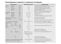
Сборник руководств по эксплуатации и техническому обслуживанию автомобиля SsangYong Kyron.
- Автор: —
- Издательство: SsangYong
- Год издания: —
- Страниц: —
- Формат: PDF
- Размер: 26,0 Mb
Руководство по эксплуатации, техническому обслуживанию и ремонту автомобиля SsangYong Kyron с 2005 года выпуска с дизельными двигателями объемом 2,0/2,7 л.
- Автор: —
- Издательство: Арго-Авто
- Год издания: —
- Страниц: 616
- Формат: —
- Размер: —


Рекомендуемые жидкости и смазочные материалы
Тип: Оригинальное моторное масло Ssangyong l
(отвечающее стандартам MB Sheet 229.1 или 229.3 или 229.31 —
для дизельных/бензиновых двигателей без CDPF)
(отвечающее стандартам MB Sheet 229.31 для дизельных
двигателей, оборудованных CDPF)
Вязкость: в соответствии со стандартом MB Sheet № 224.1
Оригинальная охлаждающая жидкость Ssangyong
Антифриз SYC-1025,
Антифриз : вода = 50 : 50
НА ОСНОВЕ ОРГАНИЧЕСКОЙ КИСЛОТЫ, ЦВЕТ: ГОЛУБОЙ
Оригинальная жидкость Ssangyong
(Shell ATF 134 или Fuchs ATF 134)
Оригинальная жидкость Ssangyong (FUCHS TITAN ATF 3292)
Оригинальная жидокость Ssangyong (ATF DEXRON II)
Оригинальная жидокость Ssangyong (ATF DEXRON II или III)
Оригинальное масло Ssangyong (SAE 80W/90, API GL-5)
Оригинальное масло Ssangyong
(Синтетическое масло Shell GL75W/90)
Оригинальное масло Ssangyong (SAE 80W/90, API GL-5)
Оригинальное масло Ssangyong
(Синтетическое масло Shell GL75W/90)
Оригинальная тормозная жидкость Ssangyong (DOT4)
Оригинальное масло Ssangyong (ATF DEXRON II или III)
* TOTAL FLUIDE DA или SHELL LHM-S
≒
7,5л
≒
8,5л
≒
7,5л
≒
9,0л
10,5 ~ 11,0л
11,0 ~ 11,5л
10,5 ~ 11,0л
11.5 ~ 12.0л
≒
8,0л
≒
9,5л
4WD: ≒ 3,6л, 2WD: ≒ 3,4л
≒
1,4л
≒
1,1л
≒
1,4л
≒
1,4л, ≒ 1,5л
≒
1,4л
≒
0,78л
МКП (D20DT, G23D) ≒ 1,9л
D27DT (ВСЕ), D20DT (АКП),
G23D (АКП) ≒ 2,0л
≒
1,8л
≒
1,5л
По мере необходимости
≒
1,0л
Моторное
масло
Охлаждающая
жидкость
Рабочая жидкость автоматической
коробки передач
Масло механической коробки передач
Масло раздаточной
коробки
Масло
редуктора
моста
Рабочая жидкость для гидропривода сцепления / тормоза
Жидкость гидроусилителя рулевого управления
Передний
Задний
Part Time
AWD
Без IOP
IOP
Неразрезной
LD
IRDA
Дизельный
двигатель
Бензиновый
двигатель
Дизельный
двигатель
Бензиновый
двигатель
Наименование
Заправочная емкость
D20DT
D27DT
G23D
G32D
D20DT
D27DT
G23D
G32D
DC5
6-ступ. АКП
D20DT
D27DT
G23D
Спецификации
ssangyong-rs.ru ® Все права защищены.
© 1997 — 2018 «АЛЬФА — Сервис» — официальный дилер SsangYong (Sollers) в России: SsangYong Actyon, SsangYong Kyron, SsangYong Actyon Sports.
Вся информация, предоставленная на сайте, публичной офертой не является.
Правовая информация