Информация, представленная на Сайте, носит информационный характер и ни при каких условиях не является публичной
офертой, определяемой положениями статьи 437 Гражданского кодекса Российской Федерации. Все содержащиеся на
Сайте сведения носят исключительно информационный характер и не являются исчерпывающими. Все условия
приобретения мототехники, цены, спецпредложения и комлектации мототехники указаны с целью ознакомления.
Комплектации и цены действительны на момент публикации и могут быть изменены без предварительного оповещения.
Представленная на Сайте мототехника может быть укомплектована дополнительным оборудованием, не входящим в
стандартную версию, но доступным за дополнительную плату. Сведения о продукции, касающиеся объёмов поставки,
внешнего вида, характеристик, габаритов и веса, эксплуатационных затрат и т.д. не являются обязательными,
рассматриваются как приблизительные и указаны с условием того, что могут возникнуть ошибки при печати, настройке
и/или наборе текста. Такая информация может быть изменена без предварительного уведомления. Чтобы получить
полную информацию о продукции, услугах, дополнительном оборудовании и спецпредложениях, интересных для Вас,
обращайтесь к менеджерам Дилерского центра
- Manuals
- Brands
- KTM Manuals
- Motorcycle
- 250 EXC
Manuals and User Guides for KTM 250 EXC. We have 13 KTM 250 EXC manuals available for free PDF download: Owner’s Manual, Repair Manual, Owner’s Handbook Manual, Manual

KTM 250 EXC Owner’s Manual (410 pages)
Brand: KTM
|
Category: Motorcycle
|
Size: 23.71 MB
Table of Contents
-
Table of Contents
5
-
Important Limited Warranty and Limited Guarantee Information
4
-
Table of Contents
5
-
-
Engine Number, Engine Type
6
-
Serial Number Locations
6
-
Chassis Number
6
-
Operation Instruments
7
-
Clutch Lever
7
-
Hand Decompression Lever
7
-
Hand Brake Lever
7
-
Combination Switch (EXC)
7
-
Short Circuit Button (SX/MXC)
7
-
Flasher Switch
8
-
Starter Button (EXC)
8
-
Emergency off Switch (EXC Australia)
8
-
Digital Speedometer, Indicator Lamps
8
-
Electronic Speedometer
9
-
Setting the Clock
13
-
Overview of Electronic Speedometer Functions
13
-
-
Hot Start Device (450/525 SX)
14
-
Filler Cap
14
-
Choke
14
-
Fuel Tap
14
-
Shift Lever
15
-
Kickstarter
15
-
Foot Brake Pedal
15
-
Side Stand
15
-
Steering Lock
15
-
Compression Damping of Fork
16
-
Rebound Damping of Fork
16
-
Damping Action During Compression of Shock Absorber (SX)
16
-
Compression Damping of Shock Absorber (MXC, EXC)
17
-
Rebound Damping of Shock Absorber (SX, MXC, EXC)
17
-
General Tips and Warnings for Starting the Motorcycle
18
-
Instructions for Initial Operation
18
-
Running in the Racing Models
18
-
Driving Instructions
19
-
Check the Following before each Start
19
-
Starting When the Engine Is Warm
20
-
What to Do When the Engine Is «Flooded
20
-
Starting off
20
-
Shifting/Riding
20
-
Starting When the Engine Is Cold
20
-
Braking
21
-
Stopping and Parking
21
-
Fuel
21
-
Periodic Maintenance
22
-
Maintenance Work on Chassis and Engine
26
-
Changing the Spring Preloading of the Shock Absorber
26
-
Pivot Bearing
26
-
Determining the Static Sag of the Shock Absorber
27
-
Determining the Riding Sag of the Shock Absorber
27
-
Checking the Shock Absorber and Spring
27
-
Basic Suspension Setup for the Weight of the Driver
27
-
Checking the Basic Setup of the Telescopic Fork
28
-
Changing the Spring Preload on the Telescopic Fork (SX Models)
28
-
Changing the Spring Preload on the Telescopic Fork (MXC/EXC Models)
28
-
Replacing Fork Springs
28
-
Checking and Adjusting the Steering Head Bearing
29
-
Cleaning the Dust Sleeves of the Telescopic Fork
29
-
Breather Plug Front Fork
29
-
Changing the Fork Offset (Caster) (SX)
30
-
Checking and Adjusting the Steering Head Bearing
31
-
Check Chain Tension
32
-
Correct Chain Tension
32
-
Chain Maintenance
33
-
Chain Wear
33
-
General Information about KTM Disc Brakes
34
-
Checking the Front Brake Pads
35
-
Refilling the Front Brake Fluid Reservoir
35
-
Checking the Brake Fluid Level — Front Brake
35
-
Adjusting the Free Travel at the Hand Brake Lever
35
-
Replacing the Front Brake Pads
36
-
Changing the Basic Position of the Foot Brake Pedal
36
-
Checking the Rear Brake Fluid Level
36
-
Refilling the Rear Brake Fluid Reservoir
36
-
Checking the Rear Brake Pads
37
-
Replacing the Rear Brake Pads
37
-
Dismounting and Mounting the Front Wheel
37
-
Dismounting and Mounting the Rear Wheel
38
-
Checking Spoke Tension
38
-
Tires, Air Pressure
39
-
Check/Set Distance of the Magnetic Sensor
39
-
Replacing the Battery of the Digital Speedometer
39
-
Battery (MXC/EXC)
40
-
Charging the Battery
40
-
Fuse (MXC/EXC)
41
-
Replacing Headlight Lamp/Parking Light Lamp
41
-
Cooling System
42
-
Checking the Coolant Level
42
-
Bleeding the Cooling System
42
-
Replacing the Glassfiber Yarn Packing of the Silencer
43
-
Cleaning the Spark Arrester (MXC/EXC USA)
43
-
Cleaning the Air Filter
44
-
Checking the Adjustment of the Hand Decompression Release Cable
44
-
Adjusting the Throttle Cables
44
-
Changing the Original Position of the Clutch Lever
45
-
Checking the Oil Level of the Hydraulic Clutch
45
-
Bleeding of the Hydraulic Clutch
45
-
CARBURETOR — Adjust Idling (Keihin-FCRMX 37/39/41)
46
-
Adjusting the Mixture Control Screw
46
-
Checking the Float Level (Float Height)
46
-
Checking the Engine Oil Level
47
-
Oil Circuit
47
-
Draining the Float Chamber of the Carburetor
47
-
Engine Oil
48
-
Changing the Engine Oil
48
-
Changing Oil Filters
49
-
-
Troubleshooting
50
-
Storage
52
-
Conservation for Winter Operation
52
-
Use after a Period of Storage
52
-
Cleaning
52
-
Technical Data — Engine
53
-
Technical Data — Chassis
56
-
Cylinder Head
127
-
Checking Charging Voltage
162
-
Ignition Coil
163
-
Troubleshooting in Ignition System
163
-
Basic Carburator Setting
207
-
-
Advertisement

KTM 250 EXC Owner’s Manual (154 pages)
Brand: KTM
|
Category: Motorcycle
|
Size: 7.42 MB
Table of Contents
-
Table of Contents
4
-
1 Means of Representation
7
-
Symbols Used
7
-
Formats Used
7
-
-
2 Safety Advice
8
-
Use Definition — Intended Use
8
-
Degrees of Risk and Symbols
8
-
Tampering Warning
8
-
Safe Operation
9
-
Protective Clothing
9
-
Work Rules
9
-
Environment
9
-
Owner’s Manual
9
-
-
3 Important Notes
10
-
Guarantee, Warranty
10
-
Operating and Auxiliary Substances
10
-
Spare Parts, Accessories
10
-
Service
10
-
Figures
10
-
Customer Service
10
-
-
4 View of Vehicle
11
-
View of Vehicle, Front Left (Example)
11
-
View of Vehicle, Rear Right (Example)
12
-
-
5 Serial Numbers
13
-
Chassis Number
13
-
Type Label
13
-
Key Number (All EXC Models)
13
-
Engine Number
13
-
Fork Part Number
13
-
Shock Absorber Part Number
14
-
-
6 Controls
15
-
Clutch Lever
15
-
Hand Brake Lever
15
-
Throttle Grip
15
-
Kill Switch (All EXC Models)
15
-
Kill Switch (All XC-W Models)
16
-
Horn Button (All EXC Models)
16
-
Light Switch (All EXC Models)
16
-
Light Switch (All XC-W Models)
16
-
Turn Signal Switch (All EXC Models)
16
-
Emergency off Switch (EXC AU)
17
-
Electric Starter Button (All 200/250/300 EU/US Models, 300 EXC BR)
17
-
Electric Starter Button (EXC AU)
17
-
Overview of Indicator Lamps (All EXC Models)
17
-
Overview of Indicator Lamps (All XC-W Models)
17
-
Opening the Filler Cap
18
-
Closing the Filler Cap
18
-
Fuel Tap
19
-
Choke
19
-
Shift Lever
19
-
Kick Starter
20
-
Foot Brake Lever
20
-
Side Stand
20
-
Steering Lock (All EXC Models)
20
-
Locking the Steering (All EXC Models)
21
-
Unlocking the Steering (All EXC Models)
21
-
-
7 Speedometer
22
-
Speedometer Overview
22
-
Activation and Test
22
-
Setting Kilometers or Miles
22
-
Setting the Speedometer Functions
23
-
Setting the Clock
23
-
Viewing the Lap Time
23
-
Display Mode SPEED (Speed)
24
-
Display Mode SPEED/H (Service Hours)
24
-
Setup Menu
25
-
Setting the Unit of Measurement
25
-
Display Mode SPEED/CLK (Time)
26
-
Setting the Clock
26
-
Display Mode SPEED/LAP (Lap Time)
26
-
Viewing the Lap Time
27
-
Display Mode SPEED/ODO (Odometer)
27
-
Display Mode SPEED/TR1 (Trip Master 1)
27
-
Display Mode SPEED/TR2 (Trip Master 2)
28
-
Setting TR2 (Trip Master 2)
28
-
Display Mode SPEED/A1 (Average Speed 1)
28
-
Display Mode SPEED/A2 (Average Speed 2)
29
-
Display Mode SPEED/S1 (Stop Watch 1)
29
-
Display Mode SPEED/S2 (Stop Watch 2)
29
-
Table of Functions
30
-
Table of Conditions and Menu Activation
31
-
-
8 Preparing for Use
32
-
Advice on First Use
32
-
Running in the Engine
33
-
Preparing the Vehicle for Difficult Riding Conditions
33
-
Preparations for Riding on Dry Sand
34
-
Preparations for Riding on Wet Sand
34
-
Preparations for Riding on Wet and Muddy Surfaces
35
-
Preparations for Riding at High Temperatures and Low Speeds
35
-
Preparing for Riding at Low Temperatures or in Snow
36
-
-
9 Riding Instructions
37
-
Checks and Maintenance Work When Preparing for Use
37
-
Starting
37
-
Start off
38
-
Shifting, Riding
38
-
Braking
38
-
Stopping, Parking
39
-
Transport
39
-
Refueling
40
-
-
10 Service Schedule
41
-
Service Work (as Additional Order)
42
-
-
11 Tuning the Chassis
43
-
Checking the Basic Chassis Setting with the Rider’s Weight
43
-
Compression Damping of Shock Absorber
43
-
Adjusting the Low-Speed Compression Damping of the Shock Absorber
43
-
Adjusting the High-Speed Compression Damping of the Shock Absorber
44
-
Adjusting the Rebound Damping of the Shock Absorber
44
-
Measuring the Sag of the Unloaded Rear Wheel
45
-
Checking the Static Sag of the Shock Absorber
45
-
Checking the Riding Sag of the Shock Absorber
46
-
Adjusting the Spring Preload of the Shock Absorber
46
-
Adjusting the Riding Sag
47
-
Checking the Basic Setting of the Fork
47
-
Adjusting the Compression Damping of the Fork
48
-
Adjusting the Rebound Damping of the Fork
49
-
Adjusting the Spring Preload of the Fork (EXC, XC-W)
50
-
Handlebar Position
51
-
Adjusting the Handlebar Position
52
-
-
12 Service Work on the Chassis
54
-
Raising the Motorcycle with the Lift Stand
54
-
Removing the Motorcycle from the Lift Stand
54
-
Bleeding the Fork Legs
54
-
Cleaning the Dust Boots of the Fork Legs
55
-
Removing the Fork Protector
55
-
Installing the Fork Protector
56
-
Removing the Fork Legs
56
-
Installing the Fork Legs
57
-
Removing the Lower Triple Clamp (200 XC-W US, 250 XC-W US, 300 EXC BR, 300 XC-W US)
58
-
Removing the Lower Triple Clamp (EXC EU, EXC Six Days, EXC EU/AU, Six Days)
59
-
Installing the Lower Triple Clamp
59
-
(200 XC-W Us, 250 XC-W Us, 300 Exc Br, 300 XC-W Us)
59
-
Installing the Lower Triple Clamp (EXC EU, EXC Six Days, EXC EU/AU, Six Days)
61
-
Checking the Play of the Steering Head Bearing
64
-
Adjusting the Play of the Steering Head Bearing
65
-
Greasing the Steering Head Bearing
66
-
Removing the Front Fender
66
-
Installing the Front Fender
67
-
Removing the Shock Absorber
67
-
Installing the Shock Absorber
67
-
Removing the Seat
68
-
Mounting the Seat
68
-
Removing the Air Filter Box Lid
69
-
Installing the Air Filter Box Lid
69
-
Removing the Air Filter
69
-
Installing the Air Filter
70
-
Cleaning the Air Filter and Air Filter Box
70
-
Sealing the Air Filter Box
71
-
Removing the Main Silencer
71
-
Installing the Main Silencer
71
-
Changing the Glass Fiber Yarn Filling of the Main Silencer
71
-
Removing the Fuel Tank
72
-
Installing the Fuel Tank
73
-
Checking the Chain for Dirt
74
-
Cleaning the Chain
74
-
Checking the Chain Tension
74
-
Adjusting the Chain Tension
75
-
Checking the Chain, Rear Sprocket, Engine Sprocket and Chain Guide
76
-
Checking the Frame
77
-
Checking the Swingarm
78
-
Checking the Routing of the Throttle Cable
78
-
Checking the Rubber Grip
79
-
Additionally Securing the Rubber Grip
79
-
Adjusting the Basic Position of the Clutch Lever
79
-
Checking/Correcting the Fluid Level of the Hydraulic Clutch
80
-
Changing the Hydraulic Clutch Fluid
80
-
Removing the Engine Guard
82
-
Installing the Engine Guard
82
-

KTM 250 EXC Owner’s Manual (145 pages)
Brand: KTM
|
Category: Motorcycle
|
Size: 7.05 MB
Table of Contents
-
Table of Contents
4
-
Table of Contents 2
4
-
1 Means of Representation
7
-
Symbols Used
7
-
Formats Used
7
-
-
2 Safety Advice
8
-
Use Definition — Intended Use
8
-
Degrees of Risk and Symbols
8
-
Tampering Warning
8
-
Safe Operation
9
-
Protective Clothing
9
-
Work Rules
9
-
Environment
9
-
Owner’s Manual
9
-
-
3 Important Notes
10
-
Guarantee, Warranty
10
-
Operating and Auxiliary Substances
10
-
Spare Parts, Accessories
10
-
Service
10
-
Figures
10
-
Customer Service
10
-
-
4 View of Vehicle
11
-
View of Vehicle, Front Left (Example)
11
-
View of Vehicle, Rear Right (Example)
12
-
-
5 Serial Numbers
13
-
Chassis Number
13
-
Type Label
13
-
Key Number (All EXC Models)
13
-
Engine Number
13
-
Fork Part Number
13
-
Shock Absorber Part Number
14
-
-
6 Controls
15
-
Clutch Lever
15
-
Hand Brake Lever
15
-
Throttle Grip
15
-
Kill Switch (EXC EU/AU, EXC Factory Edition, 300 EXC BR)
15
-
Kill Switch (Six Days EU)
16
-
Kill Switch (All XC-W Models)
16
-
Horn Button (EXC EU/AU, EXC Factory Edition, 300 EXC BR)
16
-
Horn Button (Six Days EU)
16
-
Light Switch (EXC EU/AU, EXC Factory Edition, 300 EXC BR)
16
-
Light Switch (Six Days EU)
17
-
Light Switch (All XC-W Models)
17
-
Turn Signal Switch (EXC EU/AU, EXC Factory Edition, 300 EXC BR)
17
-
Turn Signal Switch (Six Days EU)
17
-
Emergency off Switch (EXC AU)
17
-
Electric Starter Button (All 200/250/300 EU/US Models, 300 EXC BR)
18
-
Electric Starter Button (EXC AU)
18
-
Overview of Indicator Lamps (All EXC Models)
18
-
Overview of Indicator Lamps (All XC-W Models)
18
-
Opening the Filler Cap
18
-
Closing the Filler Cap
19
-
Fuel Tap
19
-
Choke
20
-
Shift Lever
20
-
Kick Starter
20
-
Foot Brake Lever
20
-
Side Stand
21
-
Steering Lock (All EXC Models)
21
-
Locking the Steering (All EXC Models)
21
-
Unlocking the Steering (All EXC Models)
22
-
-
7 Speedometer
23
-
Speedometer Overview
23
-
Activation and Test
23
-
Setting Kilometers or Miles
23
-
Setting the Speedometer Functions
24
-
Setting the Clock
24
-
Viewing the Lap Time
24
-
Display Mode SPEED (Speed)
25
-
Display Mode SPEED/H (Service Hours)
25
-
Setup Menu
25
-
Setting the Unit of Measurement
26
-
Display Mode SPEED/CLK (Time)
26
-
Setting the Clock
27
-
Display Mode SPEED/LAP (Lap Time)
27
-
Viewing the Lap Time
27
-
Display Mode SPEED/ODO (Odometer)
28
-
Display Mode SPEED/TR1 (Trip Master 1)
28
-
Display Mode SPEED/TR2 (Trip Master 2)
28
-
Setting TR2 (Trip Master 2)
28
-
Display Mode SPEED/A1 (Average Speed 1)
29
-
Display Mode SPEED/A2 (Average Speed 2)
29
-
Display Mode SPEED/S1 (Stop Watch 1)
30
-
Display Mode SPEED/S2 (Stop Watch 2)
30
-
Table of Functions
30
-
Table of Conditions and Menu Activation
31
-
-
8 Preparing for Use
32
-
Advice on First Use
32
-
Running in the Engine
33
-
Preparing the Vehicle for Difficult Riding Conditions
33
-
Preparations for Riding on Dry Sand
34
-
Preparations for Riding on Wet Sand
34
-
Preparations for Riding on Wet and Muddy Surfaces
35
-
Preparations for Riding at High Temperatures and Low Speeds
35
-
Preparing for Riding at Low Temperatures or in Snow
36
-
-
9 Riding Instructions
37
-
Checks and Maintenance Work When Preparing for Use
37
-
Starting
37
-
Start off
38
-
Shifting, Riding
38
-
Braking
38
-
Stopping, Parking
39
-
Transport
39
-
Refueling
40
-
-
10 Service Schedule
41
-
Service Work (as Additional Order)
42
-
-
11 Tuning the Chassis
43
-
Checking the Basic Chassis Setting with the Rider’s Weight
43
-
Compression Damping of Shock Absorber
43
-
Adjusting the Low-Speed Compression Damping of the Shock Absorber
43
-
Adjusting the High-Speed Compression Damping of the Shock Absorber
44
-
Adjusting the Rebound Damping of the Shock Absorber
44
-
Measuring the Sag of the Unloaded Rear Wheel
45
-
Checking the Static Sag of the Shock Absorber
45
-
Checking the Riding Sag of the Shock Absorber
46
-
Adjusting the Spring Preload of the Shock Absorber
46
-
Adjusting the Riding Sag
47
-
Checking the Basic Setting of the Fork
47
-
Adjusting the Compression Damping of the Fork
48
-
Adjusting the Rebound Damping of the Fork
49
-
Adjusting the Spring Preload of the Fork (EXC, XC-W, EXC Factory Edition)
50
-
Handlebar Position
50
-
Adjusting the Handlebar Position
51
-
Advertisement
KTM 250 EXC Repair Manual (154 pages)
KTM Automobile Parts User Manual
Brand: KTM
|
Category: Engine
|
Size: 5.51 MB
Table of Contents
-
Table of Contents
5
-
Updating Instructions
7
-
Explanation — Updating
9
-
General Information
14
-
Operating Ranges of the Carburetor
16
-
Basic Information on a Change of the Carburetor Setting
17
-
Basic Information on the Original Carburetor Setting
17
-
-
Carburetor Adjustment
17
-
Bleeding of the Hydraulic Clutch
18
-
Checking the Setting of the TVC System
18
-
Special Tools — Engine 250/300/380
19
-
-
Cleaning
20
-
Conservartion for Winter Operation
20
-
Storage
20
-
Removing and Refitting Engine
22
-
Dismounting the Engine
24
-
Filling in of Cooling Liquid
26
-
Filling in of Transmission Oil
26
-
Refitting the Engine
26
-
-
Disassembling the Engine
28
-
Dismounting of Cylinder Head, Cylinder and Piston
30
-
Dismounting of Sprocket and Shift Lever
30
-
Draining Gear Oil
30
-
Dismounting of Clutch Cover
31
-
Dismounting of Pressure Cap and Clutch Discs
32
-
Dismounting of the Primary Drive
32
-
Dismounting of Ignition Cover
33
-
Dismounting of Kickstarter
33
-
Dismounting of the Shift Lock
33
-
Dismounting of the Ignition (Kokusan)
34
-
Dismounting of the Ignition (SEM)
34
-
Dismounting of Gearshift Mechanism and Transmission
35
-
Dismounting of Intake Flange and Reed Valve Housing
35
-
Parting of Engine Housing Halves
35
-
Dismounting the Crankshaft
36
-
Servicing of Individual Components
37
-
Working on the Right-Hand Housing Half
39
-
Working on the Left-Hand Housing Half
40
-
-
Crankshaft
41
-
Crankshaft Webs – Measure Outer Dimension
41
-
Piston
41
-
Piston Ring End Gap
41
-
Checking Cylinder for Wear
42
-
Nikasil Coating of Cylinder
42
-
Recoated Cylinder
42
-
Cylinder Exhaust Control System
43
-
Cylinder Preassembly
43
-
Exhaust Control, Clutch Cover
45
-
Preassembly of Clutch Cover
45
-
Reed Valve Housing, Intake Flange
46
-
Clutch
47
-
Replace Outer Clutch Hub
48
-
Preassembly of Shift Shaft
49
-
Shift Mechanism
49
-
Check Stator and Pulse Generator (Kokusan)
50
-
Ignition (Kokusan)
50
-
Kokusan Ignition & Spark Plug
50
-
Check Stator (SEM)
51
-
Ignition (SEM)
51
-
SEM Ignition & Spark Plug
51
-
Assembly Mainshaft
52
-
Transmission
52
-
Assembly Countershaft
53
-
Assemble of Kickstarter Shaft
54
-
Assembling the Engine
55
-
Assembling the Engine Housing
58
-
Mounting Kickstarter
59
-
Mounting Shift Mechanism
59
-
Mount Primary Drive and Clutch
60
-
Mounting Clutch Discs and Pressure Cap
61
-
Adjusting Dimension „X“
62
-
Mounting Piston and Cylinder
62
-
Adjusting Control Flap (Dimension “Z“)
63
-
Mounting Cylinder Head
64
-
Mounting Reed Valve Housing and Intake Flange
64
-
Mounting Steering Covers
64
-
Mounting Engine Sprocket
65
-
Mounting the Ignition (Kokusan)
65
-
Adjusting Ignition Point (SEM)
66
-
Mounting Starting Lever and Shift Lever
66
-
Mounting the Ignition (SEM)
66
-
Electrical
67
-
Checking the Voltage Regulator (Kokusan)
69
-
Checking the Voltage Regulator (Tympanium)
69
-
Checking the Voltage Regulator-Rectifier (Shindengen)
69
-
CDI Unit
70
-
Checking the Capacitor
70
-
Ignition Coil (Kokusan)
70
-
Ignition Coil (SEM)
70
-
Checking the Voltage Regulator
71
-
Static Ignition Values 250-380 SX, EXC (Kokusan 2K-1, 2K-3, 2K-4)
72
-
Static Generator Values 250-380 EXC (Kokusan 2K-3) (Except 250 USA)
74
-
Static Ignition Values 250 MXC, EXC USA (Kokusan 2K-2)
76
-
Troubleshooting
79
-
-
Trouble Shooting
81
-
Technical Specifications
83
-
Technical Specifications — Engine 250/300/380 SX/MXC/EXC ‘99 (Only for USA)
85
-
Basic Carburetor Setting
86
-
Gasket Thicknesses
86
-
Tightening Torques
86
-
Tolerances and Fitting Clearances
86
-
Technical Specifications — Engine 250/300/380 SX/EXC/EGS ‘99 (All Models out of USA)
87
-
Standard Adjustment — Fork
89
-
Standard Adjustment — Shock Absorber
89
-
Technical Specifications Chassis 250/300/380 SX/MXC/EXC/EGS ‘99
89
-
Carburetor Setting KTM 250/300 MXC/EXC EU, USA‘99 KEIHIN PWK 38
90
-
Carburetor Setting KTM 250 SX Europe, USA ‘99 KEIHIN PWK 38
91
-
Carburetor Setting KTM 380 SX/MXC/EXC EU, USA ‘99 KEIHIN PWK 38
92
-
Technical Data — Engine 250/300/380 SX/MXC/EXC 2000 (Only USA)
93
-
Technical Data — Engine 250/300/380 SX/EXC 2000 (All Models out of USA)
95
-
Technical Specifications Chassis 250/300/380 SX, MXC, EXC 2000
97
-
Carburetor Setting G KTM 250 SX EUR/USA 2000 KEIHIN PWK 38AG PJ
98
-
Carburetor Setting KTM 250 MXC/EXC EUR/USA 2000 KEIHIN PWK 38 AG
99
-
Carburetor Setting KTM 300 MXC/EXC EUR/USA 2000 KEIHIN PWK 38 AG
100
-
Carburetor Setting KTM 380 SX/MXC/ EXC/EUR/USA 2000 KEIHIN PWK 38 AG
101
-
Technical Data — Engine 250/300/380 SX/MXC EXC 2001 (Only USA)
103
-
Technical Data — Engine 250/300/380 SX / EXC 2001 (All Models out of USA)
105
-
Technical Specifications Chassis 250/300/380 SX, MXC, EXC 2001
107
-
Carburetor Setting KTM 250 SX EUR/USA 2001 KEIHIN PWK 38AG PJ
108
-
Carburetor Setting KTM 250 MXC/EXC EUR/USA 2001 KEIHIN PWK 38 AG
109
-
Carburetor Setting KTM 300 MXC/EXC EUR/USA 2001 KEIHIN PWK 38 AG
110
-
Carburetor Setting KTM 380 SX / MXC / EXC EUR / USA 2001 KEIHIN PWK 38 AG
111
-
Technical Data — Engine 250/300/380 SX / MXC / EXC 2002 (Only USA)
112
-
Technical Data — Engine 250/300/380 SX / EXC 2002 (All Models out of USA)
114
-
Technical Specifications Chassis 250/300/380 SX, MXC, EXC 2002
116
-
Carburetor Setting KTM 250 SX EUR/USA 2002 KEIHIN PWK 38AG
117
-
Carburetor Setting KTM 250 MXC/EXC EUR/USA 2002 KEIHIN PWK 38 AG
118
-
Carburetor Setting KTM 300 MXC/EXC EUR/USA 2002 KEIHIN PWK 38 AG
119
-
Carburetor Setting KTM 380 SX / MXC / EXC EUR / USA 2002 KEIHIN PWK 38 AG
120
-
Technical Data — Engine 250/300 MXC/EXC 2003
121
-
Periodic Lubrication and Maintenance Schedule
131
-
Periodic Maintenance Schedule 2001/02
132
-
Important Chacks and Maintenance to be Carried by the Rider
133
-
Periodic Maintenance Schedule 2003
134
-
Recommended Inspection of the 250/300 EXC and MXC Engine Used for Enduro Competitions by Your KTM Workshop
136
-
Recommended Inspection of the 250/300 EXC and MXC Engine Used for Hobby Enduro by Your KTM Workshop
136
-
-

KTM 250 EXC Owner’s Manual (70 pages)
KTM Owner’s Manual Motorcycle 250 SX-F, 250 EXC, 400 EXC, 450 SX, XC, EXC, 525 SX, XC
Brand: KTM
|
Category: Motorcycle
|
Size: 5.62 MB
Table of Contents
-
Important Limited Warranty and Limited Guarantee Information
4
-
Table of Contents
5
-
Serial Number Locations
6
-
Chassis Number
6
-
Engine Number, Engine Type
6
-
-
Operation Instruments
6
-
Clutch Lever
6
-
Hot Start Lever (250 SX-F)
7
-
Hand Decompression Lever (450/525 SX)
7
-
Hand Brake Lever
7
-
Short Circuit Button (SX/XC)
7
-
Combination Switch (EXC)
7
-
Flasher Switch
8
-
Starter Button (EXC)
8
-
Emergency off Switch (EXC Australia)
8
-
Indicator Lamps
8
-
Electronic Speedometer
9
-
Setting the Clock
13
-
Filler Cap
13
-
Overview of Electronic Speedometer Functions
13
-
Fuel Tap
14
-
Choke
14
-
Hot Start Device (450/525 SX)
14
-
Shift Lever
15
-
Kickstarter
15
-
Foot Brake Pedal
15
-
Side Stand
15
-
Steering Lock
15
-
Compression Damping of Fork
16
-
Rebound Damping of Fork
16
-
Damping Action During Compression of Shock Absorber (SX)
16
-
Compression Damping of Shock Absorber (XC, EXC)
17
-
Rebound Damping of Shock Absorber (SX, XC, EXC)
17
-
-
General Tips and Warnings for Starting the Motorcycle
18
-
Instructions for Initial Operation
18
-
Running in the Racing Models
18
-
-
Driving Instructions
19
-
Check the Following before each Start
19
-
Starting When the Engine Is Cold
19
-
Starting When the Engine Is Warm
20
-
What to Do When the Engine Is „Flooded
20
-
Starting off
20
-
Shifting/Riding
20
-
Braking
21
-
Stopping and Parking
21
-
Fuel
21
-
-
Periodic Maintenance
22
-
Maintenance Work on Chassis and Engine
28
-
Changing the Spring Preloading of the Shock Absorber
28
-
Pivot Bearing
28
-
Basic Suspension Setup for the Weight of the Driver
29
-
Checking the Shock Absorber and Spring
29
-
Determining the Static Sag of the Shock Absorber
29
-
Determining the Riding Sag of the Shock Absorber
29
-
Checking the Basic Setup of the Telescopic Fork
30
-
Changing the Spring Preload on the Telescopic Fork (SX Models)
30
-
Changing the Spring Preload on the Telescopic Fork (XC/EXC Models)
30
-
Replacing Fork Springs
30
-
Breather Plug Front Fork
31
-
Cleaning the Dust Sleeves of the Telescopic Fork
31
-
Checking and Adjusting the Steering Head Bearing
31
-
Changing the Fork Offset (Caster) (SX)
32
-
Checking and Adjusting the Steering Head Bearing
33
-
Check Chain Tension
34
-
Correct Chain Tension
34
-
Chain Maintenance
35
-
Chain Wear
35
-
General Information about KTM Disc Brakes
36
-
Adjusting the Free Travel at the Hand Brake Lever
37
-
Checking the Brake Fluid Level — Front Brake
37
-
Refilling the Front Brake Fluid Reservoir
37
-
Checking the Front Brake Pads
37
-
Replacing the Front Brake Pads
38
-
Changing the Basic Position of the Foot Brake Pedal
38
-
Checking the Rear Brake Fluid Level
38
-
Refilling the Rear Brake Fluid Reservoir
38
-
Checking the Rear Brake Pads
39
-
Replacing the Rear Brake Pads
39
-
Dismounting and Mounting the Front Wheel
39
-
Dismounting and Mounting the Rear Wheel
40
-
Checking Spoke Tension
40
-
Tires, Air Pressure
41
-
Check/Set Distance of the Magnetic Sensor
41
-
Replacing the Battery of the Digital Speedometer
41
-
Battery (XC/EXC)
42
-
Charging the Battery
42
-
Fuse (XC/EXC)
43
-
Replacing Headlight Lamp/Parking Light Lamp
43
-
Cooling System
44
-
Checking the Coolant Level
44
-
Bleeding the Cooling System
44
-
Replacing the Glassfiber Yarn Packing of the Silencer
45
-
Cleaning the Spark Arrester (XC/EXC USA)
45
-
Cleaning the Air Filter
46
-
Checking the Adjustment of the Hand Decompression Release Cable
46
-
Adjusting the Throttle Cables
46
-
Changing the Original Position of the Clutch Lever
47
-
Checking the Oil Level of the Hydraulic Clutch
47
-
Bleeding of the Hydraulic Clutch
47
-
Carburetor — Adjust Idling (Keihin-FCRMX 37/39/41)
48
-
Adjusting the Mixture Control Screw
48
-
Checking the Float Level (Float Height)
48
-
Draining the Float Chamber of the Carburetor
49
-
Oil Circuit
49
-
Checking the Engine Oil Level
49
-
Engine Oil
50
-
Changing the Engine Oil
50
-
Changing the Oil Filters
51
-

KTM 250 EXC Owner’s Manual (74 pages)
KTM Owner’s Manual Motorcycle 125 EXC, EXC SIX DAYS 200 XC, XC-W, EXC 250 XC, XC-W, EXC, EXC SIX DAYS 300 XC, XC-W, EXC-E, EXC-E SIX DAYS
Brand: KTM
|
Category: Motorcycle
|
Size: 9.08 MB
Table of Contents
-
Table of Contents
5
-
Serial Number Locations
6
-
Chassis Number
6
-
Engine Number, Engine Type
6
-
-
Operation Instruments
6
-
Clutch Lever
6
-
Hand Brake Lever
6
-
Electronic Speedometer
7
-
Indicator Lamps (EXC)
11
-
Short Circuit Button
11
-
Combination Switch (EXC)
12
-
Headlamp Switch (XC-W)
12
-
Flasher Switch
12
-
Starter Button
12
-
Emergency off Switch (Australia)
12
-
Filler Cap
13
-
Fuel Tap
13
-
Choke Knob
13
-
Shift Lever
14
-
Kickstarter
14
-
Foot Brake Pedal
14
-
Side Stand
14
-
Steering Lock
14
-
Compression Damping of Fork
15
-
Rebound Damping of Fork
15
-
Spring Preload of the Fork
15
-
Shock Absorber Compression Damping
16
-
Shock Absorber Rebound Damping
16
-
-
General Tips and Warnings for Starting the Motorcycle
17
-
Instructions for Your First Ride
17
-
Running in
17
-
-
Driving Instructions
18
-
What You Should Check before each Start
18
-
Starting When the Engine Is Cold
19
-
Starting When the Engine Is Warm
19
-
What to Do When the Engine Is „Flooded
19
-
Starting off
19
-
Shifting/Riding
20
-
Braking
20
-
Stopping and Parking
20
-
Refueling, Fuel
20
-
-
Periodic Maintenance Schedule
21
-
Maintenance Work on Chassis and Engine
25
-
Changing the Spring Preloading of the Shock Absorber
25
-
Pivot Bearing
25
-
Basic Suspension Setup for the Weight of the Driver
26
-
Checking the Shock Absorber and Spring
26
-
Determining the Static Sag of the Shock Absorber
26
-
Determining the Riding Sag of the Shock Absorber
26
-
Changing the Spring Preload on the Telescopic Fork
27
-
Checking the Basic Setup of the Telescopic Fork
27
-
Breather Plug Front Fork
27
-
Cleaning the Dust Sleeves of the Telescopic Fork
28
-
Checking and Adjusting the Steering Head Bearing
28
-
Changing the Fork Offset (Caster) XC/EXC Six Days
29
-
How to Change the Handlebar Position
30
-
Adapting Chain Guide to the Rear Sprocket
31
-
Check Chain Tension
32
-
Correct Chain Tension
32
-
Chain Maintenance
32
-
Chain Wear
32
-
General Information about KTM Disc Brakes
33
-
Changing Basic Position of the Hand Brake Lever
34
-
Checking the Brake Fluid Level — Front Brake
34
-
Refilling the Front Brake Fluid Reservoir
34
-
Checking the Front Brake Pads
34
-
Replacing the Front Brake Pads
35
-
Checking the Rear Brake Fluid Level
35
-
Refilling the Rear Brake Fluid Reservoir
35
-
Changing the Basic Position of the Foot Brake Pedal
36
-
Checking the Rear Brake Pads
36
-
Replacing the Rear Brake Pads
36
-
Dismounting and Mounting the Front Wheel
37
-
Dismounting and Mounting the Rear Wheel
38
-
Tires, Air Pressure
38
-
Checking Spoke Tension
39
-
Replacing the Battery of the Digital Speedometer
39
-
Replacing the Headlight Lamp/Parking Light Lamp
39
-
Battery
40
-
Charging the Battery
40
-
Fuse
41
-
Cooling System
41
-
Checking the Coolant Level
42
-
Refilling/Bleeding the Cooling System
42
-
Cleaning the Air Filter
42
-
Checking the Oil Level of the Hydraulic Clutch
43
-
Exhaust System
43
-
Changing the Original Position of the Clutch Lever
43
-
Bleeding the Hydraulic Clutch
44
-
Carburetor Adjustment
44
-
Draining the Float Chamber of the Carburetor
46
-
Checking the Float Level
46
-
Adjusting the Engine Characteristic Via the Ignition Curve
46
-
Adjusting the Engine Characteristic Via the Auxiliary Spring
47
-
Check Transmission Oil Level
48
-
Changing the Transmission Oil
48
-

KTM 250 EXC Owner’s Manual (71 pages)
2007
Brand: KTM
|
Category: Motorcycle
|
Size: 5.14 MB
Table of Contents
-
Table of Contents
5
-
Serial Number Locations
6
-
Chassis Number
6
-
Engine Number, Engine Type
6
-
-
Operation Instruments
6
-
Clutch Lever
6
-
Hand Brake Lever
6
-
Electronic Speedometer
7
-
Indicator Lamps (EXC)
11
-
Combination Switch (EXC)
12
-
Headlamp Switch (XC-W)
12
-
Flasher Switch
12
-
Emergency off Switch (Australia)
12
-
Filler Cap
13
-
Filler Cap (XC, XC-W)
13
-
Fuel Tap
13
-
Choke Knob
13
-
Shift Lever
13
-
Kickstarter
14
-
Foot Brake Pedal
14
-
Side Stand
14
-
Steering Lock
14
-
Compression Damping of Fork
15
-
Rebound Damping of Fork
15
-
Spring Preload of the Fork(XC/EXC Six Days)
15
-
Compression Damping of Shock Absorber (XC-W, EXC)
16
-
Shock Absorber Compression Damping (XC-W/EXC)
16
-
Shock Absorber Rebound Damping XC-W, EXC)
16
-
-
General Tips and Warnings for Starting the Motorcycle
17
-
Instructions for Your First Ride
17
-
Running in
17
-
-
Driving Instructions
18
-
What You Should Check before each Start
18
-
Starting When the Engine Is Cold
19
-
Starting When the Engine Is Warm
19
-
What to Do When the Engine Is „Flooded
19
-
Starting off
19
-
Shifting/Riding
20
-
Braking
20
-
Stopping and Parking
20
-
Refueling, Fuel
20
-
-
Periodic Maintenance Schedule
21
-
Maintenance Work on Chassis and Engine
25
-
Changing the Spring Preloading of the Shock Absorber
25
-
Pivot Bearing
25
-
Basic Suspension Setup for the Weight of the Driver
26
-
Checking the Shock Absorber and Spring
26
-
Determining the Static Sag of the Shock Absorber
26
-
Determining the Riding Sag of the Shock Absorber
26
-
Changing the Spring Preload on the Telescopic Fork
27
-
Checking the Basic Setup of the Telescopic Fork
27
-
Replacing Fork Springs
28
-
Breather Plug Front Fork
28
-
Cleaning the Dust Sleeves of the Telescopic Fork
28
-
Changing the Fork Offset (Caster) (XC)
29
-
Checking and Adjusting the Steering Head Bearing
30
-
How to Change the Handlebar Position
31
-
Check Chain Tension
31
-
Correct Chain Tension
32
-
Chain Maintenance
32
-
Chain Wear
32
-
General Information about KTM Disc Brakes
33
-
Adjusting the Free Travel at the Hand Brake Lever
34
-
Checking the Brake Fluid Level — Front Brake
34
-
Refilling the Front Brake Fluid Reservoir
34
-
Checking the Front Brake Pads
34
-
Replacing the Front Brake Pads
35
-
Changing the Basic Position of the Foot Brake Pedal
35
-
Checking the Rear Brake Fluid Level
35
-
Refilling the Rear Brake Fluid Reservoir
35
-
Checking the Rear Brake Pads
36
-
Replacing the Rear Brake Pads
36
-
Dismounting and Mounting the Front Wheel
36
-
Dismounting and Mounting the Rear Wheel
37
-
Tires, Air Pressure
38
-
Checking Spoke Tension
38
-
Replacing the Battery of the Digital Speedometer
39
-
Check/Set Distance of the Magnetic Sensor
39
-
Replacing the Headlight Lamp/Parking Light Lamp
39
-
Cooling System
40
-
Checking the Coolant Level
40
-
Refilling/Bleeding the Cooling System
41
-
Cleaning the Air Filter
41
-
Checking the Oil Level of the Hydraulic Clutch
42
-
Exhaust System
42
-
Changing the Original Position of the Clutch Lever
42
-
Bleeding the Hydraulic Clutch
43
-
Carburetor Adjustment
43
-
Draining the Float Chamber of the Carburetor
45
-
Checking the Float Level
45
-
Adjusting the Engine Characteristic Via the Ignition Curve
45
-
Adjusting the Engine Characteristic Via the Auxiliary Spring
46
-
Check Transmission Oil Level (125/200)
47
-
Changing the Transmission Oil (125/200)
47
-
Check Transmission Oil Level (250/300)
47
-
Changing the Transmission Oil (250/300)
47
-

KTM 250 EXC Owner’s Manual (67 pages)
Brand: KTM
|
Category: Motorcycle
|
Size: 5.12 MB
Table of Contents
-
Table of Contents
5
-
Serial Number Locations
6
-
Chassis Number
6
-
Engine Number, Engine Type
6
-
-
Operation Instruments
6
-
Clutch Lever
6
-
Hand Brake Lever
6
-
Electronic Speedometer
7
-
Indicator Lamps (EXC)
11
-
Short Circuit Button (SX)
12
-
Combination Switch (EXC)
12
-
Headlamp Switch (EXC USA)
12
-
Flasher Switch
12
-
Emergency off Switch (Australia)
12
-
Filler Cap
13
-
Fuel Tap
13
-
Choke Knob
13
-
Shift Lever
13
-
Kickstarter
14
-
Foot Brake Pedal
14
-
Side Stand
14
-
Steering Lock
14
-
Compression Damping of Fork
15
-
Rebound Damping of Fork
15
-
Damping Action During Compression of Shock Absorber (SX)
15
-
Compression Damping of Shock Absorber (MXC, EXC)
16
-
Rebound Damping of Shock Absorber (SX, MXC, EXC)
16
-
-
General Tips and Warnings for Starting the Motorcycle
17
-
Instructions for Your First Ride
17
-
Running in
17
-
-
Driving Instructions
18
-
What You Should Check before each Start
18
-
Starting When the Engine Is Cold
19
-
Starting When the Engine Is Warm
19
-
What to Do When the Engine Is „Flooded
19
-
Starting off
19
-
Shifting/Riding
19
-
Braking
20
-
Stopping and Parking
20
-
Refueling, Fuel
20
-
-
Periodic Maintenance Schedule
21
-
Maintenance Work on Chassis and Engine
24
-
Changing the Spring Preload of the Shock Absorber
24
-
Pivot Bearing
24
-
Basic Suspension Setup for the Weight of the Driver
25
-
Checking the Shock Absorber and Spring
25
-
Determining the Static Sag of the Shock Absorber
25
-
Determining the Riding Sag of the Shock Absorber
25
-
Checking the Basic Setup of the Telescopic Fork
26
-
Changing the Spring Preload on the Telescopic Fork
26
-
Replacing Fork Springs
27
-
Breather Plug Front Fork
27
-
Cleaning the Dust Sleeves of the Telescopic Fork
27
-
Changing the Fork Offset (SX)
28
-
Checking and Adjusting the Steering Head Bearing
29
-
How to Change the Handlebar Position
30
-
Check Chain Tension
30
-
Correct Chain Tension
31
-
Chain Maintenance
31
-
Chain Wear
31
-
General Information about KTM Disc Brakes
32
-
Adjusting the Free Travel at the Hand Brake Lever
33
-
Checking the Brake Fluid Level — Front Brake
33
-
Refilling the Front Brake Fluid Reservoir
33
-
Checking the Front Brake Pads
33
-
Replacing the Front Brake Pads
34
-
Changing the Basic Position of the Foot Brake Pedal
34
-
Checking the Rear Brake Fluid Level
34
-
Refilling the Rear Brake Fluid Reservoir
34
-
Checking the Rear Brake Pads
35
-
Replacing the Rear Brake Pads
35
-
Dismounting and Mounting the Front Wheel
35
-
Dismounting and Mounting the Rear Wheel
36
-
Tires, Air Pressure
37
-
Checking Spoke Tension
37
-
Replacing the Battery of the Digital Speedometer
37
-
Check/Set Distance of the Magnetic Sensor
38
-
Replacing the Headlight Lamp/Parking Light Lamp
38
-
Cooling System
39
-
Radiator Cover for the Cold Season
39
-
Checking the Coolant Level
39
-
Refilling/Bleeding the Cooling System
40
-
Cleaning the Air Filter
40
-
Changing the Original Position of the Clutch Lever
41
-
Checking the Oil Level of the Hydraulic Clutch
41
-
Bleeding of the Hydraulic Clutch
41
-
Exhaust System
41
-
Cleaning the Spark Arrestor (EXC USA)
42
-
Carburetor Adjustment
42
-
Draining the Float Chamber of the Carburetor
43
-
Checking the Float Level
43
-
Engine Characteristic 250/300 SX/MXC/EXC
44
-
Check Transmission Oil Level (125/200)
45
-
Changing the Transmission Oil (125/200)
45
-
Check Transmission Oil Level (250/300)
45
-
Changing the Transmission Oil (250/300)
45
-

KTM 250 EXC Owner’s Manual (62 pages)
KTM MotorCycle Owner’s Manual
Brand: KTM
|
Category: Motorcycle
|
Size: 3.41 MB
Table of Contents
-
Limited Guarantee Information
4
-
Table of Contents
5
-
Serial Number Locations
6
-
Chassis Number
6
-
Engine Number, Engine Type
6
-
-
Operation Instruments
6
-
Clutch Lever
6
-
Hand Decompression Lever
6
-
Hand Brake Lever
6
-
Digital Speedometer, Indicator Lamps
7
-
Electronic Speedometer
7
-
Tripmaster Switch
8
-
Overview of Tripmaster Functions
11
-
Short Circuit Button (SX/MXC)
12
-
Combination Switch (EXC)
12
-
Headlamp Switch (EXC USA)
12
-
Flasher Switch
12
-
Emergency off Button (EXC)
12
-
Emergency off Switch (EXC Australia)
13
-
Filler Cap
13
-
Fuel Tap
13
-
Choke
13
-
Hot Start Device
14
-
Shift Lever
14
-
Kickstarter
14
-
Foot Brake Pedal
14
-
Side Stand
14
-
Compression Damping of Fork
15
-
Rebound Damping of Fork
15
-
Damping Action During Compression of Shock Absorber (SX)
15
-
Compression Damping of Shock Absorber (MXC, EXC)
16
-
Rebound Damping of Shock Absorber (SX, MXC, EXC)
16
-
Steering Lock
16
-
-
General Tips and Warnings for Starting the Motorcycle
17
-
Driving Instructions
18
-
Stopping and Parking
20
-
Periodic Lubrication and Maintenance-Schedule
21
-
Maintenance Work on Chassis and Engine
25
-
Checking and Adjusting the Steering Head Bearing
25
-
Breather Plug Front Fork
26
-
Cleaning the Dust Sleeves of the Telescopic Fork
26
-
Adjusting the Spring Preload on the Fork (SX)
26
-
Basic Suspension Setup for the Weight of the Driver
27
-
Checking Shock Absorber/Spring
27
-
Determining Static/Riding Sag of Shock Absorber
27
-
Changing Spring Preload on Telescopic Fork
28
-
Replacing Fork Springs
28
-
-
How to Change the Handlebar Position
29
-
Changing the Spring Preload of the Shock Absorber
29
-
Pivot Bearing
29
-
Check Chain Tension
30
-
Correct Chain Tension
30
-
Chain Maintenance
31
-
Chain Wear
31
-
General Information about KTM Disc Brakes
32
-
WIRING DIAGRAM . . . . . . . . . . . . . . . . . . . . . . . .Appendix
33
-
Adjusting the Free Travel at the Hand Brake Lever
33
-
Checking the Brake Fluid Level — Front Brake
33
-
Refilling the Front Brake Fluid Reservoir
33
-
Checking the Front Brake Pads
33
-
Replacing the Front Brake Pads
34
-
Changing the Basic Position of the Brake Pedal
34
-
Checking the Rear Brake Fluid Level
34
-
Refilling the Rear Brake Fluid Reservoir
34
-
Checking the Rear Brake Pads
35
-
Replacing the Rear Brake Pads
35
-
Dismounting and Mounting the Front Wheel
35
-
Dismounting and Mounting the Rear Wheel
36
-
Tires-Air Pressure
37
-
Checking the Spoke Tension
37
-
Replacing the Battery of the Digital Speedometer
37
-
Setting the Clock
38
-
Kilometers or Miles
38
-
Checking/Setting Distance of the Magnetic Sensor
39
-
Battery (MXC/EXC)
40
-
Charging the Battery
40
-
Fuse (MXC/EXC)
41
-
Replacing the Headlight/Parking Light Lamp
41
-
Cooling System
42
-
Checking the Coolant Level
42
-
Bleeding the Cooling System
42
-
Replacing the Glassfiber Yarn Packing of the Silencer
43
-
Cleaning the Spark Arrestor (MXC/EXC USA)
43
-
Cleaning the Air Filter
44
-
Checking Adjustment of the Hand Decompression Release Cable
44
-
Adjusting the Throttle Cables
44
-
Changing the Original Position of the Clutch Lever
45
-
Checking the Oil Level of the Hydraulic Clutch
45
-
Bleeding of the Hydraulic Clutch
45
-
Carburetor Adjustment
46
-
Adjusting the Mixture Control Screw
46
-
CARBURETOR – Adjust Idling
46
-
Checking the Float Level
46
-
Draining the Float Chamber of the Carburetor
47
-
Oil Circuit
47
-
Checking the Engine Oil Level
47
-
Engine Oil
48
-
Changing the Engine Oil
48
-
Changing Oil Filters
49
-

KTM 250 EXC Owner’s Handbook Manual (45 pages)
Brand: KTM
|
Category: Motorcycle
|
Size: 3.46 MB
Table of Contents
-
Chassis Number
3
-
Engine Number
3
-
Table of Contents
5
-
Serial Number Locations
6
-
Chassis Number
6
-
Engine Number, Engine Type (125/200)
6
-
Engine Number, Engine Type (250/300/380)
6
-
-
Operation Instruments
6
-
Clutch Lever
6
-
Hand Brake Lever
6
-
Digital Speedometer, Indicator Lamp (EXC)
7
-
Digital Speedometer
7
-
Odometer (EXC USA)
7
-
Speedometer, Indicator Lamps (EXC — Australia)
7
-
Short Circuit Button (SX)
7
-
Combination Switch (EXC)
8
-
Headlamp Switch (EXC USA)
8
-
Flasher Switch
8
-
Emergency off Switch (Australia)
8
-
Filler Cap
8
-
Refueling, Fuel
9
-
Fuel Tap
9
-
Choke Knob
9
-
Shift Lever
10
-
Kickstarter
10
-
Foot Brake Pedal
10
-
Compression Damping of Fork
10
-
Rebound Damping of Fork
10
-
Compression Damping of Shock Absorber
11
-
Rebound Damping of Shock Absorber
11
-
Steering Lock
11
-
Side Stand
11
-
-
Driving Instructions
12
-
Starting off
13
-
Periodic Maintenance Schedule
14
-
-
Maintenance Work on Chassis and Engine
16
-
Changing the Original Position of the Clutch Lever
16
-
Checking and Adjusting the Steering Head Bearing
16
-
Breather Plug Front Fork
17
-
Cleaning the Dust Sleeves of the Telescopic Fork
17
-
How to Change the Handlebar Position
17
-
Changing the Spring Preloading of the Shock Absorber
18
-
Pivot Bearing
18
-
Check Chain Tension
18
-
Correct Chain Tension
19
-
Chain Maintenance
19
-
Chain Wear
19
-
General Informations about KTM Disc Brakes
20
-
Adjusting of Free Travel at the Hand Brake Lever
20
-
WIRING DIAGRAMME, CARBURETOR SETTING . . .Appendix
21
-
Checking of Brake Fluid Level — Front Brake
21
-
Refilling the Front Brake Fluid Reservoir
21
-
Checking the Front Brake Pads
21
-
Replacing the Front Brake Pads
21
-
Changing the Basic Position of the Foot Brake Pedal
22
-
Checking Rear Brake Fluid Level
22
-
Refilling the Rear Brake Fluid Reservoir
22
-
Checking the Rear Brake Pads
23
-
Replacing the Rear Brake Pads
23
-
Dismounting and Mounting the Front Wheel
23
-
Dismounting and Mounting the Rear Wheel
24
-
Tires-Air Pressure
25
-
Checking Spoke Tension
25
-
Replacing the Battery of the Digital Speedometer
25
-
Adjustin Digital Speedometer
27
-
Check/Set Distance of Magnetic Sensor
27
-
Replacing Headlight Lamp (H4)
28
-
Cooling System
28
-
Radiator Cover for the Cold Season
29
-
Checking the Coolant Level
29
-
Refilling/Bleeding the Cooling System
29
-
Cleaning the Air Filter
30
-
Exhaust System
30
-
Cleaning the Spark Arrestor (EXC USA)
30
-
Draining of Float Chamber of the Carburetor
30
-
Carburetor Adjustment
31
-
Checking the Float Level
32
-
Checking the Oil Level of the Hydraulic Clutch
32
-
Bleeding of the Hydraulic Clutch
32
-
Check Transmission Oil Level (125/200)
33
-
Changing the Transmission Oil (125/200)
33
-
Check Transmission Oil Level (250/300/380)
33
-
Changing the Transmission Oil (250/300/380)
33
-

KTM 250 EXC Owner’s Manual (39 pages)
Brand: KTM
|
Category: Motorcycle
|
Size: 4.82 MB
Table of Contents
-
Serial Number Locations
6
-
Frame Number
6
-
Engine Number, Engine Type (125/200)
6
-
Engine Number, Engine Type (250/300/380)
6
-
Operation Instruments
6
-
Clutch Control Lever (125/200)
6
-
Clutch Control Lever (250/300/380)
6
-
Table of Contents
5
-
Hand Brake Lever
7
-
Speedometer, Indicator Lamps (EXC)
7
-
Odometer (EXC USA)
7
-
Speedometer, Indicator Lamps (EGS)
7
-
Ignition Lock
7
-
Short Circuit Button (SX)
8
-
Combination Switch (EXC)
8
-
Headlamp Switch (EXC USA)
8
-
Flasher Switch
8
-
Emergency off Switch (Australia)
8
-
Filler Cap
9
-
Refueling, Fuel
9
-
Fuel Tap
9
-
Choke Knob
10
-
Shift Lever
10
-
Kickstarter
10
-
Foot Brake Pedal
10
-
Compression Damping of Fork
10
-
Rebound Damping of Fork
11
-
Compression Damping of Shock Absorber
11
-
Rebound Damping of Shock Absorber
11
-
Steering Lock
11
-
Side Stand
11
-
Driving Instructions
12
-
Starting When the Engine Is Cold
13
-
Starting When the Engine Is Warm
13
-
Starting off
13
-
Stopping and Parking
13
-
Periodic Lubrication and Maintenance Schedule
14
-
Maintenance Work on Chassis and Engine
15
-
Changing the Original Position of the Clutch Lever (125/200)
15
-
Checking and Adjusting the Steering Head Bearing
15
-
Check Chain Tension
16
-
Correct Chain Tension
16
-
Chain Maintenance
16
-
Chain Wear
17
-
General Informations about KTM Disc Brakes
17
-
Adjusting of Free Travel at the Hand Brake Lever
17
-
Checking of Brake Fluid Level — Front Brake
18
-
Refilling the Front Brake Fluid Reservoir
18
-
Checking the Front Brake Pads
18
-
Replacing the Front Brake Pads
18

KTM 250 EXC Owner’s Handbook Manual (37 pages)
1999
Brand: KTM
|
Category: Motorcycle
|
Size: 5.75 MB
Table of Contents
-
Serial Number Locations
6
-
Chassis Number
6
-
Engine Number, Engine Type (125/200)
6
-
Engine Number, Engine Type (250/300/380)
6
-
Operation Instruments
6
-
Clutch Lever
6
-
Hand Brake Lever
6
-
Table of Contents
5
-
Speedometer, Indicator Lamp (EXC)
7
-
Odometer (EXC USA)
7
-
Speedometer, Indicator Lamps (EGS)
7
-
Ignition Lock
7
-
Short Circuit Button (SX)
8
-
Combination Switch (EXC)
8
-
Headlamp Switch (EXC USA)
8
-
Flasher Switch
8
-
Emergency off Switch (Australia)
8
-
Filler Cap
9
-
Refueling, Fuel
9
-
Fuel Tap
9
-
Choke Knob
10
-
Shift Lever
10
-
Kickstarter
10
-
Foot Brake Pedal
10
-
Compression Damping of Fork
10
-
Rebound Damping of Fork
11
-
Compression Damping of Shock Absorber
11
-
Rebound Damping of Shock Absorber
11
-
Steering Lock
11
-
Center Stand
11
-
Driving Instructions
12
-
Starting off
13
-
Periodic Lubrication and Maintenance Schedule
14
-
Maintenance Work on Chassis and Engine
15
-
Changing the Original Position of the Clutch Lever
15
-
Checking and Adjusting the Steering Head Bearing
15
-
Pivot Bearing
16
-
Check Chain Tension
16
-
Correct Chain Tension
16
-
Chain Maintenance
16
-
Chain Wear
17
-
General Informations about KTM Disc Brakes
17
-
Adjusting of Free Travel at the Hand Brake Lever
17
-
Checking of Brake Fluid Level — Front Brake
18
-
Refilling the Front Brake Fluid Reservoir
18
-
Checking the Front Brake Pads
18
-
Replacing the Front Brake Pads
18
-
Changing the Basic Position of the Brake Pedal
19
-
Checking Rear Brake Fluid Level
19
-
Refilling the Rear Brake Fluid Reservoir
19
KTM 250 EXC Manual (12 pages)
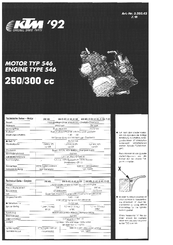
motor type 546
Brand: KTM
|
Category: Engine
|
Size: 10.69 MB
Table of Contents
-
Technical Data
1
-
Gear Ratios
2
-
Basic Carburetor Setting
2
-
Tolerances and Fitting Clearances
2
-
Gasket Thicknesses
2
-
Crank Case
3
-
Clutch Cover
4
-
Crankshaft, Piston
4
-
Cylinder
5
-
Twin Valve Control
5
-
Carburettor
6
-
Clutch
7
-
Kickstarter
7
-
Ignition System
8
-
Transmission
9
-
Shifting Mechanism
10
-
Cooling System
10
-
Special Tools
11
Advertisement
Related Products
-
KTM 250 EXC EU
-
KTM 250 EXC-F EU 2010
-
KTM 250 EXC EU 2010
-
KTM 250 EXC SIX DAYS EU 2010
-
KTM 250 EXC AUS 2010
-
KTM 250 EXC AUS
-
KTM 250 EXC Six days EU
-
KTM 250 EXC-F EU
-
KTM 250 EXC-F AUS
-
KTM 250 EXC-W USA
KTM Categories
Motorcycle
Motorcycle Accessories
Offroad Vehicle
Engine
Industrial Equipment
More KTM Manuals
Не можете найти ответ на свой вопрос в руководстве? Вы можете найти ответ на свой вопрос ниже, в разделе часто задаваемых вопросов о KTM 250 EXC (2012).
Как перевести мили в километры?
В чем разница между топливом E10 и E5?
Какова рекомендуемая частота замены масляного фильтра в двигателе KTM?
Как часто следует менять масло в двигателе KTM?
Как удалить ржавчину с устройства KTM мотоцикл?
Инструкция KTM 250 EXC (2012) доступно в русский?
Не нашли свой вопрос? Задайте свой вопрос здесь
owner’s Manuals
PowerWear & PowerParts Manuals
Here is your personal document
If you prefer a printed document to thumb through, or you would like to search for an older document, these are available in the Print on Demand portal.
In the portal, you can find owner’s and repair manuals for a wide variety of models.
You can choose between PDF downloads and printed copies.
To the Print on Demand portal
- Manuals
- Brands
- KTM Manuals
- Motorcycle
- 250 EXC
- Owner’s manual
-
Contents
-
Table of Contents
-
Troubleshooting
-
Bookmarks
Quick Links
BEDIENUNGSANLEITUNGEN
OWNER’S MANUAL
MANUALE O’USO
MANUEL D’UTILISATION
MANUAL DE INSTRUCCIONES
REPAIRMANUAL2005
REPARATURANLEITUNG
REPAIR MANUAL
MANUALE DI REPARAZIONE
MANUEL DE REPARATION
MANUAL DE REPARACION
FEDERBEIN
SHOCK ABSORBER
AMMORTIZZATORE
AMMORTISSEUR
AMORTIGUADOR
GABEL
FORK
FORCELLA
FOURCHE
HORQUILLA
Related Manuals for KTM 250 EXC RACING
-
-

-
-
Motorcycle KTM 125 EXC, EXC SIX DAYS, 200 XC, XC-W, EXC, 250 XC, XC-W, EXC, EXC SIX DAYS, 300 XC, XC-W, EXC-E, EXC-E SIX DAYS Owner’s Manual
Ktm owner’s manual motorcycle 125 exc, exc six days 200 xc, xc-w, exc 250 xc, xc-w, exc, exc six days 300 xc, xc-w, exc-e, exc-e six days (74 pages)
-
-
-
-


Summary of Contents for KTM 250 EXC RACING
-
Page 1
REPAIRMANUAL2005 BEDIENUNGSANLEITUNGEN REPARATURANLEITUNG FEDERBEIN GABEL OWNER’S MANUAL REPAIR MANUAL SHOCK ABSORBER FORK MANUALE O’USO MANUALE DI REPARAZIONE AMMORTIZZATORE FORCELLA MANUEL D’UTILISATION MANUEL DE REPARATION AMMORTISSEUR FOURCHE MANUAL DE INSTRUCCIONES MANUAL DE REPARACION AMORTIGUADOR HORQUILLA… -
Page 2
OWNER’S MANUAL 2005 250 EXC RACING 400 EXC RACING 450 SX, MXC, EXC RACING 525 SX, MXC, EXC RACING OWNER`S MANUAL MANUALE D`USO MANUEL D`UTILISATION MANUAL DE INSTRUCCIONES ART. NR. 3.211.39… -
Page 3
Take special care to follow the recommended run in, inspection, and maintenance intervals. Heeding these guidelines will significantly increase the life of your motorcycle. To ensure that all work to your KTM is performed properly and to avoid warranty conflicts, KTM recommends that you always have your KTM serviced by a recognized and qualified KTM dealer. -
Page 4: Important Limited Warranty And Limited Guarantee Information
» IMPORTANT LIMITED WARRANTY AND LIMITED GUARANTEE INFORMATION KTM sports motorcycles are designed and constructed to resist the usual wear and tear of normal use in competitions. The motorcycles comply with the regulations and categories currently in effect with the leading interna- tional motorcycle associations.
-
Page 5: Table Of Contents
Hand decompression lever …..6 General information about KTM disc brakes ..33 Hand brake lever ……6 Adjusting the free travel at the hand brake lever .
-
Page 6: Serial Number Locations
» SERIAL NUMBER LOCATIONS Chassis number The chassis number is stamped on the right side of the steering head tube. Enter this number in the field on page no 1. Engine number, engine type The engine number and the engine type are stamped into the left side of the engine below the engine sprocket.
-
Page 7: Operation Instruments
» OPERATION INSTRUMENTS Clutch lever The clutch lever [1] is located on the left side of the handlebar. The adjust- ing screw [A] is used to change the original position of the clutch lever (see maintenance work on chassis and engine). The clutch is hydraulically actuated and adjusts itself automatically.
-
Page 8: Flasher Switch
» OPERATION INSTRUMENTS Headlamp switch (EXC USA) In this model the headlamp is switched on with the pull switch [1]. Flasher switch The flasher switch is a separate unit and is mounted on the left portion of the handlebar. The wire harness is designed in a way that whenever you want to use your bike off-road, you can dismount the entire turn indicator system without affecting the function of the remaining electrical system.
-
Page 9: Electronic Speedometer
H displays the engine’s service hours. The service hour counter starts to count as soon as you start the engine. The displayed figure cannot be changed. Service intervals are indicated in service hours for some KTM offroad motor- cycles, making the service hour counter a very practical function.
-
Page 10
» OPERATION INSTRUMENTS Activating and deactivating display modes In the display mode SPEED/H, press and hold the button for 3 seconds to access the SETUP menu. The active functions will be displayed. The blink- ing function can be activated by pressing the + button and deactivated by pressing the –… -
Page 11
» OPERATION INSTRUMENTS LAP / LAP display mode (to view lap times) The LAP/LAP display mode will only be shown if lap times have been stored and the front wheel has stopped. It will display the lap number and the stopped lap time in hours, minutes and seconds. -
Page 12
» OPERATION INSTRUMENTS SPEED / A2 display mode (average speed 2) A2 shows the average speed based on the TR2 (tripmaster 2) and S2 (stop watch 2) figures. The displayed figure can deviate from the actual average speed if the TR2 figure was changed manually or if S2 was not stopped after the trip. -
Page 13: Setting The Clock
» OPERATION INSTRUMENTS Setting the clock To set the clock, switch the ignition off and select the SPEED/CLK mode. Press and hold the button for 3 seconds. The blinking digits can be changed using the + and — buttons. Press the button to move to the next digit.
-
Page 14: Filler Cap
» OPERATION INSTRUMENTS Filler cap To open the filler cap: Turn the filler cap counter-clockwise. To close the filler cap: Put the filler cap on and tighten it by turning it clockwise. Install the tank breather hose [1] without kinks. Fuel tap OFF In this position the fuel tap is closed.
-
Page 15: Shift Lever
» OPERATION INSTRUMENTS Shift lever The shift lever is mounted on the left side of the engine. The position of the gears is shown in the illustration. Neutral, or the idle speed, is located between first and second gear. 2,3,4 (5,6) Kickstarter The kickstarter is mounted on the right side of the engine.
-
Page 16: Compression Damping Of Fork
» OPERATION INSTRUMENTS Compression damping of fork Hydraulic compression damping determines the reaction when the fork is com- pressed. The degree of compression can be adjusted with adjusting screws at the bottom of the fork legs.Remove the protecting cap [1]. Turn the adjusting screws [2] clockwise to increase damping, turn it counter- clockwise to reduce damping during compression.
-
Page 17: Compression Damping Of Shock Absorber (Mxc, Exc)
» OPERATION INSTRUMENTS Compression damping of shock absorber (MXC, EXC) The compression damping (during compression) can be adjusted for the MXC and EXC shock absorbers (Mono Compression Control). The degree of damping can be adjusted by turning adjusting screw [1] with a screwdriver.
-
Page 18: General Tips And Warnings For Starting The Motorcycle
» GENERAL TIPS AND WARNINGS FOR STARTING THE MOTORCYCLE Instructions for initial operation – Verify that your KTM dealer performed the PREPARATION – WEAR SUITABLE CLOTHING WHEN DRIVING A MOTORCYCLE. OF VEHICLE jobs (see Customer Service Manual). CLEVER KTM DRIVERS ALWAYS WEAR A HELMET, BOOTS, GLOVES –…
-
Page 19: Driving Instructions
If the level of brake fluid falls below the minimum value, this indicates a leak in the braking system or completely worn out brake pads. Arrange for the braking system to be checked by a KTM specialist, as com- plete failure of the braking system can be avoided.
-
Page 20: Starting When The Engine Is Cold
» DRIVING INSTRUCTIONS Starting when the engine is cold 1 Open the fuel tap [1]. 2 Swing up the side stand or center stand. 3 Put the gear in neutral. 4 Operate the choke [2]. 5 Leave throttle closed and kick the kickstarter briskly ALL THE WAY or actu- ate the E-starter.
-
Page 21: Braking
TION THAT SOMETHING IS WRONG WITH THE BRAKE SYSTEM. DON’T 35 mm RIDE YOUR MOTORCYCLE ANYMORE WITHOUT FIRST HAVING THE BRAKE SYSTEM LOOKED OVER BY A KTM DEALER. Stopping and parking Apply the brakes fully and put the engine into neutral. To turn off the engine, push the short-circuit button or the emergency-OFF button with the engine at idling speed until the engine stops.
-
Page 22: Periodic Maintenance
IF MOTORCYCLE IS USED FOR COMPETITION 15 HOURS SERVICE SHOULD BE CARRIED OUT AFTER EVERY RACE. Service intervalls should never be exceeded by more than 2 hours or 15 liters of fuel. Maintenance work done by KTM authorised workshops is not a substitute for care and checks done by the rider.
-
Page 23
» PERIODIC MAINTENANCE IMPORTANT CHECKS AND MAINTENANCE TO BE CARRIED OUT BY THE RIDER Before each After every For cross- start cleaning country use Check oil level Check brake fluid level Check brake pads for wear Check lights for function Check horn for function Lubricate and adjust cables and nipples Bleed fork legs regularly… -
Page 24
» PERIODIC MAINTENANCE RECOMMENDED INSPECTION OF THE 250/400/450/525 SX AND EXC ENGINE USED FOR ENDURO COMPETITIONS BY YOUR KTM WORKSHOP (ADDITIONAL ORDER FOR THE KTM WORKSHOP) hours hours hours hours hours hours hours a 100 liter fuel consumption is equivalent to approx. 15 operating hours… -
Page 25
» PERIODIC MAINTENANCE RECOMMENDED INSPECTION OF THE 250/400/450/525 EXC ENGINE USED FOR HOBBY — ENDURO COMPETITIONS BY YOUR KTM WORKSHOP (ADDITIONAL ORDER FOR THE KTM WORKSHOP) hours hours hours hours hours hours hours a 100 liter fuel consumption is equivalent to approx. 15 operating hours… -
Page 26: Maintenance Work On Chassis And Engine
CARBURETOR OR FUEL TANK – ONLY USE SPECIAL SCREWS WITH AN APPROPRIATE THREAD LENGTH SUPPLIED BY KTM TO FIX THE SPOILERS ON THE TANK. USING OTHER SCREWS OR LONGER SCREWS CAN CAUSE LEAKS IN THE TANK THROUGH WHICH FUEL CAN FLOW OUT.
-
Page 27: Basic Suspension Setup For The Weight Of The Driver
To achieve maximum handling performance and to prevent the fork, shock absorber, swing arm and frame from being damaged, the basic setup of the suspension components must be suitable for your weight. At delivery, KTM’s offroad motorcycles are set to accommodate a driver weighing 70 — 80 kg (wear- ing full protective clothing).
-
Page 28: Checking The Basic Setup Of The Telescopic Fork
The type number of the telescopic fork is embossed on the caps on the top of the telescopic fork. If you are uncertain which spring to use, contact your KTM workshop. 4,4 N/mm…
-
Page 29: Breather Plug Front Fork
» MAINTENANCE WORK ON CHASSIS AND ENGINE Breather plug front fork After every 5 hours of use for competitive racing, slacken the breather plugs [1] a few turns in order to relieve excess pressure from the inside of the fork. To do this, place the motorcycle on a stand with the front wheel lifted off the ground.
-
Page 30: Changing The Fork Offset (Caster) (Sx)
» MAINTENANCE WORK ON CHASSIS AND ENGINE Changing the fork offset (caster) (SX) * The fork offset [A] in the SX models (center fork legs — center steering head angle) can be set to either 18 or 20 mm. This allows you to optimize the han- dling to match the race course.
-
Page 31: Checking And Adjusting The Steering Head Bearing
» MAINTENANCE WORK ON CHASSIS AND ENGINE Mount the lower triple clamp, upper steering head bearing, protection ring, O-ring, upper triple clamp and the blind screw. Tighten the collar screw on the lower triple clamp to 80 Nm. Mount the fork legs and tighten the clamp screws on the lower triple clamp to 10 Nm in 3 stages.
-
Page 32: Check Chain Tension
Tighten collar nut [1] to 80 Nm. – IF YOU DON’T HAPPEN TO HAVE A TORQUE WRENCH AT HAND, MAKE SURE YOU HAVE THE TIGHTENING TORQUE CORRECTED BY A KTM DEALER AS SOON AS POSSIBLE. A LOOSE AXLE MAY LEAD TO AN UNSTABLE DRIVING BEHAV- IOR OF YOUR MOTORCYCLE.
-
Page 33: Chain Maintenance
» MAINTENANCE WORK ON CHASSIS AND ENGINE Chain maintenance For a long chain life, good maintenance is very important. Chains without X-rings should be cleaned in fireproof solvent regularly and afterwards treated with hot grease or chain spray (e.g. Motorex Chainlube 622). X-ring chains on the other hand are very simple to clean.
-
Page 34: General Information About Ktm Disc Brakes
CONSTITUTE A SAFETY RISK. HAVE THE BRAKE DISCS REPLACED IMMEDI- ATELY AS SOON AS THEY REACH THE WEAR LIMIT. – HAVE ANY REPAIRS ON THE BRAKE SYSTEM BE PERFORMED BY A KTM DEALER BRAKE FLUID RESERVOIRS: The brake fluid reservoirs on the front and rear wheel brakes have been designed in such a way that even if the brake pads are worn it is not neces- sary to top up the brake fluid.
-
Page 35: Adjusting The Free Travel At The Hand Brake Lever
IF THE BRAKE FLUID LEVEL DROPS BELOW THE MINIMUM EITHER THE BRAKE SYSTEM HAS A LEAK OR THE BRAKE PADS ARE COMPLETELY WORN. IN THIS CASE, CONSULT AN AUTHORIZED KTM DEALER IMMEDIATELY. Refilling the front brake fluid reservoir * Loosen screws [2] and remove lid [3] and membrane [4].
-
Page 36: Replacing The Front Brake Pads
IF THE BRAKE FLUID LEVEL DROPS BELOW THE MINIMUM EITHER THE BRAKE SYSTEM HAS A LEAK OR THE BRAKE PADS ARE COMPLETELY WORN. IN THIS CASE, CONSULT AN AUTHORIZED KTM DEALER IMMEDIATELY. Refilling the rear brake fluid reservoir * Add brake fluid as soon as a bubble is visible in inspection glass [A].
-
Page 37: Checking The Rear Brake Pads
» MAINTENANCE WORK ON CHASSIS AND ENGINE Checking the rear brake pads min. The brake pads can be inspected from the rear. The thickness of the linings may not be less than 1 mm (0.04 in). 1 mm AT THEIR MOST WORN POINT BRAKE PAD LININGS SHOULD NOT BE THINNER THAN 1 MM, OTHERWISE THEY COULD LEAD TO BRAKE FAILURE.
-
Page 38: Dismounting And Mounting The Rear Wheel
MAINTENANCE WORK ON CHASSIS AND ENGINE – IF YOU DON’T HAPPEN TO HAVE A TORQUE WRENCH AT HAND, MAKE SURE YOU HAVE THE TIGHTENING TORQUE CORRECTED BY A KTM DEALER AS SOON AS POSSIBLE. A LOOSE AXLE MAY LEAD TO AN UNSTABLE DRIVING BEHAV- IOR OF YOUR MOTORCYCLE.
-
Page 39: Tires, Air Pressure
– Tire pressure should be checked regularly on a “cold” tire. Proper pres- sure ensures optimum driving comfort and extends the life of your tires. TIRES-AIR PRESSURE – DO NOT MOUNT TIRES WHICH HAVE NOT BEEN APPROVED BY KTM. OTHER front rear TIRES COULD HAVE ADVERSE EFFECTS ON THE WAY YOUR MOTORCYCLE BEHAVES.
-
Page 40: Battery (Mxc/Exc)
» MAINTENANCE WORK ON CHASSIS AND ENGINE Battery (MXC/EXC) The battery is located under the seat and is maintenance-free. It is not necessary to check the electrolyte level or to refill water. Simply keep the battery poles clean and slightly grease them with an acid-free grease if necessary.
-
Page 41: Fuse (Mxc/Exc)
Replace a blown fuse only with an equivalent one. If a new fuse that has just been installed gets blown again, you are strongly advised to have it inspected by a KTM dealer. The fuse capacity is 10 Ampere. UNDER NO CIRCUMSTANCES IS A STRONGER FUSE ALLOWED TO BE INSTALLED OR A FUSE ALLOWED TO BE “REPAIRED”.
-
Page 42: Cooling System
– EXTREME CLIMATE CONDITIONS OR STOP AND GO TRAFFIC MAY CAUSE OVER- HEATING PROBLEMS. TO AVOID THIS, AN ELECTRIC BLOWER [4] IS OFFERED FOR MODELS WITH ELECTRIC STARTERS (ASK YOUR KTM DEALER) Checking the coolant level The coolant should be 10 mm (0.4 in) above the radiator fins when the engine is cold (see diagram).
-
Page 43: Replacing The Glassfiber Yarn Packing Of The Silencer
Then, drill open the rivets and remove the end cap. NOTE! In every exhaust repair procedure, the O-rings must be replaced by new ones. Glass fiber yarn packings are available from your licensed KTM mechanic. THE EXHAUST SYSTEM BECOMES VERY HOT WHILE THE MOTORCYCLE IS RUN- NING.
-
Page 44: Cleaning The Air Filter
The SX models do not have a throttle cap. – DO NOT CLEAN FOAM FILTER WITH FUEL OR PETROLEUM SINCE THESE DAM- AGE THE FOAM. KTM RECOMMENDS THE PRODUCTS OF THE COMPANY MOTOREX FOR AIR FILTER MAINTENANCE (BIO DIRT REMOVER AND LIQUID BIO POWER).
-
Page 45: Changing The Original Position Of The Clutch Lever
If necessary, fill up with biodegradable hydraulic oil SAE 10 (e.g. Motorex Kupplungs-Fluid 75).Biodegradable hydraulic oil is available from your KTM dealer (50ml). KTM USES BIODEGRADABLE HYDRAULIC OIL FOR THE HYDRAULIC CLUTCH CON- TROL. NEVER MIX BIODEGRADABLE HYDRAULIC OILS WITH MINERAL OILS. NEVER REFILL WITH MINERAL HYDRAULIC OIL OR BRAKE FLUID.
-
Page 46: Carburetor — Adjust Idling (Keihin-Fcrmx 37/39/41)
» MAINTENANCE WORK ON CHASSIS AND ENGINE CARBURETOR – Adjust idling (Keihin-FCRMX 37/39/41) * Idling adjustment of the carburetor strongly affects the engine’s starting behavior. That is, an engine whose idling speed is adjusted correctly will be easier to start than one whose idling speed has not been adjusted correctly. The idle speed is controlled by means of the adjusting wheel [1] and the mixture control screw [2].
-
Page 47: Draining The Float Chamber Of The Carburetor
» MAINTENANCE WORK ON CHASSIS AND ENGINE Draining the float chamber of the carburetor Following every wet cleaning procedure, the float chamber of the carburetor should be drained in order to remove any water that may have penetrated into it. Water in the float chamber causes malfunctioning. Perform this task on a cold engine.
-
Page 48: Engine Oil
32°F Only use fully synthetic engine oils that meet the JASO MA quality require- ments (see information on the can). KTM recommends Motorex Power Synt 4T in the 10W/50 viscosity (for tem- 5W/40 10W/50 peratures over 0°C, 32°F) or 5W/40 (for temperatures under 0°C, 32°F).
-
Page 49: Changing Oil Filters
» MAINTENANCE WORK ON CHASSIS AND ENGINE Changing the oil filters Remove the screw [1] and swing the brake fluid container sideward. Place a receptacle underneath the engine to collect the drained oil. Remove the 4 screws [2] and dismount the two oil filter covers. Using circlip pliers, pull the oil-filter inserts [3] out of the housing.
-
Page 50: Troubleshooting
We would like to point out that many operations cannot be performed by yourself. In case of uncertainty, please contact a KTM-dealer. TROUBLE…
-
Page 51
Dismount left side paneling and filter box cover, replace E-starter do not work fuse The battery is discharged The battery isn’t charged by the generator Remove seat and fuel tank and check voltage regulator con- because nections; voltage regulator and generator should be checked by a KTM dealer. -
Page 52: Storage
» CLEANING Clean your motorcycle regularly in order to maintain the beauty of its plastic surfaces. The best manner would be to use warm water that has been mixed with a normal brand-name washing detergent and a sponge. The hard dirt can be removed before washing with the help of a soft water jet. NEVER CLEAN YOUR MOTORCYCLE WITH A HIGH-PRESSURED CLEANER OR A HIGH-PRESSURED WATER JET.
-
Page 53: Technical Data — Engine
» TECHNICAL DATA — ENGINE TYPE 250 EXC 400 EXC 450 SX 450 MXC 450 EXC 525 SX 525 MXC-G 525 EXC 525 MXC DESERT Design Liquid-cooled single cylinder 4-stroke engine with balancer shaft Displacement 250 cm 398 cm 449 cm 448 cm 510 cm Bore/Stroke…
-
Page 54
» TECHNICAL DATA — ENGINE BASIC CARBURATOR SETTING 250 EXC RACING 400 EXC RACING 400 EXC-G RACING USA 450 EXC RACING EU / AUS EU / AUS EU / AUS 11 kW 12 kW 12 kW Type Keihin FCR-MX 3700A Keihin FCR-MX 3900C Keihin FCR-MX 3900C Keihin FCR-MX 3900A… -
Page 55
Only use fully synthetic engine oils that meet the JASO MA quality require- JASO T903 MA ments (see information on the can). KTM recommends Motorex Power Synt 4T in the 10W/50 viscosity (for tem- peratures over 0°C, 32°F) or 5W/40 (for temperatures under 0°C, 32°F). TEMPERATUR 0°C… -
Page 56: Technical Data — Chassis
» TECHNICAL DATA — CHASSIS CHASSIS 450/525 SX 250/400/450/525 EXC/MXC DESERT 450/525 MXC-G, EXC-G USA Frame Central tube chrome-moly-steel frame Fork 4860 PA/MA WP Up Side Down 4860 MA Wheel travel front/rear 300/335 mm Rear suspension WP Progressive Damping System shock absorber, aluminium swing arm Front brake Disk brake with carbon-steel brake disc Ø…
-
Page 57
» TECHNICAL DATA — CHASSIS TIGHTENING TORQUES — CHASSIS Collar screw, front wheel spindle M24x1,5 40 Nm Brake caliper, front Loctite 243 + 25 Nm Brake caliper, FTE radial front M10x1,25 Loctite 243 + 40 Nm Brake disk Loctite 243 + 10 Nm Clamping screws, upper fork bridge EXC 20 Nm Clamping screws, lower fork bridge EXC… -
Page 58
Changing the basic position of the foot brake pedal . .35 General information about KTM disc brakes ..33 Changing the engine oil ….. .47 General tips and warnings for starting the motorcycle .17… -
Page 61
ANHANG – APPENDICE APPENDIX – APÉNDICE… -
Page 63
» SCHALTPLAN WIRING DIAGRAMM ENGLISH DEUTSCH ITALIANO Battery Batterie Batteria Cooling fan Lüftermotor Motorino ventola Driving light lamp Fernlichtkontrolle spia abbagliante Flasher control lamp Blinkerkontrolle spia lampeggiatori Flasher relay Blinkerrelais Relè indicatori Front brake switch vorderer Bremslichtschalter Interruttore luce ant. di stop Generator Generator Generatore… -
Page 64
» SCHALTPLAN WIRING DIAGRAMM ENGLISH FRANCAIS ESPANIOL Battery Batterie Batería Cooling fan Ventilateur Motor del ventilador Driving light lamp temoin feu route lampara aviso luces largas Flasher relay Relais de clignotants Relé de la luz intermitente Flasher control lamp temoin de clignoteur lampara aviso intermitentes Front brake switch Contacteur de frein avant… -
Page 65
REPAIRMANUAL2000-2005 250 EXC RACING 400/450 SX,MXC,EXC,SMR,SXS RACING 520/525 SX,MXC,EXC,SMR RACING 540 SXS RACING, 610 CRATE REPARATURANLEITUNG MANUALE DI RIPARAZIONE MANUEL DE RÉPARATION MANUAL DE REPARACIÓN… -
Page 66
1 SERVICE-INFORMATIONS 2 GENERAL INFORMATION 3 REMOVING AND REFITTING ENGINE 4 DISASSEMBLING ENGINE 5 SERVICING INDIVIDUAL COMPONENTS 6 ASSEMBLING ENGINE 7 ELECTRICAL 8 FUEL SYSTEM 9 TROUBLE SHOOTING 10 TECHNICAL SPECIFICATIONS 11 PERIODIC MAINTENANCE SCHEDULE 12 WIRING DIAGRAMS… -
Page 67
X P L A N A T I O N P D A T I N G 3.205.85-E Repair Manual 400/520 SX, MXC, EXC RACING Basic version Model year 2000 (Engine number with first digit “0“) 2/2000 3.210.01-E Updating of Rep.Manual 3.205.85-E Model year 2001 (Engine number with first digit “1“) 1/2001… -
Page 68
„NOTE” POINTS OUT USEFUL TIPS. Use only ORIGINAL KTM SPARE PARTS when replacing parts. The KTM high performance engine is only able to meet user expectations if the maintenance work is performed regularly and professionally. In accordance with the international quality management ISO 9001 standard, KTM uses quality assurance processes that lead to the highest possible product quality. -
Page 69
2stroke / 4stroke Racing / 625 SXC / 660 SMC Countries: Dear KTM Distributor! Due to a defect on the injection tool for filler cap 590 07 009 000 at our supplier, it may happen, that the bleeding holes keep closed. -
Page 70
450 EXC Racing 2004 as per Excel file Countries: AU, ES, IT, UK, US Dear KTM Distributer! On all 450 EXC bikes listed in the attached Excel sheet cracks on the drive gear for the balancer shaft can occur due to hardening failures. -
Page 71
594 30 035 000 (0.8 mm). This new gasket may be ordered individually and is available immediatley in the KTM Spare Parts Center. It is also included in the gasket set in a separate package marked for models 450 EXC and 450 MXC. -
Page 72
Excel file. Please order the required quantities from the KTM Spare Parts Center. For this retrofit KTM will compensate the parts and through the use of Code T39002 36 970 10 minutes of labour per motorcycle. T.Stöcklmeier W. -
Page 73
The additional tank „left ´99“, wich is connected to the left radiator via a hose, is used as a expansion reservior and should be filled half with coolant. Take care to mount the hose without any kink. Bild KTM-Nummer Description 590.35.007.000 RADIATOR L/S(45328)RAC.2000 580.35.016.000… -
Page 74
400 / 520 SX / EXC RACING Model: Countries: The KTM-RACING 4-stroke is designed and developed as a non compromise pro level competiti- on racing motorcycle. In order to keep the bike ready for operation and to keep it reliable, proper maintainance is absolutely essential. -
Page 75
„pitting“. Replacement necessary when impressions exceed the 2/3 of tooth width. Further on transmission gears the shifting dogs have to be checked in terms of wear. • Grind-in valves during large maintainance. For price information please call KTM spareparts department. T. Stöcklmeier E. Sellmaier… -
Page 76
Customer Service Subject: carburetor retrofit action Model: 250 EXC Racing 4stroke 2002 model series Countries: To improve throttle response at low RPM’s, the following carburetor retrofit-procedure, including changes of setting is recommended. a) Replace diaphragm for accelerator pump with the new part no. 590 31 057 000 b) If the carburetor is still equipped with coil spring 590 31 059 000 (silver coated), that spring has to be replaced by coil spring part no. -
Page 77
Abt.: KD Nr.: 0001/31/01-E 12.01.2000 Regarding: Deristriction Modell: 400 / 520 EXC Racing modellyear 2000 Countries: Perform the following rebuilding work : 1) remove restrictor from silencer 2) remove filtercap from the airbox 3) remove slide limit stop on right side, under the plastic cover of carburetor 4) remove jet needle OBDVR and install OBDTM;… -
Page 78
Dpt.: No.: 0203/36/01-E 18.03.2002 Customer Service Subject: Engine smoking Model: 540 SXS Countries: When engine smoking is detected, the reason may be damaged valve shaft seals, as a consequence of valve sleeves, not been pressed onto final seat position. Due to this, the overlapping valve collets (see fig.A) touch and damage the valve shaft seals. To solve that problem, both valve collets have to be shortened 1,0 mm by grinding them carefully at the lower edge ( see fig.B). -
Page 79
Dpt.: Nr.: 0111/36/02-E 30.11.2001 Customer Service subjekt: automatic decompression stop-screw model: all 2001 4stroke Racing models countries: CORRECTION: Part number of ah-screw must read 0912 050106 To prevent engine damages, caused by a loosen stop-screw at auto decompression device, we recommend for engines in 2001 models during repairs or maintainance work (according to owners manuals) to replace ah-screw 0912 050106 (fig.A) by a new one and to replace… -
Page 80
To guarantee sufficient space between the components, KTM offers following parts, which can be ordered as a “set”, but also as single parts, at KTM Spareparts Center. Spacer set Nr. -
Page 81
Dept.: KD Nr.: 0003/31/02-E 14.03.00 Regarding: Hotstart behaviour Model: 400 / 520 SX RACING Countries: To improve the behaviour of a hotstart, we suggest to use a 48 idlejet and a setting of the mixture screw of: “one rotation open”. The carburettor needle should be set to position IV (from top) on the 400 SX and to position III (from top) on the 520 SX. -
Page 82
Please note at some modells (125 SX, 200 SX, 525 SX Racing 2003), that the brake piston diameter is either 26 mm or 28 mm. Before ordering please make sure which diameter your brake system has. KTM-Numbers: Brake system rear 26 mm: 503.13.080.244 BRAKE CALIPER REAR CPL. -
Page 83
To eliminate the possibility of over-revving and to maintain the present performance, the 2003 525SX models must be retrofitted with KTM CDI-box 590 39 031 100 in combination with the cable adapter 590 39 033 000. Therefore the equivalent quantity of these parts, appropriate to the number of bikes delivered to your market, have been prepared for you at KTM spareparts center. -
Page 84
Dpt.: No.: 0301/32/01-E 27.01.2003 Customer Service Subject: Clutch plates kit Model: 450 SX and 525 SX / 2003 Countries: To improve the damping function of the clutch and subsequently careful treatment of the gearbox against pittings formation, during service, maintainance or repairs, we recommend to equip the clutch discs kit with: 6 pcs. -
Page 85
In case of consequential damage all further needed parts have to be returned and the labour has to be adapted according to the flat rate manual. Claims can only be approved when the complete cylinder head was received at KTM Austria. T.Stöcklmeier E.Sellmaier… -
Page 86
2-1E GENERAL INFORMATION INDEX OIL CIRCUIT ……….2-2 ENGINE OIL . -
Page 87
2-2E Oil circuit Via the long oil screen , the oil pump draws engine oil from the oil sump of the transmission. This engine oil flows through an oil line into the cylinder head for camshaft lubrication ; the oil quantity is controlled by the jet bolt . -
Page 88
Only use fully synthetic engine oils that meet the JASO MA quality requirements (see information on the can). 5W/40 10W/50 KTM recommends Motorex Power Synt 4T in the 10W/50 viscosity (for temperatures over 0°C, 32°F) or 5W/40 (for temperatures under 0°C, 32°F). Checking the engine oil level The engine oil level can be checked with the engine being either warm or cold. -
Page 89
2-4E Changing the engine oil NOTE: When changing the engine oil, it is necessary to clean the short and long oil screens and to replace both oil filters. Engine oil has be changed with the engine being at an operating temperature. -
Page 90
2-5E Changing the oil filters – Remove the bolt and swing the brake fluid container sideward. Place a receptacle underneath the engine to collect the drained oil. Remove the 4 bolts and dismount the two oil filter covers. – Using circlip pliers, you may now pull the oil-filter inserts out of the housing. -
Page 91
2-6E Checking the oil level of the hydraulic clutch To check the oil level in the master cylinder of the clutch remove the cover. For this purpose, remove bolts and cover together with the rubber boot . The oil level in the horizontal-standing master cylinder should be 4 mm (0,157 in) below the upper edge. -
Page 92
2-7E… -
Page 93
2-8E SPECIAL TOOLS – ENGINE PART NO. DESCRIPTION 560.12.001.000 Universal engine work stand 590.29.002.000 Engine holder for engine work stand 590.29.020.000 Rivetting tool for steering chain 590.29.005.010 Mounting sleeve for shaft seal ring water pump 510.12.011.000 Circlip pliers 590.29.021.044 Puller for driving hub and primary gear 598.29.015.075 Piston ring spanner Ø… -
Page 94
2-9E CLEANING Clean your motorcycle regularly in order to maintain the beauty of its plastic surfaces. The best manner would be to use warm water that has been mixed with a normal brand-name washing detergent and a sponge. The hard dirt can be removed before washing with the help of a soft water jet. CAUTION EVER CLEAN YOUR MOTORCYCLE WITH A HIGH PRESSURED CLEANER OR A HIGH… -
Page 95
3-1E DISMOUNTING AND MOUNTING THE ENGINE INDEX DISMOUNTING THE ENGINE ……..3-2 MOUNTING THE ENGINE . -
Page 96
3-2E Dismounting the engine – Clean the motorcycle thoroughly and prop it up on a stable stand. – Dismount the seat and the tank with spoilers. – Disconnect the ground cable of the battery. – Remove the screw and detach the 2 tension springs –… -
Page 97
3-3E – Remove the carburetor cover and unhitch both throttle cables. – Detach the return spring of the footbrake pedal. – Remove the 2 screws and take off the frame cover. – Open the radiator cap. – Remove the screw at the cylinder together with the sealing ring and drain the coolant into a receptacle. -
Page 98
3-4E – Remove the bolts and take off the sprocket cover. – Remove the 2 bolts of the clutch slave cylinder and pull the clutch slave cylinder off the casing. – Swing the chain damper plate backwards. – Open the chain joint and remove the chain from the vehicle. –… -
Page 99
3-5E Mounting the engine – Lift the engine into the frame and move into the correct position. – Slightly grease the swing arm bolt and mount the hexagon nut but do not tighten yet. – Slightly grease both engine fixing screws and mount to 60 Nm. -
Page 100
3-6E – Insert the rear end of the carburetor in the carburetor connection boot and the front end in the intake flange. – Mount and tighten both hose clamps. – Attach both throttle cables and mount the carburetor cover. – Connect the plug connector on the throttle sensor. –… -
Page 101
3-7E – Mount the exhaust system. – Connect the ground wire to the battery. – Mount the seat and tank together with the spoilers. Bleeding the cooling system To bleed the cooling system, fill in approx. 0.8 liters (0.2 US gallons) of coolant and remove the bleeder bolt . -
Page 102
4-1E DISMANTLING THE ENGINE INDEX DRAINING THE ENGINE OIL ……..4-2 DISMOUNTING THE OIL FILTER . -
Page 103
4-2E Draining the engine oil – Remove the bolts , and , and drain the engine oil into a receptacle. – Remove kickstart and shift lever. Dismounting the oil filter – Unfasten the 4 bolts and remove both oil filter covers –… -
Page 104
4-3E Disassembling the clutch – Loosen all bolts of the clutch cover and dismount clutch cover together with gasket. – Pull the 2 dowels out of the engine casing. – Loosen the bolts in a crosswise order to prevent the clutch discs from getting jammed when the clutch springs are released. -
Page 105
4-4E – Turn crankshaft to TDC. NOTE: In the TDC position, the guidepiece will be above the pulser coil (see photo). – Turn out the crankshaft fixing bolts and remove the sealing ring – Turn in the crankshaft fixing bolt by hand. –… -
Page 106
4-5E – Apply the special tool 590.29.003.100 as shown, loosen the collar nut from the primary gear and remove. – Remove the special tool. CAUTION OLLAR NUTS WITH LEFT HAND THREAD AND WITH RIGHT HAND THREAD WERE «LEFT» USED RESPECTIVELY OLLAR NUTS LABELED AS HAVE A LEFT HAND… -
Page 107
4-6E From the 2003 model: – Remove the outer clutch hub together with the stepped disk and both half disks from the main shaft. – Remove both needle bearings and the supporting plate. Dismounting the oil pump – Loosen the 2 bolts and remove the oil pump cover. -
Page 108
4-7E Dismounting the upper cylinder-head portion – Loosen each of the 6 bolts together with their sealing rings and dismount both valve covers together with their gaskets. – Unscrew the spark plug. – Unfasten 4 bolts and dismount the water pump cover together with its gasket. -
Page 109
4-8E – Apply the timing chain separating tool 590.29.020.000 and open the timing chain by turning the spindle (see photo). CAUTION – M AKE SURE THAT THE PUSHED OUT BOLTS DO NOT FALL INTO THE ENGINE – P REVENT THE TIMING CHAIN FROM FALLING INTO THE CHAIN TUNNEL –… -
Page 110
4-9E – Remove the wire circlip and the push piston bolt from the piston. Dismount the piston. Dismounting timing chain and timing gear – Loosen the 2 bolts and dismount the fall-out protection element – Remove the timing chain. – Remove the bolts . -
Page 111
4-10E Dismounting E-starter drive gear and kickstarter – Remove the 2 circlips and the stop discs. Pull the kickstarter idler gear and the E-starter idler gear off the bearing bolts. – Pull the reduction gear and the needle bearing off the bearing bolt. Take the bearing bolt out of the engine casing. -
Page 112
4-11E Dismounting primary gear and free wheel – Remove the collar nut CAUTION OLLAR NUTS WITH LEFT HAND THREAD AND WITH RIGHT HAND THREAD WERE «LEFT» USED RESPECTIVELY OLLAR NUTS LABELED AS HAVE A LEFT HAND THREAD OLLAR NUTS WITHOUT LABELING HAVE A RIGHT HAND THREAD NOTE: The collar nut was already removed from the 250 EXC… -
Page 113
4-12E Dismounting shift mechanism and transmission – Turn the engine sideward. – Unfasten the engine fixture at the engine work stand – Applying a suitable tool to the cast-on members on the casing, lift off the left half of the casing, or separate it from the right half by slightly tapping on the countershaft with a plastic hammer. -
Page 114
4-13E Dismounting balancer shaft and crankshaft – Turn the crankshaft until the marks on the balancer shaft and crankshaft match. – In this position, the balancer shaft can be pulled out of the bearing seat. – Pull the crankshaft out of the bearing seat. –… -
Page 115
5-1E SERVICING INDIVIDUAL COMPONENTS INDEX LEFT CASING HALF ……….5-2 RIGHT CASING HALF . -
Page 116
IMPORTANT NOTE REGARDS WORKING ON ENGINE HOUSING Read through the following section before commencing work. Then determine the assembly sequence so that the engine housing halves only need to be heated up once before replacing the bearings. Having first removed the dowels, in order to expel the bearings or remove them with light mallet blows, the housing halves must be placed on a suitably large plane surface, supporting the whole of the sealing surface without damaging it. -
Page 117
5-2E Left casing half Remove all shaft seal rings and use an oven to heat the casing half to approx. 150°C. Cylindrical roller bearing of crankshaft Use a suitable punch to press the cylindrical roller bearing from the outside to the inside. From the inside, press in a new cylindrical roller bearing up to the stop. -
Page 118
5-3E The oil pump housing must not have any score marks or seizing marks. Blow compressed air through all oil ducts and check them for unobstructed passage. Check the 2 dowels for tight fit and, if necessary, adhere them by means of Loctite 243. -
Page 119
5-4E Grooved ball bearing and seal ring of balancer shaft. Use a bearing extractor to pull the grooved ball bearing out of the casing half and remove the seal ring. Press a new shaft seal ring in to a flush position, its open side facing downward. -
Page 120
5-5E Oil jet «100» Dismount the oil jet and clean with compressed air. Degrease the thread of the oil jet, apply Loctite 243 and mount the oil jet. NOTE: This jet is used to dose the amount of oil for the conrod bearing. Bypass valve Check valve plunger, sealing seat, and pressure spring for damage. -
Page 121
5-6E Crankshaft If the conrod bearing is replaced, take care to properly position the crankpin. The bores of the crank web and crank pin must coincide. CAUTION F THE CRANK PIN IS PRESSED IN THE WRONG POSITION THE CONROD BEARING IS SUPPLIED INSUFFICIENTLY OR NOT AT ALL WITH ENGINE OIL WHICH RESULTS IN BEARING DAMAGE… -
Page 122
5-7E Crankshaft webs – measure outer dimension Crankshaft webs – measure outer dimension with a sliding caliper as illustrated. Crankshaft webs – outer dimension = 65 mm ± 0.05 mm Driving gear of balancer shaft – Before pulling the driving gear off the balancer shaft you have to remove the inner ring of the crankshaft bearing: –… -
Page 123
5-8E Cylinder – Nikasil coating Nikasil is the brand name for a cylinder coating process, developed by the piston manufacturer Mahle. The name is derived from the two materials used in this process — a nickel layer into which the particularly hard silicon carbide is embedded. -
Page 124
5-9E Checking the piston – Replace the piston in the case of excessive oil consumption or grooves in the piston skirt. – If reinstalling the old piston perform the following steps: 1. Piston bearing surface — check for damage. 2. Piston ring grooves — the piston rings must move easily in the groove. Old piston rings or sandpaper (400 grit) may be used to clean the piston ring grooves. -
Page 125
5-10E Lubrication system Oil line Check for hairline cracking at the soldering joints, blow compressed air through the oil line and, while doing that, check it for unobstructed passage. In addition, check the oil line for possible scuff marks and replace the copper seal rings (8x12x1) O-rings Replace the O-rings during every oil filter change. -
Page 126
5-11E Upper portion of cylinder head – Remove circlip and pull the decompressor shaft together with spring out of the bore. – Pull the two end pieces together with the rocker arm pins out of the cylinder head’s upper portion. Withdraw the rocker arms –… -
Page 127: Cylinder Head
5-12E Cylinder head – Loosen the 3 bolts and dismount the exhaust flange together with its gasket. – Dismount the 4 valves with the aid of a special tool 590.29.019.000. NOTE: When being mounted again, used valves must be mounted in the same valve guide as before.
-
Page 128
5-13E – Take the valve spring retainer and the valve springs out of the cylinder head. – Pull the valve stem gaskets off the valve guides and remove the spring seats Sealing surface Check the spark plug thread and the valve seats for damage and cracks. Use a ruler and a feeler gauge to check the sealing surface of the cylinder head for distortion. -
Page 129
5-14E Camshaft – Dismount circlip and water pump wheel – Pull the needle roller out of the hole in the camshaft and pull the gasket carrier off of the camshaft. – Use the puller tool 590.29.033.000 to extract the grooved ball bearing from the camshaft (see photo). -
Page 130
5-15E – Press the shaft seal rings out of the gasket carrier – Press the new shaft seal rings in up to a flush position, with the open side facing outwards. Thoroughly grease the sealing lips. – Take the 2 O-rings off the gasket carrier and remove the gasket residues with a wire brush. -
Page 131
5-16E Timing chain tensioner – Pull the pressure pin of the timing chain tensioner out all the way and check whether or not it moves smoothly. – Check the toothing on the pressure pin and the ratcheting pawl for wear. –… -
Page 132
5-17E Modification — Model 2001 Modification — Model 2002 Checking the clutch for wear Modification — Model 2002 Thrust bearing Check it for seizing marks and unobstructed movability. Push rod Place it on a planar surface and check it for eccentricity. Clutch springs Minimum length: 42 mm, new: 43 mm;… -
Page 133
5-18E From the 2003 model LOCTITE 243 LOCTITE 243 Checking the clutch for wear Pressure piece Check it for seizing marks and unobstructed movability. Axial needle bearing Check for damage. Push rod Place it on a planar surface and check it for eccentricity. Clutch springs Minimum length: 42 mm, new: 43 mm;… -
Page 134
5-19E Checking the kickstarter for wear Take all components off the kickstarter shaft and clean them. Kickstarter gear Check the toothing for wear and the bearing for clearance. Kickstarter idler gear Check the bearing for clearance and seizing marks. Check the toothing for wear. -
Page 135
5-20E… -
Page 136
5-21E Shift mechanism Shift forks Check plate for wear. The forks are 4.8mm — 4.9 mm thick in a new condition. The wear limit is at 4.6 mm. Shift roller Check the shift grooves for wear. Check the fit of the shift roller in the grooved ball bearing Grooved ball bearing Check it for smooth movability. -
Page 137
5-22E Transmission Clamp the main shaft or counter shaft, respectively, into the vise (use protective jaws). Remove the gears and check the following parts for wear and grooves: – Bearings – Pivot points of the main shaft and countershaft and pivot points of the idler gears –… -
Page 138
5-23E Transmission Clamp the main shaft or counter shaft, respectively, into the vise (use protective jaws). Remove the gears and check the following parts for wear and grooves: – Bearings – Pivot points of the main shaft and countershaft and pivot points of the idler gears –… -
Page 139
5-24E Transmission Clamp the main shaft or countershaft, respectively, into the vise (use protective jaws). Remove the gears and check the following parts for wear and grooves: – Bearings – Pivot points of the main shaft and countershaft and pivot points of the idler gears –… -
Page 140
5-25E E-starter drive gear Idler gear Check toothing and bearing position of the idler gear for wear. Check the bearing bolts of the idler gear for score marks, as well. Reduction gear Check toothing and bearing position of the reduction gear for wear. Check the bearing bolts of the reduction gear for score marks, as well. -
Page 141
5-26E Checking the free wheel – Insert the free wheel gear into the free wheel – It must be possible to turn the free wheel gear clockwise. – Counterclockwise, the free wheel gear must be blocked without backlash. Replacing the free wheel hub –… -
Page 142
6-1E ASSEMBLING THE ENGINE INDEX MOUNTING THE CRANKSHAFT AND BALANCER SHAFT ….6-2 MOUNTING THE SHIFT MECHANSIM AND TRANSMISSION ….6-2 ASSEMBLING THE ENGINE CASE . -
Page 143
6-2E Mounting the crankshaft and balancer shaft – Secure the right half of the casing in the work stand. – Thoroughly oil the cylinder roller bearings of the crankshaft and grease the shaft seal ring of the crankshaft. – Carefully, insert the crankshaft into the bearing seat. –… -
Page 144
6-3E – Oil the shift forks at their flat sides and engage them in the sliding gears. ONLY ENGINES WITH 4-SPEED-SHIFTING: NOTE: The shift fork and the short shift rail is not mounted in these engines. – Insert shift roller into bearing seat. ONLY ENGINES WITH 4-SPEED-SHIFTING: NOTE: The shift roller must be turned with the shift roller mounted such that the pin… -
Page 145
6-4E M6x30 M6x30 M6x60 M6x45 M6x45 M6x45 M6x75 M6x60 M6x45 M6x45 M6x45 M6x60 M6x60 Assembling the engine casing – Remove the engine fixture at the work stand. – Slightly coat the casing sealing surface with grease and apply a new gasket to it. -
Page 146
6-5E Mounting the oil pumps – Thoroughly clean the seating surface of the oil pump cover. – Insert the needle roller into the oil pump shaft. – Slide inner rotor and outer rotor onto the oil pump shaft such that the 2 center points are located next to one another and insert all components into the engine casing. -
Page 147
6-6E Mounting the shift arrester – Slip the disc , the locking lever , the locking spring sleeve and the locking lever spring onto the bolt (M5x20). – Apply Loctite 243 to the bolt’s thread and tighten the bolt to 6 Nm. -
Page 148
6-7E – Insert the bearing bolt into the casing bore. Mount the needle bearing and the reduction gear – Insert the preassembled kickstarter shaft into the bearing bore such that the ratchet gear is positioned behind the release plate. – Mount the spring shackle to the starter spring, coat the thread of the bolt (M6x12) with Loctite 243, tighten to 10 Nm, preload the starter spring around approx. -
Page 149
6-8E Mounting the outer clutch hub and driver from the 2003 model onwards – Mount the supporting plate and the oiled needle bearing – Mount the outer clutch hub together with the half disks stepped disk on the main shaft. –… -
Page 150
6-9E Mounting the timing gear – Check the Woodruff key in the crankshaft for its correct fit. – Warm the timing gear and position on the crankshaft with the high collar facing inwards. Tap carefully with a suitable pipe if necessary. -
Page 151
6-10E Mounting piston and cylinder – Apply a new cylinder-base gasket. – Oil the piston pin boss in the conrod and the piston pin. – Mount the piston and secure the piston pin with 2 new wire circlips. CAUTION HE ARROW AT THE PISTON HEAD MUST POINT IN THE TRAVEL DIRECTION –… -
Page 152
6-11E NOTE: The gasket carrier has a drain bore from the 2003 model. Make sure the bore faces up when mounting. – Place the camshaft into the cylinder head such that the marks the camshaft gear are aligned with the upper edge of the cylinder head (see photo). -
Page 153
6-12E Mounting cylinder head top portion – Clean and degrease the sealing surface. – Fit dowels. – Apply a thin layer of sealing compound (Three Bond). – Carefully position cylinder head top section and tighten bolts to 10 Nm. NOTE: The bolt M6x75 is to be mounted with a new copper seal ring (6x10x1). -
Page 154
6-13E Mounting the timing chain tensioner – Mount the preassembled timing chain tensioner with a new gasket. – Mount the 2 bolts (M6x20) with copper seal rings 6x10x1 and tighten to 10 Nm. – Use a screwdriver to push the pressure pin in until you feel a slight resistance. -
Page 155
6-14E Mounting the flywheel (400/520 models up to 2002) – Check the Woodruff key in the crankshaft for proper fit and slip the flywheel onto the crankshaft. – Mount wave washer and collar nut, tighten to 60 Nm. NOTE: When ordering a new part, a forged rotor will be supplied, this part is produced without rivets and is interchangeable. -
Page 156
6-15E Mounting the clutch – Prior to assembly, thoroughly oil all lining discs. Clutch disks up to the 2001 model: – Starting with an intermediate disc , alternatingly insert a total of 8 intermediate discs and 7 lining discs . An intermediate disc must be on top. -
Page 157
6-16E Mounting the oil line – Position the oil line and secure it with the jet screw and the hollow screw . Use new sealing rings, tighten the screws to 10 Nm. NOTE: Place the oil line such that it does not touch the engine. The oil line must not be twisted during tightening. -
Page 158
6-17E Mounting the oil filters – Fill the oil filter housing with engine oil to approx. 1/4 of its capacity. – Insert both oil filters into the engine casing. – Oil the O-rings at the oil filter cover and secure the oil filter cover by means of the 4 bolts (M5x16), tighten to 6 Nm. -
Page 159
7-1E ELECTRICAL SYSTEM INDEX LEAKAGE INSPECTION ……… . .7-2 REMOVING THE BATTERY . -
Page 160
OTHERWISE ACID MAY ESCAPE Charging the battery NOTE: A battery charger, item no. 584.29.074.000 is available from KTM. You can also use the battery charger to test the battery’s off load voltage, startability and the generator capacity. – Remove the battery and check the charging level. Use a voltmeter to measure the voltage between the battery poles (off-load voltage). -
Page 161
7-3E Filling the battery – Take the battery and the electrolyte container out of the packaging. Before you start filling the battery, please read the enclosed instructions carefully. – Take the cover off the electrolyte container. – Apply the electrolyte container to the filling apertures of the battery and push it down tight. -
Page 162: Checking Charging Voltage
7-4E Checking the voltage regulator-rectifier A defect voltage regulator can cause different kinds of trouble: – No voltage in the circuit In this case, the voltage regulator must be disconnected at idle speed. The voltage regulator is defect if the power consumers now work properly.
-
Page 163: Ignition Coil
7-5E CDI unit Check the cables and plug and socket connections of the CDI unit. The CDI unit function can only be checked on an ignition test bench. CAUTION EVER USE A COMMERCIAL MEASURING DEVICE TO CHECK THE UNIT OMMERCIAL MEASURING DEVICES CAN DESTROY HIGHLY SENSITIVE ELECTRONIC COMPONENTS Ignition coil –…
-
Page 164
7-6E Ignition General information The measurements described below will only reveal severe problems. Coil short circuits leading to weak ignition sparks or low generator output, respectively, can only be detected with the help of an ignition test bench. case malfunction always check cables and the plug and socket… -
Page 165
7-7E Main fuse NOTE: The fuse (10A) is positioned in the starter relay of the E- starter underneath the left side paneling. The following loads are connected to it: – E-starter system – horn – flasher lights The fuse serves as a spare fuse. –… -
Page 166
7-8E STATIC IGNITION VALUES KOKUSAN 4K-3A, B Measuring conditions: – cold engine – seat and tank removed – all connectors and the ground connection in a non-corroding condition, connectors tightly connected – battery loaded (if installed) and light switch turned off –… -
Page 167
high/low beam switch start button horn switch stop button flasher switch start relay battery handle bar switch starter motor flasher relay horn regulator-rectifier ye-re br-bl ye-re ye-re cooling fan rear brake switch speed sensor right rear flasher wh-gn gn-wh right front flasher ye-bl ye-bl left rear flasher… -
Page 168
7-10E STATIC GENERATOR VALUES KOKUSAN 4K-3B Measuring conditions: – cold engine – seat and tank removed – all connectors and the ground connection in a non-corroding condition, connectors tightly connected – battery loaded (if installed) and light switch turned off –… -
Page 169
7-11E DYNAMIC GENERATOR VALUES KOKUSAN 4K-3B Measuring conditions: – remove seat, side trim and left side cover – all connectors and the ground connection in a non-corroding condition, connectors tightly connected – battery in a startable condition, not fully loaded (start several times for fully loaded battery) –… -
Page 170
8-1E FUEL SYSTEM INDEX DISMOUNTING AND INSTALLING THE CARBURETOR ….. .8-4 DISASSEMBLING THE CARBURETOR (KEIHIN FCR 35/39) ….8-5 DISASSEMBLING THE CARBURETOR (KEIHIN FCR-MX 37/39/41) . -
Page 171
8-2E CARBURETOR — KEIHIN FCR 35 / 39 NOTE: The Keihin FCR 39 carburetor (400/520 Racing) has a larger air trumpet and a different carburetor jets than the Keihin 35 carburetor (250 Racing). The FCR 39 carburetor is also equipped with a throttle sensor. -
Page 172
8-3E CARBURETOR — KEIHIN FCR-MX 37 / 39 / 41… -
Page 173
8-4E Dismounting and installing the carburetor NOTE: Before you start working on the carburetor, you should clean the motorcycle thoroughly. – Dismount the seat and the tank with spoilers. – Unfasten the 2 bolts and remove the cover. – Unfasten the 2 nuts and unhitch both throttle cables at the carburetor. -
Page 174
8-5E Disassembling the carburetor FCR 35/39 NOTE: Before you start disassembling the carburetor, you should look for a clean workplace. It should offer you enough space to lay out all individual components of the carburetor in perfect order. – Dismount the carburetor and remove any coarse dirt. –… -
Page 175
8-6E – Now, pull the cable disc approx. 5 mm outward and turn it until the throttle valve can be lifted out of the carburetor and detach the rollers at the throttle valve. – Take the throttle valve together with the 4 rollers and the valve paddle out of the carburetor. -
Page 176
8-7E – Remove the screw and dismount the throttle-valve sensor When unfastening the screw, be sure to watch out for the bushing NOTE: To dismount the throttle-valve sensor, always remove the screw After the screws were loosened, the throttle-valve sensor must be adjusted again. -
Page 177
8-8E Disassembling the carburetor Keihin FCR — MX 37/39/41 NOTE: Before you start disassembling the carburetor, you should look for a clean workplace. It should offer you enough space to lay out all individual components of the carburetor in perfect order. –… -
Page 178
8-9E – Turn the carburetor around, remove the 3 screws and remove the cover of the accelerator pump. NOTE: When dismounting the cover, watch out for the spring and the sealing rings as they may get lost easily. – Remove the 2 sealing rings, the spring and the diaphragm from the pump housing. -
Page 179
8-10E – Remove screws and the throttle sensor NOTE: the throttle sensor should only be dismounted if defective. If the screws are loosened, the throttle sensor must be adjusted again. – Remove screw and pull the connecting piece out of the carburetor. -
Page 180
8-11E Checking the choke slide and hot start knob Choke slide: The choke slide must be easy to actuate . The piston of the choke slide must not have any pronounced score marks or deposits. Hot start knob: The hot start knob must be easily actuated. The piston on the hot start knob may not have any scores or deposits. -
Page 181
8-12E Assembling the carburetor FCR 35/39 – Mount the idle-air jet and the main air jet – Place the O-ring in the groove and secure the intake trumpet to the carburetor by means of the 2 screws. – Insert the fuel connection into the carburetor and secure it with the clip. -
Page 182
8-13E – Position the float, mount the float hinge pin and secure it by means of the screw. – Check the float level (see page 8-20). – Stick the plastic component on the needle jet. – Engage the push rod of the accelerator pump at the lever. -
Page 183
8-14E – Coat the thread of the screw with Loctite 243 and mount the screw, however, do not tighten it yet. – Push the slide pin inward. At the same time, push the slide lever to the extreme right and tighten the screw –… -
Page 184
8-15E Assembling the carburetor Keihin FCR — MX 37/39/41 – Mount the idle-air jet and the main air jet – Place the O-ring in the groove and secure the intake trumpet to the carburetor by means of the 2 screws. –… -
Page 185
8-16E – Position the float and the float needle valve and mount the float hinge pin – Check the float level (see page 8-21). – Mount the float chamber and the gasket, position the bracket for the adjustment screw and fix the float chamber with the screws NOTE: When positioning the float chamber, make sure that the push of the accelerator pump slides into the bore. -
Page 186
8-17E – Apply Loctite 243 to the screw and tighten. – Mount the jet needle and fix with the screw – Position the slide cover with the gasket and fasten with the 2 screws – Fix the vent hoses on the float chamber with the 2 screws… -
Page 187
8-18E Adjusting the position of the throttle valve sensor NOTE: Before checking the position of the throttle valve sensor, you have to adjust the idle speed correctly. – Disengage the plug-and-socket connection of the throttle valve sensor. – Connect a multimeter (measuring range Ω x 1k) to the blue (+) and the black (-) cable of the throttle valve sensor and measure the throttle valve resistance. -
Page 188
8-19E Checking the throttle valve sensor NOTE: The following measurement must be taken at a component temperature of approx. 20°C. – Open the plug-and-socket connection of the throttle valve sensor. – Connect a multimeter (measuring range Ω x 1k) to the blue (+) and the black (-) cable of the throttle valve sensor. -
Page 189
8-20E CARBURETOR – Adjust idling FCR 35/39 Idling adjustment of the carburetor strongly affects the engine’s starting behavior. An engine whose idling speed is adjusted correctly will be easier to start than one whose idling speed has not been adjusted correctly. -
Page 190
8-21E CARBURETOR – Adjust idling (Keihin-FCRMX 37/39/41) Idling adjustment of the carburetor strongly affects the engine’s starting behavior. That is, an engine whose idling speed is adjusted correctly will be easier to start than one whose idling speed has not been adjusted correctly. -
Page 191
9-1E TROUBLE SHOOTING INDEX 250 — 610 RACING ……….9-2… -
Page 192
We would like to point out that many operations cannot be performed by yourself. In case of uncertainty, please contact a KTM-dealer. -
Page 193
Horn, flasher lights and E-starter do not work The battery is discharged The battery isn’t charged by the Remove seat and fuel tank and check voltage regulator generator because connections; voltage regulator and generator should be checked by a KTM dealer. -
Page 194
10-1E TECHNICAL SPECIFICATIONS INDEX MODEL 2000 TECHNICAL SPECIFICATIONS — ENGINE ……10-3 BASIC CARBURETOR SETTING . -
Page 195
10-2E TECHNICAL SPECIFICATIONS INDEX MODEL 2005 TECHNICAL SPECIFICATIONS — ENGINE 250/400/450/525 SX,MXC,EXC ..10-20 BASIC CARBURETOR SETTING 250/400/450/525 SX,SXS,MXC,EXC ..10-21 TECHNICAL SPECIFICATIONS — ENGINE 450/525 SMR, 450/540 SXS, 610 CRATE . . .10-22 BASIC CARBURETOR SETTING 450/525 SMR, 540 SXS, 610 CRATE . -
Page 196
10-3E TECHNICAL DATA – ENGINE 400/520 SX, EXC RACING 2000 400 SX RACING 400 EXC RACING 520 SX RACING 520 EXC RACING Type Design Liquid-cooled single cylinder 4-stroke engine with balancer shaft Displacement 398 cm 510 cm Bore/Stroke 89 / 64 mm 95 / 72 mm Ratio 11 : 1… -
Page 197
10-4E TECHNICAL DATA – CHASSIS 400/520 SX, EXC RACING 2000 400 SX RACING 520 SX RACING 400/520 EXC RACING 400/520 EXC RACING USA Frame Central chrom-moly-steel frame White Power – Up Side Down 43 MA Fork Wheel travel front/rear 295/320 mm WP Progressive Damping System shock absorber, aluminium swingarm Rear suspension Front brake… -
Page 198
10-5E TECHNICAL DATA – ENGINE 400/520 SX, MXC, EXC RACING 2001 400 SX 400 MXC 400 EXC 520 SX 520 MXC 520 EXC Type Design Liquid-cooled single cylinder 4-stroke engine with balancer shaft Displacement 398 cc 510 cc Bore/Stroke 89 / 64 mm 95 / 72 mm Ratio 11 : 1… -
Page 199
10-6E TECHNICAL DATA – CHASSIS 400/520 SX, MXC, EXC RACING 2001 400 SX RACING 520 SX RACING 400/520 EXC RACING 400/520 EXC USA, MXC Frame Central tube chrome-moly-steel frame White Power – Up Side Down 43 MA Fork Wheel travel front/rear 295/320 mm WP Progressive Damping System shock absorber, aluminium swing arm Rear suspension… -
Page 200
10-7E TECHNICAL DATA – ENGINE 250/400/520 SX, MXC, EXC RACING 2002 250 EXC 400 SX 400 MXC 400 EXC 520 SX 520 MXC 520 EXC Type Design Liquid-cooled single cylinder 4-stroke engine with balancer shaft Displacement 249.6 cc 398 cc 510 cc Bore/Stroke 75 / 56.5 mm… -
Page 201
10-8E BASIC CARBURATOR SETTING 250 EXC RACING 400 EXC RACING 12 kW 250 EXC RACING 400 SX RACING 8,3 kW 400 MXC/EXC RACING 520 EXC RACING 12,5 kW Type Keihin CR35 Keihin CR35 Keihin CR39 Keihin CR39 Carburator-setting number 170401… -
Page 202
10-9E TECHNICAL DATA – CHASSIS 250/400/520 SX, MXC, EXC RACING 2002 400/520 SX RACING 250/400/520 EXC RACING 400/520 MXC, EXC USA Frame Central tube chrome-moly-steel frame WP USD 4860 MXMA WP Up Side Down 4357 MXMA Fork Wheel travel front/rear 295/320 mm WP Progressive Damping System shock absorber, aluminium swing arm Rear suspension… -
Page 203
10-10E TECHNICAL DATA – ENGINE 250/450/525 SX, MXC, EXC RACING 2003 250 EXC 450 SX 450 MXC 450 EXC 525 SX 525 MXC 525 EXC Type Design Liquid-cooled single cylinder 4-stroke engine with balancer shaft Displacement 250 cc 449 cc 448 cc 510 cc Bore/Stroke… -
Page 204
10-11E BASIC CARBURATOR SETTING 250 EXC RACING 250 EXC RACING 450 EXC RACING 450 SX RACING Six Days 11 kW 12 kW Type Keihin FCR-MX 37 Keihin FCR-MX 37 Keihin FCR-MX 39 Keihin FCR-MX 41 Carburator-setting number 3700A 3700A 3900A… -
Page 205
10-12E TECHNICAL DATA – CHASSIS 250/450/525 SX, MXC, EXC RACING 2003 450/525 SX RACING 250/450/525 EXC RACING 450/525 MXC, EXC USA Frame Central tube chrome-moly-steel frame WP Up Side Down 4860 MXMA Fork Wheel travel front/rear 300/335 mm WP Progressive Damping System shock absorber, aluminium swing arm Rear suspension Front brake Disk brake with carbon-steel brake disc Ø… -
Page 206
10-13E TECHNICAL DATA – ENGINE 250/450/525 SX, MXC, EXC RACING 2004 525 EXC 250 EXC 450 SX 450 MXC 450 EXC 525 SX 525 MXC-G USA Type 525 MXC Desert Design Liquid-cooled single cylinder 4-stroke engine with balancer shaft Displacement 250 cc 449 cc 448 cc… -
Page 207: Basic Carburator Setting
10-14E BASIC CARBURATOR SETTING 250 EXC RACING 250 EXC RACING 250 EXC-G 450 EXC RACING Six Days 11 kW Six Days Type Keihin FCR-MX 37 Keihin FCR-MX 37 Keihin FCR-MX 37 Keihin FCR-MX 39 Carburator-setting number 3700A 3700A 3700A 3900A…
-
Page 208
10-15E TECHNICAL DATA — ENGINE 400 EXC,450/525 SMR, 450/540 SXS RACING 2004 TYPE 400 EXC 450 SMR 525 SMR 450 SXS 540 SXS Design Liquid-cooled single cylinder 4-stroke engine with balancer shaft Displacement 398 cm 450 cm 510 cm 449 cm 534 cm Bore/Stroke 89/64 mm… -
Page 209
10-16E BASIC CARBURATOR SETTING 400 EXC RACING 450 SMR 525 SMR 450 SXS 540 SXS 12 kW Type Keihin FCR-MX 39 Keihin FCR-MX 41 Keihin FCR-MX 41 Keihin FCR-MX 41 Keihin FCR-MX 41 Main jet Jet needle OBDVR OBDTP OBDTP OBDTP OBDTP Idling jet… -
Page 210
10-17E TECHNICAL DATA – CHASSIS 250/450/525 SX, MXC, EXC RACING 2004 450/525 SX 250/450/525 EXC, MXC Desert EU 450/525 MXC-G, EXC-G USA Frame Central tube chrome-moly-steel frame WP Up Side Down 4860 MXMA Fork Wheel travel front/rear 300/335 mm WP Progressive Damping System shock absorber, aluminium swing arm Rear suspension Front brake Disk brake with carbon-steel brake disc Ø… -
Page 211
10-18E TECHNICAL DATA — CHASIS 400 EXC, 450/525 SMR, 450/540 SXS RACING 2004 CHASIS 400 EXC 450/525 SMR 450/540 SXS Frame Central tube chrome-moly-steel frame Fork 4860 PA/MA WP Up Side Down 4860 MA Wheel travel front/rear 300/335 mm 285/300 mm 300/335 mm Rear suspension WP Progressive Damping System shock absorber, aluminium swing arm… -
Page 212
10-19E STANDARD ADJUSTMENT — FORK 400 EXC 450/525 SMR 450/540 SXS WP4860MA WP4860MXMA WP4860MXMA 1418Y748 1418Y767 1418Y762 Compression adjuster Rebound adjuster Spring 4,2 N/mm 4,6 N/mm 4,4 N/mm Spring preload 5 mm 5 mm 513* mm Air chamber length 120 mm 100 mm 110 mm Fork oil… -
Page 213
10-20E TECHNICAL DATA — ENGINE 250/400/450/525 SX,MXC,EXC RACING 2005 TYPE 250 EXC 400 EXC 450 SX 450 MXC 450 EXC 525 SX 525 MXC-G 525 EXC 525 MXC DESERT Design Liquid-cooled single cylinder 4-stroke engine with balancer shaft Displacement 250 cm 398 cm 449 cm 448 cm… -
Page 214
10-21E BASIC CARBURATOR SETTING 250 EXC RACING 400 EXC RACING 400 EXC-G RACING USA 450 EXC RACING EU / AUS EU / AUS EU / AUS 11 kW 12 kW 12 kW Type Keihin FCR-MX 3700A Keihin FCR-MX 3900C Keihin FCR-MX 3900C Keihin FCR-MX 3900A… -
Page 215
10-22E TECHNICAL DATA — ENGINE 450/525 SMR, 540 SXS, 610 CRATE RACING 2005 TYPE 450 SMR 525 SMR 450 SXS 540 SXS 610 CRATE Design Liquid-cooled single cylinder 4-stroke engine with balancer shaft Displacement 449,4 cm 449,4 cm 449,4 cm 533,8 cm 612,3 cm Bore/Stroke… -
Page 216
10-23E BASIC CARBURATOR SETTING 450 SMR 525 SMR 540 SXS 610 CRATE Type Keihin FCR-MX 4122A Keihin FCR-MX 4125A Keihin FCR-MX 4122A Keihin FCR-MX 4122A Main jet Jet needle OBDTP OBDTP OBDTP OBDTP Idling jet Main air jet Idling air jet Needle position from top from top… -
Page 217
10-24E TECHNICAL DATA — CHASIS 250/400/450/525 SX,MXC, EXC RACING 2005 CHASSIS 450/525 SX 250/400/450/525 EXC/MXC DESERT 450/525 MXC-G, EXC-G USA Frame Central tube chrome-moly-steel frame Fork 4860 PA/MA WP Up Side Down 4860 MA Wheel travel front/rear 300/335 mm Rear suspension WP Progressive Damping System shock absorber, aluminium swing arm Front brake Disk brake with carbon-steel brake disc Ø… -
Page 218
10-25E TECHNICAL DATA — CHASIS 450/525 SMR, 450/540 SXS RACING 2005 CHASSIS 450/525 SMR 450/540 SXS Frame Central tube chrome-moly-steel frame Fork WP Up Side Down 4860 MA Wheel travel front/rear 285/300 mm 300/335 mm Rear suspension WP Progressive Damping System shock absorber, aluminium swing arm Front brake Disk brake with carbon-steel brake disc, brake caliper floated Ø… -
Page 219
10-26E ASSEMBLY CLEARANCE, WEAR LIMIT Crankshaft axial clearance 0.25 — 0.35 mm run out of crank stud max 0.12 mm crankshaft webs — measure outer dimension 65 mm ± 0.05 mm Conrod bearing radial clearance max. 0.05 mm axial clearance max. -
Page 220
10-27E ASSEMBLY CLEARANCE, WEAR LIMIT Valves seat sealing intake max. 1.50 mm seat sealing exhaust max. 2.00 mm spring washer min. 0.4 mm (new 0.5 mm) Valve springs 400/520,450/525 EXC/MXC minimum length of the outer spring 39.20 mm minimum length of the inner spring 36.45 mm Valve springs conical 250 EXC minimum length… -
Page 221
10-28E TIGHTENING TORQUES — ENGINE Hexagon collar screw, engine case, clutch cover, ignition cover 10 Nm Oil drain plug M12x1,5 20 Nm Allan head plug oil, screen short M16x1,5 10 Nm Hexagon plug, oil screen longg M20x1,5 15 Nm Collar screw for oil filter cover 6 Nm Plug pressure valve M12x1,5… -
Page 222
10-29E TIGHTENING TORQUES — CHASSIS Collar screw, front wheel spindle M24x1,5 40 Nm Brake caliper, front Loctite 243 + 25 Nm Brake caliper, front radial M10x1,5 Loctite 243 + 40 Nm Brake disk, front/rear Loctite 243 + 10 Nm Clamping screws, top triple clamp SX/SMR/SXS 15 Nm Clamping screws, bottom triple clamp SX/SMR/SXS 10 Nm… -
Page 223
11-1E PERIODIC MAINTENANCE SCHEDULE INDEX MODEL 2000 ……….11-2 MODEL 2001 . -
Page 224
11-2E PERIODIC MAINTENANCE SCHEDULE rider dealer 11.99 400/520 SX RACING 400/520 EXC RACING IF THE MOTORCYCLE IS USED PRIMARILY FOR OFF-ROAD RIDING OR COMPETITI- VE RACING, THE 15 HOUR SERVICE NEEDS TO BE CARRIED OUT AFTER EACH RACE Check engine oil level Change engine oil Clean short and long oil screen and magnet of the drain plug whenever you exchange the engine oil Change short and long oil filter unit… -
Page 225
Large Maintenance Kit Small Maintenance Kit Large Maintenance Kit Spare Part Numbers of the Maintenance Kits — Model 2000 Maintenance Kit Small 400/520: 590.12.099.044 Maintenance Kit Large 400: 595.12.099.144 Maintenance Kit Large 520: 590.12.099.144 Please observe KTM TECHNICAL INFORMATION No: 0003/30/02-E !!! -
Page 226
11-4E PERIODIC MAINTENANCE SCHEDULE 2001 400/520 SX/MXC/EXC RACING after/every 1st service after 15 hours A washed motorcycle can be checked more quickly which saves money! 3 hours or 20 l fuel 100 l fuel Change engine oil, short and long oil filters Clean oil screen and drain plug magnet Check oil lines for damage or bends Replace spark plug (after 30 hours) -
Page 227
Large Maintenance Kit Small Maintenance Kit Large Maintenance Kit Small Maintenance Kit Spare Part Numbers of the Maintenance Kits — Model 2001 Maintenance Kit Small 400/520: 590.12.199.044 Maintenance Kit Large 400/520: 590.12.199.144 Please observe KTM TECHNICAL INFORMATION No: 0011/30/05-E !!! -
Page 228
11-6E PERIODIC MAINTENANCE SCHEDULE 2002 250/400/520 SX/MXC/EXC RACING after/every 1st service after 15 hours A washed motorcycle can be checked more quickly which saves money! 3 hours or 100 l fuel 20 l fuel Change engine oil, short and long oil filters Clean oil screen and drain plug magnet Check oil lines for damage or bends Replace spark plug (after 30 hours) -
Page 229
Treat blank metal parts (with the exception of brake and exhaust system) with wax-based anti corrosion agent Treat ignition and steering locks and light switches with contact spray Check tightness of screws, nuts and hose clamps regularly 250/400/520 KTM’ ONTINUED TESTS OF THE RACING MOTOR FOR S SPECIALIZED WORKSHOP KTM’… -
Page 230
11-8E PERIODIC MAINTENANCE SCHEDULE 2003 250/450/525 SX/MXC/EXC RACING 1. service after after/every 3 hours 15 hours A clean motorcycle can be checked more quickly which saves money! 20 l fuel 100 l fuel Change engine oil, short and long oil filters Clean oil screen and drain plug magnet Check oil lines for damage or bends Replace spark plug (after 30 hours) -
Page 231
11-9E MPORTANT HECKS AND AINTENANCE TO BE ARRIED OUT BY THE IDER Before each After every For cross- start cleaning country use Check oil level Check brake fluid level Check brake pads for wear Check lights for function Check horn for function Lubricate and adjust cables and nipples Bleed fork legs regularly Remove and clean fork dust bellows regularly… -
Page 232
11-10E 250/450/525 SX ECOMMENDED INSPECTION OF THE ENGINE USED FOR ENDURO COMPETITIONS BY YOUR WORKSHOP ADDITIONAL ORDER FOR THE WORKSHOP a 100 liter fuel consumption is equivalent to approx. 15 operating hours Check the clutch disks for wear Check the length of the clutch springs Check the cylinder and piston for wear Check the groove on the piston pin retainer for wear (visual check) Check the camshaft for wear (visual check) -
Page 233
11-11E 250/450/525 EXC ECOMMENDED INSPECTION OF THE ENGINE USED FOR HOBBY ENDURO COMPETITIONS BY YOUR WORKSHOP ADDITIONAL ORDER FOR THE WORKSHOP a 100 liter fuel consumption is equivalent to approx. 15 operating hours Check the clutch disks for wear Check the length of the clutch springs Check the cylinder and piston for wear Check the groove on the piston pin retainer for wear (visual check) Check the camshaft for wear (visual check) -
Page 234
11-12E PERIODIC MAINTENANCE SCHEDULE 2004 250/450/525 SX/MXC/EXC RACING 1. service after after/every 15 hours 3 hours A clean motorcycle can be checked more quickly which saves money! 20 l fuel 100 l fuel Change engine oil, short and long oil filters Clean oil screen and drain plug magnet Check oil lines for damage or bends Replace spark plug (after 30 hours) -
Page 235
11-13E MPORTANT HECKS AND AINTENANCE TO BE ARRIED OUT BY THE IDER Before each After every For cross- start cleaning country use Check oil level Check brake fluid level Check brake pads for wear Check lights for function Check horn for function Lubricate and adjust cables and nipples Bleed fork legs regularly Remove and clean fork dust bellows regularly… -
Page 236
11-14E 250/450/525 SX ECOMMENDED INSPECTION OF THE ENGINE USED FOR ENDURO COMPETITIONS BY YOUR WORKSHOP ADDITIONAL ORDER FOR THE WORKSHOP a 100 liter fuel consumption is equivalent to approx. 15 operating hours Check the clutch disks for wear Check the length of the clutch springs Check the cylinder and piston for wear Check the groove on the piston pin retainer for wear (visual check) Check the camshaft for wear (visual check) -
Page 237
11-15E 250/450/525 EXC ECOMMENDED INSPECTION OF THE ENGINE USED FOR HOBBY ENDURO COMPETITIONS BY YOUR WORKSHOP ADDITIONAL ORDER FOR THE WORKSHOP a 100 liter fuel consumption is equivalent to approx. 15 operating hours Check the clutch disks for wear Check the length of the clutch springs Check the cylinder and piston for wear Check the groove on the piston pin retainer for wear (visual check) Check the camshaft for wear (visual check) -
Page 238
IF MOTORCYCLE IS USED FOR COMPETITION 15 HOURS SERVICE SHOULD BE CARRIED OUT AFTER EVERY RACE. Service intervalls should never be exceeded by more than 2 hours or 15 liters of fuel. Maintenance work done by KTM authorised workshops is not a substitute for care and checks done by the rider. -
Page 239
11-17E IMPORTANT CHECKS AND MAINTENANCE TO BE CARRIED OUT BY THE RIDER Before each After every For cross- start cleaning country use Check oil level Check brake fluid level Check brake pads for wear Check lights for function Check horn for function Lubricate and adjust cables and nipples Bleed fork legs regularly Remove and clean fork dust bellows regularly… -
Page 240
Check the entire transmission including the roller and bearings for wear Check the length of the bypass valve spring RECOMMENDED INSPECTION OF THE 250-610 RACING ENGINE USED FOR HOBBY — ENDURO COMPETITIONS BY THE KTM WORKSHOP (ADDITIONAL ORDER FOR THE KTM WORKSHOP) -
Page 241
12-1E WIRING DIAGRAMS INDEX MODEL 2000 USA …………12-2 EU . -
Page 242
Repair manual KTM 250-610 Racing Art.-Nr. 3.206.023-E… -
Page 243
12-3E… -
Page 244
12-4E… -
Page 245
12-5E… -
Page 246
12-6E… -
Page 248
Repair manual KTM 250-610 Racing Art.-Nr. 3.206.023-E 250/400/520 MXC, EXC RACING 2002… -
Page 249
12-9E Modell: 250/400/520 EXC RACING… -
Page 250
12-10E… -
Page 251
250/450/525 MXC / EXC 01/02/03… -
Page 252
12-12E… -
Page 253
12-13E 2003 250/450/525 EXC Racing… -
Page 254
Repair manual KTM 250-610 Racing Art.-Nr. 3.206.023-E stop switch start bottom start relay battery light switch handle bar switch starter motor C_AB/9 regulator-rectifier ye-re ye-re cooling fan speed sensor ye-bl pick up generator ignition coil EXC Racing USA 2004 wiring diagramm 22.05.2003… -
Page 255
high/low beam switch start button horn switch stop button flasher switch start relay battery handle bar switch starter motor flasher relay horn regulator-rectifier ye-re br-bl ye-re ye-re cooling fan rear brake switch speed sensor right rear flasher wh-gn gn-wh right front flasher ye-bl ye-bl left rear flasher… -
Page 256
Repair manual KTM 250-610 Racing Art.-Nr. 3.206.023-E stop button generator black yellow-black black yellow blue brown green blue-white throttle position sensor pick up ignition coil SX 450-525 2004 wiring diagramm 19.05.2003… -
Page 258
Repair manual KTM 250-610 Racing Art.-Nr. 3.206.023-E… -
Page 259
SX, SXS,SMS RACING 2005 450-540… -
Page 260
12-20E Cable colours bl: black ye: yellow bu: blue gn: green re: red wh: white br: brown or: orange pi: pink gr: grey pu: purple… -
Page 261
Workshop manual 4860 MXMA Product Exploded View Disassembly & Assembling 12_234 Frontfork 4860 MX Multi Adjuster 2003 Introduction Exploded view Disassembly forkleg Disassembly cartridge Disassembly compression holder Assembling compression holder Disassembly tap rebound Assembling tap rebound Assembling cartridge Assembling forkleg… -
Page 262: Introduction
Workshop manual 4860 MXMA Product Exploded View Disassembly & Assembling Introduction General notice: Pay attention to the following notes, when you are working with WP Suspension products as described in this workshop manual. Always use clean and professional tools. Regular you need next to the general equipment, the special tools of WP Suspension.
-
Page 263: Exploded View
Workshop manual 4860 MXMA Product Exploded View Disassembly & assembling Exploded view…
-
Page 264: Disassembly Forkleg
Workshop manual 4860 MXMA Product Exploded View Disassembly & Assembling Disassembly forkleg Note the rebound position by turning the knob to the right. 12_062 After removing the rubber cap. Note the compression position by turning the screw to the right. 12_063 Clamp the outer-tube in T1403S and unscrew the screw-cap PA with T103.
-
Page 265
Workshop manual 4860 MXMA Product Exploded View Disassembly & Assembling Clamp the forkleg (axle-clamp) in the vice and let the outer-tube down. Pull the spring downwards… 12_067 …and place open-end spanner (size 22) on the hydraulic stop. 12_068 Unscrew the screw-cap. -
Page 266
Workshop manual 4860 MXMA Product Exploded View Disassembly & Assembling Remove the screw-cap from the piston- rod. 12_070 Remove the preload spacers. 12_074 Pull the spring downwards and remove the spanner. 12_075… -
Page 267
Workshop manual 4860 MXMA Product Exploded View Disassembly & Assembling Remove the spring. 12_076 Remove the adjustment tube with the O-ring. 12_089… -
Page 268
Workshop manual 4860 MXMA Product Exploded View Disassembly & Assembling Drain the oil out the forkleg. 12_094 Clamp the axle-clamp in the vice so that the forkleg is at an angle of ±45 degrees. 12_095 Unscrew the compression holder out of the axle-clamp. -
Page 269
Workshop manual 4860 MXMA Product Exploded View Disassembly & Assembling Remove holder compression. Caution: oil iscoming out the cartridge. 12_097 Disassemble the cartridge out the forkleg. 12_098 Disassemble the dust-wiper. 12_099… -
Page 270
Workshop manual 4860 MXMA Product Exploded View Disassembly & Assembling Disassemble the circlip. 12_100 Heat the outer-tube near the oilseal. (not too hot) Heat the outer-tube at this level.. -
Page 271
Workshop manual 4860 MXMA Product Exploded View Disassembly & Assembling Pull with both hands the outer-tube from the inner-tube. Remove DU-bush inner-tube. 1. Remove DU-bush. -
Page 272
Workshop manual 4860 MXMA Product Exploded View Disassembly & Assembling Remove DU-bush inner-tube. Remove DU-bush outer-tube. -
Page 273
Workshop manual 4860 MXMA Product Exploded View Disassembly & Assembling Remove support ring. 12_105 Disassemble the oilseal. Pay attention to the assembling direction!!! 12_106… -
Page 274
Workshop manual 4860 MXMA Product Exploded View Disassembly & Assembling Remove the circlip. 12_107 Remove the dust wiper. 12_108… -
Page 275
Workshop manual 4860 MXMA Product Exploded View Disassembly & Assembling Heat the axle-clamp. 12_111 Use T1404S… 12_112… -
Page 276
Workshop manual 4860 MXMA Product Exploded View Disassembly & Assembling …and unscrew the inner-tube from the axle-clamp. 12_113 Remove the inner-tube. 1 2 — 1 1 4 Remove the O-ring out the groove of the axle-clamp. 12_115… -
Page 277: Disassembly Cartridge
Workshop manual 4860 MXMA Product Exploded View Disassembly & Assembling Disassembly cartridge 1. Clamp the tube with plug in the clamping-block (Tool T508S + T509). 12_116 12_117 12_118…
-
Page 278
Workshop manual 4860 MXMA Product Exploded View Disassembly & Assembling Unscrew the screw sleeve (size 22). 12_119 Turn the screw sleeve out of the tube. 12_120 Disassemble the piston-rod “complete”. Pay attention to the piston ring!!! 12_121… -
Page 279
Workshop manual 4860 MXMA Product Exploded View Disassembly & Assembling Clamp the piston rod in T508S “not too tight” and unscrew the hydraulic stop from the piston-rod. 12_164 Remove the hydraulic stop. 12_165… -
Page 280
Workshop manual 4860 MXMA Product Exploded View Disassembly & Assembling Remove the screw sleeve with spring retainer. 12_167 Disassemble the DU-bush with T507 and press it out the screw sleeve with support of the vice. 12_168 — Spring retainer — screw sleeve — DU-bush 12_169… -
Page 281
Workshop manual 4860 MXMA Product Exploded View Disassembly & Assembling Disassembly holder compression Clamp the compression holder in the vice and unscrew the check-valve nut. (size 17) Version with a locking: remove the locking with a file. 12_124 Remove the check-valve nut. 12_125 Remove the check-valve spring. -
Page 282
Workshop manual 4860 MXMA Product Exploded View Disassembly & Assembling Remove the check-valve shim. 12_127 Disassemble the compression piston with O-ring. Pay attention to the assembling direction!!! 12_128 Place a screwdriver on top of the holder and remove the entire shim packet. 12_129… -
Page 283
Workshop manual 4860 MXMA Product Exploded View Disassembly & Assembling Disassemble the O-ring. 12_130 Remove the copper washer. 12_131 — Holder compression — copper washer — O-ring — shims compression — piston compression with O- 12_132 ring — shim check-valve — spring check-valve — nut check-valve… -
Page 284
Workshop manual 4860 MXMA Product Exploded View Disassembly & Assembling Assembling holder compression Replace copper washer. 12_133 Assemble the O-ring. 12_134 Replace the entire shim packet. 12_135… -
Page 285
Workshop manual 4860 MXMA Product Exploded View Disassembly & Assembling Replace piston. Pay attention to the assembling direction!!! 12_136 Replace shim check-valve. 12_137 Replace spring check-valve. Pay attention to the assembling direction!!! 12_138… -
Page 286
Workshop manual 4860 MXMA Product Exploded View Disassembly & Assembling Wetting the thread of the nut with T132 and tighten it… 12_140 …to a torque of 5Nm. 12_141 Check if the spring is correctly placed in the chamber of the nut. 12_142… -
Page 287: Disassembly Tap Rebound
Workshop manual 4860 MXMA Product Exploded View Disassembly & Assembling Disassembly tap rebound Clamp the piston-rod (at the level where the hydraulic stop is mounted) in T508S and unscrew the rebound tap. (Size 17) 12_143 Remove the rebound tap “complete”. 12_144/ 145/146 — posterize…
-
Page 288
Workshop manual 4860 MXMA Product Exploded View Disassembly & Assembling Pull the rebound needle with spring out of the tap rebound. 12_148 Check the O-ring. 12_149 Pay attention to the position of the triangular shims on the piston!!! Clamp the tap in the vice and unscrew the nut. -
Page 289
Workshop manual 4860 MXMA Product Exploded View Disassembly & Assembling Remove the nut. Pay attention to the assembling direction!!! 12_151 Place a screwdriver on top of the tap and remove the entire shim packet. 12_152 Remove piston rebound. Pay attention to the assembling direction!!! 12_153… -
Page 290
Workshop manual 4860 MXMA Product Exploded View Disassembly & Assembling Remove check-valve shims. 12_154 Remove spring check-valve. 12_155 — Rebound adjustment needle with O-ring — spring — tap rebound — spring check-valve 12_156 — shims check-valve — piston rebound — shims — nut M6x0.5… -
Page 291: Assembling Tap Rebound
Workshop manual 4860 MXMA Product Exploded View Disassembly & Assembling Assembling tap rebound Assemble the spring and shims check- valve. 12_157 Assemble the piston rebound. Pay attention to the assembling direction!!! 12_158 Replace the shims. Pay attention to the position of the triangular shims on the piston!!! 12_159…
-
Page 292
Workshop manual 4860 MXMA Product Exploded View Disassembly & Assembling Wetting the thread of the nut with T132. Screw the nut on the tap… 12_160 …tighten the nut to a torque of 5 Nm. 12_161 Grease the O-ring of the adjustment needle with T158. -
Page 293
Workshop manual 4860 MXMA Product Exploded View Disassembly & Assembling Mount the needle with spring into the tap rebound. 12_163… -
Page 294: Assembling Cartridge
Workshop manual 4860 MXMA Product Exploded View Disassembly & Assembling Assembling cartridge Press with T507 the DU-bush into the screw sleeve. 12_171 Clamp the piston-rod in T508S. At the level where the hydraulic stop is mounted. 12_172 Wetting the thread with T131. And screw the tap in the piston-rod.
-
Page 295
Workshop manual 4860 MXMA Product Exploded View Disassembly & Assembling Tighten the tap rebound. 12_174 Clamp the piston-rod “not too tight” in at the other side and replace the screw sleeve with spring retainer. 12_175 Screw the hydraulic stop “hand tight” to the end of the thread of the piston-rod. -
Page 296
Workshop manual 4860 MXMA Product Exploded View Disassembly & Assembling Clamp the tube with plug in the clamping block (T508S and T509) and assemble the piston-rod “cpl.” into the tube. Guide the piston ring!!! 12_177 Before assembling wet the thread of the screw sleeve with T131. -
Page 297: Assembling Forkleg
Workshop manual 4860 MXMA Product Exploded View Disassembly & Assembling Assembling forkleg Replace a new O-ring in the groove of the axle-clamp. 12_180 Wetting the thread of the axle-clamp with T132. 12_181 Wetting the thread of the inner-tube with T132. 12_182…
-
Page 298
Workshop manual 4860 MXMA Product Exploded View Disassembly & Assembling Assemble the inner-tube in the axle- clamp. 12_183 Screw very tight the inner-tube with T503S / T1404S. 12_184 Apply the dust wiper with T51 1. 1 4 _ 0 0 0 7… -
Page 299
Workshop manual 4860 MXMA Product Exploded View Disassembly & Assembling Place T1401 over the inner-tube and assemble the dust wiper. 14_0008 Replace the circlip. 14_0011 Apply the innerside of the oilseal with T511 and the outerside with frontfork oil. 14_0010… -
Page 300
Workshop manual 4860 MXMA Product Exploded View Disassembly & Assembling Assemble the oilseal. Pay attention to the assembling direction!!! 14_0012 Remove the tool and replace the support ring. 12_190… -
Page 301
Workshop manual 4860 MXMA Product Exploded View Disassembly & Assembling Replace the DU-bush. Replace the tube. Replace the DU-bush. -
Page 302
Workshop manual 4860 MXMA Product Exploded View Disassembly & Assembling Replace the DU-bush on the inner-tube. Slide carefully the outer-tube over the inner-tube. -
Page 303
Workshop manual 4860 MXMA Product Exploded View Disassembly & Assembling Assemble with T1402S the DU-bush — with the flat side- and… 12_194 …tap or push it into the outer-tube. 12_195… -
Page 304
Workshop manual 4860 MXMA Product Exploded View Disassembly & Assembling Use the other side of T1402S… 12_196 …and tap the oilseal into the outer-tube. 12_197 Assemble the circlip into the groove of the outer-tube. Important: Check this very carefully!!! 12_198… -
Page 305
Workshop manual 4860 MXMA Product Exploded View Disassembly & Assembling Assemble the dust wiper with T1402S. 12_199 Place the cartridge into the forkleg. Apply the O-ring of the compression piston with frontfork oil. 12_202… -
Page 306
Workshop manual 4860 MXMA Product Exploded View Disassembly & Assembling Assemble the cartridge in the center of the axle-clamp and tighten the holder compression to a torque of 25Nm. 12_203 Assemble the adjustment tube with the O-ring into the piston-rod. 12_204… -
Page 307
Workshop manual 4860 MXMA Product Exploded View Disassembly & Assembling Keep the outer-tube down and the piston- rod a little bit extended (like picture), fill the forkleg with oil till the edge of the outer-tube, wait a few moments, you will see air bubbles rising 12_206 The oil must stay above the 4 holes of the inner-tube, if necesarry fill some… -
Page 308
Workshop manual 4860 MXMA Product Exploded View Disassembly & Assembling Pull the piston-rod out and assemble the spring. 12_211 Pull the spring downwards and place open-end spanner 22 on the hydraulic stop. 12_212 Replace first the steel washer on the spring, then the preload spacer(s). -
Page 309
Workshop manual 4860 MXMA Product Exploded View Disassembly & Assembling Screw handtight the screw-cap on the piston-rod. Screw down the screw-cap, till the hydr. stop is against the screw-cap and tighten it to a torque of 25Nm. -
Page 310
Workshop manual 4860 MXMA Product Exploded View Disassembly & Assembling Pull the spring downwards and remove the spanner. Tighten the screw-cap with T103. Position rebound! -
Page 311
Workshop manual 4860 MXMA Product Exploded View Disassembly & Assembling Position compression! And replace the rubber cap. 12_226… -
Page 312
Workshop manual 5018 PDS 2003 Product Exploded View Disassembly & Assembling Shock absorber 5018 PDS 2003 Introduction Exploded view Disassembly shock absorber Disassembly tube side Disassembly MCC Assembling MCC Assembling Tube side Disassembly piston-rod side Diassembly adaptor DU-bush Assembling adaptor DU-bush Assembling piston-rod side Assembling shock absorber Bleeding… -
Page 313: Introduction
Workshop manual 5018 PDS 2003 Product Exploded View Disassembly & Assembling Introduction General notice Pay attention to the following notes, when you are working with WP suspension products as described in this workshop manual: Always use clean and professional tools. Regular you need next to the general equipment, the special tools of WP Suspension.
-
Page 314: Exploded View
Workshop manual 5018 PDS 2003 Product Exploded View Disassembly & Assembling Exploded view…
-
Page 315: Disassembly Shock Absorber
Workshop manual 5018 PDS 2003 Product Exploded View Disassembly & Assembling Disassembly Shock absorber Take note of the rebound (REB) position. Fully closed is turning the adjustment screw (“ ”) clockwise. MCC = Mono Compression Control Take note of the compression (COM) position.
-
Page 316
Workshop manual 5018 PDS 2003 Product Exploded View Disassembly & Assembling Take note of the compression High-Speed position. Fully closed is turning the hexagonal (size 17) screw clockwise. Measure the length of the spring. Spring preload. Unscrew the Allen bolt (size 4). We r k p l a a t s h a n d b o e k… -
Page 317
Workshop manual 5018 PDS 2003 Product Exploded View Disassembly & Assembling Release the spring preload with open spanner T106. Screw the screw retainer against the lock retainer. Disassemble the spring retainer and springring. We r k p l a a t s h a n d b o e k… -
Page 318
Workshop manual 5018 PDS 2003 Product Exploded View Disassembly & Assembling Remove the washer. Remove the spring. Pay attention to the assembling direction!!! Remove the second washer. We r k p l a a t s h a n d b o e k… -
Page 319
Workshop manual 5018 PDS 2003 Product Exploded View Disassembly & Assembling Spring with washers, spring retainer and springring. We r k p l a a t s h a n d b o e k… -
Page 320
Workshop manual 5018 PDS 2003 Product Exploded View Disassembly & Assembling Disassemble the rubber cap. Unscrew slowly the nitrogen plug (size 4) to release the pressure. Nitrogen plug with O-ring. We r k p l a a t s h a n d b o e k… -
Page 321
Workshop manual 5018 PDS 2003 Product Exploded View Disassembly & Assembling Tap the cap from the tube. 1. Place disassembling bush T1216 on the adaptor DU-bush. We r k p l a a t s h a n d b o e k… -
Page 322
Workshop manual 5018 PDS 2003 Product Exploded View Disassembly & Assembling Push the adaptor DU-bush downwards. Disassemble the springring out of the tube. Springring. We r k p l a a t s h a n d b o e k… -
Page 323
Workshop manual 5018 PDS 2003 Product Exploded View Disassembly & Assembling Pull carefully but firmly the piston-rod “complete” out of the tube. Push with depth-stop T107S the separation piston downwards. We r k p l a a t s h a n d b o e k… -
Page 324: Disassembly Tube Side
Workshop manual 5018 PDS 2003 Product Exploded View Disassembly & Assembling Disassembly tube-side Drain the oil out the tube. Clamp the tube side in the vice. Remove the springring out of the groove and slide it a little bit downwards. We r k p l a a t s h a n d b o e k…
-
Page 325
Workshop manual 5018 PDS 2003 Product Exploded View Disassembly & Assembling Slide the guiding bush downwards. Remove the upper springring. Remove the guiding bush. Pay attention to the assembling direction!!! We r k p l a a t s h a n d b o e k… -
Page 326
Workshop manual 5018 PDS 2003 Product Exploded View Disassembly & Assembling Remove the springring. Spring guiding bush with the two springrings. We r k p l a a t s h a n d b o e k… -
Page 327
Workshop manual 5018 PDS 2003 Product Exploded View Disassembly & Assembling Turn the screw-retainer of the tube. Screw-retainer with the Allen bolt. We r k p l a a t s h a n d b o e k… -
Page 328
Workshop manual 5018 PDS 2003 Product Exploded View Disassembly & Assembling Unscrew the screw-cap of the MCC (size 24) (DCC also size 24) Remove the screw-cap. Remove the washer inside the screw- cap, or on top of the spring inside the bottom. -
Page 329
Workshop manual 5018 PDS 2003 Product Exploded View Disassembly & Assembling Remove the spring. Pull the damping holder “cpl” out of the bottom. Srew-cap with adjustment needle, spring and the MCC damping holder “cpl”. We r k p l a a t s h a n d b o e k… -
Page 330
Workshop manual 5018 PDS 2003 Product Exploded View Disassembly & Assembling Heat the lock retainer. Unscrew the lock retainer with open spanner T1233. Screw the lock retainer of the bottom. We r k p l a a t s h a n d b o e k… -
Page 331
Workshop manual 5018 PDS 2003 Product Exploded View Disassembly & Assembling Heat the bottom near the tube. Use slide-spanner T146 with bush T1201. Unscrew the tube. We r k p l a a t s h a n d b o e k… -
Page 332
Workshop manual 5018 PDS 2003 Product Exploded View Disassembly & Assembling Screw the tube out of the bottom. Screw the lock retainer of the tube. Tube with lock retainer. We r k p l a a t s h a n d b o e k… -
Page 333
Workshop manual 5018 PDS 2003 Product Exploded View Disassembly & Assembling Disassemble the O-ring out of the groove inside the bottom. Place dis- / assembling tool T145S on top of the screw-cap Place pin spanner T125S onto T145S. We r k p l a a t s h a n d b o e k… -
Page 334
Workshop manual 5018 PDS 2003 Product Exploded View Disassembly & Assembling Heat the reservoir near the bottom. Unscrew the screw-cap. Turn the reservoir from the bottom. We r k p l a a t s h a n d b o e k… -
Page 335
Workshop manual 5018 PDS 2003 Product Exploded View Disassembly & Assembling Remove the O-ring. Bottom “cpl” with both O-rings. We r k p l a a t s h a n d b o e k… -
Page 336
Workshop manual 5018 PDS 2003 Product Exploded View Disassembly & Assembling Pay attention to the assembling direction!!! Push the separation piston out of the reservoir. Separation piston. Disassemble the O-ring. We r k p l a a t s h a n d b o e k… -
Page 337
Workshop manual 5018 PDS 2003 Product Exploded View Disassembly & Assembling Separation piston, piston ring and O-ring. We r k p l a a t s h a n d b o e k… -
Page 338
Workshop manual 5018 PDS 2003 Product Exploded View Disassembly & Assembling Clamp the bottom in the vice. Use disassembling tool T120 for disassembling the adaptor bushes. Tap the adaptor bush out of the heim- joint. We r k p l a a t s h a n d b o e k… -
Page 339
Workshop manual 5018 PDS 2003 Product Exploded View Disassembly & Assembling Remove the seal. Disassemble the springring. Tap the other adaptor bush out of the heim-joint. We r k p l a a t s h a n d b o e k… -
Page 340
Workshop manual 5018 PDS 2003 Product Exploded View Disassembly & Assembling Use Dis- / assembling tool T1207S for disassembling the heim-joint. Press the heim-joint out of the bottom at the side were the springring is removed. Adaptor bushes, seals, springrings and heim-joint. -
Page 341
Workshop manual 5018 PDS 2003 Product Exploded View Disassembly & Assembling Replace one springring. Assemble the heim-joint with the bevelled edge into the direction of the bottom with assembling tool T1206. Press the heim-joint into the bottom with support of the vice. We r k p l a a t s h a n d b o e k… -
Page 342
Workshop manual 5018 PDS 2003 Product Exploded View Disassembly & Assembling Press with T1207(A) the heim-joint against the springring. Assemble the springring into the groove. Replace the seals. We r k p l a a t s h a n d b o e k… -
Page 343
Workshop manual 5018 PDS 2003 Product Exploded View Disassembly & Assembling 1. Assemble the adaptor bushes with support of T1206. We r k p l a a t s h a n d b o e k… -
Page 344: Disassembly Mcc
Workshop manual 5018 PDS 2003 Product Exploded View Disassembly & Assembling Disassembly MCC There is a separated workshop manual for the DCC. —————————————————— Damping holder MCC. Remove the disk. Pay attention to the assembling direction!!! Clamp the damping holder with clamping block T1202S.
-
Page 345
Workshop manual 5018 PDS 2003 Product Exploded View Disassembly & Assembling Unscrew the nut (size 10). Turn the nut of. Remove the piston with check-valve. We r k p l a a t s h a n d b o e k… -
Page 346
Workshop manual 5018 PDS 2003 Product Exploded View Disassembly & Assembling Piston with the check-valve side. Compression side. Damping holder with shims (setting). We r k p l a a t s h a n d b o e k… -
Page 347
Workshop manual 5018 PDS 2003 Product Exploded View Disassembly & Assembling Remove the shims of the damping holder. Pay attention to the assembling order and direction!!! — Nut M6 — piston with check-valve — setting (shims) — damping holder — disk. We r k p l a a t s h a n d b o e k… -
Page 348
Workshop manual 5018 PDS 2003 Product Exploded View Disassembly & Assembling Remove the O-ring of the screw-cap. Turn clockwise the adjustment needle out of the screw-cap. Adjustment needle “complete”. We r k p l a a t s h a n d b o e k… -
Page 349
Workshop manual 5018 PDS 2003 Product Exploded View Disassembly & Assembling — Steel ball — spring — adjustment needle with O-ring — screw-cap — O-ring We r k p l a a t s h a n d b o e k… -
Page 350: Assembling Mcc
Workshop manual 5018 PDS 2003 Product Exploded View Disassembly & Assembling Assembling MCC Assemble the spring and steel ball, and grease, also the O-ring, these with water proof grease T159. Assemble the O-ring. Assemble the needle. We r k p l a a t s h a n d b o e k…
-
Page 351
Workshop manual 5018 PDS 2003 Product Exploded View Disassembly & Assembling Turn the needle fully open. Replace the setting and piston with the check-valve Wet the thread of the nut with Loctite 2701 (T132) and turn the nut on the holder. -
Page 352
Workshop manual 5018 PDS 2003 Product Exploded View Disassembly & Assembling Tighten the nut to a torque of 6Nm. Replace the disk. We r k p l a a t s h a n d b o e k… -
Page 353: Assembling Tube Side
Workshop manual 5018 PDS 2003 Product Exploded View Disassembly & Assembling Assembling tube side Assemble the O-ring on the bottom. Assemble the O-ring inside the bottom. Grease the O-ring groove of the separation piston with O-ring grease T158. We r k p l a a t s h a n d b o e k…
-
Page 354
Workshop manual 5018 PDS 2003 Product Exploded View Disassembly & Assembling Assemble the O-ring. Grease the O-ring with T158. Pay attention to the groove of the nitrogen reservoir. We r k p l a a t s h a n d b o e k “groove”. -
Page 355
Workshop manual 5018 PDS 2003 Product Exploded View Disassembly & Assembling 1. Assemble the separation piston and piston ring with the hollow surface into the reservoir at the groove side. Push the separation piston into the reservoir. We r k p l a a t s h a n d b o e k… -
Page 356
Workshop manual 5018 PDS 2003 Product Exploded View Disassembly & Assembling Wet the thread of the bottom with T132. Wet the thread of the reservoir with T132 on both sides. Wet the thread of the screw-cap. We r k p l a a t s h a n d b o e k… -
Page 357
Workshop manual 5018 PDS 2003 Product Exploded View Disassembly & Assembling Turn the reservoir with screw-cap on the bottom. Tighten the reservoir wit T125S and T145S. Wet the thread inside the bottom with T132. We r k p l a a t s h a n d b o e k… -
Page 358
Workshop manual 5018 PDS 2003 Product Exploded View Disassembly & Assembling Turn the lock retainer as far as possible onto the tube. Wet the thread of the tube with T132. Turn the tube into the bottom. We r k p l a a t s h a n d b o e k… -
Page 359
Workshop manual 5018 PDS 2003 Product Exploded View Disassembly & Assembling Tighten the tube with T146 and T1201. Screw the lock retainer against the bottom and tighten it with T1233. Turn the screw spring retainer onto the tube and… We r k p l a a t s h a n d b o e k… -
Page 360
Workshop manual 5018 PDS 2003 Product Exploded View Disassembly & Assembling …completely downwards. Assemble the springring passed the groove of the tube. Slide the spring guide onto the tube. We r k p l a a t s h a n d b o e k… -
Page 361
Workshop manual 5018 PDS 2003 Product Exploded View Disassembly & Assembling Assemble the first springring into the groove. Slide the guiding bush over the springring. Assemble the second springring. We r k p l a a t s h a n d b o e k… -
Page 362
Workshop manual 5018 PDS 2003 Product Exploded View Disassembly & Assembling Wet the O-ring of the piston MCC with T158. Assemble the damping holder MCC “cpl” into the housing of the bottom. Assemble the spring. We r k p l a a t s h a n d b o e k… -
Page 363
Workshop manual 5018 PDS 2003 Product Exploded View Disassembly & Assembling Place the ring into the screw-cap. Turn the screw-cap into the bottom. Tighten the screw-cap. We r k p l a a t s h a n d b o e k… -
Page 364: Disassembly Piston-Rod Side
Workshop manual 5018 PDS 2003 Product Exploded View Disassembly & Assembling Disassembly piston-rod side Clamp the piston-rod “cpl” in the vice. Unscrew the nut (size 22) We r k p l a a t s h a n d b o e k…
-
Page 365
Workshop manual 5018 PDS 2003 Product Exploded View Disassembly & Assembling Turn off the nut. Place a screwdriver on top of the piston- rod and lift the entire assembly onto the screwdriver. — Rebound bush plane — compression setting 1 (shims) — piston 1 — rebound setting 1 (shims) — intermediate bush… -
Page 366
Workshop manual 5018 PDS 2003 Product Exploded View Disassembly & Assembling Remove the adaptor DU-bush. Remove the cap. Remove the bump rubber. We r k p l a a t s h a n d b o e k… -
Page 367
Workshop manual 5018 PDS 2003 Product Exploded View Disassembly & Assembling Clamp the mounting-fork in the vice. Unscrew the screw-cap of the rebound adjustment (size 15). Turn the screw-cap out of the mounting- fork. We r k p l a a t s h a n d b o e k… -
Page 368
Workshop manual 5018 PDS 2003 Product Exploded View Disassembly & Assembling 1. Turn the rebound adjustment needle anti clockwise out of the mounting-fork. Rebound adjustment needle with the screw-cap. We r k p l a a t s h a n d b o e k… -
Page 369
Workshop manual 5018 PDS 2003 Product Exploded View Disassembly & Assembling 1. Push the rubber plug out of the mounting-fork. Push with an pin (d2) on top of the piston- rod the rebound needle out of the piston- rod. We r k p l a a t s h a n d b o e k… -
Page 370
Workshop manual 5018 PDS 2003 Product Exploded View Disassembly & Assembling Take the rebound needle out. Rebound needle. Clamp the mounting-fork in the vice and unscrew the locking nut (size 24). We r k p l a a t s h a n d b o e k… -
Page 371
Workshop manual 5018 PDS 2003 Product Exploded View Disassembly & Assembling Clamp the piston-rod in clamping block T1202S. Heat de mounting-fork. Unscrew the mounting-fork. We r k p l a a t s h a n d b o e k… -
Page 372
Workshop manual 5018 PDS 2003 Product Exploded View Disassembly & Assembling Turn the mounting-fork of the piston-rod. Turn the nut of the piston-rod. Push with een Allenkey (size 5) the rebound tube out of the piston-rod. We r k p l a a t s h a n d b o e k… -
Page 373
Workshop manual 5018 PDS 2003 Product Exploded View Disassembly & Assembling Piston-rod and rebound tube “cpl”. We r k p l a a t s h a n d b o e k… -
Page 374: Diassembly Adaptor Du-Bush
Workshop manual 5018 PDS 2003 Product Exploded View Disassembly & Assembling Disassembly adaptor DU-bush Adaptor DU-bush. 1. Lift the rebound spring out of the adaptor. We r k p l a a t s h a n d b o e k…
-
Page 375
Workshop manual 5018 PDS 2003 Product Exploded View Disassembly & Assembling Remove the steel washer. Pay attention to the back-up ring in the washer. Remove the quad ring. Remove the second back-up ring. We r k p l a a t s h a n d b o e k… -
Page 376
Workshop manual 5018 PDS 2003 Product Exploded View Disassembly & Assembling Lift the dirt scraper out of the adaptor. Disassemble the O-ring. Dis- / assembling tool T1504, adaptor and support bush T1209. We r k p l a a t s h a n d b o e k… -
Page 377
Workshop manual 5018 PDS 2003 Product Exploded View Disassembly & Assembling Press the DU-bush out of the adaptor. We r k p l a a t s h a n d b o e k… -
Page 378: Assembling Adaptor Du-Bush
Workshop manual 5018 PDS 2003 Product Exploded View Disassembly & Assembling Assembling adaptor DU-bush Press the DU-bush into the adaptor with T1504 and T1209. Calibrate the DU-bush with the calibration thorn T1205. Important: wet the thorn with oil before the calibration. Press the dirt scraper into the adaptor with assembling bush T1204.
-
Page 379
Workshop manual 5018 PDS 2003 Product Exploded View Disassembly & Assembling Assemble the first the back-up ring and then the quad ring into the adaptor. Replace the steel disk with the back-up ring. Assemble the rebound spring with support of T1209. We r k p l a a t s h a n d b o e k… -
Page 380
Workshop manual 5018 PDS 2003 Product Exploded View Disassembly & Assembling Assemble the O-ring. Grease the O-ring with T158. We r k p l a a t s h a n d b o e k… -
Page 381: Assembling Piston-Rod Side
Workshop manual 5018 PDS 2003 Product Exploded View Disassembly & Assembling Assembling piston-rod side Turn the lock nut on the piston-rod. Grease the O-ring of the rebound tube with T158. Assemble the tube into the piston-rod. We r k p l a a t s h a n d b o e k…
-
Page 382
Workshop manual 5018 PDS 2003 Product Exploded View Disassembly & Assembling Wet the thread of the piston-rod with T132. Turn the mounting-fork on the piston- rod. Tighten the mounting-fork. We r k p l a a t s h a n d b o e k… -
Page 383
Workshop manual 5018 PDS 2003 Product Exploded View Disassembly & Assembling Turn the lock nut against the mounting- fork. Tighten the nut. 1. Place assembling tool T1215 on top of the piston-rod. We r k p l a a t s h a n d b o e k… -
Page 384
Workshop manual 5018 PDS 2003 Product Exploded View Disassembly & Assembling Assemble the bump rubber. Replace the cap. We r k p l a a t s h a n d b o e k… -
Page 385
Workshop manual 5018 PDS 2003 Product Exploded View Disassembly & Assembling Replace carefully the adaptor DU-bush. Replace the entire damping package. Pay attention to the first shim, this one must be centered on the ring. We r k p l a a t s h a n d b o e k… -
Page 386
Workshop manual 5018 PDS 2003 Product Exploded View Disassembly & Assembling Grease the thread of the piston-rod with a little bit of T158. Turn the nut on the piston-rod. Turn the nut just so far so that the pistons can still be turned. We r k p l a a t s h a n d b o e k… -
Page 387
Workshop manual 5018 PDS 2003 Product Exploded View Disassembly & Assembling Place the center sleeve T1214..over both pistons and adaptor DU-bush. Place T107S through T1214, intermediate bush and piston rod. We r k p l a a t s h a n d b o e k… -
Page 388
Workshop manual 5018 PDS 2003 Product Exploded View Disassembly & Assembling Tighten the piston-rod nut to a torque of 40Nm. Check if you can lift the shim. Grease the O-ring of the rebound needle with T158. We r k p l a a t s h a n d b o e k… -
Page 389
Workshop manual 5018 PDS 2003 Product Exploded View Disassembly & Assembling Assemble the needle into the piston-rod. Push the needle further. Grease the O-ring and steel ball of the rebound adjustment needle with T159. We r k p l a a t s h a n d b o e k… -
Page 390
Workshop manual 5018 PDS 2003 Product Exploded View Disassembly & Assembling Screw the adjustment needle into the mounting-fork. Turn de rebound screw-cap into the mounting-fork. Tighten the screw-cap. We r k p l a a t s h a n d b o e k… -
Page 391
Workshop manual 5018 PDS 2003 Product Exploded View Disassembly & Assembling Turn the adjustment completely open. Push the needle downwards. Assemble the rubber plug. We r k p l a a t s h a n d b o e k… -
Page 392: Assembling Shock Absorber
Workshop manual 5018 PDS 2003 Product Exploded View Disassembly & Assembling Assembling shock absorber Turn the compression adjustment fully open. (DCC High and Low-speed) Fill the tube with oil, just under the springring groove inside the tube. Place plunger T1210S into the tube. We r k p l a a t s h a n d b o e k…
-
Page 393
Workshop manual 5018 PDS 2003 Product Exploded View Disassembly & Assembling Push the plunger downwards. Push with T107S the separation piston in the reservoir as far as possible. Slide the O-ring of T107S against the screw-cap. We r k p l a a t s h a n d b o e k… -
Page 394
Workshop manual 5018 PDS 2003 Product Exploded View Disassembly & Assembling Push again with T1210S. Push with T107S the separation piston..to the correct position, the O-ring of T107S must have a distance of about 10mm from the screw-cap. We r k p l a a t s h a n d b o e k… -
Page 395
Workshop manual 5018 PDS 2003 Product Exploded View Disassembly & Assembling Fill oil till 10mm under the groove. Close the compression adjustment. (DCC Low-speed) Push both pistons under the oil. We r k p l a a t s h a n d b o e k… -
Page 396
Workshop manual 5018 PDS 2003 Product Exploded View Disassembly & Assembling Open the compression adjustment. Push the adaptor DU-bush just under the O-ring groove. We r k p l a a t s h a n d b o e k… -
Page 397
Workshop manual 5018 PDS 2003 Product Exploded View Disassembly & Assembling Assemble the springring. Pull the piston-rod fully out. Tap the cap into the tube. We r k p l a a t s h a n d b o e k… -
Page 398: Bleeding
Workshop manual 5018 PDS 2003 Product Exploded View Disassembly & Assembling Bleeding Clamp “not too tight” the shock absorber in the vice like picture. 1. Unscrew the screw-cap and remove the entire MCC. We r k p l a a t s h a n d b o e k…
-
Page 399
Workshop manual 5018 PDS 2003 Product Exploded View Disassembly & Assembling Turn adaptor T1502S of the air release bottle T144S into the MCC (DCC) housing of the bottom. Ensure that there is sufficient oil in the bottle. Hold the bottle up so that the oil wil flow into the shock absorber. -
Page 400
Workshop manual 5018 PDS 2003 Product Exploded View Disassembly & Assembling Push the piston rod slowly completely inwards. And out. Repeat those handlings several times. Cant the shock absorber several times. We r k p l a a t s h a n d b o e k… -
Page 401
Workshop manual 5018 PDS 2003 Product Exploded View Disassembly & Assembling Repeat all the handling till all air is out of the shock absorber. Push the separation piston to the correct position. Remove the adaptor. We r k p l a a t s h a n d b o e k… -
Page 402
Workshop manual 5018 PDS 2003 Product Exploded View Disassembly & Assembling Assemble the MCC (DCC). We r k p l a a t s h a n d b o e k… -
Page 403: On Pressure With Nitrogen
Workshop manual 5018 PDS 2003 Product Exploded View Disassembly & Assembling On pressure with nitrogen Turn the nitrogen plug with O-ring several turns into the screw-cap of the reservoir Nitrogen charging device T170S. We r k p l a a t s h a n d b o e k…
-
Page 404
Workshop manual 5018 PDS 2003 Product Exploded View Disassembly & Assembling Place the shock absorber in T170S and open de tap for about 20 seconds. Close the nitrogen plug. Close the tap. We r k p l a a t s h a n d b o e k… -
Page 405
Workshop manual 5018 PDS 2003 Product Exploded View Disassembly & Assembling Assemble the rubber cap. We r k p l a a t s h a n d b o e k… -
Page 406
Workshop manual 5018 PDS 2003 Product Exploded View Disassembly & Assembling Assembling spring Assemble the washer. Assemble the spring. We r k p l a a t s h a n d b o e k… -
Page 407
Workshop manual 5018 PDS 2003 Product Exploded View Disassembly & Assembling Assemble the second washer. Assemble the spring retainer. Assemble the springring. We r k p l a a t s h a n d b o e k… -
Page 408
Workshop manual 5018 PDS 2003 Product Exploded View Disassembly & Assembling Adjust the spring..to the correct preload. Tighten the bolt to a torque of 5Nm. We r k p l a a t s h a n d b o e k… -
Page 409: Adjustment
Workshop manual 5018 PDS 2003 Product Exploded View Disassembly & Assembling Adjustment Turn the mounting-fork to the correct position. Compression position (MCC)! Compression Low-speed position (DCC)! We r k p l a a t s h a n d b o e k…
-
Page 410
Workshop manual 5018 PDS 2003 Product Exploded View Disassembly & Assembling Compression High-Speed position (DCC)! Rebound position! We r k p l a a t s h a n d b o e k…

OWNER’S MANUAL 2010
250 EXC-F EU
250 EXC-F AUS
250 EXC-F SIX DAYS EU
250 XCF-W ZA
250 SX-F EU
250 SX-F USA
Art. no. 3211465en
Congratulations on your decision to purchase a KTM motorcycle. You are now the owner of a state-of-the-art sports motorcycle that will give you enormous pleasure if you service and maintain it accordingly.
We wish you a lot of enjoyment riding this vehicle!
Enter the serial numbers of your vehicle below.
|
Chassis number ( p. 10) |
Dealer’s stamp |
Engine number ( p. 10)
Key number (EXC-F, EXC F SIX DAYS) ( p. 10)
The owner’s manual corresponded to the latest state of this series at the time of printing. Slight deviations resulting from continuing development and design of our motorcycles can however not be completely excluded.
All specifications are non-binding. KTM Sportmotorcycle AG specifically reserves the right to modify or delete technical specifications, prices, colors, forms, materials, services, designs, equipment, etc., without prior notice and without specifying reasons, to adapt these to local conditions, as well as to stop production of a particular model without prior notice. KTM accepts no liability for delivery options, deviations from illustrations and descriptions, as well as misprints and other errors. The models portrayed partly contain special equipment that does not belong to the regular scope of delivery.
© 2009 by KTM-Sportmotorcycle AG, Mattighofen Austria All rights reserved
Reproduction, even in part, is permitted only with the express written permission of the copyright owner.
ISO 9001(12 100 6061)
According to the international quality management standard ISO 9001, KTM uses quality assurance processes that lead to the maximum possible quality of the products.
Issued by: TÜV Management Service
KTM-Sportmotorcycle AG
5230 Mattighofen, Austria
|
MEANS OF REPRESENTATION …………………………………….. |
5 |
|
IMPORTANT INFORMATION ………………………………………… |
6 |
|
VIEW OF VEHICLE……………………………………………………… |
8 |
|
View of the vehicle from the left front (example)…………….. |
8 |
|
View of the vehicle from the right rear (example) ……………. |
9 |
|
LOCATION OF SERIAL NUMBERS ……………………………….. |
10 |
|
Chassis number……………………………………………………. |
10 |
|
Type label…………………………………………………………… |
10 |
|
Key number (EXC-F, EXC F SIX DAYS)……………………….. |
10 |
|
Engine number…………………………………………………….. |
10 |
|
Fork part number………………………………………………….. |
10 |
|
Shock absorber part number……………………………………. |
11 |
|
CONTROLS …………………………………………………………….. |
12 |
|
Clutch lever ………………………………………………………… |
12 |
|
Hand brake lever ………………………………………………….. |
12 |
|
Short circuit button (XCF W, SX F) ……………………………. |
12 |
|
Short circuit button (EXC-F, EXC F SIX DAYS)……………… |
12 |
|
Emergency OFF switch (EXC F AUS) …………………………. |
12 |
|
Electric starter button (EXC F EU, EXC F SIX DAYS, |
|
|
XCF W)………………………………………………………………. |
13 |
|
Electric starter button (EXC F AUS)…………………………… |
13 |
|
Light switch (EXC-F, EXC F SIX DAYS) ………………………. |
13 |
|
Horn button (EXC-F, EXC F SIX DAYS)……………………….. |
13 |
|
Turn signal switch (EXC-F, EXC F SIX DAYS)……………….. |
13 |
|
Overview of indicator lamps (EXC-F, EXC F SIX DAYS) …… |
14 |
|
CONTROLS (EXC F, EXC F SIX DAYS, XCF-W)…………………. |
15 |
|
Speedometer……………………………………………………….. |
15 |
|
Speedometer activation and test ………………………………. |
15 |
|
Tripmaster switch …………………………………………………. |
15 |
|
Setting kilometers or miles ……………………………………… |
15 |
|
Setting the clock ………………………………………………….. |
16 |
|
Adjusting the speedometer functions…………………………. |
16 |
|
Querying the lap time ……………………………………………. |
17 |
|
SPEED display mode (speed)…………………………………… |
17 |
|
Display mode SPEED/H (service hours)………………………. |
17 |
|
Display mode SPEED/CLK (clock) …………………………….. |
18 |
|
Display mode SPEED/LAP (lap time) …………………………. |
18 |
|
Display mode SPEED/ODO (odometer) ……………………….. |
18 |
|
Display mode SPEED/TR1 (trip master 1) …………………… |
18 |
|
Display mode SPEED/TR2 (trip master 2) …………………… |
19 |
|
Disply mode SPEED/A1 (average speed 1) ………………….. |
19 |
|
Display mode SPEED/A2 (average speed 2)…………………. |
19 |
|
Display mode SPEED/S1 (stop watch 1) …………………….. |
20 |
|
Display mode SPEED/S2 (stop watch 2) …………………….. |
20 |
|
CONTROLS …………………………………………………………….. |
22 |
|
Fuel tap (EXC F, EXC F SIX DAYS, XCF-W)………………….. |
22 |
|
Fuel tap (SX F)…………………………………………………….. |
22 |
|
Opening filler cap…………………………………………………. |
22 |
|
Closing filler cap ………………………………………………….. |
23 |
|
Choke (EXC-F EU, EXC F SIX DAYS)………………………….. |
23 |
|
Choke (XCF W, SX F, EXC F AUS) …………………………….. |
23 |
|
Shift lever…………………………………………………………… |
23 |
|
Foot brake lever……………………………………………………. |
24 |
|
Kick starter…………………………………………………………. |
24 |
|
Side stand (EXC F, EXC F SIX DAYS, XCF-W) ………………. |
24 |
|
Plug-in stand (SX F) ……………………………………………… |
24 |
|
Steering lock (EXC-F, EXC F SIX DAYS) ……………………… |
25 |
|
Locking the steering (EXC-F, EXC F SIX DAYS)…………….. |
25 |
|
Unlocking the steering (EXC-F, EXC F SIX DAYS)………….. |
25 |
|
GENERAL TIPS AND HINTS ON PUTTING INTO |
|
|
OPERATION……………………………………………………………. |
26 |
|
Advice on first use………………………………………………… |
26 |
|
Running-in the engine …………………………………………… |
27 |
|
Preparing vehicle for arduous riding conditions…………….. |
27 |
|
Preparing for riding on dry sand ……………………………….. |
27 |
|
Preparing for riding on wet sand……………………………….. |
28 |
|
Preparing for riding on wet and muddy surfaces……………. |
29 |
|
Preparing for rides at high temperature and slow speed….. |
30 |
|
Preparing for rides at low temperatures or in snow ………… |
30 |
|
RIDING INSTRUCTIONS ……………………………………………. |
31 |
|
Checks before putting into operation …………………………. |
31 |
|
Starting ……………………………………………………………… |
31 |
|
Starting up …………………………………………………………. |
32 |
|
Shifting, riding…………………………………………………….. |
32 |
|
Braking ……………………………………………………………… |
32 |
|
Stopping, parking …………………………………………………. |
33 |
|
Refueling……………………………………………………………. |
33 |
|
SERVICE SCHEDULE (EXC F, EXC F SIX DAYS, XCF-W)…….. |
35 |
|
Important maintenance work to be carried out by an |
|
|
authorized KTM workshop ………………………………………. |
35 |
|
Important maintenance work to be carried out by an |
|
|
authorized KTM workshop (as additional order)…………….. |
36 |
|
SERVICE SCHEDULE (SX F)……………………………………….. |
37 |
|
Important maintenance work to be carried out by an |
|
|
authorized KTM workshop ………………………………………. |
37 |
|
Important maintenance work to be carried out by an |
|
|
authorized KTM workshop (as additional order)…………….. |
38 |
|
SERVICE SCHEDULE FOR RIDER………………………………… |
39 |
|
Important checks and maintenance work to be carried |
|
|
out by the rider ……………………………………………………. |
39 |
|
MAINTENANCE WORK ON CHASSIS AND ENGINE………….. |
40 |
|
Jacking up the motorcycle ………………………………………. |
40 |
|
Removing the motorcycle from the work stand……………… |
40 |
|
Checking the basic suspension setting with the rider’s |
|
|
weight ……………………………………………………………….. |
40 |
|
Compression damping of shock absorber…………………….. |
40 |
|
Adjusting high-speed compression damping of the shock |
|
|
absorber …………………………………………………………….. |
40 |
|
Adjusting the low-speed compression damping of the |
|
|
shock absorber …………………………………………………….. |
41 |
|
Adjusting the rebound damping of the shock absorber……. |
42 |
|
Measuring rear wheel sag unloaded …………………………… |
42 |
|
Checking the static sag of the shock absorber ……………… |
43 |
|
Checking the riding sag of the shock absorber ……………… |
43 |
|
Adjusting the spring preload of the shock absorber x…… |
43 |
|
Adjusting the riding sag x……………………………………… |
44 |
|
Removing the shock absorber x………………………………. |
45 |
|
Installing the shock absorber x………………………………. |
45 |
|
Checking basic setting of fork ………………………………….. |
45 |
|
Adjusting the compression damping of the fork ……………. |
45 |
|
Adjusting the rebound damping of the fork………………….. |
46 |
|
Adjusting the spring preload of the fork (EXC F, |
|
|
EXC F SIX DAYS, XCF-W) ……………………………………….. |
47 |
|
Bleeding fork legs…………………………………………………. |
48 |
|
Cleaning the dust boots of the fork legs ……………………… |
48 |
|
Loosening the fork protector ……………………………………. |
48 |
|
Positioning the fork protection …………………………………. |
48 |
|
Checking steering head bearing play………………………….. |
49 |
|
Adjusting play of steering head bearing x(EXC F EU, |
|
|
EXC F AUS, XCF W ZA)………………………………………….. |
49 |
|
Adjusting the play of the steering head bearing x(SX F, |
|
|
250 EXC-F SIX DAYS EU) ………………………………………. |
50 |
|
Removing the fork legs…………………………………………… |
50 |
|
Installing the fork legs x……………………………………….. |
51 |
|
Removing the fork protector x………………………………… |
52 |
|
Installing the fork protector x………………………………… |
52 |
|
Removing the front fender ………………………………………. |
52 |
|
Installing the front fender……………………………………….. |
53 |
|
Removing headlight mask with headlight (EXC F, |
|
|
EXC F SIX DAYS, XCF-W) ……………………………………….. |
53 |
|
Refitting the headlight mask with the headlight (EXC F, |
|
|
EXC F SIX DAYS, XCF-W) ……………………………………….. |
53 |
|
Removing the start number plate (SX F) …………………….. |
54 |
|
Installing the start number plate (SX F) ……………………… |
54 |
|
Handlebar position ……………………………………………….. |
54 |
|
Adjusting handlebar position x……………………………….. |
54 |
|
Checking throttle cable route …………………………………… |
55 |
|
Checking the play in the throttle cable……………………….. |
55 |
|
Adjusting the play in the throttle cable x………………….. |
56 |
|
Checking for chain dirt accumulation ………………………… |
56 |
|
Cleaning the chain………………………………………………… |
56 |
|
Checking the chain tension …………………………………….. |
57 |
|
Checking chain tension when fitting rear wheel ……………. |
57 |
|
Checking the rear sprocket/engine sprocket for wear ……… |
57 |
|
Checking chain wear……………………………………………… |
58 |
|
Adjusting chain tension………………………………………….. |
58 |
|
Adjusting chain tension — after checking …………………….. |
59 |
|
Adjusting chain tension — fitting rear wheel …………………. |
60 |
|
Adjusting the chain guide x(EXC F, EXC F SIX DAYS, |
|
|
XCF-W)………………………………………………………………. |
60 |
|
Adjusting the chain guide x(SX F)………………………….. |
61 |
|
Checking brake discs …………………………………………….. |
61 |
|
Checking free travel of hand brake lever……………………… |
61 |
|
Adjusting basic position of hand brake lever (XCF W, |
|
|
SX F)…………………………………………………………………. |
62 |
|
Adjusting free travel of hand brake lever |
|
|
(EXC-F, EXC F SIX DAYS)……………………………………….. |
62 |
|
Checking the brake fluid level of the front brake…………… |
62 |
|
Topping up the front brake fluid x…………………………… |
63 |
|
Checking the front brake linings……………………………….. |
64 |
|
Changing the front brake linings x…………………………… |
64 |
|
Checking free travel of foot brake lever ………………………. |
66 |
|
Adjusting basic position of footbrake lever x………………. |
66 |
|
Checking rear brake fluid level…………………………………. |
66 |
|
Adding brake fluid to the rear brake circuit x…………….. |
67 |
|
Checking rear brake linings …………………………………….. |
67 |
|
Changing the rear brake linings x……………………………. |
68 |
|
Removing front wheel x………………………………………… |
69 |
|
Installing the front wheel x……………………………………. |
70 |
|
Removing the rear wheel x……………………………………. |
71 |
|
Installing the rear wheel x…………………………………….. |
71 |
|
Tire condition checking………………………………………….. |
72 |
|
Checking tire air pressure……………………………………….. |
73 |
|
Checking spoke tension………………………………………….. |
73 |
|
Removing the battery x(EXC F, EXC F SIX DAYS, |
|
|
XCF-W)………………………………………………………………. |
74 |
|
Installing the battery x(EXC F, EXC F SIX DAYS, |
|
|
XCF-W)………………………………………………………………. |
74 |
|
Recharging the battery x(EXC F, EXC F SIX DAYS, |
|
|
XCF-W)………………………………………………………………. |
74 |
|
Removing a fuse (EXC F, EXC F SIX DAYS, XCF-W)……….. |
75 |
|
Replacing the fuse (EXC F, EXC F SIX DAYS, XCF-W) ……. |
75 |
|
Adjusting the beam width of the headlight (EXC F, |
|
|
EXC F SIX DAYS, XCF-W) ……………………………………….. |
76 |
|
Checking the headlight adjustment (EXC F, |
|
|
EXC F SIX DAYS, XCF-W) ……………………………………….. |
76 |
|
Removing the seat ………………………………………………… |
76 |
|
Mounting the seat ………………………………………………… |
77 |
|
Dismounting the fuel tank x………………………………….. |
77 |
|
Installing the fuel tank x………………………………………. |
78 |
|
Cooling system …………………………………………………….. |
78 |
|
Checking the anti-freeze and coolant level ………………….. |
79 |
|
Checking the coolant level………………………………………. |
79 |
|
Draining the coolant x………………………………………….. |
80 |
|
Refilling coolant x………………………………………………. |
80 |
|
Glass fiber yarn filling of main silencer ………………………. |
81 |
|
Removing main silencer …………………………………………. |
81 |
|
Installing the main silencer …………………………………….. |
81 |
|
Removing the air filter box lid………………………………….. |
81 |
|
Installing the air filter box lid…………………………………… |
81 |
|
Removing the air filter x……………………………………….. |
82 |
|
Installing the air filter x……………………………………….. |
82 |
|
Cleaning air filter x……………………………………………… |
82 |
|
Adjusting basic position of clutch lever………………………. |
83 |
|
Checking the fluid level of hydraulic clutch…………………. |
83 |
|
Changing the hydraulic clutch fluid x………………………. |
83 |
|
Checking the basic position of the shift lever……………….. |
84 |
|
Adjusting the basic position of the shift lever x………….. |
84 |
|
Carburetor — idle …………………………………………………… |
85 |
|
Carburetor — adjusting idle x………………………………….. |
85 |
|
Emptying the carburetor float chamber x………………….. |
86 |
|
Checking the engine oil level …………………………………… |
87 |
|
Changing the engine oil and oil filter, cleaning the oil |
|
|
screen x…………………………………………………………… |
87 |
|
Draining the engine oil x………………………………………. |
87 |
|
Cleaning the oil screens x…………………………………….. |
88 |
|
Removing the oil filter x……………………………………….. |
89 |
|
Installing the oil filter x……………………………………….. |
89 |
|
Filling up with engine oil x……………………………………. |
90 |
|
Adding engine oil …………………………………………………. |
90 |
|
TROUBLESHOOTING………………………………………………… |
91 |
|
CLEANING……………………………………………………………… |
93 |
|
Cleaning the motorcycle …………………………………………. |
93 |
|
STORAGE ………………………………………………………………. |
94 |
|
Storage………………………………………………………………. |
94 |
|
Putting into operation after storage …………………………… |
94 |
|
TECHNICAL DATA — ENGINE………………………………………. |
95 |
|
Capacity — engine oil ……………………………………………… |
96 |
|
Capacity — coolant…………………………………………………. |
96 |
|
TECHNICAL DATA — ENGINE TIGHTENING TORQUES………. |
97 |
|
TECHNICAL DATA — CARBURETOR………………………………. |
99 |
|
EXC-F, EXC F SIX DAYS …………………………………………. |
99 |
|
XCF-W……………………………………………………………….. |
99 |
|
SX F………………………………………………………………….. |
99 |
|
TECHNICAL DATA — CHASSIS …………………………………… |
100 |
|
Lighting equipment …………………………………………….. |
100 |
|
Tires ……………………………………………………………….. |
101 |
|
Capacity — fuel……………………………………………………. |
101 |
|
TECHNICAL DATA — FORK………………………………………… |
102 |
|
EXC F, EXC F SIX DAYS, XCF-W …………………………….. |
102 |
|
SX F EU …………………………………………………………… |
102 |
|
SX F USA …………………………………………………………. |
103 |
|
TECHNICAL DATA — SHOCK ABSORBER ……………………… |
104 |
|
EXC F, EXC F SIX DAYS, XCF-W …………………………….. |
104 |
|
SX F………………………………………………………………… |
104 |
|
TECHNICAL DATA — TIGHTENING TORQUES FOR |
|
|
CHASSIS ……………………………………………………………… |
105 |

|
TABLE OF CONTENTS |
4 |
|
WIRING DIAGRAM …………………………………………………. |
106 |
|
Wiring diagram (EXC-F EU, EXC F SIX DAYS)…………….. |
106 |
|
Wiring diagram (EXC F AUS) …………………………………. |
110 |
|
Wiring diagram (XCF-W) ……………………………………….. |
112 |
|
Wiring diagram (SX F)………………………………………….. |
114 |
|
SUBSTANCES……………………………………………………….. |
116 |
|
AUXILIARY SUBSTANCES………………………………………… |
117 |
|
STANDARDS…………………………………………………………. |
119 |
|
INDEX …………………………………………………………………. |
120 |
MEANS OF REPRESENTATION |
5 |
Symbols used
The symbols used are explained in the following.
Indicates an expected reaction (e.g. of a work step or a function).
Indicates an unexpected reaction (e.g. of a work step or a function).
All work marked with this symbol requires specialist knowledge and technical understanding. In the interest of your own safety, have these jobs done in an authorized KTM workshop! There, your motorcycle will be serviced optimally by specially trained experts using the specialist tools required.
Identifies a page reference (more information is provided on the specified page).
Formats used
The typographical and other formats used are explained in the following.
|
Specific name |
Identifies a specific name. |
|
Name® |
Identifies a protected name. |
|
Brand™ |
Identifies a brand in merchandise traffic. |
IMPORTANT INFORMATION |
6 |
Use definition (EXC-F, EXC F SIX DAYS)
KTM sport motorcycles are designed and built to withstand the normal stresses and strains of competitive use. The motorcycles comply with currently valid regulations and categories of the top international motorsport organizations.
Info
The motorcycle is authorized for public road traffic in the homologous (reduced) version only.
In the derestricted version, the motorcycle must be used only on closed off property remote from public road traffic.
The motorcycle is designed for off-road sport endurance competition (Enduro) and not for the use predominantly in motocross.
Use definition (XCF W, SX F)
KTM sport motorcycles are designed and built to withstand the normal stresses and strains of competitive use. The motorcycles comply with currently valid regulations and categories of the top international motorsport organizations.
Info
The motorcycle must be used only on secluded property remote from public road traffic.
Maintenance
A prerequisite for trouble free operation and avoiding premature wear is that the engine and suspension are maintained and adjusted as described in this manual. Poor adjustment and tuning of the engine and suspension can lead to damage and breakage of components.
Using a motorcycle in difficult conditions such as on sand or very wet and muddy ground can lead to excessive wear of components such as the power train or brakes. For this reason, it may be necessary to service or replace worn parts before the limit specified in the service schedule is reached.
Pay careful attention to the prescribed running-in period, inspection and maintenance intervals. Observing these rules will vastly increase the service life of your motorcycle.
Warranty
The work prescribed in the service schedule must be carried out by an authorized KTM workshop only and confirmed in the customer’s service record; otherwise, all warranty claims will be void. No warranty claim can be honored for damage resulting from manipulation and/or other changes to the vehicle.
Fuel, oils, etc.
You should use the fuels, oils and greases according to specifications as listed in the owner’s manual.
Spare parts, accessories
For your own safety, only use spare parts and accessory products that have been approved and/or recommended by KTM and have them installed by an authorized KTM workshop. KTM accepts no liability for other products and any resulting damage or loss. Some spare parts and accessories are specified in brackets in the respective descriptions. Your KTM dealer will be happy to advise you.
You will find the current KTM PowerParts for your vehicle on the KTM website.
International KTM Website: http://www.ktm.com
Work rules
Special tools are necessary for some of the work. These are not included with the vehicle and can be ordered under the number in parentheses. Ex: valve spring compressor (59029019000)
During assembly, non-reusable parts (e.g. self-locking screws and nuts, seals and seal rings, O-rings, pins, lock washers) must be replaced by new parts.
If thread lock (e.g. Loctite®) is used for screw connections, be sure to comply with the manufacturer’s specific instructions on its usage.
Parts that you want to reuse following repairs and servicing should be cleaned and checked for damage and wear. Change damaged or worn parts.
Following repairs or servicing, the vehicle must be checked for roadworthiness.
Transport
Note
Danger of damage The parked vehicle can roll away or fall over.
–Always place the vehicle on a firm and even surface.
Note
Fire hazard Some vehicle components become very hot when the vehicle is operated.
–Do not park the vehicle near flammable or explosive substances. Do not place objects on the vehicle while it is still warm from being run. Always let the vehicle cool first.
–Switch off the engine.
(EXC F, EXC F SIX DAYS, XCF-W)
–Turn handle of the fuel tap to the OFF position. (Figure 500137-10 p. 22)
(SX F)
– Turn handle of the fuel tap to the OFF position. (Figure 500178-10 p. 22)
–Use straps or other suitable devices to secure the motorcycle against accidents or falling over.
Environment
Motorcycling is a wonderful sport and we naturally hope that you can enjoy it to the full. However, it is a potential problem for the environment and can lead to conflicts with other persons. But if you use your motorcycle responsibly, you can ensure that such problems and conflicts do not have to occur. To protect the future of motorcycle sport, make sure that you use your motorcycle legally, display environmental consciousness, and respect the rights of others.
Notes/warnings
Pay close attention to the notes/warnings.
Info
Various information and warning labels are affixed to the vehicle. Do not remove information/warning labels. If they are missing, you or others may not recognize potential hazards and may therefore be injured.
Grades of risks
Danger
Identifies a danger that will immediately and invariably lead to fatal or serious permanent injury if the appropriate measures are not taken.
Warning
Identifies a danger that is likely to lead to fatal or serious injury if the appropriate measures are not taken.
Note
Identifies a danger that will lead to considerable machine and material damage if the appropriate measures are not taken.
Warning
Identifies a danger that will lead to environmental damage if the appropriate measures are not taken.
Owner’s manual
–It is important that you read this owner’s manual carefully and completely before making your first trip. It contains useful information and many tips on how to operate and handle your motorcycle. Only then will you find out how to best customize the motorcycle for your own use and how you can protect yourself from injury. The owner’s manual also contains important information on servicing the motorcycle.
–The owner’s manual is an important component of the motorcycle and should be handed over to the new owner if the vehicle is sold.

View3.1 of the vehicle from the left front (example)
600874-10
1Hand brake lever
2Filler cap
3Clutch lever
4Fuel tap
5Shift lever
6Air filter box lid
7Chain guide
![]()
View3.2 of the vehicle from the right rear (example)
600873-10
1Rubber band for the side stand
2Shock absorber, compression adjustment
3Chassis number
4Fork protector
5Shock absorber, rebound adjustment
6Level viewer, rear brake fluid
7Level viewer, engine oil
8Kickstarter

LOCATION OF SERIAL NUMBERS |
10 |
Chassis4.1 number
The chassis number is stamped on the steering head on the right.
500127-10
Type4.2 label
The type label is fixed to the front of the steering head.
500128-10
Key4.3 number (EXC-F, EXC F SIX DAYS)
The key number is stamped on the key strap.
500125-10
Engine4.4 number
The engine number is stamped on the left side of the engine under the engine sprocket.
600661-12
Fork4.5 part number
The fork part number is stamped on the inner side of the fork stub.
500082-10
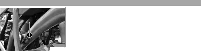
|
LOCATION OF SERIAL NUMBERS |
11 |
Shock4.6 absorber part number
The shock absorber part number is stamped on the top of the shock absorber above the adjusting ring on the engine side.
500129-10

Clutch5.1 lever
The clutch lever is fitted on the left side of the handlebar.
The clutch is hydraulically operated and self-adjusting.
600659-10
Hand5.2 brake lever
Hand brake lever is located on the right side of the handlebar.
The hand brake lever is used to activate the front brake.
400196-10
Short5.3 circuit button (XCF W, SX F)
The short circuit button is fitted on the left side of the handlebar.
Possible states
•Short circuit button  in basic position – In this position, the ignition circuit is closed, and the engine can be started.
•Short circuit button  pressed – In this position, the ignition circuit is interrupted, a running engine stops, and a non-running engine will not start.
500132-10
Short5.4 circuit button (EXC-F, EXC F SIX DAYS)
The short circuit button is fitted on the left side of the handlebar.
Possible states
•Short circuit button  in basic position – In this position, the ignition circuit is closed, and the engine can be started.
•Short circuit button  pressed – In this position, the ignition circuit is interrupted, a running engine stops, and a non-running engine will not start.
500134-10
Emergency5.5 OFF switch (EXC F AUS)
The emergency OFF switch is fitted on the right side of the handlebar.
Possible states
Ignition off – In this position, the ignition circuit is interrupted, a running engine stops, and a non-running engine will not start.
Ignition on – In this position, the ignition circuit is closed, and the engine can be started.
500131-10

Electric5.6 starter button (EXC F EU, EXC F SIX DAYS, XCF W)
The electric starter button is fitted on the right side of the handlebar.
Possible states
•Electric starter button  in basic position
•Electric starter button  pressed – In this position, the electric starter is actuated.
400198-10
Electric5.7 starter button (EXC F AUS)
The electric starter button is fitted on the right side of the handlebar.
Possible states
•Electric starter button  in basic position
•Electric starter button  pressed – In this position, the electric starter is actuated.
500131-11
Light5.8 switch (EXC-F, EXC F SIX DAYS)
500134-12
The light switch is fitted on the left side of the handlebar.
Possible states
Light off – Light switch is turned to the right. In this position, the light is switched off.
Low beam on – Light switch is in the central position. In this position, the low beam and tail light are switched on.
High beam on – Light switch is turned to the left. In this position, the high beam and the tail light are switched on.
Horn5.9 button (EXC-F, EXC F SIX DAYS)
The horn button is fitted on the left side of the handlebar.
Possible states
•Horn button  in neutral position
•Horn button  pressed – The horn is operated in this position.
500134-11
Turn5.10 signal switch (EXC-F, EXC F SIX DAYS)
Turn signal switch is fitted on the left side of the handlebar.
Possible states
Turn signal light off – Turn signal switch is in the central position.
Turn signal light, left, on – Turn signal switch turned to the left.
Turn signal light, right, on – Turn signal switch turned to the right.
500145-10

Overview5.11 of indicator lamps (EXC-F, EXC F SIX DAYS)
Possible states
High beam indicator lamp lights up blue – High beam is switched on.
Turn signal indicator lamp flashes green – Turn signal light is switched on.
500147-01
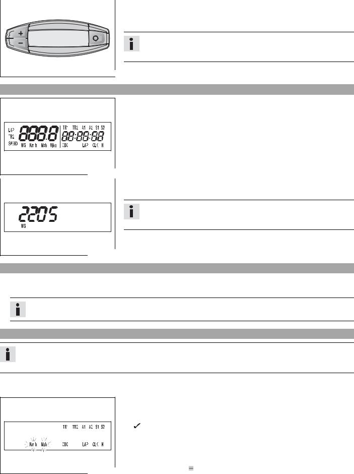
|
CONTROLS (EXC F, EXC F SIX DAYS, XCF-W) |
15 |
||
Speedometer6.1 |
–Press the key  to change the display mode or change to one of the setup menus.
–Press the button  to control different functions.
–Press the button  to control different functions.
Info
In its condition at delivery, the display mode SPEED/H andSPEED/ODO is activated.
Speedometer6.2 activation and test
Activating the speedometer:
The speedometer is activated when one of the keys is pressed or a signal is received from the wheel speed sensor.
Display test
For the function test of the display, all display segments light up briefly.
400313-01
WS (wheel size)
After the display function test, the wheel size WS is displayed briefly.
Info
2205 mm corresponds to the size of the 21″ front wheel with a series production tire.
The display then changes to the last selected mode.
400314-01
Tripmaster6.3 switch
(Option: Tripmaster switch)
You can use the trip master switch to control the functions of the speedometer from the handlebar.
Info
The trip master is an optional accessory.
Setting6.4 kilometers or miles
Info
If you change the unit of measure, the ODO value is retained and converted accordingly.
The values TR1, TR2, A1, A2 and S1 are cleared when the unit of measure is changed.
Condition
The motorcycle is stationary.
–Press the button  briefly and repeatedly until H appears at the bottom right of the display.
–Press the button  for 3 — 5 seconds.
The Setup menu opens and the active functions are displayed.
–Press the button  repeatedly until the Km/h/Mph display flashes.
Adjusting Km/h
– Press the button  .
.
|
Adjusting Mph |
|
|
400329-01 |
– Press the button . |

|
CONTROLS (EXC F, EXC F SIX DAYS, XCF-W) |
16 |
–Press the button  for 3 — 5 seconds.
 The settings are saved and the Setup menu closed.
Info
If no button is pressed for 20 seconds, or if no impulse comes from the wheel speed sensor, the settings are automatically saved and the Setup menu is closed.
Setting6.5 the clock
Condition
The motorcycle is stationary.
–Press the button  briefly and repeatedly until CLK appears at the bottom right of the display.
–Press the button  for 3 — 5 seconds.
The hour display flashes.
– Set the hour display with the button  and/or button
  .
.
– Press the button  briefly.
The next segment of the display flashes and can be set.
–You can set the following segments in the same way as the hours by pressing the
|
400330-01 |
button and the button . |
Info
The seconds can only be set to zero.
–Press the button  for 3 — 5 seconds.
 The settings are saved and the Setup menu closed.
Info
If no button is pressed for 20 seconds, or if no impulse comes from the wheel speed sensor, the settings are automatically saved and the Setup menu is closed.
Adjusting6.6 the speedometer functions
Info
Upon delivery, only the SPEED/H and SPEED/ODO display modes are activated.
Condition
The motorcycle is stationary.
–Press the button  briefly and repeatedly until H appears at the bottom right of the display.
–Press the button  for 3 — 5 seconds.
The Setup menu opens and the active functions are displayed.
– Switch to the function you require by briefly pressing the button  .
.
The selected function flashes.
Activating a function
–Press the button  .
.
|
400318-01 |
The icon remains in the display and the display changes to the next func- |
|
|
tion. |
Deactivating a function
–Press the button  .
.
 The icon disappears from the display and the display changes to the next function.
–Activate or deactivate all functions accordingly.
–Press the button  for 3 — 5 seconds.
 The settings are saved and the Setup menu closed.

|
CONTROLS (EXC F, EXC F SIX DAYS, XCF-W) |
17 |
Info
If no button is pressed for 20 seconds, or if no impulse comes from the wheel speed sensor, the settings are automatically saved and the Setup menu is closed.
Querying6.7 the lap time
Info
This function can be called only if lap times are measured.
Condition
The motorcycle is stationary.
–Press the button  briefly and repeatedly until LAP appears at the bottom right of the display.
–Press the button  briefly.
LAP 1 appears on the left side of the display.
– Laps 1-10 can be displayed by pressing the button  .
.
– The  button has no function
– Press the button  briefly.
Next display mode
400321-01
SPEED6.8 display mode (speed)
400317-02
Info
If an impulse is received from the wheel speed sensor, the left side of the display changes back to the SPEED mode.
–Press the button  briefly and repeatedly until SPEED appears on the left side of the display.
The current speed is displayed in the SPEED display mode.
The current speed can be displayed in Km/h or Mph.
Info
Making the setting according to the country.
When an impulse comes from the front wheel, the left side of the speedometer display changes to the SPEED mode and the current speed is shown.
Display6.9 mode SPEED/H (service hours)
400316-01
Condition
•The motorcycle is stationary
–Press the button  briefly and repeatedly until H appears at the bottom right of the display.
In display mode H, the service hours of the engine are displayed.
The service hour counter stores the total traveling time.
Info
The service hour counter is necessary for ensuring that maintenance work is carried out at the right intervals.
If the speedometer is in H display mode at the start of the journey, it automatically changes to the ODO display mode.
The H display mode is suppressed during the journey.
|
Press the button . |
No function |
|
Press the button . |
No function |
|
Press the button |
The display changes to the Setup menu of the speedometer |
|
for 3 — 5 seconds. |
functions. |
|
Press the button |
Next display mode |
|
briefly. |
|

|
CONTROLS (EXC F, EXC F SIX DAYS, XCF-W) |
18 |
Display6.10 mode SPEED/CLK (clock)
400319-01
Display6.11 mode SPEED/LAP (lap time)
400320-01
Display6.12 mode SPEED/ODO (odometer)
400317-01
–Press the button  briefly and repeatedly until CLK appears at the bottom right of the display.
The time is displayed in CLK display mode.
|
Press the button . |
No function |
|
Press the button . |
No function |
|
Press the button |
The display changes to the Setup menu of the clock. |
|
for 3 — 5 seconds. |
|
|
Press the button |
Next display mode |
|
briefly. |
|
–Press the button  briefly and repeatedly until LAP appears at the bottom right of the display.
In the LAP display mode, up to 10 lap times can be timed with the stop watch.
Info
If the lap time continues after you press the button  , 9 memory locations are already occupied.
Lap 10 must be timed with the button  .
.
|
Press the button . |
Starts or stops the clock. |
|
Press the button . |
Stops the current lap time and saves it, and the stop watch |
|
starts the next lap. |
|
|
Press the button |
The stop watch and the lap time are reset. |
|
for 3 — 5 seconds. |
|
|
Press the button |
Next display mode |
|
briefly. |
|
–Press the button  briefly and repeatedly until ODO appears at the bottom right of the display.
In ODO display mode, the total number of kilometers ridden is displayed.
|
Press the button . |
No function |
|
Press the button . |
No function |
|
Press the button |
– |
|
for 3 — 5 seconds. |
|
|
Press the button |
Next display mode |
|
briefly. |
|
Display6.13 mode SPEED/TR1 (trip master 1)
–Press the button  briefly and repeatedly until TR1 appears at the top right of the display.
TR1 (trip master 1) runs constantly and counts up to 999.9.
You can use it to measure trips or the distance between refuelling stops.
TR1 is coupled with A1 (average speed 1) and S1 (stop watch 1).
Info
If 999.9 is exceeded, the values of TR1, A1 and S1 are automaticallt reset to
0.0.
400323-01
|
Press the button . |
No function |
|
Press the button . |
No function |
|
Press the button |
Displays of TR1, A1 and S1 are reset to 0,0. |
|
for 3 — 5 seconds. |
|
![]()
|
CONTROLS (EXC F, EXC F SIX DAYS, XCF-W) |
19 |
|||
|
Press the button |
Next display mode |
|||
|
briefly. |
||||
Display6.14 mode SPEED/TR2 (trip master 2)
–Press the button  briefly and repeatedly until TR2 appears at the top right of the display.
TR2 (trip master 2) runs constantly and counts up to 999.9.
The displayed value can be set manually with the button  and the button
  . A very practical function when riding using the road book.
|
Info |
||||||||
|
The TR2 value can also be corrected manually during the journey with the but- |
||||||||
|
ton and the button . |
||||||||
|
400324-01 |
If 999.9 is exceeded, the value of TR2 is automatically reset to 0.0. |
|||||||
|
Press the button . |
Increases value of TR2. |
|
Press the button . |
Reduces value of TR2. |
|
Press the button |
Deletes value of TR2. |
|
for 3 — 5 seconds. |
|
|
Press the button |
Next display mode |
|
briefly. |
|
Disply6.15 mode SPEED/A1 (average speed 1)
–Press the button  briefly and repeatedly until A1 appears at the top right of the display.
A1 (average speed 1) shows the average speed calculated using TR1 (trip master 1) and S1 (stop watch 1).
The calculation of this value is activated by the first impulse of the wheel speed sensor and ends 3 seconds after the last impulse.
|
Press the button . |
No function |
|||||
|
Press the button . |
No function |
|||||
|
400325-01 |
Press the button |
Displays of TR1, A1 and S1 are reset to 0,0. |
||||
|
for 3 — 5 seconds. |
||||||
|
Press the button |
Next display mode |
|||||
|
briefly. |
||||||
Display6.16 mode SPEED/A2 (average speed 2)
–Press the button  briefly and repeatedly until A2 appears at the top right of the display.
A2 (average speed 2) shows the average speed on the basis of the current speed if the stop watch S2 (stop watch 2) is running.
Info
The displayed value can differ from the actual average speed if S2 was not timed after the ride.
400326-01
|
Press the button . |
No function |
|
Press the button . |
No function |
|
Press the button |
– |
|
for 3 — 5 seconds. |
|
|
Press the button |
Next display mode |
|
briefly. |
|

|
CONTROLS (EXC F, EXC F SIX DAYS, XCF-W) |
20 |
Display6.17 mode SPEED/S1 (stop watch 1)
400327-01
–Press the button  briefly and repeatedly until S1 appears at the top right of the display.
S1 (stop watch 1) displays the journey time on the basis of TR1 and continues when an impulse is received from the wheel speed sensor.
The calculation of this value starts with the first impulse of the wheel speed sensor and ends 3 seconds after the last impulse.
|
Press the button . |
No function |
|
Press the button . |
No function |
|
Press the button |
Displays of TR1, A1 and S1 are reset to 0,0. |
|
for 3 — 5 seconds. |
|
|
Press the button |
Next display mode |
|
briefly. |
|
Display6.18 mode SPEED/S2 (stop watch 2)
|
– Press the button |
briefly and repeatedly until S2 appears at the top right of the |
|||||||
|
display. |
||||||||
|
S2 (stop watch 2) is a manual stop watch. |
||||||||
|
If S2 is running in the background, the S2 display flashes in the speedometer display. |
||||||||
|
Press the button . |
Starts or stops S2. |
|||||||
|
Press the button . |
No function |
|||||||
|
Press the button |
Displays of S2 and A2 are reset to 0.0. |
|||||||
|
400328-01 |
for 3 — 5 seconds. |
|||||||
|
Press the button |
Next display mode |
|||||||
|
briefly. |
||||||||
Table of functions
|
Display |
Press the button . |
Press the button . |
Press the button for 3 — |
Press the button |
||
|
5 seconds. |
briefly. |
|||||
|
Display mode SPEED/H |
No function |
No function |
The display changes to |
Next display mode |
||
|
(service hours) |
the Setup menu of the |
|||||
|
speedometer functions. |
||||||
|
Display mode SPEED/CLK |
No function |
No function |
The display changes to |
Next display mode |
||
|
(clock) |
the Setup menu of the |
|||||
|
clock. |
||||||
|
Display mode SPEED/LAP |
Starts or stops the |
Stops the current lap |
The stop watch and the |
Next display mode |
||
|
(lap time) |
clock. |
time and saves it, and |
lap time are reset. |
|||
|
the stop watch starts |
||||||
|
the next lap. |
||||||
|
Display mode |
No function |
No function |
– |
Next display mode |
||
|
SPEED/ODO (odometer) |
||||||
|
Display mode SPEED/TR1 |
No function |
No function |
Displays of TR1, A1 and |
Next display mode |
||
|
(trip master 1) |
S1 are reset to 0,0. |
|||||
|
Display mode SPEED/TR2 |
Increases value of TR2. |
Reduces value of TR2. |
Deletes value of TR2. |
Next display mode |
||
|
(trip master 2) |
||||||
|
Disply mode SPEED/A1 |
No function |
No function |
Displays of TR1, A1 and |
Next display mode |
||
|
(average speed 1) |
S1 are reset to 0,0. |
|||||
|
Display mode SPEED/A2 |
No function |
No function |
– |
Next display mode |
||
|
(average speed 2) |
||||||
|
Display mode SPEED/S1 |
No function |
No function |
Displays of TR1, A1 and |
Next display mode |
||
|
(stop watch 1) |
S1 are reset to 0,0. |
|||||
|
Display mode SPEED/S2 |
Starts or stops S2. |
No function |
Displays of S2 and A2 |
Next display mode |
||
|
(stop watch 2) |
are reset to 0.0. |
|||||
|
Table of conditions and activability |
||||||
|
Display |
The motorcycle is |
Menu can be acti- |
||||
|
stationary |
vated |
|||||
|
Display mode SPEED/H (service hours) |
• |
|||||
|
CONTROLS (EXC F, EXC F SIX DAYS, XCF-W) |
21 |
|||
|
Table of conditions and activability |
||||
|
Display |
The motorcycle is |
Menu can be acti- |
||
|
stationary |
vated |
|||
|
Display mode SPEED/CLK (clock) |
• |
|||
|
Display mode SPEED/LAP (lap time) |
• |
|||
|
Display mode SPEED/TR1 (trip master 1) |
• |
|||
|
Display mode SPEED/TR2 (trip master 2) |
• |
|||
|
Disply mode SPEED/A1 (average speed 1) |
• |
|||
|
Display mode SPEED/A2 (average speed 2) |
• |
|||
|
Display mode SPEED/S1 (stop watch 1) |
• |
|||
|
Display mode SPEED/S2 (stop watch 2) |
• |
|||

Fuel7.1 tap (EXC F, EXC F SIX DAYS, XCF-W)
The fuel tap is on the left side of the fuel tank.
Using tap handle on the fuel tap, you can open or close the supply of fuel to the carburetor.
Possible states
•Fuel supply closed OFF – No fuel can flow from the tank to the carburetor.
•Fuel supply open ON – Fuel can flow from the tank to the carburetor. The fuel tank empties down to the reserve.
•Reserve fuel supply open RES – Fuel can flow from the tank to the carburetor. The fuel tank empties completely.
500137-10
Fuel7.2 tap (SX F)
The fuel tap is on the left side of the fuel tank.
Using tap handle on the fuel tap, you can open or close the supply of fuel to the carburetor.
Possible states
•Fuel supply closed OFF – No fuel can flow from the tank to the carburetor.
•Fuel supply open ON – Fuel can flow from the tank to the carburetor. The fuel tank empties completely.
500178-10
Opening7.3 filler cap
–Press release button , turn filler cap counterclockwise and lift it upwards and remove.
400199-10
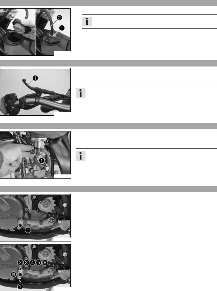
Closing7.4 filler cap
–Replace the filler cap and turn clockwise until the release button locks in place.
Info
Route the fuel tank breather hose without kinking.
400199-11
Choke7.5 (EXC-F EU, EXC F SIX DAYS)
500136-10
The choke lever is fitted on the left side of the handlebar.
Activating the choke function frees an opening through which the engine can draw extra fuel. This gives a richer fuel-air mixture, which is needed for a cold start.
Info
If the engine is warm, the choke function must be deactivated.
Possible states
•Choke function activated – The choke lever is pulled to the stop.
•Choke function deactivated – The choke lever is pushed back to the stop.
Choke7.6 (XCF W, SX F, EXC F AUS)
600660-10
Choke is fitted on the left side of the carburetor.
Activating the choke function frees an opening through which the engine can draw extra fuel. This gives a richer fuel-air mixture, which is needed for a cold start.
Info
If the engine is warm, the choke function must be deactivated.
Possible states
•Choke function activated – The choke lever is pulled out to the stop.
•Choke function deactivated – The choke lever is pushed in to the stop.
Shift7.7 lever
Shift lever is mounted on the left side of the engine.
600661-13
The gear positions can be seen in the photograph.
The neutral or idle position is between the first and second gears.
600661-10

Foot7.8 brake lever
Foot brake lever is located in front of the right footrest.
The foot brake lever is used to activate the rear brake.
600664-10
Kick7.9 starter
600664-11
The kick starter is fitted on the right of the engine.
The engine can be started with either the kick starter or the electric starter. The upper part of the kick starter can be swung out.
Info
Before riding, swing the upper part of the kick starter inwards towards the engine.
Side7.10 stand (EXC F, EXC F SIX DAYS, XCF-W)
|
Note |
|||
|
Danger of damage The parked vehicle can roll away or fall over. |
|||
|
– Always place the vehicle on a firm and even surface. |
|||
|
Note |
|||
|
Material damage Damage and destruction of components by excessive load. |
|||
|
– The side stand is designed for the weight of the motorcycle only. Do not sit on the |
|||
|
motorcycle when it is supported by the side stand only. The side stand and/or the |
|||
|
500140-10 |
frame could be damaged and the motorcycle could fall over. |
||
|
To park the motorcycle, press the side stand to the ground with your foot and lean |
|||
|
the motorcycle on it. |
|||
|
When you are riding, the side stand must be folded up and secured with the rubber |
|||
|
band . |
600665-10
|
Plug7.11 |
-in stand (SX F) |
||||||
|
Note |
|||||||
|
Danger of damage The parked vehicle can roll away or fall over. |
|||||||
|
– Always place the vehicle on a firm and even surface. |
|||||||
|
To park the motorcycle, insert plug-in stand into the left side of the wheel spindle. |
|||||||
|
Info |
|||||||
|
Remove the plug-in stand before starting on a trip. |
|||||||
|
400203-10 |
|||||||

Steering7.12 lock (EXC-F, EXC F SIX DAYS)
Steering lock is fitted on the left side of the steering head.
The steering lock is used to lock the steering. Steering, and therefore riding, is no longer possible.
500126-10
Locking7.13 the steering (EXC-F, EXC F SIX DAYS)
Note
Danger of damage The parked vehicle can roll away or fall over.
–Always place the vehicle on a firm and even surface.
–Park the vehicle.
–Turn the handlebar as far as possible to the right.
–Insert the key in the steering lock, turn it to the left, press it in and turn it to the right. Remove the key.
 Steering is no longer possible.
Info
Never leave the key in the steering lock.
400732-01
Unlocking7.14 the steering (EXC-F, EXC F SIX DAYS)
–Insert the key in the steering lock, turn it to the left, pull it out and turn it to the right. Remove the key.
 You can now steer the bike again.
Info
Never leave the key in the steering lock.
400731-01

GENERAL TIPS AND HINTS ON PUTTING INTO OPERATION |
26 |
Advice8.1 on first use
Danger
Danger of accidents Danger arising from the rider’s judgement being impaired.
–Do not use the vehicle if you are inexperienced or if you have consumed alcohol or drugs.
Warning
Risk of injury Missing or poor protective clothing present an increased safety risk.
–Wear protective clothing (helmet, boots, gloves, pants and jacket with protectors) every time you ride the vehicle. Always wear protective clothing, which must be undamaged and meet legal requirements.
Warning
Danger of crashing Poor vehicle handling due to different tire tread patterns on front and rear wheels.
–The front and rear wheels must be fitted with tires with similar tread patterns to prevent loss of control over the vehicle.
Warning
Danger of accidents Critical handling characteristic due to inappropriate riding style.
–Adapt your riding speed to the road conditoins and your riding ability.
Warning
Danger of accidents Accident risk caused by presence of a passenger.
–Your vehicle is not designed to carry passengers. Do not ride with a passenger.
Warning
Danger of accidents Failure of brake system.
–If the foot brake lever is not released, the brake linings drag permanently. The rear brake can fail due to overheating. Take your foot off the foot brake lever if you do not want to brake.
Warning
Danger of accidents Unstable riding behavior.
–Do not exceed the maximum permissible weight and axle loads.
Warning
Risk of misappropriation Usage by unauthorized persons.
–Never leave the vehicle while the engine is running. Secure the vehicle against use by unauthorized persons.
Info
When using your motorcycle, remember that others may feel disturbed by excessive noise.
–Make sure that the pre-delivery inspection work has been carried out by an authorized KTM workshop. You receive a delivery certificate and the service record at vehicle handover.
–Before your first trip, read the entire operating instructions carefully.
–Get to know the controls.
–Adjust the basic position of clutch lever. ( p. 83)
(XCF W, SX F)
–adjust the basic position of hand brake lever. ( p. 62)
(EXC-F, EXC F SIX DAYS)
– Adjust the free travel of the hand brake lever. ( p. 62)
–Adjust the basic position of the footbrake lever. x( p. 66)
–Adjust the basic position of the shift lever. x( p. 84)
–Get used to handling the motorcycle on a suitable piece of land before making a longer trip.
Info
Offroad, you should be accompanied by another person on another machine so that you can help each other.
–Try also to ride as slowly as possible and in a standing position to get a better feeling for the vehicle.
–Do not make any offroad trips that over-stress your ability and experience.
–Hold the handlebar firmly with both hands and keep your feet on the footrests when riding.
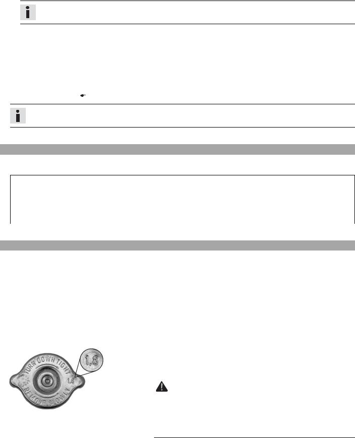
|
GENERAL TIPS AND HINTS ON PUTTING INTO OPERATION |
27 |
(EXC F, EXC F SIX DAYS, XCF-W)
–If you carry any baggage, make sure it is fixed firmly as close as possible to the center of the vehicle and ensure even weight distribution between the front and rear wheels.
Info
Motorcycles react sensitively to any changes of weight distribution.
(SX F)
– Do not transport luggage.
–Do not exceed the overall maximum permitted weight and the axle loads. Guideline
|
Maximum permissible overall weight |
335 kg (739 lb.) |
|
|
Maximum permissible front axle load |
145 kg (320 lb.) |
|
|
Maximum permissible rear axle load |
190 kg (419 lb.) |
|
|
– Check the spoke tension. ( p. 73) |
Info
The spoke tension must be checked after half an hour of operation.
–Run the engine in.
Running8.2 -in the engine
–During the running-in phase, do not exceed the specified engine speed and engine performance. Guideline
Maximum engine speed
|
During the first 3 service hours |
7,000 rpm |
|
Maximum engine performance |
|
|
During the first 3 service hours |
≤ 50 % |
|
During the next 12 service hours |
≤ 75 % |
– Avoid fully opening the throttle!
Preparing8.3 vehicle for arduous riding conditions
–Using a motorcycle in arduous conditions can lead to excessive wear of components such as the power train or brakes. For this reason, it may be necessary to service or replace worn parts before the limit specified in the service schedule is reached.
Arduous riding conditions are:
–Riding on dry sand. ( p. 27)
–Riding on wet sand. ( p. 28)
–Riding on wet and muddy surfaces. ( p. 29)
–Rides at high temperature and slow speed. ( p. 30)
–Rides at low temperatures or in snow. ( p. 30)
|
Preparing8.4 |
for riding on dry sand |
||||||
|
– Check the radiator cap. |
|||||||
|
Value on radiator cap |
1.8 bar (26 psi) |
||||||
|
» If the displayed value does not correspond to specifications: |
|||||||
|
Warning |
|||||||
|
Danger of scalding During motorcycle operation, the coolant gets |
|||||||
|
very hot and is under pressure. |
|||||||
|
– Do not remove the radiator cap, radiator hoses or other cooling |
|||||||
|
600872-10 |
system components when the engine is hot. Allow the engine |
||||||
|
and cooling system to cool down. In case of scalding, rinse |
|||||||
|
immediately with lukewarm water. |
– Change the radiator cap.
– Seal the air filter box. x

|
GENERAL TIPS AND HINTS ON PUTTING INTO OPERATION |
28 |
600869-01
600871-01
600868-01
Tip
Seal the air filter box on the edges against dirt.
–Clean the air filter. x( p. 82)
Info
Check the air filter approx. every 30 minutes.
–Fit a dust protection device on the air filter.
Dust protection device for air filter (59006019000)
Info
See the KTM PowerParts fitting instructions.
–Fit a sand screen device on the air filter.
Sand protection device for air filter (59006022000)
Info
See the KTM PowerParts fitting instructions.
–Adjust the carburetor jetting and settings.
Info
Your authorized KTM workshop has the recommended carburetor tuning settings.
–Clean the chain.
Chain cleaner ( p. 117)
–Fit the steel sprocket.
Tip
Do not grease the chain.
–Clean radiator fins.
–Straighten bent radiator fins carefully.
|
Preparing8.5 |
for riding on wet sand |
||||||||||
|
– Check the radiator cap. |
|||||||||||
|
Value on radiator cap |
1.8 bar (26 psi) |
||||||||||
|
» If the displayed value does not correspond to specifications: |
|||||||||||
|
Warning |
|||||||||||
|
Danger of scalding During motorcycle operation, the coolant gets |
|||||||||||
|
very hot and is under pressure. |
|||||||||||
|
– Do not remove the radiator cap, radiator hoses or other cooling |
|||||||||||
|
600872-10 |
system components when the engine is hot. Allow the engine |
||||||||||
|
and cooling system to cool down. In case of scalding, rinse |
|||||||||||
|
immediately with lukewarm water. |
|||||||||||
|
– Change the radiator cap. |
|||||||||||
|
– Seal the air filter box. x |
|||||||||||
|
Tip |
|||||||||||
|
Seal the air filter box on the edges against dirt. |
|||||||||||
|
– |
|||||||||||
|
Clean the air filter. x( |
p. 82) |
![]()
|
GENERAL TIPS AND HINTS ON PUTTING INTO OPERATION |
29 |
Info
Check the air filter approx. every 30 minutes.
–Fit a waterproofing device on the air filter. Waterproofing device for air filter (59006021000)
Info
See the KTM PowerParts fitting instructions.
–Adjust the carburetor jetting and settings.
Info
Your authorized KTM workshop has the recommended carburetor tuning settings.
–Clean the chain.
Chain cleaner ( p. 117)
–Fit the steel sprocket.
Tip
Do not grease the chain.
–Clean radiator fins.
–Straighten bent radiator fins carefully.
Preparing8.6 for riding on wet and muddy surfaces
–Seal the air filter box. x
Tip
Seal the air filter box along the edges to prevent the ingress of dirt.
–Clean the air filter. x( p. 82)
Info
Check the air filter approx. every 30 minutes.
–Fit a waterproofing device on the air filter. Waterproofing device for air filter (59006021000)
Info
See the KTM PowerParts fitting instructions.
–Adjust the carburetor jetting and settings.
|
Info |
||||||
|
600870-01 |
Your authorized KTM workshop has the recommended carburetor tuning set- |
|||||
|
tings. |
–Fit the steel sprocket.
–Clean the motorcycle. ( p. 93)
–Straighten bent radiator fins carefully.
600868-01

|
GENERAL TIPS AND HINTS ON PUTTING INTO OPERATION |
30 |
|||
|
Preparing8.7 |
for rides at high temperature and slow speed |
–Check the radiator cap.
|
Value on radiator cap |
1.8 bar (26 psi) |
»If the displayed value does not correspond to specifications:
Warning
Danger of scalding During motorcycle operation, the coolant gets very hot and is under pressure.
–Do not remove the radiator cap, radiator hoses or other cooling system components when the engine is hot. Allow the engine and cooling system to cool down. In case of scalding, rinse immediately with lukewarm water.
–Change the radiator cap.
–Seal the air filter box. x
Tip
Seal the air filter box on the edges against dirt.
–Clean the air filter. x( p. 82)
Info
Check the air filter approx. every 30 minutes.
–Adjust the secondary drive to the road conditions.
Info
The engine oil quickly gets hot if the clutch has to be operated very often due to an excessively high secondary drive.
–Clean the chain.
Chain cleaner ( p. 117)
–Clean radiator fins.
–Straighten bent radiator fins carefully.
–Check the coolant level. ( p. 79)
Preparing8.8 for rides at low temperatures or in snow
–Seal the air filter box. x
Tip
Seal the air filter box on the edges against dirt.
–Clean the air filter. x( p. 82)
Info
Check the air filter approx. every 30 minutes.
–Fit a waterproofing device on the air filter. Waterproofing device for air filter (59006021000)
Info
See the KTM PowerParts fitting instructions.
–Adjust the carburetor jetting and settings.
|
Info |
||||||
|
600870-01 |
Your authorized KTM workshop has the recommended carburetor tuning set- |
|||||
|
tings. |
||||||

Checks9.1 before putting into operation
Info
Make sure that the motorcycle is in a perfect technical condition before use.
Info
In the interests of riding safety, make a habit of making a general check before you ride.
–Check the engine oil level. ( p. 87)
–Check the chain tension. ( p. 57)
–Check for chain dirt accumulation. ( p. 56)
–Check the tire condition. ( p. 72)
–Check the tire air pressure. ( p. 73)
–Check the brake fluid level of the front brake. ( p. 62)
–Check the rear brake fluid level. ( p. 66)
–Check the front brake linings. ( p. 64)
–Check the rear brake linings. ( p. 67)
–Check the brake system function.
–Check the coolant level. ( p. 79)
–Check the settings of all controls and ensure that they can be operated smoothly.
–Check the functioning of the electrical equipment.
Starting9.2
Danger
Danger of poisoning Exhaust gases are poisonous and inhaling them may result in unconsciousness and/or death.
–When running the engine, always make sure there is sufficient ventilation, and do not start or run the engine in an enclosed space without an effective exhaust extraction system.
Note
Engine failure High engine speeds in cold engines have a negative effect on the service life of the engine.
–Always warm up the engine at low engine speeds.
Info
If the motorcycle is unwilling to start, the cause can be old fuel in the float chamber. The flammable elements of the fuel evaporate after a long time of standing.
If the float chamber is filled with fresh fuel, the engine starts immediately.
Press the starter for a maximum of 5 seconds. Wait for a least 5 seconds until trying again.
Engine has been out of use for more than 1 week
–Empty the carburetor float chamber. x( p. 86)
(EXC F, EXC F SIX DAYS, XCF-W)
–Turn handle of the fuel tap to the ON position. (Figure 500137-10 p. 22)
Fuel can flow from the fuel tank to the carburetor.
(SX F)
–Turn handle of the fuel tap to the ON position. (Figure 500178-10 p. 22)
|
Fuel can flow from the fuel tank to the carburetor. |
|||
|
– |
Remove the motorcycle from the stand. |
||
|
400733-01 |
|||
|
– |
Shift transmission to neutral. |
(EXC F AUS)
–Turn the emergency OFF switch to the position  .
.
The engine is cold
(XCF W, SX F, EXC F AUS)
–Pull choke lever out as far as possible.
(EXC-F EU, EXC F SIX DAYS)
–Pull the choke lever to the stop.

–Press the electric starter button or press the kickstarter robustly through its full range.
Info
Do not open the throttle.
Starting9.3 up
Info
If your bike has lights, switch them on before riding. You will then be seen earlier by other motorists.
When you are riding, the side stand must be folded up and secured with the rubber band.
–Pull the clutch lever, engage 1st gear, release the clutch lever slowly and simultaneously open the throttle carefully.
Shifting,9.4 riding
Warning
Danger of accidents If you change down at high engine speed, the rear wheel can lock up.
–Do not change into a low gear at high engine speed. The engine overspeeds and the rear wheel can block.
Info
If you hear unusual noises while riding, stop immediately, switch off the engine and contact an authorized KTM workshop. First gear is used for starting off or for steep inclines.
–When conditions allow (incline, road situation, etc.), you can shift into a higher gear. To do so, release the throttle while simultaneously pulling the clutch lever, shift into the next gear, release the clutch and open the throttle.
–If the choke function was activated, deactivate it after the engine has warmed up.
–When you reach maximum speed after fully opening the throttle, turn back the throttle to about ¾ of its range. This barely reduces vehicle speed but lowers fuel consumption considerably.
–Always open the throttle only as much as the engine can handle – abrupt throttle opening increases fuel consumption.
–To shift down, brake and close the throttle at the same time.
–Pull the clutch lever and shift into a lower gear, release the clutch lever slowly and open the throttle or shift again.
–Switch off the engine if you expect to be stationary for a long time. Guideline
≥2 min
–Avoid frequent and prolonged slipping of the clutch. This causes heat build-up in the engine oil, the engine and the cooling system.
–Ride at lower engine speeds instead of high revs and a slipping clutch.
Braking9.5
Warning
Danger of accidents If you brake too hard, the wheels can lock.
–Adapt your braking to the traffic situation and the road conditions.
Warning
Danger of accidents Reduced braking efficiency caused by spongy pressure point of front or rear brake.
–Check the brake system and do not continue riding. (Your authorized KTM workshop will be glad to help.)
Warning
Danger of accidents Reduced braking efficiency due to wet or dirty brakes.
–Clean or dry dirty or wet brakes by riding and braking gently.
–On sandy, wet or slippery surfaces, use the rear brake.
–Braking should always be completed before you go into a bend. Change down to a lower gear appropriate to your road speed.
–On long downhill stretches, use the braking effect of the engine. Change down one or two gears, but do not overstress the engine. In this way, you have to brake far less and the brakes do not overheat.

Stopping,9.6 parking
Warning
Risk of misappropriation Usage by unauthorized persons.
–Never leave the vehicle while the engine is running. Secure the vehicle against use by unauthorized persons.
Warning
Danger of burns Some vehicle components get very hot when the vehicle is in use.
–Do not touch hot components such as exhaust system, radiator, engine, shock absorber and brakes. Allow these components to cool down before starting work on them.
Note
Danger of damage The parked vehicle can roll away or fall over.
–Always place the vehicle on a firm and even surface.
Note
Fire hazard Some vehicle components become very hot when the vehicle is operated.
–Do not park the vehicle near flammable or explosive substances. Do not place objects on the vehicle while it is still warm from being run. Always let the vehicle cool first.
Note
Material damage Damage and destruction of components by excessive load.
–The side stand is designed for the weight of the motorcycle only. Do not sit on the motorcycle when it is supported by the side stand only. The side stand and/or the frame could be damaged and the motorcycle could fall over.
–Brake the motorcycle.
–Shift transmission to neutral.
(XCF W, SX F)
–Press and hold the short circuit button  while the engine is idling until the engine stops.
(EXC-F, EXC F SIX DAYS)
–Press and hold the short circuit button  while the engine is idling until the engine stops.
(EXC F, EXC F SIX DAYS, XCF-W)
–Turn handle of the fuel tap to the OFF position. (Figure 500137-10 p. 22)
(SX F)
– Turn handle of the fuel tap to the OFF position. (Figure 500178-10 p. 22)
–Park the motorcycle on firm ground.
Refueling9.7
Danger
Fire hazard Fuel is highly flammable.
–Never refuel the vehicle near open flames or burning cigarettes, and always switch off the engine first. Be careful that no fuel is spilt, especially on hot vehicle components. Clean up spilt fuel immediately.
–Fuel in the fuel tank expands when warm and can escape if the tank is overfilled. See the notes on refueling.
Warning
Danger of poisoning Fuel is poisonous and a health hazard.
–Avoid contact of the fuel with skin, eyes and clothing. Do not inhale fuel vapors. If fuel gets into your eyes, rinse immediately with water and contact a doctor. Wash affected skin areas immediately with soap and water. If fuel is swallowed, contact a doctor immediately. Change clothing that has come into contact with fuel.
Warning
Environmental hazard Improper handling of fuel is a danger to the environment.
–Do not allow fuel to get into the ground water, the ground, or the sewage system.
–Switch off engine.
–Open the filler cap. ( p. 22)

RIDING INSTRUCTIONS
A
400382-10
34
–Fill the fuel tank with fuel up to measurement . Guideline
|
Measurement of |
35 mm (1.38 in) |
||
|
Total fuel tank |
9.2 l |
Super unleaded (ROZ 95 / RON 95 / |
|
|
capacity, |
(2.43 US gal) |
PON 91) ( |
p. 116) |
|
approx. (EXC F, |
|||
|
EXC F SIX DAYS, |
|||
|
XCF-W) |
|||
|
Total fuel tank |
8.0 l |
Super unleaded (ROZ 95 / RON 95 / |
|
|
capacity, approx. |
(2.11 US gal) |
PON 91) ( |
p. 116) |
|
(SX F) |
|||
–Close the filler cap. ( p. 23)

|
SERVICE SCHEDULE (EXC F, EXC F SIX DAYS, XCF-W) |
35 |
|||||||||||
|
Important10.1 |
maintenance work to be carried out by an authorized KTM workshop |
|||||||||||
|
S3N |
S20A |
S30A |
||||||||||
|
Engine |
Change the engine oil and oil filter, clean the oil screen. x( p. 87) |
• |
• |
|||||||||
|
Replace the spark plug. |
• |
|||||||||||
|
Check the valve clearance. x |
• |
• |
||||||||||
|
Check the engine mounting screws for tightness. |
• |
• |
||||||||||
|
Clean the spark plug connectors and check for tightness. |
• |
• |
||||||||||
|
Check that the screws in the shift lever and the kickstarter are tight. |
• |
• |
||||||||||
|
Carburetor |
Check the carburetor connection boots for cracks and leakage. |
• |
||||||||||
|
Check the vent hoses for damage and routing without sharp bends. |
• |
• |
||||||||||
|
Check the idle. |
• |
• |
||||||||||
|
Attachments |
Check the cooling system for leakage. |
• |
• |
|||||||||
|
Check the anti-freeze and coolant level. ( |
p. 79) |
• |
• |
|||||||||
|
Check the exhaust system for leakage and looseness. |
• |
|||||||||||
|
Check the throttle cables for damage, smooth operation and routing without sharp |
• |
• |
||||||||||
|
bends. |
||||||||||||
|
Check the fluid level of the hydraulic clutch. ( |
p. 83) |
• |
• |
|||||||||
|
Clean the air filter. x( |
p. 82) |
• |
• |
|||||||||
|
Check the cables for damage and routing without sharp bends. |
• |
|||||||||||
|
Check the functioning of the electrical equipment. |
• |
• |
||||||||||
|
Check the headlight setting. |
• |
|||||||||||
|
Brakes |
Check the front brake linings. ( |
p. 64) |
• |
• |
||||||||
|
Check the rear brake linings. ( |
p. 67) |
• |
• |
|||||||||
|
Check the brake discs. ( |
p. 61) |
• |
• |
|||||||||
|
Check the brake fluid level of the front brake. ( |
p. 62) |
• |
• |
|||||||||
|
Check the rear brake fluid level. ( p. 66) |
• |
• |
||||||||||
|
Check the brake lines for damage and leakage. |
• |
• |
||||||||||
|
Check the free travel of the hand brake lever. ( |
p. 61) |
• |
• |
|||||||||
|
Check the free travel of the foot brake lever. ( |
p. 66) |
• |
• |
|||||||||
|
Check the brake system function. |
• |
• |
||||||||||
|
Check the screws and guide bolts of the rake system for tightness. |
• |
• |
||||||||||
|
Chassis |
Check the shock absorber and fork for leakage and functioning. x |
• |
• |
|||||||||
|
Clean the dust boots of the fork legs. ( |
p. 48) |
• |
||||||||||
|
Bleed fork legs. ( |
p. 48) |
• |
||||||||||
|
Check the frame and swingarm for damage. |
• |
|||||||||||
|
Check the swingarm bearing. |
• |
|||||||||||
|
Check the steering head bearing play. ( |
p. 49) |
• |
• |
|||||||||
|
Check all screws to see if they are tight. |
• |
• |
||||||||||
|
Wheels |
Check the spoke tension. ( |
p. 73) |
• |
• |
||||||||
|
Check the wheel hubs for damage. |
• |
|||||||||||
|
Check the rim run-out. |
• |
• |
||||||||||
|
Check the tire condition. ( |
p. 72) |
• |
• |
|||||||||
|
Check the tire air pressure. ( |
p. 73) |
• |
• |
|||||||||
|
Check the chain wear. ( |
p. 58) |
• |
• |
|||||||||
|
Check the chain tension. ( |
p. 57) |
• |
• |
|||||||||
|
Clean the chain. ( |
p. 56) |
• |
• |
|||||||||
|
Check the wheel bearing for play. |
• |
• |
||||||||||
|
Clean and grease the adjusting screws of the chain adjuster. |
• |
• |
||||||||||
|
S3N: once after three operating hours |
S20A: every 20 service hours / after every race
S30A: every 30 service hours

|
SERVICE SCHEDULE (EXC F, EXC F SIX DAYS, XCF-W) |
36 |
Important10.2 maintenance work to be carried out by an authorized KTM workshop (as additional order)
|
Competition use |
Hobby use |
S10N |
J1A |
|||||||
|
S10A |
S20A |
S40A |
S80A |
S20A |
S40A |
S60A |
S80A |
|||
|
Perform a fork service. (EXC F, |
• |
• |
• |
• |
• |
|||||
|
EXC F SIX DAYS, XCF-W) x |
||||||||||
|
Perform a shock absorber service. |
• |
• |
• |
|||||||
|
(EXC F, EXC F SIX DAYS, XCF-W) x |
||||||||||
|
Grease the steering head bearing. x |
• |
|||||||||
|
Treat electric contacts with contact |
• |
|||||||||
|
spray. |
||||||||||
|
Change the hydraulic clutch fluid. x |
• |
|||||||||
|
( p. 83) |
||||||||||
|
Change the front brake fluid. x |
• |
|||||||||
|
Change the rear brake fluid. x |
• |
|||||||||
|
Check the clutch discs for wear. x |
• |
• |
• |
• |
• |
|||||
|
Check the clutch. x |
• |
• |
• |
• |
• |
|||||
|
Check the cylinder and piston for |
• |
• |
• |
|||||||
|
wear. x |
||||||||||
|
Check the camshafts. x |
• |
• |
• |
|||||||
|
Check the valve spring seat. x |
• |
• |
• |
|||||||
|
Check the valves. x |
• |
• |
• |
|||||||
|
Change the valves. x |
• |
• |
||||||||
|
Check wear of valve guides. x |
• |
• |
||||||||
|
Change the valve springs. x |
• |
• |
• |
|||||||
|
Check the timing-chain tensioner |
• |
• |
• |
|||||||
|
function. x |
||||||||||
|
Check the crankshaft run-out at the |
• |
• |
• |
|||||||
|
bearing pin. x |
||||||||||
|
Change the conrod bearing. x |
• |
• |
• |
|||||||
|
Change the crankshaft main bear- |
• |
• |
||||||||
|
ing. x |
||||||||||
|
Fully check the transmission. x |
• |
• |
• |
|||||||
|
Check the shift mechanism. x |
• |
• |
• |
|||||||
|
Check the spring length of the oil pres- |
• |
• |
• |
|||||||
|
sure regulator valve. x |
||||||||||
|
Change the glass fiber yarn filling of |
• |
• |
• |
• |
• |
• |
• |
• |
||
|
the main silencer. x |
||||||||||
|
Change the foot brake cylinder |
• |
• |
• |
• |
• |
|||||
|
seals. x |
||||||||||
|
Check/adjust the carburetor compo- |
• |
• |
• |
• |
• |
|||||
|
nents. x |
||||||||||
|
S10A: every 10 service hours |
||||||||||
|
S20A: every 20 service hours / after every race |
||||||||||
|
S40A: every 40 service hours |
||||||||||
|
S60A: every 60 service hours |
||||||||||
|
S80A: every 80 service hours |
||||||||||
|
S10N: once after 10 operating hours |
||||||||||
|
J1A: annually |
 Loading…
Скачать файл PDF «KTM 250 EXC-F Инструкция по эксплуатации» (5.03 Mb)
Популярность:
2538 просмотры
Подсчет страниц:
63 страницы
Тип файла:
Размер файла:
5.03 Mb