Инструкция для тахеометров Leica FlexLine TS02/TS06/TS09 plus (на А4)
![]()
Руководство по эксплуатации тахеометров Leica FlexLine TS02/TS06/TS09 plus в формате A4.
| Имя файла: | leica_flexline_ts02plus_ts06plus_ts09plus_user_manual.pdf |
| Размер файла: | 3.95 MB |
| Тип файла: | application/pdf |
| Посещений: | 11124 Посещений |
| Дата последнего обновления: | 09-12-15 |
-
Скачать -
Просмотр
Тахеометр – сложный геодезический прибор, и при работе с ним необходимо руководствоваться рекомендациями производителя. Новый прибор всегда продаётся в комплекте с инструкцией на нескольких языках. Но не у всех пользователей есть возможность получить точные сведения из-за отсутствия русского перевода. С подобной проблемой сталкиваются люди, которые приобрели подержанный прибор без руководства.
Здесь всегда доступна для скачивания бесплатная инструкция для тахеометра Leica на русском языке. Сведения необходимы для безопасной работы и максимального использования всех возможностей конкретной модели. Вы узнаете всю информацию об оборудовании, получите сведения о наличии дополнительных опций, об особенностях эксплуатации разных моделей. Вы всегда будете получать надёжные результаты измерений благодаря подробным сведениям о функциях прибора.
Подробная инструкция по эксплуатации тахеометра Leica состоит из информационных разделов, посвящённых технике безопасности, описанию функционала прибора, выполнению различных видов геодезических работ. Также вы узнаете о специальных возможностях моделей с сенсорным дисплеем и встроенным программным обеспечением, инструментов со специальными приложениями.
Перед скачиванием вам достаточно выбрать нужную модель прибора. Пошаговое руководство пользователя для тахеометра Leica будет полезно начинающим пользователям, и поможет расширить спектр знаний опытным геодезистам. Например, вы узнаете о работе прикладных программ, о возможностях обмена проектными данными с компьютерной техникой. Скачивайте бесплатную инструкцию и приступайте к работе.
- Manuals
- Brands
- Leica Manuals
- Measuring Instruments
- TS02
- User manual
-
Contents
-
Table of Contents
-
Bookmarks
Quick Links
Version 2.0
English
Leica FlexLine
TS02/TS06/TS09
User Manual
Related Manuals for Leica FlexLine TS02
Summary of Contents for Leica FlexLine TS02
-
Page 1
Leica FlexLine TS02/TS06/TS09 User Manual Version 2.0 English… -
Page 2
The model and serial number of your product are indicated on the type plate. identification Enter the model and serial number in your manual and always refer to this information when you need to contact your agency or Leica Geosystems authorised service workshop. Model: _________________________________________________________ Serial No.:… -
Page 3
Symbols The symbols used in this manual have the following meanings: Type Description Danger Indicates an imminently hazardous situation which, if not avoided, will result in death or serious injury. Warning Indicates a potentially hazardous situation or an unintended use which, if not avoided, could result in death or serious injury. -
Page 4
FlexLine, 4 Introduction Validity of this Description manual General This manual applies to TS02, TS06, and TS09 instruments. Where there are differences between the various instruments they are clearly described. The following symbols will identify in each section where the instruments differ: •… -
Page 5
Warning TSOX_135 Do NOT remove the battery during operation of the instrument, or during the shutdown procedure. This can result in a file system error and data loss! Always switch off the instrument by pressing the On/Off key, and wait until the instrument has shutdown completely before removing the battery. -
Page 6: Table Of Contents
FlexLine, 6 Table of Contents Table of Contents In this manual Chapter Page Description of the System System Components Container Contents Instrument Components User Interface Keyboard Screen Status Icons Softkeys Operating Principles Pointsearch Operation Instrument Setup Working with the Battery Data Storage Main Menu Q-Survey Application…
-
Page 7
Setting General Settings EDM Settings Communication Parameters Tools Adjust Start Up Sequence System Information Licence Keys Instrument Protection with PIN Loading Software Functions Overview Target Offset 6.2.1 Overview 6.2.2 Cylinder Offset Subapplication Hidden Point Check Tie EDM Tracking Backsight Check Coding Standard Coding Table of Contents… -
Page 8
FlexLine, 8 Table of Contents Quick Coding Applications — Getting Started Overview Starting an Application Setting the Job Station Setup Applications Common Fields Station Setup 9.2.1 Starting Station Setup 9.2.2 Measuring the target points 9.2.3 Station Setup Results Surveying Stakeout Reference Element — Reference Line 9.5.1 Overview… -
Page 9
9.6.2 Defining the Reference Arc 9.6.3 Subapplication Measure Line & Offset 9.6.4 Subapplication Stakeout Tie Distance Area & DTM Volume Remote Height 9.10 Construction 9.10.1 Starting Construction 9.10.2 Layout 9.10.3 As Built Check 9.11 COGO 9.11.1 Starting COGO 9.11.2 Inverse and Traverse 9.11.3 Intersections 9.11.4… -
Page 10
10.2 Exporting Data 10.3 Importing Data 10.4 Working with a USB Memory Stick 10.5 Working with Bluetooth 10.6 Working with Leica FlexOffice 11 Check & Adjust 11.1 Overview 11.2 Preparation 11.3 Adjusting Line-of-Sight and Vertical Index Error 11.4 Adjusting the Tilting Axis Error 11.5… -
Page 11
12 Care and Transport 12.1 Transport 12.2 Storage 12.3 Cleaning and Drying 13 Safety Directions 13.1 General 13.2 Intended Use 13.3 Limits of Use 13.4 Responsibilities 13.5 Hazards of Use 13.6 Laser Classification 13.6.1 General 13.6.2 Distancer, Measurements with Reflectors 13.6.3 Distancer, Measurements without Reflectors (Non-Prism mode) -
Page 12
FlexLine, 12 Table of Contents 14.4 Distance Measurement Reflector (>3.5 km) 14.5 Conformity to National Regulations 14.5.1 Products without Communication side cover 14.5.2 Products with Communication side cover 14.6 General Technical Data of the Instrument 14.7 Scale Correction 14.8 Reduction Formulas 15 International Limited Warranty, Software License Agreement 16 Glossary Appendix A… -
Page 13: Description Of The System
Description of the System System Components Main Components a) FlexLine instrument with FlexField firmware b) Computer with FlexOffice software c) Data transfer TSOX_001 Component Description FlexLine An instrument for measuring, calculating and capturing data. Ideally instrument suited for tasks from simple surveys to complex applications. Equipped with a FlexField firmware package to complete these tasks.
-
Page 14
FlexLine, 14 Description of the System Component Description FlexOffice An office software consisting of a suite of standard and extended software programs for the viewing, exchanging, managing and post processing of data. Data transfer Data can be always transferred between a FlexLine instrument and a computer via a data transfer cable. -
Page 15: Container Contents
Container Contents Container contents part 1 of 2 a) Instrument with supplied tribrach b) GEV189 data cable (USB-RS232)* c) GLI115 clip-on bubble* d) GHT196 holder for height meter* e) CPR105 flat prism* GHM007 height meter* g) Protective cover / Lens hood* h) GEV223 data cable (USB-mini USB) — for instruments with a Communica- tion side cover…
-
Page 16
GFZ3 diagonal eyepiece* GEB211 batteries* m) GKL211 battery charger* n) GAD105 flat or mini prism adapter* o) MS1 Leica industrial grade USB memory stick — for instruments with a Communication side cover p) GEB221 battery* q) Tip for mini prism pole*… -
Page 17: Instrument Components
Instrument Components Instrument components part 1 of 2 a) Compartment for USB memory stick and USB cable ports* b) Bluetooth antenna* c) Optical sight d) Detachable carrying handle with mounting screw e) Electronic Guide Light (EGL)* Objective with integrated Electronic Distance Measurement (EDM).
-
Page 18
FlexLine, 18 Description of the System Instrument components part 2 of 2 Focusing telescope image m) Eyepiece; focusing graticule n) Battery cover o) Serial interface RS232 p) Foot screw q) Display Keyboard TSOX_009b… -
Page 19
Communication A Communication side cover is optional for and included for side cover a) Bluetooth antenna b) Compartment lid c) USB memory stick cap storage d) USB host port e) USB device port TSOX_130 Description of the System FlexLine, 19… -
Page 20: User Interface
FlexLine, 20 User Interface User Interface Keyboard Standard keyboard Alphanumeric keyboard Keyboard TSOX_011 TSOX_010 a) Fixed keys d) ESC key b) Navigation key e) Function keys F1 to F4 c) ENTER key Alphanumeric keypad Keys Description Page key. Displays the next screen when several screens are available. FNC key.
-
Page 21
Description User key 1. Programmable with a function from the FNC menu. User key 2. Programmable with a function from the FNC menu. Navigation key. Controls the focus bar within the screen and the entry bar within a field. ENTER key. Confirms an entry and continues to the next field. ESC key. -
Page 22: Screen
FlexLine, 22 User Interface Description Trigger key. Quick key programmable with functions ALL or DIST, if desired. Programmable with both of the functions. Programmable with one of the functions. The trigger key can be programmed in the Settings screen. Refer to «4.1 General Settings».
-
Page 23: Status Icons
Status Icons Description The icons provide status information related to basic instrument functions. Depending on the firmware version, different icons are displayed. Icons Icon Description The battery symbol indicates the level of the remaining battery capacity, 75% full shown in the example. Compensator is on.
-
Page 24
Leica standard prism is selected. Leica mini prism is selected. Leica 360° prism is selected. Leica 360° mini prism is selected. Leica reflector tape is selected. User defined prism is selected. Bluetooth is connected. If there is a cross beside the icon, the Bluetooth communication port is selected, but the status is inactive. -
Page 25: Softkeys
Softkeys Description Softkeys are selected using the relevant F1 to F4 function key. This chapter describes the functionality of the common softkeys used by the system. The more specialised softkeys are described where they appear in the application chapters. Common softkey Description functions ->…
-
Page 26: Operating Principles
FlexLine, 26 User Interface Description If entry screen: Confirms measured or entered values and continues the process. If message screen: Confirms message and continues with selected action or returns to the previous screen to reselect an option. PREV To return to the last active screen. To save the displayed values.
-
Page 27
Alphanumeric The alphanumerical keypad is used to enter characters directly into editable fields. keypad • Numeric fields: Can only contain numerical values. By pressing a key of the keypad the number will be displayed. • Alphanumeric fields: Can contain numbers and letters. By pressing a key of the keypad the first character written above that key will be displayed. -
Page 28: Pointsearch
FlexLine, 28 User Interface Special characters Character Description Used as wildcards in search fields for point numbers or codes. Refer to «2.6 Pointsearch». In the alphanumeric character set «+» and «-» are treated as normal alphanumeric characters with no mathematical function. …
-
Page 29
Direct search By entering an actual point number, for example 402, and pressing SEARCH, all points within the selected job and with the corresponding point number are found. SEARCH To search for matching points within the selected job. ENH=0 To set all ENH coordinates for the point ID to 0. -
Page 30: Operation
FlexLine, 30 Operation Operation Instrument Setup Description This topic describes an instrument setup over a marked ground point using the laser plummet. It is always possible to set up the instrument without the need for a marked ground point. Important features •…
-
Page 31
Loosen the clamping screws on the tripod legs, pull out to the required length and tighten the clamps. In order to guarantee a firm foothold sufficiently press the tripod legs into the ground. When pressing the legs into the ground note that the force must be applied along the legs. -
Page 32
FlexLine, 32 Operation Setup step-by-step TSOX_013 1. Extend the tripod legs to allow for a comfortable working posture. Position the tripod over the marked ground point, centring it as best as possible. 2. Fasten the tribrach and instrument onto the tripod. 3. -
Page 33
Level up with the The electronic level can be used to precisely level up the instrument using the electronic level footscrews of the tribrach. step-by-step 1. Turn the instrument until it is parallel to two footscrews. 2. Center the circular level approximately by turning the footscrews of the tribrach. 3. -
Page 34
FlexLine, 34 Operation 5. Center the electronic level for the second axis by turning the last footscrew. An arrow shows the direction of rotation required. When the electronic level is centered the arrow is replaced by a checkmark. When the electronic level is centered and three checkmarks are shown, the instrument has been perfectly levelled up. -
Page 35
Change the External influences and the surface conditions may require the adjustment of the intensity of the intensity of the laser plummet. laser plummet In the Level/Plummet screen, adjust the intensity of the laser plummet using the navigation key. The laser can be adjusted in 25% steps as required. -
Page 36: Working With The Battery
+10°C to +20°C/+50°F to +68°F if possible. • It is normal for the battery to become warm during charging. Using the chargers recommended by Leica Geosystems, it is not possible to charge the battery if the temperature is too high. Operation / discharging •…
-
Page 37
Change the battery step-by-step Open the battery compartment (1) and remove the battery holder (2). Remove the battery from the battery holder (3). TSOX_015 Insert the new battery into the battery holder (4), ensuring that the contacts are facing outward. The battery should click into position. -
Page 38: Data Storage
FlexLine, 38 Operation Data Storage Description An internal memory is included in all instruments. The FlexField firmware stores all data in jobs in a database in the internal memory. Data can then be transferred to a computer or other device for post processing via a LEMO cable connected to the serial interface RS232 port.
-
Page 39
MAIN MENU Description of the MAIN MENU functions Function Description Q-Survey Quick Survey program to begin measuring immediately. Refer to «3.5 Q-Survey Application». Prog To select and start applications. Refer to «9 Applications». Manage To manage jobs, data, codelists, formats, system memory and USB memory stick files. -
Page 40: Q-Survey Application
FlexLine, 40 Operation Q-Survey Application Description After switching on and setting up correctly, the instrument is immediately ready for measuring. Access Select Q-Survey from the MAIN MENU. QUICK-SURVEY CODE To find/enter codes. Refer to «7.1 Standard Coding». STATION To enter station data and set the station.
-
Page 41: Distance Measurements — Guidelines For Correct Results
Distance Measurements — Guidelines for Correct Results Description A laser distancer (EDM) is incorporated into the FlexLine instruments. In all versions, the distance can be determined by using a visible red laser beam which emerges coaxially from the telescope objective. There are two EDM modes: •…
-
Page 42
FlexLine, 42 Operation • Avoid interrupting the measuring beam while taking Non-Prism measurements or measurements using reflective foils. • Do not measure with two instruments to the same target simultaneously. Prism • Accurate measurements to prisms should be made in Prism-standard mode. measurements •… -
Page 43
Red laser to prism • Prism (>3.5 km) mode enables distance measurements of over 3.5 km to standard prisms using the visible red laser beam. Red laser to • The visible red laser beam can also be used to measure to reflective foils. To reflector tape guarantee the accuracy the red laser beam must be perpendicular to the reflector tape and it must be well adjusted. -
Page 44: Setting
FlexLine, 44 Setting Setting General Settings Access 1. Select Setting from the MAIN MENU. 2. Select General from the SETTINGS MENU. 3. Press to scroll through the screens of available settings. SETTINGS DelLang To delete a selected language. Field Description Contrast 0% to 100% Sets the display contrast in 10% steps.
-
Page 45
Field Description Sets the trigger key with the same function as ALL. DIST Sets the trigger key with the same function as DIST. USER Key 1 / Configures with a function from the FNC menu. Refer to «6 Key 2 Functions». -
Page 46
FlexLine, 46 Setting Field Description Hz Corr. Horizontal corrections are activated. For normal operation the horizontal correction should remain active. Each measured horizontal angle will be corrected, depending on the vertical angle. For corrections depending on the Tilt Corr: setting, refer to the table «Tilt and horizontal corrections». -
Page 47
Field Description 1.No beep. 90° 2.Fast beep; from 95.0 to 99.5 gon and 105.0 to 100.5 gon. 3.Permanent beep; from 99.5 to 99.995 gon and from 100.5 to 100.005 gon. 0° 180° TSOX_094 Sector Beep is deactivated. Hz Increment Right Set horizontal angle to clockwise direction measurement. -
Page 48
FlexLine, 48 Setting Field Description Zenith Zenith=0°; Horizon=90°. TSOX_018 Horiz. Zenith=90°; Horizon=0°. Vertical angles are positive above the horizon and negative below it. TSOX_019 Slope % 45°=100%; Horizon=0°. Slope % +300 % Vertical angles are expressed in —.—% +100% % with positive above the +18 % horizon and negative below it. -
Page 49
Field Description Face I Def. Sets the face I in relation to the position of the vertical drive. V-Left Sets face I to be when the vertical drive is on the left of the instrument. V-Right Sets face I to be when the vertical drive is on the right of the instrument. -
Page 50
FlexLine, 50 Setting Field Description ° ‘ » Degree sexagesimal. Possible angle values: 0° to 359°59’59» dec. deg Degree decimal. Possible angle values: 0° to 359.999° Gon. Possible angle values: 0 gon to 399.999 gon Mil. Possible angle values: 0 to 6399.99mil. … -
Page 51
Field Description ft-in/16 US feet-inch-1/16 inch [ft]. Dist.Decimal Sets the number of decimal places shown for all distance fields. This is for data display and does not apply to data export or storage. Displays distance with three decimals. Displays distance with four decimals. Temp. -
Page 52
FlexLine, 52 Setting Field Description Data Output Sets the location for data storage. Int.Mem. All data is recorded in the internal memory. Interf. Data is recorded via the serial interface or the USB device port, depending on the port selected in the COMMUNICATION PARAMETERS screen. -
Page 53
Field Description Mask3 StationID, E, N, H, hi (Station). StationID, Ori, E, N, H, hi (Station Result). PtID, E, N, H (Control). PtID, Hz, V (Set Azimuth). PtID, Hz, V, SD, ppm+mm, hr, E, N, H (Measurement). Code record Sets if the codeblock is saved before or after the measurement. Refer to «7 Coding». -
Page 54
FlexLine, 54 Setting Field Description Prefix Adds the character entered for Identifier in front of the original point number of the point to be staked. Suffix Adds the character entered for Identifier at the end of the original point number of the point to be staked. -
Page 55
Field Description Not Allowed Does not allow multiple points with the same point Auto-Off Enable The instrument switches off after 20 minutes without any activity , for example no key pressed or vertical and horizontal angle deviation is ±3″. Disable Automatic switch-off is deactivated. -
Page 56: Edm Settings
FlexLine, 56 Setting Tilt and horizontal Setting Correction corrections Tilt Horizontal Incline Incline Horizontal Tilting axis correction correction longitudinal transversal collimation 1-Axis 2-Axis 1-Axis 2-Axis EDM Settings Description The settings on this screen define the active EDM, Electronic Distance Measurement. Different settings for measurements are available with Non-Prism (NP) and Prism (P) EDM modes.
-
Page 57
EDM SETTINGS ATMOS To enter atmospheric data ppm. To enter an individual ppm value. SCALE To enter projection scale details. SIGNAL To view EDM Signal reflection value. FREQ. To view the EDM frequency. Field Description EDM mode Prism- Fine measuring mode for high precision measurements Standard with prisms. -
Page 58
FlexPoint Included for .Optional for Allows short distances, ~30 m, to be measured without a reflector. Prism Type Round Standard prism GPR121/111 Leica Constant: 0.0 mm Mini GMP111 Leica Constant: +17.5 mm GMP111-0 Leica Constant: 0.0 mm JpMini Miniprism Leica Constant: +34.4 mm… -
Page 59
GRZ101 Leica Constant: +30.0 mm User1 / The user can define two of their own prisms. User2 Constants can be entered in mm in either Leica Const: or Abs. Const:. For example: User prism constant = -30.0 mm Leica Const: = +4.4 mm (34.4 + -30 = 4.4) -
Page 60
Setting Field Description Leica Const. This field displays the Leica prism constant for the selected Prism Type: Where Prism Type: is User 1 or User 2 this field becomes editable to set a user defined constant. Input can only be made in mm. -
Page 61
Field Description a) Flashing red diode b) Flashing yellow diode (20 ft) (20 ft) TSOX_095 ATMOSPHERIC This screen enables the entry of atmospheric parameters. Distance measurement is DATA (PPM) influenced directly by the atmospheric conditions of the air in which the measurements are taken. -
Page 62: Communication Parameters
Refer to «14.7 Scale Correction» for the application of the values entered in this screen. When PPM=0 is selected, the Leica standard atmosphere of 1013.25 mbar, 12°C, and 60% relative humidity will be applied. PROJECTION SCALE This screen enables entry of the scale of projection.
-
Page 63
Communica- tion side cover. The default Bluetooth PIN is ’0000’. RESET To reset the fields to the default Leica standard settings. Field Description Port Instrument port. If a Communication side cover is fitted the options are selectable. If there is no Communication side cover the value is set to RS232 and is uneditable. -
Page 64
FlexLine, 64 Setting Field Description Baudrate Speed of data transfer from receiver to device in bits per second. 1200, 2400, 4800, 9600, 14400, 19200, 38400, 57600, 115200 Databits Number of bits in a block of digital data. Data transfer is realised with 7 databits. Data transfer is realised with 8 databits. -
Page 65
Leica standard When RESET is selected the communication parameters are reset to the default Leica settings standard settings: • 115200 Baud, 8 Databit, No Parity, CR/LF Endmark, 1 Stopbit. Interface plug connections a) External battery b) Not connected / inactive… -
Page 66: Tools
FlexLine, 66 Tools Tools Adjust Description The ADJUSTMENTS menu contains tools to be used for the electronic adjustment of the instrument and for setting adjustment reminders. Using these tools helps to maintain the measuring accuracy of the instrument. Access 1. Select TOOLS from the MAIN MENU. 2.
-
Page 67: Start Up Sequence
Menu selection Description Adjust Defines the time period from the last adjustment to when a Reminder reminder message should display to do another adjustment. Options are: Never, 2 weeks, 1 month, 3 months, 6 months, 12 months. The message will display the next time the instrument is switched on after the time period has been reached.
-
Page 68: System Information
FlexLine, 68 Tools The automatic start sequence has the same effect as pressing the keys manually. Certain instrument settings can not be made in this way. Relative entries such as automatically setting EDM mode: Prism-Fast upon switching on the instrument, are not possible.
-
Page 69
Next step Press SOFTW. to view the firmware package information. Before selecting FORMAT, to format the internal memory, ensure that all SOFTWARE- important data is first transferred to a computer. Jobs, formats, codelists, INFORMATION configuration files, uploaded languages and firmware will be deleted by formatting. -
Page 70: Licence Keys
FlexLine, 70 Tools Licence Keys Description To fully activate hardware functionality, firmware applications and firmware contracts, licence keys may be required on the instrument. For all instruments, licence keys can be manually entered or uploaded via FlexOffice. For instruments fitted with a Communication side cover licence keys can also be uploaded via a USB memory stick.
-
Page 71: Instrument Protection With Pin
THEN a licence key is to be OK begins the upload of the licence key file. uploaded. Instrument Protection with PIN Description The instrument can be protected by a Personal Identification Number. If PIN protection is activated,the instrument will always prompt for a PIN code entry before starting up.
-
Page 72
FlexLine, 72 Tools Entering the PUK If a wrong PIN has been entered five times, the system will prompt for a Personal code UnblocKing code. The PUK code can be found on the instrument delivery papers. If the PUK code entered is correct then the instrument will start up and reset the PIN code to default value 0 and Use PIN Code: Off. -
Page 73: Loading Software
Loading Software Description To load application software or an additional language, connect the instrument to FlexOffice via the serial interface and load using «FlexOffice — Software Upload». Refer to the FlexOffice online help for further information. For instruments fitted with a Communication side cover, the software can be loaded via a USB memory stick.
-
Page 74
FlexLine, 74 Tools 4. The Upload Languages screen will appear displaying all language files in the system folder of the USB memory stick. Select Yes or No for a language file to be uploaded. At least one language must be set to Yes. 5. -
Page 75: Functions
Functions Overview Description Functions can be accessed by pressing FNC, from any measurement screen. • FNC opens the functions menu and a function can be selected and activated. • , activates the specific function assigned to the key. Any function from the function menu can be assigned to these keys.
-
Page 76
FlexLine, 76 Functions Function Description Height transfer Determines the height of the instrument from measurements to target points with known heights. Begins the application Station Setup at the Enter target point! screen. The setup method is already set to Height Transfer. -
Page 77: Target Offset
Target Offset 6.2.1 Overview Availability Description This function calculates the target point coordinates if it is not possible to set up the reflector, or to aim at the target point directly. The offset values (length, trav. and/or height offset) can be entered.
-
Page 78
FlexLine, 78 Functions Enter offet values RESET To reset offset values to 0. CYLNDER To enter cylindrical offsets. Field Description Trav. Perpendicular offset. Positive if the offset point is to the right of the Offset measured point. Length Longitudinal offset. Positive if the offset point is further away than the Offset measured point. -
Page 79: Cylinder Offset Subapplication
Field Description The offset values are always reset to 0 when the application is quit. Next step • Either, press OK to calculate the corrected values and return to the application from which the offset function was started. The corrected angle and distances are displayed as soon as a valid distance measurement has been triggered or exists.
-
Page 80
FlexLine, 80 Functions Instrument station Center point of cylindrical object Hz1 Horizontal angle to a point on the left side of the object Hz2 Horizontal angle to a point on the right side of the object Distance to the object in the middle between Hz1 and Hz2 Radius of cylinder TSOX_023… -
Page 81
Field Description Hz Left Measured horizontal direction to the left side of the object. Using the vertical hair, aim at the left side of the object, then press HzLeft. Hz Right Measured horizontal direction to the right side of the object. Using the vertical hair, aim at the right side of the object, then press HzRight. -
Page 82
FlexLine, 82 Functions CYLINDRICAL OFFSET RESULT FINISH To record results and return to Enter offset values screen. To measure a new cylindrical object. Field Description PtID Defined point ID of the center point. Desc Description of the center point if desired. East Easting coordinate of the center point. -
Page 83: Hidden Point
Hidden Point Availability Description This function is used for measurements to a point that is not directly visible, using a special hidden point rod. Instrument station Hidden point 1-2 Prisms 1 and 2 Distance between prism 1 and the hidden point Distance between prism 1 and 2 TSOX_096…
-
Page 84
FlexLine, 84 Functions Field Description Prism type Changes the prism type. Prism Const Displays the prism constant. Rod Length Total length of hidden point rod. Dist. R1-R2 Spacing between the centers of the prisms R1 and R2. Meas. Tol Limit for the difference between the given and measured spacing of the prisms. -
Page 85: Check Tie
Next step Press FINISH to return to the application where FNC was selected. Check Tie Availability Description This function calculates and displays the slope and horizontal distance, height difference, azimuth, grade, and coordinate differences between the last two measured points.
-
Page 86
FlexLine, 86 Functions Access 1. Press FNC when within any application. 2. Select Check Tie from the FUNCTIONS menu. CHECK TIE Field Description Bearing Difference in bearing between the two points. Grade Difference in gradient between the two points. Difference in horizontal distance between the two points. Difference in slope distance between the two points. -
Page 87: Edm Tracking
EDM Tracking Description This function activates or deactivates the tracking measurement mode. The new setting is displayed for about one second and then set. The function can only be activated from within the same EDM mode and prism type. The following options are available.
-
Page 88
FlexLine, 88 Functions BACKSIGHT CHECK This screen is exactly the same as the Stake Out screen, except that the available PtIDs are restricted to the points used for the last orientation. Refer to «9.4 Stakeout» for information about the screen. Next step Once the accuracy of the station position has been confirmed, press ESC to return to the application where FNC was selected. -
Page 89: Coding
Coding Standard Coding Description Codes contain information about recorded points. With the help of coding, points can be assigned to a particular group simplifying later processing. Codes are stored in codelists, with each codelist supporting a maximum of 200 codes. GSI coding Codes are always stored as free codes (WI41-49), that means that codes are not directly linked to a point.
-
Page 90
FlexLine, 90 Coding CODING RECORD To record the code without measure- ment. AddList To add the entered code to the codelist. Field Description Find/New Code name. After entry, the firmware searches for a matching code name, and displays these in the code field. If a matching code name doesn’t exist this value becomes the new code name. -
Page 91: Quick Coding
The codelist editor of FlexOffice can assign a status to the attributes. • Attributes with status «fixed» are write-protected. They cannot be overwritten or edited. • For attributes with status «Mandatory» an input or a confirmation is required. • Attributes with status «Normal» can be edited freely. Quick Coding …
-
Page 92
FlexLine, 92 Coding Quick coding 1. Press Q-CODE. step-by-step 2. Enter a two digit number on the keypad. A two digit code must always be entered on the keypad even if only a one digit code was assigned. For example: 4 -> enter 04. 3. -
Page 93: Applications — Getting Started
Applications — Getting Started Overview Description Applications are predefined programs, that cover a wide spectrum of surveying duties and facilitate daily work in the field. The following applications are available, although application packages for each FlexLine instrument may vary from that stated below: Application …
-
Page 94: Starting An Application
FlexLine, 94 Applications — Getting Started Application Roadworks 3D Not available Optional TraversePRO Not available Optional Only softkeys unique to the applications are explained in the application chapters. Refer to «2.4 Softkeys» for descriptions of the common softkeys. Starting an Application Access 1.
-
Page 95: Setting The Job
[ • ] = Setting has been made. ] = Setting has not been made. F1-F4 To select menu item. Field Description Set Job To define the job where data will be saved. Refer to «8.3 Setting the Job». Station Setup To determine the station coordinates and station orientation.
-
Page 96
FlexLine, 96 Applications — Getting Started Access Select Set Job in Pre-settings screen. SELECT JOB To create a new job. Field Description Name of an existing job to be used. Operator Name of operator, if entered. Date Date the selected job was created. Time Time the selected job was created. -
Page 97: Station Setup
Recorded data Once a job is set up, all subsequent recorded data will be stored in this job. If no job was defined and an application was started, or if in Q-Survey and a measurement was recorded, then the system automatically creates a new job and names it «DEFAULT».
-
Page 98
FlexLine, 98 Applications — Getting Started Station orientation calculation Instrument station Known coordinates Target point Target point Target point Calculations Station orientation TSOX_025 Access Select Station Setup in Pre-settings screen. Next step The Station Setup application begins. Refer to «9.2 Station Setup» for information on the Station Setup process. -
Page 99: Applications
Applications Common Fields Description of The following table describes common fields that are found within the firmware fields applications. These fields are described here once and not repeated in the application chapters unless the field has a specific meaning within that application. Field Description PtID, Point, Point 1…
-
Page 100: Station Setup
FlexLine, 100 Applications Station Setup 9.2.1 Starting Station Setup Availability Description Station Setup is an application used when setting up a station, to determine the station coordinates and station orientation. A maximum number of 10 known points can be used to determine the position and orientation.
-
Page 101
• Resection • Height Transfer Each setup method requires different input data and a different number of target points. Access 1. Select Prog from the MAIN MENU. 2. Select Station Setup from the PROGRAMS menu. 3. Complete application pre-settings. Refer to «8 Applications — Getting Started». 4. -
Page 102: Measuring The Target Points
FlexLine, 102 Applications Next steps 1. Select the desired setup method. 2. For all methods except Resection, press NewStn. to enter new station coordinates, or press FIND or LIST to select an existing point. For the Resection method, the new station coordinates are calculated later. 3.
-
Page 103
Sight the target point and select ALL, or DIST and REC to measure to the target point. F1 Measure more points Accuracy Results To return to the Enter target data screen to measure more points. F2 Measure in other face To measure the same target point in another face. -
Page 104: Station Setup Results
FlexLine, 104 Applications 9.2.3 Station Setup Results Computation The computation of the station position is done via the Method selected in Enter procedure Station Data. If more than the minimum required measurements are performed, the procedure uses a least squares adjustment to determine the 3D position and averages orientation and height measurements.
-
Page 105
Add Pt To return to the Enter target data screen to enter the next point. RESID To display residuals. Refer to «Target Residuals». StdDev To display the standard deviation of the station coordinates and orienta- tion. To set the station coordinates and/or orientation. -
Page 106
FlexLine, 106 Applications Field Description Height Calculated Height coordinate of the station. Current Hz angle with the new orientation. Δ Available for Method: Height Transfer or Ori. with Coord. with only 1 target point. Difference between the calculated and measured HorizD from the station to the design target. -
Page 107
Field Description Apply Yes or No. Select Yes to use the calculated scale as the system PPM Scale scale. This overwrites any PPM scale previously set in the EDM Settings screens. Select No to keep the existing PPM value in the system and not apply the calculated scale. -
Page 108: Surveying
FlexLine, 108 Applications Messages Description Invalid data — no height Either the target height is invalid or insufficient computed! measurements are available to compute a final station height. Face I — II limit This error occurs if a point was measured in one face and exceeded! the measurement in the other face differs by more than the specified accuracy limit for the horizontal or vertical…
-
Page 109
Access 1. Select Prog from the MAIN MENU. 2. Select Surveying from the PROGRAMS menu. 3. Complete application pre-settings. Refer to «8 Applications — Getting Started». SURVEYING IndivPt To switch between individual and current point numbers. DATA To view measurement data. CODE To find/enter codes. -
Page 110: Stakeout
FlexLine, 110 Applications Field Description Remark / Remark or Code name depending on the coding method. Three coding Code methods are available: 1. Remark coding: This text is stored with the corresponding measurement. The code is not related to a codelist, it is just a simple remark.
-
Page 111
The application can continuously display differences, between current position and desired stake out position. Stakeout modes Points can be staked using different modes: Polar mode, Orthogonal to station mode and Cartesian mode. Polar Stakeout mode Instrument station Current position Point to be staked Δ… -
Page 112
FlexLine, 112 Applications Orthogonal to Station Stakeout mode Instrument station Current position Point to be staked d1- Δ Length: Difference in longitudinal distance d2+ Δ Trav: Difference in perpendicular distance d3+ Δ Height: Difference in height TSOX_028… -
Page 113
Cartesian Stakeout mode Instrument station Current position Point to be staked Δ East:Difference in Easting coordinate Δ North: Difference in Northing coordi- nate Δ Height: Difference in height TSOX_032 Access 1. Select Prog from the MAIN MENU. 2. Select STAKEOUT from the PROGRAMS menu. 3. -
Page 114
FlexLine, 114 Applications STAKEOUT MANUAL To manually enter coordinates of a point. B&D To enter the direction and horizontal distance to a stake out point. Press to move through the pages. The bottom three measurement fields on the screen will change for the Polar, Orthogonal or Cartesian modes. Field Description Search… -
Page 115
Field Description Δ Horizontal offset: Positive if stake out point is further away than the measured point. Δ Height offset: Positive if stake out point is higher than the measured point. ΔLength Longitudinal offset: Positive if stake out point is further away than the measured point. -
Page 116: Reference Element — Reference Line
FlexLine, 116 Applications Reference Element — Reference Line 9.5.1 Overview Availability Description Reference element is an overarching name for the two reference applications, Reference Line and Reference Arc. Reference Line is an application that facilitates the easy stake out or checking of lines, for example, for buildings, sections of road, or simple excavations.
-
Page 117: Defining The Base Line
9.5.2 Defining the Base Line Description A reference line can be defined by referencing a known base line. The reference line can be offset either longitudinally, in parallel or vertically to the base line, or be rotated around the first base point as required. Furthermore the reference height can be selected as the first point, second point or interpolated along the reference line.
-
Page 118: Defining The Reference Line
FlexLine, 118 Applications 9.5.3 Defining the Reference Line Description The base line can be offset from, either longitudinally, in parallel or vertically, or be rotated around the first base point. This new line created from the offsets is called the reference line. All measured data refers to the reference line. Reference line Instrument station Start point…
-
Page 119
Access After completing the measurements required for defining the base line, the REFERENCE LINE — MAIN screen will appear. GRID REFERENCE LINE — To stake out a grid relative to the MAIN reference line. MEASURE To measure Line & Offset. STAKE To stake out points orthogonal to the reference line. -
Page 120
FlexLine, 120 Applications Field Description Offset Parallel offset of the reference line relative to the base line (P1-P2). Positive values are to the right of the base line. Line Longitudinal offset of the start point, reference point (P3), of the reference line in the direction of base point 2. -
Page 121: Subapplication Measure Line & Offset
9.5.4 Subapplication Measure Line & Offset Description The Measure Line & Offset subapplication calculates from measurements or coordinates, longitudinal offsets, parallel offsets and height differences of the target point relative to the reference line. Instrument station Start point End point Measured point Reference point Δ…
-
Page 122
FlexLine, 122 Applications Start point Example of height Target point difference relative to first reference Target point point Reference height Height difference between start point and the reference height Height difference between P2 and the reference height Height difference between P3 and TSOX_037 the reference height Access… -
Page 123: Subapplication Stakeout
9.5.5 Subapplication Stakeout Description The stakeout subapplication calculates the difference between a measured point and the calculated point. The orthogonal (ΔLine, ΔOffset, Δ ) and polar (ΔHz, Δ Δ ) differences are displayed. Example orthogonal stakeout Instrument station Reference point Stake out point Measured point Reference line…
-
Page 124
FlexLine, 124 Applications Field Description Line Longitudinal offset: Positive if stake out point is further away from the reference line. Offset Perpendicular offset: Positive if stake out point is to the right of the reference line. Height Height offset: Positive if stake out point is higher than the reference line. -
Page 125
Field Description ΔHz Horizontal direction from the measured point to the stake out point. Positive if the telescope must be turned clockwise to the stake out point. Δ Horizontal distance from the measured point to the stake out point. Positive if the stake out point is further away than the measured point. Δ… -
Page 126: Subapplication Grid Stakeout
FlexLine, 126 Applications 9.5.6 Subapplication Grid Stakeout Description The Grid subapplication calculates and displays the stake out elements for the points on the grid, orthogonal (ΔLine, ΔOffset, Δ ) and polar (ΔHz, Δ , Δ ). The grid is defined without boundaries. It can be extended over the first and second base points of the reference line.
-
Page 127
GRID DEFINITION Enter the chainage and the increment of grid points in length and cross direction of the reference line. Field Description Start Chain Distance from the reference line start point to the beginning grid start point. Increment Length of incrementation. Offset Offset distance from the reference line. -
Page 128
FlexLine, 128 Applications STAKEOUT GRID The signs for the distance and angle differences are correction values (required minus actual). The arrows indicate the direction to move to get to the stake out point. Field Description Line <-> Grid increment values. The stake out point is in the direction from the first to the second reference point. -
Page 129
Field Description Δ Height difference from the measured point to the stake out point. Positive if the stake out point is higher than the measured point. ΔLine Longitudinal distance from the measured point to the stake out point. Positive if stake out point is further away than the measured point. ΔOffset Perpendicular distance from the measured point to the stake out point. -
Page 130: Subapplication Line Segmentation
FlexLine, 130 Applications 9.5.7 Subapplication Line Segmentation Description The line segmentation subapplication calculates and displays the stake out elements for the points along the line, orthogonal (ΔLine, ΔOffset, Δ ) and polar (ΔHz, Δ , Δ ). Line Segmentation is limited to the reference line, between the defined start and end points of the line.
-
Page 131
Field Description Line Length Calculated length of the defined reference line. Segment Length of each segment. Updated automatically if the number of Length segments is entered. Segment Number of segments. Updated automatically if the segment length is entered. Misclosure Any remaining line length after segment length has been entered. Distribution Method of misclosure distribution. -
Page 132
FlexLine, 132 Applications Field Description Equal The misclosure will be equally distributed between all segments. Next step Press OK to proceed to the STAKEOUT SEGMENT screen. STAKEOUT The signs for the distance and angle differences are correction values (required minus SEGMENT actual). -
Page 133
Field Description ΔHz Horizontal direction from the measured point to the stake out point. Positive if the telescope must be turned clockwise to the stake out point. Δ Horizontal distance from the measured point to the stake out point. Positive if the stake out point is further away than the measured point. -
Page 134: Reference Element — Reference Arc
FlexLine, 134 Applications Messages Description Coordinates invalid ! No coordinates or invalid coordinates for a point. Ensure that points used have at least Easting and Northing coordinates. Save via RS232 ! Data Output: is set to Interf. in the SETTINGS menu. To be able to successfully start reference line, Data Output: must be set to Int.Mem.
-
Page 135: Defining The Reference Arc
• Line & offset • Stakeout (Point, Arc, Chord, Angle) Access 1. Select Prog from the MAIN MENU. 2. Select Reference Element from the PROGRAMS menu. 3. Complete application pre-settings. Refer to «8 Applications — Getting Started». 4. Select RefArc. Next step Define the reference arc.
-
Page 136
FlexLine, 136 Applications Reference arc Instrument station Start point End point Center point Radius of arc TSOX_089 All arcs are defined in a clockwise direction and all calculations are made in two dimensions. Access Select RefArc and then the method to define the arc by: •… -
Page 137
Field Description EndPt Point ID of the end point. Radius Radius of the arc. Next step After defining the reference arc the REFERENCE ARC — MAIN PAGE screen will appear. REFERENCE ARC — MAIN PAGE NewArc To define a new base arc. MEASURE To measure Line &… -
Page 138: Subapplication Measure Line & Offset
FlexLine, 138 Applications 9.6.3 Subapplication Measure Line & Offset Description The Measure Line & Offset subapplication calculates from measurements or coordinates, longitudinal and orthogonal offsets and height differences of the target point relative to the reference arc. Example reference arc — measure line & offset Instrument station Start point End point…
-
Page 139: Subapplication Stakeout
Next step • Either, press ALL to measure and record. • Or, press PREV to return to the REFERENCE ARC — MAIN PAGE screen. 9.6.4 Subapplication Stakeout Description The stakeout subapplication calculates the difference between a measured point and the calculated point. The reference arc application supports four ways to stake out: •…
-
Page 140
FlexLine, 140 Applications Stake out arc To stake out a series of equidistant points along the arc. Center point of arc Start point of arc Stake out point Stake out point End point of arc Radius of arc Arc length TSOX_043 Stake out chord To stake out a series of equidistant chords along the arc. -
Page 141
Stake out angle To stake out a series of points along the arc defined by the angle segments from the center point of the arc. Center point of arc Start point of arc Stake out point Stake out point End point of arc Radius of arc Angle TSOX_045… -
Page 142
FlexLine, 142 Applications Field Description Start Arc All of the misclosure will be added to the first arc- section. Start & End The misclosure will be added half to the first arc-section and half to the last arc-section. Arc Length For stakeout arc: The length of the arc-segment to stake out. Chord For stakeout chord: The length of the chord to stake out. -
Page 143
NextPt To add the next point to be staked out. Field Description ΔHz Horizontal direction from the measured point to the stake out point. Positive if the telescope must be turned clockwise to the stake out point. Δ Horizontal distance from the measured point to the stake out point. Positive if the stake out point is further away than the measured point. -
Page 144: Tie Distance
FlexLine, 144 Applications Tie Distance Availability Description Tie Distance is an application used to compute slope distance, horizontal distance, height difference and azimuth of two target points which are either measured, selected from the memory, or entered using the keypad. Tie distance The user can choose between two different methods: methods…
-
Page 145
Radial method Instrument station P1-P4 Target points Distance from P1-P2 Distance from P1-P3 Distance from P1-P4 α1 Azimuth from P1-P4 α2 Azimuth from P1-P3 α3 Azimuth from P1-P2 TSOX_047 Access 1. Select Prog from the MAIN MENU. 2. Select Tie Distance from the PROGRAMS menu. 3. -
Page 146
FlexLine, 146 Applications TIE DISTANCE NewPt 1 RESULT — Polygonal To calculate an additional line. Appli- method cation starts again at point 1. NewPt 2 To set point 2 as the starting point of a new line. A new point 2 must be measured. -
Page 147: Area & Dtm Volume
Area & DTM Volume Availability Description Area & DTM Volume is an application used to compute online areas to a maximum of 50 points connected by straights. The target points have to be measured, selected from memory, or entered via the keypad in a clockwise direction. The calculated area is projected onto the horizontal plane (2D) or projected onto the sloped reference plane defined by three points (3D).
-
Page 148
FlexLine, 148 Applications Instrument station Target point which defines the sloped reference plane Target point which defines the sloped reference plane Target point which defines the sloped reference plane Target point Perimeter (3D), polygonal length from the start point to the current measured point of the area (3D) Area (3D), projected onto the sloped reference plane… -
Page 149
AREA & DTM The graphic always shows the area projected onto the reference plane. The points VOLUME used for defining the reference plane are indicated by a 1PtBACK To undo measurement or selection of the previous point. RESULT To display and record additional results (perimeter, volume). -
Page 150
FlexLine, 150 Applications • If the largest areas have equal perimeters, the system will use the area with the last measured point. A reference plane for the 3D area calculation can be manually defined by selecting Def. 3D. Graphical representation Instrument station P1a.. -
Page 151
2D-AREA & DTM VOLUME RESULT Field Description Area (2D) Area calculated by projection onto a horizontal plane. Area (3D) Area calculated by projection onto an automatically or manually defined reference plane. DTM-Grd.Area Area defined by ground points, calculated by triangulated irregular network (TIN). -
Page 152
FlexLine, 152 Applications Field Description DTM-Volume II Volume of the material after excavation from its original location. DTM-Volume II = DTM-Volume I x Swell Factor. Weight Factor Weight in tons per m of material. Editable field. Weight Total weight of material after being excavated. Weight = DTM- Volume II x Weight Factor. -
Page 153
Soil class Description Swell factor Rock types that have an inner mineral cohesiveness, 1.25 — 1.75 however are fragmented, slaty, soft or weathered. Hard to degrade rock types with a strong inner mineral 1.30 — 2.00 cohesiveness and minimal fragmenting or weathering. Swell factor examples: The values given are approximate only. -
Page 154: Remote Height
FlexLine, 154 Applications Remote Height Availability Description Remote Height is an application used to compute points directly above the base prism without a prism at the target point. Instrument station α Base point Remote point Slope distance Height difference from P1 to P2 α…
-
Page 155
Remote height Measure to the base point or press hr=? to determine an unknown reflector height. measurement Next step After measuring, the REMOTE HEIGHT screen appears. REMOTE HEIGHT — Aim the instrument at the inaccessible remote point. Aim at remote Field Description point… -
Page 156: Construction
FlexLine, 156 Applications 9.10 Construction 9.10.1 Starting Construction Availability Description Construction is an application used to define a construction site by combining set-up of the instrument along a construction line, measuring and staking out points in relation to the line. Access 1.
-
Page 157: Layout
9.10.2 Layout Description Search or enter points for staking out relative to the defined construction line. The on-screen graphics show the position of the prism relative to the stake out point. Below the graphic, the exact values are displayed, combined with arrows to show the direction for staking out the point.
-
Page 158
FlexLine, 158 Applications LAY-OUT The graphics are scaled to give a better overview. Therefore it is possible that the stake out point moves in the graphic. AsBUILT To switch to AsBuilt mode to check points relative to the construction line. ShiftLN To enter values for shifting the line. -
Page 159: As Built Check
9.10.3 As Built Check The As built screen displays the Line, Offset and Δ Description of a measured point in relation to the construction line. The on-screen graphics show the position of the measured point relative to the construction line. …
-
Page 160: Cogo
FlexLine, 160 Applications Field Description ΔOf Perpendicular offset: Positive if measured point is to the right of the construction line. Δ Calculated difference in height: Positive if measured point is higher than the construction line start point height. 9.11 COGO 9.11.1 Starting COGO …
-
Page 161: Inverse And Traverse
Access 1. Select Prog from the MAIN MENU. 2. Select COGO from the PROGRAMS menu. 3. Complete application pre-settings. Refer to «8 Applications — Getting Started». 4. Select from the COGO MAIN MENU: • Inverse & Traverse • Offset • Intersection •…
-
Page 162: Intersections
FlexLine, 162 Applications Traverse Use the traverse subapplication to calculate the position of a new point using the bearing and the distance from a known point. Offset optional. Known Known point α Direction from P1 to P2 Distance between P1 and P2 Positive offset to the right Negative offset to the left Unknown…
-
Page 163
Bearing-Bearing Use the bearing-bearing subapplication to calculate the intersection point of two lines. A line is defined by a point and a direction. Known First known point Second known point α1 Direction from P1 to P3 α2 Direction from P2 to P3 Unknown COGO point TSOX_100… -
Page 164
FlexLine, 164 Applications Distance-Distance Use the distance-distance subapplication to calculate the intersection point of two circles. The circles are defined by the known point as the center point and the distance from the known point to the COGO point as the radius. Known First known point Second known point… -
Page 165: Offsets
9.11.4 Offsets Access 1. Select Offset from the COGO MAIN MENU. 2. Select the desired COGO method: • DistOff • Set Pt • Plane Distance — Offset Use the distance-offset subapplication to calculate the distance and offset of a known point, with the basepoint in relation to a line. Known Instrument station Start point…
-
Page 166
FlexLine, 166 Applications Set point by..Use the set point subapplication to calculate the coordinates of a new point in relation to a line from known longitudinal and offset distances. Known Instrument station Start point End point Δ Line Δ Offset Unknown COGO point TSOX 105… -
Page 167: Extension
9.11.5 Extension Access Select Extension from the COGO MAIN MENU. Extension Use the Extension subapplication to calculate the extended point from a known base line. Known Baseline start point Δ L1 Baseline end point ΔL1, ΔL2 Distance Δ L2 Unknown P2, P4 Extended COGO points TSOX_107…
-
Page 168
FlexLine, 168 Applications Center point Start point of arc End point of arc Point to stake Anti-clockwise Clockwise Distance from start of arc, following curve Perpendicular offset from arc Radius of arc TSOX_132 Access 1. Select Prog from the MAIN MENU. 2. -
Page 169
Elements d = 155.000 d = 132.000 Straight d = 122.000 Spiral Curve Radius d = 112.000 Perpendicular offset left Perpendicular offset right Increment d = 102.000 Chainage TSOX_119 Applications FlexLine, 169… -
Page 170
FlexLine, 170 Applications Define the element 1. Enter, measure or select from memory the start and end points. step-by-step 2. For curve and spiral elements the ROAD 2D screen for defining the element appears. 3. For a curve element: • Enter the radius and curve direction. -
Page 171
Spiral type Spiral in TSOX_112 Sprial out 4. When the element has been defined the ROAD 2D — MAIN PAGE appears. Chainage and Enter the chainage values and press: method • STAKE: to select the point and offset (center, left or right), to stake out and start the measurement. -
Page 172
FlexLine, 172 Applications Enter stakeout values Next step • If in stakeout mode, press OK to begin staking out. • Or, if in measurement mode, press ALL to measure and record. -
Page 173: Roadworks 3D
9.13 Roadworks 3D 9.13.1 Starting Roadworks 3D Optional Availability Description Roadworks 3D is an application used to stake out points or for as-built checks relative to a road alignment, including slopes. It supports the following features: • Horizontal alignments with the elements straight, curve, and spiral (entry and exit as well as partial).
-
Page 174
FlexLine, 174 Applications Roadworks 3D 1. Create or upload road alignments. step-by-step 2. Select horizontal and/or vertical alignment files. 3. Define stake/check/slope parameter. 4. Select one of the Roadworks 3D subapplications • The alignment file data has to be in the same data structure as FlexOffice Road Line Editor. -
Page 175: Basic Terms
9.13.2 Basic Terms Elements of a road Road projects consist, in general, of a horizontal and a vertical alignment. project Any project point P1 has E, N and H coordinates in a determined coordinate system and has three positions. P1 ‘ Position on natural surface a b c P1 «…
-
Page 176
FlexLine, 176 Applications Horizontal For onboard input Roadworks 3D supports the following elements for horizontal geometry elements alignments. Element Description Straight A straight has to be defined by: • Start point (P1) and end point (P2) with known Easting and Northing coordinates. -
Page 177
Element Description Start point End point Radius Anticlockwise direction Clockwise direction TSOX_090 Spiral / A spiral is a transition curve whose radius changes along its length. A Clothoid spiral has to be defined by: • Start point (P1) and end point (P2) with known Easting and Northing coordinates. -
Page 178
FlexLine, 178 Applications Element Description Start point End point Radius Length TSOX_111 Spiral • Entry spiral (Spiral in = A): Spiral with a radius of infinity at the start types and a given radius at the end. • Exit spiral (Spiral out = B): Spiral with a given radius at the start and radius of infinity at the end. -
Page 179
Vertical geometry For onboard input Roadworks 3D supports the following elements for vertical elements alignments. Element Description Straight A straight has to be defined by: • Start chainage and start height of P1. • End chainage and end height of P2, or length (L) and slope (%). P1 Start point P2 End point Length… -
Page 180
FlexLine, 180 Applications Element Description Quadratic A quadratic parabola has the advantage that the rate of change of parabola grade is constant, resulting in a «smoother» curve. A quadratic parabola has to be defined by: • Start chainage and start height of P1. •… -
Page 181
Horizontal and vertical geometry elements combined TSOX_116 a = Horizontal alignment (top view) b = Vertical alignment (front view) Radius 1 Straight Radius 2 Curve Straight Straight Curve with R1 Parabola Partial spiral with R1 and R2 Straight Curve with R2 ∞… -
Page 182
FlexLine, 182 Applications Measured point Slope elements Horizontal alignment Hinge point Slope Catch point Natural surface Defined offset Defined height difference TSOX_052 Cut situation for defined slope Δ Offset to catch point Explanation of the slope elements: a) Horizontal alignment at a defined chainage. b) Hinge point, is defined by entered offset left/right and height difference. -
Page 183: Creating Or Uploading Alignment Files
Cut / Fill Description Fill situation Horizontal alignment Hinge point Slope Catch point Natural surface TSOX 118 9.13.3 Creating or Uploading Alignment Files Description Create horizontal and vertical road alignment files with FlexOffice Road Line Editor and upload them onto the instrument using the Data Exchange Manager. Alternatively, horizontal and vertical road alignments can be created onboard the instrument.
-
Page 184
FlexLine, 184 Applications Select alignment Field Description files Horiz. Aln List of available horizontal alignment files. Using a horizontal alignment file is mandatory. Verti. Aln List of available vertical alignment files. Using a vertical alignment file is not mandatory. A height can be defined manually instead. -
Page 185
Field Description Offs. Left Horizontal offset to the left of the horizontal alignment. Offs. Right Horizontal offset to the right of the horizontal alignment. Ht.Diff. Vertical offset, either up or down, from the horizontal alignment. Def.Chain Defined chainage for stake out. Increment Value by which the defined chainage can be incremented or decremented in subapplications Stake and Stake Slope. -
Page 186: Subapplication Stake
FlexLine, 186 Applications 9.13.4 Subapplication Stake Description The subapplication Stake is used to stake out points relative to an existing alignment. The height difference is relative to a vertical alignment or manually entered height. Instrument station Target point Measured point Measured point Horizontal alignment Defined chainage…
-
Page 187
3D-ROAD STAKEOUT Field Description Def.Chain Selected chainage to stake out. ΔHz Angle offset: Positive if the stake out point is to the right of the measured point. Δ Horizontal offset: Positive if the stake out point is further away than the measured point. -
Page 188
FlexLine, 188 Applications Field Description Def. East Calculated East coordinate of the stake out point. Def. North Calculated North coordinate of the stake out point. Def. Height Calculated Height of the stake out point. Next step • Either, press ALL to measure and record. •… -
Page 189: Subapplication Check
9.13.5 Subapplication Check Description The subapplication Check is used for as-built checks. The points can be measured or selected from the memory. The chainage and offset values are relative to an existing horizontal alignment, and the height difference is relative to a vertical alignment or manually entered height.
-
Page 190
FlexLine, 190 Applications 3D-ROAD CHECK Field Description Offset Defined horizontal offset. Left, Right or Center. Chainage Current chainage from measured point. Offset Perpendicular offset to alignment. Ht.Diff Height difference between the measured point and the defined height. ΔEast Calculated difference in Easting coordinate between the measured point and the alignment element. -
Page 191: Subapplication Stake Slope
9.13.6 Subapplication Stake Slope Description The subapplication Stake Slope is used to stake out the catch point, which is the intersection point of a defined slope with the natural surface. The slope is always defined as starting from a hinge point. If the parameter offset right/left and height difference are not entered, the point at the defined chainage on the horizontal alignment is the hinge point.
-
Page 192
FlexLine, 192 Applications Define Slope for StakeOut Field Description Offset Horizontal offset from the horizontal alignment to define the hinge point. Def.Chain Defined chainage for stakeout. SlopeType Type of slope. Refer to «Slope Type». SlopeGrade Slope ratio. Refer to «Slope Grade». -
Page 193
Left up Hinge point Right up Left up Slope Type Creates an upward plane extending to the left of the defined hinge point. Right up Creates an upward plane extending to the right of the defined hinge point. Left down Creates a downward plane extending to the left of the defined hinge point. -
Page 194
FlexLine, 194 Applications SLOPE STAKEOUT Field Description Def.Chain Defined chainage for stake out. ΔChain Difference between the defined chainage and the measured chainage. ΔOffset Horizontal offset between the catch point of defined slope and the measured position. Cut/Fill Vertical offset between the catch point of the defined slope and the measured position. -
Page 195
Field Description ΔH Hng Height difference to the hinge point. The vertical offset between the defined height at the current chainage, and the measured position, including the defined height difference. Slope distance from the measured point to the hinge point. Height Height value of the measured point. -
Page 196
FlexLine, 196 Applications Sign convention Cut situation Measured point Catch point Horizontal alignment Hinge point Δ Offset to catch point TSOX_057 Fill situation Measured point Catch point Horizontal alignment Hinge point Fill Δ Offset to catch point TSOX_058 Next step •… -
Page 197: Subapplication Check Slope
9.13.7 Subapplication Check Slope Description The subapplication Check Slope is used for as-built checks and to get information about slopes, for example on a natural surface. If the parameter offset left/right and height difference are not entered, the point on the horizontal alignment is the hinge point.
-
Page 198
FlexLine, 198 Applications Check slope values Field Description Offset Defined horizontal offset. Left, Right or Center. Chainage Current chainage from measured point. Offs. Hng Offset to hinge. Measured offset to the horizontal alignment including offset right and offset left. ΔH Hng Height difference to the hinge point. -
Page 199: Traversepro Overview
Field Description Offs. Aln Measured offset to the horizontal alignment excluding offset right and offset left. ΔH Aln Height difference to the alignment. The vertical offset between defined height at the current chainage, and the measured position, excluding the defined height difference. Slope distance from the measured point to the alignment.
-
Page 200
FlexLine, 200 Applications The TraversePRO methods include 2D helmert transformation, compass rule and transit rule. 2D Helmert A helmert transformation is calculated based on two control points. These must be transformation the start point and the end, or closing , station. Shift, rotation and scale factor will be computed and applied to the traverse. -
Page 201: Starting And Configuring Traversepro
TraversePRO • It is also possible to observe sideshots and check points during the traverse, options however, check points are not included in the traverse adjustment. • At the end of the traverse, results are displayed and an adjustment may be calculated if desired.
-
Page 202
FlexLine, 202 Applications It is not recommended to start a traverse if the memory is almost full. Doing so, may mean the traverse measurements and results cannot be saved. Accordingly, a message is displayed if less than 10% of the memory is free. Traverse Field Description… -
Page 203
Next step Press OK to confirm the traverse configuration and proceed to the MEASURE TRAVERSE screen. MEASURE TRAVERSE — Enter Station data LEVEL To access the electronic level / plummet screen Field Description Stat. ID Name of the station. Height of the instrument. Descr. -
Page 204: Measuring Traverse
FlexLine, 204 Applications 9.14.3 Measuring Traverse Access From the TRAVERSE START screen select one of the following: 1. Without known Backsight: Starts the traverse without a known backsight. The measurements begin to a foresight point. 2. With known Backsight: Starts the traverse with a known backsight. 3.
-
Page 205
With known Start a traverse with a known backsight backsight • Start on a known point with an intial measurement to a known backsight. • Stop on a known point and optionally measure to a known closing point. C1, C2 Control points C4, C5 Control points… -
Page 206
FlexLine, 206 Applications Field Description Desc. Description of the backsight point. Stat. ID Name of the station. Code Point code, if desired. Next step Depending on the traverse method configured, after the measurement either the Sight Backsight Point screen stays active for measuring the backsight point in a second face, or the Sight Foresight Point screen appears for measuring the foresight point. -
Page 207: Moving Ahead
Field Description Redo whole Returns to first sight point screen. The data from the last station station is not stored. Exit traverse Returns to the PROGRAMS menu. The traverse stays active and can be continued later. The data from the last station is lost. PREV Returns to the previous screen where ESC was pressed.
-
Page 208
FlexLine, 208 Applications Moving ahead with From the TRAVERSE MAIN screen, select an option to move ahead with the traverse, the Traverse or press ESC to redo the last station. Field Description Survey Sideshot Enables the measurement of standard survey and topographic points. -
Page 209
Field Description Measure By measuring a check point it is possible to check whether the Checkpoint Traverse is still within certain deviations. A check point is excluded from the traverse calculation and adjustment, however, all measurement data and results observed from a check point are stored. -
Page 210: Closing A Traverse
FlexLine, 210 Applications 9.14.5 Closing a Traverse Access Close the traverse by selecting CLOSE in the Sight Foresight screen after a backsight point measurement, but before the foresight point measurement. CLOSE TRAVERSE F1 — F4 To select menu item. Field Description At known To close a traverse at a known station to a known closing point.
-
Page 211
Field Description To known To close a traverse to a known closing point. Closing Point Use when setup on an unknown station and only the coordinates of the closing point are known. 1. Input the data for the point. 2. Measure to the closing point. 3. -
Page 212
FlexLine, 212 Applications ADJUST TRAVERSE RESULTS To calculate an adjustment. Unavail- able when the traverse is left open. ViewTol To view the tolerances for the traverse. S-SHOT To measure a sideshot. EndTrav To record the results and end the traverse. Field Description Traverse ID… -
Page 213
Field Description L. of Error Length/distance error. Azimuth Err. Azimuth closure error. ΔEast, ΔNorth, ΔHeight Calculated coordinates. Next step Press ADJUST from the TRAVERSE RESULTS screen to calculate the adjustments. SET ADJUSTMENTS PARAMETERS Field Description No. of Stn. Number of stations in the traverse. Azimuth Err Azimuth closure error. -
Page 214
FlexLine, 214 Applications Field Description Angle misclosures are distributed equally. COMPASS For surveys where angles and distances were measured with equal precision. TRANSIT For surveys where angles were measured with a higher precision than the distances. Hgt.-Distr The height error can be distributed equally, by distance or not at all. Scale PPM value defined by the calculated distance between start and end point divided by the distance measured. -
Page 215
Messages The following are important messages or warnings that may appear. Messages Description Memory is almost full. This message occurs if less than 10% of the Continue? memory is free. It is not recommended to start a traverse if the memory is almost full. Doing so, may mean that the traverse measurements and the results cannot be saved. -
Page 216: Reference Plane
FlexLine, 216 Applications Messages Description QUIT Traverse Application? Quitting the application returns to the MAIN Current Station data will be MENU. The traverse can be continued later, but lost. the current station data will be lost. Tolerances exceeded. The tolerance limits have been exceeded. If not Accept? accepted, the calculations can be redone.
-
Page 217
• Viewing, storing and staking out the coordinates of the intersection point. A reference plane is created by measuring three points on a plane. These three points define a local coordinate system: • The first point is the origin of a local coordinate system. •… -
Page 218
FlexLine, 218 Applications The perpendicular distance to the plane can be positive or negative. Origin of plane X-axis of plane Y-axis of plane Z-axis of plane Positive offset Negative offset TSOX_121 Access 1. Select Prog from the MAIN MENU. 2. Select Ref Plane from the PROGRAMS menu. 3. -
Page 219
REFERENCE PLANE NewTgt RESULT To record and save the intersection point and to proceed to measure a new target point. STAKE To display stake out values for the intersection point. NewPlan To define a new reference plane. Field Description Int. PtID Point ID of the intersection point, the perpendicular projection of the target point on the plane. -
Page 220: Data Management
FlexLine, 220 Data Management Data Management 10.1 File Management Access Select Manage from the MAIN MENU. FILE MANAGEMENT The File Management menu contains all functions for entering, editing, checking and deleting data in the field. F1-F4 To select menu item. Menu item Description To view, create and delete jobs.
-
Page 221
Menu item Description Fixpoints To view, create, edit and delete fixpoints. Valid fixed points contain at least the point ID and the coordinates E, N or H. Measurements To view, edit and delete measurement data. Measurement data available in the internal memory can be searched for via a specific point search, or by viewing all points within a job. -
Page 222: Exporting Data
FlexLine, 222 Data Management Menu item Description Memory Displays job specific memory information such as the number of Statistics stored stations and fixpoints within a job, the number of recorded data blocks, for example measured points, or codes within a job, and the memory space occupied.
-
Page 223
If the receiver is too slow in processing data the data could be lost. With this type of data transfer the instrument is not informed about the performance of the receiver (no protocol). Therefore the success of this type of transfer is not checked. The USB device port For instruments fitted with a Communication side cover. -
Page 224
FlexLine, 224 Data Management • Points with Height coordinates only, are not supported by XML. These points are given the E and N values of 0. Access 1. Select Transfer from the MAIN MENU. 2. Select Export Data. DATA EXPORT SEARCH To search for jobs or formats within the internal memory. -
Page 225
Field Description Format If Data Type: Format Select whether to export all formats or a single format. Formatname If Format: Single Format Name of the format to be transferred. Export data 1. Press OK in the DATA EXPORT screen after selecting the export details. step-by-step 2. -
Page 226
FlexLine, 226 Data Management 4. Define the delimiter value and the data fields of the file and press OK. A message will display confirming the successful export of data. A ’+’, ’-’, ’.’ or alphanumerical characters should not be used as delimiter values in ASCII files. -
Page 227: Importing Data
RS232 example job data output Within the Data Type setting Measurements, a data set could be shown as follows: 11..+00000D19 21..022+16641826 22..022+09635023 31..00+00006649 58..16+00000344 81..00+00003342 82..00-00005736 83..00+00000091 87..10+00001700 GSI-IDs GSI-IDs continued PtID 41-49 Codes and attributes Horizontal direction ppm [mm] Vertical angle Prism constants Orientation…
-
Page 228
FlexLine, 228 Data Management Data Type File extension Recognised as .gsi, .gsi (road) Fixpoints .dxf Fixpoints LandXML .xml Fixpoints ASCII any ASCII file extension e.g. .txt Fixpoints Format .frt Format file Codelist .cls Codelist file Configuration .cfg Configuration file Access 1. -
Page 229
Field Description From USB-Stick Instrument File Import a single file or a backup folder. Importing a backup folder will overwrite the existing configuration file and code lists on the instrument, and all existing formats and jobs will be deleted. Import data step- 1. -
Page 230
FlexLine, 230 Data Management If the file is an ASCII file, the Define ASCII Import screen will appear. Define the delimiter value and the data fields of the file and press OK to continue. 5. A message will display once the file or backup folder has been successfully imported. -
Page 231: Working With A Usb Memory Stick
Insert the USB memory stick into the USB host port. The cap of a Leica industrial grade USB memory stick can be stored on the underside of the compartment lid. Close the compartment lid and turn the knob to lock the compartment closed.
-
Page 232
Whilst other USB memory sticks may be used, Leica Geosystems recommends Leica industrial grade USB memory sticks and cannot be held responsible for data loss or any other error that may occur when using a non-Leica USB memory stick. … -
Page 233: Working With Bluetooth
5. Press YES to format the USB memory stick. A message will display once the formatting of the USB memory stick is completed. Press OK to return to the USB-File Manager screen. 10.5 Working with Bluetooth Description Instruments fitted with a Communication side cover can communicate with external devices via a Bluetooth connection.
-
Page 234
FlexLine, 234 Data Management d. Enter a new Bluetooth PIN number in PIN-Code: e. Press OK to confirm the new Bluetooth PIN. 4. When the external Bluetooth device has located the instrument for the first time, a message will display on the instrument stating the name of the external device and requesting confirmation that connection to this device should be allowed. -
Page 235: Working With Leica Flexoffice
10.6 Working with Leica FlexOffice Description The program package FlexOffice is used for the data exchange between the instrument and a computer. It contains several auxiliary programs in order to support the instrument. Installation on a The installation program can be found on the CD-ROM supplied. Insert the CD and computer follow the on-screen instructions.
-
Page 236: Check & Adjust
11.1 Overview Description Leica Geosystems instruments are manufactured, assembled and adjusted to the best possible quality. Quick temperature changes, shock or stress can cause deviations and decrease the instrument accuracy. It is therefore recommended to check and adjust the instrument from time to time. This can be done in the field by running through specific measurement procedures.
-
Page 237: Preparation
During the manufacturing process, the instrument errors are carefully determined and set to zero. As mentioned, these errors can change and it is highly recommended to redetermine them in the following situations: • Before the instrument is used for the first time. •…
-
Page 238: Adjusting Line-Of-Sight And Vertical Index Error
FlexLine, 238 Check & Adjust Before starting to work, the instrument has to become acclimatised to the ambient temperature. Approximately two minutes per °C of temperature difference from storage to working environment, but at least 15 min, should be taken into account. 11.3 Adjusting Line-of-Sight and Vertical Index Error Line-of-sight error…
-
Page 239
Vertical index error The vertical circle should read exactly 90° (100 gon) when the line of sight is horizontal. Any deviation from this figure is termed vertical index error. This is a constant error that affects all vertical angle readings. Mechanical vertical axis of the instrument, also called standing axis Axis perpendicular to the vertical axis. -
Page 240
FlexLine, 240 Check & Adjust Check and adjust 1. Level the instrument with the electronic level. Refer to «3 Operation»- «Level up step-by-step with the electronic level step-by-step». Aim at a point approximately 100 m from the instrument which is within 5° of the horizontal. ±… -
Page 241
5. Press REC to measure to the target point. The old and new calculated values are displayed. 6. Either: • Press MORE to measure another set to the same target point. The final adjustment values will be the calculated average from all the measurements. •… -
Page 242: Adjusting The Tilting Axis Error
FlexLine, 242 Check & Adjust Messages Description Measurement Error. Measurement error appears when, for example, there is an Try again. unstable set up. Repeat the process. Confirmation of the message required. Time limit exceeded ! Time difference between measurements for results storage Please repeat exceeds 15 minutes.
-
Page 243
Check and adjust 1. Level the instrument with the electronic level. Refer to «3 Operation»- «Level up step-by-step with the electronic level step-by-step». Aim at a point approximately 100 m from the instrument which is at least 27° (30 gon) above or beneath the horizontal plane. -
Page 244
FlexLine, 244 Check & Adjust Change face and aim at the target point 180° again 180° TSOX_065 For checking the aim, the difference in Hz and V are displayed. 5. Press REC to measure to the target point. The old and new calculated values are displayed. -
Page 245: Adjusting The Circular Level Of The Instrument And Tribrach
11.5 Adjusting the Circular Level of the Instrument and Tribrach Adjust the circular level step-by-step TSOX_067 1. Place and secure the tribrach onto the tripod, and then secure the instrument onto the tribrach. 2. Using the tribrach footscrews, level the instrument with the electronic level. To activate the electronic level, turn on the instrument, and, if tilt correction is set to 1- or 2-axis, the Level/Plummet screen appears automatically.
-
Page 246: Inspecting The Laser Plummet Of The Instrument
The laser plummet is integrated into the vertical axis of the instrument. Under normal conditions of use, the laser plummet does not need adjusting. If an adjustment is necessary due to external influences, the instrument has to be returned to a Leica service department.
-
Page 247
5. If the center of the laser dot makes a clearly circular movement, or moves more than 3 mm away from the point which was first marked, an adjustment may be required. Call your nearest Leica service department. Depending on brightness and surface type, the size of the laser dot can vary. At a height of 1.5 m an average diameter of 2.5 mm is estimated. -
Page 248: Servicing The Tripod
FlexLine, 248 Check & Adjust 11.7 Servicing the Tripod Service the tripod step-by-step TSOX_122 The connections between metal and timber components must always be firm and tight. 1. Tighten the leg cap screws moderately with the allen key supplied. 2.
-
Page 249: Care And Transport
Always carry the product in its transport container and secure it. Shipping When transporting the product by rail, air or sea, always use the complete original Leica Geosystems packaging, transport container and cardboard box, or its equivalent, to protect against shock and vibration. Shipping, transport…
-
Page 250: Storage
FlexLine, 250 Care and Transport 12.2 Storage Product Respect the temperature limits when storing the equipment, particularly in summer if the equipment is inside a vehicle. Refer to «14 Technical Data» for information about temperature limits. Field adjustment After long periods of storage inspect the field adjustment parameters given in this user manual before using the product.
-
Page 251: Cleaning And Drying
12.3 Cleaning and Drying Objective, eyepiece • Blow dust off lenses and prisms. and reflectors • Never touch the glass with your fingers. • Use only a clean, soft, lint-free cloth for cleaning. If necessary, moisten the cloth with water or pure alcohol. Do not use other liquids; these may attack the polymer components.
-
Page 252: Safety Directions
FlexLine, 252 Safety Directions Safety Directions 13.1 General Description The following directions should enable the person responsible for the product, and the person who actually uses the equipment, to anticipate and avoid operational hazards. The person responsible for the product must ensure that all users understand these directions and adhere to them.
-
Page 253
• Use of products with obviously recognisable damages or defects. • Use with accessories from other manufacturers without the prior explicit approval of Leica Geosystems. • Aiming directly into the sun. • Inadequate safeguards at the working site, for example when measuring on roads. -
Page 254: Limits Of Use
Geosystems, is responsible for supplying the product, including the user manual and original accessories, in a completely safe condition. Manufacturers of The manufacturers of non Leica Geosystems accessories for the product are non Leica responsible for developing, implementing and communicating safety concepts for…
-
Page 255: Hazards Of Use
• To inform Leica Geosystems immediately if the product and the application becomes unsafe. • To ensure that the national laws, regulations and conditions for the operation of radio transmitters are respected. Warning The person responsible for the product must ensure that it is used in accordance with the instructions.
-
Page 256
FlexLine, 256 Safety Directions Danger Because of the risk of electrocution, it is very dangerous to use poles and extensions in the vicinity of electrical installations such as power cables or electrical railways. Precautions: Keep at a safe distance from electrical installations. If it is essential to work in this environment, first contact the safety authorities responsible for the electrical installations and follow their instructions. -
Page 257
Precautions: Adhere to the instructions given by the computer manufacturer with regard to field use in conjunction with Leica Geosystems products. Caution If the accessories used with the product are not properly secured and the product is subjected to mechanical shock, for example blows or falling, the product may be damaged or people may sustain injury. -
Page 258
Before transportation or shipping contact your local passenger or freight transport company. Warning Using a battery charger not recommended by Leica Geosystems can destroy the batteries. This can cause fire or explosions. Precautions: Only use chargers recommended by Leica Geosystems to charge the batteries. -
Page 259
Product specific treatment and waste management information can be downloaded from the Leica Geosystems home page at http://www.leica- geosystems.com/treatment or received from your Leica Geosystems dealer. Warning Only Leica Geosystems authorized service workshops are entitled to repair these products. Safety Directions FlexLine, 259… -
Page 260: Laser Classification
FlexLine, 260 Safety Directions 13.6 Laser Classification 13.6.1 General General The following directions (in accordance with the state of the art — international standard IEC 60825-1 (2007-03) and IEC TR 60825-14 (2004-02)) provide instruction and training information to the person responsible for the product and the person who actually uses the equipment, to anticipate and avoid operational hazards.
-
Page 261: Distancer, Measurements With Reflectors
13.6.2 Distancer, Measurements with Reflectors General The EDM module built into this product produces a visible laser beam which emerges from the telescope objective. The laser product described in this section, is classified as laser class 1 in accordance with: •…
-
Page 262
FlexLine, 262 Safety Directions Labelling ……Class 1 Laser Product …. -
Page 263: Distancer, Measurements Without Reflectors (Non-Prism Mode)
13.6.3 Distancer, Measurements without Reflectors (Non-Prism mode) General The EDM module built into the product produces a visible laser beam which emerges from the telescope objective. The laser product described in this section is classified as laser class 3R in accordance with: •…
-
Page 264
FlexLine, 264 Safety Directions Description Value (R400/R1000) Maximum average radiant power 5.00 mW Pulse duration 800 ps Pulse repetition frequency 100 MHz — 150 MHz Wavelength 650 nm — 690 nm Beam divergence 0.2 mrad x 0.3 mrad NOHD (Nominal Ocular Hazard Distance) @ 0.25s 80 m / 262 ft Warning From a safety perspective class 3R laser products should be treated as potentially… -
Page 265
Labelling Laser Aperture Laser Radiation Avoid direct eye exposure Class 3R Laser Product according to IEC 60825-1 (2007 — 03) Po ≤ 5.00 mW λ = 650 — 690 nm TSOX_081 Laser beam Safety Directions FlexLine, 265… -
Page 266
FlexLine, 266 Safety Directions ………. -
Page 267: Electronic Guide Light Egl
13.6.4 Electronic Guide Light EGL General The integrated Electronic Guide Light produces a visible LED beam from the front side of the telescope. Depending on the type of telescope the EGL may be designed differently. The product described in this section, is excluded from the scope of IEC 60825-1 (2007-03): «Safety of laser products».
-
Page 268: Laser Plummet
FlexLine, 268 Safety Directions 13.6.5 Laser Plummet General The laser plummet built into the product produces a visible red laser beam which emerges from the bottom of the product. The laser product described in this section, is classified as laser class 2 in accordance with: •…
-
Page 269
Labelling ………. -
Page 270
FlexLine, 270 Safety Directions TSOX_084 Laser beam Exit for laser beam… -
Page 271: Electromagnetic Compatibility Emc
Warning Electromagnetic radiation can cause disturbances in other equipment. Although the product meets the strict regulations and standards which are in force in this respect, Leica Geosystems cannot completely exclude the possibility that other equipment may be disturbed. Caution There is a risk that disturbances may be caused in other equipment if the product is…
-
Page 272
Although the product meets the strict regulations and standards which are in force in this respect, Leica Geosystems cannot completely exclude the possibility that the product may be disturbed by very intense electromagnetic radiation, for example, near radio transmitters, two-way radios or diesel generators. -
Page 273
Although the product meets in combination with radio or digital cellular phone devices recommended by Leica Geosystems the strict regulations and standards which are in force in this respect, Leica Geosystems cannot completely exclude the possibility that other equipment may be disturbed or that humans or animals may be affected. -
Page 274: Fcc Statement, Applicable In U
Connect the equipment into an outlet on a circuit different from that to which the receiver is connected. • Consult the dealer or an experienced radio/TV technician for help. Warning Changes or modifications not expressly approved by Leica Geosystems for compliance could void the user’s authority to operate the equipment.
-
Page 275
Labelling FlexLine ….instrument …… -
Page 276: Technical Data
FlexLine, 276 Technical Data Technical Data 14.1 Angle Measurement Accuracy Available Standard deviation Display resolution angular Hz, V, ISO 17123-3 accuracies [«] [mgon] [«] [°] [mgon] [mil] 0.0001 0.01 0.0001 0.01 0.0001 0.01 0.0001 0.01 0.0001 0.01 Characteristics Absolute, continuous, diametric. Updates each 0.1 to 0.3 s.
-
Page 277: Distance Measurement With Reflectors
14.2 Distance Measurement with Reflectors Range Reflector Range A Range B Range C [ft] [ft] [ft] Standard prism (GPR1) 1800 6000 3000 10000 3500 12000 3 prisms (GPR1) 2300 7500 4500 14700 5400 17700 360° prism (GPZ4, GPZ122) 2600 1500 5000 2000 7000…
-
Page 278
FlexLine, 278 Technical Data Accuracy Accuracy refers to measurements to standard reflectors. EDM measuring mode Standard deviation ISO 17123-4 Measurement time, typical [s] Prism-Standard 1.5 mm + 2 ppm 1 mm + 1.5 ppm 2.4 Prism-Fast 3 mm + 2 ppm 3 mm + 1.5 ppm 0.8 Prism-Tracking 3 mm + 2 ppm… -
Page 279: Distance Measurement Without Reflectors (Non-Prism Mode)
14.3 Distance Measurement without Reflectors (Non-Prism mode) Range Power Pinpoint R400 (without reflector) Kodak Gray Card Range D Range E Range F [ft] [ft] [ft] White side, 90 % reflective >400 >1310 Grey side, 18 % reflective >200 >660 Ultra Pinpoint R1000 (without reflector) Kodak Gray Card Range D Range E…
-
Page 280
FlexLine, 280 Technical Data Accuracy Standard Standard deviation Measure time, Measure time, measuring ISO 17123-4 typical [s] maximum [s] 0 m — 500 m 2 mm + 2 ppm 3 — 6 >500 m 4 mm + 2 ppm 3 — 6 Beam interruptions, severe heat shimmer and moving objects within the beam path can result in deviations of the specified accuracy. -
Page 281: Distance Measurement Reflector (>3.5 Km)
14.4 Distance Measurement Reflector (>3.5 km) Range Ultra&Power (with Range A Range B Range C reflector) [ft] [ft] [ft] Standard prism (GPR1) 2200 7300 7500 24600 >10000 >33000 Reflector tape 2000 1000 3300 1300 4200 60 mm x 60 mm Range of measurement: From 1000 m up to 12000 m Display unambiguous:…
-
Page 282: Conformity To National Regulations
14.5 Conformity to National Regulations 14.5.1 Products without Communication side cover Hereby, Leica Geosystems AG, declares that the instrument is in Conformity to compliance with the essential requirements and other relevant national provisions of applicable European Directives. The declaration of regulations conformity may be consulted at http://www.leica-geosystems.com/ce.
-
Page 283: Products With Communication Side Cover
FCC Part 15 (applicable in US). Conformity to national • Hereby, Leica Geosystems AG, declares that the instrument with Communication regulations side cover is in compliance with the essential requirements and other relevant provisions of Directive 1999/5/EC. The declaration of conformity may be consulted at http://www.leica-geosystems.com/ce.
-
Page 284: General Technical Data Of The Instrument
FlexLine, 284 Technical Data 14.6 General Technical Data of the Instrument Magnification: 30 x Telescope Free Objective aperture: 40 mm Focusing: 1.7 m/5.6 ft to infinity Field of view: 1°30’/1.66 gon. 2.7 m at 100 m Compensation Quadruple axis compensation (2-axis compensator with Hz-collimation and V-Index). Angular accuracy Setting accuracy Setting range [«]…
-
Page 285
Display: 280 x 160 pixels, LCD, backlit, 8 lines with 31 characters each, Control unit heatable (temp. <-5°). Instrument Ports Name Description RS232 5 pin LEMO-0 for power, communication, data transfer. This port is located at the base of the instrument. USB host port* USB memory stick port for data transfer. -
Page 286
FlexLine, 286 Technical Data Instrument Dimensions 86.6 mm 86.6 mm 226 mm 173.2 mm TSOX_087 TSOX_086 Instrument: 4.2 kg — 4.5 kg (depending on hardware configuration) Weight Tribrach: 760 g Battery GEB211: 110 g Battery GEB221: 210 g Without tribrach: 196 mm Tilting axis height With tribrach (GDF111):… -
Page 287
Recording Model Memory Type Capacity [MB] Number of measurements Internal memory 13,500 Internal memory 60,000 Type: Visible red laser class 2 Laser plummet Location: In standing axis of instrument Accuracy: Deviation from plumbline: 1.5 mm (2 sigma) at 1.5 m instrument height Diameter of laser point: 2.5 mm at 1.5 m instrument height External supply voltage:… -
Page 288
FlexLine, 288 Technical Data Type: Li-Ion Battery GEB221 Voltage: 7.4 V Capacity: 4.4 Ah Operating time*: approximately 20 hours Based on a single measurement every 30 s at 25°C. Operating time may be shorter if battery is not new. Environmental Temperature specifications Type… -
Page 289
Humidity Type Protection FlexLine instrument Max 95% non condensing. The effects of condensation are to be effectively counteracted by periodically drying out the instrument. Operating range: -35°C to +50°C (-31°F to +122°F) Arctic model To minimise unavoidable slowdown of display performance for the Arctic option, switch display heating on and connect the external battery. -
Page 290: Scale Correction
FlexLine, 290 Technical Data 14.7 Scale Correction Use of scale By entering a scale correction, reductions proportional to distance can be taken into correction account. • Atmospheric correction. • Reduction to mean sea level. • Projection distortion. Atmospheric The distance displayed is correct if the scale correction in ppm, mm/km, which has correction been entered corresponds to the atmospheric conditions prevailing at the time of the measurement.
-
Page 291
Atmospheric Atmospheric corrections in ppm with temperature [°C], air pressure [mb] and height corrections °C [m] at 60 % relative humidity. 550 mb 10001050 mb 50°C 50°C 40°C 40°C 30°C 30°C 20°C 20°C 10°C 10°C 0°C 0°C -10°C -10°C -20°C -20°C 550 mb 950 10001050 mb… -
Page 292
FlexLine, 292 Technical Data Atmospheric Atmospheric corrections in ppm with temperature [°F], air pressure [inch Hg] and correction °F height [ft] at 60 % relative humidity. 16 17 18 19 20 21 22 23 24 25 26 27 28 29 30 31 32 inch Hg 130°F 130°F 120°F… -
Page 293: Reduction Formulas
14.8 Reduction Formulas Formulas Mean Sea Level Instrument Reflector Slope distance Horizontal distance Height difference TSOX 126 The instrument calculates the slope distance, horizontal distance, and height difference in accordance with the following formulas. Earth curvature (1/R) and mean refraction coefficient (k = 0.13) are automatically taken into account when calculating the horizontal distance and height difference.
-
Page 294
FlexLine, 294 Technical Data Slope distance Displayed slope distance [m] · ( 1 + ppm · 10 ) + mm Uncorrected distance [m] ppm Atmospheric scale correction [mm/km] TSOX_127 mm prism constant [mm] Horizontal distance Horizontal distance [m] = Y — A · X · Y * sinζ… -
Page 295: International Limited Warranty, Software License Agreement
Leica Geosystems. Such software is protected by copyright and other laws and its use is defined and regulated by the Leica Geosystems Software License Agreement, which covers aspects such as, but not limited to, Scope of the License, Warranty, Intellectual Property Rights, Limitation of Liability, Exclusion of other Assurances, Governing Law and Place of Jurisdiction.
-
Page 296
International Limited Warranty, Software License Agreement Such agreement is provided together with all products and can also be referred to and downloaded at the Leica Geosystems home page at http://www.leica- geosystems.com/swlicense or collected from your Leica Geosystems distributor. You must not install or use the software unless you have read and accepted the terms and conditions of the Leica Geosystems Software License Agreement. -
Page 297: Glossary
Glossary Instrument axis ZA = Line of sight / collimation axis Telescope axis = line from the reticle to the center of the objective. SA = Standing axis Vertical rotation axis of the telescope. KA = Tilting axis Horizontal rotation axis of the telescope. Also known as the Trunion axis.
-
Page 298
FlexLine, 298 Glossary Plumb line / Direction of gravity. The compensator defines the plumb line compensator within the instrument. TS0X_003 Angle between plumb line and standing axis. Standing axis Standing axis tilt is not an instrument error and is not eliminated inclination by measuring in both faces. -
Page 299
Glass plate within the telescope with reticle. Reticle TS0X_071 Line-of-sight error The line-of-sight error (c) is the deviation from the perpendicular between the tilting axis and line of sight. This could be eliminated (horizontal by measuring in both faces. collimation) TS0X_005 With a horizontal line of sight the vertical circle reading should be Vertical index error… -
Page 300
FlexLine, 300 Glossary The tilting axis error is the deviation within the horizontal rotation Tilting axis error axis, between measurements in both faces. TS0X_131 Explanation of E, N, H displayed data Indicated meteorological corrected slope distance between instrument tilting axis and center of prism/laser dot Indicated meteorological corrected hori- zontal distance… -
Page 301: Appendix A
Appendix A Menu Tree Depending on local firmware versions the menu items may differ. |—— Q-Survey Menu Tree |—— Programs |—— Station Setup |—— Surveying |—— Stakeout |—— Reference Element |—— Tie Distance |—— Area & DTM-Volume |—— Remote Height |——…
-
Page 302
FlexLine, 302 Menu Tree |—— Transfer |—— Export Data |—— Import Data |—— Setting |—— General |—— Contrast, Trigger Key 1, Trigger Key 2, USER Key 1, USER Key 2, Tilt Correc- tion, Hz Correction, Beep, Sector Beep, HZ Increment, V-Setting, Face I Definition, Language, Language Choice, Angle Unit, Minimum Reading, Distance Unit, Distance Decimal, Temperature Unit, Pressure Unit, Grade Unit, Data Output, GSI Format, GSI Mask, Code record, Code, Display IIIumi-… -
Page 303
|—— System Information |—— Instrument Information, Software Information, Set Date, SetTime |—— Licence Key |—— PIN |—— Load Firmware |—— Firmware, Languages Only Menu Tree FlexLine, 303… -
Page 304: Appendix B Directory Structure
FlexLine, 304 Directory Structure Appendix B Directory Structure Description On the USB memory stick, files are stored in certain directories. The following diagram is the default directory structure. |—— CODES • Codelists (*.cls) Directory Structure |—— FORMATS • Format files (*.frt) |——…
-
Page 305
Index Angle unit, setting of ……..49, 76 Applications Accuracy Area and DTM Volume ……..147 Angle measurement ……..276 COGO …………160 Non-Prism mode ……..280, 281 Construction ……….156 Prism mode ……….278 Reference Element …….116, 134 Adjustment Reference Plane ………..216 Adjustment reminder ……..67 Remote Height ……….154 Combined adjustment …….. -
Page 306
FlexLine, 306 Index Arctic instrument ……….289 Output power ……….283 Area and DTM Volume, application ….147 PIN …………..63 Atmospheric data, setting of ……61 Safety directions ……….273 Auto Start, start up sequence ……67 Auto-Off, setting of ……….55 Care …………..249 Check &… -
Page 307
Configuration, setting of ……..44 Directory structure ……….304 Connecting Bluetooth ……..233 Display heater, setting of ……..53 Constants, prism ……….60 Display illumination, setting of ……53 Construction, application ……..156 Display, technical details of …….285 Container contents ……….15 Distance decimal places, setting of ……51 Contrast, setting of ………. -
Page 308
FlexLine, 308 Index Electronic Guide Light EGL Free coding …………89 Guide Light settings ……..60 Functions FNC Safety directions ………. 267 Access …………75 Technical data ……….289 Description of ……….75 Electronic level, level up instrument ….33 FNC key …………20 Endmark …………. -
Page 309
Icons …………..23 Keyboard …………20 Identifier, setting location of ……53 Keys …………..20 Import data …………227 Individual PPM, setting of ……..62 Labelling ……..262, 265, 269, 275 Instrument Language Components ……….17 Deleting …………44 Configuration ……….44 Selection of …………26 Dimensions ………. -
Page 310
Pressure unit, setting of ……..51 Prism Absolute constant ……….60 Navigation key ………… 21 Icons …………..24 Non-Prism measurements ……..41 Leica constant ……….60 Non-Prism/Prism Toggle ……..75 Type ……………58 Prism measurements ………..42 Offsets, COGO application …….. 165 Projection scale, setting of ……..62 Operating concept ………. -
Page 311
Q-CODE ………….. 91 Safety directions ……….252 Quadruple-axis compensation ……284 Screen …………..22 Quick coding …………91 Search …………..28 Sector beep, setting of ……..46 Serial interface, plug connections ……65 Recording code, setting of ……..53 Set job …………..95 Reduction Formulas ………. 293 Set tolerances ………..201 Reference Arc, application …….. -
Page 312
FlexLine, 312 Index Station Setup …………97 Tools Station Setup, application ……… 100 Adjust …………66 Stopbits ………….. 64 Auto start …………67 Storage …………. 250 Licence keys ………..70 Storage temperature ……..288 Load Software ……….73 Surveying, application ……..108 System Information ……..68 Symbols, used in this manual …….. -
Page 313
Units, settings of ……….49 Weight …………..286 Upload languages ……….73 Wildcard search ………..29 Upload licence key ……….70 Upload software ……….73 Zenith …………48, 298 Zenith angle …………297 Directory Structure ……..304 File Manager ……….222 Formatting ……….. 232 Icon …………… -
Page 314
International Standards of Quality Management and Quality Systems (ISO standard 9001) and Environmental Management Systems (ISO standard 14001). Ask your local Leica dealer for more information about our TQM program. Leica Geosystems AG Heinrich-Wild-Strasse CH-9435 Heerbrugg…

Leica FlexLine
TS02/TS06/TS09 Руководство по эксплуатации
Версия 2.0 Русская

Введение |
FlexLine, 2 |
|
|
Введение |
||
|
Покупка |
Поздравляем Вас с приобретением инструмента серии FlexLine. |
|
|
В данном Руководстве содержатся важные сведения по технике безопасности, а |
||
|
также инструкции по настройке прибора и работе с ним. Более подробные |
||
|
указания по технике безопасности имеются в разделе «13 Техника безопасности». |
||
|
Внимательно прочтите Руководство по эксплуатации прежде, чем включить |
||
|
инструмент. |
||
|
Идентификация |
Модель и заводской серийный номер Вашего инструмента указаны на специальной |
|
|
продукта |
табличке. |
|
|
Запишите эти данные в Руководство по эксплуатации и всегда имейте их под рукой |
||
|
при обращении в представительства и службы Leica Geosystems. |
||
|
Модель: |
__________________________________________________ |
|
|
Серийный номер: |
__________________________________________________ |

|
Обозначения |
Используемые в данном Руководстве символы имеют следующий смысл: |
||
|
Тип |
Общие сведения |
||
|
Опасно |
Означает непосредственно опасную ситуацию, которая |
||
|
может привести к серьезным травмам или даже к |
|||
|
летальному исходу. |
|||
|
Предупреждение |
Означает потенциально опасную ситуацию или нештатное |
||
|
использование прибора, которые могут привести к |
|||
|
серьезным травмам или даже к летальному исходу. |
|||
|
Осторожно |
Означает потенциально опасную ситуацию или |
||
|
нештатное использование прибора, способные вызвать |
|||
|
травмы малой или средней тяжести или привести к |
|||
|
значительному материальному, финансовому или |
|||
|
экологическому ущербу. |
|||
|
|
Важные разделы документа, содержащие указания, |
||
|
которые должны неукоснительно соблюдаться при |
|||
|
выполнении работ для обеспечения технически |
|||
|
грамотного и эффективного использования инструмента. |
|||
|
Торговые марки |
|||
|
• Windows является зарегистрированной торговой маркой корпорации Microsoft |
|||
|
Corporation. |
|||
|
• Bluetooth — зарегистрированная торговая марка фирмы Bluetooth SIG, Inc. |
|||
|
Все остальные торговые марки являются собственностью их обладателей. |
|||

|
Введение |
FlexLine, 4 |
|||||
|
Область |
||||||
|
Общие сведения |
||||||
|
применения |
||||||
|
Общие |
Данное руководство относится ко всем инструментам серии |
|||||
|
данного документа |
||||||
|
сведения |
TS02/TS06/TS09. Отличия для конкретных моделей детально |
|||||
|
объясняются. |
||||||
|
Приведенные ниже пиктограммы отмечают то, что относится к |
||||||
|
конкретной модели: |
||||||
|
• |
для TS02. |
|||||
|
• |
для TS06. |
|||||
|
• |
для TS09. |
|||||
|
Зритель- |
• |
Измерения на отражатель: При выполнении измерений на |
||||
|
ная труба |
отражатели (режим «Prism» — «Р»), используется широкий |
|||||
|
красный лазерный луч видимого диапазона, который выпуска- |
||||||
|
ется по оптической оси зрительной трубы. |
||||||
|
• Режимы безотражательных измерений: Инструменты с |
||||||
|
дальномером EDM, поддерживающим безотражательные |
||||||
|
измерения, имеют режим «Non-Prism» (NP). При измерениях на |
||||||
|
отражатель используется узкий красный луч видимого диапазо- |
||||||
|
на, выходящий из объектива по оптической оси зрительной |
||||||
|
трубы. |
||||||

Предупреждение —
TSOX_135
Никогда не извлекайте аккумуляторы во время работы прибора или в процесе выключения.
Это может привести к утере данных и системным сбоям!
Выключайте прибор кнопкой On/Off, перед извлечением аккумулятора всегда дожидайтесь полного выключеняи прибора.
Оглавление |
FlexLine, 6 |
||||
|
Оглавление |
|||||
|
В этом |
Глава |
Стр. |
|||
|
Руководстве |
|||||
|
1 |
Описание системы |
13 |
|||
|
1.1 |
Компоненты системы |
13 |
|||
|
1.2 |
Содержимое контейнера |
15 |
|||
|
1.3 |
Компоненты тахеометра |
17 |
|||
|
2 |
Пользовательский интерфейс |
20 |
|||
|
2.1 |
Клавиатура |
20 |
|||
|
2.2 |
Дисплей |
22 |
|||
|
2.3 |
Иконки статуса |
23 |
|||
|
2.4 |
Дисплейные клавиши |
25 |
|||
|
2.5 |
Принципы работы |
27 |
|||
|
2.6 |
Поиск точек |
29 |
|||
|
3 |
Основные действия |
31 |
|||
|
3.1 |
Установка тахеометра |
31 |
|||
|
3.2 |
Эксплуатация аккумулятора |
37 |
|||
|
3.3 |
Хранение данных |
39 |
|||
|
3.4 |
Главное меню |
39 |
|||
|
3.5 |
Приложение Ускоренная съемка (Q-Survey) |
41 |
|||
|
3.6 |
Измерения расстояний — рекомендации по получению надежных |
||||
|
результатов |
42 |

|
4 |
Настройка |
45 |
||
|
4.1 |
Общие настройки |
45 |
||
|
4.2 |
Настройка дальномера EDM |
59 |
||
|
4.3 |
Параметры связи |
67 |
||
|
5 |
Инструментарий |
71 |
||
|
5.1 |
Юстировка |
71 |
||
|
5.2 |
Порядок действий при включении |
72 |
||
|
5.3 |
Системная информация |
73 |
||
|
5.4 |
Лицензионные ключи |
75 |
||
|
5.5 |
Защита тахеометра с помощью PIN-кода |
77 |
||
|
5.6 |
Загрузка программного обеспечения |
78 |
||
|
6 |
Функции |
80 |
||
|
6.1 |
Общие сведения |
80 |
||
|
6.2 |
Сдвиги целевой точки |
82 |
||
|
6.2.1 |
Общие сведения |
82 |
||
|
6.2.2 |
Подпрограмма Цилиндр |
85 |
||
|
6.3 |
Скрытая точка |
88 |
||
|
6.4 |
Косвенные измерения |
91 |
||
|
6.5 |
EDM-слежение |
93 |
||
|
6.6 |
Проверка Задней Точки |
93 |
|
Оглавление |
FlexLine, 8 |
||||
|
7 |
Кодирование |
95 |
|||
|
7.1 |
Стандартное кодирование |
95 |
|||
|
7.2 |
Быстрое кодирование |
97 |
|||
|
8 |
Приложения — приступаем к работе |
100 |
|||
|
8.1 |
Общие сведения |
100 |
|||
|
8.2 |
Запуск приложения |
101 |
|||
|
8.3 |
Настройка проекта |
102 |
|||
|
8.4 |
Точка стояния |
104 |
|||
|
9 |
Приложения |
106 |
|||
|
9.1 |
Общие диалоговые разделы |
106 |
|||
|
9.2 |
Точка стояния |
107 |
|||
|
9.2.1 |
Запуск Установки станции |
107 |
|||
|
9.2.2 |
Измерения на точку |
109 |
|||
|
9.2.3 |
Результаты |
111 |
|||
|
9.3 |
Съемка |
116 |
|||
|
9.4 |
Разбивка |
118 |
|||
|
9.5 |
Базовый элемент — Базовая линия |
124 |
|||
|
9.5.1 |
Общие сведения |
124 |
|||
|
9.5.2 |
Задание базовой линии |
125 |
|||
|
9.5.3 |
Определение опорной линии |
126 |
|||
|
9.5.4 |
Подпрограмма Измер.прод. и попер. сдвига |
129 |
|||
|
9.5.5 |
Подпрограмма Разбивка |
131 |
|||
|
9.5.6 |
Подпрограмма СЕТКА |
134 |

|
9.5.7 |
Подпрограмма Сегментирование линии |
139 |
|
|
9.6 |
Опорный элемент — Базовая дуга |
144 |
|
|
9.6.1 |
Общие сведения |
144 |
|
|
9.6.2 |
Определение опорной дуги |
144 |
|
|
9.6.3 |
Подпрограмма Измер.прод. и попер. сдвига |
147 |
|
|
9.6.4 |
Подпрограмма Разбивка |
148 |
|
|
9.7 |
Косвенные измерения |
153 |
|
|
9.8 |
Площади и DTM объемы |
156 |
|
|
9.9 |
Недоступная отметка |
163 |
|
|
9.10 |
Строительство |
165 |
|
|
9.10.1 |
Запуск приложения Строительство |
165 |
|
|
9.10.2 |
СХЕМА |
166 |
|
|
9.10.3 |
Контроль разбивки |
168 |
|
|
9.11 |
Координатная геометрия — COGO |
169 |
|
|
9.11.1 |
Запуск приложения COGO |
169 |
|
|
9.11.2 |
Обратная задача и траверс |
171 |
|
|
9.11.3 |
Засечки |
172 |
|
|
9.11.4 |
Сдвиги |
176 |
|
|
9.11.5 |
Продление |
179 |
|
|
9.12 |
Road 2D |
179 |
|
|
9.13 |
ROAD 3D |
185 |
|
|
9.13.1 |
Запуск подпрограммы |
185 |
|
|
9.13.2 |
Основные термины |
187 |
|
|
9.13.3 |
Создание и загрузка файлов створов |
196 |
|
|
9.13.4 |
Подпрограмма Разбивка |
200 |
|
Оглавление |
FlexLine, 10 |
||||
|
9.13.5 |
Подпрограмма Контроль |
203 |
|||
|
9.13.6 |
Подпрограмма разбивки склонов |
205 |
|||
|
9.13.7 |
Подпрограмма контроля уклонов |
211 |
|||
|
9.14 |
TraversePRO |
213 |
|||
|
9.14.1 |
Общие сведения |
213 |
|||
|
9.14.2 Запуск и конфигурирование TraversePRO |
215 |
||||
|
9.14.3 Выполнение измерений по ходу |
219 |
||||
|
9.14.4 |
Продолжение работы |
223 |
|||
|
9.14.5 |
Завершение хода |
226 |
|||
|
9.15 |
Базовая плоскость |
233 |
|||
|
10 |
Управление данными |
237 |
|||
|
10.1 |
Управление файлами |
237 |
|||
|
10.2 |
Экспорт данных |
239 |
|||
|
10.3 |
Импорт данных |
245 |
|||
|
10.4 |
Использование USB-флэшки |
248 |
|||
|
10.5 |
Использование Bluetooth |
250 |
|||
|
10.6 |
Работа с Leica FlexOffice |
252 |
|||
|
11 |
Поверки и юстировки |
253 |
|||
|
11.1 |
Общие сведения |
253 |
|||
|
11.2 |
Подготовка |
254 |
|||
|
11.3 |
Поверки коллимационной ошибки и места нуля |
255 |
|||
|
11.4 |
Юстировка положения оси вращения трубы |
259 |
|||
|
11.5 |
Юстировка круглого уровня тахеометра и трегера |
262 |
![]()
|
11.6 |
Поверка лазерного отвеса |
263 |
||
|
11.7 |
Уход за штативом |
265 |
||
|
12 |
Транспортировка и хранение |
266 |
||
|
12.1 |
Транспортировка |
266 |
||
|
12.2 |
Хранение |
267 |
||
|
12.3 |
Сушка и очистка |
268 |
||
|
13 |
Техника безопасности |
269 |
||
|
13.1 |
Общие сведения |
269 |
||
|
13.2 |
Штатное использование |
269 |
||
|
13.3 |
Пределы допустимого применения |
271 |
||
|
13.4 |
Уровни ответственности |
271 |
||
|
13.5 |
Риски эксплуатации |
272 |
||
|
13.6 |
Классификация лазеров |
278 |
||
|
13.6.1 |
Общие сведения |
278 |
||
|
13.6.2 Дальномер, измерения на отражатели |
279 |
|||
|
13.6.3 |
Дальномер, безотражательные измерения |
281 |
||
|
13.6.4 |
Лазерный маячок EGL |
285 |
||
|
13.6.5 |
Лазерный отвес |
286 |
||
|
13.7 |
Электромагнитная совместимость (EMC) |
289 |
||
|
13.8 |
Нормы FCC (применимы в США) |
292 |
|
Оглавление |
FlexLine, 12 |
|||
|
14 |
Технические характеристики |
295 |
||
|
14.1 |
Угловые измерения |
295 |
||
|
14.2 |
Дальномерные измерения на отражатели |
296 |
||
|
14.3 |
Безотражательный режим |
298 |
||
|
14.4 |
Измерение расстояний более 3.5 км |
300 |
||
|
14.5 |
Соответствие национальным нормам |
301 |
||
|
14.5.1 Тахеометры без крышки коммуникационного |
301 |
|||
|
14.5.2 Тахеометры с крышкой коммуникационного |
302 |
|||
|
14.6 |
Общие технические характеристики инструмента |
303 |
||
|
14.7 |
Пропорциональная поправка |
309 |
||
|
14.8 |
Формулы приведения |
312 |
||
|
15 Ограниченная международная гарантия, лицензионное соглашение по |
||||
|
программному обеспечению |
314 |
|||
|
16 |
Глоссарий |
316 |
||
|
Приложение A Структура меню |
320 |
|||
|
Приложение B Структура директорий |
323 |
|||
|
Алфавитный указатель |
324 |
|||

1.1Компоненты системы
Основные
компоненты
c
|
a) |
Тахеометры серии |
|
|
FlexLine поставляются со |
||
|
встроеннымпрограммным |
||
|
обеспечением FlexField |
||
|
b) |
Компьютер с установлен- |
|
|
b |
ным ПО FlexOffice |
|
|
c) |
Обмен данными |
|
Компонент |
Описание |
|
Тахеометр |
Инструмент для измерений, вычислений и записи данных. |
|
FlexLine |
Отлично подходит как для обычных съемок, так и для решения |
|
более сложных задач. Оснащен встроенным программным |
|
|
обеспечением FlexField для решения широкого круга таких задач. |
|
|
Различные версии приборов этой серии имеют разную точность и |
|
|
свой набор функциональных возможностей. Все они могут |
|
|
подключаться для камеральной обработки к программе FlexOffice |
|
|
для просмотра данных, управления ими и обменов. |
|
|
Описание системы |
FlexLine, 13 |
|
Описание системы |
FlexLine, 14 |
|
|
Компонент |
Описание |
|
|
Встроенное |
Этот программный пакет устанавливается на сам прибор. Он |
|
|
ПО FlexField |
включает базовую операционную систему и выбираемый |
|
|
пользователем набор приложений. |
||
|
Программное |
Офисный программный пакет, включающий набор утилит и |
|
|
обеспечение |
приложений для просмотра данных, постобработки, обмена |
|
|
FlexOffice |
данными и управления ими. |
|
|
Обмен |
Обмен данными между инструментами серии FlexLine и |
|
|
данными |
компьютером осуществляется с помощью коммуникационного |
|
|
кабеля. |
||
|
Для инструментов, в которых имеется Крышка коммуникационно- |
||
|
го блока, возможен обмен данными и с помощью USB-флэшек, |
||
|
USB-кабелей или через Bluetooth. |
||
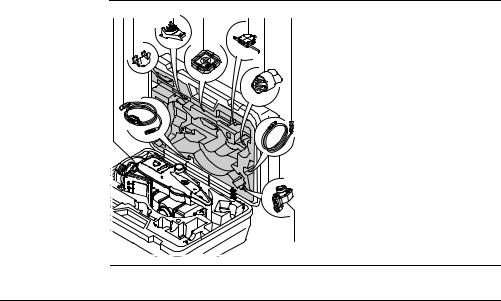
1.2
Содержимое контейнера — рис. 1
Содержимое контейнера
|
a b c |
d |
e |
f g |
h |
|
a) |
Инструмент с трегером |
||
|
b) |
Кабель GEV189 (USB-RS232)* |
||
|
c) |
Съемный круглый уровень GLI115* |
||
|
d) |
Гнездо GHT196 для измерителя |
||
|
высоты инструмента* |
|||
|
e) |
Плоский отражатель CPR105* |
||
|
f) |
Измеритель высоты инструмента |
||
|
GHM007* |
|||
|
g) |
Бленда и крышка для объектива* |
||
|
h) |
Кабель GEV223 (USB-mini USB) — для |
||
|
инструментов, где есть Крышка |
|||
|
коммуникационного блока |
|||
|
i) |
Мини-призма GMP111* |
||
|
TS0X_069a |
i |
* |
Опции |
|
Описание системы |
FlexLine, 15 |

|
Описание системы |
FlexLine, 16 |
Содержимое контейнера — рис. 2
|
j |
k |
|||
|
j) |
Юстировочные приспособления |
|||
|
k) |
Насадка GFZ3 на окуляр* |
|||
|
l) |
Аккумуляторы GEB211* |
|||
|
m) |
Зарядное устройство GKL211 |
|||
|
n) |
Адаптер GAD105 для плоских и |
|||
|
мини-призм* |
||||
|
o) |
USB-флэшка MS1 Leica для исполь- |
|||
|
зования с инструментами, в которых |
||||
|
имеется Крышка коммуникационно- |
||||
|
го блока |
||||
|
p) |
Аккумулятор GEB221 battery* |
|||
|
q) |
Наконечник для вешек мини-призм* |
|||
|
r) |
Противовес для использования |
|||
|
насадки на окуляр |
||||
|
s) |
Руководство по эксплуатации |
|||
|
t) |
Мини-вешка GLS115* |
|||
|
l |
m n o p q r |
s t |
* |
Опции |
|
TS0X_069b |
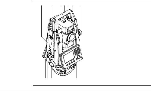
1.3
Компоненты
инструмента
Компоненты тахеометра
|
a |
b |
c d e f |
g |
|
|
a) |
Отсек для хранения USB-флэшки и |
|||
|
USB-кабеля* |
||||
|
b) |
Антенна Bluetooth* |
|||
|
c) |
Оптический визир |
|||
|
d) |
Съемная транспортировочная ручка |
|||
|
с установочным винтом |
||||
|
e) |
Лазерный маячок — EGL |
|||
|
f) |
Объектив со встроенным дальноме- |
|||
|
ром (EDM). Выход лазерного луча |
||||
|
g) |
Микрометренный винт вертикально- |
|||
|
го круга |
||||
|
h) |
Кнопка включения |
|||
|
i) |
Триггер |
|||
|
j) |
Микрометренный винт горизонталь- |
|||
|
ного круга |
||||
|
k) |
Вторая клавиатура* |
|||
|
TSOX_009a |
h i j |
k |
* |
Опции |
|
Описание системы |
FlexLine, 17 |

|
Описание системы |
FlexLine, 18 |
|
|
Компоненты |
l |
m |
|
инструмента |
||
|
(продолжение) |
|
l) |
Фокусировочное кольцо объектива |
|||
|
m) |
Фокусировочное кольцо окуляра |
|||
|
n) |
Крышка аккумуляторного отсека |
|||
|
o) |
Порт RS232 |
|||
|
p) |
Подъемный винт |
|||
|
q) |
Дисплей |
|||
|
TSOX_009b n o |
p q |
r |
r) |
Клавиатура |

Крышка коммуникационного блока
Крышка коммуникационного блока является опцией для 
 и установлен стандартно на
  .
.
|
a |
|||
|
b |
|||
|
c |
|||
|
a) |
Антенна Bluetooth |
||
|
d |
b) |
Крышка отсека |
|
|
c) Крепление для крышки USB-флеш- |
|||
|
ки |
|||
|
e |
d) |
Порт для USB-флешки |
|
|
e) |
USB-порт инструмента |
||
|
TSOX_130 |
|
Описание системы |
FlexLine, 19 |
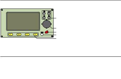
Пользовательский интерфейс |
FlexLine, 20 |
Пользовательский интерфейс
Клавиатура
|
Стандартная клавиатура |
Алфавитно-цифровая клавиатура |
||
|
a |
|||
|
a |
|||
|
f |
|||
|
b |
b |
||
|
c |
c |
||
|
d |
|||
|
e |
d |
||
|
TSOX_011 |
e |
||
|
TSOX_010 |
|||
|
a) |
Фикс. клавиши |
d) |
Кнопка ESC |
|
b) |
Навигатор |
e) |
Функциональные клавиши F1 — F4 |
|
c) |
Кнопка ENTER |
f) |
Алфавитно-цифровая панель |
Клавиша Описание
Служит для пролистывания страниц. С ее помощью можно переходить от одной страницы окна к другой.
Кнопка FNC. Обеспечивает быстрый доступ к операциям измерения.
![]()
Клавиша Описание
Пользовательская клавиша 1. Ей можно прописать нужную функцию в меню FNC menu.
Пользовательская клавиша 2. Ей можно прописать нужную функцию в меню FNC menu.
Навигатор. С его помощью можно перемещать полоску выбора в пределах окна focus bar и полоску ввода в конкретном поле меню.
Кнопка ENTER Служит для подтверждения операции ввода и перехода к следующему полю на дисплее.
Кнопка ESC Выход из текущего окна или режима редактирования без сохранения сделанных изменений. Переход к следующему более высокому уровню.
|
, |
, |
Клавиши, которым прописаны определенные функции. Они показаны |
|
, |
в нижней части экрана. |
Алфавитно-цифровая панель для ввода текстовых или цифровых данных.
|
Пользовательский интерфейс |
FlexLine, 21 |

|
Пользовательский интерфейс |
FlexLine, 22 |
Клавиши на корпусе тахеометра
2.2
Дисплей
Клавиша Описание
On/Off. Включение и выключение инструмента.
Триггер Эту клавишу можно запрограммировать для выполнения функций ALL (ВСЕ) или DIST (РАССТ).

 Можно прописать обе функции.
 Можно прописать одну из функций.
Запрограммировать триггерную клавишу можно в Меню настроек. Прочтите главу «4.1 Общие настройки».
Дисплей
a b c
|
d |
a) |
Название окна |
|||
|
b) Полоска выбора. Активное поле |
|||||
|
e |
c) |
Иконки статуса |
|||
|
d) |
Строки (поля) |
||||
|
S_TSOX_001 |
e) |
Дисплейные клавиши |
|||
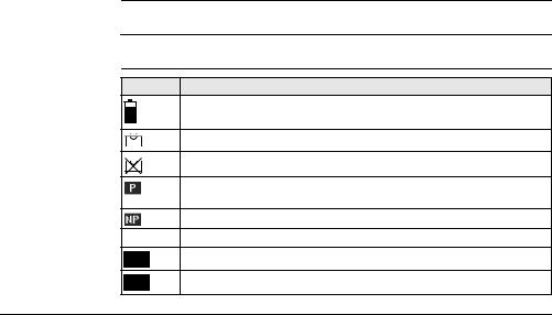
Все показанные здесь и далее окна служат только примерами. В зависимости от установленного системного ПО их вид может быть несколько иным.
2.3Иконки статуса
Эти иконки отражают текущий статус основных функций тахеометра. В зависимости от версии системного ПО их состав может быть различным.
Иконка Описание
Пиктограмма батарейки показывает уровень зарядки аккумулятора, в приведенном примере: 75%.
Компенсатор включен.
Компенсатор выключен.
В режиме EDM с отражателем измерения производятся на призмы или на объекты с высокой отражательной способностью.
Безотражательный режим для измерений на любые объекты.
!Режим сдвига активен.
|
012 |
Панель находится в цифровом режиме. |
|
ABC |
Панель находится в алфавитно-цифровом режиме. |
|
Пользовательский интерфейс |
FlexLine, 23 |
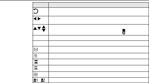
|
Пользовательский интерфейс |
FlexLine, 24 |
|
Иконка |
Описание |
|
Индикация настройки измерения горизонтальных углов против |
|
|
часовой стрелки. |
|
|
Этот символ указывает, что с данным полем связан список для |
|
|
выбора. |
|
|
Стрелки вверх и вниз показывают, в данном окне имеется несколько |
|
|
страниц которые можно просматривать с помощью . |
|
|
Положение I вертикального круга (например, КЛ). |
|
|
Положение II вертикального круга (например, КП). |
|
|
Выбрана стандартная призма Leica. |
|
|
Выбрана мини-призма Leica. |
|
|
Выбрана призма Leica 360°. |
|
|
Выбрана мини-призма Leica 360°. |
|
|
Выбрана отражающая полоска Leica. |
|
|
Выбран пользовательский тип отражателя. |

Иконка Описание
Bluetooth-устройство подключено. Если рядом с этой иконкой стоит крестик, это значит, что для связи выбран коммуникационный порт Bluetooth, но он пока неактивен.
Выбран коммуникационный порт USB.
2.4Дисплейные клавиши
|
Описание |
Дисплейные клавиши выбираются нажатием на соответствующие кнопки F1 — F4. |
||
|
Далее описаны фунции, которые можно прописать обычным дисплейным |
|||
|
клавишам. Возможности использования специальных дисплейных клавиш |
|||
|
описаны в соответствующих разделах, посвященных прикладным программам. |
|||
|
Обычные функции |
|||
|
Клавиша |
Описание |
||
|
дисплейных |
|||
|
-> ABC |
Переключение панели в алфавитно-цифровой режим. |
||
|
клавиш |
|||
|
-> 012 |
Переключение панели в цифровой режим. |
||
|
ВСЕ |
Запуск угловых и линейных измерений с сохранением результатов. |
||
|
РАССТ |
Запуск угловых и линейных измерений без записи результатов. |
||
|
EDM |
Просмотр и изменение настроек дальномера EDM. Прочтите главу |
||
|
«4.2 Настройка дальномера EDM». |
|||
|
YXH |
Открытие окна ручного ввода координат. |
||
|
Пользовательский интерфейс |
FlexLine, 25 |

|
Пользовательский интерфейс |
FlexLine, 26 |
|||
|
Клавиша |
Описание |
|||
|
ВЫХОД |
Выход из текущего окна или приложения. |
|||
|
ПОИСК |
Поиск заданной точки. |
|||
|
ВВОД |
Активизация алфавитно-цифровых дисплейных клавиш для |
|||
|
ввода тестовой информации. |
||||
|
P/NP |
Переключение между измерением на отражатели и безотражатель- |
|||
|
ным режимом. |
||||
|
СПИСОК |
Вывод на диспоей списка всех доступных точек. |
|||
|
OK |
В полях и окошках ввода: Подтверждение результатов измерений |
|||
|
или введенных значений и продолжение работы. |
||||
|
В окошке сообщений: Подтверждение получения сообщения и |
||||
|
продолжение текущих операций, либо возврат в предыдущее окно |
||||
|
для внесения изменений. |
||||
|
ПРЕДЩ |
Возврат в предыдущее активное окно. |
|||
|
ЗАП |
Запись выведенных на дисплей значений. |
|||
|
RESET |
Переустановка всех полей редактирования на значения по умолчанию. |
ПРОСМОТ Вывод на дисплей координат и сведений о проекте.
Переход к следующему уровню дисплейных клавиш.
Возврат к первому уровню дисплейных клавиш.

2.5Принципы работы
|
Включение и |
Для этой цели предназначена кнопка, находящаяся на боковой стойке тахеометра. |
|
выключение |
|
|
инструмента |
|
|
Выбор языка |
|
|
После включения инструмента можно выбрать удобный для пользователя язык |
|
|
интерфейса. Диалоговое окно для выбора языка будет выводиться на дисплей |
|
|
только в тех случаях, когда в тахеометр загружены два языка, и если в окне |
|
|
Настройки установлено Выбор языка: Вкл. Прочтите главу «4.1 Общие настройки». |
|
|
Алфавитно- |
|
|
Эта часть клавиатуры служит для ввода символов в поля редактирования. |
|
|
цифровая панель |
• Цифровые поля: Они могут содержать только численные величины. При |
|
нажатии на кнопку этой панели на дисплее появится соответствующая цифра. |
|
|
• Алфавитно-цифровые поля: Они могут содержать как числа, так и буквы. |
|
|
При нажатии на кнопку этой панели на дисплее появится первый символ, |
|
|
указанный над нажатой кнопкой. Повторные нажатия на ту же кнопку |
|
|
приводят к появлению других закрепленной за ней символов. |
|
|
Например: 1->S->T->U->1->S…. |
|
|
Стандартная |
Для ввода символов как с обычной клавиатуры выберите опцию ВВОД, и дисплей- |
|
клавиатура |
ные клавиши будут работать для ввода алфавитно-цифровых значений в режиме |
|
редактирования. Нажмите на соответствующую кнопку для ввода нужного символа. |
|
|
Пользовательский интерфейс |
FlexLine, 27 |

|
Пользовательский интерфейс |
FlexLine, 28 |
|
|
Поля |
|
ESC Служит для удаления символов из поля с восстановлением |
|
редактирования |
предыдущего значения. |
Перемещение курсора влево. Перемещение курсора вправо.
Вставка символа в текущее положение курсора. Удаление символа из текущей позиции курсора.
В режиме редактирования положение десятичной точки изменить нельзя. Эта позиция при вводе пропускается.
|
Специальные |
Символ |
Описание |
||
|
символы |
||||
|
* |
Используется как заместитель любого символа в полях поиска точек |
|||
|
или кодов. Прочтите главу «2.6 Поиск точек». |
||||
|
+/- |
В полях редактирования знаки «+» и «-» трактуются как обычные |
|||
|
символы, а не как знаки математических операций. |
||||
|
|
«+» / «-» могут появляться только в первой позиции поля. |
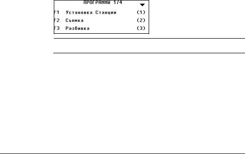
В данном примере нажатие на кнопку 3 на алфавитно-цифровой клавиатуре приводит к запуску приложения Разбивка.
2.6Поиск точек
|
Общие сведения |
Поиск точки (Pointsearch) является функцией, которая используется в различных |
|
приложениях для быстрого поиска нужных измеренных или твердых точек в |
|
|
памяти. |
|
|
Можно ограничить диапазон поиска пределами конкретного прокекта, либо искать |
|
|
точку по всем записям в памяти. Прежде всего, по заданному критерию ищутся |
|
|
твердые точки, а потом уже измеренные. Если найдено несколько точек, отвечаю- |
|
|
щих заданному критерию поиска, то их список будет упорядочен по дате их |
|
|
последнего ввода или редактирования. Прежде всего, ищутся наиболее «свежие» |
|
|
твердые точки. |
|
|
Прямой поиск |
При задании конкретного номера точки, например 402, после нажатия на ПОИСК |
|
все точки данного проекта с таким номером будут найдены и выведены на |
|
|
дисплей. |
|
Пользовательский интерфейс |
FlexLine, 29 |

|
Пользовательский интерфейс |
FlexLine, 30 |
|
ПОИСК |
|||
|
Поиск точек по заданному шаблону |
|||
|
в пределах выбранного проекта. |
|||
|
XYH=0 |
|||
|
Установка координат точки на нуле- |
|||
|
вые значения. |
|||
|
Поиск по |
|||
|
Поиск по шаблону имени проводится с применением символа «*». Эта звездочка |
|||
|
шаблонам |
может замещать любой символ на любой позиции в разыскиваемом имени. Такая |
||
|
(Wildcard search) |
возможность очень полезна в тех случаях, когда полное имя точки неизвестно или |
||
|
забыто, либо при пакетном поиске точек. |
|||
|
Примеры поиска |
|||
|
* |
Будут найдены все имеющиеся в проекте точки. |
||
|
точек |
A |
Будут найдены все точки с именем «A». |
|
|
A* |
Будут найдены все точки, имя которых начинается с «A», например, A9, |
||
|
A15, ABCD, A2A. |
|||
|
*1 |
Будут найдены все точки, содержащие в своем имени «1», например, 1, A1, |
||
|
AB1. |
|||
|
A*1 |
Будут найдены все, имя которых начинается с «A» и содержит «1» на любой |
||
|
позиции, напрмер, A1, AB1, A51. |
|||
![]()
3.1Установка тахеометра
Общие сведения В этом разделе описаны процедуры установки тахеометра над маркированной точкой с использованием лазерного отвеса. Естественно, тахеометр можно устанавливать и на произвольных точках.
Важные рекомендации:
•Настоятельно рекомендуется защищать прибор от прямых солнечных лучей и стараться избегать ситуаций с резкими перепадами температур вблизи него.
•Лазерный отвес, рассматриваемый в данном разделе, встроен в ось вращения тахеометра. Он проецирует на землю пятно красного цвета, что значительно облегчает процедуру центрирования.
•Лазерный отвес не может использоваться на трегерах, имеющих оптический отвес.
|
Основные действия |
FlexLine, 31 |

|
Основные действия |
FlexLine, 32 |
|
|
Штатив |
|
При установке инструмента старайтесь |
|
обеспечивать близкое к горизонтально- |
||
|
му положение головки штатива. |
||
|
Небольшие коррекции при этом могут |
||
|
быть сделаны с помощью подъемных |
||
|
винтов подставки. Если наклон слиш- |
||
|
TSOX_012b |
ком велик, то изменяйте соответствую- |
|
|
щим образом выдвижение ножек |
||
|
штатива. |
TSOX_012a
|
a |
Слегка отпустите винты фиксации длины |
|
ножек штатива, и выдвиньте ножки на |
|
|
нужную длину и затяните винты. |
|
|
a Проверьте, чтобы ножки штатива |
|
|
были надежно заглублены в землю. |
|
|
b |
b Прикладывать усилие к ножкам |
|
штатива нужно вдоль их длины. |

|
Уход за штативом. |
||
|
• Проверяйте надежность всех винтов и |
||
|
болтов штатива. |
||
|
• |
При транспортировке обязательно |
|
|
используйте чехол. |
||
|
• Используйте штатив только по его |
||
|
TSOX_012c |
штатному назначению. |
|
|
2 |
7 |
|
|
3 |
||
|
6 |
||
|
1 |
5 |
5 |
|
1 |
4 |
|
|
1 |
5 |
|
|
TSOX_013 |
1.Выдвиньте ножки штатива на удобную для вас длину. Установите штатив в более-менее центрированное положение над твердой точкой.
2.Установите на штатив тахеометр с трегером в надежном положении.
3.Включите инструмент. Если в его настройках задана коррекция наклона по одной или двум осям, то лазерный отвес включится автоматически, а на дисплее появится окно Уровень/Отвес. В других ситуациях нажмите на
|
Основные действия |
FlexLine, 33 |

|
Основные действия |
FlexLine, 34 |
Горизонтирование с помощью электронного уровня
кнопку FNC из того приложения, которое на данный момент активно и выберите Уровень/Отвес.
4.Изменяя положение ножек штатива (1) и вращая подъемные винты (6), наведите пятно лазерного отвеса (4) на точку на земле.
5.Работая ножками штатива (5), приведите в нульпункт круглый уровень (7).
6.Вращением подъемных винтов (6), точно отгоризонтируйте тахеометр по электронному уровню (7). Обратитесь к разделу «Горизонтирование с помощью электронного уровня».
7.Точно отцентрируйте тахеометр над точкой, передвигая трегер по головке штатива (2).
8.Повторяйте шаги 6. и 7. до достижения точного центрирования и нивелирования тахеометра.
Электронный уровень предназначен для точного горизонтирования тахеометра с помощью подъемных винтов подставки.
1.Поверните инструмент так, чтобы ось вращения трубы была параллельна двум подъемным винтам.
2.Приведите в нульпункт круглый уровень с помощью подъемных винтов.
3.Включите инструмент. Если в его настройках задана коррекция наклона по одной или двум осям, то лазерный отвес включится автоматически, а на дисплее появится окно Уровень/Отвес. В других ситуациях нажмите на кнопку FNC из того приложения, которое на данный момент активно и выберите Уровень/Отвес.
«Пузырек» электронного уровня и стрелки, указывающие нужное направление вращения подъемных винтов появятся на дисплее, если наклоны инструмента находятся в допустимых пределах.

4.Приведите электронный уровень в нульпункт по первой оси, вращая два подъемных винта. Стрелки подсказывают направление для вращения подъемных винтов. Когда электронный уровень будет приведен в нульпункт, эти стрелки будут заменены маркерами.
5.Приведите электронный уровень в нульпункт по всторой оси, вращая третий подъемный винт. Стрелка подскажет нужное направление его вращения. Когда электронный уровень будет приведен в нульпункт, стрелка будет заменена маркером.
Появление трех маркеров на дисплее означает, что инструмент точно отгоризонтирован.
6.Нажмит на OK.
|
Основные действия |
FlexLine, 35 |

|
Основные действия |
FlexLine, 36 |
Изменение яркости луча лазерного отвеса
Уровень освещенности на месте работ и тип поверхности на точке установки инструмента могут потребовать регулировки яркости лазерного луча отвеса.
TSOX_092
В окне Уровень/Отвес можно менять яркость луча лазерного отвеса. Изменение его яркости производится шагами по 25%.
Центрированиенад вертикальными трубами и колодцами
В некоторых случаях лазерное пятно отвеса не может быть видимым, например, при центрировании тахеометра над вертикальными трубами. В этой ситуации можно использовать прозрачную пластину для проектирования на нее луча лазерного отвеса и приведения его направления на геометрический центр трубы или колодца.
TSOX_014

3.2Эксплуатация аккумулятора
Первая зарядка аккумулятора
•Аккумуляторные батареи следует полностью зарядить до их первого использования в работе, поскольку они поставляются при минимальном уровне зарядки.
•Новые или долго (более трех месяцев) хранившиеся без подзарядки аккумуляторы следут пропустить через однократный цикл полной разрядки и зарядки.
•Этот цикл следует проводить при температуре от 0°до +40°C. Рекомендуемая оптимальная температура зарядки: +10°C +20°C.
•Нагрев батарей во время их зарядки является нормальным эффектом. Leica GeosystemsПри использовании зарядных устройств, рекомендуемых Leica Geosystems, слишком высокий нагрев аккумулятора приведет к автоматической остановке процесса зарядки.
Разрядка аккумуляторов
•Аккумуляторы могут использоваться при температурах от -20° до +50°C.
•Слишком низкие температуры снижают емкость аккумуляторов, а слишком высокие — срок их службы.
•Для литий-ионных (Li-Ion) аккумуляторов рекомендуется проводить цикл полной разрядки и зарядки, если на индикаторе зарядного устройства или самой батарейке фирмы Leica Geosystems отмечается сильное отличие от номинальной емкости.
|
Основные действия |
FlexLine, 37 |

|
Основные действия |
FlexLine, 38 |
||
|
Замена |
|||
|
аккумулятора |
|||
|
1 |
3 |
||
|
Откройте батарейный отсек (1) достань- |
|||
|
те оттуда кассету с батарейкой (2). |
|||
|
2 |
Вытащите батарейку из кассеты (3). |
||
|
TSOX_015 |
TSOX_016
|
4 |
Вставьте другую батарейку в кассету (4) |
|
|
так, чтобы контакты были обращены |
||
|
вверх. Батарейка должна вставляться |
||
|
до щелчка. |
||
|
6 |
5 |
Вставьте кассету в батарейный отсек (5) и |
|
поверните ручку для его закрытия (6). |
||
Полярность аккумулятора указана внутри кассеты.

3.3Хранение данных
Общие сведения На всех тахеометрах этой серии установлена внутренняя память. Встроенное программное обеспечение FlexField хранит все данные проектов в базе данных этой памяти. Оттуда данные могут экспортироваться на компьютер или другое устройство для постобработки через кабель LEMO cable, подключенный к порту RS232.
Для тахеометров, на которых имеется Крышка коммуникационного блока, данные из памяти могут экспортироваться с помощью:
•Флэш-карты, вставляемой в порт USB,
•Кабеля USB, подключаемого к USB-порту инструмента
•Bluetooth-соединения.
Обратитесь к главе «10 Управление данными» для получения более подробной информации об передаче данных и об управлении ими.
3.4Главное меню
|
Описание |
ГЛАВНОЕ МЕНЮ является стартовым окном для доступа к функциональным |
|
возможностям инструмента. Оно обычно открывается сразу после включения |
|
|
тахеометра или после окна Уровень/Отвес. |
При необходимости можно сконфигурировать тахеометр так, что после окна Уровень/Отвес открывалось не ГЛАВНОЕ МЕНЮ, а какое-либо другое окно. Прочтите главу «5.2 Порядок действий при включении».
|
Основные действия |
FlexLine, 39 |

|
Основные действия |
FlexLine, 40 |
ГЛАВНОЕ МЕНЮ
Описание функций Главного меню
|
Функция |
Описание |
|
Q-Съемка |
Программа УСК.СЪЕМКА позволяет сразу приступить к работе. |
|
Прочтите главу «3.5 Приложение Ускоренная съемка (Q-Survey)». |
|
|
Прогр. |
Выбор и запуск нужного приложения. Прочтите главу «9 Приложе- |
|
ния». |
|
|
Управл. |
Управление проектами, данными, списками кодов, форматами и |
|
файлами в системной памяти или на флэш-карте. Прочтите главу |
|
|
«10 Управление данными». |
|
|
Данные |
Экспорт и импорт данных. Прочтите главу «10.2 Экспорт данных». |
|
Настр. |
Изменение настроек дальномера EDM, коммуникационных парамет- |
|
ров и общих настроек тахеометра. Прочтите главу «4 Настройка». |
|
![]()
Функция Описание
Инструм Доступ к средствам поверки и калибровки тахеометра, настройки порядка его включения, изменения PIN-кода, лицензионного ключа
исистемных сообщений. Прочтите главу «5 Инструментарий».
3.5Приложение Ускоренная съемка (Q-Survey)
|
Описание |
После установки и включения тахеометра можно сразу приступать к работе. |
|
|
Доступ |
Откройте меню Q—съемка из окна ГЛАВНОЕ МЕНЮ. |
|
|
УСКОРЕННАЯ |
КОД |
|
|
СЪЕМКА |
Поиск или ввод кодов. Прочтите |
|
|
главу «7.1 Стандартное кодирова- |
||
|
ние». |
||
|
СТАНЦИЯ |
||
|
Ввод данных о точке установки |
||
|
инструмента и подготовка его к |
||
|
работе. |
||
|
Hz=0 |
||
|
Ориентирование горизонтального |
||
|
круга на 0. |
|
Основные действия |
FlexLine, 41 |

|
Основные действия |
FlexLine, 42 |
 Hz
Hz  / Hz
/ Hz 
Задание отсчетов горизонтальных углов против часовой стрелки или по часовой стрелке.
Работа с Q-съемка вполне аналогична работе с программой Съемка. По этой причине операции в этом режиме описаны лишь однажды, в главе, посвященной прикладным программам. Прочтите главу «9.3 Съемка».
3.6Измерения расстояний — рекомендации по получению надежных результатов
|
Описание |
Лазерный дальномер (EDM) установлен на всех приборах серии FlexLine |
|
|
instruments. Во всех прибрах этой серии расстояния измеряются с помощью |
||
|
лазерного луча видимого красного диапазона, который выходит по оптической оси |
||
|
из центра объектива. Есть два режим EDM: |
||
|
• Измерения на отражатели |
• Безотражательные измерения |
|

Безотражательные измерения
TSOX_093
• При запуске дальномерных измерений EDM определяет расстояние до объекта, который в данный момент находится на пути лазерного луча. При возникновении препятствий на пути расспространения луча к объекту, например, проезжающая машина сильный дождь, туман или снег, инструмент может измерить расстояние до такой помехи, а не до нужного объекта.
|
• Следите за тем, чтобы лазерный луч не попадал на объекты вблизи пути его |
|
|
распространения, например, на сильно отражающие поверхности. |
|
|
• Это особенно важно в безотражательном режиме и при измерениях на |
|
|
отражающие полоски. |
|
|
• Не наводите одновременно два инструмента на один и тот же объект. |
|
|
Измерения на |
|
|
• Точные измерения на отражатели должны выполняться на стандартную |
|
|
отражатели |
призму. |
|
• Не выполняйте безотражательные измерения на сильно отражающие |
|
|
объекты, такие как, например дорожные знаки. Такие измерения могут быть |
|
|
очень неточными. |
|
Основные действия |
FlexLine, 43 |

|
Основные действия |
FlexLine, 44 |
•При запуске дальномерных измерений EDM определяет расстояние до объекта, который в данный момент находится на пути лазерного луча. Если на пути распространения лазерного луча встречаются автомобили, люди, животные или свисающие ветки деревьев, часть принимаемого сигнала будет отражена именно от них, что способно привести к неверным результатам.
•При измерениях на отражатели такие помехи могут оказать влияние на точность результатов только на расстоянии до 30 метров от инструмента при длине определяемого расстояния свыше 300 м.
•Поскольку сам процесс дальномерных измерений занимает очень мало времени, всегда есть возможность поймать момент, когда помех на пути распространения луча не будет.
Предупрежде- По технике безопасности работы с лазером, допускается использовать дальномер ние только для измерений на отражатели на расстояния свыше 1000 м.
|
Красный лазер и |
• Наблюдения на отражатель в режиме >3.5 km позволяют измерять расстояния |
|
отражатели |
длиной более 3.5 км на стандартные отражатели с помощью лазерного луча |
|
видимого красного диапазона. |
|
|
Красный лазер и |
|
|
• Лазер видимого красного диапазона можно также использоваться для |
|
|
отражающие |
измерений на отражающие полоски. В таких случаях нужно обеспечить |
|
полоски |
попадание луча по перпендикуляру на отражающую полоску, которая должна |
|
быть хорошо закреплена на объекте. |
|
|
• Обязательно проверяйте соответствие заданного значения постоянного |
|
|
слагаемого параметрам используемого отражателя. |
|

4 Настройка
4.1Общие настройки
|
Доступ |
1. |
Откройте меню Установ. из окна ГЛАВНОЕ МЕНЮ. |
||||
|
2. |
Выберите Настр. в МЕНЮ НАСТРОЕК. |
|||||
|
3. |
Нажимайте на |
для пролистывания страниц доступных настроек. |
||||
Настройки
Уд.язык
Удаление выбранного языка.
Поле Описание
Контраст От 0% до 100% Установка контрастности дисплея шагами по 10%.
Триггер 1 / 1-й триггер — это верхняя часть триггерной клавиши, а 2-й триггер Трриггер 2 — нижняя часть этой клавиши.

|
Настройка |
FlexLine, 46 |
||||
|
Поле |
Описание |
||||
|
Выкл |
Триггер отключен. |
||||
|
ВСЕ |
Придает тригеру функции кнопки ALL (ВСЕ). |
||||
|
РАССТ |
Придает тригеру функции кнопки DIST (РАССТ). |
||||
|
Кнопка USER |
Конфигурирование |
или функциями из меню FNC. Прочтите |
|||
|
1 / 2 |
главу «6 Функции». |
||||
|
Корр.Наклона |
Выкл |
Компенсирование наклона отключено. |
|||
|
По 1-ой |
Вертикальные углы будут приводиться к |
||||
|
положению отвесной линии. |
|||||
|
По 2-м |
Вертикальные углы будут приводиться к |
||||
|
положению отвесной линии, горизонтальные углы |
|||||
|
исправляться за наклон оси вращения инструмента. |
|||||
|
Для правильного учета поправок, связанных с |
|||||
|
выбором в строке Поправка в гз.угол: ознакомь- |
|||||
|
тесь с таблицей «Поправки за наклон осей |
|||||
|
инструмента». |
При установке инструмента на нестабильной площадке, например на палубе корабля, компенсатор необходимо отключить. Это нужно для того, чтобы компенсатор не выходил за свой рабочий диапазон и не выдавал постоянно предупреждения о недопустимых наклонах инструмента.

|
Поле |
Описание |
|
|
Поправка в |
Вкл |
Активизация корректирования горизонтальных |
|
гз.угол |
углов. Для штатной работы при ориентировании |
|
|
прибора эта опция должна быть включена. Все |
||
|
измеренные горизонтальные углы будут скоррек- |
||
|
тированы с учетом вертикального угла соответс- |
||
|
твующих направлений. |
||
|
Для правильного учета поправок, связанных с |
||
|
выбором в строке Поправка в гз.угол: ознакомь- |
||
|
тесь с таблицей «Поправки за наклон осей |
||
|
инструмента». |
||
|
Выкл |
Отключение коррекции горизонтальных углов. |
|
|
Бип |
Это акустический сигнал, который выдается при нажатии на |
|
|
кнопки. |
||
|
Норм. |
Нормальная громкость. |
|
|
Громкий |
Повышенная громкость. |
|
|
Выкл |
Бип отключен. |
|

|
Настройка |
FlexLine, 48 |
||||
|
Поле |
Описание |
||||
|
Секторный |
Вкл |
Этот звуковой сигнал раздается при отсчетах по |
|||
|
бип |
горизонтальному кругу в 0°, 90°, 180°, 270° или 0, |
||||
|
100, 200, 300 град. |
|||||
|
90° |
1.Без бипов. |
||||
|
1 |
2.Бип в секторах |
||||
|
3 |
3 |
95.0 — 99.5 град и |
|||
|
105.0 — 100.5 град. |
|||||
|
2 |
2 |
3.Бип в секторах |
|||
|
99.5 — 99.995 град и |
|||||
|
100.5 — 100.005 |
|||||
|
1 |
град. |
||||
|
1 |
|||||
|
0° |
180° |
||||
|
TSOX_094 |
|||||
|
Выкл |
Секторный бип отключен. |
||||
|
Шаг по ГК |
вправо |
Отсчет горизонтальных углов по часовой стрелке. |
|||
|
влево |
Отсчет горизонтальных углов против часовой |
||||
|
стрелки. На дисплее отсчеты индицируются как |
|||||
|
выполненные против часовой стрелки, но |
|||||
|
записываются как сделанные по часовой |
|||||
|
стрелке. |
|||||

Поле Описание
Настройка Система отсчета вертикальных углов.
ВК
Зенит
0°
 45°
45°
90°
Зенитное расстояние=0°; Вертикальный угол=90°.
270°
TSOX_018
Гориз.
180°
TSOX_019
|
180° |
|
|
+90° |
+45° |
|
0° |
|
|
-45° |
|
|
-90° |
Зенитное расстояние=90°; Вертикальный угол=0°. Вертикальные углы считаются положительными при положении объекта над горизонтом инструмента и отрицательными — при его положении ниже этого горизонта.

|
Настройка |
FlexLine, 50 |
|||||||
|
Поле |
Описание |
|||||||
|
Уклон (%) |
Slope % |
45°=100%; Горизонт.=0°. |
||||||
|
+300 % |
Вертикальные углы |
|||||||
|
—.—% |
71°34” |
+100% |
||||||
|
выражаются в процентах |
||||||||
|
45° |
+18 % |
|||||||
|
20° |
уклона. Положительными |
|||||||
|
360s |
0° |
считаются уклоны вверх от |
||||||
|
— |
gon |
|||||||
|
±V |
горизонтальной плоскости, а |
|||||||
|
— |
50 |
|||||||
|
79,5 |
gon |
отрицательными — уклоны |
||||||
|
—.—% |
gon |
-100 % |
||||||
|
вниз от этой плоскости. |
||||||||
|
-300 % |
||||||||
|
|
||||||||
|
TSOX_020 |
Значения процента |
|||||||
|
уклона растут достаточно |
||||||||
|
быстро. Индикация —.—% |
||||||||
|
появляется на дисплее при |
||||||||
|
значениях уклона более |
||||||||
|
300%. |
|
Опред.Iкр.ле |
Задание положения вертикального круга относительно зритель- |
|
|
во |
ной трубы. |
|
|
Кр.лево |
При этом выборе «face I» будет считаться кругом |
|
|
лево. |
||
|
Кр.право |
При этом выборе «face I» будет считаться кругом |
|
|
право. |
 Loading…
Рекомендуем аналог
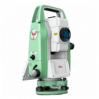
Описание
Комплектация
-
Стандартный комплект: тахеометр Leica FlexLine серии TS02 Power, трегер, Li-Ion аккумулятор, зарядное устройство, кабель передачи данных, ПО FlexOffice Standart, руководство пользователя, свидетельство о поверке, кейс, 2 наплечных ремня.
Файлы

Оформить заказ
Штатив для тахеометра В ПОДАРОК!!! По промокоду #Штатив в подарок# (Сообщите менеджеру при заказе) Уточняйте подробности 8-800-551-11-01
Экспертные мнения
Экспертные мнения
Радиостанции
Трегеры RGK
Рюкзаки и сумки RGK
Вехи RGK
Минипризмы RGK
Отражатель на веху
Трегеры GeoMax
Вехи SECO
Рюкзаки Vega
Аккумуляторные батареи
Рюкзаки и кейсы Geobond
Трегеры GEOBOND
Подставки для штативов
Переходники для штативов
Винты становые
Круговые отражатели
Чехлы для штативов
Штативы GeoBond
Окуляры для тахеометра
Призменные системы
Вехи GEOBOND
Минипризмы GEOBOND
Плёночные отражатели Geobond
Минипризмы Leica
Рулетки
Резьба станового винта — 5/8″;
Стандарт — WILD.
Подробнее
Резьба станового винта — 5/8″;
Стандарт — WILD;
Отвес — оптический (4Х).
Подробнее
- Резьба станового винта — 5/8″;
Подробнее
- Резьба станового винта — 5/8″;
- Стандарт -WILD;
- Отвес — оптический (4Х) .
Подробнее
- Резьба станового винта — 5/8″;
- Стандарт -WILD;
- Отвес — лазерный.
Подробнее
- Для тахеометров всех типов и аксессуаров;
Подробнее
- Назначение — для траиссоискателей Ridgid SR-20/24
- Габариты — 60*36*23 см
- Масса — 2,5 кг
Подробнее
- Назначение — для тахеометров
- Вес — 3,99 кг
Подробнее
- Высота — 2,5 м.
- Резьбовое соединение — 5/8»;
- Зажим — винт типа барашек;
Подробнее
- Высота — 2,5 м.
- Резьбовое соединение — 5/8»;
- Пузырьковый уровень;
- Зажим — вертикальная клипса;
Подробнее
- Высота — 3,6 м.
- Резьбовое соединение — 5/8»;
- Пузырьковый уровень;
- Зажим — винт типа барашек;
Подробнее
- Высота — 3,6 м.
- Резьбовое соединение — 5/8»;
- Пузырьковый уровень;
- Зажим — вертикальная клипса;
Подробнее
- Высота — 4,6 м.
- Резьбовое соединение — 5/8»;
- Пузырьковый уровень;
- Зажим — винт типа барашек;
Подробнее
- Высота — до 2,5 м;
- Масса — 1,09 кг;
- Тип зажима — винт;
- Материал — карбон.
Подробнее
- Высота — 5 м;
- Масса — 2,7 кг;
- Тип зажима — винт.
Подробнее
- Высота — 2.5 м;
- Масса — 0.93 кг;
- Резьбовое соединение — 5/8»;
- Тип — телескопическая;
- Количество секций — 2.
Подробнее
- Высота — 3.6 м;
- Масса — 1.29 кг;
- Резьбовое соединение — 5/8»;
- Тип — телескопическая;
- Количество секций — 3.
Подробнее
- Высота — 4.6 м;
- Масса — 1,99 кг;
- Резьбовое соединение — 5/8»;
- Тип — телескопическая;
- Количество секций — 4.
Подробнее
- Диаметр — 25 мм;
- Постоянная призмы (офсет) — 0 мм;
- Высота вехи — 1,3 м.
Подробнее
- Диаметр — 23 мм;;
- Высота вехи — 1,8 м.
- Вертикальное перемещение по вешке
Подробнее
Диаметр Ø=38 мм;
Постоянная призмы (офсет) К=0 мм;
Подробнее
- Диаметр — 35 мм.;
- Коэффициент — 30 мм. (0 мм.);
- Длина минивехи — 0.5-1.5 м;
- возможность вертикального перемещения по вешке
Подробнее
Постоянная призмы — 9 мм.
Подробнее
Постоянная призмы — 2 мм
Подробнее
- Винтовая резьба крепления — 5/8″;
- Диаметр призмы — Ø=64 мм;
- Константа = 0мм / -30мм.
Подробнее
- Винтовая резьба крепления — 5/8″;
- Константа =0мм / -30мм
- Подсветка отражателя
Подробнее
- Постоянная призмы — 30 мм / 0 мм;
- Диаметр призмы — 64 мм;
- Винтовая резьба крепления — 5/8″;
- Увеличенная марка
Подробнее
- Постоянная призмы — 30 мм / 0 мм;
- Диаметр призмы — 64 мм;
- Винтовая резьба крепления — 5/8″.
Подробнее
2,6 м, универсальная, TLV механизм (США)
Подробнее
фиберглассовая (вес 0,88 кг) , 2,6 м TLV механизм (США)
Подробнее
3.6м, универсальная (США)
Подробнее
фиберглассовая (вес 1,13 кг) , 3,6 м TLV механизм (США)
Подробнее
4.6м, универсальная (США)
Подробнее
для GNSS приемников
Подробнее
Материал: Алюминий
Подробнее
- Тип крепления:Резьба 5/8″
- Резьба в основании:5/8″
Подробнее
- Тип крепления:Leica
- Резьба в основании:5/8″
Подробнее
Резьба станового винта:5/8″
Подробнее
Отражатель круговой, призма круговая, призма 360
Подробнее
- Бренд:Geobond
- Коэффициент:23,1 мм
- Крепление на веху:Leica
Подробнее
- Бренд:Geobond
- Коэффициент:-30 мм (0 мм)
- Диаметр призмы:64 мм
- Крепление на веху:5/8″
Подробнее
- Бренд:Geobond
- Коэффициент:-30 мм (0 мм)
- Диаметр призмы:64 мм
- Крепление на веху:5/8″
Подробнее
- Длина: 130 см
- Материал: Нейлон
Подробнее
- Материал: Алюминий
- Рабочая высота: 1.55 м
Подробнее
- Материал:Алюминий
- Рабочая высота:1.6 м
- Длина в сложенном виде:1 м
Подробнее
- Материал:Алюминий
- Рабочая высота:1.55 м
Подробнее
Для тахеометров: Topcon GTS/GPT
Подробнее
Для тахеометров: Sokkia
Подробнее
Для тахеометров:Leica (кроме FlexLine и TS02 plus), GeoMax (кроме Zoom20 Pro, Zoom25, Zoom30 Pro)
Подробнее
Диаметр призмы:25 мм
Подробнее
Наконечник для вех Geobond серии ВК
Подробнее
Наконечник для вех Geobond серии SK
Подробнее
Съемный уровень для вех
Подробнее
- Материал: Карбон
- Рабочая высота: 2.5 м
Подробнее
- Материал:Алюминий
- Рабочая высота:2.5 м
Подробнее
- Материал:Алюминий
- Рабочая высота:3.6 м
- Длина в сложенном виде:1.5 м
Подробнее
- Материал:Алюминий
- Рабочая высота:5 м
- Длина в сложенном виде:1.6 м
Подробнее
- Бренд:Geobond
- Коэффициент:30 мм
- Диаметр призмы:22 мм
- Длина минивехи:0.3 — 1.25 м
Подробнее
- Бренд:Geobond
- Коэффициент:17.5 мм (0 мм)
- Диаметр призмы:25 мм
- Длина минивехи:0.3 — 1.25 м
Подробнее
- Бренд:Geobond
- Коэффициент:-30 мм (0 мм)
- Диаметр призмы:35 мм
- Длина минивехи:0.3 — 1.25 м
Подробнее
30 м / 13 мм / Сталь
Подробнее
Трегеры RGK
Резьба станового винта — 5/8″;
Стандарт — WILD.
Подробнее
Резьба станового винта — 5/8″;
Стандарт — WILD;
Отвес — оптический (4Х).
Подробнее
- Резьба станового винта — 5/8″;
Подробнее
- Резьба станового винта — 5/8″;
- Стандарт -WILD;
- Отвес — оптический (4Х) .
Подробнее
- Резьба станового винта — 5/8″;
- Стандарт -WILD;
- Отвес — лазерный.
Подробнее
Рюкзаки и сумки RGK
- Для тахеометров всех типов и аксессуаров;
Подробнее
- Назначение — для траиссоискателей Ridgid SR-20/24
- Габариты — 60*36*23 см
- Масса — 2,5 кг
Подробнее
- Назначение — для тахеометров
- Вес — 3,99 кг
Подробнее
Вехи RGK
- Высота — 2,5 м.
- Резьбовое соединение — 5/8»;
- Зажим — винт типа барашек;
Подробнее
- Высота — 2,5 м.
- Резьбовое соединение — 5/8»;
- Пузырьковый уровень;
- Зажим — вертикальная клипса;
Подробнее
- Высота — 3,6 м.
- Резьбовое соединение — 5/8»;
- Пузырьковый уровень;
- Зажим — винт типа барашек;
Подробнее
- Высота — 3,6 м.
- Резьбовое соединение — 5/8»;
- Пузырьковый уровень;
- Зажим — вертикальная клипса;
Подробнее
- Высота — 4,6 м.
- Резьбовое соединение — 5/8»;
- Пузырьковый уровень;
- Зажим — винт типа барашек;
Подробнее
- Высота — до 2,5 м;
- Масса — 1,09 кг;
- Тип зажима — винт;
- Материал — карбон.
Подробнее
- Высота — 5 м;
- Масса — 2,7 кг;
- Тип зажима — винт.
Подробнее
- Высота — 2.5 м;
- Масса — 0.93 кг;
- Резьбовое соединение — 5/8»;
- Тип — телескопическая;
- Количество секций — 2.
Подробнее
- Высота — 3.6 м;
- Масса — 1.29 кг;
- Резьбовое соединение — 5/8»;
- Тип — телескопическая;
- Количество секций — 3.
Подробнее
- Высота — 4.6 м;
- Масса — 1,99 кг;
- Резьбовое соединение — 5/8»;
- Тип — телескопическая;
- Количество секций — 4.
Подробнее
Минипризмы RGK
- Диаметр — 25 мм;
- Постоянная призмы (офсет) — 0 мм;
- Высота вехи — 1,3 м.
Подробнее
- Диаметр — 23 мм;;
- Высота вехи — 1,8 м.
- Вертикальное перемещение по вешке
Подробнее
Диаметр Ø=38 мм;
Постоянная призмы (офсет) К=0 мм;
Подробнее
- Диаметр — 35 мм.;
- Коэффициент — 30 мм. (0 мм.);
- Длина минивехи — 0.5-1.5 м;
- возможность вертикального перемещения по вешке
Подробнее
Постоянная призмы — 9 мм.
Подробнее
Постоянная призмы — 2 мм
Подробнее
Отражатель на веху
- Винтовая резьба крепления — 5/8″;
- Диаметр призмы — Ø=64 мм;
- Константа = 0мм / -30мм.
Подробнее
- Винтовая резьба крепления — 5/8″;
- Константа =0мм / -30мм
- Подсветка отражателя
Подробнее
- Постоянная призмы — 30 мм / 0 мм;
- Диаметр призмы — 64 мм;
- Винтовая резьба крепления — 5/8″;
- Увеличенная марка
Подробнее
- Постоянная призмы — 30 мм / 0 мм;
- Диаметр призмы — 64 мм;
- Винтовая резьба крепления — 5/8″.
Подробнее
Вехи SECO
2,6 м, универсальная, TLV механизм (США)
Подробнее
фиберглассовая (вес 0,88 кг) , 2,6 м TLV механизм (США)
Подробнее
3.6м, универсальная (США)
Подробнее
фиберглассовая (вес 1,13 кг) , 3,6 м TLV механизм (США)
Подробнее
4.6м, универсальная (США)
Подробнее
Рюкзаки и кейсы Geobond
для GNSS приемников
Подробнее
Подставки для штативов
Материал: Алюминий
Подробнее
Переходники для штативов
- Тип крепления:Резьба 5/8″
- Резьба в основании:5/8″
Подробнее
- Тип крепления:Leica
- Резьба в основании:5/8″
Подробнее
Винты становые
Резьба станового винта:5/8″
Подробнее
Круговые отражатели
Отражатель круговой, призма круговая, призма 360
Подробнее
- Бренд:Geobond
- Коэффициент:23,1 мм
- Крепление на веху:Leica
Подробнее
- Бренд:Geobond
- Коэффициент:-30 мм (0 мм)
- Диаметр призмы:64 мм
- Крепление на веху:5/8″
Подробнее
- Бренд:Geobond
- Коэффициент:-30 мм (0 мм)
- Диаметр призмы:64 мм
- Крепление на веху:5/8″
Подробнее
Чехлы для штативов
- Длина: 130 см
- Материал: Нейлон
Подробнее
Штативы GeoBond
- Материал: Алюминий
- Рабочая высота: 1.55 м
Подробнее
- Материал:Алюминий
- Рабочая высота:1.6 м
- Длина в сложенном виде:1 м
Подробнее
- Материал:Алюминий
- Рабочая высота:1.55 м
Подробнее
Окуляры для тахеометра
Для тахеометров: Topcon GTS/GPT
Подробнее
Для тахеометров: Sokkia
Подробнее
Для тахеометров:Leica (кроме FlexLine и TS02 plus), GeoMax (кроме Zoom20 Pro, Zoom25, Zoom30 Pro)
Подробнее
Призменные системы
Диаметр призмы:25 мм
Подробнее
Вехи GEOBOND
Наконечник для вех Geobond серии ВК
Подробнее
Наконечник для вех Geobond серии SK
Подробнее
Съемный уровень для вех
Подробнее
- Материал: Карбон
- Рабочая высота: 2.5 м
Подробнее
- Материал:Алюминий
- Рабочая высота:2.5 м
Подробнее
- Материал:Алюминий
- Рабочая высота:3.6 м
- Длина в сложенном виде:1.5 м
Подробнее
- Материал:Алюминий
- Рабочая высота:5 м
- Длина в сложенном виде:1.6 м
Подробнее
Минипризмы GEOBOND
- Бренд:Geobond
- Коэффициент:30 мм
- Диаметр призмы:22 мм
- Длина минивехи:0.3 — 1.25 м
Подробнее
- Бренд:Geobond
- Коэффициент:17.5 мм (0 мм)
- Диаметр призмы:25 мм
- Длина минивехи:0.3 — 1.25 м
Подробнее
- Бренд:Geobond
- Коэффициент:-30 мм (0 мм)
- Диаметр призмы:35 мм
- Длина минивехи:0.3 — 1.25 м
Подробнее
Плёночные отражатели Geobond
Рулетки
30 м / 13 мм / Сталь
Подробнее
Купить Тахеометр Leica TS02 power 3 в Тюмени легко — просто позвоните по телефону:: 8-800-551-11-01
Инструкция пользователя для тахеометра Leica FlexLine TS02/TS06/TS09
Инструкция пользователя для тахеометра Leica FlexLine TS02/TS06/TS09
версия 2.0

Данное руководство относится ко всем инструментам серии TS02/TS06/TS09. Отличия для конкретных моделей детально объясняются.
Инструмент для измерений, вычислений и записи данных. Отлично подходит как для обычных съемок, так и для решения более сложных задач. Оснащен встроенным программным обеспечением FlexField для решения широкого круга таких задач. Различные версии приборов этой серии имеют разную точность и свой набор функциональных возможностей. Все они могут подключаться для камеральной обработки к программе FlexOffice для просмотра данных, управления ими и обменов.
Обмен данными между инструментами серии FlexLine и компьютером осуществляется с помощью коммуникационного кабеля. Для инструментов, в которых имеется Крышка коммуникационно- го блока, возможен обмен данными и с помощью USB-флэшек, USB-кабелей или через Bluetooth.
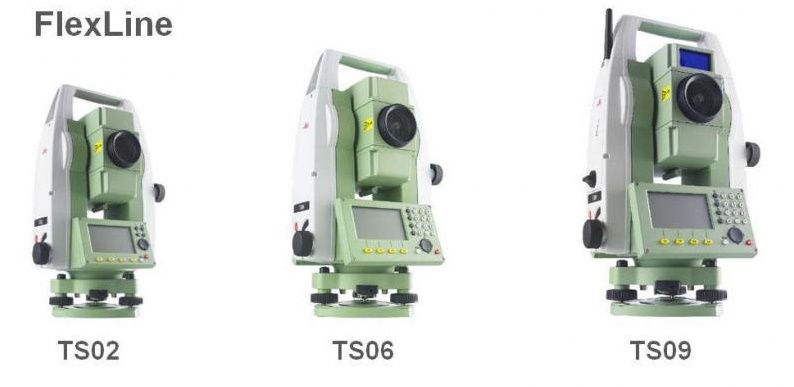
Остальное подробно в инструкции Leica FlexLine TS02/TS06/TS09