-
Contents
-
Table of Contents
-
Bookmarks
Quick Links
W211 Dual Battery System
W211 Dual Battery System
1
219 BCM (ACB-ICC) 11-29-02
Related Manuals for Mercedes-Benz W211
Summary of Contents for Mercedes-Benz W211
-
Page 1
W211 Dual Battery System W211 Dual Battery System 219 BCM (ACB-ICC) 11-29-02… -
Page 2
To help avoid personal injury to you or others, and to avoid damage to the vehicle on which you are working, you must always refer to the latest Mercedes-Benz Technical Publication and follow all pertinent instructions when testing, diagnosing or making repair. -
Page 3
Program Highlights Program Highlights • Power distribution — pre-fuse diagram — pre-fuse locations • Dual battery on-board electrical system components — systems battery — auxiliary battery — battery control module — auxiliary battery relay — cut-off relay for interruptible loads •… -
Page 4
W211 Dual Battery System Function W211 Dual Battery System Function An auxiliary battery supplies electrical energy for a limited time if the systems battery voltage is low. -
Page 5
Systems Battery (G1) Systems Battery (G1) Location: (G1) installed in trunk… -
Page 6
W211 Systems Battery (G1) W211 Systems Battery (G1) • Systems Battery: 12V, 95 Ah, 520A (DIN) • Absorbent Glass Mat (AGM) design, also known as Valve Regulated Lead Acid (VRLA) type • Function — Primary power source for all vehicle electrical systems… -
Page 7
Location of Auxiliary Battery (G1/7) Location of Auxiliary Battery (G1/7) Auxiliary battery installed below air intake of HVAC… -
Page 8
Location of Auxiliary Battery (G1/7) Location of Auxiliary Battery (G1/7) Shown with HVAC air intake / filter removed… -
Page 9
Auxiliary Battery (G1/7) Auxiliary Battery (G1/7) • Auxiliary Battery: 12V, 12Ah, 170 A (DIN) • Absorbent Glass Mat (AGM) design • Function — Provides supplemental power if systems battery (G1) voltage is low… -
Page 10
AGM / VRLA Battery Properties AGM / VRLA Battery Properties • Longer service life • Improved cold starting characteristics • Improved deep cycle performance • No liquid acid spills or leaks • Fast recharge time • Completely maintenance free… -
Page 11
AGM / VRLA Battery Testing • Requires the new Midtronics MCR 717 tester and printer • Tester measures battery conductance by inducing A/C voltage of a given frequency and amplitude on the battery posts and monitoring the current flow in response to it •… -
Page 12
Front Pre-fuse (F32) Front Pre-fuse (F32) 72 73 74 75 76 77 Location: Passenger footwell… -
Page 13
Pre-fuse Box (F33) Pre-fuse Box (F33) Location: Front of spare tire well… -
Page 14
Pre-fuse Power Distribution Pre-fuse Power Distribution N10/1 200 A Res. N10/2 200 A N10/1 40 A 150 A N10/11 40 A 150 A 40 A A7/3 40 A A7/3 50 A M4/7 N112 and A35/11 150 A X58/1 150 A M40/1 40 A Res. -
Page 15
Legend: Pre-fuse Block Power Distribution Legend: Pre-fuse Block Power Distribution A7/3 Traction system hydraulic unit A35/11 Voice recognition module (VCS) Front pre-fuse box Rear pre-fuse box Interior fuse box (left of instrument panel) Systems battery G1/7 Auxiliary battery Alternator K57/2 Auxiliary battery relay AIRmatic relay N10/1… -
Page 16
Battery Control Module (N82) Battery Control Module (N82) Location: Rear of spare tire well… -
Page 17
Function of N82 Function of N82 1. Monitors the voltages of (G1) and (G1/7) 2. Monitors alternator voltage (terminal 61) via CAN B 3. Controls auxiliary battery relay (K57/2) 4. Controls consumer prioritization function 5. Optimizes charging of auxiliary battery (G1/7) 6. -
Page 18
Auxiliary Battery Relay (K57/2) Auxiliary Battery Relay (K57/2) Location: Below windshield wiper cowl plastic trim Function: • Controlled by N82 • De-energized during normal operation (N.O.) • Energized to recharge G1/7 • Energized if engine running and system voltage low •… -
Page 19
Cut-off Relay for Interruptible Loads (K75) Cut-off Relay for Interruptible Loads (K75) Location: LF SAM (N10/1) Function: • Controlled by N82 • De-energized during normal operation (N.C.) • Energized during emergency operation • Opens 30/15R to cigar lighter (R3r1), and 12V socket (X58/1) rear of center console during emergency operation… -
Page 20
Normal Mode Normal Mode — Battery control module monitors Kl . 30 voltages and calculates the CAN-B condition of both batteries — Monitors total current Kl . 31 consumption through common ground G1/7 — Consumer prioritization off — Relay K57/2 de-energized K57/2 Battery K57/2… -
Page 21
Multi-Function Display Fault Messages Multi-Function Display Fault Messages… -
Page 22
Consumer Prioritization Consumer Prioritization If, for example, the alternator fails: • Both consumer prioritization stages (1 and 2) are immediately activated via the CAN • A red warning info appears in the instrument cluster • The auxiliary battery is not engaged until G1 voltage is low If, for example, N82 determines the load capacity of systems battery (G1) is inadequate: •… -
Page 23
Emergency Mode Emergency Mode Engine running, systems battery low: Kl . 30 CAN-B — Consumers deactivated in 2 stages by CAN messages Kl . 31 — Fault messages in instrument cluster indicate deactivation of G1/7 consumers — Auxiliary battery relay (K57/2) is energized. -
Page 24
Auxiliary Battery Charging Mode Auxiliary Battery Charging Mode — Battery control module detects Kl . 30 insufficient voltage at auxiliary CAN-B battery — Auxiliary battery relay (K57/2) is Kl . 31 activated for a short period of time if primary system voltage is G1/7 above 13.5V — Auxiliary battery is charged… -
Page 25
Dual Battery System Diagram CAN B Dual Battery System Diagram CAN B N10/1 — circuit 61 — ignition key inserted — diagnosis — systems battery sensing N10/2 — trunk switch G1/7 — auxiliary battery sensing — warning messages… -
Page 26
Dual Battery Service Tips Dual Battery Service Tips Normalization: If the systems battery is disconnected or dead, the following systems should be checked for normal operation. If systems are inoperative or erratic then normalization will have to be performed. Potential systems requiring normalizing are: •… -
Page 27
Appendix Appendix Topic WIS doc.# AH54.10-P-0002-01A Notes on AGM battery construction, and properties AR54.10-P-1129-01A Battery test using Midtronics MCR717 OF58.40-P-3000-04A Order form for Midtronics MCR717 GF54.10-P-4201T Auxiliary battery relay, location, and function GF54.10-P-1001T Two-battery vehicle power supply, function GF54.21-P-4121-02T Vehicle power supply control module, task ETM doc # PE54.15-P-2502DA Pre-fuse F32 wiring diagram…
Mercedes-Benz E-class

KeeperS
Был 5 дней назад
Я езжу на Subaru Forester Последний Самурай и Subaru Impreza Old School Car (до этого — Mercedes-Benz E-class)
Санкт-Петербург, Россия
Собственно ищу книжку . Покупать не хочу ибо не известно насколько долга будет наша дружба MB. Ищу в электроном виде
14 ноября 2014
Метки: плановое ТО
5
Далее Что поставить вместо шатного ГУ
Разместить рекламу
Реклама
Машины в продаже
Комментарии
5
Войдите или зарегистрируйтесь, чтобы писать комментарии, задавать вопросы и участвовать в обсуждении.
Войти
Зарегистрироваться

RouteMedia
Я езжу на Mercedes-Benz E-class (W211)
Тут есть инструкция
www.w202club.ru/g0501.html
5 лет

Vladimir00045
Я езжу на Nissan Serena Mk II (C24)
Норм нет. Раньше была ссылка на оф. сайте. Сейчас она не работает.
А зачем она, собственно? Вся инфа в том или ином виде есть в интернете.
8 лет

igrpravdin
Я езжу на Chevrolet Lanos
Нашел пока вот такое www.automnl.com/model/mb_e/
8 лет

techstieglitz
Я езжу на Mercedes-Benz E-class (W211)
Руководство по ремонту или инструкцию по эксплуатации? Если последнюю, то ссылок миллион в яндексе.
8 лет

KeeperS
Автор
Я езжу на Subaru Forester (SH)
Незнаю ничего не нашёл.
8 лет
Руководства по эксплуатации, обслуживанию и ремонту Mercedes-Benz E-класс
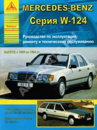
Мультимедийное руководство на немецком языке по техническому обслуживанию и ремонту автомобиля Mercedes-Benz серии W124 1985-1997 годов выпуска.
- Автор: —
- Издательство: Mercedes-Benz
- Год издания: —
- Страниц: —
- Формат: —
- Размер: 626,4 Mb
Мультимедийное руководство на английском языке по эксплуатации, техническому обслуживанию и ремонту автомобиля Mercedes-Benz серии W124 1985-1995 годов выпуска.
- Автор: —
- Издательство: —
- Год издания: —
- Страниц: —
- Формат: —
- Размер: 673,0 Mb
Руководство по эксплуатации и техническому обслуживанию и ремонту автомобиля Mercedes-Benz E-класса серии W124 с 1985 года выпуска.
- Автор: М.Е. Парфенов, М.А. Юдкевич
- Издательство: Машиностроение
- Год издания: 1993
- Страниц: 176
- Формат: PDF
- Размер: 72,0 Mb
Мультимедийное руководство по эксплуатации и ремонту автомобиля Mercedes-Benz серии W124 1985-1995 годов выпуска.
- Автор: —
- Издательство: —
- Год издания: —
- Страниц: —
- Формат: ISO
- Размер: 376,9 Mb
Мультимедийное руководство по эксплуатации и ремонту автомобиля Mercedes-Benz серии W124 1985-1995 годов выпуска.
- Автор: —
- Издательство: —
- Год издания: —
- Страниц: —
- Формат: —
- Размер: 185,5 Mb
Руководство по техническому обслуживанию и ремонту автомобиля Mercedes-Benz серии W124 1985-1993 годов выпуска с бензиновыми и дизельными двигателями.
- Автор: —
- Издательство: Ассоциация независимых издателей
- Год издания: 1998
- Страниц: 184
- Формат: PDF
- Размер: 65,3 Mb
Руководство по эксплуатации, техническому обслуживанию и ремонту автомобиля Mercedes-Benz серии W124 1985-1993 годов выпуска с бензиновыми и дизельными двигателями.
- Автор: —
- Издательство: Легион-Автодата
- Год издания: —
- Страниц: 460
- Формат: —
- Размер: —
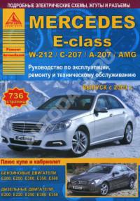
Руководство по эксплуатации и ремонту автомобиля Mercedes-Benz Е-класса серий W212/S212/L212/C207/A207 с 2009 года выпуска с бензиновыми и дизельными двигателями.
- Автор: —
- Издательство: Монолит
- Год издания: —
- Страниц: 618
- Формат: —
- Размер: —
Руководство по ремонту и эксплуатации Mercedes-Benz W124 1985-1995 г.
- Автор: —
- Издательство: ПЕТИТ
- Год издания: 2002
- Страниц: 290
- Формат: PDF
- Размер: 93,4 Mb
Руководство по эксплуатации и ремонту автомобилей Mercedes-Benz серии W124 (включая Е-класс) 1985-1995 годов выпуска с бензиновыми и дизельными двигателями.
- Автор: —
- Издательство: Гуси-Лебеди
- Год издания: —
- Страниц: 288
- Формат: —
- Размер: —
Руководство по техническому обслуживанию и ремонту автомобиля Mercedes-Benz Е-класса с 1995 года выпуска.
- Автор: Клаус Брейштедт
- Издательство: АСТ
- Год издания: 2006
- Страниц: 305
- Формат: PDF
- Размер: 183,3 Mb
Руководство по эксплуатации и техническому обслуживанию автомобиля Mercedes-Benz E-класса серии W124.
- Автор: —
- Издательство: Mercedes-Benz
- Год издания: 1993
- Страниц: 146
- Формат: JPG
- Размер: 15,6 Mb
Руководство по эксплуатации и техническому обслуживанию автомобиля Mercedes-Benz серии W210.
- Автор: —
- Издательство: Mercedes-Benz
- Год издания: —
- Страниц: —
- Формат: JPG
- Размер: 31,3 Mb
Руководство по эксплуатации и техническому обслуживанию автомобиля Mercedes-Benz серии W211.
- Автор: —
- Издательство: Mercedes-Benz
- Год издания: —
- Страниц: 328
- Формат: PDF
- Размер: 34,9 Mb
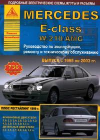
Руководство по эксплуатации, техническому обслуживанию и ремонту автомобиля Mercedes-Benz Е-класса серии W210 1995-2003 годов выпуска с бензиновыми и дизельными двигателями.
- Автор: —
- Издательство: Арго-Авто
- Год издания: —
- Страниц: 736
- Формат: —
- Размер: —
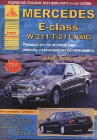
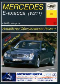
Руководство по эксплуатации, техническому обслуживанию и ремонту автомобиля Mercedes-Benz Е-класса серий W211/T211 2002-2009 годов выпуска с бензиновыми и дизельными двигателями.
- Автор: —
- Издательство: Арго-Авто
- Год издания: —
- Страниц: 704
- Формат: —
- Размер: —
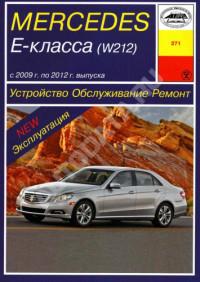
Руководство по эксплуатации, техническому обслуживанию и ремонту автомобиля Mercedes-Benz Е-класса серий W212/C207/A207 с 2009 года выпуска с бензиновыми и дизельными двигателями.
- Автор: —
- Издательство: Арго-Авто
- Год издания: —
- Страниц: 736
- Формат: —
- Размер: —
Руководство по эксплуатации, техническому обслуживанию и ремонту автомобиля Mercedes-Benz серии W124 1985-1994 годов выпуска с бензиновыми и дизельными двигателями.
- Автор: —
- Издательство: Арго-Авто
- Год издания: —
- Страниц: 304
- Формат: —
- Размер: —
Руководство по эксплуатации, техническому обслуживанию и ремонту автомобиля Mercedes-Benz Е-класса серии W212 2009-2012 годов выпуска.
- Автор: —
- Издательство: Арус
- Год издания: —
- Страниц: 398
- Формат: —
- Размер: —

Руководство по эксплуатации, техническому обслуживанию и ремонту автомобиля Mercedes-Benz Е-класса с 1995 года выпуска.
- Автор: —
- Издательство: Арус
- Год издания: —
- Страниц: 288
- Формат: —
- Размер: —
Руководство по эксплуатации, техническому обслуживанию и ремонту автомобиля Mercedes-Benz Е-класса серии W211 с 2002 года выпуска.
- Автор: —
- Издательство: Арус
- Год издания: —
- Страниц: 528
- Формат: —
- Размер: —
Руководство по эксплуатации, техническому обслуживанию и ремонту автомобиля Mercedes-Benz Е-класса серии W211 с 2002 года выпуска с дизельными двигателями.
- Автор: —
- Издательство: Арус
- Год издания: —
- Страниц: 492
- Формат: —
- Размер: —


At a glance
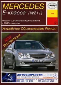
Cockpit
Left-hand-drive vehicles
|
16 |
Online Version (Edition F1, 06/03) |

|
Function |
Page |
||
|
1 |
Combination switch |
||
|
Main-beam head- |
49 |
||
|
lamps |
|||
|
Turn signals |
50 |
||
|
Windscreen wipers |
50 |
||
|
2 |
Cruise control lever |
||
|
Cruise control |
223 |
||
|
Distronic* |
227 |
||
|
Speedtronic |
237 |
||
|
SBC Stop* |
242 |
||
|
3 |
Instrument cluster |
22 |
|
|
4 |
Multi-function |
24 |
|
|
steering wheel |
|||
|
5 |
Horn |
||
|
Function |
Page |
|
|
6 |
Linguatronic lever* – |
|
|
see the separate |
||
|
Operating Instructions |
||
|
7 |
Parktronic* warning |
253 |
|
display |
||
|
8 |
Overhead control panel |
27 |
|
9 |
Opens the spectacles/ |
282 |
|
mobile phone compart- |
||
|
ment |
||
|
a |
Opens the glove com- |
282 |
|
partment |
||
|
b |
Glove compartment |
282 |
|
c |
Centre console |
25 |
|
d |
Ignition lock |
31 |
|
Function |
Page |
|
|
e |
Adjusts the steering |
38 |
|
wheel |
||
|
Switches the steering |
289 |
|
|
wheel heating* on/off |
||
|
f |
Opens the bonnet |
306 |
|
g |
Parking brake |
53 |
|
h |
Releases the parking |
47 |
|
brake |
||
|
j |
Door control panel |
28 |
|
k |
Light switch |
121 |
|
l |
Cleans the headlamps* |
175 |
|
Online Version (Edition F1, 06/03) |
17 |
At a glance
Cockpit
Right-hand-drive vehicles
|
18 |
Online Version (Edition F1, 06/03) |

|
Function |
Page |
||
|
1 |
Combination switch |
||
|
Main-beam head- |
49 |
||
|
lamps |
|||
|
Turn signals |
50 |
||
|
Windscreen wipers |
50 |
||
|
2 |
Cruise control lever |
||
|
Cruise control |
223 |
||
|
Distronic* |
227 |
||
|
Speedtronic |
237 |
||
|
SBC Stop* |
242 |
||
|
3 |
Instrument cluster |
20 |
|
|
4 |
Multi-function |
24 |
|
|
steering wheel |
|||
|
5 |
Horn |
||
|
Function |
Page |
|
|
6 |
Linguatronic lever* – |
|
|
see the separate |
||
|
Operating Instructions |
||
|
7 |
Parktronic* warning |
253 |
|
display |
||
|
8 |
Overhead control panel |
27 |
|
9 |
Opens the spectacles/ |
282 |
|
mobile phone compart- |
||
|
ment |
||
|
a |
Opens the glove com- |
282 |
|
partment |
||
|
b |
Glove compartment |
282 |
|
c |
Centre console |
25 |
|
d |
Ignition lock |
31 |
|
Function |
Page |
|
|
e |
Adjusts the steering |
38 |
|
wheel |
||
|
Switches the steering |
289 |
|
|
wheel heating* on/off |
||
|
f |
Opens the bonnet |
306 |
|
g |
Parking brake |
53 |
|
h |
Releases the parking |
47 |
|
brake |
||
|
j |
Door control panel |
28 |
|
k |
Light switch |
121 |
|
l |
Cleans the headlamps* |
175 |
|
Online Version (Edition F1, 06/03) |
19 |

At a glance
Instrument cluster
Kilometres
|
20 |
Online Version (Edition F1, 06/03) |

At a glance
Instrument cluster
|
Function |
Page |
||
|
1 |
Turn signal indicator |
50 |
|
|
lamp, left |
|||
|
2 |
ABS/ESP warning |
395 |
|
|
lamp |
|||
|
3 |
Speedometer |
129 |
|
|
4 |
Segments |
129 |
|
|
5 |
Multi-function |
130 |
|
|
display |
|||
|
Depending on setting |
|||
|
in the control system |
|||
|
Outside |
|||
|
temperature1 |
|||
|
Digital speedome- |
|||
|
ter |
|||
|
Status line |
|||
|
Trip meter |
|||
|
6 |
Distance warning |
227 |
|
|
lamp*2 |
|||
|
7 |
Turn signal indicator |
50 |
|
|
lamp, right |
|||
|
Function |
Page |
|
|
8 Rev counter with |
||
|
1Restraint sys- |
397 |
|
|
tems warning lamp |
||
|
-ABS indicator |
396 |
|
|
lamp |
||
|
<Seat belt warning |
401 |
|
|
lamp |
||
|
AMain-beam indi- |
125 |
|
|
cator lamp |
||
|
9 Coolant temperature |
399 |
|
|
gauge with |
||
|
D Coolant warning |
||
|
lamp |
||
|
a Automatic transmis- |
165 |
|
|
sion*: |
||
|
gearshift program dis- |
||
|
play |
bTotal distance recorder
|
Function |
Page |
|
|
c |
Automatic transmis- |
165 |
|
sion* selector lever |
||
|
position display |
||
|
d |
Clock with |
146 |
|
qPreglow indica- |
45 |
|
|
tor lamp |
||
|
±Engine diagnos- |
400 |
|
|
tic indicator lamp |
||
|
— Brake indicator |
397 |
|
|
lamp |
||
|
e |
Fuel gauge with |
|
|
W Reserve fuel |
400 |
|
|
warning lamp |
||
|
f |
Rotary knob / |
128 |
|
reset button |
||
|
(R button) |
||
1 Except for the United Kingdom. The speed is always displayed in km/h.
2On vehicles without Distronic* the symbol lights up briefly, but has no function.
|
Online Version (Edition F1, 06/03) |
21 |

At a glance
Instrument cluster
Miles
|
22 |
Online Version (Edition F1, 06/03) |

At a glance
Instrument cluster
|
Function |
Page |
||
|
1 |
Turn signal indicator |
50 |
|
|
lamp, left |
|||
|
2 |
ABS/ESP warning |
395 |
|
|
lamp |
|||
|
3 |
Speedometer |
129 |
|
|
4 |
Segments |
129 |
|
|
5 |
Multi-function |
130 |
|
|
display |
|||
|
Depending on setting |
|||
|
in the control system |
|||
|
Outside |
|||
|
temperature1 |
|||
|
Digital speedome- |
|||
|
ter |
|||
|
Status line |
|||
|
Trip meter |
|||
|
6 |
Distance warning |
227 |
|
|
lamp*2 |
|||
|
7 |
Turn signal indicator |
50 |
|
|
lamp, right |
|||
|
Function |
Page |
|
|
8 Rev counter with |
||
|
1Restraint sys- |
397 |
|
|
tems warning lamp |
||
|
-ABS indicator |
396 |
|
|
lamp |
||
|
<Seat belt warning |
401 |
|
|
lamp |
||
|
AMain-beam indi- |
125 |
|
|
cator lamp |
||
|
9 Coolant temperature |
399 |
|
|
gauge with |
||
|
D Coolant warning |
||
|
lamp |
||
|
a Automatic transmis- |
165 |
|
|
sion*: |
||
|
gearshift program dis- |
||
|
play |
bTotal distance recorder
|
Function |
Page |
|
|
c |
Automatic transmis- |
165 |
|
sion* selector lever |
||
|
position display |
||
|
d |
Clock with |
146 |
|
qPreglow indica- |
45 |
|
|
tor lamp |
||
|
±Engine diagnos- |
400 |
|
|
tic indicator lamp |
||
|
— Brake indicator |
397 |
|
|
lamp |
||
|
e |
Fuel gauge with |
|
|
W Reserve fuel |
400 |
|
|
warning lamp |
||
|
f |
Rotary knob / |
128 |
|
reset button |
||
|
(R button) |
||
1 Except for the United Kingdom. The speed is always displayed in km/h.
2On vehicles without Distronic* the symbol lights up briefly, but has no function.
|
Online Version (Edition F1, 06/03) |
23 |
At a glance
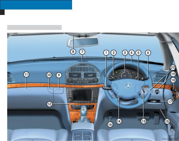
Multi-function steering wheel
|
Function |
Page |
|
|
1 |
Multi-function display |
130 |
|
Controlling the oper- |
130 |
ating system
2 Selects a submenu or adjusts the volume
æ Up /increases
the volume
ç Down/ decreases the volume
3 Making a phone call s Accepts a call
Starts dialling t Hangs up
Rejects an incoming call
4Jumps from one menu to another
è Forwards
ÿBack
5Scrolls within a menu j Forwards k Back
|
24 |
Online Version (Edition F1, 06/03) |

Centre console
Upper section
At a glance
Centre console
|
Function |
Page |
|
|
1 |
Controls Thermatic |
181 |
|
Controls 4-zone- |
192 |
|
|
Thermotronic* |
||
|
Switches the rear win- |
180 |
|
|
dow heating on/off |
||
|
2 |
Controls COMAND |
|
|
APS* and Audio sys- |
||
|
tem* – see the sepa- |
||
|
rate Operating |
||
|
Instructions |
||
|
3 |
Switches the seat |
117 |
|
heating* on the right- |
||
|
hand side on/off |
||
|
4 |
Switches the seat ven- |
116 |
|
tilation* on the right- |
||
|
hand side on/off |
||
|
5 |
Unlocks the vehicle |
104 |
|
6 |
Opening button for |
282 |
|
stowage compartment |
or CD changer* – see the separate Operating Instructions
|
Function |
Page |
|
|
7 |
Switches the seat ven- |
116 |
|
tilation* on the left- |
||
|
hand side on/off |
||
|
8 |
Switches the seat |
117 |
|
heating* on the left- |
||
|
hand side on/off |
||
|
9 |
Saloon: |
|
|
Rolls the rear window |
179 |
|
|
blind* up/down |
||
|
Estate: |
||
|
Switches the rear |
52 |
|
|
windscreen wiper |
||
|
on/off |
||
|
a |
Folds back the rear |
110 |
|
seat head restraints |
||
|
b |
Switches the hazard |
125 |
|
warning lamps on/off |
||
|
c |
Passenger airbag |
70 |
|
warning lamp |
||
|
d |
Locks the vehicle |
104 |
|
e |
Activates/deactivates |
79 |
|
ESP |
||
|
Online Version (Edition F1, 06/03) |
25 |
![]()
At a glance
Centre console
Lower section
|
Function |
Page |
|
|
1 |
Opens/closes |
287 |
|
the ashtray |
||
|
2 |
KEYLESS GO* button |
32 |
|
3 |
Manual transmission: |
163 |
|
Gear lever |
||
|
Automatic transmis- |
165 |
|
|
sion*: |
||
|
Selector lever |
||
|
4 |
Switches auxiliary |
207 |
|
heating* /ventilation* |
||
|
on/off |
||
|
5 |
Deactivates |
255 |
|
Parktronic* |
||
|
Function |
Page |
|
|
6 |
Sets Airmatic DC* |
250 |
|
7 |
Sets the vehicle’s |
248 |
|
level* |
||
|
8 |
Distronic*: |
234 |
|
Sets the specified |
||
|
minimum distance |
||
|
9 |
Distronic*: |
234 |
|
Switches the distance |
||
|
warning function* |
||
|
on/off |
||
|
a |
Automatic transmis- |
170 |
|
sion*: |
||
|
Selects the gearshift |
||
|
program |
||
|
26 |
Online Version (Edition F1, 06/03) |

Overhead control panel
|
Function |
Page |
|
|
1 |
Switches the rear inte- |
126 |
|
rior lights on/off |
||
|
2 |
Switches the interior |
126 |
|
lighting automatic |
||
|
function on/off |
||
|
3 |
Switches the front in- |
126 |
|
terior lighting on/off |
||
|
4 |
Switches the right- |
126 |
|
hand reading lamp |
||
|
on/off |
||
|
5 |
Opens/closes the |
213 |
|
sliding/tilting sun- |
||
|
roof* |
||
|
or |
||
|
Opens/closes the |
217 |
|
|
panorama sliding |
||
|
sunroof* |
||
|
6 |
Activates the TeleAid |
293 |
|
emergency call |
||
|
system* |
||
At a glance
Overhead control panel
|
Function |
Page |
|
|
7 |
Primes/deactivates |
85 |
|
the interior motion |
||
|
sensor* |
||
|
8 |
Rear-view mirror |
39 |
|
175 |
||
|
9 |
Reading lamps |
126 |
|
a |
Transmitter buttons |
297 |
|
for the garage door |
||
|
opener* |
||
|
b |
Primes/deactivates |
84 |
|
tow-away protection* |
||
|
c |
Ambient lighting* |
126 |
|
d |
Interior light |
126 |
|
e |
Switches the left-hand |
126 |
|
reading lamp on/off |
||
|
Online Version (Edition F1, 06/03) |
27 |

At a glance
Door control panel
|
Function |
Page |
|
|
1 |
Opens the door |
95 |
|
2 |
Adjusts the seat elec- |
34 |
|
trically* |
||
|
3 |
Stores settings for the |
119 |
|
seat, exterior mirrors |
||
|
and steering wheel* |
||
|
4 |
Adjusts the exterior |
40 |
|
mirrors |
||
|
5 |
Opens/closes the side |
211 |
|
windows |
||
|
Function |
Page |
|
|
6 |
Saloon: |
|
|
Boot lid remote un- |
99 |
|
|
locking feature |
||
|
Saloon: |
||
|
Boot lid remote open- |
99 |
|
|
ing switch* for |
||
|
opening/closing the |
||
|
boot lid automatically |
||
|
Estate: |
||
|
Tailgate remote open- |
100 |
|
|
ing switch* for opening |
||
|
the tailgate automati- |
||
|
cally |
||
|
28 |
Online Version (Edition F1, 06/03) |

Getting started
Opening
The «Getting started» section contains brief details of the basic functions of the vehicle. You should read this section particularly thoroughly if this is your first Mercedes-Benz vehicle.
If you are already familiar with the basic functions described here, the «Controls in detail» section will help you with more detailed information. You will find the reference to the appropriate page number at the end of each section.
Unlocking with the remote control
Key with remote control
1 ‹ Locking button
2 Š Unlocking button for boot lid/tailgate*
3 ΠUnlocking button
Your vehicle can be started with the key. This can also be used to activate other functions, e.g. opening the windows.
Do not leave children unsupervised in the vehicle as they could accidentally activate these functions.
Therefore, take the key with you when leaving the vehicle, even if you are only leaving it for a short while.
|
30 |
Online Version (Edition F1, 06/03) |
Press the Œunlocking button on the remote control.
The turn signals flash once. The vehicle unlocks. The locking knobs in the doors pop up. The anti-theft alarm system* is deactivated. The surround lighting also comes on when it is dark if this function is enabled in the control system.
i
The SBC brake system is activated ( page 80).
Get into the vehicle and insert the key in the ignition lock.
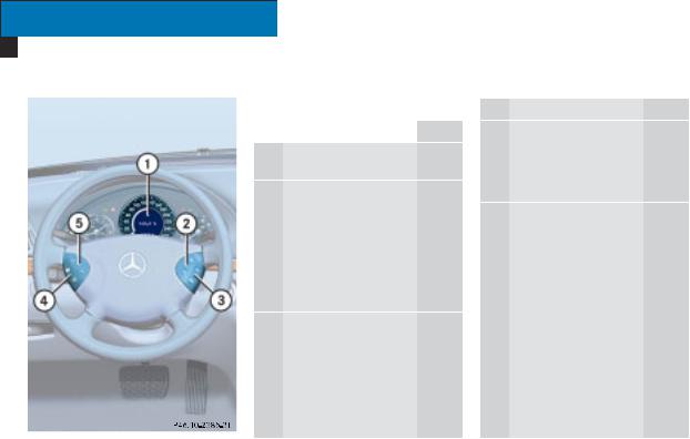
Key positions
Ignition lock
0 To remove the key
1Power supply for some consumers, such as the seat adjustment function
2Ignition (power supply for all consumers) and drive position
3 To start the engine ( page 45)
Getting started
Opening
i
The indicator and warning lamps light up when you switch on the ignition. They go out when the engine is running. This shows that the indicator and warning lamps for each system are operational.
You will find further information in the «Controls in detail» section
( page 88).
|
Online Version (Edition F1, 06/03) |
31 |

Unlocking with KEYLESS GO*
You can unlock and start your vehicle without the remote control button using KEYLESS GO.
i
The KEYLESS GO key must be outside the vehicle to unlock it.
Pull the door handle.
The turn signals flash once. The vehicle unlocks. The locking knobs in the doors pop up. The anti-theft alarm system* is deactivated. The surround lighting also comes on when it is dark if this function is enabled in the control system.
.
Your vehicle can be started using a valid KEYLESS GO key. This can also be used to activate other functions, e.g. adjusting the seats and opening the windows.
Do not leave children unsupervised in the vehicle as they could accidentally activate these functions.
Take the KEYLESS GO key with you when leaving the vehicle, even if you are only leaving it for a short while.
i
The SBC brake system is activated ( page 80).
Get into the vehicle.
KEYLESS GO positions
Pressing the KEYLESS GO button on the selector lever without depressing the brake pedal corresponds to the different key positions in the ignition lock ( page 31).
If you depress the brake pedal while pressing the KEYLESS GO button, the engine starts immediately.
i
If there is a key in the ignition lock, it has priority over the KEYLESS GO function.
|
32 |
Online Version (Edition F1, 06/03) |
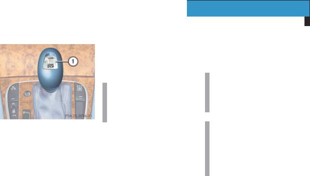
1 KEYLESS GO button
Position 0
The on-board electronics have the status 0, the same as the key having been removed from the ignition, until you press KEYLESS GO button 1.
Position 1
Press KEYLESS GO button 1once.
You can now adjust the seats, for example.
i
The power supply will be disconnected again if you press the KEYLESS GO button twice while this position is selected.
Position 2 (ignition)
Press KEYLESS GO button 1 twice.
i
The power supply will be disconnected again if you press the KEYLESS GO button once while this position is selected.
i
The indicator and warning lamps light up when you switch on the ignition. They go out when the engine is running. This shows that the indicator and warning lamps for each system are operational.
You will find further information in the «Controls in detail» section
( page 91).
|
Online Version (Edition F1, 06/03) |
33 |

Getting started
Adjusting
Seats
You can adjust the seats either electrically or manually, depending on your vehicle’s equipment.
Only adjust the driver’s seat when the vehicle is stationary. You will otherwise be distracted and could lose control of the vehicle and cause an accident as a result of the seat movement.
Make sure that nobody can be trapped as you adjust the seat.
Your seat must be adjusted in such a way that you can wear the seat belt correctly ( page 43).
Position your seat in such a way that:
You are seated as far as possible from the front airbag.
Ensure the following:
The backrest is almost vertical.
Your arms are slightly bent when you are holding the steering wheel.
The distance to the pedals is such that you can depress them fully and your legs are not completely outstretched.
The head restraint supports the back of your head at about eye level.
You could otherwise receive severe or even fatal injuries in the event of sudden braking or an accident.
|
34 |
Online Version (Edition F1, 06/03) |
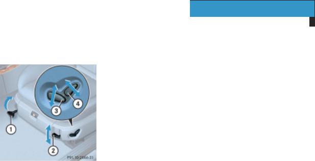
Adjusting the seat manually and electrically
1 Seat fore-and-aft adjustment
2 Seat cushion angle
3 Seat height
4 Backrest angle
Getting started
Adjusting
Seat fore-and-aft adjustment
Pull handle 1 up.
Push the seat forwards or backwards.
Release handle 1 again.
Make sure that you hear the seat click into position.
Seat cushion angle
Adjust the seat cushion angle so that your thighs are lightly supported.
Pull lever 2 upwards.
The seat cushion angle is tilted upwards by one detent.
or
Press the lever downwards.
The seat cushion angle is tilted downwards by one detent.
Seat height
Make sure that the key is in position 1 or 2 in the ignition lock.
Slide switch 3 up or down in the direction of the arrow.
Backrest angle
Make sure that the key is in position 1 or 2 in the ignition lock.
Slide switch 4 forwards or backwards in the direction of the arrow.
|
Online Version (Edition F1, 06/03) |
35 |
Getting started
Adjusting
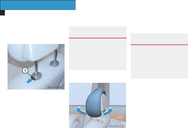
Head restraint height
The release catch is located on the top of the seat backrest.
1Release catch
Adjust the height of the head restraint manually. Press release catch 1 to lower the head restraint.
Make sure that the back of your head is supported by the centre of the head restraint at about eye level. This reduces the risk of injury to the head and neck in the event of an accident or similar situations.
Head restraint angle
Adjust the angle of the head restraint manually. Pull or push on the bottom of the head restraint.
Adjusting the seat electrically*
The seats can be adjusted when the key is removed from the ignition and the door is open.
For this reason, children should never be left unsupervised in the vehicle.
Make sure that:
the key is in position 1 or 2 in the ignition lock
or
the appropriate door is open
|
36 |
Online Version (Edition F1, 06/03) |
![]()
Getting started
Adjusting
The switches are located on the door control panel.
1 Seat fore-and-aft adjustment
2 Backrest angle
3 Head restraint height
4 Seat height
5 Seat cushion angle
Seat fore-and-aft adjustment
Slide switch 1 forwards or backwards in the direction of the arrow.
Seat height
Slide switch 4 up or down in the direction of the arrow.
Seat cushion angle
Slide switch 5 up or down in the direction of the arrow until your thighs are lightly supported.
Backrest angle
Slide switch 2 forwards or backwards in the direction of the arrow.
Head restraint height
Slide switch 3 up or down in the direction of the arrow.
Make sure that the back of your head is supported by the centre of the head restraint at about eye level. This reduces the risk of injury to the head and neck in the event of an accident or similar situations.
Head restraint angle
-2116-31
Adjust the angle of the head restraint manually. Pull or push on the bottom of the head restraint.
|
Online Version (Edition F1, 06/03) |
37 |
Getting started
Adjusting
Steering wheel
Risk of accident G
Only adjust the steering wheel when the vehicle is stationary. Only drive with the steering wheel locked in position.
The electrically-adjustable steering wheel* can be adjusted when the key is removed from the ignition and the door is open.
Do not, therefore, leave children unsupervised in the vehicle as they could be trapped as the steering wheel is adjusted.
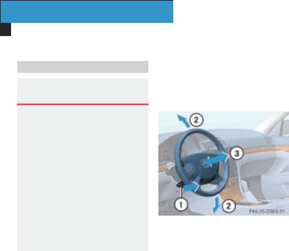
Adjusting the steering wheel manually
The handle is located under the steering column.
1 Release handle
2 Steering column height
3 Steering column fore-and-aft adjustment
Pull handle 1 out completely. The steering column is unlocked.
Adjust the steering wheel to the required position.
When doing this make sure that:
The steering wheel can be reached with your arms slightly bent
Your legs can move freely
All the displays in the instrument cluster can be clearly seen
Push handle 1 in fully until you hear it engage fully.
The steering wheel position is locked.
|
38 |
Online Version (Edition F1, 06/03) |

Getting started
Adjusting
Adjusting the steering wheel electrically*
The lever is located on the left under the steering wheel.
1Steering column fore-and-aft adjustment
2Steering column height
Make sure that:
the key is in position 1 or 2 in the ignition lock
or
the appropriate door is open
Steering column fore-and-aft adjustment
Push the lever forwards or backwards in the direction of arrow 1 until your arms are slightly bent when you are holding the steering wheel.
Steering column height
Push the lever up or down in the direction of arrow 2. When doing this make sure that:
You can move your legs freely
You can see all the displays in the instrument cluster clearly
You will find further information in the «Controls in detail» section:
Easy-entry system for the driver ( page 106)
Storing the steering wheel position ( page 119)
Mirrors
Before starting off, adjust the rear-view mirror and the exterior mirrors so that you get a good overview of road and traffic conditions.
Rear-view mirror
Adjust the rear-view mirror manually.
|
Online Version (Edition F1, 06/03) |
39 |

Getting started
Adjusting
|
Exterior mirrors |
The buttons are located on the door |
|
control panel. |
|
|
Risk of accident |
G |
The exterior mirrors reduce the size of the image. The objects are actually closer than they appear.
1 Right-hand exterior mirror
2 Left-hand exterior mirror
3 Adjustment button
Make sure that the ignition is switched on.
All the lights in the instrument cluster are lit.
Press button 1 for the right-hand mirror or button 2for the left-hand mirror.
Press adjustment button 3 at the top or bottom or to the right or to the left until you have adjusted the mirror to the correct position.
i
The convex exterior mirrors give a larger field of view.
Your exterior mirrors are automatically heated at low outside temperatures.
You will find further information in the «Controls in detail» section
( page 175).
|
40 |
Online Version (Edition F1, 06/03) |

Driving
Do not keep any objects in the driver’s footwell. Make sure that floormats or carpets in the driver’s footwell
do not obstruct the pedals
are securely fastened
Objects could otherwise get caught between the pedals if you accelerate or brake suddenly. You will then not be able to brake, operate the clutch pedal, or accelerate as intended. This could lead to accidents and injury.
Wearing seat belts
Risk of injury G
A seat belt which is not worn correctly, or which has not been engaged in the seat belt buckle correctly, cannot perform its intended protective function. Under certain circumstances this could even cause severe or fatal injuries.
Make sure that all occupants – especially pregnant women – wear their seat belts correctly at all times:
Getting started
Driving
The seat belt must pass closely over your body and must not be twisted. You should therefore avoid wearing bulky clothing (e.g. winter coats). The shoulder belt section must be routed over the middle of your shoulder – never over your neck or under your arm – and pulled tight against your upper body. The lap belt must cross over your lap as low down as possible at all times, i.e. over your hip joints – not across your stomach or lower abdomen. If necessary, tighten the belt strap by pulling it down slightly and retighten in the direction of the inertia reel.
Do not route the belt strap over sharp-edged or easily broken objects, especially if these are located on or in your clothing, e.g. spectacles, pencils, keys, etc. The seat belt strap could be damaged and you could be injured.
|
Online Version (Edition F1, 06/03) |
41 |

Getting started
Driving
Only one person should use each seat belt at any one time. Never carry children on your lap, since the child will then no longer be secured in the event of an accident, braking or a sudden change in direction, which could result in severe or fatal injuries to the child and other occupants.
Persons less than 1.50 m tall (5 feet) cannot wear the seat belts correctly. For this reason, secure persons less than 1.50 m (5 feet) tall in specially designed, suitable restraint systems.
Children less than 1.50 m
(5 feet) tall or under 12 years of age cannot wear the seat belts properly. Always secure these children in suitable child re-
straint systems on suitable vehicle seats ( page 66).
Follow the manufacturer’s installation instructions when fitting the child restraint system.
Do not secure any objects with a seat belt if it is also being used by one of the vehicle’s occupants.
A seat belt only offers its intended degree of protection if the backrest is positioned as close to the vertical as possible and the occupant is sitting upright. Avoid seat positions that do not allow the seat belt to be routed correctly ( page 34). Position the backrest as vertically as possible. Do not drive with the backrest reclined too far back.
By design, airbags are not activated in all accident situations, since a correctly fastened seat belt will often be sufficient for providing an effective degree of protection. Airbags do not replace seat belts in any way. To reduce the risk of serious or fatal injuries, make sure that all occupants – especially pregnant women
– are strapped in correctly at all times, have adopted a normal sitting position, and that the seat is positioned as close to the vertical as possible ( page 34).
|
42 |
Online Version (Edition F1, 06/03) |

1 Belt reel
2 Belt tongue
3 Buckle
4 Release button
Pull the belt smoothly from belt reel 1.
Route the belt over your shoulder.
Click belt tongue 2into buckle 3.
If necessary, adjust the belt to the correct height ( page 44).
Pull the shoulder belt upwards to tighten the belt across your lap if necessary.
You could be injured in an accident if you use seat belts which:
are damaged
have been subjected to a load in an accident
have been modified
Getting started
Driving
The seat belts can then neither function nor perform their protective function as intended.
Do not route the belt strap over sharp edges. It could tear.
Make sure that the seat belt is not caught in the door or in the seat adjustment mechanism. It could be damaged.
Check regularly that the seat belts are not damaged.
Never carry out any modifications to the seat belts yourself. They might not function properly any more.
Always have seat belts which have been damaged or subjected to a heavy load in an accident replaced at a qualified specialist workshop which has the necessary specialist knowledge and tools to carry out the work required.
|
Online Version (Edition F1, 06/03) |
43 |
Getting started
Driving
Mercedes-Benz recommends a Mercedes-Benz Service Centre for this purpose. In particular, work relevant to safety or on safety-related systems must be carried out at a qualified specialist workshop.
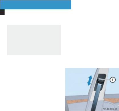
Belt height adjustment
You can adjust the seat belt height on the following seats:
Driver’s seat
Front-passenger seat
Outer rear seats
Adjust the height so that the belt passes over the middle of your shoulder.
Raising the belt
Push the belt guide up.
The belt guide will engage in various positions.
Lowering the belt
Press and hold release button 1.
Move the belt guide to the required height.
Let go of release button 1 and ensure that the belt guide has engaged.
Please observe the information on wearing seat belts correctly
( page 41).
1 Release button
|
44 |
Online Version (Edition F1, 06/03) |

Starting the engine
Risk of poisoning G
Never leave the engine running in enclose spaces. The exhaust gases contain carbon monoxide. Inhaling exhaust fumes constitutes a health hazard and could lead to loss of consciousness or even death.
!
Do not depress the accelerator pedal when starting the engine.
i
If you depress the brake when starting the engine, the pedal travel is longer than usual and the pedal resistance is low.
If you depress the brake after starting the engine, the pedal travel and pedal resistance return to normal.
Automatic transmission*
Gearshift pattern
PPark position with selector lever
lock
R Reverse gear N Neutral
D Drive position
Before starting the engine, make sure that the selector lever is in position P.
You will find further information about automatic transmission in the «Controls in detail» section ( page 165).
Getting started
Driving
Starting the engine with the key
Vehicles with a petrol engine
Turn the key to position 3 in the ignition lock ( page 31) and release
it.
The engine starts automatically.
Vehicles with a diesel engine
Turn the key to position 2 in the ignition lock ( page 31).
The qpreglow indicator lamp in the instrument cluster lights up.
As soon as the qpreglow indicator lamp goes out, turn the key to position 3 in the ignition lock and release it.
The engine starts automatically.
i
You can start the engine without preglow if the engine is warm.
|
Online Version (Edition F1, 06/03) |
45 |

Starting the engine with KEYLESS GO*
Your vehicle can be started as long as the KEYLESS GO key is in the vehicle. For this reason, children should never be left unsupervised in the vehicle. They could unintentionally start the vehicle.
Take the KEYLESS GO key with you when leaving the vehicle, even if you are only leaving it for a short while.
You may start your vehicle with no key in the ignition lock using the KEYLESS GO button on the selector lever.
1 KEYLESS GO button
Vehicles with a petrol engine
Depress the brake pedal.
The selector lever lock will be released.
Press KEYLESS GO button 1once. The engine starts automatically.
Vehicles with a diesel engine
Depress the brake pedal.
The selector lever lock will be released.
Press KEYLESS GO button 1once.
Preglow is activated and the engine starts automatically.
You can start the engine without preglow if the engine is warm:
Press and hold KEYLESS GO button 1 until the engine is running.
|
46 |
Online Version (Edition F1, 06/03) |
![]()
6-speed manual transmission
Gearshift pattern
1 – 6 Forward gears
RReverse gear
Before starting the engine, make sure that the transmission is in neutral.
Apply the parking brake ( page 47).
You will find further information about 6-speed transmission in the «Controls in detail» section ( page 163).
Starting the petrol engine
Turn the key to position 3 in the ignition lock ( page 31) and release
it as soon as the engine is running.
Starting the diesel engine
Turn the key to position 2 in the ignition lock ( page 31).
The qpreglow indicator lamp in the instrument cluster lights up.
As soon as the qpreglow indicator lamp goes out, turn the key to position 3 in the ignition lock and release it as soon as the engine is running.
i
You can start the engine without preglow if the engine is warm.
Getting started
Driving
Parking brake
-31
1 Parking brake
2 Release handle
Never leave children unsupervised in the vehicle. They could release the parking brake. This could lead to a serious or fatal accident.
|
Online Version (Edition F1, 06/03) |
47 |

Getting started
Driving
Depress the brake pedal and hold it down.
On vehicles with automatic transmission* the selector lever lock is released.
Release the parking brake. To do this, pull handle 2.
The 3indicator lamp in the instrument cluster goes out.
i
The SBC brake system is activated ( see page 80).
Pulling away
!
Reverse gear may only be selected when the vehicle is stationary, otherwise the transmission could be damaged.
Do not drive at high engine speeds until the engine has warmed up. This will protect the engine.
i
The vehicle will lock itself centrally once you have pulled away. The locking knobs in the doors drop down.
You can open the doors from the inside at any time.
You can also switch off the automatic door lock ( page 152).
Automatic transmission*
Apply the brake.
The selector lever lock will be released.
Move the selector lever to position D or R.
i
Wait for the shift process to complete before pulling away.
Carefully press the accelerator pedal.
Upshifts take place at higher engine speeds after a cold start. This helps the catalytic converter to reach its operating temperature more quickly.
6-speed manual transmission
Depress the clutch pedal.
Select either first or reverse gear.
Release the clutch pedal slowly and depress the accelerator pedal.
!
Change gear in good time and do not exceed the maximum speed for each gear ( page 450).
Wherever possible, avoid letting the wheels spin. You could otherwise damage the drive train.
|
48 |
Online Version (Edition F1, 06/03) |

Do not downshift until the speed at which you are driving is within the permissible range for the required gear.
Do not change down for additional engine braking on a slippery road surface. The drive wheels could lose traction and the vehicle could skid. You could lose control of your vehicle and cause an accident.
Switching on the headlamps
Dipped-beam headlamps
The light switch is located between the steering wheel and the driver’s door.
Getting started
Driving
i
On some country-specific vehicle models, the dipped-beam headlamps come on as soon as the ignition is switched on.
Main-beam headlamps
The combination switch is located on the left of the steering wheel.
-31
Light switch
1 Lights off
2 Dipped-beam headlamps on
Turn the light switch to B.
Combination switch
1 Main-beam headlamps
2 Headlamp flash
|
Online Version (Edition F1, 06/03) |
49 |

Press the combination switch forwards 1.
The main-beam headlamps come on.
The Amain-beam indicator lamp in the instrument cluster lights up.
You will find further information about the lights in the «Controls in detail» section ( page 121).
Turn signals
The combination switch is located on the left of the steering wheel.
Combination switch
1 Right-hand turn signal
2 Left-hand turn signal
50
Push the combination switch up 1 or down 2.
The corresponding turn signal indicator lamp flashes in the instrument cluster.
The combination switch returns to its original position automatically after large steering movements.
i
Press the combination switch briefly to indicate a minor change in direction. The appropriate turn signal will flash three times.
Windscreen wipers
The combination switch is located on the left of the steering wheel.
-31
Combination switch
1 Single wipe
2To switch on the windscreen wipers
Make sure that the ignition is switched on.
Online Version (Edition F1, 06/03)

Switching on the windscreen wipers
Turn the combination switch to the correct setting depending on the intensity of the rain.
0 Windscreen wipers off
IIntermittent wipe (the wiper sweep interval is dependent on how heavy the rain is)
II Normal wipe
III Rapid wipe
i
You can use position I as the universal position. The appropriate wiping frequency is set automatically, depending on the intensity of the rain.
Single wipe
Push the combination switch briefly up to the pressure point in the direction of arrow 1.
The windscreen wipers will wipe once without windscreen washer fluid.
Wiping the windscreen using washer fluid
Push the combination switch beyond the pressure point in the direction of arrow 1.
The windscreen wipers will wipe with windscreen washer fluid.
i
Wipe the windscreen using windscreen washer fluid even when it is raining. By doing so, you will avoid smears on the windscreen.
Intermittent wipe
i
If you have selected the intermittent setting, wiping is interrupted as soon as the driver’s door or front-passenger door is opened. This protects people getting into and leaving the vehicle from being sprayed with water.
Intermittent wipe continues when the doors are closed again and:
when the clutch is depressed on vehicles with manual transmission
when the selector lever is moved to D or R on vehicles with automatic transmission*
The rain sensor controls the windscreen wipers automatically depending on the intensity of the rain.
Make sure that the ignition is switched on.
Set the combination switch to position I.
There will be one wiper sweep and the wipe intervals will then be controlled according to the intensity of the rain.
|
Online Version (Edition F1, 06/03) |
51 |

Rear window wiper for Estate
The switch is located on the centre console.
1 Intermittent wipe
2 Indicator lamp
3Rear window washer system
Make sure that the ignition is switched on.
i
The rear window wiper comes on automatically if you engage reverse gear while the windscreen wipers are on.
Switching on intermittent wipe
Press upper section 1 of the switch.
Indicator lamp 2 lights up.
Switching off intermittent wipe
Press upper section 1 of the switch again.
Indicator lamp 2 goes out.
Wiping with washer fluid
Press and hold lower section 3 of the switch.
The rear window is wiped for a further five seconds after the switch is released.
|
52 |
Online Version (Edition F1, 06/03) |

Parking and locking
You have now completed your first trip. You have stopped your vehicle and have parked properly. End your journey as follows.
Only remove the key from the ignition lock when the vehicle is stationary since you cannot steer the vehicle with the key removed.
Never leave children unsupervised in the vehicle. They could release the parking brake. This could lead to a serious or fatal accident.
Make sure that the exhaust system does not come into contact with easily ignitable material such as dry grass or petrol. The material could otherwise ignite and set parts of the vehicle alight.
Getting started
Parking and locking
Parking brake
-31
1 Parking brake
2 Release handle
Depress parking brake 1 firmly.
The 3indicator lamp in the instrument cluster lights up if the engine is running.
i
On steep slopes, turn the front wheels towards the kerb.
|
Online Version (Edition F1, 06/03) |
53 |

Getting started
Parking and locking
Stopping the engine
Vehicles with 6-speed manual transmission
Select either first or reverse gear.
Turn the key to position 0 in the ignition lock ( page 31) and remove
it.
The immobiliser is activated.
Press the seat belt release button
and guide the belt tongue back to the seat belt guide ( page 43).
Vehicles with automatic transmission*
Move the selector lever to P.
With the key
Turn the key to position 0 in the ignition lock ( page 31) and remove
it.
The immobiliser is activated.
i
The key can only be removed when the selector lever is in position P.
Press the seat belt release button
and guide the belt tongue back to the seat belt guide ( page 43).
With KEYLESS GO*
Press the KEYLESS GO button on the selector lever.
The engine stops and all the lights in the instrument cluster go out.
The on-board electronics have the status 1 ( page 31).
Press the seat belt release button
and guide the belt tongue back to the seat belt guide ( page 43).
|
54 |
Online Version (Edition F1, 06/03) |

Locking
Risk of injury G
Make sure that nobody can be trapped as you close the doors.
Get out of the vehicle and close the doors.
Locking with the remote control
Press the ‹locking button on the remote control ( page 30).
The locking knobs in the doors drop down. The turn signals flash three times.
Locking with KEYLESS GO*
Getting started
Parking and locking
Press locking button 1on the door handle.
The locking knobs in the doors drop down. The turn signals flash three times.
The immobiliser is activated.
i
The on-board electronics have the status 0 after the door is opened, the same as the key having been removed from the ignition.
You will find further information about closing in the «Controls in detail» section ( page 91).
1 Locking button on the door handle
|
Online Version (Edition F1, 06/03) |
55 |

Safety
Occupant safety
This section contains all the most important information about your vehicle’s restraint systems.
The restraint systems are:
Seat belts
Belt tensioners and belt force limiters
Airbags
Child seats
Child seat recognition
As independent systems, their protective functions complement one another.
Work incorrectly carried out on the restraint systems could cause them to be triggered inadvertently or not at all.
Always have service work carried out at a qualified specialist workshop which has the necessary specialist knowledge and tools to carry out the work required. MercedesBenz recommends a Mercedes-Benz Service Centre for this purpose. In particular, work relevant to safety or on safety-related systems must be carried out at a qualified specialist workshop.
Airbags
Risk of injury G
Airbags can provide additional protection in conjunction with a correctly fastened seat belt. However, they are not an alternative to the seat belts.
To reduce the risk of severe or even fatal injuries caused by the airbags inflating in an accident with deceleration exceeding a predetermined level, please make sure that:
all occupants – especially pregnant women – wear their seat belts correctly for every trip.
Choose a seat position as far back as possible from the airbag, but which still allows you to drive the vehicle safely.
|
58 |
Online Version (Edition F1, 06/03) |
![]()
Do not lean forward during the journey.
Do not lean on the doors from inside the vehicle.
Do not put your feet on the dashboard.
Only hold the steering wheel by the rim. This allows the airbag to inflate fully.
Do not place any objects on the airbags or between the airbags and the vehicle’s occupants.
Do not place any objects on the airbags or between the airbags and the vehicle’s occupants.
Do not hang any hard objects, for example coat hangers, on the grab handles.
Correct operation of the airbags can only be guaranteed if:
the front seats are not covered.
nothing is placed under the seat surface of the front-passenger seat.
the padded boss of the steering wheel, the front-passenger airbag cover, the door trim, the side trim in the rear and the roof lining in the area of the windowbags are not covered and no stickers or badges are affixed.
the restraint systems, including the wiring, have not been modified.
the seats have not been removed, dismantled or modified.
Safety
Occupant safety
After an airbag has been triggered:
Do not touch any airbag parts. They may be hot.
The airbags in this vehicle deploy in two stages. Therefore an airbag which has been triggered could still inflate.
Have the airbags replaced at a qualified specialist workshop which has the necessary specialist knowledge and tools to carry out the work required. Mercedes-Benz recommends a Mercedes-Benz Service Centre for this purpose. In particular, work relevant to safety or on safety-related systems must be carried out at a qualified specialist workshop.
|
Online Version (Edition F1, 06/03) |
59 |

Safety
Occupant safety
The airbags will only be able to perform their intended protective function if the occupants are wearing their seat belts correctly
( page 41).
Airbags inflate within milliseconds and can therefore cause injury:
if the seats are positioned very near to the front airbags.
This position is particularly dangerous for small children and babies in rearward-facing child seats on the front-passenger seat. Therefore, only use the special Mercedes-Benz child
seat with sensor system (transponder) ( page 70) or fit the
rearward-facing child seat on a rear seat.
Forward-facing child seats without transponder should only be used with the front-passenger seat in its rearmost position.
if occupants behave inappropriately or foolishly.
Occupants, particularly small children, can be severely or fatally injured as a result of inappropriate behaviour or if they are in the immediate vicinity of the front-airbag inflation.
Mercedes-Benz recommends that you only use the child restraint systems listed ( see page 65).
If you sell your vehicle, you are under the obligation to make the buyer aware of these points. You should therefore pass on this Owner’s Manual to the new owner for this purpose.
Comply with safety regulations when disposing of airbag units. Details of these regulations are available at any Mercedes-Benz Service Centre.
If an airbag is triggered, smoke is emitted as it inflates. This smoke does not constitute a health hazard, nor does it imply that a fire has broken out in the vehicle.
The fabric of the airbags can cause minor abrasions as they inflate rapidly.
|
60 |
Online Version (Edition F1, 06/03) |

For safety reasons, Mercedes-Benz recommends that you use seat covers which have been tested by Mercedes-Benz and which have a special tear seam for sidebags. These are available from any Mercedes-Benz Service Centre.
The 1indicator lamp in the instrument cluster lights up:
for about four seconds if you turn the key to position 1 in the ignition lock. It then goes out briefly and lights up again permanently
permanently if the key is turned to position 2 in the ignition lock. It goes out if you start the engine
The restraint systems are fully operational if the 1indicator lamp is not lit when the engine is running.
Front airbags
The airbags will not trigger in a minor front-end collision. The seat belts will provide the necessary protection in this case.
The driver’s airbag and front-passenger airbag are triggered in an accident where the front-end is subjected to high acceleration, e.g. a head-on collision.
Safety
Occupant safety
The front-passenger airbag will only be triggered if:
the front-passenger seat is occupied and
the PASSENGER AIRBAG OFF warn-
ing lamp on the centre console is not lit ( page 70).
-31
1 Driver’s airbag
2 Front-passenger airbag
|
Online Version (Edition F1, 06/03) |
61 |

!
Do not place heavy objects on the front-passenger seat. These could cause the front-passenger airbag and the front-passenger sidebag to be triggered in an accident.
Sidebags* and windowbags
Saloon
1 Windowbag
2 Rear sidebag*
3 Front sidebag
Estate
1 Windowbag
2 Rear sidebag*
3 Front sidebag
Sidebags*
The sidebags are triggered in an accident:
in which there is high lateral acceleration, e.g. a side impact
on the side on which an impact occurs
The sidebags will not be triggered in a minor side impact.
The front-passenger sidebag will only be triggered if the front-passenger seat has heavy objects placed on it or if it is actually occupied.
Windowbags
The windowbags are triggered in an accident:
in which there is high lateral acceleration, e.g. a side impact
on the side on which an impact occurs
if the vehicle overturns, in those cases where their deployment would offer the vehicle’s occupants additional protection
The windowbags inflate in the area between the A and C pillars (arrows).
|
62 |
Online Version (Edition F1, 06/03) |

Seat belts
In many countries there are laws concerning the use of seat belts and child restraint systems. All occupants should always use the seat belts regardless of these regulations.
You will find information about fastening the seat belts in the «Getting started» section ( page 41).
Have seat belts which have been damaged or subjected to heavy loads in an accident replaced and have their anchorages checked.
For safety reasons, Mercedes-Benz recommends that you only use seat belts which have been specially approved by Mercedes-Benz for your vehicle.
Never modify seat belts in any way. This can cause the belt tensioners to trigger inadvertently or the seat belts to fail.
Always have work on seat belts carried out at a qualified specialist workshop which has the necessary specialist knowledge and tools to carry out the work required. Mercedes-Benz recommends a Mercedes-Benz Service Centre for this purpose. In particular, work relevant to safety or on safety-related systems must be carried out at a qualified specialist workshop.
Safety
Occupant safety
Belt tensioners, belt force limiters
The front seat belts and the two outside rear seat belts are equipped with belt tensioners and belt force limiters.
These take effect:
provided the ignition is switched on
in front-end and rear-end collisions where the force of the collision exceeds a predetermined level
in certain situations if the vehicle overturns
Belt tensioners tighten the seat belts in an accident, pulling them close against the body. Belt force limiters reduce the load exerted by the seat belts on the occupants in an accident.
|
Online Version (Edition F1, 06/03) |
63 |

Safety
Occupant safety
Have belt tensioners which have been triggered replaced at a qualified specialist workshop which has the necessary specialist knowledge and tools to carry out the work required. Mercedes-Benz recommends a Mercedes-Benz Service Centre for this purpose. In particular, work relevant to safety or on safety-related systems must be carried out at a qualified specialist workshop.
Comply with safety regulations when disposing of belt tensioners. Details of these regulations are available at any Mercedes-Benz Service Centre.
!
Do not fasten a seat belt if you do not intend to secure a person or a load. The belt tensioners could be triggered in an accident if the seat belt tongue is engaged in the buckle.
Children in the vehicle
If a child is travelling in your vehicle:
secure the child using a child restraint system which is appropriate to his/her age and size and which has been approved for MercedesBenz, preferably on a suitable rear seat
make sure that the child is strapped in throughout the trip
Child seats and information about the correct child restraint system are available from any Mercedes-Benz Service Centre.
Never leave children alone in your vehicle. They could otherwise, for example, set the vehicle in motion, injure themselves on moving parts or open the doors, thus endangering themselves and others.
Also observe:
SBC Stop ( page 242)
SBC Hold ( page 246)
Observe the other warnings in this Owner’s Manual concerning children in the vehicle.
|
64 |
Online Version (Edition F1, 06/03) |

Child restraint systems
Mercedes-Benz recommends that you only use the child restraint systems listed on page 68.
You can recognise child seats in the «Universal» category from the orange approval label. The label is attached to the child seat and denotes what type it is.
Children under 1.50 m (5 feet) tall or under 12 years of age cannot wear the seat belts properly. They therefore need special restraint systems for protection in an accident.
On no account should children travel sitting on the lap of another occupant. The occupant and the child will otherwise not be protected in an accident and could be seriously or fatally injured.
Follow the manufacturer’s installation instructions when fitting a child restraint system.
Example of a child seat approval
label
|
Online Version (Edition F1, 06/03) |
65 |

Safety
Occupant safety
Suitable seat positions
Saloon
|
Weight category and |
Child seat on the |
Child seat on left |
Child seat on centre |
Child seat on centre |
|
ages |
front-passenger |
and right rear seat |
rear seat without |
rear seat with |
|
seat |
through-loading |
through-loading |
||
|
feature |
feature |
|||
|
Category 0: up to |
As recommended1 |
Universal |
Universal |
As recommended |
|
10 kg |
||||
|
up to approximately |
||||
|
9 months |
||||
|
Category I: 9 to 18 kg |
Universal2 |
Universal |
Universal |
Universal3 |
|
approximately 8 |
||||
|
months up to 4 years |
||||
|
Category II/III: |
Universal2 |
Universal |
Universal |
Universal3 |
|
15 kg to 36 kg |
||||
|
approximately 3.5 to |
||||
|
12 years |
||||
1 Only use child seats with automatic child seat recognition.
2 If you are using a child seat without automatic child seat recognition, move the front-passenger seat to its rearmost position. 3 Forward-facing child seat in the «Universal» category.
4 Do not use a rearward-facing child seat.
|
66 |
Online Version (Edition F1, 06/03) |

Safety
Occupant safety
Estate
|
Weight category and |
Child seat on the |
Child seat on left, |
Child seat on bench |
|
ages |
front-passenger |
right and centre |
seat |
|
seat |
rear seat |
||
|
Category 0: up to |
As recommended1 |
Universal |
Not permissible |
|
10 kg |
|||
|
up to approximately |
|||
|
9 months |
|||
|
Category I: 9 to 18 kg |
Universal2 |
Universal |
As recommended4 |
|
approximately 8 |
|||
|
months up to 4 years |
|||
|
Category II/III: |
Universal2 |
Universal |
No child seat required |
|
15 kg to 36 kg |
|||
|
approximately 3.5 to |
|||
|
12 years |
|||
1 Only use child seats with automatic child seat recognition.
2 If you are using a child seat without automatic child seat recognition, move the front-passenger seat to its rearmost position.
3 Forward-facing child seat in the «Universal» category. 4 Do not use a rearward-facing child seat.
|
Online Version (Edition F1, 06/03) |
67 |

Safety
Occupant safety
Recommended child restraint systems
|
Weight category |
Manufacturer |
Type |
Approval number |
DaimlerChrysler |
Automatic child seat |
|
|
and ages |
number |
recognition |
||||
|
Category 0: up to |
Britax Römer |
Baby |
E1 03 301063 |
B6 6 86 8159 |
Yes |
|
|
10 kg |
Safe |
|||||
|
up to approximately |
||||||
|
9 months |
||||||
|
Category I: 9 to |
Britax Römer |
Prince |
E1 03 301096 |
B6 6 86 8167 |
No1 |
|
|
18 kg |
B6 6 86 8168 |
Yes |
||||
|
approximately |
||||||
|
Britax Römer |
Duo |
E1 03 301133 |
B6 6 86 8205 |
Yes |
||
|
8 months to 4 years |
||||||
|
Category II/III: |
Britax Römer |
Zoom |
E1 03 301061 |
B6 6 86 8166 |
No1 |
|
|
15 kg to 36 kg |
B6 6 86 8176 |
Yes |
||||
|
approximately 3.5 to |
||||||
|
Bingo GmbH |
Rucky |
E1 03 301107 |
B6 6 86 8180 |
No1 |
||
|
12 years |
||||||
1If you are using a child seat without automatic child seat recognition, move the front-passenger seat to its rearmost position.
|
68 |
Online Version (Edition F1, 06/03) |
 Loading…
Руководство по эксплуатации и техническому обслуживанию автомобиля Mercedes-Benz серии W211.
Рекомендуем перед началом ремонта или обслуживания изучить руководство, это позволит избежать проблем при эксплуатации и узнать о всех функциях и особенностях автомобиля.
manual-z1sl-rukovodstvo-po-ekspluatacii-mercedes-benz-serii-w211
◀Скачать ТО и ремонт Mercedes W123 1976-1985 г
Скачать Автомобили Mercedes-Ben▶
-
#6
Руководство по ремонту Mercedes Benz W211 E-class
Уважаемые владельцы автомобиля Mercedes Benz W211 E-class!
В скором времени выходит книга по ремонту, эксплуатации и техническому обслуживанию автомобилей Mercedes Benz E-класса (W211) с 2002 г. выпуска. Пособие включает в себя подробные сведения по ремонту систем и агрегатов автомобиля.
В знак уважения к участникам форума, всем форумчанам предоставляется 10 процентная скидка при приобретении данного руководства и обеспечивается бесплатная почтовая доставка книги в любую точку РФ или бесплатная курьерская доставка в любую точку Москвы.
Последнее редактирование модератором: 1 Июл 2015