Table of Contents
Cisco Aironet 2600 Series Access Points
About this Guide
Introduction to the Access Point
Safety Instructions
Unpacking
Configurations
External Antennas
Internal Antennas
Regulatory Domains
Countries Supported
Access Point Ports and Connectors
Configuring the Access Point
The Controller Discovery Process
Preparing the Access Point
Installation Summary
Performing a Pre-Installation Configuration
Pre-Installation Configuration Setup
Mounting the Access Point
Deploying the Access Point on the Wireless Network
Troubleshooting
Guidelines for Using Cisco Aironet Lightweight Access Points
Using DHCP Option 43
Checking the Access Point LED
Troubleshooting the Access Point Join Process
Declarations of Conformity and Regulatory Information
Manufacturers Federal Communication Commission Declaration of Conformity Statement
VCCI Statement for Japan
Guidelines for Operating Cisco Aironet Access Points in Japan
Japanese Translation
English Translation
Statement 371—Power Cable and AC Adapter
English Translation
Industry Canada
Canadian Compliance Statement
European Community, Switzerland, Norway, Iceland, and Liechtenstein
Declaration of Conformity with regard to the R&TTE Directive 1999/5/EC & Medical Directive 93/42/EEC
Declaration of Conformity for RF Exposure
Generic Discussion on RF Exposure
This Device Meets International Guidelines for Exposure to Radio Waves
This Device Meets FCC Guidelines for Exposure to Radio Waves
This Device Meets the Industry Canada Guidelines for Exposure to Radio Waves
Cet appareil est conforme aux directives internationales en matière dqexposition aux fréquences radioélectriques
Additional Information on RF Exposure
Administrative Rules for Cisco Aironet Access Points in Taiwan
Chinese Translation
English Translation
Chinese Translation
English Translation
Operation of Cisco Aironet Access Points in Brazil
Access Point Models
Regulatory Information
Portuguese Translation
English Translation
Declaration of Conformity Statements
Configuring DHCP Option 43 and DHCP Option 60
Access Point Specifications
Obtaining Documentation and Submitting a Service Request
Getting Started Guide
About this Guide
This Guide provides instructions on how to install and configure your Cisco Aironet 2600 Series Access Point. The 2600 Series Access Point is referred to as the 2600 series or the access point in this document.
Introduction to the Access Point
The 2600 series supports high-performing Spectrum Intelligence which sustains three spatial stream rates over a deployable distance with high reliability when serving clients. The 2600 series provides high reliability and overall wireless performance.
The 2600 series offers dual-band radios (2.4 GHz and 5 GHz) with integrated and external antenna options. The access points support full inter-operability with leading 802.11n clients, and support a mixed deployment with other access points and controllers.
The 2600 series access point is available in both controller-based (Unified) and standalone (Autonomous) configurations and supports:
- Simultaneous single-band or dual-band (2.4 GHz/5 GHz) radios
- Integrated antennas on the 2602I access point model (AIR-CAP2602I-x-K9)
- External antennas for the rugged 2602E access point model (AIR-CAP2602E-x-K9)

Note![]() The ‘x’ in the model numbers represents the regulatory domain. For information on supported regulatory domains, see “Regulatory Domains” section.
The ‘x’ in the model numbers represents the regulatory domain. For information on supported regulatory domains, see “Regulatory Domains” section.
The features of the 2600 series are:
- Processing sub-systems (including CPUs and memory) and radio hardware which supports:
–![]() Network management
Network management
–![]() CleanAir—Automatic detection, classification, location and mitigation of RF interference (not available on autonomous or standalone models)
CleanAir—Automatic detection, classification, location and mitigation of RF interference (not available on autonomous or standalone models)
–![]() ClientLink 2.0—BeamForming to 802.11n clients as well as legacy 802.11a/g OFDM clients
ClientLink 2.0—BeamForming to 802.11n clients as well as legacy 802.11a/g OFDM clients
–![]() VideoStream (available only in WGB mode for autonomous or standalone models)
VideoStream (available only in WGB mode for autonomous or standalone models)
–![]() Location (not available on autonomous or standalone models)
Location (not available on autonomous or standalone models)
–![]() WIDS/WIPS (not available on autonomous or standalone models)
WIDS/WIPS (not available on autonomous or standalone models)
–![]() Security
Security
–![]() Radio Resource Management (RRM) (not available on autonomous or standalone models)
Radio Resource Management (RRM) (not available on autonomous or standalone models)
–![]() Rogue detection (not available on autonomous or standalone models)
Rogue detection (not available on autonomous or standalone models)
–![]() Management Frame Protection (MFP) (not available on autonomous or standalone models)
Management Frame Protection (MFP) (not available on autonomous or standalone models)
–![]() BandSelect (not available on autonomous or standalone models)
BandSelect (not available on autonomous or standalone models)
–![]() Throughput, forwarding, and filtering performance scaled to meet 3 spatial stream, 450 Mbps data-rates
Throughput, forwarding, and filtering performance scaled to meet 3 spatial stream, 450 Mbps data-rates
- 32 MB flash size
- 802.11af/at
–![]() CDP (Cisco Discovery Protocol)
CDP (Cisco Discovery Protocol)
- 2.4 GHz and 5 GHz 802.11n radios with the following features:
–![]() 3TX x 4RX
3TX x 4RX
–![]() 3-spatial streams, 450 Mbps PHY rate
3-spatial streams, 450 Mbps PHY rate
–![]() Spectrum intelligence
Spectrum intelligence
–![]() DPD (Digital Pre-Distortion) technology
DPD (Digital Pre-Distortion) technology
–![]() Cisco Vector Beamforming—Implicit Co-phase beamforming for.11ag clients and 1 spatial-stream and 2 spatial-stream clients
Cisco Vector Beamforming—Implicit Co-phase beamforming for.11ag clients and 1 spatial-stream and 2 spatial-stream clients
–![]() Radio hardware is capable of explicit compressed beamforming (ECBF) per 802.11n standard
Radio hardware is capable of explicit compressed beamforming (ECBF) per 802.11n standard
Safety Instructions
Translated versions of the following safety warnings are provided in the translated safety warnings document that is shipped with your access point. The translated warnings are also in the Translated Safety Warnings for Cisco Aironet Access Points, which is available on Cisco.com.

Warning![]() IMPORTANT SAFETY INSTRUCTIONS
IMPORTANT SAFETY INSTRUCTIONS
This warning symbol means danger. You are in a situation that could cause bodily injury. Before you work on any equipment, be aware of the hazards involved with electrical circuitry and be familiar with standard practices for preventing accidents. Use the statement number provided at the end of each warning to locate its translation in the translated safety warnings that accompanied this device. Statement 1071
SAVE THESE INSTRUCTIONS
Warning![]() Read the installation instructions before you connect the system to its power source. Statement 1004
Read the installation instructions before you connect the system to its power source. Statement 1004
Warning![]() Installation of the equipment must comply with local and national electrical codes. Statement 1074
Installation of the equipment must comply with local and national electrical codes. Statement 1074
Warning![]() This product relies on the building’s installation for short-circuit (overcurrent) protection. Ensure that the protective device is rated not greater than:
This product relies on the building’s installation for short-circuit (overcurrent) protection. Ensure that the protective device is rated not greater than:
20A. Statement 1005
Warning![]() Do not operate your wireless network device near unshielded blasting caps or in an explosive environment unless the device has been modified to be especially qualified for such use. Statement 245B
Do not operate your wireless network device near unshielded blasting caps or in an explosive environment unless the device has been modified to be especially qualified for such use. Statement 245B
Warning![]() In order to comply with FCC radio frequency (RF) exposure limits, antennas should be located at a minimum of 7.9 inches (20 cm) or more from the body of all persons.
In order to comply with FCC radio frequency (RF) exposure limits, antennas should be located at a minimum of 7.9 inches (20 cm) or more from the body of all persons.
Statement 332

Caution
![]() The fasteners you use to mount an access point on a ceiling must be capable of maintaining a minimum pullout force of 20 lbs (9 kg) and must use all 4 indented holes on the mounting bracket.
The fasteners you use to mount an access point on a ceiling must be capable of maintaining a minimum pullout force of 20 lbs (9 kg) and must use all 4 indented holes on the mounting bracket.
Caution
![]() This product and all interconnected equipment must be installed indoors within the same building, including the associated LAN connections as defined by Environment A of the IEEE 802.af Standard.
This product and all interconnected equipment must be installed indoors within the same building, including the associated LAN connections as defined by Environment A of the IEEE 802.af Standard.
Note![]() The access point is suitable for use in environmental air space in accordance with section 300.22.C of the National Electrical Code and sections 2-128, 12-010(3), and 12-100 of the Canadian Electrical Code, Part 1, C22.1. You should not install the power supply or power injector in air handling spaces.
The access point is suitable for use in environmental air space in accordance with section 300.22.C of the National Electrical Code and sections 2-128, 12-010(3), and 12-100 of the Canadian Electrical Code, Part 1, C22.1. You should not install the power supply or power injector in air handling spaces.
Note![]() Use only with listed ITE equipment.
Use only with listed ITE equipment.
Unpacking
To unpack the access point, follow these steps:
Step 1![]() Unpack and remove the access point and the accessory kit from the shipping box.
Unpack and remove the access point and the accessory kit from the shipping box.
Step 2![]() Return any packing material to the shipping container and save it for future use.
Return any packing material to the shipping container and save it for future use.
Step 3![]() Verify that you have received the items listed below. If any item is missing or damaged, contact your Cisco representative or reseller for instructions.
Verify that you have received the items listed below. If any item is missing or damaged, contact your Cisco representative or reseller for instructions.
–![]() The access point
The access point
–![]() Mounting bracket (selected when you ordered the access point)
Mounting bracket (selected when you ordered the access point)
–![]() Adjustable ceiling-rail clip (selected when you ordered the access point)
Adjustable ceiling-rail clip (selected when you ordered the access point)
Configurations
The 2600 series access point contains two simultaneous dual-band radios, the 2.4-GHz and 5-GHz 802.11n MIMO radios, in controller-based and standalone models. The 2600 series access point’s radio configurations are:
- AIR-CAP2602E-x-K9, AIR-SAP2602E-x-K9—two 2.4-GHz/5-GHz dual-band radios with up to 4 external dual-band dipole antennas
- AIR-CAP2602I-x-K9, AIR-SAP2602I-x-K9—two 2.4-GHz/5-GHz dual-band radios, with integrated dual-band inverted-F antennas
For information on the regulatory domains, see “Regulatory Domains” section.
External Antennas
The 2602E models are configured with up to four external dual-band dipole antennas, and two 2.4-GHz/5-GHz dual-band radios. The radios and antennas support frequency bands 2400–2500 MHz and 5150–5850 MHz through a common dual-band RF interface. Features of the external dual-band dipole antennas are:
- Four RTNC antenna connectors on the top of the access point
- Three TX and four RX antennas
These antennas are supported on the 2602E:
|
Antenna Part Number |
Antenna Type |
Antenna Gain 2 GHz / 5 GHz (dBi) |
|
AIR-ANT2524DB-R |
Dual-resonant black dipole |
2/4 |
|
AIR-ANT2524DW-R |
Dual-resonant white dipole |
2/4 |
|
AIR-ANT2524DG-R |
Dual-resonant gray dipole |
2/4 |
|
AIR-ANT2524V4C-R |
Dual-resonant, ceiling-mount omni (4-pack) |
2/4 |
|
AIR-ANT2544V4M-R |
Dual-resonant omni (4-pack) |
4/4 |
|
AIR-ANT2566P4W-R |
Dual-resonant Directional antenna (4-pack) |
6/6 |
Internal Antennas
The 2602I model access points are configured with up to four dual-band inverted-F antennas and two 2.4-GHz/5-GHz dual-band radios.
There are four antennas deployed inside the access point with one deployed on each corner of the access point top housing. Each antenna covers both the 2.4 GHz and the 5 GHz bands with a single feed line. The basic features are as follows:
- Dual-band inverted-F antenna for use in both the 2.4-GHz and 5-GHz bands.
- Antenna unit integrated into 2602I model access points.
- Peak gain is approximately 4 dBi in the 2.4-GHz band and approximately 4 dBi in the 5-GHz band.
Regulatory Domains
The 2600 series supports the following regulatory domains (shown as “x” in the model numbers):
- -A, -C, -E, -I, -K, -N, -Q, -R, -S, -T, -Z
Note![]() Click this URL for the latest list of countries and regulatory domains supported by the AP models: www.cisco.com/go/aironet/compliance
Click this URL for the latest list of countries and regulatory domains supported by the AP models: www.cisco.com/go/aironet/compliance
Access Point Ports and Connectors
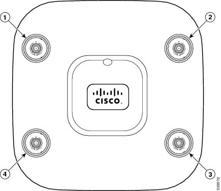
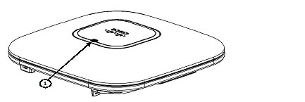
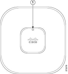
The 2602E model access points have external antenna connectors and the LED indictor on the top of the model, as shown in Figure 1. The 2602I model access points have integrated antennas and do not have external connectors on the top of the unit; however, they do have the LED indicator on top of the unit, as shown in Figure 2.
Figure 1 Access Point Ports and Connections (top)
|
1 |
Antenna connector A |
3 |
Antenna connector C |
|
2 |
Antenna connector B |
4 |
Antenna connector D |
Figure 2 Access Point LED Indicator (top)
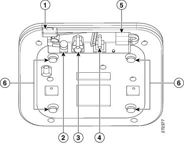
The ports and connections on the bottom of the access point are shown in Figure 3.
Figure 3 Access Point Ports and Connections (bottom)
|
1 |
Kensington lock slot |
4 |
Console port |
|
2 |
DC Power connection |
5 |
Security padlock and hasp (padlock not included) |
|
3 |
Gbit Ethernet port |
6 |
Mounting bracket pins (feet for desk or table-top mount) |
Configuring the Access Point
This section describes how to connect the access point to a wireless LAN controller. Because the configuration process takes place on the controller, see the Cisco Wireless LAN Controller Configuration Guide for additional information. This guide is available on Cisco.com.
The Controller Discovery Process
The access point uses standard Control and Provisioning of Wireless Access Points Protocol (CAPWAP) to communicate between the controller and other wireless access points on the network. CAPWAP is a standard, interoperable protocol which enables an access controller to manage a collection of wireless termination points. The discovery process using CAPWAP is identical to the Lightweight Access Point Protocol (LWAPP) used with previous Cisco Aironet access points. LWAPP-enabled access points are compatible with CAPWAP, and conversion to a CAPWAP controller is seamless. Deployments can combine CAPWAP and LWAPP software on the controllers.
The functionality provided by the controller does not change except for customers who have Layer 2 deployments, which CAPWAP does not support.
In a CAPWAP environment, a wireless access point discovers a controller by using CAPWAP discovery mechanisms and then sends it a CAPWAP join request. The controller sends the access point a CAPWAP join response allowing the access point to join the controller. When the access point joins the controller, the controller manages its configuration, firmware, control transactions, and data transactions.
Note![]() For additional information about the discovery process and CAPWAP, see the Cisco Wireless LAN Controller Software Configuration Guide. This document is available on Cisco.com.
For additional information about the discovery process and CAPWAP, see the Cisco Wireless LAN Controller Software Configuration Guide. This document is available on Cisco.com.
Note![]() CAPWAP support is provided in controller software release 5.2 or later. However, your controller must be running release 7.2.110.0 or later to support 2600 series access points.
CAPWAP support is provided in controller software release 5.2 or later. However, your controller must be running release 7.2.110.0 or later to support 2600 series access points.
Note![]() You cannot edit or query any access point using the controller CLI if the name of the access point contains a space.
You cannot edit or query any access point using the controller CLI if the name of the access point contains a space.
Note![]() Make sure that the controller is set to the current time. If the controller is set to a time that has already occurred, the access point might not join the controller because its certificate may not be valid for that time.
Make sure that the controller is set to the current time. If the controller is set to a time that has already occurred, the access point might not join the controller because its certificate may not be valid for that time.
Access points must be discovered by a controller before they can become an active part of the network. The access point supports these controller discovery processes:
- Layer 3 CAPWAP discovery—Can occur on different subnets than the access point and uses IP addresses and UDP packets rather than MAC addresses used by Layer 2 discovery.
- Over-the-air provisioning (OTAP)—This feature is supported by Cisco 4400 series controllers. If this feature is enabled on the controller, all joined access points transmit wireless CAPWAP neighbor messages, and new access points receive the controller IP address from these messages. This feature is disabled by default and should remain disabled when all access points are installed.
Additional information about OTAP is available on Cisco.com at the following link:
http://www.ciscosystems.com/en/US/products/ps6366/products_tech_note09186a008093d74a.shtml
- Locally stored controller IP address discovery—If the access point was previously joined to a controller, the IP addresses of the primary, secondary, and tertiary controllers are stored in the access point’s non-volatile memory. This process of storing controller IP addresses on an access point for later deployment is called priming the access point. For more information about priming, see the “Performing a Pre-Installation Configuration” section.
- DHCP server discovery—This feature uses DHCP option 43 to provide controller IP addresses to the access points. Cisco switches support a DHCP server option that is typically used for this capability. For more information about DHCP option 43, see the “Configuring DHCP Option 43 and DHCP Option 60” section.
- DNS discovery—The access point can discover controllers through your domain name server (DNS). For the access point to do so, you must configure your DNS to return controller IP addresses in response to CISCO-CAPWAP-CONTROLLER.localdomain, where localdomain is the access point domain name. Configuring the CISCO-CAPWAP-CONTROLLER provides backwards compatibility in an existing customer deployment. When an access point receives an IP address and DNS information from a DHCP server, it contacts the DNS to resolve CISCO-CAPWAP-CONTROLLER.localdomain. When the DNS sends a list of controller IP addresses, the access point sends discovery requests to the controllers.
Preparing the Access Point
Before you mount and deploy your access point, we recommend that you perform a site survey (or use the site planning tool) to determine the best location to install your access point.
You should have the following information about your wireless network available:
- Access point locations.
- Access point mounting options: below a suspended ceiling, on a flat horizontal surface, or on a desktop.
Note![]() You can mount the access point above a suspended ceiling but you must purchase additional mounting hardware: See “Mounting the Access Point” section for additional information.
You can mount the access point above a suspended ceiling but you must purchase additional mounting hardware: See “Mounting the Access Point” section for additional information.
- Access point power options: power supplied by the recommended external power supply (Cisco AIR-PWR-B), a DC power supply, PoE from a network device, or a PoE power injector/hub (usually located in a wiring closet).
Note![]() Access points mounted in a building’s environmental airspace must be powered using PoE to comply with safety regulations.
Access points mounted in a building’s environmental airspace must be powered using PoE to comply with safety regulations.
Cisco recommends that you make a site map showing access point locations so that you can record the device MAC addresses from each location and return them to the person who is planning or managing your wireless network.
Installation Summary
Installing the access point involves these operations:
- Performing a pre-installation configuration (optional)
- Mounting the access point
- Grounding the access point
- Deploying the access point on the wireless network
Performing a Pre-Installation Configuration
The following procedures ensure that your access point installation and initial operation go as expected. A pre-installation configuration is also known as priming the access point. This procedure is optional.
Note![]() Performing a pre-installation configuration is an optional procedure. If your network controller is properly configured, you can install your access point in its final location and connect it to the network from there. See the “Deploying the Access Point on the Wireless Network” section for details.
Performing a pre-installation configuration is an optional procedure. If your network controller is properly configured, you can install your access point in its final location and connect it to the network from there. See the “Deploying the Access Point on the Wireless Network” section for details.
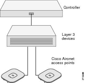
Pre-Installation Configuration Setup
The pre-installation configuration setup is shown in Figure 4.
Figure 4 Pre-Installation Configuration Setup
To perform pre-installation configuration, perform the following steps:
Step 1![]() Make sure that the Cisco wireless LAN controller DS port is connected to the network. Use the CLI, web-browser interface, or Cisco WCS procedures as described in the appropriate Cisco wireless LAN controller guide.
Make sure that the Cisco wireless LAN controller DS port is connected to the network. Use the CLI, web-browser interface, or Cisco WCS procedures as described in the appropriate Cisco wireless LAN controller guide.
a.![]() Make sure that access points have Layer 3 connectivity to the Cisco wireless LAN controller Management and AP-Manager Interface.
Make sure that access points have Layer 3 connectivity to the Cisco wireless LAN controller Management and AP-Manager Interface.
b.![]() Configure the switch to which your access point is to attach. See the Cisco Unified Wireless Network WLAN Controller Guide: Cisco 440x Series WLAN Controllers for additional information.
Configure the switch to which your access point is to attach. See the Cisco Unified Wireless Network WLAN Controller Guide: Cisco 440x Series WLAN Controllers for additional information.
c.![]() Set the Cisco wireless LAN controller as the master so that new access points always join with it.
Set the Cisco wireless LAN controller as the master so that new access points always join with it.
d.![]() Make sure DHCP is enabled on the network. The access point must receive its IP address through DHCP.
Make sure DHCP is enabled on the network. The access point must receive its IP address through DHCP.
e.![]() CAPWAP UDP ports must not be blocked in the network.
CAPWAP UDP ports must not be blocked in the network.
f.![]() The access point must be able to find the IP address of the controller. This can be accomplished using DHCP, DNS, or IP subnet broadcast. This guide describes the DHCP method to convey the controller IP address. For other methods, refer to the product documentation. See also the “Using DHCP Option 43” section for more information.
The access point must be able to find the IP address of the controller. This can be accomplished using DHCP, DNS, or IP subnet broadcast. This guide describes the DHCP method to convey the controller IP address. For other methods, refer to the product documentation. See also the “Using DHCP Option 43” section for more information.
Step 2![]() Apply power to the access point:
Apply power to the access point:
a.![]() The access point is 802.3af (15.4 W) compliant and can be powered by any of the following 802.3af compliant devices:
The access point is 802.3af (15.4 W) compliant and can be powered by any of the following 802.3af compliant devices:
–![]() WS-C3550, WS-C3560, and WS-C3750 switches
WS-C3550, WS-C3560, and WS-C3750 switches
–![]() C1880 switch
C1880 switch
–![]() 2600, 2610, 2611, 2621, 2650, and 2651 multiservice platforms
2600, 2610, 2611, 2621, 2650, and 2651 multiservice platforms
–![]() 2610XM, 2611XM, 2621XM, 2650XM, 2651XM, and 2691 multiservice platforms
2610XM, 2611XM, 2621XM, 2650XM, 2651XM, and 2691 multiservice platforms
–![]() 2811, 2821, and 2851 integrated services routers
2811, 2821, and 2851 integrated services routers
–![]() 3620, 3631-telco, 3640, and 3660 multiservice platforms
3620, 3631-telco, 3640, and 3660 multiservice platforms
–![]() 3725 and 3745 multiservice access routers
3725 and 3745 multiservice access routers
–![]() 3825 and 3845 integrated services routers
3825 and 3845 integrated services routers
The recommended external power supply for the access point is the Cisco AIR-PWR-B power supply. The access point can also be powered by the following optional external power sources:
–![]() 1250 series access point power injector (AIR-PWRINJ4)
1250 series access point power injector (AIR-PWRINJ4)
–![]() Any 802.3af compliant power injector
Any 802.3af compliant power injector
Note![]() The 2600 series access point requires a Gigibit Ethernet link to prevent the Ethernet port from becoming a bottleneck for traffic because wireless traffic speeds exceed transmit speeds of a 10/100 Ethernet port.
The 2600 series access point requires a Gigibit Ethernet link to prevent the Ethernet port from becoming a bottleneck for traffic because wireless traffic speeds exceed transmit speeds of a 10/100 Ethernet port.
b.![]() As the access point attempts to connect to the controller, the LEDs cycle through a green, red, and amber sequence, which can take up to 5 minutes.
As the access point attempts to connect to the controller, the LEDs cycle through a green, red, and amber sequence, which can take up to 5 minutes.
Note![]() If the access point remains in this mode for more than five minutes, the access point is unable to find the Master Cisco wireless LAN controller. Check the connection between the access point and the Cisco wireless LAN controller and be sure that they are on the same subnet.
If the access point remains in this mode for more than five minutes, the access point is unable to find the Master Cisco wireless LAN controller. Check the connection between the access point and the Cisco wireless LAN controller and be sure that they are on the same subnet.
c.![]() If the access point shuts down, check the power source.
If the access point shuts down, check the power source.
d.![]() After the access point finds the Cisco wireless LAN controller, it attempts to download the new operating system code if the access point code version differs from the Cisco wireless LAN controller code version. While this is happening, the Status LED blinks dark blue.
After the access point finds the Cisco wireless LAN controller, it attempts to download the new operating system code if the access point code version differs from the Cisco wireless LAN controller code version. While this is happening, the Status LED blinks dark blue.
e.![]() If the operating system download is successful, the access point reboots.
If the operating system download is successful, the access point reboots.
Step 3![]() Configure the access point if required. Use the controller CLI, controller GUI, or Cisco WCS to customize the access-point-specific 802.11n network settings.
Configure the access point if required. Use the controller CLI, controller GUI, or Cisco WCS to customize the access-point-specific 802.11n network settings.
Step 4![]() If the pre-installation configuration is successful, the Status LED is green indicating normal operation. Disconnect the access point and mount it at the location at which you intend to deploy it on the wireless network.
If the pre-installation configuration is successful, the Status LED is green indicating normal operation. Disconnect the access point and mount it at the location at which you intend to deploy it on the wireless network.
Step 5![]() If your access point does not indicate normal operation, turn it off and repeat the pre-installation configuration.
If your access point does not indicate normal operation, turn it off and repeat the pre-installation configuration.
Note![]() When you are installing a Layer 3 access point on a different subnet than the Cisco wireless LAN controller, be sure that a DHCP server is reachable from the subnet on which you will be installing the access point, and that the subnet has a route back to the Cisco wireless LAN controller. Also be sure that the route back to the Cisco wireless LAN controller has destination UDP ports 5246 and 5247 open for CAPWAP communications. Ensure that the route back to the primary, secondary, and tertiary wireless LAN controller allows IP packet fragments. Finally, be sure that if address translation is used, that the access point and the Cisco wireless LAN controller have a static 1-to-1 NAT to an outside address. (Port Address Translation is not supported.)
When you are installing a Layer 3 access point on a different subnet than the Cisco wireless LAN controller, be sure that a DHCP server is reachable from the subnet on which you will be installing the access point, and that the subnet has a route back to the Cisco wireless LAN controller. Also be sure that the route back to the Cisco wireless LAN controller has destination UDP ports 5246 and 5247 open for CAPWAP communications. Ensure that the route back to the primary, secondary, and tertiary wireless LAN controller allows IP packet fragments. Finally, be sure that if address translation is used, that the access point and the Cisco wireless LAN controller have a static 1-to-1 NAT to an outside address. (Port Address Translation is not supported.)
Deploying the Access Point on the Wireless Network
After you have mounted the access point, follow these steps to deploy it on the wireless network:
Step 1![]() Connect and power up the access point.
Connect and power up the access point.
Step 2![]() Observe the access point LED (for LED descriptions, see “Checking the Access Point LED” section).
Observe the access point LED (for LED descriptions, see “Checking the Access Point LED” section).
a.![]() When you power up the access point, it begins a power-up sequence that you can verify by observing the access point LED. If the power-up sequence is successful, the discovery and join process begins. During this process, the LED blinks sequentially green, red, and off. When the access point has joined a controller, the LED is green if no clients are associated or blue if one or more clients are associated.
When you power up the access point, it begins a power-up sequence that you can verify by observing the access point LED. If the power-up sequence is successful, the discovery and join process begins. During this process, the LED blinks sequentially green, red, and off. When the access point has joined a controller, the LED is green if no clients are associated or blue if one or more clients are associated.
b.![]() If the LED is not on, the access point is most likely not receiving power.
If the LED is not on, the access point is most likely not receiving power.
c.![]() If the LED blinks sequentially for more than 5 minutes, the access point is unable to find its primary, secondary, and tertiary Cisco wireless LAN controller. Check the connection between the access point and the Cisco wireless LAN controller, and be sure the access point and the Cisco wireless LAN controller are either on the same subnet or that the access point has a route back to its primary, secondary, and tertiary Cisco wireless LAN controller. Also, if the access point is not on the same subnet as the Cisco wireless LAN controller, be sure that there is a properly configured DHCP server on the same subnet as the access point. See the “Configuring DHCP Option 43 and DHCP Option 60” section for additional information.
If the LED blinks sequentially for more than 5 minutes, the access point is unable to find its primary, secondary, and tertiary Cisco wireless LAN controller. Check the connection between the access point and the Cisco wireless LAN controller, and be sure the access point and the Cisco wireless LAN controller are either on the same subnet or that the access point has a route back to its primary, secondary, and tertiary Cisco wireless LAN controller. Also, if the access point is not on the same subnet as the Cisco wireless LAN controller, be sure that there is a properly configured DHCP server on the same subnet as the access point. See the “Configuring DHCP Option 43 and DHCP Option 60” section for additional information.
Step 3![]() Reconfigure the Cisco wireless LAN controller so that it is not the Master.
Reconfigure the Cisco wireless LAN controller so that it is not the Master.
Note![]() A Master Cisco wireless LAN controller should be used only for configuring access points and not in a working network.
A Master Cisco wireless LAN controller should be used only for configuring access points and not in a working network.
Troubleshooting
If you experience difficulty getting your access point installed and running, look for a solution to your problem in this guide or in additional access point documentation. These, and other documents, are available on Cisco.com.
Guidelines for Using Cisco Aironet Lightweight Access Points
Keep these guidelines in mind when you use 2600 series lightweight access points:
- The access point can only communicate with Cisco wireless LAN controllers, such as 2500 series, 5500 series, and WiSM controllers.
- The access point does not support Wireless Domain Services (WDS) and cannot communicate with WDS devices. However, the controller provides functionality equivalent to WDS when the access point joins it.
- CAPWAP does not support Layer 2. The access point must get an IP address and discover the controller using Layer 3, DHCP, DNS, or IP subnet broadcast.
- The access point console port is enabled for monitoring and debug purposes. All configuration commands are disabled when the access point is connected to a controller.
Checking the Access Point LED
The location of the access point status LED is shown in Figure 5.
Note![]() Regarding LED status colors, it is expected that there will be small variations in color intensity and hue from unit to unit. This is within the normal range of the LED manufacturer’s specifications and is not a defect.
Regarding LED status colors, it is expected that there will be small variations in color intensity and hue from unit to unit. This is within the normal range of the LED manufacturer’s specifications and is not a defect.
Figure 5 Access Point LED Location
The access point status LED indicates various conditions and are described in Table 1.
|
Message |
Status |
Message Meaning |
|---|---|---|
|
Boot loader status sequence |
Blinking green |
DRAM memory test in progress |
|
DRAM memory test OK |
||
|
Board initialization in progress |
||
|
Initializing FLASH file system |
||
|
FLASH memory test OK |
||
|
Initializing Ethernet |
||
|
Ethernet OK |
||
|
Starting Cisco IOS |
||
|
Initialization successful |
||
|
Association status |
Green |
Normal operating condition, but no wireless client associated |
|
Blue |
Normal operating condition, at least one wireless client association |
|
|
Operating status |
Blinking blue |
Software upgrade in progress |
|
Cycling through green, red, and off |
Discovery/join process in progress |
|
|
Rapidly cycling through blue, green, and red |
Access point location command invoked |
|
|
Blinking red |
Ethernet link not operational |
|
|
Boot loader warnings |
Blinking blue |
Configuration recovery in progress (MODE button pushed for 2 to 3 seconds) |
|
Red |
Ethernet failure or image recovery (MODE button pushed for 20 to 30 seconds) |
|
|
Blinking green |
Image recovery in progress (MODE button released) |
|
|
Boot loader errors |
Red |
DRAM memory test failure |
|
Blinking red and blue |
FLASH file system failure |
|
|
Blinking red and off |
Environment variable failure |
|
|
Bad MAC address |
||
|
Ethernet failure during image recovery |
||
|
Boot environment failure |
||
|
No Cisco image file |
||
|
Boot failure |
||
|
Cisco IOS errors |
Red |
Software failure; try disconnecting and reconnecting unit power |
|
Cycling through blue, green, red, and off |
General warning; insufficient inline power |
Troubleshooting the Access Point Join Process
Access points can fail to join a controller for many reasons: a RADIUS authorization is pending; self-signed certificates are not enabled on the controller; the access point’s and controller’s regulatory domains don’t match, and so on.
Controller software enables you to configure the access points to send all CAPWAP-related errors to a syslog server. You do not need to enable any debug commands on the controller because all of the CAPWAP error messages can be viewed from the syslog server itself.
The state of the access point is not maintained on the controller until it receives a CAPWAP join request from the access point. Therefore, it can be difficult to determine why the CAPWAP discovery request from a certain access point was rejected. In order to troubleshoot such joining problems without enabling CAPWAP debug commands on the controller, the controller collects information for all access points that send a discovery message to it and maintains information for any access points that have successfully joined it.
The controller collects all join-related information for each access point that sends a CAPWAP discovery request to the controller. Collection begins with the first discovery message received from the access point and ends with the last configuration payload sent from the controller to the access point.
You can view join-related information for the following numbers of access points:
- Up to 300 access points for 4400 series controllers, the Cisco WiSM, and the Catalyst 3750G Integrated Wireless LAN Controller Switch
- Up to three times the maximum number of access points supported by the platform for the 2600 series controllers and the Controller Network Module within the Cisco 28/37/38xx Series Integrated Services Routers
When the controller is maintaining join-related information for the maximum number of access points, it does not collect information for any more access points.
An access point sends all syslog messages to IP address 255.255.255.255 by default when any of the following conditions are met:
- An access point running software release 5.2 or later has been newly deployed.
- An existing access point running software release 5.2 or later has been reset after clearing the configuration.
If any of these conditions are met and the access point has not yet joined a controller, you can also configure a DHCP server to return a syslog server IP address to the access point using option 7 on the server. The access point then starts sending all syslog messages to this IP address.
When the access point joins a controller for the first time, the controller sends the global syslog server IP address (the default is 255.255.255.255) to the access point. After that, the access point sends all syslog messages to this IP address until it is overridden by one of the following scenarios:
- The access point is still connected to the same controller, and the global syslog server IP address configuration on the controller has been changed using the config ap syslog host global syslog_server_IP_address command. In this case, the controller sends the new global syslog server IP address to the access point.
- The access point is still connected to the same controller, and a specific syslog server IP address has been configured for the access point on the controller using the config ap syslog host specific Cisco_AP syslog_server_IP_address command. In this case, the controller sends the new specific syslog server IP address to the access point.
- The access point is disconnected from the controller and joins another controller. In this case, the new controller sends its global syslog server IP address to the access point.
- Whenever a new syslog server IP address overrides the existing syslog server IP address, the old address is erased from persistent storage, and the new address is stored in its place. The access point also starts sending all syslog messages to the new IP address provided the access point can reach the syslog server IP address.
You can configure the syslog server for access points and view the access point join information only from the controller CLI.
A detailed explanation of the join process is on Cisco.com at the following URL:
http://www.Cisco.com/en/US/products/ps6366/products_tech_note09186a00808f8599.shtml
Declarations of Conformity and Regulatory Information
This section provides declarations of conformity and regulatory information for Cisco Aironet 2600 Series Access Points. You can find additional information at this URL:
www.cisco.com/go/aironet/compliance
Manufacturers Federal Communication Commission Declaration of Conformity Statement

|
Models |
Certification Numbers |
|---|---|
|
AIR-CAP2602E-A-K9 AIR-CAP2602E-B-K9 |
LDK102080 |
Manufacturer:
Cisco Systems, Inc.
170 West Tasman Drive
San Jose, CA 95134-1706
USA
This device complies with Part 15 rules. Operation is subject to the following two conditions:
1.![]() This device may not cause harmful interference, and
This device may not cause harmful interference, and
2.![]() This device must accept any interference received, including interference that may cause undesired operation.
This device must accept any interference received, including interference that may cause undesired operation.
This device operates in the 5150-5250MHz and 5470-5725MHz bands and is therefore restricted to indoor operation only per FCC guidance.
This equipment has been tested and found to comply with the limits of a Class B digital device, pursuant to Part 15 of the FCC Rules. These limits are designed to provide reasonable protection against harmful interference when the equipment is operated in a residential environment. This equipment generates, uses, and radiates radio frequency energy, and if not installed and used in accordance with the instructions, may cause harmful interference. However, there is no guarantee that interference will not occur. If this equipment does cause interference to radio or television reception, which can be determined by turning the equipment off and on, the user is encouraged to correct the interference by one of the following measures:
- Reorient or relocate the receiving antenna.
- Increase separation between the equipment and receiver.
- Connect the equipment to an outlet on a circuit different from which the receiver is connected.
- Consult the dealer or an experienced radio/TV technician.
Caution
![]() The Part 15 radio device operates on a non-interference basis with other devices operating at this frequency when using the integrated antennas. Any changes or modification to the product not expressly approved by Cisco could void the user’s authority to operate this device.
The Part 15 radio device operates on a non-interference basis with other devices operating at this frequency when using the integrated antennas. Any changes or modification to the product not expressly approved by Cisco could void the user’s authority to operate this device.
Caution
![]() Within the 5.15 to 5.25 GHz and 5.47-5.725 GHz bands, this device is restricted to indoor operations to reduce any potential for harmful interference to co-channel Mobile Satellite System (MSS) operations.
Within the 5.15 to 5.25 GHz and 5.47-5.725 GHz bands, this device is restricted to indoor operations to reduce any potential for harmful interference to co-channel Mobile Satellite System (MSS) operations.
VCCI Statement for Japan
|
Warning |
This is a Class B product based on the standard of the Voluntary Control Council for Interference from Information Technology Equipment (VCCI). If this is used near a radio or television receiver in a domestic environment, it may cause radio interference. Install and use the equipment according to the instruction manual. |
|
|
|


Guidelines for Operating Cisco Aironet Access Points in Japan
This section provides guidelines for avoiding interference when operating Cisco Aironet access points in Japan. These guidelines are provided in both Japanese and English.
Japanese Translation
English Translation
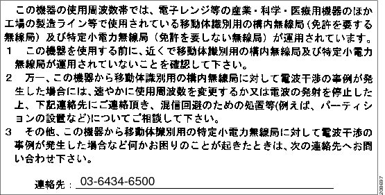
This equipment operates in the same frequency bandwidth as industrial, scientific, and medical devices such as microwave ovens and mobile object identification (RF-ID) systems (licensed premises radio stations and unlicensed specified low-power radio stations) used in factory production lines.
1.![]() Before using this equipment, make sure that no premises radio stations or specified low-power radio stations of RF-ID are used in the vicinity.
Before using this equipment, make sure that no premises radio stations or specified low-power radio stations of RF-ID are used in the vicinity.
2.![]() If this equipment causes RF interference to a premises radio station of RF-ID, promptly change the frequency or stop using the device; contact the number below and ask for recommendations on avoiding radio interference, such as setting partitions.
If this equipment causes RF interference to a premises radio station of RF-ID, promptly change the frequency or stop using the device; contact the number below and ask for recommendations on avoiding radio interference, such as setting partitions.
3.![]() If this equipment causes RF interference to a specified low-power radio station of RF-ID, contact the number below.
If this equipment causes RF interference to a specified low-power radio station of RF-ID, contact the number below.
Contact Number: 03-6434-6500
Statement 371—Power Cable and AC Adapter

English Translation
When installing the product, please use the provided or designated connection cables/power cables/AC adaptors. Using any other cables/adaptors could cause a malfunction or a fire. Electrical Appliance and Material Safety Law prohibits the use of UL-certified cables (that have the “UL” shown on the code) for any other electrical devices than products designated by CISCO. The use of cables that are certified by Electrical Appliance and Material Safety Law (that have “PSE” shown on the code) is not limited to CISCO-designated products.
Industry Canada
Canadian Compliance Statement
|
Models |
Certification Numbers |
|---|---|
|
AIR-CAP2602E-A-K9 |
2461B-102080 |
This Class B Digital apparatus meets all the requirements of the Canadian Interference-Causing Equipment Regulations.
Cet appareil numerique de la classe B respecte les exigences du Reglement sur le material broilleur du Canada.
This device complies with Class B Limits of Industry Canada. Operation is subject to the following two conditions:
1.![]() This device may not cause harmful interference, and
This device may not cause harmful interference, and
2.![]() This device must accept any interference received, including interference that may cause undesired operation.
This device must accept any interference received, including interference that may cause undesired operation.
Cisco Aironet Access Points are certified to the requirements of RSS-210. The use of this device in a system operating either partially or completely outdoors may require the user to obtain a license for the system according to the Canadian regulations. For further information, contact your local Industry Canada office.
This device has been designed to operate with antennas having a maximum gain of 6 dBi. Antennas having a gain greater than 6 dBi are strictly prohibited for use with this device. The required antenna impedance is 50 ohms.
To reduce potential radio interference to other users, the antenna type and its gain should be so chosen that the equivalent isotropically radiated power (EIRP) is not more than that permitted for successful communication.
European Community, Switzerland, Norway, Iceland, and Liechtenstein
Models:
AIR-CAP2602E-E-K9
AIR-CAP2602I-E-K9
AIR-SAP2602E-E-K9
AIR-SAP2602I-E-K9
Declaration of Conformity with regard to the R&TTE Directive 1999/5/EC & Medical Directive 93/42/EEC
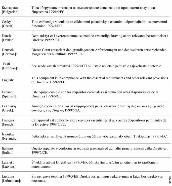

The following standards were applied:
EMC—EN 301.489-1 v1.8.1; EN 301.489-17 v2.1.1
Health & Safety—EN60950-1: 2005; EN 50385: 2002
Radio—EN 300 328 v 1.7.1; EN 301.893 v 1.5.1
The conformity assessment procedure referred to in Article 10.4 and Annex III of Directive 1999/5/EC has been followed.
This device also conforms to the EMC requirements of the Medical Devices Directive 93/42/EEC.
Note![]() This equipment is intended to be used in all EU and EFTA countries. Outdoor use may be restricted to certain frequencies and/or may require a license for operation. For more details, contact Cisco Corporate Compliance.
This equipment is intended to be used in all EU and EFTA countries. Outdoor use may be restricted to certain frequencies and/or may require a license for operation. For more details, contact Cisco Corporate Compliance.
The product carries the CE Mark:

Declaration of Conformity for RF Exposure
This section contains information on compliance with guidelines related to RF exposure.
Generic Discussion on RF Exposure
The Cisco products are designed to comply with the following national and international standards on Human Exposure to Radio Frequencies:
- US 47 Code of Federal Regulations Part 2 Subpart J
- American National Standards Institute (ANSI) / Institute of Electrical and Electronic Engineers / IEEE C 95.1 (99)
- International Commission on Non Ionizing Radiation Protection (ICNIRP) 98
- Ministry of Health (Canada) Safety Code 6. Limits on Human Exposure to Radio Frequency Fields in the range from 3kHz to 300 GHz
- Australia Radiation Protection Standard
To ensure compliance with various national and international Electromagnetic Field (EMF) standards, the system should only be operated with Cisco approved antennas and accessories.
This Device Meets International Guidelines for Exposure to Radio Waves
The 2600 series device includes a radio transmitter and receiver. It is designed not to exceed the limits for exposure to radio waves (radio frequency electromagnetic fields) recommended by international guidelines. The guidelines were developed by an independent scientific organization (ICNIRP) and include a substantial safety margin designed to ensure the safety of all persons, regardless of age and health.
As such the systems are designed to be operated as to avoid contact with the antennas by the end user. It is recommended to set the system in a location where the antennas can remain at least a minimum distance as specified from the user in accordance to the regulatory guidelines which are designed to reduce the overall exposure of the user or operator.
|
Separation Distance |
||
|---|---|---|
|
MPE |
Distance |
Limit |
|
0.63 mW/cm2 |
20 cm (7.87 inches) |
1.00 mW/cm2 |
The World Health Organization has stated that present scientific information does not indicate the need for any special precautions for the use of wireless devices. They recommend that if you are interested in further reducing your exposure then you can easily do so by reorienting antennas away from the user or placing he antennas at a greater separation distance then recommended.
This Device Meets FCC Guidelines for Exposure to Radio Waves
The 2600 series device includes a radio transmitter and receiver. It is designed not to exceed the limits for exposure to radio waves (radio frequency electromagnetic fields) as referenced in FCC Part 1.1310. The guidelines are based on IEEE ANSI C 95.1 (92) and include a substantial safety margin designed to ensure the safety of all persons, regardless of age and health.
As such the systems are designed to be operated as to avoid contact with the antennas by the end user. It is recommended to set the system in a location where the antennas can remain at least a minimum distance as specified from the user in accordance to the regulatory guidelines which are designed to reduce the overall exposure of the user or operator.
The device has been tested and found compliant with the applicable regulations as part of the radio certification process.
|
Separation Distance |
||
|---|---|---|
|
MPE |
Distance |
Limit |
|
0.63 mW/cm2 |
20 cm (7.87 inches) |
1.00 mW/cm2 |
The US Food and Drug Administration has stated that present scientific information does not indicate the need for any special precautions for the use of wireless devices. The FCC recommends that if you are interested in further reducing your exposure then you can easily do so by reorienting antennas away from the user or placing the antennas at a greater separation distance then recommended or lowering the transmitter power output.
This Device Meets the Industry Canada Guidelines for Exposure to Radio Waves
The 2600 series device includes a radio transmitter and receiver. It is designed not to exceed the limits for exposure to radio waves (radio frequency electromagnetic fields) as referenced in Health Canada Safety Code 6. The guidelines include a substantial safety margin designed into the limit to ensure the safety of all persons, regardless of age and health.
As such the systems are designed to be operated as to avoid contact with the antennas by the end user. It is recommended to set the system in a location where the antennas can remain at least a minimum distance as specified from the user in accordance to the regulatory guidelines which are designed to reduce the overall exposure of the user or operator.
|
Separation Distance |
||
|---|---|---|
|
MPE |
Distance |
Limit |
|
0.63 mW/cm2 |
20 cm (7.87 inches) |
1.00 mW/cm2 |
Health Canada states that present scientific information does not indicate the need for any special precautions for the use of wireless devices. They recommend that if you are interested in further reducing your exposure you can easily do so by reorienting antennas away from the user, placing the antennas at a greater separation distance than recommended, or lowering the transmitter power output.
Cet appareil est conforme aux directives internationales en matière d’exposition aux fréquences radioélectriques
Cet appareil de la gamme 1700 comprend un émetteur-récepteur radio. Il a été conçu de manière à respecter les limites en matière d’exposition aux fréquences radioélectriques (champs électromagnétiques de fréquence radio), recommandées dans le code de sécurité 6 de Santé Canada. Ces directives intègrent une marge de sécurité importante destinée à assurer la sécurité de tous, indépendamment de l’âge et de la santé.
Par conséquent, les systèmes sont conçus pour être exploités en évitant que l’utilisateur n’entre en contact avec les antennes. Il est recommandé de poser le système là où les antennes sont à une distance minimale telle que précisée par l’utilisateur conformément aux directives réglementaires qui sont conçues pour réduire l’exposition générale de l’utilisateur ou de l’opérateur.
|
Distance d’éloignement |
||
|---|---|---|
|
MPE |
Distance |
Limite |
|
0.63 mW/cm2 |
20 cm (7.87 po) |
1.00 mW/cm2 |
Santé Canada affirme que la littérature scientifique actuelle n’indique pas qu’il faille prendre des précautions particulières lors de l’utilisation d’un appareil sans fil. Si vous voulez réduire votre exposition encore davantage, selon l’agence, vous pouvez facilement le faire en réorientant les antennes afin qu’elles soient dirigées à l’écart de l’utilisateur, en les plaçant à une distance d’éloignement supérieure à celle recommandée ou en réduisant la puissance de sortie de l’émetteur.
Additional Information on RF Exposure
You can find additional information on the subject at the following links:
- Cisco Systems Spread Spectrum Radios and RF Safety white paper at this URL:
http://www.cisco.com/warp/public/cc/pd/witc/ao340ap/prodlit/rfhr_wi.htm - FCC Bulletin 56: Questions and Answers about Biological Effects and Potential Hazards of Radio Frequency Electromagnetic Fields
- FCC Bulletin 65: Evaluating Compliance with the FCC guidelines for Human Exposure to Radio Frequency Electromagnetic Fields
- FCC Bulletin 65C (01-01): Evaluating Compliance with the FCC guidelines for Human Exposure to Radio Frequency Electromagnetic Fields: Additional Information for Evaluating Compliance for Mobile and Portable Devices with FCC limits for Human Exposure to Radio Frequency Emission
You can obtain additional information from the following organizations:
- World Health Organization Internal Commission on Non-Ionizing Radiation Protection at this URL: www.who.int/emf
- United Kingdom, National Radiological Protection Board at this URL: www.nrpb.org.uk
- Cellular Telecommunications Association at this URL: www.wow-com.com
- The Mobile Manufacturers Forum at this URL: www.mmfai.org
Administrative Rules for Cisco Aironet Access Points in Taiwan
This section provides administrative rules for operating Cisco Aironet access points in Taiwan. The rules for all access points are provided in both Chinese and English.
Chinese Translation
English Translation
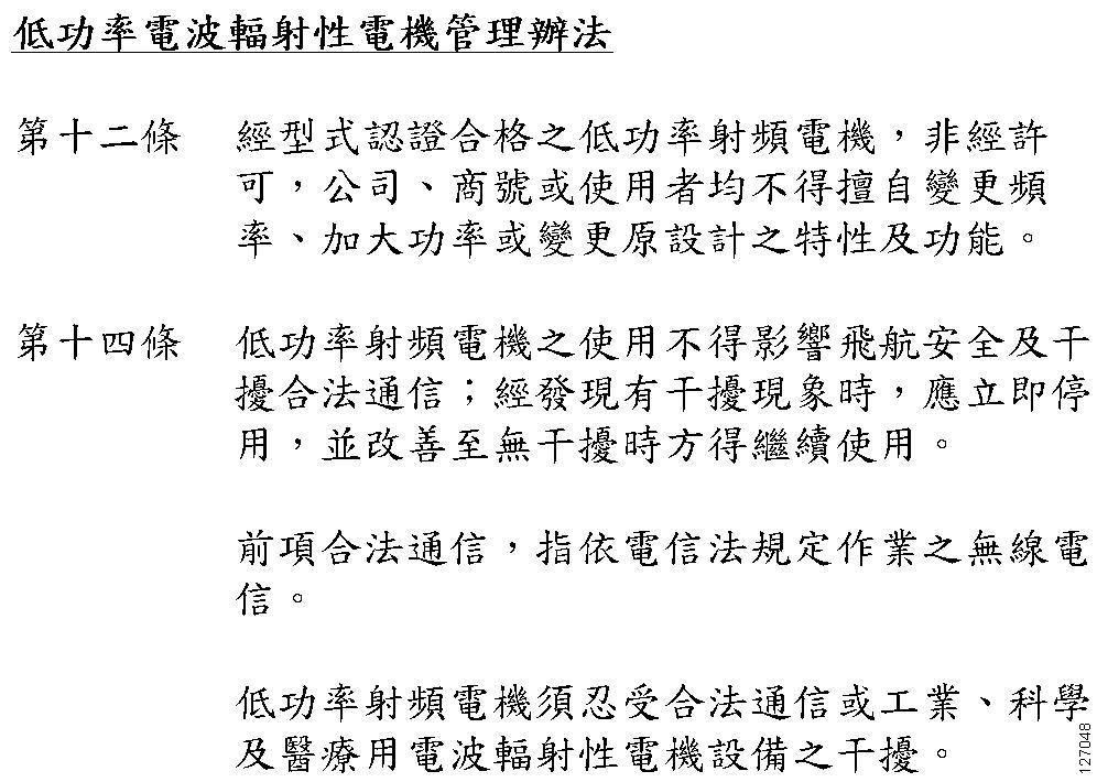
Administrative Rules for Low-power Radio-Frequency Devices
Article 12
For those low-power radio-frequency devices that have already received a type-approval, companies, business units or users should not change its frequencies, increase its power or change its original features and functions.
Article 14
The operation of the low-power radio-frequency devices is subject to the conditions that no harmful interference is caused to aviation safety and authorized radio station; and if interference is caused, the user must stop operating the device immediately and can’t re-operate it until the harmful interference is clear.
The authorized radio station means a radio-communication service operating in accordance with the Communication Act.
The operation of the low-power radio-frequency devices is subject to the interference caused by the operation of an authorized radio station, by another intentional or unintentional radiator, by industrial, scientific and medical (ISM) equipment, or by an incidental radiator.
Chinese Translation
English Translation
Low-power Radio-frequency Devices Technical Specifications
|
4.7 |
Unlicensed National Information Infrastructure |
|
4.7.5 |
Within the 5.25-5.35 GHz band, U-NII devices will be restricted to indoor operations to reduce any potential for harmful interference to co-channel MSS operations. |
|
4.7.6 |
The U-NII devices shall accept any interference from legal communications and shall not interfere the legal communications. If interference is caused, the user must stop operating the device immediately and can’t re-operate it until the harmful interference is clear. |
|
4.7.7 |
Manufacturers of U-NII devices are responsible for ensuring frequency stability such that an emission is maintained within the band of operation under all conditions of normal operation as specified in the user manual. |
Operation of Cisco Aironet Access Points in Brazil
This section contains special information for operation of Cisco Aironet access points in Brazil.
Access Point Models
AIR-CAP2602E-T-K9
AIR-CAP2602I-T-K9
AIR-SAP2602E-T-K9
AIR-SAP2602I-T-K9
Regulatory Information
Figure 6 contains Brazil regulatory information for the access point models identified in the previous section.
Figure 6 Brazil Regulatory Information

Portuguese Translation
Este equipamento opera em caráter secundário, isto é, não tem direito a proteção contra interferência prejudicial, mesmo de estações do mesmo tipo, e não pode causar interferência a sistemas operando em caráter primário.
English Translation
This equipment operates on a secondary basis and consequently must accept harmful interference, including interference from stations of the same kind. This equipment may not cause harmful interference to systems operating on a primary basis.
Declaration of Conformity Statements
All the Declaration of Conformity statements related to this product can be found at the following location: http://www.ciscofax.com
Configuring DHCP Option 43 and DHCP Option 60
This section contains a DHCP Option 43 configuration example on a Windows 2003 Enterprise DHCP server for use with Cisco Aironet lightweight access points. For other DHCP server implementations, consult product documentation for configuring DHCP Option 43. In Option 43, you should use the IP address of the controller management interface.
Note![]() DHCP Option 43 is limited to one access point type per DHCP pool. You must configure a separate DHCP pool for each access point type.
DHCP Option 43 is limited to one access point type per DHCP pool. You must configure a separate DHCP pool for each access point type.
The 2600 series access point uses the type-length-value (TLV) format for DHCP Option 43. DHCP servers must be programmed to return the option based on the access point’s DHCP Vendor Class Identifier (VCI) string (DHCP Option 60). The VCI string for the 2600 series access point is:
Cisco AP c2600
Note![]() If your access point was ordered with the Service Provider Option (AIR-OPT60-DHCP) selected in the ordering tool, the VCI string for the access point contains ServiceProvider. For example, a 2600 with this option will return this VCI string:
If your access point was ordered with the Service Provider Option (AIR-OPT60-DHCP) selected in the ordering tool, the VCI string for the access point contains ServiceProvider. For example, a 2600 with this option will return this VCI string:
Cisco AP c2600-ServiceProvider
The format of the TLV block is listed below:
- Type: 0xf1 (decimal 241)
- Length: Number of controller IP addresses * 4
- Value: List of WLC management interfaces
To configure DHCP Option 43 in the embedded Cisco IOS DHCP server, follow these steps:
Step 1![]() Enter configuration mode at the Cisco IOS CLI.
Enter configuration mode at the Cisco IOS CLI.
Step 2![]() Create the DHCP pool, including the necessary parameters such as default router and name server. A DHCP scope example is as follows:
Create the DHCP pool, including the necessary parameters such as default router and name server. A DHCP scope example is as follows:
ip dhcp pool <pool name>
network <IP Network> <Netmask>
default-router <Default router>
dns-server <DNS Server>
Where:
<pool name> is the name of the DHCP pool, such as AP2602
<IP Network> is the network IP address where the controller resides, such as 10.0.15.1
<Netmask> is the subnet mask, such as 255.255.255.0
<Default router> is the IP address of the default router, such as 10.0.0.1
<DNS Server> is the IP address of the DNS server, such as 10.0.10.2
Step 3![]() Add the option 60 line using the following syntax:
Add the option 60 line using the following syntax:
option 60 ascii “VCI string”
For the VCI string, “Cisco AP c2600”, the quotation marks must be included.
Step 4![]() Add the option 43 line using the following syntax:
Add the option 43 line using the following syntax:
option 43 hex <hex string>
The hex string is assembled by concatenating the TLV values shown below:
Type + Length + Value
Type is always f1(hex). Length is the number of controller management IP addresses times 4 in hex. Value is the IP address of the controller listed sequentially in hex.
For example, suppose that there are two controllers with management interface IP addresses, 10.126.126.2 and 10.127.127.2. The type is f1(hex). The length is 2 * 4 = 8 = 08 (hex). The IP addresses translate to 0a7e7e02 and 0a7f7f02. Assembling the string then yields f1080a7e7e020a7f7f02. The resulting Cisco IOS command added to the DHCP scope is option 43 hex f1080a7e7e020a7f7f02.
Obtaining Documentation and Submitting a Service Request
For information on obtaining documentation, submitting a service request, and gathering additional information, see the monthly What’s New in Cisco Product Documentation, which also lists all new and revised Cisco technical documentation, at:
http://www.cisco.com/c/en/us/td/docs/general/whatsnew/whatsnew.html
Subscribe to the What’s New in Cisco Product Documentation as an RSS feed and set content to be delivered directly to your desktop using a reader application. The RSS feeds are a free service. Cisco currently supports RSS Version 2.0.

Text Part Number:
78-10809-01
Release Notes for Cisco IOS
Release 12.0(7)XK1 Feature Packs
for Cisco 2600 Series Routers
March 20, 2000
These release notes describe Cisco IOS Release 12.0(7)XK1 feature packs for Cisco 2600 series
routers. Use them with the documents listed in the “Related Documentation” section on page 23.
These release notes describe the following topics:
• How to Use These Release Notes, page 2
• What Is a Feature Pack?, page 2
• Memory Options, page 3
• Routers and Interfaces Supported, page 3
Corporate Headquarters
Cisco Systems, Inc.
170 West Tasman Drive
San Jose, CA 95134-1706
USA
Copyright © 2000
Cisco Systems, Inc.
All rights reserved.
• Software Compatibility, page 6
• Product Number Quick-Reference List, page 6
• Feature Pack Overview, page 7
• Features by Feature Set, page 12
• Installation Notes, page 17
• Related Documentation, page 23
• Service and Support, page 29
• Obtaining Documentation, page 29
• Obtaining Technical Assistance, page 30
1

How to Use These Release Notes
How to Use These Release Notes
Use Table 1, “Cisco2600 Series Default Memory and Upgrade Options,” to find the factory-default
memory and available upgrades for your router.
Use Table 3, “Feature Pack Product Numbers,” to identify the software image to load.
Use Table 4, “Cisco 2600 Series Feature Pack Image Filenames and Memory Requirements,”tofind
the memory required for this image.
Use the tables in the “Features by Feature Set” section on page 12 to identify the features supported
in a feature set image.
What Is a Feature Pack?
A feature pack contains the following items:
• CD-ROM with the following software:
— Cisco IOS feature set software images, which might include bundled modem firmware
— Router Software Loader (RSL) program (a Windows 95 application)
— Trivial File Transfer Protocol (TFTP) server application (for Windows 95 only)
• Getting Started with the Router Software Loader CD booklet
• Release notes (this document)
• Software license for using Cisco software in object code form on a single access server or router
• Documentation CD-ROM that contains all Cisco documentation
The heart of a feature pack is the CD-ROM that contains software images and the RSL, which is a
Windows 95 application that loads an image onto a router or access server. Each feature pack
CD-ROM contains at least one Cisco IOS feature set. The CD booklet Getting Started with the
Router Software Loader explains how to use the RSL to install the router image. If you cannot use
the RSL to load images, you can follow the instructions in the “Alternatives to RSL” section on
page 18.
Before running the RSL, read the “Installing Software Images Using RSL” section on page 17. If
you are loading software on a preconfigured router, you should save the router configuration file on
your PC before beginning the image download process, as described in Getting Started with the
Router Software Loader.
2 Release Notes for Cisco IOS Release 12.0(7)XK1 Feature Packs for Cisco 2600 Series Routers

Memory Options
Table 1 describes default memory and upgrade options for Cisco 2600 series.
Table 1 Cisco 2600 Series Default Memory and Upgrade Options
Memory Type Default Upgrade Options
Flash 8 MB 16 MB Flash SIMM: MEM2600-16FS=
16 MB Flash SIMM: MEM2600-8U16FS=
DRAM 24 MB
DRAM DIMM 24 MB 4 MB DRAM DIMM: MEM2600-4D=
1 Routers shipped after February 16, 2000, have 32 MB DRAM.
1
24 to 32 MB DRAM: MEM2600-24U32D=
24 to 48 MB DRAM: MEM2600-24U48D=
24 to 64 MB DRAM: MEM2600-24U64D=
8 MB DRAM DIMM: MEM2600-8D=
16 MB DRAM DIMM: MEM2600-16D=
32 MB DRAM DIMM: MEM2600-32D=
Routers and Interfaces Supported
The Cisco 2600 series includes the following routers:
Memory Options
• Cisco 2610
• Cisco 2611
• Cisco 2612
• Cisco 2613
• Cisco 2620
• Cisco 2621
These routers support the interfaces shown in Table 2.
Note Part numbers without an equals sign (=) identify products installed in a router at the factory.
Part numbers followed by an equals sign identify the same products sold as spares (separately).
Table 2 Interfaces Supported on Cisco 2600 Series Routers
Interface, Network Module, or Data Rate
LAN Interfaces
LAN Network Modules
Serial Network Modules
2
1- or 2-port Ethernet (10BaseT) Cisco 2610, Cisco 2611, Cisco 2612
1-port Token Ring (RJ-45) Cisco 2612, Cisco 2613
1- or 2-port Ethernet (10/100BaseT) Cisco 2620, Cisco 2621
1-port Ethernet All Cisco 2600 series routers
4-port Ethernet All Cisco 2600 series routers
1-port ATM-25 RJ-45 interface All Cisco 2600 series routers
16- or 32-port asynchronous All Cisco 2600 series routers
4- or 8-port asynchronous/synchronous serial low speed
(128 kbps max)
1
Routers Supported
All Cisco 2600 series routers
Release Notes for Cisco IOS Release 12.0(7)XK1 Feature Packs for Cisco 2600 Series Routers 3

Routers and Interfaces Supported
Table 2 Interfaces Supported on Cisco 2600 Series Routers (continued)
Interface, Network Module, or Data Rate
Multiport T1/E1 ATM
Network Modules with
Inverse Multiplexing over
ATM (IMA)
3
4-port T1 ATM network module with IMA (NM-4T1-IMA[=]) All Cisco 2600 series routers
4-port E1 ATM network module with IMA (NM-4E1-IMA[=]) All Cisco 2600 series routers
8-port T1 ATM network module with IMA (NM-8T1-IMA[=]) All Cisco 2600 series routers
1
8-port E1 ATM network module with IMA (NM-8E1-IMA[=]) All Cisco 2600 series routers
Digital T1/E1 Packet Voice
TrunkNetwork Modules and
Multiflex Trunk WAN
Interface Cards
1-port, 30-channel E1 voice/fax module, supports 30 channels of
G.729a/b, G.726, G.711 and fax or 18 channels of G.726, G.729,
G.723.1, G.728, G.729a/b, G.711, and fax. Consists of one NM-HDV,
three PVDM-12s, and one VWIC-1MFT-E1
4
(NM-HDV-1E1-30[=])
1-port, enhanced 30-channel E1 voice/fax module, supports 30
channels of G.729a/b, G.726, G.729, G.728, G.723.1, G.711, and fax.
Consists of one NM-HDV, five PVDM-12s, and one
VWIC-1MFT-E1
5
(NM-HDV-1E1-30E[=])
2-port, 60-channel E1 voice/fax module, supports add/drop
multiplexing (drop and insert); 60 channels of G.729a/b, G.726,
G.711, and fax; or 30 channels of G726, G729, G723.1, G.728,
G.729a/b, G.711, and fax. Consists of one NM-HDV, five PVDM-12s,
and one VWIC-2MFT-E1-DI
6
(NM-HDV-2E1-60[=])
1-port, 24-channel T1 voice/fax module, supports 24 channels of
G.729a/b, G.726, G.711 and fax or 12 channels of G.726, G.729,
G.723.1, G.728, G.729a/b, G.711, and fax. Consists of one NM-HDV,
two PVDM-12s, and one VWIC-1MFT-T1
7
(NM-HDV-1T1-24[=])
1-port, enhanced 24-channel T1 voice/fax module, supports 24
channels of G.729a/b, G.726, G.729, G.728, G.723.1, G.711, and fax.
Consists of one NM-HDV, four PVDM-12s, and one
VWIC-1MFT-T1
4
(NM-HDV-1T1-24E[=])
2-port, 48-channel T1 voice/fax module, supports add/drop
multiplexing (drop and insert); 48 channels of G.729a/b,
G.726,G.711, and fax; or 24 channels of G726, G729, G723.1, G.728,
G729a/b, G711, and fax. Consists of one NM-HDV, four PVDM-12,
and one VWIC-2MFT-T1-DI
4
(NM-HDV-2T1-48[=])
High-density voice/fax network module spare (NM-HDV=) All Cisco 2600 series routers
12-channel packet voice DSP module upgrade spare (PVDM-12=) All Cisco 2600 series routers
1-port RJ-48 multiflex trunk — T1 (VWIC-1MFT-T1=)
2-port RJ-48 multiflex trunk — T1 (VWIC-2MFT-T1=)
2-port RJ-48 multiflex trunk with drop and insert — T1
(VWIC-2MFT-T1-DI=)
4
1-port RJ-48 multiflex trunk — E1 (VWIC-1MFT-E1=)
2-port RJ-48 multiflex trunk — E1 (VWIC-2MFT-E1=)
2-port RJ-48 multiflex trunk with drop and insert — E1
(VWIC-2MFT-E1-DI=)
4
4
4
4
4
Routers Supported
All Cisco 2600 series routers
All Cisco 2600 series routers
All Cisco 2600 series routers
All Cisco 2600 series routers
All Cisco 2600 series routers
All Cisco 2600 series routers
All Cisco 2600 series routers
All Cisco 2600 series routers
All Cisco 2600 series routers
All Cisco 2600 series routers
All Cisco 2600 series routers
All Cisco 2600 series routers
4 Release Notes for Cisco IOS Release 12.0(7)XK1 Feature Packs for Cisco 2600 Series Routers

Routers and Interfaces Supported
Table 2 Interfaces Supported on Cisco 2600 Series Routers (continued)
Interface, Network Module, or Data Rate
Dial, ISDN, and Channelized
Serial Network Modules
1- or 2-port channelized T1/ISDN PRI All Cisco 2600 series routers
1- or 2-port channelized T1/ISDN PRI with CSU All Cisco 2600 series routers
1
Routers Supported
1- or 2-port channelized E1/ISDN PRI balanced All Cisco 2600 series routers
1- or 2-port channelized E1/ISDN PRI unbalanced All Cisco 2600 series routers
4-or 8-port ISDN BRI S/T interface All Cisco 2600 series routers
4- or 8-port ISDN BRI U (NT1) interface All Cisco 2600 series routers
8- or 16-port analog modems All Cisco 2600 series routers
E1/T1 Multiflex Voice/WAN
Interface Cards
3
1-port T1 multiflex trunk interface (VWIC-1MFT-T1) All Cisco 2600 series routers
1-port E1 multiflex trunk interface (VWIC-1MFT-E1) All Cisco 2600 series routers
2-port T1 multiflex trunk interface (VWIC-2MFT-T1) All Cisco 2600 series routers
2-port E1 multiflex trunk interface (VWIC-2MFT-E1) All Cisco 2600 series routers
2-port T1 multiflex trunk interface with drop and insert
All Cisco 2600 series routers
(VWIC-2MFT-T1-DI)
2-port E1 multiflex trunk interface with drop and insert
All Cisco 2600 series routers
(VWIC-2MFT-E1-DI)
Voice/Fax Interface Cards
1- or 2-port voice interface card slots All Cisco 2600 series routers
2-port FXS voice/fax interface card
8
All Cisco 2600 series routers with
voice/fax network modules
2-port E&M voice/fax interface card
3
All Cisco 2600 series routers with
voice/fax network modules
2-port FXO voice/fax interface card
3
All Cisco 2600 series routers
voice/fax network modules
WAN Interface Cards
1-port ISDN BRI S/T interface (requires external NT1) All Cisco 2600 series routers
1-port ISDN BRI (NT1) U All Cisco 2600 series routers
1-port 56/64-kbps DSU/CSU All Cisco 2600 series routers
1-port T1/Fractional T1 with DSU/CSU All Cisco 2600 series routers
1-port high-speed serial (up to 2.048 Mbps) All Cisco 2600 series routers
2-port dual high-speed serial (up to 2.048 Mbps; asynchronous/
All Cisco 2600 series routers
synchronous support)
2-port asynchronous/synchronous (up to 128 kbps) All Cisco 2600 series routers
Advanced Integration
Modules
1 The voice/fax and ATM-25 network modules require Cisco IOS Plus feature sets.
2 The 1- or 2-port 10/100 Ethernet LAN interface for the Cisco 2620 and Cisco 2621 routers is only available in Cisco IOS Release 12.0 2XC, 12.03T, and later
12.0T releases.
3 Requires the Cisco IOS Plus feature sets.
4 See E1/T1 multiflex voice/WAN interface cards in this table.
5 See E1/T1 multiflex voice/WAN interface cards in this table
6 See E1/T1 multiflex voice/WAN interface cards in this table.
7 See E1/T1 multiflex voice/WAN interface cards in this table.
8 Requires the NM-1V or NM-2V network module.
Data compression AIM (up to 8.192 Mbps) All Cisco 2600 series routers
Release Notes for Cisco IOS Release 12.0(7)XK1 Feature Packs for Cisco 2600 Series Routers 5

Software Compatibility
Software Compatibility
The feature packs described in these release notes contain Cisco IOS Release 12.0(7)XK1 software
images, some earlier images, and RSL Version 7.6. Before running RSL, read the “Installing
Software Images Using RSL” section on page 17.
Determining Your Software Release
To determine the version of Cisco IOS software that is currently running on your Cisco 2600 series
router, enter the show version command. The version number is indicated on the second line:
Router> show version
Cisco Internetwork Operating System Software
IOS ™ 2600 Software (C2600-i-mz), Version 12.0(5)T1, RELEASE SOFTWARE
The output includes further information such as processor revision numbers, memory amounts,
hardware IDs, and partition information.
Updating to a New Software Release
For information about upgrading to a new software release, see the Cisco IOS Software
Release 12.0 T Upgrade (#819: 1/99) product bulletin located on CCO at:
Service and Support > Product Bulletins > Software
Under Cisco IOS 12.0, click Cisco IOS Software Release 12.0 T Upgrade (#819: 1/99).
This product bulletin does not contain information specific to Cisco IOS Release 12.0(7)XK1, but
provides general upgrade information that may apply to this release.
Product Number Quick-Reference List
Table 3 lists Cisco product numbers for the feature packs supported in this release.
Table 3 Feature Pack Product Numbers
Product Number Feature Pack Description
CD26-C-12.0.7= Cisco 2600 IP Feature Pack
1
CD26-CH-12.0.7= Cisco 2600 IP/FW
CD26-CP-12.0.7= Cisco 2600 IP Plus Feature Pack
CD26-CHL-12.0.7= Cisco 2600 IP/FW Plus IPSec 56 Feature Pack
CD26-CK2-12.0.7= Cisco 2600 IP Plus IPSec 3DES Feature Pack
CD26-CHK2-12.0.7= Cisco 2600 IP/FW Plus IPSec 3DES Feature Pack
CD26-CL-12.0.7= Cisco 2600 IP Plus IPSec 56 Feature Pack
CD26-B-12.0.7= Cisco 2600 IP/IPX/AT/DEC Feature Pack
CD26-BP-12.0.7= Cisco 2600 IP/IPX/AT/DEC Plus Feature Pack
CD26-BHP-12.0.7= Cisco 2600 IP/IPX/AT/DEC/FW Plus Feature Pack
CD26-AP-12.0.7= Cisco 2600 Enterprise Plus Feature Pack
CD26-AL-12.0.7= Cisco 2600 Enterprise Plus IPSec 56 Feature Pack
CD26-AHK2-12.0.7= Cisco 2600 Enterprise/FW Plus IPSec 3DES Feature Pack
Feature Pack
12
12
12
2
1
2
12
6 Release Notes for Cisco IOS Release 12.0(7)XK1 Feature Packs for Cisco 2600 Series Routers

Table 3 Feature Pack Product Numbers (continued)
Product Number Feature Pack Description
CD26-AK2-12.0.7= Cisco 2600 Enterprise Plus IPSec 3DES Feature Pack
CD26-AHL-12.0.7= Cisco 2600 Enterprise/FW Plus IPSec 56 Feature Pack
CD26-E-12.0.7= Cisco 2600 Remote Access Server Feature Pack
1 FW means firewall.
2 This feature pack contains encryption images.
Feature Pack Overview
Table 4 identifies each feature pack by product number, CD-ROM label, UNIX and DOS filenames
of the images, memory requirements, and RSL installer descriptions.
Table 4 Cisco 2600 Series Feature Pack Image Filenames and Memory Requirements
Feature Pack Overview
12
12
Product Number CD-ROM Title UNIX Image Name
CD26-C-12.0.7=
CD26-CH-12.0.7=
Cisco 2600
IP Feature Pack
Release 12.0(7)XK1
RSL Version 7.6
Cisco 2600
IP/FW Feature Pack
Release 12.0(7)XK1
RSL Version 7.6
c2600-i-mz.120-7.XK1 aaa1308 8 MB 24 MB Cisco 2600 IOS
c2600-i-mz.120-7.T aaa1309 4 MB 20 MB Cisco 2600 IOS
c2600-i-mz.120-8 aaa1310 4 MB 20 MB Cisco 2600 IOS
c2600-i-mz.120-5.XK1 aaa1311 8 MB 20 MB Cisco 2600 IOS
c2600-i-mz.120-5 aaa1312 4 MB 16 MB Cisco 2600 IOS
c2600-io3-mz.120-7.XK1 aaa1313 8 MB 32 MB Cisco 2600 IOS
c2600-io3-mz.120-7.T aaa1314 8 MB 24 MB Cisco 2600 IOS
c2600-io3-mz.120-5.XK1 aaa1315 8 MB 24 MB Cisco 2600 IOS
DOS
Image
Name
Flash
Memory
Required
Main
Memory
Required
RSL Installer
Description
IP Feature Set
12.0(7)XK1
IP Feature Set 12.0(7)T
IP Feature Set 12.0(8)
IP Feature Set
12.0(5)XK1
IP Feature Set 12.0(5)
IP/FW Feature Set
12.0(7)XK1
IP/FW Feature Set
12.0(7)T
IP/FW Feature Set
12.0(5)XK1
Release Notes for Cisco IOS Release 12.0(7)XK1 Feature Packs for Cisco 2600 Series Routers 7

Feature Pack Overview
Table 4 Cisco 2600 Series Feature Pack Image Filenames and Memory Requirements (continued)
Product Number CD-ROM Title UNIX Image Name
CD26-CP-12.0.7=
Cisco 2600
c2600-is-mz.120-7.XK1 aaa1316 16 MB 40 MB Cisco 2600 IOS
IP Plus
Feature Pack
Release12.0(7)XK1
RSL Version 7.6
c2600-is-mz.120-7.T aaa1317 8 MB 32 MB Cisco 2600 IOS
c2600-is-mz.120-8 aaa1318 8 MB 24 MB Cisco 2600 IOS
c2600-is-mz.120-5.XK1 aaa1319 8 MB 32 MB Cisco 2600 IOS
c2600-is-mz.120-5 aaa1320 8 MB 24 MB Cisco 2600 IOS
CD26-CHL-12.0.7=
Cisco 2600
c2600-io3s56i-mz.120-7.XK1 aaa1321 16 MB 48 MB Cisco 2600 IOS
IP/FW Plus
IPSec 56
Feature Pack
Release 12.0(7)XK1
c2600-io3s56i-mz.120-7.T aaa1322 16 MB 32 MB Cisco 2600 IOS
RSL Version 7.6
c2600-io3s56i-mz.120-5.XK1 aaa1323 8 MB 32 MB Cisco 2600 IOS
CD26-CK2-12.0.7=
Cisco 2600
c2600-ik2s-mz.120-7.XK1 aaa1324 16 MB 48 MB Cisco 2600 IOS
IP Plus IPSec 3DES
Feature Pack
Release 12.0(7)XK1
RSL Version 7.6
c2600-ik2s-mz.120-7.T aaa1325 8 MB 40 MB Cisco 2600 IOS
c2600-ik2s-mz.120-5.XK1 aaa1326 8 MB 32 MB Cisco 2600 IOS
CD26-CHK2-12.0.7=
Cisco 2600
c2600-ik2o3s-mz.120-7.XK1 aaa1327 16 MB 48 MB Cisco 2600 IOS
IP/FW Plus IPSec
3DES Feature Pack
Release 12.0(7)XK1
RSL Version 7.6
c2600-ik2o3s-mz.120-7.T aaa1328 16 MB 40 MB Cisco 2600 IOS
c2600-ik2o3s-mz.120-5.XK1 aaa1329 8 MB 32 MB Cisco 2600 IOS
DOS
Image
Name
Flash
Memory
Required
Main
Memory
Required
RSL Installer
Description
IP Plus Feature Set
12.0(7)XK1
IP Plus Feature Set
12.0(7)T
IP Plus Feature Set
12.0(8)
IP Plus Feature Set
12.0(5)XK1
IP Plus Feature Set
12.0(5)
IP/FW Plus IPSec 56
Feature Set 12.0(7)XK1
IP/FW Plus IPSec 56
Feature Set 12.0(7)T
IP/FW Plus IPSec 56
Feature Set 12.0(5)XK1
IP Plus IPSec 3DES
Feature Set 12.0(7)XK1
IP Plus IPSec 3DES
Feature Set 12.0(7)T
IP Plus IPSec 3DES
Feature Set 12.0(5)XK1
IP/FW Plus IPSec 3DES
Feature Set 12.0(7)XK1
IP/FW Plus IPSec 3DES
Feature Set 12.0(7)T
IP/FW Plus IPSec 3DES
Feature Set 12.0(5)XK1
8 Release Notes for Cisco IOS Release 12.0(7)XK1 Feature Packs for Cisco 2600 Series Routers

Feature Pack Overview
Table 4 Cisco 2600 Series Feature Pack Image Filenames and Memory Requirements (continued)
Product Number CD-ROM Title UNIX Image Name
CD26-CL-12.0.7=
Cisco 2600
c2600-is56i-mz.120-7.XK1 aaa1330 16 MB 40 MB Cisco 2600 IOS
IP Plus IPSec 56
Feature Pack
Release 12.0(7)XK1
RSL Version 7.6
c2600-is56i-mz-120-7.T aaa1331 8 MB 40 MB Cisco 2600 IOS
c2600-is56i-mz.120-8 aaa1332 8 MB 32 MB Cisco 2600 IOS
c2600-is56i-mz-120-5.XK1 aaa1333 8 MB 32 MB Cisco 2600 IOS
c2600-is56i-mz-120-5 aaa1334 8 MB 24 MB Cisco 2600 IOS
CD26-B-12.0.7=
Cisco 2600
c2600-d-mz.120-7.XK1 aaa1335 8 MB 32 MB Cisco 2600 IOS
IP/IPX/AT/DEC
Feature Pack
Release 12.0(7)XK1
RSL Version 7.6
c2600-d-mz-120-7.T aaa1336 8 MB 24 MB Cisco 2600 IOS
c2600-d-mz.120-8 aaa1337 8 MB 20 MB Cisco 2600 IOS
c2600-d-mz-120-5.XK1 aaa1338 8 MB 24 MB Cisco 2600 IOS
c2600-d-mz-120-5 aaa1339 4 MB 20 MB Cisco 2600 IOS
CD26-BP-12.0.7=
Cisco 2600
c2600-ds-mz.120-7.XK1 aaa1340 16 MB 40 MB Cisco 2600 IOS
IP/IPX/AT/DEC
Plus Feature Pack
Release 12.0(7)XK1
RSL Version 7.6
c2600-ds-mz.120-7.T aaa1341 8 MB 40 MB Cisco 2600 IOS
c2600-ds-mz.120-8 aaa1342 8 MB 24 MB Cisco 2600 IOS
c2600-ds-mz.120-5.XK1 aaa1343 8 MB 32 MB Cisco 2600 IOS
c2600-ds-mz.120-5 aaa1344 8 MB 24 MB Cisco 2600 IOS
DOS
Image
Name
Flash
Memory
Required
Main
Memory
Required
RSL Installer
Description
IP Plus IPSec 56
Feature Set 12.0(7)XK1
IP Plus IPSec 56
Feature Set 12.0(7)T
IP Plus IPSec 56
Feature Set 12.0(8)
IP Plus IPSec 56
Feature Set 12.0(5)XK1
IP Plus IPSec 56
Feature Set 12.0(5)
IP/IPX/AT Feature Set
12.0(7)XK1
IP/IPX/AT Feature Set
12.0(7)T
IP/IPX/AT Feature Set
12.0(8)
IP/IPX/AT Feature Set
12.0(5)XK1
IP/IPX/AT Feature Set
12.0(5)
IP/IPX/AT Plus
Feature Set 12.0(7)XK1
IP/IPX/AT Plus
Feature Set 12.0(7)T
IP/IPX/AT Plus
Feature Set 12.0(8)
IP/IPX/AT Plus
Feature Set 12.0(5)XK1
IP/IPX/AT Plus
Feature Set 12.0(5)
Release Notes for Cisco IOS Release 12.0(7)XK1 Feature Packs for Cisco 2600 Series Routers 9

Feature Pack Overview
Table 4 Cisco 2600 Series Feature Pack Image Filenames and Memory Requirements (continued)
Product Number CD-ROM Title UNIX Image Name
CD26-BHP-12.0.7=
Cisco 2600
c2600-do3s-mz.120-7.XK1 aaa1345 16 MB 48 MB Cisco 2600 IOS
IP/IPX/AT/DEC/
FW Plus
Feature Pack
Release 12.0(7)XK1
c2600-do3s-mz.120-7.T aaa1346 16 MB 40 MB Cisco 2600 IOS
RSL Version 7.6
c2600-do3s-mz.120-5.XK1 aaa1347 8 MB 32 MB Cisco 2600 IOS
CD26-AP-12.0.7=
Cisco 2600
c2600-js-mz.120-7.XK1 aaa1348 16 MB 48 MB Cisco 2600 IOS
Enterprise Plus
Feature Pack
Release 12.0(7)XK1
RSL Version 7.6
c2600-js-mz.120-7.T aaa1349 16 MB 40 MB Cisco 2600 IOS
c2600-js-mz.120-8 aaa1350 8 MB 24 MB Cisco 2600 IOS
c2600-js-mz.120-5.XK1 aaa1351 16 MB 40 MB Cisco 2600 IOS
c2600-js-mz.120-5 aaa1352 8 MB 24 MB Cisco 2600 IOS
CD26-AL-12.0.7=
Cisco 2600
c2600-js56i-mz.120-7.XK1 aaa1353 16 MB 48 MB Cisco 2600 IOS
Enterprise Plus
IPSec 56
Feature Pack
Release 12.0(7)XK1
c2600-js56i-mz.120-7.T aaa1354 16 MB 40 MB Cisco 2600 IOS
RSL Version 7.6
c2600-js56i-mz.120-8 aaa1355 8 MB 32 MB Cisco 2600 IOS
c2600-js56i-mz.120-5.XK1 aaa1356 16 MB 40 MB Cisco 2600 IOS
c2600-js56i-mz.120-5 aaa1357 8 MB 32 MB Cisco 2600 IOS
DOS
Image
Name
Flash
Memory
Required
Main
Memory
Required
RSL Installer
Description
IP/IPX/AT/FW Plus
Feature Set 12.0(7)XK1
IP/IPX/AT/FW Plus
Feature Set 12.0(7)T
IP/IPX/AT/FW Plus
Feature Set 12.0(5)XK1
Enterprise Plus
Feature Set 12.0(7)XK1
Enterprise Plus
Feature Set 12.0(7)T
Enterprise Plus
Feature Set 12.0(8)
Enterprise Plus
Feature Set 12.0(5)XK1
Enterprise Plus
Feature Set 12.0(5)
Enterprise Plus IPSec 56
Feature Set 12.0(7)XK1
Enterprise Plus IPSec 56
Feature Set 12.0(7)
Enterprise Plus IPSec 56
Feature Set 12.0(8)
Enterprise Plus IPSec 56
Feature Set 12.0(5)XK1
Enterprise Plus IPSec 56
Feature Set 12.0(5)
10 Release Notes for Cisco IOS Release 12.0(7)XK1 Feature Packs for Cisco 2600 Series Routers
 Loading…
|
Detail Specifications: 1234/1234586-2600_series.pdf file (15 Nov 2022) |
Accompanying Data:
Cisco 2600 Series Gateway, IP Camera PDF Operation Manual (Updated: Tuesday 15th of November 2022 02:35:03 AM)
Rating: 4.4 (rated by 48 users)
Compatible devices: AS5200-PWR-AC, NCS 4216, UCS C200 M2, SR224 — Small Business Unmanaged Switch, 6160, 12012, Linksys WAG54G2, ONS 15310-MA SDH.
Recommended Documentation:
Text Version of Operation Manual
(Ocr-Read Summary of Contents, UPD: 15 November 2022)
-
2, Audience Cisco Network Modules Hardware Installation Guide x Refer to the Software Configuration Guide (for Cisco 3600 series and Cisco 2600 series routers) for an overview of network module configuration procedures and information on configuring specific network modules. Audience This guide is designed for the person installing the modular router, who should be famili…
-
8, Ordering Documentation Cisco Network Modules Hardware Installation Guide xvi single package or as an annual subscription. You can also access Cisco documentation on the World Wide Web at http://www.cisco.com, http://www-china.cisco.com, or http://www-europe.cisco.com. If you are reading Cisco product documentation on the World Wide Web, you can submit comments electronically. C…
-
67, Cisco 2600 Series Connecting Serial Network Modules to a Network 6-15 4-Port and 8-Port Asynchronous/Synchronous Serial Network Module Figure 6-9 16-Port Asynchronous Network Module LEDs Figure 6-10 32-Port Asynchronous Network Module LEDs 4-Port and 8-Port Asynchronous/Synchronous Serial Network Module This section provides information about the following network modules for Cisco modular …
-
103, Cisco 2600 Series CHAPTER Connecting Digital Modem Network Modules to a Network 10-1 10 Connecting Digital Modem Network Modules to a Network Note Digital modem network modules are supported in Cisco 3600 series routers only. This chapter contains the following sections: • Hardware Requirements on page 10-3 • Interface Numbering on page 10-4 • Adding 6-Port MICA Modules to a Digital Modem Network Mo…
-
27, Cisco 2600 Series Installing Network Modules in Cisco Modular Routers 3-5 Installing a WAN Interface Card in a Network Module Slot You need either a number 1 Phillips screwdriver or a flat-blade screwdriver. To install a WAN interface card, follow this procedure: Step 1 If you are installing the card directly into a base module in the router, turn OFF power to the router. H…
-
34, 1-Port and 4-Port Ethernet Modules Cisco Network Modules Hardware Installation Guide 4-4 Figure 4-4 Connecting an Ethernet 10BaseT Port to a Hub 1-Port and 4-Port Ethernet Network Module LEDs This section describes the LEDs for the 1-port and 4-port Ethernet network module. Figure 4-5 shows the 4-port Ethernet network module’s LEDs, however these apply to the 1-port Ethernet netw…
-
129, Connecting ATM Network Modules to a Network 12-3 Connecting ATM-25 Ports to the Network Figure 12-2 Connecting the ATM-25 Module to an ADSL Modem ATM 25MbPS ATM 0 TX EN RX 11707 ADSL modem Straight-through RJ-45-to-RJ-45 cable ATM-25 port (RJ-45)
… -
77, Cisco 2600 Series Connecting ISDN BRI Network Modules to a Network 7-7 4-Port and 8-Port ISDN BRI U Network Modules Figure 7-7 8-Port ISDN BRI with NT1 Network Module (U Interface) BRI 3 EN BRI U H7264 B1 B2 BRI 2 B1 B2 BRI 1 B1 B2 BRI 0 B1 B2 NT1 NT1 NT1 NT1 BRI 7 B1 B2 BRI 6 B1 B2 BRI 5 B1 B2 BRI 4 B1 B2 NT1 NT1 NT1 NT1 NT1 LEDs ISDN BRI LEDs Enable LED
… -
134, HSSI Network Module LEDs Cisco Network Modules Hardware Installation Guide 13-4 Figure 13-3 Connecting Two Routers Back to Back HSSI Network Module LEDs Figure 13-4 shows HSSI network module LEDs. EN 11711 HIGH SPEED SERIAL 1HSSI HSSI 0 TD TC RD RC LB/CN EN 10/100 bTX FAST ETHERNET 1FE COL LINK 100 MBPS FULL DPLX HSSI network module Router INPUT 100-240VAC 50/60HZ 3.0-1.5 AMPS 2E 2W W1 ETHERNE…
-
104, Cisco Network Modules Hardware Installation Guide 10-2 Figure 10-1 Digital Modem Network Module Digital modem network modules do not provide network interfaces of their own, but instead handle analog calls passing through other router interfaces. In addition to the digital modem module, the router must contain a PRI or BRI network module to connect to the ISDN channel, and another m…
-
13, Overview of Cisco Network Modules 1-5 Cisco 3600 Series Interface Numbering Figure 1-1 Cisco 3600 Series Module Card Slots Some modules have two small slots, labeled W0 and W1, for WAN interface cards. Figure 1-2 shows the W0 and W1 slots of the 2 Ethernet 2 WAN card slot (2E 2-slot) module. You can install WAN interface cards into the small module slots (W0 and W1). Serial WAN interface cards ca…
-
49, Connecting Fast Ethernet PRI Network Modules to a Network 5-11 Connecting Fast Ethernet Channelized E1 Modules to the Network Figure 5-12 Connecting a CE1/PRI-B Port to an E1 CSU (DB-15-to-RJ-45 Connectors) CE1/PRI-U Port Use the appropriate cable to connect a CE1/PRI-U (75-ohm) port to an E1 CSU. Figure 5-13 shows a CSU with BNC connectors. LOOP BACK EN FE-PRI 1F…
Recommended Instructions:
VITOCAL 200-G, ROC PRO 1000, 9905-RO2, V-LCD8-PRO, CHDK, TX201LA


-
Hardware Troubleshooting for Cisco 1700 Series Routers Interactive: This document offers customized analysis of your Cisco device. Contents Introduction Prerequisites Requirements Components Used Hardware-Software Compatibility and Memory Requirements Error Messages Conventions Modules and Cards DSP Optimization on the Cisco 1751 an …
1721 — VPN Security Router Bundle 12
-
EDGE Industrial RouterER75i v2USER MANUAL29-01-21LUCOM GmbH — Flößaustr. 22a — 90763 Fürth — Tel.: +49 911/ 957 606 00 — E-Mail: [email protected] — www.lucom.dewww.lucom.de …
EDGE ER75i v2 41
-
3000 OCF Gas Fryer Heating Failure Instructions For software version 0551 Page 1 of 4 OCF GAS fryers with 3000 controllers, that are experiencing heating failures, can try the following test to determine if this procedure is necessary. This primarily affects overseas fryers with pressure switches, but may also affect domestic fryers. This does not apply to any fryer or service controller w …
3000 4
Additional Information:
Popular Right Now:
Operating Impressions, Questions and Answers:
-
Contents
-
Table of Contents
-
Bookmarks
Quick Links
Overview of Cisco 2600 Series Routers
Cisco 2600 series routers are modular access routers with LAN and WAN connections that can be
configured by means of interchangeable modules and WAN interface cards.
This guide discusses the router models listed in
This chapter includes the following sections:
•
•
•
•
•
•
Hardware Features
Table 1-1
on each model. These router models are similar in functionality, but differ in the number of interfaces
that are supported as well as the system specifications. (See
Table 1-1
Summary of Cisco 2600 Series LAN Interfaces
Ethernet
Model
(10BASE-T)
Cisco 2610
1
Cisco 2610XM —
Cisco 2611
2
Cisco 2611XM —
Cisco 2612
1
Cisco 2613
—
Cisco 2620
—
Cisco 2620XM —
Cisco 2621
—
OL-2171-06
Hardware Features, page 1-1
Reading the Front-Panel LEDs, page 1-3
Reading the Rear-Panel LEDs, page 1-5
Interface Numbering, page 1-9
System Specifications, page 1-11
Regulatory Compliance, page 1-12
lists the router models described in this guide and summarizes the LAN interfaces supported
Token Ring
(RJ-45)
—
—
—
—
1
1
—
—
—
Table
1-1.
Fast Ethernet
Network
(10/100)
Module Slot
—
1
1
1
—
1
2
1
—
1
—
1
1
1
1
1
2
1
Cisco 2600 Series Routers Hardware Installation Guide
C H A P T E R
Table
1-6.)
Advanced
WAN Interface
Integration
Card Slots
Module Slots
2
1
2
1
2
1
2
1
2
1
2
1
2
1
2
1
2
1
1
1-1
Summary of Contents for Cisco 2600 series
More products and manuals for Hardware Cisco
| Models | Document Type |
|---|---|
|
3725 |
User Manual
22 pages |
|
GigaStack WS-X3500-XL |
User Manual
58 pages |
|
WRT320N |
User Manual
53 pages |
|
7200 VXR |
User Manual
64 pages |
|
1600 |
User Manual
13 pages |
|
12406 |
User Manual
36 pages |
|
WES610N |
User Manual
546 pages |
|
3500 Series |
User Manual
8 pages |
|
1005 |
User Manual
6 pages |
|
2600 Series |
User Manual
10 pages |
|
1720 |
User Manual
12 pages |
|
3660 |
User Manual
10 pages |
|
32369 |
User Manual
52 pages |
|
(VIP6-80) |
User Manual
40 pages |
|
ASA 5505 |
User Manual
1994 pages |
|
XR 12410 |
User Manual
238 pages |
|
3200 Series |
User Manual
60 pages |
|
WIRELESS LAN CONTROLLER OL-17037-01 |
User Manual
80 pages |
|
LINKSYS WMP600N |
User Manual
37 pages |
|
MICA V110 |
User Manual
10 pages |


