- Manuals
- Brands
- Airbus Manuals
- Aircrafts
- A320 Series
Manuals and User Guides for Airbus A320 Series. We have 5 Airbus A320 Series manuals available for free PDF download: Manual, Instructor Support, Instructions Manual
Airbus A320 Series Manual (630 pages)
Brand: Airbus
|
Category: Aircrafts
|
Size: 13.24 MB
Table of Contents
-
General Information
171
-
Table of Contents
171
-
Airbus Copyright
173
-
FCTM Purpose
173
-
FCTM Content
173
-
Introduction to the Preventing Identified Risks
174
-
Questions and Suggestions
175
-
Abbreviations
175
-
-
Aop-10 Design Philosophy
199
-
Design Philosophy
201
-
Introduction
201
-
Objective
203
-
Arrangement of Panels
205
-
Alerts
206
-
Color Coding
207
-
Dark Cockpit Concept for Overhead Panel
207
-
Cockpit Controls — Best Practices
208
-
Less Paper Cockpit
208
-
Need to See Concept
208
-
Flight Control Protections
211
-
Fly-By-Wire
211
-
Sidestick
211
-
Thrust/Autothrust
212
-
Flying in Reconfiguration Laws
213
-
Use of Sidestick
213
-
General Design and Utilization Principles
215
-
What for
215
-
Normal Procedures — Standard Operating Procedures (SOP)
216
-
Normal Procedures — Supplementary Procedures
216
-
Abnormal and Emergency Procedures
217
-
General
219
-
Tasksharing Rules and Communication
219
-
FCU/AFS and EFIS Control Panels
220
-
FMS Entries Via MCDU
221
-
How to Conduct Briefings
221
-
Continued on the Following Page
224
-
Introduction
229
-
Management of Abnormal Operations
229
-
One Procedure at a Time
229
-
Sequence of Procedure
229
-
Use of Autopilot
229
-
General
230
-
LAND ASAP Definition
230
-
Tasksharing Rules for Cockpit Controls Operation
231
-
Tasksharing Rules for Thrust Levers Operation
231
-
Handling Overhead Panel Control
232
-
General
233
-
Tasksharing Rules
233
-
Handling of ECAM
234
-
ECAM/QRH/OEB Actions Completed
237
-
General
237
-
Handling of QRH
237
-
Tasksharing Rules
239
-
Spurious Caution
241
-
Use of Summaries
243
-
Golden Rules for Pilots
247
-
-
As-Bird Bird
253
-
Introduction
257
-
Practical Use of the Bird
257
-
AS-FG Flight Guidance
261
-
AS-FG-10-1 Auto Flight
261
-
Managed and Selected Modes
261
-
Objective
261
-
AP/FD Monitoring
262
-
Main Interfaces with the AP/FD
262
-
Recommended Practice for Autopilot (AP) Engagement
263
-
Use of the FD Without the AP
263
-
Normal Operations
265
-
Operations with One Engine Inoperative
266
-
To Set Autothrust to off
267
-
Alpha Floor
269
-
Autothrust Use — Summary
270
-
AS-FM Flight Management
273
-
AS-FM-10 Use of FMS
273
-
Navigation Accuracy
273
-
General
276
-
ZFW — ZFWCG Entry Errors
276
-
Operational Recommendations
282
-
Intruder Classification
287
-
Operating Techniques
290
-
General
295
-
Weather Detection
296
-
Analysis of Weather Radar Data
302
-
Operations in Convective Weather
308
-
Ice Crystals
310
-
-
Procedures
317
-
Communication
327
-
General
327
-
PR-NP Normal Procedures
327
-
Clean Cockpit
328
-
Secured and Transit Stop
331
-
Objectives
333
-
Oxygen
333
-
Preliminary Cockpit Preparation
333
-
Use of APU Bleed
333
-
Preliminary Takeoff Performance Computation
334
-
Exterior Walkaround
335
-
ADIRS Operations
337
-
FMGS Preparation
338
-
Seating Position and Adjustment of Rudder Pedals
343
-
Takeoff Data
343
-
Brakes
345
-
Flight Controls
347
-
Taxi Roll and Steering
347
-
180 Degrees Turn on Runway
350
-
Departure Briefing Confirmation
353
-
Last Data Changes before Takeoff
353
-
ADIRS Alignment
354
-
Packs
355
-
Takeoff Roll
357
-
Thrust Setting
357
-
Rotation
358
-
Tail Strike Avoidance
359
-
Acceleration Altitude
361
-
Slats/Flaps Retraction at Heavy Weight
361
-
Low Altitude Level off
362
-
Noise Abatement Takeoff
362
-
Overspeed Warning During Slats/Flaps Transition
362
-
Climb Modes
365
-
Small Altitude Changes
366
-
Speed Considerations
366
-
Lateral Navigation
367
-
Undue Activation of Go-Around Phase
367
-
Vertical Performance Predictions
367
-
FMS Use
369
-
Cost Index
372
-
Speed Considerations
372
-
Speed Decay During Cruise
373
-
Altitude Considerations
374
-
Step Climb
375
-
Fuel Temperature
376
-
Landing Performance
379
-
Brakes Oxidation
386
-
Content of a Landing Performance Data Crosscheck
386
-
Approach Preparation
387
-
Computation Principles
389
-
Guidance and Monitoring
390
-
Holding Speed and Configuration
395
-
In the Holding Pattern
395
-
Introduction
397
-
Discontinued Approach
398
-
Initial Approach
399
-
Intermediate Approach
401
-
Final Approach
402
-
Approach Using LOC G/S Guidance
405
-
Approach Using LOC G/S for CATII CATIII
406
-
Approach Using FINAL APP Guidance
412
-
Approach Using FPA Guidance
419
-
Circling Approach
424
-
Visual Approach
428
-
Ils Raw Data
431
-
Approach and Landing Techniques
433
-
Flare and Touchdown
433
-
Transition to Visual References
433
-
Deceleration
436
-
Rollout
436
-
Tail Strike Avoidance
441
-
Considerations about Go-Around
443
-
General
443
-
AP/FD Go-Around Phase Activation
444
-
Go-Around Phase
446
-
Engines Acceleration
447
-
Leaving the Go-Around Phase
448
-
Use of Brake Fans
449
-
Use of APU Bleed
451
-
Cockpit Preparation
453
-
General
453
-
Before Start
454
-
After Start
455
-
Taxi
455
-
Departure Change
456
-
Line-Up
456
-
Approach
457
-
After Landing
458
-
Landing
458
-
Parking
458
-
Securing the Aircraft
459
-
Cockpit Preparation
461
-
Exterior Inspection
461
-
General
461
-
Aircraft Deicing/Anti-Icing on Ground
462
-
Taxi-Out
462
-
Takeoff
463
-
In Flight
464
-
Landing
466
-
Taxi-In
468
-
General
469
-
Operational Recommendations
473
-
Takeoff
473
-
In Flight
477
-
Landing
479
-
Wake Turbulence
481
-
Before Takeoff
487
-
Climb
487
-
Cruise
487
-
Descent Preparation
488
-
Approach
489
-
Descent
489
-
Holding
489
-
After Landing
490
-
Radius to Fix (RF) Legs
491
-
Touch and Go
495
-
Stop and Go
499
-
Introduction
501
-
FMGC Failure
503
-
Loss of Braking
505
-
General Guidelines
507
-
Introduction to Emergency Electrical Configuration
507
-
Technical Background
507
-
Remaining Systems
508
-
All Engines Failure
509
-
Engine Abnormal Response
509
-
Pr-Aep-Eng Eng
509
-
Engine Failure — General
520
-
Engine Failure at Low Speed (on Ground)
520
-
Engine Failure after V1
521
-
Engine Failure During Cruise
525
-
Engine Failure During Initial Climb
525
-
Engine Stall
528
-
Engine Tailpipe Fire
530
-
Engine Vibrations
531
-
One Engine Inoperative — Circling
532
-
One Engine Inoperative — Go-Around
532
-
One Engine Inoperative — Landing
533
-
Thrust Levers Management in the Case of Inoperative Reverser(S)
533
-
Abnormal Flaps/Slats Configuration
535
-
Fuel Leak
537
-
Fuel Overread
538
-
Dual Hydraulic Failures
539
-
Hydraulic Generation Particularities
539
-
Pr-Aep-Hyd Hyd
539
-
Remaining Systems
541
-
Landing with Abnormal L/G
545
-
Pr-Aep-Lg L/G
545
-
Nose Wheel Steering Fault
546
-
Taxi with Deflated or Damaged Tires
546
-
Wheel Tire Damage Suspected
547
-
Cockpit Windshield/Window Cracked
551
-
Emer Descent
553
-
Emer Evac
556
-
Emer Landing
558
-
Flight Crew Incapacitation
560
-
Handling the Aircraft in the Case of Severe Damage
561
-
Low Energy
563
-
Overspeed
563
-
Overweight Landing
567
-
Rejected Takeoff
568
-
Stall Recovery
573
-
Volcanic Ash Encounter
578
-
Upset Prevention and Recovery
579
-
Adr/Irs Fault
585
-
Pr-Aep-Nav Nav
585
-
Unreliable Airspeed Indications
586
-
Unreliable Speed Indication» QRH Procedure
589
-
Dual Radio Altimeter Failure
605
-
Introduction
607
-
Smoke / Fumes Detection and Procedure Application
607
-
Coordination with Cabin Crew
608
-
Smoke / Fumes / AVNCS Smoke QRH Procedure
609
-
Lithium Battery Fire in the Cockpit
614
-
Cargo Smoke
615
-
Advertisement
Airbus A320 Series Instructor Support (208 pages)
Brand: Airbus
|
Category: Aircrafts
|
Size: 5.9 MB
Table of Contents
-
Table of Contents
5
-
Aircraft Documentation
11
-
Cockpit Preparation and some Cg Considerations
13
-
Take off Briefing
21
-
Engine Start
22
-
Taxi and Braking
24
-
Take off
28
-
Climb
32
-
Cruise Management
35
-
Cruise — Descent and Approach Preparation — Approach Briefing
41
-
Descent
43
-
Approaches
49
-
11/1 — General Approach Briefing
50
-
11/2 — Ils Approach
55
-
11/3 — Non Precision Approaches (Npa)
59
-
11/4 — Circling Approach
64
-
11/5 — Visual Approach
66
-
Precision Approaches — Cat II — Cat III
67
-
Vapp Determination
74
-
Landing, Flare, Rollout and Braking
78
-
Go Around
88
-
Etops
90
-
Rvsm
98
-
Performance Considerations
100
-
Use of Flying References — Attitude or Bird (Fpv)
116
-
Use of Ap/Fd
118
-
Use of Athr
121
-
Flight Director / Autopilot / Athr — Mode Changes and Reversions
126
-
Fms Navigation Accuracy — Crosscheck, Position Update, Gps
130
-
Flight Controls — Highlights on Handling Characteristics
137
-
Flight Controls — Highlights on the Protections
144
-
Predictive and Reactive Windshear
148
-
Egpws and Gpws
155
-
Tcas II
160
-
Use of Radar
165
-
Adverse Weather Operations
171
-
Ferry Flight with Landing Gear down
177
-
Wet and Contaminated Runways
178
-
B — Abnormal Operation
181
-
Ecam Philosophy
183
-
Rejected Take-Off (Refer Fcom 3-02-01)
189
-
Engine Failure/Fire after V1
191
-
Failure of some Engine Components
193
-
Emergency Electrical Configuration
195
-
Double Hydraulic Failure
198
-
Abnormal Slats/Flaps
200
-
Zfw Entry Error (Pilot’s Entry)
202
-
Double Radio Altimeter Failure
205
-
Unreliable Speed/Altitude Indication
207
Airbus A320 Series Manual (19 pages)
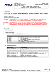
29-32-12 PB 401 CONF 00 — PRESSURE SWITCH — SYSTEM — REMOVAL/INSTALLATION
Brand: Airbus
|
Category: Switch
|
Size: 0.26 MB
Advertisement
Airbus A320 Series Instructions Manual (13 pages)
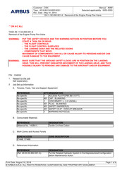
Removal of the Engine Pump Fire-Valve
Brand: Airbus
|
Category: Aircrafts
|
Size: 0.26 MB
Airbus A320 Series Manual (9 pages)
Brand: Airbus
|
Category: Aircrafts
|
Size: 0.11 MB
Advertisement
Related Products
-
Airbus A319
-
Airbus A321
-
Airbus A320-214
-
Airbus A330
-
Airbus A340-200
-
Airbus A340 Series
-
Airbus A340-300
-
Airbus A318
Airbus Categories
Aircrafts
Automobile Accessories
Radio
![]()
Switch
![]()
Cell Phone
More Airbus Manuals
- Manuals
- Brands
- Airbus Manuals
- Aircrafts
- A320 Series
Manuals and User Guides for Airbus A320 Series. We have 5 Airbus A320 Series manuals available for free PDF download: Manual, Instructor Support, Instructions Manual
Airbus A320 Series Manual (630 pages)
Brand: Airbus
|
Category: Aircrafts
|
Size: 13.24 MB
Table of Contents
-
-
Introduction to the Preventing Identified Risks
174
-
Questions and Suggestions
175
-
Aop-10 Design Philosophy
199
-
Arrangement of Panels
205
-
Dark Cockpit Concept for Overhead Panel
207
-
Cockpit Controls — Best Practices
208
-
Flight Control Protections
211
-
Flying in Reconfiguration Laws
213
-
General Design and Utilization Principles
215
-
Normal Procedures — Standard Operating Procedures (SOP)
216
-
Normal Procedures — Supplementary Procedures
216
-
Abnormal and Emergency Procedures
217
-
Tasksharing Rules and Communication
219
-
FCU/AFS and EFIS Control Panels
220
-
How to Conduct Briefings
221
-
Continued on the Following Page
224
-
Management of Abnormal Operations
229
-
One Procedure at a Time
229
-
Sequence of Procedure
229
-
Tasksharing Rules for Cockpit Controls Operation
231
-
Tasksharing Rules for Thrust Levers Operation
231
-
Handling Overhead Panel Control
232
-
ECAM/QRH/OEB Actions Completed
237
-
Golden Rules for Pilots
247
-
-
Practical Use of the Bird
257
-
AS-FG Flight Guidance
261
-
AS-FG-10-1 Auto Flight
261
-
Managed and Selected Modes
261
-
Main Interfaces with the AP/FD
262
-
Recommended Practice for Autopilot (AP) Engagement
263
-
Use of the FD Without the AP
263
-
Operations with One Engine Inoperative
266
-
To Set Autothrust to off
267
-
Autothrust Use — Summary
270
-
AS-FM Flight Management
273
-
ZFW — ZFWCG Entry Errors
276
-
Operational Recommendations
282
-
Intruder Classification
287
-
Analysis of Weather Radar Data
302
-
Operations in Convective Weather
308
-
-
PR-NP Normal Procedures
327
-
Secured and Transit Stop
331
-
Preliminary Cockpit Preparation
333
-
Preliminary Takeoff Performance Computation
334
-
Seating Position and Adjustment of Rudder Pedals
343
-
Taxi Roll and Steering
347
-
180 Degrees Turn on Runway
350
-
Departure Briefing Confirmation
353
-
Last Data Changes before Takeoff
353
-
Tail Strike Avoidance
359
-
Acceleration Altitude
361
-
Slats/Flaps Retraction at Heavy Weight
361
-
Low Altitude Level off
362
-
Noise Abatement Takeoff
362
-
Overspeed Warning During Slats/Flaps Transition
362
-
Small Altitude Changes
366
-
Undue Activation of Go-Around Phase
367
-
Vertical Performance Predictions
367
-
Speed Decay During Cruise
373
-
Altitude Considerations
374
-
Content of a Landing Performance Data Crosscheck
386
-
Computation Principles
389
-
Guidance and Monitoring
390
-
Holding Speed and Configuration
395
-
In the Holding Pattern
395
-
Discontinued Approach
398
-
Intermediate Approach
401
-
Approach Using LOC G/S Guidance
405
-
Approach Using LOC G/S for CATII CATIII
406
-
Approach Using FINAL APP Guidance
412
-
Approach Using FPA Guidance
419
-
Approach and Landing Techniques
433
-
Transition to Visual References
433
-
Tail Strike Avoidance
441
-
Considerations about Go-Around
443
-
AP/FD Go-Around Phase Activation
444
-
Leaving the Go-Around Phase
448
-
Securing the Aircraft
459
-
Aircraft Deicing/Anti-Icing on Ground
462
-
Operational Recommendations
473
-
Radius to Fix (RF) Legs
491
-
Introduction to Emergency Electrical Configuration
507
-
Engine Abnormal Response
509
-
Engine Failure — General
520
-
Engine Failure at Low Speed (on Ground)
520
-
Engine Failure after V1
521
-
Engine Failure During Cruise
525
-
Engine Failure During Initial Climb
525
-
One Engine Inoperative — Circling
532
-
One Engine Inoperative — Go-Around
532
-
One Engine Inoperative — Landing
533
-
Thrust Levers Management in the Case of Inoperative Reverser(S)
533
-
Abnormal Flaps/Slats Configuration
535
-
Dual Hydraulic Failures
539
-
Hydraulic Generation Particularities
539
-
Landing with Abnormal L/G
545
-
Nose Wheel Steering Fault
546
-
Taxi with Deflated or Damaged Tires
546
-
Wheel Tire Damage Suspected
547
-
Cockpit Windshield/Window Cracked
551
-
Flight Crew Incapacitation
560
-
Handling the Aircraft in the Case of Severe Damage
561
-
Volcanic Ash Encounter
578
-
Upset Prevention and Recovery
579
-
Unreliable Airspeed Indications
586
-
Unreliable Speed Indication» QRH Procedure
589
-
Dual Radio Altimeter Failure
605
-
Smoke / Fumes Detection and Procedure Application
607
-
Coordination with Cabin Crew
608
-
Smoke / Fumes / AVNCS Smoke QRH Procedure
609
-
Lithium Battery Fire in the Cockpit
614
Airbus A320 Series Instructor Support (208 pages)
Brand: Airbus
|
Category: Aircrafts
|
Size: 5.9 MB
Table of Contents
-
Aircraft Documentation
11
-
Cockpit Preparation and some Cg Considerations
13
-
Cruise — Descent and Approach Preparation — Approach Briefing
41
-
11/1 — General Approach Briefing
50
-
11/3 — Non Precision Approaches (Npa)
59
-
11/4 — Circling Approach
64
-
11/5 — Visual Approach
66
-
Precision Approaches — Cat II — Cat III
67
-
Landing, Flare, Rollout and Braking
78
-
Performance Considerations
100
-
Use of Flying References — Attitude or Bird (Fpv)
116
-
Flight Director / Autopilot / Athr — Mode Changes and Reversions
126
-
Fms Navigation Accuracy — Crosscheck, Position Update, Gps
130
-
Flight Controls — Highlights on Handling Characteristics
137
-
Flight Controls — Highlights on the Protections
144
-
Predictive and Reactive Windshear
148
-
Adverse Weather Operations
171
-
Ferry Flight with Landing Gear down
177
-
Wet and Contaminated Runways
178
-
B — Abnormal Operation
181
-
Rejected Take-Off (Refer Fcom 3-02-01)
189
-
Engine Failure/Fire after V1
191
-
Failure of some Engine Components
193
-
Emergency Electrical Configuration
195
-
Double Hydraulic Failure
198
-
Zfw Entry Error (Pilot’s Entry)
202
-
Double Radio Altimeter Failure
205
-
Unreliable Speed/Altitude Indication
207
Airbus A320 Series Manual (19 pages)
29-32-12 PB 401 CONF 00 — PRESSURE SWITCH — SYSTEM — REMOVAL/INSTALLATION
Brand: Airbus
|
Category: Switch
|
Size: 0.26 MB
Airbus A320 Series Instructions Manual (13 pages)
Removal of the Engine Pump Fire-Valve
Brand: Airbus
|
Category: Aircrafts
|
Size: 0.26 MB
Airbus A320 Series Manual (9 pages)
Brand: Airbus
|
Category: Aircrafts
|
Size: 0.11 MB
Related Products
-
Airbus A319
-
Airbus A321
-
Airbus A320-214
-
Airbus A330
-
Airbus A340-200
-
Airbus A340 Series
-
Airbus A340-300
-
Airbus A318
Airbus Categories
Aircrafts
Automobile Accessories
Radio
Modem
![]()
Switch
More Airbus Manuals
Flight Crew Operations Manual ( FCOM) The Boeing 757-200
Руководство по летной эксплуатации Боинг 757-200
Подробнее
 Quick Reference Handbook Boeing 757 QRH & Performance Inflight
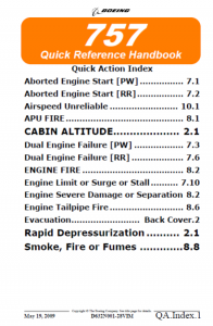 Quick Reference Handbook Boeing 757 QRH & Performance Inflight
B757 QRH & Performance Inflight. Quick Action Index. 757 Flight Crew Operations …
Суперджет 100. Руководство по летной эксплуатации
 Суперджет 100. Руководство по летной эксплуатации
Подробнее
Скачать Суперджет 100 руководство по летной эксплуатации с Hitfile.net
Скачать Суперджет 100 руководство по летной эксплуатации с Turbobit.net
Airbus A318/A319/A320/A321. Flight Crew Operating Manual
(Инструкция по летной эксплуатации самолетов Аэробус A318/A318/A320/A321).
Part 1 – Systems Description
Название: Airbus A318/A319/A320/A321. Flight Crew Operating Manual. Part 1 – Systems description (Описание систем).
Издательство: Airbus S.A.S
Страниц: 1995
Формат: PDF
Качество: Хорошее
Язык: Английский
Скачать AirbA318/A319/A320/A321. Flight Crew Operating Manual. Part 1 – Systems description с Hitfile.net
Скачать AirbA318/A319/A320/A321. Flight Crew Operating Manual. Part 1 – Part 1 – Systems description с Turbobit.net
Part 2 — Flight preparation (Подготовка к полету).
Название: Airbus A318/A319/A320/A321. Flight Crew Operating Manual. Part 2– Flight preparation
Издательство: Airbus S.A.S
Страниц: 885
Формат: PDF
Качество: Хорошее
Язык: Английский
Скачать AirbA318/A319/A320/A321. Flight Crew Operating Manual. Part 2 – Flight Preparation с Hitfile.net
Скачать AirbA318/A319/A320/A321. Flight Crew Operating Manual. Part 2 – Flight Preparation с Turbobit.net
Part 3 — Flight orerations (Полёты).
Название: Airbus A318/A319/A320/A321. Flight Crew Operating Manual. Part 3– Flight operations
Издательство: Airbus S.A.S
Страниц: 2089
Формат: PDF
Качество: Хорошее
Язык: Английский
Скачать AirbA318/A319/A320/A321. Flight Crew Operating Manual. Part 3– Flight operations с Hitfile.net
Скачать AirbA318/A319/A320/A321. Flight Crew Operating Manual. Part 3– Flight operations с Turbobit.net
Part 4-FMGS Pilot’s GUEDE (Руководство пилота).
Название: Airbus A318/A319/A320/A321. Flight Crew Operating Manual. Part 4– FMGS Pilot’s GUIDE
Издательство: Airbus S.A.S
Страниц: 1225
Формат: PDF
Качество: Хорошее
Язык: Английский
Скачать AirbA318/A319/A320/A321. Flight Crew Operating Manual. Part 4– FMGS Pilot’s GUIDE с Hitfile.net
Скачать AirbA318/A319/A320/A321. Flight Crew Operating Manual. Part 4– FMGS Pilot’s GUIDE с Turbobit.net
А320 — семейство узкофюзеляжных самолётов для авиалиний малой и средней протяжённости, разработанных европейским консорциумом «Airbus S.A.S». Выпущенный в 1988 году, он стал первым пассажирским самолётом, на котором была применена электродистанционная система управления (ЭДСУ «Fly-by-wire» по терминологии Эйрбаса).
Flight Crew Operations Manual ( FCOM) The Boeing 737-700/800
Руководство по летной эксплуатации Боинг 737-700/800
Подробнее
На чтение 4 мин Просмотров 8.5к. Опубликовано 15.05.2020
Содержание
- 1. Предполетная подготовка кабины
- 2. Руление, взлет, набор высоты
- 3. Подготовка к снижению, заход, посадка
- 4. Снижение в Open Descend (Двигатели на малом газу с начала снижения до входа в глиссаду)
- 5. Снижение в Vertical Speed, уход на второй круг Часть 1
- 6. Снижение в Vertical Speed, Визуальный заход – часть 2
- 7. Теория неточных заходов
- 8. Заход RNAV в режиме Final APP
- 9. Заход VOR в режиме NAV/FPA
- 10. Заход VOR в Режиме TRK/FPA
- 11. Запуск двигателей от устройства воздушного запуска при неработающей ВСУ
- 12. Разбираемся в базе данных FMGS/FMS
- 13. Процедуры FsLabs A320. One engine taxi после прилета.
- 14. Летаем по кругу, отрабатываем Touch and Go в Xplane на Toliss A321
- 15. Circle to Land в Родосе на FSlabs A320
- 16. EuroScope, первые шаги (2020) @ VATSIM ATC Client
- Метеорологический минимум. Что за зверь такой?
- 17. Стрим без Ильи, 737-800, Победа
- 18. Low visibility Take-off, CAT I approach.
Коллеги. Илья мой хороший товарищ и реальный пилот А320 разрешил разместить у нас на сайте материалы, которые он сделал самостоятельно, по которым вы научитесь правильно управлять самолетами семейства A320. С одной стороны пандемия злая штука, с другой стороны появившееся свободное время, пока самолеты на земле, позволило передать свой опыт и знания вам.
Знакомьтесь – Илья
После изучения всех представленных здесь материалов, можете начинать спорить: а посадит ли симмер самолет и выкладывать видео: ацените маю пасатку 😁.
Подписывайтесь на канал, а мы по мере появления новых видео, будем добавлять их в эту статью. Добавляйте в закладки. Найти вы ее всегда можете в разделе сайта Crew Room, или по тегам:
a320 / kran / аэрофлот / кран / савельев / Kran Airlines
😁
1. Предполетная подготовка кабины
2. Руление, взлет, набор высоты
3. Подготовка к снижению, заход, посадка
4. Снижение в Open Descend (Двигатели на малом газу с начала снижения до входа в глиссаду)
5. Снижение в Vertical Speed, уход на второй круг Часть 1
6. Снижение в Vertical Speed, Визуальный заход – часть 2
7. Теория неточных заходов
8. Заход RNAV в режиме Final APP
9. Заход VOR в режиме NAV/FPA
10. Заход VOR в Режиме TRK/FPA
11. Запуск двигателей от устройства воздушного запуска при неработающей ВСУ
12. Разбираемся в базе данных FMGS/FMS
13. Процедуры FsLabs A320. One engine taxi после прилета.
14. Летаем по кругу, отрабатываем Touch and Go в Xplane на Toliss A321
15. Circle to Land в Родосе на FSlabs A320
16. EuroScope, первые шаги (2020) @ VATSIM ATC Client
Метеорологический минимум. Что за зверь такой?
17. Стрим без Ильи, 737-800, Победа
Запись стрима, полёт экипажем на ZIBO 737-800 с манерами от Летчика Лехи:)
18. Low visibility Take-off, CAT I approach.
А еще у Ильи замечательные фотки в Инстаграмме. Частью я с вами поделюсь тут, а остальное кому понравилось и интересно, можете посмотреть у него в профиле
Купить за рубли вариант 1
Купить через Леонида (выгоднее)

В настоящий момент изучаю семейство Аэробусов. Нашел много разного материала и мануалов (исключительно на английском), но ваше внимание хочу обратить на великолепную работу Павла (DOB117) Козловского по A320 Wilco. На его создание ушло более года. Забрать мануал можно здесь.
Вот содержание данной работы:
Введение
ГЛАВА 1.      Матчасть
ГЛАВА 2.      Общие положения, начало планирования рейса
ГЛАВА 3.      Загрузка на стоянке
ГЛАВА 4.      Предполетная подготовка
ГЛАВА 5.      Продолжение предполетной подготовки. Расчет топлива
ГЛАВА 6.      Расчет взлетных параметров
ГЛАВА 7.      Буксировка и запуск
ГЛАВА 8.      Руление
ГЛАВА 9.      Взлет
ГЛАВА 10.     Набор высоты
ГЛАВА 11.     Полет на эшелоне
ГЛАВА 12.     Снижение
ГЛАВА 13.     Заход на посадку
ГЛАВА 14.     Посадка
ГЛАВА 15.     Руление на стоянку и послеполетные работы
ПРИЛОЖЕНИЕ 1. Normal Check List
Об авторе
This entry was posted on 25.08.2011, 13:52 and is filed under Мануалы, статьи и др.. You can follow any responses to this entry through RSS 2.0.
Вы можете оставить отзыв или обратную ссылку с вашего сайта.
Министерство Транспорта Российской Федерации
Федеральная служба по надзору в сфере транспорта
АНОО «С 7 Тренинг»
Конструкция ВС А-319/320/321
Учебное пособие для подготовки бортпроводников
Под редакцией начальника Отдела подготовки авиационного персонала
Д.В. Бакина
Москва
2011
Рецензенты:
Конструкция ВС А-319/320/321: учебное пособие для подготовки бортпроводников. / Под. ред. Д.В. Бакина. М.: АНОО «С 7 Тренинг», 2011.
– 96 страниц.
Учебное пособие подготовлено для преподавания дисциплины «Конструкция ВС А-319/320/321» при проведении курсов первоначальной подготовки, переподготовки и повышения квалификации бортпроводников на воздушное судно А- 319/320/321. При разработке учебного пособия, за основу взято воздушное судно А- 320, так как оно является типичным представителем линейки самолетов А-319/320/321.
В учебном пособии рассмотрены конструктивные особенности ВС А- 319/320/321 (типовая компоновка и оборудование), дано общее описание самолетов А- 319/320/321, размеров и оборудования пассажирской кабины, панелей управления, освещения ВС, систем связи, туалетных комнат, рабочих стоек, дверей, трапов и аварийных выходов.
Системы самолета имеют продуманные конструктивные решения, в частности в отношении наличия удобного расположения и конструкций панелей, люков и дверей, обеспечивающего легкий доступ при обслуживании. Бортпроводник должен знать конструкцию самолета, чтобы в случае каких то непредвиденных ситуаций (воздушные ямы, гроза) уметь объяснить пассажирам причину тряски самолета, успокоить их, не компрометируя экипаж и компанию. Одной из задач бортпроводника является: знать конструкцию ВС и при необходимости применить свои знания и навыки в случаях возникновения внештатных ситуаций.
Данное учебное пособие не является руководством по эксплуатации ВС А- 319/320/321 и может быть использовано только в учебных целях в АНОО «С 7 Тренинг».
Учебное пособие рассмотрено и одобрено Методическим Советом АНОО «С 7 Тренинг», протокол заседания № ___ от «___» _________ 20 ___ г.
© М.: АНОО «С 7 Тренинг», 2011.
2
Перечень использованных аббревиатур и их толкование
APU – Auxiliary Power Unit (Вспомогательная cиловая установка). PSU – Passenger Service Unit (Сервисная панель пассажира).
LSU – Lavatory Service Unit. (Сервисная панель туалетной комнаты)
INTERPHONE – Самолетное переговорное устройство, используется для внутреннего общения между членами экипажа.
PA – Самолетное громкоговорящее устройство, используется для публичного обращения к пассажирам.
MRT – Manual Release Tool (Инструмент ручного открытия кислородных блоков). CIDS – Cabin Intercommunication Data System (Микропроцессор).
DEU – Decoder Encoder Unit (Декодирующее устройство).
FAP – Forward Attendant Panel (Передняя панель управления бортпроводника). PTP – Programming and Test Panel (Панель программирования и тестирования).
CAM – Cabin Assignment Module (Модуль содержащий программное обеспечения для работы систем пассажирской кабины)
AAP – Additional Attendant Panel (Дополнительная (задняя панель управления бортпроводника).
ACP – Area Call Panel (Панель оповещения).
PRA – Prerecorded announcement (Звуковоспроизводящее устройство). PTT – Push To Talk (Клавиша на микрофоне).
Перечень используемой литературы
1.Cabin Crew Operating Manual (CCOM) A319/320/321, AIRBUS INDUSTRIE;
2.Flight Crew Operating Manual (FCOM) A-319/320/321, AIRBUS INDUSTRIE.
3
|
СОДЕРЖАНИЕ |
||||
|
Перечень использованных аббревиатур и их толкование |
3 |
|||
|
Перечень используемой литературы |
3 |
|||
|
Содержание |
4 |
|||
|
Часть 1. |
Описание самолета |
6 |
||
|
1.1. |
Летно-технические данные самолета |
6 |
||
|
1.2. |
Основные размеры самолета |
7 |
||
|
1.3. Вспомогательная Силовая Установка (APU) |
8 |
|||
|
1.4. |
Электрическая система самолета |
8 |
||
|
1.5. Система кондиционирования воздуха и герметизации |
8 |
|||
|
(наддува) |
||||
|
1.6. |
Пассажирская кабина |
10 |
||
|
1.6.1. |
Двери пассажирской кабины |
10 |
||
|
1.6.2. |
Кухни |
11 |
||
|
1.6.3. |
Туалетные комнаты |
12 |
||
|
1.6.4. Багажные полки для пассажиров |
12 |
|||
|
1.6.5. |
Шкафы и перегородки |
13 |
||
|
1.7. Места для пассажиров и бортпроводников |
13 |
|||
|
1.7.1. |
Места для пассажиров |
13 |
||
|
1.7.2. |
Места для бортпроводников |
14 |
||
|
1.7.3. |
Станции бортпроводников |
15 |
||
|
1.8. Сервисная панель пассажиров PSU. Кислородная |
16 |
|||
|
система для пассажиров |
||||
|
Часть 2. Микропроцессор CIDS. Панели бортпроводника |
18 |
|||
|
2.1. |
Микропроцессор (CIDS — Cabin Intercommunication |
18 |
||
|
Data System) |
||||
|
2.2. Передняя панель управления бортпроводника FAP |
20 |
|||
|
2.3. Панель программирования и тестирования PTP |
23 |
|||
|
2.4. |
Дополнительная (задняя) панель управления AAP |
26 |
||
|
2.5. |
Индикационная (информационная) панель AIP |
27 |
||
|
2.6. |
Панель оповещения ACP |
28 |
||
|
Часть 3. |
Система освещения |
29 |
||
|
3.1. |
Освещение пассажирской кабины |
29 |
||
|
3.1.1. Управление освещением пассажирской кабины |
30 |
|||
|
3.1.2. Основное освещение пассажирских салонов |
32 |
|||
|
3.1.3. |
Освещение вестибюлей самолета |
32 |
||
|
3.1.4. |
Индивидуальное освещение |
32 |
||
|
3.1.5. |
Освещение туалетных комнат |
32 |
||
|
3.1.6. |
Рабочее освещение |
32 |
||
|
3.2. |
Аварийное освещение |
32 |
||
|
3.2.1. Внутреннее аварийное освещение самолета |
33 |
|||
|
3.2.2. |
Аварийный фонарь |
35 |
||
|
3.2.3. |
Внешнее аварийное освещение |
35 |
||
|
Часть 4. |
Система связи |
37 |
||
|
4.1. Самолетное переговорное устройство (Interphone) |
37 |
|||
|
4.2. |
Самолетное громкоговорящее устройство (РА) |
40 |
||
|
4.3. Связь пассажиров с кабинным экипажем |
43 |
|||
|
4.3.1. Вызов бортпроводника из пассажирской |
43 |
|||
|
кабины |
||||
|
4.3.2. Вызов бортпроводника из туалетной комнаты |
44 |
|||
|
4.4. |
Информационное табло для пассажиров |
45 |
4
|
Часть 5. |
Туалетные комнаты самолета |
46 |
||||||
|
5.1. |
Месторасположение туалетов на самолете |
46 |
||||||
|
5.2. |
Описание туалетных комнат |
46 |
||||||
|
5.3. |
Состав оборудования туалетной комнаты |
47 |
||||||
|
5.4. |
Кран системы водоснабжения туалетной комнаты |
48 |
||||||
|
5.5. |
Детектор дыма туалетной комнаты |
49 |
||||||
|
5.6. |
Стационарный огнетушитель туалетной комнаты |
51 |
||||||
|
5.7. |
Возможные неисправности в туалетной комнате |
52 |
||||||
|
5.7.1. Кран смесителя раковины не отключает воду |
52 |
|||||||
|
5.7.2. |
Переполнение канализационного бака. |
52 |
||||||
|
5.7.3. Неисправность вакуумной системы |
смыва |
52 |
||||||
|
унитаза |
||||||||
|
Часть 6. |
Система водоснабжения и канализации самолета |
52 |
||||||
|
6.1. |
Система водоснабжения |
52 |
||||||
|
6.2. |
Канализационная система |
53 |
||||||
|
Часть 7. |
Кухни самолета |
55 |
||||||
|
7.1. |
Описание кухонь самолета |
55 |
||||||
|
7.2. |
Электроснабжение кухонь |
56 |
||||||
|
7.3. |
Водоснабжение кухонь |
56 |
||||||
|
7.4. |
Расположение кухонь |
57 |
||||||
|
7.5. |
Канализационная система кухонь |
57 |
||||||
|
7.6. |
Возможные неисправности в кухне |
57 |
||||||
|
7.6.1. |
Засор слива раковины |
57 |
||||||
|
7.6.2. Течь воды в кухне |
58 |
|||||||
|
Часть 8. |
Двери, аварийные трапы, запасные аварийные выходы |
58 |
||||||
|
8.1. |
Двери самолета |
58 |
||||||
|
8.2. |
Открытие дверей самолета снаружи |
65 |
||||||
|
8.3. |
Вспомогательное место у двери |
67 |
||||||
|
8.4 |
Ограничительный барьер |
67 |
||||||
|
8.5. |
Запасные аварийные выходы |
68 |
||||||
|
8.5.1. Запасные |
аварийные |
выходы |
на |
крыло |
68 |
|||
|
самолета A-319/320 |
||||||||
|
8.5.2. Запасные |
аварийные |
выходы пассажирской |
72 |
|||||
|
кабины самолета A-321 |
||||||||
|
8.6. |
Средства эвакуации самолета А-319/320/321 |
74 |
||||||
|
8.6.1. Средства |
эвакуации |
основных |
аварийных |
74 |
||||
|
выходов А-319/320/321 |
||||||||
|
8.6.2. Средства |
эвакуации |
запасных |
аварийных |
77 |
||||
|
выходов А-319/320 |
||||||||
|
8.6.3. Средства |
эвакуации |
запасных |
аварийных |
79 |
||||
|
выходов А-321 |
||||||||
|
Часть 9. |
Кабина летного экипажа |
80 |
||||||
|
9.1 |
Дверь кабины пилотов |
80 |
||||||
|
9.2. |
Кресла для членов летного экипажа |
82 |
||||||
|
9.2. |
Запасные аварийные выходы в кабине пилотов |
83 |
||||||
|
9.3.1. |
Форточки кабины пилотов |
83 |
||||||
|
9.3.2. Аварийные канаты кабины пилотов |
85 |
|||||||
|
Часть 10. |
Система EVAC (команда на эвакуацию) |
86 |
||||||
|
Часть 11. |
Вопросы для самотестирования |
90 |
5
Часть 1. Описание самолета
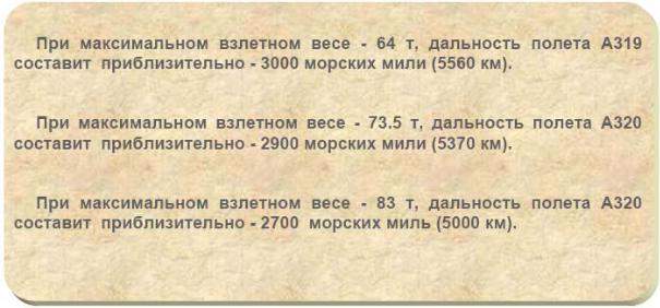
Эта часть содержит описание основных летно-технических данных ВС А- 319/320/321.
1.1. Летно-технические данные самолета
Семейство самолета А-320 (А-319/320/321) является самым передовым семейством однопроходных узкофюзеляжных самолетов на сегодняшний день. Семейство А-320 используется для выполнения полетов на средние дистанции. Управление самолетом обеспечивается надежными компьютеризированными системами.
На эти самолеты по выбору эксплуатанта могут устанавливаться двигатели
International Aero Engines или CFM International.
6

1.2 Основные размеры самолета
Рис. 1
7
1.3. Вспомогательная Силовая Установка (APU)
APU — газовый турбинный двигатель, который может использоваться на земле и в воздухе. APU установлен в хвостовой части самолета.. На земле, APU обеспечивает воздушное судно электроэнергией, которая в свою очередь обеспечивает работу жизненно важных систем самолета, если работа этих систем не может быть обеспечена наземным обслуживанием.
В полете, APU может использоваться в качестве резервного источника, отбора воздуха для системы кондиционирования.
1.4. Электрическая система самолета
Электрическая система обеспечивает воздушное судно переменным током — 115 вольт и постоянным током — 28 вольт.
На земле, электропитание может быть обеспечено APU или наземным источником питания, предоставленным наземным обслуживанием.
Если выходит из строя один и более электрических генераторов самолета, электрическое питание кухонь самолетов отключается автоматически.
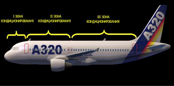
1.5. Система кондиционирования воздуха и герметизации (наддува)
Обычно, отбор воздуха для системы кондиционирования, и герметизации обеспечивается работающими двигателями самолета. APU может также использоваться для отбора воздуха (для работы этих систем).
Полностью автоматическая система кондиционирования обеспечивает приток свежего воздуха и поддержание температурного режима в трех зонах на борту воздушного судна (Рис.2):
—кабине летного экипажа;
—передней пассажирской кабине;
—задней пассажирской кабине.
Рис.2
Температура в пассажирской кабине, кабине пилотов регулируется из кабины пилотов с панели управления системы кондиционирования (Рис 3).
Состояние температурного режима в кабине пилотов и двух зонах пассажирской кабины отображается на жидкокристаллическом мониторе ECAM в кабине пилотов.
8

Рис. 3
Вентиляционная система пассажирских салонов самолета обеспечивает поступление свежего воздуха. Часть поступающей воздушной массы смешивается со свежим (из-за борта) воздухом обеспечивая рециркуляцию.
Поступление воздуха происходит через вентиляционные отверстия, расположенные над и под багажными полками. Выход воздуха происходит через вентиляционные отверстия, расположенные у пола (Рис. 4).
Рис. 4
Вентиляция кухонь и туалетов установлена таки образом, чтобы не допустить попадание неприятных запахов в пассажирские салоны самолета. Воздух принудительно извлекается из этих помещений пассажирской кабины через вентиляционные отверстия и выходит за борт воздушного судна.
Ниже, приведены негерметизируемые зоны на воздушном судне А-320 (Рис.5).
9
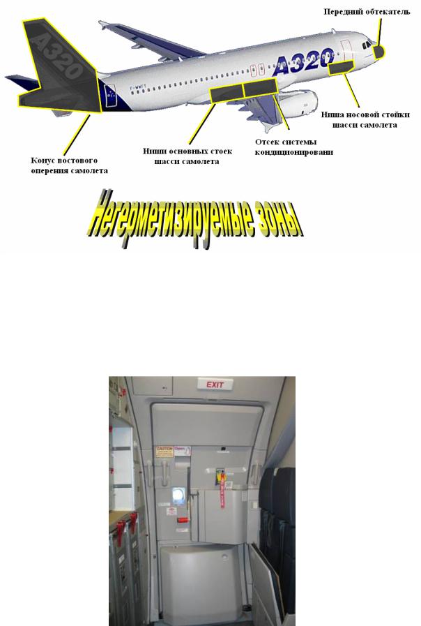
Рис. 5
1.6. Пассажирская кабина
1.6.1. Двери пассажирской кабины
Левый (основной) борт фюзеляжа самолета оборудован двумя (основными) дверями, предназначенными для входа и выхода пассажиров. Основные двери (1L и 3L) расположены в носовой и хвостовой части воздушного судна. Двери (Рис. 6) крепятся на петлях. Для фиксации двери в открытом положении, предусмотрен фиксатор.
Рис.6
10
Соседние файлы в предмете [НЕСОРТИРОВАННОЕ]
- #
- #
- #
- #
- #
- #
- #
- #
- #
- #
- #
На чтение 4 мин Просмотров 9.1к. Опубликовано 15.05.2020
Содержание
- 1. Предполетная подготовка кабины
- 2. Руление, взлет, набор высоты
- 3. Подготовка к снижению, заход, посадка
- 4. Снижение в Open Descend (Двигатели на малом газу с начала снижения до входа в глиссаду)
- 5. Снижение в Vertical Speed, уход на второй круг Часть 1
- 6. Снижение в Vertical Speed, Визуальный заход – часть 2
- 7. Теория неточных заходов
- 8. Заход RNAV в режиме Final APP
- 9. Заход VOR в режиме NAV/FPA
- 10. Заход VOR в Режиме TRK/FPA
- 11. Запуск двигателей от устройства воздушного запуска при неработающей ВСУ
- 12. Разбираемся в базе данных FMGS/FMS
- 13. Процедуры FsLabs A320. One engine taxi после прилета.
- 14. Летаем по кругу, отрабатываем Touch and Go в Xplane на Toliss A321
- 15. Circle to Land в Родосе на FSlabs A320
- 16. EuroScope, первые шаги (2020) @ VATSIM ATC Client
- Метеорологический минимум. Что за зверь такой?
- 17. Стрим без Ильи, 737-800, Победа
- 18. Low visibility Take-off, CAT I approach.
Коллеги. Илья мой хороший товарищ и реальный пилот А320 разрешил разместить у нас на сайте материалы, которые он сделал самостоятельно, по которым вы научитесь правильно управлять самолетами семейства A320. С одной стороны пандемия злая штука, с другой стороны появившееся свободное время, пока самолеты на земле, позволило передать свой опыт и знания вам.
Знакомьтесь – Илья
После изучения всех представленных здесь материалов, можете начинать спорить: а посадит ли симмер самолет и выкладывать видео: ацените маю пасатку 😁.
Подписывайтесь на канал, а мы по мере появления новых видео, будем добавлять их в эту статью. Добавляйте в закладки. Найти вы ее всегда можете в разделе сайта Crew Room, или по тегам:
a320 / kran / аэрофлот / кран / савельев / Kran Airlines
😁
1. Предполетная подготовка кабины
2. Руление, взлет, набор высоты
3. Подготовка к снижению, заход, посадка
4. Снижение в Open Descend (Двигатели на малом газу с начала снижения до входа в глиссаду)
5. Снижение в Vertical Speed, уход на второй круг Часть 1
6. Снижение в Vertical Speed, Визуальный заход – часть 2
7. Теория неточных заходов
8. Заход RNAV в режиме Final APP
9. Заход VOR в режиме NAV/FPA
10. Заход VOR в Режиме TRK/FPA
11. Запуск двигателей от устройства воздушного запуска при неработающей ВСУ
12. Разбираемся в базе данных FMGS/FMS
13. Процедуры FsLabs A320. One engine taxi после прилета.
14. Летаем по кругу, отрабатываем Touch and Go в Xplane на Toliss A321
15. Circle to Land в Родосе на FSlabs A320
16. EuroScope, первые шаги (2020) @ VATSIM ATC Client
Метеорологический минимум. Что за зверь такой?
17. Стрим без Ильи, 737-800, Победа
Запись стрима, полёт экипажем на ZIBO 737-800 с манерами от Летчика Лехи:)
18. Low visibility Take-off, CAT I approach.
А еще у Ильи замечательные фотки в Инстаграмме. Частью я с вами поделюсь тут, а остальное кому понравилось и интересно, можете посмотреть у него в профиле
В настоящий момент изучаю семейство Аэробусов. Нашел много разного материала и мануалов (исключительно на английском), но ваше внимание хочу обратить на великолепную работу Павла (DOB117) Козловского по A320 Wilco. На его создание ушло более года. Забрать мануал можно здесь.
Вот содержание данной работы:
Введение
ГЛАВА 1.      Матчасть
ГЛАВА 2.      Общие положения, начало планирования рейса
ГЛАВА 3.      Загрузка на стоянке
ГЛАВА 4.      Предполетная подготовка
ГЛАВА 5.      Продолжение предполетной подготовки. Расчет топлива
ГЛАВА 6.      Расчет взлетных параметров
ГЛАВА 7.      Буксировка и запуск
ГЛАВА 8.      Руление
ГЛАВА 9.      Взлет
ГЛАВА 10.     Набор высоты
ГЛАВА 11.     Полет на эшелоне
ГЛАВА 12.     Снижение
ГЛАВА 13.     Заход на посадку
ГЛАВА 14.     Посадка
ГЛАВА 15.     Руление на стоянку и послеполетные работы
ПРИЛОЖЕНИЕ 1. Normal Check List
Об авторе
This entry was posted on 25.08.2011, 13:52 and is filed under Мануалы, статьи и др.. You can follow any responses to this entry through RSS 2.0.
Вы можете оставить отзыв или обратную ссылку с вашего сайта.
- Manuals
- Brands
- Airbus Manuals
- Aircrafts
- A320 Series
- Instructor support
-
Contents
-
Table of Contents
-
Bookmarks
Quick Links
A340 INSTRUCTOR SUPPORT
OPERATION WITH ABNORMALS
TRAINING & FLIGHT OPERATIONS SUPPORT DIVISION
A320 Family
Instructor Support
Ref: UHG01041
DATE: OCT 1999
Page 1
F7PXX01
Related Manuals for Airbus A320 Series
Summary of Contents for Airbus A320 Series
-
Page 1
A340 INSTRUCTOR SUPPORT OPERATION WITH ABNORMALS TRAINING & FLIGHT OPERATIONS SUPPORT DIVISION A320 Family Instructor Support Ref: UHG01041 DATE: OCT 1999 Page 1 F7PXX01… -
Page 3
— E. TARNOWSKI — A320 INSTRUCTOR SUPPORT The purpose of this document is to supply some background and concentrating knowledge and to be an assistance for Instructors in terms of properly delivering their briefing and in order to be ready to answer trainees questions. This document does not replace the FCOMs, which are the reference. -
Page 5: Table Of Contents
A320 INSTRUCTOR SUPPORT CONTENTS A320 INSTRUCTOR SUPPORT SUMMARY __________________________ NORMAL OPERATION AIRCRAFT DOCUMENTATION ………………. 3 COCKPIT PREPARATION AND SOME CG CONSIDERATIONS ……..5 TAKE OFF BRIEFING ………………….13 ENGINE START ……………………. 14 TAXI AND BRAKING ………………….16 TAKE OFF…………………….. 20 CLIMB ……………………..
-
Page 6
A320 INSTRUCTOR SUPPORT CONTENTS 12 — PRECISION APPROACHES — CAT II — CAT III…………..59 13 — VAPP DETERMINATION………………..66 14 — LANDING, FLARE, ROLLOUT AND BRAKING …………..70 15 — GO AROUND……………………80 16 — ETOPS ……………………..82 17 — RVSM ……………………..90 18 — PERFORMANCE CONSIDERATIONS ……………. -
Page 7
A320 INSTRUCTOR SUPPORT CONTENTS B – ABNORMAL OPERATION ECAM PHILOSOPHY ………………….. 175 REJECTED TAKE-OFF (REFER FCOM 3-02-01) …………181 ENGINE FAILURE/FIRE AFTER V1…………….. 183 FAILURE OF SOME ENGINE COMPONENTS …………..185 EMERGENCY ELECTRICAL CONFIGURATION …………. 187 DOUBLE HYDRAULIC FAILURE………………190 ABNORMAL SLATS/FLAPS ……………….. -
Page 8
A320 INSTRUCTOR SUPPORT CONTENTS THIS PAGE INTENTIONALLY LEFT BLANK DATE: JAN 2001 Page iv UDYXX02… -
Page 9: Normal Operation
A320 INSTRUCTOR SUPPORT NORMAL OPERATION A. NORMAL OPERATION DATE: JAN 2001 Page 1 UDY0102…
-
Page 10
A320 INSTRUCTOR SUPPORT NORMAL OPERATION THIS PAGE INTENTIONALLY LEFT BLANK DATE: JAN 2001 Page 2 UDY0102… -
Page 11: Aircraft Documentation
A320 INSTRUCTOR SUPPORT NORMAL OPERATION 1 — AIRCRAFT DOCUMENTATION The MMEL and MEL The MMEL is the Master Minimum Equipment List published by the A/C manufacturer and certified. It allows an aircraft to be dispatched with some items of equipment or some functions inoperative — provided some specific limitations or procedures, or maintenance actions are carried out — in order to avoid delays or cancellations.
-
Page 12
A320 INSTRUCTOR SUPPORT NORMAL OPERATION General Operational Rules for the MEL: 1. The MEL theoretically applies to Revenue flights (out of base, the A/C should be clean of failures, or hold items must be mentioned in the technical log and approved). 2. -
Page 13: Cockpit Preparation And Some Cg Considerations
A320 INSTRUCTOR SUPPORT NORMAL OPERATION 2 — COCKPIT PREPARATION AND SOME CG CONSIDERATIONS Cockpit preparation » Do not pressurize the yellow hydraulic system without advising the ground maintenance crew. » If a flight control surface position, displayed on the ECAM FLT/CTL page, does not correspond to the handle position, advise the maintenance crew prior to acting on an hydraulic pump.
-
Page 14
A320 INSTRUCTOR SUPPORT NORMAL OPERATION FMGS programming The normal sequence of FMS programming consists in filling up Navigation Data and then Performance data: Status page Init A page F.PNL A page Navigation Data Sec FPLN Rad Nav Page Init B page Performance Data Perf pages This sequence of data entry is the most practical;… -
Page 15
A320 INSTRUCTOR SUPPORT NORMAL OPERATION NOTE: It often happens that the loadsheet is brought very late to the crew – However in many cases the crew knows what the expected ZFW is, how much fuel is required for the sector. Thus the crew know the expected TOW which allows then to prepare the expected T/O speeds and FLX TEMP. -
Page 16
A320 INSTRUCTOR SUPPORT NORMAL OPERATION The climb performance itself: For example, if a climb gradient of 5% is required (e.g. due to obstacles) in the previous take-off conditions, the MTOW is reduced from 257.6 t down to 256.2 t when CG varies from 26% to full forward CG. -
Page 17
A320 INSTRUCTOR SUPPORT NORMAL OPERATION • Maneuvering criteria — Maneuver point Depending upon the CG location, a given deflection of the elevator causes a more or less sharp aircraft maneuver. In other words, the CG has a direct influence on the maneuverability of the aircraft. If a very small deflection of the elevator causes «a lot of g», the efficiency of the elevator is very high;… -
Page 18
A320 INSTRUCTOR SUPPORT NORMAL OPERATION • Structural Considerations The CG cannot be too much forward due to Nose Gear structural limits; it cannot be too much AFT due to wing and main landing gear strut limit. • Loading Considerations All the previous criterias allow to determine limits which, for example, would favor AFT CG configurations for obvious performance efficiency. -
Page 19
A320 INSTRUCTOR SUPPORT NORMAL OPERATION Typical resulting CG envelope: # Performance / loading compromise at take-off $ Nose gear strength structural limit % Main gear strength structural limit & Alpha floor limit ‘ Nose gear adherence limit ( Alpha floor limit (landing) The inflight limit is deduced from the take-off / Landing envelope by adding a 2% margin, provided all handling characteristics criteria are fullfilled. -
Page 20
A320 INSTRUCTOR SUPPORT NORMAL OPERATION PF/PNF task sharing and cockpit preparation sequence and scan The FCOM and QRH detail this essential phase of the flight. A particular geographic scan has been developed in order to maximize the resource involvement in the spirit of ACRM. Accordingly the PF/PNF concept applies from the time the crew arrives at the aircraft till they leave the machine. -
Page 21: Take Off Briefing
A320 INSTRUCTOR SUPPORT NORMAL OPERATION 3 — TAKE OFF BRIEFING The main objective of the Take off briefing is for the PF to inform the PNF of his intended course of actions during Take off and initial climb, in normal and abnormal situations. It may be completed by specific Captain’s instructions. Any misunderstanding shall be clarified through questions.
-
Page 22: Engine Start
A320 INSTRUCTOR SUPPORT NORMAL OPERATION 4 — ENGINE START The normal engine start procedure is the AUTO START procedure; the MANUAL START procedure is used exceptionally in specific cases. During an AUTO START procedure the FADEC protects the engines against HOT, HUNG START, START STALL …, it detects these phenomena and takes the appropriate action (reducing the fuel flow, or cutting it off, cranking the engine, attempting a new start etc.
-
Page 23
A320 INSTRUCTOR SUPPORT NORMAL OPERATION Furthermore, the starter engagement is limited in time and in number of successive attempts: CFM: 4 times 2 mn with 20 sec between each start. IAE: 2 times 2 mn + 1 time 1 mn with 15 sec between each start. This is the reason why the use of the stopwatch is recommended. -
Page 24: Taxi And Braking
A320 INSTRUCTOR SUPPORT NORMAL OPERATION 5 — TAXI AND BRAKING Before taxiing, check NW STREERG DISC amber MEMO is not displayed on ECAM to confirm NWS is available. During taxi, there are several issues: taxi roll and steering, braking. Taxi roll and steering In order to initiate the taxi roll, the use of minimum thrust is recommended to avoid FOD (N1 40 % max).
-
Page 25
A320 INSTRUCTOR SUPPORT NORMAL OPERATION Minimum Turn Radius (assuming symmetrical thrust and no differential braking). The figures are provided for A320-200. The minimum runway width (pavement) required for 180° turns is 30 m (99 ft). The turn application assumes symmetrical thrust and no differential braking. The specific 180° turn procedure is described in A320 FCOM 3.03.10. Nose radius: A319 16.6 m… -
Page 26
A320 INSTRUCTOR SUPPORT NORMAL OPERATION OVERSTEERING TECHNIQUE For A 321 (longer a/c), it may be necessary to consider oversteering technique, main gear being 20 m behind the pilot. In case of a 180° turn on the runway a specific procedure is provided in SOP. Keep in mind that: You should not let the G/S drop below 8 kts during the maneuver in order to avoid stopping. -
Page 27
A320 INSTRUCTOR SUPPORT NORMAL OPERATION Parking brake particulars: Note that, when the parking brake is ON, pressing on the pedals has no effect on the braking. Consequently if for any reason the aircraft moves forward while parking brake is ON, the parking brake must be released in order to get braking efficiency from the pedals (on latest A320s, a modification provides the availability of pedal braking even if parking brake is ON). -
Page 28: Take Off
A320 INSTRUCTOR SUPPORT NORMAL OPERATION 6 — TAKE OFF The take off is actually divided into various sequences: Take off initiation and power set: Set the power in 2 steps in case of headwind and crosswind till 20 kts: • bring thrust levers to 50 % N1 (1.05 EPR) position using the thrust lever symbol on the N1 (EPR) gauge.
-
Page 29
A320 INSTRUCTOR SUPPORT NORMAL OPERATION Take off roll: Use the rudder pedals to steer the A/C. The NWS will be effective till 130 kts. Don’t use the tiller beyond 20 kts. Avoid using the stick into wind; indeed this increases the natural tendency of the a /c to turn into wind. In case of low visibility take off (RVR down to 125 m) visual cues are the primary means to track the runway center line. -
Page 30
A320 INSTRUCTOR SUPPORT NORMAL OPERATION Tail strike considerations: Refer to FCOM bulletin 22 for briefing about tail strikes: CONDITION TAILSTRIKE PITCH ATTITUDE LANDING GEAR COMPRESSED EXTENDED A319 13.9 ° 15.7 ° A 320 11.7° 13.7° A 321 9.7° 11.4° The recommended flap configuration to provide best tail clearance at take off is CONF 2. It is therefore to be used whenever performance allows, considering furthermore that when CONF 1 + F is chosen, take off close to V2 mini may have to be achieved. -
Page 31
A320 INSTRUCTOR SUPPORT NORMAL OPERATION Other drills in take off: On the EFIS Control panel, select CSTR. If the A/C is TCAS equipped, select ABV (if available). If there is weather, use the radar and set TILT + 4°. If there is terrain around the airport or along SID, set TERR ON ND to ON to allow EGPWS display. If PACKS are set to OFF at take off, select them back ON only once thrust is reduced in order to avoid potential resulting EGT increase. -
Page 32: Climb
A320 INSTRUCTOR SUPPORT NORMAL OPERATION 7 — CLIMB The transition into CLIMB phase occurs at ACCEL ALT or more precisely when SRS mode disengages; target speed goes to initial climb speed. Climb Speed profile — Speed managed / Speed selected The best climb speed profile is the managed speed profile which takes into account GW, CI, CRZFL, Altitude and Speed constraints.
-
Page 33
A320 INSTRUCTOR SUPPORT NORMAL OPERATION Altitude considerations The FMS PROG page provides: The MAX REC ALT which corresponds to 0,3 g buffet margin The OPT ALT which depends upon GW, CI but also FPLN remaining cruising distance, temp, … This information is used among other to rapidly answer to ATC: « can you climb to FL …» for example. NOTE: A CRZ ALT higher than max altitude corresponding to 0,2 g buffet cannot be inserted. -
Page 34
A320 INSTRUCTOR SUPPORT NORMAL OPERATION Other drills: When crossing 10.000 ft, it is a good practice to watch the ECAM MEMO so as to ensure that some drills have not been left behind: e.g. LDG LT OFF / SEAT BELTS OFF (according to flight conditions). It is also time to clear the manually inserted navaids on MCDU NAVAID page, so as to allow full autotuning, to select ARPT on EFIS Ctl panel and COPY ACTIVE into secondary. -
Page 35: Cruise Management
A320 INSTRUCTOR SUPPORT NORMAL OPERATION 8 — CRUISE MANAGEMENT Reaching the Initial cruise Flight Level: When reaching the Initial cruise Flight Level: → Ensure ALT CRZ on FMA. → Cross check FMS NAV ACCY. → Review ECAM main pages → Set TCAS to ALL (if applicable), or to BELOW if cruise altitude within 2000 ft from FL 390. →…
-
Page 36
A320 INSTRUCTOR SUPPORT NORMAL OPERATION In order to do so, take the computerized FPLN and determine the waypoints where a wind/temp entry is necessary, according to the following rule of thumb (and use of common sense…): • at the first waypoint in cruise, insert wind DIR/VEL, and temperature at the initial CRZ FL. •… -
Page 37
A320 INSTRUCTOR SUPPORT NORMAL OPERATION In cruise always fly with ALT CRZ mode on the FMA. If the A/C climbs from one CRZ FL to another, the ALT CRZ is automatically updated. If the A/C descends towards a lower CRZ FL, the ALT CRZ is usually updated except if it does so within 200 NM from destination. -
Page 38
A320 INSTRUCTOR SUPPORT NORMAL OPERATION NOTE: • CI has an effect on OPT FL. • It is absurd to play with CI to get a given Mach Number in cruise. Select the given Mach number on the FCU; the FMS updates all predictions accordingly. •… -
Page 39
A320 INSTRUCTOR SUPPORT NORMAL OPERATION Fuel considerations The fuel consumption of the A/C is directly affected by: the way the A/C is operated: • fly as close as possible to OPT FL (+1000 ft / -4000 ft), As a rule of thumb up to ISA +15: OPT FL ≈… -
Page 40
A320 INSTRUCTOR SUPPORT NORMAL OPERATION Thus the ECAM outputs a caution when the fuel temperature reaches: — 48°C for A 319 & A 320 [L(R) OUTER or INNER TK LO TEMP] and — 46.5°C for A 321 [L(R) WING TK LO TEMP]. Apart from the ECAM actions required, the crew must consider: either to descend towards hotter areas, or to increase the Mach Number… -
Page 41: Cruise — Descent And Approach Preparation — Approach Briefing
A320 INSTRUCTOR SUPPORT NORMAL OPERATION 9 — CRUISE — DESCENT AND APPROACH PREPARATION — APPROACH BRIEFING Whenever possible, the PNF will get the ATIS or the destination weather, runway in use, conditions etc… This will allow the PF to program the FMS as follows: F.PLN revisions •…
-
Page 42
A320 INSTRUCTOR SUPPORT NORMAL OPERATION The descent and approach preparation and briefing must be done early enough to get properly prepared and provide the proper information. Typically 80 NM to 60 NM before TOD is a good time. NOTE: If no data is inserted for the approach 200 NM from DEST, ENTER DEST DATA message comes on the MCDU to advise the crew to get prepared for the arrival. -
Page 43: Descent
A320 INSTRUCTOR SUPPORT NORMAL OPERATION 10 — DESCENT In order to carry out the descent and to reach the Initial Approach Fix (IAF) in good situation, the crew has at its disposal Descent guidance modes and descent monitoring means. The modes and monitoring means are actually linked.
-
Page 44
A320 INSTRUCTOR SUPPORT NORMAL OPERATION • Case a): If the A/C tends to get below path, the current speed decreases towards the lower limit of the speed target range to keep the A/C on path with IDLE thrust. If the speed reaches the lower limit, then SPEED mode engages on the A/THR, to keep the A/C on path at that lower speed. -
Page 45
A320 INSTRUCTOR SUPPORT NORMAL OPERATION • Suppose the A/C is below path and the pilot is cleared down. He presses DES mode with managed Speed. A/C below path — Path Intercept Prediction The DES mode will guide the A/C on a shallow descent converging towards the descent profile (1000 ft/mn or less depending on the circumstances) with the ATHR on SPEED mode. -
Page 46
A320 INSTRUCTOR SUPPORT NORMAL OPERATION If, for any reason, the ATC requests a steeper descent while the A/C is in DES mode, on path or below, pull OPEN DES mode, increase speed and use SPD BRK if necessary. But don’t select higher speed, or extend speed brakes with managed DES, because in most cases this will result in thrust increase, the aircraft being guided on the descent path by DES mode. -
Page 47
A320 INSTRUCTOR SUPPORT NORMAL OPERATION When V/S is used, the A/C is guided to that V/S with SPEED mode on ATHR. In descent V/S is used: • for small step descent, in order to get a smooth guidance with reduced thrust variations and •… -
Page 48
A320 INSTRUCTOR SUPPORT NORMAL OPERATION Various Drills in descent • Before TOD, select destination VOR/DME needle, press CSTR button on EFIS CTL panel, and set TCAS to BELOW. • As a general rule, preferably set PF MCDU on PROG, PNF MCDU on F PLN. •… -
Page 49: Approaches
A320 INSTRUCTOR SUPPORT NORMAL OPERATION 11 — APPROACHES The approach briefing by instructors needs to be STRUCTURED so that pilots have a good guideline or SKELETON applicable to any type of approach. All approaches shall then be flown similarly. Therefore, the approach briefing notes are structured as follows: General Approach Briefing ILS Approach Standard ILS,…
-
Page 50: 11/1 — General Approach Briefing
A320 INSTRUCTOR SUPPORT NORMAL OPERATION 11/1 — GENERAL APPROACH BRIEFING All approaches are divided into 3 parts: the Initial Approach, from IAF (≅ 15 NM from destination) to the activation of approach phase materialized by the (DECEL) pseudo waypoint, the Intermediate Approach from (DECEL) to FAF and the Final Approach from FAF to landing or minimum.
-
Page 51
A320 INSTRUCTOR SUPPORT NORMAL OPERATION Select the BEST FLYING REFERENCE for the approach. The FPV (called BIRD) is best adapted for all types of approaches and is strongly recommended for NPA or VISUAL approaches (BIRD ON). Attitude associated to FD crossbars is still most commonly used to fly ILS approaches (BIRD OFF). ACTIVATE THE APPR PHASE The purpose of this activation is to initialize the deceleration towards VAPP or towards the speed constraint inserted at FAF, whichever applies. -
Page 52
A320 INSTRUCTOR SUPPORT NORMAL OPERATION Intermediate Approach The purpose of the intermediate approach is to bring the aircraft at the proper speed, altitude and configuration at FAF, and to guide the aircraft to the proper final trajectory at FAF. Aircraft deceleration and configuration changes Managed speed is recommended. -
Page 53
A320 INSTRUCTOR SUPPORT NORMAL OPERATION Final Approach Monitor the Final Approach mode engagement: • G/S * or FINAL engagement when required, or select Final descent path FPA reaching FAF, • if the capture or engagement is abnormal, take over manually by selecting the proper FPA. Monitor the Final Approach using raw data: •… -
Page 54
A320 INSTRUCTOR SUPPORT NORMAL OPERATION • A deceleration below VAPP may occur in following cases: GPWS terrain avoidance maneuver, Collision avoidance maneuver, Windshear escape maneuver. In all those cases, the pilot shall slam all thrust levers to TOGA. NOTE: Be aware that if you move thrust levers up to TOGA, SRS / GA TRK will engage. •… -
Page 55: 11/2 — Ils Approach
A320 INSTRUCTOR SUPPORT NORMAL OPERATION 11/2 — ILS APPROACH A) Standard ILS approach Decelerated approach is recommended. The following particulars apply for ILS approaches: Initial Approach For CAT I ILS, insert D(A) value into MDA field [or D(H) value into MDH field for QFE equipped a/c] on PERF APPR page, since these are baro referenced.
-
Page 56
A320 INSTRUCTOR SUPPORT NORMAL OPERATION B) Glide Slope Interception from above The problem is actually linked to the following factors: High speed, FCU altitude usually set at G/S INTCPT altitude and G/S mode does not intercept from above. A/C high above G/S — Potential AP / FD Problem In such a case, the reaction of the crew must be rapid to succeed to stabilize the A/C at 1000 ft AGL, VAPP, LDG CONF on G/S. -
Page 57
A320 INSTRUCTOR SUPPORT NORMAL OPERATION NOTE: If, with high V/S, IAS increases to VFE, the AP/FD will no longer keep the target V/S. The AP/FD will pitch the A/C up to shallow the descent so as to fly a speed lower than VFE. Do not extend Landing gear at too high speed (> 220 kts) in order not to overstress the doors, and to minimize the noise. -
Page 58
A320 INSTRUCTOR SUPPORT NORMAL OPERATION The BIRD is NOT best adapted to fly GO AROUND. Indeed, the go around is a pitch dynamic maneuver, during which the bird is lagging behind due to the inertia of the aircraft. Hence if GO AROUND is initiated while BIRD is ON, it is then recommended to ask the PNF to set BIRD OFF, in order to fly with the attitude reference and FD bars. -
Page 59: 11/3 — Non Precision Approaches (Npa)
A320 INSTRUCTOR SUPPORT NORMAL OPERATION 11/3 — NON PRECISION APPROACHES (NPA) The stabilized approach technique is recommended. Reach FAF with CONF FULL and VAPP. The following particulars do apply to NPAs. The overall strategy of NPA completion is to fly it « ILS alike » with the same mental image or representation, and similar procedure.
-
Page 60
A320 INSTRUCTOR SUPPORT NORMAL OPERATION Intermediate Approach It is very important to have a correct FPLN in order to ensure a proper Final Approach guidance. Indeed the NAV and APPR NAV modes are always guiding the A/C along the ACTIVE LEG of the FPLN, and the managed VERTICAL mode ensures VDEV = 0, VDEV being computed along the remaining FPLN to destination. -
Page 61
A320 INSTRUCTOR SUPPORT NORMAL OPERATION In certain cases, the FINAL APPR flies an « IDLE DESCENT Segment » from one ALT CSTR to another, followed by a level segment. This is materialized by a magenta level off symbol on ND followed by a blue start of descent Final approach trajectory — an idle descent segment If during the final approach the message NAV ACCY DNGRADED comes up, immediately refer to raw data: If the check is OK, you may continue. -
Page 62
A320 INSTRUCTOR SUPPORT NORMAL OPERATION If SELECTED Approach • Overfly FAF, properly identified, and • select TRK = Final APPR CRS, • select FPA = Final APPR path (actually start the final descent 0.3 NM before FAF). Final approach using the bird with AP/FD — TRK/FPA modes Use ATHR and Managed speed. -
Page 63
A320 INSTRUCTOR SUPPORT NORMAL OPERATION During intermediate approach: use TRK mode to align the aircraft on the localizer. The PNF ND on ARC mode provide valuable information to achieve that goal, provided FMS ACCY is OK or GPS is Primary. In Final approach: use FPA mode to set the aircraft on the final descent path. -
Page 64: 11/4 — Circling Approach
A320 INSTRUCTOR SUPPORT NORMAL OPERATION 11/4 — CIRCLING APPROACH The circling approach is flown when the tower wind is such that the landing runway is different from the runway fitted with an instrument approach, which is used to descend and approach in order to get visual of the airfield. The instrument approach prior the circling is a stabilized approach flown in CONF3 — L/G Down — F speed, with BIRD ON or OFF, depending upon the approach type.
-
Page 65
A320 INSTRUCTOR SUPPORT NORMAL OPERATION Final instrument approach Fly it with CONF3 — L/G GEAR DN — F speed, with the usual technique. Reaching MDA — push TO LEVEL OFF. • If visual, proceed down wind (HDG SEL or TRK SEL). •… -
Page 66: 11/5 — Visual Approach
A320 INSTRUCTOR SUPPORT NORMAL OPERATION 11/5 — VISUAL APPROACH The visual approach is flown with (FPV) BIRD ON, AP/FDs off, ATHR ON and managed speed. Typical Visual Pattern — Lateral Profile Initial Approach As a help to have a comprehensive display on ND, ND may be set to ROSE NAV to assist the pilot to visualize the circuit from mid-downwind.
-
Page 67: Precision Approaches — Cat Ii — Cat Iii
A320 INSTRUCTOR SUPPORT NORMAL OPERATION 12 — PRECISION APPROACHES — CAT II — CAT III General Consideration • The only Precision Approaches are CAT I, II and III approaches. Since those approaches are flown to very low DHs, with very low RVRs, the guidance of the aircraft on the ILS beam, and the guidance of the aircraft speed must be CONSISTENTLY of HIGH PERFORMANCE and ACCURATE so that the transition to visual conditions (if any) is achieved with the aircraft properly stabilized.
-
Page 68
A320 INSTRUCTOR SUPPORT NORMAL OPERATION • In order to fly a precision approach: — the aircraft equipment and systems required must be available (FCOM 4.05.70), — the airport equipment and installation required must be available and serviceable, — the airport has to be operating in CAT II/III conditions, — the aircrew must be qualified, — the specific wind limitations (30 kts head, 10 kts tail, 20 kts cross), and the maximum altitude limit as per AFM must be applied:… -
Page 69
A320 INSTRUCTOR SUPPORT NORMAL OPERATION Operational Consequences TASK SHARING • The task of each pilot is essential and complementary. The PF supervises the approach (trajectory, attitude, speed) and takes appropriate decisions in case of failure and/or at DH. Since the approach is flown with AP/ATHR ON, the PF must be continuously ready to take over if any AP hardover is experienced, if a major failure occurs and if any doubt arises. -
Page 70
A320 INSTRUCTOR SUPPORT NORMAL OPERATION Some requirements are specific to CATIII with NO DH, because an Autoland is compulsory. These are not necessarily monitored and thus not indicated. • Incorrect ILS CRS (∆ 5° with runway CRS) leads to incorrect autopilot DECRAB. Check ILS CRS at 350 ft. -
Page 71
A320 INSTRUCTOR SUPPORT NORMAL OPERATION SOME SYSTEM PARTICULARS The FMGS monitors its landing capability. If both APs are engaged, the capability displayed on FMA corresponds to the LOWEST of both APs. There is no capability degradation below 200 ft (alert height), due to the extremly low probability of a second failure within the remaining time. -
Page 72
A320 INSTRUCTOR SUPPORT NORMAL OPERATION Landing / Roll out Although when LAND mode appears on FMA, this ensures that all is set for autoland, it is most recommended that the PNF announces FLARE. The PF should then notice a pitch up reaction of the aircraft. During FLARE, Decrab and Roll out, the PF shall watch outside to assess that the maneuver is OK considering the available visual references or if DH is very low, to achieve the visual references. -
Page 73
A320 INSTRUCTOR SUPPORT NORMAL OPERATION Approach briefing associated to precision approaches before TOD Considering all the specifics of Precision Approaches, the approach briefing will outline additionally to the standard approach briefing: the airport specific requirements, the general task sharing strategy, and exceedance call outs and the general strategy in case of failure (above/below 1000 ft). -
Page 74: Vapp Determination
A320 INSTRUCTOR SUPPORT NORMAL OPERATION 13 — VAPP DETERMINATION VAPP in Normal Configuration VAPP is defined by the crew to perform the safest approach; it is a function of GW, CONF, WIND, ATHR ON/OFF, ICING, DOWNBURST. VAPP is computed out of VLS (1,23 VS1G) of the landing configuration: 5kts for ATHR VAPP = VLS + ∆…
-
Page 75
A320 INSTRUCTOR SUPPORT NORMAL OPERATION VAPP in Case of Abnormal Configuration (slats / flaps, flight controls etc…). When a slats / flaps abnormal configuration occurs, the PFD displays a correct VLS related to the actual slats / flaps configuration, except if both SFCCs have failed. In some of these abnormal configurations, it is advisable to fly at a minimum speed higher than VLS to improve the handling characteristics of the A/C. -
Page 76
A320 INSTRUCTOR SUPPORT NORMAL OPERATION The GS mini guidance has 3 major benefits: 1. It allows an efficient management of the thrust in gusts or longitudinal shears. Thrust varies in the right sense but in a smaller range (± 15% N1) in gusty situations which explains why it is recommended in such situations. 2. -
Page 77
A320 INSTRUCTOR SUPPORT NORMAL OPERATION In case of a tailwind gust, which often follows a head wind gust in a shear, IAS and speed trend arrow go down, as well as the target sped; N1 smoothly decreases – This is what happens in between b) and c). Tailwind gust: IAS and speed trend arrow go down, target speed… -
Page 78: Landing, Flare, Rollout And Braking
A320 INSTRUCTOR SUPPORT NORMAL OPERATION 14 — LANDING, FLARE, ROLLOUT AND BRAKING There are 3 steps in the landing: Flare / Touchdown / Rollout. Aircraft Approach and Landing Geometry at 50 ft (A 320) A/C conditions G/S path A 319/A 320/A 321 A/C ILS antenna at 50ft 2°5 227 m…
-
Page 79
A320 INSTRUCTOR SUPPORT NORMAL OPERATION FLARE ITSELF When reaching 50 ft RA, the pitch law is modified to flare mode: indeed, the normal pitch law which provides trajectory stability is not the best adapted for the flare maneuver. The system memorizes the attitude at 50 ft, and that attitude becomes the initial reference for pitch attitude control. -
Page 80
A320 INSTRUCTOR SUPPORT NORMAL OPERATION PAPI is aligned with a G/S path. As the VASI it provides an aiming point adjacent to the installation, and materializes a constant visual approach path to assist the pilot in the visual part of the approach. ICAO requirements specify that PAPIs should be positioned such that Minimum Eye Height over Threshold (MEHT) gives adequate wheel clearance for aircraft which are regular users. -
Page 81
A320 INSTRUCTOR SUPPORT NORMAL OPERATION If the A/C comes for landing with wind from the LEFT, and if the pilot wishes the A/C to land with the fuselage aligned with runway center line, he has to apply some rudder to the RIGHT. Thus, if he does not act laterally on the stick, the A/C will turn to the right because of the resulting bank angle and because of the effect of the wind. -
Page 82
A320 INSTRUCTOR SUPPORT NORMAL OPERATION ! Derotation, roll out and braking • Derotation When the A/C is on ground, pitch and roll laws are basically direct. As a consequence, when the A/C touches down, the pilot has to fly the nose down gently by maintaining a slight aft pressure on the stick to slow down the de-rotation movement. -
Page 83
A320 INSTRUCTOR SUPPORT NORMAL OPERATION • Braking A proper braking technic will minimize the landing distance. However there are many factors during final approach which affect the landing distance and reduce some of the regulatory margins built in the minimum required distance for landing: factors increasing the TAS at landing: airport elevation 1000 ft, and/or QNH 980 hPa adds 10% to actual landing distance a 10% excess in approach speed, adds some 20% to actual landing distance… -
Page 84
A320 INSTRUCTOR SUPPORT NORMAL OPERATION Thus the braking efficiency depends upon the A/C speed, the load on wheels, the wheel speed (free rolling, skidding or locked wheels), the runway condition but also the brake temperature and wear. The antiskid system maintains the skidding factor close to the point providing maximum friction force; with full pedal braking with anti skid the typical deceleration rate is 10 kts/sec (or .5g). -
Page 85
A320 INSTRUCTOR SUPPORT NORMAL OPERATION • Overall recommendations for the ground phase: Always Arm the ground spoilers. Use A/Brake on Short, or on Wet & Contaminated runways, if poor visibility or with Autoland. MED is recommended. Selection of A/Brake is left at Captain’s discretion in other cases; more particularly when significant need of wheel brake application is foreseen (brake wear consideration). -
Page 86
A320 INSTRUCTOR SUPPORT NORMAL OPERATION • Landing distances in QRH The actual landing distance published in FCOM and QRH (4.0) is the certified landing distance demonstrated using manual landing technique, ground spoilers and full pedal braking from touch down to complete A/C stop, but with no reverser. -
Page 87
A320 INSTRUCTOR SUPPORT NORMAL OPERATION Shutting down the engines — Potential of Tail Pipe Fire When the aircraft taxies back to the gate, the crew must respect a minimum time required on certain engines between landing (use of reverser) and engine shut down. A tail pipe fire may occur at engine shutdown (as well as engine start), due to an excess of fuel in the combustion chambre or an oil leak in the LP turbine race. -
Page 88: Go Around
A320 INSTRUCTOR SUPPORT NORMAL OPERATION 15 — GO AROUND The Go Around is always a touchy maneuver because it is often unexpected. Thus if during the approach you feel the A/C is not properly stabilized, or will not be well positioned at MDA etc. DON’T DELAY YOUR DECISION.
-
Page 89
A320 INSTRUCTOR SUPPORT NORMAL OPERATION Therefore when the pilot initiates a Go Around while on the final descent path, he must be aware that the aircraft will initially loose some altitude. This altitude loss will be greater: • If the initial thrust is close to Idle. •… -
Page 90: Etops
A320 INSTRUCTOR SUPPORT NORMAL OPERATION 16 — ETOPS Background ETOPS stands for Extended range Twin engine aircraft OPerationS. ETOPS describes the operations of Twin Engine A/C over routes that contain waypoints located further than one hour flying time from an adequate airport at one engine inoperative cruise speed. The ETOPS regulations are applicable to overwater or overland operations and to all revenue flights with passengers or freighters.
-
Page 91
A320 INSTRUCTOR SUPPORT NORMAL OPERATION b) The ETOPS operational approval given to the airlines. The airline has to demonstrate its competence to the authorities regarding flight operations, flight procedures, A/C configuration, maintenance, dispatch practices and ETOPS training. Each authority defines its own means of compliance stating the method the airline has to use to demonstrate its competence. -
Page 92
A320 INSTRUCTOR SUPPORT NORMAL OPERATION ETOPS AREA OF OPERATIONS – DIVERSION STRATEGIES. The ETOPS area of operation is the area in which it is permitted to conduct a flight under ETOPS – it is a function of Adequate Airports, Max Diversion Time granted by AA and EO Speed Schedule. -
Page 93
A320 INSTRUCTOR SUPPORT NORMAL OPERATION 60 mn Diversion Circles and Maximum Diversion ARCS Determination of the Maximum Diversion Distance Determination of SUITABLE Airports. An adequate airport is SUITABLE when the weather forecasted at this airport is better in terms of ceiling and visibility than the REQUIRED MINIMA FOR DISPATCH during the EN ROUTE ALTN SUITABILITY PERIOD. -
Page 94
A320 INSTRUCTOR SUPPORT NORMAL OPERATION The surface conditions (forecast crosswind component, including gust) must not exceed the maximum permitted crosswind for landing; fluid contaminated runway is to be considered (2.04.10). e.g.: for the A320 family (3.01.20): max crosswind for LDG demonstrated 33 kts gusting 38kts and max tailwind for LDG 10 kts. -
Page 95
A320 INSTRUCTOR SUPPORT NORMAL OPERATION Fuel Requirements The dispatcher determines the fuel required for a given route considering STANDARD FUEL PLANNING and SPECIFIC ETOPS FUEL REQUIREMENTS. The STANDARD FUEL PLANNING is: TAXI + TRIP + RSV + ALTN + 30 mn HOLD at ALTN. The SPECIFIC ETOPS REQUIREMENTS consist in determining the fuel, which would be required to reach a suitable airport in case of an Engine out situation,… -
Page 96
A320 INSTRUCTOR SUPPORT NORMAL OPERATION Crew Duties at Flight Dispatch. The following mnemonic can help. It is MNPS (which has nothing to do with the North Atlantic operation or Minimum Navigation Performance!). Meteo: TAF/METAR/SIGMET at departure/arrival/en route alternate. Consider SUITABILITY PERIOD TEMSI-ICING FORECAST WIND/TEMP at CRZ FL and DIV FL Notam and Navigation:… -
Page 97
A320 INSTRUCTOR SUPPORT NORMAL OPERATION In Flight Before reaching EEP Insert wind/temp into FMS for proper predictions. Copy Active into SEC FPLN and prepare first applicable diversion FPLN. Check weather at en route ALTN by listening to VOLMET or by contacting Airline Flight watch via ACARS, HF STOCKOLM…… -
Page 98: Rvsm
A320 INSTRUCTOR SUPPORT NORMAL OPERATION 17 — RVSM A few words about Reduced Vertical Separation Minimum airspace where the aircraft flying between FL 290 and FL 410 are separated vertically by 1000 ft instead of 2000 ft. The purpose of RVSM is to allow to increase the traffic rates in saturated airspaces, while keeping up the same safety level.
-
Page 99
A320 INSTRUCTOR SUPPORT NORMAL OPERATION • Within RVSM Use AP for cruise Flight and level change (OVERSHOOT < 150 ft). Periodically check ADR tolerances (∆ ALT < 200 ft); use AP and ATC on side ADR in agreement. NOTE: The TCAS (unless change 7) may output some spurious TAs (and exceptionally RAs) when crossing or overtaking a traffic. -
Page 100: Performance Considerations
A320 INSTRUCTOR SUPPORT NORMAL OPERATION 18 — PERFORMANCE CONSIDERATIONS I — General The wing of the A320 has been designed to be best efficient at “around” a cruise Mach Number of 0.78 (which defines its sweep angle and thickness). However the cost of a given sector depends upon the fuel consumption but also of many other factors such as →…
-
Page 101
A320 INSTRUCTOR SUPPORT NORMAL OPERATION II — Take off Considerations Unreliable Speed Indication ) TOGA / PITCH 13° Before ACCEL ALT ) CLB / PITCH 10° Crossing ACCEL ALT + 15 sec FLAP1 + 15 sec FLAP0 Performance Data T/O Segment Reminder The ENGINE OUT ACCELERATION ALTITUDE must be least HIGHER… -
Page 102
A320 INSTRUCTOR SUPPORT NORMAL OPERATION VMCA: minimum control speed with one engine out using maximum rudder deflection and 5° bank angle towards engine inoperative. Flying BELOW VMCA leads to a significant INCREASE of the SLIDE SLIP (Beta Target); thus, if in case of an engine failure the PILOT IS UNABLE TO CENTER BETA with FULL RUDDER →… -
Page 103
A320 INSTRUCTOR SUPPORT NORMAL OPERATION Influence factors for Take off performance: There are obviously many factors influencing the take off performance such as aircraft GW, aircraft configuration, outside conditions (OAT, wind, pressure), the runway available and the obstacles. Those factors allow the basic T/O DATA to be determined, which have still to be modulated by other influence factors which must be applied on tactical basis: Runway is WET: this affects the acceleration/stop capability of the aircraft (as well as possibly, its lateral controllability in case of crosswind). -
Page 104
A320 INSTRUCTOR SUPPORT NORMAL OPERATION The percentage of the effective Thrust reduction is a function of (FLX TEMP – OAT). FLX TEMP — OAT [° C] 8° 14° 20° 25° 29° EFFECTIVE THRUST REDUCTION [%] Indicative figures for A 320-212/ CFM56-5A3 FLX is limited as follows: Max authorized FLX THRUST reduction 25%, FLX T/O N1/EPR ≥… -
Page 105
A320 INSTRUCTOR SUPPORT NORMAL OPERATION VERSION ENGINE TREF TMAX TMAX.FLEX [°C] [°C] [°C] A319 A319-111 CFM 56-5-B5 ISA + 30 ISA + 40 ISA + 45 A319-112 CFM 56-5-B6 ISA + 30 ISA + 40 ISA + 53 A319-113 CFM 56-5-A4 ISA + 30 ISA + 40 ISA + 44… -
Page 106
A320 INSTRUCTOR SUPPORT NORMAL OPERATION NOTE: The use of FLX TEMP adds some “safety” margins for T/O. Indeed if V1 = 160 kt with FLX 65 → V1 TAS = 172 kt. If the OAT = 35 °C that day, the effective V1 TAS = 164 kt. The STOP calculations are computed on V1 TAS 172 kt (as well as would be the GO calculation on the FLX V2 TAS). -
Page 107
A320 INSTRUCTOR SUPPORT NORMAL OPERATION IF HOT BRAKES BEFORE T/O, DO NOT T/O. IF HOT BRAKES DURING T/O, DO NOT RETRACT L/G. DO NOT USE BRAKE FANS DURING T/O, OR IF FIRE. Tires Under inflation is one of the major cause of tire failure; it heats up faster and may cause a breakdown of the rubber material. -
Page 108
A320 INSTRUCTOR SUPPORT NORMAL OPERATION III — Climb Considerations Unreliable Speed Indication MAX CLB THRUST IAS ≅ 250 kt PITCH 7° till FL 100 FL > 100 IAS ≅ 280 kt PITCH 5° FL > 200 PITCH 3° M 0.76 Performance data En Route climb gradient (from 1500 ft AGL at origin): Gross climb gradient with one EO… -
Page 109
A320 INSTRUCTOR SUPPORT NORMAL OPERATION I.e.: Aircraft weight = 70 000 kg MAX V/S CLIMB SPD with ALL ENG OPERATIVE ≅ CLOSE TO TURB SPD varies from 279 kt at FL100 to 260 kt at FL250 — 1.3 kt/1000 ft NOTE: This is also the Minimum Consumption — Distance speed in climb, in other words the speed for which the fuel consumption in climb is the lowest. -
Page 110
A320 INSTRUCTOR SUPPORT NORMAL OPERATION The RADIUS OF TURN of the trajectory is a function of TAS and BANK. RADIUS (15° Φ) [NM] RADIUS (25° Φ) [NM] TAS [kt] 12.5 DATE: JAN 2001 Page 102 UDY0102… -
Page 111
A320 INSTRUCTOR SUPPORT NORMAL OPERATION IV — Cruise Considerations Unreliable Speed Indication N1 82 % FL ≥ 250 Pitch 2° M 0.76 NOTE: Even on IAE engines where the thrust is controlled using EPR, it is preferable to use N1 as reference in such circumstances. -
Page 112
A320 INSTRUCTOR SUPPORT NORMAL OPERATION V — Descent Considerations Unreliable Speed Indication Thrust Idle Pitch — 2° 0.76 / 280 kt The MAXIMUM SPD in DESCENT allows MAXIMUM V/S IN DESCENT when thrust is idle. THE MINIMUM GRADIENT DESCENT is obtained at G. DOT SPEED. The wind in descent has a significant influence on the descent FPA and thus on the descent distance: •… -
Page 113
A320 INSTRUCTOR SUPPORT NORMAL OPERATION NOTE: The descent profile is computed as the succession of several descent segments. From TOD to the first constrained waypoint the descent segment is called “Idle segment”; it assumes a given speed profile with thrust equal to IDLE + ∆. -
Page 114
A320 INSTRUCTOR SUPPORT NORMAL OPERATION VI — Approach Considerations Unreliable Speed Indication CONFIG Speed [kt] Pitch attitude [°] Slope [°] N1 [%] Clean Clean G.Dot 3/GD — 3.0 FULL/GD VLS + 5 — 3.0 FULL/GD — 3.0 Rules of thumb: •… -
Page 115
A320 INSTRUCTOR SUPPORT NORMAL OPERATION Landing distance determined in Autoland with Auto Brake LOW/MED are very realistic distances which are used in flight, for example in case of diversion (no coefficient to be applied). APPROACH SPEED VAPP In most cases in normal configuration the FMS computes VAPP considering the STEADY WIND inserted by the pilot in PERF APPR and the landing configuration selected. -
Page 116: Use Of Flying References — Attitude Or Bird (Fpv)
A320 INSTRUCTOR SUPPORT NORMAL OPERATION 19 — USE OF FLYING REFERENCES — ATTITUDE OR BIRD (FPV) On the PFD 2 flying references may be selected: The ATTITUDE The FLIGHT PATH VECTOR called BIRD. The selection is done on the FCU by pressing the P/B identified as HDG – V/S (for ATTITUDE) TRK — FPA (for BIRD). THE ATTITUDE is a flying reference to be used for DYNAMIC MANEUVERS such as T/O and GO AROUND.
-
Page 117
A320 INSTRUCTOR SUPPORT NORMAL OPERATION The BIRD is a very efficient flying reference in APPROACH since: It gives the TRAJECTORY PARAMETERS flown by the A/C, It rapidly warns the pilot of WIND DIRECTION changes and It rapidly warns the pilot of DOWNBURST. Along with the GS MINI target speed, it is an excellent indicator of shears, or wind variations. -
Page 118: Use Of Ap/Fd
A320 INSTRUCTOR SUPPORT NORMAL OPERATION 20 — USE OF AP/FD These are some highlights regarding the use of AP/FD. The APs/FDs are an assistance to the pilot to fly the aircraft WITHIN the NORMAL FLIGHT envelope in order to achieve the best performance in T/O, GA, CLB or DES phases. In order to follow the ATC clearances (lateral or vertical) and in order to fly down and autoland the A/C repetitively with very high accuracy for CAT II and CAT III conditions.
-
Page 119
A320 INSTRUCTOR SUPPORT NORMAL OPERATION The FCU and MCDU have to be used according to following rules so as to ensure: • safe operation (proper entries made), • safe inter pilot communication (know each other intentions) and • comfortable operation (use “available hands” where there are). •… -
Page 120
A320 INSTRUCTOR SUPPORT NORMAL OPERATION The AP can be engaged WITHIN the normal flight envelope, 5” (100 ft) after lift off. It may be used: • down to the A/C landing roll out in case of AUTOLAND, within the limitations provided in FCOM, •… -
Page 121: Use Of Athr
A320 INSTRUCTOR SUPPORT NORMAL OPERATION 21 — USE OF ATHR Principle The ATHR computer (within the FG) interfaces directly with the engine computer: the FADEC. The ATHR sends to the FADEC the thrust targets necessary: To acquire and maintain a target speed when in SPEED mode. To get a specific thrust setting (CLB, IDLE …) when in THRUST mode.
-
Page 122
A320 INSTRUCTOR SUPPORT NORMAL OPERATION ATHR armed means that the ATHR is ready to be back ON, when the pilot sets the thrust levers back into the CLB detent (or below). ATHR is displayed blue in the FMA. At T/O the thrust levers are set either full forward to TOGA or in the FLX detent; the thrust is controlled manually to the thrust lever position, and the ATHR is armed;… -
Page 123
A320 INSTRUCTOR SUPPORT NORMAL OPERATION Set ATHR OFF ATHR may be set OFF either by pressing the I/D on the thrust levers or by pressing the ATHR P/B on the FCU, or by bringing all thrust levers back to Idle. The normal procedure to set ATHR OFF is to press the I/D: If this is done without precautions while the thrust levers are in CLB detent, the thrust will increase to MAX CLB thrust. -
Page 124
A320 INSTRUCTOR SUPPORT NORMAL OPERATION Consequently, the THRUST is frozen and remains LOCKED at the value it had when the pilot has pressed the ATHR P/B, as long as the thrust levers remain in the CLB or MCT detent. If the pilot moves the thrust levers out of the detent, the thrust is manually controlled and thus unlocked. -
Page 125
A320 INSTRUCTOR SUPPORT NORMAL OPERATION When to use ATHR ? ATHR is recommended throughout the flight. It may be used in most failures cases such as: • Engine failure including autoland and • Abnormal configurations. At take off, set thrust levers to FLX/TOGA as required. The thrust is then manually controlled and ATHR is armed (e.g. -
Page 126: Flight Director / Autopilot / Athr — Mode Changes And Reversions
A320 INSTRUCTOR SUPPORT NORMAL OPERATION 22 — FLIGHT DIRECTOR / AUTOPILOT / ATHR — MODE CHANGES AND REVERSIONS Mode Change / Reversion Objectives AP/FD and ATHR operate in given modes. The choice of a mode is a strategic decision of the pilot. The modes are therefore manually engaged by the pilot;…
-
Page 127
A320 INSTRUCTOR SUPPORT NORMAL OPERATION The pilot may also in some cases ARM himself a mode in advance, because he wishes the AP/FD to intercept a given trajectory. Typically NAV, LOC — G/S, APPNAV — FINAL may be ARMED by the pilot. When the capture or tracking conditions occur, then the modes will change sequentially: e.g. -
Page 128
A320 INSTRUCTOR SUPPORT NORMAL OPERATION MODE REVERSION MECHANIZATION A. The pilot CHANGES the FCU ALT TARGET making the active VERTICAL MODE impossible: DOWN, while OPCLB (CLB) FCU ALT change while ALT* V/S (FPA) UP, while OPDES (DES) This reversion to V/S (FPA) mode on current V/S target, does not modify the PITCH behavior of the A/C. It leaves it to the pilot to change it as required. -
Page 129
A320 INSTRUCTOR SUPPORT NORMAL OPERATION The pilot hand flies the A/C with FD ON, and does NOT follow the FD PITCH ORDERS This reversion is an ATHR MODE REVERSION effective when the ATHR is in THRUST MODE (THR IDLE, THR CLB) and the A/C reaches the BORDERS of the SPEED ENVELOPE (VLS, VMAX), because the pilot does not handfly the FD pitch orders: If | THR IDLE | OPEN DES (DES) | and the pilot pitches the aircraft Up, the speed decreases. -
Page 130: Fms Navigation Accuracy — Crosscheck, Position Update, Gps
A320 INSTRUCTOR SUPPORT NORMAL OPERATION 23 — FMS NAVIGATION ACCURACY — CROSSCHECK, POSITION UPDATE, GPS General The FIRST and ESSENTIAL function of the FMS is NAVIGATION; which is to compute the FMS position as accurately as possible. The validity of all the other FMS functions depends upon the accuracy of the FMS position. Furthermore, the ACCURACY of the FMS position dictates the strategy which the pilot will apply in the use of Autopilot / Flight Director modes as well as on the type of display to be used on the ND.
-
Page 131
A320 INSTRUCTOR SUPPORT NORMAL OPERATION Consequently the HIGH / LOW accuracy information provided on PROG page are INDICATORS to the crew of the POTENTIAL ACCY of the FMS position versus a specified accuracy criteria. The EPE is an ESTIMATE. HIGH/LOW and thus NAV ACCY UPGRADED/DNGRADED messages are merely INDICATORS to the crew of the estimated accuracy of the FMS position versus required criteria. -
Page 132
A320 INSTRUCTOR SUPPORT NORMAL OPERATION SELECTED Navaid page: DESELECT GPS prompt: it is provided in order to allow the crew to prevent the FMS from using the GPS data for position computation, should a major problem occur with GPS. GPS PRIMARY LOST message is then displayed on MCDU and ND. The GPS can be reselected later on the same page. -
Page 133
A320 INSTRUCTOR SUPPORT NORMAL OPERATION Operational Consequences General rules: Use HIGH / LOW as INDICATORS. Periodically CROSSCHECK NAV ACCY. Once in climb, every 45 mn in cruise and before TOD, reaching TMA and IAF, and whenever a navigation doubt occurs. Use NAV ACCY DNGRADED message as an indication to crosscheck the navigation accuracy. -
Page 134
A320 INSTRUCTOR SUPPORT NORMAL OPERATION Navigation accuracy crosscheck technique: principle consists comparing Bearing/Distance: — as calculated by the FMS position and given navaid stored in the FMS data base, — as directly provided by the Raw Data received from the navaid which materializes the relative position of the aircraft with the navaid. -
Page 135
A320 INSTRUCTOR SUPPORT NORMAL OPERATION Strategy in Non Precision Approach: — A Non Precision Approach is flown using AP/FD managed modes and ND ARC or ROSE NAV, display modes only if the FMS NAV ACCY crosscheck is POSITIVE or GPS is PRIMARY. •… -
Page 136
A320 INSTRUCTOR SUPPORT NORMAL OPERATION NOTE: Another technique which may be used WITH CARE is to update on a BRG/DIST from the beacon. Insert P/B/D in the update field and when you reach it, press UPDATE. The potential induced error is by far lower when DIST is over 60 NM. Be careful with the bearing value you insert. -
Page 137: Flight Controls — Highlights On Handling Characteristics
A320 INSTRUCTOR SUPPORT NORMAL OPERATION 24 — FLIGHT CONTROLS — HIGHLIGHTS ON HANDLING CHARACTERISTICS The relation between the pilot input on the stick and the aircraft response is called the CONTROL LAW which determines the HANDLING CHARACTERISTICS of the A/C. The Fly by wire system accommodates for 3 sets of control laws depending upon the integrity and redundancy status of the computers, peripherals and of hydraulic generation.
-
Page 138
A320 INSTRUCTOR SUPPORT NORMAL OPERATION Hence the computers adapt AUTOMATICALLY the control laws to the flight phases, transparently to the pilot: GROUND LAW the control law is DIRECT law and FLARE LAW, the control law is PITCH law. As a consequence, those maneuvers are achieved most naturally. The Flare, for example, requires a permanent AFT pressure on the stick from the pilot to achieve a progressive flare, and the derotation consists in smoothly flying the NLG down with a small aft pressure on the stick. -
Page 139
A320 INSTRUCTOR SUPPORT NORMAL OPERATION The lateral behaviour of A/C is quite safe ! But the pilot is then the BEST to adapt the lateral trimming technique to the experienced circumstances. Actually the most effective flying technique performancewise with engine failure at T/O is to fly CONSTANT HDG with ROLL SURFACES RETRACTED. -
Page 140
A320 INSTRUCTOR SUPPORT NORMAL OPERATION Alternate Law In some cases of double failure, the integrity and redundancy of the computers and peripherals are not high enough to achieve the Normal law with its protection. The degration is progressive depending upon the availability of remaining peripherals or computers. The ALTERNATE LAW characteristics (triggered usually in case of 2 failures) are: Pitch Law = same as normal law with FLARE in DIRECT, Lateral Law = Roll Direct,… -
Page 141
A320 INSTRUCTOR SUPPORT NORMAL OPERATION Indications The degradation of control laws is indicated on ECAM as well as on PFD. On ECAM: in ALTN: ECAM EW/D FLT CTL ALTN LAW (PROT LOST) SPEED 320 in DIRECT: ECAM EW/D FLT CTL DIRECT LAW (PROT LOST) SPEED 320/.77 MAN PITCH TRIM USE On PFD:… -
Page 142
As for aerodynamic upsets, it is MOST IMPROBABLE that they make the aircraft reach such attitudes, because the FBW PROTECTION would have reacted FAR IN ADVANCE thus minimizing the effect of such upsets. The FBW architecture and control laws explain why upset recovery maneuvers need not to be trained on Airbus protected A/C. -
Page 143
A320 INSTRUCTOR SUPPORT NORMAL OPERATION Side Stick and Priority P/B * When the pilot acts on the stick, he actually sends an order (an electrical signal) to the FBW computer. Thus if the PNF acts on the stick as well, both signals or orders are added. Thus, as on any other aircraft type, PF and PNF shall not act on the stick simultaneously. -
Page 144: Flight Controls — Highlights On The Protections
A320 INSTRUCTOR SUPPORT NORMAL OPERATION 25 — FLIGHT CONTROLS — HIGHLIGHTS ON THE PROTECTIONS One of the essential tasks of the crew is to keep the A/C within the LIMITS of the NORMAL FLT ENVELOPE. But circumstances bring pilots to violate those limits, because of EXTREME SITUATIONS, or mishandling or mismanagement of the A/C.
-
Page 145
A320 INSTRUCTOR SUPPORT NORMAL OPERATION Load factor protection On commercial aircraft high load factors are encountered in evasive maneuvers from potential collision, or CFIT etc. Pulling “g” is efficient as long as the resulting maneuver is actually flown with this g number; if the A/C is unable to fly this trajectory or maneuver, pulling «g»… -
Page 146
A320 INSTRUCTOR SUPPORT NORMAL OPERATION Hence the pitch attitude protection will prevent any upset to pitch the A/C beyond those limits. Furthermore the pitch attitude protection ENHANCES the high speed, high load factor and high AOA protections. High AOA protection The high AOA protection gives full authority to the pilot to achieve consistently the best lift achievable by the aircraft, by pulling full aft stick in dangerous situations which is instinctive, while minimizing the risks of stalls or loss of control. -
Page 147
A320 INSTRUCTOR SUPPORT NORMAL OPERATION In case of an emergency situation such as Windshear or CFIT, where the pilot wishes to get the BEST PERFORMANCE of the A/C, he is fully assisted to achieve this goal by: the ATHR which adds thrust to maintain the Speed above VLS, the Low Energy Speed –… -
Page 148: Predictive And Reactive Windshear
A320 INSTRUCTOR SUPPORT NORMAL OPERATION 26 — PREDICTIVE AND REACTIVE WINDSHEAR General During take off and landings, windshear and microbursts have been the cause of numerous aircraft accidents. This type of phenomena is mostly due to cool shaft of air, like a cylinder, between ½ NM to 1,5 NM width that is moving downward.
-
Page 149
A320 INSTRUCTOR SUPPORT NORMAL OPERATION Increase crew awareness of POTENTIAL microburst or windshear The best strategy is to AVOID microbursts, thus delay T/O or APPR. In order to do so, the pilot needs to be advised that such phenomena will be encountered. PREDICTIVE WINDSHEAR (PWS) When the airshaft of a microburst reaches the ground, it mushrooms outward carrying with it a large number of falling raindrops. -
Page 150
A320 INSTRUCTOR SUPPORT NORMAL OPERATION VISUAL ALERT LEVEL AURAL MESSAGE VISUAL PFD WARNING «WINDSHEAR AHEAD» (twice) ——- —————————————— WINDSHEAR AHEAD Windshear «GO AROUND WINDSHEAR (red) ICON AHEAD» WINDSHEAR AHEAD CAUTION «MONITOR RADAR DISPLAY» ICON (amber) ADVISORY ICON The aural messages have priority over TCAS and GPWS, but are overridden by Reactive W/S and stall warning. Windshear ICON = Red + Black sectors and 2 Yellow radial lines. -
Page 151
A320 INSTRUCTOR SUPPORT NORMAL OPERATION Envisage CONF3 Use Managed speed and consider a VAPP increase Use autopilot with ILS to help for an earlier detection of vertical path deviation Be prepared for RECOVERY In case of GO AROUND WINDSHEAR AHEAD message TOGA Keep Configuration till out of shear Follow SRS till full aft stick if necessary… -
Page 152
A320 INSTRUCTOR SUPPORT NORMAL OPERATION Warn the crew of significant loss of energy Two features are provided to the crew to achieve that goal: 1. the LOW ENERGY warning provided below 2000 ft R/A in CONF ≥ 2 and 2. the REACTIVE WINDSHEAR warning provided at take off and landing up to 1300 ft R/A in CONF ≥ 1. NOTE: At landing, the reactive windshear is inhibited below 50 ft. -
Page 153
A320 INSTRUCTOR SUPPORT NORMAL OPERATION PROCEDURE IF «SPEED — SPEED — SPEED» WARNING COMES UP WATCH SPEED SCALE and ADD THRUST. IF REACTIVE WIND SHEAR WARNING COMES UP • • • • BEFORE V1 – STOP (if significant SPD/SPD trend variations). TAKE OFF •… -
Page 154
A320 INSTRUCTOR SUPPORT NORMAL OPERATION The HIGH ANGLE of ATTACK protection The HIGH ANGLE of ATTACK protection allows the PF to pull FULL AFT STICK if needed, either to follow the SRS FD BARS or to rapidly counteract a down movement of the FPV / a height loss / a deviation below the final path or G/S, or a GPWS warning. -
Page 155: Egpws And Gpws
A320 INSTRUCTOR SUPPORT NORMAL OPERATION 27 — EGPWS AND GPWS Technical Background The Enhanced GPWS incorporates the functions of the basic GPWS with the following added features: Terrain Clearance Floor (TCF), Terrain Look Ahead Alerting and Terrain Awareness Display (TAD). The purpose of the Enhanced GPWS functions is to provide a better situational awareness to the crew through the TAD, and to give earlier CAUTION and WARNING to the pilot to initiate a safe recovery maneuver.
-
Page 156
A320 INSTRUCTOR SUPPORT NORMAL OPERATION Terrain Look Ahead Alerting The Terrain Alerting algorithms compute two trajectory envelopes from the A/C position, speed and track, which originate below the A/C as an added margin for safety. When the boundaries of these two envelopes conflict with the terrain data, alerts are triggered. -
Page 157
A320 INSTRUCTOR SUPPORT NORMAL OPERATION Furthermore, when operating from/to airports known as not being in the data base, set EGPWS TERR P/B OFF on the overhead panel when the A/C is within 15 NM from that airport. If TERR ON ND P/B is pressed OFF, and a caution or warning is triggered, terrain data are automatically displayed on the ND, and the TERR ON ND light comes up. -
Page 158
A320 INSTRUCTOR SUPPORT NORMAL OPERATION Mode 4: Unsafe Terrain Clearance WARNS THE PILOT FOR INSUFFICIENT TERRAIN CLEARANCE AS A FUNCTION OF THE PHASE OF FLIGHT, SPEED AND/OR A/C CONFIGURATION. Alert: TOO LOW TERRAIN TOO LOW GEAR (500 ft R/A) TOO LOW FLAPS (245 ft R/A) GPWS RED LIGHT Actually this mode is divided into three submodes:… -
Page 159
A320 INSTRUCTOR SUPPORT NORMAL OPERATION Procedures Precautions: EGPWS specific functions: TAD, TERRAIN LOOK AHEAD ALERTING and TFC may be used ONLY IF NAV ACCY IS CHECKED GOOD. Hence if NAV ACCY CHECK IS NEGATIVE (or GPS NOT PRIMARY AND NAV ACCY CHECK IS NEGATIVE), set EGPWS OFF. -
Page 160: Tcas Ii
A320 INSTRUCTOR SUPPORT NORMAL OPERATION 28 — TCAS II Some technical background The TCAS monitors the airspace surrounding the aircraft by interrogating the transponder of other aircraft. The reply of the transponders allow the following to be calculated: the BEARING/RANGE to the intruder the closure rate and the RELATIVE ALTITUDE DIFFERENCE and the V/S of the intruder (if mode C-S available).
-
Page 161
A320 INSTRUCTOR SUPPORT NORMAL OPERATION With DMC V40, intruders may be displayed for any selected range; thus with TCAS 2000 up to 80 NM. NOTE: Some TCAS are programmed with specific aircraft limitations (max. alt. when A/C climbs at 1500 ft/mn …). Some RAs (climb, increase climb …) are inhibited if RA maneuver cannot be achieved safely. -
Page 162
A320 INSTRUCTOR SUPPORT NORMAL OPERATION Display of advisories, Aural messages, consequential actions TYPE OF COLLISION ACTION INTRUDER DISPLAY AURAL THREAT ◊ ↑ No THREAT Relative altitude > 1200 ft TRAFFIC – 17 Range > 6 NM or OTHERS NO THREAT ◊… -
Page 163
A320 INSTRUCTOR SUPPORT NORMAL OPERATION Specifics of the control boxes Mode selector TA ONLY on ND. RAs are converted into TAs. TA triggered when τ < 20 sec regardless of altitude. GPWS, Stall warnings, windshear warning have priority. TA/RA All intruders and advisories provided if ATC is ON and ALT RPT is ON. Traffic Selector THRT Non Threat and Proximate intruders displayed only if at least one TA/RA is triggered. -
Page 164
A320 INSTRUCTOR SUPPORT NORMAL OPERATION In case of a TA, always attempt to visually clear the airspace before maneuvering the A/C. Else no evasive maneuver based solely on TA displayed on ND. With a TA, it is a good practice for the PF (or Cpt) to announce to the PNF or (F/O) «I have controls, you watch outside». -
Page 165: Use Of Radar
A320 INSTRUCTOR SUPPORT NORMAL OPERATION 29 — USE OF RADAR Technical Background The latest radars transmit at extremely high frequencies in the X band (8 to 12.5 khz); this makes it possible to build highly directional antennas, small enough to fit in the nose cones of the A/C. The characteristics of such X band radars are: GOOD RESOLUTION –…
-
Page 166
A320 INSTRUCTOR SUPPORT NORMAL OPERATION The WET TURBULENCE is characterized by a wide velocity variance between the rain drops. The return velocity variance of the droplets is measured by the Doppler principle. Indeed the velocity variance of the droplets creates a return signal frequency shift due to the relative motion between the A/C and the droplets. When the shift is beyond a given threshold, turbulence is detected. -
Page 167
A320 INSTRUCTOR SUPPORT NORMAL OPERATION Hail (the supercooled droplets which turn into ice crystals, get bigger and bigger as they encounter other droplets. They get bigger and bigger and can be thrown several miles ahead of a dark storm cloud, in clear air. As they fall, they melt and you get a mixture of rain and hail). -
Page 168
A320 INSTRUCTOR SUPPORT NORMAL OPERATION PILOT BEHAVIOUR WITH WEATHER AVOIDANCE RECOMMENDATIONS WHENEVER SUSPECTED WEATHER, SCAN FOR IT BY VARYING RADAR TILT DO NOT UNDER ESTIMATE A THUNDERSTORM EVEN IF ECHO IS WEAK (wet parts only are detected). AVOID ALL CELLS RED + MAGENTA BY AT LEAST 20 NM. DEVIATE UPWIND RATHER THAN DOWNWIND (less chances of turb or hail) DON’T ATTEMPT TO FLY BELOW A STORM EVEN VISUAL (turbulence, shear, altimetry). -
Page 169
A320 INSTRUCTOR SUPPORT NORMAL OPERATION Use of RADAR Effective TILT MANAGEMENT is the MOST IMPORTANT KEY FOR WEATHER AVOIDANCE: TILT is directly linked to PHASE OF FLIGHT and ND RANGE, WEATHER SCANNING is achieved by VARYING THE TILT, the basic value of ANTENNA TILT IS SUCH TO ALLOW IT TO PAINT THE FIRST GROUND RETURNS on TOP OF THE ND. -
Page 170
A320 INSTRUCTOR SUPPORT NORMAL OPERATION NOTE: Weather and ground returns are difficult to differentiate. A change in TILT rapidly changes the shape and color of ground returns and eventually cause them to disappear which is not the case for weather. Use of RADAR ON GROUND requires precautions since it can cause damage to human body. -
Page 171: Adverse Weather Operations
A320 INSTRUCTOR SUPPORT NORMAL OPERATION 30 — ADVERSE WEATHER OPERATIONS General The adverse weather operation addresses following topics: Cold Weather operation and icing conditions Turbulence Windshear Volcanic ashes Refer to FCOM VOL 3 (3.04.30 and 91). Cold weather operation and flight in icing conditions A wing contaminated with ice has different characteristics from a clean wing.
-
Page 172
A320 INSTRUCTOR SUPPORT NORMAL OPERATION There are three types of fluids: 1. Type 1 (glycol + water — No thickener); it is heated prior to application and the water dilution allows to lower down its freezing point. The hold over time is short (time of anti ice fluid efficiency measured from beginning of application). 2. -
Page 173
A320 INSTRUCTOR SUPPORT NORMAL OPERATION • In flight Taxi, Take off and Landing precautions on contaminated runways have been detailed in chap. 29. Consider using ANTI ICE when SAT / TAT < 10° C and visible moisture. ENG A/I when SAT between 0° and – 40° C and Icing conditions or if SAT below — 40°… -
Page 174
A320 INSTRUCTOR SUPPORT NORMAL OPERATION Landing on iced or very slippery runway Landing on a very slippery or iced runway is obviously to be avoided. However if conditions make such landing necessary keep in mind that: The aircraft must be stabilized at minimum VAPP at runway threshold. The aircraft must overfly runway threshold at 50 ft, not more. -
Page 175
A320 INSTRUCTOR SUPPORT NORMAL OPERATION In case of SEVERE TURBULENCE: • Keep AP ON; the altitude might temporarily vary. This is normal. If you feel like setting the AP OFF because it reacts roughly, preferably use the I/D on the stick and keep ATTITUDE constant. -
Page 176
A320 INSTRUCTOR SUPPORT NORMAL OPERATION NOTE: Speed, Speed Trend, Attitude, Flight Path angle, Flight Path vector, V/S are good indicators of the situation. NOTE: Refer to chapter 24 for more details. In approach, use ATHR ON with managed speed, to benefit from GS mini guidance. Volcanic Ashes Volcanic ashes or dust are composed of very ABRASIVE particles which may cause engine surge, accumulation of volcanic material on turbine vanes and cause severe damage to aircraft surfaces most exposed to airflow. -
Page 177: Ferry Flight With Landing Gear Down
A320 INSTRUCTOR SUPPORT NORMAL OPERATION 31 — FERRY FLIGHT WITH LANDING GEAR DOWN General All data linked to ferry flight is provided in FCOM VOL 2 and MEL. One of the key issues for this flight is obviously the performance degradation at T/O, CLB, CRUISE. Flight with Landing gear down Before such a flight refer to FCOM VOL 2 (2.04.25) and to MEL.
-
Page 178: Wet And Contaminated Runways
A320 INSTRUCTOR SUPPORT NORMAL OPERATION 32 — WET AND CONTAMINATED RUNWAYS General The take off and landing from wet and contaminated runway has 2 operational aspects: Performance and limitations and Specific operational characteristics. There are major differences in operational constraints between a so-called WET RUNWAY (which can be covered with a small amount of slush, standing water, wet/dry snow) and a CONTAMINATED RUNWAY (which is covered with a bigger amount of wet/dry snow or slush).
-
Page 179
A320 INSTRUCTOR SUPPORT NORMAL OPERATION CONTAMINATED runways, decrements are applied to MTOW in order to determine a MTOW on contaminated runway. If actual TOW is lower than MTOW (contaminated), the take off speeds are directly red from the tables. Landing distance assume an even distribution of contaminant, the use of full pedal braking from touchdown onwards and an operative anti skid system. -
Page 180
A320 INSTRUCTOR SUPPORT NORMAL OPERATION Landing and return to gate parking • Consider a diversion to an airport with better runway conditions, if the destination runway conditions are poor, more specifically if additionally there is crosswind, or if the reversers or ground spoilers are failed. •… -
Page 181: B — Abnormal Operation
A320 INSTRUCTOR SUPPORT ABNORMAL OPERATION B. ABNORMAL OPERATION DATE: JAN 2001 PAGE 173 UDY0202…
-
Page 182
A320 INSTRUCTOR SUPPORT ABNORMAL OPERATION THIS PAGE INTENTIONALLY LEFT BLANK DATE: JAN 2001 PAGE 174 UDY0202… -
Page 183: Ecam Philosophy
ABNORMAL OPERATION 1 — ECAM PHILOSOPHY General The ECAM system is a central component of the Airbus 2 crew member cockpit; it is fully linked to the Dark Cockpit and Forward Facing Crew Cockpit concepts. The purpose of the ECAM is:…
-
Page 184
A320 INSTRUCTOR SUPPORT ABNORMAL OPERATION 2. FAILURE LEVELS AND CRITICALITY The failures are classified in 3 LEVELS depending on their CRITICALITY, in other words on the OPERATIONAL CONSEQUENCES. The FWC will thus display the failures in their order of criticality. Furthermore if a failure of a system affects another system, the FWC will display the PRIMARY FAILURE first, the consequential or SECONDARY failure subsequently. -
Page 185
A320 INSTRUCTOR SUPPORT ABNORMAL OPERATION ECP: (ECAM Control Panel) allows any SD page to be called on pilot request. RCL key allows a warning/caution message just cleared by the CLR key to be visualized. Furthermore pressed more than 3 sec it recalls caution messages inhibited by EMER CANCEL. ALL allows the SD pages to be successively displayed for review. -
Page 186
A320 INSTRUCTOR SUPPORT ABNORMAL OPERATION 3. In case of ABNORMAL or FAILURE OPERATION In case of ABNORMAL, the task sharing and crew coordination are essential in order to PROPERLY FLY THE A/C while PROPERLY DEALING with the FAILURE. There are very FEW MEMORY ITEMS: Emergency Descent Initiation, First reaction in case of unreliable Speed Indication, Loss of Braking,… -
Page 187
A320 INSTRUCTOR SUPPORT ABNORMAL OPERATION The PNF never touches the Thrust Levers even if so asked by the ECAM (normally action of PF unless otherwise advised by customer’s procedure). When a failure or abnormal occurs, the general scheme of actions is as follows: the first pilot to recognize the problem announces the MASTER WARNING or CAUTION — TITLE OF THE FAILURE, the PF properly controls the A/C: FPA/BANK/BETA/IAS –… -
Page 188
A320 INSTRUCTOR SUPPORT ABNORMAL OPERATION In some failure cases, the STATUS asks for a specific procedure to be achieved in approach. STS page is automatically displayed when (among others — refer to FCOM) CONF 1 is selected, as a reminder for APPR C/L. -
Page 189: Rejected Take-Off (Refer Fcom 3-02-01)
A320 INSTRUCTOR SUPPORT ABNORMAL OPERATION 2 — REJECTED TAKE-OFF (REFER FCOM 3-02-01) The rejected T/O is a difficult, touchy and potentially hazardous procedure at high speed because being seldom achieved, this induces a delay, there are many reasons not to obtain proper deceleration: brake wear, tire status, brakes not fully applied if pilot takes over, remaining RWY not enough in case of RWY limited (e.g.
-
Page 190
A320 INSTRUCTOR SUPPORT ABNORMAL OPERATION ENGINE FIRE ON GROUND Same procedure but once ECAM actions are completed, refer to ENG FIRE ON GND paper C/L (QRH 1.05.). PRECAUTIONS When you stop the A/C and A/BRAKE MAX decelerates the aircraft, avoid pressing the pedals (which might be a reflex action). -
Page 191: Engine Failure/Fire After V1
A320 INSTRUCTOR SUPPORT ABNORMAL OPERATION 3 — ENGINE FAILURE/FIRE AFTER V1 In case such type of failure occurs after V1, the essential and primary actions are linked with the A/C handling; the A/C must be properly STABILIZED in PITCH/SPEED and LATERALLY on the proper TRACK before starting any drill. Thus the PF controls: PITCH at around 12.5°…
-
Page 192
A320 INSTRUCTOR SUPPORT ABNORMAL OPERATION Stabilizes the A/C: PITCH/SPD – YAW/BETA – AIL/TRK TOGA if necessary Asks for ECAM ACTION Executes ECAM till ENG relit/ agent discharge EO ACCEL ALT » Stop ECAM » “ PUSH TO LEVEL OFF » Orders A/C CONF clean up Acts on FCU as per PF orders At G.DOT asks «… -
Page 193: Failure Of Some Engine Components
A320 INSTRUCTOR SUPPORT ABNORMAL OPERATION 4 — FAILURE OF SOME ENGINE COMPONENTS EIVMU There is one EIVMU per engine which achieves the interface function between various peripherals and the FADEC (e.g. BMC – Norm start – Norm Ign selection…), as well as vibration monitoring. EIVMU is a Go Item.
-
Page 194
A320 INSTRUCTOR SUPPORT ABNORMAL OPERATION N1 rated / unrated mode (IAE) Whenever EPR cannot be computed by the FADEC, N1 mode is triggered. This happens when a failure occurs on Pressure and Temperature sensors within the engines. In this case the EPR gauge is amber on E/W-D. Depending upon the sensors which have failed, the engine can operate either in N1 rated or N1 unrated modes: if sensed EPR (based on P2 –… -
Page 195: Emergency Electrical Configuration
A320 INSTRUCTOR SUPPORT ABNORMAL OPERATION 5 — EMERGENCY ELECTRICAL CONFIGURATION The Emergency Electrical Configuration is due to the loss of all AC BUSSES (AC BUS 1+2) causing the engagement of the CSM-G or STANDBY GEN. This malfunction may be caused by: either the loss of all AC GEN, or the loss of one engine and the failure of the opposite and APU generators, or the loss of both engines.
-
Page 196
A320 INSTRUCTOR SUPPORT ABNORMAL OPERATION • With the OLD RAT: Once landing gear is extended, the flight time is limited to 22/25 mn. Some convenient loads are lost such as FAC1 (characteristic speeds are lost on PFD) ND1, FMGC1 (RMP1 must be used to tune the navaids), ATC1.Thus landing gear must be extended at about 1000 ft AGL for landing. -
Page 197
A320 INSTRUCTOR SUPPORT ABNORMAL OPERATION — WHAT ARE THEY LEFT WITH — OLD RAT NEW RAT ASSOCIATED TASK IAS > > > > 125 IAS < < < < 125 LDG UP LDG DN ELAC1/SEC1 FAC1 LOST LOST FCDC1 CONTROL LAW ALTN DIRECT ALTN… -
Page 198: Double Hydraulic Failure
6 — DOUBLE HYDRAULIC FAILURE Although this is an improbable double failure in operation, it is a dimensioning failure case for abnormal operation on Airbus aircraft because of the following consequences: loss of APs, Flight Controls degraded law (alternate and direct law),…
-
Page 199
A320 INSTRUCTOR SUPPORT ABNORMAL OPERATION Procedure sequence A dual hydraulic malfunction is considered as an Emergency situation (LAND ASAP in red on ECAM memo status) and shall be declared as such to the ATC units. The general procedure recommended sequence is as follows: PF should be well declared. -
Page 200: Abnormal Slats/Flaps
A320 INSTRUCTOR SUPPORT ABNORMAL OPERATION 7 — ABNORMAL SLATS/FLAPS The slats and/or flaps abnormal configuration may be essential due to the following causes: dual hydraulic (G + B or G + Y) malfunction, dual SFCC (dual channel faults) failure and slats and/or flaps jammed (locked by WTB activation).
-
Page 201
A320 INSTRUCTOR SUPPORT ABNORMAL OPERATION Consequences in case slats/flaps jammed: F/CTL SLATS/FLAPS LOCKED (by wing tip brake WTB) ⇒ flight controls in normal law, ⇒ AP, ATHR and FDs are available, ⇒ AP may be used to 500 ft AGL and shall be disconnected upon reaching (procedure), ⇒… -
Page 202: Zfw Entry Error (Pilot’s Entry)
A320 INSTRUCTOR SUPPORT ABNORMAL OPERATION 8 — ZFW ENTRY ERROR (PILOT’S ENTRY) The a/c gross weight (GW) is an important parameter for the flight. There are two computer sets supposed to elaborate the GW — FMGC and FAC. 1. FMGC (Flight Management and Guidance Computers) Before engine start, the pilot enters data into INIT B page: ZFWCG / ZFW and FOB.
-
Page 203
A320 INSTRUCTOR SUPPORT ABNORMAL OPERATION GW is calculated by the FAC from the AOA data. If the conditions above are not satisfied, [GW = Last Memorized GW — Fuel Used] Consequences in case of erroneous ZFWCG / ZFW entry: Operational consequences: At take-off, the pitch trim setting might be wrong. -
Page 204
A320 INSTRUCTOR SUPPORT ABNORMAL OPERATION If current GW appears to be correct: characteristic speeds on PFD are erroneous and should be disregarded (AOA sensor problem ?) characteristic speeds should be extracted from QRH chapter 4 (notice forward CG impact). If current GW appears not to be correct, the load sheet being suspected: FAC and QRH speeds should be compared and the most appropriate apply. -
Page 205: Double Radio Altimeter Failure
A320 INSTRUCTOR SUPPORT ABNORMAL OPERATION 9 — DOUBLE RADIO ALTIMETER FAILURE The double Radio Altimeter (R/A) failure has various consequences on many systems of the a/c, since the R/A information is used to switch flight control laws or AP — ATHR modes etc. or in auto call outs and warnings. It is clearly materialized by RA red flag on PFD (just underneath the horizon).
-
Page 206
A320 INSTRUCTOR SUPPORT ABNORMAL OPERATION Consequences for FWC: R/A auto call outs are lost, DH / MIMIMUM auto call outs are lost (non-modified FWC), Retard call out is lost and Landing Memo is lost (non-modified FWC). NOTE: LOC mode is available using the LOC p/b for re-engagement (after landing gear extension). Lateral guidance is not tuned appropriately. -
Page 207: Unreliable Speed/Altitude Indication
A320 INSTRUCTOR SUPPORT ABNORMAL OPERATION 10 — UNRELIABLE SPEED/ALTITUDE INDICATION It is quite a touchy problem to differentiate the cause and the nature of unreliability of those indications. The unreliability maybe caused by pitot or static probe sensor problems, or to radome burst… The pitot sensors can be blocked due to several causes, such as: heavy rain may cause decreasing speed indication and/or temporary fluctuating speed indication and severe pitot icing caused by severe icing conditions or pitot heat failures.
-
Page 208
A320 INSTRUCTOR SUPPORT ABNORMAL OPERATION 2. Check POBE / WINDOW HEAT ON Declare emergency and set A7700 on ATC. 3. Check whether altitude is reliable or not. If positive, the BIRD may be used. If negative, the bird is unreliable. 4.
This manual is also suitable for:
A319A320A321