
Регистрация устройства поможет вам управлять его гарантией, получать техническую поддержку и отслеживать статус ремонта.
Регистрация продукта
Руководства пользователя
Версия D073
403.03 KB
Turbo Unlocker (TurboV) Instruction
Версия IE5413
175.64 KB
P55/H55/H57/Q57 FAQ Insert page
Версия G5291
2.73 MB
P7H55 user’s manual (German)
Версия E5291
3.67 MB
P7H55 user’s manual (English)
Версия F5291
2.51 MB
P7H55 user’s manual (French)
-
Contents
-
Table of Contents
-
Bookmarks
Quick Links
Related Manuals for Asus P7H55
Summary of Contents for Asus P7H55
-
Page 1
P7H55… -
Page 2
Product warranty or service will not be extended if: (1) the product is repaired, modified or altered, unless such repair, modification of alteration is authorized in writing by ASUS; or (2) the serial number of the product is defaced or missing. -
Page 3: Table Of Contents
Contents Notices ………………….vi Safety information ………………vii About this guide ………………vii P7H55 specifications summary …………..ix Chapter 1: Product introduction Welcome! ………………1-1 Package contents …………….. 1-1 Special features …………….1-1 1.3.1 Product highlights …………1-1 1.3.2 Innovative ASUS features ……….1-2 Before you proceed …………..
-
Page 4
Chapter 2: BIOS information Managing and updating your BIOS ……….2-1 2.1.1 ASUS Update utility …………2-1 2.1.2 ASUS EZ Flash 2 …………2-2 2.1.3 ASUS CrashFree BIOS ……….. 2-3 2.1.4 ASUS BIOS Updater …………2-3 BIOS setup program …………..2-6 2.2.1… -
Page 5
Boot Settings Configuration ………. 2-24 2.7.3 Security …………….. 2-24 Tools menu …………….. 2-25 2.8.1 ASUS O.C. Profile …………2-26 2.8.2 AI NET 2……………. 2-26 2.8.3 ASUS EZ Flash 2 …………2-26 2.8.4 Express Gate …………… 2-26 Exit menu ………………2-27… -
Page 6: Notices
Complying with the REACH (Registration, Evaluation, Authorisation, and Restriction of Chemicals) regulatory framework, we published the chemical substances in our products at ASUS REACH website at http://green.asus.com/english/REACH.htm. DO NOT throw the motherboard in municipal waste. This product has been designed to enable proper reuse of parts and recycling.
-
Page 7: Safety Information
Safety information Electrical safety • To prevent electric shock hazard, disconnect the power cable from the electric outlet before relocating the system. • When adding or removing devices to or from the system, ensure that the power cables for the devices are unplugged before the signal cables are connected. If possible, disconnect all power cables from the existing system before you add a device.
-
Page 8: Conventions Used In This Guide
Refer to the following sources for additional information and for product and software updates. ASUS websites The ASUS website provides updated information on ASUS hardware and software products. Refer to the ASUS contact information. Optional documentation Your product package may include optional documentation, such as warranty flyers, that may have been added by your dealer.
-
Page 9: P7H55 Specifications Summary
** Hyper DIMM support is subject to the physical characteristics of individual CPUs. Some hyper DIMMs only support one DIMM per channel. *** Refer to www.asus.com for the latest Memory QVL (Qualified Vendors List). **** When you install a total memory of 4GB or more,…
-
Page 10
ASUS Exclusive Features: — MemOK! — ASUS EPU — Express Gate ASUS Quiet Thermal Solution: — ASUS Fanless Design: Stylish Heatsink Solution, MOS Heatsink — ASUS Fan Xpert ASUS EZ DIY: — ASUS O.C. Profile — ASUS CrashFree BIOS 3… -
Page 11
BIOS 16 Mb Flash ROM, AMI BIOS, PnP, DMI 2.0, WfM 2.0, SM BIOS 2.5, ACPI 2.0a, Multi-language BIOS, ASUS EZ Flash 2, ASUS CrashFree BIOS 3 Manageability WfM 2.0, DMI 2.0, WOL by PME, WOR by PME, PXE Accessories 1 x Ultra DMA 133/100 cable 2 x Serial ATA 3.0Gb/s cables… -
Page 12: Chapter 1: Product Introduction
® The motherboard delivers a host of new features and latest technologies, making it another standout in the long line of ASUS quality motherboards! Before you start installing the motherboard, and hardware devices on it, check the items in your package with the list below.
-
Page 13: Innovative Asus Features
1.3.2 Innovative ASUS features Turbo Key ASUS Turbo Key allows you to turn the PC power button into a physical overclocking button. After the easy setup, Turbo Key can boost performances without interrupting ongoing work or games—with just one touch!
-
Page 14: Asus Epu
Internet and key applications before entering the Windows ® • ASUS Express Gate supports installation on SATA HDDs, USB HDDs and flash drives with at least 1.2GB free disk space. When installing it on USB HDDs or flash drives, connect the drives to the motherboard USB port before turning on the computer.
-
Page 15: Asus Mylogo2
BIOS file using the bundled support DVD or USB flash disk that contains the latest BIOS file. ASUS EZ Flash 2 ASUS EZ Flash 2 is a utility that allows you to update the BIOS without using an OS-based utility. ASUS AI NET2…
-
Page 16: Before You Proceed
ON, in sleep mode, or in soft-off mode. This is a reminder that you must shut down the system and unplug the power cable before removing or plugging in any motherboard component. The illustration below shows the location of the onboard LED. SB_PWR P7H55 Standby Power Powered Off P7H55 Onboard LED Chapter 1: Product introduction…
-
Page 17: Motherboard Overview
Screw holes Place six screws into the holes indicated by circles to secure the motherboard to the chassis. Do not overtighten the screws! Doing so can damage the motherboard. Place this side towards the rear of the chassis P7H55 ASUS P7H55…
-
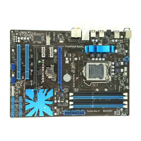
Page 18: Motherboard Layout
CPU_FAN PWR_FAN ATX12V MemOK! USB78 SPDIF_O2 USB56 LGA1156 USB34 LAN_USB12 CHA_FAN AUDIO PRI_IDE PCIEX1_1 VT6415 Realtek 8112L PCIEX16 PCIEX1_2 COM1 P7H55 PCIEX1_3 Intel ® Super PCI1 Lithium Cell CMOS Power PCI2 SATA4 SATA5 SATA6 VT1708S BIOS PCI3 USBPW9-12 SB_PWR CLRTC AAFP…
-
Page 19: Central Processing Unit (Cpu)
Contact your retailer immediately if the PnP cap is missing, or if you see any damage to the PnP cap/socket contacts/motherboard components. ASUS will shoulder the cost of repair only if the damage is shipment/transit-related. • Keep the cap after installing the motherboard. ASUS will process Return Merchandise Authorization (RMA) requests only if the motherboard comes with the cap on the LGA1156 socket.
-
Page 20
Lift the load lever in the direction of the arrow until the load plate is completely lifted. Load plate Remove the PnP cap from the CPU socket by lifting the tab only. PnP cap Cap tab Position the CPU over the socket, ensuring that the gold triangle is on the bottom-left corner of the socket, and CPU notches… -
Page 21
Close the load plate (A), and then push down the load lever (B), ensuring that the front edge of the load plate slides under the retention knob (C). Insert the load lever under the retention tab. ASUS P7H55 1-10… -
Page 22: Installing The Cpu Heatsink And Fan
1.6.2 Installing the CPU heatsink and fan The Intel LGA1156 processor requires a specially designed heatsink and fan assembly to ® ensure optimum thermal condition and performance. • When you buy a boxed Intel processor, the package includes the CPU fan and ®…
-
Page 23: Uninstalling The Cpu Heatsink And Fan
Connect the CPU fan cable to the connector on the motherboard labeled CPU_FAN. CPU_FAN P7H55 P7H55 CPU fan connector Do not forget to connect the CPU fan connector! Hardware monitoring errors can occur if you fail to plug this connector.
-
Page 24: System Memory
DDR2 DIMM socket. DDR3 modules are developed for better performance with less power consumption. The figure illustrates the location of the DDR3 DIMM sockets: Channel Sockets Channel A DIMM_A1 and DIMM_A2 Channel B DIMM_B1 and DIMM_B2 P7H55 P7H55 240-pin DDR3 DIMM sockets 1-13 Chapter 1: Product introduction…
-
Page 25: Memory Configurations
• Hyper DIMM support is subject to the physical characteristics of individual CPUs. • According to Intel spec definition, DDR3 1600+ is supported for one DIMM per channel only. ASUS exclusively provides two DDR3 1600+ DIMM support for each memory channel.
-
Page 26: Installing A Dimm
1.7.3 Installing a DIMM Ensure to unplug the power supply before adding or removing DIMMs or other system components. Failure to do so may cause severe damage to both the motherboard and the components. DIMM notch To install a DIMM Unlock a DIMM socket by pressing the retaining clip outward.
-
Page 27: Expansion Slots
PCI Express x16 slot This motherboard has a PCI Express 2.0 x16 slot that supports PCI Express x16 2.0 graphic cards complying with the PCI Express specifications. Refer to section 1.5.3 Motherboard layout for the location of the expansion slots. ASUS P7H55 1-16…
-
Page 28: Jumpers
Normal Clear RTC (Default) P7H55 Clear RTC RAM To erase the RTC RAM: 1. Turn OFF the computer and unplug the power cord. 2. Move the jumper cap from pins 1-2 (default) to pins 2-3. Keep the cap on pins 2-3 for about 5-10 seconds, then move the cap back to pins 1-2.
-
Page 29: Keyboard Power
P7H55 +5VSB (Default) P7H55 USB Device Wake Up • The USB device wake-up feature requires a power supply that can provide 500mA on the +5VSB lead for each USB port; otherwise, the system would not power up. • The total current consumed must NOT exceed the power supply capability (+5VSB) whether under normal condition or in sleep mode.
-
Page 30: Memok! Switch
• If the installed DIMMs still fail to boot after the whole tuning process, the DRAM_LED lights continuously. Replace the DIMMs with ones recommended in the Memory QVL (Qualified Vendors Lists) in this user manual or on the ASUS website at www.asus.com.
-
Page 31: Connectors
Side Speaker Out port (gray). This port connects the side speaker in an 8-channel audio configuration. Refer to the audio configuration table on the next page for the function of the audio ports in 2, 4, 6, or 8-channel configuration. ASUS P7H55 1-20…
-
Page 32: Internal Connectors
Legacy AC’97 pin definition compliant definition P7H55 Analog front panel connector • We recommend that you connect a high-definition front panel audio module to this connector to avail of the motherboard’s high-definition audio capability. • If you want to connect a high-definition front panel audio module to this connector, set the Front Panel Type item in the BIOS setup to [HD Audio].
-
Page 33
If any device jumper is set as “Cable-Select,” ensure that all other device jumpers have the same setting. Optical drive audio connector (4-pin CD) These connectors allow you to receive stereo audio input from sound sources such as a CD-ROM, TV tuner, or MPEG card. P7H55 P7H55 Internal audio connector ASUS P7H55 1-22… -
Page 34
• DO NOT forget to connect the 4-pin ATX +12V power plug. Otherwise, the system will not boot up. • If you are uncertain about the minimum power supply requirement for your system, refer to the Recommended Power Supply Wattage Calculator at http://support.asus. com/PowerSupplyCalculator/PSCalculator.aspx?SLanguage=en-us for details. USB connectors (10-1 pin USB910, USB1112) These connectors are for USB 2.0 ports. -
Page 35
These are not jumpers! Do not place jumper caps on the fan connectors! • Only the 4-pin CPU fan supports the ASUS Q-FAN feature. • The CPU_FAN connector supports a CPU fan of maximum 2A (24 W) fan power. -
Page 36
This connector is for a serial (COM) port. Connect the serial port module cable to this connector, then install the module to a slot opening at the back of the system chassis. COM1 PIN 1 P7H55 P7H55 Serial port (COM1) connector The COM module is purchased separately. 1-25 Chapter 1: Product introduction… -
Page 37: System Panel Connector
IDE_LED PWRSW RESET * Requires an ATX power supply P7H55 System panel connector • System power LED (2-pin PLED) This 2-pin connector is for the system power LED. Connect the chassis power LED cable to this connector. The system power LED lights up when you turn on the system power, and blinks when the system is in sleep mode.
-
Page 38: Software Support
The contents of the Support DVD are subject to change at any time without notice. Visit the ASUS website at www.asus.com for updates. To run the Support DVD Place the Support DVD to the optical drive.
-
Page 39: Chapter 2: Bios Information
BIOS in the future. Copy the original motherboard BIOS using the ASUS Update utility. 2.1.1 ASUS Update utility The ASUS Update is a utility that allows you to manage, save, and update the motherboard BIOS in Windows environment. ®…
-
Page 40: Asus Ez Flash 2
Follow the onscreen instructions to complete the updating process. 2.1.2 ASUS EZ Flash 2 The ASUS EZ Flash 2 feature allows you to update the BIOS without using an OS-based utility. Before you start using this utility, download the latest BIOS file from the ASUS website at www.asus.com.
-
Page 41: Asus Crashfree Bios
2.1.3 ASUS CrashFree BIOS The ASUS CrashFree BIOS is an auto recovery tool that allows you to restore the BIOS file when it fails or gets corrupted during the updating process. You can restore a corrupted BIOS file using the motherboard support DVD or a removable device that contains the updated BIOS file.
-
Page 42
Insert the USB flash drive with the latest BIOS file and BIOS Updater to the USB port. Boot your computer. When the ASUS Logo appears, press <F8> to show the BIOS Boot Device Select Menu. Insert the support DVD into the optical drive and select the optical drive as the boot device. -
Page 43: Updating The Bios File
ASUSTek BIOS Updater for DOS V1.00b [09/06/22] FLASH TYPE: MXIC 25L1605A Current ROM Update ROM BOARD: P7H55 BOARD: Unknown VER: 0302 VER: Unknown DATE: 12/28/2009 DATE: Unknown PATH: BIOS backup is done! Press any key to continue. Note Saving BIOS:…
-
Page 44: Bios Setup Program
• The BIOS setup screens shown in this section are for reference purposes only, and may not exactly match what you see on your screen. • Visit the ASUS website at www.asus.com to download the latest BIOS file for this motherboard.
-
Page 45: Bios Menu Screen
2.2.1 BIOS menu screen Menu items Menu bar Configuration fields General help BIOS SETUP UTILITY Main Ai Tweaker Advanced Power Boot Tools Exit Use [ENTER], [TAB] or System Time [12:56:38] [SHIFT-TAB] to select System Date [Thu 07/09/2009] a field. Language [English] Use [+] or [-] to SATA1…
-
Page 46: Submenu Items
:[Not Detected] SATA5 :[Not Detected] SATA6 :[Not Detected] Select Screen Storage Configuration Select Item System Information Change Field Select Field General Help Save and Exit Exit v02.61 (C)Copyright 1985-2009, American Megatrends, Inc. v02.61 (C)Copyright 1985-2009, American Megatrends, Inc. ASUS P7H55…
-
Page 47: System Time
2.3.1 System Time [xx:xx:xx] Allows you to set the system time. 2.3.2 System Date [Day xx/xx/xxxx] Allows you to set the system date. 2.3.3 SATA1~6 While entering Setup, the BIOS automatically detects the presence of SATA devices. There is a separate submenu for each SATA device. Select a device item then press <Enter> to display the SATA device information.
-
Page 48: System Information
This menu gives you an overview of the general system specifications. The BIOS automatically detects the items in this menu. BIOS Information Displays the auto-detected BIOS information Processor Displays the auto-detected CPU specification System Memory Displays the auto-detected system memory 2-10 ASUS P7H55…
-
Page 49: Ai Tweaker Menu
Ai Tweaker menu The Ai Tweaker menu items allow you to configure overclocking-related items. Be cautious when changing the settings of the Ai Tweaker menu items. Incorrect field values can cause the system to malfunction. The configuration options for this chapter vary depending on the CPU and DIMM model you installed on the motherboard.
-
Page 50: Xtreme Phase Full Power Mode
D.O.C.P. D.O.C.P. • When using DIMMs with afrequency higher than the Intel CPU spec, use this ASUS ® exclusive DRAM O.C. Profile function to overclock the DRAM. • Adjust BCLK frequency to obtain a better performance after applying the D.O.C.P.
-
Page 51: Dram Timing Control
The following two items appear only when you set the Ai Overclock Tuner item to [Manual], [D.O.C.P.] or [X.M.P.]. BCLK Frequency [XXX] Allows you to adjust the Internal Base Clock (BCLK). Use the <+> and <-> keys to adjust the value.
-
Page 52
Configuration options: [Auto] [2 DRAM Clock] – [14 DRAM Clock] DRAM READ to WRITE Delay(SR) [Auto] Configuration options: [Auto] [2 DRAM Clock] – [14 DRAM Clock] DRAM READ to READ Delay(DD) [Auto] Configuration options: [Auto] [2 DRAM Clock] – [9 DRAM Clock] 2-14 ASUS P7H55… -
Page 53
DRAM READ to READ Delay(DR) [Auto] Configuration options: [Auto] [2 DRAM Clock] – [9 DRAM Clock] DRAM READ to READ Delay(SR) [Auto] Configuration options: [Auto] [4 DRAM Clock] [6 DRAM Clock] DRAM WRITE to WRITE Delay(DD) [Auto] Configuration options: [Auto] [2 DRAM Clock] – [9 DRAM Clock] DRAM WRITE to WRITE Delay(DR) [Auto] Configuration options: [Auto] [2 DRAM Clock] –… -
Page 54
1.65V. Load-Line Calibration [Auto] [Auto] Automatic configuration. [Disabled] Follow Intel specifications. [Enabled] Improve CPU VDroop directly. PCIE Spread Spectrum [Disabled] [Auto] Automatic configuration. [Disabled] Enhances the PCIE overclocking ability. [Enabled] Sets to [Enabled] for EMI control. 2-16 ASUS P7H55… -
Page 55: Advanced Menu
Advanced menu The Advanced menu items allow you to change the settings for the CPU and other system devices. Be cautious when changing the settings of the Advanced menu items. Incorrect field values can cause the system to malfunction. BIOS SETUP UTILITY Main Ai Tweaker Advanced…
-
Page 56
This item appears only when you set the Intel(R) C-STATE Tech item to [Enabled]. We recommend that you set this item to [Auto] for BIOS to automatically detect the C-State mode supported by your CPU. Configuration options: [Auto] [C1] [C3] [C6] 2-18 ASUS P7H55… -
Page 57: Uncore Configuration
2.5.2 Uncore Configuration The North Bridge Configuration menu allows you to change the advanced chipset settings. Memory Remap Feature [Enabled] [Disabled] Do not allow remapping of memory. [Enabled] Allows for the segment of system memory that was previously overwritten by PCI devices to be remapped above the total physical memory.
-
Page 58: Pcipnp
[Auto] used for System ACPI 2.0 Support [Enabled] Suspend. ACPI APIC Support [Enabled] APM Configuration Hardware Monitor Select Screen ←→ Select Item ↑↓ Change Option General Help Save and Exit Exit v02.61 (C)Copyright 1985-2009, American Megatrends, Inc. 2-20 ASUS P7H55…
-
Page 59: Suspend Mode
2.6.1 Suspend Mode [Auto] Allows you to select the Advanced Configuration and Power Interface (ACPI) state to be used for system suspend. [S1 (POS) only] Sets the APCI suspend mode to S1/POS (Power On Suspend). [S3 only] Sets the APCI suspend mode to S3/STR (Suspend To RAM). [Auto] The system automatically configures the ACPI suspend mode.
-
Page 60: Hardware Monitor
Sets to [Silent] to minimize the fan speed for quiet CPU fan operation. [Turbo] Set to [Turbo] to achieve maximum CPU fan speed. Chassis Q-Fan Control [Disabled] [Disabled] Disables the Chassis Q-Fan control feature. [Enabled] Enables the Chassis Q-Fan control feature. 2-22 ASUS P7H55…
-
Page 61: Boot Menu
Configuration options: [Removable Dev.] [Hard Drive] [ATAPI CD-ROM] [Disabled] • To select the boot device during system startup, press <F8> when ASUS Logo appears. • To access Windows OS in Safe Mode, do any of the following: ®…
-
Page 62: Boot Settings Configuration
Enables or disables the full screen logo display feature. Configuration options: [Disabled] [Enabled] Set this item to [Enabled] to use the ASUS MyLogo2™ feature. AddOn ROM Display Mode [Force BIOS] Sets the display mode for option ROM. Configuration options: [Force BIOS] [Keep Current] Bootup Num-Lock [On] Selects the power-on state for the NumLock.
-
Page 63: Tools Menu
BIOS SETUP UTILITY Main Ai Tweaker Advanced Power Boot Tools Exit Tools Settings ASUS O.C. Profile AI NET 2 ASUS EZ Flash 2 Express Gate [Auto] Enter OS Timer [10 Seconds] Reset User Data [No] Chapter 2: BIOS information 2-25…
-
Page 64: Asus O.c. Profile
2.8.3 ASUS EZ Flash 2 Allows you to run ASUS EZ Flash 2. When you press <OK>, a confirmation message appears. Use the left/right arrow key to select between [Yes] or [No], then press <OK> to confirm your choice. See section 2.1.2 ASUS EZ Flash 2 for details.
-
Page 65: Exit Menu
enter the Express Gate. User data includes the Express Gate’s settings as well as any personal information stored by the web browser such as bookmarks, cookies, browsing history. This is useful in the rare case where corrupt settings prevent the Express Gate environment from launching properly.
-
Page 66
2-28 ASUS P7H55…
-
Драйверы
21
-
Инструкции по эксплуатации
3
Языки:

ASUS P7H55 инструкция по эксплуатации
(66 страниц)
- Языки:Английский
-
Тип:
PDF -
Размер:
3.88 MB -
Описание:
P7H55 user’s manual (English)
Просмотр

ASUS P7H55 инструкция по эксплуатации
(1 страница)
- Языки:Английский
-
Тип:
PDF -
Размер:
407.58 KB
Просмотр

ASUS P7H55 инструкция по эксплуатации
(71 страница)
- Языки:Французский
-
Тип:
PDF -
Размер:
4.04 MB -
Описание:
P7H55 user’s manual (French)
Просмотр
На NoDevice можно скачать инструкцию по эксплуатации для ASUS P7H55. Руководство пользователя необходимо для ознакомления с правилами установки и эксплуатации ASUS P7H55. Инструкции по использованию помогут правильно настроить ASUS P7H55, исправить ошибки и выявить неполадки.
Ваш электронный адрес не будет опубликован. Обязательные поля помечены * *
КОММЕНТАРИЙ *
Имя и фамилия
Эл. адрес
Cайт
Сохраните мое имя, адрес электронной почты и веб-сайт в этом браузере для следующего комментария.
Скачать файл PDF «ASUS P7H55 Руководство по эксплуатации» (3.88 Mb)
Популярность:
1254 просмотры
Подсчет страниц:
66 страницы
Тип файла:
Размер файла:
3.88 Mb
-
Asus P7H55 — page 1
Motherboard P7H55/USB3 …
-
Asus P7H55 — page 2
ii E5833 First Edition (V1) May 2010 Copyright © 2010 ASUST eK COMPUTER INC. All Rights Reserved. No part of this manual, including the products and software described in it, may be reproduced, transmitted, transcribed, stored in a retrieval system, or translated into any language in any form or by any means, except documentation kept by the purch …
-
Asus P7H55 — page 3
iii Contents Notices …………………………………………………………………………………………… vi Safety information …………………………………………………………………………. vii About this guide …………………………………………………………………………… viii P …
-
Asus P7H55 — page 4
iv Contents 2.1.1 ASUS Update ………………………………………………………… 2-1 2.1.2 ASUS EZ Flash 2 …………………………………………………… 2-2 2.1.3 ASUS CrashFree BIOS 3 utility ……………………………….. 2-3 2.2 BIOS setup program …………………………………………………… …
-
Asus P7H55 — page 5
v Contents 2.5.2 Uncore Conguration ……………………………………………. 2-17 2.5.3 Onboard Device Conguration ……………………………….. 2-17 2.5.4 USB Conguration ……………………………………………….. 2-17 2.5.5 PCIPnP ………………………………………………………………. …
-
Asus P7H55 — page 6
vi Notices Federal Communications Commission Statement This device complies with Part 15 of the FCC Rules. Operation is subject to the following two conditions: • This device may not cause harmful interference, and • This device must accept any interference received including interference that may cause undesired operation. This equipment has b …
-
Asus P7H55 — page 7
vii Safety information Electrical safety • T o prevent electrical shock hazard, disconnect the power cable from the electrical outlet before relocating the system. • When adding or removing devices to or from the system, ensure that the power cables for the devices are unplugged before the signal cables are connected. If possible, disconnect al …
-
Asus P7H55 — page 8
viii About this guide This user guide contains the information you need when installing and conguring the motherboard. How this guide is organized This guide contains the following parts: • Chapter 1: Product introduction This chapter describes the features of the motherboard and the new technology it supports. • Chapter 2: BIOS information …
-
Asus P7H55 — page 9
ix P7H55/USB3 specications summary (continued on the next page) CPU LGA1 156 socket for Intel ® Core™ i7 / Core™ i5 / Core™ i3 / Pentium™ Processors Supports Intel ® T urbo Boost T echnology * The Intel ® Turbo Boost T echnology support depends on the CPU types. ** Refer to www .asus.com for Intel CPU support list Chipset Intel ® H55 …
-
Asus P7H55 — page 10
x P7H55/USB3 specications summary ASUS Unique Features Hybrid Processer: — ASUS T urboV EVO, T urboV , Auto Tuning Hybrid Switch: — T urbo Key II Hybrid OS: — Express Gate ASUS Exclusive Features: — MemOK! — ASUS EPU ASUS Quiet Thermal Solution: — ASUS Fanless Design: Stylish Heatsink Solution, MOS Heatsink — ASUS Fan Xpert ASUS EZ DIY : — ASUS …
-
Asus P7H55 — page 11
xi P7H55/USB3 specications summary Internal I/O Connectors 2 x USB connectors support additional 4 USB ports 6 x SA T A 3Gb/s connectors 1 x 4-pin CPU Fan connector 1 x 3-pin Chassis Fan connector 1 x 3-pin Power Fan connector 1 x Front panel audio connector 1 x S/PDIF Out header 1 x CD audio in 1 x 24-pin EA TX Power connector 1 x 4-pin A TX 12 …
-
Asus P7H55 — page 12
xii …
-
Asus P7H55 — page 13
ASUS P7H55/USB3 1-1 If any of the items is damaged or missing, contact your retailer . 1.1 Before you proceed T ake note of the following precautions before you install motherboard components or change any motherboard settings. • Unplug the power cord from the wall socket before touching any component. • Before handling components, use a ground …
-
Asus P7H55 — page 14
1-2 Chapter 1: Product introduction 1.2.2 Layout contents 1.2 Motherboard overview 1.2.1 Motherboard layout Place six screws into the holes indicated by circles to secure the motherboard to the chassis. DO NOT overtighten the screws! Doing so can damage the motherboard. Place this side towards the rear of the chassis. Ensure that you install the mo …
-
Asus P7H55 — page 15
ASUS P7H55/USB3 1-3 1.3 Central Processing Unit (CPU) The motherboard comes with a surface mount LGA1 156 socket designed for the Intel ® 1.3.1 Installing the CPU T o install a CPU: 1. Locate the CPU socket on the motherboard. Ensure that all power cables are unplugged before installing the CPU. • Upon purchase of the motherboard, ensure that th …
-
Asus P7H55 — page 16
1-4 Chapter 1: Product introduction 3. Lift the load lever in the direction of the arrow until the load plate is completely lifted. Load plate 4. Remove the PnP cap from the CPU socket by lifting the tab only . The CPU ts in only one correct orientation. DO NOT force the CPU into the socket to prevent bending the connectors on the socket and dam …
-
Asus P7H55 — page 17
ASUS P7H55/USB3 1-5 7. Close the load plate (A), and then push down the load lever (B), ensuring that the front edge of the load plate slides under the retention knob (C). B A C 8. Insert the load lever under the retention tab. 6. Apply some Thermal Interface Material to the exposed area of the CPU that the heatsink will be in contact with, ensurin …
-
Asus P7H55 — page 18
1-6 Chapter 1: Product introduction 1.3.2 Installing the CPU heatsink and fan The Intel ® LGA1 156 processor requires a specially designed heatsink and fan assembly to ensure optimum thermal condition and performance. • When you buy a boxed Intel ® processor , the package includes the CPU fan and heatsink assembly . If you buy a CPU separately …
-
Asus P7H55 — page 19
ASUS P7H55/USB3 1-7 3. Connect the CPU fan cable to the connector on the motherboard labeled CPU_F AN. DO NOT forget to connect the CPU fan connector! Hardware monitoring errors can occur if you fail to plug this connector . 1.3.3 Uninstalling the CPU heatsink and fan T o uninstall the CPU heatsink and fan: 1. Disconnect the CPU fan cable from the …
-
Asus P7H55 — page 20
1-8 Chapter 1: Product introduction 1.4 System memory 1.4.1 Overview The motherboard comes with four Double Data Rate 3 (DDR3) Dual Inline Memory Modules (DIMM) sockets. A DDR3 module has the same physical dimensions as a DDR2 DIMM but is notched differently to prevent installation on a DDR2 DIMM socket. DDR3 modules are developed for better perfor …
-
Asus P7H55 — page 21
ASUS P7H55/USB3 1-9 1.4.2 Memory congurations Y ou may install 1GB, 2GB and 4GB unbuffered and non-ECC DDR3 DIMMs into the DIMM sockets. • The default memory operation frequency is dependent on its Serial Presence Detect (SPD), which is the standard way of accessing information from a memory module. Under the default state, some memory modules …
-
Asus P7H55 — page 22
1-10 Chapter 1: Product introduction P7H55/USB3 Motherboard Qualied V endors Lists (QVL) DDR3-2133MHz capability for Intel L ynneld CPU V endor Part No. Size SS/DS Chip Brand Chip NO. Timing V oltage DIMM socket support (Optional) A* B* C* GEIL GE34GB2133C9DC (XMP) 4GB (2 x 2GB) DS — — 9-9-9-28 1.65 • • P7H55/USB3 Motherboard Qualied V …
-
Asus P7H55 — page 23
ASUS P7H55/USB3 1-1 1 P7H55/USB3 Motherboard Qualied V endors Lists (QVL) DDR3-1600MHz capability for Intel Clarkdale CPU V endor Part No. Size SS/ DS Chip Brand Chip NO. Timing Dimm(Bios) V oltage DIMM socket support (Optional) A* B* C* A-DA TA AD31600G001GMU 1GB SS — — 9-9-9-24 1.65~1.85 • • A-DA TA AX3U1600GB1G9-AG 2GB(2 x 1GB) SS — — 9-9 …
-
Asus P7H55 — page 24
1-12 Chapter 1: Product introduction P7H55/USB3 Motherboard Qualied V endors Lists (QVL) DDR3-1333MHz capability for Intel L ynneld CPU V endor Part No. Size SS/DS Chip Brand Chip NO. Timing V oltage DIMM socket support (Optional) A* B* C* A-DA TA AD3133301GOU 1GB SS A-DAT A AD30908C8D-15IG — — • • • A-DA TA AD31333002GOU 2GB DS A-DAT A …
-
Asus P7H55 — page 25
ASUS P7H55/USB3 1-13 P7H55/USB3 Motherboard Qualied V endors Lists (QVL) DDR3-1333MHz capability for Intel Clarkdale CPU V endor Part No. Size SS/ DS Chip Brand Chip NO. Timing Dimm(Bios) V oltage DIMM socket support (Optional) A* B* C* A-DA TA AD3133301GOU 1GB SS A-DAT A AD30908C8D-15IG — — • • A-DA TA AX3U1333PB2G7-2P 4GB(2 x 2GB) DS — — 7 …
-
Asus P7H55 — page 26
1-14 Chapter 1: Product introduction P7H55/USB3 Motherboard Qualied V endors Lists (QVL) DDR3-1333MHz capability for Intel Clarkdale CPU (continued) P7H55/USB3 Motherboard Qualied V endors Lists (QVL) DDR3-1067MHz capability for Intel L ynneld CPU V endor Part No. Size SS/DS Chip Brand Chip NO. Timing Voltage DIMM socket support (Optional) …
-
Asus P7H55 — page 27
ASUS P7H55/USB3 1-15 V endor Part No. Size SS/ DS Chip Brand Chip NO. Timing Dimm(Bios) V oltage DIMM socket support (Optional) A* B* C* Crucial CT12864BA1067.8FF 1GB SS MICRON D9KPT 7 — • • • Crucial CT12864BA1067.8SFD 1GB SS MICRON D9JNL 7 — • • • Crucial CT12872BA1067.9FF 1GB SS MICRON D9KPT(ECC) 7 — • • • Crucial CT25664BA1067 …
-
Asus P7H55 — page 28
1-16 Chapter 1: Product introduction 1.4.4 Removing a DIMM 1. Simultaneously press the retaining clips outward to unlock the DIMM. 2. Remove the DIMM from the socket. 1.4.3 Installing a DIMM 3. Hold the DIMM by both of its ends, then insert the DIMM vertically into the socket. Apply force to both ends of the DIMM simultaneously until the retaining …
-
Asus P7H55 — page 29
ASUS P7H55/USB3 1-17 1.5 Expansion slot In the future, you may need to install expansion cards. The following sub-sections describe the slot and the expansion cards that it supports. Unplug the power cord before adding or removing expansion cards. Failure to do so may cause you physical injury and damage motherboard components. 1.5.1 Installing an …
-
Asus P7H55 — page 30
1-18 Chapter 1: Product introduction 1.6 Jumpers Clear RTC RAM (3-pin CLRTC) This jumper allows you to clear the Real T ime Clock (RTC) RAM in CMOS. Y ou can clear the CMOS memory of date, time, and system setup parameters by erasing the CMOS RTC RAM data. The onboard button cell battery powers the RAM data in CMOS, which include system setup infor …
-
Asus P7H55 — page 31
ASUS P7H55/USB3 1-19 • The DRAM_LED also lights when the DIMM is not properly installed. T urn off the system and reinstall the DIMM before using the MemOK! function. • Press the MemOK! switch under Windows™ OS environment will reboot the computer and start memory tuning. • During the tuning process, the system loads and tests failsafe memo …
-
Asus P7H55 — page 32
1-20 Chapter 1: Product introduction 2. T urbo Key II switch This switch allows you to auto-tune your CPU to enhance the system performance. • The LED near the T urbo Key II switch lights when the switch setting is turned to Enable . • If you clear the CMOS or load the BIOS setup defaults, the related overclocking items in the BIOS menu follow …
-
Asus P7H55 — page 33
ASUS P7H55/USB3 1-21 1.8 Connectors 1.8.1 Rear panel connectors 1. PS/2 mouse port (green). This port is for a PS/2 mouse. 2. LAN (RJ-45) port. This port allows Gigabit connection to a Local Area Network (LAN) through a network hub. Refer to the table on the next page for the LAN port LED indicators. ACT/LINK LED SPEED LED Status Description Status …
-
Asus P7H55 — page 34
1-22 Chapter 1: Product introduction • For a fully congured system, we recommend that you use a power supply unit (PSU) that complies with A TX 12 V Specication 2.0 (or later version) and provides a minimum power of 350 W . • Do not forget to connect the 4-pin EA TX12V power plug. Otherwise, the system will not boot. • If you are uncert …
-
Asus P7H55 — page 35
ASUS P7H55/USB3 1-23 Do not forget to connect the fan cables to the fan connectors. Insufcient air ow inside the system may damage the motherboard components. These are not jumpers! Do not place jumper caps on the fan connectors! 2. CPU, chassis, and power fan connectors (4-pin CPU_F AN, 3-pin CHA_F AN, 3-pin PWR_F AN) The fan connectors supp …
-
Asus P7H55 — page 36
1-24 Chapter 1: Product introduction 4. Front panel audio connector (10-1 pin AAFP) This connector is for a chassis-mounted front panel audio I/O module that supports either HD Audio or legacy AC`97 audio standard. Connect one end of the front panel audio I/O module cable to this connector . • We rec ommend that you co nnec t a high -denit ion …
-
Asus P7H55 — page 37
ASUS P7H55/USB3 1-25 6. Intel ® H55 Serial A T A connectors (7-pin SA T A1-6) These connectors are for the Serial A T A signal cables for Serial A T A hard disk drives and optical disc drives. • These connectors are set to Standard IDE mode by default. In Standard IDE mode, you can connect Serial A T A boot/data hard disk drives to these connect …
-
Asus P7H55 — page 38
1-26 Chapter 1: Product introduction 7. System panel connector (20-8 pin P ANEL) This connector supports several chassis-mounted functions. • System power LED (2-pin PLED) This 2-pin connector is for the system power LED. Connect the chassis power LED cable to this connector . The system power LED lights up when you turn on the system power , and …
-
Asus P7H55 — page 39
ASUS P7H55/USB3 1-27 8. USB connectors (10-1 pin USB910, USB1 1 12) These connectors are for USB 2.0 ports. Connect the USB module cable to any of these connectors, then install the module to a slot opening at the back of the system chassis. These USB connectors comply with USB 2.0 specication that supports up to 480 Mbps connection speed. Y ou …
-
Asus P7H55 — page 40
1-28 Chapter 1: Product introduction The Drivers menu shows the available device drivers if the system detects installed devices. Install the necessary drivers to use the devices. The Utilities menu shows the applications and other software that the motherboard supports. The Make disk menu contains items to create the RAID/AHCI driver disk. The Man …
-
Asus P7H55 — page 41
ASUS P7H55/USB3 2-1 Save a copy of the original motherboard BIOS le to a USB ash disk in case you need to restore the BIOS in the future. Copy the original motherboard BIOS using the ASUS Update utility . • ASUS Update requires an Internet connection either through a network or an Internet Service Provider (ISP). • This utility is availab …
-
Asus P7H55 — page 42
2-2 Chapter 2: BIOS information 2.1.2 ASUS EZ Flash 2 The ASUS EZ Flash 2 feature allows you to update the BIOS without using an OS-based utility . Before you start using this utility , download the latest BIOS le from the ASUS website at www .asus.com. T o update the BIOS using EZ Flash 2: 1. Insert the USB ash disk that contains the latest …
-
Asus P7H55 — page 43
ASUS P7H55/USB3 2-3 2. When the correct BIOS le is found, EZ Flash 2 performs the BIOS update process and automatically reboots the system when done. • Only a USB ash disk with F A T 32/16 format and single partition can support the ASUS EZ Flash 2 utility . • Do not shut down or reset the system while updating the BIOS to prevent system …
-
Asus P7H55 — page 44
2-4 Chapter 2: BIOS information 2.2 BIOS setup program Use the BIOS Setup program to update the BIOS or congure its parameters. The BIOS screens include navigation keys and brief online help to guide you in using the BIOS Setup program. Entering BIOS Setup at startup T o enter BIOS Setup at startup: • Press <Delete> during the Power-On S …
-
Asus P7H55 — page 45
ASUS P7H55/USB3 2-5 2.3.1 SA T A 1-6 While entering Setup, the BIOS automatically detects the presence of IDE/SA T A devices. There is a separate submenu for each IDE/SA T A device. Select a device item then press <Enter> to display the SA T A device information. The BIOS automatically detects the values opposite the dimmed items (Device, V e …
-
Asus P7H55 — page 46
2-6 Chapter 2: BIOS information 32Bit Data T ransfer [Enabled] [Enabled] Sets the IDE controller to combine two 16-bit reads from the hard disk into a single 32-bit double word transfer to the processor . This makes more efcient use of the PCI bus as fewer transactions are needed for the transfer of a particular amount of data. [Disabled] Disabl …
-
Asus P7H55 — page 47
ASUS P7H55/USB3 2-7 2.3.4 System Information This menu gives you an overview of the general system specications. The BIOS automatically detects the BIOS information, CPU specication, and system memory in this menu. …
-
Asus P7H55 — page 48
2-8 Chapter 2: BIOS information 2.4 Ai T weaker menu The Ai T weaker menu items allow you to congure overclocking-related items. Be cautious when changing the settings of the Ai T weaker menu items. Incorrect eld values can cause the system to malfunction. The conguration options for this chapter vary depending on the CPU and DIMM model yo …
-
Asus P7H55 — page 49
ASUS P7H55/USB3 2-9 2.4.2 Ai Overclock T uner [Auto] Allows selection of CPU overclocking options to achieve desired CPU internal frequency . Select either one of the preset overclocking conguration options: Manual Allows you to individually set overclocking parameters. Auto Loads the optimal settings for the system. D.O.C.P Overclocks DRAM freq …
-
Asus P7H55 — page 50
2-10 Chapter 2: BIOS information 2.4.4 Intel(R) SpeedStep(TM) T ech [Enabled] When set to [Disabled], the CPU runs at its default speed. When set to [Enabled], the CPU speed is controlled by the operating system. Conguration options: [Disabled] [Enabled] 2.4.5 Intel(R) T urboMode T ech [Enabled] This item appears only if you set the CPU Ratio Se …
-
Asus P7H55 — page 51
ASUS P7H55/USB3 2-1 1 2.4.10 OC T uner [T urbo Prole] OC T uner automatically overclocks the frequency and voltage of CPU and DRAM. Choose [Good Performance] or [Better Performance] as a stable setting for daily use. Choose [T urbo Prole] as an advanced overclocking setting for special purposes. Conguration options: [Good Performance] [Bet …
-
Asus P7H55 — page 52
2-12 Chapter 2: BIOS information FOUR ACT WIN T ime [Auto] Conguration options: [Auto] [1 DRAM Clock] – [63 DRAM Clock] Back-T o-Back CAS# Delay [Auto] Conguration options: [Auto] [4 DRAM Clock] – [32 DRAM Clock] 2nd Information: 2N-44-0 The values vary depending on your settings of the following sub-items: T iming Mode [Auto] Congurat …
-
Asus P7H55 — page 53
ASUS P7H55/USB3 2-13 2.4.13 CPU Differential Amplitude [Auto] Different AMP might enhance BCLK overclocking ability . Conguration options: [Auto] [700mV] [800mV] [900mV] [1000mV] 2.4.14 CPU Clock Skew [Auto] Adjusting this item may help enhancing BCLK overclocking ability . Y ou may need to adjust the CPU Clock Skew item at the same time. Con …
-
Asus P7H55 — page 54
2-14 Chapter 2: BIOS information 2.4.18 CPU PLL V oltage [Auto] Allows you to set the CPU PLL voltage. The values range from 1.8V to 2.5V with a 0.0125V interval. 2.4.19 PCH V oltage [Auto] Allows you to set the Platform Controller Hub voltage. The values range from 1.05V to 1.5V with a 0.0125V interval. • The values of the IMC V oltage , DRAM V …
-
Asus P7H55 — page 55
ASUS P7H55/USB3 2-15 2.5 Advanced menu The Advanced menu items allow you to change the settings for the CPU and other system devices. Be cautious when changing the settings of the Advanced menu items. Incorrect eld values can cause the system to malfunction. v02.61 (C)Copyright 1985-2010, American Megatrends, Inc. BIOS SETUP UTILITY Main Ai Twea …
-
Asus P7H55 — page 56
2-16 Chapter 2: BIOS information Max CPUID V alue Limit [Disabled] [Enabled] Allows legacy operating systems to boot even without support for CPUs with extended CPUID functions. [Disabled] Disables this function. Intel(R) Virtualization T ech [Enabled] [Enabled] Allows a hardware platform to run multiple operating systems separately and simultaneou …
-
Asus P7H55 — page 57
ASUS P7H55/USB3 2-17 C State package limit setting [Auto] This item appears only when you set the Intel(R) C-ST A TE T ech item to [Enabled]. We recommend that you set this item to [Auto] for BIOS to automatically detect the C-State mode supported by your CPU. Conguration options: [Auto] [C1] [C3] [C6] 2.5.2 Uncore Conguration The Uncore Con? …
-
Asus P7H55 — page 58
2-18 Chapter 2: BIOS information USB Functions [Enabled] [Enabled] Enables the USB Host Controllers. [Disabled] Disables the controllers. The following items appear only when you set USB Support to [Enabled]. Legacy USB Support [Auto] [Disabled] Disables the function. [Enabled] Enables the support for USB devices on legacy operating systems (OS). [ …
-
Asus P7H55 — page 59
ASUS P7H55/USB3 2-19 2.6 Power menu The Power menu items allow you to change the settings for the Advanced Power Management (APM). Select an item then press <Enter> to display the conguration options. v02.61 (C)Copyright 1985-2010, American Megatrends, Inc. BIOS SETUP UTILITY Main Ai Tweaker Advanced Power Boot Tools Exit Select the ACPI s …
-
Asus P7H55 — page 60
2-20 Chapter 2: BIOS information 2.6.6 APM Conguration Restore On AC Power Loss [Power Off] [Power Off] The system goes into off state after an AC power loss. [Power On] The system goes into on state after an AC power loss. [Last State] The system goes into either off or on state, whatever the system state was before the AC power loss. Power On …
-
Asus P7H55 — page 61
ASUS P7H55/USB3 2-21 2.6.7 Hardware Monitor CPU/MB T emperature [xxx�C/xxx�F] [xxx�C/xxx�F] The onboard hardware monitor automatically detects and displays the CPU and motherboard temperatures. Select Ignored if you do not wish to display the detected temperatures. CPU Fan Speed [xxxxRPM] or [Ignored] / [N/A] Chassis Fan 1 Speed [xxxxRPM] o …
-
Asus P7H55 — page 62
2-22 Chapter 2: BIOS information 2.7 Boot menu The Boot menu items allow you to change the system boot options. Select an item then press <Enter> to display the submenu. v02.61 (C)Copyright 1985-2010, American Megatrends, Inc. BIOS SETUP UTILITY Main Ai Tweaker Advanced Power Boot Tools Exit Species the Boot Device Priority sequence. A vir …
-
Asus P7H55 — page 63
ASUS P7H55/USB3 2-23 Full Screen Logo [Enabled] [Disabled] Disables the full screen logo display feature. [Enabled] Enables the full screen logo display feature. Set this item to [Enabled] to use the ASUS MyLogo 2™ feature. AddOn ROM Display Mode [Force BIOS] [Force BIOS] The third-party ROM messages will be forced to display during the boot sequ …
-
Asus P7H55 — page 64
2-24 Chapter 2: BIOS information After you have set a supervisor password, the other items appear to allow you to change other security settings. User Access Level [Full Access] This item allows you to select the access restriction to the Setup items. [No Access] Prevents user access to the Setup utility . [View Only] Allows access but does not all …
-
Asus P7H55 — page 65
ASUS P7H55/USB3 2-25 2.8 T ools menu The T ools menu items allow you to congure options for special functions. Select an item then press <Enter> to display the submenu. v02.61 (C)Copyright 1985-2010, American Megatrends, Inc. BIOS SETUP UTILITY Main Ai Tweaker Advanced Power Boot Tools Exit ASUS O.C. Prole AI NET 2 ASUS EZ Flash 2 Expre …
-
Asus P7H55 — page 66
2-26 Chapter 2: BIOS information 2.8.3 ASUS EZ Flash 2 Allows you to run ASUS EZ Flash 2. When you press <OK> , a conrmation message appears. Use the left/right arrow key to select between [Y es] or [No] , then press <OK> to conrm your choice. 2.8.4 Express Gate [Auto] Allows you to enable or disable the ASUS Express Gate feature. …
-
Asus P7H55 — page 67
ASUS P7H55/USB3 2-27 2.9 Exit menu The Exit menu items allow you to load the optimal or failsafe default values for the BIOS items, and save or discard your changes to the BIOS items. Pressing <Esc> does not immediately exit this menu. Select one of the options from this menu or <F10> from the legend bar to exit. Exit & Save Changes …
-
Asus P7H55 — page 68
2-28 Chapter 2: BIOS information …
-
Asus P7H55 — page 69
ASUS contact information ASUST eK COMPUTER INC. Address 15 Li-T e Road, Peitou, T aipei, T aiwan 1 1259 T elephone +886-2-2894-3447 Fax +886-2-2890-7798 E-mail info@asus.com.tw Web site www .asus.com.tw T echnical Support T elephone +86-21-3842991 1 Online support support.asus.com ASUS COMPUTER INTERNA TIONAL (America) Address 800 Corporate Way , F …
-
Asus P7H55 — page 70
EC Declaration of Conformity We, the undersigned, Manufacturer: ASUSTek COMPUTER INC. Address, City: No. 150, LI-TE RD., PEITOU, TAIPEI 112, TAIWAN R.O.C. Country: TAIWAN Authorized representative in Europe: ASUS C OMPUTER GmbH Address, City: HARKORT STR. 21-23, 40880 RATINGEN Country: GERMANY declare the following apparatus: Product name : Motherb …