-
Contents
-
Table of Contents
-
Bookmarks
Quick Links
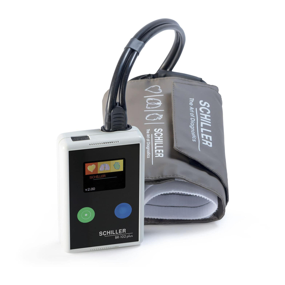
BR-102 PLUS
BR-102 PLUS PWA
24/48 Hour Ambulatory Blood Pressure Recorder
User Guide
Related Manuals for Schiller BR-102 PLUS
Summary of Contents for Schiller BR-102 PLUS
-
Page 1
BR-102 PLUS BR-102 PLUS PWA 24/48 Hour Ambulatory Blood Pressure Recorder User Guide… -
Page 2
Switzerland www.schiller.ch BR-102 plus / BR-102 plus PWA bears the CE-0123 mark (Notified Body TÜV-SÜD Produkte Ser- vice GmbH, Ridlerstr. 65, 80339 Munich, Germany), indicating its compliance with the essential re- quirements of the Annex I of the Medical Device Directive 93/42/EE regarding safety, functionality and labelling. -
Page 3: Table Of Contents
Safety Symbols and Pictograms ……11 1.11.1 Symbols used in this Document ……….. 11 1.11.2 Symbols on the Device, Batteries, and Accessories …. 11 Introduction ……….13 BR-102 plus / BR-102 plus PWA ……. 14 2.1.1 BR-102plus…………….14 2.1.2 BR-102 plus PWA…………..14 ®…
-
Page 4
Changing the Batteries During a 48 Hr Recording ….38 3.4.5 Stopping the Recording …………39 3.4.6 Displaying a Recording on the BR-102 plus ……39 3.4.7 Uploading the Recording to the medilogDARWIN2 ….40 Patient Information ………41 General …………… 42 Taking an Extra Measurement…….. -
Page 5
BR-102 plus / BR-102 plus PWA User Guide General Accessories……….63 Cuff and Cuff Accessories ……..64 BR-102 plus PWA ……..65 Overview …………..65 Measurements …………65 Display of Pulse Wave Analysis ……. 65 Method ……………. 66 Patient Diary ……….. 67 10.1… -
Page 6
BR-102 plus / BR-102 plus PWA Page 6… -
Page 7: Safety Notes
Further, with each measurement, the PWA data will be saved for subsequent external assessments. The BR-102 plus / BR-102 plus PWA can be used for adults and children (3 years old onwards) of both sexes and all ethnic origins.
-
Page 8: Contraindications
BR-102 plus / BR-102 plus PWA Contraindications 1.3 Contraindications The BR-102 plus / BR-102 plus PWA has not been designed for, and must not be used for the following patients: – neonates and children under the age of 3.
-
Page 9: Maintenance
Connecting the unit to a PC with defective cables may constitute a danger to life. Therefore: – Do not connect the BR-102 plus / BR-102 plus PWA to any PC if the earth connection is suspect or if the mains lead is damaged or suspected of being damaged.
-
Page 10: Operation With Other Devices
IEC/EN 60601-1. If in doubt, consult the technical service department or your local representative. The BR-102 plus / BR-102 plus PWA is safe during defibrillation. However, as a safety precaution remove the cable assembly between the recorder and the PC and when possible, remove the BR-102 plus from the patient before defibrillation.
-
Page 11: Safety Symbols And Pictograms
Equipment/components and accessories no longer required must be disposed of in a municipally approved collection point or recycling centre. Alternatively, you can return the equipment to your supplier or SCHILLER AG for disposal. Improper disposal can harm the environment and human health. Page 11…
-
Page 12
Safety Notes BR-102 plus / BR-102 plus PWA 1.11 Safety Symbols and Pictograms BR-102 plus / BR-102 plus PWA battery type 2 x AA 1.2 V / 2700 mAh, NiMH. Use NiMH charger only. NiMH NiMH Do not disassemble, mutilate, incinerate, or heat. Do not short circuit a battery. -
Page 13: Introduction
Safety Symbols and Pictograms 1.11 2 Introduction The SCHILLER BR-102 plus / BR-102 plus PWA is an Ambulatory Blood Pressure Recorder used for single and long-term recordings. The device can take up to 100 measurements over a 24 hour recording period, and up to 200 measurements over a 48 hour recording period.
-
Page 14: Br-102 Plus / Br-102 Plus Pwa
The recorders are available as follows: 2.1.1 BR-102plus The Standard BR-102 plus is identified by the black front casing. There are two measurement methods available as follows: • Option 1 employs the auscultatory (Riva-Rocci, Korotkoff) method of measurement, with an oscillometric method as back-up. This means that when a clear measurement cannot be obtained with the auscultatory method, the oscillometric value is used.
-
Page 15: The Medilog Darwin2 Program
63). 2.3 Inserting/Changing the Batteries Use NiMH rechargeable batteries supplied or recommended by SCHILLER. Full capacity of new NIMH batteries are only reached after three charge/discharge cycles. Eneloop Pro NiMH rechargeable batteries (Panasonic 2450 mA) or Energizer Ultimate Lithium batteries (ENERGIZER L91-FR6) can also be used.
-
Page 16: Connecting The Pressure Hose And Microphone
/ BR-102 plus PWA by gently pressing until the connector clicks in place. If the version is with a microphone (c), the plug is combined with the hose and the assembly is inserted into BR-102 plus / BR-102 plus PWA at the same time.
-
Page 17: Main Components Of The Device
Introduction BR-102 plus / BR-102 plus PWA User Guide Main Components of the Device 2.5 Main Components of the Device 05:16PM NEW RECORD LAST RECORD SINGLE MEAS. SYSTEM NEXT SCHILLER BR-102plus (a) USB cable connection (b) OLED display (c) Loudspeaker…
-
Page 18: Operating And Display Elements
Main Components of the Device 2.5.1 Operating and Display Elements Menu option selection and control of the BR-102 plus / BR-102 plus PWA is with two function keys. The green and blue function information boxes at the bottom of the screen indicate the function…
-
Page 19: Switching Off
Introduction BR-102 plus / BR-102 plus PWA User Guide Main Components of the Device 2.5.3 Switching Off With the main menu displayed and the cursor at any position, press and hold the Green control button for 4 seconds. When the button is released, the device is switched off.
-
Page 20: Battery Status For Nimh Rechargeable Batteries
The battery status display is a guide to battery capacity when using NiMH rechargeable batteries supplied or recommended by SCHILLER. If Energizer Ultimate Lithium Batteries are used, a different battery symbol is displayed (see next page). The battery symbol in the upper right of the screen, indicates the Full battery status.
-
Page 21: Battery Display For Energizer Ultimate Lithium Battery
Introduction BR-102 plus / BR-102 plus PWA User Guide Main Components of the Device 2.5.5 Battery Display for Energizer Ultimate Lithium Bat- tery If Energizer Ultimate Lithium batteries are used, the battery status display is shown blue and always ‘full’. This is because the voltage hysteresis curve for these types of battery is not linear and the device cannot accurately determine battery capacity.
-
Page 22: Menu Structure
Introduction BR-102 plus / BR-102 plus PWA Menu Structure 2.6 Menu Structure The menus are selected with the green function key (Next). A selected menu is opened with the blue function key (OK) and values selected with the blue function key (Change). Depending on the selected menu, the button functions will change.
-
Page 23: Menu Overview
Introduction BR-102 plus / BR-102 plus PWA User Guide Menu Structure 2.6.1 Menu Overview Sub Menu Main Menu Value/Info Value/Info Value/Info Menu 1 Menu 3 Defines the RECORD Patient Adult / Child — Maximum initial pressure for adult is recording…
-
Page 24
Introduction BR-102 plus / BR-102 plus PWA Menu Structure Sub Menu Main Menu Value/Info Value/Info Value/Info Menu 1 Menu 3 Plays recorded Play Voice patient identifica- Stop Stop Playing Voice. tion. Yes / No — Confirm Press either of the two Recording start. -
Page 25
Introduction BR-102 plus / BR-102 plus PWA User Guide Menu Structure Sub Menu Main Menu Value/Info Value/Info Value/Info Menu 1 Menu 3 Measurement is displayed (or an error message is given). Measurement Press OK again to return to the previous menu. -
Page 26: Bp Recording
BP recording BR-102 plus / BR-102 plus PWA Safety 3 BP recording 3.1 Safety Danger of unnoticed necrosis especially in patients with decreased pain sensitivity (due to medication), or with older patients with decreased blood circulation of the extremities. Only carry out long-term measurement with these patients under constant medical supervision.
-
Page 27
If the unit gets wet accidentally, switch off and dry with a cloth. If the unit is accidentally immersed in liquid, remove the batteries and return to SCHILLER for checking. A list of BR-102 plus error messages is given in the Maintenance section (see Error Messages, page 58). Page 27… -
Page 28: Applying The Cuff
BR-102 plus / BR-102 plus PWA Applying the Cuff 3.2 Applying the Cuff The BR-102 plus is supplied with one of two cuff types. Both are applied in the same way. The instructions detailed here give general guidelines and apply to both types of cuffs: 1.
-
Page 29
User Guide Applying the Cuff 8. Secure BR-102 plus / BR-102 plus PWA to the right or left side of the patient for preference using the holding pouch and belt – Ensure that there is enough slack not to strain the hose when the patient moves. -
Page 30: Cuff Type With D-Ring
BP recording BR-102 plus / BR-102 plus PWA Applying the Cuff 3.2.1 Cuff Type with D-ring There are three sizes available for the cuff with D-ring: To fit arm size Midpoint arm circumference Cuff designation [cm] 18 — 26 S (Small adult, Child)
-
Page 31: Patient Comfort Sleeve
BP recording BR-102 plus / BR-102 plus PWA User Guide Applying the Cuff 3.2.3 Patient Comfort Sleeve If the Patient comfort sleeve is to be used, the sleeve can be positioned on the patients arm and then the cuff applied. Alternatively attach the sleeve to the cuff with the velcro strip before applying to the patient and then apply the cuff and sleeve together to the patient.
-
Page 32: Securing The Cuff With The Fixation Pad
BP recording BR-102 plus / BR-102 plus PWA Applying the Cuff 3.2.5 Securing the Cuff with the Fixation Pad A velcro cuff fixing pad is a standard accessory that‘s available to help secure the cuff from dislodging during long term measurement.
-
Page 33: Single Measurement
BP recording BR-102 plus / BR-102 plus PWA User Guide Single Measurement 3.3 Single Measurement 1. Apply the cuff as previously described. 2. Select Single measurement from the main menu: 05:16PM NEW RECORD LAST RECORD SINGLE MEAS. SYSTEM NEXT Left…
-
Page 34: Long Term Recording
BP recording BR-102 plus / BR-102 plus PWA Long Term Recording 3.4 Long Term Recording A long term recording can also be started and the recording times defined from the medilogDARWIN2 program. See the user guide for details. Use the function keys on the recorder to select all settings…
-
Page 35: Record Setup
BP recording BR-102 plus / BR-102 plus PWA User Guide Long Term Recording 3.4.1 RECORD SETUP Select Record Setup to define the following settings: • Patient group: adult or child • Duration: 24 hours or 48 hours • Deflation speed: 2, 3, 4, 5, 6, 7, 8, 9 mmHg/s, or Auto.
-
Page 36: Starting A Recording
1. Position the cuff on the patient (see Applying the Cuff, page 28). 2. Insert fully charged batteries in the BR-102 plus / BR-102 plus (see Inserting/Changing the Batteries, page 15). 3. Check that the correct time (and date) is displayed. These can be changed in System Setup.
-
Page 37
• Check the battery display and ensure that it still shows full capacity. 10. After checking the first measurement and battery display, position the BR-102 plus / BR-102 plus PWA in the pouch and secure. – Subsequent measurements are taken as defined for the program selected. -
Page 38: Changing The Batteries During A 48 Hr Recording
BP recording BR-102 plus / BR-102 plus PWA Long Term Recording 3.4.4 Changing the Batteries During a 48 Hr Recording An interrupted recording during battery change (unit is switched off), is automatically continued when battery replacement occurs within 5 hours and the unit is switched on again.
-
Page 39: Stopping The Recording
Stopped LAST RECORD BP recording? SINGLE MEAS. SYSTEM NEXT If no confirmation is received within 30 seconds, the recording continues. 3.4.6 Displaying a Recording on the BR-102 plus 05:16PM MEASUREMENTS LAST RECORD 12.05.2013 10:19 RECORD DATA NEW RECORD PATIENT DATA…
-
Page 40: Uploading The Recording To The Medilogdarwin2
BP recording BR-102 plus / BR-102 plus PWA Long Term Recording 3.4.7 Uploading the Recording to the medilogDARWIN2 The recording can be reviewed, analysed and a report created with the medilogDARWIN2 program. Print report or save as PDF file. Connect BR-102 plus / BR- Use medilogDARWIN2 to retrieve data, 102 plus PWA to PC.
-
Page 41: Patient Information
Patient Information BR-102 plus / BR-102 plus PWA User Guide Long Term Recording 4 Patient Information Danger of strangulation. The shoulder strap or cuff tube can become entangled around the patient’s neck and lead to strangulation. The danger increases at night. Ensure the patient is aware of the danger.
-
Page 42: General
• The equipment must not be used in the vicinity of an MRI scanner. • The performance of the BR-102 plus / BR-102 plus PWA can be af- fected by extremes of temperature, humidity and altitude.
-
Page 43: Interrupting A Measurement During The Recording
Patient Information BR-102 plus / BR-102 plus PWA User Guide Interrupting a measurement during the recording 4.3 Interrupting a measurement during the recording To interrupt a measurement, press either of the control buttons during the measurement. This will deflate the cuff. An interrupted measurement will be recorded with an error and will not be repeated.
-
Page 44: Cleaning
• Do not autoclave the unit or any accessories. • Do not immerse the device in liquid. If liquid does penetrate the unit, switch it off immediately and send it to SCHILLER for testing. • Never use a wet or dripping cloth and never spray the equipment with detergent.
-
Page 45: Admissible Detergents
Look for any signs of damage and any improper mechanical function of buttons or connectors. The casing of the BR-102 plus / BR-102 plus PWA and the cable assemblies can be cleaned with a cloth slightly moistened (not wet) on the surface only.
-
Page 46: Cleaning The Cuff And Pouch
Cleaning BR-102 plus / BR-102 plus PWA Cleaning the Cuff and Pouch 5.2 Cleaning the Cuff and Pouch 5.2.1 Cleaning the Cuff • Do not use bleach • Do not iron • Do not tumble dry • Do not spin dry •…
-
Page 47: Cuff Preparation
Cleaning BR-102 plus / BR-102 plus PWA User Guide Cleaning the Cuff and Pouch 5.2.2 Cuff Preparation Two types of cuff are available: Cuff type with a D-ring and cuff type without a D-ring. Both are available in various sizes. The cuff preparation procedure for cleaning is the same for both type and all sizes.
-
Page 48
Cleaning BR-102 plus / BR-102 plus PWA Cleaning the Cuff and Pouch Re-inserting the Microphone and the Bladder and Connecting the Pressure Hose For cuffs with D-ring only: When re-inserting the bladder, ensure that the correct bladder size is inserted in the cuff. The bladders come in three sizes and are labelled accordingly. -
Page 49
Cleaning BR-102 plus / BR-102 plus PWA User Guide Cleaning the Cuff and Pouch Bladder hose and connector Gently push the microphone out of the cuff and disconnect the pressure hose from the bladder (connector quarter twist). Remove the bladder from the cuff. -
Page 50: Cleaning The Pouch (As Well As The Shoulder And Waist Strap)
Cleaning BR-102 plus / BR-102 plus PWA Cleaning the Cuff and Pouch 5.2.3 Cleaning the Pouch (as well as the Shoulder and Waist strap) Clean the pouch with a damp cotton cloth (do not use corrosive liquids or solvents) or can be washed in a washing machine at 30°C using a mild washing powder (do not spin).
-
Page 51: Disinfection
(see Cleaning the Device, page 45). For cleaning and disinfecting the cuff, wipe with a damp cloth. SCHILLER has tested and recommends the following solutions: • Terralin Liquid (manufacturer: Schuelke & Mayr) • Promanum N (manufacturer: B. Braun) Additionally, the cuff can be disinfected with the following: •…
-
Page 52: Admissible Disinfectants For The Casing
Cleaning BR-102 plus / BR-102 plus PWA Cleaning the Cuff and Pouch 5.2.5 Admissible Disinfectants for the Casing • 50 % isopropyl alcohol • Propanol (50 %) • Ethyl hexanal • Aldehyde (2-4%) • Ethanol (50%) • All products that are suitable for ABS plastic 5.2.6…
-
Page 53: Maintenance
Visual Inspection 6 Maintenance All maintenance work must be carried out by a qualified technician authorised by SCHILLER AG. Only maintenance procedures given in this book may be carried out by the user. The following table indicates the maintenance intervals, the maintenance requirement, and the person authorised to carry out the procedure.
-
Page 54: Battery Maintenance
• No harm will be done to the batteries by leaving them in the charger unit. Remove the batteries from the BR-102 plus / BR-102 plus PWA (see Inserting/Changing the Batteries, page 15), and place in the battery charger unit.
-
Page 55: Calibration
The message is displayed for approximately 60 seconds before the main BR-102 plus / BR-102 plus PWA menu is displayed. Select OK to display the main menu immediately for normal use. 6.4 Measurement Check…
-
Page 56: Measurement Accuracy
6.4.3 Measurement accuracy 1. Remove the pressure hose and microphone from the BR-102 plus / BR-102 plus PWA and connect the manometer to the unit as shown. The setup shown is an example connection only. Dependent on the type of manometer and hose connector used, the cuff connector can be removed from the BR-102 plus / BR-102 plus PWA and connected directly to the manometer.
-
Page 57: Overpressure Relieve Valve
Maintenance BR-102 plus / BR-102 plus PWA User Guide Measurement Check 6.4.4 Overpressure Relieve Valve The overpressure relieve valve can be checked for correct release for both the adult settings and paediatric setting. Adult 1. Set / check that Adult is set in the record setup. This can be done…
-
Page 58: Error Messages
Maintenance BR-102 plus / BR-102 plus PWA Error Messages 6.5 Error Messages The following is a list of the error message that can appear on the device. A common occurrence of errors is movement or a noisy environment during measurement. In most cases checking the hose connections and cuff placement, and then retaking the measurement without moving the arm will solve the error.
-
Page 59
Maintenance BR-102 plus / BR-102 plus PWA User Guide Error Messages Message Cause Remedy Signal • Too much interference in Ko- Perform measurement in quiet environment; disturbed rotkoff signal. avoid moving the arm during measurement. No signal • Pressure reached 50 mmHg Check cuff. -
Page 60: Technical Data
Auscultatory (Korotkoff / Riva-Rocci) with additional oscillometric method as backup or only oscillometric, both with linear adjustable deflation rate. BR-102 plus PWA Same as BR-102 plus but with additional 10 second oscillometric signal recording for PWA. Measurement duration 24 hours or 48 hours…
-
Page 61
CE 0123 according to Annex II 93/42/EEC (medical devices) Classification IIa according to MDD 93/42/EEC Trusted Accuracy The BR-102 plus / BR-102 plus PWA is clinically validated to all internationally recognised organisations: – BHS (in progress) – ESH (2002) – AAMI SP10:2002… -
Page 62: Preventing Electromagnetic Interferences
Portable HF telecommunication devices must not be used within a radius of 0.3 m from the BR-102 plus / BR-102 plus PWA and its cables. Do not place the BR-102 plus / BR-102 plus PWA on top of other …
-
Page 63: Accessories
2.200119 Battery Ni-MH AA BR-102 plus / BR-102 plus PWA, BP-200 plus, rechargeable. 2.200179 Charging unit BR-102 plus / BR-102 plus PWA, BP-200 plus, MS-12blue, 90-264 VAC (4 batteries can be charged at the same time). 2.310215 USB / mini USB cable for MT-101, BR-102 plus / BR-102 plus PWA, BP-200plus.
-
Page 64: Cuff And Cuff Accessories
8.3 Cuff and Cuff Accessories Part Number Description 2.100325 Velcro plaster for BR-102, BR-102 plus / BR-102 plus PWA, BP-200plus, set of 10. 2.100326 Adhesive plaster for microphone, BR-102, BR-102 plus / BR-102 plus PWA and BP-200 plus, set of 10.
-
Page 65: Br-102 Plus Pwa
BR-102 plus PWA BR-102 plus / BR-102 plus PWA User Guide Overview 9 BR-102 plus PWA 9.1 Overview The clinical usefulness of central blood pressure (BP) as an index of risk for cardiovascular disease and the augmentation index (AIx) is often cited with relation to sex, age and heart rate.
-
Page 66: Method
BR-102 plus PWA BR-102 plus / BR-102 plus PWA Method 9.4 Method Ten pulse waves are filtered and averaged to determine the central arterial pulse wave. The augmentation index is standardised for a pulse rate of 75 bpm (see reference [1]). This parameter is then described as Alx@75.
-
Page 67: Patient Diary
Patient Diary BR-102 plus / BR-102 plus PWA User Guide Patient Diary Example 10.1 Based on research with a surveyed cross-section of the population of about 2,000 people average values and 90% confidence interval were determined. An increase of the Alx until the 55th year has been identified and after the 55th year the increase slows for both sexes.
-
Page 68
• The unit is not waterproof, do not get wet — remove the recorder and cuff if you take a bath or shower. NOTE • If using the BR-102 plus/PWA outdoor at significant lower temperature as 5°C, make sure that you wear a warm long coat to keep the device temperature above 5°C. Significant lower temperature may reduce the battery performance and therefore the max. -
Page 69
SCHILLER BR-102 plus / BR-102 PWA Patient Diary Changing the batteries during a 48 hours recording • Preventive changing the batteries after 24 hours: 1. Press the blue button for 4 seconds. Confirm message “Change battery” again with the blue button. -
Page 70
SCHILLER BR-102 plus / BR-102 PWA Patient Diary Time Event / Comment Time Event / Comment Time Event / Comment Time Event / Comment Time Event / Comment Time Event / Comment… -
Page 71: Index
Index 11 BR-102 plus / BR-102 plus PWA User Guide 11 Index Pressure Hose and Microphone Connection ……..Battery Pulse Wave Analysis ……Capacity Display ……Changing During a Recording (48 hour) ……….Condition ………. RECORD SETUP ……Disposal ………..
-
Page 73: Appendix — Symbols
Appendix — Symbols 12 Appendix — Symbols This appendix lists all general symbols that may be present on the device, label and accessories. Not all of those symbols are necessarily present on your device. This appendix has its own article number, which is independent of the user guide’s article number.
-
Page 74
Appendix — Symbols CE marking, affirms its conformity with European standards Regulatory Compliance Mark for the Australian standards The device is recyclable Symbol for the recognition of electrical and electronic equipment. Device must not be disposed of in the household waste. Symbol for the recognition of a battery. -
Page 75
Appendix — Symbols Keep dry (store in a dry location) Keep away from sunlight (protect from direct sunlight) Fragile, handle with care Transport upwards (this way up) Do not use hooks EIP = electronic information product (dos not contain any toxic and hazardous substances or elements above the maximum concentra- tion values (product can be recycled and re-used). -
Page 76
Device availability in your market is subject to regulatory approval. LT Book für inhouse-Druck Manufacturer: SCHILLER AG, Altgasse 68, CH-6341 Baar, Switzerland, Phone + 41 41 766 42 42, Fax + 41 41 761 08 80, sales@schiller.ch, www.schiller.ch Extra Light für Offset-Druck…
This manual is also suitable for:
Br-102 plus pwa
![]()
MT-101/MT-200
Microvit MT-101 Holter and
MT-200 Evaluation Software
*2.510492*
ECG CHANNEL 1
SPEED x1 CHAN2
s .
i
n
d
|
y |
|||
|
ert |
|||
|
p |
|||
|
ro |
|||
|
lp |
|||
|
ia |
|||
|
rc |
|||
|
e |
|||
|
m |
|||
|
m |
|||
|
o |
|||
|
c |
|||
|
d |
|||
|
n |
|||
|
la |
|||
|
ia |
|||
|
tr |
|||
|
s |
|||
|
u |
rights
for
|
LER Software |
on this |
||||
|
SCHIL |
|||||
|
CD bel |
|||||
|
on |
|||||
|
g t |
|||||
|
o |
|||||
|
S |
|||||
|
C |
|||||
|
H |
|||||
|
IL |
|||||
|
LER |
A |
||||
|
G, |
|||||
|
S |
|||||
|
wi |
|||||
|
t |
|||||
|
SCHILLER |
z |
||||
|
l |
|||||
|
e |
|||||
|
r |
|||||
|
l |
|||||
|
a |
|||||
|
n |
|||||
|
d |
|||||
|
. |
|||||
|
A |
|||||
|
l |
|||||
|
r |
|||||
|
i |
|||||
|
g |
|||||
|
h |
|||||
|
S W I T Z E R L A N D |
t |
||||
|
r |
|||||
|
s |
|||||
|
e |
|||||
|
s |
|||||
|
e |
|||||
|
r |
|||||
|
v |
|||||
|
e |
|
SDS-200 2.01 |
||||||||||||||||||||||||||||||
|
d |
||||||||||||||||||||||||||||||
|
. |
||||||||||||||||||||||||||||||
|
SDS-104 2.01 |
C |
|||||||||||||||||||||||||||||
|
SEMA-200 1.81 |
S |
|||||||||||||||||||||||||||||
|
L |
||||||||||||||||||||||||||||||
|
H |
||||||||||||||||||||||||||||||
|
I |
||||||||||||||||||||||||||||||
|
SEMA-COMM 1.80 |
L |
|||||||||||||||||||||||||||||
|
R |
||||||||||||||||||||||||||||||
|
E |
||||||||||||||||||||||||||||||
|
MT-190/200 1.80 |
A |
|||||||||||||||||||||||||||||
|
, |
||||||||||||||||||||||||||||||
|
MS-3 2.03 |
G |
|||||||||||||||||||||||||||||
|
C |
||||||||||||||||||||||||||||||
|
r |
BR-102 2.40 |
H |
||||||||||||||||||||||||||||
|
d |
3 |
|||||||||||||||||||||||||||||
|
T |
— |
|||||||||||||||||||||||||||||
|
6 |
||||||||||||||||||||||||||||||
|
e |
4 |
|||||||||||||||||||||||||||||
|
s |
Demo Sema-200 |
Part No. 2.100256 B |
||||||||||||||||||||||||||||
|
t |
||||||||||||||||||||||||||||||
|
r |
1 |
|||||||||||||||||||||||||||||
|
e |
Demo MT-200 |
|||||||||||||||||||||||||||||
|
g |
a |
|||||||||||||||||||||||||||||
|
i |
Version x.xx |
, |
||||||||||||||||||||||||||||
|
r |
||||||||||||||||||||||||||||||
|
e |
a |
|||||||||||||||||||||||||||||
|
System Software |
r |
|||||||||||||||||||||||||||||
|
e |
S |
|||||||||||||||||||||||||||||
|
r |
Release Notes |
w |
||||||||||||||||||||||||||||
|
E |
z |
|||||||||||||||||||||||||||||
|
a |
i |
|||||||||||||||||||||||||||||
|
t |
||||||||||||||||||||||||||||||
|
P |
e |
|||||||||||||||||||||||||||||
|
Acrobat Reader 4.0 |
r |
|||||||||||||||||||||||||||||
|
O |
a |
|||||||||||||||||||||||||||||
|
l |
||||||||||||||||||||||||||||||
|
C |
n |
|||||||||||||||||||||||||||||
|
I |
d |
|||||||||||||||||||||||||||||
|
S |
. |
|||||||||||||||||||||||||||||
|
I |
A |
|||||||||||||||||||||||||||||
|
N |
l |
|||||||||||||||||||||||||||||
|
M |
||||||||||||||||||||||||||||||
|
l |
||||||||||||||||||||||||||||||
|
d |
to |
|||||||||||||||||||||||||||||
|
n |
e |
h |
||||||||||||||||||||||||||||
|
a |
||||||||||||||||||||||||||||||
|
For further information please visit our homepage |
t |
r |
||||||||||||||||||||||||||||
|
M |
||||||||||||||||||||||||||||||
|
A |
a |
s |
||||||||||||||||||||||||||||
|
E |
e |
t |
||||||||||||||||||||||||||||
|
S |
www.schiller.ch or send an e-mail to sales@schiller.ch |
m |
||||||||||||||||||||||||||||
|
S |
||||||||||||||||||||||||||||||
|
, |
e |
|||||||||||||||||||||||||||||
|
U |
st |
n |
||||||||||||||||||||||||||||
|
G |
||||||||||||||||||||||||||||||
|
R |
a |
|||||||||||||||||||||||||||||
|
A |
d |
n |
||||||||||||||||||||||||||||
|
T |
||||||||||||||||||||||||||||||
|
V |
||||||||||||||||||||||||||||||
|
, |
||||||||||||||||||||||||||||||
|
I |
rt |
|||||||||||||||||||||||||||||
|
O |
||||||||||||||||||||||||||||||
|
N |
d |
a |
||||||||||||||||||||||||||||
|
O |
n |
e |
||||||||||||||||||||||||||||
|
, |
||||||||||||||||||||||||||||||
|
S |
a |
|||||||||||||||||||||||||||||
|
T |
||||||||||||||||||||||||||||||
|
V |
m |
|||||||||||||||||||||||||||||
|
I |
||||||||||||||||||||||||||||||
|
O |
e |
|||||||||||||||||||||||||||||
|
R |
s |
|||||||||||||||||||||||||||||
|
CI |
e |
|||||||||||||||||||||||||||||
|
M |
b |
|||||||||||||||||||||||||||||
|
, |
ol |
|||||||||||||||||||||||||||||
|
n |
||||||||||||||||||||||||||||||
|
TI |
||||||||||||||||||||||||||||||
|
V |
g |
|||||||||||||||||||||||||||||
|
O |
RI |
ot |
||||||||||||||||||||||||||||
|
ht |
||||||||||||||||||||||||||||||
|
PS |
, |
e |
||||||||||||||||||||||||||||
|
TIV |
OI |
er |
||||||||||||||||||||||||||||
|
DR |
AC , |
ce |
||||||||||||||||||||||||||||
|
oh evit |
||||||||||||||||||||||||||||||
|
RELLIHCS |
.sredl |
Art. no.: 2.510492 rev.: b
User Guide

Sales and Service Information
The SCHILLER sales and service centre network is world-wide. For the address of your local distributor, contact your nearest SCHILLER subsidiary. A complete list of all distributors and subsidiaries is provided on our Internet site: http:// www.schiller.ch
Sales information can also be obtained from: sales@schiller.ch
Headquarters Address
|
SCHILLER AG |
Phone: +41 (0) 41 766 42 42 |
|
Altgasse 68 |
Fax: +41 (0) 41 761 08 80 |
|
CH-6341 Baar, Switzerland |
E-mail: sales@schiller.ch |
|
Web: |
www.schiller.ch |
Article no.: 2.510492 rev.: b
Issue date: 29.07.04

Art. no.: 2.510492 rev.: b
Content |
||
|
1 |
General and Safety Notes …………………… |
5 |
|
1.1 |
Physician’s Responsibility …………………………………………. |
5 |
|
1.2 |
Intended Use ………………………………………………………………. |
5 |
|
1.3 |
Organisational Measures…………………………………………….. |
5 |
|
1.4 |
Operational Precautions ……………………………………………… |
6 |
|
1.5 |
Safety Equipment ……………………………………………………….. |
6 |
|
1.6 |
Precautions for Operation with other Devices ……………… |
6 |
|
1.7 |
Maintenance……………………………………………………………….. |
6 |
|
1.8 |
Safety Symbols and Pictograms………………………………….. |
7 |
|
2 |
Introduction ………………………………………. |
8 |
|
2.1 |
MT-101/200 Range of Application ………………………………… |
8 |
|
2.2 |
MT-101 Components and Operation…………………………… |
10 |
|
2.3 |
Operating and Display Elements ……………………………….. |
11 |
|
2.3.1 |
Switching on…………………………………………………………………………. |
11 |
|
2.3.2 |
Switching off…………………………………………………………………………. |
11 |
|
2.3.3 |
Battery display………………………………………………………………………. |
11 |
|
2.3.4 |
Status display……………………………………………………………………….. |
11 |
|
2.4 |
MT-101 Menu Structure……………………………………………… |
12 |
|
2.4.1 |
Menu Overview …………………………………………………………………….. |
12 |
|
2.5 |
Initial Operation ………………………………………………………… |
13 |
|
2.5.1 |
Unpacking ……………………………………………………………………………. |
13 |
|
2.5.2 |
Inserting/changing the battery…………………………………………………. |
13 |
|
3 |
Preparing a Holter Recording …………… |
14 |
|
3.1 |
Position of the Electrodes …………………………………………. |
14 |
|
3.2 |
Commencing a Holter Recording……………………………….. |
16 |
|
3.2.1 During the Recording and Patient Information …………………………… |
17 |
3.3Taking an Extended Recording (Longer than 24 hours). 17
|
4 |
Transferring a Recording to the PC …… |
18 |
|
|
4.1 |
Data Transmission to PC from MT-101……………………….. |
18 |
|
|
4.2 |
Data transmission to PC with Memory Card Reader……. |
18 |
|
|
5 |
Displaying an ECG Signal ………………… |
19 |
|
|
5.1 |
Starting a Recording from the MT-200 Program………….. |
19 |
|
|
5.1.1 |
Pacemaker …………………………………………………………………………… |
21 |
|
|
5.2 |
Transmission Problems…………………………………………….. |
22 |
|
|
5.2.1 |
Checking the connection………………………………………………………… |
23 |
|
|
6 |
Viewing and Editing a Recording ……… |
24 |
|
|
6.1 |
Icons ………………………………………………………………………… |
24 |
|
|
6.1.1 |
View icons ……………………………………………………………………………. |
25 |
|
|
6.1.2 |
Function icons ………………………………………………………………………. |
26 |
Page 1

Art. no.: 2.510492 rev.: b
|
MT-101/MT-200 |
User Guide |
||
|
6.1.3 |
Tool icons in rhythm and zoom views ………………………………………. |
27 |
|
|
6.2 |
Accessing and Opening Files ……………………………………. |
28 |
|
|
6.3 |
Event & Zoom Views …………………………………………………. |
29 |
|
|
6.4 |
Analysis Summary ……………………………………………………. |
31 |
|
|
6.5 |
Event Samples View………………………………………………….. |
33 |
|
|
6.6 |
ECG View………………………………………………………………….. |
35 |
|
|
6.6.1 |
Selecting Channels for Display ……………………………………………….. |
36 |
|
|
6.6.2 |
Selecting Channels for Analysis………………………………………………. |
36 |
|
|
6.6.3 |
Auto Scrolling ……………………………………………………………………….. |
36 |
|
|
6.7 |
Event Chart ………………………………………………………………. |
37 |
|
|
6.8 |
Heart Rate View ………………………………………………………… |
38 |
|
|
6.9 |
ST Trend View…………………………………………………………… |
39 |
|
|
6.10 |
Template Matching ……………………………………………………. |
41 |
|
|
6.10.1 |
Detailed Overview of the Template Classes ……………………………… |
43 |
|
|
6.11 |
Pacemaker Templates……………………………………………….. |
45 |
|
|
6.11.1 |
Template classes ………………………………………………………………….. |
46 |
|
|
6.12 |
Heart Rate Variability ………………………………………………… |
49 |
|
|
6.13 |
Heart Rate Trend……………………………………………………….. |
51 |
|
|
6.13.1 |
Jumping to the max/min Heart Rate or max/min NN Interval……….. |
51 |
|
|
6.13.2 |
Redefining the Max/Min Heart Rate and NN Interval ………………….. |
51 |
|
|
6.14 Reclassifying/Editing a QRS Complex ……………………….. |
52 |
||
|
6.15 |
Analysing/Re-analysing the Recording………………………. |
54 |
|
|
6.16 |
Analysing Options…………………………………………………….. |
56 |
|
|
6.16.1 |
Arrhythmias ………………………………………………………………………….. |
56 |
|
|
6.16.2 |
Manually Defining Arrhythmias ……………………………………………….. |
56 |
|
|
6.16.3 |
ST-episodes …………………………………………………………………………. |
57 |
|
|
6.16.4 |
Templates ……………………………………………………………………………. |
57 |
|
|
6.16.5 |
Mode …………………………………………………………………………………… |
57 |
|
|
6.17 |
Editing Patient Data/Recording………………………………….. |
58 |
|
|
6.18 |
Printing …………………………………………………………………….. |
61 |
|
|
6.18.1 |
Print preview / Printing a specific page …………………………………….. |
61 |
|
|
6.18.2 |
Obtaining a printout:………………………………………………………………. |
62 |
|
|
6.18.3 |
Printing a selected half hour ECG segment ………………………………. |
62 |
|
|
7 |
Miscellaneous Functions ………………….. |
63 |
|
|
7.1 |
E-Mail and PDF Functions …………………………………………. |
63 |
|
|
7.1.1 |
PDF files with Acrobat Reader ………………………………………………… |
63 |
|
|
7.1.2 |
Editing PDF files……………………………………………………………………. |
63 |
|
|
7.2 |
Saving a Recording …………………………………………………… |
64 |
|
|
7.2.1 |
Saving a recording in MT-200 or PDF format ……………………………. |
64 |
|
|
7.2.2 |
Sending a recording by e-mail ………………………………………………… |
65 |
|
|
7.2.3 |
Importing recordings ……………………………………………………………… |
65 |
|
|
7.2.4 |
Exporting recordings ……………………………………………………………… |
65 |
|
|
7.3 |
Deleting a Recording…………………………………………………. |
66 |
|
|
7.4 |
Accelerator Keys ………………………………………………………. |
67 |
|
|
8 |
System Settings and Options …………… |
68 |
|
|
8.1 |
Print Formats ……………………………………………………………. |
68 |
|
|
8.1.1 |
Templates ……………………………………………………………………………. |
68 |
|
|
8.1.2 |
Event samples………………………………………………………………………. |
69 |
|
|
8.1.3 |
Full disclosure (1, 2 or 3 channel) ……………………………………………. |
69 |
Page 2

Art. no.: 2.510492 rev.: b
|
MT-101/MT-200 |
User Guide |
||
|
8.1.4 |
User-defined print formats………………………………………………………. |
70 |
|
|
8.2 |
Heart Rate Trend……………………………………………………….. |
72 |
|
|
8.3 |
Amplitude/Speed ………………………………………………………. |
73 |
|
|
8.4 |
Pacemaker Templates……………………………………………….. |
74 |
|
|
8.5 |
System Settings………………………………………………………… |
75 |
|
|
8.5.1 |
Print setup……………………………………………………………………………. |
75 |
|
|
8.5.2 |
Units and language ……………………………………………………………….. |
75 |
|
|
8.5.3 |
Directories ……………………………………………………………………………. |
76 |
|
|
8.5.4 Data storage mode (auto delete) …………………………………………….. |
76 |
||
|
8.5.5 USB / AT-card Connection and Test transmission Mode…………….. |
76 |
||
|
8.5.6 |
GDT…………………………………………………………………………………….. |
77 |
|
|
8.5.7 |
Office Address………………………………………………………………………. |
77 |
|
|
8.6 |
User Identification …………………………………………………….. |
78 |
|
|
9 |
Maintenance …………………………………….. |
79 |
|
|
9.1 |
Visual Inspection ………………………………………………………. |
79 |
|
|
9.2 |
Cleaning the device and cable assemblies…………………. |
80 |
|
|
9.2.1 Cleaning the device, electrode cable, and USB cable ………………… |
80 |
||
|
10 |
Installation ………………………………………. |
81 |
|
|
10.1 |
System Requirements……………………………………………….. |
81 |
|
|
10.2 |
Installation of MT-200 General Network License…………. |
81 |
|
|
10.3 |
Network Licence Option ……………………………………………. |
81 |
|
|
10.4 |
Unpacking ………………………………………………………………… |
81 |
|
|
10.5 |
Installing the Hard-Lock Key ……………………………………… |
83 |
|
|
10.6 |
Installing the MT-200 Program from the CD………………… |
84 |
|
|
10.7 |
Installing a USB Driver………………………………………………. |
84 |
|
|
11 |
Technical Data …………………………………. |
85 |
|
|
11.1 |
Microvit MT-101 ………………………………………………………… |
85 |
|
|
11.2 |
MT-200 Software ……………………………………………………….. |
86 |
|
|
12 Options, Accessories and Disposables 87 |
|||
|
12.1 |
Complete Systems ……………………………………………………. |
87 |
|
|
12.1.1 Software and Hardware Options ……………………………………………… |
87 |
||
|
12.1.2 Accessories ECG Holter system ……………………………………………… |
88 |
||
|
13 |
Patient Diary ……………………………………. |
89 |
|
|
13.1 |
Schiller CD ……………………………………………………………….. |
89 |
|
|
14 |
Index ……………………………………………….. |
93 |
Page 3

MT-101/MT-200
Art. no.: 2.510492 rev.: b
Page 4
Art. no.: 2.510492 rev.: b
|
MT-101/MT-200 |
User Guide |
General and Safety Notes |
1 |
|
Physician’s Responsibility |
1.1 |
|||
1 General and Safety Notes
1.1Physician’s Responsibility
V This Holter Recorder and PC program is provided for the exclusive use of qualified physicians or trained personnel under their direct supervision.
V The numerical and graphical results as well as any interpretation suggested by the device must be examined with respect to the patient’s overall clinical condition and the quality of the recorded data.
VThe responsibilities of the personnel for the operation and maintenance of the device must be specified.
VMake sure that the personnel have read and understood the user guide, and especially these safety notes.
VDamaged or missing parts must be replaced immediately.
VIt is the owner’s responsibility that the valid regulations for safety and prevention of accidents are observed.
1.2Intended Use
V The MT-101/MT-200 Holter and evaluation software is designed to record longterm electrocardiograms for the diagnosis of symptomatic and asymptomatic arrhythmias, i.e. bradycardia or tachycardia, and for patients after resuscitation or suffering from diseases such as cardiomyopathy, high blood pressure or long QT syndrome.
VThere is no danger when using the device for a patient with a pacemaker fitted.
VAlways observe the indicated technical data when operating the device.
VThe device is not designed for sterile use.
VDo not use the device in areas where there is any danger of explosion or in the presence of flammable gases such as anaesthetic agents.
V


 The device is CF classified. It is defibrillation protected when the original SCHILLER patient cable is used. However, as a safety precaution when possible, remove the electrodes before defibrillation.
VThe device is not designed for direct cardiac application.
1.3Organisational Measures
V Before using the device, ensure that an introduction regarding its functions and the safety precautions has been provided by a product representative.
V Always store the user guide near the device. Make sure that the user guide is always complete and readable.
VObserve the safety notes for devices connected to the MT-101/MT-200.
VIn addition to this user guide, also legal and other binding regulations for the prevention of accidents and for environment protection must be observed.
Page 5

|
1 |
General and Safety Notes |
||
|
1.4 |
Operational Precautions |
MT-101/MT-200 |
|
1.4Operational Precautions
V This user guide, and especially these safety notes, must be read and observed. V Do not touch the unit casing during defibrillation.
V It must be ensured that neither the patient nor the electrodes come into contact with other persons or conducting objects (even if these are earthed).
VChanges, including operators behaviour, affecting safety must be immediately reported to the responsible person.
1.5Safety Equipment
V Operating this device without safety equipment or with damaged cables can endanger the health or life of the patient or the person operating the device! For this reason:
–Damaged cables and connections must immediately be replaced.
1.6Precautions for Operation with other Devices
V Use only accessories and other parts recommended or supplied by SCHILLER AG. The use of other than recommended or supplied parts may result in injury, inaccurate information and/or damage to the device.
VAccessory equipment connected to the analogue and digital interfaces must be certified according to the respective IEC standards (e.g. IEC/EN 60950 for data processing equipment and IEC/EN 60601-1 for medical equipment).
Furthermore, all configurations shall comply with the valid version of the system standard IEC/EN 60601-1-1. Everyone who connects additional equipment to the signal input part or signal output part configures a medical system, and is therefore responsible that the system complies with the requirements of the valid version of the system standard IEC/EN 60601-1-1. If in doubt, consult the technical service department or your local representative.
VSpecial care must be exercised when the unit is used with high frequency equipment. To prevent the display of incorrect ECG signals, only use special SCHILLER ECG cables protected against high frequency radiation.
VThere is no danger when using this device simultaneously with electrical stimulation equipment. However, the stimulation units should only be used at a sufficient distance from the electrodes. If in doubt, disconnect the patient from the recorder.
1.7Maintenance
V Do not use high temperature sterilisation processes (such as autoclaving). Do not use e-beam or gamma radiation sterilisation.
V Do not use aggressive or abrasive cleaners.
VDo not, under any circumstances, immerse the device or cable assemblies in liquid.
Page 6
Art. no.: 2.510492 rev.: b
|
MT-101/MT-200 |
User Guide |
General and Safety Notes |
1 |
|
Safety Symbols and Pictograms |
1.8 |
|||
1.8Safety Symbols and Pictograms
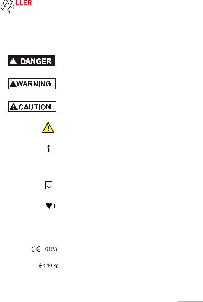
The safety level is classified according ANSI Z535.4. The following overview shows the safety symbols and pictograms used in this handbook.
For a direct danger which could lead to severe personal injury or to death.
For a possibly dangerous situation, which could lead to bodily injury or to death.
For a possibly dangerous situation which could lead to personal injury. This symbol is also used to indicate possible damage to property.
For general safety notes as listed in this chapter. When this symbol is displayed on the unit, it means that the user should refer to the user guide.
Note for possible dangerous situations which could lead to damage to property or system failure. Important or helpful user information.
Reference to other guidelines.
Potential equalization.
CF symbol. This unit is classified safe for direct cardiac application. Only defibrillation protected when used with the original SCHILLER patient cable.
The unit/component can be recycled.
Notified body of the CE certification (TÜV P.S.).
Is intended for infants weighing less then 10 kg.
Page 7

|
2 |
Introduction |
||
|
2.1 |
MT-101/200 Range of Application |
MT-101/MT-200 |
|
2 Introduction
The SCHILLER Holter system comprises two main parts. The MT-101 Holter recorder and the MT-200 program. Recordings made by the MT-101 unit are downloaded to the MT-200 for display, storage and analysis.
2.1MT-101/200 Range of Application
|
HILLER |
Software on |
this CD |
||||||||||||||||||||||||||||||||||||
|
rights |
for SC |
belo |
ng |
|||||||||||||||||||||||||||||||||||
|
rty |
to |
|||||||||||||||||||||||||||||||||||||
|
pe |
SC |
|||||||||||||||||||||||||||||||||||||
|
pro |
||||||||||||||||||||||||||||||||||||||
|
ial |
HIL |
|||||||||||||||||||||||||||||||||||||
|
rc |
LER |
A |
||||||||||||||||||||||||||||||||||||
|
e |
||||||||||||||||||||||||||||||||||||||
|
m |
G, |
|||||||||||||||||||||||||||||||||||||
|
om |
S |
|||||||||||||||||||||||||||||||||||||
|
c |
wi |
|||||||||||||||||||||||||||||||||||||
|
d |
t |
|||||||||||||||||||||||||||||||||||||
|
n |
SCHILLER |
er |
l |
|||||||||||||||||||||||||||||||||||
|
a |
a |
|||||||||||||||||||||||||||||||||||||
|
l |
l |
|||||||||||||||||||||||||||||||||||||
|
n |
||||||||||||||||||||||||||||||||||||||
|
ia |
d |
|||||||||||||||||||||||||||||||||||||
|
str |
A |
|||||||||||||||||||||||||||||||||||||
|
u |
. |
|||||||||||||||||||||||||||||||||||||
|
in |
d |
l |
||||||||||||||||||||||||||||||||||||
|
i |
||||||||||||||||||||||||||||||||||||||
|
h |
||||||||||||||||||||||||||||||||||||||
|
ll |
r |
t |
||||||||||||||||||||||||||||||||||||
|
A |
g |
|||||||||||||||||||||||||||||||||||||
|
s |
. |
S W I T Z E R L A N D |
s |
|||||||||||||||||||||||||||||||||||
|
e |
r |
|||||||||||||||||||||||||||||||||||||
|
m |
e |
|||||||||||||||||||||||||||||||||||||
|
v |
||||||||||||||||||||||||||||||||||||||
|
a |
s |
|||||||||||||||||||||||||||||||||||||
|
e |
||||||||||||||||||||||||||||||||||||||
|
N |
r |
|||||||||||||||||||||||||||||||||||||
|
d e |
SDS-200 2.01 |
d |
||||||||||||||||||||||||||||||||||||
|
. |
||||||||||||||||||||||||||||||||||||||
|
ra |
SDS-104 2.01 |
S |
||||||||||||||||||||||||||||||||||||
|
T |
C |
|||||||||||||||||||||||||||||||||||||
|
d |
SEMA-200 1.81 |
H |
||||||||||||||||||||||||||||||||||||
|
a |
L |
|||||||||||||||||||||||||||||||||||||
|
n |
L |
|||||||||||||||||||||||||||||||||||||
|
I |
||||||||||||||||||||||||||||||||||||||
|
ks |
SEMA-COMM 1.80 |
E |
||||||||||||||||||||||||||||||||||||
|
r |
R |
|||||||||||||||||||||||||||||||||||||
|
a |
MT-190/200 1.80 |
A |
||||||||||||||||||||||||||||||||||||
|
M |
, |
|||||||||||||||||||||||||||||||||||||
|
G |
||||||||||||||||||||||||||||||||||||||
|
e |
MS-3 2.03 |
H |
||||||||||||||||||||||||||||||||||||
|
a |
||||||||||||||||||||||||||||||||||||||
|
d |
C |
|||||||||||||||||||||||||||||||||||||
|
r |
BR-102 2.40 |
— |
||||||||||||||||||||||||||||||||||||
|
d |
3 |
|||||||||||||||||||||||||||||||||||||
|
T |
6 |
|||||||||||||||||||||||||||||||||||||
|
e |
4 |
|||||||||||||||||||||||||||||||||||||
|
s |
Demo Sema-200 |
Part No. 2.100256 B |
||||||||||||||||||||||||||||||||||||
|
t |
||||||||||||||||||||||||||||||||||||||
|
r |
1 |
|||||||||||||||||||||||||||||||||||||
|
e |
Demo MT-200 |
|||||||||||||||||||||||||||||||||||||
|
g |
a |
|||||||||||||||||||||||||||||||||||||
|
i |
Version x.xx |
a |
||||||||||||||||||||||||||||||||||||
|
r |
, |
|||||||||||||||||||||||||||||||||||||
|
e |
System Software |
r |
||||||||||||||||||||||||||||||||||||
|
e |
S |
|||||||||||||||||||||||||||||||||||||
|
r |
Release Notes |
w |
||||||||||||||||||||||||||||||||||||
|
E |
z |
|||||||||||||||||||||||||||||||||||||
|
a |
i |
|||||||||||||||||||||||||||||||||||||
|
t |
||||||||||||||||||||||||||||||||||||||
|
P |
e |
|||||||||||||||||||||||||||||||||||||
|
O |
Acrobat Reader 4.0 |
a |
||||||||||||||||||||||||||||||||||||
|
l |
||||||||||||||||||||||||||||||||||||||
|
S |
n |
|||||||||||||||||||||||||||||||||||||
|
C |
.d |
|||||||||||||||||||||||||||||||||||||
|
N |
||||||||||||||||||||||||||||||||||||||
|
I |
llA |
|||||||||||||||||||||||||||||||||||||
|
M |
||||||||||||||||||||||||||||||||||||||
|
I |
||||||||||||||||||||||||||||||||||||||
|
d |
o |
|||||||||||||||||||||||||||||||||||||
|
n |
t |
|||||||||||||||||||||||||||||||||||||
|
a |
re |
|||||||||||||||||||||||||||||||||||||
|
M |
For further information please visit our homepage |
|||||||||||||||||||||||||||||||||||||
|
A |
a |
|||||||||||||||||||||||||||||||||||||
|
E |
t |
|||||||||||||||||||||||||||||||||||||
|
S |
www.schiller.ch or send an e-mail to sales@schiller.ch |
m |
e |
|||||||||||||||||||||||||||||||||||
|
S |
||||||||||||||||||||||||||||||||||||||
|
, |
||||||||||||||||||||||||||||||||||||||
|
U |
st |
n |
||||||||||||||||||||||||||||||||||||
|
G |
||||||||||||||||||||||||||||||||||||||
|
R |
a |
|||||||||||||||||||||||||||||||||||||
|
, |
n |
|||||||||||||||||||||||||||||||||||||
|
T |
||||||||||||||||||||||||||||||||||||||
|
A |
||||||||||||||||||||||||||||||||||||||
|
V |
||||||||||||||||||||||||||||||||||||||
|
I |
rt |
|||||||||||||||||||||||||||||||||||||
|
O |
||||||||||||||||||||||||||||||||||||||
|
N |
d |
a |
||||||||||||||||||||||||||||||||||||
|
O |
||||||||||||||||||||||||||||||||||||||
|
S |
an |
e |
||||||||||||||||||||||||||||||||||||
|
T |
||||||||||||||||||||||||||||||||||||||
|
, |
m |
|||||||||||||||||||||||||||||||||||||
|
IV |
||||||||||||||||||||||||||||||||||||||
|
OR |
se |
|||||||||||||||||||||||||||||||||||||
|
CI |
eb |
|||||||||||||||||||||||||||||||||||||
|
M, |
nol |
|||||||||||||||||||||||||||||||||||||
|
TIV |
g |
|||||||||||||||||||||||||||||||||||||
|
ORI |
ot |
|||||||||||||||||||||||||||||||||||||
|
PS |
,TIV |
eht |
||||||||||||||||||||||||||||||||||||
|
OID |
RAC , |
ceps |
erri |
|||||||||||||||||||||||||||||||||||
|
RELLIHC S |
.sr ed loh |
The MICROVIT MT-101 Holter is designed to record long-term electrocardiograms for the diagnosis of symptomatic and asymptomatic arrhythmias, i.e. bradycardia and tachycardia, and for patients after resuscitation or suffering from diseases such as cardiomyopathy, high blood pressure or long QT syndrome.
The recording can also be used to help examine palpitations or syncopes and dizziness, to verify medical therapies, and to carry out subsequent treatments after a bypass operation or a PTCA. The ST segment analysis of an ECG recording allows the detection of a symptomatic or asymptomatic ischemia.
Good signal quality is vital for the success of a recording. The built-in Holter display, enables the ECG signal quality to be checked before starting, and the recording commenced directly from the device. This gives a high degree of reliability.
At the end of a recording, the data is transferred from the Holter recorder to a PC. The transfer of a recording typically only requires a few minutes.
The MT-200 is a PC based ECG evaluation program. An ECG is recorded using the SCHILLER MICROVIT MT-101 Holter. Two or 3-channel ECG recordings can be recorded over a period up to 72 hours. After the transfer of the recording data into the MT-200 program, the data can be displayed, saved, analysed and printed. The MT200 program enables quick access to the recording data and displays the ECG and analysis data in a logical and understandable way for diagnosis.
Page 8
![]()
|
MT-101/MT-200 |
User Guide |
Introduction |
2 |
|
|
MT-101/200 Range of Application |
2.1 |
|||
The MT-200 includes analysis of the following:
|
Supraventricular Arrhythmias |
• |
supraventricular extrasystoles |
|
• |
couplets |
|
|
• |
triplets |
|
|
• chain of four or more SVES |
||
|
• |
(SV tach) |
|
|
• |
bigeminy |
|
|
• |
trigeminy |
|
|
Sinus Rhythm Alterations |
• |
tachycardia |
|
• |
bradycardia |
|
|
• |
pause |
|
|
• |
abs. arrhythmias |
|
|
Ventricular Arrhythmias |
• |
ventricular extrasystoles |
|
• |
couplets (VES chain) |
|
|
• |
triplets |
|
|
• chain of four or more VES |
||
|
• |
(V tach) |
|
|
• |
bigeminy |
|
|
• |
trigeminy |
|
|
• |
R on T |
|
|
Heart Rate Trend |
• |
calculated over 4, 8 or 16 beats and |
|
• averaged over 1 to 10 minutes |
||
|
ST Trend |
• |
setting of the distance from J-point for ST measurement (J-point + 10 to 100 ms) |
|
• episodes detected separately for channel 1, and/or channel 2, and/or channel 3 |
||
|
when ST level is exceeded (1 to 3 mm) |
||
|
Pacemaker |
• |
6 pacemaker templates |
|
• |
heart rate variability |
|
|
• tachograms and tabular presentation after analysis of the recording |
Art. no.: 2.510492 rev.: b
Page 9
|
2 |
Introduction |
||
|
2.2 |
MT-101 Components and Operation |
MT-101/MT-200 |
|
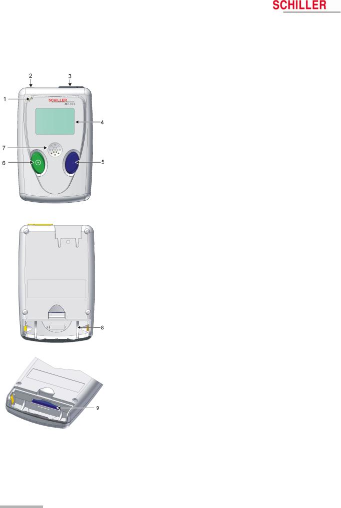
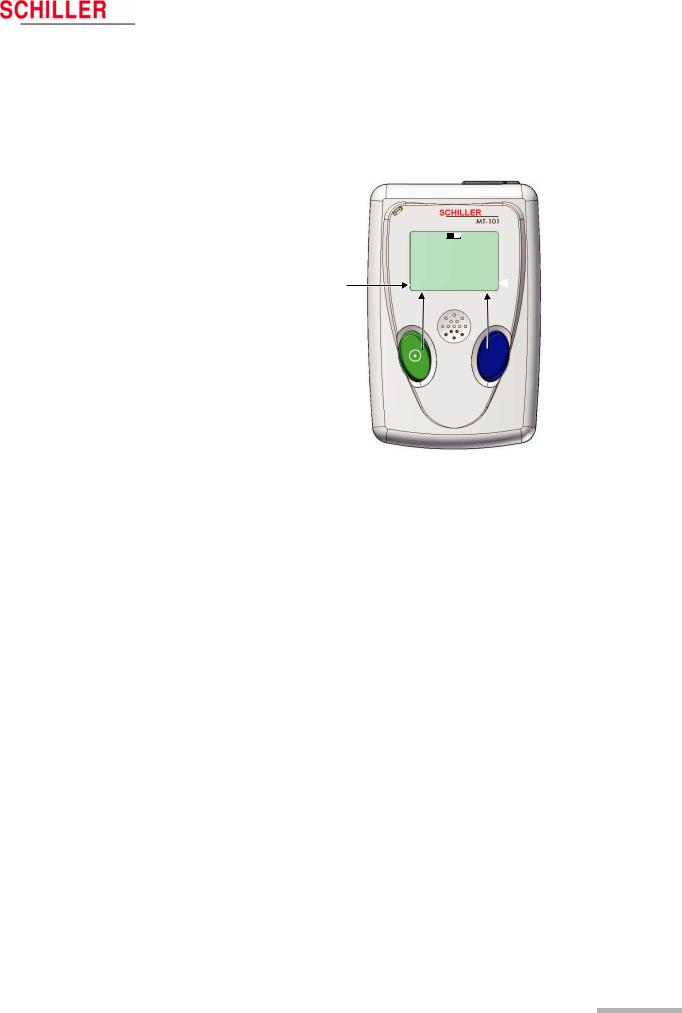
2.2MT-101 Components and Operation
Front
(1)Microphone for patient identification
(2)Patient cable connection
(3)USB-cable connection
(4)LCD display
(5)Programming button
(6)On/off and programming button
(7)Loudspeaker
Back
(8)Battery housing
(9)SD memory card
Programming
The MT-101 Holter can be programmed simply using the two keys following the menu guidance on the LCD display.
Data transmission
The ECG data transmission to the PC can be realised in two ways:
–directly via standard USB connection (3)
–by removing the memory card (9) from the battery housing and transmitting the data to the PC by means of a memory card reader. The advantage resulting from this procedure is that the Holter can be equipped with a new memory card and is immediately available for the next patient.
Page 10
|
MT-101/MT-200 |
User Guide |
Introduction |
2 |
|
Operating and Display Elements |
2.3 |
|||
2.3Operating and Display Elements
The Microvit MT-101 is operated with the two buttons and the menu guidance on the LCD. The green key with the switching-on symbol is used additionally to switch the device on and off.
Functions green button:
On/off
NEXT
EVENT SPEED 1x — 3x NO
Functions of the blue button:
OK CHANGE EVENT YES CHANN2/3
Art. no.: 2.510492 rev.: b
2.3.1Switching on
Press the green button. The display shows the name and version number of the device before the main menu is displayed.
2.3.2Switching off
Keep the green button pressed for five seconds. When the button is released, the device is switched off. If an ECG recording is running, first stop it following the same procedure.
If no recording is running, the device will be switched off automatically after five minutes.
2.3.3Battery display
The battery symbol indicates the battery’s load status. If the battery is full, the symbol is solid — also see para. 2.5.2 Inserting/changing the battery, page 13.
2.3.4Status display
The operating status is displayed in the left upper corner of the LCD. REC for recording, USB if the MT-101 is connected to a PC, USB* for data transmission to a PC.
Page 11

|
2 |
Introduction |
||
|
2.4 |
MT-101 Menu Structure |
MT-101/MT-200 |
|
2.4MT-101 Menu Structure
The menus are selected with the green button (NEXT). A selected menu is opened with the blue button. Depending on the called menu, the button functions may change.)
MAIN 
 15:45
15:45
RECORD START
RECORD SETUP
LAST RECORD
SYSTEM INFO
SYSTEM SETUP
2.4.1Menu Overview
|
Main Menu |
Sub-Menu 1 |
Value/Info |
Sub-Menu 2 |
Value/Info |
Sub-Menu 3 |
Value/Info |
|
|
RECORD START |
ECG Signal |
Chan1 |
speed |
x1, x2 or x3 |
|||
|
ECG Signal |
Chan2 |
speed |
x1, x2 or x3 |
||||
|
ECG Signal |
Chan3 |
speed |
x1, x2 or x3 |
||||
|
Start record? |
Yes/No |
||||||
|
ECG-recording start- |
Yes |
> |
Event button |
Event saved! |
|||
|
ed! |
|||||||
|
> |
Record info |
||||||
|
> |
Stop recording? |
ECG recording |
Main |
||||
|
stopped |
|||||||
|
RECORD SETUP |
Patient ID |
> |
Voice-record |
> |
Start |
Start Recording |
|
|
Stop |
Stop Recording |
||||||
|
> |
Play ID |
> |
Stop |
Stop Playing |
|||
|
PM Det.* |
On/off |
||||||
|
Duration |
24, 48, 72 |
||||||
|
Sampling 125 Hz |
|||||||
|
LAST RECORD |
Patient ID* |
||||||
|
Events* |
> |
Events |
|||||
|
SYSTEM INFO |
SerNo. |
||||||
|
Version |
|||||||
|
Bat Type |
|||||||
|
SD-Card |
|||||||
|
SYSTEM SETUP |
Contrast |
1…8 |
|||||
|
Language |
ENG … |
||||||
|
Bat |
Alkaline |
||||||
|
NiMH2100 |
|||||||
|
Date/time |
> |
Year |
2000….2099 |
||||
|
> |
Month |
01….12 |
|||||
|
> |
Day |
01….31 |
|||||
|
> |
Hour |
00.23 |
|||||
|
> |
Minute |
00….59 |
|||||
* To record pacemaker pulses it is important that ‘PM Det‘ is set to on — see para. 5.1.1 Pacemaker, page 21.
Page 12

Art. no.: 2.510492 rev.: b
|
MT-101/MT-200 |
User Guide |
Introduction |
2 |
|
Initial Operation |
2.5 |
|||
2.5Initial Operation
2.5.1Unpacking
Check that all ordered items are present and free of shipping damage. Immediately report any damage to SCHILLER AG.
2.5.2Inserting/changing the battery
Open the battery compartment and insert the supplied battery or accumulator. Observe the polarity!
Note
The delivered battery is of alkaline type AA/LR6. If you use an NiMH 2100 mAh accumulator, make sure that BAT NiHM is selected in the SYSTEM SETUP menu. If the wrong type is selected, the battery capacity will not be displayed correctly.
On closing the battery cover, pay attention that the two lugs (A) are inserted correctly. The cover is closed in the direction indicated by the arrow (B). In order to engage the cover, press it down (at position C) until it clicks in place.
|
V Attention — danger of explosion Do not dispose of batteries by fire or incinera- |
||||||
|
tor. |
||||||
|
V Attention — danger of acid burn Do not open the battery casing. |
||||||
|
Only dispose of batteries in official recycling centres or municipally approved areas. |
||||||
|
Switch on the device and check the battery charge capacity. The battery symbol must |
||||||
|
Full |
be fully black. This corresponds to a maximum recording time of 24 hours. |
|||||
|
Half full |
An audible and visual indication is given during recording when battery capacity is |
|||||
|
Empty |
||||||
|
limited. The time will vary according to the type of battery installed (alkaline or |
||||||
|
NiMH2100) — but is normally between 1 and 2 hours. When the alarm is given and |
||||||
|
recording is to be continued, we recommend that the battery is replaced at the first |
||||||
|
opportunity — see para. 2.5.2 Inserting/changing the battery, page 13 |
||||||
|
When recording is stopped because of low battery capacity, and the battery is |
||||||
|
replaced within 5 hours of the unit switching off, the recording will continue — see para. |
||||||
|
3.2.1 During the Recording and Patient Information, page 17. |
Page 13

|
3 |
Preparing a Holter Recording |
||
|
3.1 |
Position of the Electrodes |
MT-101/MT-200 |
|
3Preparing a Holter Recording
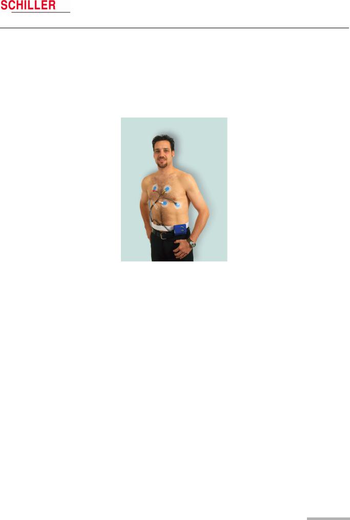
3.1Position of the Electrodes
Typical electrode position for a 4-lead cable (2-channel recording)
The recommended electrode placement for a 2-channel recording is shown below.
Channel 1 positive (K1+) = green
Channel 1 negative (K1-) = red
Channel 2 positive (K2+) = white
Channel 2 negative (K2-) = yellow
|
K1- |
1 |
K2 — |
|
|
K2 + |
2 |
||
|
3 |
K3 + |
||
|
K3 — |
4 |
||
|
5 |
|||
|
K1 + |
Typical electrode placement for a 6-lead cable (3-channel recording)
The recommended electrode placement for a 3-channel recording is shown below.
Channel 1 positive (K1+) = green Channel 1 negative (K1-) = red Channel 2 positive (K2+) = white Channel 2 negative (K2-) = yellow
Channel 3 positive (K3+) = orange (positioned on the patient’s back) Channel 3 negative (K3-) = blue
Page 14
MT-101/MT-200
Channel 1
Channel 2
Channel 3
Art. no.: 2.510492 rev.: b
|
User Guide |
Preparing a Holter Recording |
3 |
|
Position of the Electrodes |
3.1 |
Electrode Placement
Form a stress loop in every cable and secure them with adhesive strips to relieve the electrodes (strain relief). In order to ensure good data evaluation, the ECG amplitudes should be examined in the sitting, lying and standing position of the patient.
Holter ECGs use a bipolar lead system (one positive and one negative lead) for each channel. Channel 1 approximates to modified lead V5, channel 2 approximates to modified lead V2 and channel 3 approximates to modified lead V3.
Place the RED negative electrode under the clavicle on the right Sternal margin. Place the GREEN positive electrode in the fifth left intercostal space on the anterior axillary line (position approximately equates to V5).
Place the YELLOW negative electrode under the clavicle on the left sternal margin. Place the WHITE positive electrode in the fourth left intercostal space on the anterior axillary line (position approximately equates to V2).
Place the BLUE negative electrode in the fourth left intercostal space near the sternum.
Place the ORANGE positive electrode on the back in the fifth left intercostal space, between the spine and the scapula (position approximately equates to V3).
•The above electrode placement is suggested; other electrode configurations are possible.
•Ensure that the QRS complex is bigger than the T wave.
•Ensure that the trace is larger than 1mV. See 1mV reference (4) on following page.
•To avoid artifacts in women patients, the red and white electrodes can be placed lower if necessary.
Page 15

|
3 |
Preparing a Holter Recording |
||
|
3.2 |
Commencing a Holter Recording |
MT-101/MT-200 |
|
3.2Commencing a Holter Recording
The ECG recording can be started without the MT-200 PC software. The most important data can be entered in the MT-101 directly, and the ECG signal examined directly on the LCD.
A recording can also be started from the MT-200 program where all channels can be viewed simultaneously before commencing — see para. 5.1 Starting a Recording from the MT-200 Program, page 19.
Preparing the patient
1.Attach electrodes to patient.
Setting up the Holter MT-101
2.Press button (1) to switch on MT-101. Check battery charge capacity. If the symbol is only half filled out, change battery.
3.Choose NEXT (1) to select RECORD SETUP menu to make recording settings:
–Patient ID — record patient ID using the microphone and playback facility
–Select Pacemaker detection on or off — see para. 5.1.1 Pacemaker, page 21
–Define period of recording — 24, 48 or 72 hours
Checking the ECG signal
4.Connect patient cable to MT-101 (3).
5.Confirm RECORD START menu with “OK” (2) and check ECG signal Channel 1. Press CHAN2/3 to select and check channel 2/3. Press “OK” (2) to access START RECORDING panel.
The signal’s max. amplitude corresponds to the height of the moving line (5). The 1mV amplitude reference is the vertical line on the left (4). Ensure the signal amplitude is greater than 1mV.
Starting an ECG recording
6.Confirm the start of the recording with YES (2).
Stopping the ECG recording
7.Press and hold button (1) for 5 seconds. You will be prompted if you wish to stop the recording. Confirm with YES (2).
NOTE: If no confirmation is received to cease recording (button (2) pressed), within 15 seconds, the unit returns to recording mode.
Switching off the MT-101
8.If the unit is recording, first stop the recording step (7).
9.Ensure the main menu is displayed and that the cursor is at the RECORD START position.
10.Press and hold button (1) for 5 seconds to switch the device off.
Page 16

Art. no.: 2.510492 rev.: b
|
MT-101/MT-200 |
Preparing a Holter Recording |
3 |
|
User Guide Taking an Extended Recording (Longer than 24 hours) |
3.3 |
||
REC 

 8:56
8:56
ECG recording (00:02)
1 2
3.2.1During the Recording and Patient Information
Inform the patient about the use of the MT-101.
Event record
•Every event should be entered in the diary, together with the time, the activities at the time of occurrence and the symptoms.
•Instruct the patient to press the EVENT button at any time during the recording to register an event as follows:
1.Press button (1 or 2).
2.Record event in the patient diary. Note:
The template for the patient diary is stored on the software CD as Word or pdf file. An example is given at the end of the book — see para. 13 Patient Diary, page 89.
No ECG signal or lead-off
1.Check cable connection on device.
2.Check cable connection on electrodes.
3.Re-attach electrodes to body.
General information
The device is not waterproof. The patient should be advised not to take a bath or shower during the recording.
Battery replacement during the recording.
Change battery when an audible indication is given and the message ‘BATTERY LOW — change battery’ is displayed the MT-101. — this will occur approximately 1-2 hours before switch off (dependent on battery type). Proceed as follows:
1.Press EVENT button (1 or 2) and make an entry in your diary.
–DO NOT SWITCH THE DEVICE OFF
2.Open battery compartment and replace battery with a new one of the same type. Observe correct polarity, and replace battery cover — see para. 2.5.2 Inserting/ changing the battery, page 13.
3.Switch the device on by pressing button (1). After a few seconds the message ‘ECG recording restart’ is displayed while the unit re-initialises. This is followed by the message ‘ECG recording’ and ECG recording automatically resumes.
When a recording is stopped (because of low battery capacity or because of battery removal), the battery must be replaced within 5 hours of the unit switching off for the recording to continue.
3.3Taking an Extended Recording (Longer than 24 hours)
The MT-101 can record up to 72 hours of Holter data if required. To make a recording longer than 24 hours, the battery in the MT-101 must be changed as detailed above. An audible alarm and visual indication will be given when the battery must be changed.
Page 17

|
4 |
Transferring a Recording to the PC |
||
|
4.1 |
Data Transmission to PC from MT-101 |
MT-101/MT-200 |
|
4Transferring a Recording to the PC
4.1Data Transmission to PC from MT-101
1.Connect the USB cable between the MT-101 and PC (see picture below — the rubber cover on the MT-101 must be removed — the message «MT-101 connected to PC» appears.
2.Start MT-200 software on PC.
3. Click on the data transfer icon and select «Request Holter Data». The dialogue box shows the transferred data in per cent.
The data is stored automatically. If no patient data is entered, the file will be saved with the date and time.
4.2Data transmission to PC with Memory Card Reader
1.Connect the card reader to the USB. The memory card reader appears as a physical drive on your desktop.
2.The path name for this drive must be entered in the menu Option/System/Path/ SD-Card path — see para. 8.5.3 Directories, page 76.
3.Insert the memory card in the card reader or PCMCIA adapter.
4.Execute the function “Read SD-Card”. The data is read into the indicated path (for path location see point 2)
Data can also be imported from an SD card — see para. 7.2.3 Importing recordings, page 65
Page 18
![]()
Art. no.: 2.510492 rev.: b
|
MT-101/MT-200 |
User Guide |
Displaying an ECG Signal |
5 |
|
Starting a Recording from the MT-200 Program |
5.1 |
|||
5Displaying an ECG Signal
5.1Starting a Recording from the MT-200 Program
1. Start the MT-200 program on your PC /CS-200. The welcome page is displayed.
1
2.Click on the “New recording” icon (1). The patient data screen is displayed:
1
3.Enter the patient data and confirm with the «OK» button. To enter the data, click with the mouse cursor into the fields or jump from entry field to entry field using the tab key.
4.If pacemaker detection is required check the pacemaker box (1) — see para. 5.1.1 Pacemaker, page 21 for notes on pacemaker detection
Page 19

|
5 |
Displaying an ECG Signal |
||
|
5.1 |
Starting a Recording from the MT-200 Program |
MT-101/MT-200 |
|
5.When the patient data has been entered and Ok is clicked, enter the duration of the recording
Note: The data displayed or entered on the other pages of patient information — selected by clicking on the tabs at the top of this window (Recording data, Assignment etc.) — are only available after a recording has been made.
6.Place the electrodes as indicated in the dialogue box.
If a 4-lead patient cable was used for the Holter recording, only two channels will be displayed in the MT-200.
7.Check the signal and re-apply the electrodes if necessary.
Page 20

Art. no.: 2.510492 rev.: b
|
MT-101/MT-200 |
User Guide |
Displaying an ECG Signal |
5 |
|
|
Starting a Recording from the MT-200 Program |
5.1 |
|||
8.Click on START RECORDING to commence the recording. The dialogue box reminds you to check the battery load capacity.
The recording has now commenced. The LCD of the MT-101 indicates that ECG recording has been started.
Remove the USB from the MT-101 Holter recorder and close the connector again with the protective cover.
5.1.1Pacemaker
The MT-200 cannot determine pacemaker spikes itself and it is not possible to detect pacemaker signals by later analysing the recording in the program if the pacemaker detection function was not enabled during the original recording. So that the MT-200 can detect pacemaker spikes, pacemaker detection must be activated before the start of the recording.
Activating Pacemaker Detection
Pacemaker detection can be activated in either the MT-200 program or the MT-101:
«If the recording is started from the MT-200 program, then pacemaker activation can be carried out in the MT-200 by ticking the pacemaker box in the patient data window — see para. 5 Displaying an ECG Signal, page 19.
«If the recording is started from the MT-101 itself, then pacemaker activation must be carried out in the MT-101 menu > RECORD SETUP > PM Detection > ON, —
see para. 2.4.1 Menu Overview, page 12.
«
Detection and Recording of Pacemaker Spikes
The MT-101 only detects pacemaker signals in long-term ECG recordings when the slopes and amplitudes of the signal exceed the preset limits and when pacemaker detection is enabled. As the MT-101 uses a sampling frequency of 500 Hz for a recording (i.e. a digitalisation interval of 2 ms), complete digital processing is impossible due to the short duration of some pacemaker signals (less than 1 ms). Therefore, analogue processing of the ECG signals is applied by the MT-101 for pacemaker detection.
Analogue Pacemaker Detection in Channel 1
Analogue pacemaker detection is confined to the first channel of the MT-101. It is therefore optimal when the amplitude of the pacemaker signal for the first ECG channel is greater than that for the second channel. In some instances, this is not the case. In this case, it is recommended that the real-time ECG traces are viewed on the screen before starting the long-term recording. Pacemaker detection is automatically enabled on the real-time display. The pacemaker signals, however, are not always detected. If this is the case and the amplitude of the pulse is greater in the second channel, simply exchange the electrodes of channels 1 and 2. After the real-time display, pacemaker detection must be enabled for long-term recording in the MT-200!
Evaluation and Display of Pacemaker Spikes in the MT-200 Program
Pacemaker signals are marked in the MT-200 program by vertical lines in the ECG after evaluation of the recording. Note that these lines are correctly positioned in relation to time but are not proportional in either amplitude (voltage) or duration of the pacemaker pulse, nor do they indicate the polarity. The pacemaker representation is always positive but the actual pacemaker spike may be positive or negative.
Page 21
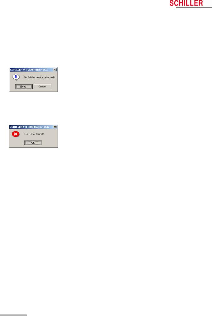
|
5 |
Displaying an ECG Signal |
||
|
5.2 |
Transmission Problems |
MT-101/MT-200 |
|
5.2Transmission Problems
If an error message appears either before starting a recording or when attempting to transfer a recording from the MT-101 to the PC, possible causes are as follows:
|
Error |
Cause |
Remedy |
|
|
• The USB cable assembly is not inserted |
« Check that both the cable connectors |
||
|
correctly in either the MT-101 or the PC. |
are securely placed. |
||
|
• The SCHILLER USB driver has not been |
« Install USB driver (on SCHILLER soft- |
||
|
installed |
ware CD. |
||
|
Communication Error (error |
• The device is not connected. |
« Connect the device. |
|
|
message displayed) |
• The SD memory card is not inserted. |
« Check the memory card. |
|
|
• Unit not switched on |
« Switch unit on |
||
|
• Battery exhausted. |
« Change batteries |
||
|
• Another device is connected to the USB. |
« Disconnect the device and connect the |
||
|
MT-101. |
|||
|
Display of DEMO VERSION |
• The hard-lock key is not present or incor- |
« |
Check the hard-lock key on the PC. |
|
rectly inserted. |
« |
Contact SCHILLER for network license |
|
|
• There is no license. |
|||
|
No error message. The program |
• With an USB installation, the program can |
1. |
Close the MT-200 program. |
|
cannot find the Holter. |
occasionally «hang» and not recognise |
2. |
Disconnect the USB connector to your |
|
the USB connection. |
PC. Wait circa three seconds and re- |
||
|
place the connector. |
|||
|
3. |
Open the MT-200 program again. |
||
Page 22

Art. no.: 2.510492 rev.: b
|
MT-101/MT-200 |
User Guide |
Displaying an ECG Signal |
5 |
|
|
Transmission Problems |
5.2 |
|||
5.2.1Checking the connection
A test function is available to check the integrity of the connection between the MT101 and the PC. To carry out the test function, proceed as follows:
1.In the «Options» menu, select «System».
2.Click the «Holter» tab.
3.Check the correct box for your installation (USB or AT card), and click the «Test Connection» icon. Follow the instructions on the screen.
4.When «OK» is clicked, the software sends a test message to/from the MT-101.
5.A message box indicates the success of the transmission.
If the problem could not be solved, check all connections, ensure the MT-101 is switched on, close the MT-200 application and restart the software.
Page 23
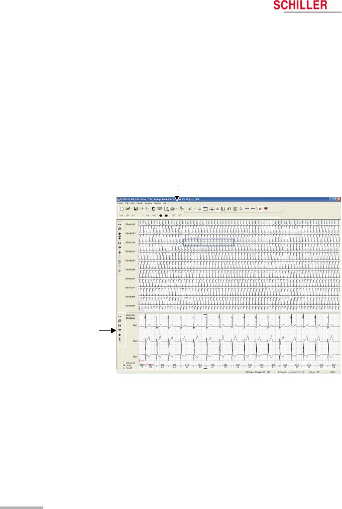
|
6 |
Viewing and Editing a Recording |
||
|
6.1 |
Icons |
MT-101/MT-200 |
|
6Viewing and Editing a Recording
6.1Icons
The MT-200 program gives different views for the presentation of a Holter recording. Every view offers various data and analytical information. Besides display icons, the toolbar contains additional function icons enabling the quick and easy activation of the most frequently used functions. All icons can be activated any time and in any view. In the ECG and zoom views, additional function icons are given to the left of the screen to change the size of the traces and/or the time segment of the recording.
Function and View icons
Function and View icons in the ECG overview
All icons are selected by mouse-click (position the cursor on the icon and click with the left mouse button).
When an icon is dimmed, it means that this function is not available for the currently displayed screen and cannot be selected. For example, the zoom function is not available in the ST view so the «Zoom» icon is dimmed. The patient name is always displayed at the top of the page when an ECG recording is displayed.
Page 24
Art. no.: 2.510492 rev.: b
|
MT-101/MT-200 |
User Guide |
Viewing and Editing a Recording |
6 |
|
|
Icons |
6.1 |
|||
6.1.1View icons
The function and view icons are only active (selectable) when a patient recording is displayed. When an icon function cannot be selected, the icon is dimmed.
|
Event View* |
This gives an overview of all events in the 24 hour |
|
period. Use this view to quickly identify and select |
|
|
a specific time segment for display. |
|
|
Analysis Summary View |
This provides a tabular overview of all important |
|
measurements for the entire 24 hour period. |
|
|
Event Samples View |
This allows three event samples from every event |
|
category to be displayed, i.e. selected or replaced. |
|
|
The user event samples can also be selected for |
|
|
ECG View* |
printing in this view. |
|
This zooms in on a specific time segment of ECG |
|
|
for closer analysis. The next page can also be |
|
|
displayed using the automatic scrolling function. |
|
|
Analysis Summary |
This provides a Tabular overview of the recording. |
|
ST Trend View |
(Option) This provides a graphical overview of the |
|
ST trend with tabular measurements for ST |
|
|
episodes. |
|
|
Template View |
(Option) This provides a graphical overview of the |
|
different types of averaged QRS waveforms with |
|
|
classification, detected over the entire recording. |
|
|
Pacemaker View |
(Option) This provides a graphical overview of |
|
QRS templates measured in relation to the |
|
|
pacemaker pulse. |
|
|
Heart Rate Variability |
(Option) This provides a graphical overview of the |
|
heart rate variability. |
|
|
Heart Rate Trend |
This provides a graphical overview of the heart |
|
rate trend. The maximum/minimum HR and NN |
|
|
interval can be manually defined |
|
|
Zoom View |
This gives a zoom view of a selected ECG |
|
segment. Specific QRS complexes can also be |
|
|
reclassified in this view. See «Reclassifying/Editing |
|
|
a QRS complex» later in this section. The two leads |
|
|
displayed in the zoom view are the two leads that |
|
|
have been analysed. The display will always |
|
|
contain two channels, even if only one channel has |
|
|
been analysed. |
|
|
HR Trend |
This displays the heart rate trend over the entire |
|
recording. |
If only one lead has been analysed, channel 1 is the second lead in the display. If channel 1 has been analysed, channel 2 is the second lead displayed.
Options
All options are enabled with a programmed hard-lock key. This hard-lock key can be obtained from SCHILLER AG.
*In event and ECG view modes, the lower part of the display is divided to give either ECG zoom or heart rate trend.
Page 25
|
6 |
Viewing and Editing a Recording |
||
|
6.1 |
Icons |
MT-101/MT-200 |
|
6.1.2Function icons
The following function icons are available when a patient recording is viewed:
|
Open Recording |
Open a recording. Click the icon to list all available |
|||
|
files.Click the arrow to the right of the icon, to list |
||||
|
the last four opened recordings. |
||||
|
New Recording |
Enter the data of a new patient and start a new |
|||
|
recording. |
||||
|
Save Recording |
Save the current recording. Click the arrow to the |
|||
|
right of the icon, to display further options to save |
||||
|
as a pdf file. If saved as PDF file, it is possible to |
||||
|
delete the original if desired. |
||||
|
|
Send the currently displayed recording by e-mail. |
|||
|
Click the arrow to the right of the icon, to give |
||||
|
further options to send as a pdf file. If “Send EMail |
||||
|
as PDF File” is selected, a pdf is generated and |
||||
|
automatically attached to the e-mail. |
||||
|
Patient and Recording View / edit patient and recording data. View |
||||
|
Data |
analysis settings and diagnosis. General recording |
|||
|
settings and options. |
||||
|
Print Preview |
Select and display the pages to be printed (before |
|||
|
printing) |
||||
|
|
Print (user defined) recording data. Click the arrow |
|||
|
to the right of the icon to select specific data for |
||||
|
print. |
||||
|
Request Holter Data |
Load data from the connected MT-101 Holter |
|||
|
recorder or via a memory card reader by selecting |
||||
|
«Read SD Card». In Win 95/98, a third function is |
||||
|
available to load data from a tape. |
||||
|
Analyse |
Click the Analyse icon to analyse the currently |
|||
|
displayed recording to the defined analysis |
||||
|
parameters. Click the arrow to the right of the icon |
||||
|
to analyse multiple recordings. |
||||
|
Scroll Back |
Scroll backwards (in time) of the zoom ECG |
|||
|
currently displayed. |
||||
|
Scroll Forward |
Scroll forwards (in time) of the zoom ECG currently |
|||
|
displayed. |
||||
|
Scroll Event Back |
Go to previous event. |
|||
|
Scroll Event Forward |
Go to next event. |
|||
|
Time Scale for View |
Display 3, 6, 12, 24 hours of analysed data or, for |
|||
|
recordings longer than 24 hours, all the data. |
||||
|
When 3, 6, 12, or 24 hour is selected, the arrow |
||||
|
icons at the side of the box, enable the user to |
||||
|
jump to the next time segment. |
||||
Page 26
Art. no.: 2.510492 rev.: b
|
MT-101/MT-200 |
User Guide |
Viewing and Editing a Recording |
6 |
|
|
Icons |
6.1 |
|||
6.1.3Tool icons in rhythm and zoom views
The tool icons are displayed in the rhythm and zoom views on the left hand side. Use these icons to:
•decrease or increase the amplitude and speed
•move up or down a line and page
•immediately print a selected half hour segment of the recording
•change the channel (ECG view)
•select and analyse specific channels (ECG view)
•select a zoom section of the recording for printing
The page up/down and line up/down icons are not applicable and not displayed in the zoom view
|
Centre |
In the ECG view, centres the selected (highlighted) |
||
|
ECG section in the middle of the screen. |
|||
|
In the zoom view, positions the selected QRS |
|||
|
complex (cursor above and below QRS complex) |
|||
|
|
slightly to the left of centre in the zoom screen. |
||
|
In the ECG view , immediately prints a 30 min. |
|||
|
segment of the recording (1/4 hour before and 1/4 |
|||
|
after the selected section). |
|||
|
In the zoom view, marks the displayed zoom |
|||
|
section as «selected». |
|||
|
Page Up |
Moves to the previous page. Each page displays |
||
|
between approximately 1 and 24 minutes of |
|||
|
Page Down |
recording dependent on the speed selected. |
||
|
Moves to the next page |
|||
|
Line Up |
Shifts the display up one line) |
||
|
Line Down |
Shifts the display down one line |
||
|
Decrease Speed |
Decreases the ECG scale (curves closer). |
||
|
Increase Speed |
Increases the ECG scale (curves wider). |
||
|
Increase Amplitude |
Curves bigger |
||
|
Decrease Amplitude |
Curves smaller |
||
|
Select Channel |
Select any combination of one, two or three |
||
|
channels (for display) |
|||
|
Select Channel for |
Select and analyse one or two channel |
||
|
Analysis |
|||
|
Auto Scroll Down |
Automatically scrolls down through the recording. |
||
|
Subsequent time segments are displayed |
|||
|
automatically |
Page 27
 Loading…
Article no: 2.511076 Rev.: g
Issue date: 13.12.21
Corresponds to: Original
Sales and Service Information
The SCHILLER sales and service centre network is world-wide. For the
address of your local distributor, contact your nearest SCHILLER
subsidiary. In case of difficulty a complete list of all distributors and
subsidiaries is provided on our internet site:
www.schiller.ch
Sales information can also be obtained from:
sales@schiller.ch
Address Headquarters
SCHILLER AG
Altgasse 68
CH-6341 Baar
Switzerland
BR-102 plus / BR-102 plus PWA bears the CE-0123 mark (Notified Body TÜV-SÜD Produkte Ser-
vice GmbH, Ridlerstr. 65, 80339 Munich, Germany), indicating its compliance with the essential re-
quirements of the Annex I of the Medical Device Directive 93/42/EE regarding safety, functionality
and labelling. The requirements apply to patients, users and third persons who come into contact
with this device within the scope of its intended use.
Tel: +41 (0) 41 766 42 42
Fax: +41 (0) 41 761 08 80
sales@schiller.ch
www.schiller.ch
- About
- Blog
- Projects
- Help
-
Donate
Donate icon
An illustration of a heart shape - Contact
- Jobs
- Volunteer
- People
Bookreader Item Preview
texts
Schiller CS 200 Service Manual
Schiller CS 200 Service Manual
- Addeddate
- 2020-05-20 09:17:44
- Classification
- Clinical;Cardiac Equipment;Electrocardiograph (ECG EKG);Welch Allyn Schiller ECG EKG;Schiller CS-200
- Identifier
- manual_Schiller_CS-200_Service_Manual
- Identifier-ark
- ark:/13960/t1ck75x62
- Ocr
- ABBYY FineReader 11.0 (Extended OCR)
- Page_number_confidence
- 48.70
- Ppi
- 600
- Scanner
- Internet Archive Python library 1.9.0
comment
Reviews
There are no reviews yet. Be the first one to
write a review.
SIMILAR ITEMS (based on metadata)

Schiller BR-102 plus сфигмоманометр 24 / 48 — часовой регистратор АД
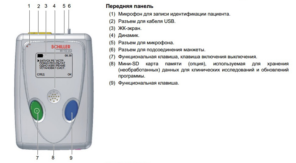
Schiller BR-102 plus — это прибор с управлением через меню и возможностью программирования пользователем. Прибор обеспечивает измерения АД в течение длительного периода времени. Измерение происходит через заранее определенные интервалы. Прибор может зарегистрировать до200 (400) измерений в течение 24 (48) часов. При исследовании все измерения будут сохранены в памяти прибора.
Отдельные измерения могут проводиться также в любой момент времени. BR-102 plus может использоваться автономно или с программой MT-300. Доступны две версии BR-102 plus, различающиеся по методу измерения:
• В версии 1 используется аускультативный метод измерения(по Рива-Роччи, Короткову). В качестве основного и осцилломерический в качестве дублирующего. Это означает, что если четкое измерение не может быть получено аускультативным методом, то используется осциллометрический метод.
Если ни один из методов не дает достоверного результата, измерение АД будет произведено повторно. Осциллометрический метод не может быть выбран в качестве основного метода измерения.
• В версии 2 используется только осциллометрический метод. Учтите, что приборы этой версии поставляются без микрофона в манжете.
Программа MT-300
MT-300 это программа на базе ПК, используемая для визуализации, хранения, редактирования, анализа и печати регистраций, произведенных на BR-102 plus. Эта программа также может использоваться для определения интервалов между измерениями и других установок для BR-102 plus и запуска длительной регистрации АД на BR-102 plus. Доступны две версии программы.
Версия MT-300 light
Базовая версия программы MT-300 обеспечивает все основные функции редактирования и просмотра перечисленные выше. Программа входит в стандартную комплектацию регистратора BR-102 plus.
Полная версия MT-300
Полная версия программы MT-300 включает в себя дополнительные возможности редактирования и коммуникации, например, генерация отчетов в формате pdf и их экспорт, последовательное сравнение, функции ГИС (GDT — германский стандарт передачи данных) и SEMA-200. Эта программа может бесплатно использоваться в тестовом режиме в течение 30 дней, после чего для активации полной версии потребуется серийный номер (поставляется компанией SCHILLER AG).
Комплектация Schiller BR-102 plus
Стандартная комплектация
- Регистратор BR-102 plus
- Два комплекта аккумуляторв NiMH 2300 мАч (всего 4 аккумулятора)
- Зарядное устройство для аккумулятора
- Манжета размера ‘M’ (средняя) для взрослых, и трубка давления с микрофоном (в версии с осциллометрическим методом измерения микрофона нет)
- Фиксирующий пластырь для манжеты (одноразовый, 10 шт)
- Фиксирующий пластырь для микрофона (одноразовый, 10 шт)
- Сумка для ношения регистратора с поясом
- SCHILLER CD с программой MT-300
- Кабель USB
- Руководство пользователя и краткое руководство пользователя
Дополнительные принадлежности
- Манжета размера ‘S’ (малая) для худощавых взрослых, детей
- Манжета размера ‘L’ (большая) для взрослых
- Мини-SD карта (16MБ)
- Программа MT-300 (полная версия)
Скачать инструкцию на Schiller BR-102 plus
Скачать инструкцию и другую документацию на Schiller BR-102 plus можно здесь.
Руководство пользователя ( user manual ) Schiller BR-102 plus на русском языке скачать.
Регистрационное удостоверение Schiller BR-102 plus скачать.
Так же смотрите УЗИ аппарат LOGIQ S8 GE.