- Manuals
- Brands
- Man Manuals
- Engine
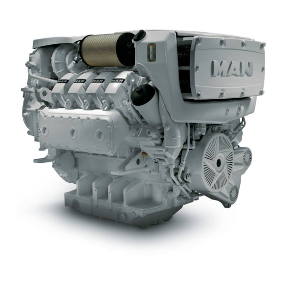
- D2868 LE433
- Operating instructions manual
-
Contents
-
Table of Contents
-
Troubleshooting
-
Bookmarks
Quick Links
Operating Instructions
MAN Marine Diesel Engines
D2868 LE433
D2862 LE433/453
D2862 LE423/443/463
51.99493-8578
«Translation of the original operating instructions»
Related Manuals for Man D2868 LE433
Summary of Contents for Man D2868 LE433
-
Page 1: Operating Instructions
Operating Instructions MAN Marine Diesel Engines D2868 LE433 D2862 LE433/453 D2862 LE423/443/463 51.99493-8578 “Translation of the original operating instructions”…
-
Page 2: Information And Copyright
Subject to technical alterations in the interests of further development. Reprinting, copying or translating of these instructions, even in part, is forbidden without written permission from MAN. All legal copyrights remain the exclusive property of MAN. © 2011 MAN Truck & Bus AG Vogelweiherstraße 33…
-
Page 3: Table Of Contents
…………. . Engine views V8-1200 (D2868 LE433) .
-
Page 4: Preface
You can find the approved products in the internet under: https://mmrepro.mn.man.de/bstwebapp/BSTServlet It is imperative and in your own interest to entrust your MAN Local Service Centre with the removal of any disturbances and with the performance of checking, setting, and repair work.
-
Page 5: Instructions
Instructions Important instructions which concern technical safety and protection of persons are emphasised as shown below. Danger: This refers to working and operating procedures which must be complied with in order to rule out the risk to persons. Caution: This refers to working and operating procedures which must be complied with in order to prevent damage to or destruction of material.
-
Page 6: Declaration
Declaration…
-
Page 7: Nameplates
The engine type plates are on the crankcase (see illustration). MAN Nutzfahrzeuge Aktiengesellschaft Model Type …………..Engine No. / Engine No.
-
Page 8: Safety Regulations
D Do not touch the engine with bare hands when it is warm from operation — risk of burns. Ë Ë Ë Ë D Exhaust gases are toxic. Comply with the instructions for the installation of MAN Diesel engines which are to be operated in enclosed spaces. Ensure that there is adequate ventilation and air extraction.
-
Page 9
Safety regulations D Electrical accessories and equipment from other manufactures may only be connected without the approval of MAN to the connections provided for the cu stomer or shipyard. The control of the engine may be adversely affected and thus may lead to property damage or personal injury and is therefore not permitted. -
Page 10
If faults occur, find the cause immediately and have it eliminated in order to prevent more serious damage. Use only genuine MAN spare parts. MAN will accept no responsibility for damage resulting from the install ation of other parts which are supposedly “just as good». -
Page 11
Safety regulations 3. Regulations designed to prevent pollution Engine oil and filter elements / cartridges, fuel / fuel filter D Take old oil only to an old oil collection point. D Take strict precautions to ensure that no oil or Diesel fuel gets into the drains or the ground. Caution: The drinking water supply could be contaminated. -
Page 12
Wait at least a minute until the pressure in the rail has dropped before loosening a screw connection If necessary check the pressure drop in the rail with MAN‐Cats D Risk of injury! People with pacemaker must keep at least 20 cm away from the running engine. -
Page 13
Safety regulations D Avoid air movements (any swirling of dust when starting engines) D The area of the still closed fuel system must be cleaned and dried with the aid of com pressed air D Remove detached particles of dirt such as paint chippings and insulation material with a suitable extractor (industrial type vacuum cleaner) D Cover areas of the engine compartment from which dust particles could be detached with clean foil… -
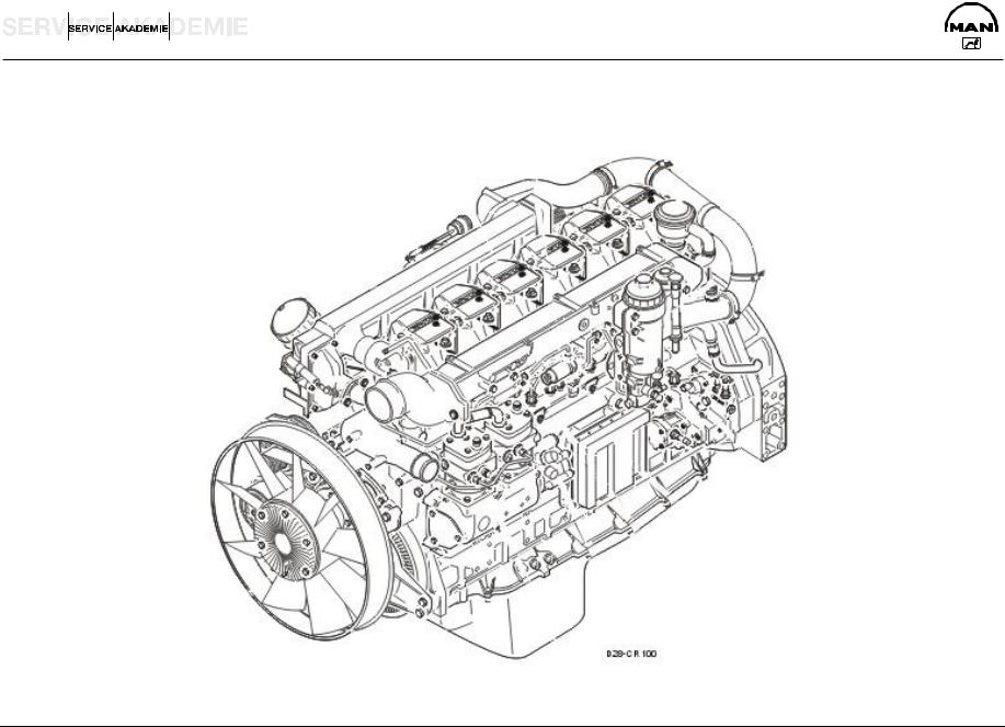
Page 14: Commissioning And Operation
Commissioning and operation Engine views V8-1200 (D2868 LE433)
-
Page 15
Commissioning and operation (1) Poly-V-belt guard (2) Air filter (3) Coolant filler neck (4) Main fuse for voltage supply (5) Oil drain valve engine (6) Oil drain valve gearbox (7) Oil filler neck (8) Oil filter (9) Oil dipstick (10) Fuel filter (11) Sea water pump (12) Engine terminal box EDC… -
Page 16: Engine Views V12-1800 (D2862 Le433) / V12-1650 (D2862 Le453)
Commissioning and operation Engine views V12-1800 (D2862 LE433) / V12-1650 (D2862 LE453)
-
Page 17
Commissioning and operation (1) Poly-V-belt guard (2) Air filter (3) Coolant filler neck (4) Main fuse (5) Oil drain valve gearbox (6) Oil drain valve engine (7) Oil filler neck (8) Oil filter (9) Oil dipstick (10) Fuel filter (11) Sea water pump (12) IEngine terminal box EDC… -
Page 18: Engine Views V12-1550 (D2862 Le423) / V12-1400 (D2862 Le443) / D2862 Le463)
Commissioning and operation Engine views V12-1550 (D2862 LE423) / V12-1400 (D2862 LE443) / D2862 LE463)
-
Page 19
Commissioning and operation (1) Poly-V-belt guard (2) Air filter (3) Coolant filler neck (4) Oil drain valve gearbox (5) Main fuse (6) Oil drain valve engine (7) Oil filler neck (8) Oil filter (9) Oil dipstick (10) Fuel filter (11) Sea water pump (12) IEngine terminal box EDC… -
Page 20: First Commissioning
Fill the cooling system of the engine with a mixture of drinkable tap water and anti-freeze agent on the ethylene glycole basis or anti-corrosion agent. See Publication “Fuels, Lubricants and Coolants for MAN Diesel Engines». D Pour in coolant slowly via expansion tank, see page 110…
-
Page 21: Seawater Pump
Commissioning and operation Seawater pump Do not let seawater pump run dry! Make sure that all valves / cocks in the seawater circuit are open. If there is a risk of frost, drain the seawater pump. Refilling with oil The engines are as a rule supplied without oil. Pour oil into engine via filler neck, see page 103.
-
Page 22: Commissioning
Commissioning and operation Commissioning Before daily starting the engine, check fuel level, coolant level and engine oil level and replenish, if neces sary. Caution: Use only approved fuels, lubricants etc. (see brochure Fuels, lubricants etc.»). Otherwise the liab ility for defects will become null and void! Checking oil level Check engine oil level only approx.
-
Page 23: Starting
Commissioning and operation Starting Danger: Before starting make sure that no-one is in the engine’s danger area. Caution: When starting do not use any additional starting aids (e.g. injection with starting pilot). There are two possibilities to start the engine: using the ignition lock or using the Start» button. Starting via the ignition lock: Ensure that the gearbox is in neutral.
-
Page 24: Operation Monitoring System
Do not put this engine into operation again until the fault has been eliminated. The engine is equipped as series standard with a monitoring and diagnostic system MAN-Marine-Dia gnose-System (MMDS. On the control console and alternatively on other control consoles, the following display devices are avail…
-
Page 25
Commissioning and operation Differences in operating parameters of engines and gearboxes Differences in parameters can be observed on identical engines, irrespective if they are installed in one boat or in different boats (boat series), such as D pressures D temperatures D speeds D fuel consumption D injection quantity… -
Page 26: Engine Room Panel
Commissioning and operation 1. Engine room panel (integrated LC display “IGN ON/OFF»-button, Start»-button, “Set+ Set-«-button and emergency stop switch) The engine room panel is optionally available and serves to display engine and gearbox data, as well as system information. In order to obtain the full functionality of an engine room panel, as well as the display additional function buttons are integrated for the control of the ignition.
-
Page 27
Commissioning and operation Function “Start» (4) (green button) With the ignition switched on, the engine can be started by pressing the green button “Start» (4). The button lights up green when the ignition is switched on. Function “Stop» (5) (yellow button) Actuation of the yellow button “IGN ON/OFF»… -
Page 28: Alarms And Flashing Lights
Commissioning and operation Optional External LC display of the ship-vehicle management computer (SFFR) in the cover of the engine terminal box Alarms and their codings can be indicated via the external LC display of the ship-vehicle management com puter and communicated to our customer service organisation. If an active MMDS alarm occurs the corresponding MMDS alarm page will be indicated automatically and can be exited only after confirmation.
-
Page 29
Commissioning and operation CAN bus-controlled display devices: 2. CAN-Bus round instruments, rev counter with information display and buttons D Rev counter (0-3000 rpm) with integrated LCD display for the following parameters and buttons for pa ging: Engine oil pressure Gearbox oil pressure Coolant temperature Engine oil temperature Engine exhaust temperature… -
Page 30
Commissioning and operation Tachometer CAN-Master The VDO Ocean Link Tachometer (CAN-Bus Tachometer) The VDO Ocean Link tachometer is a multifunctional instrument for indicating engine data, and is intended for use in navigation of sports ships. The tachometer shows the actual engine speed in operation, on the analogue scale. -
Page 31
Commissioning and operation Setting possibilities Further settings can be made by pressing the button: D Selection of illumination intensity in 8 steps D Selection of display unit in metric or English units D Selection of transmitters for the analogue inputs Selection of illumination intensity If you keep the push-button pressed for 4 seconds, the scroll bar for the illumination setting appears. -
Page 32
Commissioning and operation Setting the illumination (external illumination) Select here whether illumination of the tachometer and the connected bus instruments are to be connected internally or externally. EXTERNAL: The illumination is switched on and off through an input of the 14-pin plug. Dimming of the illumination is thus not possible. -
Page 33
Commissioning and operation 3. MMDS-CLC 6.5 display device (colour display) Introduction This document describes how the MMDS-CMS 6.5 colour display with MMDS-CLCB 6.5 remote control op erates and is used in its application as an engine display to monitor engine operation. Fitting, mounting and installation are explained in separate instructions for the unit. -
Page 34
Commissioning and operation Pre-Start page The display is activated by switching the ignition on and the following Pre-Start page is displayed. Pre-Start page If a button is actuated or the engine started, the display switches to the basic display. Pre-Start page with active acknowledged alarms Should active acknowledged alarms arise, these are indicated by a red triangle. -
Page 35
Commissioning and operation Pre-Start page in the warning and alarm range. If a value represented on the Pre-Start page reaches the warning or alarm range, the colour of the picto graph changes to red. In the example shown the gearbox is not in the neutral position. -
Page 36
Commissioning and operation Basic display On starting the engine the start page is called up automatically, indicating engine speed, coolant temperat ure and oil pressure in the form of round instruments and also in digital format. The calculated fuel con sumption is represented bottom, right. -
Page 37
Commissioning and operation Page 3 The exhaust gas temperature values “Exhaust gas v. Turbo», and the operating hours counter are presen ted on page 3. Page 3 Page 4 Page 4 displays the daily fuel consumption counter “Trip». Page 4… -
Page 38
Commissioning and operation Buttons Figure: Numbering of the operating buttons Operational functions and configuration The operation of the system and the display adjustment is carried out with the display buttons or the re mote control MMDS-CLCB 6.5. The following functions are incorporated: Standard function: Call the alarms table, or browse to further alarm pages. -
Page 39
Commissioning and operation Standard function: A reset signal is sent via the CAN bus to the engine monitoring and diagnostic system control unit (engine terminal box) or to a data station. As long as the appropriate criteria are fulfilled, the engine slow down or shutdown alarms arising are reset. Additional function in the menu: Accept change and pass to the next parameter. -
Page 40
Commissioning and operation Alarms Definition of alarm condition An alarm is triggered when a monitored value exceeds or fails to reach its set limit value. Should an alarm condition occur, an alarm table is automatically displayed. This lists all advance warnings, alarms and sensor fault alarms. -
Page 41
Commissioning and operation Alarms table This table is automatically called when an alarm condition occurs, or can be called manually by pressing the “Alarms» button (1) It shows all existing alarm messages, i.e. those that have not been acknow ledged or reset. Each entry contains a measuring point text, the current measured value, the time when the alarm occurred, the unit of measurement and the type of alarm. -
Page 42
Commissioning and operation Active alarm page Figure: Alarms table Acknowledged alarm page… -
Page 43
Commissioning and operation Menu functions The display unit provides a number of setting options. Activation of the button (1) for approx. 3 seconds activates the menu page. The page contains the following configuration points: DSelection of the presentation in German, English, Italian, Spanish and French D Setting the time D Selection of the logo D Selection of the display in metric/non-metric units… -
Page 44
Commissioning and operation Service page The engine and gearbox data and the alarm conditions of all measuring stations are displayed in a table on the service page. This page is accessed and exited on selecting the menu item changing the page via the buttons (2) and (3). -
Page 45
Commissioning and operation Service page… -
Page 46
Commissioning and operation The table has 3 columns for each measuring point. Each entry contains an abbreviation of the designation of the measuring point, the current measured value and the unit of measurement. The alarm status is presented via LED symbols. As long as the LED is green the value is in the normal range. If the initial alarm is reached the colour changes to orange and with a main alarm to red. -
Page 47
Commissioning and operation Selection of the logo Configuration The logo to be blended in is selected on the logo page. This is displayed at the centre of all pages of the display. This page is opened or closed on selection of the menu item and changing the page via the buttons After selection of the menu item… -
Page 48
Commissioning and operation 4. MMDS-CLC 6.5 ship’s alarm display, operation Introduction This document describes how the MMDS-CLC 6.5 colour display with MMDS-CLCB 6.5 remote control op erates and is used as a ship’s alarm display. Fitting, mounting and installation are explained in separate in structions for the unit. -
Page 49
Commissioning and operation Standard function: page up to the next page. Additional dimming function: On simultaneous actuation of the buttons (4) and the brightness is increased. Additional function in the menu: Change parameter / increase value. Standard function: Acoustic and optical acknowledgement of all monitoring devices connected to the same CAN-Bus. -
Page 50
Commissioning and operation a) Fuel tank: (configuration depending on boat type and tank shape) D Fill level display and digital value D with approx. 10% of the tank content, an alarm is issued (dependent on customer wish) b) Water tank: (configuration depending on boat type and tank shape) D Fill level display and digital value D with approx. -
Page 51
Commissioning and operation k) Range: The range of the ship is displayed on the right. This is a value calculated from the current fuel consumption, GPS speed and current fuel tank content. The range can be displayed in nautical or standard miles, which can be selected in the menu. Furthermore, the fuel consumption and e.g. -
Page 52
Commissioning and operation Alarms table This table is automatically called when an alarm condition occurs, or can be called manually by pressing the button (1) It shows all existing alarm messages, i.e. those that have not been acknowledged or reset. Each entry contains a measuring point text, the current measured value, the time when the alarm oc curred, the unit of measurement and the type of alarm. -
Page 53
Commissioning and operation Menu functions The display unit provides a number of setting options. Activation of the button (1) for approx. 3 seconds activates the menu page. The page contains the following configuration points: D Setting the time D Selection of the presentation in German, English, Italian, Spanish and French D Selection of the display in metric/non-metric units D Activation of the service page The menu point in the respective red marked field can be changed with the buttons… -
Page 54
Commissioning and operation Selection of the logo Configuration The logo to be blended in is selected on the logo page. This is displayed at the centre of all pages of the display. This page is opened or closed on selection of the menu item and changing the page via the buttons After selection of the menu item… -
Page 55
Clear and user-friendly displays are a precondition for safe operation of any ship. The MAN Monitoring System represents a new component of the proven alarm, safety and diagnostic sys tem MMDS, which offers a variety of new functions and display formats. The PC-based system is used to display operating data of several engines and general ship messages. -
Page 56
Commissioning and operation Function and operation Display functions The display is switched on and off using the Power button (top right). Underneath this, there are four sys tem keys for adjustment of the display illumination and for maintenance of the display. Usually, only the ar row keys are important. -
Page 57: Software Description
The amount of information is steadily increasing and must be registered and evaluated quickly. The MAN Monitoring System MMDS-CMS belongs to the Alarm, Safety and Diagnostic Unit MMDS. It offers a variety of functions and types of display, which are mainly defined by the visualisation software.
-
Page 58
Commissioning and operation Scope of services The monitoring system registers, evaluates and displays engine and gearbox data of MAN ship’s diesel en gines. The measured values are registered via the MMDS diagnostic units, one of which is placed each of the engine terminal boxes. -
Page 59
Commissioning and operation Operation The displays are activated automatically when the power supply is switched on. They can be switched on and off individually by pressing “Power» button Ê. The computers can be switched on and off when the power supply is switched on. The startup procedure of the operating system Windows XP, as well as of the visualisation software, takes approx. -
Page 60
Commissioning and operation Function: opens a page which shows visual representations of the engines with the corresponding measured values (see page 69, Visual engine display). Function: opens the alarm screen. Here, the acknowledged and unacknowledged alarms are displayed in tabular form (see page 73, Tabular display of alarms). Function: opens the measuring point lists. -
Page 61
Commissioning and operation Function: (only available in the measuring point list or in the alarm table): shows / hi des legend with explanations for the table column “Kind of alarm». Function: opens the instrument selection menu. An instrument selected here is dele ted, if present. -
Page 62
Commissioning and operation Main menu (start page) After switching on the system, the start page is shown first of all. The start page can be called up via the “MAIN MENU» function from any other page. The most important measured values of both engines are summarised here and displayed in large digits. -
Page 63
Commissioning and operation Settings page (Adjustments) The time and units (metric or imperial system) are set on the settings page. The display of the mouse pointer, as well as the commissioning sensors, can be enabled and disabled here. This page is only accessible from the “Main Menu» page. Pushing the F7 key opens the settings page. Values are set using the F5 and F6 function keys. -
Page 64
Commissioning and operation Analogue display This page is opened using the “ANALOGUE» function. The most important engine and gearbox data is visualised as instrument dials in this display. The battery voltage and current fuel consumption are shown digitally. The unacknowledged alarms, as well as the date and time, can be found in the lower section. Description of function Area for depiction of port en… -
Page 65
Commissioning and operation Digital display This page is opened using the “DIGITAL» function. Important engine and gearbox data is shown here as bar displays. This form of representation enables easy evaluation of the registered data, including how far they are away from limit values, as well as their relationship to other values. Battery voltage, current fuel consumption and total operating hours for both engines are displayed digitally. -
Page 66
Commissioning and operation User-defined display The user can configure the instrument range as desired in the user-defined display. All instruments can be defined as regards their size and type of representation. Important measuring points can thereby be high lighted visually. The instruments are available in different forms of display. For example, exhaust gas tem peratures can be represented as thermometers or instrument dials;… -
Page 67
Commissioning and operation Configuration of user-defined display A mouse or trackball and a keyboard must be connected to the MMDS-CMS S compact PC in order to con figure this display. To insert or delete an instrument, click on the softkeys to open the selection menu on the softkeys (the F7 and F8 keys are disabled here, as a mouse or another pointer devices is required). -
Page 68
Commissioning and operation To shift an instrument, click to select it and drag with the mouse button pressed (drag and drop). Figure: shifting an instrument The following configuration window appears on clicking an instrument while holding down the [Shift] key. The size of an instrument can be adjusted here between 250 and 400 pixels. -
Page 69
Commissioning and operation Visual engine display In the graphical display, the exhaust gas temperatures are shown at the relevant installation positions of the sensors. Other measuring points and binary alarms are located in the lower half of the page shown. The instrument area is divided into two halves. -
Page 70
Commissioning and operation Display of all measuring points List of measuring points This display shows tables of all the measuring points available in the system. The “ENGINE PORT» and “ENGINE STBD» keys are used to select the list for the respective engine. This view can be opened from all other pages by pressing the “MEASURING POINTS»… -
Page 71
Commissioning and operation Structure of the table The columns “Measuring point“, “Unit», “Value» and “Kind of Alarm» in the tabular display mean: Measuring point Contains the designation of the measuring point Unit Contains the unit of the measurement variable Value Contains the current measured value Min / Max Identification of the type of monitoring of the limit value… -
Page 72
Commissioning and operation Alarm and limit value display Dynamic limit value display Limit values depending on the speed are represented dynamically by the monitoring system. In the follow ing illustration, the speed was changed at constant oil pressure. The rise in the limit value can be recog nised with increasing speed. -
Page 73
Commissioning and operation Tabular alarm display There is a graphical alarm display in parallel to a tabular display. There is an “Alarms» table in the display that contains all alarms and the “Unacknowledged alarms» table with all unacknowledged alarms. Both can be seen in the alarm table. -
Page 74
Commissioning and operation Alarm table and alarm acknowledgement Each new alarm flashes initially in the top line. Existing alarms move down one line. On acknowledgement, the flashing display of all alarms turns into constant light. If there are more alarms than can be represented, the user can use the “ALARM TABLE UP»… -
Page 75
(the engine must stop immediately when the button is pressed once). At the request of the shipyard or customer, it is possible to purchase from MAN an electronic drive lever control system made by Bosch-Rexroth, model Marine Power Control. -
Page 76
Commissioning and operation The control head is used to control engine speed and the gearbox. The operation takes place via the control lever and four buttons. On twin engine installations the left control lever operates the port engine and gearbox and the right lever the starboard engine and gearbox. -
Page 77
Commissioning and operation “Gearbox forwards / reverse» (lock) position (2) In this lever position, two different functions are possible. 1. Standard function: The gearbox clutch is engaged to Forwards» or Reverse»; the power unit is idling. 2. “Increase engine speed» function The Increase engine speed»… -
Page 78
Commissioning and operation Description of buttons Button Function Request command “Activate control console», see page 79 Accept command “Change control console», see page 80 Engine warm up “Engine Warm Up», see page 81 Acknowledge alarm “Acknowledge alarm», see page 86 Adjust brightness of LEDs “Adjust brightness»… -
Page 79
Commissioning and operation Description of acoustic signal transmitter Warnings and alarms can be reproduced via the acoustic signal transmitter.. Interval signal Event Meaning tone fast actuation of the button Handover of the control console possible Initialisation of the connected control Handover of the control console is requested slow actuation of the button… -
Page 80
Commissioning and operation Change control console Note: The control console can only be changed, when no directional change is taking place in the gear box. Current control console Control console to accept control «Ahead range» “Ahead» range or “Neutral» “Neutral» range Neutral Astern range “Astern»… -
Page 81
Commissioning and operation Engine Warm Up Caution: Do not exceed the permissible highest engine speed. Note: On vessels with twin engine drive the port and starboard engines can be warmed up independ ently. Start the “Warm Up» function 1. Set the respective control head in the “Neutral“ detent. 2. -
Page 82
Commissioning and operation Control engines at the same engine speed 1. Set both levers in the range between “Ahead» and “Full ahead» (max. deviation of the levers from each other 10%). 2. Press button. Both engines are regulated to the same engine speed. The LEDs light. -
Page 83
Commissioning and operation Switch offsynchronisation Danger: On switching off the synchronisation, the speeds of both engines revert to the speeds set by the respective levers. The direction of travel of the vessel changes if the lever settings are not identical. Press button. -
Page 84
Commissioning and operation Switchtrolling on and off Control of the propellor slip of a trolling transmission can be specified with the “Trolling» function. Thus the propulsion of the vessel can be reduced when manoeuvring. Prerequisite: The vessel must be equipped with a trolling transmission. Danger: On activating the trolling function a reduction in engine speed may result. -
Page 85
Commissioning and operation Switch SLIP & GRIP on and off Prerequisite: The vessel must be equipped with a trolling transmission. The transmission function “SLIP & GRIP“ is a combination of trolling in the lower lever range and normal operation in the upper lever range. This enables a more precise control of vessel speed at slower speeds. However, maximum speed can be selected at any time. -
Page 86
Commissioning and operation Continuously adjust display brightness Hold button pressed and wait until the brightness of the display changes. When the display becomes brighter, you can adjust the display brightness up to maximum bright ness. When the display becomes darker, the brightness first reaches the minimum brightness and then be comes brighter again. -
Page 87
Commissioning and operation The following alarm messages can occur: Message Meaning Warning Remote control fault, which does not have a direct effect on the con Alarm lamp without signal tone trollability of the drive system, e.g. control head of another control con sole damaged. -
Page 88
Anchor winch bow thruster Down button Starboard button bow thruster stern thruster Port Starboard button stern thruster starboard alarm LED Port portside alarm LED trolling LED portside command LED trolling push-button starboard command LED dead man’s switch command push-button Buzzer… -
Page 89
Commissioning and operation Description of the operating elements: General: After switching on the supply voltage for the Mini-Marex system and the entire system of the mobile navig ating console, all correctly functioning command masters are in the state ‘lamp test’ (all LEDs and buzzers on). -
Page 90
Commissioning and operation Trolling push-button: button can only be pressed in neutral position of the command master levers. The function is ac tivated by pressing the button and is indicated by the Trolling LED lighting up. Pressing the button again (the command master levers must also be in neutral position) switches off the trolling function.. -
Page 91
Dead man’s switch: The supporting loop of the dead man’s switch at the hand-held remote control is to be looped around the user’s wrist during operation of the hand-held remote control. In case of loss of the hand-held remote con… -
Page 92
Commissioning and operation 7. Emergency operation unit:: The emergency operation control system — Em — is conceived as a simple engine speed and gearbox control system which enables safe continuation of a trip in the event of a failure in the electrical con trol lever system. -
Page 93
Commissioning and operation Operating the emergency operation unit Requirements for operation / activation / deactivation: D The emergency running control system should be only activated while the engine is running. Otherwise the “System Failure» LED flashes to indicate there is no engine speed signal D The engine should be shut down via the ignition lock When the emergency stop button is pressed, the “System Failure»… -
Page 94
Commissioning and operation Gearbox control When emergency running mode is active, the gearbox is engaged in the neutral, forwards or astern posi tions by means of 3 button functions: Shift gearbox to neutral position Shift gearbox to forwards position Shift gearbox to reverse position Gearbox reversal will only take place when the engine speed is in the idle range. -
Page 95
Commissioning and operation Deactivating emergency running mode Emergency running mode is always deactivated only after the engine has been shut down, it is necessary for the ignition to have been turned off for at least 3 seconds. When the ignition is turned on again, normal throttle lever mode is always activated first, i.e. the emergency running system must be reactivated as required. -
Page 96
(off position). Urgent recommendation: Determine the cause of the drop in power output (alarm)! If pressing the Override button leads to engine damage, this is not covered within the framework of MAN’ li ability for defects. Override button… -
Page 97
Commissioning and operation Main fuses for voltage supply + / — to the en gine Two main fuses with 50 A are fitted at the engine; these trip in the event of overcurrent or short cir cuit. If a fuse as blown, the engine can no longer be started. -
Page 98: Shutting Down
Commissioning and operation Shutting down Do not switch off engine immediately operation at high loads, but let it idle for about 5 minutes to achieve a temperature equalisation. Set the deck switch to “Neutral» and switch off the engine by means of the ignition key or Ignition button. Remove key from starting lock.
-
Page 99: Maintenance And Care
Maintenance and care Lubrication system Ensure utmost cleanliness when handling fuels, lubricants and coolants. Caution: Use only approved fuels, lubricants etc. (see brochure Fuels, lubricants etc.»). Otherwise the liab ility for defects will become null and void! Refilling with oil Danger: The oil is hot-risk of scalding.
-
Page 100
Maintenance and care Unscrew the oil filter cover (1) and remove it, to gether with the oil filter insert (3). Remove the oil filter insert (3) from the oil filter cover. Remove the sealing ring (2) from the oil fil ter cover. -
Page 101
Maintenance and care Electric oil drain pump (option) for engine and gearbox oil Pump off engine oil Unscrew the sealing cap of the oil drainage hose (1). Connect the suction line (2) of the oil drainage pump to the engine oil drainage hose (1). With the installation hot after running, press the “OIL OUT»… -
Page 102
Maintenance and care Pump off gearbox oil Unscrew the sealing cap of the oil drainage hose (1). Connect the suction line (2) of the oil drainage pump to the oil drainage hose (1) of the gearbox. With the installation hot after running, press the “OIL OUT»… -
Page 103
Maintenance and care Refilling with oil Caution: Do not add so much engine oil that the oil level rises above the max. marking on the dipstick. Overfilling will result in damage to the engine. Refill with fresh engine oil at the oil filler neck (arrow). -
Page 104: Fuel System
Maintenance and care Fuel system Fuel If diesel fuel containing water is used, damage is caused to the injection system. To some extent this can be avoided by filling up with fuel after stopping the engine, while the fuel tank is still warm (prevention of condensation of water).
-
Page 105
Unscrew drain plugs at every oil change until mois ture has been discharged and clean fuel flows out Caution: Danger of dirt ingressing the fuel system! The fuel filter must only be replaced by an appointed MAN customer service centre. -
Page 106
Maintenance and care Fuel pre-filter with water separator The fuel pre-filter with water separator is built into the fuel feed line between the tank and the engine. Caution: Pay attention to the position of the 3-way cock handle. Handle in position: A Continuous operation (both filter halves in operation) B Left side switched off… -
Page 107
Maintenance and care Bleeding the fuel system Danger: Only bleed the fuel system with the en gine switched off. Note: To bleed the fuel system switch on the “ignition». D Loosen threaded vent plugs (1) D Loosen the hand pump plunger D Actuate the hand pump plunger until the fuel is bubble-free at the threaded vent plugs (1) outlet D Tighten the threaded vent plugs (1) to 25 Nm… -
Page 108: Cooling System
Maintenance and care Cooling system Danger: Draining hot coolant involves a risk of scalding. Draining the cooling system Danger: Only empty the cooling system with the engine switched off. Caution: Drain coolant into a suitable container and dispose of it in accordance with regu lations.
-
Page 109
Maintenance and care D Unscrew the plug (5) on the exhaust manifold on the left side of the engine and drain the coolant.(6) D Screw the plug on again (5) and tighten D Filling / bleeding the cooling system… -
Page 110
Maintenance and care Fill / bleed the cooling system (only when engine has cooled down) Fill the cooling system of the engine with a mixture of drinkable tap water and anti-freeze agent on an ethyl ene glycole basis or anti-corrosion agent. Caution: Use only approved fuels, lubricants etc. -
Page 111
Maintenance and care D Stop the engine D Check the coolant at the sight glass (1) of the expansion tank, which must be between “min» and “max» D When topping up, carefully loosen the locking cap (2) with safety valve -release the pressure- then carefully open and fill up with coolant. -
Page 112
Maintenance and care If it is necessary to fill the expansion tank when the engine is hot, the following should be noted: D In order to be able to operate the hot engine again without an alarm, after opening the lock ing cap, there must be an admission pressure of 0.7 bar in the cooling system. -
Page 113
Maintenance and care Change air filter Danger: Only replace the air filter with the engine switched off Remove air filter Loosen the hose clamp (2) and remove the air fil ter (1) from the intake neck (3). Removal of the second air filter takes place by analogy. -
Page 114
Maintenance and care V-ribbed belt Danger: Inspect/replace the V-ribbed belt only with the engine stopped. Checking condition D Check V-ribbed belt for cracks, tears, oil foul ing, signs of overheating and wear D Replace damaged V-ribbed belt Replace V-ribbed belt Caution: Danger of crushing! The V-ribbed belt tensioner is under… -
Page 115: Alternator
D Do not operate the alternator without battery connection! Temporary decommissioning of engines Temporary anti-corrosion protection according to MAN works standard M 3069 is required for engines which are to be put out of service for fairly long periods. The works standard can be obtained from our After-Sales Service department Nuremberg works.
-
Page 116: Technical Data
Technical data Model V8-1200 (D2868 LE433) Design V 90° Cycle 4-stroke diesel Combustion system Direct injection Turbocharging 2-stage exhaust turbocharger with intercooler and charge-air regulation (Waste Gate) Number of cylinders Bore 128 mm Stroke 157 mm Swept volume 16 160 cm…
-
Page 117
Technical data Engine lubrication Force feed Oil capacity in oil sump (litres) min. max. 50 l 60 l Oil change quantity (with filter) 62 l Oil filter 2 oil modules, each with 2 oil coolers and an oil separator Engine cooling system Liquid cooling Coolant temperature 80-90°C, temporarily 95°C allowed… -
Page 118
Technical data Model V12-1800 (D2862 LE433) Design V 90° Cycle 4-stroke diesel Combustion system Direct injection Turbocharging 2-stage exhaust turbocharger with intercooler and charge-air regulation (Waste Gate) Number of cylinders Bore 128 mm Stroke 157 mm Swept volume 24 243 cm Compression ratio 17:1 Rating… -
Page 119
Technical data Engine lubrication Force feed Oil capacity in oil sump (litres) min. max. 70 l 90 l Oil change quantity (with filter) 92 l Oil filter 2 oil modules, each with 2 oil coolers and an oil separator Engine cooling system Liquid cooling Coolant temperature 80-90°C, temporarily 95°C allowed… -
Page 120
Technical data Model V12-1650 (D2862 LE453) Design V 90° Cycle 4-stroke diesel Combustion system Direct injection Turbocharging 2-stage exhaust turbocharger with intercooler and charge-air regulation (Waste Gate) Number of cylinders Bore 128 mm Stroke 157 mm Swept volume 24 243 cm Compression ratio 17:1 Rating… -
Page 121
Technical data Engine lubrication Force feed Oil capacity in oil sump (litres) min. max. 70 l 90 l Oil change quantity (with filter) 92 l Oil filter 2 oil modules, each with 2 oil coolers and an oil separator Engine cooling system Liquid cooling Coolant temperature 80-90°C, temporarily 95°C allowed… -
Page 122
Technical data Model V12-1550 (D2862 LE423) Design V 90° Cycle 4-stroke diesel Combustion system Direct injection Turbocharging Exhaust turbocharger with intercooler and charge- air regulation (Waste Gate) Number of cylinders Bore 128 mm Stroke 157 mm Swept volume 24 243 cm Compression ratio 17:1 Rating… -
Page 123
Technical data Engine lubrication Force feed Oil capacity in oil sump (litres) min. max. 70 l 90 l Oil change quantity (with filter) 92 l Oil filter 2 oil modules, each with 2 oil coolers and an oil separator Engine cooling system Liquid cooling Coolant temperature 80-90°C, temporarily 95°C allowed… -
Page 124
Technical data Model V12-1400 (D2862 LE443) Design V 90° Cycle 4-stroke diesel Combustion system Direct injection Turbocharging Exhaust turbocharger with intercooler and charge- air regulation (Waste Gate) Number of cylinders Bore 128 mm Stroke 157 mm Swept volume 24 243 cm Compression ratio 17:1 Rating… -
Page 125
Technical data Engine lubrication Force feed Oil capacity in oil sump (litres) min. max. 70 l 90 l Oil change quantity (with filter) 92 l Oil filter 2 oil modules, each with 2 oil coolers and an oil separator Engine cooling system Liquid cooling Coolant temperature 80-90°C, temporarily 95°C allowed… -
Page 126
Technical data Model D2862 LE463 Design V 90° Cycle 4-stroke diesel Combustion system Direct injection Turbocharging Exhaust turbocharger with intercooler and charge- air regulation (Waste Gate) Number of cylinders Bore 128 mm Stroke 157 mm Swept volume 24 243 cm Compression ratio 17:1 Rating… -
Page 127
Technical data Engine lubrication Force feed Oil capacity in oil sump (litres) min. max. 70 l 90 l Oil change quantity (with filter) 92 l Oil filter 2 oil modules, each with 2 oil coolers and an oil separator Engine cooling system Liquid cooling Coolant temperature 80-90°C, temporarily 95°C allowed… -
Page 128: Troubleshooting Table
Troubleshooting table Fault Engine does not start, or starts only with difficulty Engine starts but does not reach full speed or stalls Engine idles out of true when warm, misfiring Engine speed fluctuates during operation Power output unsatisfactory Coolant temperature too high, coolant being lost Lube oil pressure too low Lube oil pressure too high Black smoke accompanied by loss of power…
-
Page 129
Troubleshooting table Fault Engine does not start, or starts only with difficulty Engine starts but does not reach full speed or stalls Engine idles out of true when warm, misfiring Engine speed fluctuates during operation Power output unsatisfactory Coolant temperature too high, coolant being lost Lube oil pressure too low Lube oil pressure too high Black smoke accompanied by loss of power… -
Page 130: Index
Index Alternator ……. Operation monitoring CAN-Bus round instruments, rev counter with information display and buttons .
-
Page 132
MAN Truck & Bus AG Vogelweiherstraße 33 90441 Nürnberg Germany A member of the MAN Group Printed in Germany 51.99493-8578…
![]()
Engine Training
D 2876 LF 12/13
Common Rail
AT-01c
Produced by Plank / Schier MAN Steyr 02/ 2004

This documentation is intended solely for training purposes. It is not subject to ongoing amendment and updating.
2005 MAN Fahrzeuge Aktiengesellschaft
Reproduction, copying, dissemination, editing, translation, microfilming and storage and/or processing in electronic systems, including databases and online services, is forbidden without the prior written approval of MAN.
|
D:AutoTRUCKMANMAN SeriesДвигатель_Топливная системаДвигателиenD2876_CR_eng.doc |
Page 2 |

CONTENTS
|
CONTENTS……………………………………………………………………………………… |
3 |
|
ENGINE DESCRIPTION D 2876 CR ……………………………………………………. |
5 |
|
ENGINE RANGE………………………………………………………………………………. |
8 |
|
GENERAL EXPLANATION OF TYPE DESIGNATION…………………………….. |
9 |
|
EMISSIONS – EXHAUST GAS FIGURES…………………………………………… |
10 |
|
EXTRA EQUIPMENT ………………………………………………………………………. |
11 |
|
EXPLANATION OF ENGINE CODE…………………………………………………… |
12 |
|
ENGINE IDENTIFICATION NUMBER ………………………………………………… |
13 |
|
BASICS OF TORQUE……………………………………………………………………… |
14 |
|
TECHNICAL DATA………………………………………………………………………….. |
16 |
|
ENGINE BLOCK – CRANK CASE……………………………………………………… |
20 |
|
CYLINDER LINERS…………………………………………………………………………. |
22 |
|
PISTON PLAY – CYLINDER LINERS…………………………………………………. |
24 |
|
CRANK SHAFT………………………………………………………………………………. |
26 |
|
FLYWHEEL……………………………………………………………………………………. |
32 |
|
CONNECTING ROD………………………………………………………………………… |
36 |
|
PISTONS ………………………………………………………………………………………. |
38 |
|
ENGINE CONTROL ………………………………………………………………………… |
42 |
|
CAM SHAFT…………………………………………………………………………………… |
44 |
|
CHECK OF VALVE TIMING ……………………………………………………………… |
48 |
|
CYLINDER HEAD AND VALVE GEAR……………………………………………….. |
52 |
|
CYLINDER HEAD ATTACHMENT……………………………………………………… |
54 |
|
REMOVAL AND FITTING OF INJECTORS…………………………………………. |
58 |
|
REPAIR OF ROCKER ARM BEARING……………………………………………….. |
60 |
|
SETTING OF VALVE PLAY………………………………………………………………. |
62 |
|
EXHAUST VALVE BRAKE (EVB)………………………………………………………. |
64 |
|
EVB MAINTENANCE / VALVE PLAY …………………………………………………. |
66 |
|
EVB MAINTENANCE / NON-REGULATED EXHAUST FLAP…………………. |
68 |
|
PRESSURE-REGULATED EVB………………………………………………………… |
70 |
|
EXHAUST / INTAKE SYSTEM ………………………………………………………….. |
74 |
|
EXHAUST TURBO CHARGER WITH WASTE GATE (530 HP ENGINE)…. |
76 |
|
BOOST PRESSURE ……………………………………………………………………….. |
78 |
|
TURBO CHARGER…………………………………………………………………………. |
80 |
|
INTERCOOLER………………………………………………………………………………. |
82 |
|
EXHAUST GAS RECIRCULATION (EGR)………………………………………….. |
84 |
|
V-BELT DRIVE………………………………………………………………………………. |
90 |
|
ADJUSTABLE FAN BEARING………………………………………………………….. |
94 |
|
ELECTRICALLY CONTROLLED FAN COUPLING ………………………………. |
96 |
|
ACCIDENT PREVENTION – CLEANLINESS OF COMMON RAIL…………. |
100 |
|
WORK ON CR SYSTEM ………………………………………………………………… |
101 |
|
COMMON RAIL ACCUMULATOR INJECTION SYSTEM…………………….. |
104 |
|
FUEL SYSTEM……………………………………………………………………………… |
108 |
|
LOW-PRESSURE PART ………………………………………………………………… |
110 |
|
HIGH-PRESSURE AREA………………………………………………………………… |
112 |
|
CR HIGH-PRESSURE PUMP………………………………………………………….. |
114 |
|
UN-FITTING OF HIGH-PRESSURE PUMP……………………………………….. |
116 |
|
RAIL ……………………………………………………………………………………………. |
118 |
|
INJECTOR……………………………………………………………………………………. |
120 |
|
INJECTOR PRINCIPLE………………………………………………………………….. |
122 |
|
INJECTION TIMING ………………………………………………………………………. |
124 |
|
COMBUSTION PRESSURE CHARACTERISTIC………………………………… |
126 |
|
SPEED SENSORS………………………………………………………………………… |
128 |
|
SEPARFILTER 2000………………………………………………………………………. |
130 |
|
GENERAL NOTES ON LUBRICANTS………………………………………………. |
132 |
|
LUBRICATING OIL SYSTEM…………………………………………………………… |
134 |
|
ENGINE OIL CIRCULATION …………………………………………………………… |
136 |
|
OIL LEVEL SENSOR WITH TEMPERATURE SENSOR………………………. |
144 |
|
COOLING…………………………………………………………………………………….. |
146 |
|
WATER RETARDER — VOITH…………………………………………………………. |
152 |
|
REMOVAL AND FITTING OF WATER PUMP RETARDER………………….. |
158 |
|
FLAME START SYSTEM TGA………………………………………………………… |
162 |
|
AIR COMPRESSOR………………………………………………………………………. |
168 |
|
ELECTRICAL EQUIPMENT…………………………………………………………….. |
170 |
|
STARTER CONTROL…………………………………………………………………….. |
172 |
|
SEALANTS, ADHESIVES, LUBRICANTS………………………………………….. |
174 |
|
CLEARANCES AND WEAR LIMITS…………………………………………………. |
176 |
|
OBJECTIVE TORQUE FIGURES…………………………………………………….. |
178 |
|
TIGHTENING TORQUES D 28 CR…………………………………………………… |
182 |
|
D:AutoTRUCKMANMAN SeriesДвигатель_Топливная системаДвигателиenD2876_CR_eng.doc |
Page 3 |

|
D:AutoTRUCKMANMAN SeriesДвигатель_Топливная системаДвигателиenD2876_CR_eng.doc |
Page 4 |

ENGINE DESCRIPTION D 2876 CR
GENERAL
The inline engines of the D 2876 LF series underwent major modification for the heavy-duty MAN Trucknology Generation (TGA):
New grading with higher power and torque plus high torque gradients
Substantial improvement of engine efficiency and fuel consumption over wide ranges of the operating map through an increase of engine peak pressure and the new common rail (CR) technique
Adaptation of the cylinder head, cylinder head packing, cylinder liner and crank case bolt fit to the higher gas pressures
Reduced engine weight through omission of the secondary acoustic measures and use of a lighter crank case yoke
Use of the second-generation Bosch common rail injection system (1600 bar)
Engine management by EDC 7 and communication with the vehicle management computer on the CAN bus
Depending on conditions of use and lubricants, oil change intervals of maximally 100,000 km can be achieved and thus lower operating costs for the user
High reliability through adherence to the proven D 2876 LF 12.8 liter engine concept
Increase of exhaust brake performance in conjunction with the upgraded, pressure-controlled exhaust valve brake (EVB) as special equipment
Further increase of exhaust brake performance through use of the entirely new, innovative primary braking system water retarder (PriTarder) in conjunction with the pressurecontrolled EVB as special equipment
|
D:AutoTRUCKMANMAN SeriesДвигатель_Топливная системаДвигателиenD2876_CR_eng.doc |
Page 5 |

Changes compared to earlier D 28.. Euro 3 engines
|
Engine |
Water pump |
|
Crank case |
MAN PriTarder |
|
Crank shaft |
Fan bearing |
|
Connecting rods |
Visco fan Eaton |
|
Pistons |
|
|
Cylinder liners |
Common rail injection system |
|
Cylinder heads |
EDC 7 |
|
Cylinder head packing |
Injectors (7-jet) |
|
Rocker arm case with rocker arm |
High-pressure pump with rail distribution |
|
Exhaust manifold packing |
Sensor technology |
|
Oil pump |
New fuel connector system |
|
Oil circulation |
|
D:AutoTRUCKMANMAN SeriesДвигатель_Топливная системаДвигателиenD2876_CR_eng.doc |
Page 6 |
D 28.. EURO 3 COMMON RAIL
|
D:AutoTRUCKMANMAN SeriesДвигатель_Топливная системаДвигателиenD2876_CR_eng.doc |
Page 7 |

ENGINE RANGE
|
Engines |
Series |
Horsepower rating |
Chassis number |
|
|
(ISO 1585-88195 EEC) |
starting with: |
|||
|
D 2876 LF 12………….. |
Euro 3 |
…………………………..TGA……………………. |
480 hp / 353 kW……………………………… |
WMAH.. |
|
D 2876 LF 13………….. |
Euro 3………………………….. |
TGA……………………. |
530 hp / 390 kW……………………………… |
WMAH.. |
|
D:AutoTRUCKMANMAN SeriesДвигатель_Топливная системаДвигателиenD2876_CR_eng.doc |
Page 8 |

GENERAL EXPLANATION OF TYPE DESIGNATION
Example TGA 26o530
|
T |
Trucknology |
|
G |
Generation |
|
A |
-vehicle weight above 18 tons |
|
26 |
Overall weight in t |
|
530 |
Horsepower figure without Euro standard specification |
|
D:AutoTRUCKMANMAN SeriesДвигатель_Топливная системаДвигателиenD2876_CR_eng.doc |
Page 9 |

EMISSIONS – EXHAUST GAS FIGURES
In Europe the 13-step test to ECE R49 is used for commercial vehicles of more than 3.5 t permissible overall weight.
This means measuring the engine’s exhaust emissions in 13 ready defined, stationary operating states.
Then the mean emissions are calculated.
In the procedure for Euro 3 engines, in contrast to Euro 2, measurements will probably also be conducted in the subdynamic and, depending on the engine version, in the full dynamic state.
|
1993 |
1996 |
2000 |
||
|
Pollutants |
Euro 1 |
Euro 2 |
Euro 3 |
|
|
CO |
5 |
4 |
2 |
|
|
Carbon monoxide |
||||
|
HC |
1.25 |
1.1 |
0.6 |
|
|
Hydrocarbons |
||||
|
NOx |
9 |
7 |
5 |
|
|
Nitrogen oxide |
||||
|
Particles |
0.4 |
0.15 |
0.1 |
|
Exhaust gas figures in g/kW/h
|
D:AutoTRUCKMANMAN SeriesДвигатель_Топливная системаДвигателиenD2876_CR_eng.doc |
Page 10 |
![]()
EXTRA EQUIPMENT
The following extra equipment is possible depending on how the customer intends to use a vehicle:
Gear wheel driven power takeoff at engine end with 600 Nm (temporarily 720 Nm) torque
Refrigerant condenser, driven by Poly V-belt, firmly attached to intermediate case, for vehicles with air-conditioning
Possibility of adding hydro geared pump to cam shaft power takeoff
Possibility of adding steering pumps and hydraulic pumps on air compressor front and rear
Cooling water preheater from Calix (220 V, 1100 W)
Ready for attachment of Frigoblock generators G12/G17/G24 (WR is not possible here)
MAN PriTarder combination of water retarder and EVB-ec
|
D:AutoTRUCKMANMAN SeriesДвигатель_Топливная системаДвигателиenD2876_CR_eng.doc |
Page 11 |

EXPLANATION OF ENGINE CODE
ENGINE TYPE LABEL
MAN — Werk Nürnberg
|
Typ |
D 2876 LF 12 |
||
|
Motor-Nr. / Engine-no |
N I / N II |
||
|
2120025200B2E1 |
P1 |
||
Box N I / N II
I Deviation of 0.1 mm
II Deviation of 0.25 mm
P Big-end bearing pin
H Crank shaft bearing pin
S Follower of cam shaft (S1 0.25 mm crush)
Engine type designation
D 2876 LF 12
|
D ……….. |
Diesel fuel |
|
|
28………. |
+100 = bore diameter, e.g. 128 mm |
|
|
7………… |
Stroke: 6 = 155 mm, 7 = 166 mm |
|
|
6………… |
Number of cylinders: 6 = 6-cylinder, 0 = 10-cylinder, |
|
|
2 = 12-cylinder |
||
|
L………… |
Turbo charger with intercooler |
|
|
F………… |
Engine incorporation: |
|
|
F |
Truck, forward control, vertical engine |
|
|
OH |
Bus, rear-engined, vertical |
|
|
UH |
Bus, rear-engined, horizontal |
|
|
12………. |
Engine variant, especially important for |
|
|
procuring spare parts, |
||
|
technical data and settings |
|
D:AutoTRUCKMANMAN SeriesДвигатель_Топливная системаДвигателиenD2876_CR_eng.doc |
Page 12 |
ENGINE IDENTIFICATION NUMBER
Example:
|
212 |
0025 |
200 |
B 2 |
E 1 |
||||||||||||||||
|
A |
C |
|||||||||||||||||||
|
B |
D E |
F G |
||||||||||||||||||
|
T287602 |
||||||||||||||||||||
|
A……… |
212………….. |
Engine type code |
||||||||||||||||||
|
B……… |
0025………… |
Date of assembly |
||||||||||||||||||
|
C……… |
200………….. |
Assembly sequence (progress figure on date of assembly) |
||||||||||||||||||
|
D……… |
B …………….. |
Overview flywheel |
||||||||||||||||||
|
E……… |
2……………… |
Overview injection pump/regulation |
||||||||||||||||||
|
F ……… |
E……………… |
Overview air compressor |
||||||||||||||||||
|
G……… |
1……………… |
Special equipment like engine-governed power takeoff |
|
D:AutoTRUCKMANMAN SeriesДвигатель_Топливная системаДвигателиenD2876_CR_eng.doc |
Page 13 |

BASICS OF TORQUE
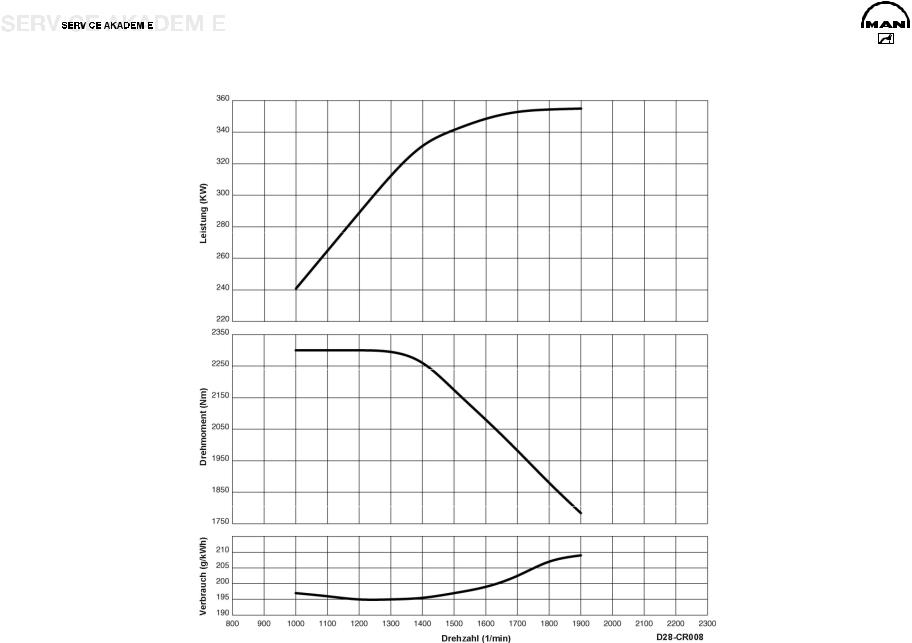
A TORQUE C SPECIFIC FUEL CONSUMPTION
Power and torque increase with speed. After overcoming the friction loss and greater heat losses at low speeds, the engine achieves its maximum torque with optimum filling of the cylinder. If speed increases further, the torque drops because of the greater flow resistance and short valve opening times.
The full-load consumption curve in the diagram can be explained by the fact that you get less than good fuel consumption in the low range of speed because of the poor pressure mix of the fuel particles (14.5:1). At high speeds, combustion is imperfect because of the short time that is available. And fuel consumption increases.
B POWER
Power is the product of speed and torque. Seeing as the drop in torque is slower than the increase in speed, there is initially an increase if the power output of an engine. Between the maximum torque and the maximum power there is an elastic range in which power is kept constant by increasing torque although the speed is dropping.
|
D:AutoTRUCKMANMAN SeriesДвигатель_Топливная системаДвигателиenD2876_CR_eng.doc |
Page 14 |

|
D:AutoTRUCKMANMAN SeriesДвигатель_Топливная системаДвигателиenD2876_CR_eng.doc |
Page 15 |

TECHNICAL DATA
|
D 2876 LF 12 Euro 3 |
|||
|
Model…………………………………………………….. |
R6 TI-EDC (4 V) |
Idling speed …………………………………………………….. |
600 1/min |
|
Cylinder arrangement…………………………….. |
6 cylinders inline |
Valve play on cold engine………………………………… |
IV 0.50 mm |
|
Max. power …………………………………………….. |
353 kW / 480 hp |
Valve play exhaust with EVB ………….. |
EV 0.80 mm / 0.60 mm |
|
Rated speed ………………………………………………….. |
1900 1/min |
Compression pressure…………………………………………. |
> 28 bar |
|
Max. torque……………………………………………………….. |
2300 Nm |
Admissible pressure difference between cylinders..max. 4 bar |
|
|
Speed at max. torque…………………………… |
1000 to 1300 1/min |
Coolant ………………………………………………….. |
50 (I/R 58) liters |
|
Capacity………………………………………………………… |
12,816 cm3 |
Oil charge ………………………………………………………….. |
42 liters |
|
Bore / stroke ……………………………………………………… |
128 / 166 |
Fuel system………………………………………………… |
Bosch EDC 7 |
|
Ignition sequence …………………………………………… |
1-5-3-6-2-4 |
Fan coupling actuation…………………………………. |
hydroelectric |
|
Cylinder 1 location………………………………………………. |
fan side |
Weight (dry) with WR…………………………………………… |
1071 kg |
|
Combustion process, injector …………………………………….. |
7-jet |
K factor………………………………………………………………… |
1.3 m-1 |
|
Compression……………………………………………………………….. |
18 |
|
D:AutoTRUCKMANMAN SeriesДвигатель_Топливная системаДвигателиenD2876_CR_eng.doc |
Page 16 |
|
D:AutoTRUCKMANMAN SeriesДвигатель_Топливная системаДвигателиenD2876_CR_eng.doc |
Page 17 |

|
D 2876 LF 13 Euro 3 |
||||||||
|
Model…………………………………………………….. |
R6 TI-EDC (4 V) |
Idling speed …………………………………………………….. |
600 1/min |
|||||
|
Cylinder arrangement…………………………….. |
6 cylinders inline |
Valve play on cold engine………………………………… |
IV 0.50 mm |
|||||
|
Max. power …………………………………………….. |
390 kW / 530 hp |
Valve play exhaust with EVB ………….. |
EV 0.80 mm / 0.60 mm |
|||||
|
Rated speed ………………………………………………….. |
1900 1/min |
Compression pressure…………………………………………. |
> 28 bar |
|||||
|
Max. torque……………………………………………………….. |
2400 Nm |
Admissible pressure difference between cylinders..max. 4 bar |
||||||
|
Speed at max. torque…………………………… |
1000 to 1400 1/min |
Coolant ………………………………………………….. |
50 (I/R 58) liters |
|||||
|
Capacity………………………………………………………… |
12,816 cm3 |
Oil charge ………………………………………………………….. |
42 liters |
|||||
|
Bore / stroke ……………………………………………………… |
128 / 166 |
Fuel system………………………………………………… |
Bosch EDC 7 |
|||||
|
Ignition sequence …………………………………………… |
1-5-3-6-2-4 |
Fan coupling actuation…………………………………. |
hydroelectric |
|||||
|
Cylinder 1 location………………………………………………. |
fan side |
Weight (dry) without WR………………………………………. |
1049 kg |
|||||
|
Combustion process, injector …………………………………….. |
7-jet |
K factor………………………………………………………………… |
1.3 m-1 |
|||||
|
Compression……………………………………………………………….. |
18 |
|
D:AutoTRUCKMANMAN SeriesДвигатель_Топливная системаДвигателиenD2876_CR_eng.doc |
Page 18 |

|
D:AutoTRUCKMANMAN SeriesДвигатель_Топливная системаДвигателиenD2876_CR_eng.doc |
Page 19 |

ENGINE BLOCK – CRANK CASE
The crank case is cast in one piece together with the cylinder block from special GJL-250 cast iron. The wet cylinder liners of highly wear-resistant, special centrifugal cast GJL-250 are exchangeable. The sealing between the cylinder liner and the crank case coolant jacket at the top is by a oval elastomer moulded washer and at the bottom by two elastomer round sealing rings.
Optimized wall thicknesses and functional ribbing of the crank case side walls optimized by the finite element method (FEM) produce rigidity of form and low noise emission.
The crank case was matched to the higher ignition pressure (160 instead of 145 bar) by reinforcing the partitions and geometrically optimizing the cylinder liner fitting, but for the same crank case weight.
To improve the oil supply to the valve gear, extra oil holes were provided in the crank case across from the main oil duct through the partitions to the cam shaft bearing (and on to the valve gear).
The crank case was matched externally for compact attachment of the new EDC 7 control unit, rail and cam shaft engine speed sensor. The casting and machining of the crank case were also optimized.
The crank case is closed off at the rear by the flywheel/timing case of GJS-400 ductile cast iron, with the rear crank shaft sealing ring, and at the bottom by the crank case yoke of permanent mould cast aluminium (Loctite 518 sealing). Apply a track with a maximum width of 1 mm.
The crank case venting gases are fed back into the combustion air by way of a wire-knit oil trap with pressure regulating valve attached to the rear left of the crank case to avoid emission on the intake side of the turbo charger.
|
D:AutoTRUCKMANMAN SeriesДвигатель_Топливная системаДвигателиenD2876_CR_eng.doc |
Page 20 |
![]()
|
D:AutoTRUCKMANMAN SeriesДвигатель_Топливная системаДвигателиenD2876_CR_eng.doc |
Page 21 |

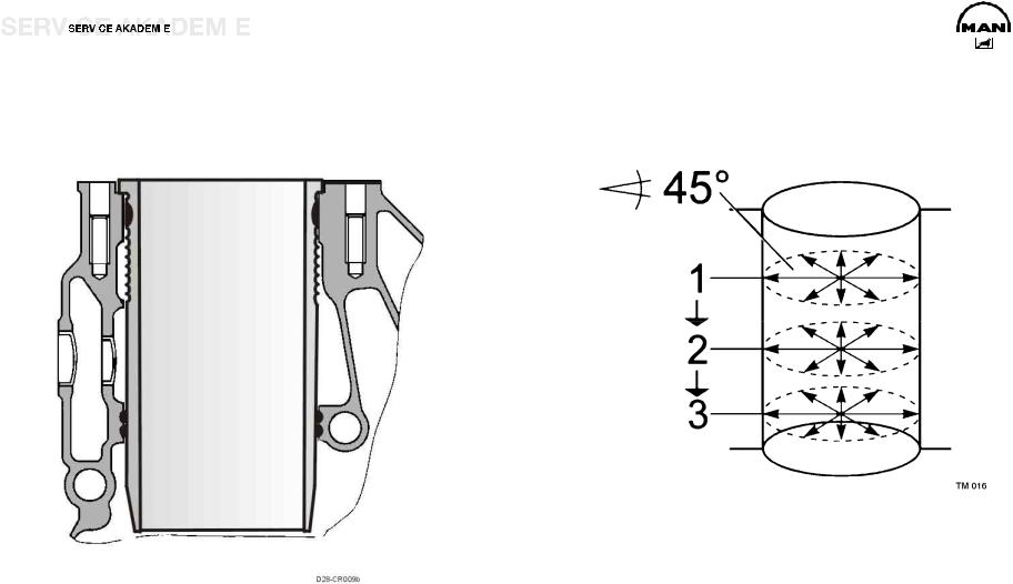
CYLINDER LINERS
The wet, exchangeable cylinder liners are produced from a special centrifugal cast iron.
The oval O-ring (1) for the upper packing must be inserted without any twist in the second grooves of the liner.
Lightly coat the cylinder liner in the region of the upper O-ring with engine oil.
Place new O-rings (2) in the crank case (Viton).
Lightly coat the region of the lower O-ring with engine oil, as well as the transition of the cylindrical part of the bush.
Caution:
Do NOT use a brush!
NOTE:
The packing of the cylinder liners is different.
NOTE:
DO NOT USE ANY KIND OF GREASE / SEALANT.
Method for measuring cylinder liner projection (without the sealing ring). Place cylinder liners in the crank case without an O-ring.
Attach a press-on gauge plate and tighten to 40 Nm. Then measure at at least four points with the dial gauge.
1Cylinder liner
2Crank case
CRim depth in crank case
DRim height of cylinder liner
D-C Projection of liner from crank case
Cylinder liner projection: min 0.035 mm, max. 0.1 mm
|
Rim depth |
C |
7.965 to 8.015 mm |
|
Rim height of cylinder liner |
D |
8.05 to 8.07 mm |
|
D:AutoTRUCKMANMAN SeriesДвигатель_Топливная системаДвигателиenD2876_CR_eng.doc |
Page 22 |

|
D:AutoTRUCKMANMAN SeriesДвигатель_Топливная системаДвигателиenD2876_CR_eng.doc |
Page 23 |

PISTON PLAY – CYLINDER LINERS
Measurement of piston play:
Measure the inner diameter of the cylinder liners with an inside micrometer at three levels from top to bottom, and radially at intervals of 45°. Read the piston diameter from the bottom of new pistons. On pistons that have run, measure with an outer micrometer from the piston bottom edge across the piston axis. Subtract the piston diameter from the largest measured cylinder liner diameter.
The figure arrived at is the piston play.
NOTE:
If the piston play is too large, replace the cylinder bush and piston.
|
Example of piston play for D 28..LF |
|
|
Cylinder diameter……………………………….. |
127.99 to 128.01 mm |
|
Piston diameter………………………………. |
127.561 to 127.570 mm |
|
Ideal play …………………………………………………. |
0.14 to 0.15 mm |
|
Wear limit……………………………………………………………. |
0.30 mm |
Measure on 3 position, for example 1,2,3
|
D:AutoTRUCKMANMAN SeriesДвигатель_Топливная системаДвигателиenD2876_CR_eng.doc |
Page 24 |
|
D:AutoTRUCKMANMAN SeriesДвигатель_Топливная системаДвигателиenD2876_CR_eng.doc |
Page 25 |

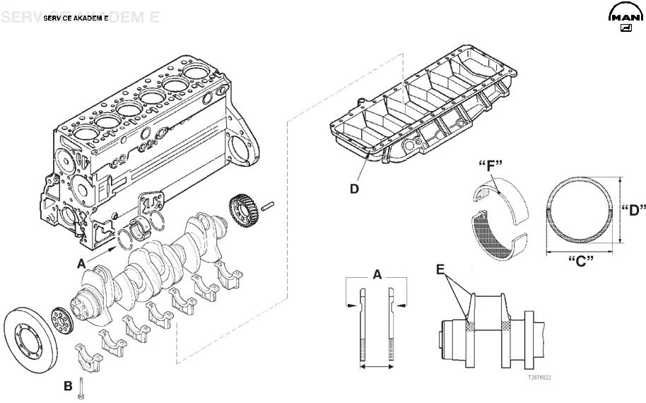
CRANK SHAFT
The crank shaft has a 7-point bearing and eight forged-on counterweights to balance inertial forces. The main and big-end bearing pins as well as the lapped bearing collars are induction hardened and ground.
ON A CRANK SHAFT N1, ALL BIG-END OR MAIN BEARING PINS ARE IN EVERY CASE ALSO N1.
The axial bearing of the crank shaft is implemented by thrust washers on the middle bearing block.
Attention: The oil flutes of the thrust washers A must face the crank webs.
Attention: Never dismantle the vibration damper using a hammer or fitter’s lever. The slightest dent will ruin the damping function of the vibration damper. This can cause clutch damage and breakage of the crank shaft.
|
A |
Axial bearing of crank shaft………… |
0.190 to 0.312 mm |
|
Wear limit……………………………………………………. |
max. 1.25 mm |
|
|
B |
Main bearing bolts……………………………… |
300 Nm + 90° |
DCrank case yoke to reinforce crank case Use 04.10394-9272 sealant.
EDesignation H and P tolerance N or N1 of big-end or main bearing pins (N1= 0.1 mm deviation)
Spread of bearing shells F:
Measure dimension C.
Measure dimension D.
Expansion = C minus D
Spread must be between 0.3 and 1.2 mm.
Attention: C must be greater than D.
|
Main bearing pin diameter ……………….. |
N 103.98 to 104.00 mm |
|
Main bearing inner diameter…………. |
N 104.066 to 104.112 mm |
|
Other undersizes……………… |
0.25 to 0.50 mm, 0.75 to 1.00 mm |
|
D:AutoTRUCKMANMAN SeriesДвигатель_Топливная системаДвигателиenD2876_CR_eng.doc |
Page 26 |
|
D:AutoTRUCKMANMAN SeriesДвигатель_Топливная системаДвигателиenD2876_CR_eng.doc |
Page 27 |

Crank shaft lining front and rear
On the rear crank shaft lining, like on the front, rotary shaft seals of polytetrafluorethylene (PTFE), trade name Teflon, are always used.
Because of its own relatively large initial tension, the lip (A) tends to curve inwards. For this reason the PTFE lining ring is supplied on a transport wrapper (B). It must be left on this wrapper until it is used. Another reason for this is that the lip is very sensitive and the slightest damage can result in leakage. The sealing lip and the race of the flywheel must not be coated with oil or other lubricants.
NOTE:
New engines come without a race.
When repairing, only use variants with a race (04.10160-9049 sealant).
Fitting notes:
The PTFE lining ring must be fitted absolutely free of oil
and grease. The slightest oil or grease traces on the race or lining ring can result in leakage.
Before fitting, clean any oil, grease and anti-corrosion agents off the race and pull-in tool. You can use any conventional cleaning agent for this purpose.
Never store the PTFE lining ring without the supplied transport wrapper. After only about 20 min without the wrapper it will lose its initial tension and is then unusable.
|
D:AutoTRUCKMANMAN SeriesДвигатель_Топливная системаДвигателиenD2876_CR_eng.doc |
Page 28 |
|
D:AutoTRUCKMANMAN SeriesДвигатель_Топливная системаДвигателиenD2876_CR_eng.doc |
Page 29 |

Pull out the rotary shaft seal
Loosen the lining ring by tapping it.
Use the extractor tool
Slide the four hooks under the lip, turn through 90° so that they grip the ring behind the lip, and pull out the rotary shaft seal by turning the spindle.
Attach the race
The latest crank shafts come without races. A race is fitted when renewing the crank shaft sealing ring.
Clean the inside of the race and crank shaft stump, and coat the crank shaft stump with 04.10160-9049 sealant. Slide the race and press-fit sleeve onto the adapter. Tighten the spindle in the adapter with the nut. Screw the adapter tightly to the crank shaft. The adapter must fit tightly on the crank shaft to ensure the correct press-fit depth of the race. Pull in the race as far as the stop of the press-fit sleeve.
Fit the rotary shaft seal
Screw the adapter to the crank shaft.
Clean the adapter and the race. The rotary shaft seal must be
assembled dry. Do not coat the lips with oil or other
lubricants.
Place the rotary shaft seal with the transport wrapper on the adapter and slide the seal onto the adapter.
Remove the transport wrapper.
Slide the winding sleeve onto the adapter.
Screw the spindle into the adapter.
Pull in the rotary shaft seal as far as the stop of the winding sleeve on the end cover.
|
D:AutoTRUCKMANMAN SeriesДвигатель_Топливная системаДвигателиenD2876_CR_eng.doc |
Page 30 |
![]()
|
D:AutoTRUCKMANMAN SeriesДвигатель_Топливная системаДвигателиenD2876_CR_eng.doc |
Page 31 |

FLYWHEEL
The flywheel is centered on the crank shaft by a set pin and
attached by ten torque screws.
Tightening method for flywheel screws
Anti-fatigue screws M16 x 1.5 (12.9)
Pretighten to 100 Nm.
Turn 900.
Tighten finally by turning 90°.
NOT reusable
Caution:
Make sure the race (2) is properly seated.
Use 04.10160-9049 sealant.
Place the faced side first and use a mandrel to push it right on. Coat the seat of the race with green Omnifit.
Clutch shaft guide bearing (1)
|
D:AutoTRUCKMANMAN SeriesДвигатель_Топливная системаДвигателиenD2876_CR_eng.doc |
Page 32 |

|
D:AutoTRUCKMANMAN SeriesДвигатель_Топливная системаДвигателиenD2876_CR_eng.doc |
Page 33 |

Machining of flywheel
In the event of heavy scoring, the permissible material wear of the press-on surface is max. 1,6 mm.
Minimum dimension A: 60.5 mm
Standard dimension A: 62 ±0.1 mm
Maximal lateral runout of starter rim: 0.5 mm
Outer diameter of flywheel: 488 to 487.8 mm
The starter rim is heated to between 200 and 230°C for
assembly.
|
D:AutoTRUCKMANMAN SeriesДвигатель_Топливная системаДвигателиenD2876_CR_eng.doc |
Page 34 |

|
D:AutoTRUCKMANMAN SeriesДвигатель_Топливная системаДвигателиenD2876_CR_eng.doc |
Page 35 |

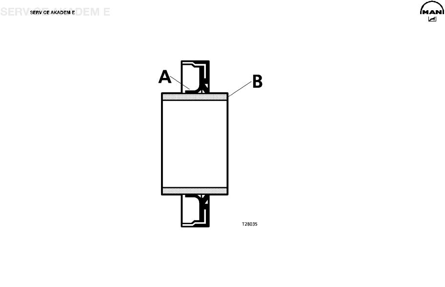
CONNECTING ROD
The connecting rods are drop-forged from heat-treatable C38mod steel, without weight compensating battens, and split obliquely by cracking the bearing cap. The oblique split simplifies assembly and repair, because the connecting rods can be taken out through the top of the cylinders.
The big-end bearings are designed for extremely high stress and long service life. The upper bearing shell consists of highly wear-resistant sputter metal. There is a long oil hole from the large to the small connecting rod eye for proper supply of oil to the latter.
Measurement of big-end bearing
Measure the inner bore of the big-end bearing shells in an assembled state on the axes 1, 2 and 3 and at levels a and b. Bearing shells whose bore is within tolerance limits can be reused, if they are outside you must renew the bearing.
Scrap them if the bore is larger or oval.
NOTE:
The top bearing shell is marked TOP or has a red spot on the side (tempered backing shell).
|
Big-end bearing pin dia. (standard)………. |
89.980 to 90.000 mm |
|
Big-end bearing inner dia. (standard)……. |
90.060 to 90.102 mm |
|
Big-end bearing spread (Miba) ……………………. |
95.5 to 96.4 mm |
|
Big-end bearing radial play……………………… |
0.060 to 0.122 mm |
|
Spread C………………………………………………….. |
95.5 to 96.4 mm |
Tightening torque of connecting rod screws:
100 Nm+10 + 90°+10
Connecting rod screws: M14 x 1.5 x 65/10.9 Torx
Re-use of the screws is not permissible.
Caution:
Do NOT place the connecting rod or the cover on the seam. Any damage (change) to the structural fracture will destroy it.
|
D:AutoTRUCKMANMAN SeriesДвигатель_Топливная системаДвигателиenD2876_CR_eng.doc |
Page 36 |

|
D:AutoTRUCKMANMAN SeriesДвигатель_Топливная системаДвигателиenD2876_CR_eng.doc |
Page 37 |

PISTONS
The three-ring pistons are of a special cast aluminium with a moulded ring insert for the uppermost piston ring. The combustion chamber is slightly retracted, graduated and omega-shaped. There are valve recesses on the inlet and outlet side. To reduce the effects of heat, the pistons have a cast integral cooling duct and are cooled by an oil jet from injection nozzles.
The pistons were adapted to the higher ignition pressures by graduated bracing of the connecting rod, suitable selection of materials and appropriate scaling of the combustion chamber.
The oil injection nozzles in the crank case are matched in their flow cross-section to the new cooling duct of the pistons. The oil pressure valve in the injection nozzles is omitted to ensure proper piston cooling also at low engine speeds.
A new, smooth piston pin of larger diameter is used to take load off the piston pin boss.
Rings
Double-faced trapezoidal ring and second compression ring as compression rings, ventilated oil scraper ring with spiral expander and bevelled outer edges.
Piston projection under/over top edge of crank case:
-0.03 to +0.331 mm
Gap of piston rings, wear limit
I Trapezoidal ring, wear limit 1.5 mm
II Second compression ring, wear limit 1.5 mm III Oil scraper ring, wear limit 1.5 mm
|
D:AutoTRUCKMANMAN SeriesДвигатель_Топливная системаДвигателиenD2876_CR_eng.doc |
Page 38 |

|
D:AutoTRUCKMANMAN SeriesДвигатель_Топливная системаДвигателиenD2876_CR_eng.doc |
Page 39 |

Pistons (technical data from Kolben Schmidt)
1Piston diameter, measured across boss:
KS measured 20 mm
|
above piston bottom edge (2)……… |
127.561 to 127.570 mm |
|
4 Compression height: |
|
|
Standard dimension: D 2876 LF……………………… |
79.25 mm |
Undersize: 0.2 mm / 0.4 mm / 0.6 mm
APiston projection under/over crank case top edge:
— 0.03 to +0.30 mm
|
Piston ring flutes |
||
|
(5) |
Compression ring 1 |
…………………………………..4 to 4.05 mm |
|
(6) |
Compression ring 2 ……………………………… |
3.04 to 3.06 mm |
|
(7) |
Oil scraper ring…………………………………… |
4.04 to 4.06 mm |
|
Piston ring height |
|
|
Double-faced trapezoidal compression ring |
|
|
Height………………………………………………. |
3.99 to 4.025 mm |
|
Gap……………………………………………………. |
0.35 to 0.55 mm |
|
Second compression ring …………………………….. |
2.97 to 3.0 mm |
|
Gap……………………………………………………….. |
0.7 to 0.9 mm |
|
Oil scraper ring |
|
|
KS……………………………………………………. |
3.975 to 3.99 mm |
|
Gap……………………………………………………. |
0.25 to 0.55 mm |
|
Piston weight difference per engine set…………………. |
max. 50 g |
Fit with arrow pointing to the frontend
|
D:AutoTRUCKMANMAN SeriesДвигатель_Топливная системаДвигателиenD2876_CR_eng.doc |
Page 40 |
![]()
|
D:AutoTRUCKMANMAN SeriesДвигатель_Топливная системаДвигателиenD2876_CR_eng.doc |
Page 41 |

ENGINE CONTROL
Setting of timing
The marking of the crank shaft gear must match with the marking of the shrink-fit cam shaft gear (not the same as TDC of cylinder 1).
|
A |
Gear wheels on flywheel side |
B |
Gear wheels on fan side |
|
1 |
Crank shaft |
8 |
Cam shaft wheel |
|
2 |
Oil pump drive |
9 |
Compressor drive gear |
|
3 |
Oil pump delivery wheels |
10 |
Fan drive gear |
4Cam shaft
5Intermediate gear for high pressure pump
6High pressure pump drive
7Auxiliary drive
|
D:AutoTRUCKMANMAN SeriesДвигатель_Топливная системаДвигателиenD2876_CR_eng.doc |
Page 42 |

|
D:AutoTRUCKMANMAN SeriesДвигатель_Топливная системаДвигателиenD2876_CR_eng.doc |
Page 43 |

CAM SHAFT
The cam shaft is forged from Cf53 steel with induction hardened and ground cams and bearing points. It is seated in the crank case with a 7-point bearing in white metal bushes. The axial bearing of the cam shaft takes the form of a collar end bearing in the crank case on bearing 7. In the timing case there is a butting ring screwed in as an axial stop.
Engines with cam shaft power takeoff are fitted with a specially forged shaft of carburizing 16MnCr5 steel with a highly wearresistant, sputter collar end bearing 7 in the crank case.
The cam shaft is driven from the crank shaft by case-hardened, helically toothed spur wheels on the rear side of the engine. Bolted at the back of the cam shaft is also the drive wheel for high-pressure pump CP3.4 (M10 x 35 10.9 Nm 65). This gear wheel bears markings for the cam shaft engine speed sensor. Valve lifter lubricant paste 09.15011-0011.
A spur wheel is fitted to the front end of the cam shaft to drive the air compressor and the fan shaft.
1Reference markers to identify first cylinder
2High-pressure pump drive wheel
3Cam shaft drive wheel
4Retaining screw 65 Nm
5Oil hole
|
D:AutoTRUCKMANMAN SeriesДвигатель_Топливная системаДвигателиenD2876_CR_eng.doc |
Page 44 |

|
D:AutoTRUCKMANMAN SeriesДвигатель_Топливная системаДвигателиenD2876_CR_eng.doc |
Page 45 |

|
Admissible play of cam shaft |
|||||||
|
Cam shaft axial play ………………………………… |
0.20 to 0.90 mm |
||||||
|
Wear limit …………………………………………………………. |
1.50 mm |
||||||
|
Test without the air compressor attached. |
|||||||
|
NOTE: |
For cam shaft power takeoff, the cam shaft is held reinforced between bearings 6 and 7 and in a highly wear-resistant, special collar end bearing on bearing 7.
Tightening torque:
Screws for butting ring 40 Nm
Secure with Loctite 648.
Measure the axial play of the cam shaft.
Press the cam shaft tightly against the crank case.
Add the seal thickness z = 0.5 mm to dimension y.
Cam shaft axial play = y + z — x
Dimension x = margin of sealing face of crank case to butting face of cam shaft drive wheel
Dimension y = margin of sealing face of timing case to butting ring
Dimension z = thickness of seal pressed
1Crank case
2Gauge rail
3Cam shaft gear wheel
4Sealing face of crank case
5Sealing face of timing case
6Butting ring
7Timing case
|
D:AutoTRUCKMANMAN SeriesДвигатель_Топливная системаДвигателиenD2876_CR_eng.doc |
Page 46 |

|
D:AutoTRUCKMANMAN SeriesДвигатель_Топливная системаДвигателиenD2876_CR_eng.doc |
Page 47 |

CHECK OF VALVE TIMING
Check the timing for the specified valve cycle.
Twisting of the shrink-fit cam shaft drive wheel can result in serious engine damage.
Consequently, after engine malfunctions that can cause such twisting, e.g. failure of the air compressor, make sure seating is correct by checking the valve timing.
Requirement: push roads must not be bent.
|
D 2876 LF 12 |
0.50 IV / 0.60 |
EV / 0.40 EVB Valve play |
|
Valve travel |
9.0 to 9.5 mm |
|
|
D 2876 LF 13 |
0.50 IV / 0.60 |
EV / 0.40 EVB Valve play |
|
Valve travel |
9.0 to 9.5 mm |
Proceed as follows:
Attach the engine turning gear to the timing case.
Remove the cylinder head.
Correctly set the inlet and exhaust valves.
Set the flywheel to TDC so that the valves overlap.
Place the dial gauge with approx. 11 mm advance on the disk of the inlet valve on the 4th cylinder and set to «O».
Turn the engine in the running direction (left) until the dial gauge pointer no longer moves.
If the timing is correct, the figures shown on the dial gauge must be within the following tolerances. Read the valve travel from the dial gauge.
.
|
D:AutoTRUCKMANMAN SeriesДвигатель_Топливная системаДвигателиenD2876_CR_eng.doc |
Page 48 |

|
D:AutoTRUCKMANMAN SeriesДвигатель_Топливная системаДвигателиenD2876_CR_eng.doc |
Page 49 |

Timing
|
Timing D 2876 LF 12/13 |
Timing diagram |
|||
|
Inlet opens |
23° before TDC |
Degrees referred to crank shaft angle |
||
|
Inlet closes |
12° after BDC |
|||
|
Exhaust opens |
60° before BDC |
1 = |
Direction of engine turning |
|
|
Exhaust closes |
30° after TDC |
2 |
= |
Inlet opens |
|
3 |
= |
Inlet closes |
||
|
4 |
= |
Inlet opening time |
||
|
5 |
= |
Center inlet cam |
||
|
6 |
= |
Exhaust opens |
||
|
7 |
= |
Exhaust closes |
||
|
8 |
= |
Exhaust opening time |
||
|
9 |
= |
Center exhaust cam |
|
D:AutoTRUCKMANMAN SeriesДвигатель_Топливная системаДвигателиenD2876_CR_eng.doc |
Page 50 |
 Loading…
Комментировать
Прокомментировать


Подтвердите, что Вы не робот:*
![]()
Искандер
Гости
17 сентября 2021 22:39
0
Спасибо, очень поможет мне в дальнейшем.
- Ответить
- Цитата
![]() Скачать бесплатно руководства по ремонту автомобилей в PDF формате
Скачать бесплатно руководства по ремонту автомобилей в PDF формате
Электронные книги : Руководства по ремонту, советы по эксплуатации, ремонту двигателей и электрооборудования, технические характеристики различных марок автомобилей
Скачать бесплатно электронные книги , инструкции и руководства по ремонту автомобилей, книги по ремонту и эксплуатации автомобилей, и другие автокниги, а также автокаталоги, карты, атласы, учебные пособия для подготовки водителей, CD диски по автомобильной тематике, каталоги запчастей для автомобилей, автокниги по ремонту, эксплуатации и обслуживанию автомобилей, как российских, так и зарубежных производителей, издательств технической литературы, таких как Третий Рим, Арус, Монолит, Мир Автокниг, За рулем, Легион Автодата
Acura, Alfa Romeo, Audi, Beifan Benchi, BMW, Buick, BYD, Cadillac, Chery, Chevrolet, Chrysler, Citroen, Dacia, Dadi, Daewoo, DAF, Daihatsu, Derways, Dodge, Dong Feng, FAW, Fiat, Ford, Foton, Freightliner, Geely, GMC, Great Wall, Groz, Hania, Hino, Holden, Honda, HOWO, Hummer, Hyundai, Infiniti, International, Iran, Isuzu, Iveco, Jeep, Kenworth, Kia, Lancia, Land Rover, Range Rover, Lexus, Lifan, Lincoln, MAN, Maxus, Mazda, Mercedes-Benz, Mercury, Mini, Mitsubishi, Nissan, Oldsmobile, Opel, Peterbilt, Peugeot, Plymouth, Pontiac, Porsche, Renault, Rover, Saab, Samsung, Saturn, Scania, Scion, Seat, Setra, Shaanxi, Skoda, SsangYong, Subaru, Suzuki, TagAZ, Tata, Toyota, VolksWagen, Volvo, Vortex, ZAZ, АЗЛК, Москвич, ВАЗ, Lada, ГАЗ, Донинвест, ЗИЛ, Иж, КамАЗ, КрАЗ, ЛиАЗ, ЛуАЗ, МАЗ, МЗКТ, ПАЗ, УАЗ, УРАЛ
Книга: MAN TGX / TGS дизель с 2007 г.в., ремонт, эксплуатация, техническое обслуживание
Руководство по эксплуатации и техническому обслуживанию грузовых автомобилей Man TGX / TGS с 2007 года выпуска с дизельными двигателями D20; D26; D28.
Книга: MAN TGX / TGS дизель с 2007 г.в., эксплуатация, каталог деталей
Руководство по эксплуатации + каталог деталей MAN TGX / TGS с двигателями D2066 и D2676 EURO 4/5.
Книга: MAN TGL / TGM дизель с 2005 г.в., ремонт, эксплуатация, техническое обслуживание
Руководство по эксплуатации и техническому обслуживанию грузовых автомобилей Man TGL / TGM с 2005 года выпуска с дизельными двигателями D0834; D0836.
Книга: MAN TGA дизель с 2000 / 2005 г.в., ремонт, эксплуатация, техническое обслуживание
Руководство по эксплуатации и техническому обслуживанию грузовых автомобилей Man TGA с 2000 года выпуска с дизельными двигателями D2066; D2865; D2866; D2876.
Книга + CD: MAN TGA дизель с 2000 г.в., ремонт, эксплуатация, техническое обслуживание + каталог деталей
Подробный комплект материалов по ремонту и обслуживанию автомобиля MAN TGA с 2000 года выпуска с дизельными моторами: 6.9D, 10.5D, 12.0D, 12.4D, 12.8D, 18.3D л.
Книга: MAN L2000 / LE2000 / M2000L / M2000M / ME2000 / F90 / M90 / F2000 дизель ремонт, эксплуатация, техническое обслуживание
Самое подробное пособие по ремонту и техническому обслуживанию грузовых автомобилей Man L2000 / LE2000 / M2000L / M2000M / ME2000 / F90 / M90 / F2000 с дизельными двигателями D02, D08, D25, D28.
Книга: MAN 19 дизель ремонт, техническое обслуживание
Руководство по ремонту и техническому обслуживанию грузовых автомобилей Man модели 19.292, 19.332, 19.362 с двигателями объемом 12 литров.
Книга: MAN 19 дизель ремонт, техническое обслуживание
Руководство по ремонту и техническому обслуживанию грузовых автомобилей Man модели 19.292, 19.332, 19.362 с двигателями объемом 12 литров.
Книга: MAN M90 / M2000 дизель ремонт, эксплуатация, техническое обслуживание
Руководство по ремонту и эксплуатации грузовых автомобилей MAN M90 / M2000. Каталог деталей двигателей.
Книга: MAN M90 / M2000 дизель устройство каталог деталей
Руководство по устройству грузовых автомобилей MAN M90 / M2000. Каталог деталей.
Книга: MAN F90 / F2000 дизель устройство каталог деталей
Руководство по устройству грузовых автомобилей MAN F90 / F2000. Книга содержит каталог деталей и сборочных единиц автомобиля.
Книга: MAN F90 / F2000 дизель ремонт, эксплуатация, техническое обслуживание
Руководство по ремонту и эксплуатации грузовых автомобилей MAN F90 / F2000. Электросхемы.
Книга: MAN TGA дизель 2000-2008 г.в., ремонт, техническое обслуживание электросхемы
Руководство по ремонту и техническому обслуживанию грузовых автомобилей Man TGA 2000-2008 годы выпуска. В книге представлены подробные электрические схемы.
Книга: MAN TGL дизель эксплуатация, техническое обслуживание каталог деталей
Руководство по эксплуатации и техническому обслуживанию автомобилей MAN TGL. Книга содержит каталог деталей и сборочных единиц автомобиля, включая двигатели MAN D0834 и MAN D0836 различных модификаций.
Книга: MAN TGA дизель эксплуатация, каталог деталей
Руководство по эксплуатации и техническому обслуживанию автомобилей Man TGA. Книга содержит каталог деталей и сборочных единиц автомобиля. В книге представлена инструкция по эксплуатации Man TG-A, а также рекомендации по техническому обслуживанию автомобиля.
Книга: MAN L2000 дизель рем
Руководство по ремонту грузового автомобиля MAN L2000.
Книга: MAN M90 дизель эксплуатация,
Руководство по эксплуатации грузовых автомобилей MAN M90.
Книга: MAN M90 дизель ремонт, Часть 2
В издании описывается ремонт сцепления, КПП, мостов, рулевого управления, тормозной системы, подвесок, электрооборудования и кузова устанавливающихся на автомобили MAN M90.
Книга: MAN M90 дизель ремонт, Часть 1
В издании описывается ремонт дизельных двигателей серии DO 826 (F, FO1, TF, LF01, LF, LF02) устанавливающихся на автомобили MAN M90.
Книга: MAN F90 / F2000 дизель ремонт, техническое обслуживание
Руководство по ремонту грузовых автомобилей Man F 90 / F 2000 серий 19.273, 293, 323, 343, 373, 403, 423, 463, 23.343, 26.373, 403, 423, 463, с двигателями D2555, D2556, D2565, D2566, D2865, D2866, D2876 рабочим объемом 9,2; 9,5; 11,0; 11,4; 12,0; 12,8 л.
Книга: MAN TGA дизель рем
Руководство по ремонту грузовых автомобилей MAN TG-A.
Книга: MAN TGA дизель эксплуатация,
Руководство по эксплуатации и техническому обслуживанию грузовых автомобилей Man TGA.
Книга: MAN TGL дизель эксплуатация, техническое обслуживание
Руководство по эксплуатации и техническому обслуживанию грузовых автомобилей MAN TGL.
Книга: MAN F2000 дизель эксплуатация, техническое обслуживание
Руководство по эксплуатации и обслуживанию нескольких выпусков большегрузных автомобилей фирмы MAN третьего (и частично 4-го) поколения, тяжелой серии F-2000, подробно описано техническое обслуживание всех систем, даны рекомендации по поиску возможных неисправностей ряда систем.
Книга: MAN M2000 дизель рем
Руководство по ремонту грузовых автомобилей MAN M 2000 с двигателя D0824 LFL06, D0826 LFL03, LFL09, LF15, LF17 рабочим объемом 4,6 и 6,9 л
- Manuals
- Brands
- Man Manuals
- Engine
ManualsLib has more than 114 Man Engine manuals
Click on an alphabet below to see the full list of models starting with that letter:
B
D
E
V
Popular manuals
138 pages
D 2866 LE 401 Repair Manual
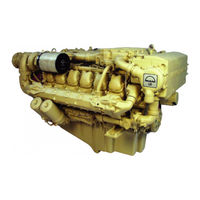
194 pages
D 2840 LE 301 Repair Manual
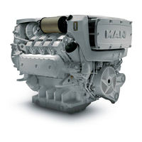
133 pages
D2868 LE433 Operating Instructions Manual
584 pages
D 28 Series Operator And Maintenance Manual
354 pages
B&W S80ME-C7 Project Manual

338 pages
B&W S50ME-B9.3-TII Project Manual
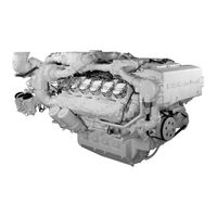
71 pages
D 2840 LE 403 Operating Instructions Manual
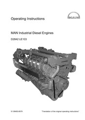
90 pages
D2842 LE103 Operating Instructions Manual

404 pages
B&W S50MC-C8-TII Project Manual
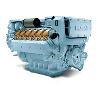
134 pages
V8-1000 Installation And Operating Instructions Manual

376 pages
B&W L35MC6-TII Project Manual
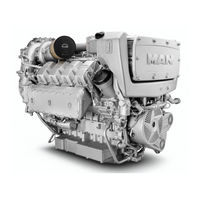
40 pages
D 2868 Maintenance Schedule
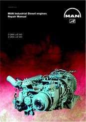
174 pages
D 2866 LUE 605 Repair Manual
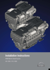
92 pages
V8-1200 Installation Instructions Manual
136 pages
E0834 E302 Maintenance Manual
118 pages
E3268 LE212 Operating Instructions Manual
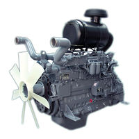
16 pages
D 2876 LE 201 Repair Manual
6 pages
D 2842 LE 409 Repair Manual
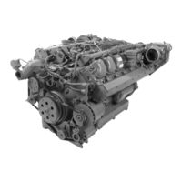
50 pages
D2842 LE602 Operating Instructions Manual
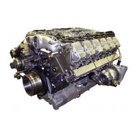
180 pages
D 2842 LE 620 Repair Manual
Models
Document Type
B
B&W L35MC6-TII

Project Manual
B&W S50MC-C8-TII
Project Manual
B&W S50ME-B9.3-TII
Project Manual
B&W S80ME-C7
Project Manual
D
D 08 Series
Operator And Maintenance Manual
D 0824 LFL
Operator And Maintenance Manual
D 0824 LOH
Operator And Maintenance Manual
D 0826 LF
Operator And Maintenance Manual
D 0826 LFL
Operator And Maintenance Manual
D 0826 LOH
Operator And Maintenance Manual
D 0826 LUH
Operator And Maintenance Manual
D 0834 LFL
Operator And Maintenance Manual
D 0834 LOH
Operator And Maintenance Manual
D 0836 LF
Operator And Maintenance Manual
D 0836 LFL
Operator And Maintenance Manual
D 0836 LOH
Operator And Maintenance Manual
D 0836 LUH
Operator And Maintenance Manual
D 28 Series
Operator And Maintenance Manual
D 2840 LE 301
Repair Manual
D 2840 LE 403
Operating Instructions Manual
D 2840 LF
Operator And Maintenance Manual
D 2842 LE 301
Repair Manual
D 2842 LE 404
Operating Instructions Manual
D 2842 LE 407
Operating Instructions Manual
D 2842 LE 409
Repair Manual
D 2842 LE 410
Operating Instructions Manual
D 2842 LE 414
Operating Instructions Manual
D 2842 LE 415
Operating Instructions Manual
D 2842 LE 416
Operating Instructions Manual
D 2842 LE 417
Operating Instructions Manual
D 2842 LE 620
Repair Manual
D 2842 LF
Operator And Maintenance Manual
D 2862
Maintenance Schedule
D 2866 E
Operating Instructions Manual
D 2866 LE
Operating Instructions Manual
D 2866 LE 401
Repair Manual
D 2866 LE 402
Repair Manual
D 2866 LE 403
Repair Manual
D 2866 LE 405
Repair Manual
D 2866 LF
Operator And Maintenance Manual
D 2866 LUE 602
Repair Manual
D 2866 LUE 605
Repair Manual
D 2866 LUH
Operator And Maintenance Manual
D 2866 LXE
Operating Instructions Manual
D 2866 TE
Operating Instructions Manual
D 2868
Maintenance Schedule
D 2876 LE 101
Repair Manual
D 2876 LE 201
Repair Manual
D 2876 LE 202
Repair Manual
D 2876 LE 203
Repair Manual
D 2876 LE 301
Repair Manual
D 2876 LE 403
Repair Manual
D 2876 LF
Operator And Maintenance Manual
D 2876 LOH
Operator And Maintenance Manual
D 2876 LUH
Operator And Maintenance Manual
D2842 LE103
Operating Instructions Manual
D2842 LE602
Operating Instructions Manual
D2842 LE604
Operating Instructions Manual
D2842 LE606
Operating Instructions Manual
D2842 LE607
Operating Instructions Manual
D2862 LE221
Repair Manual
D2862 LE223
Repair Manual
D2862 LE423
Operating Instructions Manual
D2862 LE433
Operating Instructions Manual
D2862 LE443
Operating Instructions Manual
D2862 LE453
Operating Instructions Manual
D2862 LE463
Operating Instructions Manual
D2868 LE433
Operating Instructions Manual
E
E 2942 LE 302
Repair Manual
E0834 E302
Maintenance Manual
E0834 LE302
Operating Instructions Manual • Assembly Instruction Manual • Maintenance Manual
E0834 LE312
Operating Instructions Manual • Assembly Instruction Manual • Maintenance Manual
E0834 LE322
Operating Instructions Manual • Assembly Instruction Manual • Maintenance Manual
E0836 E302
Maintenance Manual
E0836 LE202
Operating Instructions Manual • Assembly Instruction Manual
E0836 LE302
Operating Instructions Manual • Assembly Instruction Manual • Maintenance Manual
E2676 E302
Maintenance Manual
E2676 LE202
Maintenance Manual
E2676 LE212
Maintenance Manual
E2842 E302
Maintenance Manual
E2842 E312
Maintenance Manual
E2842 LE202
Maintenance Manual
E2842 LE302
Maintenance Manual
E2842 LE312
Maintenance Manual
E2842 LE322
Maintenance Manual
E2842 LE332
Maintenance Manual
E2848 LE202
Maintenance Manual
E2848 LE322
Maintenance Manual
E2848 LE332
Maintenance Manual
E2876 E302
Maintenance Manual
E2876 E312
Maintenance Manual
E2876 LE202
Maintenance Manual
E2876 LE212
Maintenance Manual
E2876 LE302
Maintenance Manual
E2876 TE302
Maintenance Manual
E3262 E302
Maintenance Manual
E3262 LE202
Operating Instructions Manual • Maintenance Manual
E3262 LE212
Operating Instructions Manual • Maintenance Manual
E3262 LE232
Maintenance Manual
E3262 LE242
Maintenance Manual
E3268 LE212
Operating Instructions Manual • Maintenance Manual
E3268 LE222
Operating Instructions Manual • Maintenance Manual
E3268 LE232
Maintenance Manual
V
V12-1400
Installation And Operating Instructions Manual
V12-1550
Installation And Operating Instructions Manual
V12-1650
Installation And Operating Instructions Manual
V12-1800
Installation Instructions Manual • Installation And Operating Instructions Manual
V12-1900
Installation And Operating Instructions Manual
V8-1000
Installation And Operating Instructions Manual
V8-1200
Installation Instructions Manual • Installation And Operating Instructions Manual