Leave a Reply
Your email address will not be published. Required fields are marked *
Name *
Email *
Comment

Как играть «River flows in you» на гитаре. Краткая информация о разборе мелодии.
Эта композиция набирает популярности с каждым годом, а особенно известной она стала в Интернете, как не официальная музыкальная тема из фильма Сумерки. Написана она была южнокорейским пианистом Yiruma. В этой статье будет рассказано, как играть «River flows in you» на гитаре в двух разных вариантах для гитаристов с разным уровнем игры.
Общая информация по исполнению

Сложный вариант исполняется в стандартном строе, но с использованием каподастра. За счет него аппликатуры табулатур становятся проще в исполнении, т.к. отпадает необходимость перескакивать по ладам грифа с постановкой сложных позиций. Для этого паттерны играются на один тон выше. Также сама композиция меняет свой окрас и становится близкой к оригиналу по звучанию. «River flows in you» табы можно играть и без каподастра, но стоит обратить внимание, что при этом мелодия потеряет оригинальность звука.

Вариант на одной струне не требует лишних приспособлений и играется в классическом строе. Первая струна должна быть настроена в ноту Ми.

Средний темп в сложном и простом примере 65 ударов в минуту, но при этом композиция играется достаточно быстро, за счет проигрышей шестнадцатыми нотами. В местах где мелодия замедляется и дальше следует ускорение, создается интересный эффект раскачивания, что делает исполнение динамичным и интригующим.
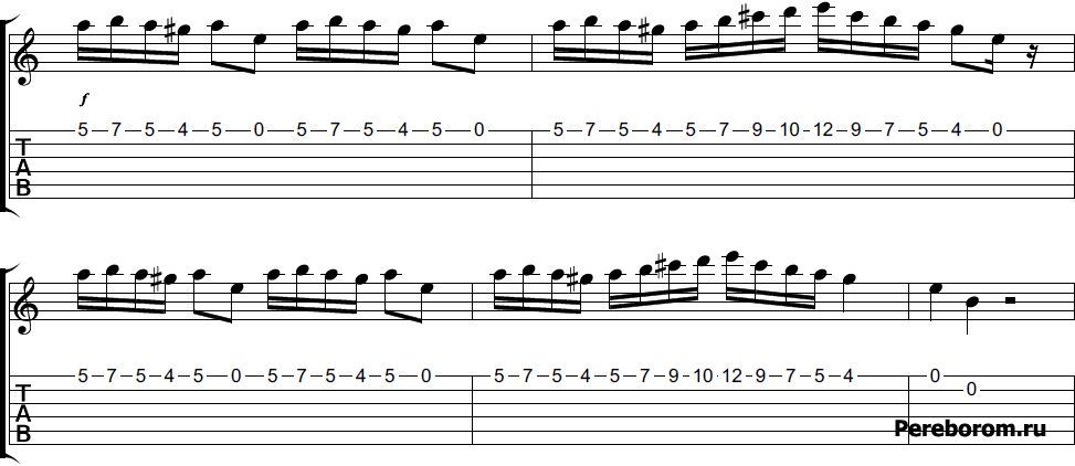
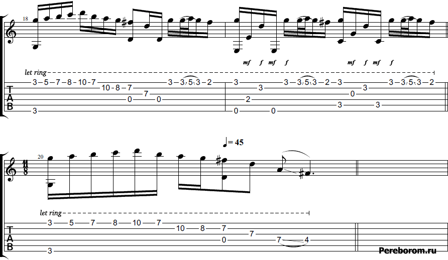
«River flows in you» на одной струне

Специально для начинающих и желающих разучить простой мотив, мы подобрали «River flows in you» на гитаре на одной струне. Учиться, и запоминается такая мелодия очень легко, т.к. все извлекаемые ноты на грифе находятся рядом друг с другом. Для удобства используйте все 4 пальца левой руки, так вы сможете плавно и без запинок зажимать нужные лады. В обратном случае, если зажимать струны только указательным пальцем, у вас вряд ли получится исполнить мелодию ровно и чисто. Чтобы разнообразить и немного обогатить звучание, попробуйте использовать прием «Слайд».
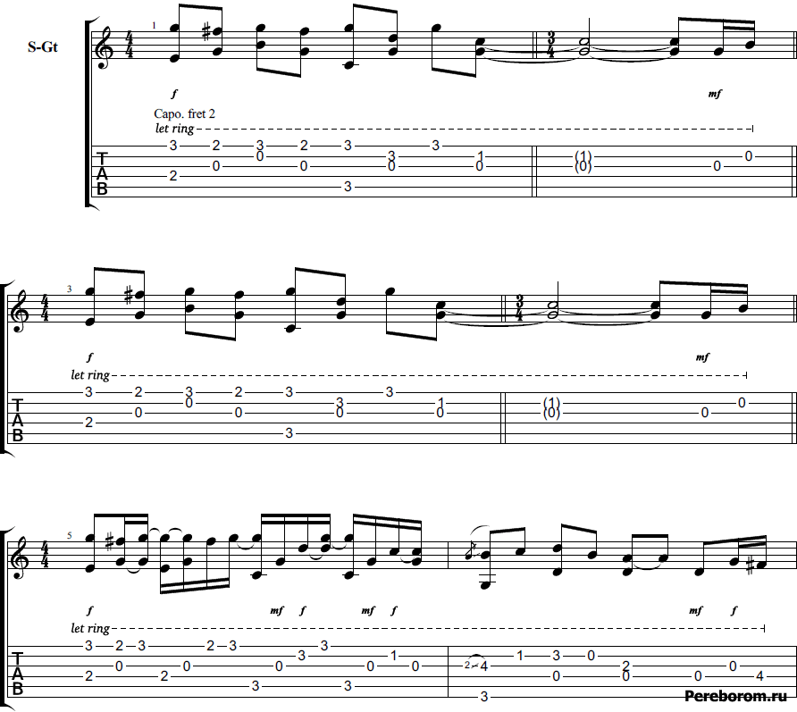
«River flows in you» — разбор сложного варианта


Как мы уже писали выше, для игры табулатур сложного варианта потребуется установить каподастр на втором ладу. Перед игрой обязательно проверьте настройку инструмента, это нужно для того чтобы мелодия звучала ровно на 1 тон выше, если ваша гитара не будет строить, то вы сразу заметите разнобой в звучании нот.

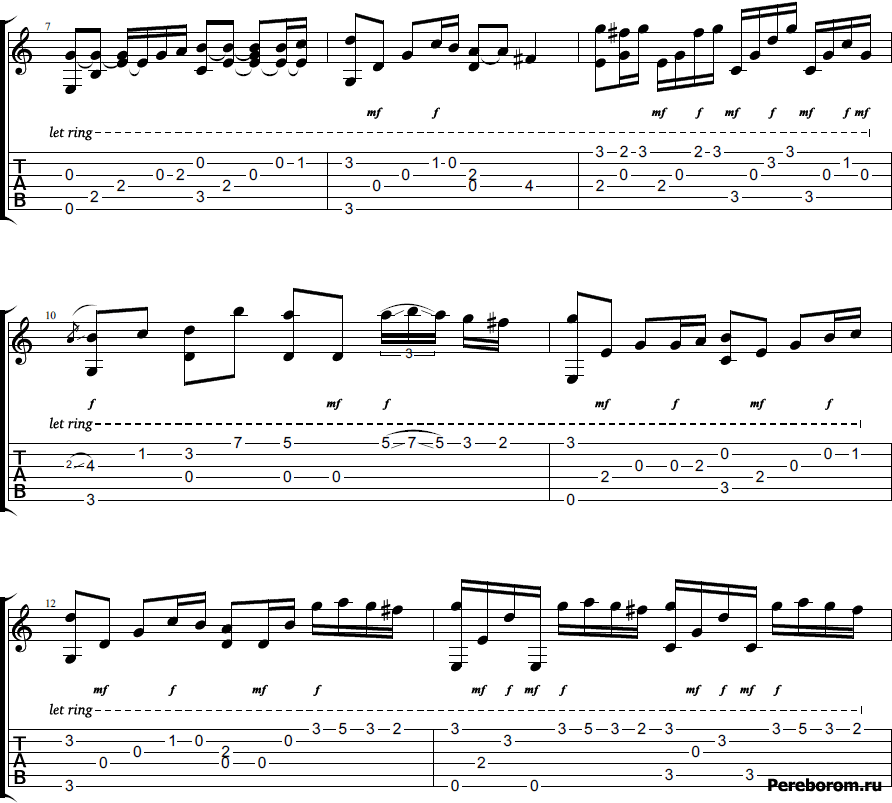
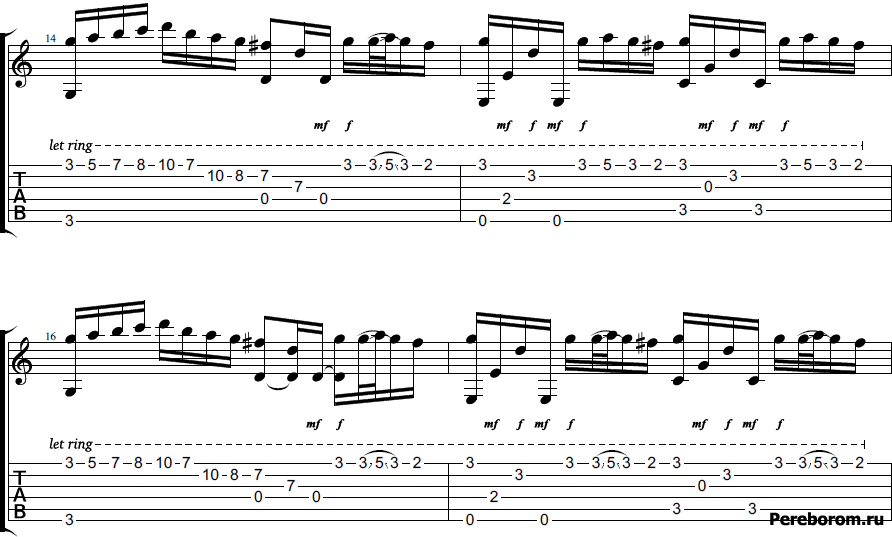
Разбейте композицию на фрагменты, это поможет быстрее запомнить табулатуры и отточить вашу игру. С 1 по 12 такт идет первая часть, в ней много технических моментов, на которые стоит обратить внимание. А именно на длительность нот и выдерживание пауз. Вторая часть, с 13 по 20 такт включает в себя в основном шестнадцатые ноты и более оживленное звукоизвлечение. Тут стоит сбавить обороты и потренироваться в медленном темпе, чтобы добиться чистого звучания.

В процессе занятий отработайте постановку позиций на грифе и перестановку пальцев, так как «River flows in you» на гитаре очень непростая и многие фрагменты требуют отдельного внимания. Чтобы не путаться, лучше за ранее разучить все основные позиции пальцев левой руки, и отработать их смену. По сути это ничем не отличается от перестановки стандартных аккордов, только здесь вы отталкивайтесь от табулатур. Также обратите внимание на приемы легато, которые заметно украшают звучание.
«River flows in you» табы GTP

«River flows in you» табы для гитары, которые представлены ниже, можно скачать и запустить в программе Guitar Pro. Здесь есть разные аранжировки, которые помогут вам лучше во всем разобраться или выбрать тот вариант, который по душе.
- Табулатура без капо #1 — Скачать (11 Kb)
- Табулатура без капо #2 — Скачать (6 Kb)
- Табулатура рок версия — Скачать (21 Kb)
- Табулатура (с правками от Pereborom.ru) — Скачать (29 Kb)
-
Contents
-
Table of Contents
-
Troubleshooting
-
Bookmarks
Quick Links
Instruction manual
General instructions digital
Mass Flow / Pressure instruments
laboratory style / IN-FLOW
Doc. no.: 9.17.022V Date: 12-01-2016
ATTENTION
Please read this instruction manual carefully before installing and operating the instrument.
Not following the guidelines could result in personal injury and/or damage to the equipment.
Summary of Contents for BRONKHORST IN-FLOW
-
Page 1
Instruction manual General instructions digital Mass Flow / Pressure instruments laboratory style / IN-FLOW Doc. no.: 9.17.022V Date: 12-01-2016 ATTENTION Please read this instruction manual carefully before installing and operating the instrument. Not following the guidelines could result in personal injury and/or damage to the equipment. -
Page 2
More information can be found in other documents. Multibus instruments have modular instruction manuals consisting of: General instructions digital Mass Flow / Pressure instruments laboratory style / IN-FLOW (document nr. 9.17.022) Operation instructions digital instruments (document nr. 9.17.023) Fieldbus/interface description: FLOW-BUS interface (document nr. -
Page 3
However, if the product has been returned collect to Bronkhorst High-Tech B.V., these costs are added to the repair invoice. Import and/or export charges, foreign shipping methods/carriers are paid for… -
Page 4
® BRONKHORST Short-Form Operation Instruction Before installing your Mass Flow or Pressure Meter/Controller it is important to read the attached label and check: — flow/pressure rate — fluid to be metered — up- and downstream pressures — input/output signal Check the red-coloured sticker and make sure the testpressure is in agreement with normal safety factors for your application. -
Page 5
® BRONKHORST BUS/digital operation For this procedure: See description for specific fieldbus Send a setpoint to the instrument and check the measured value Let the instrument warm-up for 30 minutes for best accuracy Your Mass Flow/Pressure Meter/Controller is now ready for operation. -
Page 6
® BRONKHORST… -
Page 7: Table Of Contents
® BRONKHORST TABLE OF CONTENTS Introduction …………………………9 General description……………………..9 1.1.1 Gas flow ……………………….9 1.1.2 Liquid flow ……………………….9 1.1.3 Pressure ……………………….9 1.1.4 Housings ……………………….9 …
-
Page 8
® BRONKHORST Liquid flow sensor ……………………..28 Pressure sensor ……………………… 28 Controllers ……………………….28 Control valves ……………………….28 4.6.1 Solenoid valves ……………………..29 4.6.2 Vary-P valve ……………………..29 … -
Page 9: Introduction
1.1 General description 1.1.1 Gas flow ® The Bronkhorst series mass flow meter for gases is an accurate device for measuring gas flows up to 700 bar depending on body rating, virtually independent of pressure and temperature changes. The system can be completed with a control valve and flexible readout to measure and control gas flows…
-
Page 10
® BRONKHORST IN-FLOW , IN-PRESS To comply with the IP65 ingress protection standard, the p.c. board is housed in a sealed casted metal housing. For electrical connections the instrument has a 8DIN male connector for analog/RS232 operation and for digital operation various connectors on top. -
Page 11: Valves
® BRONKHORST 1.1.5 Valves Laboratory style For gases: The solenoids of these valves have an IP50 ingress protection class. This means that the valves are suited for dry (indoor) use. For liquids: The solenoids of these valves have an IP50 ingress protection class.
-
Page 12: Sensor Principles
1.2.2 Gas flow sensors (direct mass flow measurement, CTA based) The IN-FLOW CTA models operate on the principle of direct thermal mass flow measurement. The thru-flow design sensor consists of a heater resistor and a temperature sensing resistor. Both resistors are made of temperature sensitive resistive material that is covered with a stainless steel tube.
-
Page 13: The Cta Based Liqui-Flow Model For Flow Rates Up To Approximately 1000 G/H
® BRONKHORST 2) The CTA based LIQUI-FLOW model for flow rates up to approximately 1000 g/h. The CTA based LIQUI-FLOW model basically consists of a small capillary tube with two sensing elements placed around it. The upstream sensing element is a temperature sensor that is used to measure the temperature of the liquid flowing through the tube.
-
Page 14: Pilot Operated Valve
® BRONKHORST 1.3.3 Pilot operated valve For high flow rates the pilot operated valve has been designed. A solenoid driven control valve controls the pressure difference across a piston, which lifts the main plunger. pilot valve pressur compensating valve flowcontrol valve 1.3.4 Bellows valve…
-
Page 15: For Liquids
® BRONKHORST 1.4.2 For liquids This calculation method can be used to determine the K -value of the main orifice of a control valve. 1000 Units: = volume flow [m = density at 20°C and 1 atm [kg/m p = delta p [bard]…
-
Page 16: Maximum Pressure Drop
® BRONKHORST 1.4.3 Maximum pressure drop For (pilot) solenoid operated control valves with small orifices the maximum allowable pressure drop for gases is according to the table. Diameter [mm] Normally closed Normally opened p max. [bard] p max. [bard] 0,05…
-
Page 17: Conversion Factors
® BRONKHORST 1.6 Conversion factors 1.6.1 Gas conversion factors (by-pass measurement) The general formula for determining the relationship between signal and mass flow is: signal in which: = output signal…
-
Page 18: Gas Conversion Factors (Direct Mass Flow Measurement, Cta-Based)
® BRONKHORST The approximate accuracy of the conversion factors listed is: typical for conversion factors; > 1 2% x factor < 1 2% / factor However, as the accuracy of the factor also depends on viscosity, pressure and temperature, special attention should be taken for gases in the gas/liquid state where specific heat, density and viscosity can vary tremendously.
-
Page 19: Liquid Conversion Factors
® BRONKHORST ® most common gases, which is accurate at both lower and higher flow ranges. Consult Bronkhorst applications. At nominal flow ranges for each instrument, a good approximation is the use of the so-called “CFDirect” conversion method, which comes with the FLUIDAT software.
-
Page 20: Installation
If the instruments have been used with toxic or dangerous fluids the customer should pre-clean the instrument. Important: Clearly note, on top of the package, the customer clearance number of Bronkhorst High-Tech B.V., namely: NL801989978B01 If applicable, otherwise contact your distributor for local arrangements.
-
Page 21: Mounting
® BRONKHORST 2.4 Mounting The mounting position depends on the type of instrument. For flowmeters the preferred position is horizontal, and at high pressures all meters should be mounted in this position. Avoid installation in close proximity of mechanic vibration and/or heat sources.
-
Page 22: Piping
® BRONKHORST 2.7 Piping BE SURE THAT PIPING IS ABSOLUTELY CLEAN! DO NOT install small diameter piping on high flowrates, because the inlet jetflow will affect the accuracy. DO NOT mount abrupt angles direct on in- and outlet, especially not on high flowrates. We recommend at least 10 pipe diameters distance between the angle and the instrument.
-
Page 23: Supply Pressure
However compliance with the EMC requirements is not possible without the use of proper cables and connector/gland assemblies. ® For good results Bronkhorst can provide standard cables. Otherwise follow the guidelines as stated below. Fold the shield of the cable back over the cable (the shield must be around the cable).
-
Page 24
® BRONKHORST 8DIN connector assembly Notes: 1. When connecting the system to other devices (e.g. to PLC), be sure that the integrity of the shielding is not affected. Do not use unshielded wire terminals. 2. For FLOW-BUS S(F)TP data (patch) cable connection to RJ45 connectors follow the instructions of the supplier. -
Page 25: Operation
BRONKHORST OPERATION 3.1 General ® The Bronkhorst instruments are designed in such a way that they will meet user process requirements in the best possible way. Basically all digital meters/controllers are powered with +15 Vdc to +24 Vdc. When providing your own power supply be sure that voltage and current rating are according to the specifications of the instrument(s) and furthermore that the source is capable of delivering enough energy to the instrument(s).
-
Page 26: Start-Up
® BRONKHORST See the appropriate documentation for more detailed information. 3.4 Start-up Turn on fluid supply gently. Avoid pressure shocks, and bring the instrument gradually up to the level of the actual operating conditions. Also switch off fluid supply gently. In case of liquid control be sure to remove all trapped gas bubbles from the system.
-
Page 27: Analog Operation
The instruments are compatible in use with analog instruments on this point. Analog operated instruments can be hooked-up using an 8-wire shielded cable with 9-pin D-connectors or ® 8DIN connectors, connected according to the Bronkhorst standard. Each electronic p.c.board is set for one of the following output (and corresponding input) signals:…
-
Page 28: Maintenance
® BRONKHORST — adjustable response time for stable control (|setpoint-measure| < 2%) Note: Special RS232 cable consists of a T-part with 1 male and 1 female sub-D 9 connector / 8DIN connector on one instrument-side and a normal female sub-D 9 connector on the side of the computer. See hook-up diagram for the correct RS232 cable which should be used.
-
Page 29: Solenoid Valves
® BRONKHORST 4.6.1 Solenoid valves These are considered to be the direct operated control and pilot valves. They may be disassembled in the field by the user for cleaning and servicing. The parts can be cleaned with a cleaning liquid, or in an ultrasonic bath.
-
Page 30: Digital Instrument
® BRONKHORST Digital instrument See document number 9.17.023 for detailed description. This document is available as PDF on the Multibus documentation/software tool CD. Interface description For a description of the available interfaces see document numbers: 9.17.024 for FLOW-BUS 9.17.025 for PROFIBUS-DP 9.17.026 for DeviceNet…
-
Page 31: Troubleshooting Summary General
® BRONKHORST 7.2 Troubleshooting summary general Symptom Possible cause Action No output signal No power supply 1a) check power supply 1b) check cable connection Output stage blown-up due to long 1c) return to factory lasting shortage and/or high-voltage peaks Supply pressure too high, or differential…
-
Page 32
APPENDIX 1 GAS CONVERSION TABLE Doc. no.: 9.02.071… -
Page 34
GAS CONVERSION FACTOR Nr.: Name: Symbol Density Heat capacity* Conversion factor ρ [ / ] − cal cal g K / . ] 20°C, 1 atm. 0°C, 1 atm. 20°C, 1 atm. Acetylene (Ethyne) 1.172 0.438 0.61 1.293 0.241 1.00 Allene (Propadiene) 1.832 0.392… -
Page 35
GAS CONVERSION FACTOR Nr.: Name: Symbol Density Heat capacity* Conversion factor ρ [ / ] − cal cal g K / . ] 20°C, 1atm. 20°C, 1atm. 0°C, 1 atm. Helium 0.1785 1.24 1.41 Helium (3-) 0.1346 1.606 1.44 Hydrogen 0.08991 3.44 1.01… -
Page 36
APPENDIX 2 dimensions digital cases… -
Page 38
Dimensions digital cases Doc. Nr.: 7.05.445H Date: 21-07-2015 One of these digital case assemblies replaces the case assembly as drawn in the dimensional drawing. Please note that the height increases when a contra connector is used. analog / RS232 FLOW-BUS / Modbus DeviceNet PROFIBUS EtherCAT/PROFINET…
-
0 ₽ 0 товаров
Каталог инструкций по эксплуатации на русском языке
В нашем каталоге более 90.000 инструкций по эксплуатации и руководств пользователя на русском языке к бытовой технике и электронике. Чтобы скачать инструкцию по эксплуатации выберите интересую вас категорию или воспользуйтесь поиском в верхнем правом углу сайта.