-
Contents
-
Table of Contents
-
Bookmarks
Quick Links
Agilent 7890A
Gas Chromatograph
Operating Guide
Agilent Technologies
Related Manuals for Agilent Technologies 7890A
Summary of Contents for Agilent Technologies 7890A
-
Page 1
Agilent 7890A Gas Chromatograph Operating Guide Agilent Technologies… -
Page 2
Notices © Agilent Technologies, Inc. 2007-2010 Warranty Safety Notices No part of this manual may be reproduced The material contained in this docu- in any form or by any means (including ment is provided “as is,” and is sub- C A U T I O N… -
Page 3: Table Of Contents
Contents Introduction Where to Find Information Online User Documentation Chromatography Using a GC The Front View of the Agilent 7890A GC The Back View of the Agilent 7890A GC The Inlets The GC Column and Oven Capillary Flow Technology Detectors…
-
Page 4
To start running a sequence To pause a running sequence To resume a paused sequence To stop a running sequence To resume a stopped sequence Aborting a sequence To resume an aborted sequence Keypad Operation The Run Keys The Service Mode Key The GC Component Keys The Status Key The Info Key… -
Page 5
To Move the 7693A ALS to the Other GC Inlet Check your work Impact on your data system To Adapt the 7693A ALS for the COC Inlet Operating the 7683 Automatic Sampler 7683 ALS Turret Types To Change the 7683 ALS Turret To Move the 7683 ALS to the Other GC Inlet To Park the Injector To Install a Syringe on the 7683 ALS… -
Page 6
Operating Guide… -
Page 7: Introduction
Agilent 7890A Gas Chromatograph Operating Guide Introduction Where to Find Information Chromatography Using a GC The Front View of the Agilent 7890A GC The Back View of the Agilent 7890A GC The Inlets The GC Column and Oven Capillary Flow Technology…
-
Page 8: Where To Find Information
In addition to this document, Agilent provides several learning products that document how to install, operate, maintain, and troubleshoot the Agilent 7890A GC. Before operating your GC, be sure to read the safety and regulatory information included on the Agilent GC and GC/MS Hardware User Information &…
-
Page 9
Introduction • Operating guides • Maintenance information • Troubleshooting details Operating Guide… -
Page 10: Chromatography Using A Gc
Detecting what compounds were in the sample. (This is done in the detector.) During this process, status messages from the Agilent 7890A GC are displayed, and user changes to parameter settings can be made through the operating panel.
-
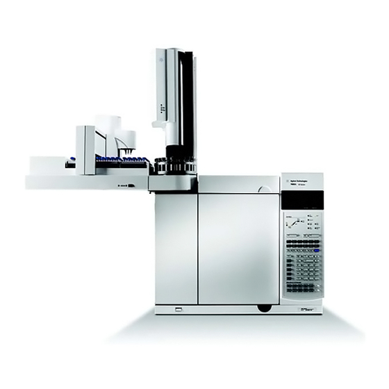
Page 11: The Front View Of The Agilent 7890A Gc
Introduction The Front View of the Agilent 7890A GC Detector cover Detectors Inlets Valves (not shown) Display Keypad Power switch Oven Latch The Back View of the Agilent 7890A GC Oven exhaust vent Inlet and detector vent Gas supply connections…
-
Page 12: The Inlets
Introduction The Inlets Inlets are where samples are injected into the GC. The Agilent 7890A GC can have a maximum of two inlets, identified as Front Inlet and Back Inlet. A complete selection of inlets—split/splitless [0–100 psi and 0–150 psi], multimode, purged packed, cool- on- column, programmed temperature vaporization, and volatiles interface—are available.
-
Page 13
Valves are most frequently used to sample gases or liquids in constantly flowing streams. The Agilent 7890A GC can accommodate up to two gas sampling valves, identified as Valve # 1 and Valve #2. Operating Guide… -
Page 14
Introduction The valves are located inside the gas sampling valve box. Gas Sampling Valve box Operating Guide… -
Page 15: The Gc Column And Oven
Introduction The GC Column and Oven GC columns are located inside a temperature- controlled oven. Generally, one end of the column is attached to the inlet, while the other end is attached to the detector. Columns vary in length, diameter, and internal coating. Each column is designed for use with different compounds.
-
Page 16: Capillary Flow Technology
Introduction Capillary Flow Technology Agilent capillary flow technology (CFT) devices are used for splitting, heart cutting, and reliable zero dead volume connections. The features of the capillary flow technology make traditionally difficult connections simple, reliable, and leak free. The optional CFT switches, splitters, and QuickSwap accessories are located on the inside of the oven wall.
-
Page 17: Detectors
Agilent ChemStation—where it shows up as a peak on a chromatogram. The Agilent 7890A GC can accommodate up to three detectors, identified as Front Det, Back Det, and Aux Det. A complete selection of detectors (FID, TCD, NPD, FPD, µECD, MSD, Triple Quadrupole MS, and ICP- MS) is available.
-
Page 18: The Operating Panel
The display The display shows details of what is currently happening in the Agilent 7890A GC and allows you to make changes to parameters as necessary. Use the scroll keys to view additional lines in the display.
-
Page 19: Status Lights
Introduction Status lights The status lights provide a basic look at what is currently happening inside the Agilent 7890A GC. A lit LED on the status board indicates: • The current progress of a run (Pre Run, Post Run, and Run).
-
Page 20: Blinking Setpoint
Introduction Fault messages indicate hardware problems that require user intervention. Depending on the type of error, the GC will beep once or not at all. Blinking setpoint If a gas flow, multiposition valve, or the oven is shut down by the system, Off or On/Off will blink on the appropriate line of the components parameter listing.
-
Page 21: The Keypad
Introduction The keypad All of the parameters required to operate the Agilent 7890A GC can be entered through the GC’s keypad. Normally, however, most of these parameters are controlled using an attached data system, such as the Agilent ChemStation. When the Agilent ChemStation is controlling your Agilent 7890A GC, it is possible for the ChemStation to disable editing of the GC’s current method from the keypad.
-
Page 22
Introduction Operating Guide… -
Page 23
To Start Up the GC To Shut Down the GC for Less Than a Week To Shut Down the GC for More Than a Week This section describes the tasks that an operator performs when using the Agilent 7890A GC. Agilent Technologies… -
Page 24: Operating Basics
Operating Basics Overview Operating the GC involves the following tasks: • Setting up the GC hardware for an analytical method. • Starting up the GC. See “To Start Up the GC”. • Preparing the automatic liquid sampler. Install the method- defined syringe; configure solvent and waste bottle usage and syringe size;…
-
Page 25: Instrument Control
Operating Basics Instrument Control The Agilent 7890A GC is typically controlled by an attached data system such as Agilent ChemStation. Alternately, the GC can be controlled entirely from its keypad, with output data being sent to an attached integrator for report generation.
-
Page 26: Correcting Problems
Operating Basics Correcting Problems If the GC stops operation because of a fault, for example a flow module shutdown after running out of carrier gas, do the following: Use the keyboard or data system to stop the alert tone. Click [Clear] on the keyboard or turn off the offending component in the data system.
-
Page 27: To Start Up The Gc
Operating Basics To Start Up the GC Successful operation begins with a properly installed and maintained GC. The utility requirements for gases, power supply, venting of hazardous chemicals, and required operational clearances around the GC are detailed in the Site Preparation Checklist.
-
Page 28: To Shut Down The Gc For Less Than A Week
Operating Basics To Shut Down the GC for Less Than a Week Wait for the current run to finish. If the active method has been modified, save the changes. Never leave flammable gas flows on if the GC will be unmonitored. WA R N I N G If a leak develops, the gas could create a fire or explosion hazard.
-
Page 29: To Shut Down The Gc For More Than A Week
Operating Basics To Shut Down the GC for More Than a Week Load a GC maintenance method and wait for the GC to become ready. For more information about creating maintenance methods, see the Maintaining Your GC manual. (If a maintenance method is not available, set all heated zones to 40 °C.) Turn off the main power switch.
-
Page 30
Operating Basics Operating Guide… -
Page 31: Running A Method Or A Sequence From The Keypad
Agilent 7890A Gas Chromatograph Operating Guide Running a Method or a Sequence from the Keypad Loading, Storing, and Running Methods from the Keypad Loading, Storing, and Running Sequences from the Keypad This section explains how to load, store, and run a method or sequence using the GC keypad, without the use of an Agilent data system.
-
Page 32: Loading, Storing, And Running Methods From The Keypad
Running a Method or a Sequence from the Keypad Loading, Storing, and Running Methods from the Keypad To load a method Press [Load]. Press [Method]. Enter the number of the method to be loaded (1 through Press [On/Yes] to load the method and replace the active method.
-
Page 33: To Abort A Method
Running a Method or a Sequence from the Keypad After the sample is loaded into the syringe, the sample is automatically injected when the GC reaches the ready state. To abort a method Press [Stop]. When you are ready to resume running analyses, load the appropriate sequence or method.
-
Page 34: Loading, Storing, And Running Sequences From The Keypad
Running a Method or a Sequence from the Keypad Loading, Storing, and Running Sequences from the Keypad A sequence can specify up to five subsequences to be run, as well as priority (ALS only) and post- run sequences, if defined. Each sequence is stored as a number (from 1 to 9). To load a sequence Press [Load][Seq].
-
Page 35: To Pause A Running Sequence
Running a Method or a Sequence from the Keypad The Run LED will light and stay lit until the sequence is completed. The sequence continues to run until all subsequences are executed or until the sequence is aborted. To pause a running sequence Press [Seq Control].
-
Page 36: To Resume An Aborted Sequence
Running a Method or a Sequence from the Keypad • A running sequence tries to load a method that doesn’t exist. • The sampler is turned off. To resume an aborted sequence Correct the problem. (See «Aborting a sequence».) Press [Seq Control]. Scroll to Resume sequence and press [Enter].
-
Page 37: Keypad Operation
Keypad Functionality When the GC Is Controlled by an Agilent Data System About GC Status About Logs This section describes the basic operation of the Agilent 7890A GC keypad. For additional information on keypad functionality, see the Advanced User Guide. Agilent Technologies…
-
Page 38: The Run Keys
Keypad Operation The Run Keys These keys are used to start, stop, and prepare the GC to run a sample. [Prep Run] Activates processes required to bring the GC to the starting condition dictated by the method (such as turning off the inlet purge flow for a splitless injection or restoring normal flow from gas saver mode).
-
Page 39: The Gc Component Keys
Keypad Operation The GC Component Keys These keys are used to set the temperature, pressure, flow, velocity, and other method operating parameters. To display the current settings, press any one of these keys. More than three lines of information may be available. Use the scroll keys to view additional lines, if necessary.
-
Page 40: The Status Key
Keypad Operation The Status Key [Status] Toggles between setpoint/actual values for most commonly reviewed parameters and displays “ready,” “not ready,” and “fault” information. When the Not Ready status light is blinking, a fault has occurred. Press [Status] to see which parameters are not ready and what fault has occurred.
-
Page 41: The Info Key
Keypad Operation The Info Key [Info] Provides help for the currently shown parameter. For example, if Oven Temp is the active line in the display (has a < next to it), [Info] will display the valid range of oven temperatures. In other cases, [Info] will display definitions or actions that need to be performed.
-
Page 42: The General Data Entry Keys
Keypad Operation The General Data Entry Keys [Mode/Type] Accesses a list of possible parameters associated with a component’s nonnumeric settings. For example, if the GC is configured with a split/splitless inlet and the [Mode/Type] key is pressed, the options listed will be split, splitless, pulsed split, or pulsed splitless.
-
Page 43: The Supporting Keys
Keypad Operation The Supporting Keys [Time] Displays the current date and time on the first line. The two middle lines show the time between runs, the elapsed time and time remaining during a run, and the last run time and post- time during a post- run.
-
Page 44: Method Storage And Automation Keys
Keypad Operation Method Storage and Automation Keys These keys are for loading and storing methods and sequences locally on your GC. They cannot be used to access methods and sequences stored by your Agilent ChemStation. [Load] Are used to load and store methods and [Method] sequences on your GC.
-
Page 45: Keypad Functionality When The Gc Is Controlled By An Agilent Data System
Keypad Operation Keypad Functionality When the GC Is Controlled by an Agilent Data System When an Agilent data system controls the GC, the data system defines the setpoints and runs the samples. If configured to lock the keypad, the data system can prevent the changing of setpoints.
-
Page 46: About Gc Status
Keypad Operation About GC Status When the GC is ready to begin a run, the display screen shows STATUS Ready for Injection. Alternatively, when a component of the GC is not ready to begin a run, the Not Ready LED is lit on the status board. Press [Status] to see a message explaining why the GC is not ready.
-
Page 47: Error Conditions
Keypad Operation A continuous tone sounds if a hydrogen flow is shut down or a thermal shutdown occurs. Before resuming GC operations, investigate and resolve the cause WA R N I N G of the hydrogen shutdown. See Hydrogen Shutdown in the Troubleshooting manual for details.
-
Page 48: About Logs
Keypad Operation About Logs Three logs are accessible from the keypad: the run log, the maintenance log, and the system event log. To access the logs, press [Logs] to toggle to the desired log. The display will indicate the number of entries the log contains. Scroll through the list.
-
Page 49: Operating The 7693A Automatic Sampler
Agilent 7890A Gas Chromatograph Operating Guide Operating the 7693A Automatic Sampler Placing Vials in the 7693A ALS To Park the Injector To Install a Syringe on the 7693A ALS To Remove the Syringe on the 7693A ALS To Configure Solvent/Waste Vials…
-
Page 50: Placing Vials In The 7693A Als
Operating the 7693A Automatic Sampler Placing Vials in the 7693A ALS Two turrets are provided with the G4513A injector (Figure 1). The 16- sample standalone turret, and the 3- sample transfer turret. B3 B4 11 10 Standalone turret Transfer turret (16 samples) (3 samples) Top views.
-
Page 51: Placing Vials In The Sample Tray
Operating the 7693A Automatic Sampler Table 2 Transfer turret labels Position Label Bottle/Vial Dedicated vial transfer position A Layer 1 bottle Configurable vial transfer position Layer 2 bottle Configurable vial transfer position Layer 3 bottle 4 and 5 Waste B1 — B2 bottles 6 through 8 Waste A1 — A3 bottles 9 through 12…
-
Page 52: Placing Vials In The Turret (No Sample Tray)
Operating the 7693A Automatic Sampler Place up to 150 samples in the three vial racks, according to the programmed sequence. Figure 2 shows tray loading for a sequence that uses tray positions 6 through 21. First vial in position 6 Last vial in position 21 Figure 2…
-
Page 53
Operating the 7693A Automatic Sampler Air gap 1 Air gap 2 Layer 1 (L1) Layer 2 (L2) Figure 3 2-layer sandwich injection Air gap 1 Air gap 2 Air gap 3 Layer 1 (L1) Layer 2 (L2) Layer 3 (L3) Figure 4 3-layer sandwich injection When loading vials for sandwich injections, layer 1 (L1) can… -
Page 54: To Park The Injector
Operating the 7693A Automatic Sampler To Park the Injector To park an injector (safely set it aside so it is not used), simply place it on an installed parking post (G4513- 20562). Operating Guide…
-
Page 55: To Install A Syringe On The 7693A Als
Operating the 7693A Automatic Sampler To Install a Syringe on the 7693A ALS To install a syringe (Figure Plunger carrier Slide Plunger screw Plunger Syringe carrier Flange Flange guide Barrel Syringe latch Needle Needle support foot Figure 6 Installing a syringe Unplug the injector cable, and if desired, mount the injector on a parking post, or lay the injector tower on a work bench.
-
Page 56
Operating the 7693A Automatic Sampler Slide the plunger carrier down until it is completely over the syringe plunger, and tighten the plunger thumb screw until finger- tight. Manually move the plunger carrier up and down. If the syringe plunger does not move along with the carrier, repeat the previous steps until installed correctly. -
Page 57
Operating the 7693A Automatic Sampler Close the injector door. Do the following only if the injector tower was removed from the mounting post during installation: If necessary, plug in the injector cable. Install the injector on the mounting post. If you have a sample tray, calibrate the ALS system. Operating Guide… -
Page 58: To Remove The Syringe On The 7693A Als
Operating the 7693A Automatic Sampler To Remove the Syringe on the 7693A ALS To remove a syringe: Unplug the injector cable, and if desired, mount the injector on a parking post. Open the injector door. Slide the syringe carriage to the top position. Completely loosen the plunger thumb screw until it reaches the stop, and lift the plunger carrier off of the syringe plunger.
-
Page 59: To Configure Solvent/Waste Vials
Operating the 7693A Automatic Sampler To Configure Solvent/Waste Vials Press [Config] [Front Injector] or [Config] [Back Injector] on the GC keypad to display the front or back injector configuration parameters. CONFIGURE FRONT INJECTOR Wash Mode Bottles 1 A, 1 B Syringe Size 10.0 Wash Mode Bottles —…
-
Page 60: 7693A Als Prerun Checklist
Operating the 7693A Automatic Sampler 7693A ALS Prerun Checklist Use this checklist before running analyses to make sure that the sample vials and sampler are ready. Sample vials are at least half full. Vial cap is centered, with no wrinkles, and the septum is flat.
-
Page 61: To Move The 7693A Als To The Other Gc Inlet
Operating the 7693A Automatic Sampler To Move the 7693A ALS to the Other GC Inlet When no runs are scheduled, lift the injector tower off the mounting post. If a tray is installed, disconnect the communications cable from the injector tower. Set the injector tower aside.
-
Page 62: Check Your Work
Operating the 7693A Automatic Sampler If the injector cable is disconnected, reconnect it to the injector cable port. Injector cable port Position the injector on the desired mounting post and inlet cover support foot. Check your work The injector must be vertical and stable. If the injector will not sit upright on the GC, check that the plumbing and cabling under the inlet cover are properly routed in their channels.
-
Page 63: To Adapt The 7693A Als For The Coc Inlet
Operating the 7693A Automatic Sampler To Adapt the 7693A ALS for the COC Inlet μ The 7693A injectors can inject samples directly into 250- μ μ 320- m, and 530- m columns in GCs with a cool- on- column inlet. When performing cool on- column injections, the injector: •…
-
Page 64
Operating the 7693A Automatic Sampler Operating Guide… -
Page 65: Operating The 7683 Automatic Sampler
Agilent 7890A Gas Chromatograph Operating Guide Operating the 7683 Automatic Sampler 7683 ALS Turret Types To Change the 7683 ALS Turret To Move the 7683 ALS to the Other GC Inlet To Park the Injector To Install a Syringe on the 7683 ALS…
-
Page 66: 7683 Als Turret Types
Operating the 7683 Automatic Sampler 7683 ALS Turret Types The injector comes with two turrets, a standard 1- sample transfer turret for use with or without a tray, and an 8- sample turret to be used without a tray. Hi-density turret Transfer turret (8-samples) (1-sample)
-
Page 67: To Change The 7683 Als Turret
Operating the 7683 Automatic Sampler To Change the 7683 ALS Turret If the GC does not have a tray, proceed to step Otherwise, do the following: • If changing from the 1- sample transfer turret to the 8- sample turret, press [Sample Tray] [Off/No]. •…
-
Page 68
Operating the 7683 Automatic Sampler Close the injector door. The injector will verify the turret type if the injector is on. If the Fault light comes on, the turret is not installed correctly. Operating Guide… -
Page 69: To Move The 7683 Als To The Other Gc Inlet
Operating the 7683 Automatic Sampler To Move the 7683 ALS to the Other GC Inlet When no runs are scheduled, unplug the injector from the back of the GC. Lift the injector tower off the mounting post and set it aside.
-
Page 70
Operating the 7683 Automatic Sampler Alignment pin Hole Mounting post Alignment hole Inlet cover Turn the injector so that the turret faces either: • The front of the GC (for front location) • The left side of the GC (for back location) Lower the injector until the alignment pin in the base enters the alignment hole in the inlet cover. -
Page 71: To Park The Injector
• Former parking post = 05890- 20795 (not compatible with 7890A) • New parking post = G4513- 20562 (compatible with 7890A and previous GCs) To park the injector, simply place it on an installed post.
-
Page 72: To Install A Syringe On The 7683 Als
Operating the 7683 Automatic Sampler To Install a Syringe on the 7683 ALS Open the injector door. Remove the syringe, if necessary. (See “To Remove the Syringe on the 7683 ALS”.) Slide the syringe carriage up (or down). Pass the syringe needle through the hole in the needle support foot.
-
Page 73
Operating the 7683 Automatic Sampler Syringe latch (closed) Needle support Do not operate the injector without a syringe in place. The syringe C A U T I O N latch may interfere with the motor if the latch is allowed to swing freely. -
Page 74: To Remove The Syringe On The 7683 Als
Operating the 7683 Automatic Sampler To Remove the Syringe on the 7683 ALS Open the injector door. Loosen the plunger screw and raise the plunger carrier loop off the syringe plunger. Open the syringe latch. Plunger carrier loop Plunger screw Flange guide Syringe carrier Syringe latch (open)
-
Page 75: To Configure Solvent/Waste Vials
Operating the 7683 Automatic Sampler To Configure Solvent/Waste Vials Press [Config] [Front Injector] or [Config] [Back Injector] to display the parameters. Scroll to the desired parameter detailed below. CONFIGURE FRONT INJECTOR Front Tower INJ1< Wash Mode 2-A, 2-B Syringe size 10.0 )—Press [Mode/Type] to select Front Tower…
-
Page 76
Operating the 7683 Automatic Sampler The G2913A injector always uses both WA waste bottles if a solvent A wash is used and both WB waste bottles if a solvent B wash is used. —G2613A This is only displayed when the Waste bottle mode G2613A injector has a 3- vial turret installed. -
Page 77: To Load Vials In The 7683 Als Turret
Operating the 7683 Automatic Sampler To Load Vials in the 7683 ALS Turret Load waste and solvent bottles in the appropriate positions. Be sure that there is a waste bottle in each position of the turret, regardless of which ones are configured in the method.
-
Page 78: 7683 Als Prerun Checklist
Operating the 7683 Automatic Sampler 7683 ALS Prerun Checklist Use this checklist before running analyses to make sure that the sample vials and sampler are ready. Sample vials are at least half full. Vial cap is centered, with no wrinkles, and the septum is flat.
-
Page 79: To Adapt The 7683 Als For The Coc Inlet
Operating the 7683 Automatic Sampler To Adapt the 7683 ALS for the COC Inlet Select the on- column syringe needed for the column size. (See “Consumables and Parts for the COC Inlet”.) Check the needle- to- column size. (See To Check the Needle- to- Column Size with the COC Inlet.) Verify that the insert matches the needle size.
-
Page 80: To Install A 200-Μm Column With The Coc Inlet
Operating the 7683 Automatic Sampler To Install a 200-µm Column With the COC Inlet Agilent recommends using a 530-µm retention gap for injections N O T E directly onto 200-µm columns. Prepare the inlet. (See To Prepare for Inlet Maintenance.) Be careful! The oven and/or inlet may be hot enough to cause WA R N I N G burns.
-
Page 81
Agilent 7890A Gas Chromatograph Operating Guide About Methods, Sequences, and Data Analysis What Is a Method? What Is Saved in a Method? What Happens When You Load a Method? What Is a Sequence? Automating Data Analysis, Method Development, and Sequence… -
Page 82: About Methods, Sequences, And Data Analysis
About Methods, Sequences, and Data Analysis What Is a Method? A method is the group of settings required to accurately analyze a specific sample. Since every type of sample reacts differently in the GC—some samples require a higher oven temperature, others require a lower gas pressure or a different detector—a unique method must be created for each specific type of analysis.
-
Page 83: What Happens When You Load A Method
About Methods, Sequences, and Data Analysis What Happens When You Load a Method? There are two kinds of methods: • The active method—This is sometimes referred to as the current method. The settings defined in this method are the settings the GC is currently maintaining. •…
-
Page 84
About Methods, Sequences, and Data Analysis Operating Guide…
Предложите, как улучшить StudyLib
(Для жалоб на нарушения авторских прав, используйте
другую форму
)
Ваш е-мэйл
Заполните, если хотите получить ответ
Оцените наш проект
1
2
3
4
5
Главная » Agilent » Руководство пользователя МСД / газового хроматографа Agilent серии 5975
Руководство пользователя МСД / газового хроматографа Agilent серии 5975

View Fullscreen
Руководство пользователя МСД / газового хроматографа Agilent серии 5975 — Оптимизированный File
Руководство пользователя МСД / газового хроматографа Agilent серии 5975 — Оригинал File
Похожие сообщения
-

Руководство пользователя отсека для термостатированной колонки Agilent серии 1100
Руководство пользователя термостатированной колонки Agilent серии 1100 — оптимизированный PDF-файл Пользователь термостатированной колонки Agilent серии 1100…
-
Руководство пользователя коммерческих газовых водонагревателей серии AHRI 154
Руководство пользователя коммерческих газовых водонагревателей серии AHRI 154 — оптимизированный PDF-файл. Коммерческий газовый водонагреватель серии 154…
-
Руководство пользователя газовых водогрейных котлов GV90 + Series 2
Руководство пользователя газовых водогрейных котлов GV90 серии 2 — оптимизированный PDF-файл Газовые водогрейные котлы серии 90 GV2 Пользователь…
-
Техническое руководство по промышленным газовым обогревателям с прямым газовым обогревом серии S Cambridge S
Техническое руководство по промышленным газовым обогревателям с прямым газовым обогревом серии Cambridge — Оптимизированный PDF-файл Cambridge S-series Промышленные газовые обогреватели прямого действия.


Оставить комментарий
Ваш электронный адрес не будет опубликован. Обязательные поля помечены * *
КОММЕНТАРИЙ *
Имя и фамилия
Эл. адрес
Cайт
Сохраните мое имя, адрес электронной почты и веб-сайт в этом браузере для следующего комментария.

ИНСТРУКЦИЯ
ХРОМАТОГРАФЫ ЖИДКОСТНЫЕ Agilent 1100, Agilent 1200
Методика поверки
Москва 2006 г.
с_.
Настоящая инструкция распространяется на жидкостные хроматографы Agilent 1100, Agilent 1200 со спектрофотометрическим с измененяемой длиной волны, многоволновым спектрофотометрическим, на диодной матрице, рефрактометрическим и флуориметрическим детекторами и устанавливает и устанавливает методику их первичной и периодической поверок.
Межповерочный интервал 1 год.
1 ОПЕРАЦИИ ПОВЕРКИ
-
1.1 При проведении поверки должны выполняться операции, указанные в таблице 1.
Таблица 1
|
Наименование операции |
Номер пункта методических указаний |
Обязательное проведение операции |
|
|
при эксплуата ции |
После ремонта |
||
|
Внешний осмотр |
4.1. |
да |
да |
|
Опробование |
4.2. |
да |
да |
|
— определение уровня флуктуационных шумов нулевого сигнала |
4.2.1. |
да |
да |
|
— определение дрейфа нулевого сигнала |
4.2.2. |
да |
да |
|
— определение отношения сигнал/шум по Рамановскому спектру воды для флуоримет-рического детектора |
4.2.3. |
да |
да |
|
— определение предела детектирования |
4.2.4. |
да |
да |
|
Определение метрологических характеристик: |
4.3. |
да |
да |
|
— определение относительного среднего квадратического отклонения выходного сигнала |
4.3.1,- 4.3.4. |
да |
да |
|
— определение относительного изменения выходного сигнала за 8 часов непрерыв- |
ной работы ____________________4.3.5.- 4.3.6.____.________да__________, да ___
2 СРЕДСТВА ПОВЕРКИ, РЕАКТИВЫ И МАТЕРИАЛЫ
Контрольные вещества:
-ГСО 7895-2001 состава раствора кофеина в воде;
— аттестованные растворы антрацена в ацетонитриле.
Ацетонитрил для жидкостной хроматографии ТУ 6-09-14-2167-84. Вода дистиллированная по ГОСТ 6709-72. «Г
Колонка Hypersil ODS 125×4,0 мм.
Допускается применять другие средства поверки, метрологические характеристики которых соответствуют указанным в настоящей инструкции.
3. УСЛОВИЯ ПОВЕРКИ И ПОДГОТОВКА К НЕЙ
3.1 При проведении поверки соблюдают следующие условия:
|
20 ±5 84- 106.7 |
|
— относительная влажность воздуха, % |
30-90 |
|
— напряжение переменного тока, В |
220 ± 22 |
|
— частота сети, Гц |
50 ± 1 |
-
3.2 Подготовительные работы выполняют в соответствии с инструкцией по эксплуатации хроматографа.
При использовании системы Agilent ChemStation поверка хроматографа выполняется автоматически. Установку режимных параметров, проведение операций поверки и обработку результатов выполняют через функцию «Verification».
-
3.3 Перед проведением поверки готовят контрольные смеси, назначение и содержание анализируемых компонентов в которых приведено в таблице 2. Относительная погрешность аттестации не более 10%.

Таблица 2
Контрольный раствор
Массовая концентрация мг/дм3
Объем пробы, мкл
Элюент
Скорость потока элюента, см3/мин
—
Детектор
Кофеин—вода
0,125 /<?
5
Ацетонитрил : вода 4:1
и
Спектрофотометрический с измененяе-мой длиной волны
Многоволновой спектрофотометрический
На диодной матрице
Кофеин-вода
1,25
1
Ацетонитрил : вода
1
Рефрактометриче
ский

4 ПРОВЕДЕНИЕ ПОВЕРКИ
-
4.1 Внешний осмотр
При внешнем осмотре установливают:
-
— соответствие комплектности хроматографа паспортным данным:
-
— четкость маркировки;
-
— исправность механизмов и крепежных деталей.
-
4.2 Опробование
При опробовании проводят определение уровня флуктуационных шумов, дрейфа нулевого сигнала, отношения сигнал/шум по Рамановскому спектру воды для флуори-метрического детектора и предела детектирования для остальных детекторов.
-
4.2.1 Уровень флуктуационных шумов и дрейф нулевого сигнала определяют при условиях, указанных в таблице 3, после выхода хроматографа на режим (время выхода на режим для каждого детектора установлено в инструкции по эксплуатации). Уровень флуктуационных шумов и дрейф нулевого сигнала измеряют в динамическом режиме в течение 30 мин. В качестве элюента используют воду.
Уровень флуктуационных шумов нулевого сигнала (ДХ) принимают равным амплитуде (h) повторяющихся колебаний нулевого сигнала с периодом не более 20 секунд.
Таблица 3
|
Детектор |
||
|
Спектрофотометрический с измене-няемой длиной волны; многоволновой спектрофотометрический; на диодной матрице |
Рефрактометрический |
|
|
Элюент |
Вода |
Вода |
|
Скорость потока элюента, см’/мин |
0,8 |
1 |
|
Длина волны, нм |
254 |
— |
|
Постоянная |
2 |
4 |
времени, сек
-
4.2.2 При использовании системы Agilent ChemStation значения шума и дрейфа рассчитываются автоматически. Полученные значения не должны превышать значений, приведенных в таблице 4.
Таблица 4
|
Детектор |
Уровень флуктуа-цион-ных шумов нулевого сигнала (peak to peak) |
Дрейф нулевого сигнала |
|
Спектрофотометрический с изменяемой длиной волны — для 1100 7 — для 1200, 1200 SL |
4-10”5 е.о.п. 1,5-10”5 е.о.п. |
5-10-4 е.о.п./час 3-1 О’4 |
|
На диодной матрице, многоволновый спектрофотометрический
|
5,0-10”~ е.о.п. 2,0-10-5 е.о.п. 1,6-Ю-3 е.о.п. |
5,0-10^ е.о.п./час 2,0-10 J е.о.п./час 0,9-10~J е.о.п./час |
|
Рефрактометрический -для 1100 7 — для 1200 |
5,0-10-8 5,0-10-9 |
2-10_/ ед.рефр./час 2-10-7 ед.рефр./час |
-
4.2.3 Определение отношения сигнап/шум по Рамановскому спектру воды
Определения отношение сигнал/шум для флуориметрического детектора проводят согласно процедуре, описанной в Разделе 10 «Руководства по эксплуатации флуориметрического детектора» для хроматографа Agilent 1100 и Разделе 8 «Инструкции по сервисному обслуживанию» для хроматографа Agilent 1200 при длинах волн возбуждения 350 нм и эмиссии 392 нм.
Полученные значения должны быть не менее:
для Agilent 1100 series (вариант А платы FCF) 200:1
для остальных вариантов Agilent 1100 series 400:1
для Agilent 1200 series 500:1.
-
4.2.4 Определение предела детектирования
Предел детектирования определяют с использованием контрольных веществ и условий, указанных в таблице 2.
В хроматограф вводят пробу контрольного вещества, определяют высоту и ширину пика на половине его высоты (//0 5 )
Предел детектирования рассчитывают по формуле:
2-&X-G
MUH. J г -г г
Н ■ А: • р
|
где G V |
|
|
Au |
— ширина пика на половине высоты, мин; |
Дх — уровень флуктуационных шумов нулевого сигнала, определенный по п.4.2.1;
Н — высота пика контрольного вещества;
ЬХ и Н — измеряют в мм, условных единицах, мВ, либо в единицах, указанных в п.4.2.2.
Полученные результаты не должны превышать приведенных ниже значений предела детектирования:
|
Детектор спектрофотометрический с изменяемой длиной волны у/ Детектор на диодной матрице; |
1,5-10 9 г/см3 кофеина |
|
многоволновый спектрофотометрический детектор Детектор рефрактометрический |
2-10”9 г/см’’ кофеина 1 • 10-6 г/см“’ кофеина |
4.3 Определение метрологических характеристик
-
4.3.1 Определение относительного среднего квадратического отклонения выходных сигналов.
Измерения проводят после выхода хроматографа на режим. Условия выполнения измерений должны соответствовать приведенным в разделе 3.
-
4.3.2 Контрольный раствор (табл.З.) вводят в хроматограф не менее 6 раз, измеряют значения выходных сигналов (высот, площадей пиков и времен удерживания) и вычисляют их среднее арифметическое значение.
-
4.3.3 Относительное среднее квадратическое отклонение выходного сигнала рассчитывают по формуле
100 -АУ
х N п-1
где значение параметра выходного сигнала (площади пика, времени удержива-— ния). ,
4.3.4. Значения относительного среднего квадратического отклонения выходного сигнала (площади пика и времени удерживания), %, не должны превышать данных, приведенных в таблице 5.
Таблица 5
|
При автоматическом дозировании |
При ручном дозировании |
|||
|
по площа ди пика |
по времени удерживания |
по площа ди пика |
по времени удерживания |
|
|
Детектор спектрофотометрический с изменяемой длиной волны |
1 |
0,3 |
2 |
1 |
|
Детектор на диодной матрице, многоволновый спектрофотометрический детектор |
х/ 1 |
0,3 |
2 |
1 |
|
Детектор рефрактометрический |
2 |
0,3 |
3 |
0,3 |
|
Детектор флуориметрический |
2 |
0,3 |
4 |
0,3 |
-
4.3.5 Определение относительного изменения выходных сигналов за 8 часов непрерывной работы.
Условия измерения аналогичны, описанным в разделе 3. Проводят операции, описанные в п.4.3.2. Через 8 часов непрерывной работы повторяют измерения по п.4.3.2.
Относительное изменение выходного сигнала за 8 часов непрерывной работы хроматографа рассчитывают по формуле

Xt -X
-^—•100 X
-
4.3.6 Значения относительного изменения выходных сигналов (по площади пика) не должны превышать значений, приведенных в таблице 6.
Таблица 6
|
——————,——— ■ ——— При автоматическом дозировании |
При ручном дозировании |
|
|
Детектор спектрофотометрический с изменяемой длиной волны |
2 |
3 |
|
Детектор на диодной матрице, многоволновый спектрофотометрический детектор |
2 |
3 |
|
Детектор рефрактометрический |
5 |
6 |
|
Детектор флуориметрический |
э |
4 |
5 ОФОРМЛЕНИЕ РЕЗУЛЬТАТОВ ПОВЕРКИ
-
5.1 Результаты поверки хроматографа заносят в протокол.
При использовании системы Agilent ChemStation протоколы с результатами поверки распечатываются автоматически.
-
5.2 Положительные результаты поверки хроматографов оформляют выдачей свидетельства в соответствии с ПР 50.2.006.
-
5.3 Хроматографы, не удовлетворяющие требованиям настоящих рекомендаций, к эксплуатации не допускаются. Хроматографы изымаются из обращения. Свидетельство о поверке изымают и выдают извещение о непригодности с указанием причин в соответствии с ПР 50.2.006.
-
5.4 После ремонта хроматографы подвергают поверке.
Начальник сектора ФГУП «ВНИИМС»
Инженер ФГУП «ВНИИМС»

Т.О.Никифоров
О.Л.Рутенберг