Руководство по подготовке воздуха
Из этого руководства вы узнаете все, что вам нужно знать об обработке воздуха. В данном руководстве представлены все важные темы по обработке воздуха: от различных типов загрязнений до требований к качеству воздуха.
Электронные книги о фильтрах сжатого воздуха
Фильтры играют важную роль в правильной обработке сжатого воздуха. Из этой интерактивной электронной книги, посвященной фильтрам, вы узнаете обо всех загрязняющих веществах и о том, какие фильтры обеспечивают оптимальную защиту.
Руководство «Производство азота»
Азот играет большую роль в различных промышленных областях применения. Эта руководство по производству азота поможет вам разобраться во все более популярной тенденции производства азота на месте эксплуатации и понять, как это будет способствовать развитию вашего бизнеса.
Руководство по воздушным компрессорам
Компрессоры бывают разных типов и размеров. В этом руководстве мы расскажем, что делают компрессоры, зачем они вам нужны, и какие типы моделей вам доступны.
Электронная книга: VSD
Технология VSD автоматически регулирует частоту вращения вала двигателя компрессора в соответствии с потреблением сжатого воздуха в режиме реального времени. Это зачастую экономит много электроэнергии и денег. Узнайте в этой электронном книге, как технология VSD может работать на вашем предприятии.
Электронная книга: сравнение винтовых компрессоров
Какой ротационный винтовой компрессор подойдет именно вам? В данном руководстве описываются различные технологии и их возможности, что поможет вам подобрать оптимальное решение для ваших потребностей.
Электронная книга: ротационные винтовые компрессоры
Ротационные винтовые компрессоры являются чрезвычайно популярным выбором для областей применения, где требуется постоянная подача сжатого воздуха. В этой электронной книге вы узнаете об основных преимуществах, принципах работы и различных областях применения ротационных винтовых компрессоров.
Хотите поговорить с экспертом, чтобы подобрать оптимальное решение для вашего бизнеса? Мы свяжемся с вами. Заполните форму, и мы свяжемся с вами в ближайшее время.

-
Contents
-
Table of Contents
-
Bookmarks
Quick Links
Atlas Copco
Oil-injected rotary screw compressors
GA 5, GA 7, GA 11
Instruction book
Related Manuals for Atlas Copco GA 5
Summary of Contents for Atlas Copco GA 5
-
Page 1
Atlas Copco Oil-injected rotary screw compressors GA 5, GA 7, GA 11 Instruction book… -
Page 3
Atlas Copco Oil-injected rotary screw compressors GA 5, GA 7, GA 11 From following serial No. onwards: CAI 700 000 Instruction book Original instructions Copyright notice Any unauthorized use or copying of the contents or any part thereof is prohibited. -
Page 4: Table Of Contents
Instruction book Table of contents Safety precautions………………….7 ………………………7 AFETY ICONS ………………….7 AFETY PRECAUTIONS GENERAL ……………….7 AFETY PRECAUTIONS DURING INSTALLATION ………………..9 AFETY PRECAUTIONS DURING OPERATION ……………..10 AFETY PRECAUTIONS DURING MAINTENANCE OR REPAIR General description………………….12 ……………………..12 NTRODUCTION ……………………….16 IR FLOW ……………………….17 IL SYSTEM ……………………..18 OOLING SYSTEM ……………………19…
-
Page 5
Instruction book 3.10 ………………….39 ALLING UP RUNNING HOURS 3.11 …………………..40 ALLING UP MOTOR STARTS 3.12 …………………..41 ALLING UP MODULE HOURS 3.13 ………………….41 ALLING UP LOADING HOURS 3.14 ……………………41 ALLING UP LOAD RELAY 3.15 ………………42 ALLING UP RESETTING THE SERVICE TIMER 3.16 …………….43 ELECTION BETWEEN LOCAL… -
Page 6
Instruction book ……………………..76 ALLING UP MENUS ………………………77 NPUTS MENU ……………………..78 UTPUTS MENU ……………………….80 OUNTERS ……………………..81 ERVICE MENU 4.10 ……………………..85 ETPOINT MENU 4.11 ……………………87 VENT HISTORY MENU 4.12 ………………….88 ODIFYING GENERAL SETTINGS 4.13 ……………………….89 NFO MENU 4.14 ………………………90 EEK TIMER MENU 4.15 ………………………..99 EST MENU… -
Page 7
Instruction book ……………………137 URING OPERATION ……………………139 HECKING THE DISPLAY ……………………….140 TOPPING ………………….141 AKING OUT OF OPERATION Maintenance……………………143 ………………..143 REVENTIVE MAINTENANCE SCHEDULE ……………………146 IL SPECIFICATIONS ………………….146 TORAGE AFTER INSTALLATION ……………………..147 ERVICE KITS ………………….147 ISPOSAL OF USED MATERIAL Adjustments and servicing procedures…………..148 ……………………..148 RIVE MOTOR ……………………….148… -
Page 8
Instruction book 11.7 ® ………………169 ECHNICAL DATA LEKTRONIKON CONTROLLER Instructions for use………………..171 Guidelines for inspection……………….172 Pressure equipment directives……………..173 Declaration of conformity………………174 2920 7090 51… -
Page 9: Safety Precautions
Instruction book Safety precautions Safety icons Explanation Danger for life Warning Important note Safety precautions, general General precautions 1. The operator must employ safe working practices and observe all related work safety requirements and regulations. 2. If any of the following statements does not comply with the applicable legislation, the stricter of the two shall apply.
-
Page 10
Instruction book Precautions during installation 1. The machine must only be lifted using suitable equipment in accordance with the applicable safety regulations. Loose or pivoting parts must be securely fastened before lifting. It is strictly forbidden to dwell or stay in the risk zone under a lifted load. Lifting acceleration and deceleration must be kept within safe limits. -
Page 11: Safety Precautions During Operation
Instruction book Safety precautions during operation All responsibility for any damage or injury resulting from neglecting these precautions, or non-observance of the normal caution and care required for installation, operation, maintenance and repair, even if not expressly stated, will be disclaimed by the manufacturer.
-
Page 12: Safety Precautions During Maintenance Or Repair
Instruction book Safety precautions during maintenance or repair All responsibility for any damage or injury resulting from neglecting these precautions, or non-observance of the normal caution and care required for installation, operation, maintenance and repair, even if not expressly stated, will be disclaimed by the manufacturer.
-
Page 13
Instruction book • Always wear special gloves. In case of refrigerant contact with the skin, rinse the skin with water. If liquid refrigerant contacts the skin through clothing, never tear off or remove the latter; flush abundantly with fresh water over the clothing until all refrigerant is flushed away; then seek medical first aid. -
Page 14: General Description
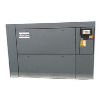
Workplace compressors have no dryer, while Workplace Full-Feature (FF) compressors are provided with an integrated air dryer. The basic version of GA 5 up to GA 11 is equipped with an Elektronikon controller ( see section Elektronikon controller). The Elektronikon® Graphic controller is available as option (see section Elektronikon graphic controller).
-
Page 15
Instruction book Front view, Workplace tank-mounted with Elektronikon® controller Ref. Name Air receiver Air outlet valve Automatic condensate outlet OSD drain outlet (option) Manual condensate drain valve Manual condensate drain valve Elektronikon® controller Emergency stop button Electric cable entry 2920 7090 51… -
Page 16
Instruction book Floor-mounted version The compressors are installed directly on the floor. GA 11 Pack, Floor mounted, Front view Elektronikon® controller Emergency stop button Manual condensate drain valve Automatic condensate outlet 2920 7090 51… -
Page 17
Instruction book Floor-mounted Workplace Pack compressor, rear view Ref. Name Air filter Air outlet valve Combicooler Fan motor Drive motor 2920 7090 51… -
Page 18: Air Flow
Instruction book Air flow Flow diagrams For Workplace units For Workplace Full-Feature units References Ref. Description Intake air Air/oil mixture Hot compressed air 2920 7090 51…
-
Page 19: Oil System
Instruction book Ref. Description Dry air Condensate Dry air (compressors with integrated dryer) Description Air drawn through filter (AF) and open inlet valve (IV) into compressor element (E) is compressed. Compressed air and oil flow into the air receiver/oil separator (OT). The air flows through minimum pressure valve (Vp) to air cooler (Ca).
-
Page 20: Cooling System
Instruction book References Description Intake air Air/oil mixture Compressed air Description The air/oil mixture coming from the compressor element flows into the oil separator/tank, where most of the oil is separated by centrifugal action. The oil collects in the lower part of air receiver/oil separator (OT) which serves as oil tank.
-
Page 21: Condensate System
Instruction book References Description Intake air Compressed air/oil Compressed air Description The cooling system comprises of air cooler (Ca) and oil cooler (Co). The cooling air is generated by a fan (FN). The fan is set on the shaft of the motor. Condensate system Condensate drains Condensate drains on a floor-mounted version…
-
Page 22: Regulating System
Instruction book Regulating system Flow diagram Unloading If the air consumption is less than the air output of the compressor, the net pressure increases. When the net pressure reaches the unloading pressure, solenoid valve (Y1) is de-energised. • The control pressure present in the chambers of loading plunger (LP) and unloading valve (UV) is vented to atmosphere via solenoid valve (Y1).
-
Page 23: Electrical Diagrams
Instruction book Electric cabinet Reference Description Fuses F2-F3 Fuses Overload relay, compressor motor Delta contactor Star contactor Line contactor Transformer Earth terminal Electrical diagrams The service diagram and the explanatory designations below are given as typical example only. Some of the texts may not be applicable to a specific case. The applicable service diagram is situated in the electric cubicle of the compressor.
-
Page 24
Instruction book Service diagram Designations 2920 7090 51… -
Page 25
Instruction book Reference Sensors / solenoid valves / electronic water drain PT20 Pressure sensor, air outlet TT11 Temperature sensor, element outlet TT90 Temperature sensor, dew-point (Full Feature) TT91 Temperature sensor, ambient (Full Feature) Loading solenoid valve Reference Motors Compressor motor Fan motor, cooler Reference Electric cabinet… -
Page 26: Air Dryer
Instruction book Reference Optional equipment R1/K34 Drive motor thermistor protection, shut-down Anti-condensation heaters Auxiliary relay, load/unload signal for ES100 Main power isolating switch Solenoid valve for modulating control Air dryer Flow diagram Air dryer Reference Name Air inlet Air outlet Air/air heat exchanger Air/refrigerant heat exchanger/evaporator Condensate separator…
-
Page 27
Instruction book Reference Name Refrigerant condenser Liquid refrigerant dryer/filter Capillary Hot gas by-pass valve Condenser cooling fan Pressure switch, fan control Compressed air circuit Compressed air enters heat exchanger (1) and is cooled by the outgoing, cold, dried air. Water in the incoming air starts to condense. -
Page 28: Elektronikon® Controller
Instruction book Elektronikon® controller ® Elektronikon regulator Control panel Introduction ® In general, the Elektronikon regulator has following functions: • Controlling the compressor • Protecting the compressor • Monitoring components subject to service • Automatic restart after voltage failure (made inactive) Automatic control of the compressor The regulator maintains the net pressure between programmable limits by automatically loading and unloading the compressor.
-
Page 29: Control Panel
The regulator has a built-in function to automatically restart the compressor when the voltage is restored after voltage failure. This function is deactivated in compressors leaving the factory. If desired, the function can be activated. Consult the Atlas Copco Customer Centre. If activated, and if the regulator was in the automatic operation mode, the compressor will…
-
Page 30: Icons Used On The Display
Instruction book Reference Designation Function LED, Service Is lit when service is needed. Start button This button starts the compressor. Automatic operation LED (3) lights up. The Elektronikon is operative. Stop button This button is used to stop the compressor. Automatic operation LED (3) goes out.
-
Page 31
Instruction book Function Icon Description Units Pressure unit (Mega Pascal) Pressure unit (pounds per square inch) Pressure unit (bar) Temperature unit Temperature unit Hours (always shown together with seconds) Percent The value shown must be multiplied by 10 to get the actual value The value shown must be multiplied by 100 to get the actual value… -
Page 32: Main Screen
The Main screen shows: • The compressor status by means of pictographs • The air outlet pressure Always consult Atlas Copco if the pressure on the display is preceded by a «t». Shut-down warning Description A shut-down warning will appear in the event of: •…
-
Page 33: Dewpoint Temperature
Instruction book • Press Scroll down button (12). The screen shows the temperature at the compressor element outlet: The screen shows that the temperature at the element outlet is 122 °C It remains possible to scroll through other screens, using the Scroll buttons up and down (12) to check the actual status of other parameters.
-
Page 34: Shut-Down
Instruction book Warning screen, dewpoint temperature The screen shows that the dewpoint temperature is 9˚C. • It remains possible to scroll through other screens (using Scroll buttons 12) to check the actual status of other parameters. • Press button (11) to stop the compressor and wait until the compressor has stopped. •…
-
Page 35: Service Warning
Instruction book • Press Scroll buttons (12) until the actual compressor element temperature appears. Shut-down screen, element outlet temperature The screen shows that the temperature at the outlet of the compressor element is 122 ˚C. • Switch off the voltage and remedy the trouble. •…
-
Page 36
In the example above, carry out all service operations belonging to the 8000 running hours interval as well as those belonging to the 4000 running hours interval. • If using mineral oil instead of Atlas Copco Roto-Inject Fluid, the service timer has to be decreased. See section Preventive maintenance schedule. 2920 7090 51… -
Page 37: Scrolling Through All Screens
Instruction book • After servicing, reset the service timer. See section Calling up/resetting the service timer Scrolling through all screens Control panel Control panel Scroll buttons (12) can be used to scroll through all screens. The screens are divided into register screens, measured data screens, digital input screens (numbered as <d.in>, <d.1>, …), parameter screens (numbered as <P.01>, <P.02>, …), protections screens (numbered as <Pr.01>,…) and test screens (numbered as <t.01>,…).
-
Page 38
Instruction book Digital input Designation Related topic screens <d.4> Loading hours (hrs or x1000 hrs) See section Calling up loading hours <d.5> Load relay (x1 or x 1000) See section Calling up Calling up load relay <d.6> Service timer reading (hrs or x 1000 hrs) See section Calling up/resetting the service timer… -
Page 39
Instruction book Test screens Designation Related topic <t.01> Display test See sections Test screens <t.02> Safety valve test See sections Test screens <t.03> Production test See sections Test screens Menu flow Simplified menu flow 2920 7090 51… -
Page 40: Calling Up Outlet And Dewpoint Temperatures
Instruction book Ref. Description Ref. Description Compressor outlet pressure (16) Pressure band setting Compressor outlet temperature (17) Service timer settings Dewpoint temperature (18) Temperature unit Digital input status (19) Unit pressure Running hours (20) Auto restart Motor starts (21) Selection Y-D/DOL Module hours (22) Load delay time…
-
Page 41: Calling Up Running Hours
Instruction book The screen shows that the outlet temperature is 82 ˚C. • For Full-Feature compressors: Press Scroll button (12). The dewpoint temperature will be shown: The screen shows that the dewpoint temperature is 3 ˚C. • Press Scroll button (12) to scroll downwards or upwards through the screens. 3.10 Calling up running hours Control panel Starting from the Main screen:…
-
Page 42: Calling Up Motor Starts
Instruction book The screen shows the unit used (x1000 hrs) and the value (11.25): the running hours of the compressor are 11250 hours. 3.11 Calling up motor starts Control panel Starting from the Main screen: • Press Scroll button (12) until <d.2> is shown and then press Enter button (13): This screen shows the number of motor starts (x 1 or — if <x1000>…
-
Page 43: Calling Up Module Hours
Instruction book 3.12 Calling up module hours Control panel Starting from the Main screen: • Press Scroll button (12) until <d.3> is shown and then press Enter button (13): In the example shown, the screen shows the unit used (hrs) and the value (5000): the regulator module has been in service during 5000 hours.
-
Page 44: Calling Up/Resetting The Service Timer
Instruction book • Press Scroll button (12) until <d.5> is shown and then press Enter button (13): This screen shows the number of unload to load actions (x 1 or — if <x1000> lights up — x 1000). In the above example, the number of unload to load actions is 10100.
-
Page 45: Selection Between Local, Remote Or Lan Control
Instruction book This screen shows the unit used <hrs> (or <x1000 hrs>) and the value <1191>. In the example shown, the compressor has run 1191 hours since the previous service. Resetting the service timer After servicing, see section Service warning, the timer has to be reset: •…
-
Page 46
Instruction book If necessary enter the password. The next screen shows that the function is “ON or OFF” Press the Enter button (13) to change this mode Use the Scroll buttons (12) to select ON or OFF. When this function is ON, use the Scroll buttons up or down (12) to see the node ID. If desired the user can change this ID. -
Page 47: Calling Up/Modifying Ip, Gateway And Subnetmask
Instruction book Press the Enter button (13) to modify the setting. The utmost left value will blink. Change this value by using the Scroll buttons (12). Press the Enter button (13) to confirm. Change the other values in the same way, as required.
-
Page 48
Instruction book Modification Press the Enter button (13) and if necessary enter the password. The first digits are blinking. Use the Scroll buttons Up or Down (12) to modify the settings and press Enter (13) to confirm. Modify the next digits the same way. -
Page 49: Calling Up/Modifying Pressure Band Settings
Instruction book 3.19 Calling up/modifying pressure band settings Calling up the settings Starting from the Main screen: • Press Scroll button (12) until <P.04> is shown and then press Enter button (13). Pressure band 1 (<Pb.1>) is shown on the display. Button (12) can be used to scroll to pressure band 2 (<Pb.2>). •…
-
Page 50: Modifying The Pressure Band Selection
Instruction book Loading pressure Unloading pressure • Press Enter button (13) to modify the load level (value starts blinking). A password may be required. Use Scroll buttons (12) to change the loading pressure. • Press Enter button (13) to program the new values or press the Escape button (14) to cancel. 3.20 Modifying the pressure band selection Control panel 2920 7090 51…
-
Page 51: Calling Up/Modifying Service Timer Settings
Instruction book Starting from the Main screen: • Press Scroll button (12) until <P.05> is shown and then press Enter button (13). The active pressure band 1 (<Pb.1>) is shown on the display. • Press Enter button (13) to modify the pressure band selection (a password may be required). The active pressure band <Pb.1>…
-
Page 52: Calling Up/Modifying Unit Of Pressure
3.24 Activating automatic restart after voltage failure Description This parameter, accessible in screen <P.09>, can only be modified after entering a code. Consult Atlas Copco if this function is to be activated. 3.25 Selection between Y-D or DOL starting…
-
Page 53: Calling Up Modifying Load Delay Time
Instruction book • This parameter can only be modified after entering a code. Consult Atlas Copco if the parameter is to be changed. 3.26 Calling up modifying load delay time Control panel Starting from the Main screen: • Press Scroll button (12) until <P.11> and the compressor load pictograph is shown and press the Enter button (13): •…
-
Page 54: Activating Password Protection
Instruction book • Press the Scroll button (12) until <P.12> and the motor pictograph is shown and press the Enter button (13): • This screen shows the minimum stop time (20) and the unit <s> (seconds). • To modify this value press the Enter button (13). The value starts blinking and Scroll buttons (12) can be used to modify this value.
-
Page 55: Calling Up/Modifying Protection Settings
Instruction book • Press the Enter button (13). • The function of this screen is to activate the remote load/unload relay. To be able to activate this remote Load/Unload functionality, a physical digital input with function Load/Unload is required. Once this parameter is activated, the physical digital input can be used to switch the compressor between Load and Unload.
-
Page 56
Instruction book • A low warning level, shown on the display as <AL-L>. • A high warning level, shown on the display as <AL-H>. • A low shut-down level, shown on the display as <Sd-L>. • A high shut-down level, shown on the display as <Sd-H>. •… -
Page 57: Test Screens
Safety valve test In the test screen <t.02> a safety valve test is provided. The safety valves can only be tested after entering a code. Consult Atlas Copco if the safety valves are to be tested. Production test Test screen <t.03> is only intended for production test. If the Main screen shows following screen, the…
-
Page 58: Web Server
Instruction book 3.32 Web server All Elektronikon controllers have a built-in web server that allows direct connection to a PC via a local area network (LAN). This allows to consult certain data and settings via the PC instead of via the display of the controller.
-
Page 59
Instruction book • Click on View Network connections (1). • Select the Local Area connection (1), which is connected to the controller. • Click with the right button and select properties (1). 2920 7090 51… -
Page 60
Instruction book • Use the checkbox Internet Protocol (TCP/IP) (1) (see picture). To avoid conflicts, de-select other properties if they are selected. After selecting TCP/IP, click on the Properties button (2) to change the settings. • Use the following settings: •… -
Page 61
Instruction book • Click on the Connections tab (1) and then click on the LAN settings button (2). • In the Proxy server Group box, click on the Advanced button (1). 2920 7090 51… -
Page 62
Instruction book • In the Exceptions Group box, enter the IP address of your controller. Multiple IP addresses can be given but they must be separated with semicolons (;). Example: Suppose that you already added two IP addresses (192.168.100.1 and 192.168.100.2). Now you add 192.168.100.100 and separate the 3 IP addresses by putting semicolons between them (1) (see picture). -
Page 63
Instruction book Navigation and options • The banner shows the compressor type and the language selector. In this example, three languages are installed on the controller. • On the left site of the interface you can find the navigation menu (see picture below). If a license for ESi is foreseen, the menu contains 3 buttons. -
Page 64
Instruction book Compressor settings All compressor settings can be hidden or shown. Put a mark for each setting. Only the machine status is fixed and can not be removed from the main screen. Analog inputs (The units of measure can be changed in the preference button from the navigation menu). Counters Counters give an overview of all actual counters from controller and compressor. -
Page 65
Instruction book Digital outputs Shows a list of all digital outputs and their status. Special protections Give an overview of all special protections of the compressor. Service plan Shows all levels of the service plan and status. This screen only shows the running hours. It is also possible to show the actual status of the service interval. -
Page 66: Programmable Settings
Instruction book A possible ESi screen 3.33 Programmable settings Parameters: unloading/loading pressures for compressors without built-in refrigeration dryer Minimum Factory Maximum setting setting setting Unloading pressures Unloading pressure (7.5 bar compressors) bar(e) Unloading pressure (7.5 bar compressors) psig 101.5 108.8 Unloading pressure (8.5 bar compressors) bar(e) Unloading pressure (8.5 bar compressors)
-
Page 67
Instruction book Minimum Factory Maximum setting setting setting Loading pressure (13 bar compressors) psig 172.6 187.1 Loading pressure (100 psi compressors) bar(e) Loading pressure (100 psi compressors) psig 91.4 105.9 Loading pressure (125 psi compressors) bar(e) Loading pressure (125 psi compressors) psig 130.5 Loading pressure (150 psi compressors) -
Page 68
Also see section Preventive maintenance schedule. Consult Atlas Copco if a timer setting has to be changed. See section Calling up/modifying service timer settings. The intervals must not exceed the nominal intervals and must coincide logically. 2920 7090 51… -
Page 69
Minimum stop Once the compressor has automatically stopped, it will remain stopped for the minimum time stop time, whatever happens with the net air pressure. Consult Atlas Copco if a setting lower than 20 seconds is required. Unloading/ The regulator does not accept illogical settings, e.g. if the unloading pressure is Loading pressure programmed at 7.0 bar(e) (101 psi(g)), the maximum limit for the loading pressure changes… -
Page 70: Elektronikon® Graphic Controller
Instruction book Elektronikon® Graphic controller ® Elektronikon Graphic controller Control panel ® Display of the Elektronikon Graphic controller Introduction The Elektronikon controller has following functions: • Controlling the compressor • Protecting the compressor • Monitoring components subject to service • Automatic restart after voltage failure (made inactive) Automatic control of the compressor operation The regulator maintains the net pressure between programmable limits by automatically loading and unloading the compressor.
-
Page 71: Protecting The Compressor
The regulator has a built-in function to automatically restart the compressor if the voltage is restored after voltage failure. For compressors leaving the factory, this function is made inactive. If desired, the function can be activated. Consult the Atlas Copco Customer Centre. If activated and provided the regulator was in the automatic operation mode, the compressor will automatically restart if the supply voltage to the module is restored.
-
Page 72: Control Panel
Instruction book Control panel Elektronikon regulator Control panel Parts and functions Reference Designation Function Display Shows the compressor operating condition and a number of icons to navigate through the menu. Pictograph Automatic operation Pictograph General alarm General alarm LED Flashes if a shut-down warning condition exists. Pictograph Service Service LED…
-
Page 73: Icons Used
Instruction book Icons used Status icons Name Icon Description Stopped / Running When the compressor is stopped, the icon stands still. When the compressor is running, the icon is rotating. Compressor status Motor stopped Running unloaded Running loaded Machine control mode Local start / stop Remote start / stop Network control…
-
Page 74
Instruction book Input icons Icon Description Pressure temperature Digital input Special protection System icons Icon Description Compressor element (LP, HP, …) Dryer Frequency converter Drain Filter Motor Failure expansion module Network problem General alarm 2920 7090 51… -
Page 75
Instruction book Menu icons Icon Description Inputs Outputs Alarms (Warnings, shutdowns) Counters Test Settings Service Event history (saved data) Access key / User password Network Setpoint Info Navigation arrows Icon Description Down 2920 7090 51… -
Page 76: Main Screen
Instruction book Main screen Control panel Scroll keys Enter key Escape key Function The Main screen shows the status of the compressor operation and is the gateway to all functions implemented in the controller. The Main screen is shown automatically when the voltage is switched on and one of the keys is pushed. It is switched off automatically after a few minutes when no keys are pushed.
-
Page 77
Instruction book Text on figures Compressor Outlet Element Outlet (fixed speed compressors) Flow in % (compressors with frequency converter) Load (text varies upon the compressors actual condition) Menu Unload (text varies upon the compressors actual condition) • Section A shows information regarding the compressor operation (e.g. the outlet pressure (1), the temperature at the compressor outlet (2)). -
Page 78: Calling Up Menus
Instruction book Calling up menus Control panel Control panel Scroll keys Enter key Escape key Description When the voltage is switched on, the main screen is shown automatically (see section Main screen): • To go to the Menu screen, highlight the Menu button (3), using the Scroll keys. •…
-
Page 79: Inputs Menu
Instruction book • Press the Escape key to return to the Main screen. Inputs menu Control panel Scroll keys Enter key Escape key Menu icon, Inputs Function To call up information regarding the actually measured data and the status of some inputs such as the emergency stop switch.
-
Page 80: Outputs Menu
Instruction book Menu Regulation • Using the Scroll keys, move the cursor to the Inputs icon (see above, section Menu icon). • Press the Enter key. A screen similar to the one below appears: Text on figure Inputs Compressor outlet Element outlet Ambient air Emergency stop…
-
Page 81
Instruction book Menu icon, Outputs Function To call up information regarding the actual status of some outputs such as the condition of the Fan overload contact (on air cooled compressors), the Emergency stop contact, etc. Procedure Starting from the Main screen (see Main screen), •… -
Page 82: Counters
Instruction book Counters Control panel Scroll keys Enter key Escape key Menu icon, Counters Function To call up: • The running hours • The loaded hours • The number of motor starts • The number of hours that the regulator has been powered •…
-
Page 83: Service Menu
Instruction book Menu Regulation • Using the Scroll keys, move the cursor to the Counters icon (see above, section Menu icon) • Press the Enter key. Following screen appears: Text on figure Counters Running hours Motor starts Load relay VSD 1-20 % rpm in % (the percentage of the time during which the motor speed was between 1 and 20 %) (compressors with frequency converter) The screen shows a list of all counters with their actual readings.
-
Page 84
Instruction book Menu icon, Service Function • To reset the service plans which are carried out. • To check when the next service plans are to be carried out. • To find out which service plans were carried out in the past. •… -
Page 85
Instruction book Overview Text on figure Overview Running Hours (green) Real Time hours (blue) Reset Example for service level (A): The figures at the left are the programmed service intervals. For Service interval A, the programmed number of running hours is 4000 hours (upper row, green) and the programmed number of real time hours is 8760 hours, which corresponds to one year (second row, blue). -
Page 86
Instruction book Service plan Level Running hours Real time hours Modify Modifying a service plan Dependant on the operating conditions, it can be necessary to modify the service intervals. To do so, use the Scroll keys to select the value to be modified. A screen similar to the one below appears: Press the Enter key. -
Page 87: Setpoint Menu
Instruction book Next service Level Running hours Actual In the example above, the A Service level is programmed at 4000 running hours, of which 0 hours have passed. History The History screen shows a list of all service actions done in the past, sorted by date. The date at the top is the most recent service action.
-
Page 88
Instruction book Text on figure Menu Regulation • Move the cursor to the Setpoint icon (see above, section menu icon) using the Scroll keys. • Press the Enter key. Following screen appears: Text on figure Regulation Unloading pressure 1 Loading pressure 1 Unloading pressure 2 Loading pressure 2 Modify… -
Page 89: Event History Menu
Instruction book • The upper and lower limit of the setting is shown in grey, the actual setting is shown in black. Use the ↑ or ↓ key of the Scroll keys to modify the settings as required and press the Enter key to accept. If necessary, change the other settings as required in the same way as described above.
-
Page 90: Modifying General Settings
Instruction book • Using the Scroll keys, move the cursor to the Event History icon (see above, section Menu icon) • The list of last shut-down and emergency stop cases is shown. • Scroll through the items to select the desired shut-down or emergency stop event. •…
-
Page 91: Info Menu
Instruction book • Using the Scroll keys, move the cursor to the Settings icon (see above, section menu icon). • Press the Enter key. Following screen appears: Text on figure General Language used Time Date Date format Modify • To modify, select the Modify button using the Scroll keys and press the Enter key. •…
-
Page 92: Week Timer Menu
• Move the cursor to the action button Menu and press the Enter key. Following screen appears: • Using the Scroll keys, move the cursor to the Info icon (see above, section Menu icon). • Press the Enter key. The Atlas Copco internet address appears on the screen. 4.14 Week timer menu…
-
Page 93
Instruction book Scroll keys Enter key Escape key Menu icon, Week timer Function • To program time-based start/stop commands for the compressor • To program time-based change-over commands for the net pressure band • Four different week schemes can be programmed. •… -
Page 94
Instruction book Week Timer Week Action Schemes Week Cycle Status Week Timer Inactive Remaining Running Time The first item in this list is highlighted in red. Select the item requested and press the Enter key on the controller to modify. Programming week schemes •… -
Page 95
Instruction book Friday Saturday Sunday • A new window opens. The Modify action button is selected. Press the enter button on the controller to create an action. Monday Modify • A new pop-up window opens. Select an action from this list by using the Scroll keys on the controller. When ready press the Enter key to confirm. -
Page 96
Instruction book Monday Start Save Modify • To adjust the time, use the Scroll keys on the controller and press the Enter key to confirm. Monday Start Save Modify • A pop-up window opens. Use the ↑ or ↓ key of Scroll keys to modify the values of the hours. Use the ← or →… -
Page 97
Instruction book • Press the Escape key on the controller. The action button Modify is selected. Use the Scroll keys to select the action Save. Monday Start Save Modify • A new pop-up window opens. Use the Scroll keys on the controller to select the correct actions. Press the Enter key to confirm. -
Page 98
Instruction book Week Action Scheme 1 Monday — Start Tuesday Wednesday Thursday Friday Saturday Sunday Press the Escape key on the controller to leave this screen. Programming the week cycle A week cycle is a sequence of 10 weeks. For each week in the cycle, one of the four programmed week schemes can be chosen. -
Page 99
Instruction book Week 2 Week 3 Week 4 Modify Press twice the Enter key on the controller to modify the first week. • A new window opens. Select the action, example: Week Action Scheme 1 Week Cycle Week 1 Week Action Scheme 1 Week Action Scheme 2 Week Action Scheme 3 Modify… -
Page 100
Instruction book Week Timer Week Week Timer Inactive Week 1 • Press the Escape key on the controller to leave this window. The status shows that week 1 is active. Week Timer Week Action Schemes Week Cycle Status Remaining Running Time •… -
Page 101: Test Menu
Instruction book Week Timer Week Action Schemes Week Cycle Status Remaining Running Time • This timer is used when the week timer is set and for certain reasons the compressor must continue working, for example, 1 hour, it can be set in this screen. This timer is prior to the Week Timer action. Week Timer Week action schemes Remaining Running Time…
-
Page 102: User Password Menu
Instruction book Procedure Starting from the Main screen (see Main screen): • Move the cursor to the action button Menu and press the enter key (2), following screen appears: • Using the scroll keys (1), move the cursor to the test icon (see above, section Menu icon) •…
-
Page 103: Web Server
Instruction book Menu icon, Password Function If the password option is activated, it is impossible for not authorized persons to modify any setting. Procedure Starting from the Main screen (see Main screen), • Move the cursor to the action button Menu and press the Enter key. Following screen appears: •…
-
Page 104
Instruction book Configuration of the network card • Go to My Network places (1). • Click on View Network connections (1). • Select the Local Area connection (1), which is connected to the controller. 2920 7090 51… -
Page 105
Instruction book • Click with the right button and select properties (1). • Use the checkbox Internet Protocol (TCP/IP) (1) (see picture). To avoid conflicts, de-select other properties if they are selected. After selecting TCP/IP, click on the Properties button (2) to change the settings. •… -
Page 106
Instruction book • When using Internet Explorer: Open Internet Explorer and click on Tools — Internet options (2). • Click on the Connections tab (1) and then click on the LAN settings button (2). • In the Proxy server Group box, click on the Advanced button (1). 2920 7090 51… -
Page 107
Instruction book • In the Exceptions Group box, enter the IP address of your controller. Multiple IP addresses can be given but they must be separated with semicolons (;). Example: Suppose that you already added two IP addresses (192.168.100.1 and 192.168.100.2). Now you add 192.168.100.100 and separate the 3 IP addresses by putting semicolons between them (1) (see picture). -
Page 108
Instruction book Navigation and options • The banner shows the compressor type and the language selector. In this example, three languages are installed on the controller. • On the left site of the interface you can find the navigation menu (see picture below). If a license for ESi is foreseen, the menu contains 3 buttons. -
Page 109
Instruction book Compressor settings All compressor settings can be hidden or shown. Put a mark for each setting. Only the machine status is fixed and can not be removed from the main screen. Analog inputs (The units of measure can be changed in the preference button from the navigation menu). Counters Counters give an overview of all actual counters from controller and compressor. -
Page 110
Instruction book Digital outputs Shows a list of all digital outputs and their status. Special protections Give an overview of all special protections of the compressor. Service plan Shows all levels of the service plan and status. This screen only shows the running hours. It is also possible to show the actual status of the service interval. -
Page 111: Programmable Settings
Instruction book A possible ESi screen 4.18 Programmable settings Parameters: unloading/loading pressures for compressors without built-in refrigeration dryer Minimum Factory Maximum setting setting setting Unloading pressures Unloading pressure (7.5 bar compressors) bar(e) Unloading pressure (7.5 bar compressors) psig 101.5 108.8 Unloading pressure (8.5 bar compressors) bar(e) Unloading pressure (8.5 bar compressors)
-
Page 112
Instruction book Minimum Factory Maximum setting setting setting Loading pressure (13 bar compressors) psig 172.6 187.1 Loading pressure (100 psi compressors) bar(e) Loading pressure (100 psi compressors) psig 91.4 105.9 Loading pressure (125 psi compressors) bar(e) Loading pressure (125 psi compressors) psig 130.5 Loading pressure (150 psi compressors) -
Page 113
The built-in service timers will give a Service warning message after their respective preprogrammed time interval has elapsed. Also see section. Consult Atlas Copco if a timer setting has to be changed. The intervals must not exceed the nominal intervals and must coincide logically. See section Modifying general settings. -
Page 114
Minimum stop Once the compressor has automatically stopped, it will remain stopped for the minimum time stop time, whatever happens with the net air pressure. Consult Atlas Copco if a setting lower than 20 seconds is required. Unloading/ The regulator does not accept inconsistent settings, e.g. if the unloading pressure is Loading pressure programmed at 7.0 bar(e) (101 psi(g)), the maximum limit for the loading pressure changes… -
Page 115: Osd Oil/Condensate Separator (Optional)
Instruction book OSD oil/condensate separator (optional) OSD unit Oil/condensate separators Compressed air leaving oil-injected compressors contains oil. During cooling of this air, oil-containing condensate is formed. OSD are designed to separate the major part of this oil from the condensate and to catch the oil in a collector.
-
Page 116: Operating And Maintenance Instructions
Instruction book Operation Condensate containing fine oil droplets flows via a strainer (5) through filter (3), in which the droplets coalesce into larger drops. The condensate is then led to vessel (1) where the oil rises due to the difference in specific mass.
-
Page 117: Pictographs
Instruction book Condensate drains Maintenance instructions Consult section OSD unit for the references. Interval Running hours Operation Weekly Check pressure gauge (2). If the pressure reaches 2 bar(e) (29 psig) or every 6000 operating hours, replace filter (3): Unscrew the filter. Fill the new filter with water, lightly oil its gasket, screw it on and tighten by hand (approx.
-
Page 118
Instruction book Reference Description Consult instruction book before maintenance or repair 2920 7090 51… -
Page 119: Installation
Instruction book Installation Dimension drawings Drawings GA 5 up to GA 11 Pack, Floor mounted 2920 7090 51…
-
Page 120
Instruction book GA 5 up to GA 11 Pack on 270 l air receiver 2920 7090 51… -
Page 121
Instruction book GA 5 up to GA 11 Full-Feature, Floor mounted 2920 7090 51… -
Page 122
Instruction book GA 5 up to GA 11 Full-Feature on 270 l air receiver 2920 7090 51… -
Page 123
Instruction book GA 5 up to GA 11 Pack on 500 l air receiver 2920 7090 51… -
Page 124
Instruction book GA 5 up to GA 11 Full-Feature on 500 l air receiver Reference Designation Compressor and motor cooling air inlet Dryer cooling air outlet Dryer air inlet Compressed air outlet Compressor air inlet 2920 7090 51… -
Page 125: Installation Proposal
Outdoor/altitude operation If the compressor is installed outdoors or if the air inlet temperature can be below 0 ˚C (32 ˚F), precautions must be taken. In this case, and also if operating above 1000 m (3300 ft), consult Atlas Copco. Moving/lifting To transport the compressor with a forklift truck, use the openings in the frame.
-
Page 126
Instruction book Installation proposal Compressor room example Text on drawing Reference Designation Ventilation proposals Minimum free area to be reserved for the compressor installation 2920 7090 51… -
Page 127: Installation Guidelines
5. The drain pipes to the drain collector must not dip into the water of the drain collector. Atlas Copco has oil/water separators (type OSD) to separate the major part of the oil from the condensate to ensure that the condensate meets the requirements of the environmental codes.
-
Page 128: Electrical Connections
Instruction book . If oil vapours and odours are undesirable, a QD type filter should be installed downstream of the PD filter. It is recommended to provide by-pass pipes and valves across the filters in order to isolate the filters during maintenance without disturbing the compressor.
-
Page 129
Connect the power supply cables to terminals L1, L2 and L3 (1X0) and the neutral conductor (if applicable) to terminal (N). Connect the earth conductor. Specific instructions for GA 5 up to GA 11 with 208 V/ 230 V / 460 V cubicle Always disconnect the power supply before working on the electrical circuit! The standard voltage configuration for the compressor is mentioned on the data plate of the machine. -
Page 130
Instruction book To modify the wiring for an operating voltage of 208 V or 460 V, compressor main cubicle and transformer dryer cubicle should be rewired as described below: Required modifications in the compressor cubicle: Step Action Adjust the motor overload (FM1) setting. Rewire the control transformer (T1). -
Page 131
Instruction book Adjustment screw of the motor overload Motor overload (FM1) setting GA 5 GA 7 GA 11 208 V 33.0 43.0 61.0 230 V (standard factory setting) 30.0 39.0 55.0 460 V 15.0 19.0 27.5 To rewire the control transformer (T1), move the wire of the transformer to the terminal marked with the desired voltage (208 V, 230 V or 460 V). -
Page 132
The Elektronikon regulator is provided with an auxiliary relay (K05) for remote indication of a shutdown. Maximum load for the contacts: 10 A / 250 V AC. Stop the compressor and switch off the voltage before connecting external equipment. Consult Atlas Copco. Compressor status indication on compressors equipped with an Elektronikon® Graphic controller The Elektronikon regulator is provided with auxiliary contacts (K05, K07 and K08) for remote indication of: •… -
Page 133: Pictographs
39 of terminal (2×27) (input DIO4 on the controller). This results in loading and unloading of the compressor at the closing and opening pressures of the external pressure switch respectively. • LAN control: The compressor is controlled via a local network. Consult Atlas Copco. See section Electrical system to locate the connectors.
-
Page 134
Instruction book Reference Designation Warning: before connecting compressor electrically, consult Instruction book for motor rotation direction Torques for steel (Fe) or brass (CuZn) bolts Consult instruction book before greasing Lightly oil gasket of oil filter, screw it on and tighten by hand (approx. half a turn) 2920 7090 51… -
Page 135: Operating Instructions
Instruction book Operating instructions Initial start-up Safety The operator must apply all relevant Safety precautions. Procedure For the position of the air outlet valve and the drain connections, see sections Introduction Condensate system. 1. Consult the sections Electric cable size,Installation proposals Dimension drawings 2.
-
Page 136
Position of oil level sight-glass 8. Provide labels, warning the operator that: • The compressor may automatically restart after voltage failure (if activated, consult Atlas Copco). • The compressor is automatically controlled and may be restarted automatically. 2920 7090 51… -
Page 137: Before Starting
Instruction book • Affix the above sheet explaining the procedure for checking the motor rotation direction to the cooling air outlet of the compressor. • Check the rotation direction of the motor using the sheet. If the motor rotation direction is correct, the sheet on the top grating will be blown upwards.
-
Page 138: Starting
Instruction book Starting Procedure For the position of the air outlet valve and the drain connections, see sections Introduction Condensate system Control panel of the Elektronikon® controller Control panel of the Elektronikon® Graphic controller Step Action Switch on the voltage. Check that voltage on LED (6) lights up. Open the air outlet valve.
-
Page 139: During Operation
Instruction book During operation Procedure Control panel of the Elektronikon® controller Control panel of the Elektronikon® Graphic controller 2920 7090 51…
-
Page 140
Instruction book Position of oil level sight-glass and service indicator Regularly check the oil level: Approximately three minutes after stopping, sight-glass (Gl) should be between 1/4 and 3/4 full. If the level is too low, stop the compressor, wait until the compressor has stopped, depressurise the oil system by unscrewing oil filler plug (FC) one turn and wait a few minutes. -
Page 141: Checking The Display
Instruction book Checking the display Procedure Control panel of the Elektronikon® controller Control panel of the Elektronikon® Graphic controller Compressors with Elektronikon® controller: Check the display (2) regularly for readings and messages. The display normally shows the compressor outlet pressure, while the status of the compressor is indicated by pictographs. Remedy the trouble if alarm LED (7) is lit or flashes, see section Shutdown warning Shutdown…
-
Page 142: Stopping
Instruction book Stopping Elektronikon regulator Control panel of the Elektronikon® controller Control panel of the Elektronikon® Graphic controller Air outlet valve 2920 7090 51…
-
Page 143: Taking Out Of Operation
Instruction book Condensate drain valve, Tank-mounted GA 5 up to GA 11 Procedure Step Action Press stop button (9). Automatic operation LED (8) goes out and the compressor stops after 30 seconds of unloaded operation. To stop the compressor in the event of an emergency, press emergency stop button (10).
-
Page 144
Instruction book Step Action Drain the condensate circuit and disconnect the condensate piping from the condensate net. Air outlet valve Condensate drain valve, Tank-mounted GA 5 up to GA 11 2920 7090 51… -
Page 145: Maintenance
For overhauling or carrying out preventive maintenance, service kits are available (see section Service kits). Service contracts Atlas Copco offers several types of service contracts, relieving you of all preventive maintenance work. Consult your Atlas Copco Customer Centre. General When servicing, replace all removed gaskets, O-rings and washers.
-
Page 146
Instruction book Service plans for compressors with an Elektronikon® Graphic controller Besides the daily and 3-monthly checks, preventive service operations are specified in the schedule below. Each plan has a programmed time interval at which all service actions belonging to that plan are to be carried out. -
Page 147
(2): or every 2 years, whichever comes first Test button on the EWD Important • Always consult Atlas Copco if a service timer setting has to be changed. • For the change interval of oil and oil filter in extreme conditions, consult your Atlas Copco Customer Centre. -
Page 148: Oil Specifications
It is strongly recommended to use genuine Atlas Copco Lubricants. They are the result of years of field experience and research in our labs. See section Preventive maintenance schedule for replacement intervals and section Service Kits for part number information.
-
Page 149: Service Kits
Service kits For overhauling and for preventive maintenance, a wide range of service kits is available. Service kits comprise all parts required for servicing the component and offer the benefits of genuine Atlas Copco parts while keeping the maintenance budget low.
-
Page 150: Adjustments And Servicing Procedures
Instruction book Adjustments and servicing procedures Drive motor General Keep the outside of the electric motor clean for efficient cooling. If necessary, remove dust with a brush and/ or compressed air jet. Bearing maintenance The motor bearings are greased for life. Air filter Location of air filter Air filter…
-
Page 151: Oil And Oil Filter Change
Instruction book Oil and oil filter change Warning The operator must apply all relevant Safety precautions. Procedure Oil system components 1. Run the compressor until warm. Stop the compressor. Close the air outlet valve and switch off the voltage. Depressurise the compressor by opening manual drain valve(s) (Dm, Dm1). Wait a few minutes and depressurise the air receiver/oil (AR) tank by unscrewing oil filler plug (FC) just one turn to permit any pressure in the system to escape.
-
Page 152: Oil Separator Change
Instruction book Add oil until the sight-glass (Gl) is 3/4 full. Tighten the filler plug. 8. Reset the service warning after carrying out all service actions in the relevant Service Plan: For compressors with Elektronikon® controller, see section Calling up/resetting the service timer.
-
Page 153: Coolers
• Next, clean with an air jet in the reverse direction to normal flow. Use low pressure air. If necessary, the pressure may be increased up to 6 bar(e) (87 psig). • If it is necessary to wash the coolers with a cleaning agent, consult Atlas Copco. Belt tensioning and replacement…
-
Page 154
Refit the bodywork panels. Replacing the belts The belts must always be replaced as a set, even if only one of the belts is worn. Only use genuine Atlas Copco belts. Step Action Stop the compressor, close the air outlet valve and switch off the voltage. -
Page 155: Safety Valves
Instruction book Step Action Refit the bodywork panels. Check the belt tension after 50 running hours and adjust if necessary. Safety valves Location of safety valve Safety valve on oil separator vessel Safety valve on oil separator vessel 2920 7090 51…
-
Page 156: Dryer Maintenance Instructions
Instruction book Safety valve on compressed air vessel Testing Before removing the valve, depressurise the compressor. See section Problem solving. Valve (SV) can be tested on a separate air line. If the valve does not open at the set pressure stamped on the valve, it needs to be replaced.
-
Page 157
Instruction book Local legislation Local legislation may stipulate that: • Work on the refrigerant circuit of the cooling dryer or on any equipment which influences its function must be undertaken by an authorised control body. • The installation should be checked once a year by an authorised control body. General For all references see section Introduction. -
Page 158: Problem Solving
Instruction book Problem solving Warning Before carrying out any maintenance, repair work or adjustment, press the stop button, wait until the compressor has stopped, press the emergency stop button and switch off the voltage. Close the air outlet valve and lock it if necessary. If provided, open the manual condensate drain valves.
-
Page 159
Oil cooler clogged Clean cooler Thermostatic bypass valve Have valve tested malfunctioning Air cooler clogged Clean cooler Compressor element out of order Consult Atlas Copco Customer Centre Oil filter clogged Replace Dryer For all references hereafter, consult section dryer. 2920 7090 51… -
Page 160
Instruction book Condition Fault Remedy Pressure dewpoint too high Air inlet temperature too high Check and correct; if necessary, clean the aftercooler of the compressor Ambient temperature too high Check and correct; if necessary, draw cooling air via a duct from a cooler place or relocate the compressor Shortage of refrigerant Have circuit checked for leaks and… -
Page 161: Technical Data
Instruction book Technical data 11.1 Readings on display Elektronikon Control panel of the Elektronikon® controller Control panel of the Elektronikon® Graphic controller Important The readings mentioned below are valid under the reference conditions (see section Reference conditions and limitations). Reference Reading Air outlet pressure Modulates between programmed unloading and loading pressures.
-
Page 162: Electric Cable Size
Instruction book 11.2 Electric cable size Important warning The compressor is delivered with 3 m (10 ft.) cable and cable gland. This cable gland is necessary to ensure the protection degree of the electric cubicle and to protect its components from dust from the environment. •…
-
Page 163
If the local conditions are more severe then the described standard conditions, the cables and fuses for worst case conditions should be used. Cable size Type Approval Recommended wire section (mm Pack Full Feature GA 5 4 x 6 4 x 10 GA 5 4 x 6 4 x 10 GA 5 4 x 2.5… -
Page 164: Settings For Overload Relay And Fuses
Instruction book Type Approval Recommended wire section (AWG) Pack Full Feature GA 5 CSA/UL GA 5 200/230/460 CSA/UL GA 5 CSA/UL GA 7 CSA/UL GA 7 200/230/460 CSA/UL GA 7 CSA/UL GA 11 CSA/UL GA 11 200/230/460 CSA/UL GA 11 CSA/UL 11.3 Settings for overload relay and fuses…
-
Page 165: Dryer Switches
GA 11 400 + N GA 11 GA 11 Type Approval Overload Fuse rating (A) setting (FM1) Class J or RK Pack Full Feature GA 5 CSA/UL 34.5 GA 5 200/230/460 CSA/UL 33/30/15 40/40/20 40/40/20 GA 5 CSA/UL GA 7 CSA/UL 44.5…
-
Page 166: Compressor Data
˚F 11.6 Compressor data Reference conditions All data specified below are valid at reference conditions, see section Reference conditions limitations. GA 5 Units 7.5 bar 8.5 bar 10 bar 13 bar 100 psi 125 psi 150 psi 175 psi Frequency…
-
Page 167
Instruction book Units 7.5 bar 8.5 bar 10 bar 13 bar 100 psi 125 psi 150 psi 175 psi Pressure drop over psig 1.45 1.16 0.72 1.45 1.16 0.72 dryer, Full-Feature units Motor shaft speed r/min 2900 2900 2900 2900 3510 3510 3510… -
Page 168
Instruction book Units 7.5 bar 8.5 bar 10 bar 13 bar 100 psi 125 psi 150 psi 175 psi Oil capacity US gal 0.95 0.95 0.95 0.95 0.95 0.95 0.95 0.95 Oil capacity Imp gal 0.79 0.79 0.79 0.79 0.79 0.79 0.79 0.79… -
Page 169
Instruction book Units 7.5 bar 8.5 bar 10 bar 13 bar 100 psi 125 psi 150 psi 175 psi Temperature of air ˚F leaving outlet valve (approx.) Temperature of air ˚C leaving outlet valve (approx.), Full- Feature units Temperature of air ˚F leaving outlet valve (approx.), Full-… -
Page 170
Instruction book Units 7.5 bar 8.5 bar 10 bar 13 bar 100 psi 125 psi 150 psi 175 psi Maximum bar(e) 10.8 12.5 (unloading) pressure, units without dryer Maximum psig (unloading) pressure, units without dryer Maximum bar(e) 7.25 8.25 9.75 12.75 7.15 8.85… -
Page 171: Technical Data Elektronikon® Controller
Instruction book Units 7.5 bar 8.5 bar 10 bar 13 bar 100 psi 125 psi 150 psi 175 psi Dew-point, Full- ˚F 37.4 37.4 37.4 37.4 37.4 37.4 37.4 37.4 Feature units Nominal motor rating kW Nominal motor rating hp 14.75 14.75 14.75…
-
Page 172: Analog Inputs
Instruction book Noise immunity IEC61000-6-2 Mounting Cabinet door Digital outputs Parameter Value Number of outputs 6 (Elektronikon® controller — p.n. 1900 5200 00 …. 1900 5200 9 ( Elektronikon® Graphic controller — p.n. 1900 5200 10 …. 1900 5200 19) Type Relay (voltage free contacts) Rated voltage AC…
-
Page 173: Instructions For Use
Instruction book Instructions for use Oil separator vessel This vessel can contain pressurised air; this can be potentially dangerous if the equipment is misused. This vessel must only be used as a compressed air/oil separator tank and must be operated within the limits specified on the data plate.
-
Page 174: Guidelines For Inspection
Instruction book Guidelines for inspection Guidelines On the Declaration of Conformity / Declaration by the Manufacturer, the harmonised and/or other standards that have been used for the design are shown and/or referred to. The Declaration of Conformity / Declaration by the Manufacturer is part of the documentation that is supplied with this compressor.
-
Page 175: Pressure Equipment Directives
II and higher according to the Pressure Equipment Directive 97/23/EC and all pressure equipment according to the Simple Pressure Vessel Directive 87/404/EEC. Compressor type Part number Description PED Class GA 5 up to GA 11 2202 8891 01 Safety valve 2202 8891 03 Safety valve 2202 8891 02…
-
Page 176: Declaration Of Conformity
Instruction book Declaration of conformity Typical example of a Declaration of Conformity document 2920 7090 51…
-
Page 178
Atlas Copco’s pursuit of innovation never ceases, driven by our need for reliability and efficiency. Always working with you, we are committed to providing you the customized quality air solution that is the driving force behind your business.
- Manuals
- Brands
- Atlas Copco Manuals
- Air Compressor
ManualsLib has more than 381 Atlas Copco Air Compressor manuals
Click on an alphabet below to see the full list of models starting with that letter:
8
A
C
E
G
L
M
O
P
S
U
W
X
Z
Popular manuals
39 pages
GA11 Instruction Book
31 pages
GA55 User Manual

36 pages
ga37 User Manual
45 pages
GA5 User Manual
128 pages
GA 37 VSD Instruction Book

76 pages
GX 7 Instruction Book
178 pages
GA 5 Instruction Book
98 pages
GA 55+ Instruction Book
108 pages
GA 15 Instruction Book
45 pages
GA5 User Manual
66 pages
ZT Series Instruction Book
88 pages
XAMS 407 CD Instruction Manual
70 pages
Air Compressor Instruction Book
166 pages
GA 110 VSD Instruction Book
41 pages
GA90 Instruction Book
150 pages
ga55+ Instruction Book

94 pages
GA 18 Instruction Book
29 pages
GA18 VSD Instruction Book
20 pages
GA90 Instruction Book

138 pages
GA 7 VSD+ Instruction Book
Models
Document Type
8
8115410428

Instruction Book
A
Air Compressor
Instruction Book
APF221384
Original Instruction Book
AUTOMAN AC100
Instruction Manual
AUTOMAN AC100E500T
Instruction Manual
AUTOMAN AC100E500TS
Instruction Manual
AUTOMAN AC100T500T
Instruction Manual
AUTOMAN AC100T500TS
Instruction Manual
AUTOMAN AC40
Instruction Manual
AUTOMAN AC40T300T
Instruction Manual
AUTOMAN AC55E300T
Instruction Manual
AUTOMAN AC55E300TS
Instruction Manual
AUTOMAN AC55E500T
Instruction Manual
AUTOMAN AC55E500TS
Instruction Manual
AUTOMAN AC55T500T
Instruction Manual
AUTOMAN AC55T500TS
Instruction Manual
C
CR Series
Instruction Book
CRC10
Instruction Book
CRC15
Instruction Book
CRC20
Instruction Book
CRI10
Instruction Book
CRI15
Instruction Book
CRI5
Instruction Book
CRI7.5
Instruction Book
CRP20
Instruction Book
E
Elektronikon II
User Manual
G
G 15L
Instruction Book
G 160 VSD
Original Instruction Book
G 18
Instruction Book
G 2
Instruction Book
G 22
Instruction Book
G 3
Instruction Book
G 4
Instruction Book
G 5
Instruction Book
G 7
Instruction Book
GA 11 VSD
Instruction Book
GA 11 VSD MED
Instruction Book
GA 11 VSD+
Instruction Book
GA 11+
Instruction Book
GA 110 VSD
Instruction Book
GA 132 VSD
Instruction Book
GA 15 MED
Instruction Book
GA 15 VSD MED
Instruction Book
GA 15 VSD+
Instruction Book
GA 15+
Instruction Book
GA 160 VSD
Instruction Book • Instruction Book
GA 18 MED
Instruction Book
GA 18+
Instruction Book
GA 22 MED
Instruction Book
GA 22+
Instruction Book
GA 26+
Instruction Book
GA 30+
Instruction Book • Instruction Book
GA 37 VSD
Instruction Book
GA 37+
Instruction Book
GA 45 VSD
Instruction Book
GA 45+
Instruction Book
GA 5 MED, GA 7 MED, GA 11 MED
Instruction Book
GA 5 VSD MED
Instruction Book
GA 55+
Instruction Book • Instruction Book
GA 7 VSD MED
Instruction Book
GA 7 VSD+
Instruction Book
GA 75 VSD
Instruction Book
GA 90 VSD
Instruction Book
GA11
User Manual • Instruction Book • User Manual • Instruction Book
GA110
Instruction Book • Instruction Book • Instruction Book
GA110W
Instruction Book • Instruction Book
GA11C
User Manual • User Manual
GA132
Instruction Book • Instruction Book • Instruction Book
GA132W
Instruction Book • Instruction Book
GA15
User Manual • Instruction Book • Instruction Book • User Manual • Instruction Book • Instruction Book
GA160
Instruction Book • Instruction Book • Instruction Book
GA160W
Instruction Book • Instruction Book
GA18
User Manual • Instruction Book • User Manual • Instruction Book • Instruction Book • Instruction Book
GA18 VSD
Instruction Book
GA18WVSD
User Manual
GA200
Instruction Book • Instruction Book • Instruction Book
GA200W
Instruction Book • Instruction Book
GA22
User Manual • Instruction Book • User Manual • Instruction Book • Instruction Book
GA250
Instruction Book • Instruction Book • Instruction Book
GA250W
Instruction Book • Instruction Book
GA30
User Manual • User Manual • Instruction Book
GA30 VSD
Instruction Book
GA30 W-37
User Manual
GA30 W-45
User Manual
GA30 W-55
User Manual
GA30 W-55C
User Manual
GA30 W-75
User Manual
GA30 W-90C W
User Manual
GA30C
User Manual • Instruction Book • User Manual
GA30W
User Manual
GA30WVSD
User Manual
GA315
Instruction Book • Instruction Book • Instruction Book
GA315W
Instruction Book • Instruction Book
GA37
User Manual • User Manual • User Manual • Instruction Book
GA37W
User Manual
GA37WVSD
User Manual
GA45
User Manual • User Manual • Instruction Book
GA45W
User Manual
GA45WVSD
User Manual
GA5
User Manual • User Manual • User Manual • Instruction Book
GA50 (W) VSD
Instruction Book
GA50WVSD
User Manual
GA55
User Manual • User Manual • User Manual
GA55C
User Manual • User Manual
GA55CW
User Manual
GA55W
User Manual
GA55WVSD
User Manual
GA7
User Manual • User Manual • Instruction Book
GA75
User Manual • User Manual
ga75+
Instruction Book
GA75W
User Manual
GA75WVSD
User Manual
GA90
Instruction Book • Instruction Book • Instruction Book • Instruction Book • Instruction Book
GA90 (W) VSD
Instruction Book
GA90C
User Manual • User Manual • User Manual
GA90CW
User Manual
GA90W
Instruction Book • Instruction Book
GA90WVSD
User Manual
GR110
Instruction Book
GR110 W
Instruction Book
GR132
Instruction Book
GR132 W
Instruction Book
GR160
Instruction Book
GR160 W
Instruction Book
GR200
Instruction Book
GR200 W
Instruction Book
GX 11
Instruction Book
GX 2 EP
Instruction Book
GX 3 EP
Instruction Book
GX 4 EP
Instruction Book
GX 5 EP
Instruction Book
GX 7
Instruction Book
GX 7 EP
Instruction Book
L
LE10
Instruction Book
LE11
Instruction Book
LE110
Instruction Book
LE12
Instruction Book
LE15
Instruction Book • Instruction Book
LE150
Instruction Book
LE2
Instruction Book
LE20
Instruction Book
LE22
Instruction Book
LE3
Instruction Book
LE40
Instruction Book
LE5
Instruction Book • Instruction Book
LE55
Instruction Book
LE6
Instruction Book
LE7
Instruction Book • Instruction Book
LE75
Instruction Book
LE7N
Instruction Book
LE8
Instruction Book
LE9
Instruction Book
LE9N
Instruction Book
LF 10
Instruction Book • Instruction Book
LF 2
Instruction Book • Instruction Book
LF 3
Instruction Book • Instruction Book
LF 5
Instruction Book • Instruction Book
LF 7
Instruction Book • Instruction Book
LF15
Instruction Book
LF22
Instruction Book
LF40
Instruction Book
LF55
Instruction Book
LF75
Instruction Book
LFx 0.7
Instruction Book
LFx 1.0
Instruction Book
LFx 1.5
Instruction Book
LFx 2.0
Instruction Book
LFx D 0.7
Instruction Book
LFx D 1.0
Instruction Book
LFx D 1.5
Instruction Book
LFx D 2.0
Instruction Book
LT10
Instruction Book
LT11
Instruction Book
LT110
Instruction Book
LT12
Instruction Book
LT1230
Instruction Book
LT15
Instruction Book • Instruction Book
LT15/30
Instruction Book
LT15/60
Instruction Book
LT150
Instruction Book
LT2
Instruction Book
LT20
Instruction Book
LT20/30
Instruction Book
LT22
Instruction Book
LT3
Instruction Book
LT40
Instruction Book
LT5
Instruction Book • Instruction Book
LT530
Instruction Book
LT55
Instruction Book
LT6
Instruction Book
LT7
Instruction Book • Instruction Book
LT730
Instruction Book
LT75
Instruction Book
LT8
Instruction Book
LT9
Instruction Book
LT930
Instruction Book
M
MAS 200
Instruction Book
O
ORV 10
Instruction Manual
ORV 12
Instruction Manual
ORX 10
Instruction Manual
ORX 12
Instruction Manual
P
PNS 1250 Cud S3A/T3 APP
Instruction Manual
PTS 1600 Cud S3A/T3 APP
Instruction Manual
PTS 916 Cd
Instruction Manual
S
SF 1
Instruction Book
SF 15+
Instruction Book
SF 17+
Instruction Book
SF 2
Instruction Book
SF 22+
Instruction Book
SF 4
Instruction Book
SF1 Skid
Instruction Book
SF15 Multi
Instruction Book
SF2 Skid
Instruction Book
SF4 Skid
Instruction Book
SF6 Multi
Instruction Book • Instruction Book
SF8 Multi
Instruction Book
SFD 11+
Instruction Book
SFD 15+
Instruction Book
SFD 22+
Instruction Book
SK 160 SA 1
Instruction Manual
U
U190 PACE KD WUX
Installation Manual
W
W-37
User Manual • User Manual
W-45
User Manual • User Manual
W-55
User Manual • User Manual
W-55C
User Manual • User Manual
W-75
User Manual • User Manual
W-90C
User Manual
W-90C W
User Manual
X
XA 375 DD6
Instruction Manual
XA(S) 137 DD
Instruction Manual
XA(S) 137 DDG
Instruction Manual
XA(S) 186 Dd
Instruction Manual • Instruction Manual
XA(S) 300 DD7
Instruction Manual
XA(S) 300 DD7G
Instruction Manual
XA146 Dd
Instruction Manual
XA186 Dd
Instruction Manual • Instruction Manual
XAHS 107 DD
Instruction Manual
XAHS 146 Dd
Instruction Manual • Instruction Manual
XAHS 186 Cud PNE
Instruction Manual
XAHS 186 Dd
Instruction Manual • Instruction Manual
XAHS 250 DD7
Instruction Manual
XAHS 300 DD6
Instruction Manual
XAHS 347 CD
Instruction Manual
XAHS 37 DD
Instruction Manual
XAHS 375 DD6
Instruction Manual
XAHS 38 Kd
Instruction Manual
XAHS 426
Instruction Manual
XAHS 447
Instruction Manual
XAHS 447 Cd S3A APP
Instruction Manual
XAHS 70 DD7
Instruction Manual
XAHS 710 CD7
Instruction Manual
XAHS 900 CD6 XAVS 396
Instruction Manual
XAHS 950 Cd7
Instruction Manual
XAHS 950 CD7 T3 APP
Instruction Manual
XAHS106 Dd
Instruction Manual
XAHS146 Dd
Instruction Manual
XAHS186 Dd
Parts List
XAHS365 Md
Instruction Manual
XAMS 1050 CD6 XATS 456
Instruction Manual
XAMS 1150 Cd7
Instruction Manual
XAMS 1150 CD7 T3 APP
Instruction Manual
XAMS 407 CD
Instruction Manual
XAMS 496
Instruction Manual
XAMS 527
Instruction Manual
XAMS 527 Cd S3A APP
Instruction Manual
XAMS 850 CD7
Instruction Manual
XAMS286 Md
Parts List
XAS 110 DD7
Instruction Manual
XAS 130 DD7 C3 APP
Instruction Manual
XAS 150 DD7 C3 APP
Instruction Manual
XAS 175 Dd
Instruction Manual
XAS 185 CD7 T4
Instruction Manual
XAS 185 CD7 T4F HOP
Instruction Manual
XAS 185 CDU T4
Original Instructions Manual
XAS 185 DD7 C3 APP
Instruction Manual
XAS 185 KD7 IT4
Instruction Manual
XAS 185 KD7 T4
Instruction Manual
XAS 185 KDU T4F HOP
Instruction Manual
XAS 375 DD6
Instruction Manual
XAS 400 JD IT4 HOP
Instruction Manual
XAS 47 DD
Instruction Manual
XAS 48 G Kd
Instruction Manual
XAS 57 DD
Instruction Manual
XAS 58 Kd
Instruction Manual
XAS 67 Dd C3 APP
Instruction Manual
XAS 68 G Kd
Instruction Manual
XAS 68 Kd
Instruction Manual
XAS 77 Dd C3 APP
Instruction Manual
XAS 78 Kd
Instruction Manual
XAS 88 Kd
Instruction Manual
XAS 90 DD7
Instruction Manual
XAS 97 Dd C3 APP
Instruction Manual
XAS146 Dd
Instruction Manual
XAS186 Dd
Instruction Manual
XAS96JD
Instruction Book
XASE1600 Gd
Instruction Manual
XATS 1050 Cd7
Instruction Manual
XATS 1050 CD7 T3 APP
Instruction Manual
XATS 125 DD7 C3 APP
Instruction Manual
XATS 156 Dd
Instruction Manual • Instruction Manual
XATS 350 DD6
Instruction Manual
XATS 377 CD
Instruction Manual
XATS 487
Instruction Manual
XATS 487 Cd S3A APP
Instruction Manual
XATS 68 Kd
Instruction Manual
XATS 800 CD7
Instruction Manual
XATS 950 CD6
Instruction Manual
XATS156 Dd
Instruction Manual
XAVS 166 Dd
Instruction Manual • Instruction Manual
XAVS 307 CD
Instruction Manual
XAVS 340 DD6
Instruction Manual
XAVS 407
Instruction Manual
XAVS 407 Cd S3A APP
Instruction Manual
XAVS 650 CD7
Instruction Manual
XAVS 830 CD6
Instruction Manual
XAVS 900 Cd7
Instruction Manual
XAVS 900 CD7 T3 APP
Instruction Manual
XAVS136 Dd
Instruction Manual
XRHS 1100 CD6
Instruction Manual • Instruction Manual
XRHS 1150 CD4 C3 WUX
Instruction Manual
XRHS 506
Instruction Manual
XRHS 506 Cd
Instruction Manual
XRHS 506 Cd C13
Instruction Manual
XRHS 527 Cd C3 WUX
Instruction Manual
XRHS385 Md
Instruction Manual
XRHS396

(Danish) Betjeningsvejledning
XRVS 1000 CD6
Instruction Manual • Instruction Manual
XRVS 1000 CD8 T4F HOP
Instruction Manual
XRVS 1050 CD4 C3 WUX
Instruction Manual
XRVS 1300 CD7
Instruction Manual
XRVS 1350
Instruction Manual
XRVS 1350 CD7
Instruction Manual
XRVS 476
Instruction Manual
XRVS 476 Cd
Instruction Manual
XRVS 476 Cd C13
Instruction Manual
XRVS 487 Cd C3 WUX
Instruction Manual
XRVS 617 Cd
Instruction Manual
XRVS 647
Instruction Manual
XRVS 647 Cd
Instruction Manual
XRVS455 Md
Instruction Manual
XRXS 1240 CD7
Instruction Manual
XRXS 1275
Instruction Manual
XRXS 1275 CD7
Instruction Manual
XRXS 567 Cd
Instruction Manual
XRXS 607
Instruction Manual
XRXS 607 Cd
Instruction Manual
XRYS 126
Instruction Manual
XRYS 577
Instruction Manual
Z
ZR 110
Instruction Book
ZR 132
Instruction Book
ZR 145
Instruction Book
ZR 160
Instruction Book
ZR 200
Instruction Book • Instruction Book
ZR 250
Instruction Book
ZR 275
Instruction Book
ZR Series
Instruction Book
ZR-55
Instruction Book
ZR-75
Instruction Book
ZR-90
Instruction Book
ZR30
Instruction Book
ZR37
Instruction Book
ZR45
Instruction Book
ZR55-ZR75-ZR90
Instruction Book
ZT 110
Instruction Book
ZT 132
Instruction Book
ZT 145
Instruction Book
ZT 160
Instruction Book
ZT 200
Instruction Book
ZT 250
Instruction Book
ZT 275
Instruction Book
ZT Series
Instruction Book
ZT-55
Instruction Book • Instruction Book
ZT-75
Instruction Book
ZT-90
Instruction Book
ZT15
Instruction Book
ZT18
Instruction Book
ZT22
Instruction Book
ZT30
Instruction Book
ZT37
Instruction Book
ZT45
Instruction Book
ZT55-ZT75-ZT90
Instruction Book