- Manuals
- Brands
- Mercedes-Benz Manuals
- Automobile
- Unimog
Manuals and User Guides for Mercedes-Benz Unimog. We have 1 Mercedes-Benz Unimog manual available for free PDF download: Operating Instructions Manual
Посмотреть инструкция для Mercedes-Benz Unimog (2016) бесплатно. Руководство относится к категории автомобили, 1 человек(а) дали ему среднюю оценку 7.7. Руководство доступно на следующих языках: английский. У вас есть вопрос о Mercedes-Benz Unimog (2016) или вам нужна помощь? Задайте свой вопрос здесь
Не можете найти ответ на свой вопрос в руководстве? Вы можете найти ответ на свой вопрос ниже, в разделе часто задаваемых вопросов о Mercedes-Benz Unimog (2016).
Как перевести мили в километры?
Где я могу узнать идентификационный номер транспортного средства Mercedes-Benz?
Что такое идентификационный номер транспортного средства (VIN)?
Когда транспортному средству Mercedes-Benz требуется техническое обслуживание?
Когда следует заменять тормозную жидкость на Mercedes-Benz?
В чем разница между топливом E10 и E5?
Одна или несколько дверей не открываются изнутри. Что мне делать?
Автомобильный радиоприемник не включается, что делать?
Инструкция Mercedes-Benz Unimog (2016) доступно в русский?
Не нашли свой вопрос? Задайте свой вопрос здесь

Unimog
Operating Instructions

Symbols
G WARNING
Warning notes make you aware of dangers which could pose a threat to your health or life, or to the health and life of others.
HEnvironmental note
Environmental notes provide you with information on environmentally aware actions or disposal.
! Notes on material damage alert you to dangers that could lead to damage to your vehicle.
i These symbols indicate useful instructions or further information that could be helpful to you.
XThis symbol designates an instruction you must follow.
XSeveral consecutive symbols indicate an instruction with several steps.
(Ypage) This symbol tells you where you can find further information on a topic.
YY This symbol indicates a warning or an instruction that is continued on the next page.
Display This text indicates a message on the display.

Welcome to the world of Mercedes-Benz
Before you first drive off, read these Operating Instructions carefully and familiarise yourself with your vehicle. Please adhere to the information and warning notes in these Operating Instructions for your own safety and to ensure a longer operating duration of the vehicle. Failure to observe the instructions may lead to damage to the vehicle or personal injury.
The equipment or model designation of your vehicle may differ according to:
Rmodel
Rorder
Rcountry specification Ravailability
The illustrations in this manual show a left- hand-drive vehicle. The location of vehicle parts and controls for right-hand drive vehicles differ accordingly.
Mercedes-Benz is constantly updating its vehicles to the state of the art.
Mercedes-Benz therefore reserves the right to introduce changes in:
Rdesign Requipment Rtechnical features
Therefore, the descriptions provided may occasionally differ from your own vehicle.
The following are components of the vehicle: ROperating Instructions
RMaintenance or Service Booklet REquipment-dependent supplements
Always keep these documents in the vehicle. If you sell the vehicle, always pass the documents on to the new owner.
i You can get to know some of the important features of your vehicle in German and English in the interactive Operating Instructions on the Internet at:
www.mercedes-benz.de/ betriebsanleitung-unimog
You can also use the Mercedes-Benz Guide smartphone app:
Apple® iOS
Android™
Please note that the Mercedes-Benz Guide app may not yet be available in your country.
The technical documentation team at Daimler AG wishes you safe and pleasant motoring.
4055840516 É4055840516_ËÍ
Contents 3
|
Index ………………………………………………. |
4 |
|
Introduction ………………………………….. |
27 |
|
At a glance ……………………………………. |
35 |
|
Safety …………………………………………… |
47 |
|
Opening and closing ……………………… |
55 |
|
Driver’s workstation ……………………… |
63 |
|
Climate control ……………………………… |
97 |
|
On-board computer and displays …. |
109 |
|
Audio systems ……………………………. |
147 |
|
Driving mode ………………………………. |
157 |
|
Hydraulic system ………………………… |
227 |
|
Working mode …………………………….. |
261 |
|
Maintenance and care …………………. |
285 |
|
Breakdown assistance ………………… |
311 |
|
Wheels and tyres ………………………… |
337 |
|
Technical data …………………………….. |
355 |

4Index
1, 2, 3 …
|
24 V socket |
92 |
|
Centre console ………………………….. |
|
|
A |
|
|
ABS (Anti-lock Braking System) |
165 |
|
ABS Off-road program ……………….. |
|
|
Braking with anti-lock protection … |
165 |
|
Important safety notes ……………… |
164 |
|
ABS off-road program |
|
|
Activating/deactivating …………….. |
165 |
|
Access steps |
|
|
Cleaning ………………………………….. |
288 |
|
Important safety notes ……………… |
288 |
|
Tailgate …………………………………… |
276 |
|
Active charcoal filter |
|
|
Cleaning ………………………………….. |
303 |
|
AdBlue® |
|
|
Additive ………………………………….. |
366 |
|
Consumption …………………………… |
215 |
|
Disposal ………………………………….. |
366 |
|
Gauge …………………………………….. |
111 |
|
General notes ………………………….. |
365 |
|
High outside temperatures ………… |
366 |
|
Important safety notes ……………… |
218 |
|
Low outside temperatures …………. |
366 |
|
Purity ……………………………………… |
366 |
|
Refuelling ………………………………… |
218 |
|
Service product ……………………….. |
365 |
|
Storage …………………………………… |
366 |
|
Tank ……………………………………….. |
218 |
|
AdBlue® empty (display message) |
|
|
Yellow event window ………………… |
131 |
|
AdBlue® reserve (display mes- |
|
|
sage) |
|
|
Yellow event window ………………… |
131 |
|
AdBlue® very low (display mes- |
|
|
sage) |
|
|
Yellow event window ………………… |
131 |
|
Additional mirror |
|
|
Vehicles with mowing door ………….. |
72 |
|
Additional turn signal |
|
|
Replacing bulbs …………………………. |
83 |
|
Adjusting |
|
|
Auxiliary headlamps ……………………. |
78 |
|
Adjusting the headlamp range ……….. |
75 |
|
Adjusting the volume |
|
|
Audio equipment ……………………… |
122 |
|
Radio ……………………………………… |
122 |
|
Air conditioning |
|
|
General notes ……………………………. |
98 |
|
Air-conditioning system |
|
|
Climate control ………………………….. |
99 |
|
Switching on/off ……………………… |
101 |
|
Air-recirculation mode |
|
|
Activating/deactivating …………….. |
100 |
|
Airflow |
|
|
Setting ……………………………………. |
100 |
|
Alarm |
|
|
Operating (on-board computer) ….. |
120 |
|
Attachments/add-on equipment ……. |
31 |
|
Audio equipment |
|
|
Adjusting the volume (steering |
|
|
wheel buttons) …………………………. |
122 |
|
Operating (on-board computer) ….. |
122 |
|
Audio system |
|
|
Bluetooth® settings ………………….. |
153 |
|
General notes ………………………….. |
148 |
|
Important safety notes ……………… |
148 |
|
Operating system (overview) ……… |
150 |
|
Automatic car wash …………………….. |
289 |
|
Automatic gearshift |
|
|
see Telligent automatic gearshift |
|
|
Auxiliary consumers ……………………. |
327 |
|
Auxiliary headlamp |
|
|
Turn signal lamp ………………………… |
83 |
|
Auxiliary headlamps |
|
|
General notes ……………………………. |
77 |
|
Lighting system …………………………. |
77 |
|
Replacing bulbs …………………………. |
83 |
|
Auxiliary heating |
|
|
Air distribution and temperature …. |
105 |
|
Engine preheating …………………….. |
106 |
|
Fuels ………………………………………. |
102 |
|
Immediate heating mode …………… |
104 |
|
Important safety notes ……………… |
102 |
|
Mandatory switch-off ………………… |
103 |
|
Preselected heating mode …………. |
105 |
|
Problem (fault) …………………………. |
107 |
|
Timer ……………………………………… |
104 |
|
Auxiliary heating system |
|
|
Alarm function …………………………. |
106 |

|
Axle loads |
|
|
Vehicle identification plate ………… |
356 |
|
Axle reduction ratio |
|
|
Vehicle identification plate ………… |
356 |
|
B |
|
|
Ballast weights |
|
|
Weights …………………………………… |
262 |
|
Batteries |
|
|
Care ……………………………………….. |
309 |
|
Charging …………………………………. |
309 |
|
Checking the fluid level …………….. |
308 |
|
Disconnecting and connecting ……. |
308 |
|
Disconnecting/connecting the |
|
|
battery cover …………………………… |
307 |
|
Important safety notes ……………… |
306 |
|
Maintenance ……………………………. |
306 |
|
Battery cover |
|
|
Disconnecting/connecting ………… |
307 |
|
Battery isolator switch |
|
|
Interrupting the voltage supply …….. |
91 |
|
Re-establishing a voltage supply …… |
91 |
|
Voltage supply …………………………… |
90 |
|
Before pulling away |
|
|
Checking the supply pressure in |
|
|
the compressed-air brake system .. |
161 |
|
Important safety notes ……………… |
159 |
|
Bleeding the fuel system |
|
|
With prefilter ……………………………. |
322 |
|
Without prefilter ……………………….. |
322 |
|
BlueTec® exhaust gas aftertreat- |
|
|
ment |
|
|
AdBlue® service product ……………. |
365 |
|
Notes ……………………………………….. |
30 |
|
Status indicator ……………………….. |
114 |
|
Bluetooth® |
|
|
Activating/deactivating …………….. |
154 |
|
Connection requirements ………….. |
154 |
|
Notes ……………………………………… |
153 |
|
Pairing a mobile phone ……………… |
154 |
|
Settings ………………………………….. |
153 |
|
Body |
|
|
Cleaning ………………………………….. |
287 |
|
Bottle holder |
|
|
Important safety notes ……………….. |
93 |
|
Index |
5 |
|
|
Brake fluid |
||
|
Hydraulic clutch mechanism sys- |
||
|
tem ………………………………………… |
361 |
|
|
Notes ……………………………………… |
361 |
|
|
Brake lamp |
||
|
Replacing bulbs …………………………. |
85 |
|
|
Brake supply pressure in circuit 1 |
||
|
too low (display message) |
||
|
Red event window ……………………. |
139 |
|
|
Brake system |
||
|
Checking for leaks ……………………. |
163 |
|
|
Service brake …………………………… |
163 |
|
|
Brakes |
||
|
Checking for leaks in the |
||
|
compressed-air brake system …….. |
163 |
|
|
Display message in the red event |
||
|
window …………………………………… |
142 |
|
|
Brakes, axle 1 Maintenance due |
||
|
immediately (display message) |
||
|
Yellow event window ………………… |
134 |
|
|
Braking |
||
|
ABS ………………………………………… |
164 |
|
|
Anti-lock protection ………………….. |
165 |
|
|
Continuous brake …………………….. |
167 |
|
|
Engine brake ……………………………. |
167 |
|
|
Four-wheel parking brake ………….. |
166 |
|
|
Parking brake ………………………….. |
166 |
|
|
Releasing the spring-loaded park- |
||
|
ing brake cylinders …………………… |
335 |
|
|
Breakdown assistance |
||
|
Bleeding the fuel system ……………. |
322 |
|
|
Cab safety prop ……………………….. |
312 |
|
|
Charging the compressed-air sys- |
||
|
tem from an outside source ……….. |
330 |
|
|
Chock …………………………………….. |
314 |
|
|
Compressed-air pistol with |
||
|
compressed-air hose ………………… |
312 |
|
|
Draining the fuel prefilter …………… |
321 |
|
|
Fire extinguisher ………………………. |
312 |
|
|
First-aid kit ……………………………… |
312 |
|
|
Fuses ……………………………………… |
327 |
|
|
Important safety notes ……………… |
312 |
|
|
Jack ……………………………………….. |
312 |
|
|
Jump-starting …………………………… |
331 |
|
|
Pump lever, storing …………………… |
312 |
|
|
Releasing the spring-loaded park- |
||
|
ing brake cylinders …………………… |
335 |
|
|
Renewing the fuel filter ……………… |
320 |

6Index
|
Replacing the fuel prefilter …………. |
319 |
|
Square spanner ……………………….. |
312 |
|
Starting and stopping the engine |
|
|
with the cab tilted …………………….. |
318 |
|
Tilting the cab ………………………….. |
314 |
|
Tool bag ………………………………….. |
312 |
|
Towing and tow-starting ……………. |
333 |
|
Tyre inflator hose ……………………… |
312 |
|
Warning lamp …………………………… |
312 |
|
Warning triangle ………………………. |
312 |
|
Wheel wrench ………………………….. |
312 |
|
Window cleaner/scraper …………… |
313 |
|
Buttons |
|
|
see On-board computer |
|
|
C |
|
|
Cab |
|
|
Cable ducts ……………………………….. |
95 |
|
Notes on tilting ………………………… |
314 |
|
Problems in tilting the cab …………. |
318 |
|
Tilting ……………………………………… |
314 |
|
Tilting back ……………………………… |
316 |
|
Tilting forwards ………………………… |
315 |
|
Tilting unit ……………………………….. |
314 |
|
Cab safety prop |
|
|
Vehicle tool kit …………………………. |
312 |
|
Cab tilting pump |
|
|
Pump lever ………………………………. |
313 |
|
Cable ducts |
|
|
Cab ………………………………………….. |
95 |
|
Cables and compressed-air lines |
|
|
Trailer …………………………………….. |
220 |
|
Camera |
|
|
Driving systems ……………………….. |
196 |
|
Important safety notes ……………… |
196 |
|
Capacities (technical data) …………… |
367 |
|
Care |
|
|
see Cleaning and care |
|
|
CD radio |
|
|
Anti-theft protection …………………. |
148 |
|
Bluetooth® settings ………………….. |
153 |
|
Function overview …………………….. |
153 |
|
Operating system (overview) ……… |
150 |
|
Centre console |
|
|
Front ………………………………………… |
40 |
|
Rear …………………………………………. |
41 |
|
Switch panel overview ………………… |
40 |
|
Changing a bulb |
|
|
Front foglamps …………………………… |
83 |
|
Overview of bulbs ………………………. |
81 |
|
Rotating beacon …………………………. |
86 |
|
Side-mounted turn signal lamps …… |
84 |
|
Strobe light ……………………………….. |
87 |
|
Working-area lamp ……………………… |
86 |
|
Changing a wheel |
|
|
Fitting a wheel …………………………. |
325 |
|
Important safety notes ……………… |
323 |
|
Positioning a jack …………………….. |
324 |
|
Removing a wheel …………………….. |
324 |
|
Retightening wheel nuts ……………. |
326 |
|
Tyre inflator connection …………….. |
326 |
|
Changing bulbs |
|
|
Licence plate lighting ………………….. |
85 |
|
Notes ……………………………………….. |
79 |
|
Perimeter lamp ………………………….. |
85 |
|
Chassis |
|
|
Cleaning ………………………………….. |
287 |
|
Chassis protection |
|
|
Cleaning and care …………………….. |
290 |
|
Check tyre pressure (display mes- |
|
|
sage) |
|
|
Red event window ……………………. |
143 |
|
Checking the anti-corrosion pro- |
|
|
tection ………………………………………… |
305 |
|
Child |
|
|
Restraint system ………………………… |
52 |
|
Cleaning |
|
|
Active charcoal filter …………………. |
303 |
|
Fine particle filter ……………………… |
303 |
|
Cleaning and care |
|
|
Access steps …………………………… |
288 |
|
After driving off-road or on a con- |
|
|
struction site …………………………… |
290 |
|
Automatic car wash ………………….. |
289 |
|
Chassis and body ……………………… |
287 |
|
Chassis and underbody protec- |
|
|
tion ………………………………………… |
290 |
|
cleaning seat covers …………………. |
286 |
|
Cleaning the exterior ………………… |
286 |
|
Cleaning the interior …………………. |
286 |
|
Engine cleaning ……………………….. |
289 |
|
High-pressure cleaning ……………… |
288 |
|
Light-alloy wheels …………………….. |
289 |
|
Notes on care ………………………….. |
286 |
|
Seat belts ……………………………….. |
286 |

|
Cleaning the air filter |
|
|
Maintenance ……………………………. |
304 |
|
Cleaning the interior |
|
|
Cleaning and care …………………….. |
286 |
|
Cleaning the radiator |
|
|
Air conditioning condenser ………… |
301 |
|
Charge-air cooler ……………………… |
302 |
|
Engine radiator ………………………… |
301 |
|
Hydraulic oil cooling fan ……………. |
302 |
|
Hydrostatic drive system oil |
|
|
cooler …………………………………….. |
303 |
|
Important safety notes ……………… |
301 |
|
Power hydraulics oil cooler ………… |
302 |
|
Radiator quick cleaning system ….. |
191 |
|
Torque converter clutch oil cooler .. |
303 |
|
Working hydraulics oil cooler ……… |
303 |
|
Cleaning the release valve on the |
|
|
air intake duct |
|
|
Maintenance ……………………………. |
304 |
|
Cleaning the vehicle exterior |
|
|
Cleaning and care …………………….. |
286 |
|
Important safety notes ……………… |
286 |
|
Climate control |
|
|
Air conditioning ……………………….. |
101 |
|
Auxiliary heater ………………………… |
102 |
|
Cooling …………………………………… |
101 |
|
Dehumidifying ………………………….. |
101 |
|
Demisting the windscreen …………. |
101 |
|
Function control panel ………………… |
99 |
|
Mixed air operation …………………… |
100 |
|
Overview …………………………………… |
99 |
|
Residual heat …………………………… |
101 |
|
Setting the air distribution …………. |
100 |
|
Setting the air vents …………………. |
101 |
|
Setting the airflow ……………………. |
100 |
|
Setting the temperature ……………. |
100 |
|
Switching air-recirculation mode |
|
|
on/off …………………………………….. |
100 |
|
Switching windscreen heating |
|
|
on/off ………………………………………. |
90 |
|
Clutch |
|
|
Faulty, Visit workshop (display |
|
|
message in the yellow event win- |
|
|
dow) ……………………………………….. |
136 |
|
Heavily loaded (display message |
|
|
in the grey event window) ………….. |
130 |
|
Heavily loaded (display message |
|
|
in the yellow event window) ……….. |
136 |
Index 7
Clutch actuation system
see Hydraulic clutch actuation system
Clutch faulty (display message)
|
Red event window ……………………. |
141 |
|
Clutch pedal |
|
|
Folding out (display message, |
|
|
grey event window) …………………… |
130 |
|
Clutch/transmission circuit |
|
|
Checking the supply pressure …….. |
161 |
|
Cockpit |
|
|
Overview …………………………………… |
36 |
|
Switch panel overview ………………… |
40 |
|
Cold climate package |
|
|
Before cold-starting ………………….. |
224 |
|
Cold-resistant service products ….. |
224 |
|
Cold-start limits ……………………….. |
224 |
|
Coolant preheating …………………… |
224 |
|
Engine does not start ………………… |
225 |
|
General notes ………………………….. |
224 |
|
Starting the engine …………………… |
225 |
|
Winter driving ………………………….. |
224 |
|
Combination switch |
|
|
Lighting system …………………………. |
75 |
|
Overview …………………………………… |
44 |
|
Compressed-air brake system |
|
|
Checking the reservoir pressure …. |
161 |
|
Draining ………………………………….. |
304 |
|
Compressed-air connection |
|
|
Cab ………………………………………….. |
94 |
|
Compressed-air lines and cables |
|
|
Trailer …………………………………….. |
220 |
|
Compressed-air pistol with |
|
|
compressed-air hose |
|
|
Vehicle tool kit …………………………. |
312 |
|
Compressed-air reservoir |
|
|
Draining ………………………………….. |
304 |
|
Identification plate ……………………. |
380 |
|
Technical data …………………………. |
379 |
|
Compressed-air reservoir circuit 1 |
|
|
Draining ………………………………….. |
304 |
|
Compressed-air reservoir circuit 2 |
|
|
Draining ………………………………….. |
304 |
|
Compressed-air reservoir for aux- |
|
|
iliary consumers |
|
|
Draining ………………………………….. |
304 |
|
Compressed-air reservoir for tyre |
|
|
pressure control system |
|
|
Draining ………………………………….. |
304 |

8Index
|
Compressed-air reservoir regener- |
|
|
ation |
|
|
Draining ………………………………….. |
304 |
|
Compressed-air system |
|
|
Charging from an outside source … |
330 |
|
Display message in the yellow |
|
|
event window …………………………… |
135 |
|
Condensation in compressed-air |
|
|
reservoir (display message) |
|
|
Yellow event window ………………… |
135 |
|
Constant working speed |
|
|
Engine speed setting ………………… |
263 |
|
Constant working speed mode |
|
|
Activating/deactivating using the |
|
|
control lever and with the blue |
|
|
button …………………………………….. |
264 |
|
Activating/deactivating using the |
|
|
control lever without the blue but- |
|
|
ton …………………………………………. |
264 |
|
Activating/deactivating with the |
|
|
buttons on the steering wheel ……. |
263 |
|
Consumption |
|
|
AdBlue® ………………………………….. |
215 |
|
Fuel ………………………………………… |
215 |
|
Oil (engine) ……………………………… |
215 |
|
Continuous brake |
|
|
Activating/deactivating …………….. |
168 |
|
Important safety notes ……………… |
167 |
|
Continuous consumers |
|
|
Working hydraulics circuit I ………… |
252 |
|
Control lever |
|
|
Changing the installation position …. |
95 |
|
Conversions/equipment ……………….. |
31 |
|
Coolant |
|
|
Additive with antifreeze protec- |
|
|
tion ………………………………………… |
362 |
|
Additive without antifreeze pro- |
|
|
tection ……………………………………. |
362 |
|
Checking coolant level and top- |
|
|
ping up ……………………………………. |
293 |
|
Service product ……………………….. |
362 |
|
Coolant level too low (display mes- |
|
|
sage) |
|
|
Red event window ……………………. |
140 |
|
Coolant temperature |
|
|
Checking (on-board computer) …… |
125 |
|
Coolant temperature too high (dis- |
|
|
play message) |
|
|
Yellow event window ………………… |
135 |
|
Crawler gears |
|
|
With Telligent® automatic gear- |
|
|
shift ……………………………………….. |
184 |
|
With Telligent® gearshift ……………. |
184 |
|
Cruise control |
|
|
Activating ………………………………… |
194 |
|
Activating while driving ……………… |
194 |
|
Activation conditions ………………… |
194 |
|
Adjusting the speed tolerance ……. |
195 |
|
Deactivating …………………………….. |
196 |
|
Driving ……………………………………. |
195 |
|
Driving tips ……………………………… |
195 |
|
Important safety notes ……………… |
193 |
|
Overtaking ………………………………. |
196 |
|
Overview …………………………………. |
194 |
|
Selecting …………………………………. |
194 |
|
Setting a speed ………………………… |
195 |
|
Setting the speed and the speed |
|
|
tolerance ………………………………… |
195 |
|
Cruise control lever |
|
|
Hydrostatic drive system …………… |
205 |
|
Overview …………………………………… |
44 |
|
Telligent automatic gearshift ……… |
175 |
|
Telligent gearshift …………………….. |
169 |
|
Cumulation |
|
|
Working hydraulics circuit II, vehi- |
|
|
cles with gear pump …………………. |
255 |
|
Cup holder |
|
|
Important safety notes ……………….. |
93 |
|
D |
|
|
Data plate |
|
|
Engine …………………………………….. |
356 |
|
Daylight driving lamps |
|
|
Switching on/off ………………………… |
74 |
|
Declarations of conformity …………….. |
29 |
|
Device camera |
|
|
Connecting ……………………………… |
197 |
|
Driving systems ……………………….. |
196 |
|
General notes ………………………….. |
197 |
|
Switching on/off ……………………… |
198 |
|
Diagnostic data |
|
|
Calling up (on-board computer) ….. |
125 |
![]()
|
Diagnostics connection |
|
|
Operating safety and vehicle |
|
|
approval ……………………………………. |
29 |
|
Diesel |
|
|
Refuelling ………………………………… |
216 |
|
Diesel fuels |
|
|
Fuel additives ………………………….. |
365 |
|
Important safety notes ……………… |
364 |
|
Low outside temperatures …………. |
365 |
|
Setting the fuel grade (sulphur |
|
|
content) in the on-board com- |
|
|
puter ………………………………………. |
364 |
|
Diesel particle filter |
|
|
Automatic regeneration …………….. |
213 |
|
Blocking regeneration ……………….. |
214 |
|
Filter replacement ……………………. |
215 |
|
Full, Stop vehicle, Consult service |
|
|
centre (display message in the red |
|
|
event window) …………………………. |
139 |
|
Important safety notes ……………… |
213 |
|
Manual regeneration not possible |
|
|
(display message, grey event win- |
|
|
dow) ……………………………………….. |
129 |
|
Regeneration disabled (display |
|
|
message in the grey event win- |
|
|
dow) ……………………………………….. |
129 |
|
Starting manual regeneration …….. |
214 |
|
Diesel particle filter full, engine |
|
|
performance is reduced (display |
|
|
message) |
|
|
Yellow event window ………………… |
131 |
|
Diesel particle filter saturated (dis- |
|
|
play message) |
|
|
Yellow event window ………………… |
131 |
|
Diesel particle filter saturation |
|
|
level increased (display message) |
|
|
Yellow event window ………………… |
131 |
|
Diesel reserve (display message) |
|
|
Yellow event window ………………… |
134 |
|
Differential lock |
|
|
Engaging …………………………………. |
190 |
|
Important safety notes ……………… |
190 |
|
Differential locks |
|
|
Disengaging …………………………….. |
190 |
|
Diodes |
|
|
Layout …………………………………….. |
328 |
|
Dipped-beam headlamps |
|
|
Replacing bulbs …………………………. |
82 |
|
Index |
9 |
|
|
Setting for driving abroad (sym- |
||
|
metrical) …………………………………… |
73 |
|
|
Switching on/off ………………………… |
74 |
|
|
Direction of travel preselection |
||
|
Telligent automatic gearshift with |
||
|
cruise control lever …………………… |
176 |
|
|
Telligent gearshift with cruise con- |
||
|
trol lever …………………………………. |
170 |
|
|
Telligent® automatic gearshift |
||
|
with operating lever ………………….. |
176 |
|
|
Telligent® gearshift with operat- |
||
|
ing lever ………………………………….. |
170 |
|
|
Display |
||
|
Instrument cluster ……………………… |
38 |
|
|
On-board computer ………………….. |
115 |
|
|
Outside temperature …………………. |
112 |
|
|
Setting the language (on-board |
||
|
computer) ……………………………….. |
127 |
|
|
Time ……………………………………….. |
112 |
|
|
Total distance recorder ……………… |
112 |
|
|
Trip meter ……………………………….. |
112 |
|
|
Display and instrument cluster |
||
|
controls malfunction (display mes- |
||
|
sage) |
||
|
Yellow event window ………………… |
137 |
|
|
Display messages |
||
|
see Grey event window |
||
|
see Red event window |
||
|
see Yellow event window |
||
|
Distance recorder |
||
|
Total distance recorder ……………… |
112 |
|
|
Doors |
||
|
Access steps (entering and exit- |
||
|
ing) ………………………………………….. |
60 |
|
|
Entering and exiting ……………………. |
60 |
|
|
Grab handles (entering and exit- |
||
|
ing) ………………………………………….. |
60 |
|
|
Mowing door, important safety |
||
|
notes ……………………………………….. |
57 |
|
|
Normal door, important safety |
||
|
notes ……………………………………….. |
56 |
|
|
Draining |
||
|
Compressed-air reservoir circuit |
||
|
1 ……………………………………………. |
304 |
|
|
Compressed-air reservoir circuit |
||
|
2 ……………………………………………. |
304 |
|
|
Compressed-air reservoir for aux- |
||
|
iliary consumers ………………………. |
304 |

10 Index
|
Compressed-air reservoir for tyre |
|
|
pressure control system ……………. |
304 |
|
Compressed-air reservoir regen- |
|
|
eration ……………………………………. |
304 |
|
Fuel prefilter ……………………………. |
321 |
|
Drive control faulty (display mes- |
|
|
sage) |
|
|
Yellow event window ………………… |
135 |
|
Driving abroad |
|
|
Lighting system …………………………. |
73 |
|
Symmetrical dipped beam …………… |
73 |
|
Driving and braking characteris- |
|
|
tics |
|
|
Changed (display message in the |
|
|
red event window) ……………………. |
142 |
|
Driving mode |
|
|
Differential lock ……………………….. |
190 |
|
Radiator quick cleaning system ….. |
191 |
|
Torque converter clutch …………….. |
185 |
|
Tyre pressure control system …….. |
186 |
|
Driving off-road |
|
|
ABS off-road program ……………….. |
165 |
|
Important safety notes ……………… |
210 |
|
Rules for driving off-road …………… |
211 |
|
see Off-road driving |
|
|
Driving style |
|
|
see Fuel consumption |
|
|
Driving systems |
|
|
Camera …………………………………… |
196 |
|
Cruise control ………………………….. |
193 |
|
Device camera …………………………. |
196 |
|
Front camera …………………………… |
196 |
|
Hydrostatic drive system …………… |
198 |
|
Reversing camera …………………….. |
196 |
|
Speed limiter …………………………… |
191 |
|
Driving the vehicle |
|
|
Attached equipment …………………. |
209 |
|
Important safety notes ……………… |
209 |
|
Driving time |
|
|
Checking (on-board computer) …… |
119 |
|
Driving tips |
|
|
Diesel particle filter ………………….. |
213 |
|
Driving ……………………………………. |
209 |
|
Driving abroad …………………………… |
73 |
|
Driving with a high centre of grav- |
|
|
ity ………………………………………….. |
209 |
|
Off-road driving ………………………… |
210 |
|
Running-in ………………………………. |
208 |
|
Symmetrical dipped beam …………… |
73 |
|
Use of cable winches ………………… |
213 |
|
Warning buzzer ………………………… |
216 |
|
Dual-mode steering |
|
|
Changing steering position ………….. |
70 |
|
Important safety notes ……………….. |
70 |
|
Overview …………………………………… |
70 |
|
E |
|
|
Electromagnetic compatibility |
|
|
Declaration of conformity ……………. |
29 |
|
Electronic immobiliser |
|
|
Overview …………………………………… |
59 |
|
Emergency equipment …………………. |
312 |
|
Engine |
|
|
Changing the power output …………. |
30 |
|
Checking the operating hours (on- |
|
|
board computer) ………………………. |
125 |
|
Cleaning ………………………………….. |
289 |
|
Cold start ………………………………… |
224 |
|
Data plate ……………………………….. |
356 |
|
Diagnostics indicator lamp ………… |
113 |
|
Does not start ………………………….. |
323 |
|
Oil consumption ………………………. |
215 |
|
Operating safety ………………………… |
30 |
|
Rectifying faults ……………………….. |
323 |
|
Setting the oil grade (on-board |
|
|
computer) ……………………………….. |
127 |
|
Setting the oil viscosity (on-board |
|
|
computer) ……………………………….. |
127 |
|
Starting …………………………………… |
160 |
|
Starting and stopping with the cab |
|
|
tilted ………………………………………. |
318 |
|
Stopping …………………………………. |
162 |
|
Technical data …………………………. |
357 |
|
Engine brake ……………………………….. |
167 |
|
Engine data plate ………………………… |
356 |
|
Engine faulty (display message) |
|
|
Yellow event window ………………… |
135 |
|
Engine oil |
|
|
Checking the oil level ………………… |
297 |
|
Checking the oil level (on-board |
|
|
computer) ……………………………….. |
125 |
|
Consumption …………………………… |
215 |
|
Miscibility ……………………………….. |
362 |
|
Multi-grade engine oils ……………… |
361 |
|
Oil change ……………………………….. |
361 |

|
Quality ……………………………………. |
361 |
|
SAE classification …………………….. |
361 |
|
Scope of use ……………………………. |
361 |
|
Setting viscosity (on-board com- |
|
|
puter) ……………………………………… |
127 |
|
Single-grade engine oil ……………… |
361 |
|
Topping up ………………………………. |
297 |
|
Engine oil level |
|
|
Checking …………………………………. |
297 |
|
Engine oil pressure too low (dis- |
|
|
play message) |
|
|
Red event window ……………………. |
140 |
|
Engine power output reduced |
|
|
(BlueTec® exhaust gas aftertreat- |
|
|
ment) (display message) |
|
|
Yellow event window ………………… |
131 |
|
Engine preheating |
|
|
Switching on/off ……………………… |
106 |
|
Engine speed mode |
|
|
Automatic activation …………………. |
262 |
|
Equipment operation ………………… |
262 |
|
General notes ………………………….. |
262 |
|
Manually activating/deactivating .. |
262 |
|
Engine speed setting |
|
|
Constant working speed ……………. |
263 |
|
General notes ………………………….. |
263 |
|
Idling speed …………………………….. |
263 |
|
Engine-driven power take-off |
|
|
Constant working speed ……………. |
263 |
|
Power take-off …………………………. |
265 |
|
Entry lamp |
|
|
Replacing bulbs …………………………. |
86 |
|
Equipment driving mode |
|
|
Power take-offs ………………………… |
264 |
|
Equipment operation |
|
|
Engine speed mode ………………….. |
262 |
|
Front mounting plate ………………… |
268 |
|
Front PTO shaft ………………………… |
267 |
|
Transport of equipment …………….. |
269 |
|
Working on equipment ………………. |
272 |
|
Working with equipment ……………. |
270 |
|
Equipment socket |
|
|
on the vehicle exterior ………………… |
92 |
|
Events |
|
|
Display (on-board computer) ……… |
125 |
|
Exterior lighting control |
|
|
Bulb failure indicator …………………… |
77 |
|
Index 11 |
|
|
Exterior mirrors |
|
|
Adjusting ………………………………….. |
71 |
|
Adjusting the exterior mirrors |
|
|
when using dual-mode steering ……. |
72 |
|
Adjusting the mirror arm ……………… |
72 |
|
Heating …………………………………….. |
72 |
|
Important safety notes ……………….. |
71 |
|
External mirror |
|
|
Additional mirror, vehicles with |
|
|
mowing door ……………………………… |
72 |
|
F |
|
|
Fine particle filter |
|
|
Cleaning ………………………………….. |
303 |
|
Fire extinguisher |
|
|
Vehicle tool kit …………………………. |
312 |
|
First-aid kit |
|
|
Vehicle tool kit …………………………. |
312 |
|
Fitting equipment |
|
|
Important safety notes ……………… |
269 |
|
Notes on connecting/disconnect- |
|
|
ing equipment ………………………….. |
269 |
|
To the tipper platform ……………….. |
274 |
|
Float settings |
|
|
Activating/deactivating using the |
|
|
keypad ……………………………………. |
246 |
|
Activating/deactivating with the |
|
|
control lever ……………………………. |
247 |
|
Working hydraulics circuit I ………… |
246 |
|
Fluid level |
|
|
Battery ……………………………………. |
308 |
|
Coolant …………………………………… |
293 |
|
Foglamps |
|
|
Switching on/off ………………………… |
74 |
|
Fording ……………………………………….. |
212 |
|
Four-wheel parking brake |
|
|
Applying/releasing …………………… |
166 |
|
Front camera |
|
|
Driving systems ……………………….. |
196 |
|
general instructions ………………….. |
197 |
|
Front flap |
|
|
Closing ……………………………………. |
292 |
|
Opening ………………………………….. |
292 |
|
Opening/closing ………………………. |
291 |
|
Removing ………………………………… |
293 |
|
Removing/replacing …………………. |
292 |
|
Replacing ………………………………… |
293 |

12 Index
|
Square spanner ……………………….. |
312 |
|
Front foglamps |
|
|
Replacing bulbs …………………………. |
83 |
|
Front mounting plate |
|
|
Equipment operation ………………… |
268 |
|
Front PTO shaft |
|
|
Constant working speed ……………. |
263 |
|
Correct use ……………………………… |
267 |
|
Cover ……………………………………… |
268 |
|
Displaying the operating hours …… |
125 |
|
Engaging/disengaging ………………. |
268 |
|
Important safety notes ……………… |
267 |
|
Limiting the PTO shaft speed ……… |
268 |
|
Limiting working speed ……………… |
268 |
|
Maintenance ……………………………. |
299 |
|
Method of operation …………………. |
267 |
|
Fuel |
|
|
Additives …………………………………. |
365 |
|
Bleeding the system …………………. |
322 |
|
Diesel …………………………………….. |
364 |
|
Gauge …………………………………….. |
111 |
|
Important safety notes ……………… |
216 |
|
Refuelling ………………………………… |
216 |
|
Fuel consumption |
|
|
Driving style …………………………….. |
215 |
|
General notes ………………………….. |
215 |
|
Operating conditions ………………… |
215 |
|
Fuel filter with water separator |
|
|
Draining the prefilter …………………. |
321 |
|
Replacing the prefilter ………………. |
321 |
|
Fuel prefilter |
|
|
Replacing ………………………………… |
319 |
|
Fuel prefilter with water separator |
|
|
Important safety notes ……………… |
320 |
|
Fuses |
|
|
Closing the fuse box …………………. |
327 |
|
Important safety notes ……………… |
327 |
|
Layout …………………………………….. |
328 |
|
Opening the fuse box ………………… |
327 |
|
G |
|
|
Gauge |
|
|
AdBlue® ………………………………….. |
111 |
|
Fuel ………………………………………… |
111 |
|
Gearshift |
|
|
see Telligent gearshift |
|
|
General driving tips ……………………… |
208 |
|
Generator is not charging battery |
|
|
(display message) |
|
|
Yellow event window ………………… |
137 |
|
Genuine Mercedes-Benz parts ……….. |
32 |
|
Getting into and out of the vehicle |
|
|
Overview …………………………………… |
60 |
|
Grey event window |
|
|
Clutch heavily loaded ………………… |
130 |
|
Folding out the clutch pedal ………. |
130 |
|
Manual regeneration not possible |
|
|
(diesel particle filter) …………………. |
129 |
|
Refill washer fluid reservoir ……….. |
130 |
|
Regeneration disabled (diesel par- |
|
|
ticle filter) ……………………………….. |
129 |
|
Gross vehicle weight |
|
|
Vehicle identification plate ………… |
356 |
|
H |
|
|
Hazard warning lamps |
|
|
Switching on/off ………………………… |
76 |
|
Headlamp cleaning system |
|
|
Operation ………………………………….. |
89 |
|
Headlamp flasher ………………………….. |
75 |
|
Headlamp range control |
|
|
Adjusting ………………………………….. |
75 |
|
Headlamps |
|
|
Replacing bulbs …………………………. |
82 |
|
Heating |
|
|
Windscreen heating ……………………. |
90 |
|
Heating system |
|
|
Climate control ………………………….. |
99 |
|
High-pressure cleaning ………………… |
288 |
|
Hydraulic clutch mechanism sys- |
|
|
tem |
|
|
Brake fluid ………………………………. |
361 |
|
Hydraulic clutch operation system |
|
|
Checking the fluid level and top- |
|
|
ping up ……………………………………. |
295 |
|
Important safety notes ……………… |
294 |
|
Hydraulic connections |
|
|
Controlling, working hydraulics |
|
|
circuit I …………………………………… |
244 |
|
Power hydraulics ……………………… |
233 |
|
Working hydraulics …………………… |
230 |
|
Hydraulic fluid |
|
|
Checking the oil level (working |
|
|
hydraulics) ………………………………. |
298 |

|
Checking the oil level of the steer- |
|
|
ing …………………………………………. |
297 |
|
Environmentally-compatible |
|
|
hydraulic fluids ………………………… |
364 |
|
General notes ………………………….. |
363 |
|
Topping up (power hydraulics) ……. |
299 |
|
Topping up (working hydraul- |
|
|
ics) …………………………………………. |
298 |
|
Hydraulic fluids |
|
|
Synthetic ester ………………………… |
364 |
|
Hydraulic system |
|
|
«Settings», «Limits» menu win- |
|
|
dows ………………………………………. |
240 |
|
Activating/deactivating …………….. |
230 |
|
Buttons overview, vehicles with |
|
|
gear pump ………………………………. |
229 |
|
Buttons overview, vehicles with |
|
|
positioning pump ……………………… |
229 |
|
Changing the installation position |
|
|
of the control lever and controls …… |
95 |
|
Continuous consumers ……………… |
252 |
|
Control lever overview ………………. |
228 |
|
Controlling hydraulic connec- |
|
|
tions ………………………………………. |
244 |
|
Displaying the operating hours …… |
125 |
|
Float positions …………………………. |
246 |
|
Flow rate …………………………………. |
374 |
|
Flow rates, vehicles with a gear |
|
|
pump ……………………………………… |
374 |
|
Flow rates, vehicles with a posi- |
|
|
tioning pump ……………………………. |
374 |
|
Front working hydraulics circuit II, |
|
|
activating/deactivating, vehicles |
|
|
with positioning pump ………………. |
256 |
|
Hydraulic connections ………………. |
230 |
|
Hydraulic connections, types ……… |
373 |
|
Hydraulics input window ……………. |
237 |
|
Hydraulics menu window …………… |
235 |
|
Important safety notes ……………… |
228 |
|
Load profile 1 or load profile 2 |
|
|
function ………………………………….. |
239 |
|
Lowering restrictor …………………… |
245 |
|
Menus and input windows in the |
|
|
on-board computer …………………… |
234 |
|
Menus, brief instructions for the |
|
|
control lever ……………………………. |
235 |
|
Menus, brief instructions, buttons |
|
|
on the steering wheel ……………….. |
234 |
|
Index 13 |
|
|
Menus, general notes ……………….. |
234 |
|
Overview …………………………………. |
228 |
|
Overview of controls …………………. |
228 |
|
Power hydraulics circuit III/IV ……. |
258 |
|
Problems connecting hydraulic |
|
|
lines to working hydraulics cir- |
|
|
cuit II ……………………………………… |
233 |
|
Schematic diagram of power |
|
|
hydraulics ……………………………….. |
372 |
|
Schematic diagram of working |
|
|
hydraulics ……………………………….. |
370 |
|
Settings menu window ……………… |
240 |
|
Settings, automatic menu win- |
|
|
dows ………………………………………. |
242 |
|
Settings, back menu windows ……. |
243 |
|
Settings, function button menu |
|
|
windows …………………………………. |
241 |
|
Settings, resetting menu win- |
|
|
dows ………………………………………. |
243 |
|
Settings, save menu windows …….. |
242 |
|
Side and rear working hydraulics |
|
|
circuit II, activating/deactivating, |
|
|
vehicles with positioning pump …… |
257 |
|
Snow plough load relief …………….. |
248 |
|
Types ……………………………………… |
228 |
|
Working functions menu window … |
236 |
|
Working functions menu window, |
|
|
control lever operation ……………… |
237 |
|
Working functions menu window, |
|
|
operation using the buttons on the |
|
|
steering wheel …………………………. |
236 |
|
Working hydraulics circuit I ………… |
244 |
|
Working hydraulics circuit II, vehi- |
|
|
cles with gear pump, activating/ |
|
|
deactivating …………………………….. |
253 |
|
Hydrostatic drive system |
|
|
Activating ………………………………… |
199 |
|
Activating/deactivating standby |
|
|
mode, vehicles with Telligent® |
|
|
automatic gearshift …………………… |
201 |
|
Checking oil level ……………………… |
299 |
|
Constant working speed ……………. |
263 |
|
Deactivating …………………………….. |
200 |
|
Display message, red event win- |
|
|
dow ………………………………………… |
144 |
|
Displaying the operating hours …… |
125 |
|
Driving ……………………………………. |
201 |
|
Driving with the control lever ……… |
207 |

14 Index
|
Driving with the cruise control |
|
|
lever ……………………………………….. |
205 |
|
Driving, driving mode ………………… |
202 |
|
Driving, handling characteristics …. |
201 |
|
Driving, work mode …………………… |
202 |
|
General notes ………………………….. |
198 |
|
Work limiter …………………………….. |
204 |
|
Working mode cruise control ……… |
203 |
|
Working mode cruise control with |
|
|
work limiter …………………………….. |
203 |
|
Working speeds ……………………….. |
199 |
|
Hydrostatic unit faulty. Please |
|
|
apply brakes! (Display message) |
|
|
Red event window ……………………. |
144 |
|
I |
|
|
Identification plate |
|
|
Compressed-air reservoir ………….. |
380 |
|
Vehicle ……………………………………. |
356 |
|
Idling speed |
|
|
Engine speed setting ………………… |
263 |
|
Ignition lock |
|
|
Key positions …………………………… |
159 |
|
Immobiliser |
|
|
Activating ………………………………….. |
60 |
|
Deactivating ………………………………. |
59 |
|
Notes ……………………………………….. |
59 |
|
Implied warranty …………………………… |
27 |
|
Increased brake force and pedal |
|
|
travel (display message) |
|
|
Red event window ……………………. |
142 |
|
Insect protection on the radiator …… |
32 |
|
Instrument cluster |
|
|
AdBlue® ………………………………….. |
111 |
|
Displays ……………………………………. |
38 |
|
Fuel gauge ………………………………. |
111 |
|
Important safety notes ……………… |
110 |
|
Odometer ……………………………….. |
112 |
|
Rev counter …………………………….. |
110 |
|
Time and outside temperature ……. |
112 |
|
Warning and indicator lamps ……….. |
39 |
|
Instrument lighting |
|
|
Setting (on-board computer) ………. |
126 |
|
Interior lamp |
|
|
Replacing bulbs …………………………. |
88 |
|
Interior lighting |
|
|
Reading lamp …………………………….. |
76 |
|
Switching on/off ………………………… |
76 |
|
J |
|
|
Jack |
|
|
Pump lever ………………………………. |
313 |
|
Vehicle tool kit …………………………. |
312 |
|
Jump-start |
|
|
Socket ……………………………………… |
93 |
|
Jump-starting |
|
|
Important safety notes ……………… |
331 |
|
Jump lead ………………………………… |
332 |
|
Jump-starting socket …………………. |
332 |
|
Socket ……………………………………… |
93 |
|
Jump-starting socket |
|
|
Jump-starting …………………………… |
332 |
|
K |
|
|
Key |
|
|
Replacement key ……………………….. |
56 |
|
Key positions |
|
|
Ignition lock …………………………….. |
159 |
|
L |
|
|
Language |
|
|
Setting (on-board computer) ………. |
127 |
|
Licence plate lamp |
|
|
Replacing bulbs …………………………. |
85 |
|
Light |
|
|
Working area lamp ……………………… |
77 |
|
Light switch |
|
|
Important safety notes ……………….. |
74 |
|
Lighting system …………………………. |
74 |
|
Overview …………………………………… |
74 |
|
Light-alloy wheels |
|
|
Cleaning ………………………………….. |
289 |
|
Lighting system |
|
|
Auxiliary headlamps ……………………. |
77 |
|
Combination switch ……………………. |
75 |
|
Driving abroad …………………………… |
73 |
|
Exterior lighting control ………………. |
77 |
|
Hazard warning lamps ………………… |
76 |
|
Headlamp range control ……………… |
75 |
|
Interior lighting ………………………….. |
76 |
|
Light switch ………………………………. |
74 |
|
Notes on changing bulbs …………….. |
79 |
|
Overview of bulbs ………………………. |
81 |

|
Index 15 |
||||
|
Replacing bulbs |
82 |
|||
|
M |
||||
|
Rotating beacons |
79 |
|||
|
Main-beam headlamps |
||||
|
Strobe lights |
79 |
82 |
||
|
Replacing bulbs |
||||
|
Working-area lamps |
77 |
|||
|
Switching on/off |
75 |
|||
|
Lights |
||||
|
Combination switch |
75 |
Maintenance |
||
|
Batteries |
306 |
|||
|
Daytime driving lights |
74 |
|||
|
Checking anti-corrosion protec- |
||||
|
Dipped-beam headlamps |
74 |
|||
|
tion |
305 |
|||
|
Driving abroad |
73 |
|||
|
Checking oil level, Hydrostatic |
||||
|
Foglamps and rear foglamps |
74 |
|||
|
drive system) |
299 |
|||
|
Hazard warning lamps |
76 |
|||
|
Checking the engine oil level |
297 |
|||
|
Headlamp range control |
75 |
|||
|
Checking the oil level of the power |
||||
|
Limit speed (display message) |
299 |
|||
|
Yellow event window |
131 |
hydraulics ……………………………….. |
||
|
Checking the oil level of the steer- |
||||
|
Limiter |
297 |
|||
|
Deactivating |
193 |
ing and topping up oil ……………….. |
||
|
Checking the oil level of the work- |
||||
|
Load-sensing connections, vehi- |
||||
|
cles with positioning pump |
ing hydraulics ………………………….. |
298 |
||
|
Connecting attached equipment |
Checking the vehicle assemblies |
|||
|
for leaks |
305 |
|||
|
with load sensing connections |
232 |
|||
|
Cleaning the active charcoal filter |
303 |
|||
|
Overview of connections |
231 |
|||
|
Cleaning the air filter |
304 |
|||
|
Working hydraulics |
231 |
|||
|
Cleaning the fine particle filter |
303 |
|||
|
Loads |
||||
|
Ballast weights |
262 |
Cleaning the radiator ………………… |
301 |
|
|
Cleaning the release valve on the |
||||
|
Locking (doors) |
304 |
|||
|
From inside (central locking but- |
air intake duct ………………………….. |
|||
|
Coolant level |
293 |
|||
|
ton) |
57 |
|||
|
Displaying maintenance due date |
||||
|
Locking system |
123 |
|||
|
Key |
56 |
(on-board computer) …………………. |
||
|
Draining compressed-air reser- |
||||
|
Locking/unlocking the doors |
304 |
|||
|
Mowing door, inside |
58 |
voir circuit 1 …………………………….. |
||
|
Draining compressed-air reser- |
||||
|
Mowing door, outside |
58 |
|||
|
voir circuit 2 |
304 |
|||
|
Normal door, from inside with but- |
||||
|
Draining compressed-air reser- |
||||
|
tons |
57 |
|||
|
voir for auxiliary consumers |
304 |
|||
|
Normal door, from inside with |
||||
|
Draining compressed-air reser- |
||||
|
release lever |
57 |
|||
|
voir for tyre pressure control sys- |
||||
|
Normal door, from outside with |
||||
|
tem |
304 |
|||
|
key |
56 |
|||
|
Draining compressed-air reser- |
||||
|
Normal door, from outside with |
||||
|
voir regeneration |
304 |
|||
|
remote control |
57 |
|||
|
Draining the compressed-air |
||||
|
Normal door, inside |
57 |
|||
|
brake system |
304 |
|||
|
Normal door, outside |
56 |
|||
|
Draining the tyre pressure control |
||||
|
Lowering restrictor |
304 |
|||
|
Working hydraulics circuit I |
245 |
system ……………………………………. |
||
|
Front PTO shaft |
299 |
|||
|
Hydraulic clutch operation sys- |
||||
|
tem ………………………………………… |
294 |
|||
|
Notes ……………………………………… |
291 |

16 Index
|
Replacing the wiper blades ………… |
300 |
|
Torque converter clutch …………….. |
296 |
|
Windscreen washer system ……….. |
296 |
|
Manoeuvring/tow-starting and |
|
|
towing away |
|
|
Notes ……………………………………… |
333 |
|
Maximum permissible axle loads |
|
|
Vehicle identification plate ………… |
356 |
|
Maximum permissible gross vehi- |
|
|
cle weight |
|
|
Vehicle identification plate ………… |
356 |
|
Menus |
|
|
On-board computer, hydraulics ….. |
234 |
|
On-board computer, overview …….. |
117 |
|
Minimum tyre tread depth …………… |
338 |
|
Mirror arm |
|
|
Adjusting ………………………………….. |
72 |
|
Mirror heating |
|
|
Exterior mirror …………………………… |
72 |
|
Mirrors |
|
|
Additional mirror ………………………… |
72 |
|
Adjusting the exterior mirrors |
|
|
when using dual-mode steering ……. |
72 |
|
Adjusting the mirror arm ……………… |
72 |
|
Mixed air operation |
|
|
Switching on/off ……………………… |
100 |
|
Mobile phone |
|
|
External pairing ………………………… |
155 |
|
Important safety notes ……………….. |
96 |
|
Operating (on-board computer) ….. |
121 |
|
Pairing ……………………………………. |
154 |
|
Mowing door washer system |
|
|
Operation ………………………………….. |
90 |
|
Mowing door windscreen wiper |
|
|
Switching on/off ………………………… |
89 |
|
Multifunction lever |
|
|
Overview …………………………………… |
45 |
|
Multifunction steering wheel |
|
|
Adjusting ………………………………….. |
70 |
|
Dual-mode steering ……………………. |
70 |
|
Overview …………………………………… |
42 |
|
O |
|
|
Occupant safety |
|
|
Children in the vehicle ………………… |
51 |
|
Important safety notes ……………….. |
48 |
|
Pets in the vehicle ……………………… |
53 |
|
Restraint system introduction ………. |
48 |
|
Seat belt …………………………………… |
48 |
|
Odometer |
|
|
Trip meter ……………………………….. |
112 |
|
Off-road driving |
|
|
Check list after driving ………………. |
212 |
|
Checklist before driving off-road …. |
210 |
|
Driving downhill ……………………….. |
211 |
|
Driving on sand ………………………… |
212 |
|
Fording …………………………………… |
212 |
|
Oil |
|
|
Topping up (steering system) ……… |
297 |
|
see Engine oil |
|
|
Oil change …………………………………… |
361 |
|
Oil level |
|
|
Checking (power hydraulics) ………. |
299 |
|
Checking (steering system) ……….. |
297 |
|
Checking (working hydraulics) ……. |
298 |
|
On-board computer |
|
|
Activating backup drive mode |
|
|
(transmission shift system) ………… |
120 |
|
Alarm ……………………………………… |
120 |
|
Areas in the display ………………….. |
116 |
|
Audio and communications menu .. |
120 |
|
Axles menu window ………………….. |
123 |
|
Calling up the diagnostic data ……. |
125 |
|
Calling up/resetting trip com- |
|
|
puter ………………………………………. |
119 |
|
Calling up/resetting trip data …….. |
119 |
|
Checking driving time ……………….. |
119 |
|
Checking the coolant tempera- |
|
|
ture ………………………………………… |
125 |
|
Checking the engine operating |
|
|
hours ……………………………………… |
125 |
|
Checking the oil level ………………… |
125 |
|
Checking the range …………………… |
119 |
|
Checking the reservoir pressure …. |
124 |
|
Checking the rest period …………… |
119 |
|
Controls ………………………………….. |
115 |
|
Displaying events ……………………… |
125 |
|
Displaying maintenance due date .. |
123 |
|
Displaying the operating hours …… |
125 |
|
Displaying trailer/semitrailer |
|
|
data ……………………………………….. |
123 |
|
Displaying vehicle speed ……………. |
119 |
|
Driving mode menu …………………… |
119 |
|
Event window (display messages) .. |
128 |
|
Hydraulics menu window …………… |
123 |

|
Hydraulics, menus and input win- |
|
|
dows ………………………………………. |
234 |
|
Layout …………………………………….. |
115 |
|
Menus at a glance ……………………. |
117 |
|
Monitoring info ………………………… |
124 |
|
Notes on messages ………………….. |
128 |
|
Operating the audio equipment ….. |
122 |
|
Operating the telephone ……………. |
121 |
|
Operation and maintenance |
|
|
menu ……………………………………… |
123 |
|
Outside temperature display ………. |
118 |
|
Overview of warning and indicator |
|
|
lamps ……………………………………… |
144 |
|
Red warning/ indicator lamp ……… |
146 |
|
Setting instrument lighting ………… |
126 |
|
Setting the display language ………. |
127 |
|
Setting the engine oil grade ……….. |
127 |
|
Setting the engine oil viscosity …… |
127 |
|
Setting the rear axle oil grade …….. |
128 |
|
Setting the transmission oil grade .. |
127 |
|
Setting the unit of measurement … |
126 |
|
Setting the units ………………………. |
126 |
|
Settings menu …………………………. |
126 |
|
Showing the power hydraulics oil |
|
|
level ……………………………………….. |
125 |
|
Time ……………………………………….. |
118 |
|
Total distance recorder ……………… |
118 |
|
Trip data menu …………………………. |
118 |
|
Trip meter ……………………………….. |
118 |
|
Tyres menu window ………………….. |
123 |
|
Yellow warning/ indicator lamp ….. |
146 |
|
Opening/closing |
|
|
Rear window ……………………………… |
61 |
|
Operating and road safety (tyres) |
|
|
General notes ………………………….. |
338 |
|
Tyres ………………………………………. |
338 |
|
Operating hours |
|
|
Checking (on-board computer) …… |
125 |
|
Front PTO shaft ………………………… |
125 |
|
Hydraulic system ……………………… |
125 |
|
Hydrostatic drive system …………… |
125 |
|
Operating Instructions |
|
|
Before the first journey ……………….. |
27 |
|
General notes ……………………………. |
27 |
|
Implied warranty ………………………… |
27 |
|
Vehicle equipment ……………………… |
27 |
|
Operating lever |
|
|
Telligent® automatic gearshift ……. |
176 |
|
Index 17 |
|
|
Telligent® gearshift …………………… |
170 |
|
Operating safety |
|
|
Implied warranty ………………………… |
27 |
|
Operating safety and registration |
|
|
Attachments/add-on equipment ….. |
31 |
|
BlueTec® exhaust gas aftertreat- |
|
|
ment ………………………………………… |
30 |
|
Changes in engine performance …… |
30 |
|
Installations and conversions ……….. |
31 |
|
Notes on body/equipment |
|
|
mounting directives ……………………. |
31 |
|
Notes on fitting equipment ………….. |
32 |
|
Operating safety and vehicle |
|
|
approval |
|
|
Correct use ……………………………….. |
27 |
|
Declaration of conformity ……………. |
29 |
|
Notes on operating the vehicle …….. |
29 |
|
Qualified specialist workshops …….. |
30 |
|
Registering your vehicle ………………. |
30 |
|
Operating system |
|
|
see On-board computer |
|
|
Outside temperature display |
|
|
Instrument cluster ……………………. |
112 |
|
On-board computer ………………….. |
118 |
|
Overhead control panel |
|
|
Overview …………………………………… |
37 |
|
Overview of hydraulic system con- |
|
|
trols ……………………………………………. |
228 |
|
P |
|
|
Pairing ………………………………………… |
154 |
|
Parking |
|
|
Vehicle ……………………………………. |
162 |
|
Parking brake |
|
|
Applying ………………………………….. |
166 |
|
Applying (display message) ………… |
142 |
|
Four-wheel parking brake ………….. |
166 |
|
Releasing ………………………………… |
166 |
|
Testing ……………………………………. |
166 |
|
Parking up the vehicle …………………. |
310 |
|
Perimeter lamp |
|
|
Replacing bulbs …………………………. |
85 |
|
Perimeter/side marker lamp |
|
|
Replacing bulbs …………………………. |
85 |
|
Pets in the vehicle …………………………. |
53 |
|
Platform dropside |
|
|
Important safety notes ……………… |
274 |

18 Index
|
Platform dropsides |
|
|
Access steps …………………………… |
276 |
|
Letting the tailgate swing freely ….. |
275 |
|
Opening ………………………………….. |
275 |
|
Opening the tailgate …………………. |
275 |
|
Rear platform dropside ……………… |
275 |
|
Removing ………………………………… |
275 |
|
Removing the post ……………………. |
276 |
|
Removing the tailgate ……………….. |
276 |
|
Tipper platform ………………………… |
274 |
|
Power hydraulics |
|
|
Checking the oil level ………………… |
299 |
|
Hydraulic connections ………………. |
233 |
|
Important safety notes ……………… |
299 |
|
Schematic diagram …………………… |
372 |
|
Showing the oil level (on-board |
|
|
computer) ……………………………….. |
125 |
|
Topping up the hydraulic fluid …….. |
299 |
|
Power hydraulics circuit III/IV |
|
|
Activating/deactivating …………….. |
258 |
|
General notes ………………………….. |
258 |
|
Power steering |
|
|
see Steering |
|
|
Power supply |
|
|
see Voltage supply |
|
|
Power take-off |
|
|
Pulling away in equipment driving |
|
|
mode ……………………………………… |
266 |
|
Shifting gears in equipment driv- |
|
|
ing mode …………………………………. |
266 |
|
Stopping in equipment operating |
|
|
mode ……………………………………… |
266 |
|
Power take-offs |
|
|
Engine-driven power take-off ……… |
265 |
|
General notes ………………………….. |
264 |
|
Transmission-driven power take- |
|
|
off ………………………………………….. |
265 |
|
Power windows |
|
|
see Side windows |
|
|
Preparing for a journey |
|
|
Checking emergency equipment/ |
|
|
first-aid kit ………………………………. |
158 |
|
Checking the vehicle lighting, turn |
|
|
signals and brake lamps ……………. |
158 |
|
Fuel/AdBlue® level …………………… |
159 |
|
Visual check of the vehicle exte- |
|
|
rior …………………………………………. |
158 |
|
Protection of the environment |
|
|
General notes ……………………………. |
28 |
|
Pulling away |
|
|
Vehicle ……………………………………. |
162 |
|
Pump lever |
|
|
Assembling/disassembling ……….. |
313 |
|
Cab tilting pump ………………………. |
313 |
|
Jack ……………………………………….. |
313 |
|
Vehicle tool kit, storing ……………… |
312 |
|
Wheel wrench ………………………….. |
313 |
|
Q |
|
|
Qualified specialist workshop ……….. |
30 |
|
Quick change system for the tipper |
|
|
platform |
|
|
Installing …………………………………. |
284 |
|
Removing ………………………………… |
282 |
|
R |
|
|
Radiator cover ………………………………. |
32 |
|
Radio |
|
|
Adjusting the volume ………………… |
122 |
|
Changing the audio source or |
|
|
title/station …………………………….. |
122 |
|
Radio-based vehicle components |
|
|
Declaration of conformity ……………. |
29 |
|
Range |
|
|
Checking (on-board computer) …… |
119 |
|
Rear axle |
|
|
Setting the oil grade (on-board |
|
|
computer) ……………………………….. |
128 |
|
Rear axle ratio |
|
|
Vehicle identification plate ………… |
356 |
|
Rear foglamp |
|
|
Replacing bulbs …………………………. |
85 |
|
Switching on/off ………………………… |
74 |
|
Red event window |
|
|
Brake supply pressure in circuit 1 |
|
|
is too low ………………………………… |
139 |
|
Check tyre pressure …………………. |
143 |
|
Clutch faulty ……………………………. |
141 |
|
Coolant level too low ………………… |
140 |
|
Diesel particle filter full, Stop vehi- |
|
|
cle, Consult service centre ………… |
139 |
|
Driving and braking characteris- |
|
|
tics changed ……………………………. |
142 |
|
Engage parking brake ……………….. |
142 |
![]()
|
Engine oil pressure too low ………… |
140 |
|
Hydrostatic unit faulty. Please |
|
|
apply brakes! …………………………… |
144 |
|
Increased brake force and pedal |
|
|
travel ……………………………………… |
142 |
|
Torque converter clutch …………….. |
141 |
|
Transmission faulty, Park vehicle |
|
|
safely ……………………………………… |
141 |
|
Refill washer fluid reservoir (dis- |
|
|
play message) |
|
|
Grey event window …………………… |
130 |
|
Refuelling |
|
|
AdBlue® ………………………………….. |
218 |
|
Fuels ………………………………………. |
216 |
|
Relays …………………………………………. |
328 |
|
Layout …………………………………….. |
328 |
|
Remote control |
|
|
Checking the batteries ………………… |
58 |
|
Locking/unlocking a normal door …. |
56 |
|
Replacing batteries …………………….. |
58 |
|
Teaching-in ……………………………….. |
59 |
|
Replacement key …………………………… |
56 |
|
Replacing bulbs |
|
|
Auxiliary headlamps ……………………. |
83 |
|
Bi-xenon bulbs …………………………… |
79 |
|
Entry lamp ………………………………… |
86 |
|
Headlamps ………………………………… |
82 |
|
Interior lighting ………………………….. |
88 |
|
Tail lamp …………………………………… |
85 |
|
Replacing the fuel filter ……………….. |
320 |
|
Replacing the window blades |
|
|
Important safety notes ……………… |
300 |
|
Replacing wiper blades |
|
|
Mowing door ……………………………. |
301 |
|
Windscreen ……………………………… |
300 |
|
Reserve level |
|
|
AdBlue® ………………………………….. |
111 |
|
Fuel ………………………………………… |
111 |
|
Reservoir pressure |
|
|
Checking (on-board computer) …… |
124 |
|
Residual heat |
|
|
Climate control ………………………… |
101 |
|
Rest period |
|
|
Checking (on-board computer) …… |
119 |
|
Restraint system |
|
|
Introduction ………………………………. |
48 |
|
Index 19 |
|
|
Rev counter |
|
|
Overview …………………………………. |
110 |
|
Reversing camera |
|
|
Driving systems ……………………….. |
196 |
|
General notes ………………………….. |
197 |
|
Reversing lamp |
|
|
Replacing bulbs …………………………. |
85 |
|
Rotating beacon |
|
|
Changing a bulb …………………………. |
86 |
|
Rotating beacons |
|
|
Adjusting the stand height …………… |
79 |
|
Lighting system …………………………. |
79 |
|
Switching on/off ………………………… |
79 |
|
Running-in |
|
|
Driving tips ……………………………… |
208 |
|
S |
|
|
SAE classification (engine oils) …….. |
361 |
|
Safety |
|
|
Children in the vehicle ………………… |
51 |
|
Operating safety ………………………… |
29 |
|
Safety inspection |
|
|
Supply pressure in the |
|
|
compressed-air brake system …….. |
161 |
|
Supply pressure in the transmis- |
|
|
sion/clutch circuit ……………………. |
161 |
|
Safety prop |
|
|
Tipper platform ………………………… |
274 |
|
Seat |
|
|
Double front passenger seat ………… |
69 |
|
Luxury suspension seat ………………. |
66 |
|
Standard seat ……………………………. |
65 |
|
Suspension seat ………………………… |
66 |
|
Swivel seat ………………………………… |
67 |
|
Seat belt |
|
|
Correct usage ……………………………. |
49 |
|
Lap belt …………………………………….. |
51 |
|
Seat belts |
|
|
Adjusting the height ……………………. |
50 |
|
Cleaning ………………………………….. |
286 |
|
Fastening ………………………………….. |
50 |
|
Important safety guidelines …………. |
48 |
|
Introduction ………………………………. |
48 |
|
Releasing ………………………………….. |
51 |
|
Seat operation |
|
|
Co-driver’s bench seat ………………… |
69 |
|
Luxury suspension seat ………………. |
66 |

20 Index
|
Seat heating ……………………………… |
69 |
|
Standard seat ……………………………. |
65 |
|
Suspension seat ………………………… |
66 |
|
Swivel seat ………………………………… |
67 |
|
Seats |
|
|
Cleaning the cover ……………………. |
286 |
|
Correct driver’s seat position ……….. |
64 |
|
Important safety notes ……………….. |
64 |
|
Switching seat heating on/off ……… |
69 |
|
Securing loads |
|
|
Tipper platform ………………………… |
273 |
|
Securing the load |
|
|
Tipper platform ………………………… |
273 |
|
Service products |
|
|
AdBlue® ………………………………….. |
365 |
|
Brake fluid ………………………………. |
361 |
|
Coolant …………………………………… |
362 |
|
Diesel …………………………………….. |
364 |
|
Diesel fuels ……………………………… |
364 |
|
Display message in the yellow |
|
|
event window …………………………… |
134 |
|
Engine oil ………………………………… |
361 |
|
For drive axles and transmissions .. |
362 |
|
Fuel additives ………………………….. |
365 |
|
General notes ………………………….. |
360 |
|
Hydraulic fluids ………………………… |
363 |
|
Settings (on-board computer) …….. |
127 |
|
Transmission oil ……………………….. |
362 |
|
Winter diesel fuel ……………………… |
365 |
|
Setting the air distribution …………… |
100 |
|
Setting the volume |
|
|
Telephone calls ………………………… |
121 |
|
Side windows |
|
|
Important safety notes ……………….. |
60 |
|
Opening/closing ………………………… |
61 |
|
Side-mounted turn signal lamps |
|
|
Changing a bulb …………………………. |
84 |
|
Snow chains |
|
|
Checking the tyre clearance ………. |
223 |
|
Important safety notes ……………… |
223 |
|
Snow plough load relief |
|
|
Automatic snow plough system ….. |
251 |
|
Float setting …………………………….. |
251 |
|
Important safety notes ……………… |
248 |
|
Pressing the snow plough briefly |
|
|
onto the road …………………………… |
252 |
|
Switching on/off ……………………… |
248 |
|
Switching to standby mode using |
|
|
buttons …………………………………… |
251 |
|
Switching to standby mode using |
|
|
the control lever ………………………. |
250 |
|
Working hydraulics circuit I ………… |
248 |
|
Socket |
|
|
12 V centre console ……………………. |
91 |
|
Cab rear wall ……………………………… |
92 |
|
Diagnostics connection ………………. |
92 |
|
Equipment socket, 32-pin ……………. |
92 |
|
on the vehicle exterior ………………… |
92 |
|
Sockets |
|
|
Centre console ………………………….. |
91 |
|
Spare key ……………………………………… |
56 |
|
Specialist workshop ………………………. |
30 |
|
Speed |
|
|
Display (on-board computer) ……… |
119 |
|
Speed limitation |
|
|
Maximum speed ………………………. |
215 |
|
Speed limiter |
|
|
Activating ………………………………… |
192 |
|
Activating while driving ……………… |
192 |
|
Activation conditions ………………… |
192 |
|
Driving ……………………………………. |
193 |
|
Important safety notes ……………… |
191 |
|
Overtaking ………………………………. |
193 |
|
Overview …………………………………. |
192 |
|
Selecting …………………………………. |
192 |
|
Setting limit speed ……………………. |
192 |
|
Spring-loaded parking brake cylin- |
|
|
ders |
|
|
Releasing ………………………………… |
335 |
|
Technical Data …………………………. |
357 |
|
Square spanner |
|
|
Vehicle tool kit …………………………. |
312 |
|
Steering |
|
|
Check oil level …………………………. |
297 |
|
Steering play (table) ………………….. |
357 |
|
Topping up oil ………………………….. |
297 |
|
Steering fluid too low (display mes- |
|
|
sage) |
|
|
Yellow event window ………………… |
134 |
|
Steering wheel buttons |
|
|
see On-board computer |
|
|
Stickers |
|
|
General safety notes …………………… |
27 |
|
Stopping |
|
|
Vehicle ……………………………………. |
162 |

Stowage space and stowage compartments
|
Cup and bottle holder …………………. |
93 |
|
|
Strobe light |
||
|
Replacing bulbs …………………………. |
87 |
|
|
Strobe lights |
||
|
Adjusting the stand height …………… |
79 |
|
|
Lighting system …………………………. |
79 |
|
|
Switching on/off ………………………… |
79 |
|
|
Sun visor |
||
|
Practical tips ……………………………… |
93 |
|
|
Supply pressure |
||
|
Checking in the compressed-air |
||
|
brake system …………………………… |
161 |
|
|
Checking in the transmission/ |
||
|
clutch circuit ……………………………. |
161 |
|
|
Switching the auxiliary headlamps |
||
|
on/off …………………………………………… |
78 |
|
|
Switching the flow rate |
||
|
Working hydraulics circuit II, vehi- |
||
|
cles with gear pump …………………. |
254 |
|
|
Swivel seat |
||
|
Fastening the lap belt …………………. |
51 |
|
|
T |
||
|
Tachograph |
||
|
On-board computer ………………….. |
119 |
|
|
Tail lamp |
||
|
Replacing bulbs …………………………. |
85 |
|
|
Technical data |
||
|
Capacities ……………………………….. |
367 |
|
|
Compressed-air reservoir ………….. |
379 |
|
|
Compressed-air system ……… |
357, 360 |
|
|
Coolant temperature ………………… |
357 |
|
|
Engine …………………………………….. |
357 |
|
|
Engine data plate ……………………… |
356 |
|
|
Front PTO shaft ………………………… |
357 |
|
|
Reservoir pressure in the |
||
|
compressed-air system ……………… |
357 |
|
|
Spring-loaded parking brake cyl- |
||
|
inders …………………………………….. |
357 |
|
|
Steering play ……………………………. |
357 |
|
|
Tightening torques for wheel nuts .. |
357 |
|
|
Tyre pressure …………………………… |
357 |
|
|
Vehicle dimensions …………………… |
375 |
|
|
Vehicle identification plate ………… |
356 |
|
Index 21 |
|
|
Telephone |
|
|
Adjusting the volume for calls ……. |
121 |
|
Operating (on-board computer) ….. |
121 |
|
see Mobile phone |
|
|
Telligent automatic gearshift |
|
|
Cruise control lever ………………….. |
175 |
|
Direction of travel preselection |
|
|
with the cruise control lever ………. |
176 |
|
Kickdown ………………………………… |
178 |
|
Rapid change of direction ………….. |
181 |
|
Telligent gearshift |
|
|
Cruise control lever ………………….. |
169 |
|
Direction of travel preselection |
|
|
with the cruise control lever ………. |
170 |
|
Telligent® automatic gearshift |
|
|
Automatic drive program, driving … |
178 |
|
Automatic drive program, select- |
|
|
ing …………………………………………. |
177 |
|
Automatic neutral position ………… |
178 |
|
Changing into neutral ……………….. |
178 |
|
Clutch pedal ……………………………. |
181 |
|
Crawler gears ………………………….. |
184 |
|
Direction of travel preselection |
|
|
with operating lever ………………….. |
176 |
|
Drive program, selecting ……………. |
177 |
|
Drive programs and drive func- |
|
|
tions ………………………………………. |
177 |
|
Engaging reverse gear ………………. |
180 |
|
Important safety notes ……………… |
174 |
|
Manual drive program, driving ……. |
179 |
|
Manual drive program, selecting …. |
177 |
|
Multifunction lever and gear indi- |
|
|
cator ………………………………………. |
174 |
|
Operating lever ………………………… |
176 |
|
Pulling away …………………………….. |
177 |
|
Stopping …………………………………. |
178 |
|
Working gears ………………………….. |
182 |
|
Telligent® automatic gearshift |
|
|
clutch pedal |
|
|
Folding in ………………………………… |
182 |
|
Folding out ………………………………. |
181 |
|
Malfunctions ……………………………. |
181 |
|
Telligent® gearshift |
|
|
Crawler gears ………………………….. |
184 |
|
Direction of travel preselection |
|
|
with operating lever ………………….. |
170 |
|
Driving ……………………………………. |
171 |

22 Index
|
Engaging reverse gear ………………. |
173 |
|
Important safety notes ……………… |
168 |
|
Multifunction lever and gear indi- |
|
|
cator ………………………………………. |
168 |
|
Operating lever ………………………… |
170 |
|
Pulling away …………………………….. |
171 |
|
Pulling away with gear preselec- |
|
|
tion ………………………………………… |
171 |
|
Quick change of direction ………….. |
174 |
|
Shifting gears …………………………… |
171 |
|
Stopping …………………………………. |
173 |
|
Working gears ………………………….. |
182 |
|
Telligent®-gearshift |
|
|
Pulling away without gear prese- |
|
|
lection …………………………………….. |
171 |
|
Temperature |
|
|
Outside temperature display ………. |
112 |
|
Setting (heating/air condition- |
|
|
ing) ………………………………………… |
100 |
|
Theft-deterrent system |
|
|
Immobiliser ……………………………….. |
59 |
|
Tightening torques |
|
|
Wheel nuts ………………………………. |
357 |
|
Tilting system |
|
|
Problems in tilting the cab …………. |
318 |
|
Time |
|
|
In the display …………………………… |
112 |
|
Tipper operation |
|
|
Before tipping ………………………….. |
277 |
|
Important notes ……………………….. |
277 |
|
Raising/lowering the tipper plat- |
|
|
form ……………………………………….. |
277 |
|
Tipper platform |
|
|
Correct use ……………………………… |
272 |
|
Enabling/disabling the tipper |
|
|
function, vehicles with working |
|
|
hydraulics ……………………………….. |
278 |
|
Enabling/disabling the tipper |
|
|
function, vehicles without working |
|
|
hydraulics ……………………………….. |
277 |
|
Fitting equipment to the tipper |
|
|
platform ………………………………….. |
274 |
|
Loading the tipper platform ……….. |
272 |
|
Method of operation …………………. |
272 |
|
Platform dropside access steps ….. |
276 |
|
Platform dropsides …………………… |
274 |
|
Quick change system for the plat- |
|
|
form ……………………………………….. |
282 |
|
Raising/lowering the tipper plat- |
|
|
form trailer, vehicles with working |
|
|
hydraulics ……………………………….. |
279 |
|
Raising/lowering the tipper plat- |
|
|
form trailer, vehicles without |
|
|
working hydraulics ……………………. |
278 |
|
Raising/lowering the tipper plat- |
|
|
form vehicle, vehicles with work- |
|
|
ing hydraulics ………………………….. |
279 |
|
Raising/lowering the tipper plat- |
|
|
form vehicle, vehicles without |
|
|
working hydraulics ……………………. |
277 |
|
Raising/lowering, vehicles with |
|
|
working hydraulics ……………………. |
278 |
|
Raising/lowering, vehicles with- |
|
|
out working hydraulics ………………. |
277 |
|
Removing the tipper platform with |
|
|
a crane ……………………………………. |
280 |
|
Safety prop ……………………………… |
274 |
|
Securing …………………………………. |
274 |
|
Securing loads …………………………. |
273 |
|
Tipper operation ………………………. |
277 |
|
Tipper platform with a crane |
|
|
Important safety notes ……………… |
280 |
|
Installing …………………………………. |
282 |
|
Removing ………………………………… |
280 |
|
Tool bag |
|
|
Vehicle tool kit …………………………. |
312 |
|
Topping up washer fluid ………………. |
296 |
|
Torque converter clutch |
|
|
Checking the oil level ………………… |
296 |
|
Driving mode …………………………… |
185 |
|
Driving mode with power take-off .. |
185 |
|
Red event window ……………………. |
141 |
|
Topping up the oil …………………….. |
296 |
|
Total distance recorder |
|
|
Instrument cluster ……………………. |
112 |
|
Tow-starting/towing away |
|
|
Releasing the spring-loaded park- |
|
|
ing brake cylinders …………………… |
335 |
|
Towing/tow-starting |
|
|
Attaching the tow bar ……………….. |
334 |
|
Important safety notes ……………… |
333 |
|
Tow-starting the vehicle …………….. |
334 |
|
Towing a vehicle while the engine |
|
|
is not running …………………………… |
334 |
|
Towing a vehicle while the engine |
|
|
is running ………………………………… |
335 |

Index 23
|
Towing a vehicle with operational |
|
|
gearshift …………………………………. |
335 |
|
Towing a vehicle with transmis- |
|
|
sion, transfer case or axle dam- |
|
|
age …………………………………………. |
335 |
|
Towing the vehicle ……………………. |
334 |
|
Trailer |
|
|
Compressed-air lines and cables … |
220 |
|
Coupling up …………………………….. |
220 |
|
Displaying data (on-board com- |
|
|
puter) ……………………………………… |
123 |
|
Testing the parking brake ………….. |
166 |
|
Trailer coupling ………………………… |
219 |
|
Transmission |
|
|
Faulty, Park vehicle safely (display |
|
|
message in the red event win- |
|
|
dow) ……………………………………….. |
141 |
|
Faulty, Visit workshop (display |
|
|
message in the yellow event win- |
|
|
dow) ……………………………………….. |
136 |
|
Setting the oil grade (on-board |
|
|
computer) ……………………………….. |
127 |
|
Transmission / clutch reservoir |
|
|
pressure too low (display mes- |
|
|
sage) |
|
|
Yellow event window ………………… |
135 |
|
Transmission oil |
|
|
Service product ……………………….. |
362 |
|
Transmission shift system |
|
|
Activating backup drive mode (on- |
|
|
board computer) ………………………. |
120 |
|
Transmission-driven power take- |
|
|
off |
|
|
Constant working speed ……………. |
263 |
|
Power take-off …………………………. |
265 |
|
Transmission/clutch |
|
|
Display message in the red event |
|
|
window …………………………………… |
141 |
|
Display message in the yellow |
|
|
event window …………………………… |
136 |
|
Transmission/clutch circuit |
|
|
Checking the supply pressure …….. |
161 |
|
Transporting |
|
|
Equipment ………………………………. |
269 |
|
Trip computer |
|
|
Calling up/resetting (on-board |
|
|
computer) ……………………………….. |
119 |
|
Trip data (on-board computer) ……… |
119 |
|
Trip meter |
|
|
Instrument cluster ……………………. |
112 |
|
Turn signal lamp |
|
|
Auxiliary headlamp ……………………… |
83 |
|
Turn signals |
|
|
Switching on/off ………………………… |
75 |
|
Tyre inflater hose |
|
|
Vehicle tool kit …………………………. |
312 |
|
Tyre inflator connection |
|
|
Flat tyre ………………………………….. |
326 |
|
Tyre pressure |
|
|
Effect ……………………………………… |
338 |
|
Important safety notes ……………… |
340 |
|
Tyre pressure control system |
|
|
Automatic mode, selecting the |
|
|
pressure level ………………………….. |
186 |
|
Automatic mode, selecting the |
|
|
vehicle load ……………………………… |
188 |
|
Draining ………………………………….. |
304 |
|
important safety notes ………………. |
186 |
|
Manual mode, adjusting via the |
|
|
on-board computer …………………… |
188 |
|
Manual mode, adjusting with the |
|
|
button …………………………………….. |
189 |
|
Manual mode, general notes ……… |
188 |
|
Preparing for a journey ……………… |
186 |
|
Switching automatic mode on/ |
|
|
off ………………………………………….. |
186 |
|
Tyre pressure control system limi- |
|
|
ted (display message) |
|
|
Yellow event window ………………… |
137 |
|
Tyre pressure table |
|
|
Explanatory notes for the table …… |
353 |
|
For off-road driving …………………… |
352 |
|
On firm surfaces ………………………. |
342 |
|
Tyre pressures |
|
|
Determining …………………………….. |
341 |
|
Tyres |
|
|
Changing tyres …………………………. |
340 |
|
Condition ………………………………… |
339 |
|
Damage ………………………………….. |
339 |
|
Load-bearing capacity ……………….. |
339 |
|
Minimum tyre tread depth …………. |
338 |
|
Retreaded ……………………………….. |
340 |
|
Service life ………………………………. |
339 |
|
Types ……………………………………… |
339 |
|
Tyre speed rating ……………………… |
339 |

24 Index
|
U |
|
|
Underbody protection |
|
|
Cleaning and care …………………….. |
290 |
|
Unit of measurement |
|
|
Setting (on-board computer) ………. |
126 |
|
Units |
|
|
Setting (on-board computer) ………. |
126 |
|
Universal carrier |
|
|
Centre console ………………………….. |
94 |
|
Using cable winches |
|
|
Driving tips ……………………………… |
213 |
|
V |
|
|
Vehicle |
|
|
Data acquisition …………………………. |
33 |
|
Equipment ………………………………… |
27 |
|
Implied warranty ………………………… |
27 |
|
Operating safety ………………………… |
29 |
|
Parking …………………………………… |
162 |
|
Pulling away …………………………….. |
162 |
|
Registration ………………………………. |
30 |
|
Socket ……………………………………… |
91 |
|
Stopping …………………………………. |
162 |
|
Unlocking/locking a mowing |
|
|
door …………………………………………. |
57 |
|
Unlocking/locking a normal door …. |
56 |
|
Vehicle assemblies |
|
|
Checking for leaks ……………………. |
305 |
|
Vehicle bodies ………………………………. |
31 |
|
Vehicle dimensions |
|
|
Technical data …………………………. |
375 |
|
Vehicle identification number |
|
|
(VIN) …………………………………………… |
356 |
|
Vehicle identification plate |
|
|
Axle loads ……………………………….. |
356 |
|
Axle reduction ratio ………………….. |
356 |
|
Maximum permissible axle loads … |
356 |
|
Maximum permissible gross vehi- |
|
|
cle weight ……………………………….. |
356 |
|
Overview …………………………………. |
356 |
|
Rear axle ratio …………………………. |
356 |
|
Vehicle tool kit |
|
|
Left-hand stowage compartment |
|
|
under the cab ………………………….. |
312 |
|
Stowage compartment in the rear |
|
|
of the cab ……………………………….. |
312 |
|
Stowage space in the rear left of |
|
|
the cab …………………………………… |
312 |
|
Vehicle tool kit and emergency |
|
|
equipment |
|
|
Important safety notes ……………… |
312 |
|
Ventilation |
|
|
Climate control ………………………….. |
99 |
|
Setting the vents ……………………… |
101 |
|
VIN |
|
|
Vehicle identification number …….. |
356 |
|
Voltage supply |
|
|
Battery isolator switch ………………… |
90 |
|
General notes ……………………………. |
90 |
|
W |
|
|
Warning and indicator lamps |
|
|
On-board computer ………………….. |
144 |
|
Warning buzzer |
|
|
Sounding ………………………………… |
216 |
|
Warning lamp |
|
|
Vehicle tool kit …………………………. |
312 |
|
Warning triangle |
|
|
Vehicle tool kit …………………………. |
312 |
|
Warning/indicator lamps |
|
|
Engine diagnostics (BlueTec®6 |
|
|
vehicles) …………………………………. |
113 |
|
Instrument cluster ……………………… |
39 |
|
Warnings |
|
|
Stickers ……………………………………. |
27 |
|
Wheel chock ……………………………….. |
314 |
|
Wheel nuts |
|
|
Retightening ……………………………. |
326 |
|
Tightening torques ……………………. |
357 |
|
Wheel wrench |
|
|
Pump lever ………………………………. |
313 |
|
Vehicle tool kit …………………………. |
312 |
|
Window |
|
|
Rear window ……………………………… |
61 |
|
Window cleaner/scraper |
|
|
Vehicle tool kit …………………………. |
313 |
|
Windows |
|
|
see Side windows |
|
|
Windscreen |
|
|
Demisting ……………………………….. |
101 |
|
Windscreen heating |
|
|
Switching on/off ………………………… |
90 |

|
Windscreen washer system |
|
|
Topping up fluid ……………………….. |
296 |
|
Windscreen, operation ………………… |
89 |
|
Windscreen wiper and washer sys- |
|
|
tem |
|
|
Mowing door ……………………………… |
89 |
|
Windscreen wipers |
|
|
Switching windscreen wipers on/ |
|
|
off ……………………………………………. |
88 |
|
Windscreen ……………………………….. |
88 |
|
Windscreen, lateral end position …… |
88 |
|
Winter diesel fuel |
|
|
Service products ………………………. |
365 |
|
Winter driving |
|
|
Cold climate package ……………….. |
224 |
|
Parking in extremely cold condi- |
|
|
tions ………………………………………. |
222 |
|
see Winter operation |
|
|
Winter operation |
|
|
AdBlue® ………………………………….. |
365 |
|
Before the journey ……………………. |
222 |
|
Driving in extremely cold condi- |
|
|
tions ………………………………………. |
222 |
|
Important safety notes ……………… |
221 |
|
Radiator cover …………………………… |
32 |
|
Snow chains ……………………………. |
223 |
|
Windscreen ……………………………… |
222 |
|
Winter diesel fuel ……………………… |
365 |
|
Winter driving ………………………….. |
221 |
|
Wiper blades |
|
|
Replacing ………………………………… |
300 |
|
Work limiter |
|
|
Hydrostatic drive system …………… |
204 |
|
Working area lamp |
|
|
Adjusting ………………………………….. |
77 |
|
Overview …………………………………… |
77 |
|
Switching on/off ………………………… |
77 |
|
Working gears |
|
|
General notes ………………………….. |
182 |
|
With Telligent® automatic gear- |
|
|
shift ……………………………………….. |
182 |
|
With Telligent® gearshift ……………. |
182 |
|
Working hydraulics |
|
|
Connecting attached equipment |
|
|
with load-sensing connection …….. |
232 |
|
Hydraulic connections ………………. |
230 |
|
Index 25 |
|
|
Load-sensing connections, vehi- |
|
|
cles with positioning pump ………… |
231 |
|
Overview of load sensing connec- |
|
|
tions ………………………………………. |
231 |
|
Schematic ……………………………….. |
370 |
|
Working hydraulics circuit I |
|
|
Activating ………………………………… |
244 |
|
Activating/deactivating …………….. |
244 |
|
Checking the oil level ………………… |
298 |
|
Continuous consumers ……………… |
252 |
|
Controlling hydraulic connec- |
|
|
tions ………………………………………. |
244 |
|
Deactivating …………………………….. |
244 |
|
Float settings …………………………… |
246 |
|
Hydraulic connections ………………. |
230 |
|
Hydraulic system ……………………… |
244 |
|
Lowering restrictor …………………… |
245 |
|
Schematic diagram …………………… |
370 |
|
Snow plough load relief …………….. |
248 |
|
Topping up the hydraulic fluid …….. |
298 |
|
Working hydraulics circuit II |
|
|
Checking the oil level ………………… |
298 |
|
Front, activating/deactivating, |
|
|
vehicles with positioning pump …… |
256 |
|
Hydraulic connections ………………. |
230 |
|
Schematic diagram …………………… |
370 |
|
Side and rear, activating/deacti- |
|
|
vating, vehicles with positioning |
|
|
pump ……………………………………… |
257 |
|
Topping up the hydraulic fluid …….. |
298 |
|
Vehicles with gear pump, activat- |
|
|
ing/deactivating ………………………. |
253 |
|
Vehicles with gear pump, assign- |
|
|
ment of flow rate ……………………… |
254 |
|
Vehicles with gear pump, cumula- |
|
|
tion ………………………………………… |
255 |
|
Vehicles with gear pump, switch- |
|
|
ing the flow rate ……………………….. |
254 |
|
Vehicles with positioning pump, |
|
|
general notes …………………………… |
256 |
|
Working hydraulics: oil level too |
|
|
low (display message) |
|
|
Yellow event window ………………… |
138 |
|
Working mode cruise control |
|
|
Hydrostatic drive system …………… |
203 |
|
Working on equipment |
|
|
Equipment operation ………………… |
272 |

26 Index
|
Working with equipment |
|
|
For earth-moving ……………………… |
270 |
|
For maintenance of grassland and |
|
|
plant protection ……………………….. |
271 |
|
Front loader operation ………………. |
271 |
|
Important safety notes ……………… |
270 |
|
With a wide working range …………. |
271 |
|
Working-area lamps |
|
|
Replacing bulbs …………………………. |
86 |
|
Y |
|
|
Yellow event window |
|
|
AdBlue reserve® ………………………. |
131 |
|
AdBlue® empty ………………………… |
131 |
|
AdBlue® very low ……………………… |
131 |
|
Brakes, axle 1 Maintenance due |
|
|
immediately …………………………….. |
134 |
|
Clutch faulty, Visit workshop ……… |
136 |
|
Clutch heavily loaded ………………… |
136 |
|
Compressed-air system …………….. |
135 |
|
Condensation in compressed-air |
|
|
reservoir …………………………………. |
135 |
|
Coolant temperature too high …….. |
135 |
|
Diesel particle filter fill level |
|
|
increased ………………………………… |
131 |
|
Diesel particle filter full ……………… |
131 |
|
Diesel particle filter full, engine |
|
|
performance is reduced …………….. |
131 |
|
Diesel reserve ………………………….. |
134 |
|
Display and instrument cluster |
|
|
controls malfunction …………………. |
137 |
|
Drive control faulty …………………… |
135 |
|
Engine faulty ……………………………. |
135 |
|
Engine power output reduced …….. |
131 |
|
Generator is not charging battery .. |
137 |
|
Speed limitation ……………………….. |
131 |
|
Steering fluid too low ………………… |
134 |
|
Transmission faulty, Visit work- |
|
|
shop ……………………………………….. |
136 |
|
Transmission/clutch reservoir |
|
|
pressure too low ………………………. |
135 |
|
Tyre pressure control system limi- |
|
|
ted …………………………………………. |
137 |
|
Working hydraulics: oil level too |
|
|
low …………………………………………. |
138 |

Operating Instructions
Before the first journey
The Operating Instructions, Maintenance or Service Booklet and the equipment-depend- ent Supplements are integral parts of the vehicle. Keep these documents in the vehicle at all times. If you sell the vehicle, always pass all of the documents on to the new owner.
Read these documents carefully and familiarise yourself with the vehicle before the first journey.
For your own safety and a longer vehicle life, always follow the instructions and warning notices in these Operating Instructions. Disregarding them may lead to damage to the vehicle or personal injury.
Implied warranty
! Follow the instructions in this manual about the proper operation of your vehicle as well as about possible vehicle damage. Damage to your vehicle that arises from culpable contraventions against these instructions are not covered either by Mercedes-Benz implied warranty or by the New or Used-Vehicle Warranty.
Vehicle equipment
These Operating Instructions describe all the models and standard and optional equipment of your vehicle that were available at the time of going to print. Country-specific deviations are possible. Bear in mind that your vehicle may not be equipped with all the functions described. This also applies to safety-relevant systems and functions. The equipment in your vehicle may therefore differ from that shown in the descriptions and illustrations.
All systems found in your vehicle are listed in your vehicle’s original purchase agreement.
Contact a Mercedes-Benz Service Centre if you have any questions about equipment or operation.
Introduction 27
Correct use
Observe the following information when driving your vehicle:
Rthe safety notes in these Operating Instructions
Rthe technical data in these Operating Instructions
Rtraffic rules and regulations
Rlaws and safety standards pertaining to motor vehicles
Various warning stickers are attached to the vehicle. If you remove any warning stickers, you or others could fail to recognise certain dangers. Leave warning stickers in position.
The Unimog is designed as an equipment carrier, tractor unit and chassis for a variety of different equipment.
Correct use includes:
Rusing the Unimog as a standard vehicle as delivered
Rusing the Unimog in conjunction with attachments and bodies that comply with the Mercedes-Benz body/equipment mounting directives
Rcompliance with Mercedes-Benz maintenance or service and care specifications
Ruse of genuine Mercedes-Benz spare parts
G WARNING
Modifications to electronic components, their software as well as wiring could affect their function and/or the operation of other networked components. This could in particular also be the case for systems relevant to safety. They might not function properly anymore and/or jeopardise the operational safety of the vehicle. There is an increased risk of an accident and injury.
Do not attempt to modify the wiring as well as electronic components or their software. Always have work on electrical and electronic components carried out at a qualified specialist workshop.
Z

28 Introduction
If you carry out modifications to electronic components, their software or wiring, this could result in the invalidation of your vehicle’s operating permit.
G WARNING
Gases and liquids from substances that constitute a health hazard or react aggressively can escape, even from securely closed containers. If you transport these substances inside the vehicle, this may affect your health and impair your concentration while you are driving. It may also cause malfunctions or electrical component system failures. There is a risk of fire and accident.
Do not store or transport any substances in the vehicle that are hazardous to health or react aggressively.
Substances that constitute a health hazard or react aggressively include, for example:
Rsolvents Rfuel
Roil and grease Rcleaning agents Racid
Protection of the environment
Economical and environmentally aware driving
HEnvironmental note
Daimler AG has a declared policy of comprehensive environmental protection.
The objective is to use natural resources sparingly and in a manner that takes the requirements of both nature and humanity into account.
You too can help to protect the environment by operating your vehicle in an environmentally responsible manner.
Fuel consumption and the rate of engine, transmission, brake and tyre wear depend on the following factors:
Rthe operating conditions of your vehicle Ryour personal driving style
You can influence both factors. For this reason, observe the following notes:
Operating conditions
Ravoid short trips as these increase fuel consumption.
Rmake sure that the tyre pressures are always correct.
Rdo not carry any unnecessary weight.
Ra regularly serviced vehicle will contribute to environmental protection. You should therefore adhere to the service intervals.
Rall maintenance work should be carried out at a qualified specialist workshop.
Personal driving style
Rdo not depress the accelerator pedal when starting the engine.
Rdo not warm up the engine with the vehicle stationary.
Rdrive carefully and maintain a safe distance from the vehicle in front.
Ravoid frequent and heavy acceleration and braking.
Rchange gear in good time and use each gear only up to Ôof its maximum engine speed.
Rswitch off the engine when waiting in stationary traffic.
Rkeep an eye on the vehicle’s fuel consumption.
![]()
Introduction 29
Operating safety and vehicle approval
Information on vehicle operation
There is a risk of damage to the vehicle if:
Rthe vehicle makes contact with the ground, e.g. on a high kerb or a loose road surface
Ryou drive too quickly over an obstacle, e.g. a kerb or a pothole
Ra heavy object hits the underbody or chassis component
In these or similar situations, the vehicle body/frame, the underbody, chassis components, wheels or tyres could be damaged even if this is not visible from the outside. Components that have been damaged in this way can unexpectedly fail or no longer be able to assimilate the loads occurring in the event of an accident. If the underbody panelling is damaged, flammable material, such as leaves, grass or twigs, could collect between the underbody and underbody panelling. These materials could ignite if they remain in contact with hot components of the exhaust system for an extended period.
G WARNING
Flammable material such as leaves, grass or twigs may ignite if they come into contact with hot parts of the exhaust system. There is a risk of fire.
When driving off road or on unpaved roads, check the vehicle’s underside regularly. In particular, remove parts of plants or other flammable materials which have become trapped. In the case of damage, contact a qualified specialist workshop.
Have the vehicle checked and repaired immediately at a qualified specialist workshop. If you become aware when continuing the journey that driving safety has been effected, stop as soon as possible in accordance with the traffic conditions. In such cases, consult a qualified specialist workshop.
Declaration of conformity
Radio-based vehicle components
The following note applies to all radio-based components of the vehicle and the information systems and communication devices integrated in the vehicle:
The components of the vehicle which receive and/or transmit radio waves are compliant with the basic requirements and all other relevant regulations stipulated by Directive 1999/5/EC.
You can obtain further information from any Mercedes-Benz Service Centre.
Electromagnetic compatibility
The electromagnetic compatibility of the vehicle components has been checked and certified according to the currently valid version of Regulation ECE-R 10.
Diagnostics connection
The diagnostics connection is only intended for the connection of diagnostic equipment at a qualified specialist workshop.
G WARNING
If you connect equipment to a diagnostics connection in the vehicle, it can affect the operation of the vehicle systems. This may affect the operating safety of the vehicle.
There is a risk of an accident.
Do not connect any equipment to a diagnostics connection in the vehicle.
! If the engine is switched off and equipment on the diagnostics connection is used, the starter battery may discharge.
Connecting equipment to the diagnostics connection can result in emissions monitoring information being reset, for example. As a result, it is possible that the vehicle will not fulfil the requirements of the next emissions inspection in the main inspection.
Z

30 Introduction
Changing the engine power output
! Increased power could: Rchange emission levels Rcause malfunctions
Rlead to consequential damage
The operating safety of the engine cannot be guaranteed in all situations.
Any tampering with the engine management system in order to increase the engine power output will lead to the loss of warranty entitlements.
If the vehicle’s engine power output is increased:
Rtyres, suspension, braking and engine cooling systems must be adapted to the increased engine power output.
Rhave the vehicle recertified.
Rreport changes in power output to the vehicle insurers.
This will otherwise lead to the invalidation of the vehicle’s general operating permit and its insurance cover.
If you sell the vehicle, inform the buyer of any alterations to the vehicle’s engine power output. If you do not inform the buyer, this may constitute a punishable offence under national legislation.
Qualified specialist workshops
A qualified specialist workshop has the necessary specialist knowledge, tools and qualifications to correctly carry out the work required on the vehicle.
This is especially the case for work relevant to safety. Observe the notes in the Maintenance or Service Booklet.
The following work should always be carried out at a qualified specialist workshop:
Rwork relevant to safety Rservice and maintenance work Rrepair work
Rmodifications as well as installations and alterations
Rwork on electronic components
Mercedes-Benz recommends that you use a Mercedes-Benz Service Centre.
! Only have work carried out on the engine electronics and its associated parts, such as control units, sensors, actuating components and connector leads, at a qualified specialist workshop. Vehicle components may otherwise wear more quickly and the vehicle’s operating permit may be invalidated.
Registering your vehicle
Mercedes-Benz may ask its Service Centres to carry out technical inspections on certain vehicles. This is always the case if the quality or safety of the vehicle is improved as a result of the inspection. Mercedes-Benz can only inform you about vehicle checks if it has your registration data.
Your registration data is not stored if:
Ryou did not purchase your vehicle at an authorised specialist dealer.
Ryour vehicle has not been inspected at a Mercedes-Benz Service Centre.
It is advisable to register your vehicle with a Mercedes-Benz Service Centre. Inform Mercedes-Benz as soon as possible about any change of address or vehicle ownership.
BlueTec® exhaust gas aftertreatment
The BlueTec® exhaust gas aftertreatment system must be operated in conjunction with the reducing agent AdBlue® if it is to function correctly.
You will find information about AdBlue® in the «Service products» section (Y page 365).
Topping up and operating the vehicle with AdBlue are necessary in order to comply with emissions laws and regulations, and are

therefore a condition of the vehicle’s operating permit. Operating the vehicle without AdBlue® will lead to the invalidation of its operating permit. The legal consequence of this is that the vehicle may no longer be operated on public roads.
This may be a criminal offence or breach road traffic regulations in certain countries. Special concessions granted either at the time of purchase or to reduce operating costs, e.g. reduced taxes or road charges, may also be rendered invalid retroactively. This may be the case in both the country of registration and in the country where the vehicle is operated.
Engine management monitors the BlueTEC® exhaust gas aftertreatment systems for compliance with emissions laws and regulations.
The on-board computer informs you, amongst other things, about the following:
Rthe status of the BlueTec® exhaust gas aftertreatment (Y page 213)
Rthe AdBlue® level (Y page 111)
Rthe saturation level of the diesel particle filter (Y page 213)
If you attempt to operate the vehicle without AdBlue®, with diluted AdBlue® or with a different reducing agent, this will be detected by the engine management system. Other emis- sions-relevant malfunctions, e.g. dosage malfunctions or sensor errors, are also detected and logged.
The ;indicator lamp shows emissionsrelevant malfunctions after the engine is started. For BlueTec®6 vehicles, the ;indicator lamp also shows the status of the BlueTec® exhaust gas aftertreatment for faster on-the-spot checks by the authorities.
The Âindicator lamp warns you if the saturation level of the diesel particle filter is critical and indicates any malfunction.
Introduction 31
The on-board computer informs you in good time about any emissions-relevant malfunctions or operating errors and displays in order of priority:
Rgrey event windows (Y page 129) Ryellow event windows (Y page 130) Rred event windows (Y page 138)
For BlueTec®6 vehicles, the on-board computer also displays the ·indicator lamp in the status area of the display for the duration of the malfunction detected.
If you do not observe these event windows and their instructions, it is possible that:
Rthe engine output is reduced
Rfor BlueTec®6 vehicles, the speed is then limited to approx. 20 km/h
Rthe diesel particle filter has to be replaced early
If there is a malfunction of the BlueTec® exhaust gas aftertreatment system, have it checked and repaired at a qualified specialist workshop.
Attachments, bodies, equipment and conversions
Notes on body/equipment mounting directives
! For safety reasons, have bodies manufactured and fitted in accordance with the applicable Mercedes-Benz body/equipment mounting directives. These body/ equipment mounting directives ensure that the chassis and the body form one unit and that maximum operating and road safety is achieved.
For safety reasons, Mercedes-Benz recommends that:
Rno other modifications should be made to the vehicle.
Rapproval should be obtained from Mercedes-Benz in the event of deviations
Z

32 Introduction
from approved body/equipment mounting directives.
Approval from certified inspection agencies or official approvals cannot rule out risks to your safety.
Technical modifications to the vehicle can affect the function of the stability control. Observe the information in the body/equipment mounting directives.
Observe the information on genuine Mercedes-Benz parts (Y page 32).
The Mercedes-Benz body/equipment mounting directives can be found on the Internet at https://bb-portal.mercedes-benz.com.
There you can also find information on PIN assignment and changing fuses.
You can obtain further information from any Mercedes-Benz Service Centre.
Notes on mounting equipment
The Unimog is an equipment carrier. It can be combined with a large number of attachments and equipment. For every combination of the basic vehicle with attachments or equipment, vehicle configurations are created which together can cause danger. If safety regulations, e.g. accident prevention regulations, are not observed, danger can arise with fitting equipment. Fitted equipment generally alters the centre of gravity and the dimensions of the vehicle, affecting the handling characteristics. Pay particular attention, especially when driving off-road. Do not exceed the permissible axle loads for the vehicle. If there is an unbalanced distribution of the axle loads, the vehicle must be ballasted.
G WARNING
When the permissible wheel loads, axle loads and/or the maximum permissible gross vehicle weight are exceeded, driving safety is compromised. The handling as well as steering and braking characteristics may be significantly impaired. Overloaded tyres may over-
heat, causing them to burst. There is a risk of an accident.
When transporting a load, always observe the permissible wheel loads, axle loads and the maximum permissible gross vehicle weight for the vehicle (including occupants).
! Read the body and equipment manufacturer’s operating instructions. You could otherwise fail to recognise dangers that could arise when working with your Unimog.
Always observe the information on the correct use of additional equipment.
! Make sure that the vehicle dimensions comply with the country’s regulations for road use.
Notes on the radiator
Even seemingly small changes to the vehicle, such as attaching a radiator trim for winter driving, is not permitted. Do not cover up the radiator. Do not use thermal mats, insect protection covers or anything similar.
Otherwise, the values of the diagnostic system may be affected. In some countries, the recording of engine diagnostic data is a legal requirement, and must always be verifiable and accurate.
Genuine Mercedes-Benz parts
HEnvironmental note
Daimler AG also supplies reconditioned assemblies and parts which are of the same quality as new parts. For these, the same warranty applies as for new parts.
If you use parts, tyres, wheels or safety-rele- vant equipment which has not been approved by Mercedes-Benz, the operational safety of the vehicle may be jeopardised. Safety-rele- vant systems, e.g. the brake system, may malfunction. Only use genuine MercedesBenz parts or parts of an equivalent quality

standard. Only use tyres, wheels and accessory parts that are approved for your type of vehicle.
Genuine Mercedes-Benz parts and conversion parts and accessories that have been approved for your vehicle are tested by Mercedes-Benz for:
Rreliability Rsafety Rsuitability
Despite ongoing market research, MercedesBenz is unable to assess other parts. Mercedes-Benz accepts no responsibility for the use of such parts in Mercedes-Benz vehicles, even if they have been independently or officially approved.
In Germany, certain parts are only officially approved for installation or modification if they comply with legal requirements. This also applies to some other countries. All genuine Mercedes-Benz parts meet the approval requirements. The use of non-approved parts may invalidate the vehicle’s general operating permit.
This is the case if:
Rit results in a change to the vehicle type from that for which the vehicle’s general operating permit was granted
Rthey pose a possible risk for road users
Rthey adversely affect the emission or noise levels
Always specify the vehicle identification number (VIN) when ordering genuine MercedesBenz parts (Y page 356).
Data stored in the vehicle
A wide range of electronic components in your vehicle contain data memories.
Introduction 33
These data memories temporarily or permanently store technical information about:
Rthe vehicle’s operating status Revents
Rmalfunctions
In general, this technical information documents the state of a component, a module, a system or the surroundings.
This includes, for example:
Roperating conditions of system components, e.g. fluid levels.
Rthe vehicle’s status messages and those of its individual components, e.g. number of wheel revolutions/speed, deceleration in movement, lateral acceleration, accelerator pedal position.
Rmalfunctions and defects in important system components, e.g. the brakes.
Rthe vehicle’s reactions and operating statuses in special driving situations.
Rambient conditions, e.g. outside temperature.
This data is exclusively technical in nature and can be used to:
Rassist in the detection and rectification of faults and defects
Ranalyse vehicle functions, e.g. after an accident
Roptimise vehicle functions
The data cannot be used to trace the vehicle’s movements.
When you use one of the available services, technical information may be read from the event data memory and fault data memory.
Services include, for example: Rrepair services
Rservice processes Rwarranty claims Rquality assurance
It is read by service network employees (including the manufacturer) using special diagnostic testers. Further information is available there if required.
Z

34 Introduction
After a fault has been rectified, the information is deleted from the fault memory or is continually overwritten.
When operating the vehicle, situations are conceivable in which this technical data, in connection with other information — if necessary, under consultation with an authorised expert — could be traced to a person.
Examples include: Raccident reports Rdamage to the vehicle Rwitness statements
Further additional functions which are contractually agreed with the customer likewise allow specific vehicle data to be obtained from the vehicle. Such additional functions include vehicle locating in an emergency, for example.
If your vehicle has telematics equipment (e.g. FleetBoard), additional data can be stored. This data can be transferred to the central fleet office for additional analyses, for example.

35
Cockpit ………………………………………….
Overhead control panel ………………….
Instrument cluster …………………………
Centre console ………………………………
Multifunction steering wheel ………….
Combination switch ……………………….
Cruise control lever ……………………….
Multifunction lever ………………………..
|
36 |
|||
|
37 |
|||
|
38 |
glance |
||
|
40 |
|||
|
42 |
a |
||
|
44 |
|||
|
At |
|||
|
44 |
|||
|
45 |
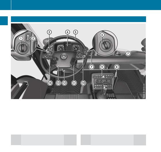
36 Cockpit
Cockpit
At a glance
|
Function |
Page |
|
|
: |
Light switch |
74 |
|
; |
Headlamp range control |
75 |
|
= |
Cruise control lever |
44 |
|
? |
Instrument cluster |
39 |
AMultifunction steering
|
wheel |
42 |
|
|
B |
Differential locks |
190 |
|
C |
Cup holder |
93 |
|
Function |
Page |
|
|
D |
Universal carrier |
94 |
|
E |
Centre console |
40 |
|
F |
Multifunction lever |
45 |
|
G |
Ignition lock |
159 |
HTo adjust the multifunction
|
steering wheel |
70 |
|
|
I |
Horn |
|
|
J |
Combination switch |
44 |
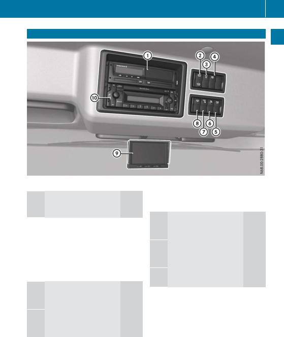
Overhead control panel 37
Overhead control panel
At a glance
:Tachograph, see the manufacturer’s operating instructions
|
; |
z Switches the front |
|
|
windscreen heating |
||
|
on/off |
90 |
|
|
= |
I Switches the lateral |
|
|
end position of wind- |
||
|
screen wipers |
||
|
on/off |
88 |
|
?Q Switches on the headlamp cleaning
AJ Switches the external lighting control
|
Function |
Page |
|
|
B |
i Switches the work- |
|
|
ing-area lamp on/off |
77 |
|
Cé Switches the auxiliary headlamps
DÀ Switching the rotating beacons or
EMonitor for front, rearview
|
and equipment cameras |
196 |
|
|
F |
CD radio |
148 |
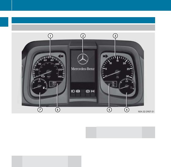
38 Instrument cluster
Instrument cluster
Displays
At a glance
|
Example: instrument cluster |
||
|
Function |
Page |
|
|
: |
Speedometer |
|
|
; |
On-board computer |
115 |
|
= |
Rev counter |
110 |
|
? |
AdBlue® level |
111 |
ATotal distance and trip dis-
i On vehicles without display A and B, scroll in the on-board computer to the Truck info menu window in the ßtour data menu (Y page 118). The menu window displays the total distance recorder, trip meter, time and outside temperature.
BClock and outside temper-
|
ature display |
112 |
|
|
C |
Fuel level |
111 |
![]()
Instrument cluster 39
Warning and indicator lamps
At a glance
|
Example: instrument cluster |
|
|
Function |
Page |
:Warning and indicator lamps in the speedometer
|
;Engine diagnostics |
113 |
|
|
ºCab tilt lock |
314 |
|
|
iDifferential lock |
190 |
|
|
WInstruction to brake at |
||
|
high engine speeds |
110 |
|
|
; |
Turn signals |
75 |
|
= |
Warning and indicator |
|
|
lamps in the rev counter |
||
|
!ABS (Anti-lock Brak- |
164 |
|
|
ing System) |
||
|
JBrake pressure |
161 |
|
Function |
Page |
|
|
ÉDiesel particle filter, |
||
|
automatic regeneration |
213 |
|
|
ÂDiesel particle filter |
||
|
malfunction |
213 |
|
|
A |
Warning and indicator |
|
|
lamps below the on- |
||
|
board computer |
||
|
KMain-beam head- |
75 |
|
|
lamps |
||
|
ÃContinuous brake |
167 |
|
|
!Parking brake |
166 |
|
|
USide lamps/dipped- |
74 |
|
|
beam headlamps |
||
?Warning and indicator lamps in the AdBlue® display
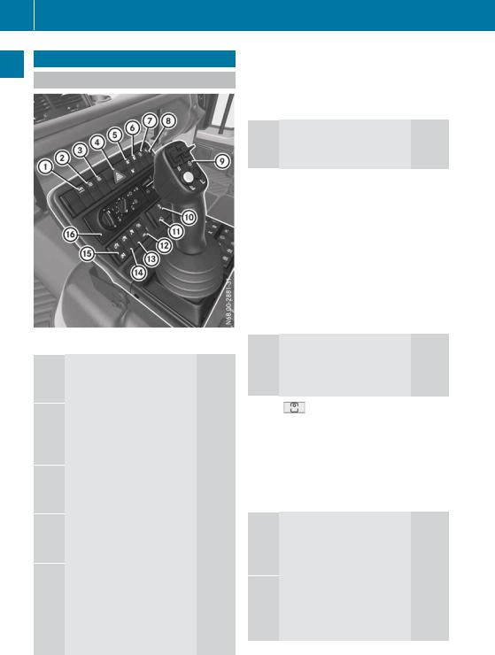
40 Centre console
Centre console
Front centre console
At a glance
:K Activates/deactivates ABS Off-road
;U Activates/deactivates transmissiondriven power take-
=T Activates/deactivates engine-driven
?£ Switches the hazard warning lamps
A÷ Tyre pressure control system: increa-
ÖTyre pressure control system: reduces
|
Function |
Page |
|
|
B |
Õ Activates/deacti- |
|
|
vates the tyre pres- |
||
|
sure control system |
186 |
|
CF Manually activates/ deactivates engine
|
speed mode |
262 |
|
|
D |
Î Activates/deacti- |
|
|
vates hydrostatic |
||
|
drive system |
198 |
|
|
E |
Operates the hydrostatic |
|
|
drive system |
198 |
|
|
Operates the hydraulic sys- |
||
|
tem |
228 |
|
|
Changes the installation |
||
|
position of the control lever |
||
|
and hydraulic system con- |
95 |
|
|
trols |
||
FL Front PTO shaft: activates/deactivates working speed
|
control |
267 |
|
|
G |
Engages/disen- |
|
|
gages the front PTO |
||
|
shaft |
267 |
|
|
H |
N Engages/disen- |
|
|
gages working gear |
182 |
|
|
O Engages/disen- |
||
|
gages crawler gear |
184 |
|
IVehicles with a trailermounted tipper platform:
|
Ö Enables/disables |
|
|
tipper function |
277 |
JVehicles with tipper platform:
|
P Enables/disables |
|
|
tipper function |
277 |
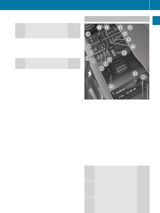
KVehicles with tipper platform, without hydraulic system:
|
Q Raises the tipper |
||
|
platform |
277 |
|
|
R Lowers the tipper |
||
|
platform |
277 |
|
LHeating/air-conditioning
Centre console 41
Rear centre console
At a glance
|
Function |
Page |
|
|
: |
Adjusts the exterior mirrors |
71 |
|
; |
É Diesel particle filter, |
|
|
starts stationary |
||
|
manual regeneration |
213 |
|
|
Ê Diesel particle filter, |
||
|
blocks regeneration |
214 |
|
|
= |
Õ Switches the equip- |
|
|
ment camera on/off |
196 |
|
|
? |
& Locks the doors |
57 |
|
% Unlocks the doors |
57 |
|
AS Vehicles with mowing door: wipes with
Bw Switches the righthand seat heating
Cw Switches the seat heating on the left-
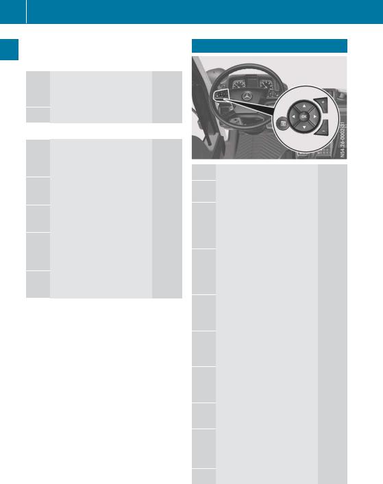
42 Multifunction steering wheel
At a glance
|
Function |
Page |
|
|
D |
Parking brake |
166 |
EFleetBoard (see the manufacturer’s operating instructions)
F Device mounting bracket
|
G |
Auxiliary heating timer |
102 |
HÏ Applies/releases the four-wheel park-
I£ Switches engine pre-
JJ Switching the 12 V
KÈ Switches radiator quick cleaning sys-
L¿ Opens/closes the
|
side windows |
60 |
|
|
M |
12 V socket |
91 |
|
N |
T Switches on the mir- |
|
|
ror heating |
72 |
|
|
U Switches off the mir- |
||
|
ror heating |
72 |
|
|
O |
24 V socket |
91 |
Multifunction steering wheel
Operating the on-board computer: 115
uSelects the next main menu/next entry in the input window, increases or resets value
tSelects the previous main menu/previous entry in the input window or decreases value
rNext menu window/next menu bar down in the input window
sPrevious menu window/ next menu bar up in the input window
9Opens and closes input window/acknowledges event window
|
Ú |
Stores/displays the favour- |
|
|
ite menu window |
||
|
W Increases the volume: |
||
|
Audio |
122 |
|
|
Telephone |
121 |
X Reduces the volume:
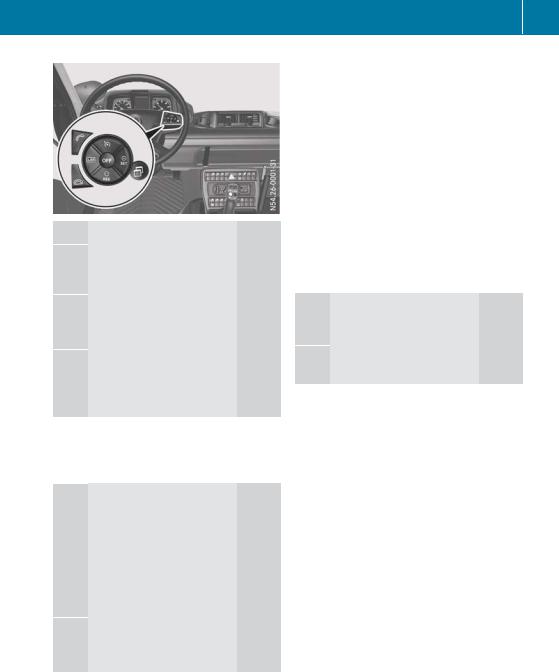
|
Function |
Page |
|
Operating the speed lim- |
|
|
iter: |
191 |
|
Operating cruise control: |
193 |
|
é Selects cruise control |
194 |
|
Switches off the working |
|
|
mode limiter |
204 |
ÑActivates and adjusts current speed/limit speed, increases the speed/limit speed
|
Speed limiter |
191 |
|
|
Cruise control |
193 |
|
|
Working mode cruise con- |
||
|
trol |
203 |
|
qActivates and calls up stored speed/limit speed, reduces set speed/limit speed
|
Speed limiter |
191 |
|
Cruise control |
193 |
|
Working mode cruise con- |
|
|
trol |
203 |
|
È Selects the speed limiter |
192 |
|
Switches on the working |
|
|
mode limiter |
204 |
|
Multifunction steering wheel |
43 |
|||
|
Function |
Page |
|||
|
o |
Deactivates the speed lim- |
|||
|
glance |
||||
|
iter |
193 |
|||
|
Deactivates cruise control |
196 |
|||
|
Switches off the working |
a |
|||
|
mode cruise control and |
||||
|
At |
||||
|
working mode limiter |
203 |
|||
|
Ù |
Input window: |
|||
|
Cruise control, adjusts the |
||||
|
speed tolerance |
195 |
|||
|
Equipment operation, |
||||
|
engine speed setting |
263 |
|||
|
Operating the telephone: |
121 |
|||
; Makes or accepts a call/ displays the Telephone menu window
= Ends/rejects an incoming call
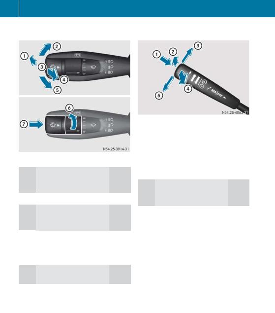
44 Cruise control lever
Combination switch |
Cruise control lever |
|||
At a glance
:Main-beam headlamps on (when dipped-beam head-
|
lamps are switched on) |
75 |
|
|
; |
Turn signal, right |
75 |
=Main-beam headlamps off (when dipped-beam head-
|
lamps are switched on) |
75 |
|
|
? |
Headlamp flasher |
75 |
|
A |
Turn signal, left |
75 |
|
B |
Windscreen wipers |
88 |
CTo wipe with washer
|
Function |
Page |
|
|
: |
Speed limiter: activating/ |
|
|
deactivating the speed lim- |
||
|
iter |
191 |
|
|
Cruise control: activat- |
||
|
ing/deactivating cruise |
193 |
|
|
control |
||
;Telligent® gearshift: gear
|
preselection (shifting |
||
|
down) |
169 |
|
|
Telligent® automatic |
||
|
gearshift: shifting down |
175 |
|
|
manually |
||
|
= |
Speed limiter: increasing |
191 |
|
set limit speed |
||
|
Cruise control: increasing |
||
|
set speed |
193 |
|
|
Telligent® gearshift: |
||
|
selecting direction of travel |
169 |
|
|
(forward) |
||
|
Telligent® automatic |
||
|
gearshift: selecting direc- |
175 |
|
|
tion of travel (forward) |
||
|
? |
Telligent® gearshift: gear |
|
|
preselection (shifting up) |
169 |
|
|
Telligent® automatic |
||
|
gearshift: shifting up man- |
175 |
|
|
ually |
||
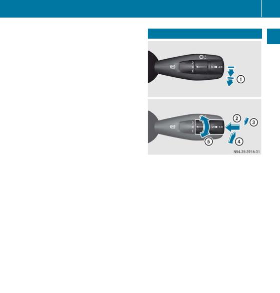
|
Function |
Page |
|
|
A |
Speed Limiter: reducing |
|
|
set limit speed |
191 |
|
|
Cruise control: decreasing |
193 |
|
|
set speed |
||
|
Telligent® gearshift: |
||
|
selecting direction of travel |
169 |
|
|
(backwards) |
||
|
Telligent® automatic |
||
|
gearshift: selecting direc- |
175 |
|
|
tion of travel (backwards) |
||
Multifunction lever 45
Multifunction lever
At a glance
|
Function |
Page |
|
|
: |
Continuous brake |
167 |
|
; |
Telligent® automatic |
|
|
gearshift: automatic gear- |
||
|
shift — drive program selec- |
||
|
tion |
177 |
|
|
d Automatic drive pro- |
||
|
gram A |
||
|
p Manual drive program M |
||
|
= |
Telligent® gearshift: gear |
|
|
preselection (shifting |
168 |
|
|
down) |
||
|
Telligent® automatic |
||
|
gearshift: shifting down |
174 |
|
|
manually |
||
|
? |
Telligent® gearshift: gear |
|
|
preselection (shifting up) |
168 |
|
|
Telligent® automatic |
||
|
gearshift: shifting up man- |
174 |
|
|
ually |
||

46 Multifunction lever
At a glance
|
Function |
Page |
|
|
A |
Telligent® gearshift: |
|
|
selecting direction of travel |
168 |
|
|
h Drive/forwards |
||
|
i Neutral |
||
|
k Reverse |
||
|
Telligent® automatic |
||
|
gearshift: selecting direc- |
174 |
|
|
tion of travel |
||
|
h Drive/forwards |
||
|
i Neutral |
||
|
k Reverse |
||

47
|
Useful information ………………………… |
48 |
|
Occupant safety ……………………………. |
48 |
|
Children in the vehicle …………………… |
51 |
|
Pets in the vehicle …………………………. |
53 |
Safety

|
48 |
Occupant safety |
||
Useful information |
|||
|
These Operating Instructions describe all the |
|||
|
models and standard and optional equipment |
|||
|
of your vehicle that were available at the time |
|||
Safety |
|||
|
of going to print. Country-specific differences |
|||
|
are possible. Bear in mind that your vehicle |
|||
|
may not be equipped with all the functions |
|||
|
described. This also applies to safety-relevant |
|||
|
systems and functions. |
|||
|
Read the information on qualified specialist |
|||
|
workshops (Y page 30). |
|||
|
Occupant safety |
|||
Restraint system introduction |
|||
|
The restraint system can reduce the risk of |
|||
|
vehicle occupants coming into contact with |
|||
|
parts of the vehicle’s interior in the event of |
|||
|
an accident. |
|||
|
The restraint system can only offer protection |
|||
|
if all vehicle occupants always: |
|||
|
Rhave the seat belt correctly fastened |
|||
|
(Y page 49) |
|||
|
Rhave the seat and head restraint adjusted |
|||
|
properly (Y page 64) |
|||
|
As the driver, you must also make sure that |
|||
|
the steering wheel is also adjusted properly. |
|||
|
Observe the information on the correct driv- |
|||
|
er’s seat position (Y page 64). |
|||
|
See «Children in the vehicle» for further infor- |
|||
|
mation on children travelling in the vehicle as |
|||
|
well as on child restraint systems |
|||
|
(Y page 51). |
|||
Important safety notes |
|||
|
G WARNING |
|||
|
If the restraint system is modified, it may no |
|||
|
longer work as intended. The restraint system |
|||
|
may then not perform its intended protective |
|||
|
function by failing in an accident or triggering |
|||
|
unexpectedly, for example. There is an |
|||
|
increased risk of injury, possibly even fatal. |
|||
Never modify parts of the restraint system. Do not attempt to modify the wiring as well as electronic components or their software.
Seat belts
Introduction
A correctly worn seat belt is the most effective means of restraining the movement of vehicle occupants in the event of a collision. This reduces the risk of vehicle occupants coming into contact with parts of the vehicle interior or being ejected from it.
If the seat belt is pulled quickly or sharply by the belt sash guide, the inertia reel locks. The belt strap cannot be pulled out any further.
Important safety notes
G WARNING
The seat belt cannot perform its intended protective function if it is not fastened correctly. Also, an improperly fastened seat belt can cause additional injuries in the event of an accident, sudden braking or abrupt changes of direction. There is an increased risk of injury, possibly even fatal.
Always make sure that all vehicle occupants are wearing their seat belt properly and are seated correctly.
G WARNING
The seat belt does not offer the intended level of protection if you have not moved the backrest to an almost vertical position. When braking or in the event of an accident, you could slide underneath the seat belt and sustain abdomen or neck injuries, for example. This poses an increased risk of injury or even fatal injury.
Adjust the seat properly before beginning your journey. Always ensure that the backrest is in an almost vertical position and that the shoulder section of your seatbelt is routed across the centre of your shoulder.
 Loading…
There’re some MERCEDES BENZ Unimog Truck Service Manuals PDF above the page.
On January 1, 1946, the first Allzwecktraktor (the name was given to the truck) rolled out of the gates of the assembly shop.
By the end of the year, it received the familiar name Unimog (from Universal-Motor-Gerät).
Until 1951, 600 Unimogs, typical for the company in dark green color, were built. They are known as the 70200 series.
But in 1951, seeing the success of small production, the giant Daimler-Benz AG corny offered the owners an amount that they could not refuse. The trucks brand came under the
control of Mercedes.
Symbols
G
WARNING
Warning notes make you aware of dangers
which could pose a threat to your health or
life, or to the health and life of others.
H
Environmental note
Environmental notes provide you with infor-
mation on environmentally aware actions or
disposal.
Notes on material damage alert you to
!
dangers that could lead to damage to your
vehicle.
These symbols indicate useful instruc-
i
tions or further information that could be
helpful to you.
X
This symbol designates an instruc-
tion you must follow.
X
Several consecutive symbols indi-
cate an instruction with several
steps.
(Y page) This symbol tells you where you
can find further information on a
topic.
Y Y
This symbol indicates a warning or
an instruction that is continued on
the next page.
Display
This text indicates a message on
the display.