Информация
- О Нас
- Скачать каталоги
Интернет-Магазин Электрооборудования Вигор-Энерго. Работаем с 2008 года. Более 100 тысяч наименований. Заказать можно на сайте по выгодной цене с доставкой по России.
Данный веб-сайт носит исключительно информационный характер и ни при каких условиях не является публичной офертой, определяемой положениями Статьи 437 (часть 2) ГК РФ.
По всем возникающим вопросам звоните по телефону +7 (351) 776-93-51 в Челябинске
ИНН 7453194460, КПП 745301001, ОГРН 1087453003329
Our Brands
Register today
- Get custom product tools and services
- Access training
- Manage support cases
- Create and manage your orders (authorized partners only)
Create account
Log in
Read more benefits
0
item count of documents is
Item count in cart is
0
My Products
My Documents
Login/Register opens in new window

Schneider Electric USA Website
Welcome to our website.
 ATV312 programming manual")
V5.1IE57
Date : 05/06/2016
Type : User guide
Languages : English
Version : 04
Document Number : BBV46385
Date : 05/06/2016
Type : User guide
Languages : English
Version : 04
Document Number : BBV46385
Download
Files
| File Name |
ATV312_programming_manual_EN_BBV46385_04
(1.8 mb)
Document title
Date
Version
Languages
Document title
Product Ranges:
Altivar 312 Variable Frequency Drives VFD,
Altivar 312 Solar


Need help?
Start here!
Find answers now. Search for a solution on your own, or connect with one of our experts.
Contact Support
Reach out to our customer care team to receive more information, technical support, assistance with complaints and more.
Where to buy?
Easily find the nearest Schneider Electric distributor in your location.
Search FAQs
Search topic-related frequently asked questions to find answers you need.
Contact Sales
Start your sales inquiry online and an expert will connect with you.
2354235 11/2008
Altivar 312
Variable speed drives for asynchronous motors
Modbus communication manual
04/2009
www.schneider-electric.com
Contents
Important Information __________________________________________________________________________________________ 4
Before you begin _____________________________________________________________________________________________ 5
Documentation structure________________________________________________________________________________________ 6
Presentation _________________________________________________________________________________________________ 7
Connection to RS485 bus ______________________________________________________________________________________ 8
Configuration of the Modbus serial port ____________________________________________________________________________ 9
Modbus protocol ____________________________________________________________________________________________ 11
Appendix: Non-standard RS485 schematics _______________________________________________________________________ 16
BBV52816 04/2009
3
4
Important Information
NOTICE
Read these instructions carefully, and look at the equipment to become familiar with the device before trying to install, operate, or maintain it. The following special messages may appear throughout this documentation or on the equipment to warn of potential hazards or to call attention to information that clarifies or simplifies a procedure.
The addition of this symbol to a Danger or Warning safety label indicates that an electrical hazard exists, which will result in personal injury if the instructions are not followed.
This is the safety alert symbol. It is used to alert you to potential personal injury hazards. Obey all safety messages that follow this symbol to avoid possible injury or death.
DANGER
DANGER indicates an imminently hazardous situation, which, if not avoided, will result in death or serious injury.
WARNING
WARNING indicates a potentially hazardous situation, which, if not avoided, can result in death, serious injury or equipment damage.
CAUTION
CAUTION indicates a potentially hazardous situation, which, if not avoided, can result in injury or equipment damage.
CAUTION
CAUTION, used without the safety alert symbol, indicates a potentially hazardous situation which, if not avoided,
can result in equipment damage.
PLEASE NOTE
The word «drive» as used in this manual refers to the controller portion of the adjustable speed drive as defined by NEC.
Electrical equipment should be installed, operated, serviced, and maintained only by qualified personnel. No responsibility is assumed by
Schneider Electric for any consequences arising out of the use of this product.
© 2009 Schneider Electric. All Rights Reserved.
BBV52816 04/2009
Before you begin
Read and understand these instructions before performing any procedure with this drive.
DANGER
HAZARD OF ELECTRIC SHOCK, EXPLOSION, OR ARC FLASH
• Read and understand this manual before installing or operating the Altivar 312 drive. Installation, adjustment, repair, and maintenance must be performed by qualified personnel.
• The user is responsible for compliance with all international and national electrical code requirements with respect to grounding of all equipment.
• Many parts of this drive, including the printed circuit boards, operate at the line voltage. DO NOT TOUCH. Use only electrically insulated tools.
• DO NOT touch unshielded components or terminal strip screw connections with voltage present.
• DO NOT short across terminals PA/+ and PC/– or across the DC bus capacitors.
• Before servicing the drive:
— Disconnect all power, including external control power that may be present.
— Place a “DO NOT TURN ON” label on all power disconnects.
— Lock all power disconnects in the open position.
— WAIT 15 MINUTES to allow the DC bus capacitors to discharge. Then follow the “Bus Voltage Measurement Procedure”, see
Installation manual, to verify that the DC voltage is less than 42 V. The drive LEDs are not indicators of the absence of DC bus voltage.
• Install and close all covers before applying power or starting and stopping the drive.
Failure to follow these instructions will result in death or serious injury.
DANGER
UNINTENDED EQUIPMENT OPERATION
• Read and understand this manual before installing or operating the Altivar 312 drive.
• Any changes made to the parameter settings must be performed by qualified personnel.
Failure to follow these instructions will result in death or serious injury.
WARNING
DAMAGED DRIVE EQUIPMENT
Do not operate or install any drive or drive accessory that appears damaged.
Failure to follow these instructions can result in death, serious injury, or equipment damage.
WARNING
LOSS OF CONTROL
• The designer of any control scheme must
— consider the potential failure modes of control paths and, for certain critical control functions,
— provide a means to achieve a safe state during and after a path failure.
Examples of critical control functions are emergency stop and overtravel stop.
• Separate or redundant control paths must be provided for critical control functions.
• System control paths may include communication links. Consideration must be given to the implications of unanticipated transmission delays or failures of the link.
a
Failure to follow these instructions can result in death, serious injury, or equipment damage.
a. For additional information, refer to NEMA ICS 1.1 (latest edition), “Safety Guidelines for the Application, Installation, and Maintenance of Solid State Control” and to
NEMA ICS 7.1 (latest edition), “Safety Standards for Construction and Guide for Selection, Installation and Operation of Adjustable-Speed Drive Systems.”
5
BBV52816 04/2009
6
Documentation structure
The following Altivar 312 technical documents are available on the Schneider Electric website ( www.schneider-electric.com
) as well as on
DVD-ROM (reference VW3A8200).
Installation manual
This manual describes how to install and wire the drive.
Programming manual
This manual describes the functions, parameters and use of the drive terminal (integrated display terminal, optional graphic display terminal and optional remote terminal).
The communication functions are not described in this manual, but in the manual for the bus or network used.
Simplified manual
This manual is a simplified version of the User manual. This manual is delivered with the drive.
Quick Start sheet
The Quick Start describes how to wire and configure the drive to start motor quickly and simply for simple applications. This document is delivered with the drive.
Communication manuals: Modbus, CANopen, …
These manuals describe the assembly, connection to the bus or network, signaling, diagnostics, and configuration of the communicationspecific parameters.
They also describe the communication protocol services.
Communication variables manual
The Communication variables manual defines the drive control processes and the drive variables which can be accessed by the communication buses: Modbus, CANopen, …
BBV52816 04/2009
Presentation
The Modbus socket on the Altivar 312 can be used for the following functions:
• Configuration
• Settings
• Control
• Monitoring
The ATV312 drive supports:
• The 2-wire RS485 physical layer
• The RTU transmission mode
This guide contains information on installation and describes the Modbus services available. The «communication variables» guide describes the operating modes, as well as the Altivar 312 variables and parameters which can be accessed via the communication bus.
BBV52816 04/2009
7
Connection to RS485 bus
Connection to ATV312
Connection accessories should be ordered separately (please consult our catalogues).
Connect the RJ45 cable connector to the ATV312 connector.
Pin out of the ATV312 RJ45 Connector
View from underneath
8
8……………………1
5
6
3
4
7
8
Pin Signal
1
CANopen signal reserved
2
CANopen signal reserved
CANopen signal reserved
D1 Modbus signal
D0 Modbus signal
Not connected
VP (1)
Common Modbus signal
(1) Supply for RS232 / RS485 converter or a remote terminal
Protection against interference
• Use the Telemecanique cable with 2 pairs of shielded twisted conductors (reference: TSXCSA100, TSXCSA200, TSXCSA500).
• Keep the Modbus cable from the power cables (30 cm minimum).
• Make any crossovers of the Modbus cable and the power cables at right-angles, if necessary.
• Connect the cable shielding to the ground of each device.
For more information, please refer to the TSX DG KBL E guide: «Electromagnetic compatibility of industrial networks and fieldbuses».
RS485 bus schematic
The RS485 standard allows variants of different characteristics:
• polarisation
• line terminator
• distribution of a reference potential
• number of slaves
• length of bus
The new Modbus specification published on the Modbus.org site in 2002 contains precise details of all these characteristics. They are also summarised in the next paragraph (Standard schematic). The new Telemecanique devices conform to this specification.
Some devices comply with earlier specifications. The two most common networks are described in the appendices:
• «Uni-Telway schematic» page
16
• «Jbus schematic» page
17
Requirements enabling different types of protocol to coexist are given in the appendix:
• «Mixed schematic» page
18
In case of coexistence of different types of protocol, see the appendix page 21.
BBV52816 04/2009
Configuration of the Modbus serial port
Communication Menu Structure
The communication parameters are part of the COM- and FLt- menus.
These parameters are accessible as follows:
Communication configuration — Parameters decription
Parameter description
Modbus Address
Add
Modbus baud rate tbr
Important: only 19.2 kbps baud rate allows to communicate with the remote display)
Modbus format tFO
Range or listed values
1 to 247
4.8 kbps
9.6 kbps
19.2 kbps
8O1: 8 bits, odd parity, 1 stop bit.
8E1: 8 bits, even parity, 1 stop bit.
8N1, 8 bits, no parity, 1 stop bit
8N2: 8 bits, no parity, 2 stop bits.
Adjustable from 0.1 to 30s Modbus time out ttO
Modbus fault mgt
SLL
(This parameter is not a communication management parameter)
No action.
Freewheel stop
Ramp stop
Fast stop»
default
1
Long name
[Modbus Address]
19.2 kbps [Modbus baud rate]
8E1
10 s
—
[8 odd 1 stop]
[8 even 1 stop]
[8 no 1 stop]
[8 no 2 stop]
[Modbus time out]
[No]
[Freewheel ]
[Ramp Stop]
[Fast Stop]
Short name @
Add
—
—
4.8
9.6
19.2
801
8E1
8n1
8n2 ttO nO
YES rNP
FSt
—
—
—
WARNING
LOSS OF CONTROL
If Modbus fault management
SLL
is set to nO, communication control will be inhibited. For safety reasons, inhibition of communication fault should only be used for adjustment or special applications purpose.
Failure to follow these instructions can result in death, serious injury, or equipment damage.
BBV52816 04/2009
9
Connection to RS485 bus
Standard schematic
The standard schematic corresponds to the Modbus specification published on the Modbus.org
site in 2002
(Modbus_over_serial_line_V1.pdf, Nov 2002) and in particular to the schematic of the 2-wire multidrop serial bus.
The ATV312 drive conforms to this specification.
Schematic diagram:
Master
R
650
Ω
0 V
T
5 V
650
Ω
D1
120
Ω
1n F
120
Ω
1n F
D0
Common
R
T
R
T
Type of trunk cable
Maximum length of bus
Maximum number of stations (without repeater)
Maximum length of tap links
Bus polarisation
Line terminator
Common polarity
Shielded cable with 1 twisted pair and at least a third conductor
1000 m at 19200 bps with the Telemecanique TSX CSA ppp
cable
32 stations, ie. 31 slaves
20 m for one tap link
40 m divided by the number of tap links on a multiple junction box
One 450 to 650
Ω
pulldown resistor at 5 V (650
Ω
recommended)
One 450 to 650 Ω pulldown resistor at the Common (650 Ω recommended)
This polarisation is recommended for the master.
One 120 Ω 0.25 W resistor in series with a 1nF 10 V capacitor
Yes (Common), connected to the protective ground at one or more points on the bus
10
BBV52816 04/2009
Modbus protocol
Configuration of the serial link
Configuration of the serial link parameters can be accessed from the Communication menu
COM-
Parameters
Address
Add
Speed tbr
Possible values
1 to 247
Terminal display
001
to
247
Format tFO
4800 bps
9600 bps
19200 bps (1)
8 data bits, odd parity, 1 stop bit
8 data bits, even parity, 1 stop bit (1)
8 data bits, no parity, 1 stop bit
8 data bits, no parity, 2 stop bits
4.8
9.6
19.2
8O1
8E1
8n1
8n2
(1) The display terminal will only work with these values.
RTU mode
The transmission mode used is RTU mode. The frame contains no message header byte, nor end of message bytes.
It is defined as follows:
Default value
1
19200 bps
8E1
Slave address
Request code Data CRC16
The data is transmitted in binary code.
CRC16: cyclical redundancy check.
The end of the frame is detected on a silence greater than or equal to 3 characters.
Principle
The Modbus protocol is a master-slave protocol.
Master
Only one device can transmit on the line at any time.
The master manages the exchanges and only it can take the initiative.
It interrogates each of the slaves in succession.
No slave can send a message unless it is invited to do so.
The master repeats the question when there is an incorrect exchange, and declares the interrogated slave absent if no response is received within a given time period.
If a slave does not understand a message, it sends an exception response to the master. The master may or may not repeat the request.
Slave j
Slave i
Direct slave-to-slave communications are not possible.
Slave k
For slave-to-slave communication, the application software must therefore be designed to interrogate a slave and send back data received to the other slave.
Two types of dialogue are possible between master and slaves:
• the master sends a request to a slave and waits for its response
• the master sends a request to all slaves without waiting for a response (broadcasting principle)
Addresses
• The drive Modbus address can be configured from 1 to 247.
• Address 0 coded in a request sent by the master is reserved for broadcasting. ATV 312 drives take account of the request, but do not respond to it.
BBV52816 04/2009
11
Modbus protocol
Modbus functions
The following table indicates which Modbus functions are managed by the Altivar 312, and specifies their limits.
The “read” and “write” functions are defined from the point of view of the master.
Code
(decimal)
3
6
16
43
Function name
Read N output words
Write one output word
Write N output words
Identification
Broadcasting
NO
YES
YES
NO
Max. value of N
29 words max.
–
27 words max.
–
Modbus standard name
Read Holding Registers
Preset Single Register
Preset Multiple Regs
Read Device Identification
Read N output words: function 3
Note: Hi = high order byte, Lo = low order byte.
This function can be used to read all ATV 312 words, both input words and output words.
Request
Slave no.
1 byte
03
1 byte
No. of first word
Hi
2 bytes
Lo
Number of words
Hi
2 bytes
Lo Lo
CRC16
2 bytes
Hi
Response
Slave no.
1 byte
03
1 byte
Number of bytes read
1 byte
First word value
Hi Lo
2 bytes
——Last word value
Hi Lo
2 bytes
Example: read 4 words W3102 to W3105 (16#0C1E to 16#0C21) in slave 2, using function 3, where:
• SFr = Switching frequency = 4 kHz (W3102 = 16#0028)
• tFr = Maximum output frequency = 60 Hz (W3103 = 16#0258)
• HSP = High speed = 50 Hz (W3104 = 16#01F4)
• LSP = Low speed = 0 Hz (W3105 = 16#0000)
Request 02 03 0C1E 0004 276C
Response 02 03
Value of:
Parameters:
08 0028
W3102
SFr
0258
W3103 tFr
01F4
W3104
HSP
0000
W3105
LSP
CRC16
Lo
2 bytes
Hi
52B0
Write one output word: function 6
Request and response (the frame format is identical)
06 Slave no.
1 byte 1 byte
Hi
Word number
Lo
2 bytes
Hi
Value of word
Lo
2 bytes
Example: write value 16#000D in word W9001 (16#2329) in slave 2 (ACC = 13 s).
Request and response 02 06 2329 000D 9270
Lo
CRC16
2 bytes
Hi
12
BBV52816 04/2009
Modbus protocol
Identification: Function 43 (16#2B)
Request
2B Slave no.
1 byte 1 byte
Type of MEI
0E
1 byte
ReadDeviceId
01
1 byte
Response
Slave no.
1 byte
2B
1 byte
Type of MEI
0E
1 byte
ReadDeviceId
01
1 byte
Object Id
00
1 byte
Lo
CRC16
2 bytes
Hi
Degree of conformity
02
1 byte
——-
——-
——-
Number of additional frames
00
1 byte
Id of object no. 1
00
1 byte
Length of object no. 1
0D
1 byte
Next object Id
00
1 byte
Value of object no. 1
“Telemecanique”
13 bytes
Number of objects
03
1 byte
——-
——-
——Id of object no. 2
01
1 byte
Length of object no. 2
0F
1 byte
Value of object no. 2
“ATV31HU09M3S232”
15 bytes
——-
——Id of object no. 3
02
1 byte
Length of object no. 3
04
1 byte
Value of object no. 3
“0201”
0 4 bytes
——-
——-
Lo
1 byte
CRC16
Hi
1 byte
The total response size equals 48 bytes
The three objects contained in the response correspond to the following objects:
• Object no
. 1:
• Object no
. 2:
• Object no
. 3:
Manufacturer name (always “Telemecanique”, ie. 13 bytes).
Device reference (ASCII string; for example: “ATV31HU09M3S232”, ie. 15 bytes).
Device version, in “MMmm” format where “MM” represents the determinant and “mm” the subdeterminant (4-byte ASCII string; for example: “0201” for version 2.1).
Note: The response to function 43 may be negative; in this case, the response located at the top of the next page is sent by the Altivar 312 rather than the response described above.
BBV52816 04/2009
13
Modbus protocol
Negative response
Slave no.
1 byte
2B + 80
AB
1 byte
Error code:
Type of MEI
0E
1 byte
Error code
00 to 02
1 byte
Lo
1 byte
CRC16
Hi
1 byte
• 16#0
0 =
• 16#0
1 =
• 16#0
2 =
No error
The “Request code” (16#2B), the “Type of MEI” (16#0E) or the “ReadDeviceId” (16#01) contained in the request is incorrect
The “Object Id” (16#00) contained in the request is incorrect
Example: Following the request from the Modbus master, slave 2 identifies itself as follows:
• Manufacturer name = “Telemecanique” (13 bytes)
• Device name = “ATV31HU09M3S232” (15 bytes)
• Device version = “0201” (4 bytes)
Request 02 2B 0E 01 00 3477
Response 02 2B 0E 01 02 00 00 03 ——-
——00 0D
——01 0F
54 45 4C 45 4D 45 43 41 4E 49 51 55 45 ——-
41 54 56 33 31 48 55 30 39 4D 33 53 32 33 32 ——-
——02 04 30 32 30 31 A80F
Write N output words: function 16 (16#10)
Request
No.
slave
1 byte
10
1 byte
No. of first word
Hi Lo
2 bytes
Number of words
Number of bytes
2 bytes 1 byte
Response
Slave no.
1 byte
10 No. of first word
Hi Lo
2 bytes
Number of words
Hi Lo
2 bytes 1 byte
Example: write values 20 and 30 in words W9001 and W9002 in slave 2
(ACC = 20 s and DEC = 30 s)
Request 02 10 2329 0002 04 0014
Value of first word
Hi Lo
2 bytes
Lo
CRC16
2 bytes
Hi
001E 517F
Response 02 10 2329 0002 8FED
——-
Lo
CRC16
Hi
2 bytes
14
BBV52816 04/2009
Modbus protocol
Exception responses
An exception response is returned by a slave when it is unable to perform the request which is addressed to it.
Format of an exception response:
Slave no.
1 byte
Response
code
1 byte
Error code
1 byte
Lo
CRC16
2 bytes
Hi
Response code: request function code + 16#80.
Error code:
1 = The function requested is not recognized by the slave
2 = The bit or word addresses indicated in the request do not exist in the slave
3 = The bit or word values indicated in the request are not permissible in the slave
4 = The slave has started to execute the request but cannot continue to process it completely
CRC16 calculation
The CRC16 is calculated on all the message bytes by applying the following method:
Initialize the CRC (16-bit register) to 16#FFFF.
Enter the first to the last byte of the message:
CRC
Enter
XOR
8 times
<byte> —> CRC
Move the CRC one bit to the right
If the output bit = 1, enter CRC XOR 16#A001—> CRC
End enter
End enter
The CRC obtained will be transmitted with the low order bytes sent first, followed by the high order ones (unlike the other data contained in
Modbus frames).
XOR = exclusive OR.
BBV52816 04/2009
15
Appendix: Non-standard RS485 schematics
Uni-Telway schematic
The Uni-Telway bus schematic has been used by Telemecanique for its drives and soft starters (ATV58, ATV28, etc).
Schematic diagram:
Master
R
4.7 k
Ω
0 V
T
5 V
4.7 k
Ω
D(B)
120
Ω
1 nF
120
Ω
1 nF
D(A)
0VL
4.7 k
Ω
0 V
5 V
4.7 k
Ω
R
T
Slave 1
4.7 k
Ω
0 V
R
T
5 V
4.7 k
Ω
Slave n
Type of trunk cable
Maximum length of bus
Maximum number of stations (without repeater)
Maximum length of tap links
Bus polarisation
Line terminator
Common polarity
Cable with 2 twisted pairs shielded in pairs
1000 m at 19200 bps
29 stations, ie. 28 slaves
• 20 m
• 40 m divided by the number of tap links on a multiple junction box
For the master and each slave:
• One 4.7 k
Ω pulldown resistor at 5 V
• One 4.7 k
Ω pulldown resistor at 0 VL
One 120
Ω 0.25 W resistor in series with a 1 nF 10 V capacitor
Yes (0 VL) and high impedance placed between 0 VL and the ground in each station
16
BBV52816 04/2009
Appendix: Non-standard RS485 schematics
Jbus schematic
Schematic diagram:
Master
R
470
Ω
0 V
T
5 V
470
Ω
L- (B/B’)
150
Ω
L+ (A/A’)
150
Ω
R
T
Slave 1
R
T
Slave n
Type of trunk cable
Maximum length of bus
Maximum number of stations (without repeater)
Maximum length of tap links
Bus polarisation
Line terminator
Common polarity
Cable with 1 shielded twisted pair
1300 m at 19200 bps
32 stations, ie. 31 slaves
3 m
One 470
Ω pulldown resistor at 5 V
One 470
Ω pulldown resistor at 0 V
This polarisation is often provided in the master.
One 150
Ω resistor
No
BBV52816 04/2009
17
Appendix: Non-standard RS485 schematics
Mixed schematic
Slaves with 4.7 k
Ω polarisation can be integrated into a standard schematic. Suitable polarisation (Rp) must be calculated.
Schematic diagram:
Master
R
T
5 V
Rp
Rp
0 V
D1
120
Ω
1 nF
120
Ω
1 nF
D0
Common
4.7 k
Ω
0 V
5 V
4.7 k
Ω
R
T
R
T
Type of trunk cable
Maximum length of bus
Maximum number of stations
(without repeater)
Maximum length of tap links
Bus polarisation
Line terminator
Common polarity
Slave 1
Shielded cable with 1 twisted pair and at least a 3
1000 m at 19200 bps
Slave n
rd
conductor
At most 32 stations ie. 31 slaves (depending on Rp and the number of 4.7 k
Ω resistors)
• 20 m for a single tap link
• 40 m divided by the number of tap links on a multiple junction box
• One pulldown resistor at 5 V (Rp)
• One pulldown resistor at the Common (Rp)
This polarisation can be provided in the master.
The value of Rp should be validated (or determined) by calculating the equivalent polarisation (Re) according to the polarisation of the master and slave stations.
The value of Re must be between 162
Ω and 650 Ω (recommended value: 650 Ω).
One 120
Ω 0.25 W resistor in series with a 1 nF 10 V capacitor
Yes (Common)
• To calculate the polarisation (Rp), all station polarisations must be deemed to be connected in parallel.
Example:
If the bus Rp polarisation is 470
Ω (installed in the master) and 2 slaves have 4700 Ω polarisation, the equivalent polarisation is:
1/Re = 1/470 + 1/4700 + 1/4700 ie. Re = 1/ (1/470 + 1/4700 + 1/4700) and therefore Re = 390
Ω.
390
Ω is greater than 162 Ω, and the schematic is correct.
For an ideal equivalent polarisation (650
Ω), Rp bus polarisation can be installed so that:
1/650 = 1/Rp + 1/4700 + 1/4700 ie. Rp = 1/(1/650 — 1/4700 — 1/4700) and therefore Rp = 587
Ω.
• If the master is fitted with a 470
Ω polarisation, it is possible to connect a maximum of 18 slaves with 4.7 kΩ polarisation.
18
BBV52816 04/2009
Appendix: Non-standard RS485 schematics
Recommendations for setting up a Modbus network using non-standard devices
1. Identify polarities D0 and D1.
They are labeled in a variety of ways according to the specification used:
Modbus
EIA/TIA-485
UNI-TELWAY
Jbus
D0
A / A’
D(A)
RD + / TD +
L +
D1
B / B’
D(B)
RD — / TD —
L —
Common
C / C’
0VL
However, certain RS485 electronic components are labeled in the opposite way to the EIA/TIA-485 standard.
It may be necessary to perform a test by connecting a master to a slave, then reversing the connection in the event of failure.
2. Check polarizations.
Study the documentation supplied with the devices to determine the polarization resistance.
If there is one, check that the value is correct (see Mixed schematic page 18
)
Polarization is not always possible. For example, in the event of the 5 V not being available in the master.
3. Select a line terminator.
In the case of polarization, select an RC line terminator (R = 120
Ω, C = 1 nF).
If polarization is not possible, select an R line terminator (R = 150
Ω).
BBV52816 04/2009
19
BBV52816
ATV312_Modbus_EN_V1.pdf
04/2009
2354235 11/2008
Altivar 312
Variable speed drives
for asynchronous motors
CANopen® communication manual
09/2009
BBV52819
www.schneider-electric.com


Contents
Important Information __________________________________________________________________________________________ 4
Before you begin______________________________________________________________________________________________ 5
Documentation structure________________________________________________________________________________________ 6
Presentation _________________________________________________________________________________________________ 7
Hardware setup CANopen
Hardware setup CANopen
Configuration _______________________________________________________________________________________________ 17
Signalling __________________________________________________________________________________________________ 18
Software setup ______________________________________________________________________________________________ 19
Software setup with PL7 and SyCon _____________________________________________________________________________ 22
Description of the services _____________________________________________________________________________________ 31
Object dictionary_____________________________________________________________________________________________ 45
®
daisy chain — option VW3A31208 __________________________________________________________ 8
®
tap — option VW3CANTAP2 ______________________________________________________________ 12
BBV52819 09/2009 3
Important Information
The addition of this symbol to a Danger or Warning safety label indicates that an electrical hazard exists, which will result in
personal injury if the instructions are not followed.
This is the safety alert symbol. It is used to alert you to potential personal injury hazards. Obey all safety messages that follow
this symbol to avoid possible injury or death.
NOTICE
Read these instructions carefully, and look at the equipment to become familiar with the device before trying to install, operate, or maintain
it. The following special messages may appear throughout this documentation or on the equipment to warn of potential hazards or to call
attention to information that clarifies or simplifies a procedure.
DANGER
DANGER indicates an imminently hazardous situation, which, if not avoided, will result in death or serious injury.
WARNING
WARNING indicates a potentially hazardous situation, which, if not avoided, can result in death, serious injury or
equipment damage.
CAUTION
CAUTION indicates a potentially hazardous situation, which, if not avoided, can result in injury or equipment
damage.
CAUTION
CAUTION, used without the safety alert symbol, indicates a potentially hazardous situation which, if not avoided,
can result in equipment damage.
PLEASE NOTE
The word «drive» as used in this manual refers to the controller portion of the adjustable speed drive as defined by NEC.
Electrical equipment should be installed, operated, serviced, and maintained only by qualified personnel. No responsibility is assumed by
Schneider Electric for any consequences arising out of the use of this product.
© 2009 Schneider Electric. All Rights Reserved.
4 BBV52819 09/2009
Before you begin
Read and understand these instructions before performing any procedure with this drive.
DANGER
HAZARD OF ELECTRIC SHOCK, EXPLOSION, OR ARC FLASH
• Read and understand this manual before installing or operating the Altivar 312 drive. Installation, adjustment, repair, and
maintenance must be performed by qualified personnel.
• The user is responsible for compliance with all international and national electrical code requirements with respect to grounding of
all equipment.
• Many parts of this drive, including the printed circuit boards, operate at the line voltage. DO NOT TOUCH. Use only electrically
insulated tools.
• DO NOT touch unshielded components or terminal strip screw connections with voltage present.
• DO NOT short across terminals PA/+ and PC/– or across the DC bus capacitors.
• Before servicing the drive:
— Disconnect all power, including external control power that may be present.
— Place a “DO NOT TURN ON” label on all power disconnects.
— Lock all power disconnects in the open position.
— WAIT 15 MINUTES to allow the DC bus capacitors to discharge.
— Measure the voltage of the DC bus between the PA/+ and PC/– terminals to ensure that the voltage is less than 42 Vdc.
— If the DC bus capacitors do not discharge completely, contact your local Schneider Electric representative. Do not repair or
operate the drive
• Install and close all covers before applying power or starting and stopping the drive.
Failure to follow these instructions will result in death or serious injury.
DANGER
UNINTENDED EQUIPMENT OPERATION
• Read and understand this manual before installing or operating the Altivar 312 drive.
• Any changes made to the parameter settings must be performed by qualified personnel.
Failure to follow these instructions will result in death or serious injury.
WARNING
DAMAGED DRIVE EQUIPMENT
Do not operate or install any drive or drive accessory that appears damaged.
Failure to follow these instructions can result in death, serious injury, or equipment damage.
WARNING
LOSS OF CONTROL
• The designer of any control scheme must
— consider the potential failure modes of control paths and, for certain critical control functions,
— provide a means to achieve a safe state during and after a path failure.
Examples of critical control functions are emergency stop and overtravel stop.
• Separate or redundant control paths must be provided for critical control functions.
• System control paths may include communication links. Consideration must be given to the implications of unanticipated
transmission delays or failures of the link.
a
Failure to follow these instructions can result in death, serious injury, or equipment damage.
a. For additional information, refer to NEMA ICS 1.1 (latest edition), “Safety Guidelines for the Application, Installation, and Maintenance of Solid State Control” and to
NEMA ICS 7.1 (latest edition), “Safety Standards for Construction and Guide for Selection, Installation and Operation of Adjustable-Speed Drive Systems.”
BBV52819 09/2009 5

Documentation structure
The following Altivar 312 technical documents are available on the Schneider Electric website (www.schneider-electric.com) as well as on
DVD-ROM (reference VW3A8200).
Installation manual
This manual describes how to install and wire the drive.
Programming manual
This manual describes the functions, parameters and use of the drive terminal (integrated display terminal, optional graphic display terminal
and optional remote terminal).
The communication functions are not described in this manual, but in the manual for the bus or network used.
Simplified manual
This manual is a simplified version of the User manual. This manual is delivered with the drive.
Quick Start sheet
The Quick Start describes how to wire and configure the drive to start motor quickly and simply for simple applications. This document is
delivered with the drive.
Communication manuals: Modbus and CANopen
These manuals describe the assembly, connection to the bus or network, signaling, diagnostics, and configuration of the communicationspecific parameters.
They also describe the protocol communication services.
®
Communication variables guide
This manual defines the drive control processes and the drive variables which can be accessed by the communication buses: Modbus,
CANopen
®
, …
6 BBV52819 09/2009

Presentation
The CANopen® socket on the Altivar 312 can be used for the following functions:
• Configuration
• Settings
• Control
• Monitoring
This guide contains information on installation and describes the CANopen
describes the operating modes, as well as the Altivar 312 variables and parameters which can be accessed via the communication bus.
®
services available. The «communication variables» guide
BBV52819 09/2009 7
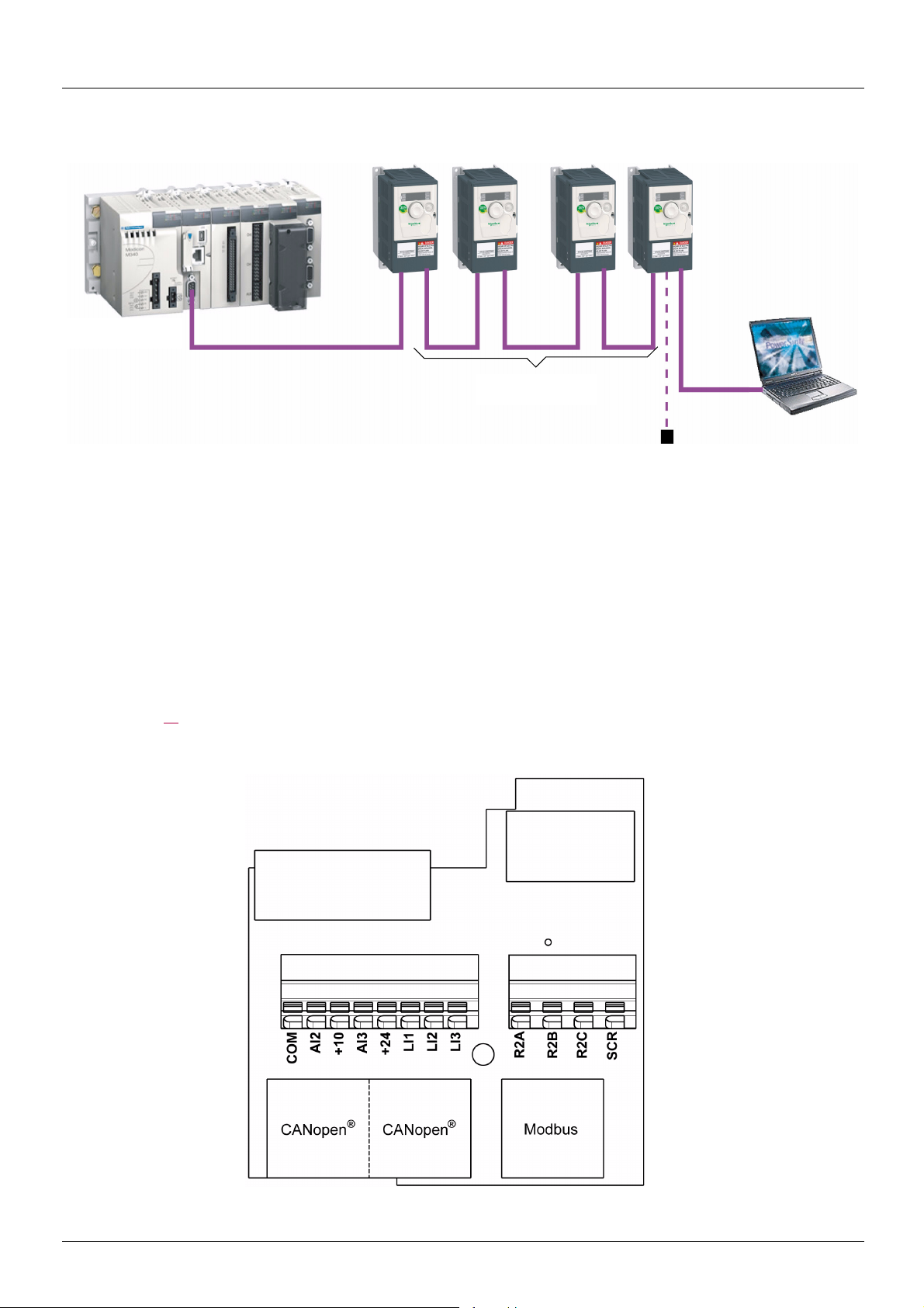
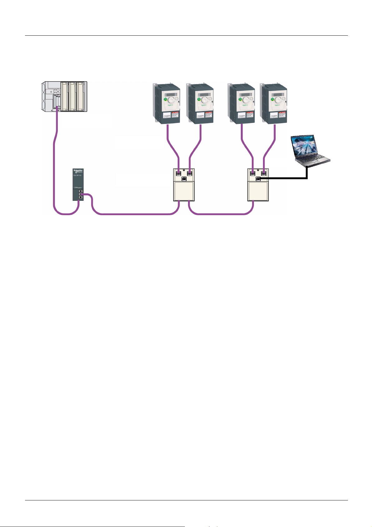
Hardware setup CANopen® daisy chain — option VW3A31208
PowerSuite
or SoMove
Line Termination
TCS CAR013M120
Modbus
Master PLC
M340 CANopen
®
ATV 312 drop cord
VW3 CAN CA RR
p
The following diagram shows an example of four ATV 312, with each one a CANopen® daisy chain module inside, and connected to M340.
®
ATV312 CANopen
• Two RJ45 connectors allow the creation of a CANopen
cord is a cable equipped with 2 RJ45 connectors. Two lengths are available: 0.3 m (0.98 ft), reference: VW3 CAN CA RR 03 and
1 m (3.28 ft), reference: VW3 CAN CA RR1.
• A third RJ45 connector to connect the ATV312 with the commissioning tools like : PowerSuite, SoMove, Bluetooth™ adaptor, Simpleloader and Multi-loader, or to connect Modbus devices (PLC, HMI, etc…).
daisychain option card (reference: VW3 A31208, supplied separately) provides:
®
network by using cables equipped with RJ45: ATV 312 CANopen® drop
The network termination is done by inserting on the last available RJ45 port of the last device on the network a line termination (reference
TCS CAR013M120). This line termination is fitted with a RJ45 to be directly inserted on the module.
As the VW3 A31208 replaces the base terminal card of the ATV312, it is also equipped with digital and analog IOs.
Note: maximum bus length are divided by 2 when an Altivar 312 is placed on a CANopen
See values page 17
.
®
bus with CANopen® daisychain VW3A31208.
Presentation
8 BBV52819 09/2009
Hardware setup CANopen® daisy chain — option VW3A31208
Receipt
• Check that the card catalog number marked on the label is the same as that on the delivery note corresponding to the purchase order.
• Remove the option card from its packaging and check that it has not been damaged in transit.
Installing the card in the drive
DANGER
UNINTENDED EQUIPMENT OPERATION
• Do not plug or unplug the terminal board while drive is powered.
• Check the tightening of the fixing screw after any manipulation on the terminal board.
Failure to follow these instructions will result in death or serious injury.
DANGER
HAZARD OF ELECTRIC SHOCK, EXPLOSION, OR ARC FLASH
Do not touch the terminal board before :
• removing power on the drive,
• removing any voltage on input and output terminals.
Failure to follow these instructions will result in death or serious injury.
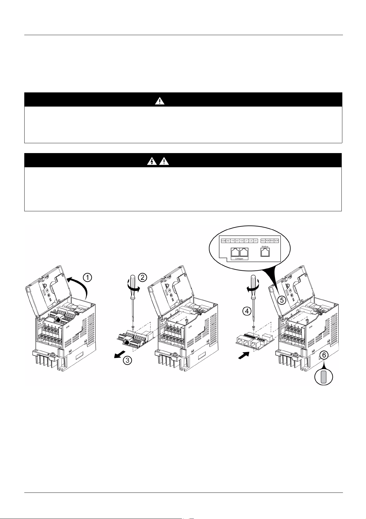
Install the CANopen® daisy chain card in ATV312 as follows:.
1. Open the ATV312 front cover.
2. Remove the terminal board fixing screw and take off the ATV312 standard terminal board.
(Be careful not to lose the terminal board fixing screw when removed since it may be used again.)
This step does not apply if you are using an ATV312…. B (product without standard IO terminal).
3. Perform wiring before installing CANopen
4. Install the CANopen
(M3 tapping screw tightening torque: 0.7 to 0.8Nm).
5. Stick the new cabling label on the reverse side of the ATV312 front cover.
6. Stick the CANopen® daisy chain card nameplate near the ATV312 nameplate. (Be careful not to cover slits on the ATV312 enclosure)
Note: To install or remove the terminal board, make it slide in or out in parallel with board to avoid mechanical stress on the board.
BBV52819 09/2009 9
®
daisy chain card and secure it with the board fixing screw
®
daisy chain card.
Hardware setup CANopen® daisy chain — option VW3A31208
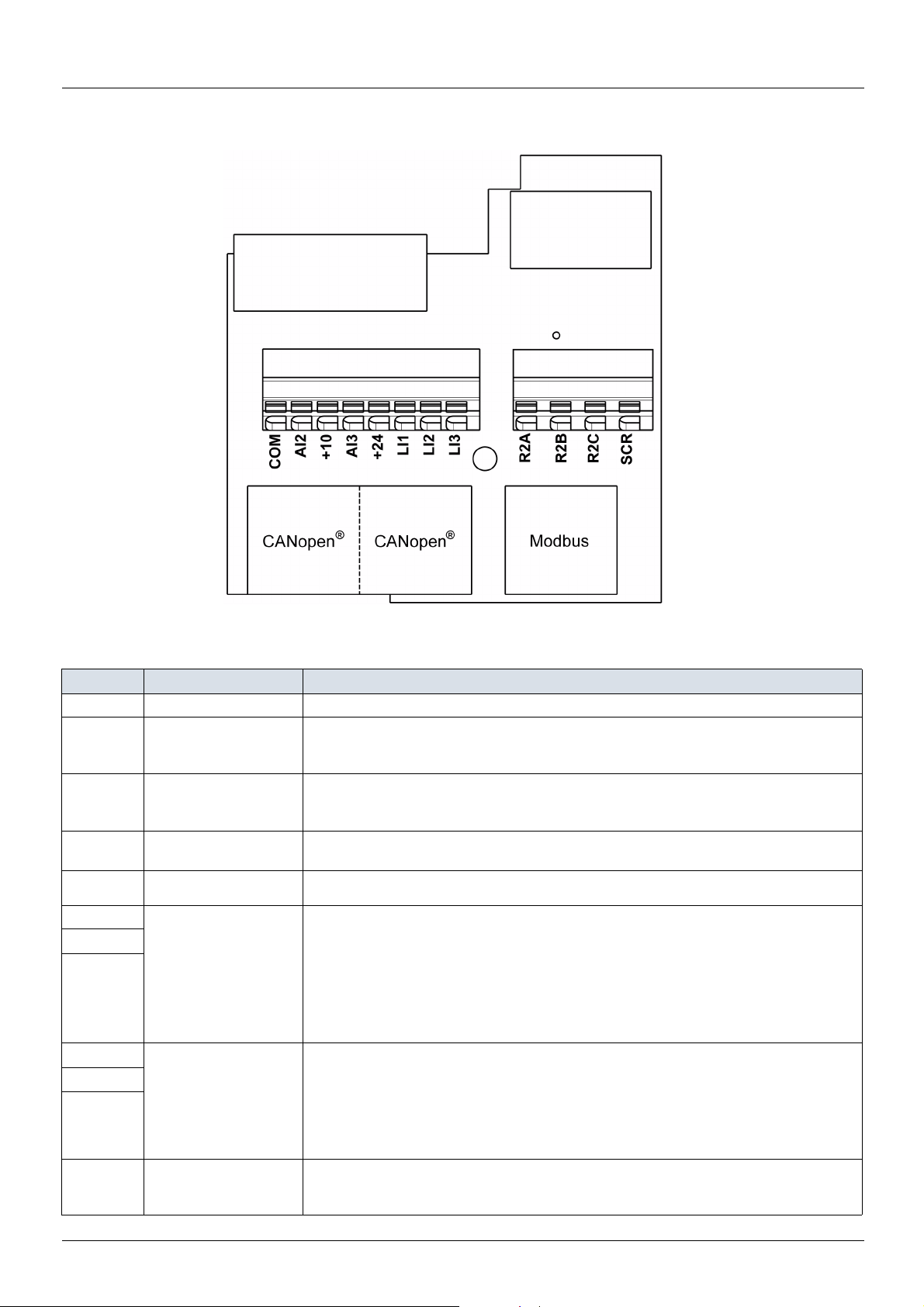
Description of the terminals
Control terminals characteristics
Terminal Function Electrical characteristics
COM Analog I/O common 0 V
Analog bipolar voltage input ±10 V:
AI2 Analog voltage input
Power supply for the
10 V
AI3 Analog current input
24 V Logic input power supply
LI1
LI2
LI3
R2A
R2B
R2C
SCR (Screen)
reference potentiometer
(2.2 to 10 k
Logic inputs
Configurable relay
outputs 1 relay logic
output, one “N/C” contact
and one “N/O” contact
with common point.
Ω)
• impedance 30 k
• maximum safe voltage 30 V
+10 V (+ 8% — 0):
• 10 mA max
• protected against short-circuits and overloads
Analog current input X-Y mA by programming X and Y from 0 to 20 mA:
impedance 250
• + 24 V protected against short-circuits and overloads, min 19 V, max 30 V
• Maximum customer current available 100 mA
Programmable logic inputs:
• Impedance 3.5 k
• + 24 V internal or 24 V external power supply (min. 19 V, max. 30 V)
• Max. current: 100 mA
• Max. sampling time: 4 ms
Source position: Positive logic State 0 if < 5 V or logic input not wired, state 1 if > 11 V
Sink position: Negative logic State 0 if > 19 V or logic input not wired, state 1 if < 13 V
CLI position: Connection to PLC output
• Minimum switching capacity: 10 mA for 5 Vdc
• Maximum switching capacity on resistive load (cos ϕ = 1 and L/R= 0 ms).
5 A for 250 Vac and 30 Vdc
• Maximum switching capacity on inductive load (cos ϕ = 0.4 and L/R = 7 ms):
2 A for 250 Vac and 30 Vdc
• Sampling time 8 ms
• Service life: 100,000 operations at maximum switching power
CANopen
This terminal is not connected to other circuits in this board.
Ground this terminal in a location separated from the ground of power line.
®
Ω
Ω
Ω
communication shield terminal.
10 BBV52819 09/2009
Hardware setup CANopen® daisy chain — option VW3A31208
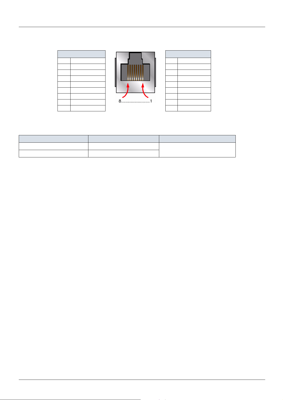
CANopen® and Modbus connectors
CANopen
Pin RJ 45 Signal Pin RJ 45 Signal
1 CAN_H 1 Not connected
2 CAN_L 2 Not connected
3 CAN_GND 3 Not connected
4 Not connected 4 D1
5 Not connected 5 D0
6 Not connected 6 Not connected
7 Not connected 7 VP (1)
8 Not connected 8 Common
®
Modbus
(1) Reserved for RS232/RS485 converter
Wire sizes
ATV312 Control terminals Applicable wire size mm² (AWG) (2) Tightening torque N·m (lb.in) (3)
R2A, R2B, R2C 0.75 to 1 (18 to 16) 0.5 to 0.6 (4.4 to 5.3)
Other terminals 0.14 to 0.5 (26 to 20)
(2)The value in bold corresponds to the minimum wire gauge to permit secureness.
(3)Recommended to maximum value.
BBV52819 09/2009 11
Hardware setup CANopen® tap — option VW3CANTAP2
PowerSuite
CANopen®
trunk cable
CANopen
®
trunk cable
ATV 312 CANopen®
tap VW3 CAN TAP 2
ATV 312 drop cord
VW3 CAN CA RR
p
Master PLC
+ TSX CPP 110
Modbus
Legacy CANopen® wiring solution for ATV 312
The following diagram shows an example of four ATV 312, connected to a master PLC Premium with a CANopen® master PCMCIA card
(TSX CPP 110).
Various accessories are available from the catalog to facilitate the connection of these devices.
ATV 312 CANopen
screw terminals embedded connectors. Two RJ45 connectors allow the connection of two Altivar 312 by ATV 312 CANopen
®
tap is a passive tap (reference: VW3CANTAP2) It can be connected on a CANopen® trunk cable, using the two 5-
®
drop cords.
One RJ45 connector is designed to interface these two Altivar 312 with PowerSuite (Commissioning software tool for PC or Pocket PC).
If only one ATV 312 is connected on the tap it should be on the connector labelled «ATV1». If two ATV 312 are connected, PowerSuite can
access the two drives in multidrop mode. The Modbus address of each drive must be different.
A remote terminal (VW3A31101) can also be connected to the «PowerSuite» connector, but in this case, only one ATV 312 drive can be
connected to the CANopen
ATV 312 CANopen
®
tap (on the plug labelled «ATV1»).
®
drop cord is a cable equipped with 2 RJ45 connectors. Two lengths are available: 0.3 m (0.98 ft), reference:
VW3CANCARR03) and 1 m (3.28 ft), reference: VW3CANCARR1.
Note: Only a 0.3 m (11.8 in.) drop cord can be used in a CANopen
®
network at a speed of 1 Mbits/s.
12 BBV52819 09/2009
Hardware setup CANopen® tap — option VW3CANTAP2
1
ATV1 ATV2
PowerSuite
S1 S2
S3
ON
S4 S5
OFF
23
4
2
4
7
9
8
10
3
5
7
6
9
8
11
10
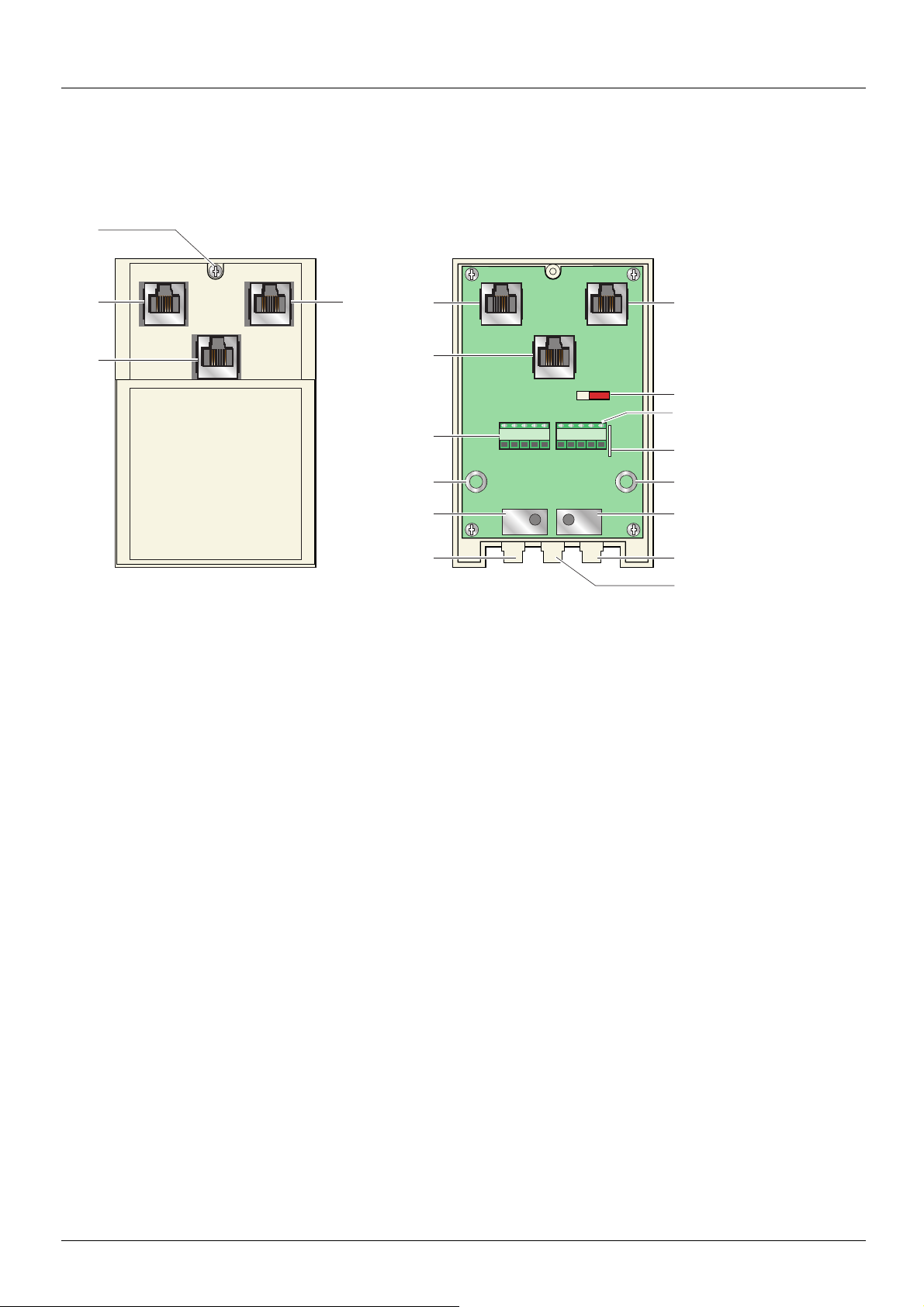
Description of the ATV 312 CANopen® tap
External view Internal view
1. Cover screw.
2. «ATV1» female RJ45 connector where the first Altivar 312 drive must be connected.
3. «ATV2» female RJ45 connector where the second, (if any), Altivar 312 drive must be connected. Do not use if a remote terminal is
connected to the «PowerSuite» connector.
4. «PowerSuite» female RJ45 connector, where PowerSuite (PC or Pocket PC) or a remote terminal can be connected.
5. Switch used to connect (ON) or disconnect (OFF) the internal line termination (120 Ω).
6. Lug for connecting the green/yellow grounding wire.
7. CANopen
8. Holes for Ø 4 screws used to mount the tap on a plate or panel, 60 mm (2.36 in.) mounting distance.
9. Ground plate for the trunk cable shield.
10. Openings for the CANopen
11. Opening for the green/yellow grounding wire.
®
terminal blocks, labelled S4 and S5 on the circuit board for wiring of the trunk cable.
®
trunk cable.
BBV52819 09/2009 13
Hardware setup CANopen® tap — option VW3CANTAP2
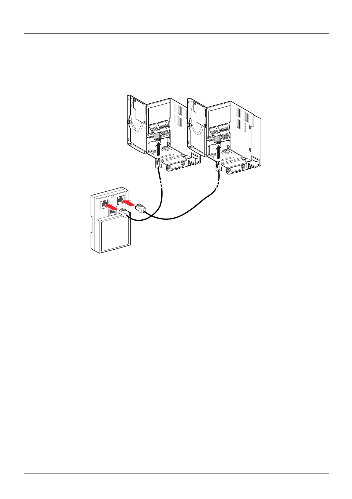
Connecting the drive to the ATV 312 CANopen® tap
Connect the cord with 2 RJ45 connectors (VW3 CAN CA RR 03 or VW3 CAN CA RR 1) to the RJ45 connector of the drive and to the «ATV1»
or «ATV2» female RJ45 connector located on the ATV 312 CANopen
If only one Altivar 312 is connected to the ATV 312 CANopen
®
tap (VW3 CAN TAP 2).
®
tap the «ATV1» connector must be used.
14 BBV52819 09/2009
Hardware setup CANopen® tap — option VW3CANTAP2
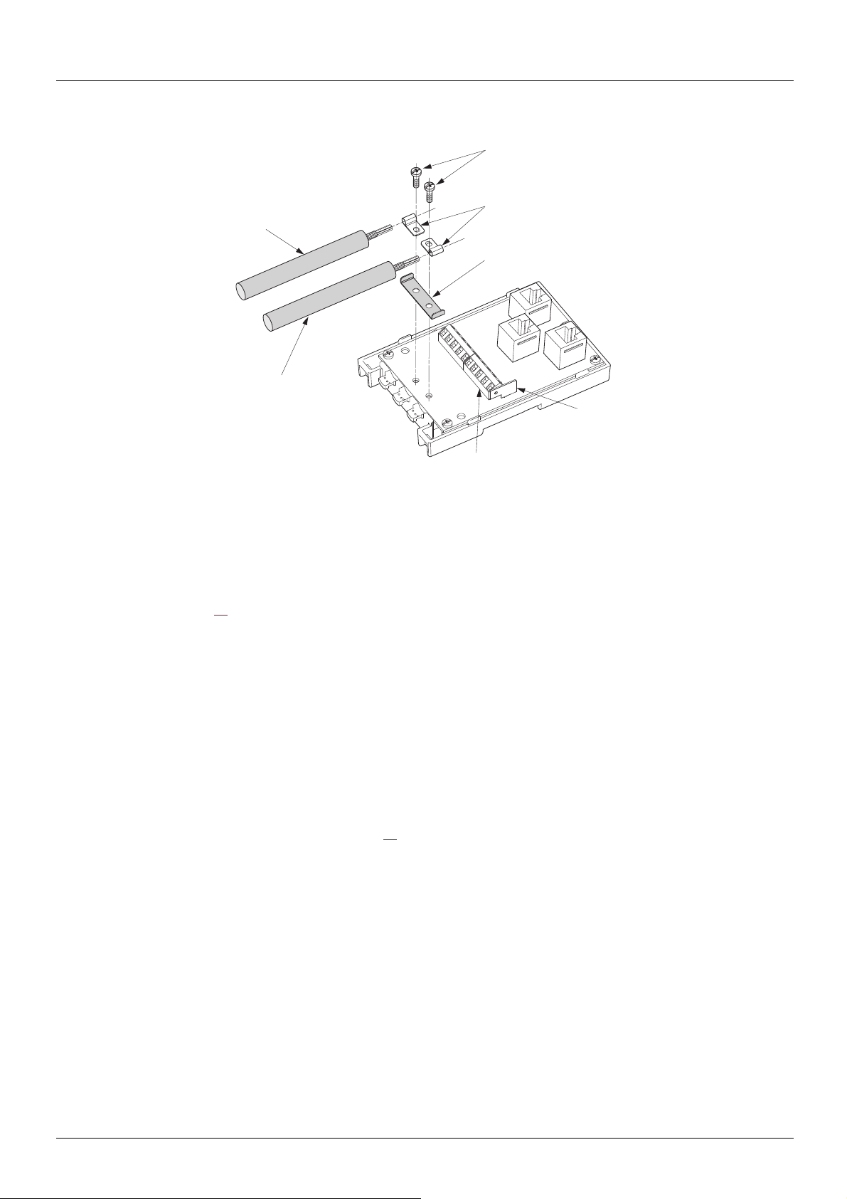
Setup of the CANopen® tap
Tools required:
• 2.5 mm flat screwdriver.
Procedure:
Note: the numbers shown below correspond to the numbers in the tap description.
• Unscrew screw 1 page 13
• Attach the tap base to its support:
— either to an AM1-DP200 or AM1-DE 200 DIN rail,
— or to a plate,
— or panel using 2 M4 screws at least 20 mm (0.8 in.) long.
• Prepare trunk cables 20 and 21, as shown on the following pages.
• Position grounding clamps 22 on the cables.
• Position ground connection 23.
• Connect the trunk cables to terminal blocks 7, as shown on the following pages. Use a 2.5 mm flat screwdriver. Thread torque on
terminal block screw
• Screw down the grounding clamps and connections using screws 19.
• Connect the green/yellow grounding wire to the connection lug 6.
• Immobilise the cables using nylon clamps.
• Position micro-switch to ON if line termination is required.
• Break the tabs on the cover so that the cables can pass through.
• Replace cover and fasten it in place with screw 1 page 13
. Open cover.
y 0.25 N·m (2.21 lb.in).
.
BBV52819 09/2009 15
 Loading…