
ОАО «Ульяновский автомобильный завод»
Автомобили
УАЗ-315195, УАЗ-315148
и их модификации
Руководство по эксплуатации
РЭ 05808600.133-2012
2012
ПАРАДАВТО
Карта сайта
Форма обратной связи
ООО «ПарадАвто», 220024, Республика Беларусь, г. Минск, ул. Стебенева, 20В
Наш рейтинг: 4.5 из 5 ★★★★★ на основании 120 отзывов
Вся представленная на сайте информация, касающаяся стоимости и технических характеристик автомобилей, условий сервисного обслуживания носит информационный характер и не является публичной офертой. Для получения подробной информации просьба обращаться к ближайшему официальному дилеру ООО «УАЗ». Опубликованная на данном сайте информация может быть изменена в любое время без предварительного уведомления.
- Руководства по ремонту
- Руководство по ремонту УАЗ 31519 (Хантер) 2003 г.в.
Руководство по ремонту Уаз Хантер 31516
Общая информация об автомобиле.
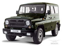
УАЗ Хантер (УАЗ-315195) — полноприводный легковой автомобиль повышенной проходимости (внедорожник) для эксплуатации на дорогах всех категорий, а также по пересечённой местности.
УАЗ «Хантер» представляет собой дальнейшее развитие второго поколения ульяновских внедорожников УАЗ-469 и УАЗ-3151. В базовой версии автомобиль оснащён закрытым пятидверным кузовом с металлическим верхом, но в семействе предусмотрена и версия с кузовом универсал-фаэтон со складываемым матерчатым верхом на съёмных дугах.
Серийно выпускается Ульяновским автозаводом с декабря 2003 года.
Автомобили семейства UAZ Hunter — легковые, повышенной проходимости, рамной конструкции, оснащены кузовом с жесткой крышей или со съемным мягким верхом, предназначены для перевозки пассажиров и грузов по всем видам дорог.
В зависимости от комплектации на автомобили UAZ Hunter устанавливают бензиновые карбюраторные двигатели мод. УМЗ-4218.10 и инжекторные двигатели мод. ЗМЗ-409, а также дизельные двигатели ЗМЗ-5143.10.
Трансмиссия выполнена по схеме постоянного заднего привода с возможностью подключения переднего привода и оснащена демультипликатором. Передняя и задняя подвески автомобиля зависимые. Передняя подвеска рычажно-пружинная со стабилизатором поперечной устойчивости, задняя — рессорная на двух продольных полуэллиптических малолистовых рессорах. Рулевое управление типа винт-шариковая гайка-сектор, оснащено гидроусилителем. Тормозные механизмы передних колес дисковые, задних — барабанные. Стояночный тормоз активируется отдельным барабанным механизмом, расположенным за раздаточной коробкой.
↓ Комментарии ↓
1. Устройство автомобиля
1.0 Устройство автомобиля
1.1 Общие сведения об автомобиле
1.2 Паспортные данные
1.3 Ключи автомобиля
1.4 Панель приборов и органы управления
1.5 Отопление и вентиляция салона
1.6 Двери
1.7. Сиденья
1.8 Зеркала заднего вида
1.9 Освещение салона
2. Рекомендации по эксплуатации
2.0 Рекомендации по эксплуатации
2.1. Правила техники безопасности и рекомендации
2.2 Рекомендации по безопасности движения
2.3. Что нужно иметь в автомобиле
2.4 Эксплуатация автомобиля в гарантийный период
2.5 Обкатка автомобиля
2.6. Подготовка автомобиля к выезду
2.7 Заправка автомобиля топливом
2.8 Пользование домкратом
2.9 Буксировка автомобиля
3. Неисправности в пути
3.0 Неисправности в пути
3.1. Двигатель не заводится
3.2 Неисправности системы впрыска топлива
3.3. Перебои в работе двигателя
3.4. Автомобиль движется рывками
3.5 Автомобиль плохо разгоняется
3.6 Двигатель заглох во время движения
3.7. Упало давление масла
3.8. Перегрев двигателя
3.9. Аккумуляторная батарея не подзаряжается
3.11. Появились посторонние стуки
3.12. Проблемы с тормозами
3.13. Прокол колеса
4. Техническое обслуживание
4.0 Техническое обслуживание
4.1. Общие положения
4.2. Ежедневное обслуживание (ЕО)
4.3. Первое техническое обслуживание (ТО-1)
4.4. Второе техническое обслуживание (ТО-2)
4.5. Особенности первого технического обслуживания (ТО-1) автомобилей с дизельным двигателем
4.6. Особенности второго технического обслуживания (ТО-2) автомобилей с дизельным двигателем
5. Двигатель
5.0 Двигатель
5.1 Особенности конструкции
5.2 Возможные неисправности двигателя, их причины и способы устранения
5.3 Полезные советы
5.4 Проверка компрессии в цилиндрах
5.5 Снятие и установка брызговиков двигателя
5.6. Замена опор подвески силового агрегата
5.7 Замена ремня привода генератора и водяного насоса
5.8 Установка поршня первого цилиндра в положение ВМТ такта сжатия
5.9 Замена цепей и шестерен газораспределительного механизма
5.13. Замена деталей уплотнения двигателя
5.14. Головка блока цилиндров двигателя
5.16. Ремонт двигателя
5.17. Cистема смазки двигателя
5.18. Система охлаждения двигателя
5.19. Система выпуска отработавших газов
5.20. Система питания
5.21. Система улавливания паров топлива
5.22. Особенности конструкции дизельного двигателя
6. Трансмиссия
6.0 Трансмиссия
6.1. Сцепление
6.2. Коробка передач
6.3. Раздаточная коробка
6.4. Карданная передача
6.5. Передний мост
6.6. Задний мост
7. Ходовая часть
7.0 Ходовая часть
7.1. Передняя подвеска
7.2. Задняя подвеска
8. Рулевое управление
8.0 Рулевое управление
8.1 Особенности конструкции
8.2 Возможные неисправности рулевого управления, их причины и способы устранения
8.3. Рулевая колонка
8.4. Рулевая трапеция
8.5. Рулевой механизм
9. Тормозная система
9.0 Тормозная система
9.1 Особенности конструкции
9.2 Возможные неисправности тормозной системы, их причины и способы устранения
9.3 Прокачка гидропривода тормозной системы
9.4 Проверка и регулировка свободного хода педали тормоза
9.5. Главный тормозной цилиндр
9.6 Замена вакуумного усилителя тормозов
9.7. Замена шлангов и трубопроводов гидропривода тормозов
9.8. Тормозные механизмы передних колес
9.9. Тормозные механизмы задних колес
9.10. Регулятор тормозных сил в гидроприводе задних тормозов
9.11. Стояночный тормоз
10. Электрооборудование
10.0 Электрооборудование
10.1 Особенности конструкции
10.2. Аккумуляторная батарея
10.3. Монтажные блоки
10.4. Генератор
10.5. Стартер
10.6. Выключатель (замок) зажигания
10.7. Электронная система управления бензиновым двигателем (система впрыска топлива)
10.8. Система зажигания инжекторных двигателей
10.9. Электронная система управления дизельным двигателем (система впрыска топлива)
10.10. Освещение, световая и звуковая сигнализация
10.11. Очиститель ветрового стекла
10.12. Бачок омывателя ветрового стекла
10.13. Очиститель стекла двери задка
10.14. Бачок омывателя стекла двери задка
10.15. Электродвигатель вентилятора системы отопления и вентиляции салона
10.16. Прикуриватель
10.17. Комбинация приборов
10.18. Спидометр
10.19. Замена датчиков и выключателей
11. Кузов
11.0 Кузов
11.1 Особенности конструкции
11.2. Снятие и установка бамперов
11.3. Снятие и установка подкрылков и брызговиков колес
11.4 Снятие и установка передних крыльев
11.5 Снятие и установка облицовки радиатора
11.6 Снятие и установка накладки облицовки радиатора
11.7 Снятие и установка брызговиков моторного отсека
11.8 Снятие и установка крышек люка пола
11.9 Снятие и установка полки аккумуляторной батареи
11.10. Капот
11.11. Боковые двери
11.12. Дверь задка
11.14. Ветровое окно
11.15. Крышки люков наливных труб топливных баков
11.16. Сиденья
11.17. Зеркала
11.18. Арматура салона
11.19. Панель приборов
11.20. Отопитель
11.21. Уход за кузовом
12. Советы начинающему автомеханику
12.0 Советы начинающему автомеханику
12.1. Техника безопасности при проведении ремонтных работ
12.2. Инструменты
12.3 Перед началом работы
12.4. Восстановление резьбовых соединений
12.5 Советы по кузовному ремонту
13. Покупка запасных частей
13.0 Покупка запасных частей
13.1 Моторное масло
13.2 Пластичные смазки
13.3 Охлаждающие жидкости
13.4 Тормозная жидкость
13.5 Топливный фильтр тонкой очистки
13.6 Воздушный фильтр
13.7 Масляный фильтр системы смазки двигателя
14. Поездка на СТО
14.0 Поездка на СТО
15. Зимняя эксплуатация автомобиля
15.0 Зимняя эксплуатация автомобиля
15.1 Как подготовить автомобиль к зиме
15.2 Рекомендации по пуску двигателя в сильный мороз
15.3 Что полезно купить к зиме
15.4 Полезные зимние советы
16. Подготовка к техосмотру
16.0 Подготовка к техосмотру
16.1 Рекомендации
16.2 Перечень неисправностей и условий, при которых запрещается эксплуатация транспортных средств
16.3 Изменения к государственным стандартам, регламентирующим предельно допустимое содержание вредных веществ в отработавших газах автотранспортных средств
17. Приложения
17.0 Приложения
17.1 Приложение 1. Моменты затяжки резьбовых соединений
17.2 Приложение 2. Температурный диапазон применяемости моторных масел
17.3 Приложение 3. Горюче-смазочные материалы и эксплуатационные жидкости
17.4 Приложение 4. Лампы, применяемые на автомобиле
17.5 Приложение 5. Специальные инструменты и приспособления
18. Схемы электрооборудования
18.0 Схемы электрооборудования
18.1 Схема 1. Соединения системы управления двигателем мод. ЗМЗ-5143.10
18.2 Схема 2. Соединения системы управления двигателем мод. ЗМЗ-409 (Евро-2)
18.3 Схема 3. Соединения системы управления двигателем мод. ЗМЗ-409 (Евро-0)
18.4 Схема 4. Электрооборудование автомобилей мод. 31519-095, 31519-195
18.5 Схема 5. Электрооборудование автомобилей мод. 315195-025, 315195-125
18.6 Схема 6. Электрооборудование автомобилей мод. 315195-023, 315195-123
Решил поделиться доступом к моим архивам на Облаке Mail.ru.
Много файлов применительно именно к УАЗ 315148 с дизельным ЗМЗ-514.
Руководства по ТОиР, ТЭ, каталоги деталей УАЗ и ЗМЗ-514, Webasto…
cloud.mail.ru/public/77iA/rsszA62by
Электросхемы УАЗа (найденные в интернете и мои доработанные):
cloud.mail.ru/public/95q2/Zd9d5A9Wb
Электросхемы и просто информация по лебедкам
cloud.mail.ru/public/yYDG/SR6sBya6m
Всем удачи!
- Manuals
- Brands
- UAZ Manuals
- Automobile
- HUNTER 315195
- Operating manual
-
Contents
-
Table of Contents
-
Bookmarks
Quick Links
Ulyanovsk Automobile Plant PJSC
Motor Vehicles
UAZ-315195 and UAZ-315148
and Versions Thereof
Operating Manual
RE 05808600.133-2012
3rd Edition
2016
Related Manuals for UAZ HUNTER 315195
Summary of Contents for UAZ HUNTER 315195
-
Page 1
Ulyanovsk Automobile Plant PJSC Motor Vehicles UAZ-315195 and UAZ-315148 and Versions Thereof Operating Manual RE 05808600.133-2012 3rd Edition 2016… -
Page 2
The Manual contains the necessary rules for operation and maintenance of the motor vehicles. Please read carefully information given in this Manual. To ensure the fault-free performance of the motor vehicle, please perform all instructions for operation and maintenance specified in it. -
Page 3: Chapter 1. General Information
Chapter 1. GenerAl InforMATIon The UAZ-315195 and UAZ-315148 motor vehicles (Fig. 1.1) are light two-axle all-terrain vehicles, with 4WD and a hardtop. The motor vehicles are designed to transport passengers and cargo over all types of roads and terrain. The motor vehicles, manufactured in version «U» per Category 1 of State Standard (GOST) 15150, are designed for operation under ambient operating temperatures of -40 up to +40°C,…
-
Page 5
Fig. 1.2. Vehicle markings: 1 — Vehicle Identification Number; 2 — body identification number; 3 — chassis identification number; 4 — vehicle name plate; I — complete number of Vehicle Type Approval (VTA); II — Vehicle Identification Number (VIN code); III — maximum allowed vehicle weight; IV — maximum allowed front axle load;… -
Page 6
Fig. 1.3. Location of the engine identification number… -
Page 7: Technical Specifications
TECHNICAL SPECIFICATIONS UAZ motor vehicle models Description 315195 315148 GenerAl DATA Dimensions are shown in Fig. 1.1 Motor vehicle type All-terrain, two-axle, 4WD axle configuration Seating capacity (including driver’s seat) Maximum load capacity (incl. driver and passengers), kg: for operation on roads with…
-
Page 8
for operation on other roads and terrain: front axle load rear axle load 1350 1365 Vehicle’s curb weight , kg 1845 1890 Curb weight distribution by axles, kg: front axle load 1010 1020 rear axle load Maximum speed, km/h Fuel consumption in motion at constant speed of 90 km/h, L/100 km 13.2 10.6… -
Page 9
The least turning radius, external by the front bumper point, outermost of the turning center, m, max Maximum climb for a motor vehicle of gross weight, degrees (%) 31 (60) Maximum fordable depth, m: unprepared prepared enGIne Version ZMZ-40905 ZMZ-51432 Type 4-stroke with spark-plug ignition diesel turbo engine with direct… -
Page 10
Output, kW (hp): net as per UNECE Rules 85 (GOST R 41.85) 94.1 (128) at 4,600 min-1 83.5 (113.5) at 3,500 min-1 Lubrication system Combined: force-feed and centrifugal Case ventilation Closed Fuel system Multipoint fuel injection with Direct fuel injection by electronic control Fuel Unleaded gasoline «Regular-92″… -
Page 11
Customer. Allowed power take-off is 40 %. Installation of power take-off box should be approved by UAZ PJSC. Drive line Open-type, consists of two shafts. Each shaft has two universal joints with spiders on needle bearings. -
Page 12
brakes drive type Hydraulic drive with vacuum booster, split for front and rear wheels parking brake Drum with inboard shoes parking brake drive type Mechanical eleCTrIC eQUIPMenT Wiring system Single-wire, negative pole connected to the motor vehicle «ground» Grid voltage (rated), V Alternator AAK 5730 14V 80A by Iskra Company;… -
Page 13
ADJUSTInG VAlUeS Hydraulic booster fan and pump belt deflection at force of 4 kgf, mm 10-15 8-12 Cooling system electric generator and pump belt deflection at force of 8 kgf, mm Gap between spark plugs electrodes, mm 0.7+0.15 Brake pedal free play, mm Front wheel toe-in 0°4′-0°10′ Front internal wheel maximum steering… -
Page 14
fUel DATA (in liters) Fuel tanks: right-side left-side Motor vehicles’ engine cooling system 12.5 Engine lubrication system Transmission gearbox case: Dymos made in China Transfer gearbox case Main drive case front/rear 1.5/1.4 Steering mechanism hydraulic booster case Clutch hydraulic drive system 0.18-0.20 Windshield washer reservoir Rear window + washer reservoir… -
Page 15: Chapter 2. Safety Requirements And Warnings
Chapter 2. SAfeTY reQUIreMenTS AnD WArnInGS SAFETY REqUIREMENTS 1. During operation of the motor vehicle, it is necessary to observe the traffic rules and safety requirements, and maintain the motor vehicle in good condition with timely maintenance and elimination of possible malfunctions, in order to avoid injuring oneself and others.
-
Page 16
— after a long period of rest (over 1 hour), start moving only 20 to 30 seconds after the engine starts, to let the vacuum pump create in the vacuum brake booster the sufficient negative pressure for proper braking; — to ensure efficient braking, do not allow a reduction of the engine idle rpm below 850 min 11. -
Page 17
— avoid any operations that can result in contact of the electrolyte with your skin. In case of a contact, carefully wipe it off with cotton wool and immediately rinse the remaining traces from your skin with a 5 % solution of ammonia or sodium carbonate; — spilled electrolyte shall be collected using a special syringe or hydrometer, flush off with water, ventilate the room;… -
Page 18: Warnings
— prior to electric arc welding, be sure to dismantle fuel tanks; — observe fire safety rules. 24. Used oils and special liquids must be collected and sent for recycling or disposal. 25. Several safety requirements are detailed in the respective sections of this Manual.
-
Page 19
— avoid impact, lateral and other loads that are not appropriate for the working stroke of the pedal. 5. Only engage the reverse speed in the gear box and the low speed in the transfer case after the motor vehicle has come to a full stop. -
Page 20
15. To prevent steering pump failure and oil overheating while driving, it is not recommended to hold the steering wheel in extreme positions for more than 20 sec. 16. Use only the recommended lubricants and special-purpose fluids specified in the warranty and service book. 17. -
Page 21: Chapter 3. Controls And Equipment In Driver/Passenger Compartment
UAZ-315148 — UAZ-315195 — Fig. 3.1. Controls, and passenger seat equipment (for positionsnames, see the relevant text)
-
Page 22
3 — levers of multi-function under-the-steering wheel switch (for lever positions, see Fig. 3.2); Turn signals and headlight beams switch lever (see Fig. 3.2a) has the following positions: I — turn signals are off; low beam is on if headlights are switched on by the external illumination switch;… -
Page 23
I — tank fuel level indicator with fuel reserve warning lamp. Each tank is equipped with its own indicator gauge; II — cooling fluid temperature indicator (on UAZ-315148, with cooling fluid high temperature warning lamp); III — engine lubrication system oil pressure indicator (on UAZ-315148, with engine oil low pressure warning lamp);… -
Page 24
To ensure delivery of current by the generator, you must increase the engine crankshaft rpm, and the lamp should then go off; IV — UAZ-315148 — fuel filter water sensing lamp (orange); — UAZ-315195 — cooling fluid emergency overheat warning lamp (red)*;… -
Page 25
Prolonged operation with the fault indicator switched on can result in failure of the components of the engine control system. — UAZ-315195 — warning lamp of high oil pressure in the engine lubrication system (red)*; VI — brake system fault warning lamp (red);… -
Page 26
11 — switch of the heating system’s additional pump (UAZ-315148); 12 — emergency warning lights switch; 13 — passenger compartment illumination switch; 14 — switch of tanks fuel level indicator sensors; 15 — heater cover (if the cover is opened, warm air enters the motor vehicle’s interior);… -
Page 27
28 + — radiator grill control handle. When the handle is pulled, the grill shutters close; 29 — ignition switch (UAZ-315148 — engine start switch) (Fig. 3.5). The ignition lock switch is fixed on the steering post with breakaway-head bolts to prevent dismantling of the ignition lock with anti-theft device using standard wrenches. -
Page 28: Interior And Exterior Equipment Of The Motor Vehicle
To unlock the steering system, insert the key into the ignition switch and, swaying the steering wheel right to left and back again, turn the key clockwise to position 0. To avoid false starter switching on with engine running (key position II), the lock mechanism design includes the interlock enabling the engine re-start only after the key is returned to position 0.
-
Page 29: Seats
Fig. 3.7. Door prolongation: 1 — handle; 2 — locking handle; 3 — prolongation sealing; 4 — unlocking button; 5 — locking button; 6 — retain- ing ring; 7 — blind sleeve; 8 — handle of blind plug Seats To change the head rest height, move it vertically: — up to extreme position by manual force;…
-
Page 30
Fig. 3.8. Front seat: Fig. 3.9. Rear triple seat: 1 — seat longitudinal travel fixing 1 — seat back tilt adjusting knob (lever); lever; 2 — seat back tilt adjusting knob 2 — lock handle (lever); 3 — head rest fixing button To return the seat to its initial position, tilt the seat backward until fixed with the lock, lift the backs by turning handles 1 and fasten the quick-disconnect fastener of safety belts. -
Page 32: Filler Necks Of Fuel Tanks
Table 3.2. Seats Weight Front Rear Rear group seat lateral central passenger’s seat seat 0 – up to 10 kg (0-9 months) 0+ – up to 13 kg (0-2 years) I — 9-18 kg (9 months — 4 years) II — III — 15-36 kg (4-12 years) * Children seat category U —…
-
Page 33: Hood
Hood To open the hood, pull lever 27 (Fig. 3.1), through the formed slot in between the hood and radiator grill, push lever 3 (Fig. 3.11) of the hood opening retainer 2 and lift the hood. Fig. 3.11. Hood: 1 — hood; 2 — hood open- ing arrester;…
-
Page 34
Safety belts must be replaced if they have scuffs or damage, and after a critical load in a road accident. The safety belts may only be replaced at UAZ PJSC authorized service stations (for addresses of the service stations, see the warranty and service book). -
Page 35: Window Wipers And Water Cleaning Pumps
The safety belt warning lamp is on when the driver’s SB is fastened, then disconnect the retractable SB lock block: — if the warning lamp goes off, the retractable SB lock is faulty; — if the warning lamp persists, the wire harness is faulty. Window wipers and water cleaning pumps The windshield wiper is electric three-mode.
-
Page 36
1 (see Fig. 3.13). To operate the heater, you must turn on the tap of the fluid supply cut-in to the heater radiator, and on UAZ-315148 motor vehicle, also turn on the heating system’s additional pump (pos. 11, see Fig. 3.1), and open the ventilation hatch. -
Page 37: Chapter 4. Motor Vehicle Preparation Upon Receipt From The Manufacturer
1. Check and, if necessary, bring the cooling fluid level in the engine cooling system to normal (the fluid shall be added to the expansion chamber). 2. The heater tap shall be opened, Fig. 3.12 (the tap lever pos. 1 in extreme bottom position). 3.
-
Page 38: Chapter 6. Engine Start And Shutdown
3. Do not drive along rough roads (with deep mud, sand, inclines, etc.). 4. A trailer may not be towed. 5. Do not change the oils in the engine and idol aggregates, filled by the Manufacturer. 6. Monitor the temperature of the brake drums; in case of strong heating, adjust the brakes.
-
Page 39: Zmz-40905 Engine Start
ZMZ-40905 engine start Cold starting at -20°C and above. ATTenTIon! To ensure reliable engine start at freezing temperatures, the engine oil must have a proper viscosity grade. If the engine oil viscosity grade fails to ensure reliable start at the given freezing ambient temperature, heat up the oil.
-
Page 40: Zmz-51432 Engine Starting
ENGINE SHUTDOWN Prior to engine shutdown, let it run for 1-2 minutes (UAZ- 315148 — for 3-5 minutes) at low crankshaft rpm. To turn off the engine, turn the key in the ignition switch to position «0».
-
Page 41: Chapter 7. Vehicle Driving In Different Road, Weather And Climatic Conditions
cylinder-piston group, the air pressure inside the compressor housing is set to below atmospheric pressure. Part of a lubricant oil from the TCR bearings housing through the compressor wheel labyrinth seal, enters the engine inlet system, resulting in the increased smoking of engine.
-
Page 42
sharp and hard braking on a slippery road can result in the motor vehicle skidding. When driving the motor vehicle off the road (on sand, mud, snow, etc.), on slippery roads, steep climbs (above 15°) and on other rough road sections, do not overload the engine. In such conditions, engage the front axle, and prior to motion, under extremely severe conditions, also engage the speed reduction gear in the transfer case. -
Page 43
Prevent high rpm of the crankshaft when driving down, apply brakes from time to time to reduce the motor vehicle’s speed. Trenches, roadside ditches and muddy areas shall be passed at a low speed with the front axle engaged, in the direction perpendicular to the slope and with due account of the motor vehicle size, determining its off-road capacity. -
Page 44
Pass a fording point carefully, without a wake in front of the motor vehicle, in the first or second gear of the gearbox with the front axle and speed reduction gear in the transfer case engaged. Avoid maneuvering and sharp turns. After fording, as soon as possible, but not later than on the same day, check oil condition in all the units. -
Page 45: Chapter 8. Vehicle Towing
Chapter 8. VeHICle ToWInG For towing purposes, the motor vehicle is equipped with tow hooks and lugs (Fig. 8.1). The motor vehicle must be towed smoothly without jerks. A trailer may only be towed if the ball-type tow unit is available.
-
Page 46: Chapter 9. Vehicle Maintenance
Chapter 9. VeHICle MAInTenAnCe The vehicle maintenance volume and frequency is given in the warranty and service book. The present section describes the techniques of vehicle care and adjustment of its components, and also works to be performed on a regular basis in between the maintenance operations provided for by the warranty and service book cards.
-
Page 47: Seasonal Maintenance
Prior to summer operation 1. Remove the oil pump lid and check the condition of the oil pump drive gear wheels (UAZ-315195). 2. Check the operation of the window wiper and washer. Eliminate the defects. 3. Replace oils in components with summer (all-season) grade oils specified in the lubrication schedule.
-
Page 48: Engine Gas Distribution Mechanism
in Fig. 9.1 in two steps. Tighten the bolts uniformly, using a torque wrench (see Appendix 2). The bolts fastening the cylinder head on the chain cover (11, 12) shall be tightened individually after the bolts 1…10 are tightened. In case of increased oil consumption, due to burnout loss, pinking and surface ignition, remove the cylinder head and clean surface of the combustion chambers, valve discs and piston top off soot deposition.
-
Page 49
Remove the oil filter 13 (see Fig. 9.3) by turning it counter- clockwise. When installing a new filter, make sure the rubber O-ring is in proper condition and lubricate it with engine oil, turn the filter until the O-ring touches the plane on the engine block and then tighten the filter another 3/4 of a turn. -
Page 50
filters: 2101S-1012005-NK-2, 2105S-1012005-NK-2 manufactured by the KOLAN Company, or 409.1012005, 406.1012005-02 manufactured by the BIG-filter LLC. With warm engine and non-faulty lubrication system in the idle mode, the oil emergency pressure indication lamp may remain on, but it must gradually dim as the crankshaft rotation speed increases. -
Page 51: Engine Crankcase Ventilation System
manufacturer is to be poured, make sure you have flushed the lubrication system with washing oil. The washing oil shall be selected in accordance with the recommendations of the manufacturer of the new oil to be poured into the engine. It is recommended to flush the engine lubrication system every two oil changes.
-
Page 52: Engine Cooling System
ATTenTIon! The engine may not be operated if the crankcase ventilation system is not tightly sealed and with opened oil filler. This results in an increased escape of oil with crankcase gases, and contamination of the environment. To prevent the crankcase ventilation system from de-pressurization, you must close the oil filler cap tightly, as far as it can go, and install the oil level indicator against stop.
-
Page 53
For cooling, the following fluid is used: low freezing point fluid TOSOL-A40M, OZh-40 «Lena» or OZh-40 «TOSOL-TS». When the ambient air temperature is below -40°C, use the low freezing point fluid TOSOL-A65M, OZh-65 «Lena» or OZh-65 «TOSOL-TS». The cooling fluid operating temperature shall be within 80- 110°C. -
Page 54
The fan drive clutch. If the clutch no longer engages or engages incompletely, the engine can overheat. The clutch condition must be checked at UAZ Service Stations possessing the dedicated equipment. Keep the external surface of the clutch clean. -
Page 55: Exhaust System
10–15 mm Fig. 9.6. Drive belt tension of aggregates: 1 — timing sensor; 2 — automatic tensioner; 3 — generator and water pump drive belt; 4 — generator pulley; 5 — inlet pipe; 6 — receiver; 7 — throttle unit with throttle gate position sensor;…
-
Page 56: Fuel Injection System With Microprocessor-Controlled Fuel Supply And Ignition
the temperature in the converter can rise above the admissible limit and the converter will fail. So, special attention must be paid to the operation of the fuel system and the ignition system. Three-cylinder operation of the engine is prohibited even for a short period of time.
-
Page 57: Precautions
ground short circuits with 10 A harness fuse. The fuses are installed into the fuse holder kits, which are fastened as follows: — 20 A — to the main relay; — 10 A — to the electric fuel pump relay. Precautions 1.
-
Page 58: Fuel System
fuel system ATTenTIon! Motor gasoline and its vapors are toxic and flammable. Observe the following rules: — observe the fire safety rules; — avoid any operations resulting in the ingress of the gasoline into your mouth; — in case of skin contact, do not let the gasoline dry on the skin and immediately wash it away with warm water and soap;…
-
Page 59
Prior to dismantling of the tanks from the vehicle, do the following: — disconnect the rechargeable battery; — drain the fuel by unscrewing the plugs on the tanks bottoms; — open the hatch in the body’s floor above fuel module 3, turn off the separator 27 fastening bolts (Fig. -
Page 60
Pay special attention to reliability of the ground connection. It is not recommended to operate the vehicle, if there is less than 5 liters of fuel in the right-side fuel tank. When traveling over steep climbs, there must be at least 20 liters of fuel in the right-side tank. -
Page 61
— the operation of the evaporative emissions system (the adsorption container and the fuel tank valve). When faulty, these components cause a malfunction in the operation of the fuel system. Replace the failed components; — overcompression and damage of the fuel and steam hoses; replace the damaged and unsealed tubes and hoses. -
Page 62: Fuel Supply And Ignition Control System
— unscrew nut 7 and take cover 1 with the filter cartridge 5 out of the filter housing; — unscrew nut 6 and remove the filter cartridge; — place in the new filter cartridge, re-assemble and re-install the air filter. A filter with damaged sealing gasket 2 must not be operated.
-
Page 63: Zmz-51432 Engine
In case of a fault caused by ignition failures (the engine malfunction lamp starts flashing), to avoid exhaust converter failure, it is necessary to reduce the engine crankshaft rotation speed down to 2,500 rpm (the vehicle speed shall not exceed 50 km/h) and to head to a service station.
-
Page 64: Engine Lubrication System
engine lubrication system If there is a fault in the lubrication system, the operation of the engine must be stopped immediately. The liquid-oil heat exchanger is provided for oil cooling in the lubrication system. The lubrication system is filled through the oil filler placed on the cylinder head valve cover.
-
Page 65
Fig. 9.11. ZMZ-51432 engine (left-side view): 1 — turbocharger; 2 — control system cooling fluid temperature sensor; 3 — temperature control valve housing; 4 — oil filler cap; 5+ — oil inciden- tal pressure sensor; 6 — oil level indicator; 7 — cooler of recirculating gases; 8 —… -
Page 66: Crankcase Ventilation System
Fig. 9.12. ZMZ-51432 engine (right-side view): 1 — starter; 2 — fuel rail; 3 — phase sensor; 4 — pipe of cooling fluid removal to the heater; 5 — inlet pipe; 6 — generator; 7 — high-pressure fuel pump (HPFP); 8 — timing sensor; 9 — pressure sensor; 10 — liquid-oil heat exchanger; 11 —…
-
Page 67: Cooling System
If the crankcase pressure exceeds 15 mbar (150 mm WG), check the hermetic-tightness of the vehicle vacuum system (vacuum booster and exhaust gas recirculation systems). In case of a leak, the vacuum pump forms gauge pressure in the crankcase, resulting in increased gases flow rate through the oil separator and discharge of oil with the gases.
-
Page 68
When the cooling fluid overheat alarm turns on, the engine shall not be stopped immediately, to avoid its breakdown. Switch the engine to the idle mode with crankshaft rpm of 1,500…2,000 for 3…5 minutes for a gradual temperature decrease, and only then stop the engine, detect and eliminate the cause of the overheating of the cooling fluid. -
Page 69
— start the engine, add the cooling fluid to the radiator expansion chamber when its level decreases, and close the plug; — stop the engine, let it cool down, raise the cooling fluid level in the expansion chamber to the standard, and close the expansion chamber plug;… -
Page 70: Replacement And Tension Of Drive Belts Of The Power Steering Fan And Pump, Generator, Cooling System Pump, And High-Pressure Fuel Pump (Hpfp)
replacement and tension of drive belts of the power steering fan and pump, generator, cooling system pump, and high- pressure fuel pump (HPfP) From time to time, check the tension and condition of the belts. Replace the belts when damaged or over-tensioned. The power steering fan and pump drive belt shall be tensioned as follows: — loosen bolt 4 (Fig.
-
Page 71: Exhaust System
Fig. 9.15. Belt of the generator, cooling system pump and HPFP drive: 1 — automatic tensioner; 2 — HPFP and water pump drive belt ; 3 — HPFP pulley; 4 — generator pulley; 5 — run-around roller; 6 — water pump pulley; 7 —…
-
Page 72: Exhaust Gas Recirculation System
Leak of exhaust gas in the exhaust system connections, fitted with gaskets, is not allowed and shall be eliminated when it first occurs. Stuck nuts shall be tightened (see Appendix 2) with preliminary wetting of thread connections with special liquids or kerosene.
-
Page 73: Inspecting Smoke At The Exhaust
ATTenTIon! Use only diesel fuel complying with the requirements of GOST R 52368. Various additives (including gasoline, kerosene, etc.) for fuel may not be used. If the above requirements are not met, UAZ PJSC shall bear no warranty responsibility in case of the fuel equipment failure. Precautions.
-
Page 74
To the high-pressure fuel pump, the fuel comes from the right-side tank through the final fuel filter. As fuel is consumed, the right-side tank is refilled from the left-side one automatically. The plugs of the fuel tanks filling pipes necks are blind and ensure tight packing. -
Page 75
Check from time to time the reliability of the tanks’ fastening and, if necessary, tighten the fastening bolts. To be flushed, the fuel tanks shall be dismantled from the vehicle. Prior to dismantling of the tanks from the vehicle, do the following: — disconnect the rechargeable battery;… -
Page 76
Fuel Fuel inlet outlet Fig. 9.18. Final fuel filter with priming pump and water-in-fuel presence indicator in the settling drain plug: 1 — manual priming pump; 2 — heater; 3 — gasket; 4 — replaceable filter car- tridge; 5 — settling drain plug with water presence indicator; 6 — fuel temperature sensor;… -
Page 77
Prior to replacement, remove dirt from the outer surface of the filter. When replacing the filter cartridge, prevent ingress of dirt into the cavity of the filter body. For replacement, use filter cartridge 1 457 434 310 by BOSCH Company. Replacement of the filter cartridge: — drain fuel from the filter by turning the water drain plug 5 several turns;… -
Page 78: Turbocharger
If removed, the hub cannot be installed into the correct position, which results in significant deterioration of engine performance and can lead to engine breakdown. Accelerator pedal drive. The UAZ-315148 has an electronic module for the accelerator pedal, which does not require adjustments.
-
Page 79: Engine Control System
either to a drop in engine power or to a sharp increase of the load on the crank mechanism parts and the premature failure of the engine. The gas turbo-charging system maintenance includes regular checks of hermetic-tightness of the receiver connection with the HPFP charging corrector.
-
Page 80
UAZ authorized service station to seek diagnostics. Long-term operation, with the warning lamp constantly on, results in the failure of the engine control system components. -
Page 81: Transmission
TRANSMISSION When moving at a slow speeds, at 1st-2nd gears of the gearbox in acceleration-deceleration regime, audible knock in the form of short clicks may occur in the driving system. When moving at higher gears of the gearbox and the transfer case at speed higher than 60 km/h in engine braking regime, as well as during free running (neutral position of the gearbox), the noise in the transmission system in the form of slight low-…
-
Page 82: The Gearbox And The Transfer Case
Fig. 9.20. Drive of master cylinder clutch release: 1 — tank cap; 2 — tank housing; 3 — master cylinder housing; 4 — protective cap; 5 — push rod; 6 — nut; 7 — push rod sleeve; 8 — clutch releasing pedal; 9 —…
-
Page 83
To check the oil level in the gearbox, unscrew plug 3 (Fig. 9.21) or 5 (Fig. 9.22). The oil level should reach the lower edge of the filler orifice. Fig. 9.21. Five-speed gearbox made in China and the transfer case: 1 —… -
Page 84: Drive Shaft
To check the oil level in the transfer case, unscrew plug 6 (Fig. 9.21) or 8 (Fig. 9.22). The oil level should reach the lower edge of the filler orifice. During installation of the drain plug 6 (Fig. 9.22) of the gearbox into its position, change the spacer.
-
Page 85: Driving Axles
Driving axles Check the oil level in the housing. It should reach the lower edge of the filler orifice. Drain the oil through orifice 2 (Fig. 9.24) at the bottom of the housing by unscrewing the filler plug 1. Axial clearance of more than 0.05 mm in the bearings of the axle drive pinion is not allowed, as greater clearance would provoke premature gear teeth wear and that could result in the axle jam.
-
Page 86
Fig. 9.24. The front axle: 1 — filler plug; 2 — drain plug; 3 — safety valve; 4 — lower pin nut Fig. 9.25. Adjustment of the wheels steering angle: 1 — steering stop bolt; 2 — lock-nut ; 3 — steering stop — unscrew nut 13;… -
Page 87
If the gap is not removed after the tightening of the threaded bushing, the replacement of the liners of the pins units is needed. You should contact the UAZ service station. Fig. 9.26. Steering knuckle and wheel hub: 1 — steering knuckle housing; 2 — pin; 3 — pin liner; 4 — spring; 5 — outer O-ring;… -
Page 88: Chassis
CHASSIS Suspension The front dependent spring suspension on trailing arms with torsion bar stabilizer (Fig. 9.27) , the rear leaf-spring suspension (Fig. 9.28). Maintenance-free hydraulic shock absorbers are mounted on the vehicle. If the shock absorber fails: leaking shock absorber liquid, loss of power —…
-
Page 89: Wheels And Tires
Fig. 9.28. Rear suspension: 1- frame; 2 — buffer; 3 — leaf-springs; 4 — shock absorber; 5 — leaf-spring U-bolt; 6 — U-bolt. a final tightening of the nuts of all joint couplings and the leaf- spring U-bolt nuts on the vehicle, standing on the wheels. This ensures normal working condition of the joints and decreases wear.
-
Page 90: Wheel Hubs
Adjust the toe-in of the tire at the normal tire inflation pressure. Carry-out the adjustment at a special stand. In the absence of a stand, carry-out the adjustment in such a way that the dimension A (Fig. 9.29), measured by the center line of side surface of the tire in front is 0.5-1.5 mm less than the dimension B behind.
-
Page 91
Fig. 9.30. Steering tie rod: 1 — left-hand thread lock-nut ; 2 — adjusting connection; 3 — right-hand thread lock-nut ; 4 — joint 5. Rotate the wheel by hand to check it for easy turning (the wheel should rotate freely without the brake shoes rubbing against the brake plate or the drum). -
Page 92
allow the rollers to assume correct position on the races of the bearings. 7. Unfasten the nut for 1/4-1/3 turn (1.5-2 flats), install the locking washer, screw in and tighten the lock-nut . The tightening torque of the lock-nut is 20-30 N•m (2.0-3.0 kgf•m). The tightening torque of the lock-nut at the replacement of the bearing is 30-40 N•m (3.0-4.0 kgf•m). -
Page 93: Control Systems
CONTROL SYSTEMS Steering system During the turn of the steering wheels to the right, to the left until it stops, noise in the hydraulic power steering may occur as a result of the maximum pressure in the hydraulic pump. This noise is a typical sign of the pump working, and it does not influence the efficiency of the steering system.
-
Page 94
must be straight. Pour the oil into the oil tank up to the level of the filling filter screen or no higher than 5 mm. Run the oil beforehand through the filter with the maximum filtration fineness of 40 μm. Fill the system by the following steps: 1. -
Page 95: Brake Systems
Fig. 9.32. Control and safety valves of the pump: 1 — control valve; 2 — safety valve spring; 3 — guiding safety valve spring guide; 4 — safety valve ball; 5 — valve spring; 6 — safety valve seat; 7 — filter; 8 — ring; 9 — closing plug;…
-
Page 96
WArnInG! Brake fluid is toxic. Keep it in a tightly closed container. While using it, follow these rules: — avoid any operations resulting in ingress of the fluid into your mouth; — if the fluid touches your skin, do not let it dry out — wash it off with warm soapy water;… -
Page 97
with the wear of linings of brakes pads. Reducing the fluid level to «MIN» mark indicates that the linings of brake pads have had maximum wear. In this case, check the condition of the linings, no need to add fluid into the tank, as the installation of new linings will bring the fluid level in the tank up to the normal. -
Page 98
Fig. 9.34 Front disc brakes: 1 — spring; 2 — shoes; 3 — clip; 4 — caliper; 5 — protective cap; 6 — snap ring; 7 — O-ring; 8 — protective boot; 9 — piston; 10 — bushing; 11 — bolt; 12 —… -
Page 99
Fig. 9.35. Rear wheel brake: a — anchor stud marks; 1 — anchor studs; 2 — shield; 3 — orifices for visual inspection of brake linings; 4 — wheel brake cylinder; 5 — bypass valve; 6,12 — brake shoes; 7 — protective cap; 8 — piston; 9 — O-rings; 10 — snap ring; 11 — release spring After the drum is removed, check the safe fastening of the wheel cylinders to the shields. -
Page 100
Replace the linings in case of their excessive wear (the rivets are sunk less than 0.5 mm). When replacing worn shoes or liners, move the piston with the thrust ring deep into the cylinder for free mounting on the drum to the shoes. After reassembly, push the brake pedal 2-3 times to install the pistols into the working position. -
Page 101
When pressing the brake pedal, the proportioning valve piston should move out from the housing by 1.7-2.3 mm. If the piston has no stroke, as well as a poor or excessive stroke, the valve or its drive have malfunctions. When inspecting the hydraulic drive, pay attention to the position of gauge plug 15 and to the absence of brake fluid leaking from it. -
Page 102
Change the brake fluid regularly for proper work of the brakes. The recurrence of the change is indicated in the service book. Drain old fluid via the bypass valves of the wheel cylinders and proportioning valve, and then replace it with a new one. fill the brake system as follows: 1. -
Page 103
brake system is bled correctly, full braking occurs within 1/2-2/3 of the pedal travel. It is forbidden to add the brake fluid collected in the vessel, after bleeding, to the master cylinder tank. Brake pedal free travel. As required by turning adjusting screw 7 (Fig. -
Page 104
Despite the labyrinth seal of the release and adjusting mechanisms, they gradually collect dirt, therefore, dismantle and clean the mechanisms (especially the release mechanism), adding new grease. Do not let the grease contact the drum and the linings. Adjust the brake when the brake lever travel reaches more than the half of its maximum travel, and when the braking effect is insufficient. -
Page 106: Electric Equipment
ELECTRIC EqUIPMENT Alternator WArnInG! Even short-time engine operation with the battery disconnected can lead to damage of alternator diodes. Removing the alternator for maintenance, switch off the battery by disconnecting the wire from its negative terminal. Keep the alternator clean. Air bleed it to remove dust, check the brush assembly condition.
-
Page 107: Starter
Starter Removing the starter for maintenance, switch off the storage battery by disconnecting the wire from its negative terminal. Periodically do the following: — check the bolts, which mount the starter to the engine, for tightness, and clean them; — check starter terminal ends for cleanliness and mounting security Disconnect battery when removing the starter for maintnance.
-
Page 108
Fig. 9.40. Headlamp: 1 — Sealed beam unit; 2 — inner molding; 3 — screws; 4 — adjusting screws Perform the adjustment of headlamps in the following sequence: 1. Park the vehicle with full fuel tank, its curb weight, normal tire pressure and loaded driver’s seat of 750 N (75 kgf), on an even level ground 5 meters away from a screen with special markings (Fig. -
Page 109: Relays And Fuses
Fig. 9.41. Screen markings for headlamps adjustment: H — distance between the headlamp center and the ground level; V-V — vehicle’s longitudinal axle shaft projection; A-A, B-B — axle shafts of headlamp centers Fig. 9.42. Screen markings for front fog lights adjustment: H —…
-
Page 110
Fig. 9.43. Fuse box: 1 — fuse box housing; 2 -F1-F26 — fuses (see the table) On UAZ-315148 vehicles, the relay and fuse box are installed on the right, under the vehicle’s hood (Fig. 9.45). On UAZ-315195 vehicle, a fusible switch box with two fuses is installed (Fig. -
Page 111: Instrumentation And Warning Alarms
Fig. 9.45. Relay and fuse box: K1 — starter relay; K2 — main relay 2; K3 — main relay 1; K4 — fuel heating relay; F1-F9 — fuses (see the table) When operating the vehicle and when checking the electric equipment circuit, it is not permitted to use fuses not stipulated by the design (see the table), and also it is not allowed short circuit to the ground wire (to check the function of the circuits…
-
Page 112
Electromotor of windshield wiper, windshield washer fluid Cabin lighting lamps, engine compartment dome lamp Reserve Instrumentation and alarms Additional pump of heating system (UAZ-315148) relays and fuses box (fig. 9.45) Onboard power supply Onboard power supply Fuel heating relay Diagnostics… -
Page 113: Vehicle Body
Once a year, check the accuracy of oil pressure switch and emergency oil pressure control lamp switch with the control oil pressure indicator. VEHICLE BODY To take care of external appearance of the vehicle, maintain regularly the varnish coating of the vehicle body. Do not wipe dust and dirt with a dry cloth.
-
Page 114: Lubrication Of The Vehicle
LUBRICATION OF THE VEHICLE Adherence to the instructions of this manual and the service book on lubrication of the vehicle is imperative. The grease brands and types are indicated in the Lubrication and Special Liquids table (see Appendix 3). It is not allowed to use oils and greases not indicated in the table, or to use oils and greases with the expired date either.
-
Page 115: Chapter 10. Special Tools And Appliances
Chapter 10. SPeCIAl ToolS AnD APPlIAnCeS Each new vehicle, delivered from the manufacturing plant, is equipped with a set of tools and appliances according to the list applicable to the vehicle. Jack (Fig. 10.1 or 10.2) is designed to jack up the vehicle wheels during its maintenance or repair.
-
Page 116
for jacking up the wheel with jack shown on fig. 10.1, proceed as follows: 1. Brake the vehicle with the parking brake, shift into the first or reverse gear of the gearbox, making sure that the transfer case gear lever is not in the neutral position. As required, put wedges under the wheel, which is opposite to the jacked up wheel. -
Page 117: Chapter 11. Preservation
Chapter 11. PreSerVATIon If the vehicle is to be removed from operation for a prolonged period of time — more than 1.5 months, it should be subjected to preservation procedures, for which purpose do the following: 1. Carry out the scheduled maintenance. 2.
-
Page 118: Maintenance Of A Stored Vehicle
15. Seal the housings of the gearbox, transfer box, front and rear axles by wrapping the safety valves of these aggregates with the insulating tape. 16. Seal the clearance between the backing plates and the brake drums with oiled paper. 17.
-
Page 119: De-Preservation
De-preservation 1. Remove the preservative lubricant from the parts by washing them with kerosene or clear gasoline. Remove lubricant from areas, which may come in contact with rubber parts or painted surfaces. Thoroughly wash the spark plugs in clear gasoline. 2.
-
Page 120: Appendix 1. Vehicle Lamps
Appendix 1 VeHICle lAMPS Lamps Lamp Type Power, W Headlamps: upper and lower beam AKG12-60+55-1(H4) 60×55 Front lamps: of side lights A12-5 turn signals A 12-21-3 Rear lamps: of turn signals A12-21-3 side lights A-12-5 brake signal A-12-21-3 Side turn signal repeaters A 12-5 Backing up lamps A 12-21-3…
-
Page 121: Appendix 2. Tightening Torque Of Main Threaded Couplings
Appendix 2 TIGHTenInG TorQUe of MAIn THreADeD COUPLINGS, kgf•m Fittings of steel fuel lines 2.5-3.0 Clamps of power system rubber hoses 0.25-0.3 Clamps of cooling system hoses 0.39-0.6 Bolts of cooling system pump pulley 2.2-2.7 Cooling system pump bolts 2.2-2.7 Idle run regulator clamp bolts 0.6-0.9 Bolt for fastening sensors…
-
Page 122
Appendix 2 (continued) Fuel pipe with nozzles fastening bolts 0.6-0.9 Nuts for fastening alternator to upper and lower brackets 2.0-2.5 Alternator pulley fastening nut (M16X1.5) 7.0-8.0 Starter motor fastening bolts 4.4-5.6 Detonation sensor fastening bolt 1.5-2.5 Timing and synchronization phase sensor tightening bolts 0.6-0.9 Spark plugs 2.3-3.1… -
Page 123
Appendix 2 (continued) Thermostat housing screws 2.2-2.7 Bolts of fastening oil crankcase to cylinder block 1.2-1.8 Bolts for fastening oil crankcase to the chain cap and seal holder 1.1-1.6 Bolts of cooling system pump pulley 1.2-1.8 Bolts for fastening starter motor 4.4-5.6 Bolts and nuts for fastening oil pump bracket 3.5-4.0… -
Page 124
Appendix 2 (end) Nuts of bolts for fastening longitudinal levers and suspension control arm 14-16 Tie rod lock-nuts 10.5-13.0 Bolts for fastening ball struts 3.6-5.0 Wheel hub bearings lock-nuts: during bearings adjustment 2.0-3.0 during bearings replacement 3.0-4.0 Union bolt for fastening hydraulic power steering hose 5.0-6.2 Bolts for fastening steering mechanism 5.5-8.0… -
Page 125: Appendix 3. Lubricants Materials And Special Fluids
Appendix 3 lUBrICAnTS MATerIAlS AnD SPeCIAl flUIDS Places of lubrication/filling Name of lubricant or fluid Basic Foreign engine oils Engine lubrication system SAE 0W-30 — from -30 to +20°C; SAE 0W-40 — from -30 to +25°C; SAE 5W-30 — from -25 to +20°C; SAE 5W-40 —…
-
Page 126
Appendix 3 (continued) Places of lubrication/filling Name of lubricant or fluid Basic Foreign Transmission oils Gearbox housing ZIC G-F Top75W-85; ZIC G-FF 75W-85; Hanval Inc. GT OIL GT Transmission FF SAE 75W-85 acc. to API GL-4 Transfer case housing when equipped with the gearbox made in China The same as in the gearbox when equipped with the Dymos gearbox All-weather: (at temperature All-weather: SAE 75W-90… -
Page 127
Appendix 3 (end) Places of lubrication/filling Name of lubricant or fluid Basic Foreign front bearing, steering shaft splines, clutch release bearing sleeve, parking brake expanding and adjusting mechanisms parking brake drive cable, battery terminals Steering knuckle joints SRUS-4; SRUS-4M Retinax HDX2 Locks, hinges and door stops, fuel tank filler neck hatch cap hinge hood hinge;… -
Page 128: Appendix 4. Information On Precious Metals In Electronic Equipment In Uaz Motor Vehicles
Appendix 4 InforMATIon on PreCIoUS MeTAlS In eleCTronIC eQUIPMenT In UAZ MoTor VeHICleS Type of Name of product Precious metal Weight, g quantity of products per UAZ motoe vehicle product 315195 315148 147.3805 Dashboard Silver 0.0138258 144.3805 Dashboard Silver 0.0138258 6202.3827…
-
Page 129
Appendix 4 (end) Type of Name of product Precious metal Weight, g quantity of products per UAZ motoe vehicle product 315195 315148 528.3747-01 Windshield wiper flasher Silver 0.00053 245.3710 Emergency/Hazard switch Silver 0.107 82.3710-05.09 Heater switch Silver 0.34551 82.3710-06.10 Fuel tanks switch Silver 0.46068… -
Page 130: Table Of Contents
ConTenTS Chapter 1. General Information …………..3 Motor vehicle markings …………….3 Technical specifications …………….7 Chapter 2. Safety Requirements and Warnings ……….15 Safety requirements ……………… 15 Warnings ………………..18 Chapter 3. Controls and Equipment in Driver/Passenger Compartment ..21 Interior and exterior equipment of the motor vehicle ……
-
Page 131
Appendix 1. Vehicle lamps ……………. 120 Appendix 2. Tightening torque of main threaded couplings ……. 121 Appendix 3. Lubricants materials and special fluids ……..125 Appendix 4. Information on precious metals in electronic equipment in UAZ motor vehicles …………. 128… -
Page 132
for notes… -
Page 133
for notes… -
Page 134
for notes… -
Page 135
for notes… -
Page 136
Motor vehicles UAZ-315195, UAZ-315148 and their modifications Operating Manual RE 05808600.133-2012 3rd Edition Prepared for publishing by Chief Design Department of UAZ PJSC Editor-in-chief Chief and Designer O.A. KRUPIN Editor I.L. NIKOLAEV Content by D.A. SHEMYREV…