Руководство на английском языке по техническому обслуживанию и ремонту автомобилей Nissan March и Nissan Micra серии K13.
Рекомендуем перед началом ремонта или обслуживания изучить руководство, это позволит избежать проблем при эксплуатации и узнать о всех функциях и особенностях автомобиля.
◀Скачать Service Manual Nissan GT-R 2007-2014 г
Скачать Учебный курс Nissan Patrol Y62▶

Руководство на английском языке по техническому обслуживанию и ремонту автомобилей Nissan March и Nissan Micra серии K13.
- Автор: —
- Издательство: Nissan
- Год издания: —
- Страниц: 2741
- Формат: PDF
- Размер: 31,1 Mb

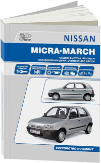
Руководство по эксплуатации, техническому обслуживанию и ремонту автомобилей Nissan March и Nissan Micra 1992-2002 годов выпуска с бензиновыми двигателями моделей CG10DE и CG13DE.
- Автор: —
- Издательство: Автонавигатор
- Год издания: —
- Страниц: 344
- Формат: —
- Размер: —

Руководство по эксплуатации, техническому обслуживанию и ремонту автомобилей Nissan March и Nissan Micra 1992-2002 годов выпуска с бензиновыми двигателями.
- Автор: —
- Издательство: Автонавигатор
- Год издания: —
- Страниц: 416
- Формат: —
- Размер: —
Service Manual Nissan March K13
- Разместил: klays067;
- Прочитано: 1 859;
- Дата: 4-07-2020, 01:35;
-
Руководство на английском языке по техническому обслуживанию и ремонту автомобилей Nissan March и Nissan Micra серии K13.
Страниц: 2741
Формат: PDF

Внимание! Нажимая на ссылку «скачать» Вы обязуетесь, после ознакомления, удалить скаченный файл со своего компьютера.
Всё содержимое сайта autosoftos.com взято из свободных источников, и также свободно распространяется.
Если это Вы являетесь автором данного материала, то, пожалуйста, свяжитесь с нами, для того чтобы обеспечить пользователям, приятную и удобную альтернативу, после ознакомления, покупки качественного «оригинала» непосредственно от издателя. Администрация сайта не несёт никакой ответственности за противоправные действия, и какой либо ущерб, понесённый правообладателями.


+143

Информация
Посетители, находящиеся в группе Гости, не могут оставлять комментарии к данной публикации.
Реклама
Новости
- Установка сигнализации на Volvo S40
- Wurth WOW 5.29.02R2RUS [2014]
- Установка сигнализации на Volkswagen Golf 1998 — 2007
- Bimmer-Tool 3.5.26 Expert
- Установка сигнализации на Volkswagen Vento
- BimmerLink for BMW and Mini 2.29.0-5264 Full
- Предохранители Volvo FH 13 и реле с обозначением и схемами блоков
- Прошивка Bosch 797+ подробная, проверенная инструкция
- Установка сигнализации на Volkswagen Jetta 2000 — 2008
- Предохранители Volvo XC90 и реле с обозначением и схемами блоков
Опрос
Календарь
ACC-2
< PRECAUTION >
PRECAUTIONS
PRECAUTION
PRECAUTIONS
Precaution for Supplemental Restraint System (SRS) «AIR BAG» and «SEAT BELT
PRE-TENSIONER»
INFOID:0000000006046772
The Supplemental Restraint System such as “AIR BAG” and “SEAT BELT PRE-TENSIONER”, used along
with a front seat belt, helps to reduce the risk or severity of injury to the driver and front passenger for certain
types of collision. Information necessary to service the system safely is included in the “SRS AIR BAG” and
“SEAT BELT” of this Service Manual.
WARNING:
• To avoid rendering the SRS inoperative, which could increase the risk of personal injury or death in
the event of a collision which would result in air bag inflation, all maintenance must be performed by
an authorized NISSAN/INFINITI dealer.
• Improper maintenance, including incorrect removal and installation of the SRS, can lead to personal
injury caused by unintentional activation of the system. For removal of Spiral Cable and Air Bag
Module, see the “SRS AIR BAG”.
• Do not use electrical test equipment on any circuit related to the SRS unless instructed to in this
Service Manual. SRS wiring harnesses can be identified by yellow and/or orange harnesses or har-
ness connectors.
PRECAUTIONS WHEN USING POWER TOOLS (AIR OR ELECTRIC) AND HAMMERS
WARNING:
• When working near the Air Bag Diagnosis Sensor Unit or other Air Bag System sensors with the
ignition ON or engine running, DO NOT use air or electric power tools or strike near the sensor(s)
with a hammer. Heavy vibration could activate the sensor(s) and deploy the air bag(s), possibly
causing serious injury.
• When using air or electric power tools or hammers, always switch the ignition OFF, disconnect the
battery, and wait at least 3 minutes before performing any service.
ACCELERATOR CONTROL SYSTEM
ACC-3
< REMOVAL AND INSTALLATION >
C
D
E
F
G
H
I
J
K
L
M
A
ACC
N
P
O
REMOVAL AND INSTALLATION
ACCELERATOR CONTROL SYSTEM
Exploded View
INFOID:0000000005988502
Removal and Installation
INFOID:0000000005988503
REMOVAL
1.
Disconnect accelerator pedal position sensor harness connector.
2.
Loosen mounting bolts, and remove accelerator pedal assembly.
CAUTION:
• Never disassemble accelerator lever. Never remove accelerator pedal position sensor from
accelerator lever.
• Avoid impact from dropping etc. during handling.
• Be careful to keep accelerator lever away from water.
3.
Fold the floor carpet and remove accelerator pedal stopper.
• Remove pedal stopper by turning it counterclockwise with fingers.
INSTALLATION
Note the following, and install in the reverse order of removal.
• Insert locating pin into vehicle side to position accelerator pedal assembly. Tighten mounting bolts to accel-
erator pedal assembly.
Inspection
INFOID:0000000005988504
INSPECTION AFTER INSTALLATION
• Check accelerator pedal moves smoothly within the whole operation range when it is fully depressed and
released.
• Check accelerator pedal securely returns to the fully released position.
• For the electrical inspection of accelerator pedal position sensor. Refer to following;
— HR12DE (TYPE 1):
EC-269, «Component Inspection»
— HR12DE (TYPE 2):
EC-464, «Component Inspection»
CAUTION:
When harness connector of accelerator pedal position sensor is disconnected, perform “ACCELERA-
TOR PEDAL RELEASED POSITION LEARNING”. Refer to following;
• HR12DE (TYPE 1):
EC-104, «Work Procedure»
1.
Accelerator pedal assembly
2.
Bracket
Refer to
GI-4, «Components»
for symbols in the figure.
JPBIA3364GB
ACC-4
< REMOVAL AND INSTALLATION >
ACCELERATOR CONTROL SYSTEM
• HR12DE (TYPE 2):
EC-377, «Work Procedure»
The other day, I was Googling to get the Owners manual of newly launched Nissan Micra K13 also called Nissan March in some countries, Luckily, got the link to download the Nissan Micra Users Manual from team BHP, one of the largest automobile forums. In today’s digital world, having a Digital version of product manuals will be Helpful when you are away from it.
Download the Users Manual for Nissan Micra K13 From Here (Nissan_Micra_K13_User_Manual.pdf)
You may also visit my Earlier posts about Micra here
Thanks
HP Answers


