![]()
|
A |
Foreword |
|
|
B |
Safety |
|
|
C |
Preventive maintenance |
|
|
0 |
Complete machine |
|
Workshop manual |
1 |
Engine |
|
2 |
Transmission |
|
|
3 |
Driveline/axle |
|
|
4 |
Brakes |
|
|
5 |
Steering |
|
|
6 |
Suspension |
|
|
7 |
Load handling |
|
|
8 |
Control system |
|
|
9 |
Frame, body, cab and accessories |
|
|
10 |
Common hydraulics |
|
|
11 |
Common electrics |
|
|
12 |
Common pneumatics |
|
|
D |
Error codes |
|
|
E |
Schematics |
|
|
F |
Technical data |
|
|
G |
Terminology and index |

|
A Foreword |
|
|
Table of Contents A Foreword |
|
|
A Foreword …………………………………………………………………………………. |
3 |
|
About the Workshop Manual …………………………………………………………… |
3 |
|
General ……………………………………………………………………………………………….. |
3 |
|
Workshop manual contents …………………………………………………………………… |
3 |
|
References between different information types …………………………………….. |
4 |
|
Function group breakdown …………………………………………………………………… |
5 |
|
Conditions …………………………………………………………………………………………… |
5 |
|
Storage ……………………………………………………………………………………………….. |
5 |
|
About the machine version …………………………………………………………………… |
5 |
|
Copyright …………………………………………………………………………………………….. |
6 |
|
Reading instructions ………………………………………………………………………. |
7 |
|
Warning information …………………………………………………………………………….. |
7 |
|
Important information ………………………………………………………………………….. |
7 |
|
Read the operator’s manual/maintenance manual ………………………………….. |
7 |
|
Optional equipment ……………………………………………………………………………… |
7 |
|
Function descriptions …………………………………………………………………………… |
8 |
|
About the documentation …………………………………………………………….. |
11 |
|
Documentation sections ……………………………………………………………………… |
11 |
|
Ordering of documentation …………………………………………………………………. |
11 |
|
Feedback …………………………………………………………………………………….. |
12 |
|
Form for copying ………………………………………………………………………………… |
12 |
|
Workshop manual DRF 400–450 |
VDRF01.01GB |

|
VDRF01.01GB |
Workshop manual DRF 400–450 |

|
A Foreword – A Foreword |
3 |
AForeword
BSafety
CPreventive maintenance 0 Complete machine
1Engine
2Transmission
3Driveline/axle
4Brakes
5Steering
6Suspension
7Load handling
8Control system
9Frame, body, cab and accessories 10 Common hydraulics
11 Common electrics
12 Common pneumatics D Error codes
ESchematics
FTechnical data
GTerminology and index
AForeword – Foreword
About the Workshop Manual
General
Thank you for choosing Kalmar Industries as your machine supplier. We hope that we’ll meet your expectations.
Workshop manual contents
The workshop manual contains information for corrective maintenance (replacement of components) and complements the maintenance manual. Accompanying the workshop manual is supplier documentation for engine, transmission and drive axle. Where practicable, please refer from the workshop manual to the maintenance manual and supplier documentation to avoid duplicated information. The workshop manual is divided into the following sections.
General information about the workshop manual’s purpose, contents and reading instructions as well as survey for feedback of views and any inaccuracies.
Keep in mind for your safety.
Reference to maintenance manual: Preventive maintenance.
Technical description, comprehensive function descriptions and a description of the function of components included in the machine, divided into function groups.
The components used for each function are described under each subfunction. Consequently, common components are described in several places, but in general under the first function to use the component.
Together with the general description is a detailed description of what is unique about the specific subfunction. The next subfunction to use the same component only has a description what is unique for the new function.
Work instructions for corrective maintenance (replacement of components).
Reference to maintenance manual: Error code information and instructions for reading error code information.
Reference to maintenance manual: Wiring and hydraulic diagrams
Technical data, conversion tables, information for conversion of units.
General terminology and abbreviations, explanation of terms and abbreviations that can appear in the sections, index for headings in the sections.
|
Workshop manual DRF 400–450 |
VDRF01.01GB |

|
4 |
A Foreword – About the Workshop Manual |
|
References between different information |
|
|
types |
|
|
The maintenance manual and workshop manual are mainly divided |
|
|
into function groups, see Workshop manual contents page 3. Certain |
|
|
parts are broken out as separate parts to increase usability, e.g., |
|
|
“Technical data”. |
|
|
The basic rule of searching for information is to use function groups |
|
|
to find different types of information regarding the function or com- |
|
|
ponent in question. As a complement to this, there are references |
|
|
according to the below. |
|
|
Function descriptions |
Hydraulic diagrams |
|
(Technical description) |
(Section E) |
|
Component descriptions |
Error codes |
|
(Technical description, usually in Workshop manual) |
(Section D) |
|
Diagnostic test |
Wiring diagrams |
|
(Group 8.4) |
(Section E) |
|
• From Function description to Component description, to enable |
|
|
fast finding of more information about the different components |
|
|
that create a function. |
|
|
• From Function description to Hydraulic diagram, to enable fast |
|
|
finding of the right hydraulic diagram for the function in ques- |
|
|
tion. |
|
|
• From Component description or Function description to Diag- |
|
|
nostic test, to enable fast finding of the right diagnostic menu |
|
|
that can be used to check the component (only applies to elec- |
|
|
trical components). |
|
|
• From Diagnostic test to Wiring diagrams. to enable fast finding |
|
|
of the right circuit diagram for further troubleshooting. |
|
|
• From Diagnostic test to Component description or Function de- |
|
|
scription. To enable fast finding of more information about the |
|
|
component’s appearance and position when troubleshooting. |
|
|
• From Error codes to Diagnostic test, to enable fast finding of the |
|
|
right diagnostic menu to troubleshoot component or function in |
|
|
question. |
|
|
• From Error codes to Function description or Component de- |
|
|
scription, to enable fast finding of more information about com- |
|
|
ponents or function. |
|
VDRF01.01GB |
Workshop manual DRF 400–450 |

|
A Foreword – About the Workshop Manual |
5 |
Function group breakdown
Breakdown into function groups is common for all machines from Kalmar Industries, down to two-digit heading level (e.g., 4.3 Powerassisted brake system). Machine-unique adaptations of function groups are done at the third and fourth group levels (e.g., 4.3.9 Wheel brake resp. 4.3.9.1 Disc pack).
This results in certain headings (function groups) being omitted in the documentation for certain machines since the machine lacks that particular function. This means that there may be gaps in the function groups’ numbering (e.g., the three-digit heading level 4.8.7 Oil cooler may be included for certain machines, but may be missing for other machines).
References between manual types (of the type «see Workshop manual DFR 400–450») are used since the different manual types have different purposes and thus different information content.
References between sections within the same manual are indicated using section and group number, e.g., «see section 4 Brakes, group 4.3.9 Wheel brake«. A reference within the same section is indicated with page number, e.g., «see Sensor fuel level, description page 24«.
Conditions
The instructions are based on the use of generally available standard tools. All lifting devices, for example, slings, straps, ratchet blocks, etc., must meet governing national standards and regulations for lifting devices.
Kalmar Industries will not accept any responsibility for modifications performed without permission from Kalmar Industries or if other lifting devices, tools or work methods are used other than those described in this manual.
Storage
NOTE
The Maintenance Manual should be accessible to the service personnel.
About the machine version
The information in this publication corresponds to the machine’s design and appearance at the time of delivery from Kalmar Industries. Due to customizations, there may be variations and/or deviations.
Kalmar Industries reserves the right to modify specifications and equipment without prior notice. All information and data in this manual are valid at the time of publication.
|
Workshop manual DRF 400–450 |
VDRF01.01GB |

|
6 |
A Foreword – About the Workshop Manual |
Copyright
Kalmar Industries AB
Duplication of the content in this manual, in whole or in part, is strictly prohibited without written permission from Kalmar Industries AB.
Duplication by any means such as copying, printing, etc., is prohibited.
|
VDRF01.01GB |
Workshop manual DRF 400–450 |

|
A Foreword – Reading instructions |
7 |
Reading instructions
Warning information
Warnings inform on potential dangers which can, if the warnings are not heeded, result in personal injury or product damage.
D A N G E R
Situation that may result in serious personal injury, possible death, if the instruction is not followed.
W A R N I N G
Situation that may result in serious personal injury if the instruction is not followed.
C A U T I O N
Situation that may result in damage to the product if the instruction is not followed.
Important information
Important information marked with NOTE facilitates the work process, operation/handling or increases understanding of the information.
NOTE
Information that is important without being safety related.
000262
Read the operator’s manual/maintenance manual
Read the operator’s manual/maintenance manual
The symbol to the left is used in certain cases on the machine and refers to important information in the operator’s/maintenance manual.
000264
Indicates optional equipment
Optional equipment
The symbol to the left is used in the manual to indicate that a function or component is optional equipment. Detailed information on how the machine is equipped is presented by the machine card enclosed with the spare parts catalogue.
|
Workshop manual DRF 400–450 |
VDRF01.01GB |

|
8 |
A Foreword – Reading instructions |
Function descriptions
Function descriptions are schematic overviews that describe how a function works as well as which components and signals work together.
Function descriptions describe the function in a logical flow from input signal to desired output signal. Most functions require that preset conditions are fulfilled for the function to be activated. In these cases, the conditions are listed above the illustration.
Function descriptions use symbols to illustrate components such as valves, sensors, etc.
1
10
2
 3
3
9
000520
Example of function description
|
VDRF01.01GB |
Workshop manual DRF 400–450 |
![]()
|
A Foreword – Reading instructions |
9 |
1.Hydraulic force (solid double line)
2.Flag pressure check connection (Check point), indicates that there is pressure check connection for checking pressure signal
3.Flag diagnostic test, indicates that signal can be checked with diagnostic test, see group “8.4 Diagnostic test”
4.Illustration of function, (applied brake)
5.Reference to description of component
6.Signal description, reference value for signal out from component
7.Description of component’s function
8.Position number, reference to position in illustration
9.Position number in illustration, reference to row in table
10.Electric power (solid single line)
|
Workshop manual DRF 400–450 |
VDRF01.01GB |

10
1
3
5
7
9
11
13 
15
17 
19 ˚C
21 ˚C
23 Pa
25
26
28
|
A Foreword – Reading instructions |
||
|
Symbol explanation function descriptions |
||
|
2 |
The following symbols are used in function descriptions, the sym- |
|
|
bols are based on standard symbols used in wiring and hydraulic di- |
||
|
4 |
agrams. |
|
1.Electric control signal
|
6 |
2. |
Electric force |
|
|
3. |
Hydraulic control signal |
||
|
4. |
Hydraulic force |
5.Hydraulic motor
|
8 M |
6. Hydraulic oil pump with variable displacement |
7.Hydraulic oil pump with fixed displacement
|
10 |
8. |
Electric motor |
||
|
9. |
Accumulator |
|||
|
10. |
Disc brake |
|||
|
12 |
11. |
Filter |
||
|
D790-1 |
12. |
Radiator |
||
|
13. |
Bulb |
|||
|
14 |
||||
|
14. |
Control system, two control units with CAN-bus |
|||
|
D797-F |
||||
|
15. |
Restriction |
|||
|
16 |
16. |
Adjustable restriction |
||
|
18 |
17. |
Inductive position sensor |
||
|
18. |
Electrically controlled servo valve |
|||
|
20 |
˚C |
19. |
Thermal by-pass valve |
|
|
22 |
Pa |
20. |
Temperature-controlled switch |
|
|
21. |
Temperature sensor |
|||
|
24 |
22. |
Pressure sensor |
||
|
23. |
Pressure-controlled switch |
|||
|
24. |
Hydraulic cylinder |
|||
|
25. |
Double-acting hydraulic cylinder |
|||
|
26. |
Spring brake cylinder |
|
27 |
27. |
Valve block |
|
|
28. |
Shuttle valve |
||
|
29 |
29. |
Non-return valve |
|
|
000523 |
|||
|
VDRF01.01GB |
Workshop manual DRF 400–450 |

|
A Foreword – About the documentation |
11 |
About the documentation
Documentation sections
The documentation to the machine comprises the following sections:
Operator’s manual
The Operator’s manual is supplied with the machine in the cab.
Documentation kit
Maintenance manual and spare parts catalogue with machine card are supplied with the machine as a separate documentation kit.
Supplementary documentation
There are Supplementary documentation that can be ordered for the machine in the form of a Workshop manual. The Workshop manual includes supplier documentation for engine, transmission and drive axle.
Ordering of documentation
Extra copies and supplementary documentation is ordered from Kalmar Industries.
Kalmar Industries AB SE-341 81 Ljungby, Sweden.
NOTE
If possible, always indicate publication number when ordering.
|
Workshop manual DRF 400–450 |
VDRF01.01GB |

To:
From:
Manual information
Suggestions, views, remarks, etc.
Feedback |
||
Form for copying |
||
|
Kalmar Industries’ ambition is that you who work with maintenance |
||
|
of Kalmar machines shall have access to correct information. |
||
|
Your feedback is important to be able to improve the information. |
||
|
Copy this form, write down your views and send it to us. Thank you |
||
|
for your participation! |
||
|
Kalmar Industries AB |
||
|
Product Support |
||
|
Torggatan 3 |
||
|
SE-340 10 Lidhult |
||
|
SWEDEN |
||
|
Fax: +46 372 263 93 |
||
|
Company / Sender: ………………………………………………………………………………………………………………………… |
||
|
Telephone: ………………………………………………………………………………………………………………………………………. |
||
|
E-mail: …………………………………………………………………………………………………………………………………………….. |
||
|
Date: ……………………………… |
— ……………… |
— ……………… |
|
Name / Publication number: |
…………………………………………………………………………………………………………….. |
|
|
Section / page number: …………………………………………………………………………………………………………………….. |
………………………………………………………………………………………………………………………………………………………..
………………………………………………………………………………………………………………………………………………………..
………………………………………………………………………………………………………………………………………………………..
………………………………………………………………………………………………………………………………………………………..
………………………………………………………………………………………………………………………………………………………..
………………………………………………………………………………………………………………………………………………………..
………………………………………………………………………………………………………………………………………………………..
|
VDRF01.01GB |
Workshop manual DRF 400–450 |

|
B Safe ty |
|
|
Table of Contents B Safety |
|
|
B Safety ………………………………………………………………………………………. |
3 |
|
General safety information ……………………………………………………………… |
3 |
|
Safety concerns everyone! ……………………………………………………………………. |
3 |
|
A near-accident is a warning signal! ………………………………………………………. |
3 |
|
Safety instructions …………………………………………………………………………. |
4 |
|
General ……………………………………………………………………………………………….. |
4 |
|
Service position …………………………………………………………………………………… |
4 |
|
Hydraulic and brake systems, depressurizing ………………………………………….. |
5 |
|
Clothing etc. ………………………………………………………………………………………… |
6 |
|
Several mechanics on the same machine ………………………………………………. |
6 |
|
Working under machine ……………………………………………………………………….. |
7 |
|
Lifting heavy components …………………………………………………………………….. |
7 |
|
Vibrations ……………………………………………………………………………………………. |
8 |
|
Noise ………………………………………………………………………………………………….. |
8 |
|
Solvents ……………………………………………………………………………………………… |
8 |
|
Fire and explosion risks ………………………………………………………………………… |
9 |
|
Fluid or gas under pressure …………………………………………………………………. |
10 |
|
Coolant ……………………………………………………………………………………………… |
11 |
|
Refrigerant ………………………………………………………………………………………… |
12 |
|
Air pollution ………………………………………………………………………………………. |
12 |
|
Tensioned springs ………………………………………………………………………………. |
13 |
|
Electric motors …………………………………………………………………………………… |
14 |
|
Rotating components and tools …………………………………………………………… |
14 |
|
Tyre system ……………………………………………………………………………………….. |
15 |
|
Environment ………………………………………………………………………………… |
16 |
|
General ……………………………………………………………………………………………… |
16 |
|
Workshop manual DRF 400–450 |
VDRF01.01S |

|
VDRF01.01S |
Workshop manual DRF 400–450 |

BSafety – Safety
General safety information
Safety concerns everyone!
The safety information concerns everyone who works with the machine! Persons who do not follow the safety instructions given in this manual must make absolutely sure that the work is performed without risks of personal injury and without risk of damage to machine or property!
Remember to:
•follow the instructions in this manual
•be trained for the work in question
•follow local laws, safety rules and regulations
•use the correct equipment and tools for the job
•wear the correct clothes
•use common sense and work carefully, do not take any risks!
In this publication, Kalmar Industries has documented and warned for situations and risks that may occur/exist in connection with operation as well as service/repairs of the truck under normal conditions.
Therefore, its very important that all who work with the truck, or carry out repairs/service work, acquaint themselves with and act according to the information in the maintenance manual and operators manual.
A near-accident is a warning signal!
A near-accident is an unexpected event where neither persons, machine or property are injured or damaged. However, a near-accident indicates that there is an injury risk and actions must be taken to avoid the risk of injuries.
|
Workshop manual DRF 400–450 |
VDRF01.01S |

|
4 |
B Safety – Safety instructions |
Safety instructions
General
Read, consider and follow the safety instructions below before starting to work in the machine:
•Service position page 4
•Hydraulic and brake systems, depressurizing page 5
•Clothing etc. page 6
•Several mechanics on the same machine page 6
•Working under machine page 7
•Lifting heavy components page 7
•Vibrations page 8
•Noise page 8
•Solvents page 8
•Fire and explosion risks page 9
•Fluid or gas under pressure page 10
•Coolant page 11
•Refrigerant page 12
•Air pollution page 12
•Tensioned springs page 13
•Electric motors page 14
•Rotating components and tools page 14
•Tyre system page 15
Service position
General
Service position is used for service, maintenance and other situations when the machine needs to be secured.
Service position means:
•Machine parked, that is, parking brake applied.
•Boom fully retracted and lowered to horizontal position.
• Engine off.
• Main electric power off (with battery disconnector).
003603
Machine with fully retracted and lowered boom
|
VDRF01.01S |
Workshop manual DRF 400–450 |

|
B Safety – Safety instructions |
5 |
Hydraulic and brake systems, depressurizing
1Machine in service position, see Service position page 4.
2Depressurize the hydraulic system.
Turn the start key to position I and activate extension out, a distinct hissing sound is heard if there is pressure in the hydraulic system. Activate lift, extension and sideshift several times.
3Turn the start key to position 0 and turn off the main electric power.
4 Depressurize the attachment. Open the relief valve top lift.
002269
The above illustration shows closed valve.
|
Workshop manual DRF 400–450 |
VDRF01.01S |

|
6 |
B Safety – Safety instructions |
5Depressurize the brake system by opening the drain valve on the accumulator charging valve.
NOTE
Keep the drain valve open as long as work is in progress.
Clothing etc.
Clothes should be in good condition. Remove loosely hanging clothing (tie, scarf, etc.). Do not wear clothes with wide sleeves, wide trouser legs, etc.
Remove jewelry as it may conduct electricity and get caught in moving parts.
Long hair must be tied up securely, otherwise it may easily get caught in moving parts. Be careful when performing welding work or work requiring open flames since hair catches fire easily.
Several mechanics on the same machine
W A R N I N G
Be extra careful if several mechanics work on the same vehicle, so that unintentional movements do not injury another person. Communicate so that everyone knows where all are and what they are doing.
Risks
Work with wheels or axle suspension, mountings, etc. may result in components on the other side moving and causing damage/injury.
Movements performed from the operator’s station, e.g., movement of lifting equipment, may cause severe personal injuries.
Safety actions
•Make sure that the machine’s lifting equipment is completely lowered or secured in another way.
•Move battery disconnector to position zero, remove the key.
•Be aware of the risks when several persons work around the vehicle.
•Make your co-workers aware of what you’re working with.
•Do not work with drive wheels on the machine’s both sides at the same time.
|
VDRF01.01S |
Workshop manual DRF 400–450 |
![]()
|
B Safety – Safety instructions |
7 |
Working under machine
Working under cab
On machines with cab lift the machine shall be secured in raised position with the intended locks.
Working under chassis
A lifted/raised vehicle may under no circumstances be supported or lifted in parts that belong to the wheel suspension or steering. Always support under the frame or wheel axle.
Risks
Mechanical or hydraulic tools and lifting devices can fall over or accidentally be lowered due to malfunctions or incorrect use.
Lock on lift frame for securing cab in raised position. Safety actions
Use axle stands and supports that stand securely.
Lifting tools should be inspected and type approved for use.
Lifting heavy components
W A R N I N G
Careless handling of heavy components can lead to serious personal injury and material damage.
Use type approved lifting tools or other devices to move heavy components. Make sure that the device is stable and intact.
Risks
Unsuitable lift slings, straps, etc. may break or slip.
The centre of gravity (balance point) of the component can change during the course of the work, and the component may then make unexpected movements which may cause severe personal injuries and material damage.
A component lifted with lifting equipment can start to turn if the equilibrium is upset.
A component lifted using an overhead crane may start to swing back and forth, which can cause severe crushing injuries or material damage.
|
Workshop manual DRF 400–450 |
VDRF01.01S |

|
8 |
B Safety – Safety instructions |
Safety precautions
Lift using a lifting device. Use lifting tools or equipment, especially when such equipment is available for specific work operations. See the workshop manual for methods.
If lifting must be performed without lifting device:
•Lift near the body.
•Keep your back vertical. Raise and lower with legs and arms, do not bend your back. Do not rotate your body while lifting. Ask for assistance in advance.
•Wear gloves. They’re good protection against minor crushing injuries and cuts to fingers.
•Always use protective shoes.
Vibrations
In case of long-term use of vibrating tools, for example, impact nut runners or grinders, injuries may be sustained as vibrations can be transmitted from tools to hands. Especially when fingers are cold.
Safety actions
Use heavy gloves to protect against cold and somewhat against vibrations.
Switch between work duties to give the body time to rest.
Vary work position and grip so that the body is not stressed in only one position by the vibrations.
Noise
Noise louder than 85 dB (A) that lasts for longer than 8 hours is considered harmful to hearing. (Limit values may vary between different countries.) High tones (high frequencies) are more damaging than low tones at the same sound level. Impact noise can also be hazardous, e.g. hammer blows.
Risks
At noise levels higher than the limits hearing damage can occur. In more severe cases, hearing damage can become permanent.
Safety precautions
Use hearing protection. Make sure that it is tested and protects against the noise level in question.
Limit noise with noise-absorbing dividers, for example, noise-ab- sorbing materials in roof and on walls.
Solvents
Fluids that (as opposed to water) dissolve grease, paint, lacquer, wax, oil, adhesive, rubber, etc. are called organic solvents. Examples: White (petroleum) spirits, gasoline, thinner, alcohols, diesel, xylene, trichloroethylene, toluene. Many solvents are flammable and constitute a fire hazard.
|
VDRF01.01S |
Workshop manual DRF 400–450 |

|
B Safety – Safety instructions |
9 |
Risks
Products containing solvents produce vapors that can cause dizziness, headaches and nausea.They may also irritate mucous membranes in the throat and respiratory tracts.
If the solvent comes into direct contact with the skin, this may cause drying and cracking.Risk for skin allergies increases. Solvents may also cause injury if they penetrate through the skin and are absorbed by the blood.
If the body is continuously exposed to solvents, the nervous system may be damaged. Symptoms include sleep disorders, depressions, nervousness, poor memory or general tiredness and fatigue. Continuous inhalation of gasoline and diesel fumes is suspected to cause cancer.
Safety precautions
Avoid inhaling solvent fumes by providing good ventilation, or wearing a fresh-air mask or respiratory device with a suitable filter for the toxic gases.
Never leave a solvent container without tight-sealing lid.
Use solvents with low content of aromatic substances. This reduces the risk of injuries.
Avoid skin contact. Use protective gloves.
Make sure that work clothes are solvent-resistant.
Fire and explosion risks
Examples of explosion-prone substances are oils, petrol, diesel fuel, organic solvents (lacquer, plastic, cleaning agents), rust proofing agents, welding gas, gas for heating (acetylene), high concentration of dust particles of combustible materials. Rubber tyres are highly flammable and cause fires that spread explosively.
Risks
Examples of causes of ignition include welding, cutting, smoking, sparks produced by grinding, inflammable materials coming into contact with hot machine parts, the generation of heat in rags saturated with oil or paint (linseed oil) and oxygen.Oxygen cylinders, lines and valves must be kept free from oil and grease.
Fumes from gasoline, for example, are heavier than air and can thus “run down” a sloping grade, or down into a grease pit, where welding flames, grinding sparks or a burning cigarette can cause an explosion. Evaporated gasoline has a very powerful explosive force.
|
Workshop manual DRF 400–450 |
VDRF01.01S |

|
10 |
B Safety – Safety instructions |
Special cases
Diesel fuel oil with an additive of petrol has a reduced flash point. Explosion risk even at room temperature. The explosion risk due to warmed diesel fuel oil is greater than for gasoline.
When changing oil in the engine, hydraulic system and transmission, keep in mind that the oil may be hot and can cause burn injuries.
Welding on or near the machine. If diesel or other oils have leaked out and have been absorbed by rags, absorbing agent, paper or other porous material, glowing welding sparks can cause ignition and an explosive spread of fire.
When a battery is being charged, the battery electrolyte water is divided into oxygen and hydrogen gas. This mixture is very explosive. The risk of explosion is especially high when a booster battery or a rapid-charge unit is used, as these increase the risk of sparks.
The machines nowadays contain a lot of electronic equipment. During welding work, the control units must be disconnected and current turned off using the battery disconnect switch. Otherwise, strong welding currents can short-circuit the electronics, destroy expensive equipment, and may also cause an explosion or fire.
Welding work must never be carried out on painted surfaces (remove paint by blasting at least 10 cm around the welding or cutting point.) Use gloves, breathing protection and protective safety glasses. Also, welding work must never take place near plastic or rubber materials without first protecting them from the heat. Paints, plastics and rubber generate various substances when heated that may be hazardous to health. Be careful with machines that have been exposed to intense heat or a fire.
Safety precautions
Store hazardous substance in approved and sealed container.
Make sure that there is no ignition source near flammable or explosive substances.
Make sure that ventilation is adequate or there is an air extraction unit when handling flammable substances.
Fluid or gas under pressure
High-pressure lines can be damaged during work, and fluid or gas can stream out.
There may be high pressure in a line even if the pump has stopped. Therefore, gas or fluid can leak out when the connection to the hose is loosened.
A gas cylinder subjected to careless handling can explode, for example, if it falls onto a hard surface. Gas can stream out through damaged valves.
|
VDRF01.01S |
Workshop manual DRF 400–450 |

|
B Safety – Safety instructions |
11 |
Risks
There are injury risks in connection with work on:
•Hydraulic system (for example, working hydraulics and brake system).
•Fuel system.
•Tyre repairs.
•Air conditioning.
Safety precautions
•Use safety glasses and protective gloves.
•Never work in on a pressurized system.
•Never adjust a pressure limiting valve to a higher pressure than recommended by the manufacturer.
•A hydraulic hose that swells, for example, at a connection, is about to rupture. Replace it as soon as possible! Check connections thoroughly.
•Use fluid when checking for leaks.
•Never blow clothes clean with compressed air.
•Discarded pressure accumulators must first be punctured before they are deposited as waste (to avoid risk of explosion). Carefully drill a hole with 3 mm diameter after depressurizing.
•Never use your hands directly to detect a leak.A fine high-pres- sure stream from a hydraulic hose can easily penetrate a hand and causes very severe injuries.
Coolant
The coolant in the machine’s cooling system consists of water, anticorrosion compound and (when needed) anti-freeze fluid, for example, ethylene glycol.
Coolant must not be drained into the sewer system or directly onto the ground.
Risks
The cooling system operates at high pressure when the engine is warm. Hot coolant can jet out and cause scalding in case of a leak or when the expansion tank cap (filler cap) is opened.
Ingesting ethylene glycol and anti-corrosion compound is dangerous and hazardous to health.
Safety precautions
•Use protective gloves and safety glasses if there is a risk of splashing or spraying.
•Open the filler cap first, to release the excess pressure. Open carefully.Hot steam and coolant can stream out.
•If possible, avoid working on the cooling system when the coolant is hot.
|
Workshop manual DRF 400–450 |
VDRF01.01S |

|
12 |
B Safety – Safety instructions |
Refrigerant
Refrigerant is used in the machines air conditioning.
Work on the air conditioning system must be performed by accredited/authorized and trained personnel according to national legislation and local regulations.
Risks
The air conditioning operates at high pressure. Escaping refrigerant can cause freeze burns.
Heated refrigerant (e.g. during the repair of leaks in the A/C system), produces gases that are very toxic if inhaled.
Safety precautions
•Use special instructions and equipment for refrigerant according to the workshop manual when working on the air conditioning system. Special certification and authorization must be held by personnel permitted to do the work. (Follow national legislation and local regulations!)
•Use protective gloves and safety glasses if there’s a risk of leaks.
•Make sure that heat-producing sources or objects are not close by (cigarette glow, welding flame).
Air pollution
Air pollution is the impurities in the air around us and which are regarded as hazardous to health. Certain pollution is more prominent in certain environments.
The following health-hazardous air pollution is especially prominent in workshops:
•Carbon monoxide (fumes) is present in exhaust fumes. Odorless and therefore especially dangerous.
•Nitrogen oxides (nitrous gases) are present in exhaust fumes.
•Welding smoke especially hazardous to health when welding on oily surfaces, galvanized or lacquered materials.
•Oil mist for example, when applying anti-corrosion agent.
•Grinding dust and gases generated when grinding and heating plastics, lacquer, anti-corrosion agents, lubricants, paint, etc.
•Isocyanates are present in certain paints, fillers, adhesives and foam plastics used on machines.
|
VDRF01.01S |
Workshop manual DRF 400–450 |

|
B Safety – Safety instructions |
13 |
Risks
Sulphuric acid mist is corrosive and injures the respiratory tracts. (Generated when heating certain plastics and paints.)
Isocyanates can be released in the form of steam, dust (or may be present in aerosols) when cutting, grinding or welding. Can irritate mucous membranes producing symptoms similar to asthma and impairing lung function. Even brief exposure to high concentrations can give problems with persistent high sensitivity.
Safety precautions
•Make sure of adequate ventilation with fresh air when welding, battery charging and other work when hazardous gases are generated.
•Use suitable gloves and breathing protection when there’s a risk of oil mist. Make sure that protective gear is oil-resistant.
•Apply oil-resistant protective lotion to unprotected skin.
•Make sure that an eye-wash station is in the immediate vicinity when working with corrosive substances.
•Avoid unnecessary operation of the machine inside the workshop. Connect an air extractor to the exhaust pipe so that the exhaust fumes are removed from the workshop.
Tensioned springs
Examples of tensioned springs:
1.Torque springs in pedals for example.
2.Return spring (cup springs) in parking brake cylinder.
3.Lock rings
4.Gas springs
Risks
If a tensioned spring releases, it is shot out by the spring force and can also take adjoining parts with it.
Small springs can cause eye injuries.
Parking brake springs are tensioned with high force and can cause very severe accidents if they are accidentally released in an uncontrolled manner.
Gas springs and gas-charged shock absorbers are tensioned with high force and can cause very severe accidents if they are accidentally released in an uncontrolled manner.
Safety precautions
•Use safety glasses.
•Lock rings should be of a suitable type and in good condition.
•Follow the instructions in this and other manual when performing maintenance and changing parts and components.
•Always use recommended tools.
|
Workshop manual DRF 400–450 |
VDRF01.01S |

|
14 |
B Safety – Safety instructions |
Electric motors
Safety actions
Always turn off the battery disconnector when working on electric motors.
Always block the machine’s wheels, make sure that the parking brake is activated and that the gear selector is in neutral position before starting any work on the machine.
Rotating components and tools
Examples of rotating components and tools:
•Cooling fan
•Drive belts
•Drive shafts
•Drills
•Grinders
Risks
Rotating components, for example, fans or shafts, can cause severe injuries if touched.
Drills, lathes, grinders or other machines with rotating parts can cause severe accidents if clothes or hair get caught and are wound up in the machine.
Safety precautions
•Do not use gloves when working with a drill.
•Remove loose, hanging clothing, scarf or tie.
•Never use clothing with wide sleeves or trouser legs.
•Make sure that clothing is intact and in good condition.
•Long hair should be gathered up in a hair-net or similar.
•Remove large or loose hanging jewellery from hands, arms and neck.
|
VDRF01.01S |
Workshop manual DRF 400–450 |

|
B Safety – Safety instructions |
15 |
Tyre system
D A N G E R
Tyres should be regarded as pressurized containers. They constitute fatal danger if handled incorrectly.
Parts can be thrown with explosive force and may cause severe injuries.
Never repair damaged tyres, rims or lock rings. Tyre repairs should only be performed by authorized personnel.
Risks
Dismantling wheels: Tyres, rims or lock rings can be thrown. Inflating tyres: Tyres, rims and lock rings can be thrown.
Safety actions
•Deflate the tyre before starting to work on the wheel.
•Check that tyres, rims and lock rings aren’t damaged. Never repair damaged rims or lock rings.
•Use protective screen and safety glasses.
|
Workshop manual DRF 400–450 |
VDRF01.01S |

|
16 |
B Safety – Environment |
Environment
General
Ever-increasing industrialisation of our world is having a significant impact on our global environment. Nature, animals and man are subjected daily to risks in connection with various forms of chemical handling.
There are still no environmentally safe chemicals, such as oils and coolants, available on the market. Therefore, all who handle, perform service on or repair machines must use the tools, assisting devices and methods necessary to protect the environment in an environmentally sound manner.
By following the simple rules below, you will contribute to protecting our environment.
Recycling
Deposit discarded materials for recycling or destruction.
Environmentally hazardous waste
Components such as batteries, plastics and other items that may constitute environmentally hazardous waste must be handled and taken care of in an environmentally safe and sound manner.
Discarded batteries contain substances hazardous to personal health and the environment. Therefore, handle batteries in an environmentally safe manner and according to national regulations.
Oils and fluids
Oils freely discharged cause environmental damage and can also be a fire hazard. Therefore, when emptying and draining oils or fuel, take appropriate action to prevent unnecessary spills.
Waste oils and fluids must always be taken care of by an authorised disposal company.
Pay close attention to oil leaks and other fluid leaks! Take immediate action to seal the leaks.
Air conditioning system
The refrigerant in the air conditioning system for the cab adds to the greenhouse effect and may never be intentionally released into open air. Special training is required for all service work on the air conditioning system. Many countries require special certification by an authority for such work.
Working in a contaminated area
Used cab and engine air filters from machines operating in conditions with asbestos dust, or other hazardous dust, must be sealed in air-tight plastic bags before being deposited in the designated area. The machine must be equipped for work in a contaminated area (environmentally contaminated or hazardous to personal health) before work is started. In addition, special local regulations apply when handling and servicing such a machine.
|
VDRF01.01S |
Workshop manual DRF 400–450 |
![]()
C Preventive maintenance |
1 |
C Preventive
maintenance
Preventive maintenance
See Maintenance manual DRF 400–450, section C Preventive maintenance.
|
Workshop manual DRF 400–450 |
VDRF01.01GB |

|
2 |
C Preventive maintenance |
|
VDRF01.01GB |
Workshop manual DRF 400–450 |

0 Complete machine |
1 |
0 Complete machine
Complete machine, description
Kalmar DRF 400–450 is a “Reachstacker” for container handling. The machine has a lift capacity of 40–45 tons depending on version.
The engine is a six cylinder four-stroke direct-injected diesel engine.
The transmission is hydromechanical with gears in constant mesh. It has four forward gears and four reverse gears. The engine power is transmitted with a torque converter.
The driveline/axle consists of a drive shaft and a rigid drive axle with hub reduction. Drive takes place on the front wheels.
The service brake is of the type disc brake in oil which is built together with the drive wheels’ wheel hubs. The parking brake is of the type disc brake and acts on the drive axle’s input shaft.
Steering takes place on the rear wheels with a double-acting hydraulic cylinder. The steering axle is oscillation-mounted in the frame.
The wheels are mounted on the hubs with clamps. Twin wheels are mounted on the drive axle, the steering axle single wheels.
Load handling is components and functions for handling loads. Loads are lifted with an attachment that is mounted on a liftable telescopic boom. Load handling is divided into the functions lift and lower, extension, sideshift, spreading, rotation, tilt, levelling and load carrying. Lift and lower is the function to lift and lower the boom. Extension is the function to push out and retract the boom. Sideshift is to move the attachment sideways in relation to the machine. Spreading is to adjust the width between the attachment’s lifting points. Rotation is to rotate the load in relation to the machine. Tilt is to angle the load in the machine’s longitudinal direction. Levelling is to angle the load in the machine’s lateral direction (sideways). Load carrying is to grab the load.
The control system are functions for warning the operator of dangerous situations and malfunctions. The control system has diagnostic possibilities that facilitate troubleshooting.
The frame supports the machine. The engine, transmission, drive axle and steering axle are mounted in the frame. On the frame’s sides there are tanks for fuel, hydraulic oil and oil for the brake system. The cab is located in the centre and can be moved fore-aft. As an option the cab is available in a side-mounted version that can be raised and lowered.
|
Workshop manual DRF 400–450 |
VDRF01.01GB |

Troubleshooting instructions, general
For instructions, see Maintenance manual DRF 400–450. There are following instructions:
•Troubleshooting, general work instructions
•Troubleshooting without error code, example
•Troubleshooting with error code, example
•Troubleshooting cable harnesses
•Troubleshooting hydraulic hoses
|
VDRF01.01GB |
Workshop manual DRF 400–450 |

1 Engine
Table of Contents 1 Engine
|
1 |
Engine …………………………………………………………………………………………. |
3 |
|
|
1.1 |
Controls and instrumentation ………………………………………………………… |
13 |
|
|
1.1.1 |
Ignition ……………………………………………………………………………………. |
13 |
|
|
1.1.2 |
Accelerator ……………………………………………………………………………… |
14 |
|
|
1.1.3 |
Warning light low oil pressure in engine ……………………………………… |
15 |
|
|
1.1.4 |
Indicator light preheating ………………………………………………………….. |
15 |
|
|
1.1.5 |
Warning light low coolant level ………………………………………………….. |
15 |
|
|
1.1.6 |
Warning light high coolant temperature ……………………………………… |
16 |
|
|
1.1.7 |
Warning light low fuel level ……………………………………………………….. |
16 |
|
|
1.1.8 |
Operating menu engine and transmission …………………………………… |
16 |
|
|
1.1.9 |
Operating menu engine …………………………………………………………….. |
16 |
|
|
1.2 |
Fuel system …………………………………………………………………………………. |
17 |
|
|
1.2.1 |
Fuel tank …………………………………………………………………………………. |
17 |
|
|
1.2.2 |
Sensor fuel level ………………………………………………………………………. |
17 |
|
|
1.2.3 |
Fuel pre-filter …………………………………………………………………………… |
17 |
|
|
1.2.4 |
Fuel filter ………………………………………………………………………………… |
17 |
|
|
1.2.5 |
Sensor water in fuel …………………………………………………………………. |
17 |
|
|
1.2.6 |
Fuel pump ………………………………………………………………………………. |
18 |
|
|
1.2.7 |
Sensor fuel pressure ………………………………………………………………… |
18 |
|
|
1.2.8 |
Injectors ………………………………………………………………………………….. |
18 |
|
|
1.2.9 |
Breaking contact fuel pressure ………………………………………………….. |
18 |
|
|
1.2.10 |
Making contact water in fuel …………………………………………………….. |
18 |
|
|
1.5 |
Mechanical parts …………………………………………………………………………. |
19 |
|
|
1.6 |
Air intake and exhaust outlet ………………………………………………………… |
20 |
|
|
1.6.1 |
Air cleaning system ………………………………………………………………….. |
20 |
|
|
1.6.2 |
Turbo ……………………………………………………………………………………… |
20 |
|
|
1.6.3 |
Exhaust system ……………………………………………………………………….. |
21 |
|
|
1.6.4 |
Intercooler ………………………………………………………………………………. |
22 |
|
|
1.6.5 |
Sensor boost pressure ……………………………………………………………… |
22 |
|
|
1.6.6 |
Sensor charge-air temperature ………………………………………………….. |
22 |
|
|
1.7 |
Cooling system …………………………………………………………………………….. |
23 |
|
|
1.7.1 |
Coolant pump ………………………………………………………………………….. |
23 |
|
|
1.7.2 |
Coolant filter ……………………………………………………………………………. |
23 |
|
|
1.7.3 |
Coolant thermostat ………………………………………………………………….. |
23 |
|
|
1.7.4 |
Radiator and expansion tank …………………………………………………….. |
24 |
|
|
1.7.5 |
Cooling fan ……………………………………………………………………………… |
25 |
|
|
1.7.6 |
Oil cooler ………………………………………………………………………………… |
28 |
|
|
1.7.7 |
Coolant …………………………………………………………………………………… |
28 |
|
|
1.7.8 |
Making contact coolant level …………………………………………………….. |
29 |
|
|
1.7.9 |
Sensor coolant temperature ……………………………………………………… |
29 |
|
|
1.7.10 |
Plug-in heater ………………………………………………………………………….. |
30 |
|
|
1.8 |
Lubrication ………………………………………………………………………………….. |
31 |
|
|
1.8.1 |
Oil sump …………………………………………………………………………………. |
31 |
|
|
1.8.2 |
Oil pump …………………………………………………………………………………. |
31 |
|
Workshop manual DRF 400–450 |
VDRF01.01GB |

|
1.8.3 |
Sensor oil pressure …………………………………………………………………… |
31 |
|
1.8.4 |
Full flow filter …………………………………………………………………………… |
31 |
|
1.8.5 |
By-pass filter ……………………………………………………………………………. |
31 |
|
1.8.6 |
Oil cooler …………………………………………………………………………………. |
31 |
|
1.8.7 |
Sensor oil temperature ……………………………………………………………… |
31 |
|
1.9 |
Control system engine ………………………………………………………………….. |
32 |
|
1.9.1 |
Control unit engine …………………………………………………………………… |
32 |
|
1.10 |
Ignition/heating …………………………………………………………………………….. |
33 |
|
1.10.1 |
Preheating ……………………………………………………………………………….. |
33 |
|
1.11 |
Start/stop …………………………………………………………………………………….. |
34 |
|
1.11.1 |
Start motor ………………………………………………………………………………. |
34 |
|
1.11.2 |
Stop device ……………………………………………………………………………… |
34 |
|
VDRF01.01GB |
Workshop manual DRF 400–450 |

1Engine – Engine
Engine alternative Volvo, function description
|
Condition |
Reference value |
Reference |
|
|
Engine heater |
Disconnected (when cable is in start lock-out is activated) |
Engine heater, description page 30 |
|
|
˚C |
|||
|
0 |
. bar |
||
|
P |
I |
rpm |
|
|
II |
kph |
III
|
2, 11 |
D790-1 |
D790-2 |
6, 15 |
|
|
20, 22 |
D793 |
3, 7, 12 |
D794 |
14, 23 |
|
8 |
M |
SENSORS |
13 |
|
|
4 |
||||
|
9 |
003161
Pos Explanation
1The ignition sends voltage signal to Control unit cab (D790-1) when the start key is turned to position 1 or preheating position.
2Control unit cab (D790-1) sends ignition on via CAN-bus. If the key is turned to preheating position then preheating is also sent on the CANbus.
3If preheating has been activated with start key, then control unit engine (D794) feeds voltage to the preheating coil.
Signal description
U = 24 V
Checked by control system, error shown with error code.
U = 24 V
Reference
Ignition, description page 13
Diagnostic menu, see Maintenance manual DRF 400–450, section 8 Control system, group 8.4.1.4 CAN/POWER, menu 4 and 8.4.6.4 ENGINE, menu 4
Section 11 Common electrics, group 11.6 Communication
Preheating coil, description page 33
Diagnostic menu, see Maintenance manual DRF 400–450, section 8 Control system, group 8.4.6.5 ENGINE, menu 5
|
Workshop manual DRF 400–450 |
VDRF01.01GB |

Pos Explanation
4The preheating coil warms the inlet air for the engine.
5The ignition sends voltage signal to Control unit KIT (D790-2) when the start key is turned to start position.
6Control unit KIT (D790-2) sends start signal on the CAN-bus.
7Control unit engine (D794) feeds voltage to starter motor.
8Starter motor rotates engine.
9The engine’s sensors send signals to Control unit engine (D794) which controls the injectors so that the engine starts.
10Throttle pedal sends voltage signal proportional to downward pressing to Control unit cab (D790-1).
11Control unit cab sends message with rpm request on CAN-bus.
12Control unit engine increases engine rpm.
13Make-contact coolant level sends voltage signal to Control unit engine (D794) if coolant level is low in expansion tank.
Signal description
—
U = 24 V
U = 24 V
—
—
U = 0.5–4.5 V
Lower voltage than 0.5 V and higher voltage than 4.5 V used to detect malfunction in cable harnesses and controls.
Checked by control system, error shown with error code.
—
U = 24 V
Reference
Preheating coil, description page 33
Diagnostic menu, see Maintenance manual DRF 400–450, section 8 Control system, group 8.4.6.5 ENGINE, menu 5
Ignition, description page 13
Diagnostic menu, see Maintenance manual DRF 400–450, section 8 Control system, group 8.4.1.4 CAN/POWER, menu 4 and 8.4.6.4 ENGINE, menu 4
Section 11 Common electrics, group 11.6 Communication
Starter motor, description (Volvo engine) page 34
Diagnostic menu, see Maintenance manual DRF 400–450, section 8 Control system, group 8.4.6.5 ENGINE, menu 5
Starter motor, description (Volvo engine) page 34
Diagnostic menu, see Maintenance manual DRF 400–450, section 8 Control system, group 8.4.6.5 ENGINE, menu 5
Section 11 Common electrics, group 11.5.3.10 Control unit engine
Accelerator pedal, description page 14
Diagnostic menu, see Maintenance manual DRF 400–450, section 8 Control system, group 8.4.6.1 ENGINE, menu 1
Section 11 Common electrics, group 11.6 Communication
Section 11 Common electrics, group 11.5.3.10 Control unit engine
Cooling system, description page 23
|
VDRF01.01GB |
Workshop manual DRF 400–450 |

Pos Explanation
14Control unit engine sends engine data and warning messages on CAN-bus.
15Control unit KID (D795) shows engine data via display figures.
16Sensor fuel level (B757) sends voltage signal proportional to fuel level in tank to Control unit frame rear (D797-R).
17Control unit frame rear (D797-R) sends fuel level on CAN-bus.
18Control unit KID (D795) shows fuel level in operating menu for engine.
19Sensor output shaft (B758) sends pulses with frequency proportional to rpm on output shaft to control unit transmission (D793).
20Control unit transmission (D793) sends speed on CAN-bus.
21Control unit KID (D795) shows the machine’s speed.
22If the rpm on the output shaft is so high that it matches the limit for the machine’s speed limitation, then Control unit transmission (D793) sends reduce engine rpm on the CAN-bus.
23Control unit engine (D794) restricts engine rpm.
Signal description
Checked by control system, error shown with error code.
—
U = 0.5–4.5 V
Lower voltage than 0.5 V and higher voltage than 4.5 V used to detect malfunction in cable harnesses and controls.
Checked by control system, error shown with error code.
—
—
Checked by control system, error shown with error code.
—
Reference
Section 11 Common electrics, group 11.6 Communication
Diagnostic menu, see Maintenance manual DRF 400–450, section 8 Control system, group 8.4.6.6 ENGINE, menu 6 and 8.4.6.7 ENGINE, menu 7
Operating menu engine and transmission, description page 16Operating menu engine, description page 16
Sensor fuel level, description page 17
Diagnostic menu, see Maintenance manual DRF 400–450, section 8 Control system, group 8.4.3.7 CAB, menu 7
Section 11 Common electrics, group 11.6 Communication
Operating menu engine, description page 16
Section 2 Transmission, group 2.3.8 Sensor output shaft
Diagnostic menu, see Maintenance manual DRF 400–450, section 8 Control system, group 8.4.7.6 TRANSM, menu 6
Section 11 Common electrics, group 11.6 Communication
Section 11 Common electrics, group 11.5.3.12 Control unit KID
Section 11 Common electrics, group 11.6 Communication
Section 11 Common electrics, group 11.5.3.10 Control unit engine
|
Workshop manual DRF 400–450 |
VDRF01.01GB |

Engine and gearbox, separation (Volvo engine)
Separation
1Machine in service position, see section B Safety.
2Detach relevant hoses and cables before separating engine and gearbox.
NOTE
Drain and collect liquids before detaching hoses.
3 Attach hoisting equipment to the engine.
4 Use a jack to secure the gearbox.
5Remove the plugs ahead of the flywheel.
The outer hole is used for turning the engine over.
6Remove the flexible plate retaining screws. Turn the engine over until the flexible plate screws are visible through the inner hole. The flexible plate has eight attachment points that must be undone.
7Take up the slack in the hoisting equipment.
NOTE
Do not raise the engine or gearbox.
|
VDRF01.01GB |
Workshop manual DRF 400–450 |
![]()
8Remove the screws between engine and gearbox.
9Remove the engine or gearbox brackets and separate engine and gearbox.
Assembly
10Check that the holes for securing the flexible plate to the flywheel are in line with the plate retaining nuts.
The flexible plate has eight attachment points that must be connected to the flywheel on the engine.
11Fit the engine or gearbox brackets. Tighten to a torque of 168 Nm.
12Connect the engine to the gearbox.
13Insert the screws between engine and gearbox. Tighten to a torque of 40 Nm.
14Fit the flexible plate retaining screws. Tighten to a torque of 40 Nm.
NOTE
To remove a dropped screw the engine must be detached from the engine brackets and separated from the gearbox. Secure the screw in the sleeve on assembly.
15Fit the plugs ahead of the flywheel.
16Remove the hoisting equipment from the engine.
17Remove the jack from underneath the gearbox.
18Attach relevant hoses and cables to engine and gearbox. Check fluid levels and top up as necessary.
|
Workshop manual DRF 400–450 |
VDRF01.01GB |

8 1 Engine – 1 Engine
|
Engine alternative Cummins, |
||
|
function description |
||
|
Condition |
Reference value |
Reference |
|
Engine heater |
Disconnected (when cable is in start lock-out is activated) Engine heater, description page 30 |
|
|
˚C |
||
|
0 |
. bar |
|
|
P |
I |
rpm |
|
II |
kph |
|
2, 9 |
D790-1 |
D790-2 |
4, 13 |
D795 16, |
19 |
|
|
18, 20 |
D793 |
5, 10 |
D794 |
12, 21 |
D797-R 15 |
|
17 |
SENSORS |
M 6 |
|
|
H2O |
003162 |
||
|
11 |
7 |
14 |
Pos Explanation
1The ignition sends voltage signal to Control unit cab (D790-1) when the start key is turned to position 1.
2Control unit cab (D790-1) sends ignition on start message on CANbus.
3The ignition sends voltage signal to Control unit KIT (D790-2), when the start key is turned to start position.
4Control unit KIT (D790-2) sends start signal on the CAN-bus.
Signal description
U = 24 V
Checked by control system, error shown with error code.
U = 24 V
Checked by control system, error shown with error code.
Reference
Ignition, description page 13
Diagnostic menu, see Maintenance manual DRF 400–450, section 8 Control system, group 8.4.1.4 CAN/POWER, menu 4 and 8.4.6.4 ENGINE, menu 4
Section 11 Common electrics, group 11.6 Communication
Ignition, description page 13
Diagnostic menu, see Maintenance manual DRF 400–450, section 8 Control system, group 8.4.1.4 CAN/POWER, menu 4 and 8.4.6.4 ENGINE, menu 4
Section 11 Common electrics, group 11.6 Communication
|
VDRF01.01GB |
Workshop manual DRF 400–450 |

Pos Explanation
5Control unit frame rear (D797-R) feeds voltage to starter motor.
6Starter motor rotates engine
7The engine’s sensors send signals to Control unit engine (D794) which controls the injectors so that the engine starts.
8Throttle pedal sends voltage signal proportional to downward pressing to Control unit cab (D790-1).
9Control unit cab sends message with rpm request on CAN-bus.
10Control unit engine increases engine rpm.
11Make-contact coolant level sends voltage signal to Control unit engine (D794) if coolant level is low in expansion tank.
12Control unit engine (D794) sends engine data and warning messages on CAN-bus.
13Control unit KID (D795) shows engine data via display figures.
14Sensor fuel level (B757) sends voltage signal proportional to fuel level in tank to Control unit frame rear (D797-R).
Signal description
U = 24 V
—
—
U = 0.5–4.5 V
Lower voltage than 0.5 V and higher voltage than 4.5 V used to detect malfunction in cable harnesses and controls.
Checked by control system, error shown with error code.
—
U = 24 V
Checked by control system, error shown with error code.
—
U = 0.5–4.5 V
Lower voltage than 0.5 V and higher voltage than 4.5 V used to detect malfunction in cable harnesses and controls.
Reference
Starter motor, description (Cummins engine) page 34
Diagnostic menu, see Maintenance manual DRF 400–450, section 8 Control system, group 8.4.6.5 ENGINE, menu 5
Starter motor, description (Cummins engine) page 34
Diagnostic menu, see Maintenance manual DRF 400–450, section 8 Control system, group 8.4.6.5 ENGINE, menu 5
Section 11 Common electrics, group 11.5.3.10 Control unit engine
Accelerator pedal, description page 14
Diagnostic menu, see Maintenance manual DRF 400–450, section 8 Control system, group 8.4.6.1 ENGINE, menu 1
Section 11 Common electrics, group 11.6 Communication
Section 11 Common electrics, group 11.5.3.10 Control unit engine
Cooling system, description page 23
Section 11 Common electrics, group 11.6 Communication
Diagnostic menu, see Maintenance manual DRF 400–450, section 8 Control system, group 8.4.6.6 ENGINE, menu 6 and 8.4.6.7 ENGINE, menu 7
Operating menu engine and transmission, description page 16Operating menu engine, description page 16
Sensor fuel level, description page 17
Diagnostic menu, see Maintenance manual DRF 400–450, section 8 Control system, group 8.4.3.7 CAB, menu 7
|
Workshop manual DRF 400–450 |
VDRF01.01GB |

Pos Explanation
15Control unit frame rear (D797-R) sends fuel level on CAN-bus.
16Control unit KID (D795) shows fuel level in operating menu for engine.
17Sensor output shaft (B758) sends pulses with frequency proportional to rpm on output shaft to control unit transmission (D793).
18Control unit transmission (D793) sends “reduce engine rpm” on CAN-bus.
19Control unit KID (D795) shows the machine’s speed.
20If the rpm on the output shaft is so high that it matches the limit for the machine’s speed limitation, then Control unit transmission (D793) sends reduce engine rpm on the CAN-bus.
21Control unit engine (D794) restricts engine rpm.
Signal description
Checked by control system, error shown with error code.
—
—
Checked by control system, error shown with error code.
—
Checked by control system, error shown with error code.
—
Reference
Section 11 Common electrics, group 11.6 Communication
Operating menu engine, description page 16
Section 2 Transmission, group 2.3.9 Sensor output shaft
Diagnostic menu, see Maintenance manual DRF 400–450, section 8 Control system, group 8.4.7.6 TRANSM, menu 6
Section 11 Common electrics, group 11.6 Communication
Section 11 Common electrics, group 11.5.3.12 Control unit KID
Section 11 Common electrics, group 11.6 Communication
Section 11 Common electrics, group 11.5.3.10 Control unit engine
|
VDRF01.01GB |
Workshop manual DRF 400–450 |

Engine and gearbox, separation (Cummins engine)
Separation
1Machine in service position, see section B Safety.
2Attach hoisting equipment to the engine.
3Detach relevant hoses and cables before separating engine and gearbox.
NOTE
Drain and collect liquids before detaching hoses.
4 Use a jack to secure the gearbox.
5Remove the cover plate in front of the flywheel.
6Remove the flexible plate retaining screws. Turn engine over until one of the flexible plate screws is visible through the hole.
7Take up the slack in the hoisting equipment.
NOTE
Do not raise the engine.
8Remove the screws between engine and gearbox.
9Remove the engine or gearbox brackets.
10Withdraw the engine rearwards to separate it from the gearbox.
Assembly
11Rotate the engine until the holes in the flywheel are in line with the flexible plate attachment points.
The flexible plate has eight attachment points that must be connected to the flywheel on the engine.
12Fit the screws in the engine bracket. Tighten to a torque of 168 Nm.
13Connect the engine to the gearbox.
14Fit the screws between engine and gearbox. Tighten to a torque of 52 Nm.
|
Workshop manual DRF 400–450 |
VDRF01.01GB |

15Fit the flexible plate retaining screws. Tighten to a torque of 40 Nm.
NOTE
To remove a dropped screw the engine must be detached from the engine brackets and separated from the gearbox. Secure the screw in the sleeve on assembly.
16Fit the plug in front of the flywheel.
17Remove the hoisting equipment from the engine.
18Remove the jack from underneath the gearbox.
19Attach relevant hoses and cables to engine and gearbox. Check fluid levels and top up as necessary.
|
VDRF01.01GB |
Workshop manual DRF 400–450 |

|
1 Engine – 1.1 Controls and instrumentation |
13 |
000317
1.1Controls and instrumentation
1.1.1Ignition
Ignition, description
P No function.
0 Stop position. Everything is off, key can be removed.
IOperating position.
Voltage to all electrical functions. Control units for engine and transmission are now ready for start.
The signal can be checked from the diagnostic menu, see
Maintenance manual DRF 400–450, section 8 Control system, group 8.4.1.4 CAN/POWER, menu 4.
IIPreheating position.
In preheating position, the engine’s inlet air is preheated with a preheating coil to a suitable temperature. Indicator light for preheating is activated during preheating.
The signal can be checked from the diagnostic menu, see
Maintenance manual DRF 400–450, section 8 Control system, group 8.4.6.4 ENGINE, menu 4.
IIIStart position.
Engagement of starter motor for engine start.
NOTE
The machine is equipped with an electric restart interlock, which prevents engagement of the starter motor when the engine is rotating.
Condition for starter motor to engage is that transmission is in neutral position and that the engine isn’t already running.
The signal can be checked from the diagnostic menu, see
Maintenance manual DRF 400–450, section 8 Control system, group 8.4.6.4 ENGINE, menu 4.
|
Workshop manual DRF 400–450 |
VDRF01.01GB |

14
A
A. Accelerator pedal
1.Brake pedal
2.Throttle pedal
1 Engine – 1.1.2 Accelerator
1.1.2Accelerator
Accelerator pedal, description
The accelerator pedal controls the engine’s torque and rpm.
The accelerator pedal acts on a rotary potentiometer which gives a signal to Control unit cab (D790-1). The accelerator pedal’s positions are factory calibrated but may need to be recalibrated if the pedal is replaced.
The signal can be checked from the diagnostic menu, see Maintenance manual DRF 400–450, section 8 Control system, group 8.4.6.1 ENGINE, menu 1.
001514
Accelerator pedal, change
1Machine in service position, see section B Safety.
2Pull one edge of the cover away to facilitate access to the accelerator pedal.
3Unplug the cable from the connector.
4Unscrew the connector from the accelerator pedal.
5Change the accelerator pedal.
6Fit in the reverse order.
7Calibrate the accelerator pedal, see section 8 Control system, group 8.5.2.3 Calibrate DRIVE-TRAIN.
Accelerator pedal, calibration
See section 8 Control system, group 8.5.2.3 Calibrate DRIVE-TRAIN.
|
VDRF01.01GB |
Workshop manual DRF 400–450 |

|
1 Engine – 1.1.3 Warning light low oil pressure in engine |
15 |
000303
1.1.3Warning light low oil pressure in engine
Warning light low oil pressure in engine, description
The warning light is activated when the engine’s oil pressure is so low that there is a risk of damage. The warning light is supplied with voltage by Control unit KIT (D790-2) and is located in the light panel.
Volvo engine: If the oil pressure is low, the engine rpm is reduced for three seconds, then the engine is turned off. The engine can be restarted and run for intervals of 30 seconds.
000304
NOTE
Restart may result in engine breakdown.
Low engine oil pressure warning lamp, change
The lamp is part of the Kalmar Information Terminal, KIT. Not changed separately. See section 8 Control system, group 8.1.1 Information terminal.
1.1.4Indicator light preheating
Indicator light preheating, description
Only applies to Volvo engines.
The preheating indicator light is on during the engine’s preheating period. The indicator light is supplied with voltage by Control unit KIT (D790-2) and is located in the light panel.
000305
Preheating indicator lamp, change
The lamp is part of the Kalmar Information Terminal, KIT. Not changed separately. See section 8 Control system, group 8.1.1 Information terminal.
1.1.5Warning light low coolant level
Warning light, low engine coolant level, description
The warning light is activated if the coolant level is too low. The indicator light is supplied with voltage by Control unit KIT (D790-2) and is located in the light panel.
Volvo engine: If the coolant level is low, the engine rpm is reduced for three seconds, then the engine is turned off. The engine can be restarted and run for intervals of 30 seconds.
NOTE
Restart may result in engine breakdown.
Low engine coolant level warning lamp, change
The lamp is part of the Kalmar Information Terminal, KIT. Not changed separately. See section 8 Control system, group 8.1.1 Information terminal.
|
Workshop manual DRF 400–450 |
VDRF01.01GB |

|
16 |
1 Engine – 1.1.6 Warning light high coolant temperature |
000302
1.1.6Warning light high coolant temperature
Warning light high coolant temperature, description
The warning light is activated if the engine’s coolant temperature should become too high. The warning light is supplied with voltage by Control unit KIT (D790-2) and is located in the light panel.
Volvo engine: If coolant temperature exceeds 100 °C, engine rpm is restricted to approx. 1000 rpm.
000307
High coolant temperature warning lamp, change
The lamp is part of the Kalmar Information Terminal, KIT. Not changed separately. See section 8 Control system, group 8.1.1 Information terminal.
1.1.7Warning light low fuel level
Warning light low fuel level, description
The warning light is activated when approx. 17% of the fuel remains, which corresponds to approx. 5 hours operating time. The warning light is supplied with voltage by Control unit KIT (D790-2) and is located in the light panel.
Low fuel level warning lamp, change
The lamp is part of the Kalmar Information Terminal, KIT. Not changed separately. See section 8 Control system, group 8.1.1 Information terminal.
1.1.8Operating menu engine and transmission
Operating menu engine and transmission, description
a.Shows current engine rpm.
b.Shows current speed in km/h (in display kilometer per hour, kph).
c.Shows current gear.
Travel direction and shifting program are shown on steering wheel panel.
d.Shows current fuel level.
1.1.9Operating menu engine
Operating menu engine, description
a.Shows coolant temperature in °C.
Volvo engine: If coolant temperature exceeds 100 °C, engine rpm is restricted to approx. 1000 rpm.
b.Shows engine oil pressure in bar.
|
VDRF01.01GB |
Workshop manual DRF 400–450 |
 Loading…
- Manuals
- Brands
- Kalmar Manuals
- Forklifts
- DRF450-65S5
Manuals and User Guides for Kalmar DRF450-65S5. We have 1 Kalmar DRF450-65S5 manual available for free PDF download: Maintenance Manual
Kalmar DRF450-65S5 Maintenance Manual (600 pages)
Brand: Kalmar
|
Category: Forklifts
|
Size: 15.58 MB
Table of Contents
-
A Foreword
3
-
Table of Contents
3
-
Storage
5
-
Copyright
5
-
About the Machine Version
5
-
MM MM MM MM
5
-
Conditions
5
-
Foreword
5
-
General
5
-
About the Maintenance Manual
5
-
Reading Instructions
6
-
Warning Information
6
-
Important Information
6
-
Read Operator’s Manual
6
-
Read Maintenance Manual
6
-
Maintenance Manual’s Content
7
-
Function Group Structure
8
-
References between Different Information Types
9
-
Product Alternatives and Optional Equipment
9
-
Machine Card
10
-
Function Descriptions
11
-
About the Documentation
14
-
Documentation Sections
14
-
Ordering of Documentation
14
-
Feedback
15
-
Form for Copying
15
-
-
B Safety
17
-
A Near-Accident Is a Warning Signal
19
-
General Safety Information
19
-
MM MM MM MM
19
-
Safety
19
-
Safety Concerns Everyone
19
-
General
20
-
Safety Instructions
20
-
Service Position
20
-
Hydraulic and Brake Systems, Depressurizing
21
-
Clothing Etc
22
-
Several Mechanics on the same Machine
22
-
Lifting Heavy Components
23
-
Working under Machine
23
-
Noise
24
-
Vibrations
24
-
Fire and Explosion Risks
25
-
Solvents
25
-
Fluid or Gas under Pressure
26
-
Coolant
27
-
Air Pollution
28
-
Refrigerant
28
-
Tensioned Springs
29
-
Electric Motors
30
-
Rotating Components and Tools
30
-
Tyre System
31
-
Environment
32
-
General
32
-
-
C Preventive Maintenance
33
-
MM MM MM MM
35
-
Preventive Maintenance
35
-
Preventive Maintenance, General
35
-
Preventive Maintenance, Work Instructions
35
-
Check and Service Log
36
-
50H-Check
37
-
Service Schedule
39
-
Washing
45
-
Lubrication 500 Hours
46
-
Lubrication 1000 Hours
48
-
-
Complete Machine
51
-
Complete Machine
53
-
Complete Machine, Description
53
-
MM MM MM MM
53
-
Troubleshooting, General Work Instructions
54
-
Troubleshooting with Error Code, Example
55
-
Troubleshooting Without an Error Code, Example
55
-
Troubleshooting Cable Harness
57
-
Troubleshooting Hydraulic Hoses
58
-
-
Engine
59
-
Engine
61
-
MM MM MM MM
61
-
Fuel System
67
-
Fuel Pre-Filter
68
-
Fuel Filter
70
-
Air Cleaning System
72
-
Air Intake and Exhaust Outlet
72
-
Coolant Filter
73
-
Cooling System
73
-
Cooling Fan
76
-
Coolant
77
-
Lubrication
78
-
Control System Engine
82
-
Ignition/Heating
83
-
Start/Stop
84
-
-
Transmission
85
-
MM MM MM MM
87
-
Transmission
87
-
Torque Converter/Clutch System
89
-
Mechanical Transmission
90
-
Lubrication
91
-
Cooling
94
-
Control System Transmission
95
-
-
Brakes
105
-
Brakes
107
-
MM MM MM MM
107
-
Brake Pedal
108
-
Controls and Instrumentation
108
-
Service Brake System
109
-
Brake Oil Pump
112
-
Accumulator
113
-
Parking Brake System
114
-
Parking Brake Unit
115
-
Temperature Control, Filtration and Brake Fluid
117
-
Brake Oil Filter
119
-
Breather Filter
119
-
Oil Brake System
121
-
-
Suspension
129
-
MM MM MM MM
131
-
Suspension
131
-
Steering Axle Cradle
132
-
Suspension
132
-
Wheel Hub
133
-
Wheel Spindle
133
-
Tyre and Rim System
135
-
Tyres
145
-
Rims
146
-
-
Load Handling
149
-
Load Handling
151
-
MM MM MM MM
151
-
Lifting/Lowering
152
-
Servo Filter
155
-
Pressure Reducer
157
-
Protruding
158
-
Lift Boom
161
-
Side-Shift
162
-
Sideshift Frame
164
-
Main Beam Attachment
165
-
Positioning
167
-
Positioning Chains
171
-
Positioning Motor
171
-
Positioning Beam
174
-
Rotation
175
-
Rotation Motor Unit
178
-
Tilt
179
-
Levelling
185
-
Load Carrying
189
-
Twistlocks
189
-
Lift Legs
194
-
Additional Functions
204
-
Support Jacks
204
-
Weight Indicator
206
-
Container Counter
213
-
Synchronous Lift
215
-
-
Control System
217
-
Control System
219
-
MM MM MM MM
219
-
Monitoring
222
-
Overloading System
222
-
By-Passing
227
-
Load Centre Limitation
227
-
Height Limitation
228
-
Service Indicator
228
-
Speed Limitation
228
-
Error Codes
229
-
Diagnostics
231
-
Can/Power
234
-
Lights
235
-
Cab
236
-
Climate
237
-
Hyd
237
-
Engine
238
-
Transm
239
-
Boom
240
-
Attach
241
-
Extra
243
-
Setup
247
-
-
Frame, Body, Cab and Accessories
249
-
Frame, Body, Cab and Accessories
251
-
MM MM MM MM
251
-
Controls and Instrumentation
252
-
Protection and Emergency Equipment
258
-
Seat
259
-
Hvac
260
-
Fresh Air Filter
265
-
Condenser
266
-
Humidity Filter
266
-
Wiper/Washer System
268
-
Lighting System
269
-
Communication Systems
270
-
Entertainment and Communication
271
-
Glass/Windows/Mirrors
272
-
Cab Structure and Suspension
273
-
Longitudinal Displacement of Cab
273
-
Vertically Adjustable Cab
276
-
Cab Interior
279
-
Frame
280
-
Body
281
-
Central Lubrication
282
-
Paint/Coatings
283
-
-
Common Hydraulics
285
-
10 Common Hydraulics
287
-
MM MM MM MM
287
-
Security Valves
289
-
Tanks and Accumulators
290
-
Pumps
291
-
Axial Piston Pump with Variable Displacement
292
-
Hoses, Pipes and Valves
295
-
Temperature Control, Cleaning and Hydraulic Oil
296
-
5. Breather Filter, Hydraulic Oil Tank
299
-
Hydraulic Oil Filter
300
-
Hydraulic Oil
301
-
Hydraulic Oil Fine-Filter
302
-
-
Common Electrics
303
-
11 Common Electrics
305
-
MM MM MM MM
305
-
Electric Protection
306
-
Fuses
307
-
Batteries
310
-
Start Battery
310
-
Alternator
311
-
Distribution of Electricity
312
-
Voltage Feed
312
-
Control Units
317
-
CAN-Bus
318
-
CAN-Bus Driveline
318
-
Communication
318
-
Redundant CAN-Bus
318
-
-
D Error Codes
319
-
Error Codes
321
-
Error Codes, Explanation
321
-
MM MM MM MM
321
-
Reading out Error Code
322
-
Engine
324
-
Error Codes Engine Alternative Cummins
324
-
Error Codes Engine Alternative Volvo
324
-
Error Codes Transmission
357
-
Transmission
357
-
Control System
372
-
Error Codes Machine
372
-
-
E Schematics
411
-
10 Common Hydraulics
413
-
Hydraulic Diagrams, Compilation
413
-
MM MM MM MM
413
-
Hydraulic Diagram Basic Machine
414
-
Hydraulic Diagram Top Lift
416
-
Hydraulic Diagram Top Lift, Tilt Lock and Controllable Tilt
418
-
Hydraulic Diagram Top Lift, Tilt Lock, Controllable Tilt and Hydraulic Levelling
420
-
Hydraulic Diagram Joystick Steering
422
-
Hydraulic Diagram Sliding Cab
424
-
Hydraulic Diagram Cab Lift and Support Jacks
426
-
Hydraulic Diagram Sliding Cab and Support Jacks
428
-
Hydraulic Diagram Combi Attachment (Part 1 of 3)
430
-
Hydraulic Diagram Combi Attachment (Part 2 of 3)
432
-
Hydraulic Diagram Combi Attachment (Part 3 of 3)
434
-
11 Common Electrics
436
-
Circuit Diagrams, Description
436
-
Component Designations
437
-
Circuit Diagrams, Compilation
438
-
-
F Technical Data
571
-
MM MM MM MM
573
-
Specifications for Data and Volume
573
-
Technical Data
573
-
Specifications for Lift Capacity and Dimensions
575
-
Oils and Lubricants, Recommendation
578
-
Tightening Torques, Recommendations
580
-
Tightening Torques, ORFS-Couplings
581
-
Unit Explanations
583
-
Conversion Table, SI-Units
584
-
Conversion Table, Area
585
-
Conversion Table, Length
585
-
Conversion Table, Volume
585
-
Conversion Table, Pressure
586
-
Conversion Table, Weight
586
-
Advertisement
Advertisement
Related Products
-
Kalmar DRF450-60S5
-
Kalmar DRF450-60S5X
-
Kalmar DRF450-65S6
-
Kalmar DRF450-65S5X
-
Kalmar DRF450-65S6X
-
Kalmar DRF450-70S5X
-
Kalmar DRF450-70S5XS
-
Kalmar DRF450-705XS
-
Kalmar DRF420-65S5
-
Kalmar DRF420-65S6
Kalmar Categories
Tractor
Trucks
Forklifts
Industrial Equipment
More Kalmar Manuals

|
Title |
File Size |
Download Links |
|
Kalmar DRF KDU Training Presentation [PPT] |
250.5kb |
Download |
|
Contmaster 45 Tons Technical Information Container Handler |
405.3kb |
Download |
|
Kalmar ContChamp Onderhoud DRD-GB DRD-S technical handbook |
8.7Mb |
Download |
|
Kalmar DCD90-180 Tchnical Handbook [PDF] |
11.4Mb |
Download |
|
Kalmar DCE 90–180, DCE 70-32E3–70-35E4 2006 Workshop Manual |
51.4Mb |
Download |
|
Kalmar DCE90-180, diesel forklift — technical information |
747.2kb |
Download |
|
Kalmar DCF360-450CSG Toplift container handlers 36 – 45 tonnes |
1017.7kb |
Download |
|
Kalmar DCG90-180Lift trucks 9 – 18 tonnes [PDF] |
726.9kb |
Download |
|
Kalmar DNG3196 [PDF] |
679.3kb |
Download |
|
Kalmar DRD 420 Schematic [PDF] |
1.1Mb |
Download |
|
Kalmar DRD-S Tchnical Handbook [PDF] |
8.7Mb |
Download |
|
KALMAR DRF 400-450 Maintenance Manual [PDF] |
16.7Mb |
Download |
|
Kalmar DRF 400-450 Workshop Manual [PDF] |
26.5Mb |
Download |
|
Kalmar DRF 400–450 Error Codes List [PDF] |
5.6Mb |
Download |
|
Kalmar DRF400-450C Reachstackers de 40 – 45 tonedalas [PDF] |
680.8kb |
Download |
|
Kalmar DRF420-450L Technical brochure [PDF] |
4.3Mb |
Download |
|
Kalmar DRF450 Workshop Manual [PDF] |
29.3Mb |
Download |
|
Kalmar DRT450 Reach Stacker Spec [PDF] |
3.8Mb |
Download |
|
Kalmar DRT450 VDRT02 / 02GB Reachstackers Workshop Manual |
39.3Mb |
Download |
|
Kalmar Drt450 [PDF] |
906.9kb |
Download |
|
Kalmar montacargas DCE 90–180, DCE 70-32E3–70-35E Workshop Manual |
51.4Mb |
Download |
|
Kalmar ReachStackers 42-45 t [PDF] |
635.4kb |
Download |
|
Kalmar Rs045xx Drf450 Service Manual [PDF] |
18Mb |
Download |
|
Kalmar RT240 Handler 6pp Web [PDF] |
407.2kb |
Download |
|
Kalmar RT240 Technical Brochure [PDF] |
1.8Mb |
Download |
|
Reach Stackers Kalmar [PDF] |
1.2Mb |
Download |
![]()
Contmaster 45 Tons Technical Information Container Handler
Contmaster 45 Tons Technical Information
Adobe Acrobat Document
569.2 KB
![]()
Kalmar DC 9-16 Spare Parts Catalogue
Kalmar DC 9-16 Spare Parts Catalogue.pdf
Adobe Acrobat Document
17.5 MB
![]()
Kalmar ContChamp Onderhoud DRD-GB DRD-S technical handbook
Kalmar ContChamp Onderhoud DRD-GB DRD-S
Adobe Acrobat Document
8.8 MB
![]()
Kalmar DCD 200-300 Parts Manual
Kalmar DCD 200-300 Parts Manual.pdf
Adobe Acrobat Document
15.5 MB
![]()
Kalmar DCE90-180, diesel forklift — technical information
Kalmar DCE90-180, diesel forklift — tech
Adobe Acrobat Document
1.4 MB
![]()
Kalmar DCG90-180Lift trucks 9 – 18 tonnes
Kalmar DCG90-180Lift trucks 9 – 18 tonne
Adobe Acrobat Document
1’009.3 KB
![]()
KALMAR DRF 400-450 Maintenance Manual
KALMAR DRF 400-450 Maintenance Manual.pd
Adobe Acrobat Document
17.0 MB
![]()
Kalmar DRF 400-450 Forklift Workshop Manual
Kalmar DRF 400-450 Workshop Manual.pdf
Adobe Acrobat Document
38.5 MB
![]()
Kalmar DRF400-450C Reachstackers de 40 – 45 tonedalas
Kalmar DRF400-450C Reachstackers de 40 –
Adobe Acrobat Document
1.2 MB
![]()
Kalmar montacargas DCE 90–180, DCE 70-32E3–70-35E Workshop Manual
Kalmar montacargas DCE 90–180, DCE 70-3
Adobe Acrobat Document
53.2 MB
![]()
Kalmar DCF360-450CSG Toplift container handlers 36 – 45 tonnes
Kalmar DCF360-450CSG Toplift container h
Adobe Acrobat Document
1.5 MB
![]()
Kalmar DNG3196
Kalmar DNG3196.pdf
Adobe Acrobat Document
681.9 KB
![]()
Kalmar DRD 420 Container Stacker — Brake Pump
Kalmar DRD 420 Container Stacker — Brake
Microsoft Power Point Presentation
2.0 MB
![]()
Kalmar DRF KDU Training Presentation
Kalmar DRF KDU Training Presentation.ppt
Microsoft Power Point Presentation
250.5 KB
![]()
Kalmar DRF450 Workshop Manual
Kalmar DRF450 Workshop Manual.pdf
Adobe Acrobat Document
29.8 MB
![]()
Kalmar DRT450 VDRT02_02GB Reachstackers Workshop Manual
Kalmar DRT450 VDRT02_02GB Reachstackers
Adobe Acrobat Document
40.9 MB
![]()
Kalmar R70 spare parts book
Kalmar R70 spare parts book.pdf
Adobe Acrobat Document
8.7 MB
![]()
Kalmar Rs045xx Drf450 Service Manual
Kalmar Rs045xx Drf450 Service Manual.pdf
Adobe Acrobat Document
22.1 MB
Kalmar Industries AB is a Swedish manufacturer of loading and unloading equipment.
In 2007, the company entered the international holding Cargotec (pronounced Kargotek), an international logistics company that unites three brands: Kalmar, Hiab
and MacGREGOR.
- Kalmar offers loaders, reach stackers and cranes
- Hiab — load-lifting equipment for installation on automobile chassis
- MacGREGOR — services for the design, manufacture and maintenance of ship handling devices.
|
Title |
File Size |
Download Links |
|
Kalmar DC 9-16 Spare Parts Catalogue [PDF] |
17.3Mb |
Download |
|
Kalmar DCD 200-300 Parts Manual [PDF] |
15.4Mb |
Download |
|
Kalmar DCD250 Spare Parts Catalogue [PDF] |
15.4Mb |
Download |
|
Kalmar DRD 420-450 Spare Parts Catalogue [PDF] |
35Mb |
Download |
|
Kalmar DRS4527–S5 Spare Parts List [PDF] |
8.9Mb |
Download |
|
Kalmar Items [PDF] |
455.1kb |
Download |
|
Kalmar R70 spare parts book [PDF] |
8.6Mb |
Download |
|
KALMAR R70-60, 70, 80 Spare Parts Catalogue [PDF] |
8.6Mb |
Download |
|
Kalmar reach stacker parts [PDF] |
455.1kb |
Download |
|
LISTA PARTS CATALAGUE DRS 4527 KALMAR [PDF] |
8.9Mb |
Download |
Overhead crane KALMAR:
- KALMAR RTD 3026
- KALMAR 4010335-80-T
- KALMAR 4011135-80-T
- KALMAR 4014135-108-T
Loaders of logs KALMAR:
- KALMAR RTD 1523
- KALMAR RTD 2714
- KALMAR RTD 3026
- KALMAR RTD 9208
Forklift trucks KALMAR:
- KALMAR DC 4,5-500 (LB)
- KALMAR DC 7-600
- KALMAR DC 4-500 (LB)
- KALMAR DC 5.5-600 (LB)
- KALMAR DC 5-600 (LB)
- KALMAR DC 6-600 (LB)
- KALMAR DC 7,5-600 (LB)
- KALMAR DC 7-600
- KALMAR DC 8-600 (LB)
- KALMAR DCB 28RoRo
- KALMAR DCB 32RoRo
- KALMAR DCD 100-12
- KALMAR DCD 100-12
- KALMAR DCD 100-6
- KALMAR DCD 120-12
- KALMAR DCD 120-6
- KALMAR DCD 136-6
- KALMAR DCD 150-12
- KALMAR DCD 160-12
- KALMAR DCD 160-6
- KALMAR DCD 160-9
- KALMAR DCD 180-6
- KALMAR DCD 220-12
- KALMAR DCD 200-12
- KALMAR DCD 200-12LB
- KALMAR DCD 220-12
- KALMAR DCD 220-12LB
- KALMAR DCD 240-6LB
- KALMAR DCD 240-9LB
- KALMAR DCD 250-12
- KALMAR DCD 250-12LB
- KALMAR DCD 280-12
- KALMAR DCD 280-12LB
- KALMAR DCD 320-12
- KALMAR DCD 320-12G
- KALMAR DCD 320-12G
- KALMAR DCD 320-12LB
- KALMAR DCD 370-12
- KALMAR DCD 370-12CS
- KALMAR DCD 370-12CSG
- KALMAR DCD 370-12G
- KALMAR DCD 40-5
- KALMAR DCD 420-12
- KALMAR DCD 420-12CS
- KALMAR DCD 420-12CS
- KALMAR DCD 50-6
- KALMAR DCD 420-12G
- KALMAR DCD 450-12
- KALMAR DCD 450-12CS
- KALMAR DCD 450-12CSG
- KALMAR DCD 450-12G
- KALMAR DCD 45-5
- KALMAR DCD 50-6
- KALMAR DCD 50-6H
- KALMAR DCD 520-12
- KALMAR DCD 520-12CS
- KALMAR DCD 520-12CSG
- KALMAR DCD 520-12G
- KALMAR DCD 55-6
- KALMAR DCD 55-6H
- KALMAR DCD 60-6
- KALMAR DCD 60-6
- KALMAR DCD 60-6H
- KALMAR DCD 70-32E3
- KALMAR DCD 70-32E3XL
- KALMAR DCD 70-35E4
- KALMAR DCD 70-35E4XL
- KALMAR DCD 70-40E5
- KALMAR DCD 70-6
- KALMAR DCD 70-6H
- KALMAR DCD 75-6
- KALMAR DCD 75-6H
- KALMAR DCD 80-45E5
- KALMAR DCD 80-45E5R
- KALMAR DCD 80-45E6
- KALMAR DCD 80-45E6R
- KALMAR DCD 80-45E7
- KALMAR DCD 80-45E8
- KALMAR DCD 80-6
- KALMAR DCD 80-9
- KALMAR DCD 80-9H
- KALMAR DCD 90-6
- KALMAR DCD 90-6L
- KALMAR DCD 90-6LH
- KALMAR DCD8 0-6H
- KALMAR DCE 280Ro
- KALMAR DCE 60-6
- KALMAR DCE 330RoRo
- KALMAR DCE 60-6
- KALMAR DCE 70-6
- KALMAR DCE 75-6
- KALMAR DCE 80-6
- KALMAR DCE 80-9
- KALMAR DCE 90-180
- KALMAR DCE 90-6L
- KALMAR DCF 360CSG
- KALMAR DCF 410CSG
- KALMAR DCF 450CSG
- KALMAR EDC 60-6
- KALMAR EDC 50-6
- KALMAR EDC 55-6
- KALMAR EDC 70-6
- KALMAR EDC 75-6
- KALMAR EDC 80-6
- KALMAR EDC 90-6L
- KALMAR GDC 40-5
- KALMAR GDC 40-5
- KALMAR GDC 45-5
- KALMAR GDC 50-6
- KALMAR GDC 55-6
- KALMAR GDC 60-6
- KALMAR GDC 70-6
- KALMAR GDC 75-6
- KALMAR GDC 80-6
- KALMAR GDC 80-9
- KALMAR GDC 90-6L
- KALMAR TD 1612HS
- KALMAR TD 1712HS
- KALMAR TD 912XS
Wheel loaders KALMAR:
- KALMAR DCD 70
- KALMAR DCE 70
- KALMAR DCE80-100
Reachstackers (container loaders) KALMAR:
- KALMAR DRD 100-5258
- KALMAR DRD 100-5258
- KALMAR DRD 100-5286
- KALMAR DRD 200-52B3
- KALMAR DRD 420-60S5
- KALMAR DRD 420-65S5
- KALMAR DRD 420-65S6
- KALMAR DRD 420-70S5
- KALMAR DRD 450-60S5
- KALMAR DRD 450-60S5X
- KALMAR DRD 450-65S5
- KALMAR DRD 450-60S5X
- KALMAR DRD 450-65S5XS
- KALMAR DRD 450-65S6
- KALMAR DRD 450-65S6X
- KALMAR DRD 450-65SX
- KALMAR DRD 450-70S5
- KALMAR DRD 450-70S5X
- KALMAR DRD 450-70S5XS
- KALMAR DRD 450-80S5X (S)
- KALMAR RDS 4227-4CH
- KALMAR RDS 4227-4CH
- KALMAR RDS 4227-4TL
- KALMAR RDS 4227-5TL
- KALMAR RDS 4227-6TL
- KALMAR RDS 4231-4TL
- KALMAR RDS 4231-5TL
- KALMAR RDS 4231-6TL
- KALMAR RDS 4527-4CH
- KALMAR RDS 4531-4TL
- KALMAR RDS 4531-5CH
- KALMAR RDS 4531-5TL
- KALMAR RDS 4531-6TL
- KALMAR RDS 4535-4TL
- KALMAR RDS 4535-5CH
- KALMAR RDS 4535-5TL
- KALMAR RDS 4535-6TL
- KALMAR RDS 4540-5TL
- KALMAR TRX 182
- KALMAR RDS 4540-6TL
Tractor units KALMAR:
- KALMAR TR 161
- KALMAR TR 181
- KALMAR TR 241
- KALMAR TR 618i
- KALMAR TRX 182
- KALMAR TT 131
- KALMAR TT 161
- KALMAR TT 612d
- KALMAR TT 618i
Reachstackers KALMAR are designed for handling small and medium sized containers. They are able to handle containers and trailers, as well as to carry out loading and unloading
operations in industrial conditions. Kalmar’s range of reachstackers provides a selection of machines that most satisfy the customers’ needs for both the wide range machines themselves and
special standard equipment. Kalmar’s focus is always on supplying machines that will demonstrate optimum performance at the lowest operating costs for the entire life cycle.
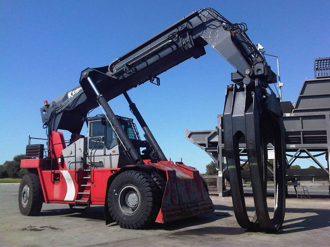
Terminal tractors KALMAR:
- KALMAR RTD 3026
- KALMAR TRX 182
- KALMAR TT 618i
- KALMAR TR 618i
- KALMAR TT 612d
Log loaders KALMAR:
- KALMAR RTD 1623
- KALMAR RTD 3026
Предложите, как улучшить StudyLib
(Для жалоб на нарушения авторских прав, используйте
другую форму
)
Ваш е-мэйл
Заполните, если хотите получить ответ
Оцените наш проект
1
2
3
4
5
Каталоги запасных частей, инструкции
по эксплуатации и ремонту погрузчиков KALMAR
|
|
|
|
|
|
|
|
|
|
|
|
|
|
|
|

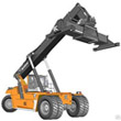

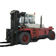
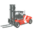
| N каталога |
Модель |
Наименование инструкции |
| KLM05-01 | DRD100-52 | Ричстакер KALMAR DRD100-52 Каталог запасных частей |
| KLM05-02 | DRD100-52 | Ричстакер KALMAR DRD100-52 Инструкция по эксплуатации |
| KLM05-03 | DRD100-52 | Ричстакер KALMAR DRD100-52 Инструкция по обслуживанию |
| KLM05-04 | DRD200-52 | Ричстакер KALMAR DRD200-52 Каталог запасных частей |
| KLM05-05 | DRD200-52 | Ричстакер KALMAR DRD200-52 Инструкция по эксплуатации |
| KLM05-06 | DRD200-52 | Ричстакер KALMAR DRD200-52 Инструкция по обслуживанию |
| KLM05-07 | DRD420-60 | Ричстакер KALMAR DRD420-60 C5 Каталог запасных частей |
| KLM05-08 | DRD420-60 | Ричстакер KALMAR DRD420-60 C5 Инструкция по эксплуатации |
| KLM05-09 | DRD420-60 | Ричстакер KALMAR DRD420-60 C5 Техническое описание |
| KLM05-10 | DRD420-60 | Ричстакер KALMAR DRD420-60 S5 Каталог запасных частей |
| KLM05-11 | DRD420-60 | Ричстакер KALMAR DRD420-60 S5 Инструкция по эксплуатации |
| KLM05-12 | DRD420-60 | Ричстакер KALMAR DRD420-60 S5 Инструкция по обслуживанию |
| KLM05-13 | DRD420-65 | Ричстакер KALMAR DRD420-65 C5 Каталог запасных частей |
| KLM05-14 | DRD420-65 | Ричстакер KALMAR DRD420-65 C5 Техническое описание |
| KLM05-15 | DRD420-65 | Ричстакер KALMAR DRD420-65 S5 Инструкция по обслуживанию |
| KLM05-16 | DRD420-70 | Ричстакер KALMAR DRD420-70 C6 Каталог запасных частей |
| KLM05-17 | DRD420-70 | Ричстакер KALMAR DRD420-70 C6 Инструкция по эксплуатации |
| KLM05-18 | DRD420-70 | Ричстакер KALMAR DRD420-70 C6 Техническое описание |
| KLM05-19 | DRD420-70 | Ричстакер KALMAR DRD420-70 S5, S6 Каталог запасных частей |
| KLM05-20 | DRD420-70 | Ричстакер KALMAR DRD420-70 S5 Инструкция по обслуживанию |
| KLM05-21 | DRD420-70 | Ричстакер KALMAR DRD420-70 S5, S6 Инструкция по эксплуатации |
| KLM05-22 | DRD450-60 | Ричстакер KALMAR DRD450-60 C5 Каталог запасных частей |
| KLM05-23 | DRD450-60 | Ричстакер KALMAR DRD450-60 C5, C5X Инструкция по эксплуатации |
| KLM05-24 | DRD450-60 | Ричстакер KALMAR DRD450-60 C5 Техническое описание |
| KLM05-25 | DRD450-60 | Ричстакер KALMAR DRD450-60 S5 Каталог запасных частей |
| KLM05-26 | DRD450-60 | Ричстакер KALMAR DRD450-60 S5, S5X Инструкция по эксплуатации |
| KLM05-27 | DRD450-60 | Ричстакер KALMAR DRD450-60 S5 Инструкция по обслуживанию |
| KLM05-28 | DRD450-65 | Ричстакер KALMAR DRD450-65 C5 Каталог запасных частей |
| KLM05-29 | DRD450-65 | Ричстакер KALMAR DRD450-65 C5 Техническое описание |
| KLM05-30 | DRD450-65 | Ричстакер KALMAR DRD450-65 S5 Инструкция по обслуживанию |
| KLM05-31 | DRD450-70 | Ричстакер KALMAR DRD450-70 C5 Каталог запасных частей |
| KLM05-32 | DRD450-70 | Ричстакер KALMAR DRD450-70 C5, C5X Инструкция по эксплуатации |
| KLM05-33 | DRD450-70 | Ричстакер KALMAR DRD450-70 C5 Техническое описание |
| KLM05-34 | DRD450-70 | Ричстакер KALMAR DRD450-70 S5 Каталог запасных частей |
| KLM05-35 | DRD450-70 | Ричстакер KALMAR DRD450-70 S5, S5X Инструкция по эксплуатации |
| KLM05-36 | DRD450-70 | Ричстакер KALMAR DRD450-70 S5 Инструкция по обслуживанию |
| KLM05-37 | DRD450-80 | Ричстакер KALMAR DRD450-80 C4, C5 Каталог запасных частей |
| KLM05-38 | DRD450-80 | Ричстакер KALMAR DRD450-80 C4X Инструкция по эксплуатации |
| KLM05-39 | DRD450-80 | Ричстакер KALMAR DRD450-80 C5 Техническое описание |
| KLM05-40 | DRD450-80 | Ричстакер KALMAR DRD450-80 S4, S5 Каталог запасных частей |
| KLM05-41 | DRD450-80 | Ричстакер KALMAR DRD450-80 S4X Инструкция по эксплуатации |
| KLM05-42 | DRD450-80 | Ричстакер KALMAR DRD450-80 S5 Инструкция по обслуживанию |
Some KALMAR Forklift Truck Service Manuals PDF, Spare Parts Catalogs, Wiring Diagrams & Error Codes DTC are above the page.
1921 State Aircraft Factory established in Helsinki (later to be renamed Valmet Ltd.)
Kalmar is currently the most popular brand of reach stackers. Kalmar Industries AB is a subsidiary of Cargotec Sweden AB, one of the world
leaders in loading equipment business. Kalmar reach stackers belong to a high price category.
At the same time, the reach stackers of the Swedish manufacturer are famous for their quality and ease of use, which makes them competitive and always popular for many years.
In 2007, the company joined the international holding Cargotec — an international logistics company that unites three brands: Kalmar, Hiab and MacGREGOR.
Kalmar offers loaders, reach stackers and cranes
Hiab — lifting equipment for installation on car chassis.
MacGREGOR — services for the design, production and service of shipboard devices for cargo handling.
Kalmar Forklifts, Reachstackers, Wheel Loader Workshop Manuals, Spare Parts Catalog, Error Codes List PDF free download
See also:
Kalmar Forklifts Workshop Manuals download
| Title | File Size | Download Links |
| Kalmar DRF KDU Training Presentation [PPT] | 250.5kb | Download |
| Contmaster 45 Tons Technical Information Container Handler [PDF] | 405.3kb | Download |
| Kalmar ContChamp Onderhoud DRD-GB DRD-S technical handbook [PDF] | 8.7Mb | Download |
| Kalmar DCD90-180 Technical Handbook [PDF] | 11.4Mb | Download |
| Kalmar DCE 90–180, DCE 70-32E3–70-35E4 2006 Workshop Manual [PDF] | 51.4Mb | Download |
| Kalmar DCE90-180, diesel forklift – technical information [PDF] | 747.2kb | Download |
| Kalmar DCF360-450CSG Toplift container handlers 36 – 45 tons [PDF] | 1017.7kb | Download |
| Kalmar DCG90-180Lift trucks 9 – 18 tones [PDF] | 726.9kb | Download |
| Kalmar DNG3196 [PDF] | 679.3kb | Download |
| Kalmar DRD 420 Schematic [PDF] | 1.1Mb | Download |
| Kalmar DRD-S Technical Handbook [PDF] | 8.7Mb | Download |
| KALMAR DRF 400-450 Maintenance Manual [PDF] | 16.7Mb | Download |
| Kalmar DRF 400-450 Workshop Manual [PDF] | 26.5Mb | Download |
| Kalmar DRF 400–450 Error Codes List [PDF] | 5.6Mb | Download |
| Kalmar DRF400-450C Reachstackers de 40 – 45 tonedalas [PDF] | 680.8kb | Download |
| Kalmar DRF420-450L Technical brochure [PDF] | 4.3Mb | Download |
| Kalmar DRF450 Workshop Manual [PDF] | 29.3Mb | Download |
| Kalmar DRT450 Reach Stacker Spec [PDF] | 3.8Mb | Download |
| Kalmar DRT450 VDRT02 / 02GB Reachstackers Workshop Manual [PDF] | 39.3Mb | Download |
| Kalmar Drt450 [PDF] | 906.9kb | Download |
| Kalmar montacargas DCE 90–180, DCE 70-32E3–70-35E Workshop Manual [PDF] | 51.4Mb | Download |
| Kalmar ReachStackers 42-45 t [PDF] | 635.4kb | Download |
| Kalmar Rs045xx Drf450 Service Manual [PDF] | 18Mb | Download |
| Kalmar RT240 Handler 6pp Web [PDF] | 407.2kb | Download |
| Kalmar RT240 Technical Brochure [PDF] | 1.8Mb | Download |
| Reach Stackers Kalmar [PDF] | 1.2Mb | Download |
Kalmar Forklifts Spare Parts Catalogs download
| Title | File Size | Download Links |
| Kalmar DC 9-16 Spare Parts Catalogue [PDF] | 17.3Mb | Download |
| Kalmar DCD 200-300 Parts Manual [PDF] | 15.4Mb | Download |
| Kalmar DCD250 Spare Parts Catalogue [PDF] | 15.4Mb | Download |
| Kalmar DRD 420-450 Spare Parts Catalogue [PDF] | 35Mb | Download |
| Kalmar DRS4527–S5 Spare Parts List [PDF] | 8.9Mb | Download |
| Kalmar Items [PDF] | 455.1kb | Download |
| Kalmar R70 spare parts book [PDF] | 8.6Mb | Download |
| KALMAR R70-60, 70, 80 Spare Parts Catalogue [PDF] | 8.6Mb | Download |
| Kalmar reach stacker parts [PDF] | 455.1kb | Download |
| LISTA PARTS CATALAGUE DRS 4527 KALMAR [PDF] | 8.9Mb | Download |
Kalmar Forklifts
Kalmar Industries AB is a Swedish manufacturer of machinery for loading and unloading.
The history of the formation and development of Kalmar, a well-known manufacturer of loading equipment, has already crossed a century-old frontier.
Kalmar has manufacturing plants in Sweden, Finland, the Netherlands, Malaysia, China and the United States, more than 10 own equipment sales companies and over 150 dealers in all parts of the globe.
1921 – State Aircraft Factory was established in Helsinki (later to be renamed Valmet Ltd.)
1940 – the creation of the first timber truck company
1949 – the first loader in Sweden
1953 – the first port crane
1955 – the creation of the first center of after-sales customer support
1959 – sale of the first loader to a sawmill located in Austria
1960 – the first side-loader and container loader were created
1973 – company name changed to Kalmar
1985 – Series production of reachstackers
1997 – the company focuses on the development of new container and heavy loaders, as well as terminal tractors
2007 – Kalmar becomes part of Cargotec holding.
As of today, the company’s line of equipment is represented by:
- bridge cranes
- log loaders
- front and forklift trucks
- reachstackers (container loaders)
- tractors, including terminal
- loggers.
Kalmar reachstackers are designed to handle small and medium sized containers. They are able to handle containers and trailers, as well as to perform loading and unloading work in an industrial environment.
Kalmar forklifts are machines with a load capacity from 5 to 52 tons. They are suitable for work in the port, in mining enterprises, in the woodworking industry, in the production of building materials, in the automotive industry.
The lineup of Kalmar
- Machines with a carrying capacity of 5–9 tons. They are equipped with hydrostatic transmissions, electric, gas or diesel engines, optionally equipped with three types of cabs.
- Equipment for working with loads of 9-18 tons. The machines are equipped with a hydraulic system, sensitive to the load, and a special double-rod device for the safe lifting of steel coils.
- Equipment with a carrying capacity of 20–50 tons. Machines with the function of fast lifting of loads, disk brakes with oil cooling and hydrodynamic transmission.
- The Kalmar loaders of the Ro-Ro series with a lifting capacity of 28 and 33 tons. A new generation of equipment that is more compact and sensitive to control than other models of the brand.
- Container handlers with a load capacity of 36–45 tons. Used for lifting and storing loaded containers. Model DCF360CSG is designed to work with four containers, models DCF410CSG and DCF450CSG are able to simultaneously move five containers.

Kalmar Contchamp DRD 450
The Kalmar loader is a machine designed for lifting heavy loads in demanding conditions. The models are equipped with Volvo and Cummins engines, as well as an electronic control system, with the help of which the operator controls the operation of the forklift truck, changes the speed of lifting and lowering the load, performs diagnostics of the equipment.
![]()
KALMAR Rich Truck Fault Codes DTC
Kalmar Rich Truck Fault Codes DTC
Kalmar Rich Truck Fault Codes DTC.pdf
Adobe Acrobat Document
169.1 KB
![]()
Kalmar DCE 90–180, DCE 70-32E3–70-35E4 Workshop Manual
Kalmar DCE 90–180, DCE 70-32E3–70-35E4 Workshop Manual
Kalmar DCE 90–180, DCE 70-32E3–70-35E4 W
Adobe Acrobat Document
36.2 MB
![]()
Kalmar DRF450-65A5X Workshop Manual
Kalmar DRF450-65A5X Werkstattbuch
Kalmar DRF450-65A5X Werkstattbuch.pdf
Adobe Acrobat Document
10.8 MB
![]()
Kalmar DCD 200-300 Spare Parts Catalog
Kalmar DCD 200-300 Spare Parts Catalog
Kalmar DCD 200-300 Spare Parts Catalog.p
Adobe Acrobat Document
4.4 MB
![]()
Kalmar DRS 4527–S5 Spare Parts Catalog
Kalmar DRS 4527–S5 Spare Parts Catalog
Kalmar DRS 4527–S5 Spare Parts Catalog.p
Adobe Acrobat Document
4.6 MB
![]()
Kalmar DRD 420 Schematics
Kalmar DRD 420 Schematics
Kalmar DRD 420 Schematics.pdf
Adobe Acrobat Document
763.5 KB
![]()
Kalmar DC 9-16 Spare Parts Catalog
Kalmar DC 9-16 Spare Parts Catalog
Kalmar DC 9-16 Spare Parts Catalog.pdf
Adobe Acrobat Document
6.0 MB
KALMAR Forklift Truck Service Manuals & Schematics PDF above the page — DRF, DCD, DCE, DRD, DC, DRS; Kalmar
Rich Truck Fault Codes DTC.
Kalmar has manufacturing plants in Sweden, Finland, the Netherlands, Malaysia, China and the USA, more than 10 in-house technology companies
and over 150 dealers.
In 2007, Kalmar Industries entered the international holding corporation Cargotec.
This is an international logistics company — a world leader in the market of equipment for handling and moving goods.
Cargotec combines three brands: Kalmar, Hiab and MacGregor.
Products manufactured under the Kalmar trademark are represented by a wide range of forklift trucks and gantry cranes designed for
operation in various conditions.
The Kalmar forklift truck is a machine that is focused on lifting heavy loads in difficult operating conditions.
Models are equipped with Volvo and Cummins engines, as well as an electronic control system, through which the operator monitors the work of the forklift truck,
changes the speed of lifting and lowering the load, performs diagnostics of the equipment.