- Manuals
- Brands
- Rosemount Manuals
- Measuring Instruments
- 1151
- Product manual
-
Bookmarks
Quick Links
LCD Meter
Product Manual
Analog
Bar Graph
Left Configuration Button
00809-0100-4691
Right Configuration Button
English
Rev. AA
Related Manuals for Rosemount 1151
Summary of Contents for Rosemount 1151
-
Page 1
00809-0100-4691 English Rev. AA LCD Meter Product Manual Analog Bar Graph Left Configuration Button Right Configuration Button… -
Page 2
The Rosemount ® LCD meter is designed to be used with the Rosemount Model 1151 Smart and Analog Pressure Transmitters, the Model 1144 Pressure Transmitter, the Model 751 Field Signal Indicator, the Model 444 Temperature Transmitter, and the Model 1135 Pressure-to-Current Converter. -
Page 3
Figure 1 shows the mounting hardware required to properly install the LCD meter on a transmitter or in the field signal indicator. This mounting hardware may also be used with the Rosemount universal (analog) meter. LCD METER CONFIGURATION The LCD meter may be configured to meet specific requirements by using the left and right configuration buttons located on the meter face as shown on the cover. -
Page 4
Remove the cover 1. Unscrew the retaining ring shown on the cover and lift the transparent cover off of the housing. Position the decimal point and select the meter function 2. Press the left and right configuration buttons simultaneously and release them immediately. 3. -
Page 5
numbers, press the right configuration button. Set the numbers between –999 and 9999. The sum of the 4 mA point and the span must not exceed 9999. 11. To store the information, press both configuration buttons simultaneously for two seconds. Note that the meter displays “—-”… -
Page 6
LCD METER SPECIFICATIONS Input Signal 4–20 mA dc. Meter Indication 4-digit LCD showing –999 to 9999. A 20-segment bar graph directly represents the 4–20 mA current. Digital Display Resolution 0.05% of range ±1 digit. Analog Bar Graph Resolution 1 mA or 5% of input range. Indication Accuracy 0.25% of range ±1 digit. -
Page 7
Input current < 3.5 mA: Display blank. Input current > 22.0 mA: Display flashes 112.5% of full scale value or 9999, whichever is less. Hazardous Locations Approved for use with Rosemount Models 444, 751, 1135, 1144, and 1151. Meter Size -inch diameter face with… -
Page 8
Rosemount Inc. 8200 Market Boulevard Chanhassen, MN 55317 USA Tel 1-800-999-9307 Telex 4310012 Fax (612) 949-7001 © Rosemount Inc. 1997. All rights reserved. http://www.rosemount.com ¢00809-0100-4691S¤ 00809-0100-4691, Rev. AA… -
Page 9
Mounting Screw into Housing Strap Washer Retaining Straps Mounting Screws Mounting Screw into Mounting Plate Terminal Screws (Mount into Transmitter “Test” Terminal Block) Mounting Plate Meter (Meter May Be Rotated in 90° Increments) Cover Bushing Cover Foam Spacer FIGURE 1. LCD Meter Exploded View.
00809-0100-4360
English
Rev. AA
Model 1151
Alphaline® Pressure
Transmitters

Product Manual
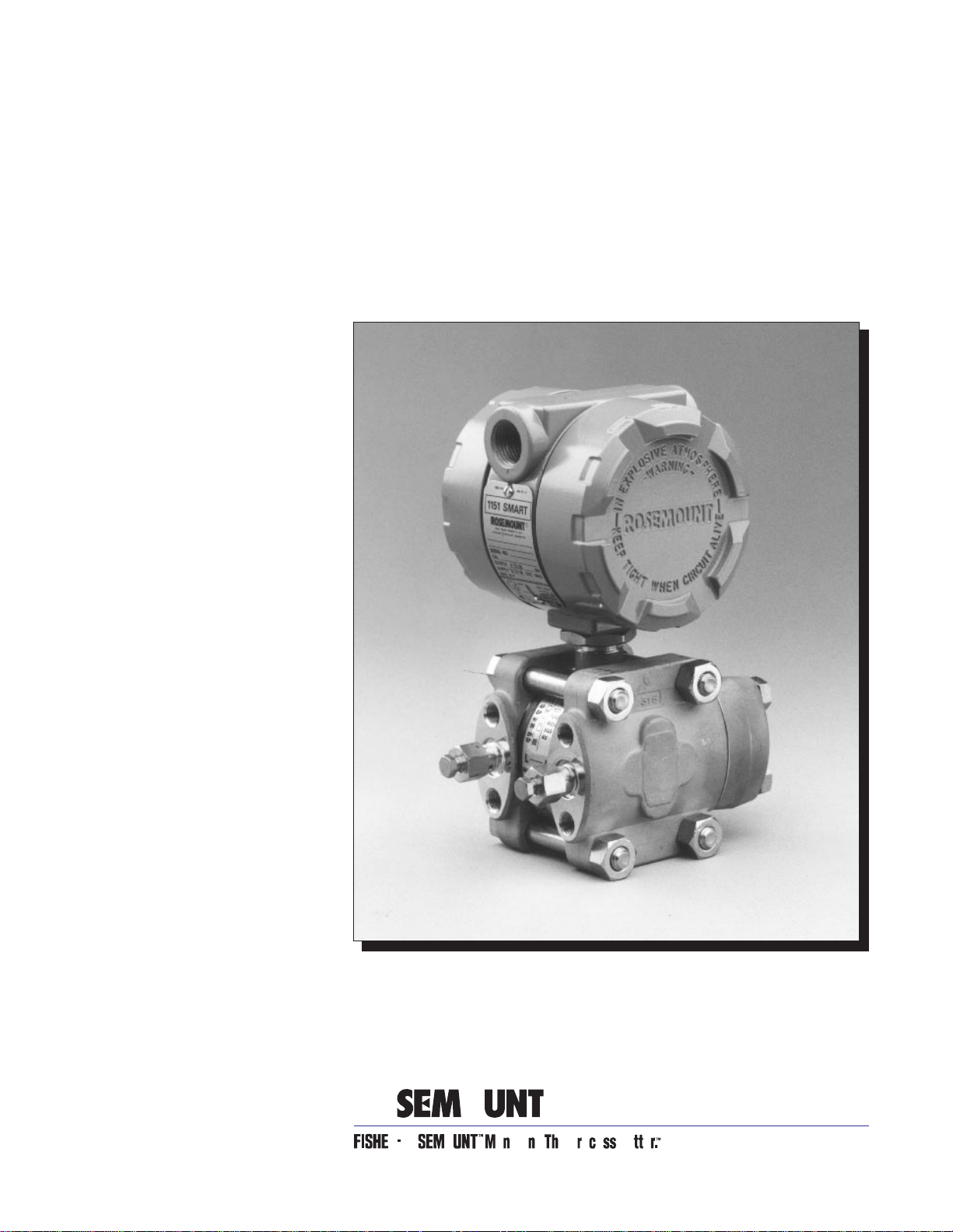
Model 1151 Alphaline® Pressure
Transmitters
NOTICE
Read this manual before working with the prod uc t. For perso nal and system
safety, and for optimum product performance, make sure you thoroughly
understand the conten ts before installing, using, or maintaining this product.
Within the United States, Rosemount Inc. ha s two tol l-free assistance numbers.
Customer Central: 1-800-999-9307 (
Technical support, quoting, and order-related questions.
North American 1-800-654-7768 (
Response Center: Equipment service needs.
For equipment s ervice or s upport n eeds outs ide th e United State s, cont act your
local Rosemount representative.
7:00 a.m. to 7:00 p.m. CST)
24 hours a day – Includes Canada)
Rosemount In c.
8200 Market Boulevard
Chanhassen, MN 55317 USA
Tel 1-800-999-9307
Telex 4310012
Fax (612) 949-7001
© 1997 Rosemount, Inc.
http://www.rosemount.com
The products described in this document are NOT designed for nuclearqualified applications.
Using non-nuclear qua lifi ed products in applications that require nuclearqualified hardware or products may cause inaccurate readings.
For information on Rosemount nucle ar-qualified products, contact you r local
Rosemount Sales Representative.
May be protected by one or more of the following U.S. Patent Nos. 3,195 ,028; 3,271,669; 3,318,15 3;
3,618,390; 3,646,538; 3,793,885; 3,800,413; 3,854,039; 3,859,594; 3,975,719; 4,339,750; 5,237,285;
Re. 30,603. May Depend on Model. Other U.S. and Foreign Patents Issued and Pending.
Rosemount, the Rosemount logotyp e, Alphaline, and SMART FAMILY are registered trademarks of
Rosemount Inc.
HART is a registered trademark of the HART Communication Foundation.
d
-Cell is a trademark of Rosemount Inc.
Hastelloy, Hastelloy C, and Hastelloy C-276 are registered trademarks of Cabot Corp.
Monel is a registered trademark of International Nickel Co.
Teflon is a registered trademark of E.I. du Pont de Nemours & Co.
Aflas is a registered trademark of Asahi Glass Co., Ltd.
Kynar is a trademark of Pennwalt Inc.
Flourolube is a registered trademark of Hooker Chemical Co.
Loctite is a registered trademark of Loctite Corporation.
Cover Photo: 1151-001AB
Fisher-Rosemount satisfies all obligations coming from legislation
to harmonize product requ ireme n ts in th e Euro pe a n Union.
T
N
I
E
D
R
P
IN
U.
A.
S.
SNF-0004


Table of Contents
Introduction
Installation
Using This Manua. . . . . . . . . . . . . . . . . . . . . . . . . . . . . . . . . . . . . . 9
Model 1151 Alphaline® Pressure Transmitters . . . . . . . . . . . . . . 9
Transmitter overview . . . . . . . . . . . . . . . . . . . . . . . . . . . . . . . . . . 10
General Considerations . . . . . . . . . . . . . . . . . . . . . . . . . . . . . . . . . 11
Mechanical Considerations. . . . . . . . . . . . . . . . . . . . . . . . . . . . . . . 11
Environmental Requirements . . . . . . . . . . . . . . . . . . . . . . . . . . . 13
Access Requirements . . . . . . . . . . . . . . . . . . . . . . . . . . . . . . . . 13
Process Flange Orientation . . . . . . . . . . . . . . . . . . . . . . . 13
Housing Rotation . . . . . . . . . . . . . . . . . . . . . . . . . . . . . . . . 13
Terminal Side of Electronics Housing . . . . . . . . . . . . . . . 13
Circuit Side of Electronics Housing . . . . . . . . . . . . . . . . . 13
Exterior of Electronics Housing . . . . . . . . . . . . . . . . . . . 13
Mounting Effects. . . . . . . . . . . . . . . . . . . . . . . . . . . . . . . . . . . 14
Process Connections . . . . . . . . . . . . . . . . . . . . . . . . . . . . . . . . 14
Mounting Brackets . . . . . . . . . . . . . . . . . . . . . . . . . . . . . . . . . 15
Mounting Requirements (for Steam, Liquid, Gas) . . . . . . . . 17
Taps . . . . . . . . . . . . . . . . . . . . . . . . . . . . . . . . . . . . . . . . . . 17
Drain/Vent Valves . . . . . . . . . . . . . . . . . . . . . . . . . . . . . . . 17
Impulse Piping . . . . . . . . . . . . . . . . . . . . . . . . . . . . . . . . . 18
Electrical Considerations . . . . . . . . . . . . . . . . . . . . . . . . . . . . . . . . 18
Wiring . . . . . . . . . . . . . . . . . . . . . . . . . . . . . . . . . . . . . . . . . . . 19
Conduit Sealing . . . . . . . . . . . . . . . . . . . . . . . . . . . . . . . . . . . 20
Power Supply . . . . . . . . . . . . . . . . . . . . . . . . . . . . . . . . . . . . . 20
Grounding . . . . . . . . . . . . . . . . . . . . . . . . . . . . . . . . . . . . . . . . 22
Signal Wiring . . . . . . . . . . . . . . . . . . . . . . . . . . . . . . . . . . . 22
Transmitter Case . . . . . . . . . . . . . . . . . . . . . . . . . . . . . . . 22
Grounding Effects . . . . . . . . . . . . . . . . . . . . . . . . . . . . . . . 22
Hazardous Locations Certifications. . . . . . . . . . . . . . . . . . . . 24
Liquid Level Measurement . . . . . . . . . . . . . . . . . . . . . . . . . . . . . . 24
Open Vessels . . . . . . . . . . . . . . . . . . . . . . . . . . . . . . . . . . . . . . 24
Closed Vessels . . . . . . . . . . . . . . . . . . . . . . . . . . . . . . . . . . . . . 24
Dry Leg Condition . . . . . . . . . . . . . . . . . . . . . . . . . . . . . . . 24
Wet Leg Condition . . . . . . . . . . . . . . . . . . . . . . . . . . . . . . . 25
Bubbler System in Open Vessel . . . . . . . . . . . . . . . . . . . . 26
Calibration
Quick Calibration Procedure (for E, G, and J Electronics). . . . . 29
Quick Calibration Procedure (For L and M Electronics) . . . . . . 29
Data Flow with Calibration Options . . . . . . . . . . . . . . . . . . . . . . 31
Span Adjustment Range . . . . . . . . . . . . . . . . . . . . . . . . . . . . . . . . 32
Zero Adjustment Range . . . . . . . . . . . . . . . . . . . . . . . . . . . . . . . . 32
Zero and Span Adjustment . . . . . . . . . . . . . . . . . . . . . . . . . . . . . . 34
Elevated or Suppressed Zeros . . . . . . . . . . . . . . . . . . . . . . . . . . . 35
Linearity Adjustment . . . . . . . . . . . . . . . . . . . . . . . . . . . . . . . . . . 35
Damping Adjustment . . . . . . . . . . . . . . . . . . . . . . . . . . . . . . . . . . 36
Static Pressure Span Correction Factor . . . . . . . . . . . . . . . . . . . . 37
i

Options
Mounting Brackets . . . . . . . . . . . . . . . . . . . . . . . . . . . . . . . . . . . . . 39
(Option Codes B1–B7 and B9) . . . . . . . . . . . . . . . . . . . . . 39
Analog Meters (4–20 ma only) . . . . . . . . . . . . . . . . . . . . . . . . . . . 41
LCD Meters (4–20 ma only) . . . . . . . . . . . . . . . . . . . . . . . . . . . . . 41
LCD Meter Configuration . . . . . . . . . . . . . . . . . . . . . . . . . . . 41
Remove the Cove . . . . . . . . . . . . . . . . . . . . . . . . . . . . . . .r 42
Position the Decimal Point and Select the Meter Function 42
Store the Information. . . . . . . . . . . . . . . . . . . . . . . . . . . . 43
Set the Display Equivalent to a 4 mA Signal . . . . . . . . . 43
Set the Display Equivalent to a 20 mA Signal. . . . . . . . 43
Replace the Cover. . . . . . . . . . . . . . . . . . . . . . . . . . . . . . . 43
LCD Meter Assembly . . . . . . . . . . . . . . . . . . . . . . . . . . . . . . . 43
LCD Meter Specifications . . . . . . . . . . . . . . . . . . . . . . . . . . . 44
Terminal Blocks. . . . . . . . . . . . . . . . . . . . . . . . . . . . . . . . . . . . . . . 45
Filter Terminal Block (Option Code R2) . . . . . . . . . . . . . . . . 46
Transient Protection and Filter Terminal Block
(Option Code R1) . . . . . . . . . . . . . . . . . . . . . . . . . . . . . . . . . . 46
Retrofitable Transient Terminal Block(Option Code R9). . . 46
R9 Terminal Block Installation . . . . . . . . . . . . . . . . . . . . 47
Terminal Block Specifications (for R1, R2, and R9) . . . . . . . 49
Maintenance and
Troubleshooting
Specifications and
Reference Data
Hardware Diagnostics. . . . . . . . . . . . . . . . . . . . . . . . . . . . . . . . . . 51
Transmitter Disassembly . . . . . . . . . . . . . . . . . . . . . . . . . . . . . . . 54
54
Process Sensor Body Removal 55
Removing the Sensor from the Electrical Housing . . . . 56
Sensor Module Checkout . . . . . . . . . . . . . . . . . . . . . . . . . 57
Reassembly Procedure . . . . . . . . . . . . . . . . . . . . . . . . . . . . . . . . . 58
Preliminary Precaution . . . . . . . . . . . . . . . . . . . . . . . . . . . . . 58
Connecting the Electrical Housing to the Sensor. . . . . . . . . 58
Backup Ring and O-ring Installation . . . . . . . . . . . . . . . . . . 58
Optional Plug-in Meter. . . . . . . . . . . . . . . . . . . . . . . . . . . . . .s 60
Return of Material . . . . . . . . . . . . . . . . . . . . . . . . . . . . . . . . . . . . 60
Functional Specifications . . . . . . . . . . . . . . . . . . . . . . . . . . . . . . . 61
Performance Specifications. . . . . . . . . . . . . . . . . . . . . . . . . . . . . . 66
Physical Specifications (Standard Configuration). . . . . . . . . . . . 68
ii

Section
1 Introduction
USING THIS MANUAL
This manual is designed to assist in installing, operating, and
maintaining the Rosemount Model 1151 Analog Pressure Transmitter
Family.
Section 2 Installation
provides mechanical and electrical installation instructions.
Section 3 Calibration
explains technique for calibration of the device.
Section 4 Options
explains the options available for the Model 1151, including mounting
brackets, LCD meters, custom configuration, transient protection, and
filter terminal blocks.
Section 5 Maintenance and Troubleshooting
describes trim procedures and offers troubleshooting instructions for
dealing with potential mechanical or electrical difficulties.
Section 6 Specifications and Reference Data
lists functional, performance, and physical specifications data as well
as ordering information for the transmitter.
Appendix A Approval Drawings
contains approval drawings for Canadian Standards Association (CSA)
and Factory Mutual (FM) intrinsic safety drawings.
Glossary
provides brief definitions of the terms use d in this manual and tells
where to find more information.
MODEL 1 151 ALPHALINE®
PRESSURE
TRANSMITTERS
Index
contains a comprehensive, standard index.
This manual describes the following Model 1151 Alphaline® Pressure
Transmitters.
• Model 1151DP— Differential Pressure Transmitter
measures differential pressure from 6 inH
(1.493 to 6895 kPa).
• Model 1151HP— Differential Pressure Transmitter
for High Line Pressures measures high line pressures from
25 inH
• Model 1151GP— Gage Pressure Transmitter
measures gage pressure from 6 inH
41369 kPa).
• Model 1151AP— Absolute Pressure Transmitter
measures absolute pressure from 25 inH
6895 kPa).
O to 300 psi (6.22 to 2668 kPa).
2
2
O to 6,000 psi (1.493 to
O to 1,000 psi
2
O to 1,000 psi (6.22 to
2
1-1

Model 1151 Alphaline® Pressure Transmitters
TRANSMITTER OVERVIEW
The Rosemount Model 1151 Alphaline® series of pressure transmitters
has set an industry standard as the largest-selling transmitter in the
world. It brings true precision to the measurement of flow, level, gage
and absolute pressures, vacuum, and specific gravity.
With proven performance, quality, and reliability, the Model 1151
provides accurate measurement using the variable capacitance
principle. It is virtually unaffected by changes in temperature, static
pressure, vibration, and power supply voltage.
Installation, calibration, and commissioning are simplified by the
transmitter’s compact design, integral junction box, and local span and
zero adjustments. Its modular design and high degree of
interchangeability result in a minimal investment for spare parts.
1-2

Section
2 Installation
This section covers areas to consider when installing the Model 1151
Analog Transmitter:
• General Considerations
• Mechanical Considerations
• Environmental Requirements
• Electrical Considerations
• Liquid Level Measurement
GENERAL
CONSIDERATIONS
MECHANICAL
CONSIDERATIONS
The accuracy of a flow, pressure, or level measurement depends on
proper installation of the transmitter and impulse piping. The piping
between the process and transmitter must accurately transmit process
pressure to the transmitter. Mount the transmitter close to the process
and use a minimum of piping to achieve best accuracy. Keep in mind,
however, the need for easy access, safety of personnel, practical field
calibration, and a suitable transmitter environment. In general, install
the transmitter so as to minimize vibration, shock, and temperature
fluctuations.
Installations in food, beverage, and pharmaceutical processes may
require sanitary seals and fittings. Regulations may dictate special
installation requirements needed to maintain sanitation and
cleanability considerations. See Product Data Sheet 00813-0100-4016
for more information about sanitary pressure instruments from
Rosemount Inc.
Rosemount Model 1151DP, GP, HP, and AP transmitters may be
mounted in several ways. They may be panel-mounted, wall-mounted,
or attached to a 2-inch pipe through an optional mounting bracket.
Figure 2-1 shows the transmitter dimensions. The following
paragraphs discuss factors necessary for a successful transmitter
installation.
2-1
Model 1151 Alphaline® Pressure Transmitters
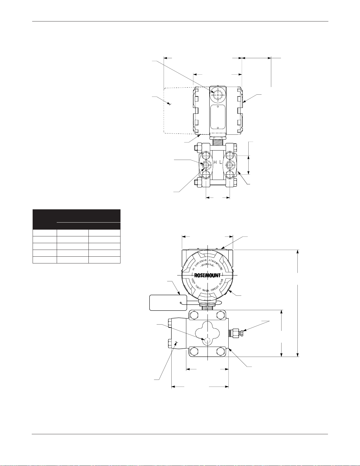
FIGURE 2-1. Dimensional Drawing
for Model 1151 Transmitter.
Flange Distance “A”
Range
3, 4, 5 2.125 54
6, 7 2.188 56
82.250 57
92.281 58
02.328 59
Center to Center
inches mm
½–14 NPT
Conduit
Connection
(2 Places)
Meter
Housing
Terminal Connections
This Side
¼–18 NPT on
Flanges for Pressure
Connection without
Flange Adapters
½–14 NPT on
Flange
Adapters
7.5 (191) Max.
with Optional Meter
4.5 (114)
Max.
A
(See Table)
4.5 (114)
Max.
0.75 (19)
Clearance for
Cover Removal
(Typical)
Transmitter
Circuitry
This Side
1.625
(41)
Blank Flange
Used on
AP and GP
Transmitters
Permanent
Tag (Optional)
NOTE
Dimensions are in inches (millimeters).
2-2
Wired-on
(Standard)
¼–18 NPT for
Side Drain/Vent
(Optional Top
or Bottom)
Flange
Adapter
Tag
4.5 (114)
3.375
(86)
9.0 (229) Max.
Nameplate
Drain/Vent
Valve
3.69
(94)
Flanges Can
Be Rotated
1151-1151A,B05A

Installation
ENVIRONMENTAL
REQUIREMENTS
Mount the transmitter to minimize ambient temperature changes. The
transmitter electronics temperature operating limits are –40 to 200 °F
(–40 to 85 °C) for “E” output options, –20 to 150 °F (–29 to 66 °C) for “J”
output options, and –20 to 200 °F (–29 to 93 °C) for G, L, and M output
options. Section 5 Maintenance and Troubleshooting lists the
sensing element operating limits. Mount the transmitter to avoid
vibration and mechanical shock, and to avoid external contact with
corrosive materials.
Access Requirements
When choosing an installation location and position, take into account
the need for access to the transmitter.
Process Flange Orientation Orient the process flanges to enable process connections to be made.
For safety reasons, orient the drain/vent valves so that process fluid is
directed down and away from technicians when the valves are used.
This can be accomplished by pointing the hole in the outside valve body
downward and away. In addition, consider the need for a testing or
calibration input.
Do not rotate the transmitter housing more than 90 degrees
without disconnecting the header board. Exceeding 90
degrees rotation will damage the internal sensor module
wiring. Refer to Removing the Sensor from the Electrical
Housing on page 5-6 for further information.
Housing Rotation The electronics housing may be rotated up to 90 degrees to improve
field access to the two housing compartments. T o rotate the housing less
than 90 degrees, loosen the housing lock nut and turn the housing not
more than 90 degrees from the orientation shown in Figure 2-1. To
rotate the housing more than 90 degrees, follow th e transmitter
disassembly procedures in Section 5 Maintenance and
Troubleshooting.
Terminal Side of
Electronics Housing
Make wiring connections through the conduit openings on the top side
of the housing. The terminal side of the housing is marked on the
nameplate located on the side of the transmitter. Mount the transmitter
so that the terminal side is accessible. A ¾-inch clearance is required
for cover removal with no meter. A 3-inch clearance is required for cover
removal if a meter is installed. If practical, provide approximately 6
inches clearance so that a meter may be installed later.
Circuit Side of
Electronics Housing
The circuit compartment should not routinely need to be opened when
the unit is in service; however, provide 6 inches clearance if possible to
allow access for on-site maintenance. The circuit side of the housing is
marked on the nameplate located on the side of the transmitter.
Exterior of Electronics Housing The analog Model 1151 uses local span and zero screws, which are
located under the nameplate on the side of the transmitter . Please allow
6 inches clearance if possible to allow access for on-site maintenance.
2-3
Model 1151 Alphaline® Pressure Transmitters
Mounting Effects
The analog Model 1151 weighs 12 lb (5.4 kg) for AP, DP, GP, and HP
transmitters, excluding options. This weight must be securely
supported; see Figure 2-2 on page 2-6 for mounting bracket
information. The transmitter is calibrated in an upright position at the
factory. If this orientation is changed during mounting, the zero point
will shift by an amount equivalent to the liquid head caused by the
mounting position. Zero and Span Adjustment on page 3-6 describes
how to correct this shift.
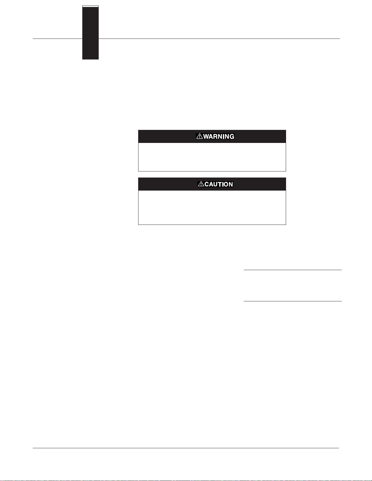
Process leaks can cause death or serious injury. Only use
bolts supplied with the transmitter or sold by Rosemount
Inc. as a spare part. Using unauthorized bolts may reduce
pressure retaining capabilities and render the instrum ent
dangerous.
Do not plug the low side with a solid plug. Plugging the low
side will cause an output shift.
Process Connections
Model 1151AP, DP, GP, and HP process connections on the transmitter
flanges are ¼–18 NPT. Flange adapter unions with ½–14 NPT
connections are supplied as standard. These are Class 2 threads; use
plant-approved lubricant or sealant when making the process
connections. The flange adapters allow users to disconnect from the
process by removing the flange adapter bolts. Figure 2-1 on page 2-2
shows the distance between pressure connections. This distance may be
1
varied ±
/8 inch (3.2 mm) by rotating one or both of the flange adapters.
To ensure a tight seal on the flange adapters or three-valve manifold,
first finger-tighten both bolts, then wrench-tighten the first bolt to
approximately 29 ft-lbs (34 Nm). Wrench-tighten the second bolt to
approximately 29 ft-lbs (34 Nm).
2-4
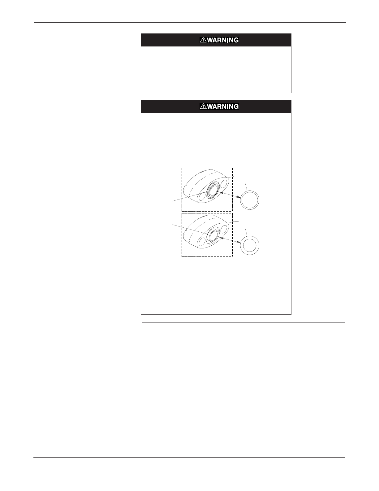
Process leaks can cause death or serious injury. Install and
tighten all four flange bolts before applying pressure, or
process leakage may result. When properly installed, the
flange bolts will protrude through the top of the module
housing. Attempting to remove the flange bolts while the
transmitter is in service may cause process fluid leaks.
Failure to install flange adapter O-rings can cause process
leaks, which can result in death or serious injury.
There are two styles of Rosemount flange adapters, each
requiring a unique O-ring, as shown below. Each flange
adapter is distinguished by its unique groove.
MODEL 3051/2024/3001/3095
Flange Adapter
O-ring
Installation
Unique O-ring
Grooves
Flange Adapter
O-ring
MODEL 1151
Use only the O-ring designed to seal with the corresponding
flange adapter.
Refer to the Spare Parts List on page 6-13 for the part
numbers of the flange adapters and O-rings designed for
the Model 1151 Pressure Transmitter.
NOTE
If Teflon O-rings are used, they should be replaced if the f lange adapter
is removed.
The low-side process flange has a ¼–18 NPT connection. A flange
adapter union is supplied for ½–14 NPT process connections. The
flange adapter allows the transmitter to be easily disconnected from the
process by removing the flange adapter bolts. On open vessels the lowside process flange is open to atmosphere and should be mounted with
the threaded hole pointed down. On closed vessels this connection is
used for the dry or wet leg.
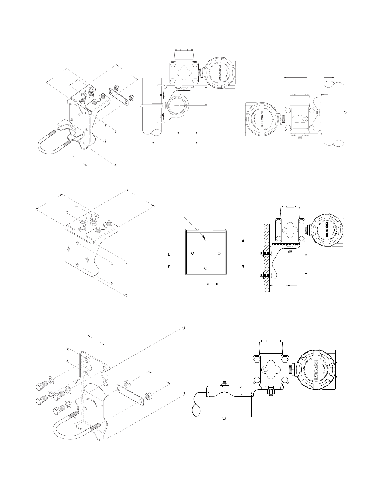
Mounting Brackets
An optional mounting bracket permits mounting the transmitter to a
wall, a panel, or a 2-inch horizontal or vertical pipe. Figure 2-2
illustrates some typical configurations using these mounting brackets.
2-5
Model 1151 Alphaline® Pressure Transmitters
FIGURE 2-2. Mounting Bracket
Options.
3.75
(95)
3.75 (95)
1.65 (42)
2.81
(71)
1.65 (42)
3.87
(98)
2.625 (67)
2.62
(67)
4.97
(127)
5.625
(143)
2.625
(67)
PIPE MOUNTING BRACKET OPTION CODES B1, B4, AND B7
3.87 (98)
Mounting Holes
0.375 Diameter
(10)
2.81 Typ.
(71)
1.40 (46)
2.81 Typ.
(71)
4.5 (114)
1.40
(36)
PANEL MOUNTING BRACKET OPTION CODES B2 AND B5
5.625
(143)
3051-3051D19A, 1151-1151D,B06C
2.81 Typ.
(71)
2.625
(67)
3051-3051B19A, 1151-0244A, 1151-1151E06A
2.125 (54)
1.62 (41)
NOTE
Dimensions are in inches (millimeters).
2-6
8 (203)
2.81 (71)
FLAT MOUNTING BRACKET OPTION CODES B3, B6, AND B9
3051-3051H19B, 1151-1151F06B
Installation
Mounting Requirements
The following information applies to steam, liquid, and gas installations.
(for Steam, Liquid, Gas)
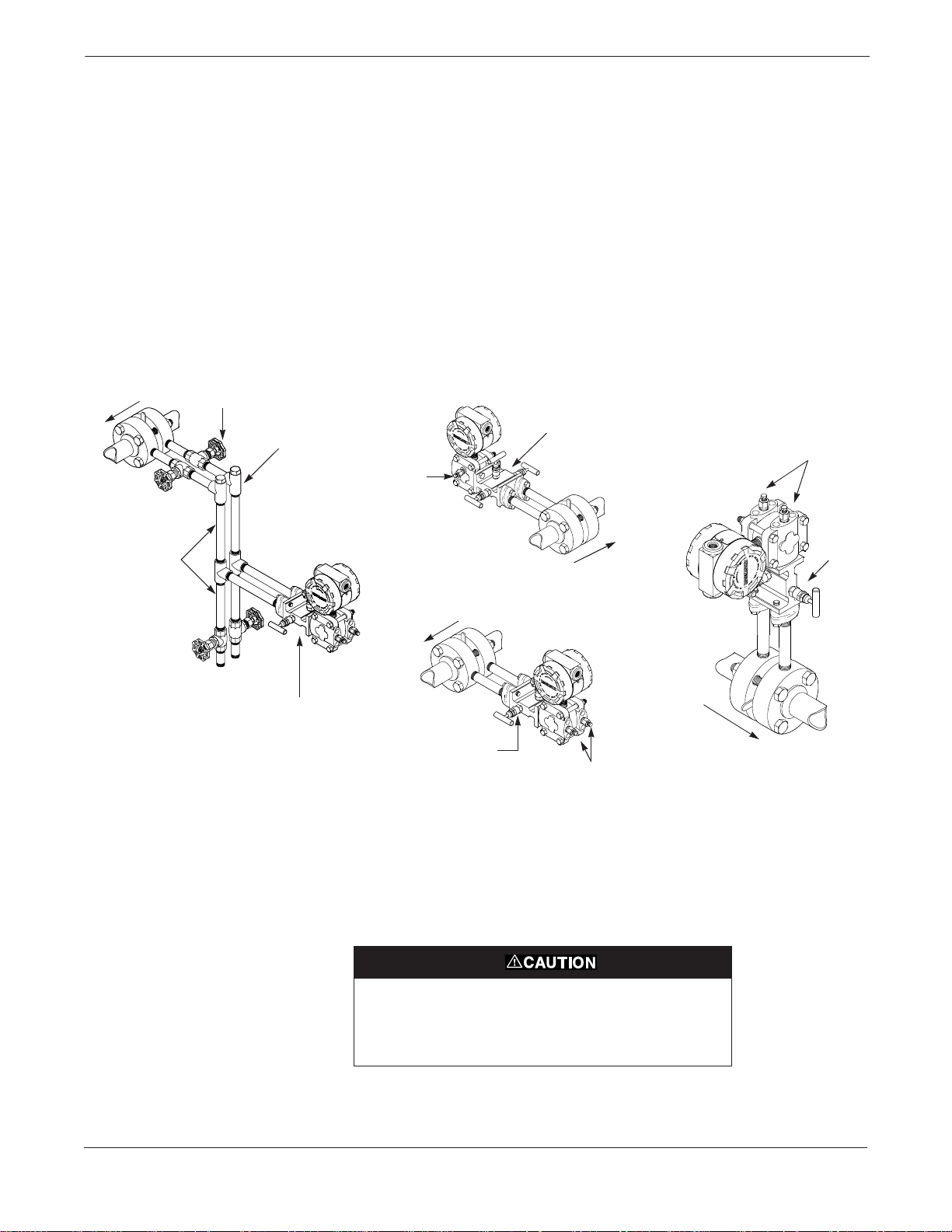
Taps Different measurement conditions call for different piping
configurations. For liquid flow measurement, place taps to the side of
the line to prevent sediment deposits, and mount the transmitter beside
or below these taps so gases can vent into the process line. For gas flow
measurement, place taps in the top or side of the line and mount the
transmitter beside or above the taps so liquid will drain into the process
line. For steam flow measurement, place taps to the side of the line with
the transmitter mounted below them to ensure that the impulse piping
stays filled with condensate. See Figure 2-3 for a diagram of these
arrangements.
FIGURE 2-3. Steam, Liquid, and
Gas Service Installation Diagrams.
Blocking
Flow
Valves
Plugged Tee
for Steam Service
for Sealing Fluid
Optional Side-
mounted Drain/
Vent Valve
LIQUID SERVICE
L
H
3-valve
Manifold
GAS SERVICE
H
Vent/Drain
Valve
L
Sufficient
Length for
Cooling
H
L
STEAM SERVICE
3-valve
Manifold
NOTE
For steam service do not blow down impulse piping
through transmitter. Flush lines with blocking valves closed
and refill lines with water before resuming measurement.
Flow
3-valve
Manifold
Flow
Flow
H
L
Drain/Vent
Valve
3-valve
Manifold
Drain/Vent Valves For transmitters with side drain/vent valves, place taps to the side of
the line. For liquid service, mount the side drain/vent valve upward to
allow the gases to vent. For gas service, mount the drain/vent valve
down to allow any accumulated liquid to drain. T o change the drain/vent
valve orientation from top to bottom, rotate the process flange 180
degrees.
1151-1151D,A,B,C01A
Steam or other elevated temperature processes can cause
damage to the sensor. Do not allow the temperature inside
the process flanges to exceed the transmitter limit of 220 °F
(104 °C).
In steam service, lines should be filled with water to prevent contact of
the live steam with the transmitter.
2-7

Model 1151 Alphaline® Pressure Transmitters
Impulse Piping The piping between the process and the transmitter must accurately
transfer the pressure in order to obtain accurate measurements. In this
pressure transfer , there are five possible sources of error: leaks, friction
loss (particularly if purging is used), trapped gas in a liquid line, liquid
in a gas line, and temperature-induced or other density variation
between the legs.
The best location for the transmitter in relation to the process pipe
depends on the process itself. Co nsider th e f ollowing gene ral guidelines
in determining transmitter location and placement of impulse piping:
• Keep impulse piping as short as possible.
• Slope the impulse piping at least 1 inch per foot (8 centimeters
per meter) upward from the transmitter toward the process
connection for liquid.
• Slope the impulse piping at least 1 inch per foot (8 centimeters
per meter) downward from the transmitter toward the process
connection for gas.
• Avoid high points in liquid lines and low points in gas lines.
• Make sure both impulse legs are the same temperature.
• Use impulse piping large enough to avoid friction effects and
prevent blockage.
• Vent all gas from liquid piping legs.
• When using a sealing fluid, fill both piping legs to the same level.
• When purging is necessary, make the purge connection close to
the process taps and purge through equal lengths of the same size
pipe. Avoid purging through the transmitter.
• Keep corrosive or hot process material out of direct contact with
the sensor module and flanges.
• Prevent sediment deposits in the impulse piping.
• Keep the liquid head balanced on both legs of the impulse piping.
ELECTRICAL
CONSIDERATIONS
2-8
Before making any electrical connections to the Model 1151 analog,
consider the following standards and be sure to have proper power
supply, conduit, and other accessories. Make sure all electrical
installation is in accordance with national and local code requirements,
such as the NEC (NFPA 70).
Explosions can cause death or serious injury. Do not
remove the instrument cover in explosive atmospheres
when the circuit is alive.
Do not connect the power signal wiring to the test terminals.
Voltage may burn out the reverse-polarity protection diode
in the test connection. If the test diode is destroyed, then the
transmitter can still be operated without local indication by
jumping the test terminals.
High voltage (greater than 55 Volts for “E” electronics, 85
Volts for “G” electronics, 12 Volts for “L” electronics, and 14
Volts for “M” electronics.) can cause damage to the
transmitter. Do not apply high voltage to the test terminals.
Installation
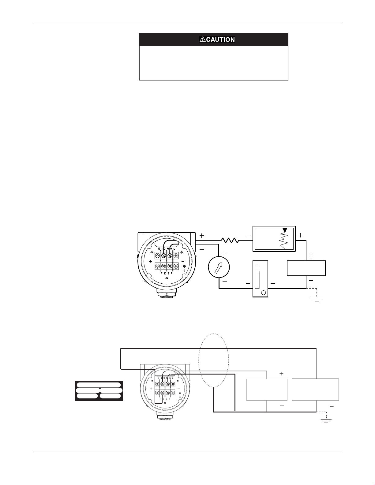
Wiring
FIGURE 2-4. Terminal Connections.
The signal terminals and test terminals are located in a compartment
of the electronics housing separate from the transmitter electronics.
The nameplate on the side of the transmitter indicates the locations of
the terminal and electronics compartments. The upper pair of
terminals are the signal terminals and the lower pair are the test
terminals. The test terminals have the same 4–20 mA output as the
signal terminals and are only for use with the optional integral meter
or for testing.
To make connections, remove the cover on the side marked “Terminal”
on the nameplate. All power to the transmitter is supplied over the
signal wiring. Connect the lead that originates at the positive side of
the power supply to the terminal marked “+” and the lead that
originates at the negative side of the power supply to the terminal
marked “–” as shown in Figure 2-4. No additional wiring is required.
Shielded cable should be used for best results in electrically noisy
environments.
POWER
SUPPL Y
FIGURE 2-5. Wiring Con nec tions for
Low Power Output Codes L and M.
Terminal
+
Common
Case
+ Power
Signal
Field Wiring
Label Detail
The signal loop may be grounded at
any point or left ungrounded.
Shield
Supply
Power
1151-1151G05A
A to D
Converter
1151-1151H05A
2-9
Model 1151 Alphaline® Pressure Transmitters
NOTE
An alternate location to connect an ammeter is on the set of terminals
labelled “TEST.” Connect the positive lead of the ammeter to the
positive test terminal, and the negative lead of the ammeter to the
negative test terminal.
NOTE
When conduit lines are used, signal wiring need not be shielded, but
twisted pairs should be used for best results. Wiring should be 12-24
AWG.
Conduit Sealing
Power Supply
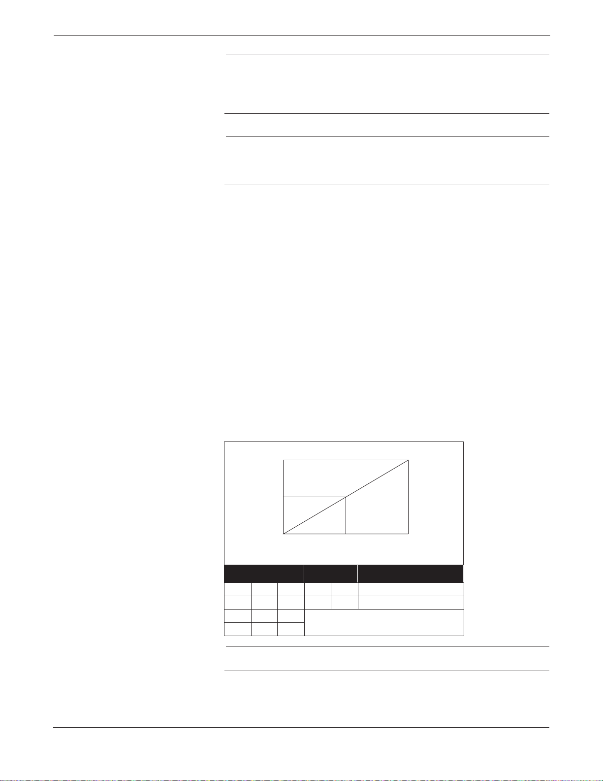
FIGURE 2-6. Power Supply Load
Limitations.
The 1151 has been rated as “Factory Sealed” by Factory Mutual (FM)
and Canadian Standards Association (CSA). It is therefore not
necessary to install conduit seals near the transmitter enclosure.
Do not run signal wiring in conduit or open trays with power wiring, or
near heavy electrical equipment. Signal wiring may be grounded at any
one point on the signal loop, or it may be left ung rounde d. The n egative
terminal of the power supply is a recommended grounding point. The
transmitter case must be grounded through the process or conduit
connections.
The dc power supply should provide power with less than 2 percent
ripple. The total resistance load is the sum of the resistance of the
signal leads and the load resistance of the controller, indicator, and
related pieces. Note that the resistance of intrinsic safety barriers, if
used, must be included.
To power the loop, connect the leads at the set of terminal screws
labeled “Signal.” Figure 2-6 illustrates power supply load limitations
for the transmitter:
R
max
2-10
R
L
R
min
V
min
Code V
E, J 12 45 0 1650 RL = 50 (VS – 12)
G 30 85 0 1100 R
L512
M814
minVmaxRminRmaxRL
Low Power Minimum Load Impedance:
V
S
Operating
Region
V
max
at Supply Voltage (VS)
= 20 (VS – 30)
L
100 kV
NOTE
For CSA Approvals (codes E and J), V
= 42.4 V dc.
max
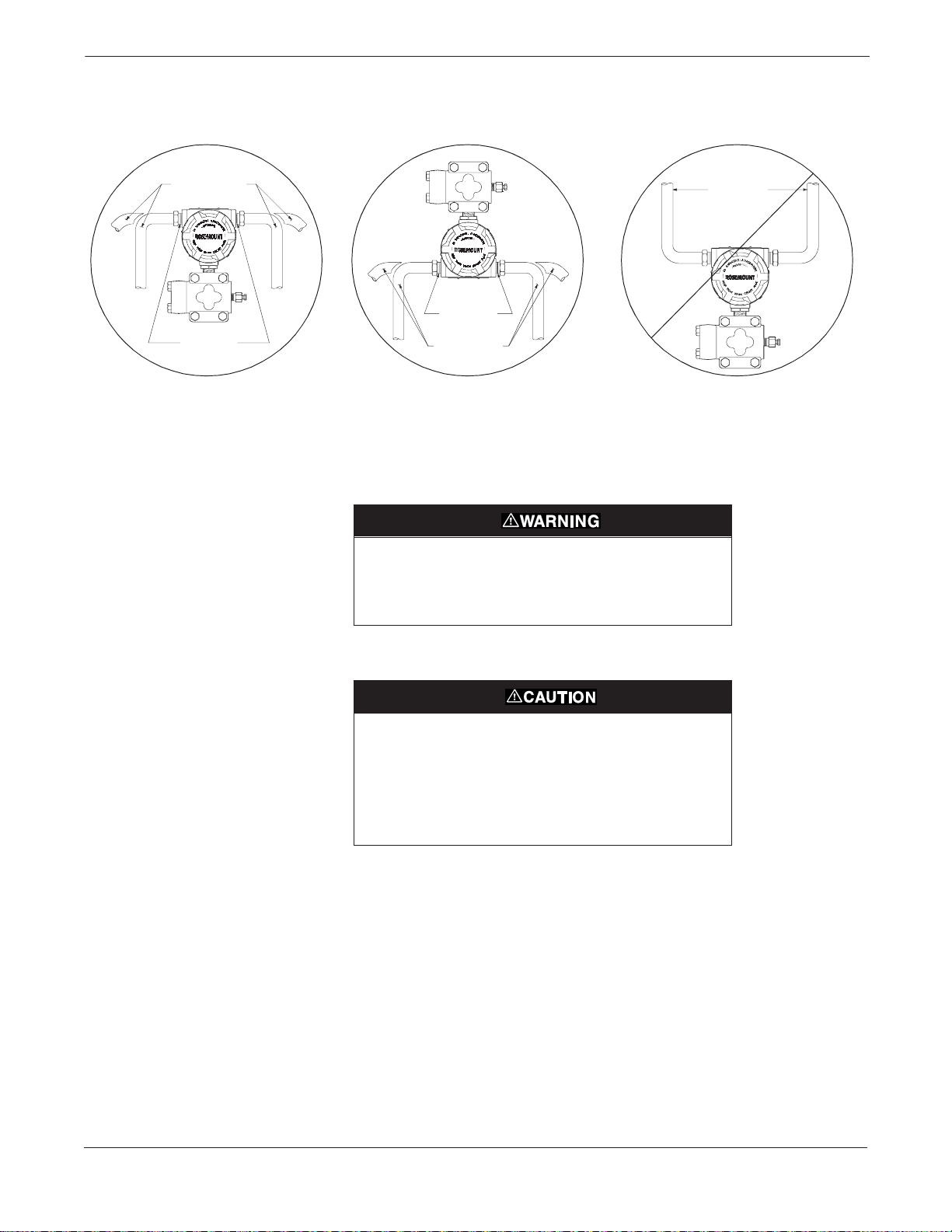
FIGURE 2-7. Conduit Installat ion
Diagrams.
Installation
Possible
Conduit Line
Positions
1151-1 151D25A
Sealing
Compound
CORRECT CORRECT INCORRECT
Sealing
Compound
Possible
Conduit Line
Positions
1151-1151E25A
Conduit
Lines
Unused conduit connections on the transmitter housing should be
plugged and sealed to avoid moisture accumulation in the terminal side
of the housing. The recommended connections of conduit are shown in
Figure 2-7.
All explosion proof, flameproof, and dust-ign ition proof
installations require insertion of conduit plugs in all unused
openings with a minimum of 40 ft-lbs (54 N-m) of torque.
This will maintain five full threads of engagement.
1151-1151F25A
If all connections are not sealed, excess moisture
accumulation can damage the transmitter. Make sure to
mount the transmitter with the electrical housing positioned
downward for drainage. To avoid moisture accumulation in
the housing, install wiring with a drip loop, and ensure the
bottom of the drip loop is mounted lower than the conduit
connections or the transmitter housing.
Grounding
Use the following techniques to properly ground the transmitter signal
wiring and case:
Signal Wiring Do not run signal wiring in conduit or open trays with power wiring, or
near heavy electrical equipment. Signal wiring may be grounded at any
one point on the signal loop, or it may be left ung rounde d. The n egative
terminal of the power supply is a recommended grounding point.
Transmitter Case The transmitter case must be grounded in accordance with national
and local electrical codes. The most effective transmitter case
grounding method is a direct internal connection to earth ground with
minimal impedance.
2-11

Model 1151 Alphaline® Pressure Transmitters
Internal Ground Connection: Inside the FIELD TERMINALS side of
the electronics housing is the Internal Ground Connection screw. This
screw is identified by a ground symbol: .
NOTE
Grounding the transmitter case via threaded conduit connection may
not provide sufficient ground continuity.
NOTE
The transient protection terminal block (See Figure 4-4 on page 4-8)
does not provide transient protection unless the transmitter case is
properly grounded. Use the preceding guidelines to ground the
transmitter case.
Do not run the transient protection ground wire with signal wiring as
the ground wire may carry excessive current if a lightning strike occurs.
Grounding Effects The capacitance sensing module requires alternating current to
generate a capacitance signal. This alternating current is developed in
an oscillator circuit with a frequency of approximately 32 kHz. This
signal is capacitor-coupled to transmitter-case ground through the
sensing module. Because of this coupling, a voltage may be imposed
across the load, depending on the choice of grounding. See Figure 2-8.
Hazardous Locations
Certifications
This impressed voltage, which is seen as high frequency noise, will have
no effect on most instruments. Computers with short sampling times
will detect a significant noise signal, which should be filtered out by
using a large capacitor (1 µF) or by using a 32 kHz LC filter across the
load. Computers are negligibly affected by this noise and do not need
filtering
The Model 1151 was designed with an explosion-proof housing and
circuitry suitable for intrinsically safe and non-incendive operation.
Factory Mutual explosion-proof certification is standard for the Model
1151 Transmitter. Individual transmitters are clearly marked with a
tag indicating the approvals they carry. Transmitters must be installed
in accordance with all applicable codes and standards to maintain these
certified ratings. Refer to Hazardous Locations Certifications on
page 6-2 for information on the approvals associated with the analog
Model 1151.
.
2-12
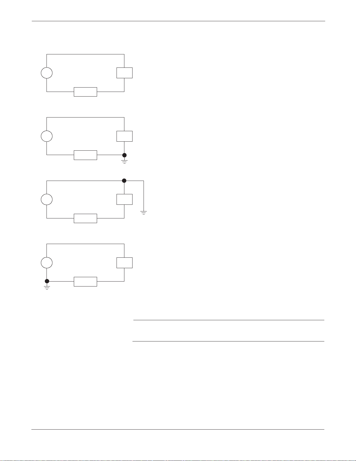
FIGURE 2-8. T ypic al Ef fe ct s of Groundi ng
on Accuracy for Fast Sample Computers
(4-20 mA loops only).
Installation
PT
PT
PT
LOAD
LOAD
LOAD
+
PS
–
+
PS
Ungrounded System
Impressed Voltage: 12 to 22 mVp-p
32 kHz
Effect: 0.01% of span.
Ground Between Negative Sid e of Power Sup ply an d Load
Impressed Voltage: 35 to 60 mVp-p
32 kHz
Effect: 0.03% of span.
–
+
PS
–
Ground Between Positive Sid e of Transmitter and Power Supply
Impressed Voltage: 35 to 60 mVp-p
32 kHz
Effect: 0.03% of span.
PT
LOAD
+
PS
–
Ground Between Negative Terminal of Transmitter and Load
Impressed Voltage: 500 to 600 mVp-p
32 kHz
Effect: 0.27% of span.
NOTE
Typical effects caused by the impressed voltage on a computer with a
sampling time of 100 microseconds using a 2 to 10 volt signal.
2-13
Model 1151 Alphaline® Pressure Transmitters
LIQUID LEVEL
MEASUREMENT
Open Vessels
Closed Vessels
Differential pressure transmitters used for liquid level applications
measure hydrostatic pressure head. Liquid level and specific gravity of
a liquid are factors in determining pressure head. This pressure is
equal to the liquid height above the tap multiplied by the specific
gravity of the liquid. Pressure head is independent of volume or vessel
shape.
A pressure transmitter mounted near a tank bottom measures the
pressure of the liquid above.
Make a connection to the high pressure side of the transmitter, and
vent the low pressure side to the atmosphere. Pressure head e quals the
liquid’s specific gravity multiplied by the liquid height above the tap.
Zero range suppression is required if the transmitter lies below the zero
point of the desired level range. Figure 2-9 shows a liquid level
measurement example.
Pressure above a liquid affects the pressure measured at the bottom of
a closed vessel. The liquid specific gravity multiplied by the liquid
height plus the vessel pressure equals the pressure at the bottom of the
vessel.
To measure true level, the vessel pressure must be subtracted from the
vessel bottom pressure. T o do this, make a pressure tap at the top of the
vessel and connect this to the low side of the transmitter. Vessel
pressure is then equally applied to both the high and low sides of the
transmitter . The resulting diff eren tial pressure is pro portional to liquid
height multiplied by the liquid specific gravity.
Dry Leg Condition Low-side transmitter piping will remain empty if gas above the liquid
does not condense. This is a dry leg condition. Range determination
calculations are the same as those described for bottom-mounted
transmitters in open vessels, as shown in Figure 2-9.
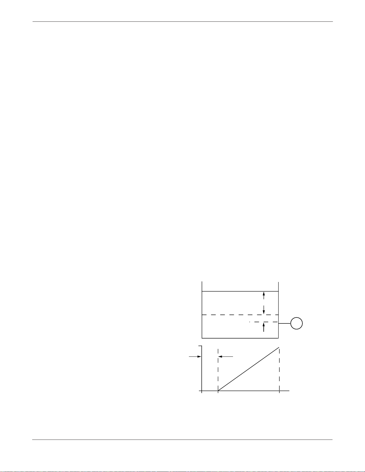
FIGURE 2-9. Liquid Level
Measurement Example.
X
Let X equal the vertical distance between the minimum and maximum
measurable levels (500 in.).
Let Y equal the vertical distance between the transmitter datum line and the
minimum measurable level (100 in.).
Let SG equal the specific gravity of the fluid (0.9).
Let h equal the maximum head pressure to be measured in inches of water.
Let e equal head pressure produced by Y expressed in inches of water.
Let Range equal e to e + h.
Then h = (X)(SG)
= 500 x 0.9
= 450 inH
e=(Y)(SG)
= 100 x 0.9
= 90 inH
Range = 90 to 540 inH
O
2
O
2
O
2
20
mA dc
ZERO
4
SUPPRESION
900
inH2O
Y
T
540
2024-0171A, 0172A
2-14
Installation
Wet Leg Condition Condensation of the gas above the liquid slowly causes the low side of
the transmitter piping to fill with liquid. The pipe is purposely filled
with a convenient reference fluid to eliminate this potential error. This
is a wet leg condition.
The reference fluid will exert a head pressure on the low side of the
transmitter . Z ero elevatio n of the range must then be made. See Figure
2-10.
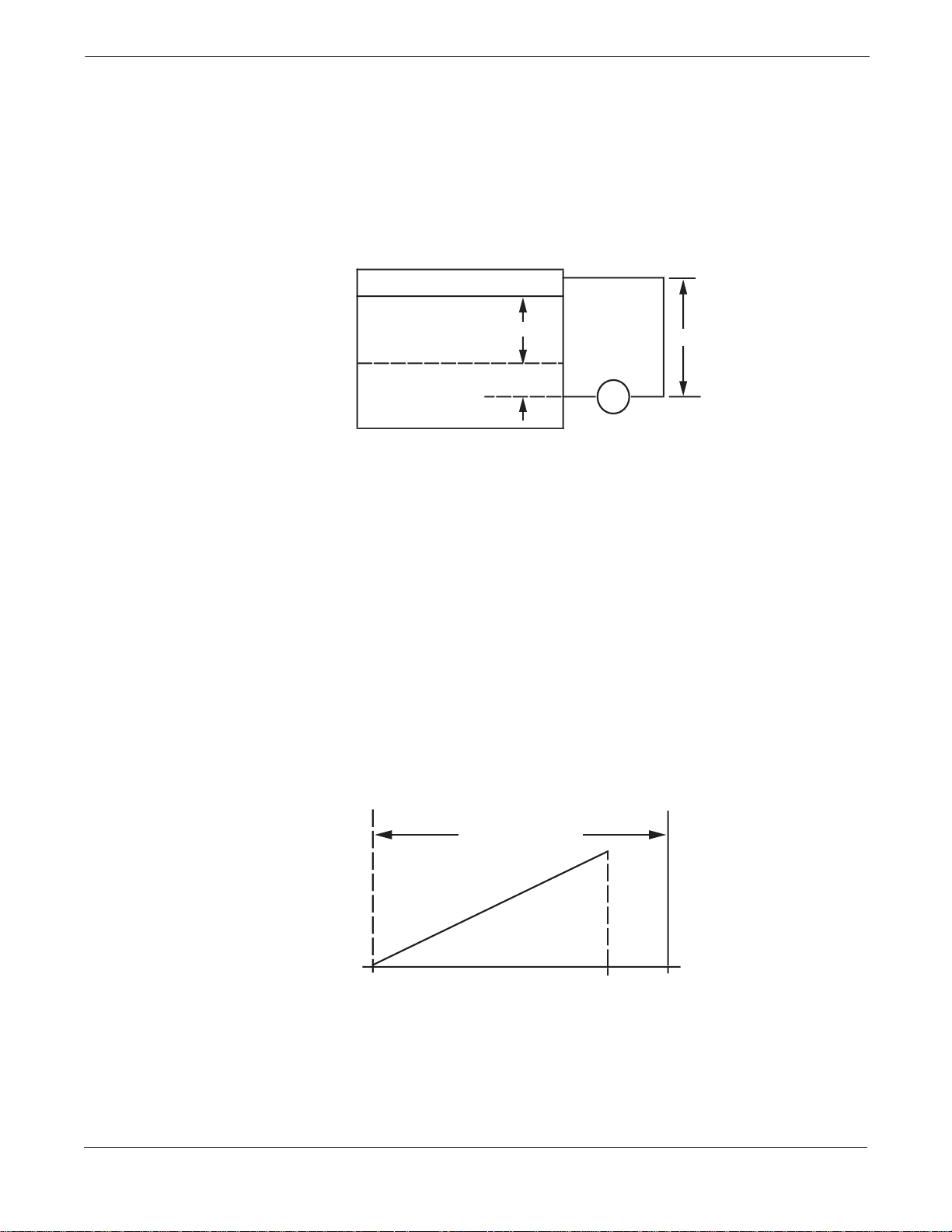
FIGURE 2-10. Wet Leg Example.
X
Y
LT
Z
H L
Let X equal the vertical distance betwe en the minimum and max im um
measurable levels (500 in.).
Let Y equal the vertical distance between the transmitter datum line and the
minimum measurable level (50 in.).
Let z equal the vertical distance between the top of the liquid in the wet leg
and the transmitter datum line (600 in.).
Let SG
equal the specific gravity of the fluid (1.0).
1
Let SG
equal the specific gravity of the fluid in the wet leg (1.1).
2
Let h equal the maximum head pressure to be measured in inches of water.
Let e equal the head pressure produced by Y expressed in inches of water.
Let s equal head pressure produced by z expressed in inches of water.
Let Range equal e – s to h + e – s.
Then h = (X)(SG
= 500 x 1.0
= 500 in H
e=(Y)(SG
= 50 x 1.0
= 50 inH
s=(z)(SG
= 600 x 1.1
= 660 inH
Range = e – s to h + e – s.
= 50 – 660 to 500 + 50 – 660
= –610 to –110 inH
)
1
O
2
)
1
O
2
)
2
0
2
0
2
ZERO ELEVATION
inH2O
20
mA dc
4
-110-610
0
2024-0167A 2024-0168A
2-15
Model 1151 Alphaline® Pressure Transmitters
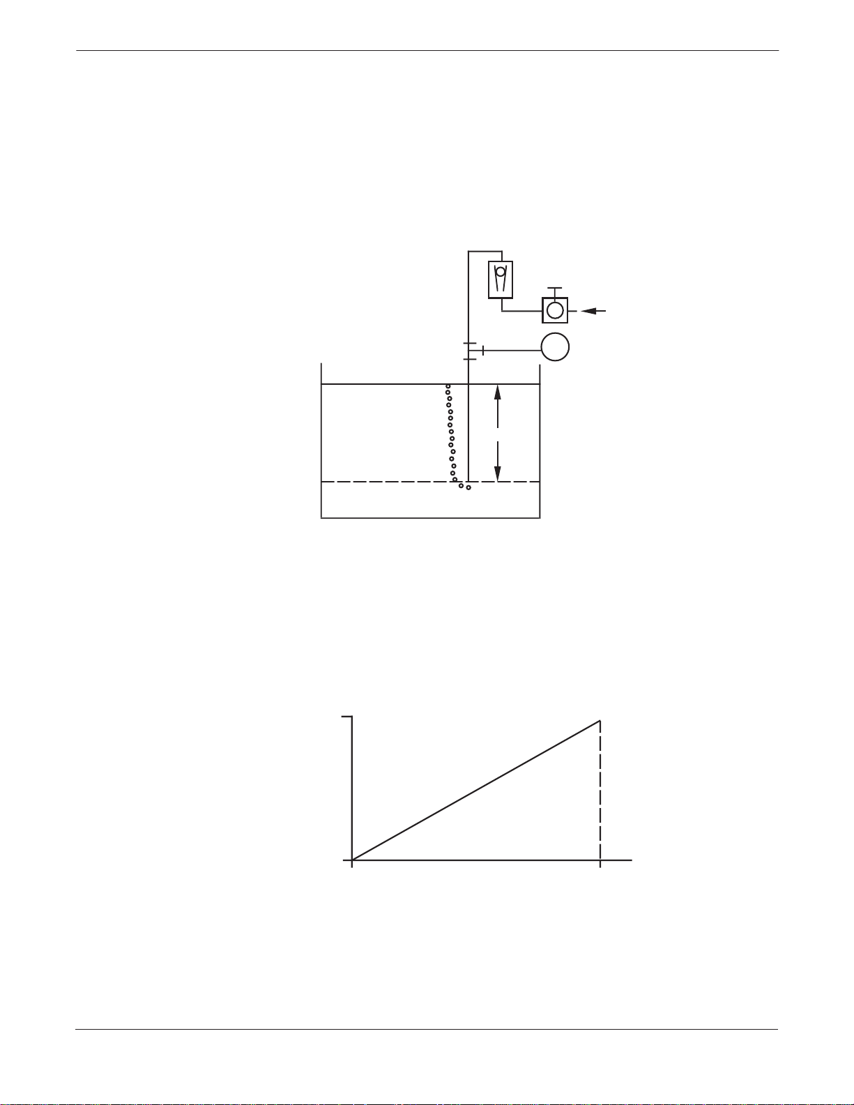
Bubbler System in Open Vessel A bubbler system that has a top-mounted pressure transmitter can be
used in open vessels. This system consists of an air supply, pressure
regulator, constant flow meter, pressure transmitter, and a tube that
extends down into the vessel.
Bubble air through the tube at a constant flow rate. The pressure
required to maintain flow equals the liquid’s specific gravity multiplied
by the vertical height of the liquid above the tube opening. Figure 2-11
shows a bubbler liquid level measurement example.
FIGURE 2-11. Bubbler Liquid Level
Measurement Example.
AIR
T
X
Let X equal the vertical distance betwe en the minimum and max im um
measurable levels (100 in.).
Let SG equal the specific gravity of the fluid (1.1).
Let h equal the maximum head pressure to be measured in inches of water.
Let Range equal zero to h.
Then h = (X)(SG)
= 100 x 1.1
= 110 inH
Range = 0 to 110 inH
20
mA dc
4
0
O
2
O
2
110
inH2O
2024-0165A
2024-0166A
2-16
Section
3 Calibration
Calibration of the Rosemount Model 1151 Pressure Transmitter is
simplified by its compact and explosion-proof design, external span and
zero adjustments, separate compartments for electronics and wiring,
and weatherproof construction. Descriptions of span, linearity, zero
adjustments, and damping follow.
Explosions can cause death or serious injury. Both
transmitter covers must be fully engaged to meet explosionproof requirements.
When replacing housing covers, tighten the covers enough
to make contact with the O-ring seals. If the covers are not
tightened enough, moisture can enter the housing and
cause transmitter failure.
QUICK CALIBRATION
PROCEDURE (FOR E, G,
AND J ELECTRONICS)
QUICK CALIBRATION
PROCEDURE (FOR L AND
M ELECTRONICS)
The following Quick Calibration Procedures are for those users who are
already familiar with the analog Model 1151.
NOTE
The zero and span adjustments are interactive. For applications
requiring large elevated or suppressed values, refer to Elevated or
Suppressed Zeros on page 3-7.
1. Apply 4 mA-point pressure and turn zero screw to output 4 mA.
2. Apply 20 mA-point pressure.
3. Subtract actual output from desired output.
4. Divide difference by 3.
5. Turn span screw above or below desired output by value in Step 4.
6. Repeat Steps 1 through 5 until calibrated.
1. Apply 1 V dc-point pressure for M electronics (0.8 V dc for L electronics)
and turn zero screw to output 1 V dc (0.8 V dc for L electronics).
2. Apply 5 V dc-point pressure (M electronics) or 3.2 V dc (L electronics).
3. Subtract actual output from desired output.
4. Divide difference by 3.
5. Turn span screw above or below desired output by value in Step 4.
6. Repeat Steps 1 through 5 until calibrated.
3-1

Model 1151 Alphaline® Pressure Transmitters
Example for a Model 1151DP Range 4: For a desired calibration of 0
to 100 inH
1. Adjust the zero. With zero input applied to the transmitter, turn
the zero adjustment screw until the transmitter reads 4 mA.
2. Adjust the span. Apply 100 inH
connection. Turn the span adjustment screw until the transmitter
output reads approximately 20 mA.
3. Release the input pressure and readjust the zero output to read 4
mA ±0.032 mA.
4. Re-apply 100 inH
greater than 20 mA, divide the difference by 3, and subtract the
result from 20 mA. Adjust the 100% output to this value.
If the output reading is less than 20 mA, divide the difference by 3 and
add the result to 20 mA. Adjust the 100% output to this value.
Example: The full scale transmitter output is 20.100 mA. Dividing
0.100 by 3.0 gives the product 0.033. Subtracting the product 0.033
from 20.00 mA gives the difference 19.967 mA. Adjust the 100% output
to this value.
5. Release input pressure and readjust the zero.
6. Apply 100% input and repeat Steps 3 through 5 if the full scale
output is not 20 ±0.032 mA.
O, use the following procedure:
2
O to the transmitter high side
2
O to the transmitter. If the output reading is
2
NOTE
Under operating conditions that subject the transmitter to temperature
extremes or significant vibration, mechanical backlash may occur in the
zero and span adjustment screws. To improve the stability of zero and
span settings in these circumstances, back off the adjustment screws
slightly after final adjustment to break contact between the
potentiometer blades and the adjustment screw slot surfaces.
3-2
Calibration
DATA FLOW WITH
CALIBRATION OPTIONS
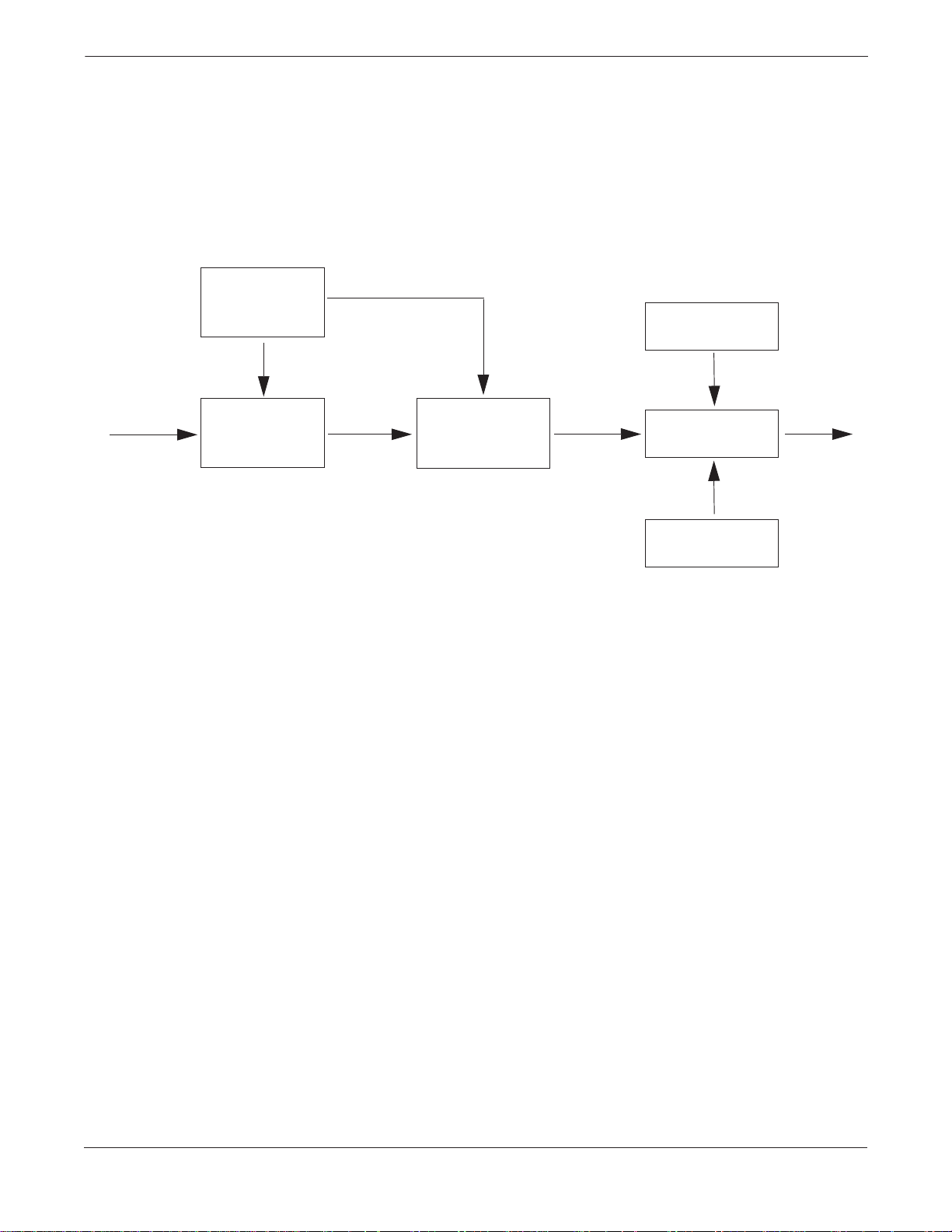
FIGURE 3-1. Model 1151 Transmitter
Data Flow with Calibration Options.
Sensor
Excitation
➀ Pressure
➁
Sensor
Figure 3-1 illustrates the Model 1151 Transmitter data flow with
calibration tasks.
Zero
Adjustment
➂
Signal
Conditioning
➃
Output
Span
Adjustment
Output
This data flow can be summarized in four major steps:
1. Pressure is applied to the sensor.
2. A change in pressure is measured by a change in the sensor
output.
3. The sensor signal is conditioned for various parameters.
4. The conditioned signal is converted to an appropriate analog
output.
3-3
Model 1151 Alphaline® Pressure Transmitters
SPAN ADJUSTMENT
RANGE
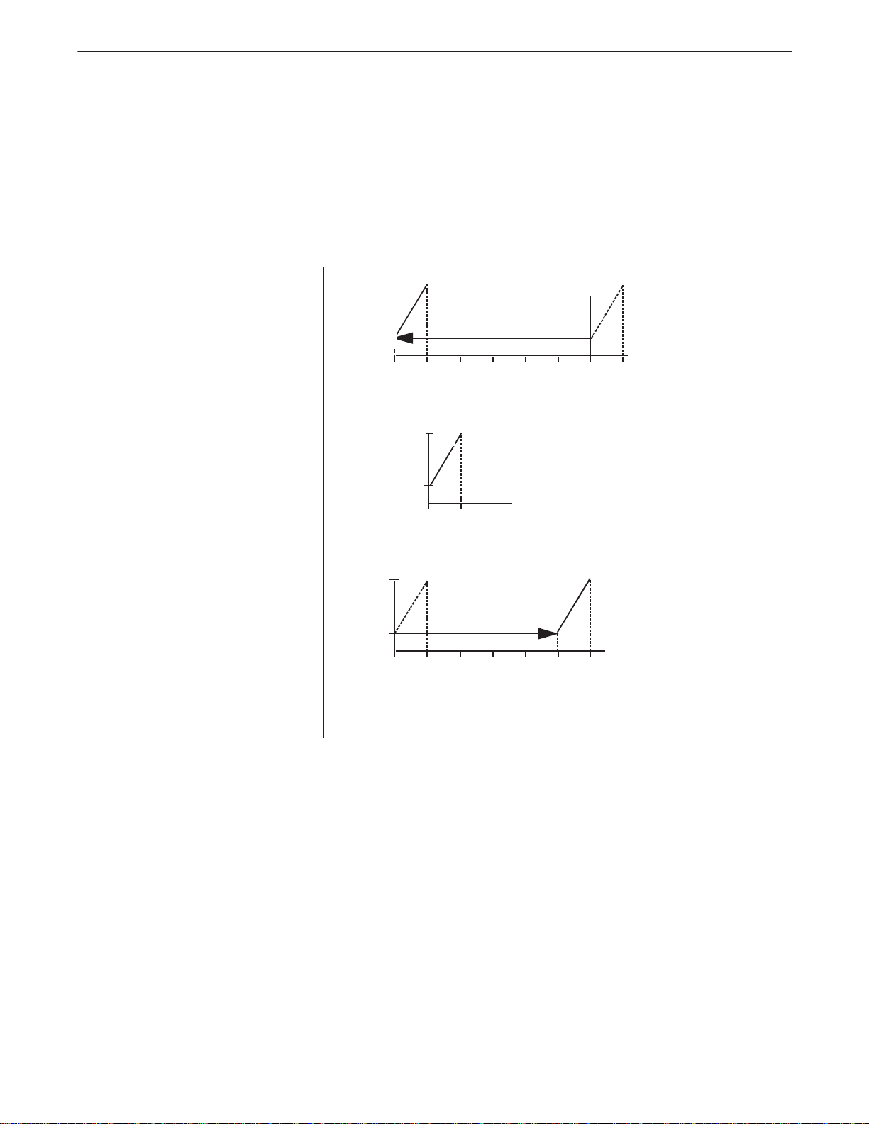
ZERO ADJUSTMENT
RANGE
FIGURE 3-2. Zero Adjustment Range.
The span on a Model 1151 with E, G, and J output options is
continuously adjustable to allow calibration anywhere between
maximum span and one-sixth of maximum span. For example, the span
on a Range 4 transmitter can be adjusted between 25 and 150 inH
O
2
(6.2 and 37.2 kPa).
The zero on a Model 1151 with the E or G output options can be
adjusted for up to 500% suppression or 600% elevation. See Figure 3-2.
Output
(mA)
20
Pressure
O)
(inH
2
–150 –125 –100
Output
(mA)
20
Output
(mA)
600% Zero Elevation
–75
–50 –25 0
600% Zero Elevation*
20
4
0 25
No Zero Elevation or Suppression*
Pressure
O)
(inH
2
4
25
500% Zero Elevation
4
25
0
*Graphs based on a range 4 (0-25 inH2O to 0-150 inH2O) 1151
with a calibrated span of 25 inH
50
500% Zero Suppression*
75
100
O.
2
125
150
1151-0193A
The zero may be elevated or suppressed to these extremes with the
limitation that no pressure within the calibrated range exceeds the fullrange pressure limit. For example, a Range 4 tr ansmitt er cannot be
calibrated for 1 00 to 200 i nH
suppression) because 200 inH
O (24.8 to 49.7 kPa) (only 100% zero
2
O exceeds the 150 inH2O full-range
2
pressure limit of a Range 4.
To make large elevation or suppression adjustments, it is necessary to
move the jumper on the component side of the amplifier board. Figure
3-3 on page 3-5 shows elevation and suppression jumper settings. The
jumper has three positions. The middle position allows normal levels of
elevation or suppression. For larger adjustm ents, move the jumper to
the ELEVATE ZERO (EZ) or SUPPRESS ZERO (SZ) as marked.
3-4
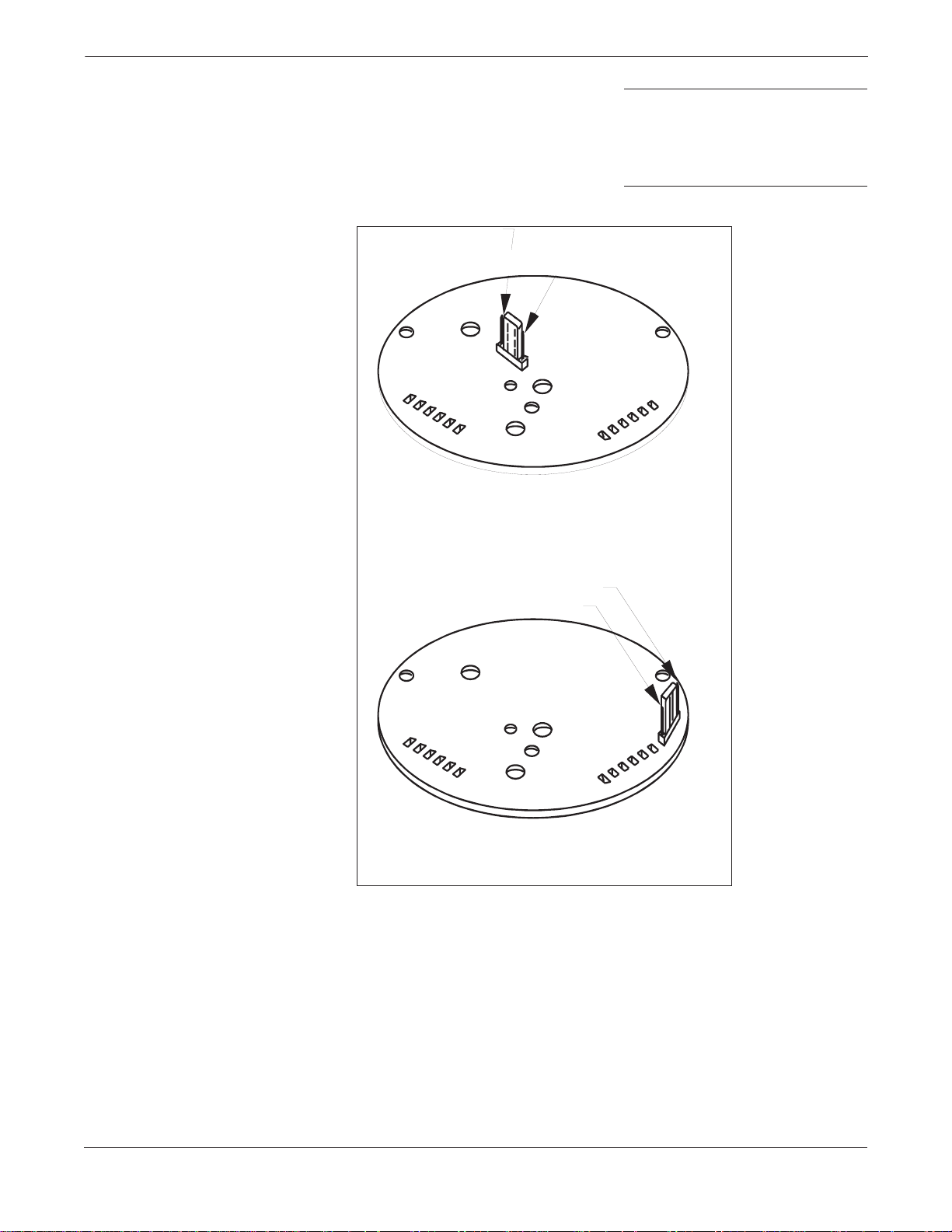
FIGURE 3-3. Elevation and
Suppression Jumper Settings.
Calibration
NOTE
Always make sure that the jumper is fully seated on its pins. If the
jumper has not been placed in any of the three positions, the amplifier
board will provide normal levels of elevation or suppression. A slide
switch replaces the jumper pin on some versions of the amplifier board.
E Output Option
(4–20 mA)
Elevate Zero
Suppress Zero
G Output Option
(10–50 mA)
Suppress Zero
Elevate Zero
NOTE: The jumper is located on the co mpon en t sid e of the
amplifier board. Jumper positions may vary from those shown. The
board must be unplugged from the transmitter to gain acce ss to
the component.
1151-0194A
3-5
 Loading…
- Manuals
- Brands
- Rosemount Manuals
- Measuring Instruments
- 1151
Manuals and User Guides for Rosemount 1151. We have 1 Rosemount 1151 manual available for free PDF download: Product Manual
На этой странице вы можете совершенно бесплатно скачать Инструкция по эксплуатации Emerson Rosemount 1151 Pressure Transmitter.
У документа PDF Инструкция по эксплуатации 22 страниц, а его размер составляет 1.15 Mb.
Читать онлайн Средства личной гигиены Emerson Rosemount 1151 Pressure Transmitter Инструкция по эксплуатации

Скачать файл PDF «Emerson Rosemount 1151 Pressure Transmitter Инструкция по эксплуатации» (1.15 Mb)
Популярность:
1935 просмотры
Подсчет страниц:
22 страницы
Тип файла:
Размер файла:
1.15 Mb