-
Contents
-
Table of Contents
-
Bookmarks
Quick Links
SINUMERIK 828D
Machine Commissioning
This document was produced for training purposes.
Siemens assumes no responsibility for its contents.
Edition 2009.8
Training Manual
Related Manuals for Siemens SINUMERIK 828D
Summary of Contents for Siemens SINUMERIK 828D
-
Page 1
SINUMERIK 828D Machine Commissioning Edition 2009.8 Training Manual This document was produced for training purposes. Siemens assumes no responsibility for its contents. -
Page 3
SINUMERIK 828D Commissioning Manual Turning and Milling Valid for Controller:- Software:- Sinumerik 828D 2.06.28… -
Page 5
Contents B060 System overview. B021 Protection levels. B002 Toolbox Installation. B025 Time and Date Settings B010 PPU Connections and Diagnostics. B044 Licence and Option Commissioning. B017 System Restore. B008 Machine Control Panel . B026 Creating a PLC Program. B019 S7-200 PLC Instructions. B034 PLC Interface. -
Page 7: System Overview
Module Description:- The Sinumerik 828D system is made up of a variety of hardware components. This module gives a graphical overview of those components and shows where each component is connected. A brief description of the hardware components is also given.
-
Page 8: Table Of Contents
Page 6 Panels Section 5 Drive Components Page 10 Section 6 NX10 Module Page 14 Section 7 Sensor Modules Page 15 Section 8 PLC Periphery Page 18 PP72/48 Section 9 Hand-held Units Page 20 B060 B060 Page 2 SINUMERIK 828D…
-
Page 9
PN1 & PN2 Profinet interfaces. X140 X135 RS232 Mini interface X140 X145 Digital I/O X125 X122, X132 & X142 Sinumerik 828D X122 X127 & PPU2xx.1 X132 X142 X143 X100 X101 X102 X130 X130-Facxtory Ethernet Hand-wheels X100, X101 & X103 X127 Service DriveCliq interfaces. -
Page 10
X122 & X132-Digital I/O for Sinamics X142-Digital I/O for NCK X143-Hand-wheels x 2 LED Indicators:- FAULT-Red-fault present, contact Siemens. SYNCH-Green-synchronisation OK Rx/Tx-Yellow network activity LED (1 each for PN1, PN2 & X130 interfaces) Link-Green network connection indicator (1 each for PN1, PN2 & X130 interfaces) -
Page 11
Operational temperature 0-45 °C Operational Relative humidity 5 to 90 % @ 25°C (No condensation) Horizontal model Vertical model Width 310mm(12.2 in) 483mm (19 in) Height 380mm(15in) 220mm (8.66 in) Depth 105mm(4.13 in) 105mm( 4.13 in) B060 SINUMERIK 828D Page 5… -
Page 12
X51 User input connections. X52 User input connections. X55 User input connections. X53 User output connections. X54 User output connections. H1 LED POWER OK H2 LED BUSSYNC H3 LED BUSFAULT S2 IP address selection switch. B060 Page 6 SINUMERIK 828D… -
Page 13: Machine Control
X51 User input connections. X52 User input connections. X55 User input connections. X53 User output connections. X54 User output connections. H1 LED POWER OK H2 LED BUSSYNC H3 LED BUSFAULT S2 IP address selection switch. B060 SINUMERIK 828D Page 7…
-
Page 14
X53 User output connections. X54 User output connections. LED Indicators:- H1 LED POWER OK LED H2 LED BUSSYNC (Bus ok & synchronised) H3 LED BUSFAULT (Bus fault) S1 Hand-wheel type selection switch S2 IP address selection switch B060 Page 8 SINUMERIK 828D… -
Page 15
X53 User output connections. X54 User output connections. LED Indicators:- H1 LED POWER OK LED H2 LED BUSSYNC (Bus ok & synchronised) H3 LED BUSFAULT (Bus fault) S1 Hand-wheel type selection switch S2 IP address selection switch B060 SINUMERIK 828D Page 9… -
Page 16
X24-24V DC electronics supply. U1, V1, W1-3-Phase supply. X200, X201, X202-DriveCliq connections. SLM (16Kw and above) & ALM (All variants) X21-Enable & temperature sensor input. X24-24V DC electronics supply. U1, V1, W1-3-Phase supply. X200, X201, X202-DriveCliq connections B060 Page 10 SINUMERIK 828D… -
Page 17
X21-Enable & temperature sensor input X200, X201, X202-DriveCliq connections. MM –Double X1 & X2-Output to Motors. X21-Enable & temperature sensor input (Motor 1) X22-Enable & temperature sensor input (Motor 2) X200, X201, X202, X203-DriveCliq Single MM Double MM connections. B060 SINUMERIK 828D Page 11… -
Page 18
The braking module is connected to the DC link and 24V DC bus systems. Connector X21 on the braking module is used for enable/fault/ready signals. Connector X1 is for connecting the Braking Module external resistor. B060 Page 12 SINUMERIK 828D… -
Page 19
The initial power to the module is taken from the line supply, when a power failure occurs power is taken from the residual voltage of the DC link. Part number:-6SL3100-1DE22-0AA0 Control Supply Module B060 SINUMERIK 828D Page 13… -
Page 20: Nx10 Module
To maintain consitency with the CU the recommended drive enable connections are:- X122.1 = OFF1 X122.2 = OFF3 A separate 24V DC supply is required in order for the inputs and putputs to function. NX10 Part Number:- 6SL3040-0NC00-0AA0 B060 Page 14 SINUMERIK 828D…
-
Page 21: Sensor Modules
SSI with incremental signals Sin/Cos 1V pp (Temperature evaluation-KTY84-130 can also be used) Interfaces:- X500 DriveCliq. X520 Measuring system input (25 pin D-type connector) X524 24V DC supply Status LED’s Part Number:- 6SL3055-0AA00-5BA1 B060 SINUMERIK 828D Page 15…
-
Page 22
(Screw type connector) Status LED’s X524 24V DC supply Note-The extra measuring system interfaces offer more flexibility for connecting the encoder, The device however can only handle a single encoder. Part Number:- 6SL3055-0AA00-5CA1 B060 Page 16 SINUMERIK 828D… -
Page 23
Absolute EnDat encoders 5V supply-SME125 (Temperature evaluation-KTY84-130 can also be used) Interfaces:- DriveCliq-Also supplies 24V DC. Measuring system input Hall effect sensor input Temperature sensor input Part Number:- 6SL3055-0AA00-5JA0-SME120 6SL3055-0AA00-5KA0-SME25 SME120SME125 B060 SINUMERIK 828D Page 17… -
Page 24: Pp72/48
6FC5311-0AA00-1AA0 Digital/analogue (PP72/48 2/2A PN) A maximum of 4 PP72/48 modules with the PPU260 and PPU261 variants. A maximum of 5 PP72/48 modules with the PPU280 and PPU281 variants. Interface Location:- X111 X222 Port 2 Port 1 X333 B060 Page 18 SINUMERIK 828D…
-
Page 25
PP72/48 No.5 Input range 36 to 44, output range 24 to 29 Switch 1 & 3 on Below:-Example of machine data 12986 set to enable the PP72/48 modules addressed as 8 & 9. The machine data is activated with an NCK power off. B060 SINUMERIK 828D Page 19… -
Page 26
Q1.6 I0.7 Not used Q1.7 I1.0 Not used +24V DC Input I1.1 Not used +24V DC Input I1.2 Q0.0 +24V DC Input I1.3 Q0.1 +24V DC Input I1.4 Q0.2 I1.5 Q0.3 I1.6 Q0.4 I1.7 Q0.5 B060 Page 20 SINUMERIK 828D… -
Page 27
Q5.6 I6.7 Not used Q5.7 I7.0 Not used +24V DC Input I7.1 Not used +24V DC Input I7.2 Q4.0 +24V DC Input I7.3 Q4.1 +24V DC Input I7.4 Q4.2 I7.5 Q4.3 I7.6 Q4.4 I7.7 Q4.5 B060 SINUMERIK 828D Page 21… -
Page 28: Hand-Held Units
6FX2007-1AD13 Mini HHU with straight cable, 5m (16.4 ft) 6FX2006-1BG03 Non assembled connection kit with terminator. 6FX2006-1BG13 Non assembled connection kit without terminator. 6FX2006-1BG20 Pre assembled connection kit with terminator. 6FX2006-1BG25 Pre assembled connection kit without terminator. 6FX2006-1BG70 Holding cradle B060 Page 22 SINUMERIK 828D…
-
Page 29
This module explains the different protection levels, how to set these levels and how to protect individual files. B021 B021 This document was produced for training purposes. SINUMERIK 828D Page 1 Siemens assumes no responsibility for its contents. -
Page 30
Contents: B021 Section 2 Password and Page 3 key-switch information. Section 3 Setting and Deleting Page 4 the Password Section 4 Protection of files Page 6 B021 B021 Page 2 SINUMERIK 828D… -
Page 31
The key switch is located to the bottom right of the MCP and has four positions. Three colour coded keys are available, each of which allow a different access level. This is from a standard Siemens machine control panel. It is possible that a manufacturer may use a different method to set the interface signal. -
Page 32
After typing the password it is confirmed by pressing the “OK” soft key. The dialogue box disappears and the current access level is displayed above the left hand horizontal soft-keys. B021 B021 Page 4 SINUMERIK 828D… -
Page 33
Navigation of the dialogue box is achieved via the cursor and select keys, confirmation is via the “OK” soft key. In this example the “Manufacturer” password is active, this allows the Manufacturer, Service & User passwords to be changed. B021 B021 SINUMERIK 828D Page 5… -
Page 34
Can only be written to (Edited) if the “Manufacturer” password or higher is active Will only be listed if the key switch position 0 or higher is active Can only be read if the key switch position 1 or higher is active B021 B021 Page 6 SINUMERIK 828D… -
Page 35
Section 4 Protection of files Notes When the correct settings have been entered the “OK” soft key has to be selected. B021 B021 SINUMERIK 828D Page 7… -
Page 37
DVD which is supplied with each controller. The software needs to be installed on to a PG/PC before the commissioning procedure commences. B002 B002 This document was produced for training purposes. SINUMERIK 828D Page 1 Siemens assumes no responsibility for its contents. -
Page 38
B002 Contents:- Section 2 Toolbox Installation Page 3 Section 3 RCS Commander Page 13 Installation B002 B002 Page 2 SINUMERIK 828D… -
Page 39
“StartsettingsControl Panel” Please bear in mind that the actual views may differ from PG/PC to PG/PC. Locate and double click the “Add or Remove Programs” icon. Select the “Change or Remove Programs” button. B002 B002 SINUMERIK 828D Page 3… -
Page 40
PG/PC. To reiterate the point made earlier, it is suggested that the software be installed on dedicated hard disk, dual boot system or a VM ware partition. B002 B002 Page 4 SINUMERIK 828D… -
Page 41
Section 2 Toolbox Installation. Notes Software licence agreement:- After reading the agreement! After reading All available programs need to be selected and installed. B002 B002 SINUMERIK 828D Page 5… -
Page 42
The default installation path is “C:Program FilesToolbox 828D. It is good practice to avoid installing to the C drive of the PG/PC. This drive typically contains the operating system installation folders. Use the “Browse” button to select another more suitable drive. B002 B002 Page 6 SINUMERIK 828D… -
Page 43
Use the “Browse” button to select another more suitable drive. Opportunity to choose the installation folder:- Type in the path directly or locate the path via the “Directories” and “Drives” options. B002 B002 SINUMERIK 828D Page 7… -
Page 44
To finalise the setup, Select the “Finish” button to continue. PLC828 Programming Tool. The next item of the Toolbox to be installed is the PLC828 Programming Tool. This follows on when the previous “Finish” button is pressed. B002 B002 Page 8 SINUMERIK 828D… -
Page 45
Enter the user name and company information. As with the configuration files it is recommended that the destination folder is not on the Windows installation drive. This is changed with the “Browse” button. B002 B002 SINUMERIK 828D Page 9… -
Page 46
The program will now be installed. When installation is complete the following dialogue box will be displayed. Acknowledge this with the “Finish” button. Start-up Tool installation. The language can be selected (German or English) B002 B002 Page 10 SINUMERIK 828D… -
Page 47
Section 2 Toolbox Installation. Notes Close all Windows programs before continuing! Licence agreement. The 828D controller operates with the Sinamics drive system, therefore the B002 B002 SINUMERIK 828D Page 11… -
Page 48
When the PC has rebooted, run the “setup.exe” file again. Double click the “Setup.exe” file to start the toolbox installation. The program will display the following dialogue box, select finish to complete the installation. B002 B002 Page 12 SINUMERIK 828D… -
Page 49
“Setup.exe” file to start the toolbox installation. It is possible to choose between two languages, English or German. Allow a few moments for the following dialogue box to appear then select the “Next” key:- B002 B002 SINUMERIK 828D Page 13… -
Page 50
The destination folder can be changed if required. From the drop down menu choose the preferred destination. A new folder can be Created via the “New Folder” button. Confirm the destination folder with the ok button “New Folder” button. B002 B002 Page 14 SINUMERIK 828D… -
Page 51
Section 3 RCS Commander Installation. Continue by selecting the “next” button. Notes Select the “Install” button to start the installation. The installation process begins. A successful installation is confirmed by the following dialogue box. B002 B002 SINUMERIK 828D Page 15… -
Page 53
Before the date and time displays can be edited, the password for the “User” or higher must be entered. B025 B025 This document was produced for training purposes. SINUMERIK 828D Page 1 Siemens assumes no responsibility for its contents. -
Page 54
B025 Contents:- Section2 Setting the Date and Page 3 Time B025 B025 Page 2 SINUMERIK 828D… -
Page 55
The format can be changed by highlighting the required box and using the “Select” If the date or time is changed, each element has to be confirmed using the “Input” key. Once the time & date are correct press the “OK” soft key. B025 B025 Page 3 SINUMERIK 828D… -
Page 57
For the controller to function correctly the interfaces should be correctly connected, the location and functionality of these interfaces is described in this module. B010 B010 This document was produced for training purposes. SINUMERIK 828D Page 1 Siemens assumes no responsibility for its contents. -
Page 58
Contents:- B010 Section 2 PPU Status LED’s and Page 3 Interfaces (Front) Section 3 PPU Status LED’s Page 4 and Interfaces (Rear) Section 4 Digital Input/Output Page 5 Terminal Description B010 B010 Page 2 SINUMERIK 828D… -
Page 59
Booting in System PLC/Periphery fault Progress healthy (Alternating) System healthy Internal NCK error (Flashes at 1Hz) Internal/External CF card access (Flashes randomly) The CF card should not be removed while the CF LED is flashing. B010 B010 SINUMERIK 828D Page 3… -
Page 60
LED Indicators: FAULT fault LED SYNCH synchronisation OK LED Rx/Tx Yellow network activity (1 each for X120, X121, & X130 interfaces) Green network link OK indicator (1 each for X120, X121, & X130 interfaces) B010 B010 Page 4 SINUMERIK 828D… -
Page 61
24V Ground (M) Ground for pins 7 & 8 Pin 10 NCK DI/O 6 DO $A_OUT[2] Pin 11 NCK DI/O 7 DO $A_OUT[1] Pin 12 24V Ground (M) Ground for pins 10 & 11 B010 B010 SINUMERIK 828D Page 5… -
Page 62
0V DC (M) Hand-wheel 2 0V DC common Pin 9 Hand-wheel 2 signal A Pin 10 –2A Hand-wheel 2 signal –A Pin 11 Hand-wheel 2 signal B Pin 12 –2B Hand-wheel 2 signal –B B010 B010 Page 6 SINUMERIK 828D… -
Page 63
This module explains here the licence number can be checked and how to switch on a licensed option. B044 B044 This document was produced for training purposes. SINUMERIK 828D Page 1 Siemens assumes no responsibility for its contents. -
Page 64
Contents:- B044 Section 2 Entering and Checking Licenses Page 3 B044 B044 Page 2 SINUMERIK 828D… -
Page 65
The control should arrive with documentation regarding the licence key and options. This needs to be kept in a secure place. The licence key should be saved at first commissioning and prior to attempting any work where the NC data might be lost/reloaded. B044 B044 SINUMERIK 828D Page 3… -
Page 66
A message is displayed momentarily above horizontal soft-keys To check that the licence save was successful select the “Exp. Licence requirement” soft-key again. The file is automatically given a name by the system. B044 B044 Page 4 SINUMERIK 828D… -
Page 67
To prove that the restoring of the licence works, first delete the existing licence using the “DEL” key . Select the “Read in licence key” soft-key. Highlight the licence key file and press the “OK” soft-key The licence key should now appear in the licence key box. B044 B044 SINUMERIK 828D Page 5… -
Page 68
A “Reset (po)” is required to complete the procedure. If an non-licensed option is activated, the controller will issue an alarm. The NC/Cycle Start will also be inhibited. To see all non-licensed options, select the “Missing licenses” soft-key B044 B044 Page 6 SINUMERIK 828D… -
Page 69
This enables upgrades etc to be carried out while leaving other non-related data in the controller untouched. B003 This document was produced for training purposes. B003 SINUMERIK 828D Page 1 Siemens assumes no responsibility for its contents. -
Page 70
Restoring Archives Page 9 Section 5 Save Data Function Page 12 Section 6 Restore Data Function Page 13 Section 7 Creating a System Page 16 Image Section 8 Restoring a System Page 18 Image B003 B003 Page 2 SINUMERIK 828D… -
Page 71: Data Classes
The right hand column indicates the type of data class that the machine data belongs to. This class will determine whether or not the machine data is included in a particular archive. Data Class Identifier B003 B003 SINUMERIK 828D Page 3…
-
Page 72
The Data Class can be changed via the drop down menu. If the Data Block already exists, the properties can be viewed by right clicking on the Data Block and selecting properties. Selection of the required Data Class. B003 B003 Page 4 SINUMERIK 828D… -
Page 73: Creating Archives
To create a Series Start-up Archive locate the correct area by using the following key Notes sequence. Ensure that the option “Create series start-up” is selected and select “OK” A number of choices are available regarding what to include in the archive you are about to create. B003 B003 SINUMERIK 828D Page 5…
-
Page 74
ASCII is a text file which can be opened with a text editor, this can be useful in upgrade situations where new machine data might prevent the binary file from reading in and/or the data needs to be entered manually. B003 B003 Page 6 SINUMERIK 828D… -
Page 75
USB memory device. Data saved to the “ArchivesManufact” folder is stored on the internal flashcard of the controller. This method ensures that the data remains with the controller. B003 B003 SINUMERIK 828D Page 7… -
Page 76
A suitable name for the archive should be entered. Notes When the archive has been successfully created The dialogue box will clear. A message will be displayed along the bottom of the screen for a few moments. B003 B003 Page 8 SINUMERIK 828D… -
Page 77
The start up menu should be displayed. Use the cursor key to select what action is required. Example:-If an NC archive is to be restored then choose the option “NCK default data”. Press the input key to continue B003 B003 SINUMERIK 828D Page 9… -
Page 78
“Manufacturer” password. If loading several separate archives e.g. NC, PLC. The NC should be loaded before the PLC, the NC may contain data which sets up the memory size for the PLC. B003 B003 Page 10 SINUMERIK 828D… -
Page 79
When the process is complete the functionality of the machine can be tested. It is important that the operator checks tool data, offsets, programs etc as the archive could contain data from some time ago. B003 B003 SINUMERIK 828D Page 11… -
Page 80: Save Data Function
To save data to the internal flash memory locate the correct area by using Notes The “Save data” function is started by selecting the “Save data” soft key:- The data is now stored on the internal flash card. B003 B003 Page 12 SINUMERIK 828D…
-
Page 81: Restore Data Function
Reboot the controller and wait for the following screen to be displayed, immediately this screen appears press the keys indicated in the numerical order shown. Press SELECT key to enter setup menu Cursor to the “Reload saved user data” option and press the “Input” key. B003 B003 SINUMERIK 828D Page 13…
-
Page 82
The operator should be warned of this fact and be prepared to check the data before operating the machine. In the event of the data being automatically reloaded due to the dissipation of the “Goldcap” capacitor., the same message will be displayed. B003 B003 Page 14 SINUMERIK 828D… -
Page 83: Creating A System
To create a system backup enter the Start-up menu:- In a prompt manner press the three highlighted keys in the numerical order indicated. Press SELECT key to enter setup menu Select the option “Create software update/backup” Press the input key to continue B003 B003 SINUMERIK 828D Page 15…
-
Page 84
The file will now be created, as the process continues the file size indicated in the brackets will increase. Message confirming the file was created and requesting removal of storage device and power off/on of the controller. B003 B003 Page 16 SINUMERIK 828D… -
Page 85: Restoring A System Image
Notes In the event of the internal CF card becoming faulty it is necessary to obtain a replacement card from Siemens. A CF card/USB stick containing the system back up image is required along with the replacement CF card of at least 2GB.
-
Page 86
Section 6 Restoring a system image Select the “Write file system image” button on the toolbar of the RCS Commander Notes Browse for the “minsys.img” file. Specify the drive letter of the CF card. B003 B003 Page 18 SINUMERIK 828D… -
Page 87
Notes Remove the CF card and insert it into the rear CF card slot of the controller. Switch the controller on and allow to boot to the following screen then select the “Input” key. B003 B003 SINUMERIK 828D Page 19… -
Page 88
The data backup is now written to the internal card. Allow the process to finish Switch off the controller, remove the front CF card/USB stick and the switch the controller on. Switch off the controller, remove the front CF card/USB stick and the switch the controller on. B003 B003 Page 20 SINUMERIK 828D… -
Page 89
On obtaining a licence key it has to be entered, this process is described in Module B044. The archives used to restore the controller will more than likely contain old data. the data should be checked and the machine tested with this in mind. B003 B003 SINUMERIK 828D Page 21… -
Page 91
In order to function correctly the machine control panel has to be configured using switch settings and machine data, this is described in this module along with various information regarding the interfaces. B008 B008 This document was produced for training purposes. SINUMERIK 828D Page 1 Siemens assumes no responsibility for its contents. -
Page 92
MCP310 Front & Rear Layout Page 6 Section 5 MCP483 Page 8 Input/Output Assignment table Section 6 MCP310 Page 9 Input/Output Assignment table Section 7 MCP Configuration Page 10 Section 8 User I/O Assignment Page 11 B008 B008 Page 2 SINUMERIK 828D… -
Page 93
B008 B008 SINUMERIK 828D Training, Operation and Service Page 3… -
Page 94
B008 B008 SINUMERIK 828D Page 4… -
Page 95
B008 B008 SINUMERIK 828D Page 5… -
Page 96
B008 B008 Page 6 SINUMERIK 828D Training, Operation and Service… -
Page 97
B008 B008 SINUMERIK 828D Training, Operation and Service Page 7… -
Page 98
4th axis 7th axis Single Spindle *Spindl block start e stop QB114 Minus 5th axis Travel 8th axis 6th axis Direction command QB115 MCS/ Plus Unassigned customer keys QB116 Unassigned customer keys QB117 Reset QB118 B008 B008 Page 8 SINUMERIK 828D… -
Page 99
Spindle RESET REPOS Teach In QB113 start right Stop left Feed Feed QB114 Start Stop 1000 QB115 Minus Plus Rapid QB116 Direction Direction traverse QB117 6th axis 5th axis 4th axis MCS/ QB118 QB119 B008 B008 SINUMERIK 828D Page 9… -
Page 100
In this case this is machine data 12986[6]. By default this will have the value of 112. The machine data is activated with an NCK power off. The machine control panel is now ready for use providing the interface signal have been utilised within the user PLC program. B008 B008 Page 10 SINUMERIK 828D… -
Page 101
P24 +24volts Q119.0 Q119.3 Q119.1 Q119.4 Q119.2 Q119.5 M 0volts M 0volts The outputs are capable of supplying 1.2 Watts per output, it is not permissible to connect relays, valves or other inductive devices. B008 B008 SINUMERIK 828D Page 11… -
Page 103
The programming tool PLC828 is used in the creation of a PLC program. This module describes how to use this programming tool. B026 B026 This document was produced for training purposes. SINUMERIK 828D Page 1 Siemens assumes no responsibility for its contents. -
Page 104
B026 Contents:- Section2 Creating a Page 3 PLC program Section 3 Loading a Page 9 PLC program B026 B026 Page 2 SINUMERIK 828D… -
Page 105
To save the project select “Save as” from the drop down menu. The name of the project can be entered then saved. The destination of the file can be changed to suit. B026 B026 Page 3 SINUMERIK 828D… -
Page 106
It makes sense to split the program into subroutines. For example, a subroutine could be written which contains only the code for enabling the axes of a machine. By right clicking on the SBR a suitable name can be entered to assist with fault diagnosis. B026 B026 Page 4 SINUMERIK 828D… -
Page 107
The required operand is selected by the double clicking or drag and drop functions. There are many mathematical functions and logic operations available. By hovering the mouse pointer over a particular operand/instruction a short description will be displayed. B026 B026 Page 5 SINUMERIK 828D… -
Page 108
SBR is inserted. SM0.0 (Special Marker) is always equal to one and is commonly used for this purpose. The Subroutines are stored in the Subroutines folder and are inserted in the network in the same way as operands B026 B026 Page 6 SINUMERIK 828D… -
Page 109
“Ctrl+Y” shortcut, The operand will be displayed in text format. If “Symbolic Information Table” or shortcut “Ctrl+T” is selected, a table will be displayed at the bottom of the network containing the information from the symbol table. B026 B026 Page 7 SINUMERIK 828D… -
Page 110
Providing that there are no errors in the program then the cross reference table will be displayed. Double clicking an element will automatically open the block where that element is used The “Symbolic Addressing” option described earlier also functions with the Cross Reference table. B026 B026 Page 8 SINUMERIK 828D… -
Page 111
“OK” button. Note:-Different PG/PC’s will have different adapter types and not necessarily the ones shown in this example. A dialogue box opens giving the opportunity to cancel the changes Accept by selecting the “OK” button B026 B026 Page 9 SINUMERIK 828D… -
Page 112
Loading the program. Select the “Download” button on the toolbar. Ensure that the option “Blocks (MAIN, SBR, INT, DB)” is selected and select the “OK” button B026 B026 Page 10 SINUMERIK 828D… -
Page 113
The controller will carry out a warm restart, when this complete there should be no errors relating to the PLC and the machine control panel should be operational The functionality of the machine can now be tested with caution. B026 B026 Page 11 SINUMERIK 828D… -
Page 115
Upon completion of this module you will understand the PLC828 Programming Tool instruction list. Module Description: The Sinumerik 828D operates using the in-built S7-200 PLC. Programming is performed with the software package PLC828. This modules describes the instructions available to the user. -
Page 116
Page 21 Or Functions Page 22 Page 24 Move Functions Program Control Page 25 Functions Shift/Rotate Page 28 Functions Timer Page 29 Functions Libraries Page 32 Page 34 Rewire Function Page 36 General Information B019 B019 Page 2 SINUMERIK 828D… -
Page 117
1 0 1 0 0 1 0 1 0 1 1 1 0 0 1 1 Output Words (QD), Marker Words (MD) and Variable Words (VD) can also be used in the same way. B019 B019 SINUMERIK 828D Page 3… -
Page 118: Bit Logic Functions
Markers:- These are internal memory operands which can be used as contacts and coils. They are represented by the letter M e.g. M20.0. They can also appear in Byte, Word and Double Word formats B019 B019 Page 4 SINUMERIK 828D…
-
Page 119
I6.0 = 0 (Low) I6.0 = 1 or (High) Set and Reset example:- I6.5= 0, however Q4.5 remains high I6.6 = 1, this has the effect of because it is a “Set” output resetting Q4.5 to 0 B019 B019 SINUMERIK 828D Page 5… -
Page 120
(Signal state change from 1 to 0) on seeing a falling edge the logic will become true for one scan of the PLC When I6.3 changes from 1 to 0, Q4.4 will become high for one scan of the PLC cycle B019 B019 Page 6 SINUMERIK 828D… -
Page 121
This identifier can be selected from the range of 0-255 Immediate Outputs. These operands are effective immediately upon activation, they are not subject to the PLC scan cycle time. They are identified by the letter “I”. Output Immediate Set Immediate Reset Immediate B019 B019 SINUMERIK 828D Page 7… -
Page 122: Compare Functions
IB6 = 14 and IB7 = 7, IB6 is greater than IB7 so the status is than IB7 so the status is high. low Q5.3 = 0. Q5.3 = 1 This would also be the case if the values were equal. B019 B019 Page 8 SINUMERIK 828D…
-
Page 123: Convert Functions
When I6.0 is true the integer value in MD0 will be converted into a real number and the result placed into MD4. It is also possible to extend the network via the “ENO” output to other operands. The “ENO” output will be high if the convert function was successful. B019 B019 SINUMERIK 828D Page 9…
-
Page 124
Example:- When input I6.3 is true the value in MW18 (96) will be converted into an BCD and the result placed in MW16.(96 = 0000000010010110) Output Q4.6 will become high provided that the value in MW0 is within the ranges specified above and I6.3 remains high. B019 B019 Page 10 SINUMERIK 828D… -
Page 125: Counter Functions
Network 20 is an example of how the counter can be used in the PLC logic. In this case the preset value (PV) of 10 has not been reached so the status is low. Counter C1 with a count value of 6. Preset value (PV) = 10 B019 B019 SINUMERIK 828D Page 11…
-
Page 126
The count value can be reloaded at any time by setting the LD input from low to high. When the counter is first selected in the user program it needs to be given a unique name (Available range C0 to C63). B019 B019 Page 12 SINUMERIK 828D… -
Page 127
10 was entered. The result of this is that the C2 operand is now true as shown in network 22. In this case output Q5.6 is now high. Counter C2 with a count value of 0. Output Q5.6 set high as a result of countdown counter C2 reaching zero. B019 B019 SINUMERIK 828D Page 13… -
Page 128
Preset value (PV) = 10 The C3 operand is high due to the counter value and the preset value being equal. In this example the output Q5.7 is set by the C3 operand. B019 B019 Page 14 SINUMERIK 828D… -
Page 129
The C3 operand is high due to the counter value being more than the preset value. In this example the out- put Q5.7 is set by the C3 operand. B019 B019 SINUMERIK 828D Page 15… -
Page 130
Subtraction of real numbers The SUBTRACT function is parameterised in the same way as the ADD function. When the function runs the IN2 value will be subtracted from the IN1 value and the result placed in OUT. B019 B019 Page 16 SINUMERIK 828D… -
Page 131
Square root of real numbers The Square Root function calculates the square root of a real number. The number to be calculated goes to the IN signal, the result is output to the OUT signal. B019 B019 SINUMERIK 828D Page 17… -
Page 132
(100) — (25) (75) IN1 and has a value of 16.0 MD104 has been assigned to IN2 and has a value of 2.0 Subtracting Double Integers MD208 — MD212 = MD240 (9000) — (3000) = (6000) B019 B019 Page 18 SINUMERIK 828D… -
Page 133
MD212 Decrementing Byte The value in MB200 is decremented by one and the result sent to MB201 Decrementing Word The value in MW200 is decremented by one and the result sent to MW208 B019 B019 SINUMERIK 828D Page 19… -
Page 134: Interrupt Functions
It is better to look in the chart status area. Invert Byte Invert Word Invert Double Word To locate the chart status area select the following icon on the toolbar. B019 B019 Page 20 SINUMERIK 828D…
-
Page 135: And Functions
And Byte And Word And Double Word This is better seen in the Chart Status area. I7.0 and I9.0 are high which sets M238.0 This equivalent operation when written in ladder is seen below:- B019 B019 SINUMERIK 828D Page 21…
-
Page 136: Or Functions
OR Double Word This is better seen in the Chart Status area. If either input or both are high M238.x will be set This equivalent operation when written in ladder format is seen below:- B019 B019 Page 22 SINUMERIK 828D…
-
Page 137
Exclusive OR Double Word This is better seen in the Chart Status area. If either input but not both are high M238.x will be set This equivalent operation when written in ladder format is seen below:- B019 B019 SINUMERIK 828D Page 23… -
Page 138: Move Functions
A positive edge instruction can be used to control the swapping of data more effectively. Swap Function MW68 prior to running the Swap function. MW68 after running the Swap function. B019 B019 Page 24 SINUMERIK 828D…
-
Page 139: Program Control Functions
I7.2 does switch Q8.7 because it was high before the program Jump Instruction was activated. Jump Instruction to Label 1 is active. Q8.7 remains high despite I7.2 being low this because I7.2 was set low after the program Jump Instruction was activated. B019 B019 SINUMERIK 828D Page 25…
-
Page 140
OB1. No further operations after the Conditional End will be processed Example of how the Conditional End Instruction might be used. The Conditional End Instruction is not active. I6.2 is high which switches Q4.1 high B019 B019 Page 26 SINUMERIK 828D… -
Page 141
Shift Right Byte. The Shift Right Byte function operates in the same way as the Shift Left Byte, except that the move is to the right. Below:-Example of a Shift Right Byte by 2 places operation. B019 B019 SINUMERIK 828D Page 27… -
Page 142: Shift/Rotate Functions
The contents of a Double Word can be shifted left or right in the same way that the contents of a Byte or Word can be shifted. The maximum number of moves is 32. Below:-Examples of shifting Double Words. Shift Left: Shift Right: The Results: B019 B019 Page 28 SINUMERIK 828D…
-
Page 143: Timer
Below:- Input I7.0 is high and T1 has started to count. The T1 operand in network 8 is still low as the PT value of 50 has not been reached. T1 value has reached 20 B019 B019 SINUMERIK 828D Page 29…
-
Page 144
Below:- Retentive On-Delay timer T2 has been triggered by I7.1 and the time value has passed the 10 second PT value (100 x 100ms = 10 seconds). The T2 operand is high and has switched Q5.1 high. B019 B019 Page 30 SINUMERIK 828D… -
Page 145
PT (75 x 100ms = 7.5 seconds) the T3 oper- The IN signal has gone low, T3 starts to count up Timer operand T3 remains high B019 B019 SINUMERIK 828D Page 31… -
Page 146: Libraries
Acknowledgement step table for tool change. SP_INI (DB9903) Start data for service planner SP_ACT (DB9904) Actual data for service planner EE_IFC (DB9905) Interface for Easy Extend. The various data blocks are explained in the relevant modules. B019 B019 Page 32 SINUMERIK 828D…
-
Page 147
The INT_101 interrupt block can be used to Interrupt INT_101 Influence the Process Image Table (Outputs) At the end of the scan, the status of the Process Image Table (Outputs) outputs is transferred to the Process Image Table Scan B019 B019 SINUMERIK 828D Page 33… -
Page 148: Rewire Function
The “Rewire” button should then be selected to run the rewire function. Choose the blocks to which the rewire function should be applied Enter the new and old addresses The results of the operation can be seen in the “Rewire Results” area. B019 B019 Page 34 SINUMERIK 828D…
-
Page 149
The changes can also be seen in the subroutines. Rewiring Bytes, Words, Double Words. By selecting the “All accesses within the specified range” option it is possible to rewire Byte, Words and Double Words. B019 B019 SINUMERIK 828D Page 35… -
Page 150: General Information
It must be remembered that in order to make the PLC programme more user friendly for maintenance personnel, the networks should be able to be viewed fully over the width of the screen. B019 B019 Page 36 SINUMERIK 828D…
-
Page 151
B034 1 Brief description. Module Objective: Upon completion of this module you will be know the Sinumerik 828D PLC interface structure and use it to help write the PLC. Module Description: Information to and from the different system areas of the controller is handled by interfaces. This module describes how the different areas operate together. -
Page 152
Contents:- B034 Section 2 Interface Structure Overview Page 3 Section 3 Operand Description & Ranges Page 4 Section 4 Interface Description Page 4 B034 B034 Page 2 SINUMERIK 828D… -
Page 153
PLC Interface Structure Overview. B034 B034 SINUMERIK 828D Page 3… -
Page 154
SM 0.6 PLC cycle (alternating one cycle ’0’, then one cycle ’1’) General Variables that can only be read are identified with [r] Variables that can be read and written to are identified with [r/w] B034 B034 Page 4 SINUMERIK 828D… -
Page 155
Direction 4th axis 7th axis QB 115 Axis selection LED 5th axis Travel 8th axis 6th axis Direction command MCS/ QB 116 Unassigned customer keys QB 117 Unassigned customer keys QB 118 Reset B034 B034 SINUMERIK 828D Page 5… -
Page 156
REPOS Teach In Start right stop left QB113 Feed Feed Inc Var QB114 Start Stop 1000 QB115 Minus Plus Rapid Direction Direction Traverse QB116 QB117 6th axis 5th axis 4th axis QB118 MCS/ QB119 B034 B034 Page 6 SINUMERIK 828D… -
Page 157
Bit 1 Bit 0 1000 Variable Index 1001 Area Number 1002 Line index for NCK variable x (Word) 1004 Column index for NCK variable x (Word) 1006 Data to be written to NCK 1008 B034 B034 SINUMERIK 828D Page 7… -
Page 158
PI-Parameter 8 PI-Parameter 9 4020 4022 PI-Parameter 10 NCK PLC interface [r] DB1200 Byte Bit 7 Bit 6 Bit 5 Bit 4 Bit 3 Bit 2 Bit 1 Bit 0 Fault Finished 5000 5001 5002 B034 B034 Page 8 SINUMERIK 828D… -
Page 159
Bit 7 Bit 6 Bit 5 Bit 4 Bit 3 Bit 2 Bit 1 Bit 0 User area 0000 User area 0001 User area 0002 User area 0004 User area 0126 User area 0127 B034 B034 SINUMERIK 828D Page 9… -
Page 160
6 block 5 block 4 block 3 block 2 block 1 block 0 selected selected selected selected selected selected selected selected 0003 Measuring Skip Skip in jog block 9 block 8 active selected selected B034 B034 Page 10 SINUMERIK 828D… -
Page 161
HMI interface PLC [r] DB1800. Byte Bit 7 Bit 6 Bit 5 Bit 4 Bit 3 Bit 2 Bit 1 Bit 0 0000 Reset AUTO mode mode mode 0001 Machine Machine function:- function:- TEACH 0002 0003 B034 B034 SINUMERIK 828D Page 11… -
Page 162
Deactivate Service Task 2003 Alarm for Service Task [r] DB1800. Byte Bit 7 Bit 6 Bit 5 Bit 4 Bit 3 Bit 2 Bit 1 Bit 0 Alarm 3000 Alarm 3001 Alarm 3002 Alarm 3003 B034 B034 Page 12 SINUMERIK 828D… -
Page 163
Bit 6 Bit 5 Bit 4 Bit 3 Bit 2 Bit 1 Bit 0 0000 MCS/ Simula- Cancel tion selection active [F-K1] 0001 Active HMI area 0002 0003 0004 Active jobshop area 0006 0007 B034 B034 SINUMERIK 828D Page 13… -
Page 164
5002 5003 PLC Hardkeys (Range of values 1….255, 0 is start position 5004 5005 5006 5007 5008 5009 5010 5011 5012 5013 5014 5015 5016 5017 5018 5019 5020 B034 B034 Page 14 SINUMERIK 828D… -
Page 165
Bit 3 Bit 2 Bit 1 Bit 0 1000 Dynamic M functions [F-H2] M1=5 M1=4 M1=3 1001 Dynamic M functions [F-H2] 1002 Dynamic M functions [F-H2] Dynamic M functions [F-H2] 1012 1013 up to 1015 B034 B034 SINUMERIK 828D Page 15… -
Page 166
NCK interface PLC Byte Bit 7 Bit 6 Bit 5 Bit 4 Bit 3 Bit 2 Bit 1 Bit 0 5000 D function 1 (DINT) [F-H2] 5004 Extended address of S function 1 (Byte) B034 B034 Page 16 SINUMERIK 828D… -
Page 167
Bit 1 Bit 0 0000 Emerg. Stop active 0001 INCH Probe 2 Probe 1 dimesion actuated actuated system 0002 Drive Drives in ready cyclic operation 0003 Air temp. alarm alarm is active 0004 0005 0006 B034 B034 SINUMERIK 828D Page 17… -
Page 168
Values from the PLC for the NCK outputs 1010 Output16 Output15 Output14 Output13 Output12 Output11 Output10 Output 9 Set-point screen-form for the NCK outputs 1011 Output16 Output15 Output14 Output13 Output12 Output11 Output10 Output 9 B034 B034 Page 18 SINUMERIK 828D… -
Page 169
Bit 6 Bit 5 Bit 4 Bit 3 Bit 2 Bit 1 Bit 0 Active mode 828D 0000 Ready Auto Active Machine function 0001 Teach in Machine function Continu- 0002 Variable 10000 1000 travel 0003 B034 B034 SINUMERIK 828D Page 19… -
Page 170
(bit/binary coded Circle No tool Activate Neg. Sim. Handwheel Handwheel 0014 change associated direction contour commands for contour hand hand wheel ON wheel Activate Activate skip block skip block 0015 0018 0016 0017 0018 0019 B034 B034 Page 20 SINUMERIK 828D… -
Page 171
Traversing keys Rapid Traversing Feedrate Activate handwheel traverse key lock stop override Geometry axis 3 (Axis 3 in WCS) 1009 Machine function Continu- Inc var INC10000 INC1000 INC100 INC10 INC1 ous travel 1010 1011 B034 B034 SINUMERIK 828D Page 21… -
Page 172
Area 9 Channel specific protection zones violated 0014 Area 8 Area 7 Area 6 Area 5 Area 4 Area 3 Area 2 Area 1 Channel specific protection zones violated 0015 Area 10 Area 9 B034 B034 Page 22 SINUMERIK 828D… -
Page 173
Part pro- search run panel program gram start reset from reset 4005 Circle jog Stop StopbyColl active condition Danger 4006 Silent Asup Any Asup Any Asup Active 4007 4008 Active Transformation Number 4008-4011 Reserved B034 B034 SINUMERIK 828D Page 23… -
Page 174
NCK interface PLC DB370x. Byte Bit 7 Bit 6 Bit 5 Bit 4 Bit 3 Bit 2 Bit 1 Bit 0 0000 M function for spindle (Double Integer) 0004 S function for spindle (Real) B034 B034 Page 24 SINUMERIK 828D… -
Page 175
(resynchro nise 2) Invert M3/ Resyn- Feedrate chronise override 2001 spindle valid for during spindle positioning Setpoint direction of Oscillation Oscillation rotation speed via PLC 2002 Left Right Spindle override 2003 B034 B034 SINUMERIK 828D Page 25… -
Page 176
Bit 7 Bit 6 Bit 5 Bit 4 Bit 3 Bit 2 Bit 1 Bit 0 Positioning Automatic Specified Specified Spindle the spindle gear stage direction of direction of STOP 5006 change rotation rotation B034 B034 Page 26 SINUMERIK 828D… -
Page 177
2001 rotation is Set-point violated increased limited exceeded clockwise range Active spindle mode Rigid SUG active Constant tapping cutting 2002 Control Oscillation Positioning Synchron. velocity active mode mode mode Mode 2003 Spindle in position B034 B034 SINUMERIK 828D Page 27… -
Page 178
5000 5001 Accelera- Velocity Overlaid reaction tion warning movement 5002 initiated warning threshold threshold reached reached Max. Max. Synchroni- Axis accelera- velocity sation acceler- 5003 tion reached running ated reached 5005 5006 5007 5008 B034 B034 Page 28 SINUMERIK 828D… -
Page 179
PLC interface (Read/write) Byte Bit 7 Bit 6 Bit 5 Bit 4 Bit 3 Bit 2 Bit 1 Bit 0 0000 Offset 0 0001 Offset 1 0002 Offset 2 Up to Offset 1023 1023 B034 B034 SINUMERIK 828D Page 29… -
Page 180
DB5700- NCK interface PLC [r] 5704 Byte Bit 7 Bit 6 Bit 5 Bit 4 Bit 3 Bit 2 Bit 1 Bit 0 0000 Axis actual value (Real) 0004 Axis distance to go (Real) B034 B034 Page 30 SINUMERIK 828D… -
Page 181
This module describes how the alarms and messages are activated. The effect an alarm has on the system is shown as well as the method of resetting an alarm. B031 B031 This document was produced for training purposes. SINUMERIK 828D Page 1 Siemens assumes no responsibility for its contents. -
Page 182
B031 Contents:- Section 2 Alarm Configuration. Page 3 Section 3 Entering the Alarm Page 5 Text Section 4 Locating the Alarms Page 8 and Messages Screen. Section 5 Alarm log. Page 9 B031 B031 Page 2 SINUMERIK 828D… -
Page 183
The MD is set via a bit pattern which is revealed when the MD is highlighted and the “Select” key is pressed. The bit is then activated with the “Select” or “Space” key and confirmed with the “OK” soft-key B031 B031 SINUMERIK 828D Page 3… -
Page 184
%d Decimal value %x Hexadecimal %b Binary %o Octal %u Unsigned integer %f Floating point number In the alarm text type:- “Axis %d in parked position”. Press “Input” B031 B031 Page 4 SINUMERIK 828D… -
Page 185
This alarm file determines the text that is displayed when a particular alarm is activated. Creating the text on the controller Use the cursor key to highlight the required alarm type and select “OK” B031 B031 SINUMERIK 828D Page 5… -
Page 186
The colour of the alarm text can be either black or red. This is selected at the right of the text input field. When an alarm text entry is complete press the “Input” key to confirm the entry. The vertical soft-keys offer copy, paste, delete and search functionality. B031 B031 Page 6 SINUMERIK 828D… -
Page 187
Takes the user the beginning of the list. Takes the user the end of the list. Can be used to find a specific word and replace it with another. Cancels the operation. Confirms data entry/starts the search function. B031 B031 SINUMERIK 828D Page 7… -
Page 188
Each alarm number has a variable assigned to it, this variable needs to be set to 1 for the alarm to be displayed. Below is an example of how alarm 700000 might be activated B031 B031 Page 8 SINUMERIK 828D… -
Page 189
The “Settings” soft key is used to refresh the list and display any alarms that have recently occurred. There are a number of options which can be selected by using the cursor and select keys and confirmed with the “OK” soft key:- B031 B031 SINUMERIK 828D Page 9… -
Page 190
Time controlled– The log will be saved at the interval entered in the Write interval area (Max 32000 seconds) This option carries similar risk to the “At every event” option and the same warning is displayed The controller needs to be rebooted to make the changes effective. B031 B031 Page 10 SINUMERIK 828D… -
Page 191
The file can be viewed by using the “Open” soft key. The file can be copied and pasted to other destinations such as an external storage device. This could then, for example be forwarded to technical personnel for fault assistance. B031 B031 SINUMERIK 828D Page 11… -
Page 193
When connected, the remote user will see the exact screen that is displayed on the controller and will be able to enter data to directly influence the system. B032 B032 This document was produced for training purposes. SINUMERIK 828D Page 1 Siemens assumes no responsibility for its contents. -
Page 194
Contents:- B032 Section 2 Remote Diagnosis Page 3 Option Activation Section 3 Configuring the controller Page 4 Section 4 RCS Commander Software Page 6 B032 B032 Page 2 SINUMERIK 828D… -
Page 195
If no tick is available in the “Licensed” column then the current licence is not sufficient and advice must be sought from your local Siemens service centre. If the option required setting it is not active until the controller has had a warm restart via the “Reset (po)”… -
Page 196
If set to “Denied” the connection will be blocked if the dialogue box is not acknowledged. When the settings are correct select the “OK” soft key B032 B032 Page 4 SINUMERIK 828D… -
Page 197
The lower half of the RCS program will show various folders (CF-Card sys- tem, NCK-File system) which are folders on the controller Another indicator of a connection is found on the middle of the RCS program. B032 B032 SINUMERIK 828D Page 5… -
Page 198
Shift & F1 to F8 — Vertical soft-keys F9 — Page Back/Up F10 — Menu Select Shift & F9 — Page right F12 — Help function Escape — Alarm Cancel Select — Space Bar B032 B032 Page 6 SINUMERIK 828D… -
Page 199
ASUP, resetting the active password, saving data, exchanging data between the NC & PLC. This modules explains these functions including the necessary interface signals and shows examples. B033 B033 This document was produced for training purposes. SINUMERIK 828D Page 1 Siemens assumes no responsibility for its contents. -
Page 200
Section 2 (Program Invocation Page 3 Services) Section 3 Reading Axis Positions Page 7 Reading and Writing of Section 4 NC Data Page 8 Section 5 Data Exchange Page 15 Between NC & PLC B033 B033 Page 2 SINUMERIK 828D… -
Page 201
PI-Parameter 8 PI-Parameter 9 4020 4022 PI-Parameter 10 DB1200 NCK PLC interface [r] Byte Bit 7 Bit 6 Bit 5 Bit 4 Bit 3 Bit 2 Bit 1 Bit 0 Fault Finished 5000 5001 5002 B033 B033 SINUMERIK 828D Page 3… -
Page 202
―Target magazine‖ for the tool set in the ―Source location‖. The PLC then receives an order for tool reloading. The ―Target magazine‖ must be a real Magazine. PI Index value Function (DB1200.DBB4001) Initiate order for tool reloading B033 B033 Page 4 SINUMERIK 828D… -
Page 203
To create on the controller use the following soft-key sequence The file will open automatically to allow the program commands to be entered. In this example a 3 second dwell is used. B033 B033 SINUMERIK 828D Page 5… -
Page 204
The ASUP will appear on the ―Automatic‖ machine page and will automatically be executed. When the ASUP has finished running it will be cleared from the screen, any program that was present prior to the ASUP running will now re-appear. B033 B033 Page 6 SINUMERIK 828D… -
Page 205
Below is an example of how the axis position and distance to go values can be read into a marker double word. (MD100) Address for Address for Axis actual position. distance to go DB5700.DBX0000 DB5700.DBX0000 DB5701.DBX0000 DB5701.DBX0000 DB5702.DBX0000 DB5702.DBX0000 DB5703.DBX0000 DB5703.DBX0000 DB5704.DBX0000 DB5704.DBX0000 B033 B033 SINUMERIK 828D Page 7… -
Page 206
0: No error; 1:Illegal access to object; 5: Invalid address; 10: Object does not exist. 3002 3004 Reading data from NCK variable There are seven types of NC variable that can be read/written. These are described in the following tables. B033 B033 Page 8 SINUMERIK 828D… -
Page 207
10: MEASFRAME = Result frame for work piece and tool gauging. 11: WPFRAME = Current 5th system frame (Work piece reference points) 12: WPFRAME = Current 6th system frame (Cycles) The numMachAxes is obtained with the type 4 function. B033 B033 SINUMERIK 828D Page 9… -
Page 208
=0: ―Match all‖ (Buffer) 9999: Undefined (No virtual location) Location type ($TC_MPP2) (Read) DB120x .DBB1000 DB120x .DBB1001 — DB120x .DBW1002 Location number DB120x .DBW1004 Magazine number DB120x .DBD1008 DB120x .DBW3004 Read: Data from NCK variable x (Word) B033 B033 Page 10 SINUMERIK 828D… -
Page 209
128. Assigned to the lower half location Type 9:- Tool number. Location type ($TC_MPP6) (Read) DB120x .DBB1000 DB120x .DBB1001 — DB120x .DBW1002 Location number DB120x .DBW1004 Magazine number DB120x .DBD1008 DB120x .DBW3004 Read: Data from NCK variable x (Word) B033 B033 SINUMERIK 828D Page 11… -
Page 210
1 = Variable is valid signal. For the example it is better to have a value other than zero in the selected R parameter. To locate the R Parameter screen use the following key selection: B033 B033 Page 12 SINUMERIK 828D… -
Page 211
Request complete signal = 1 Error signal = 0 Variable valid signal = 1 The value from R10 will now appear in DB1200.DBD3004. This value remains there only as long as the start signal is present. B033 B033 SINUMERIK 828D Page 13… -
Page 212
It must be ensured that the ―Read/write‖ signal is set to 1 Read/write signal = 1 Start signal = 1 The value from DB1200.DBD1008 will now appear in R10. This value remains there when the start signal is removed. B033 B033 Page 14 SINUMERIK 828D… -
Page 213
This can be checked in the Chart Status of the PLC828 programming tool: To read data the other way is a similar operation. In the MDA area type the line: R11=$A_DBR[4] This will copy the contents of $A_DBR[4] into R11 B033 B033 SINUMERIK 828D Page 15… -
Page 214
The data structure in the data area is defined by the user. Data reading by the NC can activate a pre-read stop (Internal STOPRE) A maximum of 3 sets of data can be written by the NC in the same program block B033 B033 Page 16 SINUMERIK 828D… -
Page 215
PLC. This module shows how to locate and the diagnostic screens and how to use the ladder editor. B058 B058 This document was produced for training purposes. SINUMERIK 828D Page 1 Siemens assumes no responsibility for its contents. -
Page 216
B058 Contents:- Section 2 PLC Diagnostics Page 3 Section 3 Interrupt Routines Page 23 B058 B058 Page 2 SINUMERIK 828D… -
Page 217
Later in the module there is detailed example of how to diagnose a problem with the user PLC programme. NC/PLC Status The status of the operands/variables used within the PLC program can be checked via the “PLC Status” soft key. B058 B058 SINUMERIK 828D Page 3… -
Page 218
DB3804.DBX0.0 is the same as writing V38040000.0 DB3801.DBX1000.7 is the same as writing V38001000.7 DB3801.DBB1000 is the same as writing VB38011000 DB3804.DBW0 is the same as writing VW38040000 DB3804.DBD0 is the same as writing VD38040000 B058 B058 Page 4 SINUMERIK 828D… -
Page 219
For test purposes it may be necessary to manually change (Force) an operand. This is achieved with the “Change” soft key The operand in question has to be highlighted and the new value entered and confirmed with the “OK” soft key Changing M8.0 from 0 to 1 B058 B058 SINUMERIK 828D Page 5… -
Page 220
By selecting the “Display comments” soft-key it is possible to add comments to identify the function of each operand. Confirm the entries with the “Input” key. Insert Variable. The “Insert Variable” soft-key opens a list system variables which can be directly selected for monitoring. B058 B058 Page 6 SINUMERIK 828D… -
Page 221
When the desired variable is found and highlighted, select the “OK” soft-key. The variable will then appear in the NC/PLC Status List. B058 B058 SINUMERIK 828D Page 7… -
Page 222
Further information about the variable can be displayed by selecting the “Display Comments” and “Details” soft-key. Further functions are available when the following soft-key is pressed: Save Screen: The list of operands that have been typed can be saved to a file. B058 B058 Page 8 SINUMERIK 828D… -
Page 223
PLC Diagnostics Notes Type a suitable name for the file. Confirmation of the file save is displayed above the horizontal soft-keys for several seconds. Load Mask: Previously saved files can be loaded using this function. B058 B058 SINUMERIK 828D Page 9… -
Page 224
The value entered in box will become the first number at the top of the list. Each of the three columns can be changed this way . Navigation between the columns is done with the cursor keys. B058 B058 Page 10 SINUMERIK 828D… -
Page 225
“Program stat. ON” soft key. The operands which are true are highlighted in blue. It is recommended that the status be switched when not in use to free more resources for the system. The program status mode is indicated at the top of the screen:- B058 B058 SINUMERIK 828D Page 11… -
Page 226
By selecting the “Symbolic” option, the operands will be displayed with letter notation taken from the symbols table. The “Absolute” selection will display numerical notation. Example:-Network 2 of SBR2 shown in absolute format. B058 B058 Page 12 SINUMERIK 828D… -
Page 227
Further information can be displayed if the “Input” key is pressed Default display Display after “Select” key is pressed. Display after “Input” key is pressed. The display can be magnified via the “Zoom +” and “Zoom -” soft keys. Example:-The display at minimum magnification. B058 B058 SINUMERIK 828D Page 13… -
Page 228
“Search upwards” It is also possible to search in the current program block or all program blocks. When the search parameters are correct the “OK” key is selected to start the search. B058 B058 Page 14 SINUMERIK 828D… -
Page 229
The “Go to” option is used for searching for a network within the open program block The “Find subroutine command” option is used for searching for a specific instruction within the program. Refer to the previous pages for examples of search options. B058 B058 SINUMERIK 828D Page 15… -
Page 230
“Select” key display. The information boxes are cleared with the “Back” Soft key. Symbol table. The “Symbol table” soft key allows different symbol tables to be selected, the tables can also be edited here. B058 B058 Page 16 SINUMERIK 828D… -
Page 231
The changes can be saved while the PLC is in RUN or STOP. A warning message is displayed. Loading in RUN can be dangerous and damaging and should be carried out by trained personnel Make the choice between “Loading in STOP” or “Loading in RUN” B058 B058 SINUMERIK 828D Page 17… -
Page 232
When the dialogue box clears the PLC has to be placed in RUN. After approximately 30 seconds the Operating Status of the PLC should change to run The new entry should be visible when the symbol table is viewed. B058 B058 Page 18 SINUMERIK 828D… -
Page 233
The “Delete” soft-key” is used to remove any unwanted symbol tables. The table is deleted immediately the soft-key is pressed, no confirmation dialogue box is shown. To rename the symbol table use the “Change symbol table” soft-key. B058 B058 SINUMERIK 828D Page 19… -
Page 234
Cross Reference. The “Cross ref.” function allows the user to see what operands are in use and in which blocks they are used. Operands can be located with the “Search” function or the cursor keys. B058 B058 Page 20 SINUMERIK 828D… -
Page 235
PLC going into stop In this case it is alarm “400010 Arithmetic error in user program: Type 1 SBR3 network 1” This tells us that we need to examine network 1 of SBR3 (Subroutine number 3) B058 B058 SINUMERIK 828D Page 21… -
Page 236
When SBR3 is opened and network 1 examined it can be seen that the “Dived” operation is attempting to divide 200 by 0, this is not permitted and so the PLC is put into stop mode. The program needs to be corrected and then loaded to the controller. B058 B058 Page 22 SINUMERIK 828D… -
Page 237
The INT_101 interrupt block can be used to Interrupt INT_101 Influence the Process Image Table (Outputs) At the end of the scan, the status of the Process Image Table (Outputs) outputs is transferred to the Process Image Table Scan B058 B058 SINUMERIK 828D Page 23… -
Page 238
The option to add interrupt block INT100 is given. Details can be added to identify the author and indicate the purpose of the block. Use the “OK” soft-key to complete the action. The interrupt should now appear in the list. B058 B058 Page 24 SINUMERIK 828D… -
Page 239
Select the number “101” with the mouse and press the “OK” soft-key. The interrupt should now be shown in the “Program block” list. To open a block first highlight it and then select the “Open” soft-key. B058 B058 SINUMERIK 828D Page 25… -
Page 240
A choice of a Normally Closed or Normally Open operation is available. (Revealed by the “Select” key) For this example a normally open operation is to be used. Confirm this with the “OK” soft-key. B058 B058 Page 26 SINUMERIK 828D… -
Page 241
“Insert Operation” soft-key The available operations are limited to:- Positive Edge Negative Edge Standard Coil Set Coil Reset Coil. This example is using a standard coil. The operation should be assigned an operand e.g. I7.0 B058 B058 SINUMERIK 828D Page 27… -
Page 242
Loading in RUN can be dangerous and damaging and should be carried out by trained personnel Make the choice between “Loading in STOP” or “Loading in RUN” This is described in more detail on page 17. B058 B058 Page 28 SINUMERIK 828D… -
Page 243
This module shows the different machine data areas and other criteria such as how to activate the machine data. B041 B041 This document was produced for training purposes. SINUMERIK 828D Page 1 Siemens assumes no responsibility for its contents. -
Page 244
B041 Contents. Section 2 Locating The Data Page 3 Areas. Section 3 Data Types. Page 4 Section 4 Data Identifiers Page 5 Section 5 Editing Machine & Page 6 Setting Data B041 B041 Page 2 SINUMERIK 828D… -
Page 245
The above screen is with access level 3 in the General Machine data area. Below shows the same screen with the access level 1 active. Note:- Machine Data is often referred to as “MD” Setting Data is often referred to as “SD” B041 B041 SINUMERIK 828D Page 3… -
Page 246
For further data the “Menu Extension” key must be selected. This allows access to the Setting Data and also the Display Machine Data. General SD influences the whole system. Channel SD influences that particular channel. Axis SD influences the axes. Display MD mainly influences appearance. B041 B041 Page 4 SINUMERIK 828D… -
Page 247
DB380x.DBX4001 bit 0, 1 & 2. This is used, for example, on a spindle with gear stages. The mechanics of each gear range will be different and as such each gear range will require different gain values. B041 B041 SINUMERIK 828D Page 5… -
Page 248
When the correct MD has been found, a value can be entered. In this example we are going to change Display MD 9900 from 0 to 1. This will change the MD/SD description from system language to plain text. B041 B041 Page 6 SINUMERIK 828D… -
Page 249
= Active on selection of the “Reset” key. cf = Active on selection of “Set MD active (cf)” soft key po = Active on control power off/on or “Reset (po)” soft key REMEMBER:- Create a data backup!!!!! B041 B041 SINUMERIK 828D Page 7… -
Page 250
Section 5 Notes A filter option is available so that certain machine data can be masked out. Soft-keys are available for selecting or de-selecting all filter options B041 B041 Page 8 SINUMERIK 828D… -
Page 251
This sequence is described in the module which takes the form of a running example. B068 B068 This document was produced for training purposes. SINUMERIK 828D Page 1 Siemens assumes no responsibility for its contents. -
Page 252
Page 8 Section 5 Configuring the Machine Control Page 10 Panel and Periphery Devices Section 6 Drive Configuration Page 11 (Start-up Tool) Section 7 Axis Enables Page 23 Section 2 Additional Axis Page 24 B068 B068 Page 2 SINUMERIK 828D… -
Page 253
Step 1 Preparation of the controller-Loading standard data. Step 2 PLC part 1-Configuring the MCP and Periphery Devices. Step 3 Drive Configuration-Firmware Update/Topology Recognition Step 4 Assignment of Direct Measuring System Step 5 PLC part 2-Axis Enables B068 B068 SINUMERIK 828D Page 3… -
Page 254
Press SELECT key to enter setup menu The setup menu will be displayed. Cursor to the “Factory settings” option and press the “Input” key. Confirm that this is the procedure to be carried out by selecting the “Yes” option. B068 B068 Page 4 SINUMERIK 828D… -
Page 255
It is possible that the system is not in the desired language, if this is the case the language is easily changed. Setting of the password is now necessary to enable machine data etc to be viewed and altered. B068 B068 SINUMERIK 828D Page 5… -
Page 256
1 in the “Set” column. The control should be allowed to fully boot (green LED) The machine data now has to be changed. Locate the Machine Data area:- B068 B068 Page 6 SINUMERIK 828D… -
Page 257
An NCK reset is required to activate the machines data. It is possible to make all the previous changes and activate with one NCK reset. It makes more sense to follow a certain procedure and not make too many changes at once. B068 B068 SINUMERIK 828D Page 7… -
Page 258
X145 storage and service/commissioning The external PG/PC may need to be adjusted in order to make a connection. In the properties area of the Ethernet connection use the “Obtain an IP address automatically” option B068 B068 Page 8 SINUMERIK 828D… -
Page 259
12986[0] — 192.168.214.64 12986[6] Below:- default setting for MD12986 The hardware is activated by entering a value of –1 in the relevant machine data. The machine datum are activated with a NCK power off. B068 B068 SINUMERIK 828D Page 9… -
Page 260
MCP to the User Interface. Below:-Example of the key-switch interface. Before uploading the programme a connection between the PC/PG and the controller has to be made. The MCP should be tested to ensure it has been correctly interfaced. B068 B068 Page 10 SINUMERIK 828D… -
Page 261
A “SINUMERIK 840D” folder is created on the desktop, this folder contains the NC Connect wizard shortcut. Select the 828D option followed by the “Next” button. Select the “Engineering Tools” option followed by the “Next” button. B068 B068 SINUMERIK 828D Page 11… -
Page 262
The connection setting can be saved with a suitable name, do not change any other settings. Select “Finish” to complete the task. Ensure the correct ethernet cable is connected to the correct sockets. Run the Start- up tool via the “Start-Up Tool” shortcut. B068 B068 Page 12 SINUMERIK 828D… -
Page 263
A dialogue box will be displayed if this is the case. When the dialogue box clears, the whole system, control and drives must be powered off/on. The procedure can then be continued. B068 B068 SINUMERIK 828D Page 13… -
Page 264
Use the “Drive +” / “Drive -” soft-keys to locate the drive which has been incorrectly assigned the DMS. The drive required in this case is servo 6. The “Identify via LED” function can be used to aid the identification of the correct module. B068 B068 Page 14 SINUMERIK 828D… -
Page 265
By paging down to the bottom it can be seen that this drive does in fact have two encoders assigned to it. To re-assign this encoder use the following sequence:- Press the “Next” soft-key until the following screen is displayed. B068 B068 SINUMERIK 828D Page 15… -
Page 266
Continue with the following sequence, a series of dialogue boxes will be temporarily displayed. Press the “Next” soft-key until the following message box appears. As the configuration process is not finished select “No” to the dialogue box. B068 B068 Page 16 SINUMERIK 828D… -
Page 267
In this case it is servo two. Paging to the bottom shows that only one encoder is assigned to this axis at the moment. A similar procedure is carried out to assign the encoder to the correct axis. B068 B068 SINUMERIK 828D Page 17… -
Page 268
“Input” key followed by the sequence of soft-key presses. When the above information box has closed select the “Next” soft-key B068 B068 Page 18 SINUMERIK 828D… -
Page 269
Notes In this case the encoder is a rotary, incremental Sine/Cosine with 1024 pulses per revolution. The encoder position actual value needs to be inverted due to the mounting method on the spindle motor. B068 B068 SINUMERIK 828D Page 19… -
Page 270
The encoder position actual value needs to be inverted due to the mounting method Notes on the spindle motor. Press the “Next” soft-key until the following message box appears. The reassignment of the encoder is completed when the system is restarted. B068 B068 Page 20 SINUMERIK 828D… -
Page 271
As can be seen below the drive objects have no axes assigned to them. Assignment is carried with the following sequence:- Select the drive to be assigned. Use the cursor/select keys to highlight the correct axis for the selected motor and confirm with the “Input” key. B068 B068 SINUMERIK 828D Page 21… -
Page 272
Confirm the selection by pressing the “Accept” key. If more axes are to be assigned select “No, otherwise select “Yes” Select the next drive to be assigned and continue as previously. The assigned axes should be as seen below B068 B068 Page 22 SINUMERIK 828D… -
Page 273
Once the signals for the axes are complete the changes can be downloaded to the controller. The switches should be activated and the motors tested in jog mode. CHANNEL MD 20700 =0 NC start possible without referencing (Not recommended on actual machines) B068 B068 SINUMERIK 828D Page 23… -
Page 274
Drive parameter “P971Save drive object parameters” is set to 1 to save the drive Parameters. When the data has been saved the parameter automatically reverts to a value of 0. B068 B068 Page 24 SINUMERIK 828D… -
Page 275
<control_reset resetnc=“true” /> This activates the new value of the changed machine data. The deactivated axis will no longer appear on the machine page:- Activated:- The functionality of additional axis should be carefully tested. B068 B068 SINUMERIK 828D Page 25… -
Page 277
B053 Drive & Axis Diagnostics 1 Brief description Module Objective:- Upon completion of his module you will be able to use the controller diagnostic functions to help solve drive and axis faults. Module Description: In the event of a problem with the machine it may be necessary to check the status of an axis/drive. The information obtained from these screens can be very useful to technical personnel and help speed up the fault finding process. -
Page 278
B053 Contents. Page 3 Service Overview Screen Section 2 Section 3 Axis Diagnostics Page 5 Screen Page 6 Drive Diagnostics Section 4 Screen B053 B053 Page 2 SINUMERIK 828D… -
Page 279
The signal is missing i.e low (Enable signals only) The signal is indicating a fault (Monitoring signals only) The signal is inactive/not in use. Example:-The diagnostics page showing a motor over temperature problem. B053 B053 SINUMERIK 828D Page 3… -
Page 280
The “All axes” soft-key will display any axes that are currently configured as active or inactive. The “Selected axis” soft-key allows selected axes to be viewed. Example below shows how to view axes 1 & 3 only B053 B053 Page 4 SINUMERIK 828D… -
Page 281
This the quickest method on a machine with many axes. Useful information about the axis in question ranging from positional data to current and torque readings is available. Further information can be seen by using the page/cursor keys. B053 B053 SINUMERIK 828D Page 5… -
Page 282
“Drive system” soft key. The status of the DriveCliq drive objects can be seen. A healthy drive object, fully enabled ready for operation. Status 0 A drive object with a problem i.e. enable missing. Status 31 B053 B053 Page 6 SINUMERIK 828D… -
Page 283
A typical page showing that the MSP1 drive has a status of 31. By using the cursor keys and selecting the “Details” soft key, more information is displayed. For a list of fault numbers and their meaning please consult the following table B053 B053 SINUMERIK 828D Page 7… -
Page 284
Operative — «Infeed operation» = «1» set (p0864) Ready to switch ON — «ON/OFF1» = «0/1» set (p0840) Switching ON interlock — «BB/AUS3» = «1» set (p0848, p0849) Switching ON interlock — remedy fault condition, acknowledge malfunction B053 B053 Page 8 SINUMERIK 828D… -
Page 285
All positioning axes require referencing in order for the controller to position them. The procedures for the referencing of incremental and absolute encoders is described along with the most important machine data. B084 B084 This document was produced for training purposes. SINUMERIK 828D Page 1 Siemens assumes no responsibility for its contents. -
Page 286
B084 Content. Section2 Referencing Incremental Page 3 Encoders Section 3 Referencing Absolute Page 7 Encoders Section 4 Machine Data Page 9 Information Section 5 Automatic Referencing Page 10 B084 B084 Page 2 SINUMERIK 828D… -
Page 287
If it is uncertain whether an axis has an incremental or absolute encoder fitted, this can be checked via axis machine data 30240. To check the machine data use the following soft key sequence. B084 B084 Page 3 SINUMERIK 828D… -
Page 288
Each axis has its own variable which is identified by changing the for a numerical value which represents the axis, see below- 1st axis — DB3800.1000.7 2nd axis — DB3801.1000.7 3rd axis — DB3802.1000.7 etc, etc….. B084 B084 Page 4 SINUMERIK 828D… -
Page 289
The axis should now continue towards the reference switch. Some systems require that the jog direction button is continually depressed throughout the reference cycle, it is more common to find that the axis will continue to move even when the jog direction button is released. B084 B084 Page 5 SINUMERIK 828D… -
Page 290
DBX0.4 1st measuring circuit is referenced 2nd axis — DB3901 DBX0.5 2nd measuring circuit is referenced etc, etc….. The position display will indicate the axis is referenced and display any values stored in machine data 34100 $MA_REFP_SET_POS B084 B084 Page 6 SINUMERIK 828D… -
Page 291
34100 $MA_REFP_SET_POS. Check that machine data 34210 ENC_REFP_STATE is set to 1. This is to enable encoder calibration to take place. Check whether machine data 34010 REFP_CAM_DIR_IS_MINUS is set to B084 B084 Page 7 SINUMERIK 828D… -
Page 292
(150 mm) Machine data 34210 will have changed to 2 to indicate a successful procedure. B084 B084 Page 8 SINUMERIK 828D… -
Page 293
The value entered in here will be displayed on the screen as soon as referencing is complete. This is used when the reference position is not the mechanical zero of the machine. The machine data does not result in the axis physically moving. B084 B084 Page 9 SINUMERIK 828D… -
Page 294
To initiate the automatic cycle the necessary interface bit has to be set. This is variable DB3200.DBX1.0 which is channel related. Example of how the automatic referencing cycle could be initiated. Interface signal DB3300.DBX1.1 changes to 1 whilst the referencing cycle is active. B084 B084 Page 10 SINUMERIK 828D… -
Page 295
Each task has to be parameterised to suit the individual requirements of that task. This module explains how the tasks are created and parameter- ised. B020 B020 This document was produced for training purposes. SINUMERIK 828D Page 1 Siemens assumes no responsibility for its contents. -
Page 296
Setting Up The Page 5 Maintenance Tasks Section 4 XML Data Files Page 7 Section 5 PLC Interface Signals Page 9 Section 6 Confirming/Resetting Page 10 Maintenance Tasks Section 7 PLC Programme Page 12 Example B020 B020 Page 2 SINUMERIK 828D… -
Page 297
It is possible to change the Data Class of the Data Block and add the name of the author if needed. The box is closed by clicking the “OK” key. B020 B020 SINUMERIK 828D Page 3… -
Page 298
Section 2 Enabling The Maintenance Manager Notes Save the user project. Download the Data Blocks to the controller B020 B020 Page 4 SINUMERIK 828D… -
Page 299
To locate the maintenance Planner screen use the following key sequence. Acknowledge the Information box with the ”OK” Soft key. The maintenance tasks are entered by selecting the “Change”, “Cursor”, “Insert” & “OK” keys. Various data has to be entered about the task. B020 B020 SINUMERIK 828D Page 5… -
Page 300
To confirm the data, use the “Input” key, to navigate the dialogue boxes use the cursor keys. When the data required fields have been entered press the “Enter” key. The red clock symbol will be replaced with a green tick B020 B020 Page 6 SINUMERIK 828D… -
Page 301
XML editor for creating an offline file. The file should then be placed in the correct folder. Below is the “oem_maintenance_data.xml” file containing the data of the example used in Section 3. B020 B020 SINUMERIK 828D Page 7… -
Page 302
Task 3: 1st warning Task 3: Quantity Reserved The sequence continues up to the maximum number of tasks (Task 32, data words 248 to 254) Task 32: Interval (Hours) Task 32: 1st warning Task 32: Quantity Reserved B020 B020 Page 8 SINUMERIK 828D… -
Page 303
2002 Deact 24 Deact 23 Deact 22 Deact 21 Deact 20 Deact 19 Deact 18 Deact 17 2003 Deact 32 Deact 31 Deact 30 Deact 29 Deact 28 Deact 27 Deact 26 Deact 25 B020 B020 SINUMERIK 828D Page 9… -
Page 304
Section 6 Confirming/Resetting a Task When a task has reached the time limit, it requires, depending on the task type, some Notes kind of action to be completed. Once this is done then the task can be acknowledged and the time limits reset. Only qualified personnel should reset the task after the maintenance action has been completed. -
Page 305
Section 6 Confirming/Resetting a Task Notes The „Reset all” soft-key will reset the remaining times for all the tasks SINUMERIK 828D Page 11… -
Page 306
Section 7 PLC Programme Example Below is an example of how to activate and reset messages using the Maintenance Notes Planner. Setting the alarm Setting the message Resetting the alarm Resetting the message Deactivating the service interval B020 B020 Page 12 SINUMERIK… -
Page 307
Upon completion of this module you will be able to set-up options using the Easy Extend function. Module description: Easy Extend is a function of the Sinumerik 828D which allows the manufacturer to setup machine options. Typically a prototype machine would be commissioned with all available options. Each option would then be assigned to an Easy Extend device. -
Page 308
Section 6 Page 20 Creating and Restoring A Section 7 “Rollback” archive. Page 22 Addressing of Variables. Section 8 Page 25 General Tag Descriptions. Section 9 Page 32 Tag Descriptions for Section 10 Dialogue Screens. B009 B009 Page 2 SINUMERIK 828D… -
Page 309
As always, before embarking upon tasks of this nature it is always a good idea to save the original status of the machine use the archiving functionality. B009 B009 SINUMERIK 828D Page 3… -
Page 310
Up to 64 devices can be handled by the DB. A set of signals are assigned to each device which are to be used in the user PLC for activating, deactivating and monitoring functions. B009 B009 Page 4 SINUMERIK 828D… -
Page 311
A data block for the password entry should also be created. An example of this is seen below. The user PLC programme will be used to compare the entered and assigned values and providing they match, the device will be enabled. B009 B009 SINUMERIK 828D Page 5… -
Page 312
Resetting the fault bit at initial power on HMI to PLC — Activation Request HMI to PLC — Deactivation Request HMI to PLC-Reset the Password B009 B009 Page 6 SINUMERIK 828D… -
Page 313
The correct directory is found under the following path: System CF cardoemsinumerikhmidvm The correct directory is found under the following path: System CF cardoemsinumerikhmidvm. The AGM.XML is created by selecting the “New” & “Any” soft-keys: B009 B009 SINUMERIK 828D Page 7… -
Page 314
Locate the “dvm” folder as seen below. The top half of shows the files on the host computer. Locate the required file and copy it to the controller using the standard “Copy/paste” function. B009 B009 Page 8 SINUMERIK 828D… -
Page 315
When used in conjunction with the previously written PLC it will be possible to see the device in the Easy Extend area. The option is enabled by the “Enable function” soft-key. Enter the password determined earlier via the PLC program, in this example the password is 1111. B009 B009 SINUMERIK 828D Page 9… -
Page 316
The device is enabled but it is not operational until it is activated. This is achieved by pressing the “Activate” button. A green tick will appear in the “Activated” column to confirm this. B009 B009 Page 10 SINUMERIK 828D… -
Page 317
(DB9905.DBX2.0) In this example the “Deactivate” interface bit (DB9905.DBX0.2) has been also used to reset the password. It is up to the users to decide if this is suitable for their applications. B009 B009 SINUMERIK 828D Page 11… -
Page 318
<!OPTION_MD name = «PLC/DB9000.DBD0″ index=»2» /> <!OPTION_MD name = «PLC/DB9000.DBD0″ index=»3» /> <?include src= «MessageBox_test.xml» ?> <!— ?include src= «option_2.xml» ? —> <!— ?include src= «option_3.xml» ? —> <!— ?include src= «option_4.xml» ? —> </AGM> B009 B009 Page 12 SINUMERIK 828D… -
Page 319
“BTN_OKCANCEL” — OK & CANCEL buttons When the “Activate” soft-key is pressed a message box will appear containing the specified text. To activate the device select the “OK” soft-key. The device will then be activated in the usual way. B009 B009 SINUMERIK 828D Page 13… -
Page 320
<MSGBOX text=»Deactivate Option 1. %n Press OK%n%nAbort press Cancel» caption=»Deactivation of Option» retvalue=»var_return» type=»BTN_OKCANCEL»/> <IF> <condition> var_return==1 </condition> <THEN> <DATA name = «PLC/Q4.7»> 0</DATA> </THEN> <ELSE> <OP> «$actionresult» = 0 </OP> </ELSE> </IF> </SET_INACTIVE> </DEVICE> B009 B009 Page 14 SINUMERIK 828D… -
Page 321
<MSGBOX text=»Deactivate Option 1. %n Press OK%n%nAbort press Cancel» caption=»Deactivation of Option» retvalue=»var_return» type=»BTN_OKCANCEL»/> <IF> <condition> var_return==1 </condition> <THEN> <DATA name = «PLC/Q4.7»> 0</DATA> </THEN> <ELSE> <OP> «$actionresult» = 0 </OP> </ELSE> </IF> </SET_INACTIVE> </DEVICE> B009 B009 SINUMERIK 828D Page 15… -
Page 322
The “Addition. parameter” soft-key is reserved for the instructions contained in the Form tag. Within the Form tag the following tags can be utilised:- INIT PAINT TIMER CLOSE CAPTION SOFTKEY_OK SOFTKEY_CANCEL B009 B009 Page 16 SINUMERIK 828D… -
Page 323
When the device is enabled the “Addition. parameter” soft- key the “tiger.bmp” picture will appear on the screen in the position specified by the IMG tag. The caption “Easy Extend Picture Test” will be displayed in the title bar. B009 B009 SINUMERIK 828D Page 17… -
Page 324
The values are written to the variables when the “OK” soft-key is pressed or can be set to be immediately written. For information on this see the “Hotlink” element under the “Control” tag description. B009 B009 Page 18 SINUMERIK 828D… -
Page 325
The “Last configuration” soft-key is available to restore all the entries to their original values. These values can be checked in the “User variable” area. It is possible to write to other system variables, addressing these variables is described in Section 8. B009 B009 SINUMERIK 828D Page 19… -
Page 326
Archives folder where the AGM files are stored. Storage location of the “Rollback.arc” file:- Restoring a “Rollback” archive. In the event that the previously created archive needs to be restored, the “Restore” soft-key can be selected and the dialogue box acknowledged. B009 B009 Page 20 SINUMERIK 828D… -
Page 327
The file will now be loaded, it is normal for this to take longer than it did to crate the Notes archive. The progress of the read-in is displayed on the dialogue box. On completion the green run LED should be lit and the control be without alarms. B009 B009 SINUMERIK 828D Page 21… -
Page 328
Reading the value of the NC variable (ctrlout_module_nr Axis 1) into the temporary variable (driveindex) <data name =“drive/dc[do$driveIndex]/p0092”>1<data> Using the temporary variable to determine the drive object number and writing a value of 1 into p0092. B009 B009 Page 22 SINUMERIK 828D… -
Page 329
— syg_rm, index 0 and writing a value of 1 to it. <op>“gud/channel/mgud/syg_rm[0]” = 5 2</op> The result of the multiplication of two numbers (5 x 2) is written to the syg_rm[0] gud. B009 B009 SINUMERIK 828D Page 23… -
Page 330
Logical AND operation (Bitwise) Logical AND opertaion &&, && Addition — Subtraction Multiplication Division Not equal to Operations are executed from left to right. Brackets can be used to define the priority of expressions. B009 B009 Page 24 SINUMERIK 828D… -
Page 331
The version number of the drive is copied into the DRIVE VERSION $driveversion variable that is valid within the Device tag A condition used if the instruction was not fulfilled ELSE (Used in conjunction with IF, THEN) B009 B009 SINUMERIK 828D Page 25… -
Page 332
— Extension in the Y direction (Pixels). Example:- <FORM name=“dialog name” color=“#ff000”/> Function call- Executes the functions within the “name” attribute. FUNCTION Attribute: Name — “Name of the function body”. Example:- <FUNCTION name=“function name”/> B009 B009 Page 26 SINUMERIK 828D… -
Page 333
This can be used in the case of alarm numbers, the dialogue box would display the text associated with the alarm number. The NAME instruction defines the name of a device to be NAME displayed in the dialogue screen. B009 B009 SINUMERIK 828D Page 27… -
Page 334
Setting a temporary variable equal to PLC system variable MB100 <op> tmpVar=“plc/mb100” </op> Multiplying a variable by 2. <op> tmpVar= tmpvar * 2 </op> Setting PLC system variable MB100 equal to a temporary variable. <op> “plc/mb100”=tmpVar </op> B009 B009 Page 28 SINUMERIK 828D… -
Page 335
10. <let name=“count=0”</op> <for> <init> <op> count=0 </op> </init> <condition> count <= 7 </condition> <increment> <op count = count +1</op> </increment> <op “plc/qb10” = 1+count</op> </for> B009 B009 SINUMERIK 828D Page 29… -
Page 336
Name — Address of the new interface. Example: <plc_interface name=“address of the new interface”/> With this tag a message will appear instructing the operator to POWER_OFF power down the system. The message text is fixed by the System. B009 B009 Page 30 SINUMERIK 828D… -
Page 337
Providing that this is the case, again write a value of 15 into QB11. When the condition is false, stop the loop. <while> <data name “plc/qb11> 15 </data> <condition> “plc/ib9” ==0</condition> </while> Update Agent Syntax — B009 B009 SINUMERIK 828D Page 31… -
Page 338
If no type is specified, the default is set to “edit”. refvar – label of the reference variable that can be linked to the field. (optional) hotlink – “TRUE“ the field is automatically updated when data is changed (optional) B009 B009 Page 32 SINUMERIK 828D… -
Page 339
An additional possibility is to include the SOFTKEY_OK tag in the form. This tag is then run before the dialog box is closed. In this block — using the UPDATE_CONTROLS instruction — data can be aligned between the control and reference vari- ables. B009 B009 SINUMERIK 828D Page 33… -
Page 340
System CF cardoemsinumerikhmilng <message> <source> MY_TEXT_SYMBOL</source> <translation> Hello World </translation> <chars>20</chars> </message> <text xpos=“10” ypos=“20”>$$MY_TEXT_SYMBOL </text> Example: Indirect text output with text form a variable: <LET name=“TextVar” type=“string”> Hello World </text> <text xpos=“10” ypos=“20“>$$$TextVar </text> B009 B009 Page 34 SINUMERIK 828D… -
Page 341
Using the tag, a variable is included in the cyclic read utility (hotlink). This tag is only valid within the INIT instruction of a form. REQUEST Attribute: Name — address label Syntax: <REQUEST name = “NC Variable“ /> B009 B009 SINUMERIK 828D Page 35… -
Page 342
<let name=»msgbox_result»>0</let> <MsgBox text=»Execute NCK Reset!! » caption = «NCK Re- set» retvalue = «msgbox_result» type= «BTN_OKCANCEL» / > <if> <condition> » msgbox_result » == 1 </condition> <then> <CONTROL_RESET resetnc=»TRUE»/> </then> </if> </softkey_ok> </form> B009 B009 Page 36 SINUMERIK 828D… -
Page 343
The tag should be programmed in the first sub-level of a form tag. The following functions can be executed in this tag: Data manipulation Conditional processing Loop processing SOFTKEY_CANCEL Syntax: Example: <form> <softkey_cancel> <data name=”plc/mb170”>2</data> </softkey_cancel> </form> B009 B009 SINUMERIK 828D Page 37… -
Page 344
Notes B009 B009 Page 38 SINUMERIK 828D… -
Page 345
PLC variables. This module shows how the modem is set up and configured for sending/receiving SMS messages. B018 B018 This document was produced for training purposes. SINUMERIK 828D Page 1 Siemens assumes no responsibility for its contents. -
Page 346
Easy Messenger B018 Section 2 Activating the Modem Page 3 Section 3 Configuring the Modem Page 5 Section 4 Testing the Modem Page 7 Section 5 Setting PLC variables via Page 9 B018 B018 Page 2 SINUMERIK 828D… -
Page 347
LED information:- S (Status) Q (Quality C (Connection) During normal operation:- S — Off Q — On C — Flashes every 2 seconds (Terminal mode active) B018 B018 SINUMERIK 828D Page 3… -
Page 348
The modem setup screens are reached through the following key combination:- Notes When the “Messenger active” soft key is selected the control will start to communicate with the modem. The status of the connection can be seen. B018 B018 Page 4 SINUMERIK 828D… -
Page 349
A limit on the number of SMS messages sent can also be entered and confirmed with the “OK” soft key. When the limit has been exceeded a message box will be displayed. The counter will then have to be reset to zero with the “Reset SMS counter” soft key. B018 B018 SINUMERIK 828D Page 5… -
Page 350
The screen is navigated using the cursor and select keys. More information about some of the events can be seen by pressing the “Details” soft key. B018 B018 Page 6 SINUMERIK 828D… -
Page 351
The user profile can be edited or deleted, further profiles can also be added. A list of text messages that have been sent and received can be seen when the “SMS Protocol” soft key is selected. B018 B018 SINUMERIK 828D Page 7… -
Page 352
MSG(“SMS: TYPE YOUR TEXT IN HERE”) Then press “CYCLE START” The text should then be displayed at the very top of the screen. A message containing the same text should then be received by the designated phone. B018 B018 Page 8 SINUMERIK 828D… -
Page 353
It is also possible to activate and deactivate users in the same way:- 12345 deactivate or 12345 activate. The controller sends out confirmation that the task was successful. A record of these texts can be found in the alarm log page. B018 B018 SINUMERIK 828D Page 9… -
Page 355
The 828D allows the Logbook to be stored on electronically on the controller. The Logbook file can then be saved externally and saved remotely from the controller. B007 B007 This document was produced for training purposes. SINUMERIK 828D Page 1 Siemens assumes no responsibility for its contents. -
Page 356
Contents:- B007 Section 2 Entering The Machine Page 3 Information Section 3 1st Commissioning- Page 5 Start-up Complete 2nd Commissioning- Section 4 Machine Installed Page 6 Section 5 Recording a Service Page 7 Visit B007 B007 Page 2 SINUMERIK 828D… -
Page 357
To change between the different fields of the screen use the cursor keys. To enter the data use the “Input” key. When the full details have been entered press the “OK” soft-key B007 B007 SINUMERIK 828D Page 3… -
Page 358
The Dealer and End User may not be known until after the machine has been built. Notes These areas should be filled in when this information is available. Example:- Dealers information Example:- End User information B007 B007 Page 4 SINUMERIK 828D… -
Page 359
It is important that the time and date is set correctly, please refer to Module B025 for information about setting the time and date. To confirm that 1st Commissioning is complete. To cancel the procedure. The information is now added to the main logbook page. B007 B007 SINUMERIK 828D Page 5… -
Page 360
It is important that the time and date is set correctly, please refer to Module B025 for information about setting the time and date. To confirm that 2nd Commissioning is complete. To cancel the procedure. The information is now added to the main logbook page. B007 B007 Page 6 SINUMERIK 828D… -
Page 361
The name and company/department of the engineer should be entered followed by a detailed description of the fault and work carried out. The details of the service visit are now shown on the Logbook page. B007 B007 SINUMERIK 828D Page 7… -
Page 363
Once the prototype of a particular machine is complete and has been satisfactorily tested, the data from this machine can be transferred quickly into other machines to aid the production process. B067 B067 This document was produced for training purposes. SINUMERIK 828D Training, Operation and Service Page 1 Siemens assumes no responsibility for its contents. -
Page 364
Page 3 Section 3 Creating The Series Start-up Page 4 Archives Section 4 Loading The Controller With Page 6 Default Settings Section 5 Loading The Series Start-up Page 7 Archives B067 B067 Page 2 SINUMERIK 828D Training, Operation and Service… -
Page 365
Data easily transferred from prototype to series machines Compact Flash and USB port locations. The ports are located on the left hand front face of the controller beneath the hinged cover USB port X125 Compact Flash port X145 B067 B067 Page 3 SINUMERIK 828D… -
Page 366
To create a Series Start-up Archive locate the correct area by using the following key sequence. Ensure that the option “Create series start-up” is selected and select “OK” A number of choices are available regarding what to include in the archive you are about to create. B067 B067 Page 4 SINUMERIK 828D… -
Page 367
Select the destination of the archive, as the file is to be transferred between machines this should be the USB or CF. Enter the name of the archive. The archive will now be created and saved in the selected target area. B067 B067 Page 5 SINUMERIK 828D… -
Page 368
The service menu will be displayed, from this menu select the option “Default data” and press “Insert” Allow the control to fully reboot. This action will reset the NCK, PLC, Drives and HMI to factory settings in preparation for the loading of the series start-up archive. B067 B067 Page 6 SINUMERIK 828D… -
Page 369
Acknowledge that the correct file has been selected by pressing “OK”. A dialogue box appears which allows the individual components of the archive to be de-selected. When using the archive to create series machines all the components should be selected. B067 B067 Page 7 SINUMERIK 828D… -
Page 370
“NC” Led will flash orange at approximately 1Hz. Machine specific data can now be entered. Once this is complete further archives should be created as instructed in Module B017. B067 B067 Page 8 SINUMERIK 828D… -
Page 371
1 Brief description Module Objective:- To ensure the necessary level of compatibility and consistency between machines configured with the Sinumerik 828D controller. A defined optimization procedure should be adhered to and this procedure is defined in this module Caution:- These procedures result in axis movement. All necessary safety precautions must be taken into account. -
Page 372
Section 6 Axis Jerk Page 29 Equivalent Time Constant Section 7 Acceleration Page 34 Section 8 Circularity Test Page 36 Section 9 Spindle Optimisation Page 41 Section 10 Advanced Surface Page 57 B100 B100 Page 2 SINUMERIK 828D… -
Page 373
The machine dynamic limits for velocity, acceleration and jerk are set in the inter- polator. The speed control loop is always closed via the motor encoder while the position control loop can be closed via the motor encoder or direct measuring sys- tem. SINUMERIK 828D SL PROFIBUS –DP DRIVE B100 B100… -
Page 374
50% of the frequency response range of measurement is disregarded. Traces can be saved and recalled easily using the ―File Functions‖ softkey. Up to 4 traces can be displayed at one time for comparison if desired. B100 B100 Page 4 SINUMERIK 828D… -
Page 375
Speed setpoint filter time constant P1460 Speed controller Kp P1462 Speed controller Tn P1433 Speed controller reference model frequency P1434 Speed controller ref model damping P1656 Activate current setpoint filters P1657/1676 Current filter settings P1715 Current controller gain B100 B100 SINUMERIK 828D Page 5… -
Page 376
— A reference frequency response of the current controller is a useful check of the current controller parameterisation. — With Siemens motors the parameters are automatically established and should not need to be changed. — With a current controller cycle time of 125us, The db gain should be above –3db to where the phase passes through –90 degrees. -
Page 377
Current Controller Cycle Time Select ―Measurement‖ and then Type of meas- urement ―Refer. Frequ. Response‖ Select ―Measuring parameters‖ and then Select ―Standard pa- rameters‖ The amplitude will vary depending upon motor type and current limit B100 B100 SINUMERIK 828D Page 7… -
Page 378
The db gain should be above –3db to where the phase passes through –90 de- grees. As a minimum the –90 phase point should be above 550Hz Example of P1715 Example of P1715 Too High Too Low B100 B100 Page 8 SINUMERIK 828D… -
Page 379
— Ensure that Dynamic Stiffness is disabled MD32640 = 0 and that (Tn) Drive P1462 is 100ms for horizontal axes and 30ms for vertical or inclined axes, this decreases the influence of the speed controller integrator for this measurement. B100 B100 SINUMERIK 828D Page 9… -
Page 380
Also switch the display to ‖Values in phys. quant‖ to make sure the Off- set and Amplitude are not too large. The amplitude should be varied if the measurement is too noisy. Values in % B100 B100 Page 10 SINUMERIK 828D… -
Page 381
―Pole‖ points are at 769 Hz and 1600 Hz and ―Zero‖ points are at 600 Hz and 1400 Hz. The first 1% and the last 50% of the measurement can be disre- garded. B100 B100 SINUMERIK 828D Page 11… -
Page 382
Kv factor can be reached Select ―Measurement‖ and then ―Speed con- troller path (active. After current setp. Filter) Change the ―Bandwidth‖ from 4000 Hz to 400Hz, and ―Meas periods‖ to 2 B100 B100 Page 12 SINUMERIK 828D… -
Page 383
Panel Take a note of the fre- quencies from 10 Hz to 200 Hz . Here it shows the lowest natu- ral frequency at 66 Hz and also another reso- nance at 120 Hz. B100 B100 SINUMERIK 828D Page 13… -
Page 384
Also if working on a rotary axis only use small values for Amplitude and Offset, quite often if you just use standard values they will be too high. Select ―Drive MD‖ B100 B100 Page 14 SINUMERIK 828D… -
Page 385
Then Select ― ^ ― Select ―Measurement‖ and then Select ―Refer. Frequency response (after speed setpoint filter)‖ Select ―Measuring parameters‖ and then ―Standard pa- rameters‖ but change the offset to 100 mm/min to over- come any friction B100 B100 SINUMERIK 828D Page 15… -
Page 386
200Hz, as this area falls in the bandwidth of the speed controller and therefore we have phase in reserve. Below 200Hz the filters have too much nega- tive influence on the speed control behaviour (they lower the bandwidth, that means less dynamics) B100 B100 Page 16 SINUMERIK 828D… -
Page 387
Reduction should re- main at 0. The filter parameters are automatically loaded into the rele- vant area and the 2nd filter is activated Repeat the ―Reference frequency response‖ measurement to see the effect of the filter. B100 B100 SINUMERIK 828D Page 17… -
Page 388
0db, as the additional load may push the db gain up to the +3db maxi- mum. To optimize Tn se- lect measurement type ―Disturb. Step- change (interf. After current setp.filter) Measured quantity 1 is Actual torque value B100 B100 Page 18 SINUMERIK 828D… -
Page 389
Then just increase Tn until you see no un- dershoot. Most machines of the type fitted with 828D will end up with a value of between 3 to 10ms. B100 B100 SINUMERIK 828D Page 19… -
Page 390
The reference model should have the same value for all axes and the main spindle. P1434, (reference model damping factor) A setting of 0.7 should be used as a start value. Typically values are between 0.5 to 1.0. B100 B100 Page 20 SINUMERIK 828D… -
Page 391
Take a look where the phase passes through –90 degrees and use this frequency as the start value in P1433. For P1434 use a start value of 0.7 In this case P1433 = 220 Hz B100 B100 SINUMERIK 828D Page 21… -
Page 392
P1433[0] and P1434[0] The speed refer- ence model will be active if P1433[0] >0 P1433 should be reduced gradually until the amplitude response is at a maximum of 3db in the lower frequency area B100 B100 Page 22 SINUMERIK 828D… -
Page 393
Sinamics drive with P410 = 3H. Activate DSC (Dynamic Servo Control)..MD 32640 = 1 Adjust Stiffness Delay Time …MD 32644 = 0.0000 PPU281 = -0.0015 PPU261 Select ―Position contr. Loop‖ !!!!! Information !!!!! Position Controller Cycle Time B100 B100 SINUMERIK 828D Page 23… -
Page 394
3ms, 333 Hz for Position controller cycle 1.5ms Select ―Measurement‖ and then Select ―Start‖ You will then get a message saying Press NC Start. Press ―Cycle Start‖ on the Machine Con- trol Panel B100 B100 Page 24 SINUMERIK 828D… -
Page 395
Axis MD 32200 [0] until the ampli- tude response is at the 0db line for as high a frequency as possible, but not rising above 0 db This results in a correctly optimized position controller B100 B100 SINUMERIK 828D Page 25… -
Page 396
-The position actual value trace results should be magnified for a finer view by changing the scale, e.g. position 0.005 mm/div The following NC program can be used FFWOF SOFT LAB: G01 X210 F10000 G04 F0.5 $AA_SCTRACE[X]=1; trigger for servo trace X260 G04 F0.5 GOTOB LAB B100 B100 Page 26 SINUMERIK 828D… -
Page 397
―Display‖ Positioning without Feed Forward. Change the ―Scale of trace 1 & 2 to show a Resolution 0.005mm/div around the target position Without Feed For- ward at all feedrates, no over- shoot is permissi- B100 B100 SINUMERIK 828D Page 27… -
Page 398
KV factor, (MD 32200), being set too high. This might occur when a load weight is added to an axis where the KV factor had been optimized without a load weight. B100 B100 Page 28 SINUMERIK 828D… -
Page 399
5 — 10 mm The following NC program can be used FFWON SOFT LAB: G01 X210 F10000 G04 F0.5 $AA_SCTRACE[X]=1; trigger for servo trace X260 G04 F0.5 GOTOB LAB B100 B100 SINUMERIK 828D Page 29… -
Page 400
Positioning without Feed Forward:-should be comparable with measurement of position controller on the previous pages. The position controller without feed for- ward must have no overshoot and minimal vibration. B100 B100 Page 30 SINUMERIK 828D… -
Page 401
Positioning with Feed Forward active Resolution 0.005mm/div. It can be seen here that the actual value shows no over- shoot as it comes into posi- tion. In this case the EQUIV_SPEEDCTRL_TIME was correct at 0.002 B100 B100 SINUMERIK 828D Page 31… -
Page 402
MD 32200 POSCTRL_GAIN = 0 and can be eliminated MD 32610 VELO_FFW_WEIGHT = 1.0 using jerk limitation. MD 32620 FFW_MODE = 3 MD 32810 EQUIV_SPEEDCTRL_TIME = 0.002 MD 32431 MAX_AX_JERK = 100 B100 B100 Page 32 SINUMERIK 828D… -
Page 403
MD 32810 EQUIV_SPEEDCTRL_TIME = 0.002 MD 32431 MAX_AX_JERK = 120 MD 20150[23] =2 Feed Forward can then be enabled as a default. MD 36012 STOP_LIMIT_FACTOR = original value MD 36400 CONTOUR_TOL = original value B100 B100 SINUMERIK 828D Page 33… -
Page 404
LAB: G0 X10 $AA_SCTRACE[X]=1; trigger for servo trace X310 GOTOB LAB Change the trace measuring parame- ters to view ―Velocity act value meas sys- tem 1‖, ―Utilization (m_set/m_set_limit)‖ and ―Torque-prod curr. Act. val i(q)‖ B100 B100 Page 34 SINUMERIK 828D… -
Page 405
P 0640 is limited to whichever is the lower of P0323 Maximum Motor Current/ Mot I Max [RMS amps] or r0209 Power Unit Maximum Current/ PU I Max [RMS amps] In this example P640 was 35A Therefore utilization is 35A x 36.28/100 = 12.7A B100 B100 SINUMERIK 828D Page 35… -
Page 406
Example of an X-Y circle part program – Position, feedrate and active plane must be adapted to the machine! FFWON SOFT G90 G01 F3000 X400 Y200 Z500 LAB: G91 G64 G02 X0 Y0 I10 GOTOB LAB Select ―Optimiz/test‖ B100 B100 Page 36 SINUMERIK 828D… -
Page 407
— Measurement, select the relevant axis and the ―active‖ measuring system. — Parameter, enter the programmed radius and feedrate. The multiplier should remain at 1. — Resolution, set the resolution as desired, e.g. 0.010 mm/grad — Representation, select ―Mean radius‖. B100 B100 SINUMERIK 828D Page 37… -
Page 408
Feedrate = Entered feedrate (e.g. 3000 mm/min) Measuring time = Calculated time for the measurement Representation: Resolution = units per graduation (e.g. 0.010 mm/div) Represent = Type of display, (e.g. mean) Radius = Actual radius Delta R = p/p deviation B100 B100 Page 38 SINUMERIK 828D… -
Page 409
The circle size is now corrected using AX_JERK_TIME 32200 POSCTRL_GAIN 4.500 4.500 P1460 SPEEDCTRL_GAIN1 P1462 SPEEDCTRL_INTEGRATOR_TIME_1 4.0 P1433 SPEEDCTRL_REF_MODEL_FREQ 220.0 220.0 P1440 NUM_SPEED_FILTERS 32610 VELO_FFW_WEIGHT 32620 FFW_MODE 32810 EQUIV_SPEEDCTRL_TIME 0.002 0.002 32400 AX_JERK_ENABLE 32402 AX_JERK_MODE 32410 AX_JERK_TIME 0.013 0.013 B100 B100 SINUMERIK 828D Page 39… -
Page 410
32410 AX_JERK_TIME 0.012 0.014 32200 POSCTRL_GAIN 4.500 4.500 P1460 SPEEDCTRL_GAIN1 P1462 SPEEDCTRL_INTEGRATOR_TIME_1 4.0 P1433 SPEEDCTRL_REF_MODEL_FREQ 220.0 220.0 P1440 NUM_SPEED_FILTERS 32610 VELO_FFW_WEIGHT 32620 FFW_MODE 32810 EQUIV_SPEEDCTRL_TIME 0.002 0.002 32400 AX_JERK_ENABLE 32402 AX_JERK_MODE 32410 AX_JERK_TIME 0.015 0.011 B100 B100 Page 40 SINUMERIK 828D… -
Page 411
8800 MD 36300 ENC_FREQ_LIMIT[0] 100000 Encoder limit frequency MD 36300 ENC_FREQ_LIMIT[1] 100000 MD 36400 CONTOUR_TOL[ Tolerance band for contour monitoring P 1433 SPEED_CONTROLLER_REFERENC Same as the axis which interpolates with E_MODEL_NATURAL_FREQUENCY The spindle e.g.Z B100 B100 SINUMERIK 828D Page 41… -
Page 412
7.1 Carry out a frequency response measurement on the speed controller Select ―Startup‖ then ―Optimiz./test‖. Select ―Axis +‖ until the Main Spindle is reached. Then Select ―Speed contr. Loop‖ Select ―Measurement‖ and then Type of Measurement ―Refer frequency response (after speed setpoint filter)‖ B100 B100 Page 42 SINUMERIK 828D… -
Page 413
Control Panel When the meas- urement I finished Select ―Display‖ to view the results. Here it can be seen that the Pro- portional Gain of the speed control- ler can be in- creased. B100 B100 SINUMERIK 828D Page 43… -
Page 414
(e.g. above 800Hz) then a value can be used in P 1441[0] ACTUAL_SPEED_SMOOTHING_TIME. Values between 0.3—0.5 are useful Select the 2nd filter and make it a Band Stop filter. Then enter in the rele- vant parameters B100 B100 Page 44 SINUMERIK 828D… -
Page 415
Example: P1460 = 8, P1461 =20%, Kp upper adaption = 8 x 20% = 1.6 Nms/rad P1462 = 10, P1463 = 600%, Tn upper adaption = 10 x 600% = 60 ms P1464 = 850, P1465 = 3400. B100 B100 SINUMERIK 828D Page 45… -
Page 416
Type of measurement ―Ref frequency respo‖ Select ―Measuring pa- rameters‖ and then enter tha values shown. Bandwidth 166 Hz for Position controller cy- cle 3ms, 333 Hz for Position controller cy- cle 1.5ms B100 B100 Page 46 SINUMERIK 828D… -
Page 417
It can be seen here that MD 32200 can be in- creased but the amplitude should not come above Select ―Axis MD‖ and search for 32200. The value can then be increased B100 B100 SINUMERIK 828D Page 47… -
Page 418
9.4 A part program should now be created to check the spindle positioning without overshoot, and the servo trace function should be used to view the results. LAB: SPOS=0 G4 F1 SPOS=130 G4 F0.2 GOTOB LAB Select ―Servo trace‖ from the ―Startup‖, ―Optimiz./test‖ menu B100 B100 Page 48 SINUMERIK 828D… -
Page 419
In some cases it may be necessary to switch drive pa- rameter sets in or- der to optimize per- formance in differ- ent gear ranges B100 B100 SINUMERIK 828D Page 49… -
Page 420
NC. Set MD 35200[1] $MA_GEAR_STEP_SPEEDCTRL_ACCEL to a maximum e.g. 9999 rev/s2 ( t=V/a t=9000/60s/9999 t=15ms therefore no influence) Now look at the motor data sheet E.g. 1PH7101-2QF02-08J3 asynchronous motor B100 B100 Page 50 SINUMERIK 828D… -
Page 421
78 % Select ―Servo trace‖ from the ―Startup‖, ―Optimiz./ test‖ menu Enter the Trace selections as shown. Select ―Measurement‖ and then ―Start‖ Once spindle ac- tual speed is above 5 rpm the trace will start. B100 B100 SINUMERIK 828D Page 51… -
Page 422
-40 Nm P1530 Power limit motoring 6,5 KW P1531 Power limit regenerating -6,5 KW P326 motor stall torque correction factor (original 78 % value) Now repeat the servo trace test with the MDA program B100 B100 Page 52 SINUMERIK 828D… -
Page 423
First change P10 = 3 ( Motor commissioning) Then P300 = 1 ( Induction motor) Now P326 can now be adjusted P10 should be returned to 0 P326 =100 % Acceleration now 1.77 seconds B100 B100 SINUMERIK 828D Page 53… -
Page 424
P1530 Power limit motoring 6,5 KW P1531 Power limit regenerating -6,5 KW 105 % P326 motor stall torque correction factor Adjust MD 35200[1] $MA_GEAR_STEP_SPEEDCTRL_ACCEL to give the machine tool builders requirement for spindle acceleration B100 B100 Page 54 SINUMERIK 828D… -
Page 425
Example of an X-Z circle part program with Spindle coupled to X axis FFWON SOFT TRAILON(SP1,X,1) G90 G01 F3000 X400 Z400 LAB: G91 G64 G02 X0 Z0 I10 GOTOB LAB Select ―Circularity test‖ B100 B100 SINUMERIK 828D Page 55… -
Page 426
―Cycle Start‖ on the machine control panel. Once the program is running select ―Start‖ Once the circularity test is finished select ―Display to see the result. NOTE spindle resolu- tion is in fractions of a degree. B100 B100 Page 56 SINUMERIK 828D… -
Page 427
Also consider Cycle 832 and Cycle 832T. When the Technology G Groups are used there is no longer a reason to over- write machine data via cycles etc !!!!!! Simplify the handling of the parameters as much as possible !!!!! B100 B100 SINUMERIK 828D Page 57… -
Page 428
Bit 0 = 0 Normal state Bit 0 = 1 Advanced surface Bit 1 = 0 COMPOF Bit 1 = 1 COMPCAD When finishing or when AS is required then Bit 0 = 1 and Bit 1 = 1 B100 B100 Page 58 SINUMERIK 828D… -
Page 429
For 3 Axis operation SOFT COMPCAD G642 for SW stands <= 72.05 G645 for SW stands >= 72.06 FIFOCTRL FFWON DYNROUGH, DYNSEMIFIN or DYNFINISH 10.6 Set $MA_MAX_ACCEL_OVL_FACTOR[4] to 1.01 for all axes for operation with DYNFINISH B100 B100 SINUMERIK 828D Page 59… -
Page 430
Manufact 20600[2] $MC_MAX_PATH_JERK 10000 DYNROUGH Manufact 20600[3] $MC_MAX_PATH_JERK 10000 DYNSEMIFIN Manufact 20600[4] $MC_MAX_PATH_JERK 10000 DYNFINISH Manufact 20602[0] $MC_CURV_EFFECT_ON_PATH_ACCEL Manufact 20602[1] $MC_CURV_EFFECT_ON_PATH_ACCEL Manufact 20602[2] $MC_CURV_EFFECT_ON_PATH_ACCEL Manufact 20602[3] $MC_CURV_EFFECT_ON_PATH_ACCEL Manufact 20602[4] $MC_CURV_EFFECT_ON_PATH_ACCEL Manufact 20603[0] $MC_CURV_EFFECT_ON_PATH_JERK Manufact B100 B100 Page 60 SINUMERIK 828D… -
Page 431
$MA_MAX_AX_JERK Standard DYNROUGH Manufact 32431[3] $MA_MAX_AX_JERK 20,00 DYNSEMIFIN Manufact 32431[4] $MA_MAX_AX_JERK 20,00 DYNFINISH Manufact 32432[0] $MA_PATH_TRANS_JERK_LIM Standard DYNNORM Manufact 32432[1] $MA_PATH_TRANS_JERK_LIM Standard DYNPOS Manufact 32432[2] $MA_PATH_TRANS_JERK_LIM Standard DYNROUGH Manufact 32432[3] $MA_PATH_TRANS_JERK_LIM 20,00 DYNSEMIFIN Manufact B100 B100 SINUMERIK 828D Page 61… -
Page 432
Section 10 Advanced Surface 32432[4] $MA_PATH_TRANS_JERK_LIM 20,00 DYNFINISH Manufact Notes 32620 $MA_FFW_MODE Manufact 42471 $SC_MIN_CURV_RADIUS Manufact B100 B100 Page 62 SINUMERIK 828D… -
Page 433
B051 1 Brief description Module Objective: Upon completion of this module you will know how the drive components of the Sinumerik 828D sys- tem are integrated and how the power to these components should be applied and moved. Module Description: The Sinumerik 828D operates with Sinamics drive components, these components must be powered on/off in a certain sequence. -
Page 434
Page 3 Smart Line Module (SLM) Section 3 Section 3 Page 10 Active Line Module (SLM) Section 4 Section 4 Page 13 Motor Module (MM) Section 5 Section 5 Page 17 Supply and Enabling Examples B051 B051 Page 2 SINUMERIK 828D… -
Page 435
LED status Indicators (See page 6) X1: Mains supply Protective earth (3-Phase AC) connections. Terminal descriptions. X1-Mains power connector. Terminals:- U1, V1, W1 Supply:- 380V to 480V 3 phase AC +10% (-15% < 1 min) B051 B051 SINUMERIK 828D Page 3… -
Page 436
0V DC Bus-bar + DC Link Bus-bar — DC Link Bus-bar Location of SLM connectors X21 & X22. X21: X22: Enable, ready and Regeneration and fault signals. fault reset signals. X24: 24V DC Electronics supply B051 B051 Page 4 SINUMERIK 828D… -
Page 437
This is not suitable for an emergency stop situation. Enable Pulses Must be connected to the 0V of the enable pulses (Ground) supply. B051 B051 SINUMERIK 828D Page 5… -
Page 438
READY dropped out. (Top) Over temperature/current fault or electronics power supply outside permitted range. Electronics power supply outside permitted range. DC LINK Yellow DC link voltage within tolerance. (Bottom) DC link voltage outside tolerance. B051 B051 Page 6 SINUMERIK 828D… -
Page 439
LED status Indicators. (See page 9) Protective earth terminals. X1: Mains supply (3-Phase AC) Terminal description. X1-Mains power connector. Terminals:- U1, V1, W1 Supply:- 380V to 480V 3 phase AC +10% (-15% < 1 min) B051 B051 SINUMERIK 828D Page 7… -
Page 440
+ DC Link Bus-bar — DC Link Bus-bar Location of SLM connectors X21, X22, X200, X201 & X202. X21: Pulse enable. X202: DriveCLiQ connector. X201: DriveCLiQ connector. X200: DriveCLiQ connector. X24: 24V DC Electronics supply. B051 B051 Page 8 SINUMERIK 828D… -
Page 441
Orange Electronics power supply outside permitted range. DC LINK Orange DC link voltage within tolerance-Only if unit is con- (Bottom) figured and ready. DC link voltage outside tolerance-Only if unit is configured and ready. B051 B051 SINUMERIK 828D Page 9… -
Page 442
(Below flip down cover). LED status Indicators. (See page 12) Protective earth 3-Phase AC Mains supply Terminal description. Terminals:- U1, V1, W1 Supply:- 380V to 480V 3 phase AC +10% (-15% < 1 min) B051 B051 Page 10 SINUMERIK 828D… -
Page 443
Bottom bus-bar: 0V Location of ALM connectors X21, X22, X200, X201 & X202 X21: Enable and Temperature sensor Connections. X203: DriveCLiQ connector. X202: DriveCLiQ connector. X201: DriveCLiQ connector. X200: DriveCLiQ connector. X24: 24V DC Electronics supply. B051 B051 SINUMERIK 828D Page 11… -
Page 444
Red/ Orange Electronics power supply outside permitted range. Orange DC link voltage within tolerance-Only if unit is DC LINK configured and ready. (Bottom) DC link voltage outside tolerance-Only if unit is configured and ready. B051 B051 Page 12 SINUMERIK 828D… -
Page 445
Screw terminals. Not on Fixing screw housing, also used for Crimped cable types. cable shield. Brake: Positive Brake: Negative Connection Connection Locating key- Locating key- Changeable Changeable Motor: Phase U Motor: Phase V Motor: Phase W B051 B051 SINUMERIK 828D Page 13… -
Page 446
Both bus bar systems originate from the SLM/ALM modules. 24V DC Electronics supply (X24) Bridging device for continuity of the bus between drive modules. +24V DC Bus-bar 0V DC Bus-bar + DC Link Bus-bar — DC Link-Bus-bar B051 B051 Page 14 SINUMERIK 828D… -
Page 447
Unit and Motor Module. The status of the Enable Pulses input is cross checked against the corresponding CU input, an error is reported if they do not match. Enable Must be connected to the 0V of the enable pulses Pulses supply. (Ground) B051 B051 SINUMERIK 828D Page 15… -
Page 448
Red/ Orange Electronics power supply outside permitted range. DC LINK Orange DC link voltage within tolerance-Only if unit is (Bottom) configured and ready. DC link voltage outside tolerance-Only if unit is configured and ready. B051 B051 Page 16 SINUMERIK 828D… -
Page 449
X21.2 I2t warning (Output from SLM) X21.3 Enable pulses 24V (Input to SLM) X21.4 Enable pulses 0V (Input to SLM) 828D X122.1 Line Module Ready OFF1 signal (Input to 828D) X122.2 Drive Enable OFF3 (Input from E stop circuit) B051 B051 SINUMERIK 828D Page 17… -
Page 450
B051 B051 Page 18 SINUMERIK 828D… -
Page 451
B051 B051 SINUMERIK 828D Page 19… -
Page 452
B051 B051 Page 20 SINUMERIK 828D… -
Page 453
B051 B051 SINUMERIK 828D Page 21… -
Page 454
B051 B051 Page 22 SINUMERIK 828D… -
Page 455
It is also essential that the cabinets are designed to prevent/minimise the ingress of contaminants. This module explains what is required to produce an acceptable electrical cabinet and what “Sins” to avoid. B006 B006 This document was produced for training purposes. SINUMERIK 828D Page 1 Siemens assumes no responsibility for its contents. -
Page 456
Arrhenius’ Law Page 5 Section 4 Cabinet Cooling Page 6 Section 5 Equipment Mounting Page 10 Section 6 Plugs, Sockets and Cabling Page 12 Section 7 Cabinet Sealing. Page 14 Section 8 Miscellaneous. Page 15 B006 B006 Page 2 SINUMERIK 828D… -
Page 457
Sin 6 Electrical cables must be routed so that sensitive signal cables are kept separate from the power cables. Sin 7 DC link bus-bar connections must be tightened to the recommended torque. B006 B006 SINUMERIK 828D Page 3… -
Page 458
If the temperature is allowed to get too high the lifetime of the components will be reduced. If the temperature is set too low there is a risk of condensation forming on the electronic components which can also be detrimental to the equipment. B006 B006 Page 4 SINUMERIK 828D… -
Page 459
(50% reduction in life time) Expected Defect Life Rate Time 9.00 120% — 8.00 — 100% 7.00 — 6.00 — 5.00 — 4.00 — 3.00 — 2.00 — 1.00 — 0.00 — -10K Temperature Change B006 B006 SINUMERIK 828D Page 5… -
Page 460
Roof mounted cooling units Outlet ≥ 200mm Potential obstruction Electrical cabinet Electrical cabinet The use of baffles is recommended to prevent ventilation short circuits where the exhaust air is taken directly into the cooling units. B006 B006 Page 6 SINUMERIK 828D… -
Page 461
The outside of the cooling unit must be protected from any possible contamination such as coolant, machine waste etc. B006 B006 SINUMERIK 828D Page 7… -
Page 462
Drive equipment equipment Cold air directed straight Warm air intake at the onto drive equipment bottom of the cooling will cause condensation unit. problems. Incorrectly installed cooling unit Wrong type of cooling unit used. B006 B006 Page 8 SINUMERIK 828D… -
Page 463
The fan takes air in at the bottom and the the rear of a cabinet with a cut-out cover creates a chimney effect to give a good ready to accept another module. cooling effect. B006 B006 SINUMERIK 828D Page 9… -
Page 464
The mounting plate for the equipment should be one of bare metal, this acts as a central earth point and also improves the EMC. Left:-A bare metal backplane ready for the drive modules to be mounted, note the earth bonding cables, one for each drive module. B006 B006 Page 10 SINUMERIK 828D… -
Page 465
≥ 100mm Shielded Power Cables. Shielded Motor Cables. Shield plates for grounding the shields. Right:-Example of a filter, reactor and line module installation Below:-Example of how shielded cable can be grounded. Filter Reactor Line Module B006 B006 SINUMERIK 828D Page 11… -
Page 466
To maintain the airtight properties of the cabinet, cable outlets should use methods which form a seal and any unused openings blanked off. Above:-Examples of cabinet cable entries B006 B006 Page 12 SINUMERIK 828D… -
Page 467
Section 5 Plugs, Sockets and Cabling Notes Cabling Sins Above:-Encoder and power cables in close proximity. Above:-Encoder and motor cables in close proximity. B006 B006 SINUMERIK 828D Page 13… -
Page 468
The cabinet door should always be closed and locked during normal running operation, access should only be with a key or tool and by authorised personnel. Below:-An example of a poorly fitting cabinet door Bottom B006 B006 Page 14 SINUMERIK 828D… -
Page 469
AC components use RC networks for suppression while DC components use diodes. Below:-Example of 3 phase AC suppressors AC Suppressor B006 B006 SINUMERIK 828D Page 15… -
Page 471
Module objective:- This Module is intended for advanced users and is not part of the standard commissioning course. Module description: B099 B099 This document was produced for training purposes. SINUMERIK 828D Page 1 Siemens assumes no responsibility for its contents. -
Page 472
B006 Contents:- Section2 Firmware Update of Profinet Page 3 Periphery Components. B099 B099 Page 2 SINUMERIK 828D… -
Page 473
Before making changes make a note of the original settings and set back these when the update is finished. Left:-Switch S1, a ten-position switch used for addressing the P72/47PN periphery I/O board. The MCP variants also have the same type of switch but are labelled as B099 B099 SINUMERIK 828D Page 3… -
Page 474
The update can now be carried out. The path to the folder where the update file was extracted to needs to be typed in the Dos box. In this example the files were extracted to C:MCP_update. In the Dos box type:- “cd mcp_update” and press enter. B099 B099 Page 4 SINUMERIK 828D… -
Page 475
The online version shows the current version of the device. The system firmware version can be ignored. To update the firmware the file called “MCPb_fw-update_8.bat” must be run from the command prompt. B099 B099 SINUMERIK 828D Page 5… -
Page 476
After reapplying power to the device the version can be checked. The update and online firmware versions have been updated. The switch settings must now be returned to their original state. B099 B099 Page 6 SINUMERIK 828D…
Обновлено 2020-04-14 05:15:30
")
Системы числового программного управления / CNC programming and machining
SIEMENS | |
|||||
|
6 Справочник пользователя SIEMENS 840D sl 828D SINUMERIK Токарная обработка Вер. 2012 Стр.6 |
|||||

Руководство оператора СЧПУ Siemens Sinumerik 840D sl 828D знакомит пользователя с элементами и командами управления Оно позволяет пользователю це Руководство оператора СЧПУ Siemens Sinumerik 840D sl 828D знакомит пользователя с элементами и командами управления. Оно позволяет пользователю целенаправленно реагировать при возникновении неполадок и предпринимать соответствующие меры. Стандартный объем В настоящей документации описана функциональность стандартного объема. Дополнения и изменения, осуществляемые изготовителем станка, документируются изготовителем станка. В СЧПУ могут работать и другие функции, не нашедшие своего отображения в данной документации. Однако претензии по этим функциям не принимаются ни при поставке, ни в случае технического обслуживания. Кроме этого, данная документация по причине наглядности не содержит всей подробной информации по всем типам продукта и не может предусмотреть каждый мыслимый случай установки, эксплуатации и обслуживания. Понятия Ниже объясняется значение некоторых базовых понятий в настоящей документации. Программа Программа это последовательность команд на СЧПУ, которые все вместе вызывают изготовление определенной детали на станке. Контур Контур, с одной стороны, обозначает очертания детали. С другой стороны, контуром называется и часть программы, в которой из отдельных элементов определяется очертание детали. 6 Токарная обработка Справочник пользователя, Предисловие FAQ Часто задаваемые вопросы (Frequently Asked Questions > FAQ) можно найти на страничках Service&Support поддержки продукта по адресу SINUMERIK Информацию по SINUMERIK можно найти по следующей ссылке: www.siemens.com/sinumerik Целевая группа Настоящая документация предназначена для операторов токарных станков, на которых работает ПО SINUMERIK Operate. Преимущества |
|||||
См.также / See also : |
|||||
| Пример управляющей программы ЧПУ / CNC programming examples | Отклонение размера детали / Fit tolerance table | ||||
| Соотношение твердостей Таблица / Hardness equivalent table | Аналоги марок стали / Workpiece material conversion table | ||||
| Диаметр под резьбу / Tap drill sizes | Виды резьбы в машиностроении / Thread types and applications | ||||
| Дюймы в мм Таблица / Inches to mm Conversion table | Современные инструментальные материалы / Cutting tool materials | ||||
SIEMENS |
|||||
| |
|||||
") Руководство SIEMENS 2013 840D sl / 828D Расширенное программирование (894 страницы) |
") Руководство SIEMENS 2013 840D sl / 828D Измерительные циклы (322 страницы) |
||||
") Справочник SIEMENS 2012 Программирование 840D sl 828D Основы (680 страниц) |
|||||
") Справочник SIEMENS 2012 840D sl 828D SINUMERIK Фрезерование (730 страниц) |
Справочник SIEMENS 2012 840D sl 828D SINUMERIK Токарная обработка (812 страниц) |
||||
|
Системы числового программного управления / CNC programming and machining |
|||||
Справочник SIEMENS 2012 840D sl 828D SINUMERIK Токарная обработка (Всего 812 стр.) |
|||||
| |
|||||
 3 3 |
 4 Данная инструкция Siemens Sinumerik 840D sl 828D содержит указания, которые Вы должны соблюдать для Вашей личной безопасности и для предотвращени 4 Данная инструкция Siemens Sinumerik 840D sl 828D содержит указания, которые Вы должны соблюдать для Вашей личной безопасности и для предотвращени |
 5 Документация по Siemens Sinumerik подразделяется на следующие категории: Общая документация Пользователя Изготовителя Сервисная Дополнительная ин 5 Документация по Siemens Sinumerik подразделяется на следующие категории: Общая документация Пользователя Изготовителя Сервисная Дополнительная ин |
 7 Цикл (например нарезание внутренней резьбы) это заданная Siemens Sinumerik Operate подпрограмма для выполнения повторяющегося процесса обработки 7 Цикл (например нарезание внутренней резьбы) это заданная Siemens Sinumerik Operate подпрограмма для выполнения повторяющегося процесса обработки |
 8 8 |
 9 Начало развернутого содержания руководства подьзователя СЧПУ Siemens Sinumerik 840D sl 828D Предисловие Введение Обзор продукта 23 1 2 Панели опе 9 Начало развернутого содержания руководства подьзователя СЧПУ Siemens Sinumerik 840D sl 828D Предисловие Введение Обзор продукта 23 1 2 Панели опе |
|
Поиск на сайте Lab2u.ru с помощью поисковых систем ЯНДЕКС, BING, GOOGLE:
|
||
|
|
CNC Manual/Siemens SINUMERIK/SINUMERIK 828D
Instruction Manual and User Guide for SINUMERIK 828D. We have 25 SINUMERIK 828D manuals for free PDF download.
![]()
SINUMERIK
SINUMERIK 828D
Turning and Milling
Commissioning Manual
Valid for:
NCU system software Version 2.6 HMI sl Version 2.6
09/2009
Preface
|
Scope of delivery and |
||
|
1 |
||
|
requirements |
||
|
Settings on the HMI |
2 |
|
|
Commissioning the PLC |
3 |
|
|
Commissioning the drive |
4 |
|
|
Setting NCK machine data |
5 |
|
|
Configuring cycles |
6 |
|
|
Service Planner |
7 |
|
|
Easy Extend |
8 |
|
|
Tool management |
9 |
|
|
Series start-up |
10 |
|
|
References |
A |
|
|
List of abbreviations |
B |
|
6FC5397-3DP20-0BA0

Legal information
Warning notice system
This manual contains notices you have to observe in order to ensure your personal safety, as well as to prevent damage to property. The notices referring to your personal safety are highlighted in the manual by a safety alert symbol, notices referring only to property damage have no safety alert symbol. These notices shown below are graded according to the degree of danger.
 DANGER
indicates that death or severe personal injury will result if proper precautions are not taken.
 WARNING
indicates that death or severe personal injury may result if proper precautions are not taken.
 CAUTION
with a safety alert symbol, indicates that minor personal injury can result if proper precautions are not taken.
CAUTION
without a safety alert symbol, indicates that property damage can result if proper precautions are not taken.
NOTICE
indicates that an unintended result or situation can occur if the corresponding information is not taken into account.
If more than one degree of danger is present, the warning notice representing the highest degree of danger will be used. A notice warning of injury to persons with a safety alert symbol may also include a warning relating to property damage.
Qualified Personnel
The product/system described in this documentation may be operated only by personnel qualified for the specific task in accordance with the relevant documentation for the specific task, in particular its warning notices and safety instructions. Qualified personnel are those who, based on their training and experience, are capable of identifying risks and avoiding potential hazards when working with these products/systems.
Proper use of Siemens products
Note the following:
 WARNING
Siemens products may only be used for the applications described in the catalog and in the relevant technical documentation. If products and components from other manufacturers are used, these must be recommended or approved by Siemens. Proper transport, storage, installation, assembly, commissioning, operation and maintenance are required to ensure that the products operate safely and without any problems. The permissible ambient conditions must be adhered to. The information in the relevant documentation must be observed.
Trademarks
All names identified by ® are registered trademarks of the Siemens AG. The remaining trademarks in this publication may be trademarks whose use by third parties for their own purposes could violate the rights of the owner.
Disclaimer of Liability
We have reviewed the contents of this publication to ensure consistency with the hardware and software described. Since variance cannot be precluded entirely, we cannot guarantee full consistency. However, the information in this publication is reviewed regularly and any necessary corrections are included in subsequent editions.
|
Siemens AG |
Order number: 6FC5397-3DP20-0BA0 |
Copyright © Siemens AG 2009. |
|
Industry Sector |
10/2009 |
Technical data subject to change |
|
Postfach 48 48 |
||
|
90026 NÜRNBERG |
||
|
GERMANY |
Preface
SINUMERIK documentation
The SINUMERIK documentation is organized in three parts:
●General documentation
●User documentation
●Manufacturer/service documentation
Information on the following topics is available at
http://www.siemens.com/motioncontrol/docu:
●Ordering documentation:
Here you can find an up-to-date overview of publications.
●Downloading documentation:
Links to more information for downloading files from Service & Support.
●Researching documentation online
Information on DOConCD and direct access to the publications in DOConWEB.
●Compiling individual documentation on the basis of Siemens contents with the My Documentation Manager (MDM), refer to http://www.siemens.com/mdm
My Documentation Manager provides you with a range of features for generating your own machine documentation.
●Training and FAQs
Information on our range of training courses and FAQs (frequently asked questions) is available via the page navigation.
Target group
This documentation is intended for commissioning personnel.
The plant or system is readily assembled and wired. For the following steps, e.g. configuring the individual components, the Commissioning Manual contains all necessary information or at least references.
Benefits
The intended target group can use the Commissioning Manual to test and commission the system or the plant correctly and safely.
Utilization phase: Setup and commissioning phase
|
Turning and Milling |
3 |
|
Commissioning Manual, 09/2009, 6FC5397-3DP20-0BA0 |

Preface
Standard version
This documentation only describes the functionality of the standard version. Extensions or changes made by the machine manufacturer are documented by the machine manufacturer.
Other functions not described in this documentation might be executable in the control. However, no claim can be made regarding the availability of these functions when the equipment is first supplied or in the event of servicing.
Further, for the sake of simplicity, this documentation does not contain all detailed information about all types of the product and cannot cover every conceivable case of installation, operation or maintenance.
Structure of the documentation:
|
Target group |
Manual |
|
User |
• SINUMERIK 828D/840D sl Operating Manual HMI sl Turning |
|
• SINUMERIK 828D/840D sl Operating Manual HMI sl Milling |
|
|
• SINUMERIK 828D/840D sl Programming Manual Fundamentals |
|
|
• SINUMERIK 828D/840D sl Programming Manual Job Planning |
|
|
• SINUMERIK 840D sl Programming Manual Measuring Cycles |
|
|
• SINUMERIK 802D sl/828D/840D sl |
|
|
Programming Manual, ISO Dialects Turning |
|
|
Programming Manual, ISO Dialects Milling |
|
|
• SINUMERIK 828D Diagnostics Manual |
|
|
Manufacturer |
• SINUMERIK 828D Manual PPU |
|
• SINUMERIK 828D Commissioning Manual Turning and Milling |
|
|
• SINUMERIK 828D Service Manual Hardware and Software |
|
|
• SINUMERIK 828D Parameter Manual |
|
|
• SINUMERIK 828D/840D sl Function Manual Basic Functions |
|
|
• SINUMERIK 828D/840D sl Function Manual Extended Functions |
|
|
• SINUMERIK 840D sl Function Manual Tool Management |
|
|
• SINUMERIK 802D sl/828D/840D sl Function Manual ISO Dialects |
|
|
• SIMATIC NET System Manual GPRS/GSM Modem SINAUT MD720-3 |
|
|
• SIMATIC NET Operating Instructions Quad-Band GSM Antenna |
|
|
SINAUT 794-4MR |
|
Additional references:
|
Subject |
Manual |
|
|
RCS Commander |
Online help |
|
|
Programming Tool PLC828 |
Online help |
|
|
Easy Screen |
SINUMERIK 840D sl Programming Manual Easy Screen |
|
|
in: Commissioning Manual Base Software and HMI sl |
||
|
Easy Message |
SINUMERIK 828D/840D sl Operating Manual HMI sl Turning |
|
|
SINUMERIK 828D/840D sl Operating Manual HMI sl Milling |
||
|
ePS Network Services |
ePS Network Services Function Manual and online help |
|
|
4 |
Turning and Milling |
|
|
Commissioning Manual, 09/2009, 6FC5397-3DP20-0BA0 |

Preface
|
Subject |
Manual |
|
Networking |
SINUMERIK 840D sl Manual |
|
Operator Components and Networking |
|
|
SAFETY (safe standstill) |
SINAMICS S120/SINUMERIK 840D sl Manual Machine |
|
Configuration |
Questions about this documentation
If you have any queries (suggestions, corrections) in relation to this documentation, please send a fax or e-mail to the following address:
|
Fax |
+49 9131 98 2176 |
|
|
mailto:docu.motioncontrol@siemens.com |
A fax form is available at the end of this document.
SINUMERIK Internet address
http://www.siemens.com/sinumerik
Technical Support
If you have any technical questions, please contact our hotline:
|
Europe/Africa |
||
|
Phone |
+49 180 5050 222 |
|
|
Fax |
+49 180 5050 223 |
0.14 €/min from the German fixed-line network; cell phone charges may vary.
|
Internet |
http://www.siemens.com/automation/support-request |
|
|
Americas |
||
|
Phone |
+1 423 262 2522 |
|
|
Fax |
+1 423 262 2200 |
|
|
|
mailto:techsupport.sea@siemens.com |
|
|
Asia/Pacific |
||
|
Phone |
+86 1064 757575 |
|
|
Fax |
+86 1064 747474 |
|
|
|
mailto:support.asia.automation@siemens.com |
|
Turning and Milling |
5 |
|
Commissioning Manual, 09/2009, 6FC5397-3DP20-0BA0 |

Preface
Note
National telephone numbers for technical support are provided under the following Internet address:
http://www.siemens.com/automation/partner
EC Declaration of Conformity
The EC Declaration of Conformity for the EMC Directive can be found on the Internet at: http://support.automation.siemens.com
under the Product Order No. 15257461, or at the relevant branch office of I DT MC Division of Siemens AG.
CompactFlash cards for users
●The SINUMERIK CNC supports the file systems FAT16 and FAT32 for CompactFlash cards. You may need to format the memory card if you want to use a memory card from another device or if you want to ensure the compatibility of the memory card with the SINUMERIK. However, formatting the memory card will permanently delete all data on it.
●Do not remove the memory card while it is being accessed. This can lead to damage of the memory card and the SINUMERIK as well as the data on the memory card.
●If you cannot use a memory card with the SINUMERIK, it is probably because the memory card is not formatted for the control system (e.g. Ext3 Linux file system), the memory card file system is faulty or it is the wrong type of memory card.
●Insert the memory card carefully with the correct orientation into the memory card slot (take note of arrows, etc.). This way you avoid mechanical damage to the memory card or the device.
●Only use memory cards that have been approved by Siemens for use with SINUMERIK. Even though the SINUMERIK keeps to the general industry standards for memory cards, it is possible that memory cards from some manufacturers will not function perfectly in this device or are not completely compatible with it (you can obtain information on compatibility from the memory card manufacturer or supplier).
●The CompactFlash card from SanDisk «CompactFlash® 5000 Industrial Grade» has been approved for SINUMERIK (Order Number 6FC5313-5AG00-0AA0).
|
6 |
Turning and Milling |
|
Commissioning Manual, 09/2009, 6FC5397-3DP20-0BA0 |
Table of contents
|
Preface…………………………………………………………………………………………………………………………………… |
3 |
||
|
1 |
Scope of delivery and requirements ………………………………………………………………………………………….. |
13 |
|
|
1.1 |
System overview………………………………………………………………………………………………………….. |
13 |
|
|
1.2 |
Toolbox CD and other available tools……………………………………………………………………………… |
14 |
|
|
1.3 |
This is the general sequence for commissioning………………………………………………………………. |
15 |
|
|
1.4 |
Starting up the control…………………………………………………………………………………………………… |
16 |
|
|
1.5 |
Communication with the control……………………………………………………………………………………… |
19 |
|
|
1.5.1 |
How to communicate with the control using the Programming Tool…………………………………….. |
19 |
|
|
1.5.2 |
Example: How to communicate with the control using the NCU Connection Wizard……………… |
23 |
|
|
1.5.3 |
How to communicate with the control using the RCS Commander……………………………………… |
25 |
|
|
1.5.4 |
Communicating with the control via X130………………………………………………………………………… |
28 |
|
|
2 |
Settings on the HMI………………………………………………………………………………………………………………… |
31 |
|
|
2.1 |
Access levels………………………………………………………………………………………………………………. |
31 |
|
|
2.2 |
How to set and change the password……………………………………………………………………………… |
33 |
|
|
2.3 |
Available system languages ………………………………………………………………………………………….. |
34 |
|
|
2.4 |
How to set the date and time…………………………………………………………………………………………. |
35 |
|
|
2.5 |
Checking and entering licenses……………………………………………………………………………………… |
36 |
|
|
2.5.1 |
How to enter a license key…………………………………………………………………………………………….. |
37 |
|
|
2.5.2 |
How to determine the license requirement………………………………………………………………………. |
38 |
|
|
2.6 |
Configuring user alarms………………………………………………………………………………………………… |
40 |
|
|
2.6.1 |
Structure of user PLC alarms…………………………………………………………………………………………. |
40 |
|
|
2.6.2 |
How to create user PLC alarms……………………………………………………………………………………… |
42 |
|
|
2.6.3 |
Configuring the alarm log………………………………………………………………………………………………. |
43 |
|
|
2.6.4 |
How to configure the log……………………………………………………………………………………………….. |
44 |
|
|
2.6.5 |
Configuring user alarms with colors………………………………………………………………………………… |
46 |
|
|
2.6.6 |
How to configure colors for user alarms………………………………………………………………………….. |
47 |
|
|
2.7 |
Creating OEM-specific online help …………………………………………………………………………………. |
50 |
|
|
2.7.1 |
Structure and syntax of the configuration file……………………………………………………………………. |
50 |
|
|
2.7.2 |
Structure and syntax of the help book…………………………………………………………………………….. |
52 |
|
|
2.7.3 |
Description of the syntax for the online help…………………………………………………………………….. |
53 |
|
|
2.7.4 |
Example: How to create an OEM-specific help ………………………………………………………………… |
57 |
|
|
2.7.5 |
Example: How to create an online help for user PLC alarms……………………………………………… |
60 |
|
|
3 |
Commissioning the PLC………………………………………………………………………………………………………….. |
63 |
|
|
3.1 |
Activating I/O modules………………………………………………………………………………………………….. |
64 |
|
|
4 |
Commissioning the drive …………………………………………………………………………………………………………. |
67 |
|
|
4.1 |
Configuring the drive…………………………………………………………………………………………………….. |
67 |
|
|
4.1.1 |
Example of a drive configuration…………………………………………………………………………………….. |
67 |
|
|
4.1.2 |
Example: How to configure the drive………………………………………………………………………………. |
69 |
|
|
4.1.3 |
Example: How to configure the infeed…………………………………………………………………………….. |
76 |
|
|
4.1.4 |
Example: How to configure the external encoder……………………………………………………………… |
78 |
|
|
Turning and Milling |
7 |
||
|
Commissioning Manual, 09/2009, 6FC5397-3DP20-0BA0 |

Table of contents
|
4.1.5 |
Example: How to assign the axes………………………………………………………………………………….. |
83 |
|
|
4.1.6 |
Example: Setting machine data for an axis/spindle………………………………………………………….. |
88 |
|
|
4.1.7 |
Parameters for the axis/spindle test run …………………………………………………………………………. |
89 |
|
|
4.2 |
Terminal assignments………………………………………………………………………………………………….. |
91 |
|
|
4.2.1 |
Terminal assignment on X122………………………………………………………………………………………. |
91 |
|
|
4.2.2 |
Terminal assignment on X132………………………………………………………………………………………. |
92 |
|
|
4.2.3 |
Terminal assignment on X122 for a Numeric Control Extension………………………………………… |
93 |
|
|
4.2.4 |
Example: Circuitry for a CU with line contactor………………………………………………………………… |
94 |
|
|
4.2.5 |
Connecting the probes…………………………………………………………………………………………………. |
97 |
|
|
5 |
Setting NCK machine data……………………………………………………………………………………………………… |
101 |
|
|
5.1 |
Classification of machine data…………………………………………………………………………………….. |
101 |
|
|
5.2 |
Processing part programs from external CNC systems…………………………………………………… |
104 |
|
|
6 |
Configuring cycles ………………………………………………………………………………………………………………… |
105 |
|
|
6.1 |
Settings for activating cycles……………………………………………………………………………………….. |
105 |
|
|
6.1.1 |
How to adapt the manufacturer cycles………………………………………………………………………….. |
109 |
|
|
6.1.2 |
Standard cycle PROG_EVENT.SPF…………………………………………………………………………….. |
110 |
|
|
6.1.3 |
Setting the simulation and simultaneous recording (option)…………………………………………….. |
111 |
|
|
6.2 |
Drilling ……………………………………………………………………………………………………………………… |
113 |
|
|
6.2.1 |
Technology cycles for drilling………………………………………………………………………………………. |
113 |
|
|
6.2.2 |
ShopTurn: Drilling centered ………………………………………………………………………………………… |
115 |
|
|
6.3 |
Milling………………………………………………………………………………………………………………………. |
116 |
|
|
6.3.1 |
Technology cycles for milling………………………………………………………………………………………. |
116 |
|
|
6.3.2 |
Cylinder surface transformation (TRACYL) …………………………………………………………………… |
117 |
|
|
6.3.3 |
Example: Axis configuration for milling machines…………………………………………………………… |
118 |
|
|
6.3.4 |
ShopMill: Setting up cycles for milling…………………………………………………………………………… |
121 |
|
|
6.4 |
Turning…………………………………………………………………………………………………………………….. |
124 |
|
|
6.4.1 |
Technology cycles for turning………………………………………………………………………………. |
…….. 124 |
|
|
6.4.2 |
Example: Residual material machining…………………………………………………………………………. |
127 |
|
|
6.4.3 |
Example: Axis configuration for lathes………………………………………………………………………….. |
129 |
|
|
6.4.4 |
Cylinder surface transformation (TRACYL) …………………………………………………………………… |
130 |
|
|
6.4.5 |
End face machining (TRANSMIT)………………………………………………………………………………… |
133 |
|
|
6.4.6 |
Inclined axis (TRAANG)……………………………………………………………………………………………… |
136 |
|
|
6.4.7 |
ShopTurn: Setting up cycles for turning………………………………………………………………………… |
139 |
|
|
6.4.8 |
ShopTurn: Counterspindle………………………………………………………………………………………….. |
146 |
|
|
6.4.9 |
ShopTurn: Cylinder surface transformation (TRACYL) …………………………………………………… |
150 |
|
|
6.4.10 |
ShopTurn: End face machining (TRANSMIT)………………………………………………………………… |
151 |
|
|
6.4.11 |
ShopTurn: Inclined axis (TRAANG)……………………………………………………………………………… |
152 |
|
|
6.5 |
Swivel………………………………………………………………………………………………………………………. |
153 |
|
|
6.5.1 |
Technology cycles for swiveling…………………………………………………………………………………… |
153 |
|
|
6.5.2 |
Setting the workpiece, tool and rotary table reference ……………………………………………………. |
156 |
|
|
6.5.3 |
ShopMill: Swivel plane and swivel tool …………………………………………………………………………. |
159 |
|
|
6.5.4 |
CYCLE800 checklist for the identification of the machine kinematics……………………………….. |
160 |
|
|
6.5.5 |
Commissioning of the kinematic chain (swivel data record)…………………………………………….. |
161 |
|
|
6.5.6 |
Example of the commissioning of swivel head 1……………………………………………………………. |
167 |
|
|
6.5.7 |
Example of the commissioning of swivel head 2……………………………………………………………. |
168 |
|
|
6.5.8 |
Example of the commissioning of a cardanic table…………………………………………………………. |
170 |
|
|
6.5.9 |
Example of the commissioning of a swivel head/rotary table…………………………………………… |
172 |
|
|
6.5.10 |
Example of the commissioning of a swivel table ……………………………………………………………. |
174 |
|
|
6.5.11 |
Manufacturer cycle CUST_800.SPF…………………………………………………………………………….. |
176 |
|
|
8 |
Turning and Milling |
||
|
Commissioning Manual, 09/2009, 6FC5397-3DP20-0BA0 |
|
Table of contents |
|||
|
6.6 |
High Speed Settings (Advanced Surface)……………………………………………………………………… |
182 |
|
|
6.6.1 |
Configuring the High Speed Settings function (CYCLE832) …………………………………………….. |
182 |
|
|
6.6.2 |
How to adapt the High Speed Settings function (CYCLE832)…………………………………………… |
184 |
|
|
6.7 |
Measuring cycles and measurement functions……………………………………………………………….. |
186 |
|
|
6.7.1 |
General settings for measuring…………………………………………………………………………………….. |
186 |
|
|
6.7.2 |
Manufacturer cycle CUST_MEACYC.SPF …………………………………………………………………….. |
189 |
|
|
6.7.3 |
Measuring in the JOG mode………………………………………………………………………………………… |
189 |
|
|
6.7.4 |
JOG: Measure workpiece during milling………………………………………………………………………… |
191 |
|
|
6.7.5 |
JOG: Measure tool during milling………………………………………………………………………………….. |
193 |
|
|
6.7.6 |
JOG: Measure tool during turning…………………………………………………………………………………. |
197 |
|
|
6.7.7 |
Measuring in the AUTOMATIC mode……………………………………………………………………………. |
198 |
|
|
6.7.8 |
AUTO: General settings for the workpiece measurement………………………………………………… |
200 |
|
|
6.7.9 |
AUTO: Measure workpiece during milling ……………………………………………………………………… |
202 |
|
|
6.7.10 |
AUTO: Measure workpiece during turning……………………………………………………………………… |
204 |
|
|
6.7.11 |
AUTO: Measure tool during milling……………………………………………………………………………….. |
205 |
|
|
6.7.12 |
AUTO: Measure tool during turning (CYCLE982)……………………………………………………………. |
213 |
|
|
7 |
Service Planner……………………………………………………………………………………………………………………. |
215 |
|
|
7.1 |
PLC user program………………………………………………………………………………………………………. |
217 |
|
|
7.2 |
Interfaces in the PLC user program………………………………………………………………………………. |
218 |
|
|
7.3 |
Functions on the HMI………………………………………………………………………………………………….. |
223 |
|
|
8 |
Easy Extend ………………………………………………………………………………………………………………………… |
231 |
|
|
8.1 |
Overview of functions………………………………………………………………………………………………….. |
231 |
|
|
8.2 |
Configuration in the PLC user program…………………………………………………………………………. |
233 |
|
|
8.3 |
Display on the user interface ……………………………………………………………………………………….. |
235 |
|
|
8.4 |
Creating language-dependent texts………………………………………………………………………………. |
236 |
|
|
8.5 |
Description of the script language…………………………………………………………………………………. |
237 |
|
|
8.5.1 |
Special characters and operators……………………………………………………………………………. |
……238 |
|
|
8.5.2 |
Structure of the XML script ………………………………………………………………………………………….. |
239 |
|
|
8.5.3 |
CONTROL_RESET…………………………………………………………………………………………………….. |
241 |
|
|
8.5.4 |
DATA………………………………………………………………………………………………………………………… |
241 |
|
|
8.5.5 |
DATA_ACCESS…………………………………………………………………………………………………………. |
241 |
|
|
8.5.6 |
DATA_LIST……………………………………………………………………………………………………………….. |
242 |
|
|
8.5.7 |
DRIVE_VERSION………………………………………………………………………………………………………. |
243 |
|
|
8.5.8 |
FILE………………………………………………………………………………………………………………………….. |
244 |
|
|
8.5.9 |
FUNCTION………………………………………………………………………………………………………………… |
245 |
|
|
8.5.10 |
FUNCTION_BODY …………………………………………………………………………………………………….. |
246 |
|
|
8.5.11 |
INCLUDE ………………………………………………………………………………………………………………….. |
248 |
|
|
8.5.12 |
LET…………………………………………………………………………………………………………………………… |
248 |
|
|
8.5.13 |
MSGBOX ………………………………………………………………………………………………………………….. |
250 |
|
|
8.5.14 |
OP……………………………………………………………………………………………………………………………. |
251 |
|
|
8.5.15 |
OPTION_MD……………………………………………………………………………………………………………… |
252 |
|
|
8.5.16 |
PASSWORD……………………………………………………………………………………………………………… |
253 |
|
|
8.5.17 |
PLC_INTERFACE………………………………………………………………………………………………………. |
253 |
|
|
8.5.18 |
POWER_OFF…………………………………………………………………………………………………………….. |
254 |
|
|
8.5.19 |
PRINT ………………………………………………………………………………………………………………………. |
254 |
|
|
8.5.20 |
WAITING…………………………………………………………………………………………………………………… |
255 |
|
|
8.5.21 |
?up…………………………………………………………………………………………………………………………… |
256 |
|
|
8.5.22 |
XML identifiers for the dialog ……………………………………………………………………………………….. |
256 |
|
|
8.5.23 |
BOX………………………………………………………………………………………………………………………….. |
258 |
|
|
8.5.24 |
CONTROL…………………………………………………………………………………………………………………. |
258 |
|
|
Turning and Milling |
9 |
||
|
Commissioning Manual, 09/2009, 6FC5397-3DP20-0BA0 |

Table of contents
|
8.5.25 |
IMG………………………………………………………………………………………………………………………….. |
260 |
|
|
8.5.26 |
PROPERTY ……………………………………………………………………………………………………………… |
261 |
|
|
8.5.27 |
REQUEST………………………………………………………………………………………………………………… |
262 |
|
|
8.5.28 |
SOFTKEY_OK, SOFTKEY_CANCEL…………………………………………………………………………… |
262 |
|
|
8.5.29 |
TEXT……………………………………………………………………………………………………………………….. |
263 |
|
|
8.5.30 |
UPDATE_CONTROLS……………………………………………………………………………………………….. |
263 |
|
|
8.5.31 |
Addressing the parameters…………………………………………………………………………………………. |
264 |
|
|
8.5.32 |
Addressing the drive objects……………………………………………………………………………………….. |
266 |
|
|
8.5.33 |
XML identifiers for statements……………………………………………………………………………………… |
268 |
|
|
8.6 |
String functions …………………………………………………………………………………………………………. |
271 |
|
|
8.6.1 |
string.cmp…………………………………………………………………………………………………………………. |
271 |
|
|
8.6.2 |
string.icmp………………………………………………………………………………………………………………… |
272 |
|
|
8.6.3 |
string.left…………………………………………………………………………………………………………………… |
273 |
|
|
8.6.4 |
string.right…………………………………………………………………………………………………………………. |
273 |
|
|
8.6.5 |
string.middle……………………………………………………………………………………………………………… |
274 |
|
|
8.6.6 |
string.length………………………………………………………………………………………………………………. |
275 |
|
|
8.6.7 |
string.replace…………………………………………………………………………………………………………….. |
275 |
|
|
8.6.8 |
string.remove ……………………………………………………………………………………………………………. |
276 |
|
|
8.6.9 |
string.delete………………………………………………………………………………………………………………. |
277 |
|
|
8.6.10 |
string.insert……………………………………………………………………………………………………………….. |
277 |
|
|
8.6.11 |
string.find………………………………………………………………………………………………………………….. |
278 |
|
|
8.6.12 |
string.reversefind……………………………………………………………………………………………………….. |
279 |
|
|
8.6.13 |
string.trimleft……………………………………………………………………………………………………………… |
280 |
|
|
8.6.14 |
string.trimright …………………………………………………………………………………………………………… |
280 |
|
|
8.7 |
Trigonometric functions………………………………………………………………………………………………. |
282 |
|
|
8.8 |
Examples………………………………………………………………………………………………………………….. |
284 |
|
|
8.8.1 |
Example with control elements……………………………………………………………………………………. |
284 |
|
|
8.8.2 |
Example with parameters to support the commissioning ………………………………………………… |
285 |
|
|
8.8.3 |
User example for a power unit………………………………………………………………………………. |
……. 288 |
|
|
9 |
Tool management…………………………………………………………………………………………………………………. |
291 |
|
|
9.1 |
Fundamentals …………………………………………………………………………………………………………… |
291 |
|
|
9.1.1 |
Structure of the tool management………………………………………………………………………………… |
292 |
|
|
9.1.2 |
Components of the tool management…………………………………………………………………………… |
293 |
|
|
9.1.3 |
Loading and unloading tools manually………………………………………………………………………….. |
296 |
|
|
9.2 |
PLC — NCK user interface……………………………………………………………………………………………. |
297 |
|
|
9.2.1 |
Relocating, unloading, loading tool, positioning magazine………………………………………………. |
298 |
|
|
9.2.2 |
Tool change ……………………………………………………………………………………………………………… |
304 |
|
|
9.2.3 |
Transfer-step and acknowledgment-step tables…………………………………………………………….. |
311 |
|
|
9.3 |
Machine data for the tool management ………………………………………………………………………… |
313 |
|
|
9.4 |
PLC Program Blocks………………………………………………………………………………………………….. |
320 |
|
|
9.4.1 |
Acknowledgment process…………………………………………………………………………………………… |
320 |
|
|
9.4.2 |
Types of acknowledgment………………………………………………………………………………………….. |
321 |
|
|
9.4.3 |
Acknowledgment states……………………………………………………………………………………………… |
322 |
|
|
9.4.4 |
Configuring step tables ………………………………………………………………………………………………. |
327 |
|
|
9.4.5 |
Configuring acknowledgment steps……………………………………………………………………………… |
330 |
|
|
9.4.6 |
Adjust the PLC user program………………………………………………………………………………………. |
331 |
|
|
9.4.7 |
Information on magazine location………………………………………………………………………………… |
332 |
|
|
9.4.8 |
PI service: TMMVTL…………………………………………………………………………………………………… |
335 |
|
|
9.5 |
Example: Loading/unloading……………………………………………………………………………………….. |
336 |
|
|
9.6 |
Example: Change manual tools…………………………………………………………………………………… |
338 |
|
|
10 |
Turning and Milling |
||
|
Commissioning Manual, 09/2009, 6FC5397-3DP20-0BA0 |
|
Table of contents |
|||
|
9.7 |
Application example for turning machine ……………………………………………………………………….. |
342 |
|
|
9.7.1 |
Example: Turning machine with revolver magazine (MAG _ CONF _ MPF) …………………………… |
342 |
|
|
9.7.2 |
Example: Acknowledgment steps (turning machine) ……………………………………………………….. |
347 |
|
|
9.7.3 |
Example: Tool change cycle for turning machine ……………………………………………………………. |
348 |
|
|
9.7.4 |
Example: Tool change cycle for TCA command ……………………………………………………………… |
350 |
|
|
9.7.5 |
Example: Turning machine with counterspindle ……………………………………………………………… |
351 |
|
|
9.7.6 |
Example: Test for empty buffer …………………………………………………………………………………….. |
351 |
|
|
9.7.7 |
Example: Transporting a tool from a buffer into the magazine ………………………………………….. |
352 |
|
|
9.7.8 |
Example: Repeat «Prepare tool change» order ……………………………………………………………….. |
352 |
|
|
9.8 |
Application example for milling machine ………………………………………………………………………… |
354 |
|
|
9.8.1 |
Example: Milling machine with chain magazine and dual gripper (MAG _ CONF _ MPF) ………… |
354 |
|
|
9.8.2 |
Flow chart: Tool change ………………………………………………………………………………………………. |
360 |
|
|
9.8.3 |
Example: Acknowledgment steps (milling machine) ………………………………………………………… |
369 |
|
|
9.8.4 |
Example: Tool change cycle for milling machine …………………………………………………………….. |
371 |
|
|
10 |
Series start-up……………………………………………………………………………………………………………………… |
373 |
|
|
10.1 |
Series start — up and archiving ……………………………………………………………………………………….. |
374 |
|
|
10.2 |
How to create and read in a series start — up archive ………………………………………………………… |
376 |
|
|
10.3 |
Example: Data archiving «Easy Archive» (use case) ……………………………………………………….. |
378 |
|
|
10.4 |
Parameterizing the V.24 interface …………………………………………………………………………………. |
380 |
|
|
A |
References………………………………………………………………………………………………………………………….. |
383 |
|
|
A.1 |
List of language codes used for file names ……………………………………………………………………. |
383 |
|
|
A.2 |
List of the alarm number ranges …………………………………………………………………………………… |
384 |
|
|
A.3 |
List of the color codes …………………………………………………………………………………………………. |
385 |
|
|
A.4 |
Directory structure on the CompactFlash card ……………………………………………………………….. |
386 |
|
|
A.4.1 |
How to edit files in the file system …………………………………………………………………………………. |
389 |
|
|
A.5 |
Definitions for license management ………………………………………………………………………………. |
391 |
|
|
A.6 |
Rules for wiring with DRIVE — CLiQ ………………………………………………………………………………… |
393 |
|
|
B |
List of abbreviations………………………………………………………………………………………………………………. |
397 |
|
|
B.1 |
Abbreviations …………………………………………………………………………………………………………….. |
397 |
|
|
B.2 |
Feedback on the documentation …………………………………………………………………………………… |
400 |
|
|
B.3 |
Overview of documentation …………………………………………………………………………………………. |
402 |
|
|
Glossary |
……………………………………………………………………………………………………………………………… |
403 |
|
|
Index…………………………………………………………………………………………………………………………………… |
409 |
|
Turning and Milling |
11 |
|
Commissioning Manual, 09/2009, 6FC5397-3DP20-0BA0 |

Table of contents
|
12 |
Turning and Milling |
|
Commissioning Manual, 09/2009, 6FC5397-3DP20-0BA0 |

Scope of delivery and requirements |
1 |
1.1System overview
System design
The following configuration shows a typical example:
|
&RPSDQ QHWZRUN ,QGXVWULDO (WKHUQHW |
|
|
6,180(5,. ‘ |
|
|
3HHU WR SHHU |
|
|
6,1$87 0′ |
|
|
3* 3& |
|
‘5,9( &/L4 |
||||||||||||||
|
3/& , 2 LQWHUIDFH EDVHG |
||||||||||||||
|
[ KDQGZKHHOV |
RQ 352),1(7 |
|||||||||||||
|
6,1$0,&6 6 |
||||||||||||||
0&3 31
60&
|
6/0 |
600 |
600 |
600 |
600 |
||||||||
33 ‘ 31
6QFKURQRXV  PRWRU
PRWRU
|
6QFKURQRXV |
||||||
|
33 ‘ $ 31 |
||||||
|
PRWRU |
||||||
|
,QGXFWLRQ PRWRU |
||||||
6QFKURQRXV PRWRU
Figure 1-1 Configuration example
Turning and Milling
|
Commissioning Manual, 09/2009, 6FC5397-3DP20-0BA0 |
13 |

Scope of delivery and requirements 1.2 Toolbox CD and other available tools
1.2Toolbox CD and other available tools
Toolbox CD
The Toolbox CD for SINUMERIK 828D has the following content:
●PLC Programming Tool for Integrated PLC
●Commissioning software for SINAMICS S120
●PLC Library (example)
PLC Programming Tool for Integrated PLC
The following tool is available for programming the PLC: PLC Programming Tool for Integrated PLC. For the rest of this manual, this will be referred to using the abbreviation «Programming Tool».
Commissioning software for SINAMICS S120
Until the SINAMICS S120 commissioning functionality is completely available via the user interface, drive configuration and optimization is performed using the commissioning software for SINAMICS S120. The PC is connected using the Ethernet interface on the front of the SINUMERIK 828D.
Note
Ordering data
You can find the ordering data for the following tools in Catalog NC 61.
RCS Commander
The RCS Commander (Remote Control System) is a tool the commissioner can use to exchange files between the PC and the control very easily, using drag and drop.
For data transmission, the PC is connected directly to the Ethernet interface on the front of the control. For a point-to-point connection, time-consuming parameterization of the Ethernet interface is not necessary. All settings are made automatically by the RCS Commander. The RCS Commander can also access several NCUs sequentially via a company network.
STARTER drive/commissioning software
Drive commissioning for the SINUMERIK 828D can be performed using the STARTER drive commissioning software. Simple commissioning procedures which are usually performed by field service staff (such as activating direct measuring systems) can be executed directly via the SINUMERIK 828D user interface. Advanced commissioning procedures which are usually performed when the machine is being manufactured (such as drive optimization) can be executed offline via the commissioning software used for SINAMICS S120.
|
14 |
Turning and Milling |
|
Commissioning Manual, 09/2009, 6FC5397-3DP20-0BA0 |

Scope of delivery and requirements 1.3 This is the general sequence for commissioning
1.3This is the general sequence for commissioning
Requirements
The mechanical and electrical installation of the system must be completed.
●Check the system visually for:
–Correct mechanical installation with secure electrical connections
–Connection of the power supply
–Connection of shielding and grounding
●Switching on the control and startup in «Normal startup»:
Startup of the control is finished when the main screen is shown on the HMI.
Sequence overview
Commissioning of the SINUMERIK 828D is carried out in the following steps:
1.Install the software from Toolbox CD onto PG/PC See chapter «Scope of delivery and requirements»
2.Create communication connection with the control See chapter «Communication with the control»
3.Addressing the I/O
See chapter «Addressing the I/O modules»
4.Set HMI
See chapter «Settings on the HMI»
5.PLC functions
See Function Manual Basic Functions (P4)
6.Commission drive and connect probes See chapter «Configuring drive»
7.Setting NCK machine data
See chapter «Setting NCK machine data»
8.Configuring cycles
See chapter «Configuring cycles»
9.Define maintenance tasks and maintenance intervals See chapter «Service Planner»
10.Extend machine with additional devices See chapter «Easy Extend»
11.Tool management
See chapter «Tool management»
|
Turning and Milling |
15 |
|
Commissioning Manual, 09/2009, 6FC5397-3DP20-0BA0 |
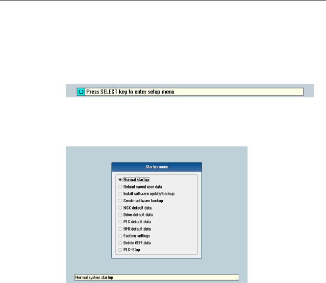
Scope of delivery and requirements 1.4 Starting up the control
1.4Starting up the control
Control startup
Procedure:
1.Switch the control on. The following display then appears during startup:
2.Press the <SELECT> key within three seconds.
3.Then press the following keys in succession:
Menu reset key, HSK2 (horizontal SK2), VSK2 (vertical SK2)
4.The «Setup menu» is displayed, «Normal startup» is the default setting.
Operating modes for startup
|
Selection |
Function |
|
|
Normal startup |
The system carries out a normal startup. |
|
|
Reload saved user data |
The system loads the stored user data («Save data» softkey) |
|
|
from the system CompactFlash card. |
||
|
Install software update/backup |
An update is installed on the system CompactFlash card from |
|
|
the user CompactFlash card or USB FlashDrive. |
||
|
Create software backup |
A backup of the system CompactFlash card is saved to the user |
|
|
CompactFlash card or USB FlashDrive. |
||
|
NCK default data |
The system loads the Siemens NCK data default settings and |
|
|
deletes the retentive data on the PLC. |
||
|
Drive default data |
The SINAMICS user data is deleted. |
|
|
PLC default data |
PLC general reset and load default NOP PLC program. |
|
|
16 |
Turning and Milling |
|
|
Commissioning Manual, 09/2009, 6FC5397-3DP20-0BA0 |

|
Scope of delivery and requirements |
|||
|
1.4 Starting up the control |
|||
|
Selection |
Function |
||
|
HMI default data |
The HMI user data is deleted. |
||
|
Factory settings |
Choice between two cases: No [case 1]/ Yes [case 2] |
||
|
• |
Case 1: |
||
|
The SINAMICS user data is deleted. |
|||
|
Siemens standard NCK data is loaded. |
|||
|
PLC general reset and load default NOP PLC program. |
|||
|
Save HMI user data. |
|||
|
• |
Case 2: |
||
|
As case 1 and additionally: |
|||
|
Deletion of the data in the /oem and /addon directories. |
|||
|
Delete OEM data |
All the data under /oem and /addon is deleted: OEM archives; |
||
|
OEM alarm texts; Easy Screen application. |
|||
|
PLC stop |
PLC is stopped. |
NOTICE
Replacement of the system CompactFlash card between different PPUs
Because of the system-related dependency between the CompactFlash card and SRAM for the data storage in the SINUMERIK 828D, the system CompactFlash card should be considered as a permanently installed EEPROM and should not be replaced!
If this has to be performed for imperative reasons, the replacement of the system CompactFlash card is detected during startup because of the stored serial number.
The reaction of the control is the loading of saved during startup (backup was performed previously with «Save data» softkey). If no stored data is found, a startup is performed automatically with the «NCK default data».
|
Turning and Milling |
17 |
|
Commissioning Manual, 09/2009, 6FC5397-3DP20-0BA0 |
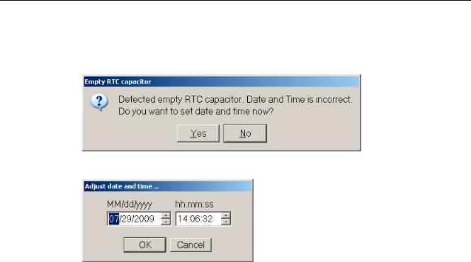
Scope of delivery and requirements 1.4 Starting up the control
Empty RTC capacitor
If the RTC capacitor is discharged, the following message is issued during startup:
You can then reset the date and time:
The capacitor is then charged again when the control is switched on during startup.
|
18 |
Turning and Milling |
|
Commissioning Manual, 09/2009, 6FC5397-3DP20-0BA0 |

Scope of delivery and requirements 1.5 Communication with the control
1.5Communication with the control
Creating the connection
An Ethernet cable is needed to connect the control and PG/PC. The following Ethernet interfaces are available on the control:
●Connection via X127 (behind the flap on the front): Cable type: Crossed Ethernet cable
At interface X127, the control is preset as a DHCP server, delivering the IP address192.168.215.1 for a direct connection (peer-to-peer connection).
●Connection via X130 (at the back): Cable type: Uncrossed Ethernet cable
The interface X130 is the connection to the company network. The IP address that the PG/PC receives here as a DHCP client is determined by the DHCP server from the company network or fixed IP address is entered manually.
1.5.1How to communicate with the control using the Programming Tool
Setting up the communications interface in the Programming Tool
Proceed as follows to set up the network connection in the Programming Tool:
1.Start the Programming Tool.
2.In the navigation bar, click the «Communication» icon or select «View» → «Communication» from the menu.
3.In the left column, under «Communications parameters» enter 192.168.215.1as the IP address for X127.
4.Double click on the icon «TCP/IP» at the top right.
|
Turning and Milling |
19 |
|
Commissioning Manual, 09/2009, 6FC5397-3DP20-0BA0 |

Scope of delivery and requirements
1.5Communication with the control
5.In the dialog «PG/PC interface» select the TCP/IP protocol of the PG/PC. Normally this is the network card of the PC.
Figure 1-2 TCP/IP communications settings
6. Confirm with «OK».
|
20 |
Turning and Milling |
|
Commissioning Manual, 09/2009, 6FC5397-3DP20-0BA0 |
![]()
Scope of delivery and requirements 1.5 Communication with the control
7.Connect by double clicking on the icon «Double click to update». If the connection is made successfully, the icon will be displayed with a green border:
Figure 1-3 Online connection
8.If the connection is unsuccessful, the following setting may have to be deactivated:
Select «Control Panel» → «Network Connections»→ «Local Area Connection» «Properties»→ «Advanced»→ «Windows Firewall» → «Settings»→ «Advanced»: Deactivate the option «Local Area Connection».
|
Turning and Milling |
21 |
|
Commissioning Manual, 09/2009, 6FC5397-3DP20-0BA0 |

Scope of delivery and requirements 1.5 Communication with the control
Figure 1-4 Deactivate option
Confirm with «OK» and repeat Step 7.
|
22 |
Turning and Milling |
|
Commissioning Manual, 09/2009, 6FC5397-3DP20-0BA0 |
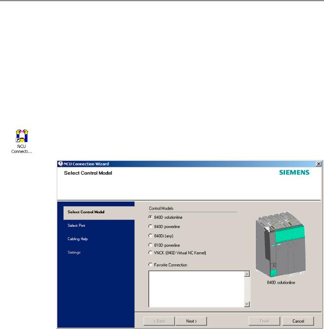
Scope of delivery and requirements 1.5 Communication with the control
1.5.2Example: How to communicate with the control using the NCU Connection Wizard
Requirements
The commissioning software for SINAMICS S120 is installed on the PG/PC. The «NCU Connection Wizard» is part of this software.
The connection to the control has already been set up via the Programming Tool.
Create connection to control
Procedure for the PG/PC:
1.Start the «NCU Connection Wizard» via this link or via the Start menu.
2.In the «Select Control Model» dialog, select «840D solution line» for the NCU type connection to the SINUMERIK 828D.
Figure 1-5 Select the NCU type
|
Turning and Milling |
23 |
|
Commissioning Manual, 09/2009, 6FC5397-3DP20-0BA0 |
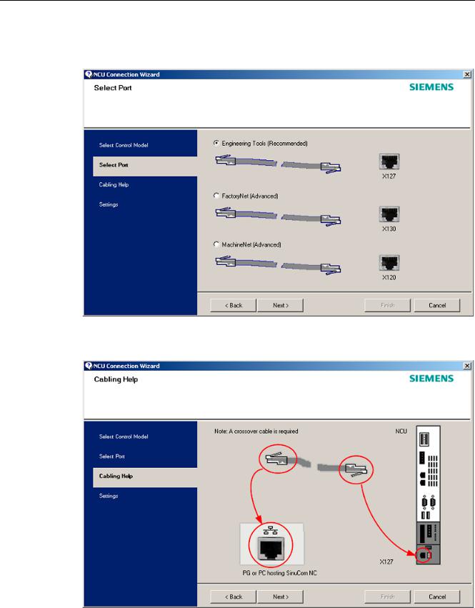
Scope of delivery and requirements
1.5Communication with the control
3.In the «Select Port» dialog, select the connection to the control that you have connected via Ethernet.
Figure 1-6 Select connection
4. Confirm the cable connection for both devices in the»Cabling Help» dialog.
|
Figure 1-7 |
Cabling |
|
24 |
Turning and Milling |
|
Commissioning Manual, 09/2009, 6FC5397-3DP20-0BA0 |
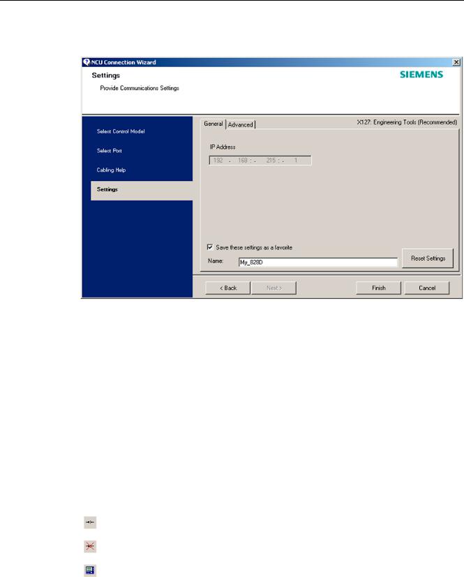
Scope of delivery and requirements 1.5 Communication with the control
5. Check the IP address and enter the name for these settings in the «Settings» dialog.
Figure 1-8 Network settings
1.5.3How to communicate with the control using the RCS Commander
Connection options
The following options are available for the «RCS Commander» to create a connection with the control:
●Direct connection (peer-to-peer)
●Network connection
The current status of the connection is shown at the bottom in the RCS Commander status bar.
Meaning of the buttons:
Connect
Disconnect
Remote control
|
Turning and Milling |
25 |
|
Commissioning Manual, 09/2009, 6FC5397-3DP20-0BA0 |
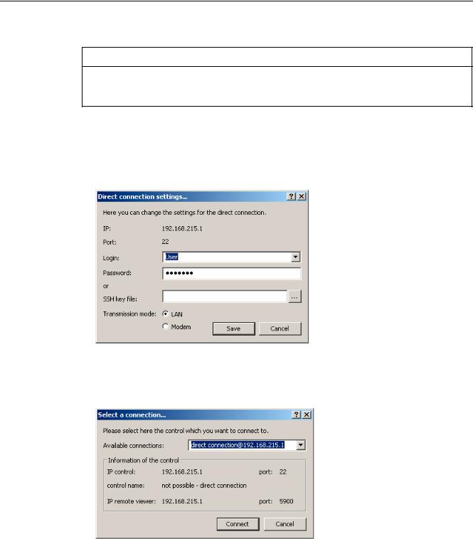
Scope of delivery and requirements 1.5 Communication with the control
NOTICE
Generally only one connection is permitted, i.e. several simultaneous connections to different controls are not supported: So data exchange between two NCUs using «RCS Commander» is not possible.
Direct connection
To create a direct connection:
1. The login data is entered in the dialog «Settings» → «Connection» → «Direct connection»:
Figure 1-9 Dialog: Login data for direct connection
2.In the menu, select «Connection» → «Connect» → «Direct connection» or click the «Connect» button.
The following dialog box is displayed:
Figure 1-10 Dialog: Direct connection
3.The last selected direct connection is highlighted. Using the «Connect» button, a connection to the IP address196.168.215.1 is created.
This dialog does not appear when the direct connection is selected using the menu.
|
26 |
Turning and Milling |
|
Commissioning Manual, 09/2009, 6FC5397-3DP20-0BA0 |
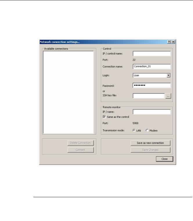
Scope of delivery and requirements 1.5 Communication with the control
Network connection
To create a network connection:
1.In the menu, select «Settings» → «Connection» → «Direct connection» or click the «Connect» button.
Figure 1-11 Dialog: Network connection
2.In the menu, select «Connection» → «Connect» → «Network connection» or select – if available – one of the previously selected connections.
3.Connection is made to the parameterized control.
Note
SSh key file
As an alternative to entering a password, the user may also use an SSh key for authentication. Please refer to the Online Help for more information on this topic.
|
Turning and Milling |
27 |
|
Commissioning Manual, 09/2009, 6FC5397-3DP20-0BA0 |
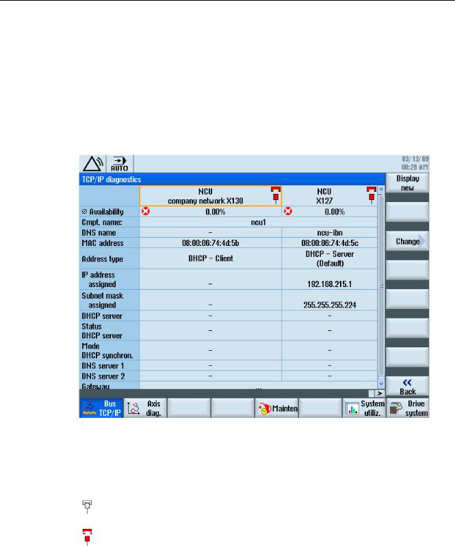
Scope of delivery and requirements 1.5 Communication with the control
1.5.4Communicating with the control via X130
Connection to the company network
The NCU is connected to the company network via the Ethernet interface X130. The company network is used, for example, to access the network drives.
In the «Diagnostics» operating area select the «Bus TCP/IP » → «TCP/IP Diagnostics» → «Details» softkey with the menu forward key in order to set the parameters for the communication via X130.
Figure 1-12 Network settings
Connection properties
Company network X130
|
white |
Network cable inserted |
|
red |
Network cable not inserted |
|
28 |
Turning and Milling |
|
Commissioning Manual, 09/2009, 6FC5397-3DP20-0BA0 |

Scope of delivery and requirements 1.5 Communication with the control
Availability
The availability describes the percentage of faulty data compared to the entire data volume. Problems in the company network (e.g. logical drives that cannot be reached, double IP address, etc.) as well as settling time during power up can result in fluctuations in availability:
|
green |
Greater than 95% |
|
yellow |
50 — 95 % |
|
red |
Less than 50% |
Note
All information that is not available is marked in the relevant table line with a hyphen «-«.
|
Turning and Milling |
29 |
|
Commissioning Manual, 09/2009, 6FC5397-3DP20-0BA0 |

Scope of delivery and requirements 1.5 Communication with the control
|
30 |
Turning and Milling |
|
Commissioning Manual, 09/2009, 6FC5397-3DP20-0BA0 |
![]()
Settings on the HMI |
2 |
2.1Access levels
Access to functions and machine data
The user only has access to information corresponding to a particular access level and the levels below it. The machine data is assigned different access levels.
The access concept controls access to functions and data areas. Access levels 0 to 7 are available, where 0 represents the highest level and 7 the lowest level. Access levels 0 to 3 are locked using a password and 4 to 7 using the appropriate key-operated switch settings.
|
Access level |
Locked by |
Area |
Data class |
|
0 |
— |
System (reserved) |
System (S) |
|
1 |
Password: SUNRISE |
Manufacturer |
Manufacturer (M) |
|
2 |
Password: EVENING |
Servicing |
Individual (I) |
|
3 |
Password: CUSTOMER |
User |
User (U) |
|
4 |
Key-operated switch setting 3 |
Programmer, machine setter |
User (U) |
|
5 |
Key-operated switch setting 2 |
Qualified operator |
User (U) |
|
6 |
Key-operated switch setting 1 |
Trained operator |
User (U) |
|
7 |
Key-operated switch setting 0 |
Semi-skilled operator |
User (U) |
The password remains valid until it is reset with the «Delete Password» softkey. The passwords can be changed after activation.
If, for example, the passwords are no longer known, reinitialization (power up with
«NCK default data») must be carried out. This resets all passwords to the default (see table). POWER ON does not reset the password.
Note
PI LOGOUT
The password can also be deleted via the PLC.
|
Turning and Milling |
31 |
|
Commissioning Manual, 09/2009, 6FC5397-3DP20-0BA0 |

Settings on the HMI 2.1 Access levels
Key-operated switch
Access levels 4 to 7 require a corresponding key-operated switch setting on the machine control panel. Three keys of different colors are provided for this purpose. Each of these keys provides access only to certain areas.
Meaning of the key-operated switch settings:
|
Access level |
Switch setting |
Key color |
|
4-7 |
0 to 3 |
red |
|
5-7 |
0 to 2 |
green |
|
6-7 |
0 and 1 |
black |
|
7 |
0 = Key removal position |
No key inserted |
The key-operated switch setting must always be edited from the PLC user program and applied to the interface accordingly.
|
32 |
Turning and Milling |
|
Commissioning Manual, 09/2009, 6FC5397-3DP20-0BA0 |

Settings on the HMI 2.2 How to set and change the password
2.2How to set and change the password
Set password
To change the access level, select the «Start-up» operating area:
1.Press the «Password» softkey.
2.Press the «Set password» softkey to open the following dialog:
3.Enter a password and confirm this with «OK» or with the <Input> key.
A valid password is acknowledged as set and the currently applicable access level is displayed. Invalid passwords will be rejected.
4.You must delete the old password before activating a password for a lower access level than the one activated.
The last valid password is deleted by pressing the «Delete password» softkey. Then the current key-operated switch setting is valid.
Change password
To change the password:
1. Press the «Change password» softkey to open the following dialog:
Figure 2-2 Change password
2.Enter the new password in both fields and then confirm with the «OK» softkey. If both passwords match, the new password becomes valid and is adopted by the system.
|
Turning and Milling |
33 |
|
Commissioning Manual, 09/2009, 6FC5397-3DP20-0BA0 |

Settings on the HMI
2.3 Available system languages
2.3Available system languages
System languages
In the basic configuration, the SINUMERIK 828D is delivered with the following system languages:
●German
●English
●French
●Italian
●Spanish
●Portuguese (Brazil)
●Chinese (simplified)
●Chinese (traditional)
●Korean
All system languages are installed in the SINUMERIK 828D as delivered, so that a change of language can be carried out directly via the user interface, without having to download system language data.
Note
Additional languages
No CNC option needs to be ordered for the installation of additional languages not included in the scope of delivery.
The language files can be ordered on the DVD Additional Languages for SINUMERIK.
|
34 |
Turning and Milling |
|
Commissioning Manual, 09/2009, 6FC5397-3DP20-0BA0 |

Settings on the HMI 2.4 How to set the date and time
2.4How to set the date and time
Requirement
Changes can only be made with the appropriate access authorization (as of «User» and higher).
Setting the date and time
Procedure:
1.Select the «Start-up» operating area.
2.Press the «HMI» softkey.
3.Press the «Date/Time» softkey. The «Date/Time» window opens.
4.Select the required formats for the date and time in the «Format» field.
5.Confirm the entry with the «OK» softkey.
The new date and time details are accepted and output on the first line in the «current» fields.
|
Turning and Milling |
35 |
|
Commissioning Manual, 09/2009, 6FC5397-3DP20-0BA0 |

Settings on the HMI
2.5 Checking and entering licenses
2.5Checking and entering licenses
Use
The use of the installed system software and the options activated on a SINUMERIK control system require that the licenses purchased for this purpose are assigned to the hardware. In the course of this assignment, a license key is generated from the license numbers of the system software, the options, as well as the hardware serial number. Here, a license database administered by Siemens is accessed via the Internet. Finally, the license information including the license key is transferred to the hardware.
The license database can be accessed using the Web License Manager.
Web License Manager
By using the Web License Manager, you can assign licenses to hardware in a standard Web browser. To conclude the assignment, the license key must be entered manually on the control via the user interface.
The Internet address of the Web License Manager is: http://www.siemens.com/automation/license
Note
SINUMERIK software products
If a license key has not been activated or does not exist for a SINUMERIK software product, alarm 8080 is output by the control.
See also
Definitions for license management (Page 391)
|
36 |
Turning and Milling |
|
Commissioning Manual, 09/2009, 6FC5397-3DP20-0BA0 |

Settings on the HMI 2.5 Checking and entering licenses
2.5.1How to enter a license key
Requirement
The appropriate licenses are required for the activated options. After licensing the options in the Web License Manager, you receive a «license key» containing all options requiring a license and which is only valid for your system CompactFlash card.
To set or reset options, «Manufacturer» access rights are required.
Entering the license key
Procedure:
1.Select the «Start-up» operating area.
2.Press the menu forward key.
3.Press the «Licenses» softkey.
The «Licensing» window opens and gives you the following options:
–Determine the license requirement («All options» and «Missing licenses» softkeys)
–Softkey: «Exp. license requirement»
–Entry line: «Enter license key»
Figure 2-3 Entering the license key
|
Turning and Milling |
37 |
|
Commissioning Manual, 09/2009, 6FC5397-3DP20-0BA0 |

Settings on the HMI
2.5 Checking and entering licenses
2.5.2How to determine the license requirement
Determining the license requirement
Procedure:
1.Press the «All options» softkey to list all the options that can be selected for this control.
2.Activate or deactivate the required options in the «Set» column:
–Mark the checkbox
–Enter the number of options
Options displayed in red are activated, however are not licensed or insufficiently licensed.
— OR —
3.Press the «Missing licenses» softkey to display all options that are activated but not licensed. In the «Set» column, you can deselect the options that you do not require.
Figure 2-4 Licensing (example)
|
38 |
Turning and Milling |
|
Commissioning Manual, 09/2009, 6FC5397-3DP20-0BA0 |

Settings on the HMI 2.5 Checking and entering licenses
4.To activate new selected options, press the «Reset (po)» softkey. A safety prompt appears.
With HMI options, you will need to restart the HMI. Corresponding prompts will appear in the dialog line.
5.Press the «OK» softkey to trigger a warm restart. — OR —
6.Press the «Cancel» softkey to cancel the process.
|
Turning and Milling |
39 |
|
Commissioning Manual, 09/2009, 6FC5397-3DP20-0BA0 |

Settings on the HMI
2.6 Configuring user alarms
2.6Configuring user alarms
Creating user PLC alarms
The PLC alarms in the area from 700 000 — 700 247 are configured by the machine manufacturer. The access level «Manufacturer» is required with the appropriate password.
To enter the user PLC alarms via the user interface, select → «HMI»→ «Alarm texts» in the «Start-up» operating area.
Then you receive the following selection:
|
Alarm texts for |
Name of the xml file |
|
User cycle alarms |
oem_alarms_cycles |
|
User PLC alarms |
oem_alarms_plc |
|
User part program message texts |
oem_partprogram_messages |
Loading user PLC alarms
The alarm text files are only loaded during startup.
●«Alarm» attribute: red, is shown in the «alarm list».
●«Message» attribute: black, is shown under «Messages».
Select <MENU SELECT>, then the menu forward key and press the «HMI restart» softkey to load the alarm texts.
See also
You can find a detailed description of the alarms with system responses and deleting criteria in: SINUMERIK 828D Diagnostics Manual
2.6.1Structure of user PLC alarms
Structure of a user PLC alarm
The user PLC alarms have the following structure:
2LO SUHVVXUH WRR ORZ
|
$ODUP QXPEHU |
9DULDEOH |
$ODUP WH[W |
|
Figure 2-5 |
Alarm structure |
|
|
40 |
Turning and Milling |
|
|
Commissioning Manual, 09/2009, 6FC5397-3DP20-0BA0 |
![]()
Settings on the HMI 2.6 Configuring user alarms
The table below shows the mode of operation of the PLC alarms:
1.The alarm is triggered with the appropriate number and output via the PLC signal.
2.If a variable has been configured to this alarm, the value of this variable is in the specified data word of the PLC variable.
3.The NCK response when the alarm is triggered is defined in the MD14516[x] index (see table below).
4.The alarm text can be freely selected and may be up to 255 characters long.
|
Alarm number |
PLC signal |
PLC variable |
Alarm response |
Alarm text |
|
(MD) |
||||
|
700 000 |
DB1600.DBX0.0 |
DB1600.DBW1000 |
14516[0] |
Alarm 1 |
|
700 001 |
DB1600.DBX0.1 |
DB1600.DBW1004 |
14516[1] |
Alarm 2 |
|
700 002 |
DB1600.DBX0.2 |
DB1600.DBW1008 |
14516[2] |
Alarm 3 |
|
700 003 |
DB1600.DBX0.3 |
DB1600.DBW1012 |
14516[3] |
Alarm 4 |
|
700 004 |
DB1600.DBX0.4 |
DB1600.DBW1016 |
14516[4] |
Alarm 5 |
|
700 005 |
DB1600.DBX0.5 |
DB1600.DBW1020 |
14516[5] |
Alarm 6 |
|
700 006 |
DB1600.DBX0.6 |
DB1600.DBW1024 |
14516[6] |
Alarm 7 |
|
Continuation: |
||||
|
700 247 |
DB1600.DBX30.7 |
DB1600.DBW1988 |
14516[247] |
Alarm 248 |
Defining the NCK response
The following NCK responses are possible:
|
MD14516[x] |
Meaning |
|
Bit 0 |
NC start disabled |
|
Bit 1 |
Read-in disable |
|
Bit 2 |
Feed hold for all axes |
|
Bit 3 |
EMERGENCY STOP |
|
Bit 4 |
PLC in stop |
|
Bit 5 |
Reserved |
|
Bit 6 |
Definition for alarm or message |
|
Bit 6=1: → alarm, Bit 6=0: → message |
|
|
Bit 7 |
POWER ON |
|
Turning and Milling |
41 |
|
Commissioning Manual, 09/2009, 6FC5397-3DP20-0BA0 |

Settings on the HMI
2.6 Configuring user alarms
Configuring alarm texts with variables
The following data types are permitted for variables in the alarm text:
|
Variable |
Meaning |
|
%b |
Binary representation of a 32-bit value |
|
%d |
Integer decimal number |
|
%f |
4 byte floating point number |
|
%i |
Integer decimal number with sign |
|
%o |
Integer octal number |
|
%u |
Unsigned decimal number |
|
%x |
Integer hexadecimal number |
2.6.2How to create user PLC alarms
Notes for processing
The following points should be observed when processing the files:
●The files should be edited externally on a PG/PC with a text editor (e.g. notepad) or with an XML editor. The structure must not be altered.
●The created alarm text files are copied to the the following directory on the CompactFlash card: oem/sinumerik/hmi/lng
●To enable the system to recognize the alarm text file, the file name must be written in lower case letters.
●The alarm text file is converted during system startup: A restart of the HMI is necessary to activate the alarms.
Procedure
To edit a larger number of alarms, first create 2 or 3 alarms directly on the control. Then the file oem_alarms_plc_xxx.ts is created and you have a «document template» with the correct structure, which you can then extend with further alarms. The abbreviation «xxx» stands for the language in which the file has been created.
1.Select the «Start-up» operating area.
2.Press the «HMI» softkey.
3.Press the «Alarm texts» softkey. The «Select file» window appears.
4.Select «oem_alarms_plc» to create user PLC alarm texts.
5.Enter the alarm number in the «Number» field and the desired alarm text in the «Text» field. The alarm numbers and their alarm texts do not have to be consecutive. If an alarm is triggered without a configured text, only the alarm number is specified.
|
42 |
Turning and Milling |
|
Commissioning Manual, 09/2009, 6FC5397-3DP20-0BA0 |

Settings on the HMI 2.6 Configuring user alarms
Searching within the alarm texts
To search for a text or a series of characters:
1.Press the «Find >» softkey. The «Find» window opens; and a new menu is displayed on the vertical softkey bar.
2.Enter the search term in the «Text» field.
3.Place the cursor in the «Direction» field and choose the search direction (forward, backward) with the «SELECT» key.
4.Activate the «Case-sensitive» checkbox when a distinction is to be made between upper and lower case in the entered text.
5.Press the «Find + replace» softkey. The «Find and replace» window appears.
6.Press the «OK» softkey to start the search.
7.Press the «Cancel» softkey to cancel the search.
Other navigation options are:
●Softkey «Go to start»:
The cursor jumps to the first entry of the selected alarm text file
●Softkey «Go to end»:
The cursor jumps to the last entry of the selected alarm text file.
See also
List of language codes used for file names (Page 383)
Example: How to create an online help for user PLC alarms (Page 60)
2.6.3Configuring the alarm log
Logging
Configure the alarm log in the «Diagnostics» operating area.
All alarms and messages are logged in chronological order with their raised and cleared time stamps. The exception are messages of the type «msg» from the NC part program. All alarms and messages that are no longer active when the log is displayed are also retained (historical alarm events).
The alarm log is organized as a ring buffer (default setting). The oldest entries are overwritten with new events in the following cases:
●When the maximum size is exceeded (permissible range: 0 — 32000).
●When the events happened before the last time the system was switched on.
|
Turning and Milling |
43 |
|
Commissioning Manual, 09/2009, 6FC5397-3DP20-0BA0 |

Settings on the HMI
2.6 Configuring user alarms
Permanent backup
To save the alarm log permanently, the alarm log is written to the CompactFlash card.
NOTICE
Saving the alarm log
For permanent storage, the alarm log is written to the CompactFlash card which only allows a limited number of write cycles.
•Therefore, ensure that the backup is only performed when there is a justifiable need!
•Make sure you undo the setting «on every event» if you no longer require storage of the alarm log.
Default: The alarm log is not backed up.
See also
Filtering events: Set up a filter to limit the number of events in the alarm log. You can find more details on this in:
●Commissioning Manual Basesoftware and HMI sl, chapter «Configuring alarms».
●List of the alarm number ranges (Page 384)
2.6.4How to configure the log
Configuring the log
Procedure:
1.Select the «Diagnostics» operating area.
2.Press the «Alarm log» softkey.
3.Press the «Settings» softkey.
4.Enter the desired number in the «Number of entries» field to change the maximum number of raised and cleared events.
Default is 500 events; permissible value range 0 — 32000.
5.Select the type of logging under «File write mode»:
–«Off» if the events are not to be written to a file.
–«On every event» if every event is to be written to a file.
–«Time controlled» if the file is to be overwritten after a particular time interval.
An additional «Time interval» input field appears in which you can specify the time in seconds.
6.Press the «Save log» softkey to save the alarm log.
The settings become effective only after restarting the HMI.
|
44 |
Turning and Milling |
|
Commissioning Manual, 09/2009, 6FC5397-3DP20-0BA0 |

Settings on the HMI 2.6 Configuring user alarms
Editing the configuration file
Procedure:
1.Copy the configuration file «oem_alarmprot_slaesvcconf.xml» from the
/siemens/sinumerik/hmi/template/cfg directory.
2.Insert the file into the directory /oem/sinumerik/hmi/cfg or
/user/sinumerik/hmi/cfg
3.Name the file «slaesvcconf.xml».
4.Open the user-specific file «slaesvcconf.xml» in the editor.
5.Enter the number of events to be output in the <Records type …/> identifier. The default value is 500. The permissible number is in the range from 0 … 32000.
OR:
The number of events to be output and the type of logging can also be entered directly via the user interface:
1.Press the «Alarm log» → «Settings >» softkey in the «Diagnostics» operating area.
As soon as changes are made to the default settings, the «slaesvcconf.xml» file is automatically created in the /user/sinumerik/hmi/cfg directory.
2.Enter the mode of the permanent storage in the <DiskCare type=»int» value=»-1″/> identifier. The following values are possible:
-1: There is no saving of the alarm log (default setting).
0:Each alarm event triggers an immediate saving of the alarm log.
>0: Time for saving the log in seconds:
When there is a change, the log is saved every n > 0 seconds.
3.You adapt the filter for the entry type in the <Filter> identifier. Here the following applies:
–An alarm event is only entered in the log when it satisfies the filter criteria.
–When several filters are defined, these should be linked using the logical operators OR or AND.
The settings become effective only after restarting the HMI.
Note
Number of events
Each incoming or outgoing event of an alarm or message requires a separate entry, even when they belong to the same alarm or message.
Acknowledgement events are also contained in the alarm log. They also require an entry even when they are not recognizable in the alarm log.
|
Turning and Milling |
45 |
|
Commissioning Manual, 09/2009, 6FC5397-3DP20-0BA0 |

Settings on the HMI
2.6 Configuring user alarms
Examples
All alarms that fulfill the following conditions are logged:
● CLEARINFO ≠ 15, therefore without part program messages:
<CONFIGURATION>
<Protocol>
<Filters>
<Siemens_Filter_01 type=»QString» value=»CLEARINFO NOT 15″ /> </Filters>
</Protocol>
</CONFIGURATION>
● «SEVERITY larger than 10» and «smaller than 500» :
<CONFIGURATION>
<Protocol>
<Filters>
<Filter_01 type=»QString» value= «SEVERITY HIGHER 10 AND SEVERTY LOWER 500» />
</Filters>
</Protocol>
</CONFIGURATION>
2.6.5Configuring user alarms with colors
Introduction
For the display of alarms and messages, user specific colors are configured in the alarm attribute file, which are shown in the alarm or message line.
Note
The colors of the tabular overviews of alarms and messages in the «Diagnostics» operating area are permanently set and cannot be changed.
|
46 |
Turning and Milling |
|
Commissioning Manual, 09/2009, 6FC5397-3DP20-0BA0 |

Settings on the HMI 2.6 Configuring user alarms
Copy the following files into the oem, user or addon branch:
●Alarm attribute file: /siemens/sinumerik/hmi/cfg/oem_slaedatabase.xml
To be able to add further colors for alarms and messages at a later point, use the alarm attribute file already available or extend other alarm attribute files.
●Configuration file: /siemens/sinumerik/hmi/cfg/oem_slaesvcconf.xml
In the configuration file, notify the «Alarm&Event Service» of the new alarm attribute file.
Alarm colors
The following attributes for colors can be configured for each alarm number:
|
Identifier <Attribut AttrName= > |
Meaning |
|
TEXTCOLOR |
Font color of the alarm/message text |
|
TEXTBACKGROUNDCOLOR |
Background color of the alarm/message text |
|
NUMBERCOLOR |
Font color of the alarm number |
|
NUMBERBACKGROUNDCOLOR |
Background color of the alarm number |
2.6.6How to configure colors for user alarms
General procedure
The sequence includes the following steps:
●Create alarm attribute file
●Define alarm colors
●Create configuration file
●Trigger restart of the HMI
Create alarm attribute file
Procedure:
1.Copy the alarm attribute file «oem_slaedatabase.xml» as a template from the directory siemens/sinumerik/hmi/template/cfg/
2.Paste the file into one of the following directories: oem/sinumerik/hmi/cfg/oruser/sinumerik/hmi/cfg/
|
Turning and Milling |
47 |
|
Commissioning Manual, 09/2009, 6FC5397-3DP20-0BA0 |

Settings on the HMI
2.6Configuring user alarms
3.Give the file a new name e.g. «alarm_slaedatabase.xml». When assigning a name please note:
–Any name can be chosen but it must be written in lower case letters.
–The name must contain a period and file extension.
Example of the copied file: «alarm_slaedatabase.xml»
<?xml version=»1.0″ encoding=»ISO-8859-1″? <!DOCTYPE SlAeAlarmAttributs> <SlAeAlarmAttributs Version=»01.00.00.00″> <Types>
<Type>
<Category>
<CatDesc>Alarms of the Sinumerk 828 </CatDesc> <Attributes>
<Attribute AttrName=»TEXTCOLOR»
AttrDefault=»5003″ AttrDataType=»10″ > <AttrDesc> Text color of the alarm used
when displayed at the header panel </AttrDesc> </Attribute>
<Attribute AttrName=»TEXTBACKGROUNDCOLOR»
AttrDefault=»5004″ AttrDataType=»10″
<AttrDesc>Background color of the alarm used
when displayed at the header panel </AttrDesc> </Attribute>
<Attribute AttrName=»NUMBERCOLOR»
AttrDefault=»5005″ AttrDataType=»10″
<AttrDesc>Text color of the alarm number used
when displayed at the header panel </AttrDesc> </Attribute>
<Attribute AttrName=»NUMBERBACKGROUNDCOLOR»
AttrDefault=»5006″ AttrDataType=»10″
<AttrDesc>Background color of the alarm number used
when displayed at the header panel </AttrDesc> </Attribute>
</Attributes>
</Category>
</Type>
</Types>
|
48 |
Turning and Milling |
|
Commissioning Manual, 09/2009, 6FC5397-3DP20-0BA0 |

Settings on the HMI 2.6 Configuring user alarms
Define alarm colors
Procedure:
1.Open the created alarm attribute file «alarm_slaedatabase.xml» in the editor.
2.Enter the attribute name of the alarm color type to be changed in the <Attribute AttrName> identifier.
3.Define the alarm source in the identifier <Sources>: SourceID=»51″ SourceURL=»/PLC/PMC»
4.Delete the areas that are not being changed.
5.In the <Alarms> identifier, create a separate area for each individual alarm or for an alarm number range.
6.Enter the alarm number in the <Alarm AlarmID= «…» > identifier, or enter the alarm number range in the <Range FromAlarmID=»…» ToAlarmID= «…»> identifier.
7.Enter the desired color values in the identifiers: <TEXTCOLOR> <TEXTBACKGROUNDCOLOR> <NUMBERCOCLOR> <NUMBERBACKCOLOR>
Note
To insert further alarm sources <Sources>, make sure that the alarm number is always assigned to the correct alarm source.
You can find the SourceID and the SourceURL in the following table: List of the alarm number ranges (Page 384)
Create configuration file
Procedure:
1.Copy the configuration file «oem_slaesvcconf.xml» from the siemens/sinumerik/hmi/template/cfg directory.
2.Insert the file into directory oem/sinumerik/hmi/cfg or user/sinumerik/hmi/cfg.
OR:
3.Press the «HMI» → «Alarm texts >» softkey in the «Start-up» operating area.
As soon as an entry is made, the «alarmtexteditor_db_oem_< … >.xml» file is automatically created in the /oem/sinumerik/hmi/cfg directory.
OR:
4.Edit the «alarmtexteditor_db_oem_< … >.xml»file with an external editor.
5.Transfer the file to the /oem/sinumerik/hmi/cfg directory.
The settings become effective only after restarting the HMI.
|
Turning and Milling |
49 |
|
Commissioning Manual, 09/2009, 6FC5397-3DP20-0BA0 |

Settings on the HMI
2.7 Creating OEM-specific online help
2.7Creating OEM-specific online help
Overview
In addition to the existing system online help, you also have the option of creating a manufacturer-specific online help and adding this to the operator software.
This online help is generated in the HTML format, i.e. it comprises HTML documents that are linked with one another. The subject being searched for is called in a separate window from a contents or index directory. Similar to a document browser (e.g. Windows Explorer), a list of possible selections is displayed in the left-hand half of the window and when you click the required subject, the explanation is displayed in the right-hand half of the window.
Context-sensitive selection of online help pages is not possible. General sequence:
1.Generating HTML files
2.Generating a help book
3.Integrating the online help in the operator software
4.Saving help files in the target system
2.7.1Structure and syntax of the configuration file
Syntax description of the «slhlp.xml»
You require the configuration file «slhlp.xml» to integrate the help book in the existing online help system of the user interface:
|
Tag |
Number |
Meaning |
|||
|
CONFIGURATION |
1 |
Root element of the XML document: Indicates that this |
|||
|
involves a configuration file. |
|||||
|
OnlineHelpFiles |
1 |
Introduces the section of the help books. |
|||
|
<help_book> |
* |
Introduces the section of a help book. |
|||
|
EntriesFile |
File name of the help book with the list of contents and subject |
||||
|
(keyword) entries. |
|||||
|
1 |
Attributes: |
||||
|
value |
Name of the XML file |
||||
|
type |
Data type of the value (QString) |
||||
|
III-Technology |
Specifies the technology for which the help book applies. |
||||
|
«All» applies for all technologies. |
|||||
|
If the help book applies to several technologies, then the |
|||||
|
0,1 |
technologies are listed separated by comma. |
||||
|
Possible values: |
|||||
|
All, Universal, Milling, Turning, Grinding, Stroking, Punching |
|||||
|
Attributes: |
|||||
|
50 |
Turning and Milling |
||||
|
Commissioning Manual, 09/2009, 6FC5397-3DP20-0BA0 |
 Loading…