- Manuals
- Brands
- Suzuki Manuals
- Motorcycle
- DL1000
- Service manual
-
Contents
-
Table of Contents
-
Troubleshooting
-
Bookmarks
Related Manuals for Suzuki DL1000
Summary of Contents for Suzuki DL1000
-
Page 1
DL1000… -
Page 2: Table Of Contents
FOREWORD GROUP INDEX This manual contains an introductory description on the SUZUKI DL1000 and procedures for its inspec- tion/service and overhaul of its main components. GENERAL INFORMATION Other information considered as generally known is not included. Read the GENERAL INFORMATION section to…
-
Page 3: How To Use This Manual
HOW TO USE THIS MANUAL TO LOCATE WHAT YOU ARE LOOKING FOR: 1. The text of this manual is divided into sections. 2. The section titles are listed in the GROUP INDEX. 3. Holding the manual as shown at the right will allow you to find the first page of the section easily.
-
Page 4
Apply molybdenum oil solution. Use fork oil. (Mixture of engine oil and SUZUKl 99000-99001-SS8 MOLY PASTE in a ratio of 1 : 1) Apply SUZUKI SUPER GREASE “A”. Apply or use brake fluid. 99000-25010 Apply SUZUKI MOLY PASTE. Measure in voltage range. -
Page 5: Abbreviations Used In This Manual
ABBREVIATIONS USED IN THIS MANUAL : Engine Control Module ABDC : After Bottom Dead Center Engine Control Unit (ECU) : Alternating Current (FI Control Unit) : Air Cleaner, Air Cleaner Box ECT Sensor : Engine Coolant Temperature : American Petroleum Institute Sensor (ECTS), Water Temp.
-
Page 6
MAL-Code : Malfunction Code (Diagnostic Code) : Maximum : Malfunction Indicator Lamp (LED) : Minimum : Nitrogen Oxides : Over Head Camshaft : Oil Pressure Switch : Positive Crankcase Ventilation (Crankcase Breather) : Right Hand : Read Only Memory : Society of Automotive Engineers STC System : Secondary Throttle Control System (STCS) STP Sensor… -
Page 7
GENERAL INFORMATION GENERAL INFORMATION CONTENTS WARNING/CAUTION/NOTE ……………1- 2 GENERAL PRECAUTIONS …………..1- 2 SUZUKI DL1000K2 (’02-MODEL) …………1- 4 SERIAL NUMBER LOCATION …………1- 4 FUEL, OIL AND ENGINE COOLANT RECOMMENDATION …..1- 4 FUEL ………………..1- 4 ENGINE OIL ……………..1- 5 BRAKE FLUID …………….1- 5 FRONT FORK OIL ……………1- 5… -
Page 8: Warning/Caution/Note
GENERAL INFORMATION WARNING/CAUTION/NOTE Please read this manual and follow its instructions carefully. To emphasize special information, the symbol and the words WARNING, CAUTION and NOTE have special meanings. Pay special attention to the mes- sages highlighted by these signal words. Indicates a potential hazard that could result in death or injury.
-
Page 9
GENERAL INFORMATION » * If parts replacement is necessary, replace the parts with Suzuki Genuine Parts or their equiva- lent. * When removing parts that are to be reused, keep them arranged in an orderly manner so that they may be reinstalled in the proper order and orientation. -
Page 10: Suzuki Dl1000K2 (’02-Model)
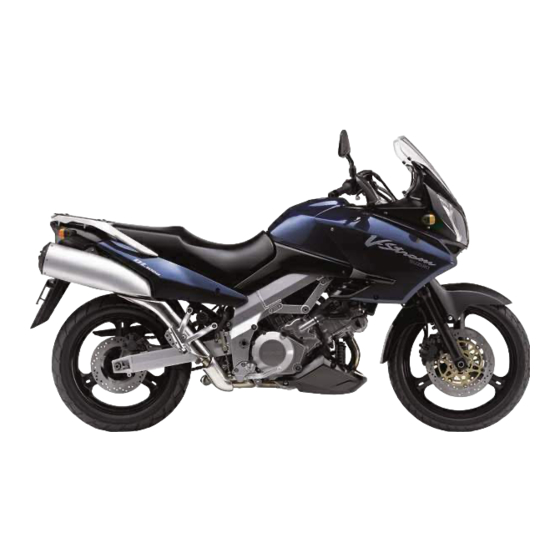
GENERAL INFORMATION SUZUKI DL1000K2 (’02-MODEL) LEFT SIDE RIGHT SIDE * Difference between photographs and actual motorcycles depends on the markets. SERIAL NUMBER LOCATION The frame serial number or V.I.N. (Vehicle Identification Number) 1 is stamped on the right side of the steering head pipe.
-
Page 11: Engine Oil
Suzuki recommends the use of SUZUKI COOLANT anti-freeze/engine coolant. If this is not available, use an equivalent which is compatible with an aluminum radiator.
-
Page 12: Break-Ln Procedures
GENERAL INFORMATION BREAK-lN PROCEDURES During manufacture only the best possible materials are used and all machined parts are finished to a very high standard but it is still necessary to allow the moving parts to “BREAK-IN” before subjecting the engine to maximum stresses.
-
Page 13: Information Labels
GENERAL INFORMATION INFORMATION LABELS Noise label (For E-03, 24, 33) Information label (For E-03, 28, 33) ICES Canada label (For E-28) » Vacuum hose routing label (For E-33) Fuel caution label (For E-02, 24) Manual notice label (For E-03, 33) Tire pressure label &…
-
Page 14: Specifications
GENERAL INFORMATION SPECIFICATIONS DIMENSIONS AND DRY MASS Overall length…………2 295 mm (90.4 in) Overall width …………865 mm (34.1 in) Overall height…………1 335 mm (52.6 in) Wheelbase …………1 535 mm (60.4 in) Ground clearance ……….165 mm ( 6.5 in) Seat height…………
-
Page 15
GENERAL INFORMATION CHASSIS Front suspension……….Inverted telescopic, coil spring, oil damped Rear suspension ……….Link type, coil spring, oil damped Steering angle …………. 40° (right & left) Caster…………..26° 30’ Trail …………..111 mm (4.3 in) Turning radius …………. 2.7 m (8.86 ft) Front brake ………… -
Page 16: Country And Area Codes
1-10 GENERAL INFORMATION COUNTRY AND AREA CODES The following codes stand for the applicable country(-ies) and area(-s). CODE COUNTRY or AREA E-02 U. K. E-03 U. S. A. (Except for California) E-19 E-24 Australia E-28 Canada E-33 California (U. S. A.)
-
Page 17
PERIODIC MAINTENANCE PERIODIC MAINTENANCE CONTENTS PERIODIC MAINTENANCE SCHEDULE ……….2- 2 PERIODIC MAINTENANCE CHART ………..2- 2 LUBRICATION POINTS ……………2- 3 MAINTENANCE AND TUNE-UP PROCEDURES …….2- 4 AIR CLEANER …………….2- 4 SPARK PLUG …………….2- 5 TAPPET CLEARANCE …………..2- 7 FUEL HOSE ……………..2-12 ENGINE OIL AND OIL FILTER …………2-12 ENGINE IDLE SPEED …………..2-14 THROTTLE CABLE PLAY …………2-14… -
Page 18: Periodic Maintenance Schedule
PERIODIC MAINTENANCE PERIODIC MAINTENANCE SCHEDULE The chart below lists the recommended intervals for all the required periodic service work necessary to keep the motorcycle operating at peak performance and economy. Mileages are expressed in terms of kilome- ters, miles and time for your convenience. NOTE: More frequent servicing may be performed on motorcycles that are used under severe conditions.
-
Page 19: Lubrication Points
PERIODIC MAINTENANCE LUBRICATION POINTS Proper lubrication is important for smooth operation and long life of each working part of the motorcycle. Major lubrication points are indicated below. Clutch lever holder Side-stand pivot Footrest pivot Drive chain and spring hook Brake lever holder and throttle cables Brake pedal pivot and footrest pivot…
-
Page 20: Maintenance And Tune-Up Procedures
PERIODIC MAINTENANCE MAINTENANCE AND TUNE-UP PRO- CEDURES This section describes the servicing procedures for each item of the Periodic Maintenance requirements. AIR CLEANER Inspect every 6 000 km (4 000 miles, 6 months) and replace every 18 000 km (11 000 miles, 18 months). •…
-
Page 21: Spark Plug
PERIODIC MAINTENANCE NOTE: When cleaning the air cleaner element, drain water from the air cleaner by removing the drain plug. SPARK PLUG Inspect every 6 000 km (4 000 miles, 6 months) and replace every 12 000 km (7 500 miles, 12 months). NO.1 (FRONT) SPARK PLUG REMOVAL •…
-
Page 22
PERIODIC MAINTENANCE NO.2 (REAR) SPARK PLUG REMOVAL • Remove the seat. (!6-4) • Lift and support the fuel tank. (!4-51) • Remove the spark plug cap. • Remove the spark plug with a spark plug wrench. HEAT RANGE • Check to see the heat range of the plug. Standard Cold type CR8EK… -
Page 23: Tappet Clearance
PERIODIC MAINTENANCE SPARK PLUG AND PLUG CAP INSTALLATION » Before using a spark plug wrench, carefully turn the spark plug by finger into the threads of the cylinder head to prevent damage the aluminum threads. • Install the spark plugs to the cylinder heads by finger tight, and then tighten them to the specified torque.
-
Page 24
PERIODIC MAINTENANCE • Remove the generator cover plug 1 and timing inspection plug 2. • Turn the crankshaft to set the No.1 (Front) cylinder at TDC of compression stroke. (Align the “F | T” line on the generator rotor to the index mark of valve timing inspection hole and also bring the camshafts to the position as shown in page 2-7.) •… -
Page 25
PERIODIC MAINTENANCE TAPPET CLEARANCE ADJUSTMENT The clearance is adjusted by replacing the existing tappet shim by a thicker or thinner shim. • Remove the intake or exhaust camshafts. (!3-20) • Remove the tappet and shim by fingers or magnetic hand. •… -
Page 26
2-10 PERIODIC MAINTENANCE (INTAKE SIDE) -
Page 27
PERIODIC MAINTENANCE 2-11 (EXHAUST SIDE) -
Page 28: Fuel Hose
2-12 PERIODIC MAINTENANCE FUEL HOSE Inspect every 6 000 km (4 000 miles, 6 months). Replace every 4 years. Inspect the fuel feed hose A for damage and fuel leakage. If any defects are found, the fuel hoses must be replaced. ENGINE OIL AND OIL FILTER (ENGINE OIL) Replace initially at 1 000 km (600 miles, 1 month) and…
-
Page 29
Filter change: 2.9 L (3.1/2.6 US/Imp qt) Overhaul engine: 3.3 L (3.5/2.9 US/Imp qt) » ONLY USE A GENUINE SUZUKI MOTORCYCLE OIL FILTER. Other manufacturer’s oil filters may differ in thread specifications (thread diameter and pitch), fil- tering performance and durability which may lead to engine damage or oil leaks. -
Page 30: Engine Idle Speed
2-14 PERIODIC MAINTENANCE ENGINE IDLE SPEED Inspect initially at 1 000 km (600 miles, 1 month) and every 6 000 km (4 000 miles, 6 months) thereafter. NOTE: Make this adjustment when the engine is hot. • Start up the engine and set its idle speed to the specified range by turning the throttle stop screw A.
-
Page 31: Throttle Valve Synchronization
PERIODIC MAINTENANCE 2-15 MAJOR ADJUSTMENT • Remove the fuel tank. (!4-52) • Remove the air cleanet box. (!4-60) • Loosen the locknut 1 of the throttle returning cable. • Turn the returning cable adjuster 2 to obtain proper cable play. •…
-
Page 32: Clutch
2-16 PERIODIC MAINTENANCE CLUTCH (CLUTCH HOSE AND CLUTCH FLUID) Inspect every 6 000 km (4 000 miles, 6 months). Replace hose every 4 years. Replace fluid every 2 years. CLUTCH FLUID LEVEL • Keep the motorcycle upright and place the handlebars straight.
-
Page 33: Cooling System
PERIODIC MAINTENANCE 2-17 COOLING SYSTEM Inspect every 6 000 km (4 000 miles, 6 months). Replace engine coolant every 2 years. ENGINE COOLANT LEVEL CHECK • Keep the motorcycle upright. • Check the engine coolant level by observing the full and lower lines on the engine coolant reserve tank.
-
Page 34
2-18 PERIODIC MAINTENANCE AIR BLEEDING THE ENGINE COOLANT CIRCUIT • Bleed air from the air bleeder bolt 1. • Tighten the air bleeder bolt 1 to the specified torque. & Air bleeder bolt: 13 N·m (1.3 kgf-m, 9.5 lb-ft) • Add engine coolant up to the radiator inlet. •… -
Page 35: Drive Chain
PERIODIC MAINTENANCE 2-19 RADIATOR HOSES Check to see the radiator hoses for crack, damage or engine coolant leakage. If any defects are found, replace the radiator hoses with new ones. DRIVE CHAIN Inspect initially at 1 000 km (600 miles, 1 month) and every 6 000 km (4 000 miles, 6 months) thereafter.
-
Page 36
2-20 PERIODIC MAINTENANCE • Count out 21 pins (20 pitches) on the chain and measure the distance between the two points. If the distance exceeds the service limit, the chain must be replaced. % Drive chain 20-pitch length Service Limit: 319.4 mm (12.6 in) ADJUSTING •… -
Page 37: Brake
* Do not use any oil sold commercially as “drive chain oil”. Such oil can damage the “O”-rings (or seals). * The standard drive chain is RK525SMOZ7. SUZUKI recommends that this standard drive chain should be used for the replacement.
-
Page 38
2-22 PERIODIC MAINTENANCE The brake system of this motorcycle is filled with a glycol-based brake fluid. Do not use or mix different types of fluid such as silicone-based or petro- leum-based. Do not use any brake fluid taken from old, used or unsealed containers. Never re-use brake fluid left over from the last servicing or stored for a long period. -
Page 39
PERIODIC MAINTENANCE 2-23 BRAKE PEDAL HEIGHT • Loosen the locknut 1 and rotate the push rod 2 to locate brake pedal 20 – 30 mm (0.8 – 1.2 in) A below the top face of the footrest. • Retighten the locknut 1 to secure the push rod 2 in the proper position. -
Page 40
2-24 PERIODIC MAINTENANCE AIR BLEEDING THE BRAKE FLUID CIRCUIT Air trapped in the fluid circuit acts like a cushion to absorb a large proportion of the pressure developed by the master cylin- der and thus interferes with the full braking performance of the brake caliper. -
Page 41: Tire
R19M/C (59H) for front and 150/70 R17M/C (69H) for rear. The use of tires other than those specified may cause instability. It is highly recommended to use a SUZUKI Genuine Tire. TIRE TYPE BRIDGESTONE (Front : TW101F Rear : TW152F)
-
Page 42: Front Fork
2-26 PERIODIC MAINTENANCE FRONT FORK Inspect every 12 000 km (7 500 miles, 12 months). Inspect the front forks for oil leakage, scoring or scratches on the outer surface of the inner tubes. Replace any defective parts, if necessary. (!6-15) REAR SUSPENSION Inspect every 12 000 km (7 500 miles, 12 months).
-
Page 43: Chassis Bolt And Nut
PERIODIC MAINTENANCE 2-27 CHASSIS BOLT AND NUT Tighten initially at 1 000 km (600 miles, 1 month) and every 6 000 km (4 000 miles, 6 months) thereafter. Check that all chassis bolts and nuts are tightened to their specified torque. (Refer to page 2-28 for the loca- tions of the following nuts and bolts on the motorcycle.) ITEM N·m…
-
Page 44
2-28 PERIODIC MAINTENANCE… -
Page 45: Compression Pressure Check
PERIODIC MAINTENANCE 2-29 COMPRESSION PRESSURE CHECK The compression of a cylinder is a good indicator of its internal condition. The decision to overhaul the cylinder is often based on the results of a compression test. Periodic mainte- nance records kept at your dealership should include compression readings for each maintenance service. COMPRESSION PRESSURE SPECIFICATION (Automatic de-comp.
-
Page 46: Oil Pressure Check
2-30 PERIODIC MAINTENANCE OIL PRESSURE CHECK Check periodically the oil pressure in the engine to judge roughly the condition of the moving parts. OIL PRESSURE SPECIFICATION Above 400 kPa (4.0 kgf/cm², 57 psi) at 3 000 r/min., Oil temp. at 60°C (140°F) Below 700 kPa (7.0 kgf/cm², 100 psi) If the oil pressure is lower or higher than the specification, the following causes may be considered.
-
Page 47
ENGINE ENGINE CONTENTS ENGINE COMPONENTS REMOVABLE WITH ENGINE IN PLACE …3- 2 ENGINE REMOVAL AND INSTALLATION ………3- 3 ENGINE REMOVAL …………..3- 3 ENGINE INSTALLATION ………….3-12 ENGINE DISASSEMBLY …………..3-19 ENGINE TOP SIDE …………..3-19 ENGINE BOTTOM SIDE …………..3-25 ENGINE COMPONENTS INSPECTION AND SERVICING ….3-34 CYLINDER HEAD COVER …………3-34 CAMSHAFT/CYLINDER HEAD ………..3-35 CYLINDER/PISTON INSPECTION ……….3-47… -
Page 48: Engine Components Removable With Engine In Place
ENGINE ENGINE COMPONENTS REMOVABLE WITH ENGINE IN PLACE The parts listed below can be removed and reinstalled without removing the engine from the frame. Refer to the page listed in this section for removal and reinstallation instructions. ENGINE LEFT SIDE PARTS REMOVAL INSTALLATION…
-
Page 49: Engine Removal And Installation
ENGINE ENGINE REMOVAL AND INSTALLATION ENGINE REMOVAL Before taking the engine out of the frame, wash the engine using a steam cleaner. Engine removal is sequentially explained in the following steps. Reinstall the engine by reversing the removal procedure. • Drain engine oil. (!2-12) •…
-
Page 50
ENGINE • Remove the fuel tank 1. • Remove the air cleaner. • Remove the throttle body. • Remove the spark plug caps. • Remove the camshaft position sensor lead wire coupler 1. • Disconnect the gear position switch lead wire coupler 2. -
Page 51
ENGINE • Disconnect the generator lead wire coupler 1 and signal gen- erator lead wire coupler 2 by removing the screw A. • Remove the gearshift lever link. • Remove the engine coolant temperature sensor lead wire coupler 3. • Bind the clutch lever with a rubber band to prevent the clutch release cylinder piston from coming out. -
Page 52
ENGINE • Remove the push rod 1. • Remove the engine sprocket cover 2. • Remove the speed sensor 3. • Remove the engine sprocket nut and washer while depress- ing the brake pedal. • Remove the cotter pin. (For E-03, 28, 33) •… -
Page 53
ENGINE • Disconnect the engine ground lead wire 1. sensor lead wire couplers 2, 3. • Disconnect the O ² • Remove the mufflers. (L & R) • Loosen the front exhaust pipe mounting bolts. -
Page 54
ENGINE • Remove the front exhaust pipe. • Remove the mud guard 1. • Remove the rear exhaust pipe. • Remove the right footrest bracket and brake pedal. • Remove the oil cooler 2. • Disconnect the starter motor lead wire 3 and oil pressure switch lead wire 4. -
Page 55
ENGINE • Support the engine with an engine jack. • Remove the engine mounting nut 1 and bolt. • Loosen the engine mounting thrust adjuster lock nut with the special tool. » 09940-14990: Engine mounting thrust adjuster socket wrench • Loosen the engine mounting thrust adjuster. «… -
Page 56
3-10 ENGINE • Remove the ignition coil lead wires. • Remove the engine mounting nut 1. • Loosen the engine mounting thrust adjuster lock nut. » 09940-14990: Engine mounting thrust adjuster socket wrench • Loosen the engine mounting thrust adjuster 2. •… -
Page 57
ENGINE 3-11 • Gradually lower the engine assembly by removing the bolt 1, Be careful not to damage the frame and engine when removing the engine from the frame. -
Page 58: Engine Installation
3-12 ENGINE ENGINE INSTALLATION Remount the engine in the reverse order of engine removal. Pay attention to the following points: NOTE: * The engine mounting nuts are self-locking. * Once the nut has been removed, it is no longer of any use. Be sure to use new nuts, and then tighten them to the specified torque.
-
Page 59
ENGINE 3-13 • Before installing the engine assembly, install the spacer A, collar B and engine thrust adjuster C, D. • Install the collar B onto the crankcase properly as shown. • Apply THREAD LOCK “1342” to the engine mounting bracket bolts. -
Page 60
3-14 ENGINE • Put the drive chain on the driveshaft. • Gradually raise the engine assembly and align all the bolt holes. • Install the engine mounting bolts and bracket bolts, and tighten them temporarily. • Tighten the engine mounting thrust adjuster and its lock nut to the specified torque with the special tool. -
Page 61
ENGINE 3-15 • Tighten the engine mounting nut A, B to the specified torque. $ Engine mounting nut A: 75 N·m (7.5 kgf-m, 54.0 lb-ft) Engine mounting nut B: 55 N·m (5.5 kgf-m, 40.0 lb-ft) • After tightening the bolt C, tighten the pinch bolt D to the specified torque. -
Page 62
3-16 ENGINE ITEM N·m kgf-m lb-ft 16.5 • Adjust the brake pedal height. & Brake pedal height A Standard: 20 – 30 mm (0.8 – 1.2 in) • Install the gearshift arm as shown. & Gearshift arm angle A: Approx. 60°… -
Page 63
• Tighten the speed sensor rotor bolt to the specified torque. » Speed sensor rotor bolt: 18 N·m (1.8 kgf-m, 13.0 lb-ft) • Apply SUZUKI SUPER GREASE “A” to the push rod 1 and install it. • Install the clutch release cylinder. -
Page 64
3-18 ENGINE • After installing the engine, route the wire harness, cables and hoses properly. (!8-14) • Adjust the following items. * Engine oil !2-12 * Engine coolant !2-17 * Engine idle speed !2-14 * Throttle cable play !2-14 & Engine oil capacity Oil change: 2.7 L (2.9/2.4 US/lmp qt) Oil and filter change: 2.9 L (3.1/2.6 US/lmp qt) -
Page 65: Engine Disassembly
ENGINE 3-19 ENGINE DISASSEMBLY ENGINE TOP SIDE • Remove the thermostat. • Remove the valve timing inspection plug 1 and generator cover plug 2. FRONT CYLINDER HEAD COVER • Remove the front cylinder head cover 1. • Turn the crankshaft to bring the “F | T” line on generator rotor to the index mark of the valve inspection hole and also to bring the cams to the position as shown.
-
Page 66
3-20 ENGINE FRONT CYLINDER CAMSHAFT • Remove the camshaft journal holders. Be sure to loosen the camshaft journal holder bolts evenly by shifting the wrench diagonally. • Remove the camshafts. NOTE: Do not drop the dowel pins into the crankcase. FRONT CAM CHAIN TENSION ADJUSTER •… -
Page 67
ENGINE 3-21 STARTER MOTOR • Remove the starter motor. • Remove the cylinder head nut. • Loosen the cylinder nuts. • Remove the oil cooler mounting bracket 1. • Remove the cylinder head bolts. • Remove the cylinder head. NOTE: * When loosening the cylinder head bolts, loosen each bolt little by little diagonally. -
Page 68
3-22 ENGINE • Remove the cylinder base gasket and dowel pins. FRONT PISTON • Place a clean rag over the cylinder base so as not to drop the piston pin circlip into the crankcase. • Remove the piston pin circlip. •… -
Page 69
ENGINE 3-23 Pull the front cam chain upward, or the chain will be caught between the crankcase and cam drive idle gear/sprocket when turning the crankshaft. REAR CYLINDER CAMSHAFT • Remove the two camshaft journal holders. Be sure to loosen the camshaft journal holder bolts evenly by shifting the wrench diagonally. -
Page 70
3-24 ENGINE • Remove the cylinder head bolts and cam chain tensioner mounting bolt. • Remove the cam chain tensioner. • Remove the cylinder head nuts 1. • Remove the cylinder head nut 2. • Loosen the cylinder nuts 3. •… -
Page 71: Engine Bottom Side
ENGINE 3-25 • Remove the cylinder base gasket and dowel pins. REAR PISTON • Place a clean rag over the cylinder base so as not to drop the piston pin circlip into the crankcase. • Remove the piston pin circlip. •…
-
Page 72
3-26 ENGINE • Remove the bushings 1 from the crankcase and generator cover. CLUTCH COVER • Remove the water pump case. WATER PUMP DISASSEMBLY !5-13 CLUTCH • Remove the clutch cover. • Hold the generator rotor with the special tool. «… -
Page 73
ENGINE 3-27 • Remove the clutch push piece, bearing and thrust washer. • Remove the clutch push rod 1. • Remove the clutch drive and driven plates. • Remove the wave washer 2 and wave washer seat 3. • Unlock the clutch sleeve hub nut. •… -
Page 74
3-28 ENGINE • Remove the washer 1 and 2. • Remove the clutch sleeve hub 3. • Remove the thrust washer 4. • Remove the primary driven gear assembly. • Remove the needle roller bearing, spacer and thrust washer. GEAR POSITION SWITCH •… -
Page 75
ENGINE 3-29 OIL SUMP FILTER • Remove the oil sump filter. OIL PUMP • Remove the oil pump driven gear 1 by removing the snap ring. » 09900-06107: Snap ring pliers • Remove the pin 2 and washer 3. NOTE: Do not drop the snap ring, pin and washer into the crankcase. -
Page 76
3-30 ENGINE • Insert a suitable bar into the holes of primary drive gears to align the teeth of scissors gears. • Remove the cam drive idle gear/sprocket and cam chain. • Remove the key 1. PRIMARY DRIVE GEAR • Hold the generator rotor with the special tool. «… -
Page 77
ENGINE 3-31 • Remove the key 1 and thrust washer 2. GENENRATOR ROTOR • While holding the generator rotor with the special tool, remove its bolt. » 09930-44541: Rotor holder • Install the special tool to the boss. • Remove the generator rotor by turning the special tool while holding the generator rotor with the special tool. -
Page 78
3-32 ENGINE • Draw out the gearshift shaft 1. • Remove the gearshift cam plate 2. • Remove the gearshift cam stopper 3. • Remove the engine sprocket spacer 4. • Remove the cam drive idle gear shaft 5. • Remove the crankcase bolts. -
Page 79
ENGINE 3-33 • Separator the crankcase into 2 parts, right and left with the crankcase separating tool. » 09920-13120: Crankcase separating tool NOTE: * Fit the crankcase separating tool, so that the tool arms are in parallel with the side of crankcase. * The crankshaft and transmission components should remain in the left crankcase half. -
Page 80: Engine Components Inspection And Servicing
• If the carbon deposit is found in the reed valve, replace it with a new one. REASSEMBLY • Apply SUZUKI SUPER GREASE “A” to the O-ring and install ‘ 99000-25030: SUZUKI SUPER GREASE “A” (USA) 99000-25010: SUZUKI SUPER GREASE “B” (Others) •…
-
Page 81: Camshaft/Cylinder Head
ENGINE 3-35 CAMSHAFT/CYLINDER HEAD Be sure to identify each removed part as to its loca- tion, and lay the parts out in groups designated as “No.1”, “No.2”, “Exhaust”, “Intake”, so that each will be restored to the original location during assembly. CAMSHAFT “FRONT”…
-
Page 82
3-36 ENGINE CAMSHAFT JOURNAL WEAR Determine whether or not each journal is worn down to the limit by measuring the oil clearance with the camshaft installed in place. Use the plastigauge A to read the clearance at the widest portion, which is specified as follows: &… -
Page 83: Camshaft Runout
ENGINE 3-37 CAMSHAFT RUNOUT Measure the runout with a dial gauge. Replace the camshaft if the runout exceeds the limit. & Camshaft runout Service Limit (IN & EX): 0.10 mm (0.004 in) » 09900-20607: Dial gauge (1/100 mm, 10 mm) 09900-20701: Magnetic stand 09900-21304: V-block (100 mm) CAM GEAR AND AUTOMATIC-DECOMP.
-
Page 84
3-38 ENGINE CYLINDER HEAD • Remove the tappets and shims 1 by fingers or magnetic hand. • Using special tools, compress the valve spring and remove the two cotter halves 2 from the valve stem. » 09916-14510: Valve lifter 09916-14910: Valve lifter attachment 09916-84511: Tweezers •… -
Page 85
ENGINE 3-39 • Remove the oil seals 1 and the spring seats 2. Do not reuse the removed oil seals. CYLINDER HEAD DISTORTION Decarbonize the combustion chambers. Check the gasketed surface of the cylinder head for distortion with a straightedge and thickness gauge, taking a clearance reading at several places indicated. -
Page 86
3-40 ENGINE VALVE FACE WEAR Visually inspect each valve for wear of its seating face. Replace any valve with an abnormally worn face. The thickness T decreases as the wear of the face advances. Measure the thickness and, if the thickness is found to have been reduced to the limit, replace it. -
Page 87
ENGINE 3-41 • Re-finish the valve guide holes in cylinder head with the reamer and handle. » 09916-34580: Valve guide reamer 09916-34542: Reamer handle • Oil the stem hole, too, of each valve guide and drive the guide into the guide hole with the valve guide installer and attach- ment. -
Page 88
3-42 ENGINE • The ring-like dye impression left on the valve face must be continuous without any break. In addition, the width of the dye ring, which is the visualized seat “width”, must be within the following specification: & Valve seat width W Standard: 0.9 –… -
Page 89
ENGINE 3-43 If the contact area is too high on the valve, or if it is too wide, use Contact area too high and too the 15°/60° cutters (for exhaust side) and 30°/60° cutters (for wide on face of valve intake side) to lower and narrow the contact area. -
Page 90
3-44 ENGINE VALVE SPRING The force of the coil spring keeps the valve seat tight. Weak- ened spring results in reduced engine power output, and often account for the chattering noise coming from the valve mecha- nism. Check the valve springs for proper strength by measuring their free length and also by the force required to compress them. -
Page 91
ENGINE 3-45 If the thrust clearance exceeds the standard range, adjust the thrust clearance by the following procedures: • Remove the thrust washer, and measure its thickness with a micrometer. • Change the thrust washer with the other washer if the thrust clearance is incorrect. -
Page 92
3-46 ENGINE • Install the valve spring with the small-pitch portion A facing cylinder head. Paint B: Large-pitch portion UPWARD • Put on the valve spring retainer, and using the valve lifter, press down the spring, fit the cotter halves to the stem end, and release the lifter to allow the cotter 1 to wedge in between retainer and stem. -
Page 93: Cylinder/Piston Inspection
• When installing the intake pipe, apply grease to the O-ring. NOTE: “UP” mark faces upward. ‘ 99000-25030: SUZUKI SUPER GREASE ‘‘A’’ (USA) 99000-25010: SUZUKI SUPER GREASE ‘‘A’’ (Others) Use the new O-ring to prevent air from sucking through the joint.
-
Page 94: Piston Diameter
3-48 ENGINE CYLINDER BORE Inspect the cylinder wall for any scratches, nicks or other dam- age. Measure the cylinder bore diameter at six places. & Cylinder bore Standard: 98.000 – 98.015 mm (3.8583 – 3.8589 in) » 09900-20508: Cylinder gauge set PISTON DIAMETER Using a micrometer, measure the piston outside diameter at 10 mm (0.4 in) from the piston skirt end.
-
Page 95: Piston Ring Thickness
ENGINE 3-49 PISTON RING TO GROOVE CLEARANCE Using a thickness gauge, measure the side clearances of the 1st and 2nd rings. If any of the clearances exceeds the limit, replace both piston and piston rings. & Piston ring to groove clearance Service Limit (1st) : 0.18 mm (0.0071 in) (2nd) : 0.15 mm (0.0059 in) &…
-
Page 96: Conrod/Crankshaft
3-50 ENGINE PISTON PIN AND PIN BORE Using a small bore gauge, measure the piston pin bore inside diameter, and using a micrometer, measure the piston pin out- side diameter. If the difference between these two measure- ments is more than the limits, replace both piston and piston pin. &…
-
Page 97
ENGINE 3-51 & Conrod big end width Standard: 21.95 – 22.00 mm (0.864 – 0.866 in) & Crank pin width Standard: 44.17 – 44.22 mm (1.739 – 1.741 in) » 09900-20205: Micrometer (0 – 25 mm) CONROD-CRANK PIN BEARING INSPECTION •… -
Page 98
3-52 ENGINE • Remove the caps and measure the width of compressed plas- tigauge with envelope scale. This measurement should be taken at the widest part. & Conrod big end oil clearance Service Limit: 0.080 mm (0.0031 in) • If oil clearance exceeds the service limit, select the specified bearings from the bearing selection table. -
Page 99
ENGINE 3-53 Bearing thickness Color code Color (Part No.) Thickness Green 1.476 – 1.480 mm (12164-02F11-0A0) (0.0581 – 0.0583 in) Black 1.480 – 1.484 mm (12164-02F11-0B0) (0.0583 – 0.0584 in) Brown 1.484 – 1.488 mm (12164-02F11-0C0) (0.0584 – 0.0586 in) Yellow 1.488 –… -
Page 100: Clutch
3-54 ENGINE • When fitting the conrods on the crankshaft, make sure that I.D. codes A of the conrods face each cylinder intake valve sides. Never reuse the bearing cap bolt. Apply engine oil to the bearing cap bolts. 35 N·m 3.5 kgf-m •…
-
Page 101
ENGINE 3-55 CLUTCH DRIVEN PLATES NOTE: Wipe off engine oil from the clutch driven plates with a clean rag. Measure each driven plate for distortion with a thickness gauge and surface plate. Replace driven plates which exceed the limit. & Driven plate distortion Service Limit: 0.10 mm (0.004 in) Measuring distortion «… -
Page 102: Transmission
3-56 ENGINE TRANSMISSION CONSTRUCTION 1st driven gear 5th driven gear » 4th driven gear 3rd driven gear 6th driven gear 2nd driven gear & Drive shaft Countershaft 5th drive gear 3rd & 4th drive gear 6th drive gear 2nd drive gear…
-
Page 103
ENGINE 3-57 DISASSEMBLY Be sure to identify each removed part as to its loca- tion, and lay the parts out in groups designated as “Drive” and “Driven”, so that each will be restored to the original location during assembly. Countershaft •… -
Page 104
3-58 ENGINE Driveshaft • Remove the low driven gear 1 and washer 2. • Remove the low driven gear bushing 3, washer 4 and 5th driven gear 5. • Remove the snap ring with the special tool. » 09900-06107: Snap ring pliers •… -
Page 105
ENGINE 3-59 • Remove the washer 1. • Remove the top driven gear 2 by removing the snap ring. » 09900-06107: Snap ring pliers • Remove the snap ring with the special tool. » 09900-06107: Snap ring pliers • Remove the 2nd driven gear 3, its bushing 4 and washer 5. REASSEMBLY Assemble the transfer in the reverse order of disassembly. -
Page 106
3-60 ENGINE • When installing a new snap ring, pay attention to the direction of the snap ring. Fit it to the side where the thrust is as shown Thrust in the figure. Sharp edge When installing the 3rd and 4th driven gear bushings on to the driveshaft, align the shaft oil holes A with the bushing oil hole B. -
Page 107
ENGINE 3-61… -
Page 108: Gearshift Fork
3-62 ENGINE GEARSHIFT FORK GEARSHIFT FORK TO GROOVE CLEARANCE Using a thickness gauge, check the gearshift fork clearance in the groove of its gear. The clearance for each gearshift fork plays an important role in the smoothness and positiveness of the shifting action. &…
-
Page 109: Primary Drive Gear
ENGINE 3-63 PRIMARY DRIVE GEAR PRIMARY DRIVE GEAR INSPECTION Visually inspect the gear teeth for wear and damage. If they are worn, replace the gear with a new one. PRIMARY DRIVE GEAR DISASSEMBLY • Disassemble the primary drive gear by removing the snap ring 1.
-
Page 110: Starter Torque Limiter
3-64 ENGINE • Install the snap ring 1 completely with the special tool. » 09900-06107: Snap ring pliers * Never reuse a snap ring. * When installing a new snap ring, care must be taken not to expand the end gap larger than required to slip a snap ring over the gear.
-
Page 111: Starter Clutch
ENGINE 3-65 STARTER CLUTCH DISASSEMBLY • Remove the starter clutch securing bolts by holding the rotor with the special tool. » 09930-44541: Rotor holder REASSEMBLY • Install the starter clutch in the proper direction. NOTE: * When installing the starter clutch onto the rotor, face the flange side A of the one way clutch to the rotor.
-
Page 112: Gearshift
3-66 ENGINE GEARSHIFT GEARSHIFT SHAFT/GEARSHIFT ARM DISASSEMBLY • Remove the following parts from the gearshift shaft/gearshift arm 1. 2 Washer 6 Plate return spring 3 Snap ring 7 Washer 4 Gearshift shaft return spring 8 Snap ring 5 Gearshift cam drive plate 9 Washer «…
-
Page 113
OIL PRESSURE SWITCH • Remove the oil pressure switch 1. • When installing the oil pressure switch, apply SUZUKI BOND “1215” to the thread. $ Oil pressure switch: 14 N·m (1.4 kgf-m, 10.0 lb-ft) + 99000-31110: SUZUKI BOND “1215”… -
Page 114
3-68 ENGINE • Remove the oil jet with a suitable bar. • Remove the oil jet. Check the oil jets for clogging. If they are clogged, clean their oil passage with a proper wire or compressed air. • Fit the new O-ring to the oil jet. Use the new O-ring to prevent oil leakage. -
Page 115
ENGINE 3-69 • Apply engine oil to the new O-ring and install it. • Apply THREAD LOCK “1342” to the screw and tighten it to the specified torque. $ Piston cooling oil nozzle screw: 8 N·m (0.8 kgf-m, 6.0 lb-ft) % 99000-32050: THREAD LOCK “1342”… -
Page 116
3-70 ENGINE • Remove the oil seal. The removed oil seal must be replaced with a new one. • Remove the oil seal with the special tool. » 09913-50121: Oil seal remover The removed oil seal must be replaced with a new one. •… -
Page 117: Crankcase-Crankshaft Bearing
ENGINE 3-71 • Install the bearing retainers. NOTE: When installing the bearing retainers, apply THREAD LOCK to the screws. % 09900-32050: THREAD LOCK “1342” • Install the oil seals with the special tool. » 09913-70210: Bearing installer set • Install the oil seal retainer. CRANKCASE-CRANKSHAFT BEARING CRANKCASE-CRANKSHAFT BEARING INSPECTION •…
-
Page 118
3-72 ENGINE CRANKCASE-CRANKSHAFT BEARING SELECTION Select the specified bearings from the crankcase bore I.D. code. The crankcase bore I.D. code A “A”, “B” or “C”, is stamped on the inside of each crankcase half. Bearing selection table I.D. code A I.D. -
Page 119
ENGINE 3-73 • Gradually press out the bearing with the special tool by using the hand-press. Hand-press The removed bearings must be replaced with new Bearing Crankcase ones. NOTE: Bearing Using the hand-press is recommended to remove the crankshaft journal bearings. However, the crankshaft journal bearings can be removed by using with the following special tools. -
Page 120
3-74 ENGINE • Tighten the special tool bolt to the specified torque. $ Special tool bolt: 23 N·m (2.3 kgf-m, 16.5 lb-ft) Before installing the bearings, lightly shave off the sharp edge part of the crankcase chamfer by using an oilstone and wash the crankcase bore with enough engine oil. -
Page 121
1 stops the special tool 2. » 09913-60230: Journal bearing remover/installer Hand-press Bearing Bearing Use the new special tool A (09913-60230) for DL1000. The tool A and B differ in length C. For DL1000 For TL1000S/R (09913-60230) (09913-60210) -
Page 122
3-76 ENGINE • After installing the bearings, check the bearing surface for any scratch or damage. -
Page 123: Generator Cover
• Install the new oil seal with the special tool. » 09913-70210: Bearing installer set NOTE: Apply grease to the oil seal lip to prevent damage when install- ing the gearshift cover. ‘ 99000-25030: SUZUKI SUPER GREASE “A” (USA) 99000-25010: SUZUKI SUPER GREASE “A” (Others)
-
Page 124: Engine Reassembly
3-78 ENGINE ENGINE REASSEMBLY Reassemble the engine in the reverse order of disassembly. NOTE: Apply engine oil to each running and sliding part before reas- sembling. ENGINE BOTTOM SIDE CRANKSHAFT • Install the crankshaft into the left crankcase half. NOTE: Coat lightly molybdenum oil solution to the crankshaft journal bearings.
-
Page 125
99000-25010: SUZUKI SUPER GREASE “A” (Others) Use the new O-ring to prevent oil leakage. • Clean the mating surfaces of the left and right crankcase halves. • Apply SUZUKI BOND “1215” to the mating surface of the left crankcase. + 99000-31110: SUZUKI BOND ‘‘1215’’ NOTE: Use of SUZUKI BOND “1215”… -
Page 126
* The grooved A side of the engine sprocket spacer faces crankcase side. * Apply grease to the oil seal lip and O-ring. ‘ 99000-25030: SUZUKI SUPER GREASE ‘‘A’’ (USA) 99000-25010: SUZUKI SUPER GREASE ‘‘A’’ (Others) GEARSHIFT • Install the gearshift cam stopper 2, its bolt 3, washer 4 and return spring 5. -
Page 127
ENGINE 3-81 • Confirm the gearshift cam stopper movement. • Check the neutral position. • Install the gearshift cam stopper plate after aligning the gear- shift cam pin A with the gearshift cam stopper plate hole B. • Apply a small quantity of THREAD LOCK “1342” to the gear- shift cam stopper plate bolt 1 and tighten it to the specified torque. -
Page 128
* Fit the clamp to the bolt A. * Apply grease to the oil seal lip before installing the gearshift cover. ‘ 99000-25030: SUZUKI SUPER GREASE ‘‘A’’ (USA) 99000-25010: SUZUKI SUPER GREASE ‘‘A’’ (Others) GENERATOR ROTOR • Install the cam drive idle gear shaft 1. -
Page 129
ENGINE 3-83 • While holding the generator rotor with the special tool, tighten the bolt to the specified torque. $ Generator rotor bolt: 160 N·m (16.0 kgf-m, 115.5 lb-ft) » 09930-44541: Rotor holder PRIMARY DRIVE GEAR • Install the thrust washer onto the crankshaft. NOTE: The grooved side A of the thrust washer faces the crankcase side. -
Page 130
3-84 ENGINE • Hold the generator rotor with the special tool. » 09930-44541: Rotor holder • While holding the generator rotor, tighten the primary drive gear nut to the specified torque. $ Primary drive gear nut: 115 N·m (11.5 kgf-m, 83.0 lb-ft) •… -
Page 131
ENGINE 3-85 • Hold the generator rotor with the special tool. » 09930-44541: Rotor holder • While holding the generator rotor, tighten the cam drive idle gear/sprocket nut to the specified torque. $ Cam drive idle gear/sprocket nut: 70 N·m (7.0 kgf-m, 50.5 lb-ft) Before tightening the cam drive idle gear/sprocket nut, be sure to engage the front and rear cam chains to each sprocket. -
Page 132
3-86 ENGINE • Install the gear position switch and cable guide. OIL PUMP DRIVEN GEAR • Install the washer 1 and pin 2. • Install the oil pump driven gear by installing the snap ring. » 09900-06107: Snap ring pliers NOTE: The boss A of the oil pump driven gear faces crankcase side. -
Page 133
ENGINE 3-87 • Install the primary driven gear assembly 1 onto the counter- shaft. NOTE: * When installing the primary driven gear assembly, align the teeth of the primary drive gears by inserting a suitable bar to the holes of them. * Be sure to engage the oil pump drive and driven gears, pri- mary drive and driven gears. -
Page 134
3-88 ENGINE • Lock the clutch sleeve hub nut with a center punch. • Install the spring washer seat 1 and spring washer 2 onto the clutch sleeve hub correctly. • Insert the clutch drive plates and driven plates one by one into the clutch sleeve hub in the prescribed order, No.3 drive plate being inserted first. -
Page 135
ENGINE 3-89 Direction of outside NOTE: *The No.2 Driven plate should be installed between 4th to 7th position from the clutch sleeve hub. *Set the numbers of driven plate to the standard specifications when replacing the driven plates with the new ones. DRIVEN PLATE: No.1 Driven plate…5 –… -
Page 136
* Install the bracket D. • Fit the dowel pin. • Apply the grease to the O-ring. ‘ 99000-25030: SUZUKI SUPER GREASE ‘‘A’’ (USA) 99000-25010: SUZUKI SUPER GREASE ‘‘A’’ (Others) • Install the water pump case. • Install the starter idle gear 1, spacer 2 and shaft 3. -
Page 137
ENGINE 3-91 • Install the bushings A into the crankcase and generator cover. NOTE: Apply molybdenum oil solution to the inside of the bushings. ) MOLYBDENUM OIL • Fit the washers onto the starter torque limiter. • Install the starter torque limiter. •… -
Page 138: Engine Top Side
3-92 ENGINE OIL FILTER • Apply engine oil lightly to the O-ring. • Install the oil filter turning it by hand until feeling that the O-ring contacts the mounting surface. Then tighten it 2 turns with the special tool. » 09915-40610: Oil filter wrench •…
-
Page 139
ENGINE 3-93 • Position the gaps of the three rings as shown. Before inserting each piston into the cylinder, check that the gaps are so located. • 2nd ring 120˚ • Lower side • Upper side rail rail 120˚ 120˚ •… -
Page 140
• Apply engine oil to the new O-rings. • Install each of the oil jets. Use the new O-rings to prevent oil leakage. CYLINDER • Coat SUZUKI BOND “1215” lightly to the mating surfaces at the parting line between the right and left crankcases as shown. FRONT NOTE: When replacing the stud bolt A, apply SUZUKI BOND “1215”… -
Page 141
ENGINE 3-95 • Hold the piston rings in proper position, and insert each of the pistons into the respective cylinders. NOTE: When installing the cylinders, keep the cam chains taut. The cam chain must not be caught between cam drive sprocket and crankcase when turning the crankshaft. -
Page 142
3-96 ENGINE NOTE: * Install the washers to the cylinder head bolts (M10) as shown. * Apply engine oil to the washers and thread portion of the bolts before installing the cylinder head bolts. • After firmly tightening the cylinder head bolts (M10), install the cylinder head nuts and bolts. -
Page 143
ENGINE 3-97 • Place the front cylinder head on the cylinder. NOTE: When installing the cylinder head, keep the cam chain taut. • Tighten the cylinder head bolts (M10) to the specified two-step torque with a torque wrench sequentially and diago- nally. -
Page 144
3-98 ENGINE • Pull the cam chains upward and install the cam chain tension- ers into each cylinder head. 1 For No.1 (Front) cylinder head 2 For No.2 (Rear) cylinder head NOTE: * When installing the cam chain tensioners, insert the their holder ends A into each guide cast on the cylinder. -
Page 145
ENGINE 3-99 FRONT CAM DRIVE IDLE GEAR/SPROCKET • Turn the crankshaft counterclockwise with the box wrench and align “F I T” line A on the generator rotor with the index mark B of the valve timing inspection hole while keeping the camshaft drive chain pulled upward. -
Page 146
3-100 ENGINE • Check and correct the positions of the “F I T” line on the gen- erator rotor and cam drive idle gear/sprocket 1. When checking the positions, remove the cam chain slack at the cam chain guide 2 side by holding the cam drive idle gear/sprocket by hand. -
Page 147
ENGINE 3-101 NOTE: When checking the cam drive idle gear/sprocket 1 position at its gear tooth, top or root, bring the eye level as shown in right illustration. 6˚ • Tighten the cam drive idle gear/sprocket shaft to the specified torque. -
Page 148
3-102 ENGINE • Compress the cam chain tension adjuster rod 1 fully by releasing the ratchet 2. Push • From this position, turn out the cam chain tension adjuster bolt 3 until locking the cam chain tension adjuster rod 1. Now the cam chain tension adjuster is ready to install. -
Page 149
ENGINE 3-103 • Install the cam chain tension adjuster as shown and tighten its mounting bolts to the specified torque. $ Cam chain tension adjuster mounting bolt: 10 N·m (1.0 kgf-m, 7.0 lb-ft) • Release the cam chain tension adjuster by turning in its bolt NOTE: Click sound is heard when the cam chain tension adjuster rod is released. -
Page 150
NOTE: Apply grease to the O-ring before installing. ‘ 99000-25030: SUZUKI SUPER GREASE ‘‘A’’ (USA) 99000-25010: SUZUKI SUPER GREASE ‘‘A’’ (Others) $ Cam chain tension adjuster bolt (Rear): 7 N·m (0.7 kgf-m, 5.0 lb-ft) -
Page 151
ENGINE 3-105 CAMSHAFT • Rotate the generator rotor 720 degrees (2 turns) and align the “F I T” line on the generator rotor with the index mark of the valve timing inspection hole. • Recheck the position of the engraved lines A on the front and rear cam drive idle gears/sprockets. -
Page 152
3-106 ENGINE NOTE: “EXF” “INF” “EXR” “INR” The cam shafts are identified by the engraved letters. 1 No.1 (Front) exhaust camshaft 2 No.1 (Front) intake camshaft 3 No.2 (Rear) exhaust camshaft 4 No.2 (Rear) intake camshaft NOTE: Before placing the camshafts on cylinder head, apply molybde- num oil solution to their journals and cam faces. -
Page 153
ENGINE 3-107 • Install the camshaft journal holders, intake and exhaust. • Fasten the camshaft journal holders evenly by tightening the camshaft journal holder bolts sequentially and diagonally. (Try to equalize the pressure by shifting the wrench in the above manner, to fasten the shafts evenly.) NOTE: * Damage to head or camshaft journal holder thrust surfaces… -
Page 154
3-108 ENGINE NO.2 (REAR) CAMSHAFTS • Install the No.2 (Rear) camshafts, intake and exhaust, in the following procedure. • From the position where the No.1 (Front) camshafts have now been installed, rotate the generator rotor 360 degrees (1 turn) and align the “F I T” line on the generator rotor with the index mark of the valve timing inspection hole. -
Page 155
ENGINE 3-109 • Install the camshaft journal holders, intake and exhaust. • Fasten the camshaft journal holders evenly by tightening the camshaft journal holder bolts sequentially and diagonally. (Try to equalize the pressure by shifting the wrench in the above manner, to fasten the shafts evenly.) NOTE: * Damage to head or camshaft journal holder thrust surfaces… -
Page 156
3-110 ENGINE • After installing the No.2 (Rear) camshafts, rotate the genera- tor rotor 360 degrees (1 turn), and recheck the positions of the camshafts. Be sure to check the positions of the “F I T” line A on the generator rotor, engraved line B on the cam drive idle gears/sprockets and the engraved line C on the camshafts. -
Page 157
Be sure to check the tappet clearance. CYLINDER HEAD COVER • Install the new gaskets ( 2, 3) to each cylinder head cover. • Apply SUZUKI BOND “1207B” to the cam end caps of the gaskets as shown. , 99000-31140: SUZUKI BOND “1207B”… -
Page 158
• Install the new O-ring to the starter motor. Use the new O-ring to prevent oil leakage. • Apply grease to the O-ring. ‘ 99000-25030: SUZUKI SUPER GREASE ‘‘A’’ (USA) 99000-25010: SUZUKI SUPER GREASE ‘‘A’’ (Others) • Install the starter motor. -
Page 159: Fi System
FI SYSTEM CONTENTS PRECAUTIONS IN SERVICING …………..4- 2 CONNECTOR/COUPLER …………..4- 2 FUSE …………………. 4- 3 ECM/VARIOUS SENSORS …………..4- 3 ELECTRICAL CIRCUIT INSPECTION PROCEDURE ……4- 5 USING TESTERS ………………. 4- 8 FI SYSTEM TECHNICAL FEATURES …………4- 9 INJECTION TIME (INJECTION VOLUME) ……….
-
Page 160
FI SYSTEM FUEL TANK LIFT-UP …………….4-51 FUEL TANK REMOVAL ……………..4-52 FUEL TANK INSTALLATION …………..4-52 FUEL PRESSURE INSPECTION …………4-53 FUEL PUMP INSPECTION …………..4-54 FUEL PUMP RELAY INSPECTION …………4-55 FUEL PUMP AND FUEL FILTER REMOVAL ……..4-55 FUEL MESH FILTER INSPECTION AND CLEANING ……4-57 FUEL PUMP AND FUEL MESH FILTER INSTALLATION ….4-57 THROTTLE BODY AND STV ACTUATOR ………….4-59 CONSTRUCTION ……………….4-59… -
Page 161: Precautions In Servicing
FI SYSTEM PRECAUTIONS IN SERVICING When handling the FI component parts or servicing the FI sys- tem, observe the following points for the safety of the system. CONNECTOR/COUPLER • When connecting a connector, be sure to push it in until a click is felt.
-
Page 162: Fuse
FI SYSTEM • When connecting meter probe from the terminal side of the coupler (connection from harness side not being possible), use extra care not to force and cause the male terminal to bend or the female terminal to open. Connect the probe as shown to avoid opening of female ter- minal.
-
Page 163
FI SYSTEM Ignition S/W • When disconnecting and connecting the ECM couplers, make sure to turn OFF the ignition switch, or electronic parts may get damaged. • Battery connection in reverse polarity is strictly prohibited. INCORRECT Such a wrong connection will damage the components of the FI system instantly when reverse power is applied. -
Page 164: Electrical Circuit Inspection Procedure
FI SYSTEM ELECTRICAL CIRCUIT INSPECTION PROCEDURE While there are various methods for electrical circuit inspection, described here is a general method to check for open and short circuit using an ohmmeter and a voltmeter. OPEN CIRCUIT CHECK Possible causes for the open circuit are as follows. As the cause can exist in the connector/coupler or terminal, they need to be checked carefully.
-
Page 165
FI SYSTEM Continuity check • Measure resistance across coupler B (between A and C in the figure). If no continuity is indicated (infinity or over limit), the circuit is open between terminals A and C. • Disconnect the coupler B and measure resistance between ’… -
Page 166
FI SYSTEM SHORT CIRCUIT CHECK (WIRE HARNESS TO GROUND) • Disconnect the negative cable from the battery. To other • Disconnect the connectors/couplers at both ends of the circuit parts to be checked. NOTE: If the circuit to be checked branches to other parts as shown, disconnect all connectors/couplers of those parts. -
Page 167: Using Testers
FI SYSTEM USING TESTERS • Use the Suzuki multi-circuit tester (09900-25008). • Use well-charged batteries in the tester. • Be sure to set the tester to the correct testing range. Using the tester MULTI-CIRCUIT TESTER • Incorrectly connecting the + and — probes may cause the inside of the tester to burnout.
-
Page 168: Fi System Technical Features
FI SYSTEM FI SYSTEM TECHNICAL FEATURES INJECTION TIME (INJECTION VOLUME) The factors to determine the injection time include the basic fuel injection time which is calculated on the basis of the intake air pressure, engine speed and throttle opening angle, and various compensations. These compensations are determined according to the signals from various sensors that detect the engine and driving conditions.
-
Page 169: Compensation Of Injection Time (Volume)
4-10 FI SYSTEM COMPENSATION OF INJECTION TIME (VOLUME) The following different signals are output from the respective sensors for compensation of the fuel injection time (volume). SIGNAL DESCRIPTION ATMOSPHERIC PRESSURE SENSOR When atmospheric pressure is low, the sensor sends the SIGNAL signal to the ECM and reduce the injection time (volume).
-
Page 170: Fuel Delivery System
FI SYSTEM 4-11 FUEL DELIVERY SYSTEM The fuel delivery system consists of the fuel tank, fuel pump, fuel filters, fuel feed hose, fuel delivery pipe (including fuel injectors) and fuel pressure regulator. There is no fuel return hose. The fuel in the fuel tank is pumped up by the fuel pump and pressurized fuel flows into the injector installed in the fuel delivery pipe.
-
Page 171: Fuel Pump
4-12 FI SYSTEM FUEL PUMP The electric fuel pump is mounted at the bottom of the fuel tank, which consists of the armature, magnet, impeller, brush, check valve and relief valve. The ECM controls its ON/OFF operation as controlled under the FUEL PUMP CONTROL SYSTEM.
-
Page 172: Fuel Pressure Regulator
FI SYSTEM 4-13 FUEL PRESSURE REGULATOR The fuel pressure regulator consists of the spring and valve. It keeps absolute fuel pressure of 300 kPa (3.0 kgf/cm , 43 psi) to be applied to the injector at all times. When the fuel pressure rises more than 300 kPa (3.0 kgf/cm , 43 psi), the fuel pushes the valve in the regu- lator open and excess fuel returns to the fuel tank.
-
Page 173: Fuel Pump Control System
4-14 FI SYSTEM FUEL PUMP CONTROL SYSTEM When the ignition switch is turned on, current from the battery flows to the fuel pump motor through the side- stand relay and the fuel pump relay causing the motor to turn. Since the ECM has a timer function, the fuel pump motor stops turning in three seconds after the switch has been turned on.
-
Page 174: Ecm (Fi Control Unit)
FI SYSTEM 4-15 ECM (FI CONTROL UNIT) The ECM is located under the seat. The ECM consists of CPU (Central Processing Unit), memory (ROM) and I/O (Input/Output) sections. The signal from each sensor is sent to the input section and then sent to CPU. On the basis of signal information received, CPU calculates the volume of fuel necessary for injection using maps programmed for varying engine conditions.
-
Page 175: Sensors
4-16 FI SYSTEM SENSORS INTAKE AIR PRESSURE SENSOR (IAP SENSOR) The intake air pressure sensor is located at the rear side of the air cleaner box and its vacuum hose is connected to the throttle body. The sensor detects the intake air pressure, which is then con- verted into voltage signal and sent to the ECM.
-
Page 176
FI SYSTEM 4-17 CRANKSHAFT POSITION SENSOR (CKP SENSOR) The signal rotor is mounted on the left end of the crankshaft, and the crankshaft position sensor (Pick-up coil) is installed in the generator cover. The sensor generates the pick-up signal to be supplied to the ECM. -
Page 177
4-18 FI SYSTEM ENGINE COOLANT TEMPERATURE SENSOR (ECT SENSOR) The engine coolant temperature sensor is installed at the ther- mostat case. The sensor detects the engine oil temperature in thermistor resistance value, which is then converted to voltage signal and sent to the ECM. -
Page 178
FI SYSTEM 4-19 TIP OVER SENSOR (TO SENSOR) The tip over sensor is located above the AP sensor. The sensor detects the leaning of the motorcycle. When it leans more than 65°, the mechanical switch turns ON and a signal is sent to the ECM. -
Page 179: Fi System Parts Location
4-20 FI SYSTEM FI SYSTEM PARTS LOCATION Atomospheric pressure sensor (APS) Speedometer Crankshaft position sensor (CKPS) Secondary throttle position sensor (STPS) Speed sensor Throttle position sensor (TPS) Fuel pump (FP) Secondary throttle valve actuator (STVA) Ignition coil (IG COIL) Tip over sensor (TOS) Fuel pump relay (FP RELAY)
-
Page 180
FI SYSTEM 4-21 Gear position switch Intake air temperature sensor (IATS) Heated oxygen sensor (HO Intake air pressure sensor (IAPS) PAIR solenoid valve Camshaft position sensor (CMPS) Fuel injector (FI) Engine coolant temperature sensor (ECTS) -
Page 181: Fi System Wiring Diagram
4-22 FI SYSTEM FI SYSTEM WIRING DIAGRAM…
-
Page 182: Self-Diagnosis Function
FI SYSTEM 4-23 SELF-DIAGNOSIS FUNCTION The self-diagnosis function is incorporated in the ECM. The function has two modes, “User mode” and “Dealer mode”. The user can only be notified by the LCD (DISPLAY) panel and LED (FI light). To check the function of the individual FI system devices, the dealer mode is prepared.
-
Page 183: Dealer Mode
4-24 FI SYSTEM DEALER MODE The defective function is memorized in the computer. Use the special tool’s coupler to connect to the dealer mode coupler. The memorized malfunction code is displayed on LCD (DISPLAY) panel. Malfunction means that the ECM does not receive signal from the devices. These affected devices are indicated in the code form.
-
Page 184: Tps Adjustment
FI SYSTEM 4-25 CODE MALFUNCTION PART REMARKS None No defective part Camshaft position sensor (CMPS) Crankshaft position sensor (CKPS) Pick-up coil signal, signal generator Intake air pressure sensor (IAPS) Throttle position sensor (TPS) Engine coolant temp. sensor (ECTS) Intake air temp. sensor (IATS) Atmospheric pressure sensor (APS) Tip over sensor (TOS) Ignition signal #1 (IG coil #1)
-
Page 185: Fail-Safe Function
4-26 FI SYSTEM FAIL-SAFE FUNCTION FI system is provided with fail-safe function to allow the engine to start and the motorcycle to run in a mini- mum performance necessary even under malfunction condition. ITEM FAIL-SAFE MODE STARTING ABILITY RUNNING ABILITY Intake air pressure sensor Intake air pressure is “YES”…
-
Page 186: Fi System Troubleshooting
FI SYSTEM 4-27 FI SYSTEM TROUBLESHOOTING CUSTOMER COMPLAINT ANALYSIS Record details of the problem (failure, complaint) and how it occurred as described by the customer. For this purpose, use of such an inspection form will facilitate collecting information to the point required for proper analysis and diagnosis.
-
Page 187
4-28 FI SYSTEM MOTORCYCLE/ENVIRONMENTAL CONDITION WHEN PROBLEM OCCURS Environmental condition Weather Fair Cloudy Rain Snow Always Other Temperature Warm Cool Cold ( °F/ °C) Always Frequency Always Sometimes ( times/ day, month) Only once Under certain condition Road Urban Suburb Highway Mountainous ( Uphill… -
Page 188: Self-Diagnostic Procedures
FI SYSTEM 4-29 SELF-DIAGNOSTIC PROCEDURES • Don’t disconnect couplers from ECM, battery cable from bat- tery, ECM ground wire harness from engine or main fuse before confirming malfunction code (self-diagnostic trouble code) stored in memory. Such disconnection will erase mem- orized information in ECM memory.
-
Page 189: Malfunction Code And Defective Condition
4-30 FI SYSTEM MALFUNCTION CODE AND DEFECTIVE CONDITION MALFUNCTION DETECTED FAILURE CONDITION DETECTED ITEM CODE CHECK FOR NO FAULT ––––––––––– Camshaft position sen- The signal does not reach ECM for more than 3 sec. after receiving the starter signal. The camshaft position sensor wiring and mechanical parts. (Camshaft position sensor, intake cam pin, wiring/coupler con- nection) Crankshaft position…
-
Page 190
FI SYSTEM 4-31 Secondary throttle When no actuator control signal is supplied from the ECM or valve actuator communication signal does not reach ECM or operation voltage does not reach STVA motor, C28 is indicated. STVA can not operate. STVA lead wire/coupler. The sensor should produce following voltage. -
Page 191: C11″ Cmp Sensor Circuit Malfunction
4-32 FI SYSTEM “C11” CMP SENSOR CIRCUIT MALFUNCTION DETECTED CONDITION POSSIBLE CAUSE No CMP sensor signal for 3 seconds at engine • Metal particles or foreign material being attached cranking. on the CMP sensor and rotor tip. • CMP sensor circuit open or short. •…
-
Page 192: C12″ Ckp Sensor Circuit Malfunction
FI SYSTEM 4-33 “C12” CKP SENSOR CIRCUIT MALFUNCTION DETECTED CONDITION POSSIBLE CAUSE No CKP sensor signal for 3 seconds at engine • Metal particles or foreign material being attached cranking. on the CKP sensor and rotor tip. • CKP sensor circuit open or short. •…
-
Page 193: C13″ Iap Sensor Circuit Malfunction
4-34 FI SYSTEM “C13” IAP SENSOR CIRCUIT MALFUNCTION DETECTED CONDITION POSSIBLE CAUSE Low pressure and low voltage. • Clogged vacuum passage between throttle body High pressure and high voltage. and IAP sensor. < • Air being drawn from vacuum passage between 0.10 V Sensor voltage 4.80 V…
-
Page 194
FI SYSTEM 4-35 Remove the IAP sensor. Connect the vacuum pump gauge to the vacuum port of the IAP sensor. Arrange 3 new 1.5 V batteries in series (check that total voltage is 4.5 – 5.0 V) and connect terminal to the ground terminal and terminal to the Vcc terminal. -
Page 195: C14″ Tp Sensor Circuit Malfunction
4-36 FI SYSTEM “C14” TP SENSOR CIRCUIT MALFUNCTION DETECTED CONDITION POSSIBLE CAUSE Signal voltage low or high. • TP sensor maladjusted. Difference between actual throttle opening and open- • TP sensor circuit open or short. ing calculated by ECM in larger than specified value. •…
-
Page 196
FI SYSTEM 4-37 Connect the TP sensor/injector coupler Insert the copper wires to the lead wire coupler. Turn the ignition switch ON. Measure the TP sensor output voltage at the coupler (between P/W and B/Br wires) by turning the throttle grip. B/Br B/Br TP sensor output voltage… -
Page 197: C15″ Ect Sensor Circuit Malfunction
4-38 FI SYSTEM “C15” ECT SENSOR CIRCUIT MALFUNCTION DETECTED CONDITION POSSIBLE CAUSE High engine coolant temp. (Low voltage – Low • B/Bl circuit shorted to ground. resistance) • B/Br circuit open. Low engine coolant temp. (High voltage – High • ECT sensor malfunction. resistance) •…
-
Page 198: C21″ Iat Sensor Circuit Malfunction
FI SYSTEM 4-39 “C21” IAT SENSOR CIRCUIT MALFUNCTION DETECTED CONDITION POSSIBLE CAUSE High intake air temp. (Low voltage – Low resis- • Dg circuit shorted to ground. tance) • B/Br circuit open. Low intake air temp. (High voltage – High resis- •…
-
Page 199: C22″ Ap Sensor Circuit Malfunction
4-40 FI SYSTEM “C22” AP SENSOR CIRCUIT MALFUNCTION DETECTED CONDITION POSSIBLE CAUSE Low pressure and low voltage. • Clogged air passage with dust. High pressure and high voltage. • Red wire circuit open or shorted to ground. < • B/Br or G/Y wire circuit shorted to ground. 0.10 V Sensor voltage 4.80 V…
-
Page 200
FI SYSTEM 4-41 Remove the AP sensor. Connect the vacuum pump gauge to the air passage port of the AP sensor. Arrange 3 new 1.5 V batteries in series (check that total voltage is 4.5 – 5.0 V) and connect terminal to the ground terminal and terminal to the Vcc terminal. -
Page 201: C23″ To Sensor Circuit Malfunction
4-42 FI SYSTEM “C23” TO SENSOR CIRCUIT MALFUNCTION DETECTED CONDITION POSSIBLE CAUSE No TO sensor signal for more than 4 seconds, • TO sensor circuit open or short. after ignition switch turns ON. • TO sensor malfunction. Sensor voltage high. •…
-
Page 202: C24″ Or «C25» Ignition System Malfunction
FI SYSTEM 4-43 “C24” or “C25” IGNITION SYSTEM MALFUNCTION *REFER TO THE IGNITION SYSTEM FOR DETAILS. (#7-19) “C28” STV ACTUATOR CIRCUIT MALFUNCTION DETECTED CONDITION POSSIBLE CAUSE The operation voltage does not reach the STVA. • STVA malfunction. ECM does not receive communication signal from •…
-
Page 203: C29″ Stp Sensor Circuit Malfunction
4-44 FI SYSTEM “C29” STP SENSOR CIRCUIT MALFUNCTION DETECTED CONDITION POSSIBLE CAUSE Signal voltage low or high. • STP sensor maladjusted. Difference between actual throttle opening and • STP sensor circuit open or short. opening calculated by ECM in larger than specified •…
-
Page 204
FI SYSTEM 4-45 Turn the ignition switch OFF. Connect the STP sensor coupler. Insert the copper wires to the lead wire coupler. Yellow Disconnect the STVA lead wire coupler. Turn the ignition switch ON. Measure the STP sensor output voltage at the coupler B/Br (between Yellow and B/Br wires) by turning the secondary throttle valve (close and open) with a finger. -
Page 205: C31″ Gear Position (Gp) Switch Circuit Malfunction
4-46 FI SYSTEM “C31” GEAR POSITION (GP) SWITCH CIRCUIT MALFUNCTION DETECTED CONDITION POSSIBLE CAUSE No Gear Position switch voltage • Gear Position switch circuit open or short. Switch voltage low. • Gear Position switch malfunction. • ECM malfunction. Switch Voltage > 1.0 V without the above value.
-
Page 206: C32″ Or «C33» Fuel Injection Malfunction
FI SYSTEM 4-47 “C32” or “C33” FUEL INJECTION MALFUNCTION DETECTED CONDITION POSSIBLE CAUSE No injector current. • Injector circuit open or short. • Injector malfunction. • ECM malfunction. INSPECTION • Remove the fuel tank and air cleaner box. ( : 4-52 and -60) Turn the ignition switch OFF.
-
Page 207: C41″ Fp Relay Circuit Malfunction
4-48 FI SYSTEM “C41” FP RELAY CIRCUIT MALFUNCTION DETECTED CONDITION POSSIBLE CAUSE No signal from fuel pump relay. • Fuel pump relay circuit open or short. • Fuel pump relay malfunction. • ECM malfunction. INSPECTION • Remove the seat. ( 6-4) Turn the ignition switch OFF.
-
Page 208: C44″ Ho
FI SYSTEM 4-49 “C44” HO SENSOR (HO S) CIRCUIT MALFUNCTION DETECTED CONDITION POSSIBLE CAUSE Output voltage of HO Sensor higher than the spec- • HO sensor or its circuit open or short. ification or lower than the specification. • Fuel system malfunction. •…
-
Page 209
4-50 FI SYSTEM Turn the ignition switch OFF. Insert the copper wire to the ECM lead wire coupler terminal terminal (Heater circuit). Turn the ignition switch ON and measure the heater voltage between terminal and ground. If the tester voltage indicates the battery voltage for few seconds it is good condition. -
Page 210: Fuel System
FI SYSTEM 4-51 FUEL SYSTEM FUEL TANK LIFT-UP • Remove the seat. (#6-4) • Remove the fuel tank side covers, left and right. • Remove the cowling fitting bolts, left and right. • Remove the fuel tank top cover by removing the bolts and fas- teners.
-
Page 211: Fuel Tank Removal
4-52 FI SYSTEM FUEL TANK REMOVAL • Lift and support the fuel tank with the fuel tank prop stay. (#4-51) • Disconnect the fuel pump lead wire coupler 1. • Place a rag under the fuel feed hose and disconnect the feed hose 2 from the fuel tank.
-
Page 212: Fuel Pressure Inspection
FI SYSTEM 4-53 FUEL PRESSURE INSPECTION • Lift and support the fuel tank with the fuel tank prop stay. (#4-51) • Place a rag under the fuel feed hose. (#4-52) • Remove the fuel feed hose and install the special tools between the fuel tank and fuel delivery pipe.
-
Page 213: Fuel Pump Inspection
4-54 FI SYSTEM FUEL PUMP INSPECTION Turn the ignition switch ON and check that the fuel pump oper- ates for few seconds. If the fuel pump motor does not make operating sound, replace the fuel pump assembly or inspect the fuel pump relay and tip over sensor.
-
Page 214: Fuel Pump Relay Inspection
FI SYSTEM 4-55 FUEL PUMP RELAY INSPECTION Fuel pump relay is located behind the ECM. • Remove the seat. • Remove the fuel pump relay. First, check the insulation between 1 and 2 terminals with pocket tester. Then apply 12 volts to 3 and 4 terminals, + to 3 and — to 4, and check the continuity between 1 and 2.
-
Page 215
4-56 FI SYSTEM • Remove the screws. • Remove the fuel pump assy from the fuel pump plate. • Remove the fuel pump holder. • Remove the fuel mesh filter. • Remove the fuel pressure regulator holder 1 and the fuel pressure regulator 2. -
Page 216: Fuel Mesh Filter Inspection And Cleaning
FI SYSTEM 4-57 FUEL MESH FILTER INSPECTION AND CLEANING If the fuel mesh filter is clogged with sediment or rust, fuel will not flow smoothly and loss in engine power may result. Blow the fuel mesh filter with compressed air. NOTE: If the fuel mesh filter is clogged with many sediment or rust, replace the fuel filter cartridge with a new one.
-
Page 217
• Install the new O-ring and apply grease to it. The O-ring must be replaced with a new one to prevent fuel leakage. & 99000-25030: SUZUKI SUPER GREASE “A” (USA) 99000-25010: SUZUKI SUPER GREASE “A” (Others) • When installing the fuel pump assembly, first tighten all the… -
Page 218: Throttle Body And Stv Actuator
FI SYSTEM 4-59 THROTTLE BODY AND STV ACTUATOR CONSTRUCTION 5 N . m Intake pipe side (0.5 kgf-m, 3.7 lb-ft) Forward 3 N . m VIEW OF TOP 0.3 kgf-m, 2.0 lb-ft 15˚ – 25˚ Air cleaner side 15˚ – 25˚ 5 N .
-
Page 219: Throttle Body Removal
4-60 FI SYSTEM THROTTLE BODY REMOVAL • Remove the fuel tank. (#4-52) • Loosen the respective throttle body clamp screws (air cleaner side). • Disconnect the *PAIR solenoid valve lead wire coupler, IAP senor coupler and IAT sensor coupler. • Disconnect the PAIR hoses from the PAIR solenoid valve. •…
-
Page 220: Throttle Body Disassembly
FI SYSTEM 4-61 • Disconnect the throttle cables from their drum. • Dismount the throttle body assembly. » * Be careful not to damage the throttle cable bracket and fast idle lever when dismounting or remounting the throttle body assembly. * After disconnecting the throttle cables, do not snap the throttle valve from full open to full close.
-
Page 221
4-62 FI SYSTEM • Remove the fuel injectors. • Disconnect the TPS coupler. • Remove the TPS and STPS with the special tool. ! 09930-11950: Torx wrench NOTE: Prior to disassembly, mark each sensor’s original position with a paint or scribe for accurate reinstallation. •… -
Page 222
FI SYSTEM 4-63 » Never remove the STVA motor yoke and motor. » Avoid removing the STV adjuster A unless absolutely necessary. » Never remove the throttle valve and secondary throttle valve. -
Page 223
4-64 FI SYSTEM • Remove the throttle body link plates. • Remove the throttle lever No.2 1 and secondary throttle lever No.2 2. • Remove the throttle lever No.1 3 and secondary throttle lever No.1 4. -
Page 224: Throttle Body Cleaning
Pay attention to the following points: • Be careful not to apply grease to the other parts when apply- ing the grease to the shaft. & 99000-25030: SUZUKI SUPER GREASE “A” (USA) 99000-25010: SUZUKI SUPER GREASE “A” (Others) • Install the actuator cover 1.
-
Page 225
4-66 FI SYSTEM • Apply thread lock “1342” to the actuator cover nuts and tighten them. ( 99000-32050: THREAD LOCK “1342” ‘ STVA cover nut: 2.0 N·m (0.2 kgf-m, 1.5 lb-ft) • Install the fast idle cam and tighten its mounting nut. ‘ Fast idle cam mounting nut: 4.0 N·m (0.4 kgf-m, 3.0 lb-ft) •… -
Page 226
2. • Apply a small quantity of grease to the shaft ends and seal lips. & 99000-25030: SUZUKI SUPER GREASE “A” (USA) 99000-25010: SUZUKI SUPER GREASE “A” (Others) • With the STV fully closed, install the STP sensor. ! 09930-11950: Torx wrench ‘ STP sensor mounting screw: 3.5 N·m (0.35 kgf-m, 2.5 lb-ft) -
Page 227: Stp Sensor Adjustment
4-68 FI SYSTEM • With the TV fully closed, install the TP sensor. ! 09930-11950: Torx wrench ‘ TP sensor mounting screw: 3.5 N·m (0.35 kgf-m, 2.5 lb-ft) • Set each STV to the same opening by turning the balance screw 1.
-
Page 228: Throttle Body Installation
FI SYSTEM 4-69 If the measured resistance is not within specification, adjust the STV adjuster A as follows: • Under above condition, turn in or out the STV adjuster A until the resistance becomes specified value. If the measured resistance is not obtain, replace the STP sen- sor with a new one, and adjust the STP sensor positioning again.
-
Page 229: Fuel Injector Removal
4-70 FI SYSTEM FUEL INJECTOR REMOVAL • Remove the fuel tank and air cleaner box. (#4-52 and -60) • Remove the fuel delivery pipe assembly. (#4-61) • Disconnect the injector couplers. • Remove the fuel injectors No.1 and No.2. (#4-62) INSPECTION Check fuel injector filter for evidence of dirt and contamination.
-
Page 230: Fast Idle Adjutment
FI SYSTEM 4-71 FAST IDLE ADJUTMENT • Remove the fuel tank and air cleaner box. (#4-52 and -60) • Disconnect the STVA lead wire coupler and turn the ignition switch ON. • Open the STV gradually with the finger and just when the STP sensor output voltage has become 3.0 V.
-
Page 231: Throttle Valve Synchronization
4-72 FI SYSTEM THROTTLE VALVE SYNCHRONIZATION Check and adjust the throttle valve synchronization between two cylinders. ! 09913-13121: Vacuum balancer gauge NOTE: Before balancing the throttle valves, calibrate each vacuum bal- ancer gauge. • Remove the fuel tank and air cleaner box. (#4-52 and -60) •…
-
Page 232: Throttle Cable Adjustment
FI SYSTEM 4-73 • Start up the engine and run it in idling condition for warming • Stop the warmed-up engine. • Connect a tachometer and start up the engine. • Bring the engine rpm to 1 200 rpm by the throttle stop screw. •…
-
Page 233: Sensor
4-74 FI SYSTEM SENSOR IAP SENSOR INSPECTION The intake air pressure sensor is located at the rear side of the air cleaner box. (#4-34) IAP SENSOR REMOVAL/INSTALLATION • Lift and support the fuel tank. (#4-51) • Remove the IAP sensor 1 by removing the screw and dis- connect the coupler 2 and vacuum hose 3.
-
Page 234: Ckp Sensor Inspection
FI SYSTEM 4-75 CKP SENSOR INSPECTION The signal rotor is mounted on the generator rotor and crank- shaft position sensor (Pick-up coil) is installed in the generator cover. (#4-33) CKP SENSOR REMOVAL/INSTALLATION (#3-77) CMP SENSOR INSPECTION The signal rotor is installed on the No.2 intake camshaft, and the camshaft position sensor (Pick-up coil) is installed on the No.2 cylinder head cover.
-
Page 235: Ect Sensor Inspection
4-76 FI SYSTEM ECT SENSOR INSPECTION The engine coolant temperature sensor is installed on the ther- mostat case. (#4-38 and 5-10) ECT SENSOR REMOVAL/INSTALLATION (#5-10) AP SENSOR INSPECTION The atmospheric pressure sensor is located under the seat. (#4-40) AP SENSOR REMOVAL/INSTALLATION •…
-
Page 236: Ho 2 Sensor Removal/Installation
FI SYSTEM 4-77 SENSOR REMOVAL/INSTALLATION • Remove the engine under cover. • Disconnect the HO sensor lead wire couplers. • Remove the HO sensor unit. Do not remove the HO sensor while it is hot. » Be careful not to expose it to excessive shock. Do not use an impact wrench while removing or installing the HO sensor unit.
-
Page 237: Cooling And Lubrication
COOLING AND LUBRICATION SYSTEM COOLING AND LUBRICATION SYSTEM CONTENTS ENGINE COOLANT …………….5- 2 COOLING CIRCUIT …………….5- 3 COOLING CIRCUIT INSPECTION ……….5- 3 RADIATOR ……………….5- 4 REMOVAL ………………5- 4 INSPECTION AND CLEANING ………..5- 5 INSTALLATION …………….5- 6 RADIATOR RESERVOIR TANK …………5- 6 REMOVAL/INSTALLATION …………5- 6 RADIATOR CAP ……………….5- 6 INSPECTION …………….5- 6…
-
Page 238: Engine Coolant
COOLING AND LUBRICATION SYSTEM ENGINE COOLANT At the time of manufacture, the cooling system is filled with a 50:50 mixture of distilled water and ethylene glycol anti-freeze. Anti-freeze Freezing point density This 50:50 mixture will provide the optimum corrosion protection and excellent heat protection, and will protect the cooling system –31˚C (–24˚F) from freezing at temperatures above –31°C (–24°F).
-
Page 239: Cooling Circuit
COOLING AND LUBRICATION SYSTEM COOLING CIRCUIT RESERVE TANK RADIATOR (Upper) RADIATOR (Lower) NO. 1 CYLINDER HEAD NO. 1 CYLINDER THERMOSTAT WATER PUMP NO. 2 CYLINDER NO. 2 CYLINDER HEAD COOLING CIRCUIT INSPECTION Before removing the radiator and draining the engine coolant, inspect the cooling circuit for tightness.
-
Page 240: Radiator
COOLING AND LUBRICATION SYSTEM RADIATOR REMOVAL • Remove the cowling. (#6-6) • Drain engine coolant. (#2-17) • Disconnect the uper and lower radiator hoses from the radia- tor. • Disconnect the siphon hose from the radiator. • Remove the reservoir tank by removing its mounting bolt. •…
-
Page 241: Inspection And Cleaning
COOLING AND LUBRICATION SYSTEM • With the fasteners unlocked, remove the radiator shroud 1. • Remove the cooling fan and horn. • Remove the cooling fan thermo-switch. INSPECTION AND CLEANING • Road dirt or trash stuck to the fins must be removed. •…
-
Page 242: Installation
COOLING AND LUBRICATION SYSTEM INSTALLATION • Install the cooling fan and horn. $ Cooling fan/horn mounting bolt: 8 N·m (0.8 kgf-m, 6.0 lb-ft) • Install a new O-ring and tigten the cooling fan thermo-switch to the specified torque. $ Cooling fan thermo-switch: 17 N·m (1.7 kgf-m, 12.5 lb-ft) •…
-
Page 243: Water Hose
COOLING AND LUBRICATION SYSTEM WATER HOSE INSPECTION • Remove the cowling. (#6-6) • Any water hose found in a cracked condition or flattened or water leaked must be replaced. • Any leakage from the connecting section should be corrected by proper tightening.
-
Page 244: Cooling Fan
COOLING AND LUBRICATION SYSTEM COOLING FAN REMOVAL • Remove the cowling. (#6-6) • Drain engine coolant. (#2-17) • Remove the radiator. (#5-4) • Remove the cooling fan. INSPECTION • Remove the cowling. (#6-6) • Disconnect the cooling fan motor lead wire coupler 1. •…
-
Page 245: Cooling Fan Thermo-Switch
COOLING AND LUBRICATION SYSTEM COOLING FAN THERMO-SWITCH REMOVAL • Remove the cowling. (#6-6) • Drain engine coolant. (#2-17) • Disconnect the cooling fan thermo-switch lead wire coupler • Remove the cooling fan thermo-switch 2. INSPECTION • Check the thermo-switch closing or opening temperatures by testing it at the bench as shown in the figure.
-
Page 246: Engine Coolant Temperature Sensor
5-10 COOLING AND LUBRICATION SYSTEM ENGINE COOLANT TEMPERATURE SENSOR REMOVAL • Drain engine coolant. (#2-17) • Remove the seat. (#6-4) • Remove the fuel tank right side cover. • Remove the IAP sensor vacuum damper. • Disconnect the engine coolant temperature sensor lead wire coupler.
-
Page 247: Thermostat
COOLING AND LUBRICATION SYSTEM 5-11 THERMOSTAT REMOVAL • Drain engine coolant. (!2-17) • Place a rag under the thermostat case. • Remove the thermostat case. • Remove the thermostat 1. INSPECTION Inspect the thermostat pellet for signs of cracking. Test the thermostat at the bench for control action, in the follow- ing manner.
-
Page 248: Installation
5-12 COOLING AND LUBRICATION SYSTEM INSTALLATION • Install the thermostat. NOTE: The jiggle valve A of the thermostat faces upside. • Install the thermostat case. • Tighten the thermostat case bolts to the specified torque. $ Thermostat case bolt: 10 N·m (1.0 kgf-m, 7.0 lb-ft) •…
-
Page 249: Water Pump
COOLING AND LUBRICATION SYSTEM 5-13 WATER PUMP REMOVAL AND DISASSEMBLY • Remove the engine under cover. (#3-3) • Drain engine coolant. (#2-17) • Drain engine oil. (#2-12) • Remove the right footrest. • Disconnect the water hoses and crankcase breather hose. •…
-
Page 250
5-14 COOLING AND LUBRICATION SYSTEM • Remove the bearing using the special tool. & 09921-20240: Bearing remover set NOTE: If there is no abnormal noise, bearing removal is not necessary. The removed bearing must be replaced with a new one. •… -
Page 251: Inspection
COOLING AND LUBRICATION SYSTEM 5-15 INSPECTION BEARING • Inspect the play of the bearing by hand while it is in the water pump case. • Rotate the inner race by hand to inspect for abnormal noise and smooth rotation. • Replace the bearing if there is anything unusual. MECHANICAL SEAL •…
-
Page 252
5-16 COOLING AND LUBRICATION SYSTEM • Apply a small quantity of the SUZUKI SUPER GREASE “A” to the oil seal lip. ) 99000-25030: SUZUKI SUPER GREASE “A” (USA) 99000-25010: SUZUKI SUPER GREASE “A” (Others) • Install the new mechanical seal using a suitable size socket wrench. -
Page 253
COOLING AND LUBRICATION SYSTEM 5-17 NOTE: The paint marked side A of the mechanical seal ring faces the impeller. • Install the impeller to the water pump body. • Fix the impeller shaft with the snap ring securely. • Install a new O-ring 1. Use a new O-ring to prevent engine coolant leakage. -
Page 254: Lubrication System
5-18 COOLING AND LUBRICATION SYSTEM LUBRICATION SYSTEM OIL PRESSURE #2-30 OIL FILTER #2-13 OIL PRESSURE REGULATOR #3-67 OIL STRAINER #3-29 and -85 OIL JET #3-67, -68 and -94 OIL PUMP #3-66 and -67 OIL PRESSURE SWITCH #3-67 and 7-32 OIL COOLER REMOVAL •…
-
Page 255: Inspection And Cleaning
COOLING AND LUBRICATION SYSTEM 5-19 • Remove the oil cooler fin guard net. • Remove the oil hoses. INSPECTION AND CLEANING • Inspect the oil cooler and hose joints for oil leakage. If any defect are found, replace the oil cooler and oil hoses with the new ones.
-
Page 256: Engine Lubrication Flow Chart
5-20 COOLING AND LUBRICATION SYSTEM ENGINE LUBRICATION FLOW CHART…
-
Page 257: Engine Lubrication Circuit
COOLING AND LUBRICATION SYSTEM 5-21 ENGINE LUBRICATION CIRCUIT…
-
Page 258
CHASSIS CHASSIS CONTENTS EXTERIOR PARTS ……………………….6- 2 CONSTRUCTION ……………………..6- 2 REMOVAL ……………………….6- 4 FRONT WHEEL ……………………….6- 8 CONSTRUCTION ……………………..6- 8 REMOVAL ……………………….6- 9 INSPECTION AND DISASSEMBLY ………………..6- 9 REASSEMBLY AND REMOUNTING ………………… 6-11 FRONT FORK ………………………… -
Page 259: Exterior Parts
CHASSIS EXTERIOR PARTS CONSTRUCTION Screen Cowling brace » Fuel tank top cover Combination meter panel Cowling body Right cowling & Left cowling Left side cowling Right side cowling Inner cowling Engine under cover Cowling brace mounting bolt ITEM N·m kgf-m lb-ft 25.5…
-
Page 260
CHASSIS… -
Page 261: Removal
CHASSIS REMOVAL SEAT • Remove the seat with the ignition key. FRONT TANK COVERS • Remove the seat. (!Above) • Remove the fuel tank side cover mounting secrew. • Remove thefuel tank side cover by pulling on the hooked parts. ✩: hooked part CARRIER •…
-
Page 262
CHASSIS FRAME COVERS • Remove the seat. (!6-4) • Remove the carrier. (!6-4) • Remove the fuel tank cover. (!6-4) • Remove the screw 1 and clip 2. • Remove the frame cover by pulling on the hooked part. ✩: hooked part REAR FENDER •… -
Page 263
CHASSIS COWLING AND COWLING BRACE • Remove the screen by removing two screws. • Remove the fuel tank top cover 1 by removing the fasteners. • Remove the combination cover mounting screws. • Remove the combination meter panel 2 by removing the fas- teners. -
Page 264
CHASSIS • Remove the right cowling 5. • Remove the turn signals. • Remove the cowling body 6. • Disconnect the couplers. • Remove the cowling blace 7. • Remove the combination meter. (!7-22) -
Page 265: Front Wheel
CHASSIS FRONT WHEEL CONSTRUCTION Brake disc Dust seal » Bearing Center spacer Coller Front wheel Tire valve Front axle Brake disc bolt ITEM N·m kgf-m lb-ft 10.0 72.5 16.5…
-
Page 266: Removal
CHASSIS REMOVAL • Remove the right and left brake calipers 1. • Loosen two axle pinch bolts 2 on the right front fork leg. » Do not operate the brake lever while removing the cal- ipers. • Slightly loosen the front axle by using the special tool. # 09944-28320: Hexagon bit 19 mm •…
-
Page 267
6-10 CHASSIS • Remove the dust seal by using the oil seal remover. # 09913-50121: Oil seal remover » Do not reuse the removed dust seals. FRONT AXLE Using a dial gauge, check the front axle for runout and replace it if the runout exceeds the limit. -
Page 268: Reassembly And Remounting
CHASSIS 6-11 REASSEMBLY AND REMOUNTING Reassemble and remount the front wheel in the reverse order of removal and disassembly. Pay attention to the following points: Left Right 39 N . m 3.9 kgf-m 39 N . m 28.0 lb-ft 3.9 kgf-m 28.0 lb-ft 23 N .
-
Page 269
CHASSIS WHEEL BEARING • Apply grease to the wheel bearings. % 99000-25030: SUZUKI SUPER GREASE “A” (USA) 99000-25010: SUZUKI SUPER GREASE “A” (Others) • First install the left wheel bearing, then install the right wheel bearing and spacer by using the special tools. -
Page 270
CHASSIS 6-13 WHEEL Install the front wheel with the front axle and tighten the front axle temporarily. The directional arrow on the wheel must point to the wheel rotation, when remounting the wheel. BRAKE CALIPER • Tighten the brake caliper mounting bolts to the specified torque. -
Page 271: Front Fork
6-14 CHASSIS FRONT FORK CONSTRUCTION O-ring Washer » Spacer Spring Inner rod/damper rod (cartridge) Inner tube & Slide metal Gasket Dust seal Oil seal stopper ring Oil seal Oil seal retainer Guide metal Oil lock piece Outer tube Front fork cap bolt Inner rod lock nut Front axle pinch bolt Damper rod bolt…
-
Page 272: Removal And Disassembly
CHASSIS 6-15 REMOVAL AND DISASSEMBLY • Remove the front wheel. (!6-9) • Remove the front fender bolt 1 and brake hose bolt 2. • Loosen the front fork upper clamp bolts 3. NOTE: Slightly loosen the front fork cap bolts 4 before loosening the lower clamp bolts to facilitate later disassembly.
-
Page 273
6-16 CHASSIS • Invert the fork and drain the fork oil out of the fork by stroking. • Hold the fork inverted for a few minutes to drain oil. • Remove the front axle pinch bolts. • Remove the damper rod bolt 8. •… -
Page 274
CHASSIS 6-17 • Remove the dust seal. • Remove the oil seal stopper ring. • Pull the inner tube out of the outer tube. NOTE: Be careful not to damage the inner tube. » The slide metals, oil seal and dust seal must be replaced with the new ones when reassembling the front fork. -
Page 275: Inspection
6-18 CHASSIS INSPECTION INNER AND OUTER TUBES Inspect the inner tube outer surface and the outer tube inner sur- face for scratches. If any defects are found, replace them with the new ones. FORK SPRING Measure the fork spring free length. If it is shorter than the ser- vice limit, replace it with a new one.
-
Page 276: Reassembly And Remounting
CHASSIS 6-19 REASSEMBLY AND REMOUNTING Reassemble and remount the front fork in the reverse order of removal and disassembly. Pay attension to the following points: TUBE METALS AND SEALS • Hold the inner tube vertically and clean the metal groove and install the guide metal by hand as shown.
-
Page 277
FORK OIL • Place the front fork vertically without spring. • Compress the front fork fully. • Pour the specified front fork oil into the front fork up to the top of the inner rod. * 99000-99001-SS8: SUZUKI FORK OIL SS-8… -
Page 278
# 09943-74111: Front fork oil level gauge $ Fork oil level: 133.0 mm (5.24 in) Capacity (each leg): 505.0 ml (17.07/17.78 US/lmp oz) * 99000-99001-SS8: SUZUKI FORK OIL SS-8 FORK SPRING • Pull the inner rod up with the inner rod holder. -
Page 279
6-22 CHASSIS • Install the fork spring. NOTE: The smaller end of the fork spring should be at the bottom of the front fork. FRONT FORK CAP BOLT • Install the washer 1 and spacer 2. • Adjust the height A of the inner rod threads by turning the lock nut 3 as shown. -
Page 280
CHASSIS 6-23 • Set the front fork to the front fork lower bracket temporarily by tightening the lower clamp bolts. • Tighten the front fork cap bolt 4 to the specified torque. & Front fork cap bolt: 23 N·m (2.3 kgf-m, 16.5 lb-ft) •… -
Page 281: Steering And Handlebar
6-24 CHASSIS STEERING AND HANDLEBAR CONSTRUCTION Handlebars Steering stem upper bracket » Dust seal Bearing upper Bearing lower Steering stem lower bracket & Dust cover Steering stem nut Handlebar balancer Expander Spacer Washer Expander Handlebar clamp bolt Steering stem head nut Handlebar holder nut Front fork upper clamp bolt Steering stem lock nut…
-
Page 282: Removal
CHASSIS 6-25 REMOVAL HANDLEBARS • Remove the handlebar balancer 1. • Remove the brake/clutch lever covers 2. NOTE: Do not remove the handlebar balancer mounting screw before removing the handlebar balancer. Slightly loosen the mounting screw, and then pull the balancer assembly out of handlebars. •…
-
Page 283
6-26 CHASSIS • Remove the handlebars by removing the handlebar clamp bolts. STEERING STEM • Remove the front forks and front fender. (!6-15) • Remove the handlebars. (!6-25) • Remove the brake hose guide 1. • Remove the brake hose guide 2. •… -
Page 284
CHASSIS 6-27 • Remove the handle holder nuts 4 and disassemble the han- dle holder. • Remove the steering stem nuts with the special tools. # 09940-14911: Steering stem nut wrench 09940-14960: Steering stem nut wrench NOTE: When loosing the stem nuts, hold the steering stem lower bracket to prevent it from falling. -
Page 285: Inspection And Disassembly
6-28 CHASSIS • Remove the steering stem lower bearing 8. INSPECTION AND DISASSEMBLY Inspect the removed parts for the following abnormalities. * Handlebars distriction * Race wear and brinelling * Bearing wear or damage * Abnormal bearing noise * Distortion of the steering stem If any abnormal points are found, replace defective parts with the new ones.
-
Page 286: Reassembly And Remounting
• Install the lower bearing to the steering stem lower bracket. • Install the upper bearing, bearing inner race, dust seal and dust cover onto the frame. % 99000-25030: SUZUKI SUPER GREASE “A” (USA) 99000-25010: SUZUKI SUPER GREASE “A” (Others) STEERING STEM •…
-
Page 287
6-30 CHASSIS • Install the washer. NOTE: When installing the washer, align the stopper lug to the groove of the steering stem. • Install the steering stem lock nut and tighten it to the specified torque with the special tools. # 09940-14911: Steering stem nut wrench 09940-14960: Steering stem nut wrench socket &… -
Page 288
• Install the throttle cable case. • Apply grease to the throttle cables and their holes. % 99000-25030: SUZUKI SUPER GREASE “A” (USA) 99000-25010: SUZUKI SUPER GREASE “A” (Others) • Align the mating surface B of the throttle case with the punch mark A on the handlebars. -
Page 289: Steering Tension Adjustment
6-32 CHASSIS • Install the left handlebar switch box to the handlebars by engaging the stopper 1 with the handlebars hole 2. • Install the clutch master cylinder with the proper clutch hose routing. • Install the handlebar balancers and the rear view mirrors. (Handlbar balancer installation: !8-31) •…
-
Page 290: Rear Wheel
CHASSIS 6-33 REAR WHEEL CONSTRUCTION Rear axle Dust seal » Brake disc Collar Bearing Rear wheel & Tire valve Damper Spacer Bearing Retainer Sprocket mounting drum Rear sprocket Bearing Dust seal ITEM N·m kgf-m lb-ft Collar 16.5 Brake disc bolt 43.5 Rear sprocket nut Rear axle nut…
-
Page 291: Removal
6-34 CHASSIS REMOVAL • Remove the cotter pin. (For E-03, 28, 33) • Loosen the rear axle nut 1. • Raise the rear wheel off the ground and support the motorcy- cle with a jack or wooden block. • Remove the axle nut and draw out the rear axle. «…
-
Page 292: Inspection And Disassembly
CHASSIS 6-35 • Remove the brake disc. INSPECTION AND DISASSEMBLY TIRE: (!6-84) WHEEL: (!6-10 and 6-84) REAR AXLE Using a dial gauge, check the rear axle for runout. If the runout exceeds the limit, replace the rear axle. $ Axle shaft runout: Service Limit: 0.25 mm (0.010 in) # 09900-20607: Dial gauge (1/100 mm) 09900-20701: Magnetic stand 09900-21304: V-block set (100 mm)
-
Page 293
6-36 CHASSIS DUST SEAL • Inspect the wheel dust seal lip and sprocket mounting drum dust seal lips for wear or damage. If any damages are found, replace the dust seal with a new one. • Remove the dust seal with the special tool. # 09913-50121: Oil seal remover «… -
Page 294
CHASSIS 6-37 • Remove the sprocket mounting drum bearing and wheel bear- ings by using the special tool. # 09921-20240: Bearing remover set » The removed bearings must be replaced with the new ones. -
Page 295: Reassembly And Remounting
6-38 CHASSIS REASSEMBLY AND REMOUNTING Reassemble and remount the rear wheel in the reverse order of removal and disassembly. Pay attention to the following points: Left Right 60 N . m 6.0 kgf-m 43.5 lb-ft 23 N . m 2.3 kgf-m 16.5 lb-ft 100 N .
-
Page 296
CHASSIS 6-39 BEARING • Apply grease to the bearings before installing. % 99000-25030: SUZUKI SUPER GREASE “A” (USA) 99000-25010: SUZUKI SUPER GREASE “A” (Others) • Install the new bearing to the sprocket mounting drum using the special tool. # 09924-84510: Bearing installer set… -
Page 297
DUST SEAL • Install the new dust seal using the special tool. # 09913-70210: Bearing installer set • Apply SUZUKI SUPER GREASE “A” to the dust seal lips before assembling rear wheel. % 99000-25030: SUZUKI SUPER GREASE “A” (USA) 99000-25010: SUZUKI SUPER GREASE “A” (Others) -
Page 298
CHASSIS 6-41 • Install the rear sprocket mounting drum to the rear wheel. • Install the collar. REAR AXLE • Remount the rear wheel and rear axle, install the washer and rear axle nut. • Tighten the rear axle nut 1 to the specified torque. •… -
Page 299: Rear Shock Absorber
6-42 CHASSIS REAR SHOCK ABSORBER CONSTRUCTION Rear shock absorber Rear shock absorber upper mounting nut Rear shock absorber lower mounting nut ITEM N·m kgf-m lb-ft 36.0 36.0…
-
Page 300: Removal
CHASSIS 6-43 REMOVAL • Raise the rear wheel off the ground and support the motorcy- cle with a jack or wooden block. • Remove the pre-load adjuster 1. • Remove the cushion lever rod bolts/nuts and the cushion rods • Remove the rear shock absorber upper mounting bolt. •…
-
Page 301: Inspection
6-44 CHASSIS INSPECTION Inspect the shock absorber body and bushing for damage and oil leakage. If any defects are found, replace the shock absorber with a new one. » Do not attempt to disassemble the rear shock absorber unit. It is unserviceable. REAR SHOCK ABSORBER DISPOSAL The rear shock unit contains high-pressure nitrogen gas.
-
Page 302: Remounting
CHASSIS 6-45 REMOUNTING Remount the rear shock absorbers in the reverse order of removal. Pay attention to the following points: • Install the rear shock absorber and tighten the rear shock absorber upper/lower mounting nuts. & Rear shock absorber mounting lower nut: 50 N·m (5.0 kgf-m, 36.0 lb-ft) Rear shock absober mounting upper nut: 50 N·m (5.0 kgf-m, 36.0 lb-ft)
-
Page 303: Suspension Setting
6-46 CHASSIS SUSPENSION SETTING After installing the rear suspension, adjust the spring pre-load and damping force as follows. SPRING PRE-LOAD ADJUSTMENT The pre-load is adjusted by turning the pre-load adjuster knob without tool. Position “0” provides the softest spring pre-load. Position “5”…
-
Page 304: Rear Swingarm
CHASSIS 6-47 REAR SWINGARM CONSTRUCTION Rear shock absorber Rear cushion rod » Rear cushion lever Spacer Bearing Washer & Pivot spacer Chain cover Chain buffer Swingarm Center spacer Rear shock absorber upper mounting nut Rear cusion lever nut Rear cusion rod nut Swingarm pivot shaft Swingarm pivot lock nut Swingarm pivot nut…
-
Page 305: Removal
6-48 CHASSIS REMOVAL • Remove the exhaust pipe and exhaust muffler. (!3-7) • Raise the rear wheel off the ground and support the motorcy- cle with a jack or wooden block. • Remove the rear wheel. (!6-34) • Remove the rear brake hose guide 1. •…
-
Page 306: Inspection And Disassembly
CHASSIS 6-49 • Remove the mud guard 7. • Remove the brake hose guide 8. • Remove the chain buffer 9. INSPECTION AND DISASSEMBLY SPACER • Remove the spacers from swingarm and cushion lever. • Inspect the spacers for any flaws or other damage. If any defects are found, replace the spacers with the new ones.
-
Page 307
6-50 CHASSIS SWINGARM BEARING Insert the spacer into bearing and check the play when moving the spacer up and down. If excessive play is noted, replace the bearing with a new one. • Remove the swingarm pivot bearing and spacer with the spe- cial tools. -
Page 308
CHASSIS 6-51 CUSHION LEVER BEARING Insert the spacer into bearing and check the play when moving the spacer up and down. If excessive play is noted, replace the bearing with a new one. • Draw out the cushion lever bearings with the special tool. # 09921-20240: Bearing remover set «… -
Page 309: Reassembly
6-52 CHASSIS REASSEMBLY Reassemble the swingarm in the reverse order of disassembly and removal. Pay attention to the following points: Left Right Frame Rear shock 50 N . m absorber 5.0 kgf-m Washer 36.0 lb-ft Frame 78 N . m Cushion lever 7.8 kgf-m 56.5 lb-ft…
-
Page 310
# 09941-34513: Steering race installer NOTE: When installing the bearing, the dust seal that is embedded in the bearing must face outside. • Apply grease to the bearings and spacers. % 99000-25030: SUZUKI SUPER GREASE “A” (USA) 99000-25010: SUZUKI SUPER GREASE “A” (Others) -
Page 311: Remounting
6-54 CHASSIS REMOUNTING Remount the swingarm in the reverse order of disassembly and removal, and pay attention to the following points: SWINGARM • Insert the swingarm pivot shaft and tighten it to the specified torque by using the special tool. &…
-
Page 312: Final Inspection And Adjustment
CHASSIS 6-55 CUSHION LEVER AND CUSHION ROD • Install the washers 1 and cushion lever. NOTE: Insert the cushion lever mounting bolt from the left side. (!6-52) • Install the cushion rod and rear shock absorber. NOTE: Insert the cushion rod mounting bolts and rear shock absorber mounting bolts from the left side.
-
Page 313: Front Brake
6-56 CHASSIS FRONT BRAKE CONSTRUCTION Diaphragm Dust boot » Piston/cup set Brake hose Pad mounting pin & Brake pad spring Brake pad Piston seal Dust seal Piston Caliper holder Caliper Front brake master cylinder mounting bolt Brake hose union bolt Air bleeder valve Brake caliper mounting bolt ITEM…
-
Page 314: Brake Pad Replacement
CHASSIS 6-57 BRAKE PAD REPLACEMENT • Remove the caliper. » Do not operate the brake lever while removing the cal- iper. • Remove the pin 1. • Remove the brake pads by removing the pad mounting pin 2. • Clean up the caliper especially around the caliper pistons. •…
-
Page 315: Brake Fluid Replacement
6-58 CHASSIS • Remount the caliper. • Tighten the caliper mounting bolts to the specified torque. & Front brake caliper mounting bolt: 39 N·m (3.9 kgf-m, 28.0 lb-ft) NOTE: After replacing the brake pads, pump the brake lever several times to check for proper brake operation and then check the brake fluid level.
-
Page 316: Caliper Removal And Disassembly
CHASSIS 6-59 CALIPER REMOVAL AND DISASSEMBLY • Drain the brake fluid. (!6-58) • Remove the brake pads. (!6-57) • Disconnect the brake hoses by removing the brake hose union bolts. NOTE: Place a rag underneath the union bolt on the brake caliper to catch any spilt brake fluid.
-
Page 317: Caliper Inspection
6-60 CHASSIS CALIPER INSPECTION BRAKE CALIPER Inspect the brake caliper cylinder wall for nicks, scratches and other damage. If any damage is found, replace the caliper with a new one. BRAKE CALIPER PISTON Inspect the brake caliper piston surface for any scratches and other damage.
-
Page 318: Caliper Reassembly And Remounting
• Install the piston seals as shown in the illustration. • Install the piston to the caliper. CALIPER HOLDER • Apply SUZUKI SILICONE GREASE to the caliper holder pin. — 99000-25100: SUZUKI SILICONE GREASE • Install the caliper holder to the caliper.
-
Page 319: Brake Disc Inspection
6-62 CHASSIS • Install the pad spring 1. • Install the brake pads. (!6-57) NOTE: Before remounting the caliper, push the piston all the way into the caliper. • Remount the brake caliper to the front fork. • Tighten each bolt to the specified torque. &…
-
Page 320: Master Cylinder Removal And Disassembly
CHASSIS 6-63 MASTER CYLINDER REMOVAL AND DISAS- SEMBLY • Remove the rear view mirror and brake lever cover. • Drain the brake fluid. (!6-58) • Disconnect the front brake light switch coupler 1. • Place a rag underneath the union bolt on the master cylinder to catch any spilt brake fluid.
-
Page 321: Master Cylinder Inspection
6-64 CHASSIS • Remove the piston and return spring. 6 Piston 7 Secondary cup 8 Primary cup 9 Return spring MASTER CYLINDER INSPECTION Inspect the master cylinder bore for any scratches or other dam- age. Inspect the piston surface for any scratches or other damage. Inspect the primary cup, secondary cup and dust seal for wear or damage.
-
Page 322
CHASSIS 6-65 • When remounting the brake master cylinder onto the handle- bars, align the master cylinder holder’s mating surface A with punch mark B on the handlebars and tighten the upper clamp bolt first as shown. & Front brake master cylinder mounting bolt: 10 N·m (1.0 kgf-m, 7.0 lb-ft) •… -
Page 323: Rear Brake
6-66 CHASSIS REAR BRAKE CONSTRUCTION Brake hose union bolt Brake hose Rear brake master cylinder mounting Diaphragm Rear brake master cylinder rod lock nut » Reservoir tank hose Air bleeder valve Piston/cup set Brake caliper mounting bolt Push rod Pad mounting pin Dust boot Brake caliper sliding pin &…
-
Page 324: Brake Pad Replacement
CHASSIS 6-67 BRAKE PAD REPLACEMENT • Remove the plug 1. • Loosen the pad mounting pin 2. • Remove the caliper bracket bolt 3. » * Do not operate the brake pedal while dismounting the pads. * Replace the brake pads as a set, otherwise braking performance will be adversely affected.
-
Page 325: Brake Fluid Replacement
6-68 CHASSIS NOTE: Make sure that the detent of the pad is seated onto the retainer on the caliper bracket. • Tighten the caliper mounting bolt 7 and pad mounting pin 8 to the specified torque. & Rear brake caliper mounting bolt: 23 N·m (2.3 kgf-m, 16.5 lb-ft) Rear brake pad mounting pin: 17 N·m (17 kgf-m, 12.5 lb-ft)
-
Page 326: Caliper Removal And Disassembly
CHASSIS 6-69 CALIPER REMOVAL AND DISASSEMBLY • Drain the brake fluid. (!6-68) • Remove the brake pads. (!6-67) • Place a rag underneath the union bolt to catch any spilt brake fluid. • Disconnect the brake hose by removing the brake hose union bolt.
-
Page 327: Caliper Inspection
6-70 CHASSIS • Remove the slide pin 4. • Place a rag over the piston to prevent it from popping out and then force out the piston using compressed air. » Do not use high pressure air to prevent piston dam- age.
-
Page 328: Brake Disc Inspection
CHASSIS 6-71 BRAKE CALIPER SLIDING PIN Inspect the brake caliper sliding pin for wear and other damage. If any damage is found, replace the sliding pin with a new one. Inspect the boot and spacer for damage and wear. If any dam- age is found, replace boot and spacer with new ones.
-
Page 329: Caliper Reassembly And Remounting
• Install the piston to the caliper. SLIDING PIN • Install the boot 1. • Apply SUZUKI SILICONE GREASE to the inside of the boot. — 99000-25100: SUZUKI SILICONE GREASE • Install the spacer 2. • Tighten the sliding pin 3 to the specified torque.
-
Page 330: Master Cylinder Removal And Disassembly
CHASSIS 6-73 • Install the caliper to the caliper bracket 1. • Set the boot onto the sliding pin securely. • Install the brake pad. (!6-67) • Tighten the brake hose union bolt with the brake hose union pipe seated in the cutout on the caliper. (Rear brake hose routing: !8-25) &…
-
Page 331: Master Cylinder Inspection
6-74 CHASSIS • Place a rag underneath the union bolt on the master cylinder to catch spilled drops of brake fluid. Remove the union bolt 4 and disconnect the brake hose. • Disconnect the reservoir tank hose. » Immediately and completely wipe off any brake fluid contacting any parts of the motorcycle.
-
Page 332: Master Cylinder Reassembly And Remounting
2 Piston/primary cup 3 Push rod 4 Snap ring 5 Dust boot • Apply the SUZUKI MOLY PASTE to the push rod. . 99000-25140: SUZUKI MOLY PASTE • Install the O-ring 6, connector 7 and snap ring 8 to the master cylinder.
-
Page 333
6-76 CHASSIS • Install the reservoir tank and reservoir tank hose. (Rear brake hose routing: !8-25) • Temporarily install the master cylinder to the frame. • Connect the brake hose to the master cylinder. (Rear brake hose routing: !8-25) • Tighten the brake hose union bolt to the specified torque. &… -
Page 334: Clutch Release Cylinder And Master Cylinder
CHASSIS 6-77 CLUTCH RELEASE CYLINDER AND MASTER CYLINDER CONSTRUCTION Diaphragm Push rod » Dust boot Piston/cup set Clutch hose Clutch push rod & Piston Piston cup Spring Clutch release cylinder Clutch master cylinder mounting bolt Clutch hose union bolt Air bleeder valve ITEM N·m kgf-m…
-
Page 335: Clutch Fluid Replacement
6-78 CHASSIS CLUTCH FLUID REPLACEMENT • Place the motorcycle on a level surface and keep the handle- bars straight. • Remove the master cylinder reservoir cap and diaphragm. • Suck up the old clutch fluid as much as possible from the res- ervoir tank.
-
Page 336: Clutch Release Cylinder Inspection
CHASSIS 6-79 • Place a rag over the piston to prevent it from popping out. • Force out the piston by using compressed air. » Do not use high pressure air to prevent piston dam- age. CLUTCH RELEASE CYLINDER INSPECTION Inspect the clutch release cylinder bore wall for nicks, scratches or other damage.
-
Page 337
4 Air bleeder valve 5 Bleeder cap 6 Clutch ralease cylinder body • Apply SUZUKI SILICONE GREASE to the concavity of piston. — 99000-25100: SUZUKI SILICONE GREASE • Install the clutch release cylinder 7 and spacer 8. • Tighten each bolt to the specified torque. -
Page 338: Clutch Master Cylinder Removal And Disassembly
CHASSIS 6-81 CLUTCH MASTER CYLINDER REMOVAL AND DISASSEMBLY • Remove the rear view mirror and clutch lever cover. • Drain the clutch fluid. (!6-78) • Disconnect the clutch lever position switch lead wires. • Place a rag underneath the union bolt on the master cylinder to catch spilled drops of brake fluid.
-
Page 339: Clutch Master Cylinder Inspection
6-82 CHASSIS CLUTCH MASTER CYLINDER INSPECTION Inspect the piston surface for any scratches or other damage. Inspect the primary cup, secondary cup and dust seal for wear or damage. Inspect the master cylinder bore for any scratches or other dam- age.
-
Page 340
CHASSIS 6-83 • Apply SUZUKI MOLY PASTE to the push rod. • Install the push rod and dust boot. . 99000-25140: SUZUKI MOLY PASTE • When remounting the master cylinder on the handlebars, Upper align the master cylinder holder’s mating surface A with punched mark B on the handlebars and tighten the upper clamp bolt first. -
Page 341: Tire And Wheel
6-84 CHASSIS TIRE AND WHEEL TIRE REMOVAL The most critical factor of a tubeless tire is the seal between the wheel rim and the tire bead. For this reason, it is recommended to use a tire changer that can satisfy this sealing requirement and can make the operation efficient as well as functional.
-
Page 342: Valve Installation
CHASSIS 6-85 VALVE • Inspect the valve after the tire is removed from the rim. Replace the valve with a new one if the seal rubber is peeling or has damage. • Inspect the valve core. If the seal has abnormal deformation, replace the valve with a new one.
-
Page 343
6-86 CHASSIS • When installing the tire, the arrow 1 on the side wall should point to the direction of wheel rotation. • Align the chalk mark put on the tire at the time of removal with the valve position. •… -
Page 344: Electrical System
ELECTRICAL SYSTEM ELECTRICAL SYSTEM CONTENTS CAUTIONS IN SERVICING …………..7- 2 CONNECTOR …………….7- 2 COUPLER ………………7- 2 CLAMP ………………7- 2 FUSE ………………..7- 2 SEMI-CONDUCTOR EQUIPPED PART ……..7- 2 BATTERY ………………7- 3 CONNECTING THE BATTERY ………..7- 3 WIRING PROCEDURE …………..7- 3 USING THE MULTI CIRCUIT TESTER ……..7- 3 LOCATION OF ELECTRICAL COMPONENTS ………7- 4 CHARGING SYSTEM ……………..7- 6 TROUBLESHOOTING …………..7- 6…
-
Page 345: Cautions In Servicing
ELECTRICAL SYSTEM CAUTIONS IN SERVICING CONNECTOR • When connecting a connector, be sure to push it in until a click is felt. • Inspect the connector for corrosion, contamination and break- age in its cover. COUPLER • With a lock type coupler, be sure to release the lock before disconnecting it and push it in fully till the lock works when connecting it.
-
Page 346: Battery
ELECTRICAL SYSTEM BATTERY • The MF battery used in this motorcycle does not require main- tenance (e.g., electrolyte level inspection, distilled water replenishment). • During normal charging, no hydrogen gas is produced. How- ever, if the battery is overcharged, hydrogen gas may be pro- duced.
-
Page 347: Location Of Electrical Components
ELECTRICAL SYSTEM LOCATION OF ELECTRICAL COMPONENTS Battery Fuel injector ( 4-47 and 4-70) Fuse box STP sensor ( 4-44) Side-stand/turn signal relay TP sensor ( 4-36) Starter relay Secondary throttle valve actuator ( 4-43) Fuel pump relay Generator Tip over sensor ( 4-42) Speedometer sensor AP sensor (…
-
Page 348
ELECTRICAL SYSTEM ECT sensor ( 4-38) Oil pressure switch Gear position switch IAP sensor ( 4-34) Fuel pump ( 4-55) Ignition coil (No.1) IAT sensor ( 4-39) Cooling fan motor switch ( 5-9) Starter motor Cooling fan ( 5-8) CMP sensor ( 4-32) Horn… -
Page 349: Charging System
ELECTRICAL SYSTEM CHARGING SYSTEM Regulator/rectifier Ig.switch Generator TROUBLESHOOTING Battery runs down quickly. Check accessories which use excessive Accessories • Remove accessories. are installed amounts of electricity. No accessories • Check the battery for current Current leaks Short circuit of wire harness •…
-
Page 350: Inspection
ELECTRICAL SYSTEM Measure the generator no-load • voltage. ( 7-9 ) Incorrect Faulty generator Correct Inspect the regulator/rectifier. Incorrect Faulty regulator/rectifier • 7-9 ) Correct Inspect wirings. Incorrect Short circuit of wire harness • Poor contact of couplers • Correct •…
-
Page 351
ELECTRICAL SYSTEM REGULATED VOLTAGE • Remove the seat. (!6-4). • Start the engine and keep it running at 5 000 r/min. with light- ing switch turned ON (only E02, E19) and dimmer switch turned HI position. Measure the DC voltage between the + and — battery termi- nals using the multi circuit tester. -
Page 352
ELECTRICAL SYSTEM GENERATOR NO-LOAD PERFORMANCE • Remove the left frame cover. (!6-5) • Disconnect the generator coupler. • Start the engine and keep it running at 5 000 r/min. Using the multi circuit tester, measure the voltage between three lead wires. If the tester reads under the specified value, replace the genera- tor with a new one. -
Page 353: Starter System And Side-Stand/Ignition Interlock System
7-10 ELECTRICAL SYSTEM STARTER SYSTEM AND SIDE-STAND/IGNITION INTERLOCK SYSTEM Engine stop Ignition switch switch Fuse (30 A) To ECM and Ignition coil Starter motor Fuse Gear position (15A) switch Starter relay Starter Turn signal/ Clutch lever button side-stand relay position switch side-stand switch TROUBLE SHOOTING…
-
Page 354: Starter Motor Removal And Disassembly
ELECTRICAL SYSTEM 7-11 Check the starter relay. Incorrect • Faulty starter relay 7-13) Correct • Poor contact of the starter relay The starter motor runs when the transmission is in neutral with the side-stand up or down, but does not run when the transmission is in any position other than neutral with the side-stand down.
-
Page 355: Starter Motor Inspection
Reassemble the starter motor in the reverse order of disassem- bly. Pay attention to the following points: • Apply SUSUKI SUPER GREASE “A” to the lip of the oil seal. — 99000-25030: SUZUKI SUPER GREASE “A” (USA) 99000-25010: SUZUKI SUPER GREASE “A” (Others)
-
Page 356: Starter Relay Inspection
ELECTRICAL SYSTEM 7-13 • Apply a small quantity of SUZUKI MOLY PASTE to the arma- ture shaft. . 99000-25140: SUZUKI MOLY PASTE • Apply a small quantity of THREAD LOCK “1342” to the starter motor housing bolts. / 99000-32050: THREAD LOCK “1342”…
-
Page 357: Side-Stand/Ignition Interlock System Parts Inspection
7-14 ELECTRICAL SYSTEM Apply 12 V to A and B terminals and check for continuity between the positive and negative terminals using the multi cir- cuit tester. If the starter relay clicks and continuity is found, the relay is ok. # 09900-25008: Multi circuit tester set + Tester knob indication: Continuity test (, «…
-
Page 358
ELECTRICAL SYSTEM 7-15 GEAR POSITION SWITCH • Remove the seat. (!6-4) • Remove the fuel tank front cover. • Remove the fuel tank side covers. • Lift and support the fuel tank with the fuel tank prop stay. (!4-51) • Disconnect the gear position swtich coupler and check the continuity between Blue and Black with the transmission in “NEUTRAL”. -
Page 359
7-16 ELECTRICAL SYSTEM SIDE-STAND RELAY INSPECTION First check the insulation between D and E terminals with the tester. Then apply 12 V to terminals D and C ( + to D and — to C) and check the continuity between D and E. If there is no continuity, replace the turn signal/side-stand relay with a new one. -
Page 360: Spark Plug
ELECTRICAL SYSTEM 7-17 IGNITION SYSTEM Engine stop switch Side- stand Power source relay circuit Ignition coil Spark plug Fuse sensor Wave form arrangement Ignition circuit switch Fuse Wave form arrangement circuit Battery Cam position sensor Throttle Gear Engine position position coolant temp.
-
Page 361
7-18 ELECTRICAL SYSTEM Measure the battery voltage between input lead wires (O/W and B/W) at the • ECM with the ignition switch in the Incorrect Faulty ignition switch • “ON” position. Faulty turn signal/side-stand relay • Faulty engine stop switch •… -
Page 362: Inspection
ELECTRICAL SYSTEM 7-19 INSPECTION IGNITION COIL PRIMARY PEAK VOLTAGE • Lift and support the fuel tank. (!4-51) • Disconnect the two spark plug caps. • Connect new two spark plugs to each spark plug cap and ground them. NOTE: Make sure that all couplers and spark plugs are connected prop- erly and the battery used is in fully-charged condition.
-
Page 363
7-20 ELECTRICAL SYSTEM IGNITION COIL RESISTANCE • Remove the fuel tank. (!4-52) • Disconnect the spark plug caps and coupler. Measure the ignition coil resistance in both the primary and sec- Ω kΩ ondary windings. If the resistance is not within the standard range, replace the ignition coil with a new one. -
Page 364
ELECTRICAL SYSTEM 7-21 • Shift the transmission into the neutral, and then turn the igni- tion switch to the “ON” position. CKP sensor coupler • Pull the clutch lever. coupler • Press the starter button and allow the engine to crank for a few seconds, and then measure the CKP sensor peak volt- Y/Bl CKP sensor… -
Page 365: Combination Meter
7-22 ELECTRICAL SYSTEM COMBINATION METER REMOVAL AND DISASSEMBLY • Remove the combination meter panel. (!6-6). • Remove the combination meter 1. » When disconnecting and connecting the combination meter coupler, make sure to turn OFF the ignition switch, or electronic parts may get damaged. •…
-
Page 366: Inspection
ELECTRICAL SYSTEM 7-23 INSPECTION LED (LIGHT EMITTING DIODE) Check that the LED lights immediately after turning the ignition switch on. If the LED fails in operation, replace the combination meter unit with a new one after checking its wire har- ness/coupler.
-
Page 367
7-24 ELECTRICAL SYSTEM ODOMETER The odometer indicates “——” when the odometer is faulty. Replace the combination meter unit with a new one. TRIP METER The trip meter indicates “——” when the trip meter is faulty. In case the odometer works normaly, perform the trip meter reset. -
Page 368: Engine Coolant Temperature Meter And Indicator
ELECTRICAL SYSTEM 7-25 ENGINE COOLANT TEMPERATURE METER AND INDICATOR • Disconnect the engine coolant temperature sensor coupler. » When connecting and disconnecting the engine cool- ant temp. sensor lead wire coupler, make sure to turn OFF the ignition switch, or electronic parts may get damaged.
-
Page 369
7-26 ELECTRICAL SYSTEM FUEL LEVEL GAUGE INSPECTION • Remove the fuel tank. (!4-52) • Remove the fuel pump. (!4-55) Measure the resistance at each fuel level gauge float position. If the resistance is incorrect, replace the fuel level gauge with a new one. -
Page 370
ELECTRICAL SYSTEM 7-27 FUEL LEVEL METER • Lift and support the fuel tank with the fuel tank prop stay. (!4-51) • Connect each resistor between the Yellow/Black and Black/ White lead wires at the wire harness. • Turn the ignition switch “ON” position and wait for approx. 13 seconds. -
Page 371
7-28 ELECTRICAL SYSTEM SPEEDOMETER If the speedometer, odometer or trip meter does not function properly, inspect the speedometer sensor and connection of coupler 1. If the speedometer sensor and connection are all right, replace the meter with a new one. SPEEDOMETER SENSOR •… -
Page 372: Headlight
ELECTRICAL SYSTEM 7-29 LAMPS HEADLIGHT, BRAKE LIGHT/TAILLIGHT AND TURN SIGNAL LIGHT HEADLIGHT Only E02, E19 12 V 60/50 W 12 V 60/50 W + 5 W (ONLY E02, E19) BRAKE LIGHT/TAIL LIGHT 12 V 21/5 W TURN SIGNAL LIGHT 12 V 10 W HEADLIGHT BEAM ADJUSTMENT •…
-
Page 373: Relays
7-30 ELECTRICAL SYSTEM RELAYS TURN SIGNAL/SIDE-STAND RELAY The turn signal/side-stand relay is composed of the turn signal relay, side-stand relay and diode. INSPECTION Before removing the turn signal/side-stand relay, check the operation of the turn signal light. If the turn signal light does not illuminate, inspect the bulb, turn signal switch and circuit connection.
-
Page 374: Switches
ELECTRICAL SYSTEM 7-31 SWITCHES IGNITION SWITCH REMOVAL • Remove the fuel tank. (!4-52) • Remove the air cleaner box. (!4-60) • Disconnect the ignition switch coupler. • Remove the ignition switch mounting bolts using the special tools. # 09930-11920: Torx bit JT40H 09930-11940: Bit holder «…
-
Page 375
7-32 ELECTRICAL SYSTEM Inspect each switch for continuity with a tester. If any abnormality is found, replace the respective switch assemblies with new ones. HAZARD (Except for E03, E24, E28, E33) IGNITION SWITCH (For E24) Color Color Position Position LOCK FRONT BRAKE SWITCH (For Others) Color… -
Page 376: Battery
ELECTRICAL SYSTEM 7-33 BATTERY SPECIFICATIONS Type designation FTX14-BS Capacity 12 V, 43.2 kC (12 Ah)/10 HR INITIAL CHARGING Filling electrolyte • Remove the aluminum tape 1 sealing the battery electrolyte filler holes. NOTE: When filling electrolyte, the battery must be removed from the vehicle and must be put on the level ground.
-
Page 377
7-34 ELECTRICAL SYSTEM NOTE: If no air bubbles are coming up from a filler port, tap the bottom of the electrolyte container two or three times. Never remove the container from the battery. • After confirming that the electrolyte has entered the battery completely, remove the electrolyte containers from the bat- tery. -
Page 378: Servicing
ELECTRICAL SYSTEM 7-35 SERVICING Visually inspect the surface of the battery container. If any signs of cracking or electrolyte leakage from the sides of the battery have occurred, replace the battery with a new one. If the battery terminals are found to be coated with rust or an acidic white powdery substance, then this can be cleaned away with sandpa- per.
-
Page 379: Servicing Information
SERVICING INFORMATION SERVICING INFORMATION CONTENTS TROUBLESHOOTING …………….8- 2 FI SYSTEM MALFUNCTION CODE AND DEFECTIVE CONDITION ………………8- 2 ENGINE ………………8- 4 RADIATOR (COOLING SYSTEM) ……….8- 9 CHASSIS ………………8-10 BRAKES ………………8-11 ELECTRICAL …………….8-12 BATTERY ………………8-13 WIRE HARNESS, CABLE AND HOSE ROUTING ……8-14 WIRE HARNESS ROUTING …………8-14 ENGINE ELECTRICAL PARTS SET-UP ……..8-17 HIGH-TENSION CORD ROUTING ……….8-18…
-
Page 380: Troubleshooting
SERVICING INFORMATION TROUBLESHOOTING FI SYSTEM MALFUNCTION CODE AND DEFECTIVE CONDITION MALFUNCTION DETECTED FAILURE CONDITION DETECTED ITEM CODE CHECK FOR NO FAULT ––––––––––– Camshaft position sen- The signal does not reach ECM for more than 3 sec. after receiving the starter signal. The camshaft position sensor wiring and mechanical parts.
-
Page 381
SERVICING INFORMATION Secondary throttle When no actuator control signal is supplied from the ECM or valve actuator communication signal does not reach ECM or operation voltage does not reach STVA motor, C28 is indicated. STVA can not operate. STVA lead wire/coupler. The sensor should produce following voltage. -
Page 382: Engine
SERVICING INFORMATION ENGINE Complaint Symptom and possible causes Remedy Engine will not start Compression too low or is hard to start. 1. Tappet clearance out of adjustment. Adjust. 2. Worn valve guides or poor seating of valves. Repair or replace. 3.
-
Page 383
SERVICING INFORMATION Complaint Symptom and possible causes Remedy Engine stalls often Incorrect fuel/air mixture 1. Defective intake air pressure sensor or circuit. Repair or replace. 2. Clogged fuel filter. Clean or replace. 3. Defective fuel pump. Replace. 4. Defective fuel pressure regulator. Replace. -
Page 384
SERVICING INFORMATION Complaint Symptom and possible causes Remedy Noisy engine. Excessive valve chatter 1. Too large tappet clearance. Adjust. 2. Weakened or broken valve springs. Replace. 3. Worn tappet or cam surface. Replace. 4. Worn and burnt camshaft journal. Replace. Noise seems to come from piston 1. -
Page 385
SERVICING INFORMATION Complaint Symptom and possible causes Remedy Engine runs poorly in Defective air flow system high speed range. 1. Clogged air cleaner element. Clean or replace. 2. Defective throttle valve. Adjust or replace. 3. Defective secondary throttle valve. Adjust or replace. 4. -
Page 386
SERVICING INFORMATION Complaint Symptom and possible causes Remedy Engine overheats. Defective engine internal parts 1. Heavy carbon deposit on piston crowns. Clean. 2. Not enough oil in the engine. Add oil. 3. Defective oil pump or clogged oil circuit. Replace or clean. 4. -
Page 387: Radiator (Cooling System)
SERVICING INFORMATION RADIATOR (COOLING SYSTEM) Complaint Symptom and possible causes Remedy Engine overheats. 1. Not enough engine coolant. Add engine coolant. 2. Radiator core clogged with dirt or scale. Clean. 3. Faulty cooling fan. Repair or replace. 4. Defective cooling fan thermo-switch. Replace.
-
Page 388: Chassis
8-10 SERVICING INFORMATION CHASSIS Complaint Symptom and possible causes Remedy Heavy steering. 1. Overtightened steering stem nut. Adjust. 2. Broken bearing in steering stem. Replace. 3. Distorted steering stem. Replace. 4. Not enough pressure in tires. Adjust. Wobbly handlebars. 1. Loss of balance between right and left front forks. Replace.
-
Page 389: Brakes
SERVICING INFORMATION 8-11 BRAKES Complaint Symptom and possible causes Remedy Insufficient brake 1. Leakage of brake fluid from hydraulic system. Repair or replace. power. 2. Worn pads. Replace. 3. Oil adhesion on friction surface of pads/shoe. Clean disc and pads. 4.
-
Page 390: Electrical
8-12 SERVICING INFORMATION ELECTRICAL Complaint Symptom and possible causes Remedy No sparking or poor 1. Defective ignition coil or camshaft position sensor. Replace. sparking. 2. Defective spark plugs. Replace. 3. Defective crankshaft position sensor. Replace. 4. Defective ECM. Replace. 5. Defective tip over sensor. Replace.
-
Page 391: Battery
SERVICING INFORMATION 8-13 BATTERY Complaint Symptom and possible causes Remedy “Sulfation”, acidic 1. Cracked battery case. Replace the battery. white powdery sub- 2. Battery has been left in a run-down condition for a long Replace the battery. stance or spots on time.
-
Page 392: Wire Harness, Cable And Hose Routing
8-14 SERVICING INFORMATION WIRE HARNESS, CABLE AND HOSE ROUTING WIRE HARNESS ROUTING…
-
Page 393
SERVICING INFORMATION 8-15 Clamp IAT sensor IAP sensor CMP sensor Fixed clamp Fixed clamp Clamp sensor Clamp Fixed clamp Clamp Headlight… -
Page 394
8-16 SERVICING INFORMATION… -
Page 395: Engine Electrical Parts Set-Up
SERVICING INFORMATION 8-17 ENGINE ELECTRICAL PARTS SET-UP Apply bond to the groove of the grommet. #2 Cylinder 6.5 N·m (0.65 kgf-m, 4.7 lb-ft) 12 N·m (1.2 kgf-m, 8.5 lb-ft) Forward CMP sensor 10 N·m Apply bond to the groove (1.0 kgf-m, 7.3 lb-ft) of the grommet.
-
Page 396: High-Tension Cord Routing
8-18 SERVICING INFORMATION HIGH-TENSION CORD ROUTING…
-
Page 397: Throttle Cable Routing
SERVICING INFORMATION 8-19 THROTTLE CABLE ROUTING Front brake hose Throttle cable No. 2 Throttle cable No. 1 Throttle cable No. 2 Trottle cable No. 1 Fit the cable boots securely. 0 mm Throttle cable No. 2 Throttle cable No. 2 Wiring harness Throttle cable No.
-
Page 398: Throttle Body Installation/Hose Routing
8-20 SERVICING INFORMATION THROTTLE BODY INSTALLATION/HOSE ROUTING Crankcase breather hose (PCV hose) PAIR Valve Pass through the IAP sensor vacuum hose right side of the PAIR hose. PAIR hose Fuel pump Fuel feed hose THROTTLE BODY CLAMP POSITION Intake pipe side Forward VIEW OF TOP Air cleaner side…
-
Page 399: Crankcase Breather Hose Routing
SERVICING INFORMATION 8-21 CRANKCASE BREATHER HOSE ROUTING Air cleaner box rear side. : The end of the clamp should face..: The clamp screw head should face..Crankcase breather hose (PCV hose) right side. Water hose right down side.
-
Page 400: Clutch Hose Routing
8-22 SERVICING INFORMATION CLUTCH HOSE ROUTING…
-
Page 401: Cooling System Hose Routing
SERVICING INFORMATION 8-23 COOLING SYSTEM HOSE ROUTING…
-
Page 402: Front Brake Hose Routing
8-24 SERVICING INFORMATION FRONT BRAKE HOSE ROUTING…
-
Page 403: Rear Brake Hose Routing
SERVICING INFORMATION 8-25 REAR BRAKE HOSE ROUTING…
-
Page 404: Fuel Tank Drain Hose Routing
8-26 SERVICING INFORMATION FUEL TANK DRAIN HOSE ROUTING 50 mm Clamp should face down side.
-
Page 405: Fuel Tank Installation
SERVICING INFORMATION 8-27 FUEL TANK INSTALLATION Apply adhesive agent to the cushion rubber top face.
-
Page 406: Pair (Air Supply) System Hose Routing
8-28 SERVICING INFORMATION PAIR (AIR SUPPLY) SYSTEM HOSE ROUTING…
-
Page 407: Seat Lock Cable Routing
SERVICING INFORMATION 8-29 SEAT LOCK CABLE ROUTING…
-
Page 408: Side-Stand Set-Up
8-30 SERVICING INFORMATION SIDE-STAND SET-UP 40 N . m (4.0 kgf-m, 29.0 lb-ft) 100 N . m 10.0 kgf-m 72.5 lb-ft 50 N . m (5.0 kgf-m, 36.0 lb-ft) BRAKE PEDAL/FOOTREST SET-UP Brake light switch Footrest Bracket E-ring Outside Outside Outside Inside Inside…
-
Page 409: Footrest Set-Up
SERVICING INFORMATION 8-31 FOOTREST SET-UP HANDLEBAR BALANCER INSTALLATION 4 – 7 N . m 0.4 – 0.7 kgf-m 3 – 5 lb-ft Balancer weight LH clearance is 0 mm. RH clearance is 0.5 – 1.5 mm. NOTE: After installing the RH balancer weight, check that throttle grip rotate smoothly by turning it.
-
Page 410: Special Tools
8-32 SERVICING INFORMATION SPECIAL TOOLS 09900-20101 or 09900-20202 09900-06107 09900-06108 09900-09004 09900-20102 Micrometer Snap ring pliers Snap ring pliers Impact driver set Vernier calipers (25 – 50 mm) 09900-20204 09900-20205 09900-20602 09900-20607 Micrometer Micrometer 09900-20508 Dial gauge Dial gauge (75 – 100 mm) (0 –…
-
Page 411
SERVICING INFORMATION 8-33 09915-72410 09915-74521 09915-74532 09915-77331 Oil pressure gauge Oil pressure gauge Oil pressure gauge Meter (for high pres- 09916-10911 attachment hose adaptor sure) Valve lapper set 09916-14510 09916-14910 09916-24480 Valve seat cutter Valve spring com- Valve spring com- 09916-21111 Solid pilot head… -
Page 412
8-34 SERVICING INFORMATION 09924-84521 09925-18011 09930-11920 09930-11940 09930-11950 Bearing installer set Steering bearing installer Torx bit JT40H Bit holder Torx wrench 09930-73110 09930-73120 09930-30102 09930-30450 09930-44541 Starter torque limiter Starter torque limiter Sliding shaft Rotor remover Rotor holder holder socket 09930-82710 09940-14911 09940-14940… -
Page 413: Tightening Torque
SERVICING INFORMATION 8-35 TIGHTENING TORQUE ENGINE ITEM N·m kgf-m lb-ft Cylinder head cover bolt 10.0 Spark plug Camshaft journal holder bolt Cam chain tension adjuster bolt 16.5 Cam chain tension adjuster mounting bolt Cam drive idle gear/sprocket shaft 29.0 Cam chain tensioner mounting bolt Cylinder head nut [M: 8] 18.0…
-
Page 414: Fi System Parts
8-36 SERVICING INFORMATION ITEM N·m kgf-m lb-ft Exhaust pipe bolt 16.5 Muffler mounting bolt/nut 16.5 Oil cooler union bolt 16.5 Engine sprocket nut 11.5 83.0 Engine mounting pinch bolt 16.5 Engine mounting bolt/nut [M: 12] 54.0 [M: 10] 40.0 Engine mounting thrust adjuster Engine mounting thrust adjuster lock nut 32.5 Engine mounting bracket pinch bolt…
-
Page 415: Chassis
SERVICING INFORMATION 8-37 CHASSIS ITEM N·m kgf-m lb-ft Steering stem head nut 65.0 Steering stem lock nut 58.0 Front fork upper clamp bolt 16.5 Front fork lower clamp bolt 16.5 Front fork cap bolt 16.5 Front fork inner rod lock nut 14.5 Front fork damper rod bolt 14.5…
-
Page 416: Tightening Torque Chart
8-38 SERVICING INFORMATION TIGHTENING TORQUE CHART For other bolts and nuts listed previously, refer to this chart: Bolt Diameter Conventional or “4” marked bolt “7” marked bolt A A A A (mm) N·m kgf-m lb-ft N·m kgf-m lb-ft 0.15 0.23 0.45 0.55 16.5…
-
Page 417: Service Data
SERVICING INFORMATION 8-39 SERVICE DATA VALVE + GUIDE Unit: mm (in) ITEM STANDARD LIMIT Valve diam. — (1.42) — (1.30) Tappet clearance (when cold) 0.10 – 0.20 — (0.004 – 0.008) 0.20 – 0.30 — (0.008 – 0.012) Valve guide to valve stem clear- 0.010 –…
-
Page 418
8-40 SERVICING INFORMATION CAMSHAFT + CYLINDER HEAD Unit: mm (in) ITEM STANDARD LIMIT Cam height 36.28 – 36.32 35.98 (1.428 – 1.430) (1.417) 35.68 – 35.72 35.38 (1.405 – 1.406) (1.393) Camshaft journal oil clearance 0.019 – 0.053 0.150 IN. & EX. (0.0007 –… -
Page 419
SERVICING INFORMATION 8-41 ITEM STANDARD LIMIT Piston ring groove width 0.93 – 0.95 — (0.0366 – 0.0374) 1.55 – 1.57 — (0.0610 – 0.0618) 1.01 – 1.03 — (0.0398 – 0.0406) 2.51 – 2.53 — (0.0988 – 0.0996) Piston ring thickness 0.86 –… -
Page 420
8-42 SERVICING INFORMATION OIL PUMP ITEM STANDARD LIMIT Oil pressure (at 60°C, 140°F) Above 400 kPa (4.0 kgf/cm , 57 psi) Below 700 kPa (7.0 kgf/cm — , 100 psi) at 3 000 r/min. CLUTCH Unit: mm (in) ITEM STANDARD LIMIT Drive plate thickness 2.92 –… -
Page 421: Drive Train
SERVICING INFORMATION 8-43 DRIVE TRAIN Unit: mm (in) Expect ratio ITEM STANDARD LIMIT Primary reduction ratio 1.838 (57/31) — 2.411 (41/17) — Final reduction ratio Gear ratio 3.000 (36/12) — 1.933 (29/15) — 1.500 (27/18) — 1.227 (27/22) — 1.086 (25/23) —…
-
Page 422: Throttle Body
8-44 SERVICING INFORMATION FI-SENSORS ITEM SPECIFICATION NOTE More than 3.7 V CMP sensor output voltage 130 – 240 Ω CKP sensor resistance CKP sensor peak voltage More than 3.7 V (When cranking) IAP sensor input voltage 4.5 – 5.5 V IAP sensor output voltage Approx.
-
Page 423
SERVICING INFORMATION 8-45 ELECTRICAL Unit: mm (in) ITEM SPECIFICATION NOTE Ignition timing 4° B.T.D.C. at 1 200 r/min Firing order 1·2 Spark plug NGK: CR8EK Type Denso: U24ETR 0.6 – 0.7 (0.024 – 0.028) Spark performance Over 8 (0.3) at 1 atm. Crankshaft position sensor 130 –… -
Page 424: License Light
8-46 SERVICING INFORMATION WATTAGE Unit: W SPECIFICATION ITEM E-03, 24, 28, 33 The others ← 60 × 2 Headlight ← 55 × 2 Position light 5 × 2 ← 21/5 × 2 Brake light/Taillight ← 10 × 4 Turn signal light Speedometer ←…
-
Page 425
SERVICING INFORMATION 8-47 ITEM STANDARD LIMIT 0.25 Wheel axle runout Front — (0.010) 0.25 Rear — (0.010) Wheel rim size Front 19M/C × MT 2.50 — Rear 17M/C × MT 4.00 — Tire size Front 110/80R19M/C 59H — Rear 150/70R17M/C 69H —… -
Page 426: Fuel Tank
Filter change (3.1/2.6 US/lmp qt) 3 300 ml Overhaul (3.5/2.9 US/lmp qt) Front fork oil type SUZUKI FORK OIL SS-08 or an equivalent fork oil Front fork oil capacity (each leg) 505.0 ml (17.07/17.78 US/lmp oz) Brake fluid type DOT 4…
-
Page 427: Emission Control Information
EMISSION CONTROL INFORMATION EMISSION CONTROL INFORMATION CONTENTS EMISSION CONTROL SYSTEMS …………9- 2 FUEL INJECTION SYSTEM …………9- 2 CRANKCASE EMISSION CONTROL SYSTEM ……9- 3 EXHAUST EMISSION CONTROL SYSTEM (PAIR SYSTEM) ..9- 4 NOISE EMISSION CONTROL SYSTEM ……..9- 5 EVAPORATIVE EMISSION CONTROL SYSTEM (Only for E-33) …………….9- 5 PAIR (AIR SUPPLY) SYSTEM INSPECTION ……..9- 6 PAIR (AIR SUPPLY) SYSTEM HOSE ROUTING ……9- 8…
-
Page 428: Emission Control Systems
EMISSION CONTROL INFORMATION EMISSION CONTROL SYSTEMS FUEL INJECTION SYSTEM DL1000 motorcycles are equipped with a fuel injection system for emission level control. This fuel injection system is precision designed, manufactured and adjusted to comply with the applicable emission limits. Fuel pressure…
-
Page 429: Crankcase Emission Control System
EMISSION CONTROL INFORMATION CRANKCASE EMISSION CONTROL SYSTEM The engine is equipped with a PCV system. Blow-by gas in the engine is constantly drawn into the crank- case, which is returned to the combustion chamber through the breather hose, air cleaner and throttle body. Breather hose FRESH AIR FUEL/AIR MIXTURE…
-
Page 430: Exhaust Emission Control System (Pair System)
EMISSION CONTROL INFORMATION EXHAUST EMISSION CONTROL SYSTEM (PAIR SYSTEM) The exhaust emission control system is composed of the PAIR system and THREE-WAY CATALYST sys- tem. The fresh air is drawn into the exhaust port with the PAIR solenoid valve and PAIR reed valve. The PAIR solenoid valve is operated by the ECM, and the fresh air flow is controlled according to the TPS, ECTS, IATS, IAPS and CKPS.
-
Page 431: Noise Emission Control System
EMISSION CONTROL INFORMATION NOISE EMISSION CONTROL SYSTEM TAMPERING WITH THE NOISE CONTROL SYSTEM PROHIBITED: Local law prohibits the following acts or the causing thereof: 1. The removal or rendering inoperative by any person, other than for purposes of maintenance, repair or replacement, of any device or element of design incorporated into any new vehicle for the purpose of noise control prior to its sale or delivery to the ultimate purchaser or while it is in use, or 2.
-
Page 432: Pair (Air Supply) System Inspection
EMISSION CONTROL INFORMATION PAIR (AIR SUPPLY) SYSTEM INSPECTION HOSES • Inspect the hoses for wear or damage. • Inspect that the hoses are securely connected. PAIR REED VAVLE • Remove the PAIR reed valve cover. • Inspect the reed valve for the carbon deposit. •…
-
Page 433: Pair Control Solenoid Valve
EMISSION CONTROL INFORMATION PAIR CONTROL SOLENOID VALVE (For E-02 and 19) • Disconnect the PAIR control solenoid valve lead wire coupler. • Remove the air cleaner box. • Remove the PAIR control solenoid valve. • Check that air flows through the air inlet port to the air outlet ports.
-
Page 434: Pair (Air Supply) System Hose Routing
EMISSION CONTROL INFORMATION PAIR (AIR SUPPLY) SYSTEM HOSE ROUTING…
-
Page 435: Heated Oxgen Sensor (Ho S) Inspection
EMISSION CONTROL INFORMATION HEATED OXGEN SENSOR (HO S) INSPECTION • Remove the engine under cover. • Disconnect the HO sensor lead wire coupler. • Remove the HO sensor unit. Do not remove the HO sensor while it is hot. Be careful not to expose it to excessive shock. Do not use an impact wrench while removing or installing the HO sensor unit.
-
Page 436: Heated Oxgen Sensor Wire Routing
9-10 EMISSION CONTROL INFORMATION HEATED OXGEN SENSOR WIRE ROUTING…
-
Page 437: Evaporative Emission Control System Inspection (Only For E-33)
EMISSION CONTROL INFORMATION 9-11 EVAPORATIVE EMISSION CONTROL SYSTEM INSPECTION (Only for E-33) • Remove the seat and frame cover. • Remove the fuel tank. (‘4-56) HOSES Inspect the hoses for wear or damage. Make sure that the hoses are securely connected. CANISTER Inspect the canister for damage to the body.
-
Page 438: Canister Hose Routing (Only For E-33)
9-12 EMISSION CONTROL INFORMATION CANISTER HOSE ROUTING (Only for E-33) Fuel shut-off valve Wiring harness Chacoal canister Inside. Surge hose Down side. To throttle body Wiring harness Chacoal canister Set the hose to the hook of the rear fender. Frame Purge hose Rear fender Clamp ends should face..
-
Page 439: Wiring Diagram
WIRING DIAGRAM FI SYSTEM WIRING DIAGRAM MAIN SIDE-STAND 30 A 15 A ENGINE STOP IGNITION COIL RELAY SWITCH SWITCH FUEL PUMP BATTERY 15 A NEUTRAL LAMP FUEL PUMP RELAY TIP OVER SENSOR Br/W Br/W Br/W STARTER RELAY STARTER W/Bl W/Bl W/Bl BUTTON B/Bl…
-
Page 440
WIRING DIAGRAM E-02, 19 HANDLEBAR SWITCH (R) (OPTIONAL PARTS) IGNITION GRIP HEATER SWITCH ENGINE FRONT BRAKE STOP SWITCH SWITCH LOCK LIGHTING OIL PRESSURE REAR BRAKE SWITCH STARTER SWITCH SWITCH SWITCH : SPEEDOMETER LIGHT SENSOR : TACHOMETER LIGHT FUEL PUSH : NEUTRAL INDICATOR LIGHT PUMP SENSOR : HIGH BEAM INDICATOR LIGHT… -
Page 441
E-03, 28, 33 HANDLEBAR SWITCH (R) (OPTIONAL PARTS) IGNITION GRIP HEATER SWITCH ENGINE FRONT BRAKE STOP SWITCH SWITCH LOCK OIL PRESSURE REAR BRAKE STARTER SWITCH SWITCH SWITCH SENSOR : SPEEDOMETER LIGHT : TACHOMETER LIGHT FUEL PUSH : NEUTRAL INDICATOR LIGHT PUMP : HIGH BEAM INDICATOR LIGHT FUEL PUMP… -
Page 442
E-24 HANDLEBAR SWITCH (R) ENGINE STOP FRONT BRAKE SWITCH SWITCH (OPTIONAL PARTS) OIL PRESSURE IGNITION REAR BRAKE STARTER SWITCH GRIP HEATER SWITCH SWITCH SWITCH : SPEEDOMETER LIGHT SENSOR : TACHOMETER LIGHT FUEL PUSH : NEUTRAL INDICATOR LIGHT PUMP LOCK : HIGH BEAM INDICATOR LIGHT FUEL PUMP SPEEDOMETER : OIL PRESSURE INDICATOR LIGHT… -
Page 443
Prepared by February, 2002 Part No. 99500-39230-01E Printed in Japan… -
Page 444
Printed in Japan…
Материал из BikesWiki — энциклопедия японских мотоциклов
Перейти к: навигация, поиск

Suzuki V-Strom 1000
Ниже представлены прямые ссылки на скачку сервисной документации.
Для Suzuki DL1000 V-Strom
- Каталог запчастей (микрофиши) для Suzuki DL1000 V-Strom (2002-2006)
- Каталог запчастей (микрофиши) для Suzuki DL1000 V-Strom (2007)
- Руководство пользователя (Owners Manual) на Suzuki DL1000 V-Strom (K8)
- Руководство пользователя (Owners Manual) на Suzuki DL1000 V-Strom (K9)
- Сервисный мануал (Service Manual) на Suzuki DL1000 V-Strom (K2)
- Сервисный мануал (Service Manual) на Suzuki DL1000 V-Strom (K4)
- Сервисный мануал (Service Manual) на Suzuki DL1000 V-Strom (K6)
Обзор модели
- Suzuki DL1000 V-Strom
Источник — «https://bikeswiki.ru/index.php?title=Suzuki_DL1000_V-Strom:_мануалы&oldid=9912»
Категория:
- Сервисная документация
инструкцияSuzuki DL1000 V-Strom (2008)

Top
1st cover4th cover
Top
1st cover4th cover
OWNER’S MANUAL
99011-06G57-03ADL1000
Part No. 99011-06G57-03A
July, 2008 EN
TK
5 mm5 mmNo.412 DL1000 99011-06G57-03A 2/1No.412 DL1000 99011-06G57-03A 2/1 DIC184(TDP006) DIC157
This owner’s manual contains
important safety information.
Please read it carefully.
WARNING
Failure to follow these safety
precautions may increase your
risk of injury:
Wear a helmet, eye protec-
tion, and bright protective
clothing.
Don’t ride after consuming
alcohol or other drugs.
Slow down on slippery sur-
faces, unfamiliar terrain, or
when visibility is reduced.
Read owner’s manual care-
fully.
K9
Printed in Japan
300 TAKATSUKA, MINAMI, HAMAMATSU, JAPAN
Посмотреть инструкция для Suzuki DL1000 V-Strom (2008) бесплатно. Руководство относится к категории мотоциклы, 26 человек(а) дали ему среднюю оценку 9. Руководство доступно на следующих языках: английский. У вас есть вопрос о Suzuki DL1000 V-Strom (2008) или вам нужна помощь? Задайте свой вопрос здесь
Главная
| Suzuki | |
| DL1000 V-Strom (2008) | |
| мотоцикл | |
| английский | |
| Руководство пользователя (PDF) |
Не можете найти ответ на свой вопрос в руководстве? Вы можете найти ответ на свой вопрос ниже, в разделе часто задаваемых вопросов о Suzuki DL1000 V-Strom (2008).
Не нашли свой вопрос? Задайте свой вопрос здесь

Тема: Suzuki DL1000AL4 (2014) Servece Manual (Прочитано 15515 раз)
« Последнее редактирование: 17 Апреля 2019, 20:58:34 от KaMiKaD3e »

Записан
С почти любой проги можно сделать снимок экрана, и сохранить его. Ну, или монитор сам на крайняк сфотографировать)
Записан
no fear
wherewolf
По делу- прога дает печатать, насколько помню. Ставить виртуальный принтер на pdf и опаньки. Либо ждать бумажный вариант.
Записан
Там человек скорей всего либо особо заморачиваться не хотел, либо не догадался. Я если честно, с принтером виртуальным тоже не сообразил. Спасибо за подсказку, попробую еще раз попросить.
Записан
С дилером облом, на печать не выводится, именно его скачать не возможно, нужно ждать когда появится в другом формате.
Записан
Всем привет. Недавно стал обладателем литрстрёма 2014. Подскажите, как настроить приборку и перейти с миль на км. И появился-ли Manual в свободном доступе?
Записан
Всем привет. Недавно стал обладателем литрстрёма 2014. Подскажите, как настроить приборку и перейти с миль на км. И появился-ли Manual в свободном доступе?
офну — если не секрет, почем взял ? Мне интересно с точки зрения ценообразования
Записан
Всем привет. Недавно стал обладателем литрстрёма 2014. Подскажите, как настроить приборку и перейти с миль на км. И появился-ли Manual в свободном доступе?
никак.
в милях удобней, так же как и расход в «миль / на 1 литр» (галлон).
сразу наглядно понятно сколько ты проезжаешь на 1 литре топлива который ты только что купил на заправке.
и гораздо информативней — сразу видна разница между 13км/1литр и 29 км/1литр.
Записан
чего именно никак ?) скорость мили/км ?
Set the meter to odometer then press and hold the Adjust button (next to the rev counter) for 2 secs to switch between kmh and mph.
это я вообще не понял
>> и гораздо информативней — сразу видна разница между 13км/1литр и 29 км/1литр.
расход указывается в литрах на 100 км, куда уж нагляднее + остаток пробега на баке в км
Записан
отображение расхода тоже можно настроить, как и отображение кмч или мили
номад, речь идёт о новом литре, а не о 650-ке
Записан
no fear
Господа, я так понимаю никто так и не нашел service manual, уж очень хочется, привязанные к топику ссылки не работают (кроме первой) 
Записан
Можно пользоваться мануалом от предыдущего поколения. По большому счету отличаются только видом.
Записан
Добавлена ссылка на сервис мануал.
Записан
9766kme
Может есть у кого руководство пользователя для DL1000 2014+ года?
В интернете ничего не нашел.
Записан
Может есть у кого руководство пользователя для DL1000 2014+ года?
В интернете ничего не нашел.
Была данная книжонка, точно в бумаге, с мотом шла…
Записан
www.ClassicCycles.org
WARNING
Failure to follow these safety precautions may increase your risk of injury:
Wear a helmet, eye protection, and bright protective clothing.
Don’t ride after consuming alcohol or other drugs.
Slow down on slippery surfaces, unfamiliar terrain, or when visibility is reduced.
Read owner’s manual carefully.
K9
300 TAKATSUKA, MINAMI, HAMAMATSU, JAPAN Printed in Japan
DIC184(TDP006) DIC157
DL1000
OWNER’S MANUAL
This owner’s manual contains important safety information.
Please read it carefully.
IMPORTANT
WARNING/CAUTION/NOTE
Please read this manual and follow its instructions carefully. To emphasize special information, the symbol
and the words
WARNING, CAUTION and NOTE have special meanings. Pay special attention to the messages highlighted by these signal words:
WARNING
Indicates a potential hazard that could result in death or injury.
CAUTION
Indicates a potential hazard that could result in motorcycle damage.
NOTE: Indicates special information to make maintenance easier or instructions clearer.
WARNINGs and CAUTIONs are arranged like this:
WARNING-or-CAUTION
The first part will describe a
POTENTIAL HAZARD and
WHAT CAN HAPPEN if you ignore the WARNING or CAU-
TION.
FOREWORD
Motorcycling is one of the most exhilarating sports and to ensure your riding enjoyment, you should become thoroughly familiar with the information presented in this
Owner’s Manual before riding the motorcycle.
The proper care and maintenance that your motorcycle requires is outlined in this manual. By following these instructions explicitly you will ensure a long trouble-free operating life for your motorcycle.
This motorcycle also conforms to the U.S Environmental Protection
Agency emission regulations which apply to new motorcycles.
The proper adjustment of engine components is necessary for this motorcycle to comply with the
EPA regulations. Therefore, please follow the maintenance instructions closely to ensure emission compliance. Your Suzuki dealer has experienced technicians that are trained to provide your machine with the best possible service with the right tools and equipment.
The second part will describe
HOW TO AVOID THE HAZARD.
www.ClassicCycles.org
TABLE OF CONTENTS
THE SPORT OF MOTORCYCLING
FUEL, ENGINE OIL AND COOLANT RECOMMENDATIONS
CONTROLS, EQUIPMENT AND ADJUSTMENTS
BREAK-IN AND INSPECTION BEFORE RIDING
RIDING TIPS
ACCESSORY USE AND MOTORCYCLE LOADING
INSPECTION AND MAINTENANCE
TROUBLESHOOTING
STORAGE PROCEDURE AND MOTORCYCLE CLEANING
CONSUMER INFORMATION
SPECIFICATIONS
INDEX
7
8
5
6
3
4
1
2
9
10
THE SPORT OF MOTORCYCLING
1
MOST ACCIDENTS CAN BE AVOIDED ……………………………………………………. 1-2
IF YOU DON’T HAVE A HELMET, BUY A HELMET AND
WEAR IT EVERY TIME YOU RIDE …………………………………………………………… 1-2
IF A COLLISION IS IMMINENT, DO SOMETHING ……………………………………… 1-3
SPECIAL SITUATIONS REQUIRE SPECIAL CARE …………………………………… 1-3
KNOW YOUR LIMITS ……………………………………………………………………………… 1-3
BE EXTRA SAFETY-CONSCIOUS ON BAD WEATHER DAYS …………………… 1-4
PRACTICE AWAY FROM TRAFFIC …………………………………………………………. 1-4
INSPECTION BEFORE RIDING ……………………………………………………………….. 1-4
ACCESSORIES AND LOADING ………………………………………………………………. 1-4
CARRYING A PASSENGER ……………………………………………………………………. 1-5
MOTORCYCLE SAFETY FOUNDATION’S
“RIDING TIPS AND PRACTICE GUIDE” HANDBOOK
(FOR OWNERS IN USA) …………………………………………………………………………. 1-5
BE STREET SMART ………………………………………………………………………………. 1-5
CONCLUSION ……………………………………………………………………………………….. 1-5
1-1
THE SPORT OF
MOTORCYCLING
www.ClassicCycles.org
Your motorcycle and this owner’s manual have been designed by people like you who enjoy motorcycling. People become motorcyclists for many reasons. For starters, street riding is fun and invigorating. But no matter why you became a motorcyclist, or how experienced you are, you will eventually face some challenging situations.
Ride defensively. Wise motorcyclists use a strategy of assuming they are invisible to other drivers, even in broad daylight. Pay careful attention to other motorists, especially at intersections, because they may not be paying attention to you. Select a lane position that gives you the best view of others, and other motorists the best view of you. Wear bright, reflective clothing. Put reflective strips on your helmet.
In preparing for these challenges, you will be fine-tuning your coordination, concentration, and attitude. Learning the skills and strategies associated with motorcycling is the basis for safely participating in this sport. Many motorcyclists find that as they become better riders, they also get more enjoyment from the freedom unique to motorcycling.
IF YOU DON’T HAVE A HELMET,
BUY A HELMET AND WEAR IT
EVERY TIME YOU RIDE
Most accidents occur within a few miles of home, and almost half occur at speeds of less than 30 mph. So even if you’re just going on a quick errand, be prepared – strap on your helmet before you take off.
Please remember:
Helmets do not reduce essential vision or hearing. Generally, helmets do not cause or intensify injury if you crash. Helmets simply help your skull protect your intelligence, your memory, your personality, and your life.
MOST ACCIDENTS CAN BE
AVOIDED
The most common type of motorcycle accident in the U.S. occurs when a car traveling towards a motorcycle turns left in front of the motorcycle. Is that because other drivers are out to get motorcyclists? No. Other drivers simply don’t always notice motorcyclists.
Your eyesight is equally valuable.
Wearing suitable eye protection can help keep your vision unblurred by the wind and save your eyes from airborne hazards like bugs, dirt, or pebbles kicked up by tires.
1-2
IF A COLLISION IS IMMINENT,
DO SOMETHING
Many riders fear locking up their brakes or haven’t learned to swerve to avoid an accident.
Many inexperienced riders (and too many seasoned riders) use only their rear brake in an emergency, resulting in unnecessary impacts in some cases and unnecessarily high impact speeds in other cases. Your rear brake can only provide about 30% of your motorcycle’s potential stopping power. The front and rear brakes can and should be used together to maximize braking effectiveness.
maneuvers. Even a seasoned motorcyclist can improve his or her riding skills, and pick up a few new skills, through these courses.
Some insurance companies even offer discounts to course graduates.
SPECIAL SITUATIONS REQUIRE
SPECIAL CARE
Of course, there are some times when full-force braking is not the correct technique. When the road surface is wet, loose, or rough, you should brake with care. When you’re leaned over in a corner, avoid braking. Straighten up before braking. Better yet, slow down before entering a corner.
Experienced motorcyclists learn to “cover” the front brake lever by lightly resting a couple of fingers over the lever when riding in traffic and near intersections to give their reaction time a head start.
In these situations, the traction available between your tires and the road surface is limited. Overbraking when traction is limited will cause your tires to skid, possibly resulting in loss of directional control or causing you and your motorcycle to fall over.
Emergency stopping and swerving are techniques that you should practice and master before you find yourself in an emergency situation. The best place to practice such techniques is in a controlled environment such as the
Motorcycle Safety Foundation’s
(MSF) rider training courses. The
MSF’s Motorcycle Rider Courses
(fundamental techniques) and
Experienced Watercourses
(advanced strategies) present hands-on instruction of the basic principles of motorcycling and a variety of accident-avoidance
KNOW YOUR LIMITS
Always ride within the boundaries of your own skills. Knowing these limits and staying within them will help you avoid accidents.
A major cause of accidents involving only a motorcycle (and no cars) is going too fast through a turn. Before entering a turn, select an appropriately low cornering speed. Even on straight roads, ride at a speed that is appropriate
1-3
www.ClassicCycles.org
for the traffic, visibility and road conditions, your motorcycle, and your experience.
Riding a motorcycle safely requires that your mental and physical skills are fully part of the experience. You should not attempt to operate a motor vehicle, especially one with two wheels, if you are tired or under the influence of alcohol or other drugs. Alcohol, illegal drugs, and even some prescription and overthe-counter drugs can cause drowsiness, loss of coordination, loss of balance, and especially the loss of good judgment. If you are tired or under the influence of alcohol or other drugs, PLEASE
DO NOT RIDE your motorcycle.
PRACTICE AWAY FROM
TRAFFIC
Your riding skill and your mechanical knowledge form the foundation for safe riding practices. We suggest that you practice riding your motorcycle in a non-traffic situation until you are thoroughly familiar with your machine and its controls. Again, consider taking one of the MSF’s Rider Courses.
Even experts will be pleased with the caliber of the information presented in these courses. As the
MSF says: “The more you know, the better it gets!”
INSPECTION BEFORE RIDING
Review the instructions in the
“INSPECTION BEFORE RIDING” section of this manual. Perform an entire pre-ride inspection before you head out on the road. Spending a few minutes preparing your machine for a ride can help prevent accidents due to mechanical failure or costly, inconvenient breakdowns far from home.
BE EXTRA SAFETY-CONSCIOUS
ON BAD WEATHER DAYS
Riding on bad weather days, especially wet ones, requires extra caution. Braking distances increase on a rainy day. Stay off the painted surface marks, manhole covers, and greasy-appearing areas, as they can be especially slippery. Use extra caution at railway crossings and on metal gratings and bridges. When it starts to rain, any oil or grease on the road rises to the surface of the water. Pull over and wait a few minutes until this oil film is washed away before riding.
Whenever in doubt about road conditions, slow down!
ACCESSORIES AND LOADING
The accessories you use with your motorcycle and the manner in which you load your gear onto the bike might create hazards.
Aerodynamics, handling, balance, and cornering clearance can suffer, and the suspension and tires can be overloaded. Read the
“ACCESSORY USE AND
MOTORCYCLE LOADING” section.
1-4
CARRYING A PASSENGER
Carrying a passenger, when done correctly, is a great way to share the joy of motorcycling. You will have to alter your riding style somewhat since the extra weight of a passenger will affect handling and braking. You may also need to adjust tire pressures and suspension; please refer to the Tire
Pressure and Loading section and the Suspension section for more details.
BE STREET SMART
Always heed speed limits, local laws, and the basic rules of the road. Set a good example for others by demonstrating a courteous attitude and a responsible riding style.
A passenger needs the same protection that you do, including a helmet and proper clothing. The passenger should not wear long shoe laces or loose pants that could get caught in the wheel or the chain. Passengers must be tall enough that their feet reach the footrests.
CONCLUSION
Traffic, road and weather conditions vary. Other motorists’ actions are unpredictable. Your motorcycle’s condition can change. These factors can best be dealt with by giving every ride your full attention.
Circumstances beyond your control could lead to an accident. You need to prepare for the unexpected by wearing a helmet and other protective gear, and learning emergency braking and swerving techniques to minimize the damage to you and your machine.
MOTORCYCLE SAFETY
FOUNDATION’S “RIDING TIPS
AND PRACTICE GUIDE”
HANDBOOK (FOR OWNERS IN
USA)
This special handbook, supplied with your owner’s manual, contains a variety of safety tips, helpful hints, and practice exercises.
This manual can increase your riding enjoyment and safety. You should read it thoroughly.
The best way to learn basic riding skills and evasive maneuvers or refresh your own riding skills is to take one of the courses offered by the Motorcycle Safety Foundation.
Your Suzuki dealer can help you locate the fundamental or advanced riding skills course nearest you, or owners in the USA can call toll-free 1-800-446-9227.
Good riding on your new Suzuki!
1-5
www.ClassicCycles.org
FUEL, ENGINE OIL AND COOLANT
RECOMMENDATIONS
2
FUEL …………………………………………………………………………………………………….. 2-2
ENGINE OIL …………………………………………………………………………………………… 2-3
ENGINE COOLANT SOLUTION ………………………………………………………………. 2-5
2-1
FUEL, ENGINE OIL
AND COOLANT
RECOMMENDATIONS
Gasoline/Methanol Blends
Fuels containing 5% or less methanol (wood alcohol) may be suitable for use in your motorcycle if they contain co-solvents and corrosion inhibitors.
FUEL
Your motorcycle requires regular unleaded gasoline with a minimum pump octane rating of 87
((R+M)/2 method). In some areas, the only fuels that are available are oxygenated fuels.
Oxygenated fuels which meet the minimum octane requirement and the requirements described below may be used in your motorcycle without jeopardizing the New
Vehicle Limited Warranty or the
Emission Control System Warranty.
NOTE: Oxygenated fuels are fuels which contain oxygen-carrying additives such as MTBE or alcohol.
Gasoline Containing MTBE
Unleaded gasoline containing
MTBE (Methyl Tertiary Butyl
Ether) may be used in your motorcycle if the MTBE content is not greater than 15%. This oxygenated fuel does not contain alcohol.
Gasoline/Ethanol Blends
Blends of unleaded gasoline and ethanol (grain alcohol), also known as “GASOHOL”, may be used in your vehicle if the ethanol content is not greater than 10%.
DO NOT USE fuels containing more than 5% methanol under any circumstances. Fuel system damage or motorcycle performance problems resulting from the use of such fuels are not the responsibility of Suzuki and may not be covered under the New
Vehicle Limited Warranty or the
Emission Control System Warranty.
Fuel Pump Labeling
In some states, pumps that dispense oxygenated fuels are required to be labeled for the type and percentage of oxygen, and whether important additives are present. Such labels may provide enough information for you to determine if a particular blend of fuel meets the requirements listed above. In other states, pumps may not be clearly labeled as to the content or type of oxygen and additives. If you are not sure that the fuel you intend to use meets these requirements, check with the service station operator or the fuel supplier.
2-2
www.ClassicCycles.org
NOTE:
• To help minimize air pollution,
Suzuki recommends that you use oxygenated fuels.
• Be sure that any oxygenated fuel you use has octane ratings of at least 87 pump octane ((R+M)/2 method).
• If you are not satisfied with the driveability or fuel economy of your motorcycle when you are using an oxygenated fuel, or if engine pinging is experienced, substitute another brand as there are differences between brands.
ENGINE OIL
Oil quality is a major contributor to your engine’s performance and life. Always select good quality engine oil. Suzuki recommends the use of SUZUKI PERFOR-
MANCE 4 MOTOR OIL or equivalent engine oil. Use oil with an API
(American Petroleum Institute) classification of SF/SG or SH/SJ, or with a JASO classification of
MA.
SAE
10W-40
10W-40
API
SF or SG
SH or SJ
JASO
–
MA
CAUTION
Spilled gasoline containing alcohol can harm your motorcycle. Alcohol can damage painted surfaces.
Be careful not to spill any fuel when filling the fuel tank. Wipe spilled gasoline up immediately.
API: American Petroleum Institute
JASO: Japanese Automobile
Standards Organization
SAE Engine Oil Viscosity
Suzuki recommends the use of
SAE 10W-40 engine oil. If SAE
10W-40 engine oil is not available, select an alternative according to the following chart.
2-3
JASO T903
The JASO T903 standard is an index to select engine oils for 4stroke motorcycle and ATV engines. Motorcycle and ATV engines lubricate clutch and transmission gears with engine oil. JASO T903 specifies performance requirements for motorcycle and ATV clutches and transmissions.
Energy Conserving
Suzuki does not recommend the use of “ENERGY CONSERVING” oils. Some engine oils which have an API classification of SH or higher have an “ENERGY CON-
SERVING” indication in the API classification doughnut mark.
These oils can affect engine life and clutch performance.
There are two classes, MA and
MB. The oil container shows the classification as follows.
A
PI
SERVICE
SJ
E
N
E
SAE
10W-40
R
G
Y CONSE
R
V
IN
G
A
PI
SERVICE
SAE
10W-40
SJ
Not recommended Recommended
1
Code number of oil sales company
2
Oil classification
2-4
www.ClassicCycles.org
ENGINE COOLANT SOLUTION
Use engine coolant that is compatible with an aluminum radiator, mixed with distilled water at a
50:50 mixture ratio for engine coolant solution. An engine coolant mixture other than 50:50 can affect cooling efficiency or rust inhibiting performance.
CAUTION
Spilled engine coolant can damage painted surfaces.
Do not spill any fluid when filling the radiator. Wipe spilled engine coolant up immediately.
Engine Coolant
Engine coolant should be used at all times in your motorcycle’s radiator, even if the temperature in your area does not go down to the freezing point. Engine coolant acts as a rust inhibitor and water pump lubricant as well as an antifreeze solution.
WARNING
Engine coolant is harmful or fatal if swallowed or inhaled.
Water for Mixing
Use distilled water only. Water other than distilled water can corrode and clog the aluminum radiator.
Required amount of engine coolant/water solution capacity (total):
2200 ml (2.3 US qt)
Engine coolant
Water
1100 ml
(1.2 US qt)
1100 ml
(1.2 US qt)
Do not drink antifreeze or coolant solution. If swallowed, do not induce vomiting. Immediately contact a poison control center or a physician. Avoid inhaling mist or hot vapors; if inhaled, remove to fresh air. If coolant gets in eyes, flush eyes with water and seek medical attention. Wash thoroughly after handling. Solution can be poisonous to animals. Keep out of the reach of children and animals.
2-5
CONTROLS, EQUIPMENT AND
ADJUSTMENTS
LOCATION OF PARTS …………………………………………………………………………… 3-2
KEY ………………………………………………………………………………………………………. 3-5
IGNITION SWITCH …………………………………………………………………………………. 3-5
INSTRUMENT PANEL …………………………………………………………………………….. 3-7
LEFT HANDLEBAR ………………………………………………………………………………. 3-14
RIGHT HANDLEBAR ……………………………………………………………………………. 3-16
FUEL TANK CAP …………………………………………………………………………………. 3-18
GEARSHIFT LEVER ……………………………………………………………………………… 3-19
REAR BRAKE PEDAL ………………………………………………………………………….. 3-19
SEAT LOCK …………………………………………………………………………………………. 3-20
HELMET HOLDER ……………………………………………………………………………….. 3-21
SIDE STAND ………………………………………………………………………………………… 3-22
SUSPENSION ADJUSTMENT ……………………………………………………………….. 3-23
WINDSHIELD HEIGHT ADJUSTMENT …………………………………………………… 3-25
3
3-1
www.ClassicCycles.org
CONTROLS, EQUIPMENT AND ADJUSTMENTS
LOCATION OF PARTS
1
Clutch lever
2
Left handlebar switches
3
Speedometer
4
Ignition switch
5
Indicator lights
6
Tachometer
7
Front brake fluid reservoir
8
Right handlebar switches
9
Throttle grip
0
Front brake lever
A
Fuel tank cap
3-2
B
Tools
C
Gearshift lever
D
Side stand
E
Seat lock
3-3
www.ClassicCycles.org
F
Rear brake pedal
3-4
KEY IGNITION SWITCH
S
H
L
O
C
K
O
FF
ON
P
IGN
IT
IO
N
Two keys come with this motorcycle. Keep the spare key in a safe place. An identifying number is stamped on the plate. Use this number when making a replacement key.
The ignition switch has 4 positions.
“OFF” position
All electrical circuits are off. The engine will not start. The key can be removed.
Please write down your key number in the box provided for your future reference.
Key No.
“ON” position
The ignition circuit is completed and the engine can run. The headlight and taillight will automatically turn on. The key cannot be removed in this position.
NOTE: Start the engine promptly after turning the key to the “ON” position, or the battery will lose power due to consumption by the headlight and taillight.
“LOCK” position
All electrical circuits are off. The key can be removed and the steering will be locked. Turn the steering all the way to the left and push down the key and turn it to the “LOCK” position.
3-5
www.ClassicCycles.org
“P” (PARKING) position
The taillight will come on to increase visibility for temporary road side parking at night. The key can be removed and the steering will be locked.
WARNING
Turning the ignition switch to the “P” (PARKING) or “LOCK” position while the motorcycle is moving can be hazardous.
Moving the motorcycle while the steering is locked can be hazardous. You could lose your balance and fall, or you could drop the motorcycle.
Stop the motorcycle and place it on the side stand before locking the steering. Never attempt to move the motorcycle when the steering is locked.
S
H
L
O
C
K
O
FF
ON
P
IGN
IT
IO
N
The key hole can be covered by turning the lid.
Align the lid hole position with the key hole position when inserting the key.
3-6
INSTRUMENT PANEL
Speedometer
1
The speedometer indicates the road speed in miles per hour and/ or kilometers per hour.
When the ignition switch is turned to the “ON” position, the speedometer and tachometer needles moves to the full scale position and return to the home position.
LCD displays all segments for 3 seconds when the ignition switch is turned to the “ON” position to confirm display function.
NOTE: If a turn signal light is not operating properly due to bulb filament or circuit failure, the indicator light flickers more quickly to notify the rider of the existence of a trouble.
High Beam Indicator Light “
”
3
This blue indicator light will be lit when the headlight high beam is turned on.
If the speedometer and tachometer needle does not point to zero, follow the procedure below to reset the speedometer and tachometer.
1. Press the ADJ button
A
and turn on the ignition switch.
2. Press and hold the ADJ button
A
for 3 – 5 seconds.
3. Release the ADJ button. Press the ADJ button twice within 1 second.
Neutral Indicator Light “N”
4
The green light will come on when the transmission is in neutral. The light will go out when you shift into any gear other than neutral.
Tachometer
5
The tachometer indicates the engine speed in revolutions per minute (r/min).
NOTE: Reset procedure, from step 1 to step 3, should be performed within 10 seconds.
Turn Signal Indicator Light
“
”
2
When the turn signals are being operated either to the right or to the left, the indicator will flash at the same time.
3-7
www.ClassicCycles.org
Fuel Injection System Indicator/
Clock
6
CAUTION
Riding the motorcycle with the display indicating a problem of the fuel injection system and with the indicator light lit can damage the engine and transmission.
Whenever the red indicator light is lit and the display indicates “FI”, have your authorized Suzuki dealer or a qualified mechanic inspect the fuel injection system as soon as possible.
If the fuel injection system fails, the red indicator light
7
comes on and the display
6
indicates “FI” in following two modes;
A. The display
6
indicates “FI” and the clock alternately, and the red indicator light
7 comes on and remains lit.
NOTE: If the display indicates “FI” and the clock alternately, and the red indicator light comes on and remains lit, keep the engine running and bring your motorcycle to an authorized Suzuki dealer. If the engine stalls, try restarting the engine after turning the ignition switch off and on.
B. The display
6
indicates “FI” continuously and the red indicator light
7
blinks.
The engine may continue to run in mode A, but mostly the engine will not run in mode B.
3-8
Clock
When the display
6
indicates
“CHEC”, check following items;
• Make sure that the engine stop switch is in the “
” position.
• Make sure that the transmission is in neutral or the side stand is fully up.
The clock has a 12-hour display.
Follow the procedure below to adjust the clock.
If the display still indicates
“CHEC” after checking the above items, inspect the ignition fuse and the connection of the lead wire couplers.
NOTE: The coolant temperature meter indicates “H” when the display shows “CHEC”.
1. Push the buttons, SEL
9
and
ADJ
A
, simultaneously for 2 seconds until the minute display blinks.
2. Adjust the minute display by pushing the “ADJ” button
A
.
NOTE: When the “ADJ” button
A
is held in the display advances continuously.
3. Push the “SEL” button
9
to highlight the hour display.
4. Adjust the hour display by pushing the “ADJ” button
A
.
5. Push the “SEL” button
9
to return to the clock mode.
3-9
Oil Pressure Indicator Light
“
”
7
With the ignition switch in the
“ON” position but the engine is not started, the symbol “
” in the display and the indicator light
7 comes on. As soon as the engine is started, the symbol “
” and the indicator light should go out.
When the engine oil pressure drops under the normal operating range, the symbol “
” in the display appears and the indicator light
7
comes on.
www.ClassicCycles.org
CAUTION
Riding the motorcycle when the symbol “
” appears and the indicator light lit can damage the engine and transmission.
Whenever the symbol “
” appears and the indicator lights up, indicating low oil pressure, stop the engine immediately. Check the oil level and make sure the proper amount of oil is in the engine. If the light still does not go out, have your authorized Suzuki dealer or a qualified mechanic troubleshoot your motorcycle.
3-10
Fuel Meter “
”
8
The fuel meter indicates the amount of fuel remaining in the fuel tank. The fuel meter displays all 5 segments when the fuel tank is full. The mark flickers when the fuel level drops below 5.0 L (5.3
US qt). The mark and segment flicker when the fuel drops below
2.7 L (2.9 US qt).
Odometer/Trip Meter
0
This display has 3 functions; odometer and two trip meters.
When the ignition switch is turned to the “ON” position, the display indicates the test pattern shown below for 3 seconds. Then the display changes to odometer or trip meter, according to what was selected before turning the ignition switch off.
Fuel tank
Approximately
2.7 L
Approximately
5.0 L
Full
Fuel gauge
Mark
Flicker
Flicker Flicker
NOTE: The fuel meter will not indicate correctly when the motorcycle is placed with the side stand.
Odometer
The odometer registers the total distance that the motorcycle has been ridden.
Trip Meter
The two trip meters are resettable odometers. They can register two kinds of distance at the same time. For instance, trip meter 1 can register the trip distance and trip meter 2 can register the distance between fuel stops.
3-11
www.ClassicCycles.org
To reset a trip meter to zero, push the “ADJ” button
A
for two seconds while the display indicates the trip meter 1 or 2 you want to reset.
To change the display, push the
“SEL” button
9
. The display changes in the order below.
WARNING
Operating the display while riding can be hazardous.
Removing a hand from the handlebars can reduce your ability to control the motorcycle.
Always keep both hands on the handlebars while riding.
Odometer
O/D Indicator “O/D”
B
O/D indicator comes on when the transmission gear is shifted to 6th gear.
Trip meter 1
Trip meter 2
3-12
Coolant Temperature Meter
“
”
C
The coolant temperature meter indicates engine coolant temperature. When the coolant temperature becomes high, the mark
A and indicator light
7
come on.
CAUTION
Running the engine with high temperature engine coolant can cause serious engine damage. If the mark and indicator light come on, stop the engine to let it cool.
Do not run the engine until the mark and indicator light go off.
3-13
www.ClassicCycles.org
LEFT HANDLEBAR
Do not stick any tapes to the headlight. Do not place objects in front of the headlight.
Clutch Lever
1
The clutch lever is used for disengaging the drive to the rear wheel when starting the engine or shifting transmission gears. Squeezing the lever disengages the clutch.
Dimmer Switch
2
“
” position
The headlight low beam and taillight turn on.
“
” position
The headlight high beam and taillight turn on. The high beam indicator light also turns on.
Turn Signal Switch “
”
3
Moving the switch to the “
” position will flash the left turn signals. Moving the switch to the “
” position will flash the right turn signals. The indicator light will also flash intermittently. To cancel turn signal operation, push the switch in.
WARNING
Failure to use the turn signals, and failure to turn off the turn signals can be hazardous.
Other drivers may misjudge your course and this may result in an accident.
CAUTION
Holding the dimmer switch between “
” and “
” position will light both “
” and
“
” headlight beam. This operation can damage the motorcycle.
Always use the turn signals when you intend to change lanes or make a turn. Be sure to turn off the turn signals after completing the turn or lane change.
Use the dimmer switch only at
“
” or “
” position.
CAUTION
Sticking some tape or placing objects in front of the headlight can damage the headlight.
3-14
Horn Button “
”
4
Press the button to sound the horn.
Clutch Lever Adjustment
Headlight Flasher Switch
5
Press the switch to flash the headlight. The headlight high beam will be lit when the dimmer switch is in “LO” position.
Hazard Warning Switch “
”
6
All four turn signal lights and indicators will flash simultaneously when the switch is turned on with the ignition switch in the “ON” or
“P” position. Use the hazard warning lights to warn other traffic during emergency parking or when your vehicle could otherwise become a traffic hazard.
The distance between the grip and the clutch lever is adjustable to 4 positions. To change the position, push the clutch lever forward and turn the adjuster to the desired position. When changing the clutch lever position, always be sure the adjuster stops in the proper position; a projection of the clutch lever holder should fit into the depression of the adjuster.
This motorcycle is delivered from the factory with its adjuster set on position 2.
WARNING
Adjusting the clutch lever position while riding can be hazardous. Removing a hand from the handlebars can reduce your ability to control the motorcycle.
Always keep both hands on the handlebars while riding.
3-15
RIGHT HANDLEBAR
www.ClassicCycles.org
NOTE: This motorcycle has a starter interlock system for the ignition and starter circuit. The engine can only be started if:
• The transmission is in neutral and the clutch is disengaged, or
• The transmission is in gear, the side stand is fully up, and the clutch is disengaged.
Engine Stop Switch
1
“
” position
The ignition circuit is off. The engine cannot start or run.
“
” position
The ignition circuit is on and the engine can run.
NOTE: The headlight will go off when the electric starter button is pushed.
CAUTION
To prevent electrical system damage, do not operate the starter longer than five seconds at a time.
Front Brake Lever
2
Apply the front brake by squeezing the front brake lever towards the grip. The brake light will come on when the lever is squeezed.
Electric Starter Button “
”
3
Use this button to operate the starter motor. With the ignition switch in the “ON” position, the engine stop switch in the “
” position, and the transmission in neutral, pull in the clutch lever and push the electric starter button to start the engine.
If the engine does not start after several attempts, check the fuel supply and ignition system. Refer to the TROUBLE-
SHOOTING section in this manual.
Throttle Grip
4
Engine speed is controlled by the position of the throttle grip. Turn it toward you to increase engine speed. Turn it away from you to decrease engine speed.
3-16
Front Brake Lever Adjustment
The distance between the throttle grip and the front brake lever is adjustable to 5 positions. To change the position, push the brake lever forward and turn the adjuster to the desired position.
Be sure the adjuster stops in the proper position; a projection of the brake lever holder should fit into the depression of the adjuster.
This motorcycle is delivered from the factory with its adjuster set on position 3.
WARNING
Adjusting the front brake lever position while riding can be hazardous. Removing a hand from the handlebars can reduce your ability to control the motorcycle.
Always keep both hands on the handlebars while riding.
3-17
FUEL TANK CAP
www.ClassicCycles.org
To open the fuel tank cap, insert the ignition key into the lock and turn it clockwise. With the key inserted, lift up the cap. To close the cap, push the cap down firmly with the key in the cap lock.
1
Fuel level
2
Filler neck
WARNING
Overfilling the fuel tank can cause the fuel to overflow when it expands due to heat from the engine or the sun.
Spilled fuel can catch on fire.
Never fill the fuel above the bottom of the filler neck.
WARNING
Fuel and fuel vapor are highly flammable and toxic. You can be burned or poisoned when refueling.
• Stop the engine and keep flames, sparks and heat sources away.
• Refuel only outdoors or in a well ventilated area.
• Do not smoke.
• Wipe up spills immediately.
• Avoid breathing fuel vapor.
• Keep children and pets away.
3-18
GEARSHIFT LEVER REAR BRAKE PEDAL
This motorcycle has a 6-speed transmission which operates as shown. To shift properly, squeeze the clutch lever and close the throttle at the same time you operate the gearshift lever. Lift the gearshift lever to upshift and depress the lever to downshift.
Neutral is located between 1st and 2nd gear. When neutral is desired, depress or lift the lever halfway between 1st and 2nd gear.
Pressing the rear brake pedal will apply the rear brake. The brake light will come on when the rear brake is operated.
NOTE: When the transmission is in neutral, the green indicator light on the instrument panel will be lit.
However, even though the light is illuminated, cautiously and slowly release the clutch lever to make sure that the transmission is in neutral.
Reduce the motorcycle speed before down-shifting. When downshifting, the engine speed should be increased before the clutch is engaged. This will prevent unnecessary wear on the drive train components and the rear tire.
3-19
SEAT LOCK
www.ClassicCycles.org
WARNING
Failure to install the seat properly could allow the seat to move and cause loss of rider control.
Latch the seat securely in its proper position.
To remove the seat, insert the ignition key into the lock and turn it clockwise. Raise the rear end of the seat and slide it backward.
A small and light article such as rain gear or a windbreaker can be placed under the seat.
Loading limit: 2 kg (4.5 lbs)
To reinstall the seat, slide the seat hooks into the seat hook retainers and push down firmly until the seat snaps into the locked position.
3-20
HELMET HOLDER
Hook your helmet to the helmet holder.
WARNING
Riding with a helmet fastened to the helmet holder can interfere with rider control.
Never carry a helmet fastened to a helmet holder. Fix the helmet securely atop the seat if you must carry it.
Use helmet holder wire as shown to hook two helmets.
3-21
SIDE STAND
An interlock system is provided to cut off the ignition circuit when the side stand is down and the transmission is in any gear other than neutral.
The side stand/ignition interlock system works as follows:
• If the side stand is down and the transmission is in gear, the engine cannot be started.
• If the engine is running and the transmission is shifted into gear with the side stand down, the engine will stop running.
• If the engine is running and the side stand is put down with the transmission in gear, the engine will stop running.
www.ClassicCycles.org
WARNING
Riding with the side stand incompletely retracted can result in an accident when you turn left.
• Check operation of the side stand/ignition interlock system before riding.
• Always retract the side stand completely before starting off.
CAUTION
Park the motorcycle on firm, level ground to help prevent it from falling over.
If you must park on an incline, put the front of the motorcycle toward uphill and put the transmission into 1st gear to reduce the possibility of rolling off the side stand.
3-22
SUSPENSION ADJUSTMENT
The standard settings for both the front and rear suspensions are selected to meet various riding conditions such as low to high motorcycle speed and light to heavy load on the motorcycle.
The suspension settings can be adjusted to fine-tune then according to your preference.
FRONT SUSPENSION
Spring Pre-load Adjustment
0
1
3
0
2
1
3
5
0
2
4
To change the spring pre-load, turn the adjuster
1
clockwise or counterclockwise. Turning the adjuster clockwise will increase the spring pre-load. Turning the adjuster counterclockwise will decrease the spring pre-load.
There are four grooved lines on the side of the adjuster
1
for reference. Position 5 provides the minimum spring pre-load and position 0 provides the maximum pre-load. This motorcycle is delivered from the factory with its adjuster set on position 3.
A
Position 0
B
Position 3
C
Position 5
WARNING
Unequal suspension adjustment can cause poor handling and loss of stability.
Adjust the right and left front forks to the same settings.
3-23
www.ClassicCycles.org
REAR SUSPENSION
Spring Pre-load Adjustment
Damping Force Adjustment
5
4
3
2
1
0
The rebound damping force adjuster
2
is located at the bottom of the rear suspension damper unit. To adjust the damping force, set the adjuster to the standard setting first and then adjust it to the desired position. To set the damping force adjuster to the standard position:
To adjust the rear suspension spring pre-load, turn the adjuster
1
. Turning the adjuster clockwise will stiffen the spring pre-load and turning it counterclockwise will soften the spring pre-load. Position 1 provides the softest spring pre-load and position 5 provides the stiffest. This motorcycle is delivered from the factory with its adjuster set on position 2.
1. Turn the adjuster clockwise until it stops.
2. Turn the adjuster counterclockwise 7/8 turns.
Turn the adjuster clockwise to stiffen the damping force and turn it counterclockwise to soften the damping force.
3-24
WINDSHIELD HEIGHT
ADJUSTMENT
The windshield height can be adjusted in 3 positions. To change windshield height, follow the procedure below.
1. Remove the screws and plates.
3. Remove the 4 bolts.
4. Move the windshield up and down to desired windshield height.
5. Reinstall the windshield in the reverse order of the removal.
2. Remove the screws and windshield.
3-25
www.ClassicCycles.org
BREAK-IN AND INSPECTION
BEFORE RIDING
BREAK-IN ……………………………………………………………………………………………… 4-2
INSPECTION BEFORE RIDING ……………………………………………………………….. 4-3
4
4-1
BREAK-IN AND
INSPECTION BEFORE
RIDING
BREAK-IN
The first 800 km (500 miles) is the most important in the life of your motorcycle. Proper operation during this break-in period will help assure maximum life and performance from your new motorcycle.
The following guidelines explain proper break-in procedures.
Breaking in the New Tires
New tires need proper break-in to assure maximum performance, just as the engine does. Wear in the tread surface by gradually increasing your cornering lean angles over the first 160 km (100 miles) before attempting maximum performance. Avoid hard acceleration, hard cornering, and hard braking for the first 160 km
(100 miles).
Maximum Engine Speed
Recommendation
The table below shows the maximum engine speed recommendation during the break-in period.
Initial 800 km
(500 miles)
Up to 1600 km
(1000 miles)
Over 1600 km
(1000 miles)
Below 4500 r/min
Below 7000 r/min
Below 9500 r/min
WARNING
Failure to perform break-in of the tires could cause tire slip and loss of control.
Use extra care when riding on new tires. Perform proper break-in of the tires as described in this section and avoid hard acceleration, hard cornering, and hard braking for the first 160 km (100 miles).
Vary the Engine Speed
Vary the engine speed during the break-in period. This allows the parts to “load” (aiding the mating process) and then “unload”
(allowing the parts to cool).
Although it is essential to place some stress on the engine components during break-in, you must be careful not to load the engine too much.
Allow the Engine Oil to
Circulate before Riding
Allow enough idling time after warm or cold engine start-up before revving the engine or placing the transmission in gear. This allows time for the lubricating oil to reach all critical engine components.
4-2
www.ClassicCycles.org
Observe Your Initial and Most
Critical Service
The initial service (break-in maintenance) is the most important service your motorcycle will receive. During break-in operation, all of the engine components will have mated together and seated. Maintenance required as part of the initial service includes correction of all adjustments, tightening of all fasteners and replacement of dirty oil. Timely performance of this service will help make sure you get the longer service life and the best performance from the engine.
INSPECTION BEFORE RIDING
WARNING
Failure to inspect and maintain your motorcycle properly increases the chance of an accident or equipment damage.
Always perform a pre-ride inspection before each ride.
Refer to the following table for check items. For further details, refer to the INSPEC-
TION AND MAINTENANCE section.
WARNING
Using worn, improperly inflated, or incorrect tires will reduce stability and can cause an accident.
Follow all instructions in the
TIRES section in this owner’s manual.
4-3
Check the condition of the motorcycle to help make sure that you do not have mechanical problems or get stranded somewhere when you ride. Before riding the motorcycle, be sure to check the following items. Be sure your motorcycle is in good condition for the personal safety of the rider, passenger and protection of the motorcycle.
WARNING
Checking maintenance items when the engine is running can be hazardous. You could be severely injured if your hands or clothing get caught in moving parts.
Shut the engine off when performing maintenance checks, except when checking the engine stop switch and throttle.
WHAT TO
CHECK
Steering
Brakes
Tires
CHECK FOR
• Smoothness
• No restriction of movement
• No play or looseness
• Proper pedal and lever operation
• Correct fluid level
• No fluid leakage
• No “sponginess”
• Proper pedal and lever play
• Brake pad wear
• Proper pressure
• Enough tread depth
• No cracks, rips, or other damage
Fuel tank
Lighting
Indicator lights
Engine stop switch
Horn
Engine oil
Cooling system
Tank cap locked securely
Proper operation of all lights
– Headlight, Taillight,
Brake light, Instrument lights, Turn signals
Proper operation of all indicators – Coolant temperature, Oil pressure,
High beam, Neutral, Turn signal, FI and OD
Proper operation
Throttle
Gearshift lever
Clutch
Drive chain
Side stand/
Ignition interlock system
General condition
Correct function
Correct level
• Proper engine coolant level
• No leaks or damage
• Proper play
• Smooth response
• Quick return to idle position
• No damage
• Smooth operation
• Correct fluid level
• No fluid leakage
• No “sponginess”
• Proper lever play
• Smooth and progressive action
• Proper tension
• Adequate lubrication
• No excessive wear or damage
Proper operation
• Bolts and nuts tightness
• No rattle from any parts of machine with the engine running
• No visible evidence of damage
4-4
www.ClassicCycles.org
RIDING TIPS
STARTING THE ENGINE ………………………………………………………………………… 5-2
STARTING OFF AND SHIFTING ……………………………………………………………… 5-3
USING THE TRANSMISSION ………………………………………………………………….. 5-4
RIDING ON HILLS ………………………………………………………………………………….. 5-5
STOPPING AND PARKING …………………………………………………………………….. 5-5
CARRYING A PASSENGER ……………………………………………………………………. 5-6
5
5-1
RIDING TIPS
STARTING THE ENGINE
Before attempting to start the engine, make sure:
1. The transmission is in neutral.
2. The engine stop switch is in the “
” position.
NOTE: This motorcycle has interlock switches for the ignition circuit and the starter circuit. The engine can only be started if:
• The transmission is in neutral and the clutch is disengaged, or
• The transmission is in gear, the side stand is fully up, and the clutch is disengaged.
3. Close the throttle completely and push the electric starter button.
NOTE: Open the throttle 1/8 and push the electric starter button when the engine is hard to start.
WARNING
Running the engine indoors or in a garage can be hazardous.
Exhaust gas contains carbon monoxide, a gas that is colorless and odorless and can cause death or severe injury.
Only run the engine outdoors where there is fresh air.
CAUTION
Running the engine too long without riding may cause the engine to overheat. Overheating can result in damage to internal engine components and discoloration of exhaust pipes.
Shut the engine off if you cannot begin your ride promptly.
5-2
www.ClassicCycles.org
STARTING OFF AND SHIFTING
WARNING
Riding this motorcycle at excessive speed increases your chances of losing control of the motorcycle. This may result in an accident.
WARNING
Sudden side winds, which can occur when being passed by larger vehicles, at tunnel exits or in hilly areas, can upset your control.
Reduce your speed and be alert to side winds.
Always ride within the limits of your skills, your motorcycle, and the riding conditions.
WARNING
Removing your hands from the handlebars or feet from the footrests during operation can be hazardous. If you remove even one hand or foot from the motorcycle, you can reduce your ability to control the motorcycle.
Always keep both hands on the handlebars and both feet on the footrests of your motorcycle during operation.
Make sure that the side stand is in the fully up position. Squeeze the clutch lever and pause momentarily. Engage first gear by depressing the gearshift lever downward. Turn the throttle grip toward you and at the same time release the clutch lever gently and smoothly. As the clutch engages, the motorcycle will start moving forward. To shift to the next higher gear, accelerate gently, then close the throttle and squeeze the clutch lever simultaneously. Lift the gear shift lever upward to select the next gear and release the clutch lever as you open the throttle again. Select higher gears in this manner until top gear is reached.
NOTE: This motorcycle has a side stand/ignition interlock switch. If you shift the transmission into gear when the side stand is down, the engine will stop running.
5-3
USING THE TRANSMISSION
The transmission is provided to keep the engine operating smoothly in its normal operating speed range. The gear ratios have been carefully chosen to meet the characteristics of the engine. The rider should always select the most suitable gear for the prevailing conditions. Never slip the clutch to control road speed, but rather downshift to allow the engine to run within its normal operational range. The table below shows the approximate speed range for each gear.
Shifting up schedule
Gear position
1st
→
2nd
2nd
→
3rd
3rd
→
4th
4th
→
5th
5th
→
6th km/h
20
30
40
50
60
Shifting down schedule
miles/h
12
19
25
31
37
Gear position
6th
→
5th
5th
→
4th
4th
→
3rd km/h
50
40
30 miles/h
31
25
19
Disengage the clutch when the motorcycle speed drops below 20 km/h (12 miles/h).
WARNING
Downshifting when engine speed is too high can;
• cause the rear wheel to skid and lose traction due to increased engine braking, resulting in an accident; or
• force the engine to overrev in the lower gear, resulting in engine damage.
Reduce speed before downshifting.
WARNING
Downshifting while the motorcycle is leaned over in a corner may cause rear wheel skid and loss of control.
Reduce your speed and downshift before entering a corner.
CAUTION
Revving the engine into the red zone can cause severe engine damage.
Never allow the engine to rev into the red zone in any gear.
5-4
www.ClassicCycles.org
RIDING ON HILLS
• When climbing steep hills, the motorcycle may begin to slow down and show lack of power.
At this point you should shift to a lower gear so that the engine will again be operating in its normal power range. Shift rapidly to prevent the motorcycle from losing momentum.
• When riding down a steep hill, the engine may be used for braking by shifting to a lower gear.
• Be careful, however, not to allow the engine to overrev.
WARNING
Inexperienced riders tend to underutilize the front brake.
This can cause excessive stopping distance and lead to a collision. Using only the front or rear brake can cause skidding and loss of control.
Apply both brakes evenly and at the same time.
WARNING
Hard braking while turning may cause wheel skid and loss of control.
STOPPING AND PARKING
1. Turn the throttle grip away from you to close the throttle completely.
2. Apply the front and rear brakes evenly and at the same time.
3. Downshift through the gears as motorcycle speed decreases.
4. Select neutral with the clutch lever squeezed towards the grip (disengaged position) just before the motorcycle stops.
The neutral position can be confirmed by observing the neutral indicator light.
Brake before you begin to turn.
WARNING
Hard braking on wet, loose, rough, or other slippery surfaces can cause wheel skid and loss of control.
Brake lightly and with care on slippery or irregular surfaces.
5-5
WARNING
Following another vehicle too closely can lead to a collision.
As vehicle speeds increase, stopping distance increases progressively.
CARRYING A PASSENGER
Before you invite someone to be a passenger on your motorcycle, you need to be thoroughly familiar with motorcycle operation. Adjust tire pressures and suspension according to the Tire Pressure and Loading section and the Suspension section of this manual.
Be sure you have a safe stopping distance between you and the vehicle in front of you.
5. Park the motorcycle on a firm, flat surface where it will not fall over.
WARNING
A hot muffler can burn you. The muffler will be hot enough to burn you for some time after stopping the engine.
Park the motorcycle where pedestrians or children are not likely to touch the muffler.
The passenger should always hold onto your waist or hips, or onto the seat strap or grab bar, as equipped. Ask your passenger not to make any sudden movements. When you lean going around a corner, the passenger should lean with you. The passenger should always keep his or her feet on the footrests, even when you are stopped at a light.
To help prevent burn injuries, warn your passenger not to contact the muffler when mounting or dismounting your motorcycle.
6. Turn the ignition switch to the
“OFF” position.
7. Turn the handlebars all the way to the left and lock the steering for security.
8. Remove the ignition key.
NOTE: If an optional anti-theft lock such as U-shape lock, brake disk lock and chain is used to avoid theft, be sure to remove anti-theft lock before moving the motorcycle.
5-6
www.ClassicCycles.org
ACCESSORY USE AND
MOTORCYCLE LOADING
ACCESSORY USE …………………………………………………………………………………. 6-2
ACCESSORY INSTALLATION GUIDELINE ………………………………………………. 6-2
LOADING LIMIT …………………………………………………………………………………….. 6-3
LOADING GUIDELINES ………………………………………………………………………….. 6-4
MODIFICATION ……………………………………………………………………………………… 6-4
6
6-1
ACCESSORY USE AND
MOTORCYCLE
LOADING
ACCESSORY USE
The addition of unsuitable accessories can lead to unsafe operating conditions. It is not possible for Suzuki to test each accessory on the market or combinations of all the available accessories; however, your dealer can assist you in selecting quality accessories and installing them correctly. Use extreme caution when selecting and installing the accessories on your motorcycle and consult your
Suzuki dealer if you have any questions.
WARNING
Improper accessory installation can make your motorcycle unsafe and can lead to an accident.
Use Suzuki genuine accessories or equivalent, designed and tested for your motorcycle.
Follow the guidelines in this section.
ACCESSORY INSTALLATION
GUIDELINE
• Install aerodynamic affecting accessories, such as a fairing, windshield, backrests, saddlebags, and travel trunks, as low as possible, as close to the motorcycle and as near to the center of gravity as is feasible.
Check that the mounting brackets and other attachment hardware are rigidly mounted.
• Inspect for proper ground clearance and bank angle.
Inspect that the accessory does not interfere with the operation of the suspension, steering or other control operations.
• Accessories fitted to the handlebars or the front fork area can create serious stability problems. The extra weight will cause the motorcycle to be less responsive to your steering control. The weight may also cause oscillations in the front end and lead to instability problems. Accessories added to the handlebars or front fork of the machine should be as light as possible and kept to a minimum.
6-2
www.ClassicCycles.org
• Certain accessories displace the rider from his or her normal riding position. This limits the freedom of movement of the rider and may limit control ability.
• Additional electrical accessories may overload the existing electrical system. Severe overloads may damage the wiring harness or create a hazardous situation due to the loss of electrical power during the operation of the motorcycle.
• Do not pull a trailer or sidecar.
This motorcycle is not designed to pull a trailer or sidecar.
LOADING LIMIT
WARNING
Overloading or improper loading can cause loss of motorcycle control and this may result in an accident.
Follow loading limits and loading guidelines in this manual.
The combined weight of the rider, passenger, riding gear, accessories and cargo must never exceed load capacity of 205 kg (452 lbs).
The accessory and cargo weight must never exceed 30 kg (66 lbs).
6-3
LOADING GUIDELINES
This motorcycle is primarily intended to carry small items when you are not riding with a passenger. Follow the guidelines below to carry a passenger or cargo:
• Balance the load between the left and right side of the motorcycle and fasten it securely.
• Keep cargo weight low and close to the center of the motorcycle as possible.
• Do not attach large or heavy items to the handlebars, front forks or rear fender.
• Do not install a luggage carrier or a luggage box protruding over the tail end of the motorcycle.
• Do not carry any items that protrude over the tail end of the motorcycle.
• Check that both tires are properly inflated to the specified tire pressure for your loading conditions. Refer to page 7-30.
• Improperly loading your motorcycle can reduce your ability to balance and steer the motorcycle. You should ride at reduced speeds, less than 130 km/h (80 mph), when you are carrying cargo or have added accessories.
• Adjust suspension setting as necessary.
MODIFICATION
Modification of the motorcycle, or removal of original equipment may render the vehicle unsafe or illegal. Obey all applicable equipment regulations in your area.
The frame of this motorcycle is made of an aluminum alloy.
Therefore, never make any modifications such as drilling or welding to the frame as it weakens the frame significantly. This could result in an unsafe vehicle operating condition and subsequent accident. Suzuki will not be responsible in any way for personal injury or damage to the motorcycle caused by frame modifications.
Bolt-on-accessories that do not modify the frame in any way may be installed, provided that the
GVWR is not exceeded.
WARNING
Modification to an aluminum alloy frame, such as drilling or welding, weakens the frame.
This could result in an unsafe operating condition and may lead to an accident.
Never make any modifications to the frame.
6-4
www.ClassicCycles.org
INSPECTION AND MAINTENANCE
NOTICE …………………………………………………………………………………………………. 7-2
MAINTENANCE SCHEDULE …………………………………………………………………… 7-2
TOOLS ………………………………………………………………………………………………….. 7-5
FUEL TANK LIFT …………………………………………………………………………………… 7-5
LUBRICATION POINTS ………………………………………………………………………….. 7-6
BATTERY ……………………………………………………………………………………………… 7-7
AIR CLEANER ……………………………………………………………………………………….. 7-8
SPARK PLUG ………………………………………………………………………………………. 7-11
ENGINE OIL …………………………………………………………………………………………. 7-14
IDLE SPEED ………………………………………………………………………………………… 7-18
THROTTLE CABLE PLAY …………………………………………………………………….. 7-19
FUEL HOSES ………………………………………………………………………………………. 7-19
ENGINE COOLANT ………………………………………………………………………………. 7-20
DRIVE CHAIN ………………………………………………………………………………………. 7-21
CLUTCH ………………………………………………………………………………………………. 7-24
BRAKES ……………………………………………………………………………………………… 7-25
TIRES ………………………………………………………………………………………………….. 7-29
SIDE STAND/IGNITION INTERLOCK SYSTEM ……………………………………….. 7-33
FRONT WHEEL REMOVAL …………………………………………………………………… 7-34
REAR WHEEL REMOVAL …………………………………………………………………….. 7-36
LIGHT BULB REPLACEMENT ………………………………………………………………. 7-38
FUSES ………………………………………………………………………………………………… 7-41
7
7-1
INSPECTION AND
MAINTENANCE
NOTICE
MAINTENANCE, REPLACE-
MENT OR REPAIR OF THE
EMISSION CONTROL
DEVICES AND SYSTEMS
MAY BE PERFORMED BY
ANY MOTORCYCLE REPAIR
ESTABLISHMENT OR INDI-
VIDUAL USING ANY MOTOR-
CYCLE PART WHICH HAS
BEEN CERTIFIED UNDER
THE PROVISIONS IN THE
CLEAN AIR ACT Sec. 207
(a)(2).
MAINTENANCE SCHEDULE
It is very important to inspect and maintain your motorcycle regularly. Follow the guidelines in the chart. The intervals between periodic services in kilometers, miles and months are shown. At the end of each interval, be sure to perform the maintenance listed.
WARNING
Improper maintenance or failure to perform recommended maintenance increases the chance of an accident or motorcycle damage.
Always follow the inspection and maintenance recommendations and schedules in this owner’s manual. Ask your
SUZUKI dealer or a qualified mechanic to do the maintenance items marked with an asterisk (*). You may perform the unmarked maintenance items by referring to the instructions in this section, if you have mechanical experience. If you are not sure how to do any of the jobs, have your
SUZUKI dealer or a qualified mechanic do them.
WARNING
Running the engine indoors or in a garage can be hazardous.
Exhaust gas contains carbon monoxide, a gas that is colorless and odorless and can cause death or severe injury.
Only run the engine outdoors where there is fresh air.
7-2
www.ClassicCycles.org
NOTE: The MAINTENANCE
CHART specifies the minimum requirements for maintenance. If you use your motorcycle under severe conditions, perform maintenance more often than shown in the chart. If you have any questions regarding maintenance intervals, consult your SUZUKI dealer or a qualified mechanic.
CAUTION
Using poor quality replacement parts can cause your motorcycle to wear more quickly and may shorten its useful life.
Use only genuine Suzuki replacement parts or their equivalent.
7-3
MAINTENANCE CHART
Interval: This interval should be judged by odometer reading or number of months, whichever comes first.
Interval km miles months Element
Air cleaner element
* Exhaust pipe bolts and muffler bolts
* Valve clearance
Spark plugs
Fuel hose
Engine oil
Engine oil filter
Idle speed
Throttle cable play
* Throttle valve synchronization
* Evaporative emission control system
(California model only)
* PAIR (air supply) system
* Engine coolant
Radiator hose
Clutch hose
Clutch fluid
Drive chain
* Brakes
Brake hose
Brake fluid
Tires
* Steering
* Front forks
* Rear suspension
* Chassis bolts and nuts
1000
600
2
–
T
–
–
–
6000
4000
12
I
–
–
12000
7500
24
I
T
–
18000
11000
36
R
–
–
I
I
R
R
I
I
R
–
I
I R
I
*Replace every 4 years
I
I
R
–
I
I
I I
I
*Replace every 2 years
I I
I
I
I
R
R
I
(CA. only)
–
– I –
–
– I –
Replace vapor hose every 4 years
– I
Replace every 2 years
–
I I I –
–
–
I
I I
Replace every 4 years
I
I I
Replace every 2 years
I
I I I
I
Clean and lubricate every 1000 km (600 miles)
I I I I
– I I
*Replace every 4 years
I
I
I
I
I
I
I
I
I
–
I
I
R
–
I
–
I
–
–
T
–
–
–
T
I
I
I
T
–
–
–
T
24000
14500
48
I
T
I
R
I
I
I
I
I
T
NOTE: I= Inspect and clean, adjust, replace or lubricate as necessary,
R= Replace, T= Tighten
NOTE: (California model only) and (CA. only) means that the items or the maintenance interval is to be applied only for the California model.
7-4
TOOLS
www.ClassicCycles.org
4. Remove the fasteners
3
and bolts
4
.
A tool kit is provided with your motorcycle. It is located under the seat.
5. Remove the bolt
5
. Remove the prop
6
.
FUEL TANK LIFT
1. Place the motorcycle on the side stand.
2. Remove the seat.
3. Remove the bolt
1
and hooks
2
. Remove the covers.
6. Raise the covers with hand to separate the covers.
7-5
7. Support the fuel tank with the prop
6
.
LUBRICATION POINTS
Proper lubrication is important for safe, smooth operation and a long life for your motorcycle. Be sure that all lubrication is performed during periodic maintenance on the motorcycle. Increase frequency when you use your motorcycle in severe conditions.
CAUTION
Lubricating switches can damage the switches.
Do not apply grease and oil to the switches.
….. Motor oil
….. Grease
1
…. Clutch lever holder
2
…. Side stand pivot and spring hook
3
…. Drive chain
4
…. Throttle cable and brake lever holder
5
…. Brake pedal pivot and footrest pivot
7-6
www.ClassicCycles.org
BATTERY
The battery is located under the seat. This battery is a sealed type battery and requires no maintenance. Have your dealer check the battery’s state of charge periodically. The standard charging rate in 1.4A × 5 – 10 hours and the maximum rate is 6.0A × 1 hour.
CAUTION
Exceeding the maximum charging rate for the battery can shorten its life.
Never exceed the maximum charging rate.
CAUTION
Reversing the battery lead wires can damage the charging system and the battery.
The red lead must go to the positive (+) terminal and the black (or black with white tracer) lead must go to the negative (–) terminal.
WARNING
Battery posts, terminals, and related accessories contain lead and lead compounds.
Wash hands after handling.
WARNING
Hydrogen gas produced by batteries can explode if exposed to flames or sparks.
Keep flames and sparks away from the battery. Never smoke when working near the battery.
7-7
AIR CLEANER
The air cleaner element must be kept clean to provide good engine power and gas mileage. If you use your motorcycle under normal low-stress conditions, you should service the air cleaner at the intervals specified. If you ride in dusty, wet, or muddy conditions, you will need to inspect the air cleaner element much more frequently.
Use the following procedure to remove the element and inspect it.
WARNING
Operating the engine without the air cleaner element in place could allow a flame to spit back from the engine to the air cleaner, or could allow dirt to enter the engine. This could cause a fire or severe engine damage.
CAUTION
Clean or replace the air cleaner element frequently if the motorcycle is used in dusty, wet or muddy conditions. The air cleaner element will clog under these conditions, and this may cause engine damage, poor performance, and poor fuel economy.
Clean the air cleaner case and element immediately if water gets in the air cleaner box.
Air Cleaner Element Removal
1. Lift the fuel tank by referring to the FUEL TANK LIFT section.
Never run the engine without the air cleaner element properly installed.
2. Disconnect the fuel hose
1 and coupler
2
.
7-8
www.ClassicCycles.org
Air Cleaner Element Cleaning
3. Remove the nut
3
and bolt.
4. Remove the fuel tank.
Carefully use an air hose to blow the dust from the air cleaner element.
NOTE: Always apply air pressure to the mesh side of the air cleaner element only. If you apply air pressure to the fabric side, dirt will be forced into the pores of the element, restricting the air flow through the element.
5. Remove the screws.
6. Pull up the air cleaner cover
4
.
Installation
Reinstall the air cleaner element in the reverse order of the removal.
7. Remove the air cleaner element
5
.
CAUTION
A torn air cleaner element will allow dirt to enter the engine and can damage the engine.
Carefully examine the air cleaner element for tears during cleaning. Replace it with a new one if it is torn.
7-9
CAUTION
Failure to position the air cleaner element properly can allow dirt to bypass the air cleaner element. This will cause engine damage.
Be sure to properly install the air cleaner element.
Air Cleaner Drain Plug
Remove the plug and drain water and oil at the periodic maintenance interval. The air cleaner drain plug is located beneath the air cleaner box.
7-10
SPARK PLUG
Your motorcycle comes equipped with NGK CR8EK or DENSO
U24ETR spark plugs. To determine if the standard spark plug is right for your usage, check the color of the plug’s porcelain center electrode insulator after motorcycle operation. A light brown color indicates that the plug is correct. A white or dark insulator indicates that the engine may need adjustment, or another plug type may be needed. Consult your
Suzuki dealer or a qualified mechanic if your plug insulator is not a light brown color.
CAUTION
www.ClassicCycles.org
Plug Replacement Guide
An improper spark plug may have an incorrect fit or heat range for your engine. This may cause severe engine damage which will not be covered under warranty.
NGK
CR7EK
CR8EK
CR9EK
DENSO
U22ETR
U24ETR
U27ETR
REMARKS
If the standard plug is apt to get wet, replace with this plug.
Standard
If the standard plug is apt to overheat, replace with this plug.
NOTE: If the above-named plugs are not available, consult your
Suzuki dealer.
NOTE: This motorcycle uses resistor-type spark plug to avoid jamming electronic parts.
Improper spark plug selection may cause electronic interference with your motorcycle’s ignition system, resulting in motorcycle performance problems. Use only the recommended spark plugs.
Use one of the spark plugs listed below or equivalent.
Consult your Suzuki dealer or a qualified mechanic if you are not sure which spark plug is correct for your type of usage.
7-11
SPARK PLUG REMOVAL
To remove the spark plugs, follow the procedure below:
Front Side
4. Remove the radiator mounting bolt
3
and slide the radiator forward.
1. Remove the bolts
1
.
2. Remove the fasteners.
3. Remove the screws
2
.
7-12
5. Pull off the spark plug cap.
6. Remove the spark plug with a spark plug wrench.
NOTE: Be careful not to damage the radiator fins.
WARNING
A hot radiator and hot engine can burn you.
Wait until the radiator and engine are cool enough to touch with bare hands before starting this work.
www.ClassicCycles.org
Rear Side
1. Lift the fuel tank by referring to the FUEL TANK LIFT section.
Spark Plug Cleaning
0.6 – 0.7 mm
(0.024 – 0.028 in)
2. Remove the spark plug with a spark plug wrench.
To maintain a hot, strong spark, keep the plug free from carbon.
Adjust the gap to 0.6 – 0.7 mm
(0.024 – 0.028 in) for good ignition. Use a thickness (feeler) gauge to check the gap.
NOTE: Pry up the spark plug cap with a screwdriver or a bar if it is hard to remove by hand. Do not pull the spark plug cord.
Installation
To install a spark plug, turn it in as far as possible with your fingers, then tighten it with a wrench.
CAUTION
Dirt can damage your engine if it enters an open spark plug hole.
Cover the spark plug hole whenever spark plug is removed.
CAUTION
A crossthreaded or overtightened spark plug will damage the aluminum threads of the cylinder head.
Follow the procedure below to tighten the spark plug properly.
Carefully turn the spark plug by hand into the threads until it is finger tight. If the spark plug is new, tighten it with a wrench about 1/2 turn past finger tight. If you are reusing the old spark plug, tighten it with a wrench about 1/8 turn past finger tight.
7-13
ENGINE OIL
Engine life depends on oil amount and quality. Daily oil level checks and periodic changes are two of the most important maintenance items to be performed.
CAUTION
The engine oil level must be between the “L” (Low) line and
“F” (Full) line, or engine damage may occur.
Engine Oil Level Check
Check the engine oil level as follows:
1. Place the motorcycle on level ground on the side stand.
2. Start the engine and allow it to idle for a few minutes.
3. Stop the engine and wait for three minutes.
Inspect the oil level, through the inspection window, with the motorcycle held vertically on level ground before each use of the motorcycle.
Engine Oil and Filter Change
Change the engine oil and oil filter at the scheduled times. The engine should always be warm when the oil is changed so the oil will drain easily. The procedure is as follows:
1. Place the motorcycle on the side stand.
4. Hold the motorcycle vertically and check the oil level through the oil level inspection window on the right side of the engine.
The engine oil level should be between “L” (low) and “F” (full) lines.
2. Remove the oil filler cap
1
.
7-14
www.ClassicCycles.org
WARNING
New and used oil can be hazardous. Children and pets may be harmed by swallowing new or used oil. Repeated, prolonged contact with used engine oil may cause skin cancer. Brief contact with used oil may irritate skin.
3. Remove the drain plug
2
from the bottom of the engine and drain the engine oil into a drain pan.
• Keep new and used oil away from children and pets.
• Wear a long-sleeve shirt and waterproof gloves.
• Wash with soap if oil contacts your skin.
NOTE: Recycle or properly dispose of used oil.
4. Remove the bolts and cover.
WARNING
Engine oil and exhaust pipes can be hot enough to burn you.
Wait until the oil drain plug and exhaust pipes are cool enough to touch with bare hands before draining oil.
7-15
5. Reinstall the drain plug and gasket. Tighten the plug securely with a wrench.
Oil filter wrench
(Part No. 09915-40620)
7. Wipe off the mounting surface
4
on the engine where the new filter will be seated with a clean rag.
6. Turn the oil filter
3
counterclockwise with a Suzuki “cap type” oil filter wrench or a
“strap type” filter wrench of the proper size.
8. Smear a little engine oil around the rubber gasket
5
of the new oil filter.
9. Screw on the new filter by hand until the filter gasket contacts the mounting surface
(small resistance will be felt).
7-16
www.ClassicCycles.org
CAUTION
Using an oil filter with the wrong design or thread specifications can cause oil leaks or engine damage.
Use a genuine SUZUKI oil filter or an equivalent filter designed for your motorcycle.
NOTE: To tighten the oil filter properly, it is important to accurately identify the position at which the filter gasket first contacts the mounting surface.
Mark top dead center
Oil filter wrench
In the position at which the filter gasket first contacts the mounting surface.
Tighten the filter 2 turns or to specified torque.
10.Mark the top dead center position on the “cap type” filter wrench or on the oil filter. Use an oil filter wrench to tighten the filter 2 turns or to specified torque.
Oil filter tightening torque:
20 N·m (2.0 kgf-m, 14.5 lbf-ft)
7-17
11.Reinstall the drain plug and tighten it securely. Pour about
2900 ml (3.1 US qt) of the specified engine oil in the filler hole. (See FUEL, ENGINE OIL
AND COOLANT RECOM-
MENDATIONS section.)
IDLE SPEED
Adjust the engine idle speed periodically with the engine at normal operating temperature.
NOTE: About 2700 ml (2.9 US qt) of oil will be required when changing oil only.
To adjust the idle speed:
1. Start up the engine and let the engine run until it warms up fully.
CAUTION
Engine damage may occur if you use oil that does not meet
Suzuki’s specifications.
Use the oil specified in the
FUEL, ENGINE OIL AND COOL-
ANT RECOMMENDATIONS section.
2. Turn the throttle stop screw knob
1
in or out so that the engine idles at 1100 – 1300 r/ min.
12.Reinstall the oil filler cap.
13.Start the engine (while the motorcycle is outside on level ground) and allow it to idle for a few minutes.
14.Turn the engine off and wait for three minutes. Recheck the oil level on the engine oil inspection window. The engine oil level should be at the “F” (full) mark. If it is lower than the “L” mark, add oil until it reaches the “F” mark. Inspect the area around the drain plug and oil filter for leaks.
7-18
www.ClassicCycles.org
THROTTLE CABLE PLAY
WARNING
Inadequate throttle cable play can cause engine speed to rise suddenly when you turn the handlebars. This can lead to loss of rider control.
Adjust the throttle cable play so that engine idle speed does not rise due to handlebar movement.
2.0–4.0 mm
(0.08–0.16 in)
FUEL HOSES
This motorcycle has a twin throttle cable system. Cable
A
is for pulling and cable
B
is for returning.
To adjust the cable play:
1. Loosen the lock nut
1
.
2. Turn in the adjuster
2
fully.
3. Loosen the lock nut
3
.
4. Turn the adjuster
4
so that the throttle grip has 2.0 – 4.0 mm
(0.08 – 0.16 in) play.
5. Tighten the lock nut
3
.
6. While holding the throttle grip at the closed position, turn out the adjuster
2
to feel resistance.
7. Tighten the lock nut
1
.
Inspect the fuel hose for damage and fuel leakage. If any defects are found, the fuel hose must be replaced.
7-19
ENGINE COOLANT
COOLANT LEVEL
The engine coolant solution should be between the “F” (full) and the “L” (low) level lines on the engine coolant reservoir. If the level is lower than the “L” (low) level line, bring it up to the “F”
(full) level by adding a 50:50 mixture of distilled water and engine coolant.
Remove the filler cap and add mixed coolant through the filler hole.
WARNING
Engine coolant is harmful or fatal if swallowed or inhaled.
Do not drink antifreeze or coolant solution. If swallowed, do not induce vomiting. Immediately contact a poison control center or a physician. Avoid inhaling mist or hot vapors; if inhaled, remove to fresh air. If coolant gets in eyes, flush eyes with water and seek medical attention. Wash thoroughly after handling. Solution can be poisonous to animals. Keep out of the reach of children and animals.
NOTE: Adding only water will dilute the engine coolant and reduce its effectiveness. Add a
50:50 mixture of engine coolant and water.
7-20
DRIVE CHAIN
www.ClassicCycles.org
This motorcycle has an endless drive chain constructed from special materials. It does not use a master link. The drive chain has special “O” rings that permanently keep grease inside. We recommend that you take your motorcycle to an authorized Suzuki dealer if the drive chain needs to be replaced.
Damage to the drive chain means that the sprockets may also be damaged. Inspect the sprockets for the following:
Good Worn
The condition and adjustment of the drive chain should be checked before each use of the motorcycle. Always follow the guidelines below for inspecting and servicing the chain.
WARNING
Riding with the chain in poor condition or improperly adjusted can lead to an accident.
Inspect, adjust, and maintain the chain properly before each ride, according to this section.
Inspecting the Drive Chain
When inspecting the chain, look for the following:
• Loose pins
• Damaged rollers
• Dry or rusted links
• Kinked or binding links
• Excessive wear
• Improper chain adjustment
• Excessively worn teeth
• Broken or damaged teeth
• Loose sprocket mounting nuts
If you find any of these problems with your sprocket, consult your
Suzuki dealer.
WARNING
Improperly installing a replacement chain, or using a joint-clip type chain, can be hazardous.
An incompletely riveted master link, or a joint-clip type master link, may come apart and cause an accident or severe engine damage.
Do not use a joint-clip type chain. Chain replacement requires a special riveting tool and a high-quality, non-jointclip type chain. Ask an authorized SUZUKI dealer or a qualified mechanic to perform this work.
7-21
Drive Chain Cleaning and
Oiling
Clean and oil the chain as follows:
1. Wash the chain with kerosene.
Kerosene will lubricate and clean the chain.
WARNING
Kerosene can be hazardous.
Kerosene is flammable. Children or pets may be harmed from contact with kerosene.
CAUTION
Some drive chain lubricants contain solvents and additives which could damage the “O” rings in your chain.
Use Suzuki chain lube or an equivalent chain lubricant that is specifically intended for use with “O” ring chains.
Keep flames and smoking materials away from kerosene.
Keep children and pets away from kerosene. If swallowed, do not induce vomiting. Call physician immediately. Dispose of used kerosene properly.
Drive Chain Adjustment
20 – 30 mm
(0.8 – 1.2 in)
CAUTION
Cleaning the chain with gasoline or commercial cleaning solvents can damage O-rings and ruin the chain.
Clean the drive chain with kerosene only.
2. Allow the chain to dry, then lubricate the links with Suzuki chain lube or an equivalent chain lubricant.
Inspect the drive chain slack before each use of the motorcycle. Place the motorcycle on the side stand. The drive chain should be adjusted for 20 – 30 mm (0.8 –
1.2 in) of slack, as shown.
WARNING
Too much chain slack can cause the chain to come off the sprockets, resulting in an accident or serious damage to the motorcycle.
Inspect and adjust the drive chain slack before each use.
7-22
WARNING
A hot muffler can burn you. The muffler will be hot enough to burn you for some time after stopping the engine.
Wait until the muffler cools to avoid burns.
www.ClassicCycles.org
To adjust the drive chain, follow the procedure below:
1. Place the motorcycle on the side stand.
5. At the same time that the chain is being adjusted, the rear sprocket must be kept in perfect alignment with the front sprocket. To assist you in performing this procedure, there are reference marks
4
on the swing arm and each chain adjuster which are to be aligned with each other and to be used as a reference from one side to the other.
6. Tighten the lock nut
2
(right and left).
7. Tighten the axle nut
1 securely.
8. Recheck the chain slack after tightening and readjust if necessary.
Rear axle nut tightening torque:
100 N·m (10.0 kgf-m, 72.5 lbf-ft)
2. Loosen the axle nut
1
.
3. Loosen the lock nut
2
(right and left).
4. Turn the right and left adjuster bolts
3
until the chain has 20
– 30 mm (0.8 – 1.2 in) of slack halfway between the engine sprocket and rear sprocket.
7-23
CLUTCH
The clutch release mechanism of this motorcycle is operated by hydraulic pressure. There is no adjustment needed on the clutch release system because the system is self adjusting. However, inspect the following each time before driving to make sure that the system is in good condition and functioning properly.
• Fluid level in the reservoir to be above “LOWER” line.
• No fluid leakage.
• Smooth and sure action of clutch lever.
WARNING
Brake fluid is harmful or fatal if swallowed, and harmful if it comes in contact with skin or eyes.
If swallowed, do not induce vomiting. Immediately contact a poison control center or a physician. If brake fluid gets in eyes, flush eyes with water and seek medical attention. Wash thoroughly after handling.
Solution can be poisonous to animals. Keep out of the reach of children and animals.
WARNING
Failure to keep the clutch fluid reservoir full with the proper brake fluid can be hazardous.
The clutch may not work correctly without the proper amount and type of brake fluid.
This could lead to an accident.
Inspect the clutch fluid level before each use. Use only
DOT4 brake fluid from a sealed container. Never use or mix different types of brake fluid. If there is frequent loss of fluid, take your motorcycle to a
Suzuki dealer or a qualified mechanic for inspection.
7-24
www.ClassicCycles.org
Brake Fluid
CAUTION
Spilled brake fluid can damage painted surfaces and plastic parts.
Avoid spilling any fluid when filling the reservoir. Wipe up spills immediately.
BRAKES
This motorcycle has front and rear disk brakes.
WARNING
Failure to inspect and properly maintain the brakes increases your chance of having an accident.
Check the brake fluid level in both the front and rear brake fluid reservoirs. Inspect for brake pad wear and leaks.
Inspect the brake system before each use according to the INSPECTION BEFORE
RIDING section. Follow the
MAINTENANCE SCHEDULE section to maintain your brake system.
NOTE: Operating in mud, water, sand or other extreme conditions can cause accelerated brake wear. If you operate your motorcycle under these conditions, the brakes must be inspected more often than recommended in the
MAINTENANCE SCHEDULE.
7-25
WARNING
Brake fluid is harmful or fatal if swallowed, and harmful if it comes in contact with skin or eyes.
If swallowed, do not induce vomiting. Immediately contact a poison control center or a physician. If brake fluid gets in eyes, flush eyes with water and seek medical attention. Wash thoroughly after handling.
Solution can be poisonous to animals. Keep out of the reach of children and animals.
WARNING
Failure to keep the brake fluid reservoir full with proper brake fluid can be hazardous. The brakes may not work correctly without the proper amount and type of brake fluid. This could lead to an accident.
Inspect the brake fluid level before each use. Use only
DOT4 brake fluid from a sealed container. Never use or mix with different types of brake fluid. If there is frequent loss of fluid, take your motorcycle to a
SUZUKI dealer or a qualified mechanic for inspection.
REAR
CAUTION
Spilled brake fluid can damage painted surfaces and plastic parts.
Avoid spilling any fluid when filling the reservoir. Wipe up spills immediately.
Brake Pads
FRONT
7-26
www.ClassicCycles.org
WARNING
Failure to extend brake pads after repair or replacement can cause poor braking performance and may result in an accident.
Inspect the front and rear brake pads to see if they are worn down to the grooved wear limit line
1
. If a front or rear pad is worn to the grooved limit line, both front or both rear pads must be replaced with new ones by your authorized
Suzuki dealer or a qualified service mechanic. After replacing either the front or rear brake pads, the brake lever or pedal must be pumped several times. This will extend the pads to their proper position.
WARNING
Riding with worn brake pads will reduce braking performance and will increase your chance of having an accident.
Before riding, “pump” the brake lever/pedal repeatedly until the brake pads are pressed against the brake disks and proper lever/pedal stroke and firm feel are restored.
NOTE: Do not squeeze/depress the brake lever/pedal when the pads are not in their positions. It is difficult to push the pistons back into position.
WARNING
Replacing only one or the two brake pads can result in uneven braking action.
Replace both pads together.
Inspect brake pad wear before each use. Ask your SUZUKI dealer or a qualified mechanic to replace brake pads if any pad is worn to the limit.
7-27
Rear Brake Adjustment
The rear brake pedal must be adjusted to set the clearance between the pedal and the footrest. Adjust the brake pedal as follows:
Rear Brake Light Switch
1. Loosen the lock nut
1
, and turn the push rod
2
to locate the pedal 20 – 30 mm (0.8 –
1.2 in) below the top face of the foot rest.
2. Retighten the lock nut
1
to lock the push rod
2
in the proper position.
To adjust the brake light switch, hold the switch body and turn the adjuster so that the brake light will come on just before a pressure rise is felt when the brake pedal is depressed.
CAUTION
An incorrectly adjusted brake pedal may force brake pads to rub against the disk at all times, causing damage to the pads and disk.
Follow the steps in this section to adjust the brake pedal properly.
7-28
www.ClassicCycles.org
TIRES
WARNING
Failure to follow these warnings may result in an accident due to tire failure. The tires on your motorcycle form the crucial link between your motorcycle and the road.
Use extra care when riding on new tires. Perform proper break-in of the tires referring to the BREAK-IN section and avoid hard acceleration, hard cornering, and hard braking for the first 160 km (100 miles).
Follow these instructions:
• Check tire condition and pressure, and adjust pressure before each ride.
• Avoid overloading your motorcycle.
• Replace a tire when worn to the specified limit, or if you find damage such as cuts or cracks.
• Always use the size and type of tires specified in this owner’s manual.
• Balance the wheel after tire installation.
• Read this section of the owner’s manual carefully.
WARNING
Failure to perform break-in of the tires could cause tire slip and loss of control.
7-29
Tire Pressure and Loading
Proper tire pressure and proper tire loading are important factors.
Overloading your tires can lead to tire failure and loss of motorcycle control.
Check tire pressure each day before you ride, and adjust tire pressure according to the table below. Tire pressure should only be checked and adjusted before riding, since riding will heat up the tires and lead to higher inflation pressure readings.
Tire Condition and Type
Tire condition and tire type affect motorcycle performance. Cuts or cracks in the tires can lead to tire failure and loss of motorcycle control. Worn tires are susceptible to puncture failures and subsequent loss of motorcycle control. Tire wear also affects the tire profile, changing motorcycle handling characteristics.
Under-inflated tires make smooth cornering difficult, and can result in rapid tire wear. Over-inflated tires cause a smaller amount of tire to be in contact with the road, which can contribute to skidding and loss of control.
NOTE: When you detect drops in tire pressure, check the tire for nails or other punctures, or a damaged wheel rim. Tubeless tires sometimes lose pressure gradually when punctured.
Check the condition of your tires each day before you ride. Replace tires if tires show visual evidence of damage, such as cracks or cuts, or if tread depth is less than
1.6 mm (0.06 in) front, 2.0 mm
(0.08 in) rear.
TIRE
LOAD
FRONT
REAR
SOLO
RIDING
250 kPa
2.50 kgf/cm 2
36 psi
250 kPa
2.50 kgf/cm
2
36 psi
DUAL
RIDING
250 kPa
2.50 kgf/cm 2
36 psi
280 kPa
2.80 kgf/cm
2
41 psi
7-30
NOTE: The “ ” mark indicates the place where the wear bars are molded into the tire. When the wear bars contact the road, it indicates that the tire wear limit has been reached.
Whenever you replace a tire, use a tire of the size and type listed below. If you use a different size or type of tire, motorcycle handling may be adversely affected, possibly resulting in loss of motorcycle control.
SIZE
TYPE
FRONT
110/80 R19 M/C
(59H)
BRIDGESTONE
TW101F
REAR
150/70 R17 M/C
(69H)
BRIDGESTONE
TW152F
www.ClassicCycles.org
WARNING
An improperly repaired, installed, or balanced tire can cause loss of control or shorten tire life.
• Ask your SUZUKI dealer or a qualified mechanic to perform tire repair, replacement, and balancing because proper tools and experience are required.
• Install tires according to the rotation direction shown by arrows on the sidewall of each tire.
Always balance the wheel after repairing a puncture or replacing the tire. Proper wheel balance is important to avoid variable wheelto-road contact, and to avoid uneven tire wear.
7-31
WARNING
Failure to follow these instructions about tubeless tires may result in an accident due to tire failure. Tubeless tires require different service procedures than tube tires.
• Tubeless tires require an airtight seal between the tire bead and wheel rim. Special tire irons and rim protectors or a specialized tire mounting machine must be used for removing and installing tires to prevent tire or rim damage which could result in an air leak.
• Repair punctures in tubeless tires by removing the tire and applying an internal patch.
• Do not use an external repair plug to repair a puncture since the plug may work loose as a result of the cornering forces experienced by a motorcycle tire.
• After repairing a tire, do not exceed 80 km/h (50 mph) for the first 24 hours, 130 km/h (80 mph) thereafter. This is to avoid excessive heat build-up which could result in a tire repair failure and tire deflation.
• Replace the tire if it is punctured in the sidewall area, or if a puncture in the tread area is larger than 6 mm (3/16 in).
These punctures cannot be repaired adequately.
NOTE: The wheel has arrow marks showing the rotating direction. The arrow marks on the tire and on the wheel should be in the same direction.
7-32
SIDE STAND/IGNITION
INTERLOCK SYSTEM
www.ClassicCycles.org
WARNING
If the side stand/ignition interlock system is not working properly, it is possible to ride the motorcycle with the side stand in the down position.
This may interfere with rider control during a left turn.
Check the side stand/ignition interlock system for proper operation before riding. Check that the side stand is returned to its full up position before starting off.
Check the side stand/ignition interlock system for proper operation as follows:
1. Sit on the motorcycle in the normal riding position, with the side stand up.
2. Shift into first gear, hold the clutch in, and start the engine.
3. While continuing to hold the clutch in, move the side stand to the down position.
If the engine stops running when the side stand is moved to the down position, then the side stand/ignition interlock system is working properly. If the engine continues to run with the side stand down and the transmission in gear, then the side stand/ignition interlock system is not working properly. Have your motorcycle inspected by an authorized Suzuki dealer or some other qualified service mechanic.
7-33
FRONT WHEEL REMOVAL
1. Place the motorcycle on the side stand.
NOTE: A special tool is necessary to loosen the shaft
3
. The special tool is available at Suzuki dealer.
5. Place an accessory service stand or equivalent under the swing arm to help stabilize the rear end.
6. Carefully position a jack under the engine and raise the jack until the front wheel is slightly off the ground.
2. Remove both brake calipers from the front forks by removing two mounting bolts
1
on each of the caliper.
NOTE: Never squeeze the front brake lever with the caliper removed. It is very difficult to force the pads back into the caliper assembly and brake fluid leakage may result.
CAUTION
Improper jacking may cause damage to the fairing or oil filter.
Do not apply the jack head to the fairing lower part or the oil filter when jacking up the motorcycle.
3. Loosen the two axle holder bolts
2
on the right front fork.
4. Loosen the axle
3
temporarily.
7. Turn the axle counterclockwise and draw it out.
7-34
www.ClassicCycles.org
WARNING
Installing the front wheel in the reverse direction can be hazardous. The tire for this motorcycle is directional. Therefore, the motorcycle may have unusual handling if the wheel is installed incorrectly.
8. Slide the front wheel forward.
9. To reinstall the wheel assembly, reverse the sequence described above.
10.After installing the wheel, apply the front brake several times to restore the proper lever stroke.
WARNING
Failure to extend brake pads after installing the wheel can cause poor braking performance and may result in an accident.
Install the front wheel in the specified direction, as indicated by the arrow on the sidewall of the tire.
Torque bolts and nuts to the proper specifications. If you are not sure of the proper procedure, have your authorized
SUZUKI dealer or a qualified mechanic do this.
Before riding, “pump” the brake repeatedly until the brake pads are pressed against the brake disks and proper lever stroke and firm feel are restored. Also check that the wheel rotates freely.
WARNING
Failure to torque bolts and nuts properly could lead to an accident.
7-35
Front axle tightening torque:
100 N·m (10.0 kgf-m, 72.5 lbf-ft)
Front axle holder bolt tightening torque:
23 N·m (2.3 kgf-m, 16.5 lbf-ft)
Front brake caliper mounting bolt tightening torque:
39 N·m (3.9 kgf-m, 28.0 lbf-ft)
REAR WHEEL REMOVAL
WARNING
A hot muffler can burn you. The muffler will be hot enough to burn you for some time after stopping the engine.
Wait until the muffler cools to avoid burns.
1. Place the motorcycle on the side stand.
2. Remove the axle nut
1
.
3. Place an accessory service stand or equivalent under the swing arm to lift the rear wheel slightly off the ground.
4. Loosen the lock nut
2
(right and left). Turn the chain adjusting bolts
3
clockwise (right and left).
7-36
5. Draw out the axle.
www.ClassicCycles.org
NOTE: Never depress the rear brake pedal with the rear wheel removed. It is very difficult to force the pads back into the caliper assembly.
8. To replace the wheel, reverse the complete sequence listed.
9. After installing the wheel, apply the brake several times and then check that the wheel rotates freely.
WARNING
Failure to adjust the drive chain and failure to torque bolts and nuts properly could lead to an accident.
6. With the wheel moved forward, remove the chain from the sprocket.
• Adjust the drive chain as described in DRIVE CHAIN
ADJUSTMENT section after installing the rear wheel.
• Torque bolts and nuts to the proper specifications. If you are not sure of the proper procedure, have your authorized SUZUKI dealer or a qualified mechanic do this.
Rear axle nut tightening torque:
100 N·m (10.0 kgf-m, 72.5 lbf-ft)
7. Pull the rear wheel assembly rearward.
7-37
WARNING
Failure to extend brake pads after installing the wheel can cause poor braking performance and may result in an accident.
Before riding, “pump” the brake repeatedly until brake pads are pressed against the brake disks and proper pedal stroke and firm feel are restored. Also check that the wheel rotates freely.
LIGHT BULB REPLACEMENT
The wattage rating of each bulb is shown in the following chart.
When replacing a burned out bulb, always use the same wattage rating.
CAUTION
Using a light bulb with the wrong wattage rating can cause electrical system damage or shorten bulb life.
Always use the specified light bulb.
Headlight
Turn signal light
Brake light/Taillight
License plate light
12V 60/55W (H4) × 2
12V 21W × 4
12V 21/5W × 2
12V 5W
7-38
Headlight
www.ClassicCycles.org
Headlight Beam Adjustment
The headlight beam can be adjusted both horizontally and vertically if necessary.
1. Disconnect the socket
1
from the headlight and remove the rubber cap
2
.
To adjust the beam horizontally:
Turn the adjuster
1
clockwise or counterclockwise.
To adjust the beam vertically:
Turn the adjuster
2
clockwise or counterclockwise.
2. Unhook the bulb holder spring
3
and pull out the bulb
4
.
NOTE: To adjust the headlight beam, adjust the beam horizontally first, then adjust vertically.
CAUTION
Oil from your skin may damage the headlight bulb or shorten its life.
Grasp the new bulb with a clean cloth.
7-39
Turn Signal Light
To replace the turn signal light bulb, follow these directions.
Brake Light/Taillight
To change the brake light/taillight bulb, perform the following steps:
1. Remove the screw and take off the lens.
1. Turn the socket
1
counterclockwise and remove it.
2. Push in on the bulb, turn it to the left, and pull it out.
2. Push in the bulb, turn it to the left and pull it off.
CAUTION
Overtightening the screws when reinstalling the lens may cause the lens to crack.
Tighten the screws only until they are snug.
7-40
FUSES
www.ClassicCycles.org
The main fuse is located under the seat. One 30A spare fuse is located under the fuse box.
CAUTION
Installing a fuse of incorrect rating or using aluminum foil or wire instead of a fuse may seriously damage the electrical system.
Always replace a blown fuse with a fuse of the same type and rating. If the new fuse blows in a short time, consult your Suzuki dealer or a qualified mechanic immediately.
The fuses are located under the seat. Two spare fuses (one 10A and one 15A) are provided inside the fuse box.
The fuses are designed to open when an overload exists in individual electrical system circuits. If any electrical system fails to operate, then the fuses must be checked.
FUSE LIST
• 30A MAIN fuse protects the horn, indicator lights, turn signal lights, taillight and license light.
• 15A HEAD-HI fuse protects the headlight high beam and high beam indicator light.
• 15A HEAD-LO fuse protects the headlight low beam.
• 10A FUEL fuse protects the
ECU, instrument panel light, fuel pump and injectors.
• 10A IGNITION fuse protects the ECU, fuel pump relay, starter relay and ignition coils.
• 15A SIGNAL fuse protects the turn signal lights, brake/taillight, license light, instrument panel lights and indicator lights.
• 15A FAN fuse protects the cooling fan motor.
7-41
TROUBLESHOOTING
FUEL SYSTEM CHECK ………………………………………………………………………….. 8-2
IGNITION SYSTEM CHECK …………………………………………………………………….. 8-2
8
8-1
CAUTION
www.ClassicCycles.org
TROUBLESHOOTING
This troubleshooting guide is provided to help you find the cause of some common complaints.
Failure to troubleshoot a problem correctly can damage your motorcycle. Improper repairs or adjustments may damage the motorcycle instead of fixing it. Such damage may not be covered under warranty.
If you are not sure about the proper action, consult your
Suzuki dealer about the problem.
COMPLAINT:
Engine is hard to start or does not start at all.
FUEL SYSTEM CHECK
If the meter indicates “FI”, showing signs of trouble in the fuel injection system, take your machine to an authorized Suzuki dealer. Refer to the “INSTRU-
MENT PANEL” section for an explanation of the fuel injection system indicator. If the meter does not indicate “FI”, make sure there is enough fuel in the fuel tank. If the meter does not indicate “FI” and there is enough fuel, the ignition system should be checked.
IGNITION SYSTEM CHECK
1. Remove the spark plugs and reattach them to the spark plug leads.
2. Put the engine stop switch in the “
” position and the ignition switch in the “ON” position. While holding a spark plug with its base firmly against the engine, push the electric starter button. If the ignition system is operating properly, a blue spark should jump across the spark plug gap.
3. If there is no spark, clean the spark plug. Replace it if necessary. Retry the above procedure with the cleaned spark plug or new one.
4. If there is still no spark, take your motorcycle an authorized
Suzuki dealer.
WARNING
Performing the spark test improperly can cause a high voltage electrical shock or an explosion.
Avoid performing this check if you are not familiar with this procedure, or if you have a heart condition or wear a pacemaker. Keep the spark plug away from the spark plug hole during this test.
8-2
COMPLAINT:
Engine Stalls
1. Make sure there is enough fuel in the fuel tank.
2. If the coolant temperature meter indicates “FI”, showing signs of trouble in the fuel injection system, take your machine to an authorized
Suzuki dealer. Refer to the
“INSTRUMENT PANEL” section for an explanation of the fuel injection system indicator.
3. Check the ignition system for intermittent spark.
4. Check the idle speed. If necessary, adjust it using a tachometer. The correct idle speed is
1100 – 1300 r/min.
8-3
www.ClassicCycles.org
STORAGE PROCEDURE AND
MOTORCYCLE CLEANING
STORAGE PROCEDURE ………………………………………………………………………… 9-2
PROCEDURE FOR RETURNING TO SERVICE …………………………………………. 9-3
CORROSION PREVENTION ……………………………………………………………………. 9-3
MOTORCYCLE CLEANING …………………………………………………………………….. 9-4
INSPECTION AFTER CLEANING …………………………………………………………….. 9-6
9
9-1
STORAGE PROCEDURE
AND MOTORCYCLE
CLEANING
STORAGE PROCEDURE
If your motorcycle is to be left unused for an extended period of time, it needs special servicing requiring appropriate materials, equipment and skill. For this reason, Suzuki recommends that you trust this maintenance work to your Suzuki dealer. If you wish to service the machine for storage yourself, follow the general guidelines below:
ENGINE
1. Pour one tablespoon of motor oil into each spark plug hole.
Reinstall the spark plugs and crank the engine a few times.
2. Drain the engine oil thoroughly and refill the crankcase with fresh engine oil all the way up to the filler hole.
3. Cover the air cleaner intake and the muffler outlet with oily rags to prevent humidity from entering.
MOTORCYCLE
Clean the entire motorcycle.
Place the motorcycle on the side stand on a firm, flat surface where it will not fall over. Turn the handlebars all the way to the left and lock the steering, and remove the ignition key.
BATTERY
1. Remove the battery from the motorcycle.
2. Clean the outside of the battery with mild soap and remove corrosion from the terminals and wiring harness.
3. Store the battery in a room above freezing.
TIRES
Inflate tires to the normal pressure.
FUEL
1. Fill the fuel tank to the top with fuel mixed with the amount of gasoline stabilizer recommended by the stabilizer manufacturer.
2. Run the engine for a few minutes until the stabilized gasoline fills the fuel injection system.
EXTERNAL
• Spray all vinyl and rubber parts with rubber protectant.
• Spray unpainted surfaces with rust preventative.
• Coat painted surfaces with car wax.
9-2
www.ClassicCycles.org
MAINTENANCE DURING
STORAGE
Once a month, recharge the battery. The standard charging rate is
1.4A × 5 – 10 hours.
CORROSION PREVENTION
It is important to take good care of your motorcycle to protect it from corrosion and keep it looking new for years to come.
PROCEDURE FOR RETURNING
TO SERVICE
1. Clean the entire motorcycle.
2. Remove the oily rags from the air cleaner intake and muffler outlet.
3. Drain all the engine oil. Install a new oil filter and fill the engine with fresh oil as outlined in this manual.
4. Remove the spark plugs. Turn the engine a few times. Reinstall the spark plugs.
5. Reinstall the battery.
6. Make sure that the motorcycle is properly lubricated.
7. Perform the INSPECTION
BEFORE RIDING as listed in this manual.
8. Start the motorcycle as outlined in this manual.
Important Information About
Corrosion
Common causes of corrosion
• Accumulation of road salt, dirt, moisture, or chemicals in hardto-reach areas.
• Chipping, scratches, and any damage to treated or painted metal surfaces resulting from minor accidents or impacts from stones and gravel.
Road salt, sea air, industrial pollution, and high humidity will all contribute to corrosion.
How to Help Prevent Corrosion
• Wash your motorcycle frequently, at least once a month.
Keep your motorcycle as clean and dry as possible.
• Remove foreign material deposits. Foreign material such as road salt, chemicals, road oil or tar, tree sap, bird droppings and industrial fallout may damage your motorcycle’s finish. Remove these types of deposits as soon as possible. If these deposits are difficult to wash off, an additional cleaner may be required.
Follow the manufacturer’s directions when using these special cleaners.
9-3
• Repair finish damage as soon as possible. Carefully examine your motorcycle for damage to the painted surfaces.
Should you find any chips or scratches in the paint, touch them up immediately to prevent corrosion from starting. If the chips or scratches have gone through to the bare metal, have a Suzuki dealer make the repair.
• Store your motorcycle in a dry, well-ventilated area. If you often wash your motorcycle in the garage or if you frequently park it inside when wet, your garage may be damp. The high humidity may cause or accelerate corrosion. A wet motorcycle may corrode even in a heated garage if the ventilation is poor.
• Cover your motorcycle. Exposure to mid-day sun can cause the colors in paint, plastic parts, and instrument faces to fade. Covering your motorcycle with a high-quality, “breathable” motorcycle cover can help protect the finish from the harmful UV rays in sunlight, and can reduce the amount of dust and air pollution reaching the surface. Your Suzuki dealer can help you select the right cover for your motorcycle.
MOTORCYCLE CLEANING
Washing the Motorcycle
When washing the motorcycle, follow the instructions below:
1. Remove dirt and mud from the motorcycle with running water.
You may use a soft sponge or brush. Do not use hard materials which can scratch the paint.
2. Wash the entire motorcycle with mild detergent or car wash soap using a sponge or soft cloth. The sponge or cloth should be frequently soaked in the soap solution.
CAUTION
Radiator fins can be damaged by spraying high pressure water on them.
Do not spray high pressure water on the radiator fins.
NOTE: Avoid spraying or allowing water to flow over the following places:
• Ignition switch
• Spark plugs
• Fuel tank cap
• Fuel injection system
• Brake master cylinders
9-4
www.ClassicCycles.org
High pressure washers and parts cleaner can damage your motorcycle.
Do not use high pressure washers to clean your motorcysensors.
CAUTION cle. Do not use parts cleaner to throttle body and fuel injection
3. Once the dirt has been completely removed, rinse off the detergent with running water.
4. After rinsing, wipe off the motorcycle with a wet chamois or cloth and allow it to dry in the shade.
5. Check carefully for damage to painted surfaces. If there is any damage, obtain “touch-up” paint and “touch-up” the damage.
Windshield Cleaning
Clean the windshield with a soft cloth and warm water with a mild detergent. If scratched, polish with a commercially available plastic polish. Replace the windshield if it becomes scratched or discolored so as to obstruct view.
When replacing the windshield, use a Suzuki replacement windshield.
Waxing the Motorcycle
After washing the motorcycle, waxing is recommended to further protect and beautify the paint.
Observe the precautions specified by the wax manufacturer.
CAUTION
Cleaning with any alkaline or strong acid cleaner gasoline, brake fluid, or any other solvent will damage the motorcycle parts.
Clean only with soft cloth and warm water with mild detergent.
9-5
INSPECTION AFTER CLEANING
For extended life of your motorcycle, lubricate according to “GEN-
ERAL LUBRICATION” section.
WARNING
Wet brakes can cause poor braking performance and may lead to an accident.
Avoid a possible accident by expecting longer stopping distances after washing your motorcycle. Apply brakes several times to let heat dry the brake pads or shoes.
Follow the procedures in the
“INSPECTION BEFORE RIDING” section to check your motorcycle for any problems that may have arisen during your last ride.
9-6
www.ClassicCycles.org
CONSUMER INFORMATION
EMISSION CONTROL WARRANTY ……………………………………………………….. 10-2
REPORTING SAFETY DEFECTS …………………………………………………………… 10-2
TAMPERING WITH NOISE CONTROL SYSTEM PROHIBITED …………………. 10-3
ON-BOARD MOTORCYCLE COMPUTER DATA INFORMATION ……………… 10-4
SERIAL NUMBER LOCATION ……………………………………………………………….. 10-5
LOCATION OF LABELS ……………………………………………………………………….. 10-6
10
10-1
CONSUMER
INFORMATION
EMISSION CONTROL
WARRANTY
Suzuki Motor Corporation warrants to the ultimate purchaser and each subsequent purchaser that this vehicle is designed, built, and equipped so as to conform at the time of sale with all U.S. emission standards applicable at the time of manufacture, and that it is free from defects in materials and workmanship which would cause it not to meet these standards within its useful life. Useful life is defined for each class of motorcycle as 5 years or the corresponding number of kilometers (miles) shown in the chart below, whichever occurs first.
Vehicle class
Class I
Class II
Class III
Engine displacement
50 to 169 cc
170 to 279 cc
280 cc and over
Useful Life
Distance
12000 km
(7456 miles)
18000 km
(11185 miles)
30000 km
(18641 miles)
REPORTING SAFETY DEFECTS
If you believe that your vehicle has a defect which could cause a crash or could cause injury or death, you should immediately inform the National Highway Traffic Safety Administration (NHTSA) in addition to notifying American
Suzuki Motor Corp.
If NHTSA receives similar complaints, it may open an investigation, and if it finds that a safety defect exists in a group of vehicles, it may order a recall and remedy campaign. However,
NHTSA cannot become involved in individual problems between you, your dealer, or American
Suzuki Motor Corp.
To contact NHTSA, you may either call the Vehicle Safety Hot
Line toll-free 1-888-327-4236
(TTY: 1-800-424-9153); go to http://www.safercar.gov; or write to: Administrator, NHTSA, 400
Seventh Street, SW., Washington
DC 20590. You can also obtain other information about motor vehicle safety from http:// www.NHTSA.gov.
Failures, other than those resulting from defects in material or workmanship, which arise solely as a result of owner abuse and/or lack of proper maintenance are not covered by the warranty.
10-2
www.ClassicCycles.org
To contact American Suzuki, owners in the continental United
States can call toll-free 1-800-
444-5077, or write to: American
Suzuki Motor Corporation Motorcycle Customer Service P.O. Box
1100, Brea, CA 92822-1100.
For owners outside the continental United States, please refer to the distributor’s address listed on your Warranty Information brochure.
TAMPERING WITH NOISE
CONTROL SYSTEM
PROHIBITED
Federal law prohibits the following acts or the causing thereof;
1. The removal or rendering inoperative by any person other than for purposes of maintenance, repair, or replacement, of any device or element of design incorporated into any new vehicle for the purpose of noise control prior to its sale or delivery to the ultimate purchaser or while it is in use, or
2. The use of the vehicle after such device or element of design has been removed or rendered inoperative by any person.
10-3
Among those acts presumed to constitute tampering are the acts listed below:
• Removing or puncturing the muffler, baffles, header pipes, screen type spark arrester (if equipped) or any other component which conducts exhaust gases.
• Replacing the exhaust system or muffler with a system or muffler not marked with the same model specific code as the code listed on the Motorcycle Noise Emission Control
Information label, and certified to appropriate EPA noise standards.
• Removing or puncturing the air cleaner case, air cleaner cover, baffles, or any other component which conducts intake air.
ON-BOARD MOTORCYCLE
COMPUTER DATA
INFORMATION
Your motorcycle is equipped with on-board computer systems which monitor and control several aspects of motorcycle performance, including the following:
• Emission-related components and engine parameters such as engine speed and throttle position are monitored to provide emission control and to provide optimum fuel economy. Your motorcycle also has an on-board diagnostic system which monitors and records information about emissionrelated malfunctions.
Whenever replacing parts on your motorcycle, Suzuki recommends that you use genuine Suzuki replacement parts or their equivalent.
10-4
www.ClassicCycles.org
Some information may be stored by the on-board computer when malfunctions occur. This stored information can assist technicians in repairing the motorcycle.
To read the stored information, special equipment is needed and access to the motorcycle or storage device is required. In addition, once SUZUKI collects or receives data, SUZUKI may use the data for research conducted by SUZUKI, make the data available for outside research if need is shown and confidentiality is assured, or make summary data which does not identify specific motorcycles available for outside research.
SERIAL NUMBER LOCATION
You need to know the frame and engine serial numbers to get title documents for your motorcycle.
You also need these numbers to help your dealer when you order parts.
Others, such as law enforcement personnel, may have access to the special equipment that can read the information if they have access to the motorcycle or storage device.
The frame number
1
is stamped on the steering head as shown in the illustration. The engine serial number
2
is stamped on the right side of the crankcase assembly.
Write down the serial numbers here for your future reference.
Frame No.:
Engine No.:
10-5
LOCATION OF LABELS
Read and follow all of the warnings labeled on your motorcycle.
Make sure you understand all of the labels. Keep the labels on your motorcycle. Do not remove them for any reason.
2
WARNING
•
•
Keep windshield clean at all times.
Clean only with a soft cloth and warm water with a mild detergent.
• Minor scratches may be removed by polishing with a commercially available
• plastic polish. Make sure the plastic polish does not contain an abrasive compound, as it may cause permanent scratches.
Replace windshield if it becomes
• scratched or discolored so as to interfere with view.
Avoid using any alkaline or strong acid cleaner, gasoline, brake fluid, or any
• other solvent.
When replacing windshield, use Suzuki replacement windshield.
1
WARNING
Do not carry any objects in the space behind the fairing or on the fairing support bars.
Objects placed in these area can interfere with steering and can cause loss of control.
3
WARNING
Failure to follow these safety precautions may increase your risk of injury:
• Wear a helmet, eye protection, and bright protective clothing.
• Don’t ride after consuming alcohol or other drugs.
• Slow down on slippery surfaces, unfamiliar terrain, or when visibility is reduced.
• Read owner’s manual carefully.
10-6
www.ClassicCycles.org
4
WARNING
Never make any modifications to the aluminum alloy frame, such as drilling or welding. Such modifications will weaken the frame and may lead to an accident.
5
The owner’s manual contains important safety information and instructions which should be read carefully before operating the vehicle.
If the vehicle has been resold, obtain the owner’s manual from the previous owner or contact your local SUZUKI dealer for assistance.
6
8
WARNING
MAXIMUM LOAD : 10 kg (22 lbs)
7
8
WARNING
•
•
•
Check tire condition, wear, and cold tire pressure before each ride.
Replace only with TUBELESS tires of listed size and type.
Read owner’s manual for more information.
COLD TIRE
PRESSURE
FRONT
REAR kPa
SOLO RIDING kgf/cm
2 psi
250
250
2.50
2.50
36
36
FRONT
TYPE
TIRE SIZE
BRIDGESTONE
110/80 R19 M/C 59H
TW101F kPa
DUAL RIDING kgf/cm
2 psi
250
280
2.50
2.80
36
41
REAR
150/70 R17 M/C 69H
TW152F
10-7
SPECIFICATIONS
DIMENSIONS AND CURB MASS
Overall length …………………………………………..2295 mm (90.4 in)
Overall width……………………………………………. 910 mm (35.8 in)
Overall height …………………………………………..1395 mm (54.9 in)
Wheelbase ………………………………………………1535 mm (60.4 in)
Ground clearance…………………………………….. 165 mm (6.5 in)
Seat height ……………………………………………… 840 mm (33.1 in)
Curb mass ………………………………………………. 236 kg (520 lbs)
238 kg (524 lbs) … California model
ENGINE
Type………………………………………………………..4-stroke, Liquid-cooled, DOHC,
90° degree V-twin
Number of cylinders ………………………………….2
Bore………………………………………………………..98.0 mm (3.858 in)
Stroke ……………………………………………………..66.0 mm (2.598 in)
Displacement……………………………………………996 cm 3 (60.8 cu. in)
Compression ratio …………………………………….11.3 : 1
Fuel system ……………………………………………..Fuel injection system
Air cleaner ……………………………………………….Non-woven fabric element
Starter system ………………………………………….Electric
Lubrication system ……………………………………Wet sump
DRIVE TRAIN
Clutch ……………………………………………………..Wet multi-plate type
Transmission ……………………………………………6-speed constant mesh
Gearshift pattern ………………………………………1-down, 5-up
Primary reduction ratio ………………………………1.838 (57/31)
Gear ratios, Low ………………………………………3.000 (36/12)
2nd ……………………………………….1.933 (29/15)
3rd………………………………………..1.500 (27/18)
4th ………………………………………..1.227 (27/22)
5th ………………………………………..1.086 (25/23)
Top ……………………………………….0.913 (21/23)
Final reduction ratio…………………………………..2.411 (41/17)
Drive chain ………………………………………………RK525 SMOZ7, 112 links
CHASSIS
Front suspension ………………………………………Telescopic, coil spring, oil damped
Rear suspension ………………………………………Link type, coil spring, oil damped
Front suspension stroke …………………………….160 mm (6.3 in)
Rear wheel travel………………………………………159 mm (6.3 in)
Caster……………………………………………………..26° 30’
Trail …………………………………………………………111 mm (4.4 in)
Steering angle ………………………………………….40° (right and left)
Turning radius…………………………………………..2.7 m (8.86 ft)
Front brake ………………………………………………Disk brake, twin
Rear brake……………………………………………….Disk brake
Front tire size……………………………………………110/80 R19 M/C (59H), tubeless
Rear tire size ……………………………………………150/70 R17 M/C (69H), tubeless
www.ClassicCycles.org
ELECTRICAL
Ignition type ……………………………………………..Electronic ignition (Transistorized)
Spark plug ……………………………………………….NGK CR8EK or DENSO U24ETR
Battery …………………………………………………….12V 43.2 kC(12 Ah)/10 HR
Generator ………………………………………………..Three-phase A.C. generator
Main fuse…………………………………………………30A
Fuse ……………………………………………………….15/15/10/10/15/15A
Headlight …………………………………………………12V 60/55W (H4) × 2
Brake light/Taillight…………………………………….12V 21/5W × 2
License plate light……………………………………..12V 5W
Turn signal light ………………………………………..12V 21W × 4
Speedometer light …………………………………….LED
Tachometer light ……………………………………….LED
Turn signal indicator light……………………………LED
Neutral indicator light…………………………………LED
High beam indicator light……………………………LED
Over drive indicator light…………………………….LED
Coolant temperature indicator light ……………..LED
Oil pressure indicator light………………………….LED
Fuel injection indicator light ………………………..LED
CAPACITIES
Fuel tank…………………………………………………. 22.0 L (5.81 US gal)
Engine oil, oil change ………………………………..2700 ml (2.9 US qt)
With filter change ………………………2900 ml (3.1 US qt)
Engine coolant…………………………………………. 2.2 L (2.3 US qt)
INDEX
A
ACCESSORIES AND
LOADING …………………………. 1-4
ACCESSORY INSTALLATION
GUIDELINE ………………………. 6-2
ACCESSORY USE ……………. 6-2
AIR CLEANER ………………….. 7-8
B
BATTERY…………………………. 7-7
BE EXTRA SAFETY-
CONSCIOUS ON BAD
WEATHER DAYS………………. 1-4
BE STREET SMART………….. 1-5
BRAKES…………………………. 7-25
BREAK-IN ………………………… 4-2
C
CARRYING A
PASSENGER ……………….1-5
,
5-6
CLUTCH…………………………. 7-24
CONCLUSION ………………….. 1-5
CORROSION
PREVENTION …………………… 9-3
D
DRIVE CHAIN …………………. 7-21
E
EMISSION CONTROL
WARRANTY……………………. 10-2
ENGINE COOLANT …………. 7-20
ENGINE COOLANT
SOLUTION ……………………….. 2-5
ENGINE OIL……………….2-3
,
7-14
F
FRONT WHEEL
REMOVAL ……………………….7-34
FUEL ………………………………..2-2
FUEL HOSES …………………..7-19
FUEL SYSTEM CHECK ………8-2
FUEL TANK CAP ……………..3-18
FUEL TANK LIFT ……………….7-5
FUSES…………………………….7-41
G
GEARSHIFT LEVER …………3-19
H
HELMET HOLDER ……………3-21
I
IDLE SPEED ……………………7-18
IF A COLLISION IS IMMINENT,
DO SOMETHING ……………….1-3
IF YOU DON’T HAVE A HELMET,
BUY A HELMET AND WEAR IT
EVERY TIME YOU RIDE …….1-2
IGNITION SWITCH …………….3-5
IGNITION SYSTEM
CHECK ……………………………..8-2
INSPECTION AFTER
CLEANING ………………………..9-6
INSPECTION BEFORE
RIDING ………………………. 1-4
,
4-3
INSTRUMENT PANEL ………..3-7
www.ClassicCycles.org
K
KEY …………………………………. 3-5
KNOW YOUR LIMITS ………… 1-3
L
LEFT HANDLEBAR………….. 3-14
LIGHT BULB
REPLACEMENT ……………… 7-38
LOADING GUIDELINES …….. 6-4
LOADING LIMIT ………………… 6-3
LOCATION OF LABELS …… 10-6
LOCATION OF PARTS ………. 3-2
LUBRICATION POINTS……… 7-6
M
MAINTENANCE
SCHEDULE………………………. 7-2
MODIFICATION ………………… 6-4
MOST ACCIDENTS CAN
BE AVOIDED ……………………. 1-2
MOTORCYCLE
CLEANING ……………………….. 9-4
MOTORCYCLE SAFETY
FOUNDATION’S
“RIDING TIPS AND PRACTICE
GUIDE” HANDBOOK
(FOR OWNERS IN USA) ……. 1-5
N
NOTICE……………………………. 7-2
O
ON-BOARD MOTORCYCLE
COMPUTER DATA
INFORMATION ………………..10-4
P
PRACTICE AWAY FROM
TRAFFIC …………………………..1-4
PROCEDURE FOR RETURNING
TO SERVICE ……………………..9-3
R
REAR BRAKE PEDAL……….3-19
REAR WHEEL
REMOVAL ……………………….7-36
REPORTING SAFETY
DEFECTS ………………………..10-2
RIDING ON HILLS………………5-5
RIGHT HANDLEBAR ………..3-16
S
SEAT LOCK ……………………. 3-20
SERIAL NUMBER
LOCATION ……………………… 10-5
SIDE STAND…………………… 3-22
SIDE STAND/IGNITION
INTERLOCK SYSTEM ……… 7-33
SPARK PLUG …………………. 7-11
SPECIAL SITUATIONS
REQUIRE SPECIAL
CARE ………………………………. 1-3
STARTING OFF AND
SHIFTING…………………………. 5-3
STARTING
THE ENGINE ……………………. 5-2
STOPPING AND
PARKING …………………………. 5-5
STORAGE
PROCEDURE …………………… 9-2
SUSPENSION
ADJUSTMENT ………………… 3-23
T
TAMPERING WITH NOISE
CONTROL SYSTEM
PROHIBITED……………………10-3
THROTTLE CABLE
PLAY ………………………………7-19
TIRES ……………………………..7-29
TOOLS ……………………………..7-5
U
USING
THE TRANSMISSION …………5-4
W
WINDSHIELD HEIGHT
ADJUSTMENT …………………3-25
U5FB15E0.book Page 3 Tuesday, May 11, 2004 3:55 AM
OEM PARTS & ACCESSORIES
Click on links below
OEM parts & online schematics
Cruiser Customizing
J&P Cycles Motorcycle Parts
Save Up to 45% on Motorcycle Tires
JC Whitney Motorcycle Parts & Accessories
Motorcycle Boots
Motorcycle Helmets
Motorcycle Jackets
Find Your OEM Parts — Save Up to 25%
Mega Motor Madness
Shop Revzilla for the latest in Motorcycle Accessories
Save Up to 30% on OEM Motorcycle Parts