-
Contents
-
Table of Contents
-
Bookmarks
Quick Links
XA750S JAW CRUSHER
Operations Manual
SUBJECT TO CHANGE WITHOUT PRIOR NOTICE
Original Instructions
Issue Date:
14.02.2012
Language:
English (en)
Revision No.:
1.0
Reference No: XA750S-01
Summary of Contents for Powerscreen XA750S
-
Page 1
XA750S JAW CRUSHER Operations Manual SUBJECT TO CHANGE WITHOUT PRIOR NOTICE Original Instructions Issue Date: 14.02.2012 Language: English (en) Revision No.: Reference No: XA750S-01… -
Page 3
Failure to do this will increase the risk of injury or may result in death. This user manual is part of the plant and must always be available wherever the plant is in use and kept with it at all times. XA750S Rev 1.0 EN — English… -
Page 5: Table Of Contents
Powerscreen® XA750S Introduction Introduction to User Manual — — — — — — — — — — — — — — — — — — — — — — — — — — — — — — — — — — — — — — — -01-2…
-
Page 6
Manual Contents Unloading and Loading — Transport Trailer Unloading from Trailer — — — — — — — — — — — — — — — — — — — — — — — — — — — — — — — — — — — — — — — — — — — -11-2 Loading on to Trailer — — — — — — — — — — — — — — — — — — — — — — — — — — — — — — — — — — — — — — — — — — — — -11-3 Moving the Machine [‘860’… -
Page 7
Powerscreen® XA750S Crusher — — — — — — — — — — — — — — — — — — — — — — — — — — — — — — — — — — — — — — — — — — — — — — — — — — — — — -20-8… -
Page 8
Manual Contents Servicing Safety and Precautions Servicing Safety Information- — — — — — — — — — — — — — — — — — — — — — — — — — — — — — — — — — — — — — — -40-2 Servicing — Lubrication Lubrication Requirements — — — — — — — — — — — — — — — — — — — — — — — — — — — — — — — — — — — — — — — — -41-2 Lubrication and Hydraulic System Schedule — — — — — — — — — — — — — — — — — — — — — — — — — — — -41-4… -
Page 9
Powerscreen® XA750S Servicing Clutch type ‘G’ Engine Power Transmission- — — — — — — — — — — — — — — — — — — — — — — — — — — — — — — — — — — — — — — -48-2… -
Page 10
Manual Contents… -
Page 11: En Introduction
Introduction to the Machine Introduction 01-1…
-
Page 12: Introduction To User Manual
Introduction to the Machine Introduction to User Manual 1. This instruction manual contains important information on how to operate the machine safely, properly and most efficiently. 2. To be assured of faultless operation we would ask you to carefully read the manual and give the required time and attention to essential maintenance, cleaning and inspection.
-
Page 13: Safety Warnings And Symbols
Introduction to the Machine Safety Warnings and Symbols 9. The following signs and designations are used in the manual to designate instructions of particular importance. This is the safety alert symbol. When you see this symbol on the machine or in this manual be alert to the potential for personal injury or equipment damage.
-
Page 14: Designated Use Of Machine
The risk of such misuse lies entirely with the user. NOTICE If you have any doubts about any aspect of the machine’s capability or servicing procedures, you must consult your local Powerscreen® dealer or Powerscreen® technical support. 01-4…
-
Page 15: Additional Information And Features
Introduction to the Machine Additional Information and Features MACHINES CAN VARY IN SPECIFICATION. The machine may have several changes such as: OPTIONAL EQUIPMENT SPECIAL FEATURES ADDITIONAL FEATURES OR INFORMATION MODIFICATIONS THESE CHANGES MAY AFFECT THE INFORMATION GIVEN IN THIS MANUAL. CHECK FOR ANY ADDENDUM OR BULLETIN WHICH IS INCLUDED IN THIS SECTION TO SUPPORT THESE VARIATIONS.
-
Page 16
Introduction to the Machine 01-6… -
Page 17: Am0009 Fuel Transfer Pumps [En]
Fuel Transfer Pump [if fitted] Addendum to User Manual Operating Instructions AM0009 Fuel Transfer Pumps [EN] Introduction and Specification 1. This is available as originally fitted equipment installed at the time of machine manufacture. 2. The pump is for the purpose of transferring diesel fuel from a fuel container positioned at ground level alongside the machine fuel tank.
-
Page 18
Fuel Transfer Pump [if fitted] SAFETY 1. DO NOT USE A TRIGGER NOZZLE FOR DELIVERY INTO THE FUEL TANK. 2. FLASHPOINT BELOW 37°C (99°F) PETROL GASOLINE BENZINE 3. FLASHPOINT ABOVE 37°C (99°F) DIESEL GAS OIL FUEL OIL AM0009-2… -
Page 19
Fuel Transfer Pump [if fitted] INSTALLATION & USE 4. CONTINUOUS DUTY AT 40°C (104°F) 5. TEMPERATURE RANGE 6. DO NOT ALLOW THE PUMP TO RUN DRY. 7. SWITCH OFF IMMEDIATELY DELIVERY OF THE FUEL IS COMPLETED. AM0009-3… -
Page 20
Fuel Transfer Pump [if fitted] Top Up With Fuel NOTICE Do Not fill the tank to overflow or full capacity. Allow room for expansion and wipe up spilt fuel immediately. 1. Check the fuel gauge on the machine. 2. Observe all safety warnings. 3. -
Page 21: Am0010 M.c.s. Belt Weigher Bw100 [En]
Powerscreen Plants Addendum to User Manual AM0010 M.C.S. Belt Weigher BW100 [EN] AM0010-1…
-
Page 22
BW100 Belt Weigher [if fitted] ROUTINE CALIBRATION SIMPLIFIED GUIDE 1. The Following procedures may be performed on a routine basis as required. 2. Important: The belt should be stopped and secured prior to suspending or removing the test weights for span calibration. -
Page 23
Powerscreen Plants Span Calibration 12. With belt running empty at normal speed with test weights applied. 13. INITIAL SPAN COUNT. 14. FREQUENCY COUNT DISPLAYED DURING CALIBRATION. 15. DEVIATION. 16. NEW SPAN COUNT. 17. CALIBRATION COMPLETE — REMOVE TEST WEIGHTS 18. PRESS TO RETURN TO RUN MODE. -
Page 24
BW100 Belt Weigher [if fitted] INITIAL CALIBRATION SIMPLIFIED GUIDE 1. The Following procedures may be performed when messages E3 and E4 are displayed during routine calibration. 2. The E3 and E4 messages indicate a mechanical problem: i.e. Bearing failure on weigh idler and also idlers adjacent to the weigher, new belt fitted, build up on the weigher etc. -
Page 25
Powerscreen Plants Span Calibration 12. With belt running empty at normal speed with test weights applied. 13. SELECT P388 . 14. INVOKE INITIAL SPAN ENTER “ 1 “. 15. CURRENT SPAN COUNT= ####. 16. SPAN CALCULATION — FREQUENCY COUNT DISPLAYED. -
Page 26
BW100 Belt Weigher [if fitted] AM0010-6… -
Page 27: Am0011 Water Pump [En]
Water Pump [if fitted] Addendum To User Manual AM0011 Water Pump [EN] 2575-2002 for dust suppression system 2575-2009 for dust suppression system plus additional requirements TYPICAL INSTALLATION SHOWN Optional Water Pump [If fitted] 1. This option is available as originally fitted equipment installed at the time of machine manufacture.
-
Page 28
Water Pump [if fitted] DANGER Refer to Safety Notices Section for relevent warning and procedure SKIN INJECTION HAZARD Controls 1. The water inlet is a hose connector for the provision of suitable supply piping from a clean water container close to the machine. 2. -
Page 29
Water Pump [if fitted] 4. If the higher capacity pump is fitted, the supply to the additional equipment can be taken off one of the drain valves. Servicing 5. No specific maintenance is required for the pump unit except to check for hydraulic oil leaks when carrying out the normal machine checks. -
Page 30
Water Pump [if fitted] AM0011-4… -
Page 31: En Safety Notices And Hazards
Safety Hazards Safety Notices and Hazards 02-1…
-
Page 32: Safety Notices
Safety Hazards Safety Notices DANGER ENTANGLEMENT HAZARD In-running nip points can cause serious injury or even death. DO NOT reach into an unguarded machine. Your arm could be pulled in and amputated. SWITCH OFF, LOCKOUT and TAGOUT machine before opening or removing guards.
-
Page 33
Safety Hazards WARNING PERSONAL PROTECTIVE EQUIPMENT Loose or baggy clothing can be caught in running machinery. ALWAYS wear correctly fitting [E.N./A.N.S.I. approved] personal protective equipment. Personal Protective Equipment includes Hard Hat, Safety Glasses, Hearing Protection, Dust Mask, Close Fitting Overalls, Steel Toed Boots, Industrial Gloves and High Visibility Vest. -
Page 34
Safety Hazards WARNING LOCKOUT PROCEDURE When carrying out maintenance or adjustment to the machine the following lockout procedure must be followed. 1. Switch off engine or motor. 2. Remove ignition or isolation key. 3. Keep keys on person during lockout. 4. -
Page 35
Safety Hazards WARNING DUST GENERATION INHALATION HAZARD Death, serious injury or delayed lung disease may result from breathing dusts that are generated when certain hazardous materials are crushed, screened or conveyed with this equipment. When dusts are generated by the operation of this equipment, use approved respiratory protection, as required by National, Federal, State and Local safety and health regulations. -
Page 36: Safety Information
7. Where the crusher is supplied for incorporation into machine/equipment designed, supplied and located by others, or as a replacement crusher only, Powerscreen® cannot be aware of particular hazards that may be present or might occur and therefore accept no liability for addressing or resolving these issues.
-
Page 37: Organisation Measures
Safety Hazards Organisation Measures 9. Ascertain from the appropriate Authority and 18. Replace unreadable or missing labels with new observe all statutory and any other regulations ones before operating the machine. Make sure that may apply to the planned location before replacement parts include warning or instruction operating the machine.
-
Page 38: Selection And Qualification Of Personnel — Basic Responsibilities
Safety Hazards Selection and Qualification of Personnel — Basic Responsibilities 1. Trained, reliable and authorised personnel only must execute any work on and/or with the machine. Statutory minimum age limits must be observed. 2. Work on electrical system and equipment of the machine must be carried out only by a skilled electrician or by instructed persons under the supervision and guidance of a skilled electrician…
-
Page 39: Safety Instructions Governing Specific Operational Phases
Safety Hazards Safety Instructions Governing Specific Operational Phases Standard Operation Special Work In Conjunction with Utilisation of the Plant 4. Take the necessary precautions to ensure that the machine is used only when in a safe and Maintenance and Repairs During Operation; reliable state.
-
Page 40
Safety Hazards 15. Carry out maintenance and repair work only 26. Always use an EN/A.N.S.I. approved safety if the machine is positioned on stable and harness when reaching any points 2m (7ft) level ground and has been secured against more above the ground level. inadvertent movement and buckling. -
Page 41
Safety Hazards 35. Always ensure that any safety fitment such as locking wedges, securing chains, bars or struts are utilised as indicated in these operating instructions. 36. Particularly make sure that any part of the machine raised for any reason is prevented from falling by securing in a safe reliable manner. -
Page 42: Warning Of Special Dangers
Safety Hazards Warning of Special Dangers Electric Energy 7. The electrical equipment of the machine is to be inspected and checked at regular intervals. 1. Use only original fuses with the specified current Defects such as loose connections or scorched rating.
-
Page 43
Safety Hazards Gas, Dust, Steam, Smoke and Noise Hydraulic and Pneumatic Equipment 15. Always operate internal combustion engines 24. Only persons having special knowledge and and fuel operated heating systems only out of experience in hydraulic systems may carry out doors or in a well-ventilated area. -
Page 44
Safety Hazards Hazardous Substances 1. Ensure that correct procedures are formulated to safely handle hazardous materials by correct identification, labelling, storage, use and disposal. 2. All hazardous materials must be handled strictly in accordance with the manufacturers instructions and all applicable regulations observed at all times. -
Page 45
Safety Hazards Transporting, Manoeuvring and Re — commissioning 3. The machine is remote controlled and may start without notice. Stay clear of the machine. 4. The machine must be loaded and transported only in accordance with the operating instructions. 5. For manoeuvring the machine, observe the prescribed transport position, admissible speed and itinerary. -
Page 46: Safety Signs
Safety Hazards Safety Signs Location 1. Refer to machine specification and information for the identification and positions of safety signs on the machine. Maintenance 2. Replace any missing or damaged safety signs. 3. Keep operator safety in mind at all times. 4.
-
Page 47
Safety Hazards Illustrations 3000032-ISO > 3000033-ISO > 3000034-ISO > 3000035-ISO > 02-17… -
Page 48
Safety Hazards 3000038-ISO > 3000039-ISO > 3000040-ISO > 3000043-ISO > 02-18… -
Page 49
Safety Hazards 3000118-ISO > 3000120-ISO > 3000189-ISO > 3000196-ISO > 02-19… -
Page 50
Safety Hazards 3000269-ISO > 3000284-ISO > 3000355-ISO > 3000386-ISO > 02-20… -
Page 51
Safety Hazards 3000819-ISO > 3000820-ISO > 3000821-ISO > 02-21… -
Page 52
Safety Hazards 3000822-ISO > 3000823-ISO > 3000834-ISO > 02-22… -
Page 53
Safety Hazards 3000835-ISO > 3000836-ISO > 02-23… -
Page 54
Safety Hazards 3000837-ISO > 3000838-ISO > 3000838-ISO 02-24… -
Page 55
Safety Hazards 3000839-ISO > 3000840-ISO > 02-25… -
Page 56
Safety Hazards 3000848-ISO > 3000848-ISO 3000850-ISO > 3000850-ISO 02-26… -
Page 57
Safety Hazards 3000862-ISO > 3000862-ISO 02-27… -
Page 58
Safety Hazards 3000866-ISO > 3000866-ISO 02-28… -
Page 59: En General Information
General Information General Information 03-1…
-
Page 60: General
General Information General 1. The machine has been manufactured with quality materials and assembled and tested with care. 2. Close attention has been paid in assembly, tests and final inspection. 3. We are confident that the machine will give you every satisfaction over a long period.
-
Page 61: Units Of Measure
General Information Units of Measure 9. Metric ISO units are used within this manual. Threads and Fasteners 10. Metric threads and fasteners are used throughout the machine normally. 11. Where a standard component is used on the machine, the thread and fastener system on that component may not be metric.
-
Page 62: Operating Temperature
-12°C to +40°C (+10.4°F to +104°F). Refer to the engine operation manual also. For use in temperatures outside of this range, contact your Powerscreen® dealer or Powerscreen® technical support department for details. 2. Appropriate oils, lubricants & coolant to suit the local operating environment and conditions must be used, as specified in the manual.
-
Page 63: En Plant Specification And Information
Powerscreen® XA750S Plant Specification and Information 04-1…
-
Page 64: Dimensions
Specification and Plant Information Dimensions Working Dimensions Approximate dimensions are in (Feet — Inches). All dimensions are in millimetres. Feed hopper raised and product conveyor fully raised A 18119mm (59ft-5in) B 5440mm (17ft-10in) C 4017mm (13ft-2in) D 4170mm (13ft-8in) E 9190mm (30ft 2in) F 3966mm (13ft)
-
Page 65: Plant Description
Powerscreen® XA750S Plant Description 2. The plant has been designed and built to 1. Recycling/Crushing plant with Diesel/Hydraulic provide a range of equipment choices to drives. Refer to the diagrams to identify the meet a wide variety of individual needs and…
-
Page 66: Plant Components
Specification and Plant Information Plant Components Hopper and Feeder 1. Hopper with hydraulic folding sides and end plates. 2. Spring mounted vibrating grille feeder, driven by a heavy duty vibrating mechanical unit with twin eccentric rotating shafts. 3. Drive is by hydraulic motor with variable speed control.
-
Page 67
Powerscreen® XA750S Product Conveyor 11. Plain troughed belt with a vulcanised joint. 12. Hydraulic motor drive via coupling to drive drum at pre-set speed. 13. Canvas type removable dust covers are fitted at the head end. Tracks 14. Heavy-duty track pitch chain tracks driven by… -
Page 68
Specification and Plant Information Maintenance Platforms WARNING 18. Steel grid maintenance platforms, fitted with double row handrails and access ladders, are Refer to Safety Notices Section for relevant provided for daily checks and servicing of the warning and procedure crusher and power pack FLYING MATERIAL HAZARD ON MAINTENANCE… -
Page 69
Powerscreen® XA750S Specifications 24. Every endeavour will be made to supply equipment as specified, but we reserve the right, where necessary, to amend specifications without prior notice as we operate a policy of continual product development. 25. It cannot be guaranteed that the equipment… -
Page 70: Jaw Crusher
Specification and Plant Information Jaw Crusher 1. In order to obtain the optimum output from the crusher, it’s feed should be continuous and regulated. 2. All feed should be of a size that will readily enter the crusher chamber. 3. In order to avoid packing of the discharge opening and excessive wear of the plant jaws, under size material should be removed from the feed prior to entry to the crusher.
-
Page 71: En General Screen Icons
Powerscreen Plants [Graphic displays] General Screen Icons 06-1…
-
Page 72: Plant Icons
Plant Screen Icons Plant Icons 3. For explanation of specific plant icons or 1. This section provides a general reference and optional components icons, refer to individual explanation of icons used. operation section of this manual. 2. Not all icons are used on all plants. 4.
-
Page 73
Powerscreen Plants [Graphic displays] 18. Enter the selected highlighted 25. Hollow right arrow indicates icon screen or accept set more information on next page. parameters. 26. Higher track speed setting 19. Switch off the selected plant component icon. 27. Slower track speed setting. -
Page 74
Plant Screen Icons 32. Raise dirt conveyor into the transport position. 33. Lower dirt conveyor into the working position. 34. Product output conveyor control set up. 35. Raise product output conveyor 36. Lower product output conveyor 37. Control the tracks with the wired umbilical control. -
Page 75: En Preparing To Move The Plant
Powerscreen® XA750S Preparing to Move the Plant 10-1…
-
Page 76: Initial Preparation
Preparing to Move Plant Initial Preparation 1. Before moving the plant it must be cleared of any material. 2. The discharge end of the product conveyor must be lowered which, by pivoting, also gives more ground clearance by raising the base of the conveyor.
-
Page 77: Preparing For Loading [Engine Stopped]
Powerscreen® XA750S Preparing for Loading [Engine stopped] 6. Before loading, the plant must be prepared for <— transportation, refer to initial preparation. 7. Refer to specification and plant information for travel dimensions. 8. Observe all safety warnings. WARNING Refer to Safety Notices Section for relevant…
-
Page 78
Preparing to Move Plant 11. Remove the fasteners, lift and remove the handrail sections on the maintenance platform. 12. Remove clips and ladder handrails then fold side ladders upward and secure with clips. 13. Remove the fasteners, lift and remove the handrail sections on the maintenance platform. -
Page 79: Product Conveyor
Powerscreen® XA750S Product Conveyor 1. Start the engine, see engine starting. 2. The plant control screen will display the last working screen in use. 3. The plant preparation can only be undertaken in set-up mode P20. If the plant is not in this mode, return to screen display P00 by pressing function button as required.
-
Page 80
Preparing to Move Plant Upper Section 6. Press and hold the product conveyor lower function button until conveyor is fully down for transport. NOTICES After pressing a button there is a 3 second delay, during which there is an audible alarm and the button light flashes, before any movement takes place. -
Page 81
Powerscreen® XA750S Lower Section 8. The controls for the conveyor lower section are located on the left side of the plant. 9. Fully raise the lower part of the product conveyor using the control lever. 10-7… -
Page 82: Dirt Conveyor [If Fitted]
Preparing to Move Plant Dirt Conveyor [If fitted] 1. Remove the end cover plate to prevent it from being damaged when folding. 2. Remove the roller and roller nip guard. 3. If fitted, remove the securing pin from the transport bracket to allow the dirt conveyor to operate into the transport position.
-
Page 83
Powerscreen® XA750S 6. When folding the dirt conveyor, observe the conveyor belt, particularly in the pivot point area. If any folding or tucking of the belt begins to occur, Stop folding the conveyor and carefully pull the tuck/fold out of the belt and then resume the folding process. -
Page 84: Hopper
Preparing to Move Plant Hopper 1. The hopper controls are positioned at the rear of the chassis. 2. Operate the lever to disengage the end plate of the hopper from the wedges then fully lower the plate. 3. Operate the lever to fully lower both hopper side plates at the same time.
-
Page 85: Safety Grid
Powerscreen® XA750S Safety Grid 1. Remove the two securing pins to allow the safety grid to to rotate back into the transport position. 2. Connect suitable lifting shackles and lifting equipment to the lifting points on the safety gate. 3. Raise the gate using the lifting equipment and rotate the gate back 180°…
-
Page 86: Maintenance Platforms
Preparing to Move Plant Maintenance Platforms 1. Remove required fasteners securing the platform to the frame. Secure all loose items removed to prevent loss. 2. Lower the platform down on the hinges for transport. 10-12…
-
Page 87: Secure Loose Items
Powerscreen® XA750S Secure Loose Items 1. Ensure all loose items are carefully stowed and secured if these are to be transported on the plant. 2. Small items should be stored in the left side of the control cabinet. WARNING Prior to transportation always check the plant for loose or damaged components.
-
Page 88: Set Plant To Track Mode
Preparing to Move Plant Set Plant to Track Mode 1. Set the screen display to P00 by pressing function button, if necessary. 2. Scroll to highlight track mode using ‘ok’ knob or function buttons. 3. Select track mode by either pressing ‘ok’ or function button.
-
Page 89
Powerscreen® XA750S 4. To load the plant on to a transporting trailer, refer to unloading and loading. 5. To manoeuvre the plant, refer to moving the plant. 6. Stop the engine, see engine stop, unless required further. 10-15… -
Page 90
Preparing to Move Plant 10-16… -
Page 91: En Unloading And Loading — Transport Trailer
Unload & Load — Transport Trailer Unloading and Loading — Transport Trailer 11-1…
-
Page 92: Unloading From Trailer
Unload & Load — Transport Trailer Unloading from Trailer 1. If the machine has been manufactured to connect to a special rear bogie, refer to the special instructions to separate the bogie. 2. Removing the fastenings securing the machine and any loose items to a trailer is the responsibility of the haulage contractor.
-
Page 93: Loading On To Trailer
Unload & Load — Transport Trailer Loading on to Trailer 11. Before loading, the machine must be prepared for transport, refer to preparing to move machine. 12. Check that the travelling dimensions and weight, when loaded, will be within the regulation limits, refer to specification and information and plate fixed on the machine.
-
Page 94
Unload & Load — Transport Trailer NOTICE To obtain the minimum transport height on some machines it is necessary to remove the engine air inlet filter. If necessary, remove it when the engine has been stopped. Fit the transport cap in its place. 18. -
Page 95: En Moving The Machine [‘860’ Control]
Moving the Machine [Fitted with ‘860’ controls] Moving the Machine [‘860’ control] 12-1…
-
Page 96: Moving The Machine On The Tracks
Moving the Machine [Fitted with ‘860’ controls] Moving the machine on the tracks 1. The machine is manoeuvred with the tracks using the umbilical control or the radio remote control, if fitted. 2. Prepare the machine for moving, see preparing to move.
-
Page 97: Preparing Umbilical Control
Moving the Machine [Fitted with ‘860’ controls] Preparing Umbilical Control 6. The umbilical control is the default track control on some machines and does not have to be selected. De-select the radio remote control, if fitted, to activate the umbilical control. Refer to preparing to move — setting to track mode.
-
Page 98: Preparing Radio Control [If Fitted]
Moving the Machine [Fitted with ‘860’ controls] Preparing Radio Control [if fitted] 1. Take the radio remote control from the control 2. Hold the radio remote control with the stop button nearest to the operator and switch it on by pulling out the stop button. 3.
-
Page 99
Moving the Machine [Fitted with ‘860’ controls] 5. Set track control mode to radio, referring to icon and appropriate control, as machines vary. 6. Press the horn button to sound the alarm. The missing beep or break in the alarm after five seconds indicates that the tracks are ready for use. -
Page 100: Manoeuvring The Machine
Moving the Machine [Fitted with ‘860’ controls] Manoeuvring the Machine WARNING Prior to manoeuvring the machine, the tracks must be free of obstructions, including crushed material and fines. The tracks must be correctly tensioned before moving. Do not push or tow the plant. Failure to observe this warning could result in danger to persons and damage to the machine which may invalidate warranty.
-
Page 101
NOT to be used to manoeuvre the machine. They are for use by Powerscreen® service engineers only. 9. Initial start up in cold weather may result in a tendency to steer to the right whilst tracking fast forward due to the hydraulic oil being cold. -
Page 102
Moving the Machine [Fitted with ‘860’ controls] DANGER Extreme care must be used when manoeuvring the machine with the umbilical control. Stand as far away as possible. Do not allow the cable of the hand set to sag and become entangled with the tracks. -
Page 103
Moving the Machine [Fitted with ‘860’ controls] 16. Refer to direction control diagram. 17. The controls will stop operating if the track control has not been used for a period of time. 18. The engine speed will vary with the use of the track controls. -
Page 104: Finish Manoeuvring The Machine
Moving the Machine [Fitted with ‘860’ controls] Finish Manoeuvring the Machine 1. When the machine is in the correct position, press the horn button to disengage the tracks which will turn the safety warning horn off. 2. Set track operation mode off by esc, exit, ‘0’ or crush, depending on the type of controls fitted.
-
Page 105: En ‘860’ Radio Remote Control
‘860’ Radio Remote Control [if fitted] ‘860’ Radio Remote Control 14-1…
-
Page 106: Operation [If Fitted]
‘860’ Radio Remote Control [if fitted] Operation [if fitted] 1. To switch on the control, pull the stop button out. 2. To enable the radio remote control to be used, press both of the safety buttons at the same time for at least 1 second and a red light will illuminate.
-
Page 107: Battery Recharging
‘860’ Radio Remote Control [if fitted] Battery Recharging 6. The radio remote control has a built in NiMH battery and charging unit. 7. Battery charge status is indicated by the light in the transmitter: Red — battery needs charging Green — battery charged 8.
-
Page 108: Battery Replacement
1. The radio remote control contains rechargable batteries which are unable to be replaced, therefore the radio control should be recycled. 2. Contact your local Powerscreen® dealer or Powerscreen® technical support department for advice on recycling the radio remote control.
-
Page 109: En Engine Stop
Engine Stop Engine Stop 15-1…
-
Page 110: Switching Off Engine
Engine Stop Switching off engine NOTICE For normal closing down the machine, DO NOT use the emergency stop buttons or, if fitted, radio remote control stop buttons. DO NOT switch off the engine ignition to close down the machine. Always follow the correct sequence to finish crushing with the machine.
-
Page 111
Engine Stop 3. Machines with automatic engine speed control will set the engine speed to the slowest speed when all plant components are switched off. Check the engine is running at its slowest n/min speed. 4. Switch plant controls off if necessary by esc, exit or ‘0’, depending on the type of controls fitted. -
Page 112
Engine Stop WARNING Refer to Safety Notices Section for relevant warning and procedure LOCKOUT PLANT 9. If the radio remote control, if fitted, has been in use switch off by depressing the stop button. 15-4… -
Page 113: En Emergency Stop
Emergency Stop Emergency Stop 16-1…
-
Page 114: Emergency Stopping The Machine
Emergency Stop Emergency Stopping the Machine IN AN EMERGENCY ONLY, STOP THE ENGINE AND PLANT OPERATION BY USING AN EMERGENCY STOP BUTTON 1. Pressing any of the emergency stops on the plant or umbilical control will stop the engine and machine. WARNING The stop button on the remote radio control, if fitted, is NOT an emergency…
-
Page 115: Re-Setting Emergency Stops
Emergency Stop 5. Turn the key off the 0 position as soon as possible and remove the key. 6. Set the battery disconnect switch off to the ‘0’ position. WARNING When an emergency stop has been initiated, DO NOT attempt to restart the engine until it is safe to do so.
-
Page 116: Testing Emergency Stops
Emergency Stop Testing Emergency Stops WARNING Daily, before commencing crushing operations, test each emergency stop button is operative. 1. Observe all safety warnings. 2. Start the engine, see engine starting. 3. Push in an emergency stop on the machine or umbilical control and the engine will stop.
-
Page 117: En Preparing To Crush
Powerscreen® XA750S Preparing to Crush 17-1…
-
Page 118: Plant Location Considerations
Preparing to Crush Plant Location Considerations DANGER The environment in which the plant will operate contains inherent health and safety risks, which the operator must take steps to avoid. Dangers from overhead conveyor discharges, overspill material, vehicle movements, etc., as well as other site related hazards must be anticipated.
-
Page 119: Initial Preparation
Powerscreen® XA750S Initial Preparation NOTICE If the air inlet filter has been removed to obtain the minimum transport height, remove transportation cap and fit the air filter. Store the transportation cap in the toolbox. 5. Observe all safety instructions. 6. Start the engine, see engine starting, leaving the engine at its idling speed.
-
Page 120
Preparing to Crush 9. Scroll to highlight set-up mode using ‘ok’ knob or function buttons. 10. Select set-up mode by either pressing ‘ok’ or function button. 17-4… -
Page 121: Hopper
Powerscreen® XA750S Hopper 1. The hopper controls are positioned at the rear of the chassis. 2. Operate the lever to fully raise both hopper side plates at the same time. 3. Operate the lever to fully raise the hopper end plate and engage the wedge lugs on the side plates.
-
Page 122: Secure Hopper
Preparing to Crush Secure Hopper WARNING Refer to Safety Notices Section for relevant warning and procedure FALLING HAZARD 1. Fit two wedges in each hopper side plate. 2. Fit the two rear corner wedges to secure the hopper in the working position. 17-6…
-
Page 123: Dirt Conveyor [If Fitted]
Powerscreen® XA750S Dirt Conveyor [if fitted] 1. Remove the transportation securing bar and pin. 2. Replace bar and pin to prevent their loss, after positioning the dirt conveyor. 3. Dirt conveyor control is positioned on the chassis. 4. Operate lever to fully unfolded the dirt conveyor into the working position.
-
Page 124
Preparing to Crush Crusher Safety Grid 1. Locate the 2 lifting points on the safety gate. (Illustration for showing the lifting points only). 2. Connect suitable lifting shackles and lifting equipment to the lifting points on the safety gate and raise the safety gate from the transport position to the working position. -
Page 125
Powerscreen® XA750S Product Conveyor Upper Section 1. Press and hold the product conveyor raise function button until the conveyor is fully raised into its working position. NOTICE After pressing a button there is a 3 second delay, during which there is an audible alarm and the button light flashes, before any movement takes place. -
Page 126
Preparing to Crush 3. Fully lower the lower part of the product conveyor into the working position, using the control lever. 4. Return to screen display P00 by pressing function button as required. 5. Stop the engine, refer to engine stop and implement the lockout procedure, refer to safety notices and hazards. -
Page 127
Powerscreen® XA750S Access Platforms and Ladders WARNING Refer to Safety Notices Section for relevant warning and procedure FALLING HAZARD 1. Raise platform up into the working position on the hinges and secure with the fasteners. 2. Secure the platform to the upper section and ladder. -
Page 128
Preparing to Crush 4. Release the latch and unfold the engine maintenance platform ladder down. 5. Locate support bar into the slots. 6. Fit the hand rails and secure with pins. 17-12… -
Page 129
Powerscreen® XA750S 7. Prepare the other side ladders for use in a similar manner. 8. Proceed to the right hand side maintenance platform. 9. Place the ladder support bracket into the working position and secure. 10. Fit the handrails into position on the maintenance platform and secure with the fasterers. -
Page 130
Preparing to Crush 17-14… -
Page 131
Loading the Vibrating Feeder Hopper Loading the Vibrating Feeder Hopper 18-1… -
Page 132
Loading the Vibrating Feeder Hopper Correct Loading of Hopper 1. Observe all safety warnings and notices. 2. Make sure all personnel are clear of the plant as described in plant location considerations, refer to preparing to crush. 3. Material for crushing must be within the sizes specified in the crusher capacity of the plant, refer to specification and plant information. -
Page 133
Loading the Vibrating Feeder Hopper 9. Load material into the hopper at a rate the feeder and crusher can work efficiently. 10. Set the feeder speed such that material is fed evenly and does not build up, refer to crusher operation. -
Page 134
Loading the Vibrating Feeder Hopper 18-4… -
Page 135
Powerscreen® XA750S Crusher Operation 20-1… -
Page 136
Crusher Operation Starting to Crush Material DANGER Refer to Safety Notices Section for relevant warning and procedure FLYING MATERIAL HAZARD ON MAINTENANCE PLATFORMS WARNING Ensure that all safety aspects are checked before starting the engine. Before Starting Plant 1. Ensure the full length of both tracks are in contact with a firm and level surface. -
Page 137
Powerscreen® XA750S Starting the Plant 6. Observe all safety instructions. 7. Start the engine, see engine starting, leaving the engine at its idling speed. 8. The plant control screen will display the last working screen in use. 9. The crusher can only be operated in plant mode, display screen P10. -
Page 138
Crusher Operation 11. Select plant mode P10 by either pressing ‘ok’ or function button. 12. The plant can then be started in an automated sequence or manually. 13. For the plant to operate, the temperature of the hydraulic system needs to be above 10 °C (50°F). -
Page 139
Powerscreen® XA750S 16. Select automatic sequence start by either pressing ‘ok’ or function button. 17. The plant will follow an automatic sequence of starting sections of the plant. 18. There will be a delay between each section starting. 19. The engine speed will change as sections start. -
Page 140
Crusher Operation Product Conveyor 1. Observe all safety instructions. 2. Scroll the arrow to highlight product conveyor using ‘ok’ knob or function buttons. 3. Switch on product conveyor by either pressing ‘ok’ or function button. NOTICE After pressing a button there is a 3 second delay, during which there is an audible alarm and the button light flashes, before any movement takes place. -
Page 141
Powerscreen® XA750S 4. The plant component icon becomes solid when on and displays a running icon adjacent. 5. Check conveyor is running satisfactorily. 6. The crusher can now be started. 20-7… -
Page 142
Crusher Operation Crusher 1. The crusher can only be operated in plant mode, display screen P10, when the product conveyor is running. 2. Scroll the arrow to highlight crusher using ‘ok’ knob or function buttons. 3. Switch on product conveyor by either pressing ‘ok’… -
Page 143
Powerscreen® XA750S NOTICE To avoid damaging the clutch DO NOT increase the engine speed to the operating speed until after starting the crusher. 5. The plant component icon becomes solid when on and displays a running icon adjacent. 6. The feeder can now be started. -
Page 144
Crusher Operation Dirt Conveyor [if fitted] 1. Observe all safety instructions. 2. Visually confirm that the dirt conveyor [if fitted] has been lowered outward into its working position. 3. The conveyor can only be operated in plant mode, a display screen P10. 4. -
Page 145
Powerscreen® XA750S 5. Switch on dirt conveyor by either pressing ‘ok’ or function button. 6. The plant component icon becomes solid when on and displays a running icon adjacent. 20-11… -
Page 146
Crusher Operation Vibrating Feeder Starting 1. Observe all safety instructions. 2. The product conveyor and crusher should already be running, check they are operating. 3. The feeder can only be operated in plant mode, display screen P10, when the crusher is running. -
Page 147
Powerscreen® XA750S 6. The vibrating feeder icon has a running icon adjacent when it is on. 7. The vibrating feeder can also be operated remotely with the radio remote control, if fitted and selected. Refer to feeder stop & start 860. -
Page 148
Crusher Operation Setting the Speed of the Vibrating Feeder 1. The speed of the feeder will need adjusting, depending upon the type of material being fed into the plant, to maintain an even regular flow through the crusher. 2. The feeder speed can be set in plant mode, display screen P10. -
Page 149
Powerscreen® XA750S 5. To adjust the feeder speed use the ‘ok’ knob or function buttons, down or up arrows. 6. Press ‘ok’ or function button to confirm and set the feeder speed. 20-15… -
Page 150
Crusher Operation Finishing Plant Start Up 1. Check that all items are running satisfactorily. 2. Ensure the plant is stable and without undue vibration. If necessary, reposition the plant on firm, level area with the full length of both tracks in contact with the ground. -
Page 151
Powerscreen® XA750 Operation — Adjusting and Setting 21-1… -
Page 152
Crusher Operation Measuring Discharge Opening 1. Stop the plant, refer to preparing to finish crushing. 2. Refer to specification and plant information for setting range. WARNING Refer to Safety Notices Section for relevant warning and procedure LOCKOUT PLANT 3. The discharge opening is the distance between the fixed and moving jaw plates at the bottom of the crushing chamber and regulates the size of the product material. -
Page 153
Powerscreen® XA750 Adjustment System 9. Adjustment to the crusher discharge opening is made by two wedges sliding on each other and moved by a hydraulic cylinder, controlled by a lever. 10. When the adjustment cylinder is fully retracted the wedges move the jaw to the minimum gap setting. -
Page 154
Crusher Operation Adjusting Discharge Opening 1. Ensure the crusher is completely empty of material. 2. Measure the distance to obtain the current <- discharge opening, refer to measuring discharge opening. 3. Observe all safety warnings. 4. Start the engine, see engine starting. 5. -
Page 155
Powerscreen® XA750 9. Stop the engine, refer to engine stop. 10. Check measurement and discharge opening, <- refer to measuring discharge opening. 11. Start the engine and make further adjustments as necessary. 12. Refer to plant operation to resume crushing. -
Page 156
Crusher Operation 21-6… -
Page 157
Powerscreen® XA750 Operation — Clearing Blockages 22-1… -
Page 158
Crusher Operation Clearing Blocked Crusher 1. This model does not have a special way of clearing blockages and is cleared in the same manner as a standard jaw crusher. 2. Refer to separate section on clearing jaws. 22-2… -
Page 159
Powerscreen® XA750 Plant Alarms 23-1… -
Page 160
A fault must be rectified before crushing operations can be resumed. WARNING To rectify faults which require repairs or replacements of parts where specialist tools or expertise is required, contact your local Powerscreen® dealer or Powerscreen® Technical Support department. 23-2… -
Page 161
Powerscreen® XA750 List of Fault Alarms 07 Clutch control fault. 00 No active alarms. 01 Loss of communication 08 Fuel level low. between display screen and logic control. 09 Product conveyor running too 02 Emergency stop activated. slow. 10 Jaw hydraulic system fault. -
Page 162
Crusher Operation 14 Feeder stopped — engine load too high. 15 Clutch pressure sensor fault. 16 Clutch locked out. 17 Clutch coil fault. 18 Clutch fault. 19 Communication connection fault. 20 Jaw hydraulic system fluid pressure high. 23-4… -
Page 163
Daily Plant Checks Daily Plant Checks 24-1… -
Page 164
Daily Plant Checks Checks Prior to Daily Start WARNINGS It is imperative that the operator carries out regular and diligent checks before operating the plant, especially with operational safety in mind. Always consider what particular safety hazards could occur at specific sites and eliminate them before commencing work. -
Page 165
Daily Plant Checks NOTICES Check frequently the stability of the plant. The chassis SHOULD NOT bounce during operation. DO NOT run the engine below its recommended working speed when crushing. Check regularly that all cooler fans are running correctly and that dust or dirt has not built up in the fan and radiator or heat exchanger element. -
Page 166
Daily Plant Checks Engine 1. Observe all safety warnings. 2. Refer to the engine manual for the daily checks required such as oil level and filters. 3. Check fuel level. 4. Check the hydraulic fluid filter condition indicators, if fitted. 5. -
Page 167
Daily Plant Checks Tracks 8. Observe all safety warnings. WARNING Refer to Safety Notices Section for relevant warning and procedure LOCKOUT PLANT 9. Close down the plant and implement the lockout procedure. 10. Check the track rollers and idler wheels for possible leakage. -
Page 168
Daily Plant Checks Conveyors 15. Observe all safety warnings. 16. Check that all conveyor rollers are free to rotate. 17. Remove any build up of material on the plant chassis or framework below conveyors. NOTICE DO NOT allow a build up of material at the feed on points to any conveyor. -
Page 169: En Dust Suppression System
Dust Suppression [if fitted] Dust Suppression System 25-1…
-
Page 170: Dust Suppression Water Spray System
Dust Suppression [if fitted] Dust Suppression Water Spray System [if fitted] 1. The plant dust suppression is a plain water spray system with one inlet feeding separate circuits. The customer or user should provide the clean pressurised water supply. 2. The layout of the valves and pipe work varies on different type of plant.
-
Page 171
Dust Suppression [if fitted] 6. The system requires a clean pressurised plain water supply to the connection point. 7. Shut-off valves are provided for each spray bar circuit. 8. The water can be drained from the system using the drain valves located below the inlet. This is particularly important when there is the likelihood of the system freezing. -
Page 172
Dust Suppression [if fitted] 25-2… -
Page 173: En Re-Fuelling
Re-fuelling Re-fuelling 26-1…
-
Page 174
Re-fuelling Check Fuel Level and Fill Up DANGER Diesel fuel is highly flammable and is an explosion/burns hazard. NEVER remove the filler cap or refuel, with the engine running. NEVER add gasoline, petrol or any other fuel mixes to diesel because of increased fire or explosion risks. -
Page 175
Re-fuelling Fuel Gauge 3. Some plants have an electric fuel gauge. 4. Observe all safety warnings. 5. Turn the battery switch to the ‘1’ position. 6. Turn ignition to the ‘1’ position. 7. Check the fuel level gauge. 8. Turn ignition switch to ‘0’. Fuel Filling 9. -
Page 176
Re-fuelling 11. Preferably re-fuel at the end of each day where possible, to reduce overnight water condensation within the tank. 12. Replace the filler cap and close the door if applicable. 13. On plants fitted with an electric fuel gauge, switch on the ignition briefly to check the level, if required. -
Page 177: En Feeder Stop And Start [‘860’ Radio Remote]
‘860’ Radio Remote Feeder Stop & Start [if fitted] Feeder Stop and Start [‘860’ Radio Remote] 27-1…
-
Page 178
‘860’ Radio Remote Feeder Stop & Start [if fitted] Radio Remote Control — Feeder Stop & Start, [if fitted] 1. Observe all safety instructions. 2. Set up the plant for operation in plant mode. Refer to specific plant controls. 3. Activate the radio remote control, refer to radio remote ‘860’. -
Page 179: En Preparing To Finish Crushing
Powerscreen® XA750 Preparing to Finish Crushing 31-1…
-
Page 180
Preparing to Finish Crushing Normal Closing Down the Plant NOTICE For normal closing down the plant, DO NOT use the emergency stop buttons, umbilical or radio, if fitted, hand set stop buttons or by switching off the engine ignition to close down the plant. Always follow the correct preparation sequence. -
Page 181
Powerscreen® XA750 5. Switch off feeder by either pressing ‘ok’ or function button. 6. The feeder icon and its running icon will clear and it will stop. 7. As an alternative, if a radio remote is fitted and selected and being used, press the button on the radio remote control to stop the feeder. -
Page 182
Preparing to Finish Crushing 12. Switch off crusher by either pressing ‘ok’ or function button. 13. The crusher icon and its running icon will clear and it will follow a slowing and stopping procedure. 14. Wait until the crusher has stopped completely before stopping the next item. -
Page 183
Powerscreen® XA750 18. Switch off product conveyor by either pressing ‘ok’ or function button. 19. The product conveyor icon and its running icon will clear and it will stop. 20. The engine speed will reduce when all components of the plant have stopped. -
Page 184
Preparing to Finish Crushing 31-6… -
Page 185: En Clearing A Stalled Jaw Crusher
Clearing a Stalled Jaw Crushers Clearing a Stalled Jaw Crusher 32-1…
-
Page 186: Stalled Jaw Crusher
Clearing a Stalled Jaw Crushers Stalled Jaw Crusher WARNING Refer to Safety Notices Section for relevant warning and procedure LOCKOUT MACHINE FALLING HAZARD Safety 1. In the situation where an oversize or tramp piece of material causes the crusher to stall, and the toggle plate does not fail, it is possible that very high pressure will be sustained on the moving swing jaw, dependent on which position the…
-
Page 187
Clearing a Stalled Jaw Crushers WARNING CUTTING THROUGH THE TOGGLE PLATE WILL CAUSE THE RELEASE OF STORED ENERGY IN THE MOVING JAW WHICH MAY SWING VIOLENTLY BACK TOWARDS THE PERSON PERFORMING THE CUTTING OPERATION. BEFORE ANY ATTEMPT TO CARRY OUT THE PROCEDURES TO CLEAR THE STALLED CONDITION OF THE CRUSHER THE MACHINE MUST BE ISOLATED FROM ALL SOURCES OF… -
Page 188
Clearing a Stalled Jaw Crushers Procedure to release a stalled jaw crusher 1. Observe all safety warnings. 2. Isolate machine from all energy sources. 3. Ensure the safety grid is over the mouth of the crusher. 4. If the crusher is equipped with hydraulic drive, attempt to start the machine in reverse. -
Page 189: En Initial Checks — Running In
Powerscreen Jaw Plants Initial Checks — Running In 33-1…
-
Page 190
NOTICE Checks on the plant are crucial during the first week of operation. This section should be read and understood prior to starting the plant. If there are any doubts, consult your local Powerscreen® dealer or Powerscreen® technical support. 33-2… -
Page 191: Actions During Running-In Period
Powerscreen Jaw Plants Actions During Running-In Period Plant 5. Each day during the initial days of operation check the tension of the conveyor belts: product conveyor, and dirt conveyor if one is fitted. 6. Frequently check the overall stability of the plant, re-position if necessary.
-
Page 192
Initial Checks 14. Check all liner fixings daily whilst liners settle in, when the plant is new or if the liners have been disturbed. This should be checked daily until no adjustment is required. 15. Ensure that all under size feed [smaller than the discharge setting] and oversize feed [greater that 80% of the feed opening] is removed prior to introduction into the crusher. -
Page 193: En Jaw Crusher Checks
Powerscreen Jaw Plants Jaw Crusher Checks 34-1…
-
Page 194: Wear Checks
Jaw Checks Jaw Crushers 1. Check discharge opening with callipers and adjust as necessary, to the required settings. 2. Check the jaw and side cheek securing nuts daily. 3. In high ambient temperatures, grease the jaw eccentric shaft, see servicing — lubrication. Wear Checks Jaw faces 4.
-
Page 195
11. Specialist training and experience are required for this work, contact your local Powerscreen® dealer or Powerscreen® technical support for advice. HR — Hydraulic Release Jaw Crushers Toggle Beam Slider Pads 12. -
Page 196: Routine Inspection Checks
Jaw Checks Routine Inspection Checks Crushers should be inspected on a weekly basis and at 500 hour intervals for damage in the following areas: 1. Crusher body. 2. Wear Parts. 3. Flywheel[s] Area to inspect. 34-4…
-
Page 197: En Servicing Safety And Precautions
Servicing Safety & Precautions Servicing Safety and Precautions 40-1…
-
Page 198: Servicing Safety Information
For all other maintenance issues, repairs or replacements of parts where specialist tools or expertise is required, contact your local Powerscreen® dealer or Powerscreen® technical support. General Information 1. When performing servicing, always observe rules provided in the safety section.
-
Page 199
12. Powerscreen® technical support department is available for advice when required. 13. The plant should be completely emptied of all material. -
Page 200
Servicing Safety & Precautions WARNING Refer to Safety Notices Section for relevant warning and procedure LOCKOUT PLANT 14. Implement the lockout procedure and display a prominent ‘tag’ at the control station or other appropriate place to warn of work being carried out. -
Page 201
Servicing Safety & Precautions Welding on a plant WARNING Refer to Safety Notices Section for relevant warning and procedure LOCKOUT PLANT 1. BEFORE WORKING ON THE PLANT, SWITCH OFF, ‘LOCKOUT’ AND ‘TAG OUT’ NOTICES Before welding on a plant, these precautions shall be followed to protect the electronic controls. -
Page 202
Servicing Safety & Precautions 4. Connect the welder ground cable clamp directly to the member to be welded as close as possible to the weld. 5. If arc-welding work is involved in any repair operation, make sure that the current does not pass through any bearings, hydraulic components, electrical components and ground straps. -
Page 203
Servicing Safety & Precautions After Extensive Maintenance Refer to initial checks — running in. WARNING PRACTICE SAFE MAINTENANCE Understand service procedure before doing any work. Keep areas clean and dry. Never lubricate, clean, service or adjust machine whilst it is moving. Keep hands, feet and clothing clear of power driven parts and in-running nip points. -
Page 204
Servicing Safety & Precautions 40-8… -
Page 205: En Servicing — Lubrication
Powerscreen® XA750S Servicing — Lubrication 41-1…
-
Page 206: Lubrication Requirements
Servicing — Lubrication Lubrication Requirements WARNING Refer to Safety Notices Section for relevant warning and procedure LOCKOUT PLANT FALLING HAZARD Regular Servicing 1. It is important that a strict routine of regular servicing is undertaken from the start of operation of the plant. 2.
-
Page 207
Powerscreen® XA750S NOTICES To deliver the specified quantity of grease, ascertain the amount the grease gun will deliver with each ‘pump’. Do not guess or assume an amount ! Check the greasing equipment used regularly. To prevent contamination of the grease, wipe the grease nipples clean before applying the grease gun. -
Page 208: Lubrication And Hydraulic System Schedule
Servicing — Lubrication Lubrication and Hydraulic System Schedule 41-4…
-
Page 209
Powerscreen® XA750S 5. All hours stated are working hours for the component concerned. 6. Schedules are based on the plant operating 8 hours a day and 40 hours a week. Monthly = 160 hours Annually = 2000 hours Adjust schedule to suit actual operating hours. -
Page 210
Servicing — Lubrication 8. Check hopper feeder vibrating oil baths on both sides, refer also to servicing vibrating feeder. P2 Vibrating Hopper Feed Oil Bath Locations · · · · · · · · · · · · · · · · · · · · 2 Lubricant: Below 4°C (39°F) ·… -
Page 211
Powerscreen® XA750S 11. If fitted, refer also to servicing magnetic separator. P5 Magnetic Separator [If fitted] Locations · · · · · · · · · · · · · · · · · · · · 4 WARNING Lubricant ·… -
Page 212
Servicing — Lubrication 13. Refer also to servicing the clutch. Type ‘G’ clutch is fitted to this plant. 14. The engine also requires servicing which is detailed in the separate engine manufacturer’s manual. Refer to engine manual P7 Engine Lubricating oil · · · · · · · · · · · · · · · · · # Fuel ·… -
Page 213
Powerscreen® XA750S 16. Hydraulic pressure filters P9, suction filter P10 and return filters P11. Refer also to servicing hydraulic system. P9, P10, P11 Hydraulic filters P9 Pressure: Locations · · · · · · · · · · · · · · · · · · · · 3 P10 Suction: Location ·… -
Page 214: Ambient Temperature Variations
2. Ambient temperatures are defined as daily temperatures which are consistently below the temperature stated or consistently above the temperature stated. Lubrication in High or Low Ambient Temperatures 3. Contact your local Powerscreen® dealer or Powerscreen® Technical Support for advice. 41-10…
-
Page 215: En Lubricant And Fluid Specifications
Lubricant & Fluid Specifications Lubricant and Fluid Specifications 42-1…
-
Page 216: Lubricant Oil Specifications
Lubricant & Fluid Specifications Lubricant Oil Specifications Oil Specification Grade A ISO VG150 EP Flashpoint: minimum · · · · · · · 199°C (390°F) Pour point · · · · · · · · · · · · ·-18°C (-0.4°F) Kinematic viscosity at: 40°C, mm²/s…
-
Page 217
Lubricant & Fluid Specifications Oil Specification Grade K Specification · · · · · · · · · · · · · · API GL-5 Gear oil · · · · · · · · · · · · · · · SAE 80w/90 Oil Specification Grade R Shell ·… -
Page 218: Grease Specifications
Lubricant & Fluid Specifications Grease Specifications Check the grease to be used is to the correct specification, do not assume a general reference or name used by a supplier will conform to the required specification. Grease Specification Grade D NLGI grade number · · · · · · · · · · · · · · 2 DIN classification ·…
-
Page 219
Lubricant & Fluid Specifications Grease Specification Grade M NLGI grade number · · · 3 Medium/Heavy Duty Penetration at 25°C (77°F) · · · · · · · · 220/250 NOTICE Temperature range ·… -
Page 220: Hydraulic Fluid Specifications
Lubricant & Fluid Specifications Hydraulic Fluid Specifications Hydraulic Fluid Specification Grade E ISO VG 32 Kinematic viscosity at: 40°C mm²/s (104°F, in²/s) · · · · · · ·32 (0.049) Hydraulic Fluid Specification Grade G 100°C mm²/s (212°F, in²/s) ·…
-
Page 221: En Servicing Vibrating Hopper Feeder
Servicing Vibrating Hopper Feeder Servicing Vibrating Hopper Feeder…
-
Page 222: Vibrating Hopper Feeder — Servicing
Servicing Vibrating Hopper Feeder Vibrating Hopper Feeder — Servicing 1. After the initial 8 hours of operation, renew the oil in the feed hopper vibrating unit oil baths. WARNING Refer to Safety Notices Section for relevant warning and procedure LOCKOUT PLANT FALLING HAZARD…
-
Page 223
Servicing Vibrating Hopper Feeder 5. Always check the oil level before starting the plant. 6. The vibrating feeder must be regularly inspected for any wear, damage or breakage with the mainframe and support springs being paid particular attention. Rectify any faults immediately. -
Page 224
Servicing Vibrating Hopper Feeder… -
Page 225: En Servicing Jaw Crusher
Powerscreen Plants Servicing Jaw Crusher 44-1…
-
Page 226: Jaw Crusher Lubrication
— lubrication. 2. Use the correct grease only, not a mixture, refer to lubricant and fluid specifications. 3. Contact your local Powerscreen® dealer or Powerscreen® Technical Support department for advice if in doubt. 4. Access to the eccentric shaft is from the maintenance platform.
-
Page 227: En Servicing Vee Belts
Servicing Vee Belts Servicing Vee Belts 45-1…
-
Page 228: General
Servicing Vee Belts General DANGER Refer to Safety Notices Section for relevant warning and procedure ENTANGLEMENT HAZARD 1. The Vee belt drive is a highly efficient power transmission medium, but optimum performance will not be achieved without correct tensioning and alignment. 2.
-
Page 229: Alignment
Servicing Vee Belts Alignment 9. It is important to align the pulleys, otherwise the belt flanks will wear quickly. 10. Ensure axis are parallel when viewed from all planes. A — Correct installation, both shafts and pulleys are parallel and in alignment. B — Incorrect, shafts are parallel from above but not from end view.
-
Page 230: Adjustment
Servicing Vee Belts Adjustment DANGER Refer to Safety Notices Section for relevant warning and procedure ENTANGLEMENT HAZARD WARNING Refer to Safety Notices Section for relevant warning and procedure LOCKOUT PLANT FALLING 1. Belt adjustment is by means of adjusting screws HAZARD to increase or decrease the distance between the shaft centres.
-
Page 231
Servicing Vee Belts Manual Adjustment 6. Observe all safety warnings. 7. Close down the plant and implement the Lockout Procedure. 8. Remove guarding as necessary to gain access to the Vee belt drive and tensioning elements. 9. Mark or measure the existing position, assuming correct alignment, of the moving frame at each tension screw. -
Page 232
Servicing Vee Belts Vertical Belt Adjustment — Hydraulic Assisted, [only fitted to some plants] 1. Observe all safety warnings. 2. Close down the plant and implement the lockout procedure. 3. Remove guarding as necessary to gain access to the Vee belt drive and tensioning elements. 4. -
Page 233: Replacement
Servicing Vee Belts Replacement 14. The Vee belts must be of the same type, size, and number to those originally fitted and specified. 15. Before fitting new belts, check the pulley grooves are free from score marks or sharp edges. Also check the grooves for wear. Ensure the pulleys are tight on their shafts.
-
Page 234: Drive Belt Tension
Servicing Vee Belts Drive Belt Tension 1. Observe all safety warnings. DANGER 2. Close down the machine and implement the Lockout Procedure. Refer to Safety Notices Section for relevant warning and procedure 3. Remove the guards from around the belt. 4.
-
Page 235
Servicing Vee Belts 6. If a belt tension indicator is not available: a. Use a spring balance to pull the belt down at the centre of the span. b. When the belt has been pulled down [measure using a rule] by the deflection calculated in step 4, read off the force from the spring balance. -
Page 236: Fault Finding
If a slightly higher [or lower] tension does not cure the problem there may be a critical vibration frequency in the system which requires rectification. Consult your local Powerscreen® dealer or Powerscreen® Technical Support department. 45-10…
-
Page 237: En Servicing Conveyors
Servicing Conveyors Servicing Conveyors 46-1…
-
Page 238: Magnetic Separator
Servicing Conveyors Magnetic Separator [if fitted] 1. The self cleaning suspended magnet utilises a two pulley design. The tail pulley has adjustment available to take up belt stretch and for tracking purposes. WARNING The belt magnet assembly is very powerful and permanently charged. The strong magnetic field produced could affect heart pacemakers, watches, credit cards, mobile phones etc.
-
Page 239: Training Of Belts
Servicing Conveyors Training of Belts 2. Before starting the conveyor, it is essential to DANGER check the following. 3. The conveyor is straight and correctly levelled. Refer to Safety Notices Section for relevant 4. The head and tail drums are correctly fitted. i.e. warning and procedure They are level, and that their axes are square to the centre line of the conveyor.
-
Page 240: Conveyor Belt Tensioning
Servicing Conveyors Conveyor Belt Tensioning DANGER Refer to Safety Notices Section for relevant warning and procedure 1. Conveyor belts are tensioned by a pair of screw type mechanisms located on either side of the ENTANGLEMENT conveyor. HAZARD 2. Best practice is to tension each side a little at a time and by the same amount until the belt is tensioned.
-
Page 241
Servicing Conveyors 7. Loosen any screws used to clamp the tensioning mechanism or securing a sliding bearing. 8. Loosen the screw tension lock nuts. where fitted. 9. Either by turning a nut on the screw or the screw itself, depending on the type, tension or slacken the belt as required. -
Page 242: Inspection Of Conveyors
Servicing Conveyors Inspection of Conveyors 1. The following checks should be made regularly DANGER in order to keep the conveyors in good working order: Refer to Safety Notices Section for relevant 2. Observe all safety warnings. warning and procedure 3. Close down the machine and implement the lockout procedure.
-
Page 243
Servicing Conveyors 9. Check regularly that the idler rollers are rotating freely. If not either free them or replace the idler. Failure to do so will result in belt wear and tracking problems. 10. Check that the belt cleaning equipment is operating correctly and efficiently. -
Page 244: Lubrication
Servicing Conveyors Lubrication 1. Lubricate the product conveyor tail section pivots, where fitted and dirt conveyor, if fitted, pivots. 2. Refer to the machine specific schedule in servicing — lubrication. 3. Refer to lubricant and fluid specifications for the correct lubricants. 4.
-
Page 245: Cleaning Conveyor Belts
Servicing Conveyors Cleaning Conveyor Belts DANGER Refer to Safety Notices Section for relevant warning and procedure ENTANGLEMENT HAZARD 7. If the conveyor belts are not properly maintained and skirting rubbers are not kept in correct adjustment, it may be necessary to remove resultant spillage material and / or blockages WARNING from the conveyor belts, particularly at the feed…
-
Page 246
Servicing Conveyors 14. The conveyor belts can be cleaned using a number of methods, a water hose; a rod with scraper attached, or a brush or shovel. 15. In the case of a blockage at a drive or tail drum it may be necessary to loosen the tension on the conveyor belt so that the blockage can be removed. -
Page 247: En Servicing Of Tracks
Servicing of Tracks Servicing of Tracks 47-1…
-
Page 248
‹… -
Page 249
Servicing of Tracks Measuring Track Tension 1. Observe all Safety Warnings. 2. Position the plant on solid and level ground and drive 2 metres (2 yards) minimum in a forward direction, track idler roller leading. WARNING Prior to attempting any manoeuvring of the plant the tracks must be free of obstructions, including crushed material and fines. -
Page 250: Adjusting Track Tension
Servicing of Tracks Adjusting Track Tension DANGER Refer to Safety Notices Section for relevant warning and procedure SKIN INJECTION HAZARD WARNING Refer to Safety Notices Section for relevant warning and procedure LOCKOUT PLANT WARNING 1. Observe all Safety Warnings. 2. Close down the plant and implement the ‘GREASE UNDER HIGH PRESSURE’…
-
Page 251
Servicing of Tracks To Release Track Tension [After measurement] 4. Loosen the relief valve by turning counter clockwise using gradual increments until the DANGER grease begins to be expelled. Care must be taken not to loosen the relief valve too quickly Grease coming out of the relief valve because the grease inside is under high under pressure can penetrate the body… -
Page 252: Drive Oil Draining & Filling
Servicing of Tracks Drive Oil Draining & Filling Alternative track motor drive and gearbox may be fitted. Refer to illustrations to identify if type A, B, C or D is fitted. Type A Refer to these instruction for servicing if the casing has two plugs and appears as shown.
-
Page 253
Servicing of Tracks Type B For identification, the letter V has been added to the end of the track serial number. Refer to these instruction for servicing if the casing has three plugs and appears as shown. 10. Observe all safety warnings. 11. -
Page 254
Servicing of Tracks Type C and D 1. Refer to these instruction for servicing if the casing has two plugs and appears as shown. 2. Observe all safety warnings. 3. Drive the track to position the motor and gearbox with a plug at the lowest point for drainage. -
Page 255: En Servicing Clutch Type ‘G
Servicing Clutch type ‘G’ Servicing Clutch type ‘G’ 48-1…
-
Page 256: Engine Power Transmission
4. At every 5000 hours of operation, the clutch must be inspected and serviced. Contact your local Powerscreen® dealer or Powerscreen® technical support. 5. If the clutch is allowed to operate beyond 5000 hours without servicing, the drive torque may reduce rapidly and possibly damage the clutch.
-
Page 257: En Servicing Magnetic Separator
Servicing Magnetic Separator [if fitted] Servicing Magnetic Separator 49-1…
-
Page 258: Magnetic Separator — General
Servicing Magnetic Separator [if fitted] Magnetic Separator — General [if fitted] The self cleaning suspended magnet utilises a two pulley design. The tail pulley has adjustment available to take up belt stretch and for tracking purposes. WARNING The belt magnet assembly is very powerful and permanently charged.
-
Page 259: Servicing
Servicing Magnetic Separator [if fitted] Servicing 4. Belt tracking should be checked frequently and adjusted as necessary. To track the belt, the tail pulley should be moved in a direction to tighten the belt on the side opposite to the direction in which the belt wanders.
-
Page 260
Servicing Magnetic Separator [if fitted] 49-4… -
Page 261: En Servicing Electrical System
Servicing Electrical System Servicing Electrical System 50-1…
-
Page 262
Servicing Electrical System General 1. The plant electrical equipment is a self contained 24V DC system operated via automotive batteries which are recharged when the engine is running. 2. Depending upon the model of plant and the equipment fitted, various types of control, monitoring, sequencing, electrical safeguards and fault detection devices are built into the system including a multi station emergency stop… -
Page 263: Battery Replacement
Servicing Electrical System Battery Replacement Safe Handling of Automotive Batteries 8. The plant contains 2 automotive type batteries which are replacable. 9. Battery Posts, terminals and related accessories contain lead and lead compounds. 10. Handle batteries carefully and keep them level as they contain sulphuric acid, an electrolyte which can cause severe burns and produce explosive gases.
-
Page 264
Servicing Electrical System Automotive Battery Replacement 13. Batteries should only be replaced by a competent person. 14. Stop the plant and remove the ignition key. 15. Set the battery disconnect switch to ‘0’ and lockout. 16. Two batteries are used for the plant electrical system, located near or within the engine powerpack. -
Page 265
23. Release the batteries from the securing clamps and remove batteries. 24. Replacement batteries must be of the same type and capacity as the original ones fitted. 25. Contact your local Powerscreen® dealer or Powerscreen® technical support department for advice if in doubt. Battery Recycling 26. -
Page 266
Servicing Electrical System 50-6… -
Page 267: En Servicing Hydraulic System
Servicing Hydraulic Systems Servicing Hydraulic System 51-1…
-
Page 268
Servicing Hydraulic Systems General DANGER Refer to Safety Notices Section for relevant warning and procedure SKIN INJECTION HAZARD All hydraulic functions are powered by pumps driven by the engine. Note:- All relief valve pressures are factory set and should not be adjusted. The hydraulic fluid reservoir together with associated equipment must be maintained in accordance with the set level and in the… -
Page 269: Hydraulic Fluid Level
Servicing Hydraulic Systems Hydraulic Fluid Level WARNING Refer to Safety Notices Section for relevant warning and procedure LOCKOUT PLANT 1. Check the fluid level on the gauge and top up as necessary. 2. Maximum approximately 40mm (1.5in) below upper mark. 3.
-
Page 270: Suction Filter
Servicing Hydraulic Systems Suction Filter DANGER Refer to Safety Notices Section for relevant warning and procedure SKIN INJECTION HAZARD WARNING Refer to Safety Notices Section for relevant warning and procedure LOCKOUT PLANT 1. Locate the hydraulic suction filter and gauge within the engine canopy.
-
Page 271
Servicing Hydraulic Systems 6. Depending on which type is fitted, unscrew the centre bolt or turn shut off valve in the centre of the filter housing until it reaches the stop. 7. Place container below filter to collect spillage of fluid. -
Page 272: Return Filter
Servicing Hydraulic Systems Return Filter DANGER Refer to Safety Notices Section for relevant warning and procedure SKIN INJECTION HAZARD WARNING Refer to Safety Notices Section for relevant warning and procedure LOCKOUT PLANT 1. Locate the hydraulic return filter and gauge within the engine canopy.
-
Page 273: Tank Breather
Servicing Hydraulic Systems Tank Breather 11. The breather is also a filter and should be changed after the first 100 hours of operating and thereafter after 1000 hours but in dusty atmosphere it is recommended to change more frequently depending upon conditions. 12.
-
Page 274: Pressure Filters
Servicing Hydraulic Systems Pressure Filters [if fitted] WARNING Refer to Safety Notices Section for relevant warning and procedure LOCKOUT PLANT 1. Locate the hydraulic pressure filters within the engine canopy. Not fitted to all systems. 2. Check the filter condition indicator. 3.
-
Page 275: En Replacing Worn Jaws
Powerscreen® XA750S Replacing Worn Jaws 60-1…
-
Page 276
Wear Parts — Replacing Jaws Jaw Replacement WARNING Refer to Safety Notices Section for relevant warning and procedure. LOCKOUT PLANT 1. Observe all safety warnings. 2. Set the discharge opening to maximum to provide maximum clearance for access and run the crusher until completely empty. -
Page 277
Powerscreen® XA750S 4. Connect suitable lifting shackles and lifting equipment to the lifting points on the safety gate. 5. Raise the gate using the lifting equipment and rotate the gate back 180° until the gate is supported by it’s on weight. -
Page 278
Wear Parts — Replacing Jaws Moving Jaw Removal 7. Fit suitable lifting shackles to the upper corners of the jaw. 8. Fix suitable lifting equipment to the shackles and support the weight using suitable lifting equipment. DANGER Only use lifting equipment suitable for the work to be carried out. -
Page 279
Powerscreen® XA750S Fitting the Moving Jaw 1. Inspect the backing plate and remove any burrs as necessary to create a smooth surface or renew the plate. 2. Renew any wedge locking nuts and bolts if they are damaged or bolt is bent. -
Page 280
Wear Parts — Replacing Jaws 9. When fitting the jaw, locate the jaw centrally and hook on base of the jaw to engage with the jaw holder. 10. Move the top of the jaw towards the holder and locate the clamp into the hook on the jaw. 11. -
Page 281
Powerscreen® XA750S Fixed Jaw Removal 1. Fit suitable lifting shackles to the upper corners of the jaw. 2. Fix suitable lifting equipment to the shackles and support the weight of the jaw. 3. Remove the two nuts, washer and spacer tube from the jaw clamping rod. -
Page 282
Wear Parts — Replacing Jaws Fitting the Fixed Jaw 10. Inspect the backing plate and remove any burrs as necessary to create a smooth surface or renew the plate. 11. Check the centre jaw location for wear. The nominal width of the location when new is 270mm (10.6in) and if the wear is more than… -
Page 283
Powerscreen® XA750S 18. Clean and lubricate the sliding faces of the wedges and bolt threads with an anti-sieze compound. 19. Fit suitable lifting shackles to the upper corners of the jaw. 20. Fix suitable lifting equipment to the shackles and support the weight using suitable lifting equipment. -
Page 284
Wear Parts — Replacing Jaws 60-2… -
Page 285
Warranty Table of Content Non-USA Sales Warranty …………….. A-2 USA Sales Warranty …………….. A-5 Engine Warranty ………………A-7 Operations Manual 05-05-2014 Rev 050514 Page A-1 Warranty… -
Page 286
Warranty Non-USA Sales Warranty Terex GB Ltd. (hereafter referred as “Seller”) warrants its new Equipment, to be free of defects in material or workmanship for a period of (i) 12 months from the date the Equipment is first placed into service, whether such Equipment is sold, rented or leased or (ii) 2,000 hours of use, whichever first occurs, provided that in no event shall this warranty extend beyond a period of 24 months from the date of shipment from the factory;… -
Page 287
Warranty NO TRANSFERABILITY OF WARRANTY: This warranty is limited to the original purchaser or original end-user if sold to a distributor, and is not assignable or otherwise transferable without the written agreement of Seller. Please contact your local distributor for additional details if needed. ITEMS NOT COVERED BY SELLER WARRANTY The following items are NOT covered under the Seller Warranty (the following list is not exhaustive): Items sold by any individual, corporation, partnership or any other organization or legal entity that is not an… -
Page 288
Warranty IN THE EVENT OF ANY BREACH OF THE WARRANTY BY SELLER, SELLER’S LIABILITY SHALL BE LIMITED EXCLUSIVELY TO THE REMEDIES (AT SELLER’S SOLE OPTION) OF REPAIR OR REPLACEMENT OF ANY DEFECTIVE EQUIPMENT COVERED BY THE WARRANTY. IN NO EVENT SHALL SELLER, OR ANY SUBSIDIARY OR DIVISION THEREOF BE LIABLE FOR INDIRECT OR CONSEQUENTIAL DAMAGES OR LOSSES RESULTING FROM ANY BREACH OF WARRANTY, REPRESENTATION OR CONDITION, EXPRESS OR IMPLIED, OR ANY OTHER TERMS OF THIS WARRANTY, OR ANY BREACH OF ANY DUTY OR OBLIGATION IMPOSED BY STATUTE,… -
Page 289
Warranty USA Sales Warranty Terex GB Ltd. and Terex USA, LLC (hereafter referred to collectively as “Seller”) warrants its new Equipment, to be free of defects in material or workmanship for a period of (i) 12 months from the date the Equipment is first placedinto service, whether such Equipment is sold, rented or leased or (ii) 2,000 hours of use, whichever first occurs, provided that in no event shall this warranty extend beyond a period of 24 months from the date of shipment from the factory;… -
Page 290
Warranty NO TRANSFERABILITY OF WARRANTY: This warranty is limited to the original purchaser or original end-user if sold to a distributor, and is not assignable or otherwise transferable without the written agreement of Seller. Please contact your local distributor for additional details if needed. ITEMS NOT COVERED BY SELLER WARRANTY The following items are NOT covered under the Seller Warranty (the following list is not exhaustive): Items sold by any individual, corporation, partnership or any other organization or legal entity that is not an… -
Page 291
Warranty Engine Warranty To register the warranty of this machine please visit: http://warranty.finlayhydrascreens.com. Depending on the engine fitted to your machine you must also register the engine of your product via: Catapillilar http://www.cat.com/cda/layout?m=37532&x=7&id=3836261 Scania http://www.scania.co.uk/engines/service/start-up-report/index.aspx Operations Manual 05-05-2014 Rev 050514 Page A-7 Warranty… -
Page 292
Warranty Intentionally Left Blank 05-05-2014 Operations Manual Rev 050514 Page A-8 Warranty…

Фильтроблок
FSU—TP,P
Инструкция по эксплуатации
Установка:
*Установка системы фильтрации включая насос, бак фильтра и многоходовой клапан.
* Систему фильтрации надо устанавливать как можно ближе к бассейну и предпочтительно на уровне 0,5 метра ниже поверхности воды в бассейне. Убедитесь, что имеется доступный дренаж в месте где установлен фильтр.
*Насос.
1. Только квалифицированный специалист должен устанавливать насос и проводку (220 В).
* Бак фильтра и многоходовой клапан.
1. Песок загружается через верхнeе отверстие фильтра.
А.) Ослабьте пластиковые хомуты от горловины бака.
Б.) Закройте колпачком верхнее отверстие трубы,
чтобы песок не попал в него.
В.) Рекомендуется, перед засыпкой песка заполнять бак примерно на ½ водой.
Г.) Осторожно засыпьте в правильном количестве песок. Убедитесь, что по центру трубы остаётся отверстие.
Уровень песка должен быть примерно на середине бака фильтра.
2.) Подключение вентиля
А.) Поместите вентиль (вместе с уплотнительным кольцом) в горловину бака, позаботившись о том, чтобы центр трубы вставлялся в отверстие в нижней части клапана.
Б.) Поместите два пластиковых хомута вокруг фланца клапана и горловины бака и затяните так, чтобы клапан мог двигаться.
В.) Аккуратно вкрутите манометр (в место с уплотнительным кольцом) в резьбовое отверстие в корпусе клапана.
Д.) Подключите насос к клапану. После присоединения, затяните хомуты отвёрткой.
3.) Присоедините трубы в бассейне для контроля открытия клапана отмеченного «Return» (вернуть), и выполните другие необходимые сантехнические подключения, на линии всасывания насоса, отходов и т.д.
4.) Для предотвращения утечки воды, проверьте все соединения труб, выпустите весь воздух из фильтра и трубопроводной системы. Наполните насос водой перед запуском.
Запуск фильтрации
1.) Проверьте уровень песка в баке и соединения трубопровода.
2.) Выжмите ручку регулирующего клапана и поверните в позицию BACKWASH. (Для предотвращения повреждения уплотнений регулирующего клапана, всегда нажимайте ручку, прежде чем повернуть).
3.) Начало работы насосa. Работа насоса без воды (на сухую) может привести к повреждению уплотнений, перегреву двигателя. Наполните насос водой прежде чем запустить мотор. Убедитесь, что все всасывающие и возвратные линии открыты, позволяя баку фильтра наполниться водой. Когда вода потечет из отводного канала, запустите насос как минимум на 1 минуту при положении ручки клапана BACKWASH.
4.) Выключите насос и установите клапан в положение RINSE . Запустите насос и пусть работает до тех пор, пока в смотровом стекле не появится вода, примерно на ½ минуты. Выключите насос, установите клапан в позицию «Filter» и перезапустите насос. Фильтр теперь работает нормальном режиме, фильтруя частицы грязи из воды в бассейне.
5.) Обратите внимание на давление в манометре когда фильтр чистый. Если манометр будет показывать на 1,5 бар, выше, чем начальное давление, которое вы отметили, настанет время обратной промывки фильтра (Backwash).
Примечание:
В процессе начальной очистки воды в бассейне это может быть часто необходимо из за грязной воды.

| Запасные детали фильтра | |||||||||||||||||||||||||||||||||||||||||||||||||||||||||||||||||||||||||||||||||||||||
|

Запасные части насоса
| № эл. | № детали | Описание | Кол-во |
| 1 | 01021067 | Гайка для крышки | 1 |
| 2 | 89280105 | 1.5 соединение (опционально) | 2 |
| 01013015 | 1.5 разъём (для ввода) | 1 | |
| 01013051 | 32-38 соединение (опционально) | 2 | |
| 3 | 02011104 | Уплотнительное кольцо для соединения 1,5 | 2 |
| 02020013 | Уплотнительное кольцо для соединения 32-38 | 2 | |
| 4 | 01041045 | Прозрачная крышка | 1 |
| 5 | 02020013 | Уплотнительное кольцо для крышки | 1 |
| 6 | 01111104 | Корзина | 1 |
| 7 | 01021070 | AMU корпус насоса | 1 |
| 8 | 02020014 | Уплотнительное кольцо | 1 |
| 9 | 01111017 | Сливная пробка | 1 |
| 10 | 01111103 | Диффузор | 1 |
| 11 | 01311045 | Крыльчатка (рабочее колесо) (AMU012TP / AMU012P/) (220в/50 герц) | 1 |
| 01311046 | Крыльчатка (рабочее колесо) (AMU016TP/ AMU016P) (220в/50 герц) | 1 | |
| 01311044 | Крыльчатка (рабочее колесо) (AMU020TP/ AMU020P) (220в/50 герц) | 1 | |
| 12 | 04015002 | ½ механическое уплотнение | 1 |
| 13 | 04015002 | Уплотнительное кольцо для фланца | 1 |
| 14 | 01021069 | Фланец | 1 |
| 15 | 01021068 | Гайка для корпуса | 1 |
| 16 | 02011156 | Вал двигателя | 1 |
| 17 | 03011067 | Винт для фланца | 4 |
| 18 | 04020099 | Мотор (АМU 012 TP/ AMU 012P) (220 в/ 50 гц) (220в/ 60 гц) | 1 |
| 04020100 | Мотор (AMU016 TP/ АМU 016P) (220 в/50 гц) (220в/ 60 гц). | 1 | |
| 04020101 | Мотор (AMU020TP/ AMU020P) (220 в/50 гц) (220в/ 60 гц). | 1 | |
| 19 | 01321019 | Крышка вентилятора | 1 |
| 20 | 04016036 | Конденсатор для AMU012TP/ AMU012P и AMU016TP/AMU016P (220 вольт/50 гц, 220 вольт/ 60 гц.) | 1 |
| 04016030 | Конденсатор для AMU020TP/ AMU020P (220 вольт/50 гц, 220 вольт/ 60 гц.) | 1 | |
| 21 | 02020048 | Крепёж крышки | 1 |
| 22 | 03011007 | Винт для кабеля | 4 |
| 23 | 01321018 | Коробка кабеля | 1 |
| 24 | 02020012 | Крепёж для коробки кабеля | 1 |
| 25 | 04015041 | Печатная плата (для AMU012TP, AMU016TP, AMU020TP) | 1 |
| 26 | 03011100 | Винт | 4 |
| 27 | 01111102 | Основание | 1 |
| 28 | 03011006 | Винт для основания | 1 |
Циркуляционный насос
Предупреждения:
*Насосы EMAUX должны быть подключены к главному источнику питания специалистом (электриком).
* Насос не должен работать когда люди в бассейне.
Многоходовой клапан переключения режимов

| №
ключа |
№
детали |
Описание продукта | Кол-
во |
| 1 | 01013130 | Ручка для 4 ходового клапана | 1 |
| 2 | 03018160 | Штифт для ручки | 1 |
| 3 | 01013131 | Фиксатор для ручки ходового клапана | 1 |
| 4 | 03011003 | ₵ 4*12 самозакрепляющийся винт | 3 |
| 5 | 01013132 | Уплотнительное кольцо | 1 |
| 6 | 01181060 | Шайба для ручки ходового клапана | 1 |
| 7 | 02011095 | Уплотнительное кольцо для ротора | 2 |
| 8 | 02311010 | Прокладка фигурная | 1 |
| 9 | 06021014 | Пластиковый манометр c уплотнительным кольцом (28 PSI) | 1 |
| 10 | 01013134 | 1,5”4 — распределитель (клапан) корпуса | 1 |
| 11 | 89280104 | Смотровое колпачок c уплотнительным кольцом. | 1 |
| 12 | 01013137 | 1,5” 4 — разъем ходового клапана ротора | 1 |
| 01013133 | Ротор для 1,5” 4 – ходового клапана | 1 | |
| 01013135 | Диффузор 1,5” 4 – ходового клапана | 1 | |
| 13 | 02011184 | Уплотнительное кольцо для диффузора | 1 |
| положение клапана | Функция |
| FILTER | Обычная фильтрация и всасывание |
| BACKWASH | Очистка фильтра путем реверсного потока |
| RINSE | Используется после обратной промывки чтобы смыть грязь c клапана. |
| WASTE | Слив в канализацию |
| RECIRCULATE | Циркуляция воды без очистки |
| CLOSED | Отключает весь поток к фильтру или бассейну |
Предупреждение:
*Фильтр работает под высоким давлением, следите за герметичностью соединений. Сжатый воздух может послужить причиной того что крышку или клапан сорвет и это может привести к серьезным повреждениям.
* Выключите насос, прежде чем поменять позицию клапана, чтобы предотвратить повреждение насоса и для правильной работы системы.
* Чистите фильтр насоса и корзинку скиммера регулярно.
АКВА-МИНИ Серия центробежного насоса с установкой таймера и рабочей инструкцией.
Применимо для:
AMU012TP/ AMU012T / AMU016TP/AMU016T / AMU020TP/AMU020T.
Cохраняйте инструкцию на будущее.
УСТАНОВКА ТАЙМЕРА:
Эта функция предназначена для 220 вольт/ 50 гц, 220 вольт/ 60 гц, 110 вольт/ 60 гц.
Панель управления:
Рис1.

Кнопка: Индикатор Кнопка Индикатор
Вкл/выкл таймера таймера одного цикла.
Режим продолжительности.
Рис 2

После включения насоса, установлена продолжительность работы 24 часа по умолчанию. Чтобы установить желаемый период времени нужно нажать соответствующую кнопку на таймере (2 часа (ч), 4ч, 6ч, 8ч, 12ч, 16ч, 24ч, 2ч)
Рис.3

Например, если вы установили таймер на 2 часа и включили его в 08.00, насос будет работать 2 часа из 24-х (мигает лампочка на 2 часа, лампочка перестанет мигать когда насос выключится). Насос снова заработает на 2 часа в 08.00 на следующий день.
Рис 1 Режим одного цикла

для переключения в режим одиночного цикла, зажмите кнопку (timer) примерно на 3 секунды. (включится индикатор одного цикла).
Чтобы менять время цикла, нажмите снова кнопку (timer). Это работает в последовательности и будет меняться от 2 часа (ч), 4ч, 6ч, 8ч, 12ч, 16ч, 24ч, 2ч.
Рис 2.

Когда таймер установлен на 2 часа, насос будет работать и остановится после 2-х часов, пока насос не будет снова включён.
Замена аккумулятора таймера:
Примечание:
Убедитесь что электропитание отключено.
| 1.)Открутите четыре
винта на крышке датчика и удалите крышку. |
 |
| 2.) Снимите аккумулятор.
|

3.) Cнимите резиновую плёнку
с поверхности аккумулятора.

4.) Поменяйте аккумулятор.

5.) Оденьте крышку датчика
и закрепите 4 винта
с помощью отвёртки.

Руководство по эксплуатации установки образивной — напорного типа
Производитель: Отечественный производитель
Купить: (495) 225-30-86
Цена: по запросу

1. Назначение изделия
1.1. Аппарат струйной очистки DSMG предназначен для:
- очистки воздушно-пескоструйным способом внутренних и наружных поверхностей от ржавчины, окалины, краски, различного рода загрязнений;
- обезжиривания поверхностей;
- ремонта зданий и сооружений.
1.2. Установка изготавливается в исполнении «УХЛ» для категории размещения «2» по ГОСТ 15150-69 и предназначена для работы при температуре среды от 278° К
(+5°С) до 308°К (+35°С) при относительной влажности окружающей среды до 80 %
при температуре 298°К (+25°С).
1.3. Питание аппарата осуществляется от магистральной сети сжатого воздуха
или компрессорной установки производительностью не менее 2 м3/мин. с рабочим
давлением Р = 5…7кг/см2.
2. Технические характеристики
2.1. Установки абразивоструйные напорного типа «DSMG» выпускаются ёмкостью 25, 75,100,160,200,250 литров, причём ёмкость в литрах считается загрузочной
(по нижнюю кромку запорного конуса).
Основные технические характеристики приобретённой Вами установки приведены в таблице 1.
Таблица 1
| Наименование параметра | Величина параметра | |||||
| 25 | 75 | 100 | 160 | 200 | 250 | |
| Объем ресивера, л, не менее | 25 | 75 | 100 | 160 | 200 | 250 |
| Производительность по очистке поверх- ности, м2/ч | 4 -15 | 5 – 15 | 5 – 20 | 5 – 27 | 5 – 27 | 5 – 27 |
| Максимальное рабочее давление сжато- го воздуха, МПа (кгс/см2), не более | 1,2 (12,0) | 1,2 (12,0) | 1,2 (12,0) | 1,2 (12,0) | 1,2 (12,0) | 1,2 (12,0) |
| Размер частиц абразивного материала, мм | 0,1 -2,5 | 0,1 – 2,8 | 0,1 – 2,8 | 0,1 – 2,8 | 0,1 – 2,8 | 0,1 – 2,8 |
| Длина напорного рукава, м, не более | 10 | 10 | 10 | 10 | 10 | 10 |
| Внутренний диаметр напорного рукава, мм +- 1,25 мм | 25 | 25 | 25 | 32 | 32 | 32 |
| Масса (без абразивного материала), кг, не более | 22 | 85 | 91 | 128 | 132 | 136 |
| Габаритные размеры, мм, не более:
длина |
1250 300 950 |
1250 620 620 |
1320 620 620 |
1470 1000 730 |
1570 1000 730 |
1620 1000 730 |
Примечание: В качестве абразивного материала используется:
- дробь чугунная или стальная по ГОСТ 11964-81
- шлифовальный материал по ГОСТ 3647-80
- стальной песок марки СП-17 с размером фракций зерна 0,4-1,6 мм
2.2. Установка обеспечивает при требуемом давлении и расходе сжатого воздуха получение очищенной поверхности по требованиям ГОСТа и других нормативных документов.
Качество и производительность абразивоструйных работ в значительной мере зависят от давления и количества воздуха, проходящего через форсунку. При обработке металлоконструкций требуется давление 5-7 Атм., при обработке камня и бетона достаточно 4-5 Атм. Расход абразивного материала и воздуха в зависимости от диаметра сопла и давления воздуха в форсунке указаны в таблице 2.
Таблица 2
| Диаметр сопла | Давление воздуха, кгс/см2 | ||||||
| мм | 3,5 | 4,2 | 5,0 | 5,6 | 6,3 | 7,0 | |
| 6 | 122 | 1,5 142 | 1,7 161 | 1,9 185 | 2,1 204 | 2,5 239 | м3/мин кг/час |
| 8 | 2,2 213 | 2,5 243 | 2,9 275 | 3,3 305 | 3,6 336 | 4,2 409 | м3/мин кг/час |
| 10 | 3,0 303 | 3,6 348 | 4,0 393 | 4,6 436 | 5,0 478 | 5,6 545 | м3/мин кг/час |
| 12 | 4,9 488 | 5,7 562 | 6,6 626 | 73 643 | 8,1 715 | 8,9 900 | м3/мин кг/час |
3. Состав изделия и комплектность
- Установка типа «DSMG» 1шт.
- Сито 1 шт.
- Крышка 1 шт.
- Шланг подачи абразивного материала d=32 мм* 10 пог. м
- Шланг подачи воздуха для дыхания оператора d=6,3 мм* 10 пог. м
- Комплект защиты органов дыхания (КЗОД) * 1 компл.
- Сопло струйное d -мм * 1 шт.
- Клапан пневматический дистанционного управления (КПДУ)* 1 шт.
- Руководство по эксплуатации 1 шт.
* комплектность по заказу
4. Устройство и принцип работы
4.1. Установка является универсальной и обеспечивает высокое качество обработки поверхности при использовании любого абразивного материала требуемой фракции и твёрдости.
4.2. Внимание! Если Ваша установка укомплектована клапаном пневматическим дистанционного управления (далее по тексту ДУ), то порядок работы описан в п. 4.3, если установка без ДУ, то порядок работы описан в п. 4.4.
4.3. При работе с ДУ устройство установки приведено в приложении А на рисунке 1.
4.3.1. Запорный конус-клапан 3 обеспечивает автоматическое (при подаче сжатого воздуха) запирание корпуса установки, что упрощает управление рабочим процессом и существенно сокращает технологические перерывы в работе.
4.3.2. Окно 4 обеспечивает доступ во внутрь корпуса установки.
4.3.3. Плавное регулирование подачи абразивного материала осуществляется затвором 5.
4.3.4. Комплект защиты органов дыхания (при включении в комплект) обеспечивает очистку воздуха для дыхания оператора до 0 класса по ГОСТ 17433-80 (при условии загрязнённости воздуха воздушной магистрали не ниже 2-го класса).
4.3.5. Клапан пневматический дистанционного управления обеспечивает включение и выключение установки дистанционно, непосредственно оператором, производящим очистные работы.Устройство клапана пневматического дистанционного управления приведено на рисунке 3.
4.3.6. Порядок работы:
- Краны 42, 43 и затвор 5 закрыты. К ниппелю 55 подсоединить шланг от источника сжатого воздуха.
- Подсоединить шланг абразивоструйный 51. Подсоединить к быстроразъемному соединению (рис. 1) шланг пневматического дистанционного управления 56.
- Засыпать абразивный материал через сито 2 (рис.1). Уровень песка должен быть ниже нижней кромки конуса-клапана 3.
- Необходимо следить за тем, чтобы на конусе 3 и уплотнительном кольце 12 не оставалось песка.
- Подать сжатый воздух на установку.
- Открыть краны 42,43.
- Нажать клавишу ДУ, продуть шланг 51.
- Постепенно открывая затвор 5 и закрывая кран 43 установить желаемый устойчивый расход песка.
- В случае образования пробок на выходе затвора 5 во время работы рекомендуется на несколько секунд закрыть кран 43.
- По окончании работы отпустить клавишу ДУ, давление в корпусе упадет, запорный конус-клапан опустится, и установка будет готова к загрузке абразивного материала и новому циклу работы.
4.4. При работе установки без ДУ устройство установки приведено на рисунке 2.
4.4.1. Запорный конус-клапан 3 обеспечивает автоматическое (при подаче сжатого воздуха) запирание корпуса установки, что упрощает управление рабочим процессом и существенно сокращает технологические перерывы в работе.
4.4.2. Окно 4 обеспечивает доступ во внутрь корпуса установки.
4.4.3. Сито 2 обеспечивает просеивание абразивного материала до необходимой фракции (до 2,5 мм).
4.4.4. Плавное регулирование подачи абразивного материала осуществляется затвором 5.
4.4.5.Комплект защиты органов дыхания (при включении в комплект) обеспечивает очистку воздуха для дыхания оператора до О класса по ГОСТ 17433-80 (при условии загрязнённости воздуха воздушной магистрали не ниже 2-го класса).
4.4.6.При работе установки без ДУ эксплуатация установки разрешено только при наличии двух человек обслуживающего персонала: оператора пескоструйной установки и сопловщика.
4.4.7.Порядок работы:
- Краны 42, 43, 41, затвор 5 — закрыты. К штуцеру 55 подсоединить шланг от источника сжатого воздуха.
- Подсоединить шланг абразивоструйный 51.
- Засыпать абразивный материал через сито 2 (рис. 2). Уровень песка должен быть ниже нижней кромки конуса-клапана 3. Необходимо следить за тем, чтобы на конусе 3 и уплотнительном кольце 12 не оставалось песка.
- Подать сжатый воздух на установку.
- Открыть кран 42. Запорный конус-клапан должен автоматически подняться и резко уплотнить до кольца уплотнительного.
- Сопло 11, на струйном шланге 51, направить в безопасное направление. Открыть кран 43, продуть шланг.
- Постепенно открывая затвор 5, установить желаемый устойчивый расход абразивного материала.
- В случае образования пробок на выходе затвора 5 во время работы рекомендуется на несколько секунд закрыть кран 43.
- По окончании работы закрыть кран 42, затем постепенно открыть кран сброса давления 41. Давление в корпусе упадет, запорный конус-клапан опустится, и установка будет готова к загрузке абразивного материала и новому циклу работы.
4.5 Устройство комплекта защиты органов дыхания (далее по тексту КЗОД) приведено на рисунке 4.
4.5.1. КЗОД состоит из фильтра 1 (рис. 4), регулирующего крана 5, воздухоподводящей трубки 2, разъемного штуцера 4 и защитного шлема 3 МИЗОД
4.5.2. Сжатый воздух поступает через штуцер 8 (рис. 5) и корпус 3 в межкорпусное пространство под фильтрующим элементом 4 и, пройдя очистку, поступает через регулирующий кран 1 к ниппелю 2.
4.5.3.Для обеспечения герметичности в фильтре установлены прокладки 10 и уплотнительное кольцо 9.
4.5.4.Для слива конденсата в нижней крышке 6 имеется сливная пробка 7.
4.5.5.Подсоединить воздухоподводящую трубку 2 (рис. 4) к регулировочному крану 5, соединить два конца штуцера 4, приоткрыть регулировочный кран 5 до необходимого количества. Количество поступающего под шлем воздуха регулируется по потребности работающего в шлеме.
Перед одеванием шлема на голову следует одеть берет из мягкой ткани или другой удобный для работы в шлеме головной убор.
Отрегулировать с помощью шнура на оголовье глубину одевания шлема на голову индивидуальной подгонкой.
Надеть шлем на голову и с помощью наружного ремешка затянуть пелерину с таким расчетом, чтобы в случае необходимости можно было легко снять шлем с головы за счет растяжения резинки, вшитой в шлем.
При снятии шлема подачу воздуха прекратить.
По окончании работы необходимо сделать следующие действия:
- шлем очистить от пыли;
- открутить сливную пробку и удалить из фильтра конденсат;
- отсоединить шлем, от воздухоподводящей трубки раскрутив штуцер 4 (рис. 4);
- сдать шлем на хранение.
Хранить шлем следует в подвешенном (за вешалку, пришитую к пелерине) состоянии в закрытых и сухих помещениях при температуре не выше +30°С и не ближе 2-х метров от отопительной системы. В помещении не должно быть паров органиче-
ских растворителей и масел.
Способ складирования должен исключать возможность нанесения царапин на стекло смотровой рамки и разрушения стекла.
4.5.6.В процессе совершенствования установки в конструкцию могут вноситься незначительные изменения, которые не отражены в данном издании.
5. Требования безопасности
5.1. К работе с аппаратом допускаются лица, прошедшие инструктаж по ТБ, сдавшие экзамены и имеющие соответствующее удостоверение, ознакомленные с настоящим РУЭ.
5.2. Аппарат должен быть закреплен за оператором по квалификации не ниже 3 разряда, несущим ответственность за его эксплуатацию и техническое состояние.
5.3. Аппарат должен эксплуатироваться в соответствии с требованиями техники безопасности предусмотренными «Правилами устройства и безопасной эксплуатации сосудов, работающих под давлением».
5.4. Рабочее место оператора должно быть обеспечено необходимым освещением, а воздух для его дыхания должен подаваться через дополнительный фильтр.
5.5. При проведении очистных работ оператор должен быть обеспечен специальным защитным костюмом и защитной маской с респиратором.
5.6. Запрещается:
- работа с аппаратом лиц, не прошедших специального обучения;
- работа при неисправном или неудовлетворительном состоянии корпуса и трубопроводов, рукавов, пневмоаппаратуры, манометра;
- нарушения герметичности в уплотнении загрузочной воронки, рукавов, трубопроводов, аппаратуры;
- производить ремонтные или профилактические работы на работающем или не отключенном от источника сжатого воздуха аппарате.
6. Подготовка изделия к работе
6.1. Перед началом работы соблюдайте следующий порядок:
а) установите установку в горизонтальном положении при обеспечении к ней свободного доступа;
б) проведите внешний осмотр для проверки и устранения, видимых повреждений и ослабления крепежа после транспортировки;
в) проверить комплектность установки;
г) рукав подачи абразивного материала не должен иметь перегибы под острым углом, скручивания, а число изгибов должно быть минимальным;
д) воздушный рукав, питающий аппарат сжатым воздухом, не должен пересекать транспортные пути, иметь перегибы.
6.2. Перед пуском установки, долгое время не бывшей в эксплуатации:
а) Очистить установку от пыли, продувая её сухим сжатым воздухом. В случае необходимости подкрасить повреждённые места, предварительно очистив их от ржавчины и обезжирив;
б) Проверить состояние шлангов и кранов управления;
в) Проверить отсутствие слежавшегося абразивного материала и пробок на выходе песчаного затвора.
7. Техническое обслуживание
Своевременное и качественное обслуживание является залогом безотказной и безаварийной работы аппарата.
7.1. Ежедневно (ежесменно) перед началом работы необходимо:
а) произвести внешний осмотр аппарата;
б) проверить герметичность трубопроводов сжатого воздуха и их соединений;
в) проверить работу загрузочного клапана, системы дистанционного управления;
г) продуть рукава;
д) слить конденсат из отстойника фильтра.
7.2. Ежесменно после окончания работы необходимо:
а) закрыть затвор дозатора абразива;
б) произвести продувку рукавов до полной очистки.
7.3. Перед длительным перерывом в работе или перемещении аппарата на новый объект необходимо:
а) полностью выработать весь находившийся в аппарате абразивный материал;
б) продуть аппарат и рукава;
в) отсоединить рукава и дополнительно продуть аппарат.
8. Характерные неисправности и методы их устранения
Таблица 3
|
№ |
Наименование |
Вероятная |
Метод устранения |
|
1 |
Аппарат медленно набирает давление |
|
|
|
2 |
Неравномерная |
|
|
Сведения о консервации и расконсервации при эксплуатации изделия
При длительном хранении изделия после его длительной эксплуатации все механизмы и детали подлежат консервации.
Консервацию необходимо производить следующим образом:
- слить конденсат из отстойника фильтра очистки воздуха;
- освободить ресивер изделия от абразивного материала;
- смазать все наружные поверхности, имеющие гальванические покрытия консервационным маслом К-17 ГОСТ 10877-76.
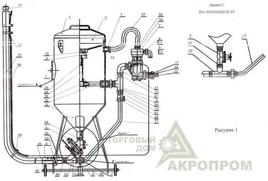
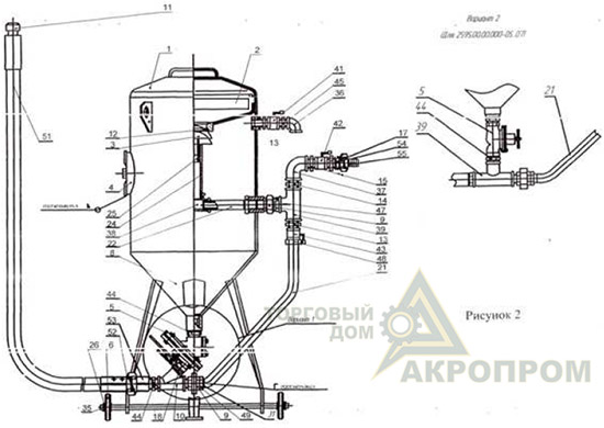
1. Крышка
2. Сито
3. Конус клапана
4. Люк
5. Затвор песчаный
6. Колесо
7. Клапан КПДУ
8. Корпус
9. Соединение
10. Соединение 135o
11. Сопло
12. Кольцо
13. Переход G1 (G1 .)
14. Переход G1 (G1 .)
15. Клавиша КПДУ
16. Переход G1 (G1 .)
17. Переход
18. Сгон
21. Труба
22. Труба
23. Труба
24. Труба
25. Труба
26. Втулка
27. Штуцер
28. Гайка
29. Гайка
30. Кольца
31. Соединение
35. Винт М6 ГОСТ 1476-75
36. Угольник 20 ГОСТ 8946-75
37. Угольник 25 (32) ГОСТ 8946-75
38. Угольник 25 (32) ГОСТ 8946-75
39. Угольник 25 (32) ГОСТ 8946-75
41. Кран 20
42. Кран 25 (32)
43. Кран 25 (32)
44. Ниппель 25 (32) ГОСТ 8958-75
45. Ниппель 25 (32) ГОСТ 8958-75
47. Контргайка 25 (32) ГОСТ 8968-75
48. Контргайка 25 (32) ГОСТ 8968-75
51. Рукав напорный Ш10-25 (32) ГОСТ 2405-79
52. Соединение струйное
53. Соединение струйное
54. Соединение воздушное 25 (32)
55. Соединение воздушное 25 (32)
56. Рукав управления клавишей КПДУ
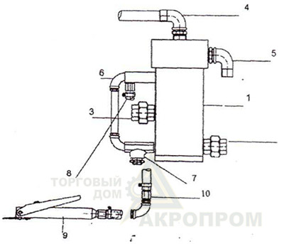
1 – конус клапана
2 – соединение разъемное (вход)
3 – соединение разъемное (выход)
4 – магистраль сброса давления
5 – угольник
6 – пневмомагистраль первичной и вторичной камеры
7 – вентиль регулировки включения клапана
8 – магистраль управления
9 – клавиша ДУ
10 – соединение разъемное