- Manuals
- Brands
- Yamaha Manuals
- Motorcycle
- FZ1
- Owner’s manual
-
Contents
-
Table of Contents
-
Troubleshooting
-
Bookmarks
Quick Links
OWNER’S MANUAL
FZS1000S
FZS1000SC
LIT-11626-17-40
5LV-28199-13
Related Manuals for Yamaha FZ1
Summary of Contents for Yamaha FZ1
-
Page 1
OWNER’S MANUAL FZS1000S FZS1000SC LIT-11626-17-40 5LV-28199-13… -
Page 2
EAU10041… -
Page 3
Congratulations on your purchase of the Yamaha FZS1000/FZS1000C. This model is the result of Yamaha’s vast experience in the production of fine sporting, touring, and pacesetting racing machines. It represents the high degree of craftsmanship and reliability that have made Yamaha a leader in these fields. -
Page 4: Important Manual Information
This manual should be considered a permanent part of this motorcycle and should remain with it even if the motorcycle is subsequently sold. Yamaha continually seeks advancements in product design and quality. Therefore, while this manual contains the most current product information available at the time of printing, there may be minor discrepancies between your motorcycle and this manual.
-
Page 5
IMPORTANT MANUAL INFORMATION EAU10192 AFFIX DEALER LABEL HERE FZS1000S/FZS1000SC OWNER’S MANUAL ©2003 by Yamaha Motor Corporation, U.S.A. 1st edition, June 2003 All rights reserved. Any reprinting or unauthorized use without the written permission of Yamaha Motor Corporation, U.S.A. is expressly prohibited. -
Page 6: Table Of Contents
TABLE OF CONTENTS SAFETY INFORMATION ….1-1 Sidestand ……..3-15 Adjusting the throttle cable Location of important labels ….1-5 Ignition circuit cut-off system ..3-16 free play ……..6-19 Adjusting the valve clearance ..6-20 DESCRIPTION ……..2-1 PRE-OPERATION CHECKS ….. 4-1 Tires ……….
-
Page 7
STORAGE ……….7-1 Care ……….7-1 Storage ………..7-3 SPECIFICATIONS ……8-1 CONSUMER INFORMATION…..9-1 Identification numbers ….9-1 Reporting safety defects ….9-3 Motorcycle noise regulation ….9-4 Maintenance record ……9-5 YAMAHA MOTOR CORPORATION, U.S.A. STREET AND ENDURO MOTORCYCLE LIMITED WARRANTY …….9-7 YAMAHA EXTENDED SERVICE (Y.E.S.) ……..9-9… -
Page 8: Safety Information
SAFETY INFORMATION EAU10270 AND/OR WHEN MADE NECES- • Ride where other motorists can SARY BY MECHANICAL CONDI- see you. Avoid riding in another MOTORCYCLES SINGLE TIONS. motorist’s blind spot. TRACK VEHICLES. THEIR SAFE USE Many accidents involve inexperi- AND OPERATION ARE DEPENDENT Safe riding enced operators.
-
Page 9
Modifications made to this motorcycle other motorists can see you. the single most critical factor in the pre- not approved by Yamaha, or the re- The posture of the operator and vention or reduction of head injuries. moval of original equipment, may ren- passenger is important for proper Always wear an approved helmet. -
Page 10
Since Yamaha cannot should be kept to a minimum. 188 kg (415 lb) (CAL) test all other accessories that may be •… -
Page 11
SAFETY INFORMATION Gasoline and exhaust gas • Do not park the motorcycle on a GASOLINE IS HIGHLY FLAMMA- slope or soft ground, otherwise it BLE: may fall over. • Always turn the engine off when • Do not park the motorcycle near refueling. -
Page 12: Location Of Important Labels
SAFETY INFORMATION EAU10381 Location of important labels Please read the following important labels carefully before operating this vehicle.
-
Page 13
SAFETY INFORMATION California only CAUTION Cleaning with alkaline or acid cleaner, gasoline or solvent will damage windshield. Use neutral detergent. 5JW-00 (5JW-2835Y-00) -
Page 14: Description
DESCRIPTION EAU10410 Left view 1. Front fork compression damping force adjusting screw (page 3-11) 9. Shock absorber assembly compression damping force adjusting screw (page 3-13) 2. Front fork rebound damping force adjusting screw (page 3-11) 10.Shock absorber assembly spring preload adjusting ring (page 3-13) 3.
-
Page 15: Right View
DESCRIPTION EAU10420 Right view 1. Owner’s tool kit (page 6-1) 9. Coolant reservoir (page 6-14) 2. Rear brake fluid reservoir (page 6-26) 3. Battery (page 6-33) 4. Front brake fluid reservoir (page 6-26) 5. Radiator cap (page 6-14) 6. Engine oil filter cartridge (page 6-12) 7.
-
Page 16: Controls And Instruments
DESCRIPTION EAU10430 Controls and instruments 1. Clutch lever (page 3-6) 9. Brake lever (page 3-7) 2. Left handlebar switches (page 3-5) 10.Throttle grip (page 6-19) 3. Starter (choke) lever (page 3-9) 4. Speedometer unit (page 3-3) 5. Main switch/steering lock (page 3-1) 6.
-
Page 17: Instrument And Control Functions
INSTRUMENT AND CONTROL FUNCTIONS EAU10460 EAU10680 To unlock the steering Main switch/steering lock LOCK The steering is locked, and all electrical systems are off. The key can be re- moved. To lock the steering 1. Push. 2. Turn. The main switch/steering lock controls the ignition and lighting systems, and is Push the key in, and then turn it to used to lock the steering.
-
Page 18: Indicator And Warning Lights
“ON”. 1. Left turn signal indicator light “ ” Yamaha dealer check the electrical cir- 2. Neutral indicator light “ ” If the warning light does not come on cuit.
-
Page 19: Speedometer Unit
INSTRUMENT AND CONTROL FUNCTIONS ECA10020 EAU11810 be traveled on a full tank of fuel. This in- Speedometer unit CAUTION: formation will enable you to plan future fuel stops. Do not operate the engine if it is overheated. To set a mode Push the “SELECT”…
-
Page 20: Tachometer Unit
INSTRUMENT AND CONTROL FUNCTIONS EAU11890 To set the clock EAU12100 Tachometer unit Self-diagnosis devices 1. Push both the “SELECT” and “RE- This model is equipped with a self-diag- SET” buttons for at least two sec- nosis device for the following electrical onds.
-
Page 21: Fuel Gauge
If the tachometer displays such an error EAU12110 EAU12341 Fuel gauge Handlebar switches code, note the circuit-specific number of r/min, and then have a Yamaha deal- Left er check the vehicle. ECA10040 CAUTION: When the tachometer displays an er- ror code, the vehicle should be checked as soon as possible in or- der to avoid engine damage.
-
Page 22: Clutch Lever
INSTRUMENT AND CONTROL FUNCTIONS EAU12400 ECA10050 EAU12820 Dimmer switch “ ” Clutch lever CAUTION: Set this switch to “ ” for the high See page 5-1 for starting instruc- beam and to “ ” for the low beam. tions prior to starting the engine. EAU12460 Turn signal switch “…
-
Page 23: Shift Pedal
INSTRUMENT AND CONTROL FUNCTIONS EAU12870 EAU12930 EAU12941 Shift pedal Brake lever Brake pedal The brake lever is located at the right handlebar grip. To apply the front brake, pull the lever toward the handle- bar grip. 1. Shift pedal 1. Brake pedal The shift pedal is located on the left The brake pedal is on the right side of side of the engine and is used in com-…
-
Page 24: Fuel Tank Cap
INSTRUMENT AND CONTROL FUNCTIONS EAU13070 EAU13210 Fuel tank cap NOTE: Fuel The fuel tank cap cannot be closed un- less the key is in the lock. In addition, the key cannot be removed if the cap is not properly closed and locked. EWA11090 WARNING Make sure that the fuel tank cap is…
-
Page 25: Starter (Choke) Lever
1. Starter (choke) lever “ ” Fuel tank capacity: mended by Yamaha because it can 21.0 L (5.55 US gal) (4.62 Imp.gal) Starting a cold engine requires a richer cause damage to the fuel system or ve-…
-
Page 26: Seat
INSTRUMENT AND CONTROL FUNCTIONS EAU13940 EAU14290 Seat Helmet holder To remove the seat 1. Insert the key into the seat lock, and then turn it clockwise. 1. Projection 2. Seat holder 1. Helmet holder 2. Push the rear of the seat down to 2.
-
Page 27: Storage Compartment
INSTRUMENT AND CONTROL FUNCTIONS EAU14450 When washing the vehicle, be careful EAU14750 Storage compartment Adjusting the front fork not to let any water enter the storage This front fork is equipped with spring compartment. preload adjusting bolts, rebound damp- ing force adjusting screws and com- pression damping force…
-
Page 28
INSTRUMENT AND CONTROL FUNCTIONS load thereby soften Rebound damping force Compression damping force suspension, turn the adjusting bolt on each fork leg in direction (b). NOTE: Align the appropriate groove on the ad- justing mechanism with the top of the front fork cap bolt. -
Page 29: Adjusting The Shock Absorber Assembly
INSTRUMENT AND CONTROL FUNCTIONS ECA10100 EAU15041 To increase the spring preload and Adjusting the shock absorber CAUTION: thereby harden the suspension, turn assembly the adjusting ring in direction (a). To de- Never attempt to turn an adjusting This shock absorber assembly is crease the spring preload and thereby mechanism beyond the maximum or equipped with a spring preload adjust-…
-
Page 30
INSTRUMENT AND CONTROL FUNCTIONS Rebound damping force Compression damping force NOTE: Although the total number of clicks of a damping force adjusting mechanism may not exactly match the above spec- ifications due to small differences in production, the actual number of clicks always represents the entire adjusting range. -
Page 31: Exup System
EAU15300 EXUP system Sidestand sorber to an open flame or other This model is equipped with Yamaha’s The sidestand is located on the left side high heat sources, otherwise it EXUP (EXhaust Ultimate Power valve) of the frame. Raise the sidestand or may explode due to excessive system.
-
Page 32: Ignition Circuit Cut-Off System
INSTRUMENT AND CONTROL FUNCTIONS below and have a Yamaha dealer re- EAU15321 Ignition circuit cut-off system pair it if it does not function proper- The ignition circuit cut-off system (com- prising the sidestand switch, clutch switch and neutral switch) has the fol- lowing functions.
-
Page 33
5. Push the start switch. Does the engine start? The neutral switch may be defective. The motorcycle should not be ridden until checked by a Yamaha dealer. With the engine still running: 6. Move the sidestand up. 7. Keep the clutch lever pulled. -
Page 34: Pre-Operation Checks
PRE-OPERATION CHECKS EAU15591 The condition of a vehicle is the owner’s responsibility. Vital components can start to deteriorate quickly and unexpectedly, even if the vehicle remains unused (for example, as a result of exposure to the elements). Any damage, fluid leakage or loss of tire air pressure could have serious consequences.
-
Page 35: Pre-Operation Check List
• If necessary, add recommended coolant to specified level. 6-14 • Check cooling system for leakage. • Check operation. • If soft or spongy, have Yamaha dealer bleed hydraulic system. • Check brake pads for wear. Front brake • Replace if necessary.
-
Page 36
• Make sure that operation is smooth. • Check cable free play. Throttle grip 6-19, 6-30 • If necessary, have Yamaha dealer adjust cable free play and lubricate cable and grip housing. • Make sure that operation is smooth. Control cables 6-29 •… -
Page 37: Operation And Important Riding Points
Never start the engine or oper- EWA10290 Yamaha dealer check the electrical cir- WARNING ate it in a closed area for any cuit. length of time. Exhaust fumes Before…
-
Page 38
35 seconds with the starter does not go off after starting starting with sufficient fuel, (choke) turned on, then about 2.5 min- have a Yamaha dealer check the with sufficient engine oil, have a utes with the starter (choke) in the half- electrical circuit. -
Page 39: Starting A Warm Engine
OPERATION AND IMPORTANT RIDING POINTS EAU16640 EAU16671 ECA10260 Starting a warm engine Shifting CAUTION: Follow the same procedure as for start- Even with the transmission in ing a cold engine with the exception the neutral position, do not that the starter (choke) is not required coast for long periods of time when the engine is warm.
-
Page 40: Engine Break-In
OPERATION AND IMPORTANT RIDING POINTS 4. At the recommended shift points 3. Shift the transmission into the neu- EAU16841 Engine break-in shown in the following table, close tral position when the motorcycle There is never a more important period the throttle, and at the same time, is almost completely stopped.
-
Page 41: Parking
Do not park on a slope or on soft the tachometer red zone. ground, otherwise the vehicle If any engine trouble should oc- may overturn. cur during the engine break-in period, immediately have a Yamaha dealer check the vehi- cle.
-
Page 42: Periodic Maintenance And Minor Repair
TRAINED AND EQUIPPED TO PER- wrench may be necessary to perform FORM THESE PARTICULAR SER- certain maintenance work correctly. VICES. NOTE: If you do not have the tools or experi- ence required for a particular job, have a Yamaha dealer perform it for you.
-
Page 43
PERIODIC MAINTENANCE AND MINOR REPAIR EWA10340 WARNING Modifications approved Yamaha may cause loss of perfor- mance, excessive emissions, and render the vehicle unsafe for use. Consult a Yamaha dealer before at- tempting any changes. -
Page 44: Periodic Maintenance Chart For The Emission Control System
PERIODIC MAINTENANCE AND MINOR REPAIR EAU17600 Periodic maintenance chart for the emission control system INITIAL ODOMETER READINGS 600 mi 4000 mi 8000 mi 12000 mi 16000 mi 20000 mi ITEM ROUTINE (1000 km) (7000 km) (13000 km) (19000 km) (25000 km) (31000 km) 1 month 6 months…
-
Page 45
• Check the air cut-off valve, reed Air induction sys- √ √ √ √ √ 10 * valve, and hose for damage. • Replace any damaged parts. * Since these items require special tools, data and technical skills, have a Yamaha dealer perform the service. -
Page 46: General Maintenance And Lubrication Chart
PERIODIC MAINTENANCE AND MINOR REPAIR EAU32181 General maintenance and lubrication chart INITIAL ODOMETER READINGS 600 mi 4000 mi 8000 mi 12000 mi 16000 mi 20000 mi ITEM ROUTINE (1000 km) (7000 km) (13000 km) (19000 km) (25000 km) (31000 km) 1 month 6 months 12 months…
-
Page 47
PERIODIC MAINTENANCE AND MINOR REPAIR INITIAL ODOMETER READINGS 600 mi 4000 mi 8000 mi 12000 mi 16000 mi 20000 mi ITEM ROUTINE (1000 km) (7000 km) (13000 km) (19000 km) (25000 km) (31000 km) 1 month 6 months 12 months 18 months 24 months 30 months… -
Page 48
Throttle grip hous- √ √ √ √ √ 24 * if necessary. ing and cable • Lubricate the throttle grip housing and cable. * Since these items require special tools, data and technical skills, have a Yamaha dealer perform the service. -
Page 49
PERIODIC MAINTENANCE AND MINOR REPAIR NOTE: From 24000 mi (37000 km) or 36 months, repeat the maintenance intervals starting from 8000 mi (13000 km) or 12 months. EAU17630 NOTE: The air filter needs more frequent service if you are riding in unusually wet or dusty areas. Hydraulic brake service •… -
Page 50: Removing And Installing Panels
PERIODIC MAINTENANCE AND MINOR REPAIR EAU18770 The panels shown above need to be re- Removing and installing moved to perform some of the mainte- panels nance jobs described in this chapter. Refer to this section each time a panel needs to be removed and installed. EAU19292 Panels A and C To remove one of the panels…
-
Page 51: Checking The Spark Plugs
Do not attempt to diagnose such 1. Spark plug cap problems yourself. Instead, have a 2. Remove the spark plug as shown, Yamaha dealer check the vehicle. with the spark plug wrench includ- ed in the owner’s tool kit. 6-10…
-
Page 52: Canister (For California Only)
PERIODIC MAINTENANCE AND MINOR REPAIR 3. Check each spark plug for elec- 2. Clean the surface of the spark plug EAU19671 Canister (for California only) trode erosion and excessive car- gasket and its mating surface, and bon or other deposits, and replace then wipe off any grime from the it if necessary.
-
Page 53: Engine Oil And Oil Filter Cartridge
PERIODIC MAINTENANCE AND MINOR REPAIR EAU19890 2. Place an oil pan under the engine Engine oil and oil filter NOTE: to collect the used oil. The engine oil should be between the cartridge 3. Remove the engine oil filler cap minimum and maximum level marks.
-
Page 54
Make sure that the O-ring is properly 17 Nm (1.7 m·kgf, 12 ft·lbf) An oil filter wrench is available at a seated. Yamaha dealer. 7. Install the engine oil drain bolt, and 6. Install the new oil filter cartridge then tighten it to the specified 5. -
Page 55: Coolant
EAU20101 ECA11620 or remains on, immediately turn the To check the coolant level CAUTION: engine off and have a Yamaha dealer 1. Place the vehicle on the center- In order to prevent clutch slip- check the vehicle. stand. page (since the engine oil also 10.
-
Page 56
If water has been added to the page 6-9.) el A (See page 6-9.), remove the coolant, have a Yamaha dealer 3. Place a container under the engine reservoir cap, add coolant to the check the antifreeze content of to collect the used coolant. -
Page 57
If water has been added to the Recommended antifreeze: coolant, have a Yamaha dealer High-quality ethylene glycol anti- freeze containing corrosion inhibitors check the antifreeze content of for aluminum engines… -
Page 58: Cleaning The Air Filter Element
12. Start the engine, and then check 3-10.) the vehicle for coolant leakage. If 2. Remove the fuel tank bolts. coolant is leaking, have a Yamaha dealer check the cooling system. 13. Install the panels. 1. Rubber cover 2. Rubber cover holder 1.
-
Page 59
Before installing the fuel tank, make sure that the fuel hoses are not damaged. If any fuel hose is damaged, do not start the engine but have a Yamaha dealer replace the hose, other- 1. Air filter case cover wise fuel may leak. -
Page 60: Adjusting The Carburetors
Therefore, all carburetor adjustments should be left to a Yamaha dealer, who has the necessary profes- sional knowledge and experience. 1. Throttle cable free play The throttle cable free play should mea- sure 3.0–5.0 mm (0.12–0.20 in) at the…
-
Page 61: Adjusting The Valve Clearance
Rear: from occurring, the valve clearance regarding the specified tires. 270 kPa (39 psi) (2.70 kgf/cm²) must be adjusted by a Yamaha dealer 90–188 kg (198–415 lb) (CAL) at the intervals specified in the periodic Tire air pressure 90–189 kg (198–417 lb) (U49): maintenance and lubrication chart.
-
Page 62
(minimum tread depth), if the tire has a nail or glass fragments in it, or if the sidewall is cracked, con- tact a Yamaha dealer immediately and have the tire replaced. Minimum tire tread depth (front and rear): 1.0 mm (0.04 in) -
Page 63
Tire air valve: tires listed below have been ap- TR412 proved this model Valve core: Yamaha Motor Co., Ltd. #9000A (original) Always make sure that the valve EWA10600 caps are securely installed to WARNING prevent air pressure leakage. This motorcycle is fitted with super- Use only the tire valves and high-speed tires. -
Page 64: Cast Wheels
The accessories or replace- fore each ride. If any damage is ment parts you choose for your found, have a Yamaha dealer re- motorcycle should be designed spe- place the wheel. Do not attempt cifically for this model, and they…
-
Page 65: Adjusting The Clutch Lever Free Play
Yamaha dealer check the internal clutch mechanism. 1. Clutch lever free play adjusting bolt 1. Distance between brake pedal and footrest 2. Clutch lever free play…
-
Page 66: Adjusting The Rear Brake Light Switch
PERIODIC MAINTENANCE AND MINOR REPAIR the braking performance, which may EAU22270 EAU22321 Adjusting the rear brake light Checking the front and rear result in loss of control and an acci- switch brake pads dent. Front brake 1. Rear brake light switch 2.
-
Page 67: Checking The Brake Fluid Level
When checking the fluid level, point that the wear indicator groove has make sure that the top of the brake almost disappeared, have a Yamaha fluid reservoir is level. dealer replace the brake pads as a set. Use only the recommended quality 1.
-
Page 68: Changing The Brake Fluid
EAU22760 Changing the brake fluid Drive chain slack ter the brake fluid reservoir when Have a Yamaha dealer change the The drive chain slack should be refilling. Water will significantly brake fluid at the intervals specified in checked before each ride and adjusted…
-
Page 69
PERIODIC MAINTENANCE AND MINOR REPAIR 3. Tighten the locknuts, and then NOTE: tighten the axle nut to the specified Using the alignment marks on each torque. side of the swingarm, make sure that both chain pullers are in the same posi- Tightening torque: tion for proper wheel alignment. -
Page 70: Lubricating The Drive Chain
Service the drive chain as ed if necessary. If a cable is damaged follows. or does not move smoothly, have a ECA10580 Yamaha dealer check or replace it. CAUTION: The drive chain must be lubricated Recommended lubricant: Yamaha Chain and Cable Lube or…
-
Page 71: Checking And Lubricating The Throttle Grip And Cable
PERIODIC MAINTENANCE AND MINOR REPAIR EAU23110 EAU23131 EAU23140 Checking and lubricating the Checking and lubricating the Checking and lubricating the throttle grip and cable brake and shift pedals brake and clutch levers The operation of the throttle grip should be checked before each ride. In addi- tion, the cable should be lubricated or replaced at the intervals specified in the periodic maintenance chart.
-
Page 72: Checking And Lubricating The Centerstand And Sidestand
If the centerstand or sidestand does push down hard on the handlebars not move up and down smoothly, several times to check if the front have a Yamaha dealer check or re- fork compresses and rebounds pair it. smoothly. Recommended lubricant:…
-
Page 73: Checking The Steering
Securely support the vehicle so that fork does not operate smoothly, there is no danger of it falling over. have a Yamaha dealer check or re- pair it. 2. Hold the lower ends of the front fork legs and try to move them for- ward and backward.
-
Page 74: Checking The Wheel Bearings
WARNING Electrolyte is poisonous and To charge the battery dangerous since it contains sul- Have a Yamaha dealer charge the bat- furic acid, which causes severe tery as soon as possible if it seems to burns. Avoid any contact with have discharged.
-
Page 75: Replacing The Fuses
(See sealed-type (MF) battery charg- check if the device operates. page 3-10.) er, have a Yamaha dealer 4. If the fuse immediately blows If a fuse is blown, replace it as follows. charge your battery.
-
Page 76: Replacing A Headlight Bulb
PERIODIC MAINTENANCE AND MINOR REPAIR EAU23730 Headlight bulb Replacing a headlight bulb Do not touch the glass part of This model is equipped with two quartz the headlight bulb to keep it free bulb headlights. If a headlight bulb from oil, otherwise the transpar- burns out, replace it as follows.
-
Page 77: Replacing A Tail/Brake Light Bulb
Replacing a tail/brake light and then connect the coupler. bulb 6. Install the panel. 1. Remove the seat. (See page 7. Have a Yamaha dealer adjust the 3-10.) headlight beam if necessary. 2. Remove the tail/brake light bulb cover. 1. Tail/brake light bulb socket 4.
-
Page 78: Replacing A Turn Signal Light Bulb
To remove the front wheel by removing the screw. EWA10820 WARNING It is advisable to have a Yamaha dealer service the wheel. Securely support the motor- cycle so that there is no danger of it falling over.
-
Page 79: Rear Wheel
2. Insert the wheel axle. EWA10820 3. Lower the front wheel so that it is WARNING on the ground. It is advisable to have a Yamaha 4. Install the brake calipers by install- dealer service the wheel. ing the bolts. Securely support the motor-…
-
Page 80
PERIODIC MAINTENANCE AND MINOR REPAIR 3. Disconnect the brake torque rod 6. Turn the drive chain slack adjust- EAU25841 To install the rear wheel from the brake caliper by removing ing bolts fully in direction (a). 1. Place the wheel and the brake cal- the nut and the bolt. -
Page 81: Troubleshooting
However, should your motorcycle require any repair, take it to a Yamaha Tightening torques: dealer, whose skilled technicians have Axle nut: 150 Nm (15.0 m·kgf, 108 ft·lbf)
-
Page 82: Troubleshooting Charts
Remove the spark plugs and check the electrodes. The engine does not start. Have a Yamaha dealer check the vehicle. Check the battery. 4. Battery The engine turns over The battery is good.
-
Page 83
Start the engine. If the engine overheats again, have a The coolant level Yamaha dealer check and repair the cooling system. is OK. NOTE: If coolant is not available, tap water can be temporarily used instead, provided that it is changed to the recommended coolant as soon as possible. -
Page 84: Motorcycle Care And Storage
MOTORCYCLE CARE AND STORAGE EAU26010 ucts onto seals, gaskets, sprock- cleaning products, solvent or Care ets, the drive chain and wheel thinner, fuel (gasoline), rust re- While the open design of a motorcycle axles. Always rinse the dirt and de- movers or inhibitors, brake flu- reveals the attractiveness of the tech- greaser off with water.
-
Page 85
MOTORCYCLE CARE AND STORAGE After normal use ECA10790 5. Use spray oil as a universal clean- CAUTION: Remove dirt with warm water, a mild er to remove any remaining dirt. detergent, and a soft, clean sponge, 6. Touch up minor paint damage Do not use warm water since it in- and then rinse thoroughly with clean caused by stones, etc. -
Page 86: Storage
CAUTION: NOTE: fuel from deteriorating. Storing the motorcycle in a Consult a Yamaha dealer for advice on 5. Perform the following steps to pro- poorly ventilated room or cover- what products to use. tect the cylinders, piston rings, etc.
-
Page 87
MOTORCYCLE CARE AND STORAGE EWA10950 °C (90 °F)]. For more information WARNING on storing the battery, see page To prevent damage or injury from 6-33. sparking, make sure to ground the NOTE: spark plug electrodes while turning Make any necessary repairs before the engine over. -
Page 88: Specifications
SPECIFICATIONS Dimensions: Engine oil: Carburetor: Overall length: Type: Manufacturer: 2125 mm (83.7 in) YAMALUBE 4, SAE10W30 or SAE20W40 MIKUNI Overall width: Type x quantity: 0° 10° 30° 50° 70° 90° 110° 130°F 765 mm (30.1 in) BSR37 x 4 YAMALUBE 4 (10W30) Overall height: Spark plug(s): or SAE 10W30…
-
Page 89
SPECIFICATIONS 3rd: (Total weight of rider, passenger, cargo and Front brake: 30/20 (1.500) accessories) Type: 4th: Tire air pressure (measured on cold Dual disc brake 28/21 (1.333) tires): Operation: 5th: Right hand operation Loading condition: 30/25 (1.200) Recommended fluid: 0–90 kg (0–198 lb) 6th: Dot 4 Front:… -
Page 90
SPECIFICATIONS Battery: Headlight fuse: 20.0 A Model: Signaling system fuse: GT14B-4 20.0 A Voltage, capacity: Ignition fuse: 12 V, 12.0 Ah 20.0 A Headlight: Radiator fan fuse: Bulb type: 10.0 A Halogen bulb Backup fuse: Bulb voltage, wattage x quantity: 10.0 A Headlight: 12 V, 60 W/55.0 W ×… -
Page 91: Consumer Information
Record the key identification number, vehicle identification number and mod- el label information in the spaces pro- vided below for assistance when ordering spare parts from a Yamaha dealer or for reference in case the vehi- cle is stolen. KEY IDENTIFICATION NUMBER: 1.
-
Page 92
1. Model label The model label is affixed to the frame under the seat. (See page 3-10.) Record the information on this label in the space provided. This information will be needed when ordering spare parts from a Yamaha dealer. -
Page 93: Reporting Safety Defects
If you believe that your vehicle has a defect which could cause a crash or could cause injury or death, you should immediately inform the National Highway Traffic Safety Administration (NHTSA) in addition to notifying Yamaha Motor Corporation, U.S.A. If NHTSA receives similar complaints, it may open an investigation, and if it finds that a safety defect exists in a group of vehicles, it may order a recall and remedy campaign.
-
Page 94: Motorcycle Noise Regulation
CONSUMER INFORMATION EAU26560 Motorcycle noise regulation TAMPERING WITH NOISE CONTROL SYSTEM PROHIBITED: Federal law prohibits the following acts or the causing thereof: (1) The removal or rendering inoperative by any person other than for purposes of maintenance, repair, or replacement of any device or element of design incorporated into any new ve- hicle for the purpose of noise control prior to its sale or delivery to the ultimate purchaser or while it is in use or (2) the use of the vehicle after such device or element of design has been removed or rendered inoperative by any person.
-
Page 95: Maintenance Record
CONSUMER INFORMATION EAU26631 Maintenance record Copies of work orders and/or receipts for parts purchased and installed on your motorcycle will be required to document that maintenance has been completed in accordance with the emissions warranty. The chart below is printed only as a reminder that maintenance work is required.
-
Page 96
CONSUMER INFORMATION Maintenance Date of Servicing dealer Mileage Remarks interval service name and address 36000 mi (55000 km) or 54 months 40000 mi (61000 km) or 60 months… -
Page 97: Yamaha Motor Corporation, U.s.a. Street And Enduro Motorcycle Limited Warranty
CONSUMER INFORMATION EAU26661 YAMAHA MOTOR CORPORATION, U.S.A. STREET AND ENDURO MOTORCYCLE LIMITED WARRANTY…
-
Page 98
CONSUMER INFORMATION… -
Page 99: Yamaha Extended Service (Y.e.s.)
This excellent Y.E.S. plan coverage is only available to dealer to see how comforting uninterrupted factory- Yamaha owners like you, and only while your Yamaha is still backed protection can be. within the Yamaha Limited Warranty period. So visit your authorized Yamaha dealer to get all the facts.
-
Page 100
Yamaha Limited Warranty expires. A special note: If visiting your dealer isn’t convenient, contact Yamaha with your Primary ID number (your frame number). We’ll be happy to help you get the Y.E.S. coverage you need. -
Page 101
INDEX EXUP system ……..3-15 Accessories and replacement parts ..6-23 Neutral indicator light ……3-2 Air filter element, cleaning ….6-17 Front and rear brake pads, Noise regulation……..9-4 checking……….6-25 Front fork, adjusting ……3-11 Battery ……….6-33 Oil level warning light ……3-2 Front fork, checking…….6-31 Brake and clutch levers, checking Fuel …………3-8… -
Page 102
INDEX Tachometer unit ……..3-4 Tail/brake light bulb, replacing ….6-36 Throttle cable free play, adjusting ..6-19 Throttle grip and cable, checking and lubricating ……..6-30 Tires …………6-20 Tool kit ………… 6-1 Troubleshooting ……..6-40 Troubleshooting charts ……6-41 Turn signal indicator lights …… -
Page 104
YAMAHA MOTOR CO., LTD. PRINTED ON RECYCLED PAPER PRINTED IN JAPAN 2003.06-0.8×1 CR…

Руководство по эксплуатации и техническому обслуживанию мотоциклов Yamaha моделей FZ1-N и FZ1-NA.
- Издательство: Yamaha Motor Co., Ltd.
- Год издания: 2010
- Страниц: 104
- Формат: PDF
- Размер: 3,7 Mb

Руководство по эксплуатации и техническому обслуживанию мотоциклов Yamaha моделей FZ1-S и FZ1-SA.
- Издательство: Yamaha Motor Co., Ltd.
- Год издания: 2010
- Страниц: 106
- Формат: PDF
- Размер: 4,3 Mb

Руководство по эксплуатации и техническому обслуживанию мотоциклов Yamaha FZ6-S Fazer.
- Издательство: Yamaha Motor Co., Ltd.
- Год издания: 2002
- Страниц: 104
- Формат: PDF
- Размер: 2,8 Mb

Руководство по эксплуатации и техническому обслуживанию мотоциклов Yamaha моделей FZ8-S и FZ8-SA Fazer.
- Издательство: Yamaha Motor Co., Ltd.
- Год издания: 2010
- Страниц: 101
- Формат: PDF
- Размер: 4,1 Mb

Руководство по эксплуатации и техническому обслуживанию мотоциклов Yamaha FZ8-N.
- Издательство: Yamaha Motor Co., Ltd.
- Год издания: 2010
- Страниц: 97
- Формат: PDF
- Размер: 3,7 Mb

Сборник руководств на английском языке по эксплуатации и техническому обслуживанию мотоциклов Yamaha моделей FZ1-N, FZ1-NA, FZ1-S и FZ1-SA Fazer.
- Издательство: Yamaha Motor Co., Ltd.
- Год издания: 2005-2011
- Страниц: —
- Формат: PDF
- Размер: 27,6 Mb

Сборник руководств на английском языке по эксплуатации и техническому обслуживанию мотоциклов Yamaha FZ6 Fazer различных моделей.
- Издательство: Yamaha Motor Co., Ltd.
- Год издания: 2003-2011
- Страниц: —
- Формат: PDF
- Размер: 46,7 Mb

Сборник руководств на английском языке по эксплуатации и техническому обслуживанию мотоциклов Yamaha моделей FZ8-N, FZ8-NA, FZ8-NAC, FZ8-S, FZ8-SA Fazer.
- Издательство: Yamaha Motor Co., Ltd.
- Год издания: 2010-2012
- Страниц: —
- Формат: PDF
- Размер: 13,0 Mb
Руководство на английском языке по техническому обслуживанию и ремонту мотоциклов Yamaha моделей FJ600, FZ600, XJ600 и YX600 Radian.
- Издательство: Haynes Publishing
- Год издания: —
- Страниц: 200
- Формат: PDF
- Размер: 89,6 Mb
Сборник руководств на английском языке по ремонту мотоциклов Yamaha моделей FZ1-N, FZ1-NA, FZ1-NV, FZ1-NX, FZ1-S, FZ1-SA, FZ1-SV, FZ1-SX Fazer 2006-2008 годов выпуска.
- Издательство: Yamaha Motor Co., Ltd.
- Год издания: 2005/2008
- Страниц: 451/546
- Формат: PDF
- Размер: 45,5 Mb
Руководство на английском языке по ремонту мотоциклов Yamaha моделей FZ6RY и FZ6RYC 2009 года выпуска.
- Издательство: Yamaha Motor Co., Ltd.
- Год издания: 2008
- Страниц: 420
- Формат: PDF
- Размер: 19,4 Mb
Руководство на английском языке по ремонту мотоциклов Yamaha моделей FZ6-SS и FZ6-SSC.
- Издательство: Yamaha Motor Co., Ltd.
- Год издания: 2003
- Страниц: 432
- Формат: PDF
- Размер: 13,1 Mb

Сборник руководств на английском, французском, немецком, испанском и итальянском языках по ремонту мотоциклов Yamaha моделей FZ-6N, FZ-6S и др.
- Издательство: Yamaha
- Год издания: —
- Страниц: —
- Формат: ISO
- Размер: 1,7 Gb
Руководство на немецком языке по техническому обслуживанию и ремонту мотоциклов Yamaha FZ750 с 1984 года выпуска.
- Издательство: —
- Год издания: —
- Страниц: 98
- Формат: PDF
- Размер: 4,4 Mb


OWNER’S MANUAL
FZS1000R
FZS1000RC
FZS1000SR
FZS1000SRC
|
LIT-11626-16-33 |
5LV-28199-12 |
EAU03438

Congratulations on your purchase of the Yamaha FZS1000/FZS1000S. This model is the result of Yamaha’s vast experience in the production of fine sporting, touring, and pacesetting racing machines. It represents the high degree of craftsmanship and reliability that have made Yamaha a leader in these fields.
This manual will give you an understanding of the operation, inspection, and basic maintenance of this motorcycle. If you have any questions concerning the operation or maintenance of your motorcycle, please consult a Yamaha dealer.
The design and manufacture of this Yamaha motorcycle fully comply with the emissions standards for clean air applicable at the date of manufacture. Yamaha has met these standards without reducing the performance or economy of operation of the motorcycle. To maintain these high standards, it is important that you and your Yamaha dealer pay close attention to the recommended maintenance schedules and operating instructions contained within this manual.
|
IMPORTANT MANUAL INFORMATION |
EAU00003 |
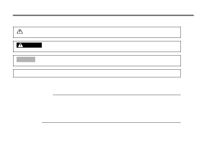
Particularly important information is distinguished in this manual by the following notations:
The Safety Alert Symbol means ATTENTION! BECOME ALERT! YOUR SAFETY IS
INVOLVED!
|
WARNING |
Failure to follow WARNING instructions could result in severe injury or death to the |
|
|
motorcycle operator, a bystander or a person inspecting or repairing the motorcycle. |
||
|
CAUTION: |
A CAUTION indicates special precautions that must be taken to avoid damage to the |
|
|
motorcycle. |
||
NOTE: A NOTE provides key information to make procedures easier or clearer.
NOTE:
●This manual should be considered a permanent part of this motorcycle and should remain with it even if the motorcycle is subsequently sold.
●Yamaha continually seeks advancements in product design and quality. Therefore, while this manual contains the most current product information available at the time of printing, there may be minor discrepancies between your motorcycle and this manual. If you have any questions concerning this manual, please consult your Yamaha dealer.
IMPORTANT MANUAL INFORMATION
EW000000
 WARNING
PLEASE READ THIS MANUAL AND THE “YOU AND YOUR MOTORCYCLE: RIDING TIPS” BOOKLET CAREFULLY AND COMPLETELY BEFORE OPERATING THIS MOTORCYCLE. DO NOT ATTEMPT TO OPERATE THIS MOTORCYCLE UNTIL YOU HAVE ATTAINED ADEQUATE KNOWLEDGE OF ITS CONTROLS AND OPERATING FEATURES AND UNTIL YOU HAVE BEEN TRAINED IN SAFE AND PROPER RIDING TECHNIQUES. REGULAR INSPECTIONS AND CAREFUL MAINTENANCE, ALONG WITH GOOD RIDING SKILLS, WILL ENSURE THAT YOU SAFELY ENJOY THE CAPABILITIES AND THE RELIABILITY OF THIS MOTORCYCLE.
IMPORTANT MANUAL INFORMATION
AFFIX DEALER
LABEL HERE
EAU04247
FZS1000R/FZS1000RC/FZS1000SR/FZS1000SRC
OWNER’S MANUAL
©2002 by Yamaha Motor Corporation, U.S.A. 1st edition, May 2002
All rights reserved.
Any reprinting or unauthorized use without the written permission of Yamaha Motor Corporation, U.S.A. is expressly prohibited.
Printed in Japan.
P/N LIT-11626-16-33

|
EAU00009 |
TABLE OF CONTENTS |
|
1 |
SAFETY INFORMATION |
1 |
|
|
2 |
DESCRIPTION |
2 |
|
|
3 |
INSTRUMENT AND CONTROL FUNCTIONS |
3 |
|
|
4 |
PRE-OPERATION CHECKS |
4 |
|
|
5 |
OPERATION AND IMPORTANT RIDING POINTS |
5 |
|
|
6 |
PERIODIC MAINTENANCE AND MINOR REPAIR |
6 |
|
|
7 |
MOTORCYCLE CARE AND STORAGE |
7 |
|
|
8 |
SPECIFICATIONS |
8 |
|
|
9 |
CONSUMER INFORMATION |
9 |
|
INDEX

SAFETY INFORMATION |
|||||
|
Safe riding ……………………………………………………………………………… |
1-1 |
||||
|
Protective apparel |
1-3 |
||||
|
1 |
|||||
|
Modifications |
|||||
|
1-3 |
|||||
|
………………………………………………………….Loading and accessories |
1-3 |
||||
|
Gasoline and exhaust gas………………………………………………………… |
1-5 |
||||
|
Location of important labels …………………………………………………….. |
1-7 |
||||
|
SAFETY INFORMATION |
EAU00014 |
MOTORCYCLES ARE SINGLE TRACK VEHICLES. THEIR SAFE USE AND OPERATION ARE DEPENDENT UPON THE USE OF PROPER RIDING TECHNIQUES AS WELL AS THE EXPERTISE OF THE OPERATOR. EVERY OPERATOR SHOULD KNOW THE FOLLOWING REQUIREMENTS
1 BEFORE RIDING THIS MOTORCYCLE. HE OR SHE SHOULD:
1.OBTAIN THOROUGH INSTRUCTIONS FROM A COMPETENT SOURCE ON ALL ASPECTS OF MOTORCYCLE OPERATION.
2.OBSERVE THE WARNINGS AND MAINTENANCE REQUIREMENTS IN THE OWNER’S MANUAL.
3.OBTAIN QUALIFIED TRAINING IN SAFE AND PROPER RIDING TECHNIQUES.
4.OBTAIN PROFESSIONAL TECHNICAL SERVICE AS INDICATED BY THE OWNER’S MANUAL AND/OR WHEN MADE NECESSARY BY MECHANICAL CONDITIONS.
Safe riding
1.Always make pre-operation checks. Careful checks may help prevent an accident.
2.This motorcycle is designed to carry the operator and a passenger.
3.The failure of motorists to detect and recognize motorcycles in traffic is the predominating cause of automobile/motorcycle accidents. Many accidents have been caused by an automobile driver who
did not see the motorcycle. Making yourself conspicuous appears to be very effective in reducing the chance of this type of accident.
Therefore:
a.Wear a brightly colored jacket.
b.Use extra caution when you are approaching and passing through intersections, since intersections are the most likely places for motorcycle accidents to occur.
c.Ride where other motorists can see you. Avoid riding in another motorist’s blind spot.
1-1


 SAFETY INFORMATION
4.Many accidents involve inexperienced operators. In fact, many operators who have been involved in accidents do not even have a current motorcycle license.
a.Make sure that you are qualified and that you only lend your motorcycle to other qualified operators.
b.Know your skills and limits. Staying within your limits may help you to avoid an accident.
c.We recommend that you practice riding your motorcycle where there is no traffic until you have become thoroughly familiar with the motorcycle and all of its controls.
5.Many accidents have been caused by error of the motorcycle operator. A typical error made by the operator is veering wide on a turn due to EXCESSIVE SPEED or undercornering (insufficient lean angle for the speed).
a.Always obey the speed limit and never travel faster than warranted by road and traffic conditions.
b.Always signal before turning or changing lanes. Make sure that other motorists can see you.
6.The posture of the operator and passenger is important for proper control.
a.The operator should keep both hands on the handlebar and both feet on the operator footrests
during operation to maintain control of the motorcycle.
b.The passenger should always hold onto the operator, the seat strap or grab bar, if equipped, with both hands and keep both feet on the passenger footrests.
c.Never carry a passenger unless he or she can firmly place both feet on the passenger footrests.
7.Never ride under the influence of alcohol or other drugs.
8.This motorcycle is designed for on-road use only. It is not suitable for off-road use.
1-2
![]()

 SAFETY INFORMATION
Protective apparel
|
The majority of fatalities from motorcycle accidents are the result of head injuries. The use of a safety |
|||
|
1 |
helmet is the single most critical factor in the prevention or reduction of head injuries. |
||
|
1. |
Always wear an approved helmet. |
||
|
2. |
Wear a face shield or goggles. Wind in your unprotected eyes could contribute to an impairment of vi- |
||
|
sion that could delay seeing a hazard. |
|||
|
3. |
The use of a jacket, heavy boots, trousers, gloves, etc., is effective in preventing or reducing abra- |
||
|
sions or lacerations. |
|||
|
4. |
Never wear loose-fitting clothes, otherwise they could catch on the control levers, footrests, or wheels |
||
|
and cause injury or an accident. |
|||
|
5. |
Never touch the engine or exhaust system during or after operation. They become very hot and can |
||
|
cause burns. Always wear protective clothing that covers your legs, ankles, and feet. |
|||
|
6. |
A passenger should also observe the above precautions. |
Modifications
Modifications made to this motorcycle not approved by Yamaha, or the removal of original equipment, may render the motorcycle unsafe for use and may cause severe personal injury. Modifications may also make your motorcycle illegal to use.
Loading and accessories
Adding accessories or cargo to your motorcycle can adversely affect stability and handling if the weight distribution of the motorcycle is changed. To avoid the possibility of an accident, use extreme caution when adding cargo or accessories to your motorcycle. Use extra care when riding a motorcycle that has added cargo or accessories. Here are some general guidelines to follow if loading cargo or adding accessories to your motorcycle:
1-3


 SAFETY INFORMATION
Loading
The total weight of the operator, passenger, accessories and cargo must not exceed the maximum load limit of FZS1000, FZS1000S: 189 kg (417 lb) / FZS1000C, FZS1000SC: 188 kg (415 lb). When loading within this weight limit, keep the following in mind:
1.Cargo and accessory weight should be kept as low and close to the motorcycle as possible. Make sure to distribute the weight as evenly as possible on both sides of the motorcycle to minimize imbalance or instability.
2.Shifting weights can create a sudden imbalance. Make sure that accessories and cargo are securely attached to the motorcycle before riding. Check accessory mounts and cargo restraints frequently.
3.Never attach any large or heavy items to the handlebar, front fork, or front fender. These items, including such items as sleeping bags, duffel bags, or tents, can create unstable handling or a slow steering response.
Accessories
Genuine Yamaha accessories have been specifically designed for use on this motorcycle. Since Yamaha cannot test all other accessories that may be available, you must personally be responsible for the proper selection, installation and use of non-Yamaha accessories. Use extreme caution when selecting and installing any accessories.
Keep the following guidelines in mind, as well as those provided under “Loading” when mounting accessories.
1.Never install accessories or carry cargo that would impair the performance of your motorcycle. Carefully inspect the accessory before using it to make sure that it does not in any way reduce ground clearance or cornering clearance, limit suspension travel, steering travel or control operation, or obscure lights or reflectors.
1-4


 SAFETY INFORMATION
a.Accessories fitted to the handlebar or the front fork area can create instability due to improper weight distribution or aerodynamic changes. If accessories are added to the handlebar or front
fork area, they must be as lightweight as possible and should be kept to a minimum.
1 b. Bulky or large accessories may seriously affect the stability of the motorcycle due to aerodynamic effects. Wind may attempt to lift the motorcycle, or the motorcycle may become unstable in cross winds. These accessories may also cause instability when passing or being passed by large vehicles.
c.Certain accessories can displace the operator from his or her normal riding position. This improper position limits the freedom of movement of the operator and may limit control ability, therefore, such accessories are not recommended.
2.Use caution when adding electrical accessories. If electrical accessories exceed the capacity of the motorcycle’s electrical system, an electric failure could result, which could cause a dangerous loss of lights or engine power.
Gasoline and exhaust gas
1.GASOLINE IS HIGHLY FLAMMABLE:
a.Always turn the engine off when refueling.
b.Take care not to spill any gasoline on the engine or exhaust system when refueling.
c.Never refuel while smoking or in the vicinity of an open flame.
2.Never start the engine or let it run for any length of time in a closed area. The exhaust fumes are poisonous and may cause loss of consciousness and death within a short time. Always operate your motorcycle in an area that has adequate ventilation.
3.Always turn the engine off before leaving the motorcycle unattended and remove the key from the main switch. When parking the motorcycle, note the following:
1-5

 SAFETY INFORMATION
a.The engine and exhaust system may be hot, therefore, park the motorcycle in a place where pedestrians or children are not likely to touch these hot areas.
b.Do not park the motorcycle on a slope or soft ground, otherwise it may fall over.
c. Do not park the motorcycle near a flammable source (e.g., a kerosene heater, or near an open 1 flame), otherwise it could catch fire.
4.When transporting the motorcycle in another vehicle, make sure that it is kept upright. If the motorcycle should lean over, gasoline may leak out of the carburetor or fuel tank.
5.If you should swallow any gasoline, inhale a lot of gasoline vapor, or allow gasoline to get into your eyes, see your doctor immediately. If any gasoline spills on your skin or clothing, immediately wash the affected area with soap and water and change your clothes.
6
1-6


 SAFETY INFORMATION
EAU02977
Location of important labels
Please read the following important labels carefully before operating this motorcycle.
1
1-7

|
SAFETY INFORMATION |
||
|
1 |
5 California only |
|
|
CAUTION |
||
|
Cleaning with alkaline or |
1 |
|
|
acid cleaner, gasoline or |
solvent will damage windshield.
Use neutral detergent.
5JW-00 (5JW-2835Y-00)
2
6
1-8

DESCRIPTION |
|
|
Left view ………………………………………………………………………………… |
2-1 |
|
Right view………………………………………………………………………………. |
2-2 |
|
Controls and instruments …………………………………………………………. |
2-3 |
2

Left view
2
|
1. Front fork compression damping |
8. Seat lock/helmet holder |
(page 3-11) |
|
|
force adjusting screw |
(page 3-14) |
9. Shock absorber assembly |
|
|
2. Front fork rebound damping force |
compression damping force |
||
|
adjusting screw |
(page 3-13) |
adjusting screw |
(page 3-16) |
|
3. Front fork spring preload adjusting |
10. Shock absorber assembly spring |
||
|
bolt |
(page 3-13) |
preload adjusting ring |
(page 3-15) |
|
4. Air filter element |
(page 6-19) |
11. Shock absorber assembly rebound |
|
|
5. Fuses |
(page 6-38) |
damping force adjusting knob |
(page 3-15) |
|
6. Storage compartment |
(page 3-12) |
12. Shift pedal |
(page 3-7) |
|
7. Grab bar |
2-1

DESCRIPTION
Right view
2
|
13. Owner’s tool kit |
(page 6-1) |
18. Engine oil filter cartridge |
(page 6-13) |
|
14. Rear brake fluid reservoir |
(page 6-30) |
19. Engine oil level check window |
(page 6-12) |
|
15. Battery |
(page 6-37) |
20. Brake pedal |
(page 3-8) |
|
16. Front brake fluid reservoir |
(page 6-29) |
21. Coolant reservoir |
(page 6-15) |
|
17. Radiator cap |
(page 6-17) |
2-2
DESCRIPTION
Controls and instruments
2
|
1. Clutch lever |
(page 3-7) |
6. Tachometer unit |
(page 3-4) |
|
2. Left handlebar switches |
(page 3-6) |
7. Fuel gauge |
(page 3-5) |
|
3. Starter (choke) lever |
(page 3-10) |
8. Right handlebar switches |
(page 3-6) |
|
4. Speedometer unit |
(page 3-3) |
9. Brake lever |
(page 3-7) |
|
5. Main switch/steering lock |
(page 3-1) |
10. Throttle grip |
(page 6-22) |
2-3
![]()
INSTRUMENT AND CONTROL FUNCTIONS
|
…………………………………………………………Main switch/steering lock |
3-1 |
|||
|
Indicator and warning lights ……………………………………………………. |
3-2 |
|||
|
Speedometer unit …………………………………………………………………… |
3-3 |
|||
|
Tachometer unit ……………………………………………………………………… |
3-4 |
|||
|
Self-diagnosis devices …………………………………………………………….. |
3-5 |
|||
|
Fuel gauge |
3-5 |
|||
|
3 |
||||
|
Handlebar switches |
3-6 |
|||
|
……………………………………………………………………………Clutch lever |
3-7 |
|||
|
Shift pedal …………………………………………………………………………….. |
3-7 |
|||
|
Brake lever ……………………………………………………………………………. |
3-7 |
|||
|
Brake pedal …………………………………………………………………………… |
3-8 |
|||
|
Fuel tank cap …………………………………………………………………………. |
3-8 |
|||
|
Fuel ……………………………………………………………………………………… |
3-9 |
|||
|
Starter (choke) lever ……………………………………………………………… |
3-10 |
|||
|
Seat ……………………………………………………………………………………. |
3-11 |
|||
|
Helmet holder ………………………………………………………………………. |
3-11 |
|||
|
Storage compartment …………………………………………………………… |
3-12 |
|||
|
Adjusting the front fork ………………………………………………………….. |
3-12 |
|||
|
Adjusting the shock absorber assembly …………………………………… |
3-14 |
|||
|
EXUP system ………………………………………………………………………. |
3-17 |
|||
|
Sidestand ……………………………………………………………………………. |
3-17 |
|||
|
Ignition circuit cut-off system ………………………………………………….. |
3-18 |
|||
|
INSTRUMENT AND CONTROL FUNCTIONS |
EAU00027 |
3
1. Push.
2. Turn.
Main switch/steering lock
The main switch/steering lock controls the ignition and lighting systems, and is used to lock the steering. The various positions are described below.
EAU00032
ON
All electrical systems are supplied with power, and the headlight, meter lighting, taillight and position lights come on, and the engine can be started. The key cannot be removed.
EAU00038
OFF
All electrical systems are off. The key can be removed.
LOCK
The steering is locked, and all electrical systems are off. The key can be removed.
To lock the steering
1.Turn the handlebars all the way to the left.
2.Push the key in from the “OFF” position, and then turn it to “LOCK” while still pushing it.
3.Remove the key.
To unlock the steering
Push the key in, and then turn it to “OFF” while still pushing it.
EW000016
 WARNING
_
Never turn the key to “OFF” or “LOCK” while the motorcycle is moving, otherwise the electrical systems will be switched off, which may result in loss of control or an accident. Make sure that the motorcycle is stopped before turning the key to “OFF” or “LOCK”.
_
3-1
INSTRUMENT AND CONTROL FUNCTIONS
1.Left turn signal indicator light “  ”
”
2.Neutral indicator light “  ”
”
3.High beam indicator light “ ”
”
4.Oil level warning light “ 

 ”
”
5.Right turn signal indicator light “  ”
”
6.Coolant temperature warning light “  ”
”
7.Fuel level warning light “  ”
”
EAU03034
Indicator and warning lights
EAU04121
Turn signal indicator lights
“  ” and “
 ”
”
The corresponding indicator light flashes when the turn signal switch is pushed to the left or right.
EAU00063
High beam indicator light “ ”
”
This indicator light comes on when the high beam of the headlight is switched on.
EAU04877
Oil level warning light “ 

 ”
”
This warning light comes on when the engine oil level is low.
The electrical circuit of the warning light can be checked by turning the key to “ON”.
If the warning light does not come on for a few seconds, then go off, have a Yamaha dealer check the electrical circuit.
NOTE:
Even if the oil level is sufficient, the warning light may flicker when riding on a slope or during sudden acceleration or deceleration, but this is not a malfunction.
EAU04881
Coolant temperature warning light
“  ”
”
This warning light comes on when the engine overheats. When this occurs, stop the engine immediately and allow the engine to cool.
The electrical circuit of the warning light
can be checked by turning the key to 3 “ON”.
If the warning light does not come on for a few seconds, then go off, have a Yamaha dealer check the electrical circuit.
EC000002
CAUTION:
_
Do not operate the engine if it is overheated.
_
EAU00061
Neutral indicator light “  ”
”
This indicator light comes on when the transmission is in the neutral position.
3-2
INSTRUMENT AND CONTROL FUNCTIONS
3
1.Left turn signal indicator light “  ”
”
2.Neutral indicator light “  ”
”
3.High beam indicator light “ ”
”
4.Oil level warning light “ 

 ”
”
5.Right turn signal indicator light “  ”
”
6.Coolant temperature warning light “  ”
”
7.Fuel level warning light “  ”
”
EAU04878
Fuel level warning light “  ”
”
This warning light comes on when the fuel level drops below approximately 4 L (0.9 Imp gal, 1.1 US gal). When this occurs, refuel as soon as possible.
The electrical circuit of the warning light can be checked by turning the key to “ON”.
If the warning light does not come on for a few seconds, then go off, have a Yamaha dealer check the electrical circuit.
1.Speedometer
2.Odometer/tripmeter
3.“SELECT” button
4.“RESET” button
EAU04289
Speedometer unit
The speedometer unit is equipped with the following:
●an odometer
●two tripmeters
When set to “ODO”, the motorcycle’s total mileage is indicated.
When set to “TRIP 1” or “TRIP 2”, the motorcycle’s mileage since the tripmeter was last reset is indicated. The tripmeters can be used together with the fuel gauge to estimate the distance that can be traveled on a full tank of fuel.
This information will enable you to plan future fuel stops.
To set a mode
Push the “SELECT” button to change between the odometer mode “ODO”, and the tripmeter modes “TRIP 1” and “TRIP 2” in the following order:
ODO → TRIP 1 → TRIP 2 → ODO
To reset a meter
To reset either tripmeter 1 or 2 to 0.0, select either by pushing the “SELECT” button, and then push the “RESET” button for at least one second.
3-3
INSTRUMENT AND CONTROL FUNCTIONS
1.Tachometer
2.Tachometer red zone
3.Clock
EAU03954
Tachometer unit
The electric tachometer allows the rider to monitor the engine speed and keep it within the ideal power range.
EC000003
CAUTION:
Do not operate the engine in the tachometer red zone.
Red zone: 11,500 r/min and above
This tachometer unit is equipped with a clock.
To set the clock:
1.Push both the “SELECT” and “RESET” buttons for at least two seconds.
2.When the hour digits start flashing,
push the “RESET” button to set the hours.
3. Push the “SELECT” button to 3 change the minutes.
4.When the minute digits start flashing, push the “RESET” button to set the minutes.
5.Push the “SELECT” button to start the clock.
NOTE:
After setting the clock, be sure to push the “SELECT” button before turning the key to “OFF”, otherwise the clock will not be set.
3-4
INSTRUMENT AND CONTROL FUNCTIONS
EAU04290
Self-diagnosis devices
This model is equipped with a self-di- agnosis device for the following electrical circuits:
● throttle position sensor ● speed sensor
3
● EXUP system ● overturn switch
If any of those circuits are defective, the tachometer will repeatedly display the following error code:
|
0 r/min for |
Circuit-specific |
Current |
|
|
number of r/min |
engine |
||
|
3 seconds |
|||
|
for 2.5 seconds |
speed for |
||
|
(See the table |
3 seconds |
||
|
below.) |
Use the chart below to identify the faulty electrical circuit.
|
Specific r/min |
Faulty electrical circuit |
|
3,000 r/min |
Throttle position sensor |
|
4,000 r/min |
Speed sensor |
|
7,000 r/min |
EXUP system |
|
9,000 r/min |
Overturn switch |
If the tachometer displays such an error code, note the circuit-specific number of r/min, and then have a Yamaha dealer check the motorcycle.
EC000004
CAUTION:
When the tachometer displays an error code, the motorcycle should be checked as soon as possible in order to avoid engine damage.
1. Fuel gauge
EAU00110
Fuel gauge
The fuel gauge indicates the amount of fuel in the fuel tank. The needle moves towards “E” (Empty) as the fuel level decreases. When the needle reaches “E”, approximately 4 L (0.9 Imp gal, 1.1 US gal) of fuel remain in the fuel tank. If this occurs, refuel as soon as possible.
NOTE:
_
Do not allow the fuel tank to empty itself completely.
_
3-5

INSTRUMENT AND CONTROL FUNCTIONS
1.Dimmer switch “ /
/  ”
”
2.Turn signal switch “  /
/  ”
”
3.Horn switch “  ”
”
EAU00118
Handlebar switches
EAU03888
Dimmer switch “ /
/  ”
”
Set this switch to “ ” for the high beam and to “
  ” for the low beam.
EAU03889
Turn signal switch “  /
/  ”
”
To signal a right-hand turn, push this switch to “  ”. To signal a left-hand turn, push this switch to “
  ”. When released, the switch returns to the center position. To cancel the turn signal lights, push the switch in after it has returned to the center position.
EAU00129
Horn switch “  ”
”
Press this switch to sound the horn.
3
1.Engine stop switch “  /
/  ”
”
2.Start switch “  ”
”
EAU03890
Engine stop switch “  /
/  ”
”
Set this switch to “  ” before starting the engine. Set this switch to “
  ” to stop the engine in case of an emergency, such as when the motorcycle overturns or when the throttle cable is stuck.
EAU00143
Start switch “  ”
”
Push this switch to crank the engine with the starter.
EC000005
CAUTION:
_
See page 5-1 for starting instructions prior to starting the engine.
_
3-6
INSTRUMENT AND CONTROL FUNCTIONS
3
1. Clutch lever
EAU00152
Clutch lever
The clutch lever is located at the left handlebar grip. To disengage the clutch, pull the lever toward the handlebar grip. To engage the clutch, release the lever. The lever should be pulled rapidly and released slowly for smooth clutch operation.
The clutch lever is equipped with a clutch switch, which is part of the ignition circuit cut-off system. (See page 3-18 for an explanation of the ignition circuit cut-off system.)
1. Shift pedal
EAU00157
Shift pedal
The shift pedal is located on the left side of the engine and is used in combination with the clutch lever when shifting the gears of the 6-speed con- stant-mesh transmission equipped on this motorcycle.
1.Brake lever
2.Brake lever position adjusting dial
3.Arrow mark
a.Distance between brake lever and handlebar grip
EAU00161
Brake lever
The brake lever is located at the right handlebar grip. To apply the front brake, pull the lever toward the handlebar grip. The brake lever is equipped with a position adjusting dial. To adjust the distance between the brake lever and the handlebar grip, turn the adjusting dial while holding the lever pushed away from the handlebar grip. Make sure that the appropriate setting on the adjusting dial is aligned with the arrow mark on the brake lever.
3-7
INSTRUMENT AND CONTROL FUNCTIONS
1. Brake pedal
EAU00162
Brake pedal
The brake pedal is on the right side of the motorcycle. To apply the rear brake, press down on the brake pedal.
1.Fuel tank cap lock cover
2.Unlock.
EAU02935
Fuel tank cap
To open the fuel tank cap
Open the fuel tank cap lock cover, insert the key into the lock, and then turn it 1/4 turn clockwise. The lock will be released and the fuel tank cap can be opened.
2.Turn the key counterclockwise to the original position, remove it, and then close the lock cover.
NOTE:
_
The fuel tank cap cannot be closed unless the key is in the lock. In addition, the key cannot be removed if the cap is
|
not properly closed and locked. |
3 |
|||
|
_ |
||||
|
EWA00025 |
||||
|
WARNING |
||||
|
_ |
Make sure that the fuel tank cap is properly closed before riding.
_
To close the fuel tank cap
1.Push the fuel tank cap into position with the key inserted in the lock.
3-8

INSTRUMENT AND CONTROL FUNCTIONS
EAU00185
CAUTION:
Immediately wipe off spilled fuel with a clean, dry, soft cloth, since fuel may deteriorate painted surfaces or plastic parts.
3
1.Fuel tank filler tube
2.Fuel level
EAU03753
Fuel
Make sure that there is sufficient fuel in the tank. Fill the fuel tank to the bottom of the filler tube as shown.
EW000130
 WARNING
●Do not overfill the fuel tank, otherwise it may overflow when the fuel warms up and expands.
●Avoid spilling fuel on the hot engine.
EAU04265
Recommended fuel:
UNLEADED GASOLINE ONLY Fuel tank capacity:
Total amount:
21 L (4.6 Imp gal, 5.5 US gal) Reserve amount:
4 L (0.9 Imp gal, 1.1 US gal)
ECA00104
CAUTION:
_
Use only unleaded gasoline. The use of leaded gasoline will cause severe damage to internal engine parts, such as the valves and piston rings, as well as to the exhaust system.
_
3-9
![]()
INSTRUMENT AND CONTROL FUNCTIONS
|
Your Yamaha engine has been de- |
|||||
|
signed to use regular unleaded gaso- |
|||||
|
line with a pump octane number |
|||||
|
[(R+M)/2] of 86 or higher, or a research |
|||||
|
octane number of 91 or higher. If |
|||||
|
knocking (or pinging) occurs, use a |
|||||
|
gasoline of a different brand or premi- |
|||||
|
um unleaded fuel. Use of unleaded fuel |
3 |
||||
|
will extend spark plug life and reduce |
|||||
|
1. Starter (choke) lever “ |
” |
||||
|
maintenance costs. |
|||||
|
EAU03839 |
|||||
Gasohol
There are two types of gasohol: gasohol containing ethanol and that containing methanol. Gasohol containing ethanol can be used if the ethanol content does not exceed 10%. Gasohol containing methanol is not recommended by Yamaha because it can cause damage to the fuel system or vehicle performance problems.
Starter (choke) lever “ 

 ”
”
Starting a cold engine requires a richer air-fuel mixture, which is supplied by the starter (choke).
Move the lever in direction a to turn on the starter (choke).
Move the lever in direction b to turn off the starter (choke).
3-10

INSTRUMENT AND CONTROL FUNCTIONS
3
1.Seat lock
2.Unlock.
EAU03956
Seat
To remove the seat
1.Insert the key into the seat lock, and then turn it clockwise.
2.While holding the key in that position, lift the rear of the seat, and then pull the seat off.
1.Projection
2.Seat holder
To install the seat
1.Insert the projection on the front of the seat into the seat holder as shown.
2.Push the rear of the seat down to lock it in place.
3.Remove the key.
NOTE:
Make sure that the seat is properly secured before riding.
1.Helmet holder
2.Unlock.
EAU04291
Helmet holder
To open the helmet holder, insert the key into the seat lock, and then turn the key as shown.
To lock the helmet holder, turn the key to the original position, and then remove it.
EW000030
 WARNING
_
Never ride with a helmet attached to the helmet holder, since the helmet may hit objects, causing loss of control and possibly an accident.
_
3-11

INSTRUMENT AND CONTROL FUNCTIONS
When storing the owner’s manual or other documents in the storage compartment, be sure to wrap them in a plastic bag so that they will not get wet. When washing the motorcycle, be careful not to let any water enter the storage compartment.
1. Storage compartment
EAU04101
Storage compartment
The storage compartment is located under the seat. (See page 3-11 for seat removal and installation procedures.)
EWA00005
 WARNING
●Do not exceed the load limit of 3 kg (7 lb) for the storage compartment.
●Do not exceed the maximum load of FZS1000, FZS1000S: 189 kg (417 lb) / FZS1000C, FZS1000SC: 188 kg (415 lb) for the vehicle.
EAU04293
Adjusting the front fork
This front fork is equipped with spring preload adjusting bolts, rebound damping force adjusting screws and compression damping force adjusting screws.
|
EW000035 |
3 |
|||
|
WARNING |
||||
|
_ |
Always adjust both fork legs equally, otherwise poor handling and loss of stability may result.
_
3-12

INSTRUMENT AND CONTROL FUNCTIONS
3
1. Spring preload adjusting bolt
Spring preload
To increase the spring preload and thereby harden the suspension, turn the adjusting bolt on each fork leg in direction a. To decrease the spring preload and thereby soften the suspension, turn the adjusting bolt on each fork leg in direction b.
1.Current setting
2.Front fork cap bolt
NOTE:
Align the appropriate groove on the adjusting mechanism with the top of the front fork cap bolt.
|
Setting |
|
|
Minimum (soft) |
5* |
|
Standard |
2 |
|
Maximum (hard) |
1 |
* fully turned out position
1. Rebound damping force adjusting screw
Rebound damping force
To increase the rebound damping force and thereby harden the rebound damping, turn the adjusting screw on each fork leg in direction a. To decrease the rebound damping force and thereby soften the rebound damping, turn the adjusting screw on each fork leg in direction b.
|
Minimum (soft) |
17 clicks in direction b* |
|
Standard |
7 clicks in direction b* |
|
Maximum (hard) |
1 click in direction b* |
* With the adjusting screw fully turned in direction a
3-13

INSTRUMENT AND CONTROL FUNCTIONS
1. Compression damping force adjusting screw
Compression damping force
To increase the compression damping force and thereby harden the compression damping, turn the adjusting screw on each fork leg in direction a. To decrease the compression damping force and thereby soften the compression damping, turn the adjusting screw on each fork leg in direction b.
|
Minimum (soft) |
21 clicks in direction b* |
|
Standard |
6 clicks in direction b* |
|
Maximum (hard) |
1 click in direction b* |
* With the adjusting screw fully turned in direction a
EC000015
CAUTION:
Never attempt to turn an adjusting mechanism beyond the maximum or minimum settings.
NOTE:
Although the total number of clicks of a damping force adjusting mechanism may not exactly match the above specifications due to small differences in production, the actual number of clicks always represents the entire adjusting range. To obtain a precise adjustment, it would be advisable to check the number of clicks of each damping force adjusting mechanism and to modify the specifications as necessary.
|
EAU04295* |
||||
|
Adjusting the shock absorber |
||||
|
assembly |
||||
|
This shock absorber assembly is |
||||
|
equipped with a spring preload adjust- |
||||
|
ing ring, a rebound damping force ad- |
||||
|
justing knob and a compression |
||||
|
damping force adjusting screw. |
3 |
|||
|
EC000015 |
||||
|
CAUTION: |
||||
|
_ |
||||
|
Never attempt to turn an adjusting |
||||
|
mechanism beyond the maximum |
||||
|
or minimum settings. |
_
3-14

INSTRUMENT AND CONTROL FUNCTIONS
3
1.Spring preload adjusting ring
2.Special wrench
3.Position indicator
Spring preload
To increase the spring preload and thereby harden the suspension, turn the adjusting ring in direction a. To decrease the spring preload and thereby soften the suspension, turn the adjusting ring in direction b.
NOTE:
●Align the appropriate notch in the adjusting ring with the position indicator on the shock absorber.
●Use the special wrench included in the owner’s tool kit to make the adjustment.
|
Setting |
|
|
Minimum (soft) |
1 |
|
Standard |
6 |
|
Maximum (hard) |
11 |
1. Rebound damping force adjusting knob
Rebound damping force
To increase the rebound damping force and thereby harden the rebound damping, turn the adjusting knob in direction a. To decrease the rebound damping force and thereby soften the rebound damping, turn the adjusting knob in direction b.
|
Minimum (soft) |
20 clicks in direction b* |
|
Standard |
10 clicks in direction b* |
|
Maximum (hard) |
3 clicks in direction b* |
* With the adjusting knob fully turned in direction a
3-15

INSTRUMENT AND CONTROL FUNCTIONS
1. Compression damping force adjusting screw
Compression damping force
To increase the compression damping force and thereby harden the compression damping, turn the adjusting screw in direction a. To decrease the compression damping force and thereby soften the compression damping, turn the adjusting screw in direction b.
|
Minimum (soft) |
1 click in direction a* |
|
Standard |
7 clicks in direction a* |
|
Maximum (hard) |
12 clicks in direction a* |
* With the adjusting screw fully turned in direction b
NOTE:
Although the total number of clicks of a damping force adjusting mechanism may not exactly match the above specifications due to small differences in production, the actual number of clicks always represents the entire adjusting range. To obtain a precise adjustment, it would be advisable to check the number of clicks of each damping force adjusting mechanism and to modify the specifications as necessary.
EAU00315
WARNING
_
This shock absorber contains high-
|
ly pressurized nitrogen gas. For |
||
|
proper handling, read and under- |
||
|
stand the following information be- |
||
|
fore handling the shock absorber. |
||
|
The manufacturer cannot be held re- |
3 |
|
|
sponsible for property damage or |
||
|
personal injury that may result from |
||
|
improper handling. |
●Do not tamper with or attempt to open the gas cylinder.
●Do not subject the shock absorber to an open flame or other high heat sources, otherwise it may explode due to excessive gas pressure.
●Do not deform or damage the gas cylinder in any way, as this will result in poor damping performance.
●Always have a Yamaha dealer service the shock absorber.
_
3-16

INSTRUMENT AND CONTROL FUNCTIONS
EAU01571
EXUP system
This motorcycle is equipped with Yamaha’s EXUP (EXhaust Ultimate Power valve) system. This system boosts engine power by means of a valve that regulates the diameter of the
3
exhaust pipe. The EXUP system valve is constantly adjusted in accordance with the engine speed by a computercontrolled servomotor.
EC000027
CAUTION:
●The EXUP system has been set and extensively tested at the Yamaha factory. Changing these settings without sufficient technical knowledge may result in poor performance of or damage to the engine.
●If the EXUP system does not operate, have a Yamaha dealer check it.
EAU00330
Sidestand
The sidestand is located on the left side of the frame. Raise the sidestand or lower it with your foot while holding the motorcycle upright.
NOTE:
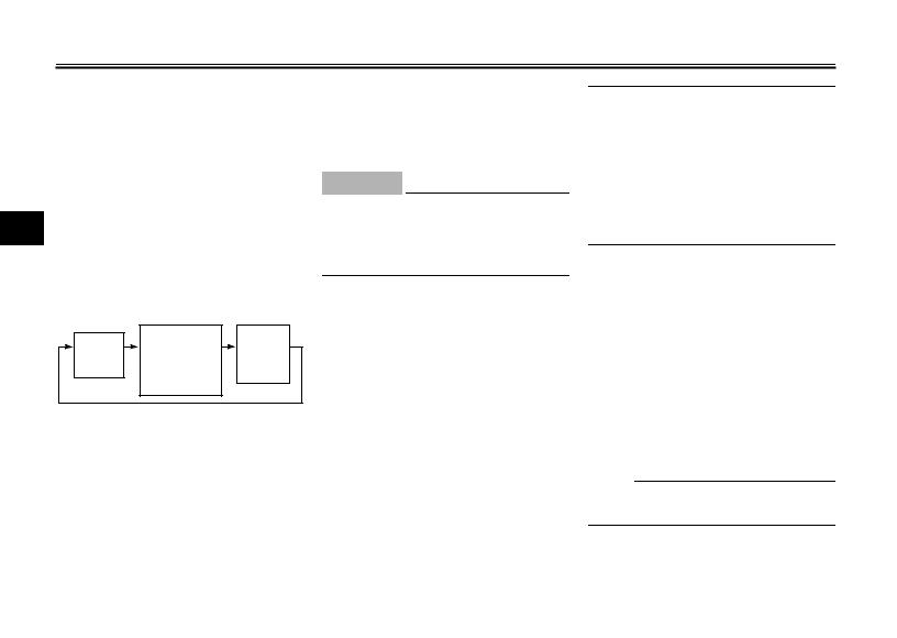
The built-in sidestand switch is part of the ignition circuit cut-off system, which cuts the ignition in certain situations. (See further down for an explanation of the ignition circuit cut-off system.)
EW000044
WARNING
_
The motorcycle must not be ridden with the sidestand down, or if the sidestand cannot be properly moved up (or does not stay up), otherwise the sidestand could contact the ground and distract the operator, resulting in a possible loss of control. Yamaha’s ignition circuit cut-off system has been designed to assist the operator in fulfilling the responsibility of raising the sidestand before starting off. Therefore, check this system regularly as described below and have a Yamaha dealer repair it if it does not function properly.
_
3-17
 Loading…