-
Contents
-
Table of Contents
-
Bookmarks
Quick Links
Related Manuals for Photron Fastcam SA6
Summary of Contents for Photron Fastcam SA6
-
Page 2
• This manual was created taking every possible measure to ensure the accuracy of its contents. However, if you find a section which is unclear, a mistake, or an omission, please contact Photron Limited using the contact information provided at the end of the manual. • Photron Limited bears no responsibility for the results of using the product or from following the instructions in this manual. ®… -
Page 3
This manual contains the operating instructions and warnings necessary for using the Photron FASTCAM Viewer (referred to as PFV). Please read the entire manual before using the software. If any part of this manual is unclear, contact Photron using the contact information printed at the back of this manual. -
Page 4
Manual Notation The following icons and symbols are used in the explanations in this manual. Icon/Symbol Description This symbol indicates content that should always be read. This symbol indicates instructions that should always be followed when using the software, or things to be careful of when using the software. -
Page 5: Table Of Contents
Table of Contents Chapter. 1 Before Use 1.1. Photron FASTCAM Viewer Overview …………..2 1.1.1. What Is PFV? ………………..2 1.1.2. System Components……………….2 1.1.3. What PFV Does ………………3 1.1.4. FASTCAM Series High-Speed Camera Capability Chart 1 ……4 1.1.5. FASTCAM Series High-Speed Camera Capability Chart 2 ……6 1.1.6.
-
Page 6
2.5.10. Select Playback Speed (Memory Mode Only) ……….43 2.5.11. Set Playback Start Frame (Memory Mode Only) ……..44 2.5.12. Set Current Frame (Memory Mode Only) ……….44 2.5.13. Set Playback End Frame (Memory Mode Only) ……..45 2.6. Crosshair Cursor………………..46 2.7. Drawing Text/Graphics……………….48 2.7.1. -
Page 7
3.11.1. For Start, Two-Stage, Random, And Random Reset Modes ….140 3.11.2. For Center, End, And Manual Modes…………142 3.11.3. Time-lapse Recording …………….144 3.11.4. Recording by the Image Trigger…………..150 Chapter. 4 Image Playback 4.1. Playing Images Recorded On the Camera …………160 4.2. Playback at the Selected Speed …………….164 4.3. -
Page 8
7.1.6. Shading Setting………………238 7.1.7. PFV Exit Setting ………………238 7.2. Settings Related To Saving Data ……………..239 7.2.1. Auto-Split AVI File Setting ……………239 7.2.2. AVI File Playback Speed Setting………….240 7.2.3. Save the Settings for the Live Mode Display Screen ……241 7.2.4. Specify and Save Partitions …………..242 7.2.5. -
Page 9
8.5. Video Border Data ………………..287 8.6. IRG File Structure ………………..289 8.7. MCD File Structure………………..290 8.8. WVD File Structure ………………..294 8.9. CSV File Structure ………………..296 8.9.1. TYPE A………………..296 8.9.2. TYPE B ………………..297 8.10. Settings Saved In the PCS File …………….298 Index Contacting Photron… -
Page 11: Chapter. 1 Before Use
The following describes what to do before using the PFV for the first time. <Chapter.1 Contents> What is PFV? An overview of the Setup control software. Connect the camera and PC, install PFV. FASTCAM Series High-Speed Camera Shooting Camera Control Recording Playback Saving Photron FASTCAM Viewer…
-
Page 12: Photron Fastcam Viewer Overview
Photron FASTCAM Viewer Overview 1.1.1. What Is PFV? PFV is software used to control Photron FASTCAM series high-speed cameras from the PC. Operations such as setting camera options, shooting, and saving recorded data to the PC can be accomplished with PFV.
-
Page 13: What Pfv Does
Save as a specified file type Save a specified area or number of frames Add information to an image and save Play saved data Play/resave data saved to the PC Chapter.6 page 219 Read/simultaneous playback of multiple data Photron FASTCAM Viewer…
-
Page 14: Fastcam Series High-Speed Camera Capability Chart 1
Chapter. 1 0BBefore Use 1.1.4. FASTCAM Series High-Speed Camera Capability Chart 1 Function / Model Name FASTCAM SA6 FASTCAM BC2 HD FASTCAM SA5 FASTCAM SA2 FASTCAM SA4 Variable Frame Rate / Resolution √ √ √ √ √ Auto Exposure √…
-
Page 15
√ √ √ √ √ √ √ √ √ √ √ √ √ √ √ √ √ √ √ √ √ √ √ √ √ √ √ √ √ √ √ √ √ √ √ √ √ Photron FASTCAM Viewer… -
Page 16: Fastcam Series High-Speed Camera Capability Chart 2
Chapter. 1 0BBefore Use 1.1.5. FASTCAM Series High-Speed Camera Capability Chart 2 Function / Model Name FASTCAM MC2 FASTCAM MC2.1 FASTCAM MC1 FASTCAM MH4 — 10K Variable Frame Rate / Resolution Auto Exposure Low-Light Mode √ √ √ √ Shading Correction Pixel Gain Correction Edge Enhancement Correction √…
-
Page 17
FASTCAM – APX FASTCAM — Ultima 512 √ √ √ √ √ √ √ √ √ √ √ √ √ √ √ √ √ √ √ √ √ √ √ √ √ √ √ √ √ √ Photron FASTCAM Viewer… -
Page 18: Fastcam Series High-Speed Camera Capability Chart 3
Chapter. 1 0BBefore Use 1.1.6. FASTCAM Series High-Speed Camera Capability Chart 3 Function / Model Name IDP-Express R2000 IDP-Express R2000-F FASTCAM — 1024PCI FASTCAM — 512PCI √ Variable Frame Rate / Resolution Auto Exposure Low-Light Mode √ √ √ Shading Correction √…
-
Page 19: Setup
1.2. Setup Installing the PFV Software. 1.2.1. Necessary Items Ready the PFV software installation CD. Photron cameras compatible with PFV Ver. 3 are listed below. Product Name Connection Method Compatible OS FASTCAM SA6 FASTCAM SA4 FASTCAM BC2 HD FASTCAM SA5…
-
Page 20: Verify The Operating Environment
・A CD-ROM drive (for use during installation) ・When using the Gigabit Ethernet connection, a 1000Base-T capable NIC Other with “Jumbo Frame” support is recommended ・When using the Photron Optical connection, a Photron Optical interface PCI board is necessary…
-
Page 21: Connecting The Camera And Pc
・Cable appropriate to the connection method Connection Method Cable Gigabit Ethernet LAN cable (category 5e or higher) PCI Express x8 IEEE1394 IEEE1394 cable Photron Optical Optical fiber cable • You must install the appropriate drivers for the connection method. Photron FASTCAM Viewer…
-
Page 22: Installing Pfv
Chapter. 1 0BBefore Use 1.2.4. Installing PFV Install PFV using the procedure shown below. Insert the PFV installation CD in the CD (or DVD) drive and open that drive form “Computer”. For a 32-bit version of Windows, open the «PFV Setup32» folder and double click «Setup.exe». For a 64-bit version of Windows, open the «PFV Setup64″…
-
Page 23
The license agreement is displayed. Confirm the contents and click the [Yes] button. Specify the installation location. The default setting for the installation location is “C:Program FilesPhotronPhotron FASTCAM Viewer 3”. When necessary, click the [Browse] button and change the installation location to your preferred location. -
Page 24: Installing Directx
Chapter. 1 0BBefore Use 1.2.5. Installing DirectX To read and write movie files in the AVI 2.0 format on an operating system other than Windows XP, Windows Vista or Windows 7, DirectX 8.1 or higher must be installed. Install DirectX with the procedure shown below. Insert the PFV installation CD into the CD or DVD drive and explore the CD from “My Computer”.
-
Page 25
When the installation is finished, the screen below is displayed. Click the [Finish] button and restart the computer. • Contact Microsoft Corporation regarding any problems that occur to the PC as a result of the DirectX installation. Photron FASTCAM Viewer… -
Page 26
Chapter. 1 0BBefore Use… -
Page 27: Chapter. 2 Basic Operation
The following describes the basic operation of the PFV. <Chapter.2 Contents> Running PFV An explanation of starting and closing the PFV control software, including an explanation of the screen names and functions experienced when running FASTCAM Series High-speed Camera Shooting Camera Control Recording Playback Saving Photron FASTCAM Viewer…
-
Page 28: Starting And Closing Pfv
Before starting PFV, verify that the camera is connected to the PC and that the power on the camera is turned on. 2.1.1. Starting PFV Click on [start] button — “All Programs” — “Photron FASTCAM Viewer 3” — “PFV Ver.3”. Or double-click on the desktop. PFV starts.
-
Page 29: Closing Pfv
The exit message is displayed. Do not turn off the camera’s power while this message is displayed. • For IDP-Express, the following message is displayed. After confirming the details of the message, click the [Yes] button to display the exit message and exit PFV. Photron FASTCAM Viewer…
-
Page 30: Screen Description
Chapter. 2 Basic Operation 2.2. Screen Description When PFV is started with the camera connected, the screen below is displayed. Verify the name of the parts. Menu Bar Contains the menus to start and stop PFV, display/hide the view windows, and the configuration settings. Toolbar Contains the functions related to the image displayed in the View Window.
-
Page 31
• Options to display/hide the control panel, playback control panel, toolbar, and plug-in bar are available on the [View] menu. To return to the normal display from the full-screen display, hold the “Alt” key and press the “Enter” key. Photron FASTCAM Viewer… -
Page 32: Displaying The Live Image
Chapter. 2 Basic Operation 2.3. Displaying the Live Image With PFV, the image being shot by the camera can be displayed as-is (displayed in live mode) on the PC screen when the camera is connected to the PC. Display the “Camera” tab on the control panel and select the camera to display the live image. Click the “Camera”…
-
Page 33
For how to verify the IP address, refer to “7.1.3. Set/Verify the Camera’s IP Address”, page 233. Check the camera lens aperture is open. Check the shutter speed or frame rate setting (see if the image will display when the speed is lowered). Photron FASTCAM Viewer… -
Page 34: When Multiple Cameras Are Connected
Chapter. 2 Basic Operation 2.3.1. When Multiple Cameras Are Connected When multiple cameras are connected, the “Camera” list will display “All Cameras”. A view window for each camera is displayed when “All Cameras” is selected. • The view window can be closed with the [X] button in the upper right hand corner of each window. The view window can be opened again with [File] menu –…
-
Page 35: When Connected To A Multi-Head Camera
(single head live image) display. When in single screen display (single head live image), by double clicking again, the display will switch back to the split screen display. Split Display Double-click on the desired camera head view Single Screen (Single Head) Display Photron FASTCAM Viewer…
-
Page 36: Zoom Window Display
Chapter. 2 Basic Operation 2.3.3. Zoom Window Display You can display the desired area enlarged in a separate window on the view window. Right click on the view window and click on the desired display scale factor under [View Window Display]. The zoom window is displayed.
-
Page 37: View Window Information
When the values are the default, nothing is displayed. The RGB plane info is displayed by the currently selected RGB plane. Changing Show/Hide The view window information can be shown or hidden by checking the “Show Info” option on each of the control panel tabs. Photron FASTCAM Viewer…
-
Page 38
Chapter. 2 Basic Operation Customize Display Information The displayed information can be customized. Click the [Edit Info] button located on each one of the control panel tabs. Select and check the information to display and click the [OK] button. • Time codes are only displayed during playback. They are not displayed in live mode. •… -
Page 39: Display Device Information
PFV to make the new setting effective. Click on [Help] menu – [Device Information]. The information for the devices connected is displayed. To change IP addresses, first click the device to be changed and then click the [Change IP address/ID] button. Photron FASTCAM Viewer…
-
Page 40
Chapter. 2 Basic Operation Enter a new IP address in the [New value] field and click the [Change] button. Click the [OK] button. Shut down and restart the PFV, and the new settings are reflected. • Changing the IP address is only possible when a connection between the PC and camera is established. -
Page 41: Toolbar
After clicking this button, dragging up on the view window will enlarge the display, dragging down will shrink the display. Zoom Area After clicking this button, drag the cursor to draw a rectangle over the portion of the view window to display, and the specified area will be enlarged. Photron FASTCAM Viewer…
-
Page 42
Chapter. 2 Basic Operation Button Button Name/Function Set Scaling Factor After clicking this button, select the optional scaling factor from the displayed list, and the display will be scaled by that factor. Same Pixel Size Display the image in the view window set to the same pixel size as that of the PC screen. -
Page 43
Double click on the view window to display cursor 2. Double click on the view window again and you can return the operational subject to cursor 1. Click the [Crosshair Cursor] button again to hide the cursor. For this procedure, refer to «2.6. Crosshair Cursor», page 47. Photron FASTCAM Viewer… -
Page 44
Chapter. 2 Basic Operation Button Button Name/Function Show/Hide the Drawing Toolbar Click this button to display the drawing toolbar. Click it again to hide the drawing toolbar. For the drawing toolbar function, refer to “2.7.1. Drawing Toolbar”, page 48. Scale Display Click this button to be able to configure settings related to the scale display. -
Page 45: Plug-In Bar
The plug-in for polarized light high speed camera control. For details, refer to the «Polarized Light Plug-in Manual». • For plug-in bar display settings, refer to “7.3.5. Setting Plug-in Bar”, page 255. • For details, refer to “2.10 Plug-in Bar Operations”, page 59. Photron FASTCAM Viewer…
-
Page 46: Waveform Input Board Bar
Chapter. 2 Basic Operation 2.4.3. Waveform Input Board Bar When the waveform input board is connected, the waveform input board bar is displayed and displays the state of the waveform input board. Button Button Name/Function Open Puts the waveform input board in a useable state. You can set various options on the screen displayed after clicking this button.
-
Page 47: Time-Lapse Bar
Displays the recording state with the image trigger. • For the image trigger, refer to «3.11.4. Recording by the Image Trigger», page 150. • For stopping playback by an image trigger, refer to «4.8. Stop Playback by Image Trigger», page 171. Photron FASTCAM Viewer…
-
Page 48: Navigation Mode
Chapter. 2 Basic Operation 2.5. Navigation Mode When the [Navigation Mode] button on the toolbar is clicked, the view window is divided into 9 regions and the navigation tool can be used. [Navigation Mode] button The divided regions contain functions such as zoom or pan/move. By using the navigation tool, each of the settings can be made on the view window without using the toolbar buttons.
-
Page 49: Gamma Correction
Drag the mouse to correct while checking the gamma value displayed in the guide in the lower right of the view window. Drag up/down 2.5.2. Adjust Contrast When the mouse cursor is in the upper center region of the view window, the cursor changes to Drag up/down Photron FASTCAM Viewer…
-
Page 50: Adjust Brightness
Chapter. 2 Basic Operation 2.5.3. Adjust Brightness When the mouse cursor is in the upper right region of the view window, the cursor changes to Drag the mouse to adjust while checking the brightness value displayed in the guide in the lower right of the view window.
-
Page 51: Pan/Move
When the mouse cursor is in the center right region of the view window, the cursor changes to Drag the mouse to set while checking the currently selected trigger mode displayed in the guide in the lower right of the view window. Drag up/down Photron FASTCAM Viewer…
-
Page 52: Select Frame Rate (Live Mode, Live Stop Mode)
Chapter. 2 Basic Operation 2.5.7. Select Frame Rate (Live Mode, Live Stop Mode) When the mouse cursor is in the lower left region of the view window, the cursor changes to Drag the mouse to set while checking the currently selected frame rate displayed in the guide in the lower right of the view window.
-
Page 53: Select Resolution (Live Mode, Live Stop Mode)
When the mouse cursor is in the center right region of the view window, the cursor changes to Drag the mouse to set while checking the currently selected playback speed displayed in the guide in the lower right of the view window. Drag up/down Photron FASTCAM Viewer…
-
Page 54: Set Playback Start Frame (Memory Mode Only)
Chapter. 2 Basic Operation 2.5.11. Set Playback Start Frame (Memory Mode Only) When the mouse cursor is in the lower left region of the view window, the cursor changes to Drag the mouse to set while checking the position of the playback start frame displayed in the guide at the bottom of the view window.
-
Page 55: Set Playback End Frame (Memory Mode Only)
When the mouse cursor is in the lower right region of the view window, the cursor changes to Drag the mouse to set while checking the position of the playback end frame displayed in the guide at the bottom of the view window. Drag left/right Photron FASTCAM Viewer…
-
Page 56: Crosshair Cursor
Chapter. 2 Basic Operation 2.6. Crosshair Cursor This function can display the crosshair cursor on the frame (on the view window). The coordinates and RGB value of the location pointed at are displayed in the view window information. Click the [Crosshair Cursor] button on the standard toolbar. Cursor 1 is displayed when you move the mouse pointer on the view window and the information is displayed in the view window information.
-
Page 57
To hide the displayed cursor, right click on the view window and remove the check next to the cursor under [Cross Cursor]. • You can show or hide the crosshair cursor by clicking on the [Crosshair Cursor] button on the standard toolbar. Photron FASTCAM Viewer… -
Page 58: Drawing Text/Graphics
Chapter. 2 Basic Operation 2.7. Drawing Text/Graphics This function draws text and graphics on the frame (on the view window). The graphics are only reflected in the frame that was drawn on, but with the [Overlay current drawing image to all] button, you can also reflect the graphics in all frames.
-
Page 59: Drawing On A Frame
Drawing on a Frame Click the [Show/Hide Drawing Toolbar] button on the standard toolbar to display the drawing toolbar. • When the drawing toolbar is displayed, only the [Pan or Move] button on the toolbar can be used. Photron FASTCAM Viewer…
-
Page 60
Chapter. 2 Basic Operation Click the button of the graphic to draw and draw by dragging the cursor at the desired location on the view window. The graphic is drawn. -
Page 61
When drawing a graphic to be filled with the desired color, click on the desired color with the [Color] button and after clicking the [OK] button, draw the graphic. After clicking the [Fill] button on the drawing toolbar, draw a graphic. Photron FASTCAM Viewer… -
Page 62
Chapter. 2 Basic Operation The graphic is drawn filled with the specified color. When drawing text, after clicking the [Text Box] button, click at the desired location on the frame (on the view window) and enter the text with the displayed dialog box. You can specify the text color, font, and size with the [Font] button. -
Page 63
• When you save monochrome images (frames shot in monochrome), the graphics are also saved as monochrome. • When reflecting the graphics drawn in all frames, after drawing the graphics, click the [Overlay current drawing image to all] button on the drawing toolbar. Photron FASTCAM Viewer… -
Page 64: Scale Display
Chapter. 2 Basic Operation 2.8. Scale Display The scale display shows a ruler or grid lines on the frame (view window). You can display a ruler or grid lines with a reference value of the desired length. The set value is reflected in the reference value for distance measurements.
-
Page 65
2 points». Click on any two points on the image (the start point and the end point) and after confirming the pixels, enter the desired value in «Corresponding distance». Enter the distance corresponding to between the 2 points Photron FASTCAM Viewer… -
Page 66
Chapter. 2 Basic Operation Click the «Edit Info» button on the control panel and check «Scale Calibration», «Scale Grid», «Scale Ruler» to display the measurement result, grid lines, and ruler on the view window. Grid lines Ruler ・1 grid width ・Displayed width ・Displayed height Settings on the scale display setup window… -
Page 67: Live Image And File Image Overlay Display
• For how to open files, refer to «6.1.1. Open Saved Data», page 220. After displaying the «Camera» tab, click the [Image Overlay] button on the standard toolbar. Select the image file to use as the background for the live image on the displayed list. Photron FASTCAM Viewer…
-
Page 68
Chapter. 2 Basic Operation The selected image is displayed as the background. In the view window, drag up to increase the transparency of the live image. Drag down to decrease its transparency. • The overlay display is only active in live mode. •… -
Page 69: Plug-In Bar Operations
The “Angle measurement” dialog box is displayed. To reflect the measurement results on all frames, check “Drawing objects are applied to all frames”. To change the color of the measurement result, click the color displayed to the right of “Line color” to change. Photron FASTCAM Viewer…
-
Page 70
Chapter. 2 Basic Operation Click on three points – start point (A), vertex of angle (O) and direction point (B) – to draw two lines forming an angle to be measured on the view window. The angle is measured and the result is displayed in the lower right corner. The angle is measured in the clockwise direction from the line between points O and A. -
Page 71: Distance Measurement Between Two Points
To reflect the measurement results on all frames, check “Drawing objects are applied to all frames”. To change the color of the measurement result, click the color displayed to the right of “Line color” to change. Click at a point within the view window, which is the start point of measurement. Photron FASTCAM Viewer…
-
Page 72
Chapter. 2 Basic Operation Click at another point within the view window, which is the end point of measurement. The distance between two points is calculated based on the scale setting and displayed in the lower right. The reference value is 1 mm/1 pixel (default value). To change this value, set it under the scale display. -
Page 73: Histogram Display
Shows a histogram (graph of brightness values) of the desired range on the view window. Click the [Histogram] button on the plug-in bar to activate the function. Specify the range to measure on the view window. Click the upper left which will be the starting point of the range. Photron FASTCAM Viewer…
-
Page 74
Chapter. 2 Basic Operation Click the lower right which will be the end point of the range. The histogram is displayed. -
Page 75
The target level position can be moved by dragging it below the graph’s horizontal axis. Drag right/left Target level position Information Shows the frequency information for the target level and the total frequency display area for the range displayed in the graph. Photron FASTCAM Viewer… -
Page 76
Chapter. 2 Basic Operation On the “Analyze” tab, you can check the maximum, minimum, and standard deviation values after conversion. To display in 256 levels, check “8 bits indication”. • On the «CSV» tab, you can output the histogram to a CSV file. (The histogram cannot be output in live mode.) After specifying the output range on the playback control panel, click the [Export data] button. -
Page 77: Rs-232C Control
RS-232C and the control settings. Click the [RS-232C Control] button on the plug-in bar to activate the function. The “PFV Communication tool” dialog box is displayed. Configure the connection settings with the connected device. Click the “Setting” button. Photron FASTCAM Viewer…
-
Page 78
Chapter. 2 Basic Operation Select “Setting number” and after filling in the necessary settings, click the [OK] button. Per «Configuration number», a maximum of 10 communications settings can be configured. • After registering the settings, “Setting number” on the “PFV Communication tool” dialog box can be used. -
Page 79
ASCII code Example: To send the string «POWER ON» followed by a carriage return, Enter «POWER ON 13» and click the [Send] button. When data is received from the connected device, that data is displayed in “Receiving data”. Photron FASTCAM Viewer… -
Page 80
Chapter. 2 Basic Operation • Send data can be registered in advance. Click the desired numbered [Set fixed data] button on the “Communication Setting” dialog box. Enter the send data and click the [OK] button to register. After registering, if you click on the desired [Set fixed data] button on the “PFV Communication tool”… -
Page 81: Line Profile Display
Click the [Line Profile] button on the plug-in bar. Click at the location to be the start point to measure on the view window. Click at the location to be the end point to measure on the view window. Photron FASTCAM Viewer…
-
Page 82: Batch Data Converter
Chapter. 2 Basic Operation The line profile of the specified line is displayed. 2.10.6. Batch Data Converter This function converts and saves multiple files to a specific file format in batch. When recording, you can save images in a file format that downloads quickly such as the RAW Bayer format, the RAWW Bayer format, and the MRAW Bayer format, then later you can convert them all to AVI or another format.
-
Page 83
For files to not batch convert, uncheck the file to remove and click the [Edit] button. To delete a file in the list, select the file to delete and click the [Delete] button. To delete all the files in the list, click on the [Delete All] button. Photron FASTCAM Viewer… -
Page 84
Chapter. 2 Basic Operation Specify the save location and save file name. To change the save location, select «Following path» and specify the save location with the [Browse] button. To save files in a new subfolder in a specific save location, check «Create subfolder» and enter the desired subfolder name. -
Page 85
To edit then save, such as saving only the desired range, edit each file in advance. After editing, click the [Batch Data Converter] button on the plug-in bar. The «Batch Data Converter» dialog box is displayed. Configure the necessary items and click the [Save] button. Photron FASTCAM Viewer… -
Page 86
Chapter. 2 Basic Operation • When opening files first and batch converting them, the following save data is not applied. Layout save Bayer format save (The «Batch Data Converter» dialog box setting is applied.) File format (The «Batch Data Converter» dialog box setting is applied.) File format options (The «Batch Data Converter»… -
Page 87: Chapter. 3 Setting Shot Conditions/Shooting
・Selecting the camera to be used ・Set the frame rate, resolution, shutter speed, and trigger mode, etc. Shooting ・Saving settings, set the recording method, etc. Start shooting from PFV FASTCAM Series High-speed Camera Shooting Camera Control Recording Playback Saving Photron FASTCAM Viewer…
-
Page 88: Buttons Used To Set Shot Conditions
Chapter. 3 2BSetting Shot Conditions/Shooting 3.1. Buttons Used To Set Shot Conditions The conditions for the shot, such as the frame rate, shutter, and resolution, must be set before the recording the subject. Shot conditions for the camera are set from the “Camera” tab on the control panel. •…
-
Page 89: Select The Camera
3.2.1. Select With the “Standard Style” Display the “Camera” tab on the control panel and select “Standard Style” on the “View style” option. Click the “Camera” [▼] button and select the camera to use from the list. Photron FASTCAM Viewer…
-
Page 90: Select With The «Camera Tree
Chapter. 3 2BSetting Shot Conditions/Shooting • When a multi-head camera is connected, after selecting “Camera”, click the “Head” [▼] button, and select the head to use from the list. 3.2.2. Select With the “Camera Tree” Display the “Camera” tab on the control panel and select “Camera tree” on the “View style” option.
-
Page 91
• To correctly perform synchronized shots, the vertical synchronization signal must be connected between the cameras in advance, the master (synchronization signal supplier) and slave must be set, and the hardware must be set to the synchronization state. Refer to the camera’s hardware manual for details. Photron FASTCAM Viewer… -
Page 92
Chapter. 3 2BSetting Shot Conditions/Shooting • Select “Camera tree” from the “View style” option, right click on a camera, and different settings can be made for that camera. Select “Open” and the view window for the selected camera is displayed. Select “Close”… -
Page 93: Changing The Camera Name
Right click on the desired camera or head and select “Rename”. The “Edit of camera/head names” dialog box is displayed. Click on the “User setting name” of the camera or head to change and you will be able to edit Photron FASTCAM Viewer…
-
Page 94
Chapter. 3 2BSetting Shot Conditions/Shooting Enter the desired name and click the [OK] button. The dialog box shows the changed name. • You can also change the name by double clicking on the camera name. -
Page 95: Setting And Registering The Frame Rate/Resolution
*Resolution *Location, etc. Register values in a list Select “Variable” from the list, select a registered value and set the Using a registered “Frame Rate” and “Resolution” Or select and set from the [Variable] button’s list number Photron FASTCAM Viewer…
-
Page 96
Chapter. 3 2BSetting Shot Conditions/Shooting Variable registration can also be performed from either the “Frame Rate” or “Resolution” button. The example here shows the procedure for setting and registering a frame rate/resolution (6000 fps at 768 x 656 pixels) from the “Frame Rate” button. Display the “Camera”… -
Page 97
Click the “Resolution” [▲][▼] buttons (the range of values displayed are the values available at the specified frame rate) and the resolution can be changed. Photron FASTCAM Viewer… -
Page 98
Chapter. 3 2BSetting Shot Conditions/Shooting The shooting resolution/location window is displayed, according to the settings, as a dotted line in the PFV view window. The shooting position window can be changed by specifying a value for the “X (horizontal)” and “Y (vertical)” values in the “Position” option. •… -
Page 99
After setting the frame rate and resolution, register the settings. Select the number to register the settings in to the “User Defined list”. Registered settings are displayed in the “User Defined” list. After selecting the desired channel, click the “Set to User Defined List” button. Photron FASTCAM Viewer… -
Page 100
Chapter. 3 2BSetting Shot Conditions/Shooting • When a “User Defined” is selected that has already been registered, a warning message will be displayed because it is a registration overwrite. To overwrite the registration, click the [OK] button. The settings are registered to the specified number. Select the channel to use for the shot conditions and click the [Select] button, the settings registered in number are set as the shot conditions. -
Page 101
• Channels with the “IRIG Phase Lock” setting can only be selected when IRIG synchronization is enabled in the camera settings. • Channels with the “Max fps” setting can only be selected when the maximum frame rate is set to high-speed in the camera settings. Photron FASTCAM Viewer… -
Page 102
Chapter. 3 2BSetting Shot Conditions/Shooting • To clear the registered settings, select the channel to delete and click the [Erase] button. • Variable settings can also be made with [Variable] button on the “Camera” tab on the control panel. When the [Variable] button is clicked, a list of registered number will be displayed. Select the desired variable setting from this list. -
Page 103: Setting The Shutter Speed
Display the “Camera” tab on the control panel and click on the [Shutter] button, a list of shutter speeds that can be set on the connected camera will be displayed. Select the desired speed from the list. The list displayed differs depending on the camera model. Photron FASTCAM Viewer…
-
Page 104: Setting Automatic Exposure Control
Chapter. 3 2BSetting Shot Conditions/Shooting 3.4.2. Setting Automatic Exposure Control When the automatic exposure control function (Auto exposure) is used, in addition to the shutter speed value initially set, the shutter speed will be automatically adjusted to maintain the desired image illumination level.
-
Page 105
• If the shutter speed is set with the [Shutter] button when the automatic exposure control function is active, the automatic exposure function will be deactivated. • When the automatic exposure control function is active, the shutter speed is displayed as “Auto Exposure” in the view window information. Photron FASTCAM Viewer… -
Page 106: Setting The Trigger Mode
Chapter. 3 2BSetting Shot Conditions/Shooting 3.5. Setting the Trigger Mode 3.5.1. What Is The Trigger Mode? Depending on the trigger mode set, the timing of the frames, when they are recorded and the number of frames recorded on the camera when the trigger signal is input will differ. Relationship Diagram for the Trigger Modes and Recorded Frames Trigger Mode Frame…
-
Page 107
When the memory capacity is surpassed, the old frames are overwritten and the new frames are recorded is an overwritten frame After the trigger signal is input, the frames that are ultimately recorded In center mode … Camera Memory In end mode … Photron FASTCAM Viewer… -
Page 108: Trigger Mode Types
Chapter. 3 2BSetting Shot Conditions/Shooting 3.5.2. Trigger Mode Types • Trigger modes available and displayed are dependent on the camera model. Start Mode In start mode, recording starts at the same time the trigger is input. This mode is suitable for recording a high-speed phenomenon where the events start point is known in advance.
-
Page 109: Center Mode
After clicking [Trigger In], the system is in the record loop state, when [Endless Rec] is clicked, 2 seconds of high-speed images before the input are recorded. Record Endless Rec Trigger In If frame rate is 1000 frames/sec then 2000 frames recorded Record Ready Recording Photron FASTCAM Viewer…
-
Page 110
Chapter. 3 2BSetting Shot Conditions/Shooting Manual Mode Similar to center mode, this mode records the content directly before and after when the trigger is input. In center mode, the proportion of the recording before and after the trigger input is equal, but in manual mode, the proportion (seconds or frames) recorded before and after the important moment can be set to the desired value. -
Page 111
When recording in random mode, the settings below must be made in advance. Click the [Trigger Mode] button and select “Random”. Set the frame count to record for each trigger input. Enter the desired value in “Random frames” and click the [Close] button. Photron FASTCAM Viewer… -
Page 112
Chapter. 3 2BSetting Shot Conditions/Shooting Random Center Mode Similar to random mode, this mode records the number of frames specified in advance, for each trigger input. In random mode, the specified frame count is recorded immediately after when the trigger was input, but in random center mode, the specified frame count is recorded before and after the trigger is input. -
Page 113
Specified 750 frames 250 frames recorded 250 frames recorded recorded recorded Record Ready Recording When recording in random manual mode, the settings below must be made in advance. Click the [Trigger Mode] button and select “Random Manual”. Photron FASTCAM Viewer… -
Page 114
Chapter. 3 2BSetting Shot Conditions/Shooting Set the frame count to record for each trigger input. Enter the desired value in “Random frames”. Sepcify the maximum number of triggers that can be set. Enter the desired value in [Number of Recordings]. Specify the frame count to record before and after the trigger input. -
Page 115
When recording in Two-Stage mode, the settings below must be made in advance. Click the [Frame Rate] button and select the frame rate for the fastest shooting. The low-speed frame rate can be specified as a proportion, 1/2, 1/4, or 1/8, of the high-speed frame rate specified here. Photron FASTCAM Viewer… -
Page 116
Chapter. 3 2BSetting Shot Conditions/Shooting Click the [Trigger Mode] button and select either [Twostage 1/2], [Twostage 1/4], or [Twostage 1/8]. Input the a TTL signal to the camera’s GENERAL IN input and control the switching between normal recording and restrained recording. High (+5) is restrained recording, Low (GND) is normal recording (both are positive polarity). -
Page 117
The frame exposed when the trigger is input is recorded as the first frame, so a misalignment between the trigger signal and the internal frame timing occurs. For random reset mode Shot timing signal (vertical synchronization signal) Recorded frame The shot timing signal (vertical synchronization signal) is reset by the trigger signal input and Photron FASTCAM Viewer… -
Page 118
Chapter. 3 2BSetting Shot Conditions/Shooting When recording in random reset mode, the settings below must be made in advance. Click the [Trigger Mode] button and select “Random Reset”. Set the number of frames to record with each trigger input. Enter the desired value in “Random frames” and click the [Close] button. -
Page 119: Using Low Light Mode
After setting the shot conditions, display the “Camera” tab on the control panel and click the [Low Light] button. After setting the shot conditions Photron FASTCAM Viewer…
-
Page 120
Chapter. 3 2BSetting Shot Conditions/Shooting Low Light mode turns on, and the live mode display brightens. Adjust the lens focus, etc. After adjusting, click the [Low Light] button again the low light mode is turned off. • When low light mode is on, only the shutter speed can be set. -
Page 121: Shading (Black Level) Correction
• After executing shading, to save the shading data to the camera, you must click the [Save Camera] button each time under “General setting” on camera option setting. To set to automatically save to the camera, set under configuration. • For automatic saving the shading data, refer to “7.1.6. Shading Setting”, page 238. Photron FASTCAM Viewer…
-
Page 122: Other Settings
Chapter. 3 2BSetting Shot Conditions/Shooting 3.8. Other Settings The camera’s unique settings can be set from PFV. Camera settings are made with [Camera Option] button on the “Camera” tab on the control panel. After selecting the camera to set with “Camera”, click the [Camera Option] button. •…
-
Page 123
Read the saved correction data and compensate. File Load Save the current gain correction data. File Save Shading correction must be executed first when activating pixel gain correction. For Pixel Gain Correction more information, refer to “3.8.1. ”, page 124. Photron FASTCAM Viewer… -
Page 124
Chapter. 3 2BSetting Shot Conditions/Shooting Left Tree ”General” Item Description Set the image edge enhancement. No edge enhancement LEVEL1 Weak Edge Enhancement LEVEL2 Medium LEVEL3 Strong Set the sensor sensitivity setting. ×1 The gain amount is set to normal. ×2 The gain amount is set to double. -
Page 125
Output the trigger signal received by the TRIG NEG camera. (negative polarity) TRIG TTL OUT Perform TRIG TTL IN through output. TTL IN THRU POS (positive polarity) Perform TRIG TTL IN through output. TTL IN THRU NEG (negative polarity) Photron FASTCAM Viewer… -
Page 126
ON CAM NEG the same type. (negative polarity) SYNC IN Conduct synchronization with an external ON OTHERS POS device (including other Photron products). (positive polarity) Conduct synchronization with an external ON OTHERS NEG device (including other Photron products). (negative polarity) Enter a frequency multiplying factor for the vertical sync signal output by the camera. -
Page 127
Selectable when the video output format is either NTSC or PAL. Set to 1080/24sF. 1080/24sF Selectable when the video output format is either NTSC or PAL. Set to 1080/23.98sF. 1080/23.98sF Selectable when the video output format is either NTSC or PAL. Photron FASTCAM Viewer… -
Page 128
Chapter. 3 2BSetting Shot Conditions/Shooting Left Tree “Video Out” Item Description If excluding OFF is selected in [Video Out during Memory Playback] when a video monitor is connected, image data is displayed on the monitor during a replay from the memory. Default is OFF. Note that, if video sync output is switched on during memory replay, both the Video Out during Memory PC storing and memory replay rates are lowered. -
Page 129
Sets color enhancement. Turns color enhancement OFF. LEVEL1 Sets color enhancement to x0.5. Color Enhancement LEVEL2 Sets color enhancement to x1.0 (standard). LEVEL3 Sets color enhancement to x1.5. LEVEL4 Sets color enhancement to x2.0. Photron FASTCAM Viewer… -
Page 130
Chapter. 3 2BSetting Shot Conditions/Shooting Partition Left Tree “Partition” Item Description Display the partition setting. When partitioning the memory, enter the number of partitions in “Number”. Number Sets the number of memory partitions (camera memory partitions). Hardware After recording, automatically move to the next partition. Partition The automatic movement is controlled on the camera. -
Page 131
Left Tee “Head Exchange” Item Description Use with cameras that have the camera body and camera heads separate. Head Information Select the type of camera head. After setting, exit PFV and cycle the power to reflect the setting. Photron FASTCAM Viewer… -
Page 132
Chapter. 3 2BSetting Shot Conditions/Shooting Additional Features 1 Left Tree “Additional Features 1” Item Description Normally, when the frame rate is changed, the shutter speed is automatically changed to 1/frame sec. Check this option to preserve the shutter speed selected before the frame rate Shutter Mode was changed, so if the shutter speed is valid when the frame rate is changed, it won’t be changed to 1/frame sec. -
Page 133
(when you do not want the resolution automatically changed). This item can turn off the status indicator LEDs on the rear panel. LED Mode Photron FASTCAM Viewer… -
Page 134: Pixel Gain Correction
Chapter. 3 2BSetting Shot Conditions/Shooting 3.8.1. Pixel Gain Correction When applying pixel gain correction, shading correction must be executed in advance. After executing shading correction, activate the pixel gain correction. • For details on shading correction, refer to “3.7. Shading (Black Level) Correction”, page 111. In order to acquire the white level image, prepare a light source that uniformly fills the screen, or a uniform subject (such as a white wall uniformly lit).
-
Page 135
The image capture for the correction is executed. The image capture and calculation executes for about 10 seconds and setting data is saved for each camera in the folder where PFV is installed. When finished, the screen below is displayed, click the [OK] button. Photron FASTCAM Viewer… -
Page 136
Chapter. 3 2BSetting Shot Conditions/Shooting “Enable” is automatically checked and the corrected pixel gain is active. • Once pixel gain is enabled (by checking «Enable»), the enabled setting is maintained even if PFV or the camera itself are restarted without storing. -
Page 137
• When creating correction data for each change in the lighting conditions or optical system, click the [File Save] button and the white level image can be saved as a setting file (extension: .gdf). Read the saved setting file by clicking the [File Load] button. Photron FASTCAM Viewer… -
Page 138: Dividing Partition
Chapter. 3 2BSetting Shot Conditions/Shooting 3.8.2. Dividing Partition This option divides the camera memory (partition division). By specifying the number of partitions, the memory is divided equally into the specified number of partitions. When partitioning to a desired size, enter the desired value in “Block”. Equal Partitions After dividing into 2 partitions, discretionary partitioning…
-
Page 139
Divide a total of 3200 frames of memory into 2 partitions, and when dividing the partitions into 800 frames and 2400 frames, first change (decrease) one partition’s size to 800 frames, then change (increase) the other partition’s size to 2400 frames. Photron FASTCAM Viewer… -
Page 140
Chapter. 3 2BSetting Shot Conditions/Shooting • Discretionary partition division is only possible on cameras that support it. • There may be cases where the number of blocks is not equal according to the number of partitions entered. After dividing the partitions, the number of blocks is equalized if you click the [Equalize] button. -
Page 141: Setting The Recording Memory Size
This option sets the recording memory size. The recording memory size can be set by specifying the number of blocks. Enter the number of blocks to use in «Allocated blocks». The entered number of blocks can be used. Photron FASTCAM Viewer…
-
Page 142: Pre-Lut Free Edit
Chapter. 3 2BSetting Shot Conditions/Shooting 3.8.4. Pre-LUT Free Edit You can specify the Pre-LUT setting value by dragging the graph displayed on the right side of the Pre-LUT setup screen. Select “USER” under “Mode” Check “Edit Curves”.
-
Page 143
Drag the curve in the desired manner to adjust. The adjustment is reflected in the view window. The X-axis indicates input, the Y-axis indicates output, and the selected position is shown in “In” and “Out”. To reset the LUT, click the [Reset] button. To load saved settings, click the [File Load] button. Photron FASTCAM Viewer… -
Page 144
Chapter. 3 2BSetting Shot Conditions/Shooting To save the settings, click the [File Save] button. After adjusting, click the [Write] button to transfer the adjustment to the camera. -
Page 145: Partition Settings
Specify the target partition for recording. After displaying the “Camera” tab on the control panel, click the [Partition] button and select the desired partition from the list. • For details about partition settings, refer to “3.8.2. Dividing Partition”, page 128. Photron FASTCAM Viewer…
-
Page 146: Saving And Using Set Shot Conditions
Chapter. 3 2BSetting Shot Conditions/Shooting 3.10. Saving and Using Set Shot Conditions The shot conditions (frame rate, shutter, etc.) that have been set can be saved as a settings file. By loading the settings file, the shot conditions can be reloaded. 3.10.1.
-
Page 147: Loading A Settings File
After specifying the desired location, enter the desired filename in “File name” and click the [Save] button. The file is saved with the .pcs extension. 3.10.2. Loading a Settings File After starting PFV, display the “Camera” tab on the control panel and click the [Save Setup] button. Click the [Load] button. Photron FASTCAM Viewer…
-
Page 148
Chapter. 3 2BSetting Shot Conditions/Shooting After specifying the location where the file was saved and specifying the file to read, press the [Open] button. The contents of the file are loaded and the settings on the camera and PFV are automatically updated. -
Page 149: Updating Settings
• When making the camera settings independently (when not making the settings from PFV), the settings on the camera and software will differ and the system status may become unstable until they are updated. Make the camera settings using PFV. Photron FASTCAM Viewer…
-
Page 150: Making A Recording
Chapter. 3 2BSetting Shot Conditions/Shooting 3.11. Making a Recording After setting the shot conditions, make a recording. Shooting is performed with the [Record] button on the “Camera” tab on the control panel. The label on the [Record] button changes according to the status. The label also differs depending on the trigger mode set.
-
Page 151
When recording ends, the view window display switches to memory mode, and the trigger frame image is displayed in the view window. • When using the waveform input board, the recording state of the waveform input board is displayed on the waveform input board bar. Photron FASTCAM Viewer… -
Page 152: For Center, End, And Manual Modes
Chapter. 3 2BSetting Shot Conditions/Shooting 3.11.2. For Center, End, And Manual Modes Display the “Camera” tab on the control panel and after selecting the camera to use with the “Camera” option, click the “Trigger Mode” button and select the desired trigger mode. Click the [Record] button.
-
Page 153
Click the [Endless Rec] button and the trigger is input. The [Recording] button is displayed. When recording ends, the view window display switches to memory mode, and the trigger frame image is displayed in the view window. Photron FASTCAM Viewer… -
Page 154: Time-Lapse Recording
Chapter. 3 2BSetting Shot Conditions/Shooting • To stop during recording, click the [Rec Done] button. • The trigger input can also be input externally. When using an external trigger input, refer to the camera’s hardware manual. • When using the waveform input board, the recording state of the waveform input board is displayed on the waveform input board bar.
-
Page 155
The time-lapse bar is displayed. Click the [On] button to enable time-lapse recording. Specify the trigger input interval. Enter the desired value in “Interval”. The value can be specified from a minimum of 2 seconds to a maximum of 99 hours. Photron FASTCAM Viewer… -
Page 156
Chapter. 3 2BSetting Shot Conditions/Shooting Specify the number of times to record. Enter the number of times to repeatedly record in “Repeat”. The value can be specified from a minimum of 2 times to a maximum of 2,147,483,647 times. To configure options such as how to record to the camera’s memory, click the [Option] button. After configuring, click the [OK] button. -
Page 157
“Camera”, click the [Trigger Mode] button and select “Random” or “Random Reset”. Specify the frame count to record per trigger input. Enter the desired value in “Random frames” and click the [Close] button. Click the [Record] button. Photron FASTCAM Viewer… -
Page 158
Chapter. 3 2BSetting Shot Conditions/Shooting 10. The system enters the recording ready state and the [Trigger In] button is displayed. When the [Trigger In] button is clicked, shooting begins and the image is recorded on the camera. 11. The [Recording] button is displayed. When recording ends, the view window display switches to memory mode and the trigger frame image is displayed in the view window. -
Page 159
14. The log is displayed. To save the log, click the [Save] button. • The time accuracy of time-lapse recording is dependent on the PC environment and operating status. • The time-lapse log is automatically saved together with the recording data when saved. Photron FASTCAM Viewer… -
Page 160: Recording By The Image Trigger
Chapter. 3 2BSetting Shot Conditions/Shooting 3.11.4. Recording by the Image Trigger PFV can record by detecting the change in an image from the live image being displayed and applying a trigger. Specify the change detection method and when the desired threshold value is exceeded the trigger is applied and recording starts.
-
Page 161
• To issue triggers to slave cameras, refer to «7.5.4. Trigger Input to Slave Cameras Setting”, page 276. Click [View] – [Image Trigger Bar] on the menu. The image trigger bar is displayed. Click the [On] button to enable the image trigger. Photron FASTCAM Viewer… -
Page 162
Chapter. 3 2BSetting Shot Conditions/Shooting Click the [Setup] button. Specify the camera to use with «Target Image» and under «Detection mode» select either «Background subtraction» or «Level trigger». Further settings are different depending on «Detection mode». Set the image trigger and click the [OK] button. <When «Background subtraction»… -
Page 163
Specify the brightness values to be the threshold values. Detection pixel Of the pixels in the detection area, specifies how many pixels to meet the condition before the trigger is applied. Specify as a percentage of the pixels in the area. Photron FASTCAM Viewer… -
Page 164
Chapter. 3 2BSetting Shot Conditions/Shooting Item Explanation Area parameter Check «Area Specification» and you can specify the area to be the detection target by dragging your mouse on the desired area or by specifying the values. Uncheck «Area Specification» to make the entire area the detection target. Histogram view Check this option to display the histogram. -
Page 165
• Since a delay occurs with the image trigger from when the image changes until the trigger is applied, using the center, manual, or end trigger is recommended. 10. Click the [Trigger In] button on the control panel. «Ready» is displayed on the image trigger bar at this time. Photron FASTCAM Viewer… -
Page 166
Chapter. 3 2BSetting Shot Conditions/Shooting 11. If «Detection mode» is «Background subtraction», background image acquisition starts. • If at all possible, do not allow changes to the image while acquiring the background image. 12. «Waiting trigger» is displayed on the image trigger bar. 13. -
Page 167
1080fps 350 to 550 ms (1000Base-T) 1024×1024 2000fps 100 to 290 ms 256×256 15000fps 30 to 120 ms Color 2048×2048 1080fps 700 to 1200 ms 1024×1024 2000fps 180 to 360 ms 256×256 15000fps 30 to 120 ms Photron FASTCAM Viewer… -
Page 168
Chapter. 3 2BSetting Shot Conditions/Shooting… -
Page 169: Chapter. 4 Image Playback
The following describes how to playback recorded images. <Chapter.4 Contents> Recorded Image Playback How to playback images recorded on the camera. How to play at the desired speed, select an area, etc. FASTCAM Series High-speed Camera Shooting Camera Control Recording Playback Saving Photron FASTCAM Viewer…
-
Page 170: Playing Images Recorded On The Camera
Chapter. 4 Image Playback 4.1. Playing Images Recorded On the Camera Playback recorded images. Display the “Camera” tab on the control panel and select the camera which contains the recorded images to play from the “Camera” option. • When multiple cameras are connected and “All Cameras” is selected, the images for all cameras can be played at the same time.
-
Page 171
The recorded image is displayed in the view window. The desired playback can be performed using the playback control panel. Photron FASTCAM Viewer… -
Page 172
Chapter. 4 Image Playback • In the view window information display, you can display just the time code during playback. You can change the time code’s display digits with the configuration setting. • For how to change the time code’s display digits, refer to “7.3.12. Time Code Setting”, page 263. -
Page 173
Virtual Trigger Frame Reverse Play Stop ON/OFF Playback Speed Slider Move to Event Repeat Playback • Playback button functions can be assigned to the keyboard. • For keyboard assignments, refer to “7.3.6. Hotkey Assignment Setting”, page 256. Photron FASTCAM Viewer… -
Page 174: Playback At The Selected Speed
Chapter. 4 Image Playback 4.2. Playback at the Selected Speed The playback speed can be changed as the images are played. Select the desired speed (frames per second) from the playback control panel. The playback speed can also be specified by dragging the “Playback Speed Slider Bar” slider. Click the [Play] button to playback.
-
Page 175: Move To Trigger Frame
The trigger frame image can be displayed by moving the current frame to the trigger frame. Trigger Frame Click the [Move to Trigger Frame] button on the playback control panel. The current frame cursor moves to the trigger frame’s position and the trigger frame image is displayed in the view window. Photron FASTCAM Viewer…
-
Page 176: Moving To An Optionally Set Trigger Frame
Chapter. 4 Image Playback 4.4. Moving To an Optionally Set Trigger Frame An optionally selected frame, separate from the trigger frame recorded in the images, can be set as the virtual trigger frame. The virtual trigger frame image can be displayed by moving the current frame cursor to the virtual trigger that was set.
-
Page 177
To use the original trigger frame, turn the virtual trigger frame OFF. ON state OFF state • By clicking the [Move to Trigger Frame] button when virtual trigger frame is ON, the current cursor is moved to the virtual trigger frame that is set. Photron FASTCAM Viewer… -
Page 178: Move To An Event Marker
Chapter. 4 Image Playback 4.5. Move to an Event Marker The green dots displayed on the playback slider bar indicate the event markers. The current frame cursor can be moved to the event marker and the frame image for the event marker can be displayed.
-
Page 179: Specify And Play Only Part Of The Sequence
• The specified sequence is maintained even when the control panel tabs are switched. After specifying the new sequence, when the images are saved to the PC as files, only the specified sequence is saved. • For saving to files, refer to “5.1.2. Saving Files”, page 181. Photron FASTCAM Viewer…
-
Page 180: Skip Play
Chapter. 4 Image Playback 4.7. Skip Play Skip play can play images by skipping the specified number of frames. Check the «Skip play» option and enter the number of frames to skip. Click the [Play] button. Skip playback is performed based on the area start frame.
-
Page 181: Stop Playback By Image Trigger
The image trigger bar is displayed. Click the [On] button to enable the image trigger. Click the [Setup] button. Specify the image file to use in «Target Image». You can specify the desired image file with the [Change] button. Photron FASTCAM Viewer…
-
Page 182
Chapter. 4 Image Playback Specify the image file to use with «Target Image» and under «Detection mode» select either «Background subtraction» or «Level trigger». Further settings are different depending on «Detection mode». Set the image trigger and click the [OK] button. <When «Background subtraction»… -
Page 183
Uncheck «Area Specification» to make the entire area the detection target. Histogram view Check this option to display the histogram. For color images, a histogram of RGB averaged values is displayed. Photron FASTCAM Viewer… -
Page 184
Chapter. 4 Image Playback Click the [Play] button on the playback control panel. When not using a background image during recording when «Detection Mode» is «Background Subtraction», background image acquisition begins using the first 100 playback frames. «Acquiring Background» is displayed on the image trigger bar. «Waiting trigger»… -
Page 185
• This function uses 100 images from the start to create the background image. More than 100 frames of image data are necessary to stop playback by image trigger with the background subtraction method. If there is an image change within 100 frames from the start frame, the image change is not detected. Photron FASTCAM Viewer… -
Page 186
Chapter. 4 Image Playback… -
Page 187: Chapter. 5 Saving Images To The Pc
・Explanation of the save formats ・How to save specific frames ・How to set the auto save setting ・Types of data that can be added and how to save them FASTCAM Series High-speed Camera Shooting Camera Control Recording Playback Saving Photron FASTCAM Viewer…
-
Page 188: Saving Images Recorded On The Camera To The Pc
Save Location Specify the location of the folder to save in with the “Save Path” option. The default value is “C:Users<user name>DocumentsPhotronPhotron FASTCAM Viewer 3”. (This value can be changed to a user-defined value) The specified save location is used as the main folder and the image files are saved in automatically created subfolders under the main folder.
-
Page 189
“Sample” in the example below, in the textbox to the right of the “Create sub folder” option. • For saving a blank file name, refer to “7.2.5. Setting Related to File Names when Saving Data”, page 242. Photron FASTCAM Viewer… -
Page 190
Image File Number For 1 frame, 1 image saved. An index number which is automatically generated. Example: For “TEST” entered in “Filename”, saved in the bmp format with the default settings as-is Under “C:Users<user name>DocumentsPhotronPhotron FASTCAM Viewer 3” The “TEST_C001H001S0001” folder is created, and in that folder the files are saved with sequential numbers starting from “TEST_C0001_H001S0001000001.bmp”. -
Page 191: Saving Files
• For multi-head cameras, select the camera head where the images are recorded to save files by “Head”. • When group saving files for specified partitions, refer to “5.5. Group Saving Files for Specified Partitions”, page 199. Photron FASTCAM Viewer…
-
Page 192
Chapter. 5 Saving Images to the PC Specify the save location folder or “Save path”. When specifying a path, enter the desired save location in “Save path”. The folder can be selected by clicking the [Open Folder] ( ) button and browsing to it. •… -
Page 193
Uncheck to save the subfolder name without adding the camera ID, head number, “Same as and session number. filename”) When unchecked, the subfolder name is the text entered in the textbox to the right of “Create sub folder”. Example: Create subfolder name Settings “Sample” Photron FASTCAM Viewer… -
Page 194
Chapter. 5 Saving Images to the PC Select the file format to save with. Click the [▼] button and select the desired format. Detailed settings can be made when saving, such as the compression rate, from the [Option] button, depending on the format. •… -
Page 195
Part of the Sequence”, page 169. • For skip save, refer to “5.4. Skip Save”, page 197. • For the setting to display the size to save, refer to “7.4.5. Display the Expected Data Size When Saving”, page 271. Photron FASTCAM Viewer… -
Page 196: Save As Bayer Pattern
Chapter. 5 Saving Images to the PC 5.1.3. Save As Bayer Pattern On a single-chip color camera RGB color filters are arranged on top of the pixels in a checkerboard pattern in order to obtain a color image. The color image is ultimately created by an algorithmic process.
-
Page 197: Setting The Save Format
Bits is filled). “Highest Bits” is recommended when viewing as images. For JPEG Item Description The higher the value, the higher the image quality Compression and the lower the compression ratio. Quality Drag the handle to set. Photron FASTCAM Viewer…
-
Page 198
Chapter. 5 Saving Images to the PC For PNG Item Description Set the priority of the compression Compress Priority processing. Select to save the image in 8-bit or 16-bit Bit depth color depth. Select where to insert the data bits when 16-bit (Highest Bits or Lowest Bits is filled). -
Page 199
• To output MOV files, QuickTime Player 7.5.5 or higher must be additionally installed on the PC where PFV is installed. • For more information about file formats, refer to “Chapter. 8 Appendix”, page 277. Photron FASTCAM Viewer… -
Page 200: Saving Project Files
Chapter. 5 Saving Images to the PC 5.2. Saving Project Files PFV can save multiple image data as a single file (project file). If a project file is saved, when the project file is opened next multiple saved files can be opened at once.
-
Page 201
• For how to display images, refer to «4.1. Playing Images Recorded On the Camera», page 160. Display the «Data Save» tab on the control panel and using the same procedure as a normal file save, specify the save location and save file name, then click the [Save] button. Photron FASTCAM Viewer… -
Page 202
Chapter. 5 Saving Images to the PC To save a project file, click the [OK] button. Enter the save location of project file and file name, then click the [Save] button. The paths of CIH formatted files included with the saved recorded data are listed in the project file and saved in the PCIH format. -
Page 203: Layout Save
You can compose the images recorded with multiple cameras and heads into a single file and save. You can also save them together with the waveform data. Camera 1 Images Camera 2 Images Up/Down Composition Save Left/Right Composition Save Display the recorded data to save. Display all the data to multiple save. Photron FASTCAM Viewer…
-
Page 204
Chapter. 5 Saving Images to the PC • For how to display, refer to “4.1. Playing Images Recorded On the Camera”, page 160. • For how to display waveform input data, refer to “Waveform Recording Manual”. Display the “Data Save” tab on the control panel and after specifying the save path and filename with the same procedure as the normal file save, check “Save layout”… -
Page 205
To change the layout, drag and drop the desired windows in «Target window(s)» to change their numbers. Drag You can change the resolution for each image with «Resolution». Select the desired window in «Target window(s)» and specify the desired value in «Resolution». Photron FASTCAM Viewer… -
Page 206
Chapter. 5 Saving Images to the PC You can change the overall image size after the windows are laid out with «Size of image». Check «Change resolution to» and specify the size of the overall image with «Width» and «Height». After setting the options, click the [OK] button. -
Page 207: Skip Save
Select the desired camera with “Camera”. When saving the images of all cameras, select “All Cameras”. Specify the save path and filename with the same procedure as the normal file save. • For how to save normally, refer to “5.1.2. Saving Files”, page 181. Photron FASTCAM Viewer…
-
Page 208
Chapter. 5 Saving Images to the PC Check “Skip save”, enter the number of frames to skip and click the [Save] button. -
Page 209: Group Saving Files For Specified Partitions
Select the desired camera with “Camera”. When saving the images of all cameras, select “All Cameras”. Specify the save path and filename with the same procedure as the normal file save and click the [Save] button. Photron FASTCAM Viewer…
-
Page 210
Chapter. 5 Saving Images to the PC • For how to save normally, refer to “5.1.2. Saving Files”, page 181. A list of cameras and partitions that can have files saved is displayed in the “Group Save” dialog box. Select partitions to group save and add them with the [Add] button. Verify the partitions to save displayed in the “Save Data List”… -
Page 211: Saving A Portion Of An Image
Select the area of the image to save. Drag the cursor to draw a rectangle. The coordinates for the point are displayed in the mouse pointer. Select a range and the start point coordinates are displayed at the start point, the resolution is displayed at the end point. Photron FASTCAM Viewer…
-
Page 212
Chapter. 5 Saving Images to the PC If you point at the specified range frame and drag when the pointer becomes a bidirectional arrow, you can change the start coordinates and the resolution. • Right click inside the specified range to display the “Select Area” dialog box. You can also change the start coordinates and resolution by specifying the values on the “Select Area”… -
Page 213
You can move the range by dragging inside the specified range. After making the appropriate settings related to saving on the “Data Save” tab on the control panel, click the [Save] button. Photron FASTCAM Viewer… -
Page 214
Chapter. 5 Saving Images to the PC Just the selected area is saved as one image (frame). • When saved as an AVI, an error may occur depending on the selected resolution and codec. • After selecting the area, the image can be copied to the clipboard by pressing the “Ctrl” key plus the “C”… -
Page 215: Automatic Save Setting
Display the “Camera” tab on the control panel and click the [Record Option] button. Check “Auto Download” and click the [OK] button. After setting this option, when recording has finished, the data is automatically saved as files. Photron FASTCAM Viewer…
-
Page 216
Chapter. 5 Saving Images to the PC • If “Auto Download Alert” is checked, the “Auto Download Alert” dialog box is displayed when recording starts (when the [Record] button is clicked), and the location, etc., can be specified each time recording starts. When “Auto Download”… -
Page 217: Adding Data To The Image And Saving
However, the image cannot have information added and saved when it is saved as a Bayer pattern. Added Data Display the “Data Save” tab or the “File View” tab on the control panel, check the “Info Save” option and click the “Edit info” button. Photron FASTCAM Viewer…
-
Page 218
Chapter. 5 Saving Images to the PC The save data dialog box is displayed. Set the display magnification of the preview display. Preview Display Button Description 100% Displays the image pixels at full size. Fit the image to match the display screen size. Click the [Font] button to set the display font setting. -
Page 219
Also use caution as the image colors after inserting the image change color according to the brightness: 0-10 are transparent, 11-20 are black, 21-255 are unchanged. Set the preferred position of the shot information to be displayed. Click the “Display Position” [▼] button and select the desired position from the list. Photron FASTCAM Viewer… -
Page 220
Chapter. 5 Saving Images to the PC Set the number of columns of shot data to display. This determines how many rows your information will be displayed over, the example below shows three columns of data. Click the “Number” [▼] button and select the desired number of columns. Set the display area. -
Page 221
Display the partition number Camera Name Display the model name of the camera used to make the recording Logo Display the Photron company logo Comment Display the comment entered with the [Comment] button on the [Data Save] or [File View] tabs… -
Page 222
Chapter. 5 Saving Images to the PC • Comments are entered with the [Comment] button on the [Data Save] or [File View] tabs. After setting the save location and file format, click the [Save] button on the “Data Save” or “File View”… -
Page 223
10. When the saved file is opened, the information that was set is displayed. • Saved added data is embedded in the image and therefore cannot be deleted. • For how to display saved files, refer to “6.1. Playback Image Data Saved to the PC”, page 220. Photron FASTCAM Viewer… -
Page 224: Saving A Snapshot Image
Chapter. 5 Saving Images to the PC 5.9. Saving a Snapshot Image The image displayed in the view window can be copied to the clipboard or saved as a file as a single snapshot. Display the “Configuration” dialog box from the [Option] menu — [Configuration], and then from the tree view on the left side, display “Data”…
-
Page 225
Save path Specify the save destination when file output is specified with “Output destination”. The default value is “C:Users<user name>DocumentsPhotronPhotron FASTCAM Viewer3Snapshot”. File name Enter the file name when file output is specified with “Output destination”. Same as Check to make the camera name the file name. -
Page 226
Chapter. 5 Saving Images to the PC After displaying the image to copy or save in the view window, click the [Snapshot] button on the control panel. • The [Snapshot] button is on all the control panel tabs (“Camera” tab, “Data Save” tab, “File View” tab). -
Page 227: Resize Image And Save
The zoom rate can be checked with the view window information. When saving resized images is enabled, “■” is displayed before “Zoom rate”. After configuring the appropriate settings related to saving on the “Data Save” tab on the control panel, click the [Save] button. Photron FASTCAM Viewer…
-
Page 228
Chapter. 5 Saving Images to the PC… -
Page 229: Chapter. 6 Display/Playback Saved Data
The following describes how to playback image data files saved to the PC. <Chapter.7 Contents> Playback saved data How to playback/load data saved to the PC How to resave FASTCAM Series High-speed Camera Shooting Camera Control Recording Playback Saving Photron FASTCAM Viewer…
-
Page 230: Playback Image Data Saved To The Pc
Chapter. 6 Display/Playback Saved Data 6.1. Playback Image Data Saved to the PC Playback saved image data. Open and playback CIH files created when data is saved. Image files can also be opened directly. 6.1.1. Open Saved Data Display the “File View” tab on the control panel and click the [Open] button. Select the CIH file to playback and click the [Open] button.
-
Page 231
• The desired playback/display settings can be made using the playback control panel and toolbar. For details, refer to “4.1. Playing Images Recorded On the Camera”, page 160. • For project files, refer to «5.2. Saving Project Files», page 190. • For DirectX installation, refer to “1.2.5 Installing DirectX”, page 14. Photron FASTCAM Viewer… -
Page 232
Chapter. 6 Display/Playback Saved Data • When a CIH file is opened, image file data is displayed. To hide the data, display the “File View” tab on the control panel and uncheck the “Show Info” option. Image File Data • About displaying 16-bit data RAWW and 16-bit RAW/MRAW/PNG/TIFF formatted files are saved with 16-bit color planes. -
Page 233: Open Multiple Saved Data
To playback multiple images, select multiple files on the “Open” screen displayed after clicking the [Open] button. Select the multiple files desired by clicking them while holding down the “Shift” key or “Ctrl” key, then click the [Open] button. The data for the selected files is displayed. Photron FASTCAM Viewer…
-
Page 234
Chapter. 6 Display/Playback Saved Data • When multiple BMP, TIFF, JPEG, or PNG files are selected and opened, they are displayed in a single view window as continuous frames like a movie. To collectively playback multiple files, check the “Synchro play” option. -
Page 235
• <How to Arrange Multiple Windows> Click [Window] on the menubar and select the desired method. “Auto Tile” is selected here. The windows are automatically adjusted and arranged. Photron FASTCAM Viewer… -
Page 236: Saved Data Color Temperature Adjustment
Chapter. 6 Display/Playback Saved Data 6.1.3. Saved Data Color Temperature Adjustment The color temperature of image files saved with Bayer save in the RAW, RAWW or MRAW file formats can be adjusted. Open the saved file and click the [Color] button on the “File View” tab on the control panel. Set the color temperature and click the [OK] button.
-
Page 237: Sequential Playback Of Files Saved Split
8,100,000 frames. These files can be sequentially played back. Display the control panel’s «File View» tab and click the [Open] button. Select one of the split files and click the [Open] button. A message is displayed. For sequential playback, click the [Yes] button. Photron FASTCAM Viewer…
-
Page 238: Resaving A Loaded File
Chapter. 6 Display/Playback Saved Data 6.2. Resaving a Loaded File Data saved to a file can be loaded and resaved in a different file format. Open the file to resave. Click the [Open] button from the “File View” tab on the control panel and open the desired file. •…
-
Page 239
Select the file format to resave as and click the [Save] button. The save dialog box is displayed. Specify the location to resave to and enter a filename and click the [Save] button. The data is resaved (newly saved under a separate name). Photron FASTCAM Viewer… -
Page 240
Chapter. 6 Display/Playback Saved Data… -
Page 241: Chapter. 7 Pfv Configuration
The settings are made from the [Option] menu, [Configuration]. <Chapter.8 Contents> PFV Configuration Settings Settings that can be set in advance and how to set them FASTCAM Series High-speed Camera Shooting Camera Control Recording Playback Saving Photron FASTCAM Viewer…
-
Page 242: Settings Related To The Camera
Chapter. 7 PFV Configuration 7.1. Settings Related To the Camera Settings, such as how to connect the cameras and the models to recognize, are made here. For the settings related to the camera, display the «Configuration” dialog box with the menu bar [Option] –…
-
Page 243: Recognized Camera Model Setting
7.1.2. Recognized Camera Model Setting Check the desired model in “Device List”. 7.1.3. Set/Verify the Camera’s IP Address How to verify the setting Click the [Setup] button in “Network Configuration”. Photron FASTCAM Viewer…
-
Page 244
Chapter. 7 PFV Configuration When “Auto detection” is selected, set the upper classes of the IP address and PFV will automatically search for IP addresses on the network. When “Select IP-address” is selected, only cameras with a registered IP address are recognized. -
Page 245
Click the [Add] button and the IP address is added to the “IP-address list”. • After clicking the desired IP address on the “IP-address list”, clicking the [Set] button will overwrite the value, clicking the [Delete] button will delete the value. Photron FASTCAM Viewer… -
Page 246
Chapter. 7 PFV Configuration Click the IP address on the “IP-address list” to register in “Select IP-address”, then click the [<===] button to register. Configure «1000Base-T» as necessary and click the [OK] button. Item Description The default setting is auto. To specify a value, select «User determined Packet size size»… -
Page 247: Set The Display Mode When Pfv Starts To Live Mode
Check the “Live Display at Startup” option in “Startup”. The default setting is “On”. 7.1.5. Shutter Speed Notation Setting Set the shutter speed notation to “1/frame sec” or “Seconds”. Select the desired notational units for “Shutter Speed”. The default setting is “1/frame sec”. Photron FASTCAM Viewer…
-
Page 248: Shading Setting
Chapter. 7 PFV Configuration 7.1.6. Shading Setting After executing shading, PFV can be set to automatically save shading data to the camera. Check “Auto save shading data after shading” under “Shading Setting”. The default value is OFF. 7.1.7. PFV Exit Setting When PFV exits, save the current recording conditions (frame rate, resolution, etc.) to the camera.
-
Page 249: Settings Related To Saving Data
AVI files auto-split and saved can be continuously played by opening the CIH file simultaneously saved with the AVI files. Set with “Auto divide AVI File”. Photron FASTCAM Viewer…
-
Page 250: Avi File Playback Speed Setting
Chapter. 7 PFV Configuration Item Description No limit (AVI 2.0) Save as an AVI 2.0 format file. Up to 8,100,000 frames are saved as a (default) single file. When saving data over 8,100,000 frames, it is automatically split and saved. The recommended file system is NTFS. When the file system is not NTFS, the save operation stops when the file reaches 4 GB maximum file limit.
-
Page 251: Save The Settings For The Live Mode Display Screen
• When the “Apply Post-LUT to save image” option is not checked, the image is saved with the Pre-LUT settings. ・Post-LUT : The LUT set on the view window ・Pre-LUT : The LUT set with the [Camera Option] button Photron FASTCAM Viewer…
-
Page 252: Specify And Save Partitions
Chapter. 7 PFV Configuration 7.2.4. Specify and Save Partitions You can group save the data of multiple partitions. Select “Group” under “Group Save” and after clicking the [OK] button, save the data. The default setting is individual. 7.2.5. Setting Related to File Names when Saving Data If file name is blank when data is saved, the file is automatically saved with the camera name, but when set to allow file name to be blank, files can be saved with file name blank.
-
Page 253: Snapshot Setting
Sets the operation when the [Snapshot] button is clicked on the control panel. Configure from [Edit] under “Snapshot”. The default value is file output. • For the settings, refer to “5.9. Saving a Snapshot Image”, page 214. Photron FASTCAM Viewer…
-
Page 254: Load A Bayer Pattern File As Color
Chapter. 7 PFV Configuration 7.2.7. Load a Bayer Pattern File as Color Files that have been saved in the RAW/RAWW/MRAW/TIFF format can be read as color images. Check the “Change to color” option in “RAW(W)/MRAW/TIFF bayer files”. After clicking the [OK] button, load the saved data.
-
Page 255: Check Files When Loading A Cih File
Read Files Read Files TEST_C001H001S0001000004 TEST_C001H001S0001000005 Only sequence files from 1 that All the files are loaded exist are loaded Check the “Verify existence of sequential files” option in “File Open Setting”. The default setting is “Off”. Photron FASTCAM Viewer…
-
Page 256: Comment Setting
Chapter. 7 PFV Configuration 7.2.9. Comment Setting The previously entered comment can remain in PFV when it’s restarted. Check “Leave the comment when restarted” under “Comment”. The default setting is checked. • If the connected camera configuration changes, the comment is reset. 7.2.10.
-
Page 257: Display Depth Setting For The Image Level Display
The default value is “8bit”. 7.2.12. Resized Image Save Setting Set whether or not to save the data resized for an image when it is displayed resized. Check “Resize and save” under “Save resized images”. The default value is OFF. Photron FASTCAM Viewer…
-
Page 258: Number Of Digits For Numbers Added To Save File Names Setting
Chapter. 7 PFV Configuration 7.2.13. Number of Digits for Numbers Added to Save File Names Setting When saving images recorded on a camera to a PC, this option configures the number of digits for «Camera ID», «Head Number», «Session Number», and «Image File Number» when «Add sequence number»…
-
Page 259: Avi Codec Setting
Check «Set the AVI codec to uncompressed when restarted.» under «AVI Codec». The default value is unchecked. 7.2.15. Project File Save Setting This option can configure PFV to save multiple files as a single project file. Check «Save multiple images as one project» under «Project Save». The default value is unchecked. Photron FASTCAM Viewer…
-
Page 260: Handling Missing Frames (Idp-Express)
Chapter. 7 PFV Configuration • For how to save project files, refer to «5.2. Saving Project Files», page 190. 7.2.16. Handling Missing Frames (IDP-Express) When a missing frame occurs, a black image is inserted for the missing frame. Check «Insert black image» under «Handling of Missing Frame (IDP-Express)». The default value is OFF.
-
Page 261: Display Screen Settings
“Configuration” and the screen to make settings will be displayed. 7.3.1. Operating Language Setting Set the PFV menu display to English, Japanese, French or Chinese. Set with the “Language” option. After setting, restart PFV to display in the specified language. Photron FASTCAM Viewer…
-
Page 262: Main Control Button Setting
Chapter. 7 PFV Configuration 7.3.2. Main Control Button Setting The buttons displayed on the “Camera” tab on the control panel can be customized. Click the [Edit] button in “Customize Buttons on Main Control Bar”. Check the buttons to display.
-
Page 263: Zero Frame Setting
For the FASTCAM-APX RS, set to ‘Do not use the zero frame’ setting. For other models, set to ‘Use zero frame’ setting. Use zero frame Use “0” for the frame number. Do not use zero frame Do not use “0” for the frame number. Photron FASTCAM Viewer…
-
Page 264: Center Point When Zooming Setting
Chapter. 7 PFV Configuration 7.3.4. Center Point When Zooming Setting Set the point to zoom in on the display from when using the zoom function. Set with the “Linear Zoom Center Position” option. The default value is «Mouse Pointer». Item Description Screen Zoom the display with the center of the screen as the center point.
-
Page 265: Setting Plug-In Bar
The plug-in bar buttons displayed when the PFV is started up can be customized. Click the [Edit] button in “Customize Buttons on Plugin Bar”. Check the buttons to display. • If all check boxed are unchecked, the plug-in bar itself is hidden. Photron FASTCAM Viewer…
-
Page 266: Hotkey Assignment Setting
Chapter. 7 PFV Configuration 7.3.6. Hotkey Assignment Setting This setting assigns playback control functions to the keyboard. To assign a desired key, click the [Edit] button under “Hotkey assignment”. The currently assigned keys are displayed. Double click on the icon to change. Click the [▼] button and select the desired key from the list.
-
Page 267: Setting Standard Toolbar
7.3.7. Setting Standard Toolbar The standard toolbar to be displayed when the PFV is started up can be customized. Toolbar Click the [Edit] button in “Customize Toolbar Button”. Check the buttons to display. Photron FASTCAM Viewer…
-
Page 268: Image Display Screen Background Setting
Chapter. 7 PFV Configuration 7.3.8. Image Display Screen Background Setting The background displayed on the image screen when PFV starts can be customized. Background Click the [Edit] button in “Select Background Image”.
-
Page 269: Navigation Mode Display Setting
The navigation mode background (the slider display, etc.) and text color can be customized. Back Text To change the background color, click the [Background] button in “Color of Navigation Mode”. To change the text color, click the “Text” button. Photron FASTCAM Viewer…
-
Page 270: Setting Crosshair Cursor
Chapter. 7 PFV Configuration Click on the desired color and then click the [OK] button. The background color or text color is set. • To set a color other than the “Basic colors”, the color can be set using the [Define Custom Colors] button.
-
Page 271
Cross Cursor”. To change the normal color, click the [Normal] button. Click the on any color in the color pallet that you wish to assign to the crosshair cursor and click the [OK] button. The normal or fixed color is set. Photron FASTCAM Viewer… -
Page 272: Resize Interpolation Method Setting
Chapter. 7 PFV Configuration 7.3.11. Resize Interpolation Method Setting This option sets the image display interpolation method when resizing the display with the view window. Set with “Resize Interpolation”.
-
Page 273: Time Code Setting
When changing the display digits, click the [Edit] button under [Customize Current Time]. Specify the desired way of displaying the time code with “Scope of display” “Decimal Place” and “Divide into groups of three” and click the [OK] button. Photron FASTCAM Viewer…
-
Page 274: Show The Status Of Each Camera Setting
Chapter. 7 PFV Configuration 7.3.13. Show the Status of Each Camera Setting This option displays the recording status of each camera in the live mode view window. Display Status Set this option with «Show the status of Each camera «. The default value is «None».
-
Page 275: File Name Display Method Setting
7.3.14. File name display method Setting This option sets the file name display format that is displayed in the view window’s title bar when saved data is opened. Set this option with «File name display method». Photron FASTCAM Viewer…
-
Page 276: Elapsed Recording Time During Filming Display Setting
Chapter. 7 PFV Configuration 7.3.15. Elapsed Recording Time during Filming Display Setting This option displays the elapsed recording time for each camera in the live mode view window. It can be used with start, center, end, manual, and two-stage triggers. Shows the elapsed time <For the start trigger (two-stage trigger is the same)>…
-
Page 277
Check «Show the time recording» under «Time gauge». The default value is OFF. • The time displayed for the two-stage trigger is calculated based on the frame rate during low speed. Therefore, the actual time may vary according to the trigger input state. Photron FASTCAM Viewer… -
Page 278: Settings Warning Message
Chapter. 7 PFV Configuration 7.4. Settings Warning Message The PFV start-up warning message can be changed in the following manner. For the settings related to the display screen, select the “Configuration” dialog box with the menu bar [Option] – [Configuration]. Then, from the tree on the left side, click the “Alert” options under “Configuration”…
-
Page 279: Display Notification When Shading Required
Check the «Notifies if re-calibration is necessary» option in «Shading Setting». The default value is unchecked. 7.4.3. Display of Shading Correction Warning Message Setting for shading correction warning message can be made in the following manner. Check the “Confirm Callibration” option in “Shading Setting”. The default value is checked. Photron FASTCAM Viewer…
-
Page 280: Display Warning When Saving Split Avi Files
Chapter. 7 PFV Configuration 7.4.4. Display Warning When Saving Split AVI Files Sets whether or not to have a warning message displayed when saving a split file in the AVI 1.0 or the Multi-page TIFF format. Check “Confirm Save AVI1.0/Multi-page TIFF Divide” under “AVI1.0 Divide/Multi-page TIFF”. The default value is checked.
-
Page 281: Display The Expected Data Size When Saving
The default value is checked. • The displayed size is the size when uncompressed calculated from the image size. Consider it as a guide as the size of data saved changes according to the file header size and compression. Photron FASTCAM Viewer…
-
Page 282: Display Warning During Time-Lapse Recording
Chapter. 7 PFV Configuration 7.4.6. Display Warning During Time-lapse Recording When performing time-lapse recording, set to display a warning message that recording will stop prematurely because the repeat count exceeds a single partition’s worth of memory. Check “Confirm one partition memory exceed” under “Time-lapse Setting”. The default value is ON.
-
Page 283: Settings When Recording
<Center Mode Example> Ready and Start option; For starting from ready state Record Trigger In Endless Rec Recorded Frames Record Record Ready Direct Record option; For instant start Record Endless Rec Recorded Frames Record Photron FASTCAM Viewer…
-
Page 284: Shot Record Settings
Chapter. 7 PFV Configuration Set the “Type of record mode (Center/End/Manual)” option. The default setting is “Ready and Start”. 7.5.2. Shot Record Settings Settings can be made to determine how the shot (record) data will be recorded to the camera memory and if the data will be automatically saved as files to the PC after recording is completed.
-
Page 285: Display Mode After Recording Setting
Set the PFV display mode after shooting finishes. Set with the “Mode After Recording Completed” option. Item Description Memory (default) Sit inactive in memory mode. Live Sit inactive in live mode. Playback Automatically playback the recorded image after shooting. (Memory) Photron FASTCAM Viewer…
-
Page 286: Trigger Input To Slave Cameras Setting
Chapter. 7 PFV Configuration 7.5.4. Trigger Input to Slave Cameras Setting This option sets whether or not to input a trigger from PFV to a slave camera (camera receiving a synchronization signal) when performing synchronized recording with multiple cameras. Set with «Trigger Input setting to Slave Camera». The default value is unchecked. Item Explanation No trigger input from PFV…
-
Page 287: Chapter. 8 Appendix
Chapter. 8 Appendix Photron FASTCAM Viewer…
-
Page 288: File Format List
(cih) moving image data that was shot on a associated with this file are automatically loaded. Photron high-speed camera. When saving images to the PC as files, this file is automatically created in the folder the image files are saved to.
-
Page 289
000001 color plane, RGB, is saved as 16 bits. RAWW is Photron’s proprietary format. With software that supports 16-bit RAW, the file may be loaded by changing the extension to “raw”. -
Page 290
A variant of the TIFF file format. Photron’s proprietary format, “FASTCAM Tagged Image File Format”. 1 frame, 1 image file. The file is saved with a filename that is Version 1 only supports 8-bit saving. -
Page 291
• The number of digits in file names can be changed. • For how to specify the number of digits in file names, refer to «7.2.13. Number of Digits for Numbers Added to Save File Names Setting”, page 248. Photron FASTCAM Viewer… -
Page 292: Cih File
Chapter. 8 7BAppendix 8.2. CIH File 8.2.1. CIH File Contents CIH files can be opened with Windows’ Notepad or a text editor. The content output will differ depending on the camera and recording mode. <Sample> #Camera Information Header Date:2010/2/10 :Data creation data Time:11:16 :Data creation time Camera Type:FASTCAM SA5 model 1300K-C1…
-
Page 293: Pcih File (Project File) Contents
#Photron Fastcam Viewer Version Information: Saved Date2010/2/10 :File save date Saved Time:11:16 :File save time PFV.exe:3, 2, 4, 0 :PFV version D1024PCI.dll:1, 0, 2, 9 :DLL version :DLL version DMH4.dll : 1, 0, 3, 2 :DLL version DSA5.dll : 1, 0, 1, 9 :DLL version…
-
Page 294: About The Ifd (Image File Directory) Tag
Chapter. 8 7BAppendix 8.3. About The IFD (Image File Directory) Tag The IFD (Image File Directory) is a TIFF tag that indicates how to interpret the TIFF file data. It shows the position and amount of pixel data and the position and amount of frame data. The IFD normally begins at an even-numbered address and the first two bytes express the number of entries including the IFD tag.
-
Page 295: Ftif Video Border Data
Camera ID char Session Number char Record Rate long Shutter Speed long Frame Number long Trigger Mode char IRIG IRIG Data short IRIG Year short IRIG Days char IRIG Hours char IRIG Minutes char IRIG Microseconds long MCDL Photron FASTCAM Viewer…
-
Page 296
Chapter. 8 7BAppendix Data Offset Type Value Bytes Format MCDL Digital(0) char Analog A(0) short Analog B(0) short Analog C(0) short Analog D(0) short Digital(1) char Analog A(1) short Analog B(1) short Analog A(1) short Analog B(1) short Digital(2) char Analog A(2) short Analog B(2) -
Page 297: Video Border Data
2=ROC On 20frames 3=ROC On 50frames 0=MCDL Off MCDL char 1=MCDL On 0=IRIG Off IRIG char 1=IRIG On White Balance Coefficients 3floatingpoint#1 Frame Number short 0=Not Trigger Frame Trigger Frame char 1=Trigger Frame Real Time Seconds Minutes Hours Photron FASTCAM Viewer…
-
Page 298
Chapter. 8 7BAppendix Offset Type Value Data Format Bytes Month Year IRIG IRIG Days Hundredth Value char Tenth Value char Unit Value char IRIG Hours Tenth Value char Unit Value char IRIG Minutes Tenth Value char Unit Value char IRIG Seconds Tenth Value char Unit Value… -
Page 299: Irg File Structure
Hours char Minutes char Second char Not used Micro seconds long Frame number 2 Year long Continues until the last frame Year/Month/Day are reserved, but not normally used. To retrieve the day, use Day of Year. Photron FASTCAM Viewer…
-
Page 300: Mcd File Structure
Chapter. 8 7BAppendix 8.7. MCD File Structure The MCD file is in the binary data format. One frame is composed of 172 bytes. Footage of 100 frames therefore has 17,200 bytes. The detailed structure of the MCD format is shown below. Frame number 1 Digital(0) char Digital(1)
-
Page 301
Analog C(1) float Analog C(2) float Analog C(3) float Analog C(4) float Analog C(5) float Analog C(6) float Analog C(7) float Analog C(8) float Analog C(9) float Analog D(0) float Analog D(1) float Analog D(2) float Photron FASTCAM Viewer… -
Page 302
Chapter. 8 7BAppendix Analog D(3) float Analog D(4) float Analog D(5) float Analog D(6) float Analog D(7) float Analog D(8) float Analog D(9) float +344 Frame number 3 Digital(0) char Digital(1) char Digital(2) char Digital(3) char Digital(4) char Digital(5) char Digital(6) char Digital(7) -
Page 303
Analog D(6) float Analog D(7) float Analog D(8) float Analog D(9) float The above repeats to the last frame. The analog data is of floating decimal type, while the digital data is Low (0) – High (1). Photron FASTCAM Viewer… -
Page 304: Wvd File Structure
Chapter. 8 7BAppendix 8.8. WVD File Structure WVD files are binary data. The header size is at the start of the file and following the header is the data. An example of the composition of the WVD format is listed below. Header size and offset values differ depending on the number of channels.
-
Page 305
Ch2 (14) float Ch1 (15) float Ch2 (15) float Ch1 (16) float Ch2 (16) float Ch1 (17) float Ch2 (17) float Ch1 (18) float Continues below until the end of the data. Sampling data is floating point. Photron FASTCAM Viewer… -
Page 306: Csv File Structure
With the Type A format, the recorded data is aligned by the sample. The number of samples per one recorded image frame is ten (10). The total number of samples for a recording is therefore [the number of recorded frames] x 10. #PHOTRON MCDL DATA #SheetType #Date…
-
Page 307: Type B
For one data column, IRIG data is output in a series of 10 samples of analog channel A, 10 samples of analog channel B, 10 samples of analog channel C, 10 samples of analog channel D, and 10 samples of digital channel. #PHOTRON MCDL DATA #SheetType #Date…
-
Page 308: Settings Saved In The Pcs File
Chapter. 8 7BAppendix 8.10. Settings Saved In the PCS File The settings saved in the PCS file are listed below. Basic Items Number of cameras connected to the system Names of cameras connected to the system Number of heads connected to the cameras Names of heads connected to the camera Form of control panel view function Information display On/Off;…
-
Page 309
Stop recording after the last partition Auto download of image file after recording Display of dialog at start of auto download recording Sequence for auto download recording Display mode setting after recording Other system information PCS file version Photron FASTCAM Viewer… -
Page 310
Chapter.8 Appendix… -
Page 311: Index
Index Photron FASTCAM Viewer…
-
Page 312
Index Angle Measurement ……35, 59 Gamma Correction Post-LUT……..32, 39 Auto Download ……205, 275 Pre-LUT ……..119 Auto Exposure ……..94 Auto Play ……… 123 Hardware Recording Type …..122 Head Information……..121 Batch Data Converter …….35, 72 Histogram……..35, 63 Bayer Pattern ……186, 244 Binning……….33 Bit Offset ……… -
Page 313
Camera Option ……. 122 Record Option …….. 273 Time-lapse ……37, 144, 272 Resolution Mode …….. 123 RS-232C Control ……35, 67 Variable Setting ……..85 Video Out ………117 Saturation Adjustment ……32 Sensor Gain……..114 Zoom Window……..26 Photron FASTCAM Viewer… -
Page 314
Index… -
Page 315: Contacting Photron
Contacting Photron Photron FASTCAM Viewer…
-
Page 316
9BContacting Photron For inquires related to PFV, contact Photron at the contact information listed below. Additionally, the following items will be verified when inquiring, so please prepare them in advance. Items Verified Concrete Example Company, school or organization name, customer contact name,… -
Page 317
User’s Manual, Ver.3 Revision 1.08E Publication Date May, 2011 Publisher PHOTRON LIMITED Chiyoda Fujimi Bldg., Fujimi 1-1-8, Chiyoda-ku, Tokyo 102-0071 © 2011.PHO T RON LIMIT ED, All rights reserved. Printed i n Japa n. (Control No. E1105308033U)
Fastcam Руководство
Поставка машин термической резки и установок плазменной резки металла. Сварочное оборудование. Оптимальные цены
Профессиональные навыки. Навыки работы с компьютером, ПО. «Компас», » AutoCAD», «SolidWorks», » FastCAM «, «Exсel», «Adobe Photoshop».
Стандартная комплектация газорезательной установки: 1) ПО FastCAM ( стандартная версия и справочное руководство); 2) USB память; 3) Инструкция.
Мощный контроллер ЧПУ: Жесткая, но при этом легкая алюминиевая конструкция рамы вместе с двойным приводом обеспечивает точность позиционирования и повторяемость по оси Y равную ±0,2 мм. Дополнительная опора поперечной балки оси X обеспечивает четкое жесткое горизонтальное положение резака в процессе термической (плазменной и газокислородной) резки и позволяет увеличить ширину резки по оси Х до 3500 мм. Сборная алюминиевая рама позволяет обеспечить длину оси Y максимум до 15 метров. В любой момент эксплуатации станка плазменной резки и газокислородной резки металла возможно удлинить, при необходимости, длину оси Y. Центровочные штыри жесткости обеспечивают жесткость конструкции по всей длине перемещения блока управления ЧПУ по раме в процессе плазменной и газокислородной резки металла. Компактные размеры станка плазменной резки, термической и газокислородной резки и раскроя листового металла с ЧПУ позволяют перевозить ее на одном обычном легковом автомобиле. Одним из ключевых параметров в плазменной резке или газокислородной резке металлов с ЧПУ является расстояние от резака до заготовки. Это расстояние определяет качество резки. Выбор правильной высоты резака улучшает угловые характеристики реза, уменьшает образование окалины и повышает скорость термической (плазменной или газокислородной) резки. Система автоматического управления высотой AVC (THC) резака предназначена для управления приводом лифта в процессе плазменной и газокислородной резки металлов. Устройство обеспечивает работу машины в автоматическом и ручном режиме с использованием одного или двух лифтовых устройств. Система оснащена выносной графической панелью, позволяющей производить корректировку параметров и режимов работы. Система использует напряжение дуги плазмы, чтобы управлять физической величиной высоты, расстоянием между плазменным резаком и обрабатываемой деталью в течение процесса плазменной резки и емкостный датчик для управления высотой газокислородного резака в процессе газокислородной резки металлов. Метод обнаружения поверхности достигается контактным сенсором плазменного резака или ограничением силы столкновения газокислородного резака с обрабатываемой поверхностью. Автоматическое регулирование высоты плазменного и газокислородного резака в процессе термической (плазменной и газокислородной) резки необходимо для обеспечения наиболее высокого качества реза, предотвращения поломки резаков, увеличения срока службы сменных частей плазменного резака и качества резки газокислородного резака, полной автоматизации процесса термической резки, возможности работы на высоких скоростях по неровным поверхностям. Станок термической резки (плазменной и газокислородной резки), предназначен для криволинейного раскроя листового металла по заданным чертежам с использованием системы ЧПУ. Он идеально подходит для решения производственных задач малых и средних предприятий, на которых используется плазменная и газокислородной резка металлов. Характеристики Величина Напряжение сети переменного тока, В 1 фаза, 220±10% Частота питающего напряжения, Гц 50/60 Потребляемая мощность, Вт до 200 Минимальная рабочая зона резки X×Y, мм (см. примечание 1) 2500×3000 Длина поперечной балки, ось X, мм 3500 Длина продольной направляющей ось Y, мм 4000 Масса блока управления ЧПУ, кг 26,7 Масса поперечной балки, кг 9,3 Масса продольной направляющей, кг 34,5 Общая масса машины, кг Приблизительно 70,5 Контроль высоты Примечания: 1 — Длина оси X может быть увеличена при заказе до 3000 и 3500 мм. При необходимости возможно увеличить длину оси Y в процессе эксплуатации, максимальная длина 15000 мм (увеличение кратно + 600 мм). 2 — Ось Z имеет регулировку угла наклона резака. Автоматическое управление высотой можно регулировать вручную и автоматически, максимальная высота 80 мм. Для системы высоты газовой резки необходимо заказать доп.емкостный датчик (опция). 3 — Поставляется с наконечниками под пропан, наконечники для ацетилена могут поставляться в виде опции. Особый узел горелки необходимо заказывать для газолина. Режущий газ — кислород, давление Макс. 1,5 МПа. Ящик 1 Количество, шт. 2500×3000 Рама продольных направляющих из алюминия 2 Поперечина для рамы 3 Поперечная балка 1 Механический упор (уже установлен на зубчатых рейках) 3 Горелка для газопламенной резки в сборе (опционально) 1 Держатель кабеля плазменной резки 1 Держатель горелки для газопламенной резки в сборе (опционально) 1 Насадки для резака, предназначенные для пропана (опционально) 6 Винт M8 8 Держатель плазменного резака 1 Программа FastCAM стандартной версии 1 TНC (AVC) система высоты для плазмы и/или газа (опционально) 1 FastCAM – создание чертежей изделий и управляющих NC файлов (построение путей инструмента) Создание чертежей без применения специальных CAD программ Поддержка разных форматов файлов: CAM, DXF, IGES и т.д. FastCAM разработан с философией «очевидности», поэтому система черчения более интерактивная, чем вопросительная. Для многих конструкций детали компьютер будет знать, где элемент дуги, или какой вариант скругления требуется после выбора точек. Это отличает FastCAM от большинства CAD систем, которые задают по «двадцать» вопросов для корректного определения конструкции Создание управляющих файлов для станков различных производителей FastPLOT –проверка и редактирование NC файлов Проверка и редактирование созданной программы с симуляцией результата Создание чертежа на основе NC файла Расчет стоимости, времени и длины реза для любой операции FastNEST – оптимизация размещения деталей на листе Оптимизация размещения деталей на листе Автоматический и ручной интерактивный режимы оптимизации Удобный выбор вида и количества деталей, зазора, материала и размера заготовки Сохранение результата как в NC файле, так и в DXF
Программное обеспечение резки, Fast CAM (стандартная версия) для программы FastCAM, 1 шт. Руководство по эксплуатации оборудования, 1 шт.

Удобная цифровая панель управления, цифровой дисплей на лицевой панели станка термической (плазменной и газокислородной) резки металла.
FastCAM подготавливает карты раскроя с минимальным расходом материала. обязательно нужно изучить инструкцию и руководство по работе.


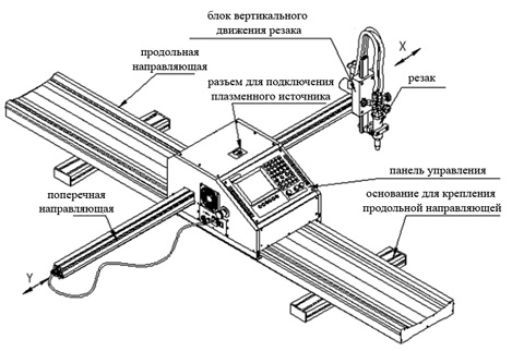
Удобная цифровая панель управления, цифровой дисплей на лицевой панели установки плазменной резки и раскроя листового металла отображает.
Комментарии (0)Просмотров (135)
-
ООО Компания Рамтом
- Новичок
- Сообщения: 10
- Зарегистрирован: 31 июл 2014, 11:29
- Репутация: 0
- Контактная информация:
Помогите по Fastcam`у
Добрый день.
На работе купили станок с программой Fastcam для резки фланцев.
Проблема заключается в том, что во время резки металла нужной формы («свои» модели самого станка). Лазер не до конца прорезает металл.
В чем проблема???
У продавца спрашивать бесполезно)))
фото прилагаем)))
- Вложения
-
-

Nick
- Мастер
- Сообщения: 22776
- Зарегистрирован: 23 ноя 2009, 16:45
- Репутация: 1735
- Заслуга: Developer
- Откуда: Gatchina, Saint-Petersburg distr., Russia
- Контактная информация:

Re: Помогите по Fastcam`у
Сообщение
Nick » 31 июл 2014, 11:47
Может это у него прожиг такой длинный… т.е. нужен вход в траекторию или задержка на прожиг…
-
ООО Компания Рамтом
- Новичок
- Сообщения: 10
- Зарегистрирован: 31 июл 2014, 11:29
- Репутация: 0
- Контактная информация:
Re: Помогите по Fastcam`у
Сообщение
ООО Компания Рамтом » 31 июл 2014, 11:59
Nick писал(а):Может это у него прожиг такой длинный… т.е. нужен вход в траекторию или задержка на прожиг…
По монитору показывает все точки захода доведенные до конца.
Задержка на прожиг где устанавливается, случайно не подскажите???
-
Nick
- Мастер
- Сообщения: 22776
- Зарегистрирован: 23 ноя 2009, 16:45
- Репутация: 1735
- Заслуга: Developer
- Откуда: Gatchina, Saint-Petersburg distr., Russia
- Контактная информация:
Re: Помогите по Fastcam`у
Сообщение
Nick » 31 июл 2014, 12:05
лучше всего сделать небольшие отрезки для входа в траектррию…
-
Nick
- Мастер
- Сообщения: 22776
- Зарегистрирован: 23 ноя 2009, 16:45
- Репутация: 1735
- Заслуга: Developer
- Откуда: Gatchina, Saint-Petersburg distr., Russia
- Контактная информация:
Re: Помогите по Fastcam`у
Сообщение
Nick » 31 июл 2014, 12:14
Может они коротковаты, а то на реальном резе их как бы нет…
И вот там сверху еще написано pierce — это по идее прожиг…
-
ООО Компания Рамтом
- Новичок
- Сообщения: 10
- Зарегистрирован: 31 июл 2014, 11:29
- Репутация: 0
- Контактная информация:
Re: Помогите по Fastcam`у
Сообщение
ООО Компания Рамтом » 31 июл 2014, 12:19
Nick писал(а):Может они коротковаты, а то на реальном резе их как бы нет…
И вот там сверху еще написано pierce — это по идее прожиг…
Спасибо попробуем))) а pierce как изменить??? ![]() ))))
))))
-

artem44ik
- Мастер
- Сообщения: 359
- Зарегистрирован: 27 ноя 2012, 14:29
- Репутация: 16
- Настоящее имя: Скляров Артем Григорьевич
- Откуда: Краснодар
- Контактная информация:

Re: Помогите по Fastcam`у
Сообщение
artem44ik » 31 июл 2014, 12:32
Я с лазером не работал но вот с плазмой пришлось возится, если смотреть на фото то траектория отверстия не совсем правильная, измените скорость, сделайте задержку на прожиге! если судить по шлаку то скорость подачи маленькая, по крайне мере на плазме так!
Идем все к лучшему!
-
artem44ik
- Мастер
- Сообщения: 359
- Зарегистрирован: 27 ноя 2012, 14:29
- Репутация: 16
- Настоящее имя: Скляров Артем Григорьевич
- Откуда: Краснодар
-
Контактная информация:
Re: Помогите по Fastcam`у
Сообщение
artem44ik » 31 июл 2014, 12:38
ООО Компания Рамтом писал(а):Вы имеете ввиду дуги???
На фото видно большие отступы (недорезы) в отверстиях, так точно не должно! Там ни как нельзя сделать вход по дуге?
Идем все к лучшему!
-
ООО Компания Рамтом
- Новичок
- Сообщения: 10
- Зарегистрирован: 31 июл 2014, 11:29
- Репутация: 0
- Контактная информация:
-

Predator
- Мастер
- Сообщения: 9580
- Зарегистрирован: 18 июл 2013, 18:26
- Репутация: 2531
- Контактная информация:

Re: Помогите по Fastcam`у
Сообщение
Predator » 01 авг 2014, 08:09
ООО Компания Рамтом писал(а):
может быть Вы смогли бы прийти к нам
Навряд-ли это у них получится, один в Краснодаре, другой в Питере, а вы как я понимаю из Томска?
-
ООО Компания Рамтом
- Новичок
- Сообщения: 10
- Зарегистрирован: 31 июл 2014, 11:29
- Репутация: 0
- Контактная информация:
-

Fisher
- Почётный участник

- Сообщения: 3391
- Зарегистрирован: 09 апр 2012, 12:39
- Репутация: 424
- Откуда: Киров
- Контактная информация:


Re: Помогите по Fastcam`у
Сообщение
Fisher » 01 авг 2014, 10:58
ООО Компания Рамтом писал(а):между плазмой и листом?
Вы-ж говорили, что лазером режете
www.cncru.ru — все виды станков с ЧПУ. Комплектующие.
-
artem44ik
- Мастер
- Сообщения: 359
- Зарегистрирован: 27 ноя 2012, 14:29
- Репутация: 16
- Настоящее имя: Скляров Артем Григорьевич
- Откуда: Краснодар
- Контактная информация:
Re: Помогите по Fastcam`у
Сообщение
artem44ik » 01 авг 2014, 15:32
ООО Компания Рамтом писал(а):между лазером и листом
А рез так сильно похож на плазму, прям как будто ей и режут, а у вас мануала к вашему станку нет А то полезно иногда читать
Идем все к лучшему!
-
ООО Компания Рамтом
- Новичок
- Сообщения: 10
- Зарегистрирован: 31 июл 2014, 11:29
- Репутация: 0
- Контактная информация:
Re: Помогите по Fastcam`у
Сообщение
ООО Компания Рамтом » 04 авг 2014, 07:05
artem44ik писал(а):
ООО Компания Рамтом писал(а):между лазером и листом
А рез так сильно похож на плазму, прям как будто ей и режут, а у вас мануала к вашему станку нет А то полезно иногда читать
Если бы была, читали бы
-
artem44ik
- Мастер
- Сообщения: 359
- Зарегистрирован: 27 ноя 2012, 14:29
- Репутация: 16
- Настоящее имя: Скляров Артем Григорьевич
- Откуда: Краснодар
- Контактная информация:
Re: Помогите по Fastcam`у
Сообщение
artem44ik » 05 авг 2014, 16:14
Как у вас сам станок называется?
Идем все к лучшему!
-
artem44ik
- Мастер
- Сообщения: 359
- Зарегистрирован: 27 ноя 2012, 14:29
- Репутация: 16
- Настоящее имя: Скляров Артем Григорьевич
- Откуда: Краснодар
- Контактная информация:
Re: Помогите по Fastcam`у
Сообщение
artem44ik » 05 авг 2014, 16:19
И вот мануал к самой программе Fastcam
- Вложения
-
- FastCAM.rar
- (3.94 МБ) 2318 скачиваний
Идем все к лучшему!