Уважаемые дамы и господа! В данной статье описывается FMC для вс Boeing 737. Статья представляет собой инструкцию, описание по работе с FMC. Данная статья будет полезна прежде всего новичкам, но и повторить ее асам и гуру тоже будет полезно. Данная статья — из книги «737.Мой первый лайнер» господина Малухина, поэтому все благодарности прежде всего ему, а потом уже мне. Итак поехали.
1. Все нижеизложенное относится к FMC от компании GE Aviation, (бывшей Smiths Industries), которым комплектуются самолеты типа Boeing 737. Что-то из описываемого вы увидите на «Классике», что-то на NG.
2. Надо сказать, что FMC от GE Aviation применяются и на Boeing и на Airbus, и на Bombardier и т. д. Интерфейсы могут отличаться, но принцип работы един для всех.
3. Наличие тех или иных функций в вашем симе определяется не столько типом FMC, сколько его изготовителем: Wilco, PDMG, LEVEL-D и так далее. Многие функции и опции будут просто мертвы, потому что изготовитель посчитал их ненужными для вирпила.
О терминологии:
Она может быть неправильной, но она – моя. И на этом языке я буду говорить.
На передней электронной панели в кабине есть прибор, похожий на большой калькулятор с квадратным экраном. Это CDU – Central Display Unit. FMC находится в глубоких недрах нашего крафта и выглядит совершенно непримечательно. FMC управляется через CDU. В принципе, назвать CDU FMCом – тоже самое, что назвать клавиатуру компьютером.
Тем не менее, я буду так делать. Я буду называть комплекс CDU-FMC просто – FMC. Я буду говорить: «забить в FMC», «на экране FMC» и так далее.
На панели FMC есть кнопки: с буквами, с цифрами и с сокращениями. Например, CLB, DEP, ARR и так далее. То, что скрывается за кнопками с сокращениями, я буду называть «РАЗДЕЛАМИ». В разделах может быть несколько СТРАНИЦ. Они листаются кнопками NEXT PAGE и PREV PAGE. Кнопки с буквами и цифрами я буду называть «КЛАВИАТУРОЙ».
Внизу экрана FMC есть строка, где появляются буквы и цифры, которые мы набираем на клавиатуре. В документации эта строка называется «Scratchpad». Я же буду называть ее «КОМАНДНАЯ СТРОКА».
Набранное в командной строке может вставляться в ЯЧЕЙКИ, которых мы имеем по 6 штук с каждой стороны экрана. Возле каждой ячейки есть КЛАВИША ЯЧЕЙКИ. Клавишами ячейки мы и вставляем в ячейки данные из командной строки, или наоборот – копируем данные из ячейки в командную строку.
Оглавление:
Разделы LEGS и RTE part1
Разделы LEGS и RTE part2
Редактирование раздела LEGS part1
Редактирование раздела LEGS part2
Раздел N1 LIMIT
Раздел CLIMB
Раздел CRUISE
Раздел DESCENT
Раздел DES — интерфейс
Раздел DES — страница FORECASTS
Раздел FIX
Раздел PROG
Advanced FMC
Оглавление
Разделы LEGS и RTE
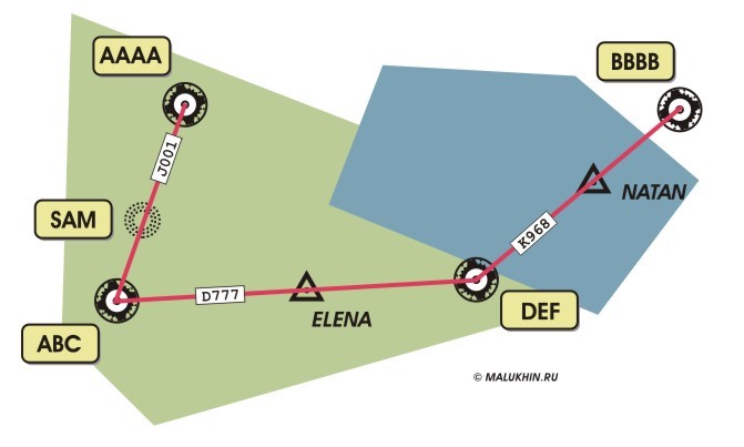
Наш маршрут прописан в 2 разделах: RTE и LEGS. Очевидная разница между ними заключается в следующем: Раздел LEGS показывает все до единой точки (FIX) нашего маршрута, а раздел RTE только основные, плюс имена трасс, соединяющих эти точки.
И именно с RTE работает пилот, когда вручную забивает свой полетный план.
Например, есть такой маршрут:
Как описывает это RTE:

Другими словами:

То есть мы видим перечень основных точек пути с указанием трассы. RTE описывает основные точки пути горизонтального маршрута.
Как все это описывает LEGS:
Так это выглядит на мониторе FMC:
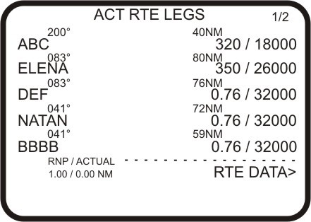
Таким образом, раздел LEGS описывает не только подробный горизонтальный, но и подробный вертикальный маршрут. LEGS – самое подробное описание маршрута. Здесь мы можем полноценно редактировать маршрут: добавлять точки и удалять их. С этим разделом и поработаем.
Внизу экрана:
RTE DATA — переход в раздел RTE.
RNP — Required Navigation Performance. Об этом — в другой главе.
Advanced FMC
Оглавление
Редактирование раздела LEGS
Можно просто добавить в маршрут точку, когда у нее есть идентификатор (ULLI, NAKAT, KRK и т.п.), и точка эта есть в базе данных.
Как быть, если наша точка безымянна? Вот предлагаемая ситуация:
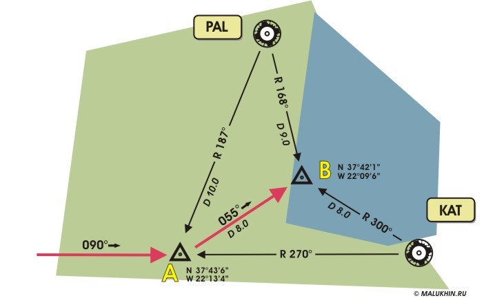
Здесь самой интересной является точка «В». Она безымянна и в базе FMC ее не найти. Как вставить ее в наш маршрут?
Способ 1.
На карте есть ее координаты. И в FMC она будет иметь следующий вид:
N37421W022096
Обратите внимание, что градусы в долготе всегда имеют три знака.
Способ 2.
Точку можно описать радиалом и расстоянием от точки, которая есть в базе. В нашем случае, точки PAL и КАТ в базе есть. Таким образом точка «В» может быть:
КАТ300/8
или
PAL168/9
, где «168» – радиал, а «9» — расстояние от VOR PAL.
То есть, по логике:
PAL/9 – все точки от PAL в радиусе 9 миль, то есть круг. А
PAL168 – все точки на радиале 168 от PAL.
Но только «по логике», т.к. это к разделу LEGS отношения не имеет.
Надо отметить смешное ограничение. Расстояние можно вводить до 999 миль – это максимальное число.
Способ 3.
Точка «В» находится на пересечении двух радиалов. Поэтому ее можно обозначить так:
КАТ300/PAL168
Другой случай:
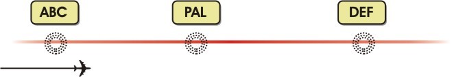
Вот такой маршрут. Нужно добавить две точки. Первую – «А», которая находится за 10 миль ДО VOR PAL и точку «В» — 12 миль ПОСЛЕ VOR PAL. Вот так:
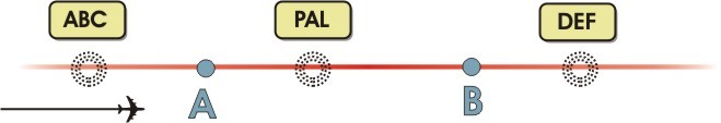
В командной строке FMC пишем:
PAL/-10
, то есть, Недолетая (минус) 10 миль до PAL. Теперь вставляем ее в текущий полетный план, кликая в ТУ ЯЧЕЙКУ, ГДЕ НАХОДИТСЯ ТОЧКА PAL.
По такому же принципу поступаем с точкой «В»:
PAL/+12
Элементарно! «Плюс» — за обозначенной точкой, «минус» — до нее.
Ограничение. Точка, к которой мы привязываем «недолет» — «минус» или «перелет» — «плюс» должна быть частью нашего текущего плана, должна быть в списке LEGS.
Еще несколько фокусов в разделе LEGS.

Допустим нужно лететь от точки SAM до точки DEF, минуя все остальные. Можно сделать это кнопкой DELETE. Но придется удалять каждую точку (ABC, ELENA) по отдельности. Поэтому лучше сделать проще: набрать в командной строке DEF и вставить ее в ячейку сразу после SAM.
Прежде чем нажать кнопку EXEC, обратите внимание, что справа внизу на экране FMC появилась новая функция:
INTC CRS >
Расшифровывается как «Intercept Course». Здесь нам предлагают ввести курс, которым мы пойдем к точке DEF. Ведь по умолчанию наш крафт после SAM полетит прямиком к DEF, а здесь можно изменить курс подхода к этой точке.

То есть в INTC CRS прописываем, например: 340. На MCP отключаем LNAV и в окошке HDG накручиваем, например, 088 — таким курсом мы пойдем к нашему подходу DEF 340. После этого можно смело переключаться обратно на LNAV. Крафт будет двигаться курсом 088 до момента вхождения в курс захвата DEF 340. Потом он развернется и пойдет дальше, согласно маршруту.
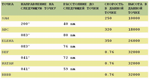
Продолжаем. В разделе LEGS напротив каждой точки стоят и другие важные параметры: расстояние между точками, а также скорость и высота прохождения каждой точки. Расстояние, естественно – величина неизменная, а скорость и высоты можно изменять. Очень полезно уметь этим пользоваться при маневрах в зоне аэропорта, где скорость и эшелоны строго регламентированы. Если вы добавляете в маршрут SID или STAR в разделе ARR/DEP, то все ограничения по высотам и скоростям FMC вставит самостоятельно — в базе все это прописано.
Как прописывать скорости и высоты вручную:
Например:
200/1000
означает скорость 200 узлов на высоте 1000 футов. Скорость/высота – элементарно.
Можно записать так:
/1000
— в ячейке изменится только высота.
Или так:
200
— изменится только скорость.
Высоту, например, 18 000 футов можно прописать как
18000 или
FL180 или
180 – ему все едино.
Если нужно описать не высоту, а ограничение по высоте, то делаем следующее:
Условие «На высоте FL180 или ВЫШЕ» пишется как:
FL180A
«А» означает ABOVE – НАД.
Если «На высоте FL180 или НИЖЕ», то:
FL180B
,где «В» означает BELOW – ПОД.
Дальше – больше. Можно даже обозначить коридор. Например, не ниже FL100 и не выше FL120:

обозначаем как
/100А120В
Далее: Раздел «N1 Limit».
Advanced FMC
Оглавление
Раздел «N1 LIMITS»
Этот раздел содержит настройки режимов работы двигателей. Поскольку FMC – все-таки компьютер, он высчитывает все эти режимы, исходя из массы, температуры, расстояния, давления, стоимости топлива и т.д.
Вот эти режимы:
ТО (сокр. Take Off). Все подробности ниже.
ТО1
ТО2
GA (сокр. Go Around)
CON (сокр. Continuous)
CRZ (сокр. Cruise)
CLB (сокр. Climb)
CLB1
CLB2
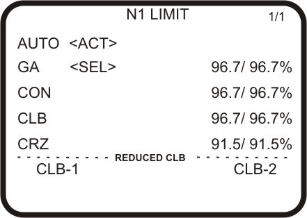
Если на экране FMC напротив режима вы видите <ACT>, то значит этот режим исполняется в настоящее время. <SEL> — выбранный режим. То есть, придет его время, и он станет <ACT>.
Режим ТО (Take Off) – режим взлета. Как он активизируется — знают все: кнопкой TOGA на РУДах. Между тем, до нажатия этой кнопки можно настроить режим в FMC.
ТО – максимальная тяга. ТО1 и ТО2 – уменьшенная тяга.
Специалисты рекомендуют использовать уменьшенную тягу при первой возможности.
Что это дает. Экономию топлива, меньше шума, щадящий режим для двигателей, комфорт для пассажиров. Особенно желательно использование режима в жаркую погоду, когда повышается опасность превышения предела температуры газов за турбиной.
НЕЛЬЗЯ применять метод, если:
— полоса мокрая или
— попутный ветер при взлете или
— проблемы с системой Antiskid – антиюз или
— возможен сдвиг ветра – windshear.
Режим GA (Go Around) – режим ухода на второй круг.
Режим CON (Continuous). То есть режим «Продолжительный». Если двигатели на В737 вывести на 100 процентную мощность, то они вчистую сгорят минуты через три, по-моему. Не знаю, не пробовал. Режим CON – это МАКСИМАЛЬНАЯ БЕЗОПАСНАЯ мощность двигателей. Применяется, как правило, в экстренных ситуациях. Например, при выполнении маневров с одним двигателем.
Режим CRZ (Cruise). Круиз – в смысле: собственно полет. Отрезок пути после набора высоты и до снижения.
Режим CLB (Climb) – набор высоты. Опять же, настоятельно рекомендуется применять режим неполной тяги, то есть CLB 1 или CLB 2. Те же экономия, комфорт, щадящий режим, маневренность и т.п. У пилотов при неполной тяге, будь то взлет или набор высоты больше обзор перед кабиной и больше времени на принятие решений во время такого критического эпизода полета, как взлет.
На CLB 1 крафт на сниженных оборотах (на 8 процентов от нормального CLB) достигает 10 000, затем начинает увеличивать мощность до нормальной.
На CLB 2 крафт на сниженных оборотах (на 16 процентов от нормального CLB) достигает 5 000, затем начинает увеличивать мощность до нормальной.
Нормальная мощность (CLB) достигается на высоте 15 000 в любом варианте.
Режимы ТО доступны при предполетной подготовке.
Режим AUTO – режим по умолчанию, который активируется после выбора VNAV на МСР. В этом режиме FMC по своему усмотрению переключает режимы CRZ – CLB и так далее. Можно отключить его, выбрав любой другой режим простым нажатием.
Далее: Раздел «Climb»
Advanced FMC
Оглавление
Раздел «Climb»
Режим CLIMB активизируется сразу после того, как вы оторвались от земли и включили режим VNAV. Отключается он по достижении точки Т/С (Top of Climb).
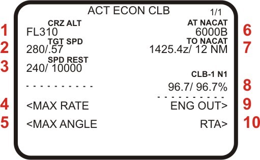
Заголовок раздела (ACT ECON CLB) читается так: «Активный режим — экономичный набор высоты».
1. Заявленный эшелон полета. Та высота, на которую мы, в конечном счете, должны выйти, предел, до которого активным будет режим CLIMB.
2. Скорость экономичного режима. В данной ситуации она не может быть достигнута, поскольку наша высота ниже 6000 футов и есть ограничение по скорости (см. дальше).
3. Ограничение по скорости. Здесь изображено стандартное ограничение: при эшелоне менее FL100 скорость не выше 240 узлов.
Раздел CLIMB (набор высоты) имеет 3 режима набора высоты:
<ECON
<MAX RATE
<MAX ANGLE
ECON – экономичный режим набора высоты – режим по умолчанию. Тут все ясно – самолет будет набирать высоту с такой вертикальной скоростью и с таким углом атаки, чтобы сэкономить максимум топлива.
4. Первая альтернатива режиму ECON – режим MAX RATE, что в нашем случае означает «Максимальная вертикальная скорость».
5. Другая альтернатива – режим MAX ANGLE – «Максимальный угол». Не хватает еще одного слова – «атаки». Максимальный угол атаки. Например, можно быстро взмыть параллельно горному хребту, который возник за торцом полосы.
6. В нашем примере крафт идет на точку NAKAT, где есть ограничение по высоте — не выше 6000 футов.
7. И до точки NAKAT остается 12 миль. Достигнута она будет в 14.24 по времени Zulu.
8. Сейчас активирован режим CLB-1 и N1 равен 96,7 проц.
9. ENG OUT — выход двигателя из строя. После нажатия откроется другая страница и вам предложат выбрать какой из двигателей вышел из строя. После чего вам будет предложена оптимальная высота и скорость для последующих маневров. N1 перейдет в режим CON.
10. RTA — Required Time of Arrival — время требуемое для прибытия в точку. Вызов этой функций отправит вас в раздел PROG (PROGRESS). Его мы рассмотрим ниже.
Данные в пунктах (см. рис.) 1, 2, 3 и 6 можно изменять вручную. Для этого в комнадной строке нужно набрать новый параметр и вставить его в нужную ячейку.
Возможно на вашем МСР есть кнопки SPD INTV и ALT INTV. При активном режиме VNAV окошки IAS/MACH и ALT не показывают ничего. Если нажать кнопки SPD INTV или ALT INTV, то можно вручную изменить параметры через МСР в пунктах 2 и 6 (см. рисунок) соответственно.
Режим CLB переключится автоматом режим CRZ по достижении точки Т/С.
Далее: Раздел CRZ
Advanced FMC
Оглавление
Раздел CRZ
Этот раздел описывает параметры полета на заявленном эшелоне от окончания набора высоты до снижения.
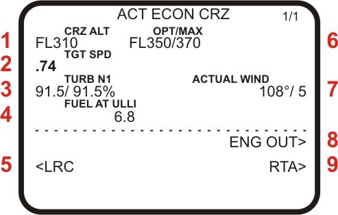
Заголовок (ACT ECON CRZ) читается как «Активен экономный режим полета».
1. Заявленный и текущий эшелон полета.
2. Скорость текущего режима. Имеется ввиду рекомендуемая скорость.
3. Обороты N1, которые потребуется установить после попадания в сильную болтанку (TURB – turbulence) в горизонтальном полете.
4. Количество топлива в тысячах фунтов, которое должно остаться по достижении точки ULLI (аэропорт «Пулково».)
5. LRC — Long Range Cruise. Грубо говоря, «Полет на дальнее расстояние». Режим наименьшего расхода топлива. Меньший расход топлива — ниже скорость. Прежде чем активировать эту функцию посмотрите внимательно на изменения: в остатке топлива в пункте назначения и во времени прибытия. Сравните и подумайте — а стоит ли.
6. OPT/MAX — оптимальный и максимальный эшелоны. Не обольщайтесь — когда FMC вычисляет оптимальный эшелон он не берет в расчет расстояние маршрута. Ему — что от Москвы до Сахалина — что от Москвы до Питера: он высчитывает максимально экономный режим для полета ВС на эшелоне с такой массой, таким ветром, такой конфигурацией и с такими двигателями. Из этих же параметров вычисляется максимальный, предельный эшелон — рубеж, отделяющий вас от катастрофы.
7. Текущий ветер. Параметр FMC проставляет сам, но возможно релактирование вручную.
8 и 9 — об этом говорилось в предыдущем разделе.
Know-How
Для изменения эшелона можно воспользоваться МСР (в простонародье «автопилот»), набрать в окошке новый эшелон и нажать LVL CHG. А можно и даже лучше — иначе.
Снижаемся с 30 000 до 18 000. Для этого набираем в МСР 18 000 (ALT) и смотрим на FMC, там, в командной строке в разделе CRZ это число должно продублироваться. Загоняем 18 000 в ячейку, где находится CRZ ALT, и видим, что в FMC, в разделе CRZ в заголовке произошли изменения: к ACT ECON CRZ добавилась аббревиатура DES. То есть началось снижение, а двигатели пашут в режиме CRZ.
Так стоит менять эшелон тогда, когда это изменения серьезное. Небольшие изменения — футов на 500 – 1000 — лучше делать с помощью настройки вертикальной скорости.
Для чего это надо делать. Если вы вводите кардинальное изменение по эшелону, и это изменение не находит отражения в FMC, то вы теряете вертикальный профиль (эшелоны, скорости и пр.), который FMC аккуратно и тщательно рассчитал, и по которому он держит весь полет.
Далее: Раздел «Descent».
Advanced FMC
Оглавление
Раздел DES
Самый сложный для выполнения режим.
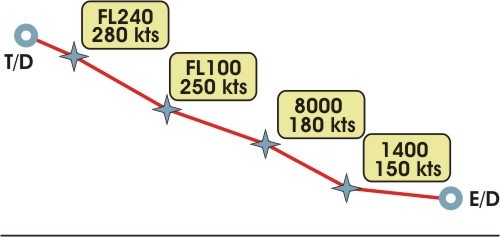
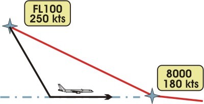
Этап полета под названием Descent начинается с точки T/D (Top of Descent) и заканчивается точкой E/D (End of Descent). Последняя – это либо точка на поверхности ВПП аэродрома назначения, либо точка вхождения в глиссаду.
Из чего складываются и T/D, и Т/С (Top of Climb)? Прежде всего, из ограничений по скорости и высоте (например, SIDs или STARs) и силы и направления ветра. Но, если на Т/С – на финальную точку набора высоты мы почти не обращаем внимания: какая в сущности разница – где мы выйдем на заявленный эшелон. То Top of Descent – точка начала снижения — имеет решающее значение, потому что точка окончания снижения – E/D — жестко фиксирована. Мы имеем четкий отрезок, после вхождения в который который он не может быть сокращен или удлинен. На этом отрезке существуют точки, которые должны быть пройдены с определенной скоростью и на определенной высоте. В этом то и есть главная сложность режима Descent.
Не случайно именно в разделе DES есть страница «FORECASTS» — прогноз погоды, где мы вводим скорость и силу ветра на разных эшелонах. Ввели погоду — T/D передвинулась, ввели STAR — T/D опять передвинулась, ограничение на эшелонах ниже FL100 – снова подвижка.
Сущая правда — FMC в режим DES переходит автоматически. Но для этого за 5, а некоторых типах FMC и за 10 миль до точки T/D на панели МСР (гр. говоря — автопилота) нужно выбрать самую малую высоту, например, высоту превышения аэродрома. Высота, установленная на МСР, в системной иерархии ВСЕГДА имеет приоритет перед FMC.
Когда крафт подошел к точке T/D (и вы готовы к этому – см. выше), то FMC автоматом переключится в раздел DES, и вы увидите заголовок “ACT DES PATH”, что расшифровывается как «Активен режим снижения по траектории».
Вообще, в разделе DES есть два варианта снижения: SPEED и PATH. По умолчанию активизируется PATH – т.е. по траектории, по профилю. Иными словами: по всем точкам подхода, включая STAR, с соблюдением ограничений по высотам в каждой точке.
Суть режима PATH:
— FMC следит за ПРОФИЛЕМ (ТРАЕКТОРИЕЙ) снижения,
— ПИЛОТ следит за СКОРОСТЬЮ.
Гениальный, великолепный, удобнейший режим! Но почему-то в симе все это реализовано как-то кривовато.
Пилот управляет скоростью с помощью интерцепторов (спойлеров) и РУДами. Если скорость становится выше требуемой – притормаживаем интерцепторами, ниже – налегаем на РУДы. И тут оказывается, что в реале или даже в симкабине сделать это проще, чем в FS.
В симкабине притормозить интерцепторами также просто, как почесать ногу – ручка рядом, и хочешь — выпустил на четверть, хочешь – на половину. Легко убрал. В симе, мало того, что работа с интерцепторами крайне неудобна, она еще и не до конца реализована и высчитана при создании модели. Выпустите спойлер в симе – да, крафт притормозит, теперь уберите – и он помчится вперед со всей дурацкой мочи, да еще и тряханет поперечно.
То же самое с РУДами. В реале или симкабине кладешь руку на холодные костяшки, толкаешь, РУДы, мягко сопротивляясь, поддаются — скорость увеличивается. Руку убрал – РУДы плавно возвращаются на место. И все это в режиме VNAV! Попробуйте сделать то же самое в симе. Вот то-то.
Недоработано, вообщем. Вот что пишет Майк Рэй в своей толстой мурзилке «Flying The Boeing 700 Series Flight Simulators» (pg. 205): «I believe that VNAV function of the FMC is so complex and mysterious (подчеркнуто мной), that few if any mere human pilots understand just how it works». Эта «таинственность» — принадлежность именно сима, именно сыроватого, недоработанного софта, и Майк Рэй, я считаю, расписывается в этом.
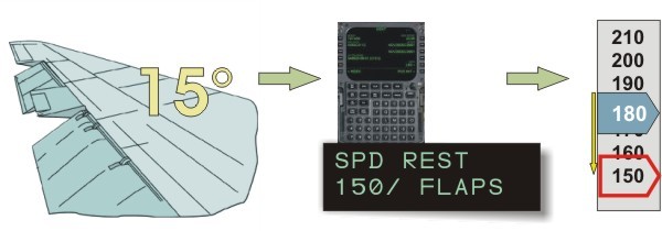
Ну почему не сделать в симе такую простую и крайне полезную вещь, как ограничение скоростей по закрылками, которое находится в прошивке FMC?! Поясню. В разделе DES есть ячейка SPD REST – ограничение по скорости. По умолчанию там стоит 240/10000, то есть скорость 240 на эшелоне до 10000 футов. В реальном FMC в его прошивке забиты еще и ограничения по закрылкам. То есть — рычаг управления закрылками сопряжен с FMC, и, если вы выпустили закрылки на 15 градусов, а по техтребованиям скорость крафта для 15 градусов не должна превышать, допустим, 150 узлов, то на экране FMC в ячейке появится: 150/FLAPS. И теперь ЗАДАННОЙ скоростью будет 150 узлов. Крафт будет стремиться замедлиться до этой отметки. Ничего не нужно подсчитывать, подглядывать в шпаргалку. Но в симе такой простой вещи нет.
ОК. Оставим обиды. Дальше. Вторым режимом снижения является режим SPD – SPEED.
В режиме SPD:
— FMC следит за СКОРОСТЬЮ,
— ПИЛОТ следит за ПРОФИЛЕМ (ТРАЕКТОРИЕЙ).
То есть – режим противоположный режиму PATH.
Чтобы управлять самолетом в траектории используются те же средства: РУДы и интерцепторы.
В некоторых моделях крафтов есть интересная фишка. Если вы снизились не в нужной точке, а раньше, чем нужно, то крафт перейдет в горизонтальный режим полета, долетит до точки и лишь потом позволит продолжить снижение.
Если вы находитесь в радиусе 50 миль от T/D (Top of Descent), то на экране FMC появляется функция DES NOW> — «Начать снижение незамедлительно». Крафт начнет снижение с вертикальной скоростью около 1000 фут/мин.
Иногда на этой странице в командной строке может появиться предупреждение: DRAG REQUIRED. Это FMC просит торможения. Интерцепторами, разумеется.
Отключается режим DES по достижении точки входа в глиссаду.
Далее: Раздел DES — интерфейс
Advanced FMC
Оглавление
Раздел DES — интерфейс
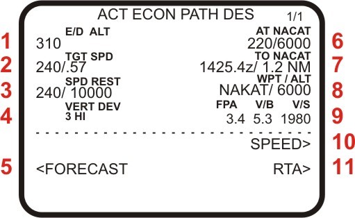
Заголовок следует читать так: «Активен экономичный режим снижения по траектории».
1. Высота конечной точки снижения — End fo Descent.
2. Текущая, экономичная скорость.
3. Ограничение по скорости.
4. Вертикальная девиация — на сколько по вертикали крафт отклонился от траектории. Hi — higher — выше, чем требуется.
5. Переход в раздел Forecasts — прогнозы погоды.
6. Ближайшее ограничение: в точке NAKAT скорость 220 при высоте 6000 футов.
7. До ближайшей точки (NAKAT) осталось 1,2 мили и будем мы там в 14:25 по Зулу.
8. В ближайшей точке высота должна быть 6000 футов.
9. FPA — Flight Path Angle — угол между вертикальным направлением ВС и поверхностью земли.
V/B — вертикальное направление от текущей позиции до следующей точки.
V/S — вертикальная скорость.
10. Переключение в режим SPEED DESCENT.
11. RTA — Required Time of Arrival — переключает в раздел PROGRESS.
Далее: Раздел DES — страница FORECASTS
Advanced FMC
Оглавление
Раздел DES — страница FORECASTS
Как было сказано выше, страница Forecasts (прогноз погоды) раздела Descent помогает сделать этот самый Descent еще более приятным. После заполнения страницы точка T/D обязательно передвинется – и это правильно, так как FMC высчитал точное снижение с учетом ветров.
Что тут написано?
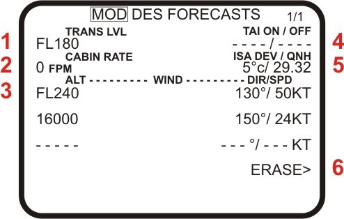
Читаем заголовок: «Изменена страница прогнозов». Это значит, что данные были введены, но они еще не сохранены и не обсчитаны. Для того, чтобы сохранить и MOD (режим редактирования) превратить в ACT (текущий актуальный режим) надо нажать кнопку EXEC. Но это вы, конечно, знаете.
1. Transition Level – эшелон перехода.
2. Cabin Rate – показатель изменения давления в салоне. FPM – Feet per Minute – футов в минуту. Величина с FMC не регулируется — см. оверхэд.
3. Вся строка. Эшелон – скорость и направление ветра на нем. Таких строк три, для трех различных эшелонов. Ключевая строка на этой странице. Исходя из этих данных FMC рассчитывает профиль снижения.
Всех, конечно, интересует, где взять данные для этого пункта: скорость и направления ветров на различных эшелонах.
В дефолтном симе этого нет – не ищите. Данные, которые передает ATIS, сюда не годятся, так как они передают ветра на таких высотах, где снижение – DESCENT – уже фактически окончилось.
В реале пилоты используют ACARS. Для нас же остается гуглить на словосочетание «Winds aloft», а может и вовсе забыть об этой опции – ни в одном из популярных симов она не реализована.
4. TAI ON/OFF. TAI — Thermal Anti-Ice. В этой ячейке вводятся данные – эшелоны — для включения-выключения системы Anti-ice. Это имеет значение при расчете снижения, т.к. вкл/выкл Anti-ice влияет на параметры работы двигателей. Слушайте ATIS.
5. ISA DEV / QNH. ISA — International Standard Atmosphere – атмосферный стандарт (МСА – по-нашему). ISA это 15 градусов Цельсия при давлении 29.92 на уровне моря. DEV – deviation – отклонение. До слэша эту ячейку следует читать так: Отклонение от Стандартной температуры на эшелоне (НЕ В ПОРТУ ПРИБЫТИЯ!). После слэша — давление в порту прибытия (над уровнем моря).
Отклонение от Стандартной температуры равняется разнице между забортной температурой и Стандартной температурой для данного эшелона.
Стандартная температура изменяется на 2 градуса по Цельсию каждую вертикальную тысячу футов (в Имперской системе) или на 6,5 градусов на каждый километр (в Метрической системе). То есть на эшелоне FL300 Стандартная температура составит
30 х 2 = 60
15 — 60= — 45С
Если за бортом -55С, то девиация будет равна:
-45 – (-55) = — 10 С
Почему «минус»? Потому -55 холоднее, чем -45.
В любом случае, париться по поводу девиаций не надо, т.к. я не видел ни одного сима, где была бы реализована эта опция. Увы.
6. ERASE – отмена внесенных изменений.
Далее: Раздел FIX.
Advanced FMC
Оглавление
Раздел FIX
Очень полезный раздел. Все, что вы здесь введете, на процесс полета не повлияет, но позволит вам узнать, где находится ЛЮБАЯ точка из базы данных FMC. Причем, вне зависимости от принадлежности к вашему маршруту.
Вы получаете: радиал от точки, расстояние до…, время до… и т.п. Кроме того, ТОЧКА эта ОТОБРАЖАЕТСЯ на экране MFD. MFD (Multi-Function Display) — для тех, кто позабыл — дисплей на главной панели с картой маршрута. Будет видна не только сама точка, но и заданные вами радиалы и точки удаления.
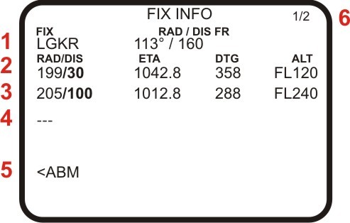
1. Собственно введенная нами точка (FIX). В это же строке: радиал и расстояние от нее (FR — «from»).
2. В эту ячейку пользователь вводит РАДИАЛ / ДИСТАНЦИЮ. Причем можно ввести что-то одно. Например, только радиал (199) или только расстояние (/30). На рисунке: пользователь ввел расстояние (/30), а FMC рассчитал радиал от LGKR на удалении 30 миль от LGKR ПО ПОЛЕТНОМУ ПЛАНУ, а не напрямую. Далее в строке — информация о точке, которая находится на расстоянии 30 миль от LGKR и радиалом 199 от LGKR же: ЕТА — ожидаемое время прибытия в эту точку; DTG — расстояние (не по прямой от вашего воздушного судна, а согласно полетного плана); ALT — запланированная высота в этой точке.
Если введенной вами точки в полетном плане нет, то колонки ЕТА, DTG и ALT будут пусты.
3 и 4. Еще две ячейки для ввода радиалов или/и дистанций.
5. ABM – сокращение от Abeam, что переводится как «ТРАВЕРЗ». Имеется ввиду траверз на точку LGKR относительно нашего маршрута. Здесь мы увидим расстояние ДО ТОЧКИ траверза (не до самой точки), время пересечения точки траверза на НАШЕМ МАРШРУТЕ и высоту в этой точке.
6. Мы можем ввести в раздел FIX несколько точек. Для каждой точки своя страница. Обычно их две. Существуют FMC с шестью страницами, для шести точек. И есть с бесконечным количеством страниц, когда при заполнении одной страницы появляется следующая пустая.
Know-How
Для меня это не просто пример – следующие манипуляции выполняются мною в каждом полете.
Необходимое отступление.
1. Обычно снижение с высоты ~ 30 тысяч мы начинаем на удалении ~ 100 миль от аэропорта назначения. Даже тупой дефолтный диспетчер пригласит вас сменить эшелон на этом удалении.
2. Правилом хорошего и безопасного тона считается на удалении 30 миль от аэропорта назначения быть на высоте не более 10 000 и на скорости не выше 250 узлов.
Итак. Запланированный эшелон набран. Ничего не происходит. Вы уже покурили и отметились в туалете. Вот тут и давим кнопку FIX.
Допустим наш аэропорт назначения – «Иоаннис Каподастриас» в городе Керкира (LGKR). В командной строке в разделе FIX пишем «LGKR». Загоняем это в первую ячейку слева и сразу получаем радиал и расстояние до него.
Надо сказать, что в MFD любой аэропорт обозначается не как комплекс сооружений, а как точка.
Далее. В командной строке пишем:
/30
вводим это во вторую ячейку, слева. MFD показал нам все точки, которые находятся на удалении 30 миль от точки LGKR, то есть – круг. Еще пишем:
/100
и вводим в ячейку ниже. Получаем еще один круг с радиусом в 100 миль. На MFD теперь два круга, а мы знаем, когда примерно нужно начинать снижение – за 100 миль – при пересечении большого круга. И мы видим тридцатимильный круг, за которым нам желательно быть на эшелоне FL100 и на скорости до 250 kts.
Если вы закроете раздел FIX в FMC, то вся эта геометрия с MFD никуда не денется, и появление на дисплее зеленого круга будет вам хорошим напоминанием о том, что надо собраться и приготовиться к снижению.
Далее: раздел «Progress»
Advanced FMC
Оглавление
Раздел PROGRESS
Данный раздел предназначен для информирования пилотов о текущем положении воздушного судна относительно заданного маршрута. Вызывается кнопкой «PROG».
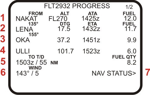
Заголовок читаем так: «Прогресс рейса 2932»
1. Первая строка показывает параметры предыдущей, пройденной точки пути. Читаем строку так:
«Точку «NAKAT» пересекли на эшелоне 27000 футов в 14:25 по времени Zulu. Топлива в тот момент было 12 тысяч фунтов.»
2. Вторая строка. Мы движемся к точке «LENA». Направление на нее 135 градусов, расстояние — 17,5 миль. Ожидаемое время прибытия (ETA) — 14:32 по zulu. Остаток топлива в точке «LENA» — 11700 фунтов.
3. Третья строка показывает точку пути, которая следует за точкой, указанной во второй строке. Строка расшифровывается так же, как и предыдущая.
DTG — Distance To Go — показывает расстояние не по прямой, а согласно нашего маршрута.
4. Строка показывает конечный пункт нашего полета. До ULLI (Пулково) — 101,7 миль. Ожидаемое время прибытия — 15:23. Топлива должно остаться 6 тысяч фунтов.
Если количество топлива в этой ячейке меньше, чем указано в ячейке «RESERVES» раздела PERF INIT, то в командной строке появится сообщение «USG RESERVE FUEL» — «Использую резервное топливо».
5. Строка показывает расстояние, ожидаемое время прибытия и количество топлива в точке Top Of Descent — точке начала снижения.
6. Текущий ветер: скорость и направление. Данные вводятся без вашего участия.
7. Переход на страницу «NAV STATUS». Страница указывает информацию, относящуюся к IRS: источники радиосигналов и данные GPS приемников, на которые опирается IRS в счислении текущего места воздушного судна.
Огромное спасибо господину Малухину за материал, ну и в последнюю очередь мне.
На всякий случай ссылки: официальный сайт господина Малухина оригинальная статья ссылка на топик в форуме.
Suggest us how to improve StudyLib
(For complaints, use
another form
)
Your e-mail
Input it if you want to receive answer
Rate us
1
2
3
4
5
Инструкция по работе с разделами FMC для Боинга 737 Advanced FMC Boeing 737
Уважаемые дамы и господа! В данной статье описывается FMC для вс Boeing 737. Статья представляет собой инструкцию, описание по работе с FMC. Данная статья будет полезна прежде всего новичкам, но и повторить ее асам и гуру тоже будет полезно. Данная статья — из книги «737.Мой первый лайнер» господина Малухина, поэтому все благодарности прежде всего ему, а потом уже мне. Итак поехали.
1. Все нижеизложенное относится к FMC от компании GE Aviation, (бывшей Smiths Industries), которым комплектуются самолеты типа Boeing 737. Что-то из описываемого вы увидите на «Классике», что-то на NG.
2. Надо сказать, что FMC от GE Aviation применяются и на Boeing и на Airbus, и на Bombardier и т. д. Интерфейсы могут отличаться, но принцип работы един для всех.
3. Наличие тех или иных функций в вашем симе определяется не столько типом FMC, сколько его изготовителем: Wilco, PDMG, LEVEL-D и так далее. Многие функции и опции будут просто мертвы, потому что изготовитель посчитал их ненужными для вирпила.
Она может быть неправильной, но она – моя. И на этом языке я буду говорить.
На передней электронной панели в кабине есть прибор, похожий на большой калькулятор с квадратным экраном. Это CDU – Central Display Unit. FMC находится в глубоких недрах нашего крафта и выглядит совершенно непримечательно. FMC управляется через CDU. В принципе, назвать CDU FMCом – тоже самое, что назвать клавиатуру компьютером.
Тем не менее, я буду так делать. Я буду называть комплекс CDU-FMC просто – FMC. Я буду говорить: «забить в FMC», «на экране FMC» и так далее.
На панели FMC есть кнопки: с буквами, с цифрами и с сокращениями. Например, CLB, DEP, ARR и так далее. То, что скрывается за кнопками с сокращениями, я буду называть «РАЗДЕЛАМИ». В разделах может быть несколько СТРАНИЦ. Они листаются кнопками NEXT PAGE и PREV PAGE. Кнопки с буквами и цифрами я буду называть «КЛАВИАТУРОЙ».
Внизу экрана FMC есть строка, где появляются буквы и цифры, которые мы набираем на клавиатуре. В документации эта строка называется «Scratchpad». Я же буду называть ее «КОМАНДНАЯ СТРОКА».
Набранное в командной строке может вставляться в ЯЧЕЙКИ, которых мы имеем по 6 штук с каждой стороны экрана. Возле каждой ячейки есть КЛАВИША ЯЧЕЙКИ. Клавишами ячейки мы и вставляем в ячейки данные из командной строки, или наоборот – копируем данные из ячейки в командную строку.
Редактирование раздела LEGS part1
Редактирование раздела LEGS part2
Раздел DES — страница FORECASTS
Наш маршрут прописан в 2 разделах: RTE и LEGS. Очевидная разница между ними заключается в следующем: Раздел LEGS показывает все до единой точки (FIX) нашего маршрута, а раздел RTE только основные, плюс имена трасс, соединяющих эти точки.
И именно с RTE работает пилот, когда вручную забивает свой полетный план.
Например, есть такой маршрут:
То есть мы видим перечень основных точек пути с указанием трассы. RTE описывает основные точки пути горизонтального маршрута.
Как все это описывает LEGS:
Так это выглядит на мониторе FMC:
Таким образом, раздел LEGS описывает не только подробный горизонтальный, но и подробный вертикальный маршрут. LEGS – самое подробное описание маршрута. Здесь мы можем полноценно редактировать маршрут: добавлять точки и удалять их. С этим разделом и поработаем.
RTE DATA — переход в раздел RTE.
RNP — Required Navigation Performance. Об этом — в другой главе.
Редактирование раздела LEGS
Можно просто добавить в маршрут точку, когда у нее есть идентификатор (ULLI, NAKAT, KRK и т.п.), и точка эта есть в базе данных.
Как быть, если наша точка безымянна? Вот предлагаемая ситуация:
Здесь самой интересной является точка «В». Она безымянна и в базе FMC ее не найти. Как вставить ее в наш маршрут?
Способ 1. На карте есть ее координаты. И в FMC она будет иметь следующий вид:
Обратите внимание, что градусы в долготе всегда имеют три знака.
Способ 2. Точку можно описать радиалом и расстоянием от точки, которая есть в базе. В нашем случае, точки PAL и КАТ в базе есть. Таким образом точка «В» может быть:
, где «168» – радиал, а «9» — расстояние от VOR PAL.
То есть, по логике: PAL/9 – все точки от PAL в радиусе 9 миль, то есть круг. А PAL168 – все точки на радиале 168 от PAL. Но только «по логике», т.к. это к разделу LEGS отношения не имеет.
Надо отметить смешное ограничение. Расстояние можно вводить до 999 миль – это максимальное число.
Способ 3. Точка «В» находится на пересечении двух радиалов. Поэтому ее можно обозначить так:
Вот такой маршрут. Нужно добавить две точки. Первую – «А», которая находится за 10 миль ДО VOR PAL и точку «В» — 12 миль ПОСЛЕ VOR PAL. Вот так:
В командной строке FMC пишем:
, то есть, Недолетая (минус) 10 миль до PAL. Теперь вставляем ее в текущий полетный план, кликая в ТУ ЯЧЕЙКУ, ГДЕ НАХОДИТСЯ ТОЧКА PAL.
По такому же принципу поступаем с точкой «В»:
Элементарно! «Плюс» — за обозначенной точкой, «минус» — до нее.
Ограничение. Точка, к которой мы привязываем «недолет» — «минус» или «перелет» — «плюс» должна быть частью нашего текущего плана, должна быть в списке LEGS.
Еще несколько фокусов в разделе LEGS.
Допустим нужно лететь от точки SAM до точки DEF, минуя все остальные. Можно сделать это кнопкой DELETE. Но придется удалять каждую точку (ABC, ELENA) по отдельности. Поэтому лучше сделать проще: набрать в командной строке DEF и вставить ее в ячейку сразу после SAM.
Прежде чем нажать кнопку EXEC, обратите внимание, что справа внизу на экране FMC появилась новая функция:
Расшифровывается как «Intercept Course». Здесь нам предлагают ввести курс, которым мы пойдем к точке DEF. Ведь по умолчанию наш крафт после SAM полетит прямиком к DEF, а здесь можно изменить курс подхода к этой точке.
То есть в INTC CRS прописываем, например: 340. На MCP отключаем LNAV и в окошке HDG накручиваем, например, 088 — таким курсом мы пойдем к нашему подходу DEF 340. После этого можно смело переключаться обратно на LNAV. Крафт будет двигаться курсом 088 до момента вхождения в курс захвата DEF 340. Потом он развернется и пойдет дальше, согласно маршруту.
Продолжаем. В разделе LEGS напротив каждой точки стоят и другие важные параметры: расстояние между точками, а также скорость и высота прохождения каждой точки. Расстояние, естественно – величина неизменная, а скорость и высоты можно изменять. Очень полезно уметь этим пользоваться при маневрах в зоне аэропорта, где скорость и эшелоны строго регламентированы. Если вы добавляете в маршрут SID или STAR в разделе ARR/DEP, то все ограничения по высотам и скоростям FMC вставит самостоятельно — в базе все это прописано. Как прописывать скорости и высоты вручную:
означает скорость 200 узлов на высоте 1000 футов. Скорость/высота – элементарно.
— в ячейке изменится только высота.
— изменится только скорость.
Высоту, например, 18 000 футов можно прописать как
Если нужно описать не высоту, а ограничение по высоте, то делаем следующее:
Условие «На высоте FL180 или ВЫШЕ» пишется как:
Если «На высоте FL180 или НИЖЕ», то:
,где «В» означает BELOW – ПОД.
Дальше – больше. Можно даже обозначить коридор. Например, не ниже FL100 и не выше FL120:
Этот раздел содержит настройки режимов работы двигателей. Поскольку FMC – все-таки компьютер, он высчитывает все эти режимы, исходя из массы, температуры, расстояния, давления, стоимости топлива и т.д.
Вот эти режимы: ТО (сокр. Take Off). Все подробности ниже. ТО1 ТО2 GA (сокр. Go Around) CON (сокр. Continuous) CRZ (сокр. Cruise) CLB (сокр. Climb) CLB1 CLB2
Режим ТО (Take Off) – режим взлета. Как он активизируется — знают все: кнопкой TOGA на РУДах. Между тем, до нажатия этой кнопки можно настроить режим в FMC. ТО – максимальная тяга. ТО1 и ТО2 – уменьшенная тяга.
Специалисты рекомендуют использовать уменьшенную тягу при первой возможности.
Что это дает. Экономию топлива, меньше шума, щадящий режим для двигателей, комфорт для пассажиров. Особенно желательно использование режима в жаркую погоду, когда повышается опасность превышения предела температуры газов за турбиной.
НЕЛЬЗЯ применять метод, если: — полоса мокрая или — попутный ветер при взлете или — проблемы с системой Antiskid – антиюз или — возможен сдвиг ветра – windshear.
Режим GA (Go Around) – режим ухода на второй круг.
Режим CON (Continuous). То есть режим «Продолжительный». Если двигатели на В737 вывести на 100 процентную мощность, то они вчистую сгорят минуты через три, по-моему. Не знаю, не пробовал. Режим CON – это МАКСИМАЛЬНАЯ БЕЗОПАСНАЯ мощность двигателей. Применяется, как правило, в экстренных ситуациях. Например, при выполнении маневров с одним двигателем.
Режим CRZ (Cruise). Круиз – в смысле: собственно полет. Отрезок пути после набора высоты и до снижения.
Режим CLB (Climb) – набор высоты. Опять же, настоятельно рекомендуется применять режим неполной тяги, то есть CLB 1 или CLB 2. Те же экономия, комфорт, щадящий режим, маневренность и т.п. У пилотов при неполной тяге, будь то взлет или набор высоты больше обзор перед кабиной и больше времени на принятие решений во время такого критического эпизода полета, как взлет.
На CLB 1 крафт на сниженных оборотах (на 8 процентов от нормального CLB) достигает 10 000, затем начинает увеличивать мощность до нормальной. На CLB 2 крафт на сниженных оборотах (на 16 процентов от нормального CLB) достигает 5 000, затем начинает увеличивать мощность до нормальной. Нормальная мощность (CLB) достигается на высоте 15 000 в любом варианте.
Режимы ТО доступны при предполетной подготовке.
Режим AUTO – режим по умолчанию, который активируется после выбора VNAV на МСР. В этом режиме FMC по своему усмотрению переключает режимы CRZ – CLB и так далее. Можно отключить его, выбрав любой другой режим простым нажатием.
Режим CLIMB активизируется сразу после того, как вы оторвались от земли и включили режим VNAV. Отключается он по достижении точки Т/С (Top of Climb).
Заголовок раздела (ACT ECON CLB) читается так: «Активный режим — экономичный набор высоты».
1. Заявленный эшелон полета. Та высота, на которую мы, в конечном счете, должны выйти, предел, до которого активным будет режим CLIMB.
2. Скорость экономичного режима. В данной ситуации она не может быть достигнута, поскольку наша высота ниже 6000 футов и есть ограничение по скорости (см. дальше).
3. Ограничение по скорости. Здесь изображено стандартное ограничение: при эшелоне менее FL100 скорость не выше 240 узлов.
Раздел CLIMB (набор высоты) имеет 3 режима набора высоты:
— «Начать снижение незамедлительно». Крафт начнет снижение с вертикальной скоростью около 1000 фут/мин.
Иногда на этой странице в командной строке может появиться предупреждение: DRAG REQUIRED. Это FMC просит торможения. Интерцепторами, разумеется.
Отключается режим DES по достижении точки входа в глиссаду.
Далее: Раздел DES — интерфейс
Заголовок следует читать так: «Активен экономичный режим снижения по траектории».
1. Высота конечной точки снижения — End fo Descent.
2. Текущая, экономичная скорость.
3. Ограничение по скорости.
4. Вертикальная девиация — на сколько по вертикали крафт отклонился от траектории. Hi — higher — выше, чем требуется.
5. Переход в раздел Forecasts — прогнозы погоды.
6. Ближайшее ограничение: в точке NAKAT скорость 220 при высоте 6000 футов.
7. До ближайшей точки (NAKAT) осталось 1,2 мили и будем мы там в 14:25 по Зулу.
8. В ближайшей точке высота должна быть 6000 футов.
9. FPA — Flight Path Angle — угол между вертикальным направлением ВС и поверхностью земли.
V/B — вертикальное направление от текущей позиции до следующей точки.
V/S — вертикальная скорость.
10. Переключение в режим SPEED DESCENT.
11. RTA — Required Time of Arrival — переключает в раздел PROGRESS.
Далее: Раздел DES — страница FORECASTS
Раздел DES — страница FORECASTS
Как было сказано выше, страница Forecasts (прогноз погоды) раздела Descent помогает сделать этот самый Descent еще более приятным. После заполнения страницы точка T/D обязательно передвинется – и это правильно, так как FMC высчитал точное снижение с учетом ветров.
Читаем заголовок: «Изменена страница прогнозов». Это значит, что данные были введены, но они еще не сохранены и не обсчитаны. Для того, чтобы сохранить и MOD (режим редактирования) превратить в ACT (текущий актуальный режим) надо нажать кнопку EXEC. Но это вы, конечно, знаете.
2. Cabin Rate – показатель изменения давления в салоне. FPM – Feet per Minute – футов в минуту. Величина с FMC не регулируется — см. оверхэд.
3. Вся строка. Эшелон – скорость и направление ветра на нем. Таких строк три, для трех различных эшелонов. Ключевая строка на этой странице. Исходя из этих данных FMC рассчитывает профиль снижения.
Всех, конечно, интересует, где взять данные для этого пункта: скорость и направления ветров на различных эшелонах.
В дефолтном симе этого нет – не ищите. Данные, которые передает ATIS, сюда не годятся, так как они передают ветра на таких высотах, где снижение – DESCENT – уже фактически окончилось.
В реале пилоты используют ACARS. Для нас же остается гуглить на словосочетание «Winds aloft», а может и вовсе забыть об этой опции – ни в одном из популярных симов она не реализована.
4. TAI ON/OFF. TAI — Thermal Anti-Ice. В этой ячейке вводятся данные – эшелоны — для включения-выключения системы Anti-ice. Это имеет значение при расчете снижения, т.к. вкл/выкл Anti-ice влияет на параметры работы двигателей. Слушайте ATIS.
5. ISA DEV / QNH. ISA — International Standard Atmosphere – атмосферный стандарт (МСА – по-нашему). ISA это 15 градусов Цельсия при давлении 29.92 на уровне моря. DEV – deviation – отклонение. До слэша эту ячейку следует читать так: Отклонение от Стандартной температуры на эшелоне (НЕ В ПОРТУ ПРИБЫТИЯ!). После слэша — давление в порту прибытия (над уровнем моря).
Отклонение от Стандартной температуры равняется разнице между забортной температурой и Стандартной температурой для данного эшелона.
Стандартная температура изменяется на 2 градуса по Цельсию каждую вертикальную тысячу футов (в Имперской системе) или на 6,5 градусов на каждый километр (в Метрической системе). То есть на эшелоне FL300 Стандартная температура составит 30 х 2 = 60 15 — 60= — 45С Если за бортом -55С, то девиация будет равна: -45 – (-55) = — 10 С Почему «минус»? Потому -55 холоднее, чем -45.
В любом случае, париться по поводу девиаций не надо, т.к. я не видел ни одного сима, где была бы реализована эта опция. Увы.
6. ERASE – отмена внесенных изменений.
Очень полезный раздел. Все, что вы здесь введете, на процесс полета не повлияет, но позволит вам узнать, где находится ЛЮБАЯ точка из базы данных FMC. Причем, вне зависимости от принадлежности к вашему маршруту.
Вы получаете: радиал от точки, расстояние до…, время до… и т.п. Кроме того, ТОЧКА эта ОТОБРАЖАЕТСЯ на экране MFD. MFD (Multi-Function Display) — для тех, кто позабыл — дисплей на главной панели с картой маршрута. Будет видна не только сама точка, но и заданные вами радиалы и точки удаления.
1. Собственно введенная нами точка (FIX). В это же строке: радиал и расстояние от нее (FR — «from»).
2. В эту ячейку пользователь вводит РАДИАЛ / ДИСТАНЦИЮ. Причем можно ввести что-то одно. Например, только радиал (199) или только расстояние (/30). На рисунке: пользователь ввел расстояние (/30), а FMC рассчитал радиал от LGKR на удалении 30 миль от LGKR ПО ПОЛЕТНОМУ ПЛАНУ, а не напрямую. Далее в строке — информация о точке, которая находится на расстоянии 30 миль от LGKR и радиалом 199 от LGKR же: ЕТА — ожидаемое время прибытия в эту точку; DTG — расстояние (не по прямой от вашего воздушного судна, а согласно полетного плана); ALT — запланированная высота в этой точке.
Если введенной вами точки в полетном плане нет, то колонки ЕТА, DTG и ALT будут пусты.
3 и 4. Еще две ячейки для ввода радиалов или/и дистанций.
5. ABM – сокращение от Abeam, что переводится как «ТРАВЕРЗ». Имеется ввиду траверз на точку LGKR относительно нашего маршрута. Здесь мы увидим расстояние ДО ТОЧКИ траверза (не до самой точки), время пересечения точки траверза на НАШЕМ МАРШРУТЕ и высоту в этой точке.
6. Мы можем ввести в раздел FIX несколько точек. Для каждой точки своя страница. Обычно их две. Существуют FMC с шестью страницами, для шести точек. И есть с бесконечным количеством страниц, когда при заполнении одной страницы появляется следующая пустая.
Для меня это не просто пример – следующие манипуляции выполняются мною в каждом полете.
Необходимое отступление. 1. Обычно снижение с высоты
30 тысяч мы начинаем на удалении
100 миль от аэропорта назначения. Даже тупой дефолтный диспетчер пригласит вас сменить эшелон на этом удалении. 2. Правилом хорошего и безопасного тона считается на удалении 30 миль от аэропорта назначения быть на высоте не более 10 000 и на скорости не выше 250 узлов.
Итак. Запланированный эшелон набран. Ничего не происходит. Вы уже покурили и отметились в туалете. Вот тут и давим кнопку FIX.
Допустим наш аэропорт назначения – «Иоаннис Каподастриас» в городе Керкира (LGKR). В командной строке в разделе FIX пишем «LGKR». Загоняем это в первую ячейку слева и сразу получаем радиал и расстояние до него.
Надо сказать, что в MFD любой аэропорт обозначается не как комплекс сооружений, а как точка.
Далее. В командной строке пишем: /30 вводим это во вторую ячейку, слева. MFD показал нам все точки, которые находятся на удалении 30 миль от точки LGKR, то есть – круг. Еще пишем: /100 и вводим в ячейку ниже. Получаем еще один круг с радиусом в 100 миль. На MFD теперь два круга, а мы знаем, когда примерно нужно начинать снижение – за 100 миль – при пересечении большого круга. И мы видим тридцатимильный круг, за которым нам желательно быть на эшелоне FL100 и на скорости до 250 kts.
Если вы закроете раздел FIX в FMC, то вся эта геометрия с MFD никуда не денется, и появление на дисплее зеленого круга будет вам хорошим напоминанием о том, что надо собраться и приготовиться к снижению.
Данный раздел предназначен для информирования пилотов о текущем положении воздушного судна относительно заданного маршрута. Вызывается кнопкой «PROG».
Заголовок читаем так: «Прогресс рейса 2932»
1. Первая строка показывает параметры предыдущей, пройденной точки пути. Читаем строку так:
«Точку «NAKAT» пересекли на эшелоне 27000 футов в 14:25 по времени Zulu. Топлива в тот момент было 12 тысяч фунтов.»
2. Вторая строка. Мы движемся к точке «LENA». Направление на нее 135 градусов, расстояние — 17,5 миль. Ожидаемое время прибытия (ETA) — 14:32 по zulu. Остаток топлива в точке «LENA» — 11700 фунтов.
3. Третья строка показывает точку пути, которая следует за точкой, указанной во второй строке. Строка расшифровывается так же, как и предыдущая.
DTG — Distance To Go — показывает расстояние не по прямой, а согласно нашего маршрута.
4. Строка показывает конечный пункт нашего полета. До ULLI (Пулково) — 101,7 миль. Ожидаемое время прибытия — 15:23. Топлива должно остаться 6 тысяч фунтов.
Если количество топлива в этой ячейке меньше, чем указано в ячейке «RESERVES» раздела PERF INIT, то в командной строке появится сообщение «USG RESERVE FUEL» — «Использую резервное топливо».
5. Строка показывает расстояние, ожидаемое время прибытия и количество топлива в точке Top Of Descent — точке начала снижения.
6. Текущий ветер: скорость и направление. Данные вводятся без вашего участия.
7. Переход на страницу «NAV STATUS». Страница указывает информацию, относящуюся к IRS: источники радиосигналов и данные GPS приемников, на которые опирается IRS в счислении текущего места воздушного судна.
Огромное спасибо господину Малухину за материал, ну и в последнюю очередь мне. На всякий случай ссылки: официальный сайт господина Малухина оригинальная статья ссылка на топик в форуме.
источник
737
FMC USER’S GUIDEAdvanced Guide to the 737 Flight Management
Computer
May 01
737 FMC GUIDE CONTENTSCRZ
…………………………………………… 95 ENERGY
COMPENSATION ……….. 114 DIR TO
…………………………………….. 117 DIR !INTC
………………………………… 121 INTC LEG TO
……………………………. 122 PROGRESS
……………………………… 129 RTA PROGRESS
………………………. 132 NAV STATUS
……………………………. 137 NAV OPTIONS
………………………….. 138 FIX INFO
………………………………….. 143 ARRIVALS
……………………………….. 149 DES
…………………………………………. 155 DES FORECASTS
…………………….. 168 HOLD
………………………………………. 169 APPROACH REF
………………………. 179 MESSAGE RECALL
………………….. 180 ALTERNATE DESTINATION ………. 181
NEAREST AIRPORTS ………………. 182 SELECT DESIRED WPT
……………. 185 REF NAV DATA …………………………
189 SUPPLEMENTAL NAV DATA ……… 191 SUMMARY PAGES
……………………. 193 FLIGHT PLAN SUMMARY …………. 194
MAINTENANCE ………………………… 195 ABNORMALS
…………………………… 199 MESSAGES
…………………………….. 213 ADVANCED TECHNIQUES
………… 227 SOFTWARE UPDATES ……………… 257
PERFORMANCE CHARTS ………… 273 INDEX
……………………………………… 275
PREFACE ……………………………………. 2 HISTORY OF
LEAR SIEGLER ……….. 3 HISTORY OF SMITHS
…………………… 4 HOT BUTTONS
……………………………. 5 CONVENTIONS
……………………………. 7 CONDENSED PREFLIGHT
……………. 9 INERTIAL REFERENCE UNIT ……… 13 ALIGNMENT
………………………………. 19 POS INIT
……………………………………. 22 ALIGNMENT TESTS
…………………… 24 CONDITIONAL WAYPOINTS ……….. 28
WAYPOINTS ………………………………. 30 IDENTIFIERS
……………………………… 33 MENU
………………………………………… 39 INIT! REF INDEX
……………………….. 40 IDENT
……………………………………….. 41 POS INIT
……………………………………. 45 POS REF
…………………………………… 48 POS SHIFT
………………………………… 50 RTE
…………………………………………… 53 ROUTE
DiSCONTINUiTy …………….. 55 ROUTE OFFSET
………………………… 56 DEPARTURES
……………………………. 59 ENG OUT DEPARTURE
………………. 61 PERF INIT
………………………………….. 63 N1 LIMIT
……………………………………. 66 PERF LIMITS
……………………………… 68 TAKEOFF REF
…………………………… 69 LEGS
………………………………………… 77 RTE DATA
………………………………….. 87 CLB
…………………………………………… 89
Leading Edge Libraries
PREFACELet’s skip the haughty phrases normally reserved for book
introductions and get right to the point. This manual is about
improving your piloting skills through the integration of the
Flight Management Computer. The FMC User’s Guide is a collection of
data from many sources, including the factory and airline manu als,
training material, instructors, line pilots like yourself, and
others. This manual is written for the pilot who has already
acquired basic skills of FMC operation. The guide will be updated
by the issuance of revisions . Revisions are necessary to keep up
with industry procedures, hardware and software development, to add
techniques as I learn them, and to correct mistakes. Send in the
registration card so you will be placed in my database. You can
also check my web site for revision information. Please ensure that
I have your current address so that I may send a notice when the
next revision is available. A small fee will be required to keep
you manual up to date. I encourage the use of e-mail as it will
help to keep my long distance phone bill down . The Smiths FMC,
installed in all Boeing 737-300s through 800s, has been used by the
author in preparing this manual. Here is a word of caution to those
operating the Honeywell FMC, used in the Airbus, the F-lOO, MD-ll,
and all Big Boeings. These Honeywell FMCs come in two base lines,
due to different kickoff customers. I call them the Boeing and the
European baselines. The Boeing baseline of Honeywell is quite
similar to the Boeing baseline of Smiths. Much of the information
in this manual does pertain to the B-757 /767, theB747-400, and
theB777, but many differences do exist. I recommend the BIG BOEING
FMC USER’S GUIDE we now produce for users of this equipment.
May 96
The Honeywell European baseline (found on the MD-ll, Fokker, and
Airbus) is quite different and no attempt is made at this time to
cover these computers. The 737 FMC USER’S GUIDE is designed to be
used as a reference and as a supplement to the operator’s
publications. If any suggestions herein conflict with approved
procedures in your airplane flight manual, our company’s
procedures, or the manufacturer’s pilot guides, these other sources
shall take precedence over these contents. Due to the variable
content and ongoing revisions of each operator’s customized
navigation database, these page displays are only intended to
provide a general description of overall systems capability. They
do not necessarily reflect customized data of the specific
operator, nor are they intended to reflect valid navigation or
performance data. The layout is such that information is presented
in a fashion that is readily available. It is organized by Mode Key
sequence. This sequence approximates the chronological use of the
FMC during a typical flight. For a quick reference, use the index
in the back onhe book. Although thoroughly researched, the
information in this handbook is subject to change after publication
. I welcome your suggestions for improvements and invite you to
send me your real time experiences to include herein . This will
tap the experience of may pilots and will be passed on to all
revision subscribers. This is a very educational experience.
2
Leading Edge Libraries
Dec 93
HISTORY OF LEAR SIEGLERDuring the war, the company was building
linear and rotary actuators, power units, and automatic and remote
electrical controls. The headquarters were moved to Grand Rapids in
1945. In 1950, Bill Lear was awarded the Collier Trophy for the
development of the Auto Flight Control System for the F-5 . (The
Collier Trophy is an annual award for the greatest achievement in
aviation in America. Glen Curtis was awarded the first in 1912 by
the Aero Club of America for his l1ying boat.) By 1958, production
of the Flight Directoi’Attitude Indicator and All-Attitude Two-Gyro
Master Reference System for the USAF’s Integrated Panel cockpi t
display established Lear as the USA’s first production supplier of
this type of equipment for the military. In 1962, Lear and Siegler
Corp of Illinois announced a merger — Lear Siegler. From 1969
through the seventies, the Instrument Division placed a lot of
equipment into space: a camera on Gordon Cooper’s spacecraft, the
pilot’s ADI and other instruments on the Gemini program,
instruments on the Apollo spacecraft (lunar and command module).
LSI had produced the DG for the lunar rover that operated on the
moon in 1970. The computer systems moved from the space program to
theB 747 in 1970, followed by the Performance Data Computer System
(1982), the digital l1ight control system for the F-15E (1985),
weapons management system for the F-14D Tomcat (1985) and the
Self-contained Navigation System for the Air Force’s C-130 (1985)
.
The Flight Management Computel’ in the Boeing 737 family is
manufactured by the Smith Industries, SLI Avionics Systems
CorpOl’ation in Grand Rapids, Michigan. The company has quite an
interesting history. The FM Cis probabl y not the first instru ment
you’ve used from this group. In 1930, William P. Lear formed a
company in Chicago he called Lear Wuerful, Inc. Its first
industrial contribution was an automobile radio he invented. The
next year the company name was changed to Lear Development, Inc.
and introduced a low-cost light weight aircraft radio transceiver
called the Magic Brain. By 1935, the company was almost entirely
engaged in design, .development, and manufacture of airborne radio
transceivers and direction finding equipment, including the
Lear-O-Scope radio direction finder. During WW II, Lear engineers
developed the Fastop electromagnetic clutch for accurately stopping
devices operated by high speed electric motors. These mechanisms
were used 111 landing gear assemblies on every B-24 and B-29 built.
The Learmatic Navigator, an instrument providing a pilot with
straight-track navigation using any radio station available was
introduced in 1940 and won Bill Lear the Frank M. Hawks Memorial A
ward.
Leading Edge Libraries
3
HISTORY OF SMITHS INDUSTRIESSmiths was founded in 1851 by Samuel
Smith (1827-1875). The son ofa potato merchant, he was a watch and
c1ockmaker, and stmted his first shop in Newington Causeway, South
London, nem’ the Elephant & Castle, «an m’ea crowded with shops
interspersed with several splendid gin palaces». The business
prospered and expanded under the founder’s son, Samuel, Jr (eldest
of twelve). In 1871 the business was moved to The Strand. In 1882
addi tional branches were opened in Piccadilly and Trafalgar
Square. It is not surprising that the skills of watch makers were
considered appropriate to the requirements of the emerging motor
industry, even though speed limits were as low as 12 mph. Allen
Gordon-Smith, Sam Jr. ‘s fifth child and manager of the Piccadilly
shop, joined the pioneers as one of the people credited with the
invention of the mileometer. King Edward VII asked, «Why can’t you
make an instrument to show the speed I am traveling, as well as the
distance?» The outcome was the first British speedometer, installed
in King Edward’s 18128 hp Mercedes. Three yem-s and several
speedometers later, the company was granted a Royal WmTant. By
1908, sales of Smiths Perfect Speedometers exceeded 100 per week.
The Goldenlyte headlamp business was acquired and also the
cm’lighting and starting business of Trier and Martin in 1913.
In1911 ,aBIackburnBl ,equippedwith aSmiths tachometer, was the
first aircraft to fly with a Smiths instrument. S. Smith & Sons
(Motor Accessories) Ltd., became a public company in 19 I 4. The
use of wristwatches grew during W.W.I; the company also made
‘tankometers’, kite balloon wind indicators, shell fuses, wire
rope, Iightingsets, signalling lamps, and KLG spark plugs. In 1917,
they acquired an airspeed indicator invented by Holcomb Clift,
using an oilskin diaphragm. This product became the recognized
standm’d indicator of its day . Such an instrument was fitted to
the record-breaking Vickers Vimy bomber in which Alcock and Brown
made their historic crossing of the Atlantic in 1919. The company
successfu lly weathered the depression years of the early twenties.
In 1927, Smiths gained controlling interest in Jaeger Ltd., a
speedometer maker, plus Robinhood Engineering Works Ltd. Apparently
though, Sir Allen’s first love was clock making, to which he
devoted himsel f. In 1928 he formed the All British Escapement Co.,
Ltd. Previously, all these items had been imported from
Switzerland. This proved useful during W.W . II. The clock side of
the business was further boosted in 193 1 with the introduction of
the first synchronous electric clock.
Dec 93
In 1929, Smiths Aircraft Instruments was formed, though Smiths
was already supplying instruments and accessories to many
manufacturers including the victorious Schneider Trophy airplanes.
Product ex pansion included the first electrical fuel gauge in
1932, followed by electrical thennometers and oil pressure gauges.
[n 193 1, Smiths acquired a pneumatic autopilo’ from Henry Hughes
& Son Ltd., mm-ine engineers. The first Smiths autopilot was
produced in 1933. By 1936 the Smiths Desynn System of remote
indication became standard equipmenton practically every
British-built aircraft. Sir Allen headed a team of eight executives
who visited the U.S. to conduct a comprehensive survey of American
techniques in aviation instrumentation. It is possible that he met
Bill Lem’, As a result, Smiths acquired a lice nse from Bendix for
the production in Britain of aviation instruments, including the
altimeter. With W,W,I1 imminent, the company moved out of the
London area to Bishops Cleeve, Cheltenham, Sir Allen left the
company to workin the government’s Ministry of Aircraft Production.
He returned in 1945 and began to expand, forming Radiomobile Ltd to
manufacture car radios, An electric auto-pilot was introduced in
1947. Sir Allen died in 1951. By 1961 motor accessories still
dominated; every one of the one million Morris Minors produced up
tf’ that time had Smiths instrumentation, ( Smiths’ first Boeing co
ntract was for 160 mach meters for the 727. [n 1964, the Trident
became the first civil airliner to land in fog under fully
automatic control with visibility no more that 50 meters — equipped
with an autopilot fro m Smiths, The last fifteen years has seen the
gradual decline and disappearance of the once great automotive and
time keeping businesses and the emergence of new electronically
based high-technology businesses. The most dramatic has been the
appearance of concepts such as the all glass flight deck and other
computeraided systems. The clock factory was closed in 1979 and the
di stribution business closed in 1983, severing its link with the
company’s origins, [n 1983, the automotive group was sold to Lucas
Industries, a long time competitor. Smiths established a U,S.
operation in 1958, but it was not until the acquisition of the
Instrument and Avionics Systems Division of Lear Siegler, [nco i’
1987 that the U.S. operations took on the importanc, that they have
today. As B737 pilots, we’re linked to destiny through Smiths
indicators such as the airspeed, altimeter, fuel, fl ap, and engine
instruments, the clock, and the AlTsystem.Leading Edge
Libraries
4
May 98
HOT BUTTONSentry of the destination runway will
permitmodifications to be made at the end of the fli ght plan that
do not affect the fuel score. Appreciate the speed and accuracy of
the FMC, but be prepared for glitches. At some point during the
descent, only the most necessary FMC entries are made. This point
may vary , and is the subject of Ii vely debate among
standardization weenies. They will advocate points anywhere from
TOO to the traffic pattern . Our view is that when you get busy,
that’s the time to spend less time with the FMC. That point might
be TOO at ORO, but 5,000 feet at OSM. Atthatpoint, airplane control
ischanged to LVL CH and HOG SEL when the path and track deviate
from that which is programmed in the FMC. Know your airpl ane and
verify FMC calculations. Every number displayed by the FMC should
pass your test of reasonableness. The airplane can be operated
safely on raw data, just like a 727. If you’reoperating non -G PS
equipment, recognize situations where the possibility of map shift
ex ists. Remote areas served by a single VOR, or multiple VORs
located close together qualify. Operations over or in the vicinity
of the former USSR, NOlth Korea or China are candidates for extra
caution, also. If time is critical in fli ght and one of the pilots
is new to glass, it is prude nt that the best qualified pilot make
the FMC modification. It is important that new captains recognize
this and manage their cockpits accordingly. When the urgency has
passed, the pilot who made the modification should thoroughly
explain the keystrokes used to make the change. Think of Vertical
Speed as «Very Special». With the exception of three specific
situations, some mode of auto flight other than VIS is probably
more appropriate. This is a book about the Fli ght Management
System, but because it is inexorably linked to Autoflight, we would
be re miss in not mentioning one more thing. There wi ll be times
that the FMC and Autoflight are not appropriate to the situation,
and the safest way to operate the airplane is to disconnect the
magic and handfly it. Exa mples of this might be in reactin g to a
TCAS warning to avoid a potential collision, to side-step to an
adjacent runway or to stop your climb in response to an urgent
request on the part of ATC.
Principles of FMC (and Autoflight) operation, as viewed by your
authors. If the following concepts conflict with your company SOP,
then your company SOP must prevail. I. One pilot always flies the
airplane. Sounds obvious, but it is surprising how often both
pilots will have their heads down during an FMC modification. 2.
Think of the FMC as your «electronic fli ght bag». Most (but not
all) of the information you need in fli ght can be retrieved from
the FMC. 3. Understand the advantages of glass. Performance and
navigation are more accurate. Although it takes a few minutes more
to preflight the automation and enter the fli ght plan, many
routine operations in fli ght are easier, quicker and more
accurate. Analog fli ght instruments are expensive to repair. It’s
cheaper to replace a CRT or LCD. 4. Independent verification is
required if initial position is entered by latitude and longitude.
This means that the other pilot (either pilot can make the initial
entry) independently verifies the initial position using a separate
so urce doc ument. In international operations crossing into East
longitudes or the Equator, use caution and avoid transposing E for
W or N for S. One pilot does not read the latitude and longitude to
the other pilot! It is the authors’ opinion that a database entry
of the Airport Reference Point is safer to use than a manually
entered gate position. 5. If departure time is sneaking up on you,
and you don’t have time to key the entire route, then don’t. Load
enough waypoints to get your airplane to TOC and to a point where
you will have enough time to load the remainder of the route. After
all, rope-start airplanes with INS could onl y load 9 waypointsata
time. Oh, yes. We like to anchor the end of a partial route with
the ICAO four letter identifier of the destination airport. That
lets the FMC take a wag at the fuel score until yo u have time to
feed it better informati on. The ICAO airport will be automatically
replaced with the appropriate arri val and runway when you enter
it. 6. Use extra time to enter the most complete information into
the FMC. On very short tlights, there is littl e practical reason
to enter several enroute winds. On long range flights, fo recast
winds play an important role in fuel predictions. Entering the most
likely arrival path, runway and speeds will enable the FMC to most
accurately predict lime and fuel at destination. Also,
7. 8.
9.
10. 11.
12.
13.
14.
Leading Edge Libraries
5
HOT BUTTONS
May 98
4) [n the event that map shift is observed, both 15 . Anytime a
crew makes an entry into the FMC that has the potential of changing
the flight path, pilots shou ld change to raw data. the other crew
should be invited to confirm prior 5) Duri ng terrain-critical
approaches, one pilot to execution. [f only one pilot receives a
clearmust monitor raw data not later than the [nitial Approach Fix
(IAF) or the equivalent ance or makes a CDU entry and executes it,
the point. [n all cases, one pilot must monitor other pilot may be
unaware of why the airplane starts a maneuver or the FMS changes
modes. raw data inside the Final Approach Fix (FAF). 16. Even
though the HS[ Map is no more accurate than the updated FMC
position, we recomThe author recognizes that the SOP of some mend
both pi lots fly in Map. [f in an area that airlines require that
one pilot monitor raw data is suspect of inaccurate navaids,
occasionally under certain circumstances. These typically check
your FMC position against raw data, but include high terrain and
areas of suspected inaccurate updatin g. return to the Map mode.
This is easily done if flying on an airway. GPS input will solve
this The disadvantages to this procedure include: I) The
possibility of diminished situational problem. 1) The pilot must
understand completely the awareness on the partofthe pilot
monitoring concept of «Real vs. FMC» position. raw data . 2) The
pilot must be proficient in verifying 2) Difficulty on the part of
the pilot monitoring FMC posi tion. Page 4.10 describes one raw
data to assess and verify modifications techn ique. Even on
domestic flights, every to the route . time you got an IRS NAV ONLY
or VERIFY 3) Reduced ability to recognize an along-track POSITION
message, do a quick position map shift in a timely manner. check.
4) Potential for less-than-optimum FMC up3) This should be a si
mulator training item dating on some airplanes. during transition;
or at least a specific dem- 17. Automation should only be a
supplement to a onstration during [DE. pilot’s airman ship and not
a substi tute; automation is only the means to an end.
Unfortunately, this philosophy is not always taught and the
excessive emphasis on automation can res ul t in ( the loss of
basic flying skills. Norm Komich
6
Leading Edge Libraries
May 01
CONVENTIONS
The FMC USER’S GUIDE employs the following conventions to make
it easier for you to learn useful information without slogging
through a lot of words., — — — — — TECHNIQUE——-,
Action that may damage equipment, delay a flight, or cause some
other undesireable outcome.
. — — — — — — U3.0 & up — — — ,
Specific software will be provided in this special box. The
title defines the particular update(U).
Information considered «technique» will be in this special box.
«Technique» is presented for your consideration only. In some cases
it may not be an approved procedure for your operation. It is
presented for your education, usually to demonstrate capabi lities
of the FMCS.
,—-CHECKAIRMEN ONLY
B
Should a procedure possibly present a conflict with a carrier’s
Standard Operating Procedures, this symbol will be displayed.
Demonstration to be carried out by an instructor pilot or a
person fami liar and comfortab le with the eq uipment. If the
procedure goes against company precedures, of course company
procedures take precedence.
UI 0.2 software will support a color Liquid Crystal Display
(LCD) CDU. Currently there are 5 colors being implemented:
COLOR CODING OF TEXTInactive Route page titles. CYAN (C) Active
toggles and actively tuned navaid data. GREEN (G) MAGENTA (M) Acti
ve go-to waypoint, target speed, and target altitude.
WHITE(W) AMBER (A)
Active Hold pattern data is also displayed in magenta. ACARS
prompts that have been selected, edits to the flight plan, cruise
altitude, etc. Maintenance pages to indicate that a dual FMC
mismatch has occured.
If you have questions or suggestions, please call. E-mai l is
preferred. Bill Bulfer Leading Edge Libraries
7
(Xl
I
MODE CONTROL PANEL
IDISPLAY UNIT CAPT
CONTROL DISPLAY SYSTEM (CDS) DISPLAY ELECTRONIC UNITS (DEUs)
DISPLAY UNIT CTR DISPLAY UNIT
. control iSignals
L2;r
~CDU#1 #2 Dis Ma En
Target Speed Error Target Speed
II
+ Lateral & Vertical Deviation
..
I
AUTOFLIGHT DIRECTOR SYSTEM
ILateral & Vertical Steering Target Speed Target N1 & N1
Limit Gross Weight
Desired I Actual Track Drift aAngle TAS I Ground Speed Track
Change Alert Bearing & Distance to waypoint To I From Rag Input
Target Speeed Error
+ N1 LimitN1 Limit Mode
..
+ Mag I True Track AngleDistance to go Wind Data Way point
Bearing Present Lat & Lon Range to Altitude ETA Flight Plan
Data Map Back~round Data
-.
FlO#1 #2
» s: en » c: z5z o -Il> r to r
t
r»:»ijp[jNKi»;»»»»»»i~»~»»~glY»~»~Q~g~»;CARRY»ON DATA LOADER
UPLOAD OFP UPLOAD DATABASES » NAV ~ DATABASE » PERFORMANCE UPDATED
,» QRH DATABASE » DATA LINK » OPTION CODEr(])
ACARS MU
oo o
NAV & GUIDANCE ~LNAV & VNAV) OMPUTATIO NS
PERFORMANCE COMPUTATIONS
PERFORMANCE DATABASE
I
I—
» j>G)
t
t
FMC 1 _ _ FMC2
H ISOURCE SELECT SWITCH
l>
JJ
s:
5
.,
1
KLAX KIAH
ARR> ARR>1i2DEST
/0
0B RTEORIGIN
1.
OJ OJ OJ OJ
KLAXCO ROUTE
KIAH~
o o o o «~BUplink or manually load winds if time permits.
LAXIAH001RUNWAY
-.. -…TO
FL1GHTNO.
RW25RVIA
FLlPR4.TRM
TRM BLH
POS INIT
1i3LAST POS
—- — — — ACTIVATE>
o o o o737.600MODEL
N33’56.4W118′ 24.2REF AIRPORT
0
KLAXGATE
N33’56.6W11824.5
01
C66
N33’56.4W11824.2 0 SET lAS pos 000′ 00.0 OOOO’ OO.o … ~
Enter or uplink route. Confirm FMC route matches flight plan.
Press ACTIVATE prompt.
GMT MON/DY
0——- —
IDENTNAV DATA
1i2 ENG RATING
22K
ROUTE>
00
MON1930501
APR07MAY04/97~'»dJ MAY05JUN01/97
~—————-;-D—-, Perform a full alignment of the IRSs.
Use GPS position if available . Accomplish an FMC position and IRS
position check after alignment is complete . Press ROUTE
prompt.
OP PROGRAM
549849001 (U10.0) supp DATA APR 14/97< INDEX
o0.,
POS INIT>
‘ — — — — — — 1 Check dates for currency; interchange if
necessary … 1I.
Check software version. ‘0(1,’ Press POS INIT prompt.Leading
Edge Libraries
Accessing a page not pertaining to the modified flight plan will
tempormi ly extinguish the EXEC key light until a page pertaining
to the modified flight plan is again displayed or the modification
is erased or confirmed on the other CDU .
9
CONDENSED ENROUTEThe purpose of thi s page is to give the pilot
an overview of the enroute process of the FMC. This page takes the
pilot from climb to approach.
May 01
Don’t sacrifice «heads-up» vigilance to operate the computer.
During approach, use FMC in conjunction with MCP as required. Check
descent target M. speed smoothly transitions from cruise M speed
… Check/enter desired CAS crossover speed. Check DES FORECAST
page; enter QNH if a barometer is above standard. Enter descent .
~ r:::I L-_~_o_ re_c_a_st_w__d_s_if_d_e_s__n d i_ in ce __
n-=g_o_l_t__f_a-‘J:… l o e_t_s_tr_e_a_m_ -‘~ Q .GROSS WT
ECON PATH DESEJt)
II.AT HOMI
All
10000
250 /10000
.7;3)3~24g,;»
2 1 21 .5Z/2g~~
fo’6’ooVREF 1 e!)S NOW>
———‘——-,. ~~3 APPROACH REF II.FLAPS
o o o ooc:J
110.4
15′ 30′
«————— ~ D
Chec~nd enter terminal routing, MEAs and restrictions. Enter
altitude at OM and check . ~ advisory altitudes.
—
132KT128KT
KIAH 26R
9400 FT 109.70 .HSO 1265′
40′
Q
ItS
»’lIcns
FLAP IV REF
—1—’15
0
CLL
«‘.
ACT RTE
LEGS
lOONM 200/fl2 102J NM 200 113 160 l1NM
Q
CUGAR127′
.00′
f-o00
;~~~
HOAGI128′
250/ 10000IONM240/ , 0000
a
MACED
o o ‘———‘
4ft Check landing wI. and review approach speeds.
~.DFROMAll
KIAH ARRIVALS
.14APPnolf~~~ILS09 ILS14L
240/.0000
CbA~T2CUGAR6
-0—-…n. ./
PROGRESSATA
oDII
Monit0I7uel and.l 0 t ,—ime predictions. ~
TAM
rnmH2 ‘
FL330 OTO 30 101 11 35
1838ETA
z
18.6
Q
VOR 14L
1845 z 1053
~~~17.68.3fuaOTY
4_g ___ ~L~:~ fiiiiII ~
KOFFA
z
o0
ROUTE >
D
o
KIAH
2134 z
‘-«
ACT M.790 CRZ
LlLI
FE3~o-T
OPT/MAX
STEP TOTOTIO
«‘
18.5
Select ARRIVAL» STAR transition, and APPROACH.
FL390/410
oD D D 0 0CRlAtT
Iffa
sPO
2112.2 z/509 NMACTUAL WIND
TURD NI
07.6/87.6%FUEL AT KINi
328’/38
ILl
.,.—_—‘=O=’-.l_ _l:..:.:::..4_~ __________ . » » «O. n:t~1 l
___ ‘—_ _ _ _—, ACT ECON CLB .11 ENG OUT > Enter TGT SPD from
fli ghtFL330TGTSPD TOFL330
«— .
DJ»»»‘L
3 15/.755SPOREST
1546.3z 170NM
plan speed schedule and check predictions.
fJillI / l 0000
———— Ell
109 TRM01 THEN
LEGS 1/3 72NM .795/ FL330 13NM . 795/FL330
~
~.
PLACEBEARING I PLACEBEARING (Course intersection) Example: Type
TRM1 09/JLl040 to sIp. (Berning entries require 3 digits). Place
after TRM (LSK 2L). Becomes TRM01 (sequential no.). Close up DISCO,
check headings, and EXECute. If specitied radials do not cross
within 400 nm of first fix lD, INVALID rENTRY message is
displayed.
. 795/FL330 Ell 109 13NM TRM .795/FL330 Ell THEN Ell DOODO
—ROUTE DISCONTINUITY-. 795/FL330 Ell BLH 44NM 82 .795/F L330 Ell
SALOM RNP/ACTUAL—————2.00/0 . 05 RTE DATA> Ell TRM109!
J LI040 ACT RTE LEGS 72NM 13NM1/3 .795/FL330
.0IIiW~o
TRM109!13
ACT RTE
LEGS 72NM
1/3
LATITUDE and LONGITUDE DOODO —R OUTE DISCONTINUITY -Example:
Type N33309W115566 into sIp (Leading BLH .795/FL330 zeros are
required; trailing zeros are optional). 82 44NM SALOM .795/FL330
Place after the proper wpt (TRM). Becomes WPT01 RNP/ACTUAL — — — —
— — — — — — — — -(sequential no.). Close up the route
discontinuity, 2.00/0.05 RTE DATA> check headings, and EXECute.
r — — — I -N33309Wl15566Leading Edge Libraries
109 WPT01 THEN
.795/FL330
25
ALONG TRACK WPT — US.O & up
Dec 95
o
Also known as the Along Track Offset
— It is a pilot defined point at a given distance before or
after an existi ng flight plan wpt on the existing
flight plan co urse. — This example uses the same example found
in the Downtrack Fix procedure, except that the arc is gone because
the Along Track Offset must use a waypoint in the flight plan. —
The distance specified must be within the distance to the preceding
or next wpt. — A Conditional wpt may not exist at either end. —
Entries not meeting these criteria result in the INVALID ENTRY
message. — Ref: Advanced Techniques. Situation : You are proceeding
east at FL 370 direct to College Station for the CUGAR 4 arrival.
90 nm west ofCll, ATC: «Northrop Gamma, cross 10 east ofCol/ege
Station at alld maintain FL180».
@-061 ‘-))-I.I—I.~ R263 @1 00~
r
~~~CUGAR77
HOAGIAt 250 Kt lAS Expect clearance to cross at 10000′
A
10 east of e l l
This CDU represents the ACTive flight plan as you approach
College Station.
MACEO
ACT
A
8 8 8 8 8 8
[tti’
RTE8!S 90NM
1/2
23NM 100 ‘ 310/13956 CUGAR llNM 125 ‘ 250/10000 HOAG! 10NM 125 ‘
240/6880 MACED 15NM 125 ‘ 240/4000 BANTY RNP/ACTUAL— — — — — — —
— — — -2 .00/0.05NM RTE DATA>
310/FL205
Z:::,.8ANTY
o~[‘~~~~~~’]
iYo
~
~~ (So «-
=
Typ;C L Ll1 0 for a created wpt 10 miles on the other side of
the ClL.
i
Enter this created wpt on the host wpt line (Cll in this
example). The Along Route Wpt is automatically placed in sequence,
on the proper side of the host wpt. No DISCO is inselted with this
feature. Check the MAP, enter the restriction, and EXECute.
-‘
ACT RTE
LEGS 90NM
1/2
100 ‘ 10NM CLL01 310/ FL180 100’ 13NM CUGAR 310 / 13956 125 ‘
llNM HOAG! 250/10000 125 ‘ 10NM MACED 240/6880 RNP / ACTUAL- —-
———2.00/0.05NM RTE DATA> CLLl10
310/FL205
NOTES: — Ifthe created wpt was to have been on your side of the
wpt, you would have used a minus (-) sign. — Positive values are
assumed by the FMC and «+» signs need not be entered. — There can
be no wpts between the reference (host) wpt and the position of the
Along Route Wpt. In this case, entries exceeding «90» or «+23» wou
ld result in an INVALID ENTRY message.
26
leading Edge Libraries
May9S
HEADING VS TRACKFMS heading legs: The leg can be a track or a
heading leg depending the coding done by the NA V
databasesupplier(Jeppesen, Racal, Swiss Air … ). The supplier of
the database delivers what is requested by the customer. Most legs
outside the USA are coded as track.
This material is under development, but important enough that I
though it should be included in it’s orginal form. Thanks to
Captain Andre Berger for researching this topic. When a flight
segment is labeled «hdg», or when a textual description ora
published route (SID, STAR, .. .) reads to turn to a published
«heading», do you have to correct for wind (l)?
ICAO (2): SID: Yes. STAR: Yes. Enroute: Your choice: yes or
no.
One of the important things to understand is that Jeppesen
accurately produces a standard graphic format of government source
information for every country in the world. They will not change
the label of»hdg» to «track» until the procedure designer who is
responsible forthe SID and STAR makes a change to the label on the
procedure that he/she designed. This is important because the
person who designed the SID or STAR proced ure coordinated the
intent with air traffic control. Even though Pan sOps has
revisions, not all cou ntries apply the new specifications at the
same time. If the chart says «heading», there is the li kelyhood
that the controller in that country expects the pilot to fly a
heading — not a track. When Jeppesen receives a revision from the
government source that changes the label of «hdg» to «track»,
Jeppesen does the same.
FAA: SID: No, must not ! STAR: No (but you are allowed to
correct for wind if RNA V equipped) Enroute: Your choice: yes or
no(I) When ATC instructs you to fly a heading (e.g.
runway headi ng, radar heading) you must not correct for wind.
(2) See Pans-Ops 8168. Not all ICAO states follow these rules
exactly, minor variations exist. Note on Jeppesen charts: if the
radar vector symbol is printed on the chart, you must not correct
for wind.
ARINe 424 PATH TERMINA’l;ORSAF CA CD CF CI CR DF FA FC FD FM HA
DME arc to a fix Course to an altitude Co urse to a distance Course
to a fix Course to an intercept Course to intercept a radial Direct
to a fix Course from a fix to an altitude Course from a fix to a
distance Course from a fix to a DME distance Course from a fix to a
manual termination Terminate hold automatically at altitude and
fix
HF Terminate hold automatically at fix after one circuit HM
Terminate hold man ually IF Initial fix Procuedure turn PI RF Arc
to a fix TF Track between two fixes VA Heading to an altitude VD
Heading to a distance VI Heading to intercept next leg VM Heading
to manual termination VR Heading to intercept a radial
Leading Edge Libraries
27
CONDITIONAL WAYPOINTS
Dec 02
Conditional (or floating) waypoints are events when a condition
occurs and are not at a geographically fixed position. They are
dependent upon aircraft operating state and external variables such
as wind. Conditional waypoints cannot be entered manually. They are
imbedded within stored procedures such as DEPARTURES and ARR IVAL
Speed andlor altitude entries may be DELeted from the right side,
but S. intermediate legs (Smiths only) are not DEL etable [i .e.
(LAS280) below]. Conditional wpts have ( ) Examples of Conditional
waypoints are: (LAS280) COl/stant headinglcourse leg intercepts a
VOR crossin.g radial. See below. 4D (INTC) Intercept headinglcourse
to next waypoint. See below. (9 (LAS-03) Constant headinglcourse
leg intercepts a DME. See below. (VECTOR) Maintain headinglcourse
indefinitely 4) ( 5000) Climb proflleflowl! on a headinglcourse
ul/til passing a specified altitude.
o
e
~ A cOllstant headinglcourse intercepts a DME.
The OVETO depruture from RW25R at Las Vegas contains 3
Conditional wpts.
tlN~111 j G0
255HDG
ACT RTE
«Climb on a 255 hdg to the LAS 3 DME». ~ Then a right turn to a
70 headinglcourse to intercept the L AS 280 at or above 4000′. A
heading of 030 will be maintained until reaching 4000′. The (LAS
280) cannot be DELeted from the Smiths computer. ~ Continue on a 70
heading to intercept course to next waypointthe LAS 050 radial to
the 027 LAS27 to the OVETO intersection. The EtO depruture requires
a right turn to a heading of 350. At 7 DME from the LAS VOR,
another right turn is required, this time to a heading of 140.
Intercept the BLD VOR R-290. Fly the procedure in HDG SEL usi ng
the map as reference.3.4NM
1.00/ 0.08NM
—-/ —- ——/——17 13NM OVETO —-/——RNP/ACTUAL———
—— 24NM
(LAS280) 70 HD G (INTC) 51 LAS27
LEGS 116 —- I 2580A 1. 6NM —- I 4000A3.4NM 5.2NM
RTE DATA>
GS 0
If a DISCO occurs in a departure that has tight maneuvering
enter a slower speed in the LEGS page.FIX INFO 020/0.5ETA2/2
)’0>
«»
\
(I~C)\
‘~ OKtSV HO , …. ..:..~- «:’ 5
\
o
HOG ,,’/ —;/ 7.0 . ………
t
(LAS-03) I I….. .,…. yl
……
RADI
FIX INFO 276/15
—-
290/12
12
—
(LAS2BO); I …….. ‘
35 M _
V ..’/
i /
…. ,….
~
ARPT
I
I
ee
)
‘1.
PHANTOMWAYPOINTS In addition to the types of waypoints discussed
so far, (Fixed and Floating), the system implementation takes into
account in its profile predictions, the existence of points of
importance to the vertical performance calculations called Phantom
waypoints. These points are like floating waypoints in that they
occupy positions dependent upon the aircraft operating state and
external variables such as wind. Phantom waypoints influence the
system only by their «presence» being accounted for in time and
distance predictions. Phantom waypoints Displayed on Map Phantom
waypoints Displayed on Map SPD RESTR on CLB pg SPD RESTR on DES pg
No Yes (decel pts) Crossover CAS-M on clb No Crossover M — CAS on
des No TIC Yes TID Yes EID Yes Tropopause breakpoint (U 10.5)
No
To construct this EtO procedure: Use one FIX page to display the
7 mile circle and. Use the second FIX page to display the BLD
R-290, or manually tune a VHF nav to BLD VOR with the course bar at
290.
28
Leading Edge Llbranes
Dec 02
CONDITIONAL WAYPOINTS (Continued)Here’s an example of an
(ALTITUDE) Conditional wpt in the BACK BAY DEP from Orange County,
Ca. With LNA V engaged, guidance from runway 19L will be a headin g
of 1940 until reaching one mile from ISNA. That’s D194A. Then cross
ISNA 5.6 DME at or below 5000 ft. That’s the conditional wpt
(ISN06). Then a heading of 175 0 until reaching an altitude of 5000
ft (climb pro/ile/lown on aheading passing thru a specified
altitude).
This is an example of a (VECTOR). It is a conditional wpt in the
L OOP DEP at LAX. When (VECTOR) is the ACTive LEG, the FMC docs not
automatically sequence to the next wpt. It main.lain.s heading
indefinitely. The next wpt becomes ACTive only upon EXECution of
the procedure for proceeding direct to a wpt or intercepting a leg
to a wpt. Time and fuel predictions go straight across a vector,
just as with a disco. After takeoff and a turn to the north, expect
DIR TO or INTC LEG TO KEGGS. Engage VNA V (updates FMC predictions
and enables message) and check your CLB page to monitor
restrictions.ACT RTE LEGS1/5
e—————-~
ACT RTE LEGS194HDG
1/5
I:IW.’l175HDG 5NM
212/500A 250/5000B1 NM
(ISN06)175HDG
tmill2510
250U HOG
.GNM
1701 530A1.6NM212/1828
(5000)59 0 7.6NM
250/5000A 250/7000A8.8NM
D160E235 Q HDG NM
F147K620
(VECTOR)NM
1
BHOSE
300/13500
LAX41 0
232/ 10000A7.9 NM
KEGGS (OaggellTransition) At or above
2501 13000A
cooppAt or above
10000′
15000’At or below BHOSE.A.. _ _
5000’~YF147K
Atorabova7000′
For vector to Los Angeles VORTAC. Expecl LEFT lurn direci Los
Angeles VORTAC.
A review of how certain waypoints are displayed: Pilot created
wpt Conditional wpt ,——D efi :…-s-a…:…: . lo t. :.cr.::.
e(— p—filI- t —lIle : Pi: .:.::. ::… ea~t.:.. I w- t, —
‘s’
(LAS2rO)
~
3 digils meansa radial.
Remember:~
Defines a heading leg terminated when crossing the 280 0 R from
LAS VOR. If only 2 letters make up the ID, the third character will
be a dash.
TRM01 in sequence and Along Track Offset.FMC created wpt A
computer created wpt located 5 11m from the stored reference wpt
SEA-05 of SEA. The DME portion of this convention is sometimes
violated. Database supplier wpt
Conditional wpt Defines a heading leg terminated when reaching
(LAS-04) 4 nm from the LAS VOR. If only 2 letters make up the 10,
the third character will be a dash.Leading Edge Libraries
TNV21 D 194A A Jeppesen data base entered wpt. F096M
29
WAYPOINTSWAYPOINT The flight plan may occasionally contain
waypoints connected by a leg of shOtt length and a significant
change in direction. This wou ld most likely occur as part of a
departure procedure. The predictions algorithms of the 737 FMCs
prior to UIO use 210 kts as the starti ng point for climb
predictions. That means that all turns are predicted at a minimum
of 210 kts. There is then a canned acceleration assumption built
into the FMC. If FMC computations determi ne that normal turn
construction between legs cannot provide a continuous path
(combinations of ai rspeed, shOtt leg length, and a significant
change in direction), the FMC wi ll bypass the affected leg (DEF in
this example) and use an alternate turn construction to intercept
the leg going to the subsequent waypoint. On the CDU, the word
BYPASS appears above the speed and altitude for the waypoint. When
the active waypoi nt is bypassed, the waypoint remains active until
passing abeam. For nonEFIS aircraft, with the HSI switch in NAY,
the
May01
BYPASS course pointer points to the next leg direction, while
the waypoint bearing pointer continues to point to the active
waypoi nt. If elimination of the bypass is desired, consider
entering a speed restriction at a wpt prior to the BYPASS. 210 kts
is the lowest speed U8 and lower will allow. UIO is changed to
allow entries (targe speed, SPD REST, and wptspeed restrictions) as
low as 100 kts. The slowest speed that predictions wi ll actuall y
use is Yref (40) + 20. DELeting one of the waypoints, or proceeding
DIRECT TO or INTC LEG TO a down path waypoint wi ll also solve the
problem. Any mandatory altitude-crossi ng restriction for the
BYPASS waypo in t is sti ll observed, based on passing abeam the
waypoint. Prior to UIO, if a double BYPASS condition occurs (bypass
of two consecuti ve legs), then a DISCO is insetted just prior to
the first by-passed waypoint, DEF in the example. U I0 will by-pass
three consecuti ve wpts before a disco is inserted.
SINGLE BYPASSABC
DOUBLE BYPASSABC
VACT RTE LEGS ACT RTE LEGS90′ 280/ 13000 4.2NM 9.1 NM 280/13000
BYPASS 280/13000 7.2NM 260/13000 1/1
rJmI160′
90′
7.5NM
rJmITHEN
DEF225′
00000DEF2250 ROUTE DISCONTINUITY 280/ 13000 9.1 NM 280/1300
GH I
GHI
/
/ / / / /
*-GHI
GHI
NOTE: ABC is not a Flyover waypoint. Flyover transitions req
uire the aircraft to pass directly over the waypoi nt’s geographic
position. In general, they occu r most often in terminal area
procedures (SIDS/STARS), and are rarely encountered in the enroute
phase.
30
Leading Edge libraries
Dec 02
WAYPOINTSFLY-OVER WPT vs FLY -BY WPT
Pilot defined wpts will befly-by wpts. On the A320, jly-over
waypoints If a wpt mllst be flown over, such as 05 SEA in the
appear with a snwll triallgle symbol example below, so me
adjustment in the definition may be 011 the MCDU, so you. kllow
that wpt required to meet the clearance . is dijJerel/.t than
afly-by waypoint! Note: ICAO charting convention for ajly-over wpt
is a «C’est au.tolllatique!» circle aro und the fix. Boeing does
not presentl y support this Also, there’s a triangle key on the
convention. MCDU keyboard that lIIay be used to Example: In the
ELMAA 7 Departure from Seattle, Wash»force» the ail1Jlane to
fly-over a wpt ington , ATC wants you tofly-over a point 5 nm south
of the (iflleeded) to comply with all ATC 0 0 0 SEA VOR on the 158
radial; then, a 92 turn to 250 is clearance. — G. Bleyle required.
Seattle — Tacoma Inti Database defi ned wpts can be coded to
eitherfly-over or jly-by a point. In this case, the departure is in
the database 429 and 05 SEA is coded as ajly-o ver wpt.
Thedefaultisjly-by ifthis attrib ute is not specified by FAA [1
SEATILE or other AIS because it res ults in a shorter flight path
that is } 16.8 SEA more economical to fly . ~ -‘» If the pilot
defines this wpt using the the PBD formu la (lNTe) ‘l.’l.1 ~
SEA158i5 the airplane wi ll turn prior to crossing the 5 ~ I DME
wpt. This can be checked prior to take~ff X ~2 by ~ view ing the
route in the PLAN mode. You can 50′ hdg_J see that the wpt is not
going to be crossed. D5 SEA One work -around is to create the wpt a
L::;. ~ At or above mile ortwo fUltherso uth . Theangleofthe ELMAA
3000′ t urn W I d’ ta te the s’IZe of the adjustment ’11 IC
l—..
J
ELMAA 7 Departure as obtained from the nav database. SEA-05
(05 SEA) is afly-over wpt.
ELMAA 7 Departure defined by pi lot entries. ~ SEA01 (05 SEA) is
ajly-by wpt.1/5
~
1 ‘ ‘ SEA — 05250 HDG
~
161 ‘ HOG
ACT RTE
5. 5NM
LEGS
r
—-I 830A5. 6NM
—-I 3000A
~SEA02THEN
158 0
ACT RTE
LEGS5.5NM 15NM
115
—-I 3000A
—- / — —
13NM 34NM
(INTC)230 0
— — — — /- — — .- — —
DOODOELMAA—
ELMAA157 ‘
1159NM
— -/—- —
—ROUTE DISCONTINUITY — —
—-/——159NM
157′ .-
— —NM
S.4NM
TRKI!5~ M
—- .-z
TRK~5~M
— —.-z
~I ~?>?>
The PLAN mode can be used to veri fy a wpt as a Ny -over …
~,830
~II
~,N
IIN
—
—
..jI I I I I I
SEA.{l1
t
. / tSEAOI
I .. or ajly-by. I
I 3000A I I I I I
t
Leading Edge Libraries
31
WAYPOINTS
May01
BUILDING A RUNWAY WAYPOINT FOR CONSTANT ANGLE APPROACHNon EFIS.
Must be manually built. Your teammate shou ld back you up in
constl’l1cting this wpt. When inserting the created wpt in front of
the runway, ensure the course and distance do not change
appreciably. Two techniques: (a) Retrie ve the destin ation
runway’s coordinates using the REF NAV DATA page. Write the coordi
nates down then use the REF NAV DATA again to create a wpt at the
threshold using these coordinates . ExampIe name cou Id be R26 (b)
The runway waypoint can also be built usi ng a
Place-BearinglDistance method from the OM/FAF, as in this example.
Example using NDB approach to RW26 at Houston Intercontinental: I’-
Place NIXIN26S/S.7 in front of the runway and then assign an
altitude that equals the threshold crossin g height (140 ft in
example) Throw the actual runway wpt away.
ACT RTE LEGSTHEN
212
00000-. ROUTE DISCONTINUITY —
NI XIN2656NM
— — —1- — — —
RW26
193
—————— — EXTENDED
RTE DATA > NIX IN265/5.7
ACT RTE LEGSTHEN
212
00000- . AOUTE DISCONTINUITY — —
NIXIN264 0
—-1——6 NM
NIX01THEN
150/0140 ,- — ROUTE DISCONTINUITY —
00000RW26
193DATA >
— — ———— —- — — — EXTENDED
«»213
ACT RTE LEGSTHEN
212
00000- — ROUTE DISCONTINUITY — —
KERNS264″
— —/ 30003.6NM
NIXIN265″
— — /2000
CdJ CdJ CdJ CdJ CdJ
RW26THEN
mm:J00000KERNS264′
RTE LEGS
—-ANP/ ACTUA 1.00 I 0.30 NM
— — AOlITE DISCONTINUITY — —
— —/30003.5NM
RW26/-.1
It
NIXIN264’5.6NM
— — /2000 — 1— —0.1 NM
RW201265′
RW26
1149DATA>
CdJ
~
——————- EXTENDED
< ERASE
150/00181
EFIS without GP annunciated on LEGS page. Using the Along Track
Wpt feature, place the runway in the scratchpad, type 1-,1 after
it, and place back on top of the host wpt the runway. A wpt one
tenth of a mile inside the threshold will appear, with dashes at
it’s speed / altitude line. Press the LSK next to the speed /
altitude dashes and a predicted speed and altitude will appear in
the scratch pad. Check that it passes your own reasonableness test.
Enter this as a hard altitude (30 ft higher than TCH) This is now
your runway wpt. Note: The predicted altitude technique wi ll not
work if you have selected a target speed from the APPROACH REF
page.
ACT RTE LE GSTHEN
213
00000- — AOU TE DISCONTINUITY —
KERNS264″3ANM
— — /3000 — —/20000.1 NM 5.7 NM
GS—26264″
GP3.0
NIXIN265′
— — / 1997GP3.0
RW26
1149
ANP! ACTUAl—— —— — EXTENDED 2.00 I 0.27 NM DATA>
CdJ CdJ CdJ CdJ CdJ CdJ
{EFIS with GP annunciated on LEGS page. No construction is
required . Angle is present in the database. (30 in the
example)Leading Edge Libraries
32
May01
IDENTIFIERS
The following is provided as background information to improve
your understanding of waypoint identifiers used by the FMC. Some of
the information only applies to a few areas of the world. Coded
waypoints by Jeppesen (lat/long entries) actually are measured to
100th of a second which is about 1 ft. Consider the coded gate
position ofN212012.06 WI575530.18 . The FMC displays these
coordinates as N2120.2. WI 5755,5. ; an accuracy of III Oth of a
minute. (To convert, divide the … 12.06 and the … 30.18 by 60.)
If you were to manually build a lat/lon wpt, the ‘closest you can
get is to the nearest tenth of a minute, which is about 600 ft.
Standard ru les for naming waypoints (except for the SEA05 format)
are defined in the ARINC Specification 424-8 and used industry
wide. Computerized nav system software limits wpt names to a
maximum of five characters that are assigned according to the
following rules.
N2120.2 degrees :J.T Ltenth of minute minutesAPPROACH MARKER
IDENTlFICA TlON If the approach marker is named, the NDB ident now
normally used. (Check with your database provider.) If it is
unnamed and not an NDB, the letters OM followed by the rwy number
are used. This form of wpt naming is very common on SIDS, STARS,
arc approaches, and FMS data base departures and arrivals. Jeppesen
inserts a «D» as the first character — or an «F» if part of an FMS
database procedure. In the case of the «D» format, characters 2
through 4 signify the bearing from a navaid on which the wpt lies;
there are no rules as to which navaid. Consult the applicable chart
to determine the origin of the bearing. In the «F» format,
characters 2 through 4 are the bearing from the Airport Reference
Point. The last character is the DME arc radius defining the
position of the wpt on the radial. This arc radius is expressed as
the equivalent letter of the alphabet, i.e., A= Inm. B=2nm. C=3nm.
D=4 nm, and so on. If the wpt includes a fraction of a mile, the
letter is rounded up . Example: ISNAI94/1 = D194A This convention
takes more time to manually construct ifnotin the database, but is
much easier to follow on the CDU than using the
Place-Bearing/Distance method. An unnamed wptalong aDMEarc witha
radius greater than 26 miles is identified as an unnamed turn
pointthat is not coincidental with a named wpt. A couple of
examples are: CPR338/29 becomes CPR29 GEG079/30 becomes GEG30 When
there are mUltiple un-named wpts along a DME arc with a radius
greater than 26nm, the station identifier is reduced to two
characters, followed by the radius, and then a sequence character.
Examples are: CPR134/29 becomes CP29A CPR190/29 becomes CP29B Ref:
p28, 29
UN-NAMED TERMINAL AREA FIX, or BEARING DISTANCE WAYPOINT
(formerly DME ARC W A YPOINT)
FMC Quiet Bridge App — SFOACT RTE LEGS276 0213
11 NM
F096R5NM
210/6000A 210/4000A7NM
F096M276 0
F096F263 02NM
157/1900 150/12003NM
F1000282 0
RW28R
111
, — — — — — TECHNIQUE — — — — — ,
Use the keyboard as an aid to convelt letters to miles. Each row
has 5 keys. See how easily R is determined to be the 18th
letter/mile.
000~1Il
[email protected]]0Q~G~
[email protected]]G~0~
IT]CONDITIONAL W A YPOINTSLeading Edge Libraries
33
IDENTIFIERSCOORDINATES
Dec 02
Database contained Entry/Exit positions to Oceanic Control Areas
are often defined by wpts wbicb are «undesignated», made available
as geograpbical coordinates expressed in full degrees . Tbe four
digits include two for latitude and two for longitude. Tbe first
two digits of tbe ID are tbe degrees of latitude. Tbe tbird and
fourtb digits of tbe ID are tbr second and tbird Ion digits . Tbe
first Ion digit does not appear in tbe ID.
Positions in tbe nortbern bernispbere use tbe letters «N» and
«E»; tbe soutbern bemispbere use tbe letters «S» Examples: / / and
«W». N LatW Long N46W050 coded as 4650N/ Tbe letter «N» is used for
nortb latitude and west longitude. Tbe letter «E» is used for nortb
latitude and N Lat E Long N50E020 coded as 5020E cast longitude.
Tbe letter «S» is used for soutb latitude and east S LatE Long
S50E020 coded as 5020S longitude. Tbe letter «W» is used for soutb
latitude and S LatW Long S52W075 coded as 5275W west longitude.
frf
NLatWLong N371W125 coded as 37N25 NLatELong N06/E110 coded as
06E10 S LatW Long S201W125 coded as 20W25 S Lat E Long S06/E110
coded as 06S10 COMPUTER CREATED W A YPOINTSCCR ‘
~
Placement oftbe letter in tbe five cbaracter set indicates wbat
tbe first digit of longitude is publisbed as. Tbe letter is tbe
last cbaracter if tbe longitl/de is less than 100 (above example).
Tbe letter is tbe tbird cbaracter iftbe longitude is 100 0 or
greater. Occasionally a waypoint will ex ist tbat bas not bee I
assigned a name. Tbe FMC recognizes tbe need for a path and
terminator, and assigns a name. Since it is 6 cbaracters, tbe pilot
is unable to cbeck its location in tbe nav database WPT IDENT.
Sbould appli cation of tbese ru les result in more tban one wpt
baving tbe same identifier, tbe SELECT DE SI RED WPT page appears.
Tbis page lists tbe wpts with tbe same name, along witb information
sucb as tbe latl lon, type of faci lity, frequency, etc. Formerly
unnamed positions on airways and terminal procedures in tbe US will
be provided witb 5-letter Computer Navigation Fix (CNF) names.
Initally CNFs will be designated at unnamed airspace fixes or
mileage break points on airways and routes tbat currently display
an «x». Jepp cbarts currently bave navdata identi fiers consisting
of 5 cbaracter al pbanumeric names in brackets at these same
positions. CNFs are for reference to nav systems using navdW bases
only. CNFs do not bave any air traffic contro. functions . (A TC
will not request that you bold at, report at, or otberwise use a
CNF.) Do not request routing using a CNF either direct to ATC or in
a fligbt plan. Tbe new CNF names are depicted near tbe «x» in an
italic type. Forexample, JOSSY identifies tbe intersection of JI6
and 129 near Albany, NY .Leading Edge Libraries
ISYOH 354′ ISY-05ELKOE354′
20 ‘
—-/——24NM —-/- ———/ —- -10NM —-/——
DUPLICATE IDENTIFIERS
COMPUTER NA V FIX (CNF)
34
Dec 94
IDENTIFIERSFor an FIR, FIR plus a numeric from 02 to 99 is used.
For a VIR, VIR plus a numeric from 02 to 99 is used. For Controlled
Airspace, use the 3 letter character for the type of controlled
airspace plus a numeric from 02 to 99. An identifier so developed
is unique within the geographi c mea. ATZ for Aerodrome Traffic
Zone CTA for Control Area CTR for Control Zone FIR for Flight In
formation Region [FIR 19Jon Jeppesen chart. TIZ for Traffic
Information Zone TMA for Terminal Control Area VIR for Upper Flight
Information Region One Word Names Full name is used if five or less
chmacters are involved. Example: LOGAN More than 5 letters:
Eliminate double letters. Example: KIMMEL becomes KIMEL Keep the
first letter, first vowel, and last letter. Drop other vowels
starting from right to left. Example: BURWELL becomes BURWL Drop
consonants, starting from right to left. Example: ANDREWS becomes
ANDRS
FIR , VIR, CONTROLLED AIRSPACE
A7SS to CozumelACT RTE1350
LEGS7NM24NM
1/3262/FL350
rnim!l’.i’J1360137 0
GLiN S159 NM
262/FL350262JFl350
NULEY FIR1 9 ALARD
2621FL350
NAMED W A YPOINTS National Flight Data Center is responsible for
naming waypoints.
BRIDGEPORT becomes BRIDTMultiple Word Names Vse first letter of
the first word and abbreviate the last word using the above rules
sequentially until a total of five characters remain. Example:
CLEAR LAKE becomes CLAKE Phonetic Letter Names When an ICAO
phonetic alpha character is used as a wpt name (Alpha, Bravo,
Charlie, etc) the rules above are used. Example: November becomes
NOVMR. When a double phonetic such as Tango India is used as the
wpt name, use the rules established above under multiple word names
. When a phonetic alpha character followed by a numeric and/or
other alpha characters (A1 , A1N , B2, etc.) is used as the wpt
name, it will appear the same in the database as shown on
charts.
Leading Edge Libraries
35
IDENTIFIERSNON DIRECTONAL BEACONS (Marker beacons)
Dec 96
AtJeppesen, mostNDBs are identified by the use of the station
identifier and loaded in the NDB navaid file. Example: Galveston
NOB is GLS. Until recently, where more than one NOB navaid with the
same identifier existed, only one was placed in the NDB navaid fil
e; the other was placed in the wpt file — meaning it could only be
accessed by its fu ll name. Thesuffix NB is used only for carriers
wanting the NOB to go into the wpt file . Entry into the NAVAID
entry of the REF NAV DATA to obtain the frequency is impossible.
NOBs are packed as waypoints and do not show up on the EFIS Map
when the NAVAID button is pressed. For the IL96 FMC, the pilot can
manually tune them through the FMC (type in the frequency into the
MCOU NAV RADIO page) and the FMC will automatically Route tune them
. Place bearing/distance. Place bearing/place bearing. Lat/Lon.
Along Track (Route) Offset. These rules are used in developing
identifiers for wpts used soley in terminal area procedures. Such
wpt identifiers will be unique only for the airport specified. A
wpt identifier used in a terminal area cannot be repeated in that
terminal area but can be used in an el1l’oute area encompassed by
the same geographical area code. I Runway Related — Single Approach
Procedure for given runway . The following 2-letter prefixes are
added to the relevant runway number to make up an identifier when
no named wpt has been established by the government so urce for the
fix type. A- (+ an alpha) step down fix. BMxx is a back course
marker. CFxx is a final approach COlJl’se fix wpt. Such waypoints
are contained in certain ILS procedures to ensure alignment on the
final approach course. They are located approximately 9 nm prior to
glideslope intercept. Example 17L at old DEN below.
PILOT DETERMINED W A YPOINTS
TERMINAL WA YPOINTS (Procedure Fix Wpts)
36
Leading Edge Libraries
IDENTIFIERSTERMINAL WA YPOINTS (continued)
May 98
Runway Related — Multiple Approach Procedure for same runway.
TYPE APPROACH TYPE OF FIX 2- letter prefix may change to allow
different ( )L — localizer only C( ) — final approach course fix
identifiers for the same wpt. The first letter iden( )B —
backcourse ILS F ( ) — final approach fix P( ) — missed approach
point ( )D — VORIDME tifies the type of fix and the second letter
identi I( ) — initial approach fix ( )V — VOR only fies the type
approach . D( ) — minimum descent altitude ( )S — VOR with DME
pOints Clxx is the initial approach course fix on the ( )N-NDB T( )
— touch down point locali zer in an ILS approach. (Jepp wpt; R( ) —
runway centerline intercept ( )0 — NDB with DME points Usually 2 nm
or more from the FAF. ( )M-MLS CVxx is the final approach course
fix in a VOR ( )T — TACAN approach. ( )I — ILS ( )R — RNAV DVxx is
the minimum descent altitude in a VOR approach. VO R to 14L at IA
ACT RTE LE FVxx is the final approach fix in a VOR approach. 172 15
IVxx is the initial approach point in a VOR ap240/6826 ~ proach.
100 14NM 175/2000 CV14L PVxx is the missed approach point in a VOR
153 6.3NM approach. KINKS 150/20000
1530
6.1 NM
MA14L
155/300
UNNAMED WA YPOINTS
CUGAR 5 AR RIVAL at IAHACTRTE LEGS1/3 .780/ FL330 34 NM
285/18520 13NM 285/13256 1 M
Im!DTNV211250
156 0
17NM
CUGAR126
HOAGI1260
250/1000010NM
MACED
… / ……
If the un-named turn point, intersection or bearing! distance is
co-located with a named waypoint 01′ navaid on a different route
structure (e.g. low leve l 01′ approach), the name 01′ identi fier
of the co-located waypoint is used. Jeppesen consU’ucts identifier
codes for un-named turn points that are not coincidental with named
waypoints by taking the identifier code of the referencl navaid for
the turn point (expected to be the nearest servi ng the airway
structure) and the distance from thi s navaid to the turn point. If
the di stance is 99 nm 01′ less, the navaid identifier is placed
first, followed by the di stance. If the distance is 100 nm or
more, the last two digits only are used and placed ahead of the
navaid identifier. Examp les: NAVAJO DISTANCE 21 174 CODE TNV21
74LEV
J 58-86 across the north gulf coastAG I H II:: Ll::ll!; 114.780/
FL330 56 NM .780/ FL330 40NM
~102 0
101 0
52NM
NEPTA 74LEV1020
. lo.LELa3DU119NM.7601 FL330
1 — -_ _ LEV —
TNV
COVIA
VHF NAVAJOS Examples: Los Angeles VORTAC Tyndall T ACAN Ft.
Nelson NOB
LAX PAM YE
Waypoints located at any of the types of facilities on the left
will take on the official identifier of the facility in
question.
38
Leading Edge Libraries
Dec 02
MENU — U10 and up
You get to this page by: — Press
8
key.
— Allows selection of system for which the MCDU will be active
in providing the control I display function . — Line select system
to be made active. — HOLD -line sleected (LSK 6L) to suspend
control of active system. _ LOGOFF — line selected (LSK 6L) to
terminate control of an acti ve system. _ Note: HOLD and LOGOFF are
operational for a any system except the FMC.
8 8 8 8 8 8
Cd Cd Cd Cd Cd Cd
DATABASE CROSSLOADLEFr
NAY DATA
1/1 RIGHT
Cd Cd Cd Cd Cd Cd
SLl1920506
ASA1930701
CROSSLOAD LEFT TO RIGHT
< CANCEL
Cd Cd Cd Cd Cd Cd
Leading Edge Libraries
43
P~S
INIT
Apr 03
VERIFYING POSITION AFTER ALIGNMENT
PDX
-139-‘I
I I , II I KPDX I I I
s~—————————
TECHNIQUE
—————————~
After alignment, there ru’e 2 quick ways to check the IRU and
FMC positions to ensure the COITect initial positon was used. Enter
the depruture runway: Enter the deprutlll’e runway (above). —
select the Map mode and the smallest range. — select the PLAN mode
and the smallest range. — if the nose of your airpl ane sy mbol is
rea- compru’e the Map display to your airport di asonable to the
IlInway symbol, the FMC gram, holding it in the North-up positon.
position is good . — if the nose of your airplane symbol is reason-
EFIS display option only: If you have 2 able to the runway symbol,
the FMC position is Position Difference ruTOWS on the lower good.
We’re pru’ked at gate 0 1 at POItland right of the NO/Map, the IRU
position International Airport. differs from the GPS/FMC position.
You — Ref: Position Difference info rmation (# 1) entered the wrong
lat/lon into the ISDU for If you are unsure of the active runway,
press the alignment and the IRS position is not the NAVAIO or
AIRPORT switch and check the displayed same as the GPS position.
data passes your own reasonableness test. — the NO Map (FMC
Position) assumes the Select the POS SHIFT page, and all sensors
will lie GPS position while the IRSs accept your on top of each
other (though difficult to see) entered position!
o
f)
44
Leading Edge Libraries
May 01
P~S
INIT
You get to this page by:
-CJ:) key when on the ground and an IRS is in ALIGN mode.IDENT
page POS IN IT prompt (LSK 6R) TAKEOFF REF page (LSK 4L) (When POS
INIT is not yet accomplished) INIT/REF INDEX pa e POS prompt (LSK
2L) — POS REF 2/3 then ~A~~ POS SHIFT 3/3 then ~ Box prompts: The
IRS’s need present position latitude and longitude for initial
alignment. Transfer GPS position fro m LSK 4 or 5 of POS REF 2/2,
Thcrc arc 4ways to cntcI’ pI’cscnt position, 2 Line Select REF
AIRPORT (then GATE / ALL if you have that option), Ranked by most
desired. 3 Keyboard entry of present position lat/lon into CDU, 4
Keyboard entry of lat/lon into ISDU (overhead) . The example below
is the 5 step process to initialize the IRUs by entering the
Airport Reference Point (ARP) — contained in the permanent nav
database. U I.x note: Consider manual entry of actual position only
if LNA V is desired immediately after takeoff Gate position
(database) or manual entry to one tenth (.1) minute is desireable
if planned route is over an area of poor navaid coverage or
overwater with an ANCDU. On the ground , the nav mode uses IRS
position and taxi accelerations to maintain position. With GPS
enabled, updating will occur on the ground. On EHSI aircraft with
the nav head in AUTO (Non-EFIS alc, HSI switch in NAV), the FMC
will update its position after lift -off (strut switch). Set both
mode sw itches from OFF, thl’ll ALIGN, to NA V. Type:KLAX into sIp.
Press 2L to retrieve AirpOlt Reference Point (ARP) from nav
database. POS INIT since you cannot accomp lish the runway update.
Manual entry is undesireable because it opens a wi ndow for entry
error. If a manual entry is made, both pilots should verify the
entry. Displays the LAST FMC POSition anytime both IRS’s are not in
the NAV mode. LAST POS is retained by the FMC even when power is
removed (NV RAM). This position is not recommended for IRS
initialization (unless GPS is enabled) because it will contain
accumulated IRS drift error from the previous time in NA V.
1/2LAST
po
D D D D DKlAX
N3357.2 W11823.6REF A IRP ORT
N3356.6 W11824.4SE T IRS POS
DD D
000 00 [Jo 000000 OJGMT
1757.2 z
D
begin alignment. On a dual FMC, the left FMC transmits the
initial position to the right. Go to next page to verify alllRUs
have accepted this position.
Req uires entry of present position (Leadi ng zeros req’d,
decimal points and trai ling zeros are optional) . Displays current
FMC position whe n the IRS (s) a re in the NA V mode . SET IRS POS
header and data clear when IRS is in NAV, ATT, or OFF. SET IRS POS
and box prompts are displayed when either IRS is in ALIGN mode and
IRS present pos ition has not been entered (on ground) .
Leading Edge Libraries
45
POS INITJ.U3.0 IS< up
O ec02
. — — — — -o
GATE used for display of the ORIGIN allpol . D . -_ _ _ _ _ _ _
_ _ _ _ _ _ _ _-
0 0
—————
SET IRS POS
ElPOS REF FMC POS IRS L N2959.4 IRS R N2959.4 GPS L N2959.4 GPS
R N2959 . 4 RADIO W095 20.3 W095 20.3 W095 20. 3 W095 20.3
GPS-R
0
FMCL
< 275%.0GPS L
NM GPS(2) IRS (2)
< 225% .1 NMIRS-L
270% .0 NM >IRSR
< 184/1.5 NM
138% .8 NM >RADIO
[n this example, the pilot has determined that the FMC position
has been cOlTupted. The pilot has decided to shift the FMC position
to the IRS-L position. After execution, the alc will fly to the
IRS-L position (1.1 nm on bearing of 275). If in an updating
environment, the FMCS will slowly go back to the GPS or RADIO
position. 50
RNP / ACTUAL 2.00/0.05 NM
165%. 3 NM
r’——:—‘——-, NAV STATUS>
Display and manual selection of RNP, if enabled, is
provided.
pas SHIFT
3/3
For single FMC installation, lR header and field is blank. When
a dual installation down modes to a si ngle operation, the FMC-R
data fie ld blanks and the FMC-L data will achieve a steady state
value of 000% .0 NM . 2L and R are blank when GPS is disabled.
Notes: GPS positions are inactive until U7.1. U7.0 displays POS
ACCURACY rather than RNP.U1.5 & U4.0 to U6.0 — (
IRS-R
< 220/2.1 NMIRS(L)
CRP 115.50 MTY 114.70 CANCEL>
Radio Identifiers and frequencies are displayed when Radio
position is being computed (updated). Blank if Radio position
(updating) is not available.Leading Edge Libraries
Dec 02
POS SHIFTPOSITION SHIFT EXERCISE
The following exercise is helpful in understanding how the POS
SHIFT feature works and how GPS and radio updating affects FMC
position. Accomplish this exercise only when work load is low. Note
for non-EFIS pilots: When the term /IIagel/la lil/e is used, it is
the same thing as the course bar when the HSI switch is in NAV. I.
Select the smallest range on the EF1S CPo Notice 5. To keep the
aircraft fl ying straight, line up the heading bug and press HDG
SEL. This will stop the magenta line (active route) is centered on
the aircraft symbol. the airplane from turning because the next two
2. Locate the POS SHIFT page. steps are going to reposition the
FMC. INDEX / POS / PREV PAGE 7. Press the LSK adjacent to the left
IRSs. Notice 3. Each sensor’s position relative to the FMC you
could press CANCEL to back out of this. 8. Press EXECute. Check the
EF[S display. The position(s) is displayed in bearing and distance
from FMC position. In the CDU below, IRS-Lis FMC POSition has shi
fted to the selected IRS. .9 nm on a bearing of 068 0 from the FMC
(off the Can you fi gure out why the magenta route right wing tip).
IRSR is 1.1 nm on a bearing of appears off to one side? 129 0 (off
the tail). 9. The FMC will startupdatingrightaway because Use your
center map or RDMI to help visualize the GPS andlor DME systems are
operating. this. The following lesson is best demonstrated Can you
tell what stations the FMC is tuning? when the sensor to be shifted
to is off a wi ng tip. (NAV STATUS). Because the FMC POSition is
biased to the sensor’s position, it immediately Normally, the FMC
POSition is a GPS updated posistarts to shi ft li’om the referenced
IRS position to tion, not an IRU position. This updated position is
the position being calculated by those sensors. more accurate than
an IRU position. The magenta line will move back to where it was
previously. TRK 300 M 10. After the XTK ERR indicates approximately
.2 nm or less, re-engage LNA Y.
1,….(I
Ii’ 25 t251,
/ aa
//
o
If all updating fai ls and the FMC position becomes unuseable
(i.e., serious map shift), this is how you shift the FMC POSition
to one of the IRSs. Note: [t is normal for the FMS POSition(s) and
the positions of the various sensors to be slightly different.
However, significant differences in position can beaclue to FMS nav
error. FOl’example, iftheFMSto-IRS position vector is significant
and the same for both IRSs, it is quite possible the FMS has a
position error. Why? Because it is usually unli kely that both IRSs
will have significant drift in the same direction.POS S HIFT.0NM
215 % 104 %
1I
q
~
Select the sensor that you believe is most accurate by pressing
the adjacent prompt Example: Select the left IRS by pressi ng LSK
3L. This arms the position shift. An armed shift state may be
cancelled by pressing the CANCEL> prompt at 6R. Press EXECute.
The FMC POSition shi fts to the sensor position you selected. If in
LNA Y, The aircraft will turn to the left to get back on the
magenta line. If in an updating environment, the FMCS will slowly
go back to the GPS or RADIO position.Leading Edge Libraries
r—a EJEJ EJ
EJ EJ
GPS- L …Ii.S (2) IRS — R 129 /1.1Nfl>
EJ EJ
RADIO
El El
I
Radio Identifiers and frequencies are displayed on NAV STATUS
page.
51
May 98
INTENTIONALLY LEFT BLANK
52
Leading Edge Libraries
Dec 02
RTECOMPANY RTE
You get to this page by:
~key.POS INIT page ROUTE prompt (LSK 6R). TAKEOFF REF page ROUTE
prompt (LSK 4R). DEPARTURES I ARRIVALS page ROUTE prompt (LSK
6R).SELECT A COMPANY ROUTE: (Example below)
OR
Enter COmpany ROUTE identifier in scratchpad, then on CO ROUTE
line (LSK 2L). 3 letter identifier required for each airport. .
Check FMC route matches clearance flight plan. Press LSK 6R,
ACTIVATE> Press (EXEC) key. (First wpt shows zero miles if you
do not EXECute.) ACT RTE is displayed on the top line.MANUALLY
BUILT ROUTE: (Example next page.)
Required entry and must be in database, but can be created on
REF NAV DATA ifrequired. Entry from keyboard (4 letter ICAO) or
propagated from CO ROUTE or UPLINK. Enables selection of DEPruture
and’ ARRival procedures from the DEP/ARR INDEX. Entry of new ORIGIN
erases the previous route and can be accomplished on the active
route only while on the ground. Inflight entry is inhibited. Note:
Entry of route prior to alignment of IRS will display VERIFY
POSITION message.
Type: v LAXIAH into sip. May need # (i.e. 001,002)
.-
OR IG IN
ERTE
1/2
DEST
0 0 0
KLAX
KIAHFLIGHT NO.A _______
0 0
co ROUTELAXIAHOO1RUNWAY
RW25RVIATO
I Enter into 2L I~
a
0
I/ LlPR4.TRM J169
Z0
If a SID with a specified transition route has been entered in
the VIA (line 4L), then the last wpt navaid in the SID appears in
TO (line 4R). EXECution of RTE may cause FMC to lock up if done at
same time final alignment takes place. Cycle FMC CB.
——— ——————
Ii)0
VIA field is the lateral path between wpts. VIA enU’ies are
airways. Entry of a SID or STAR can only be made on the DEP/ARR
page or propagated from the CO ROUTE. Minimum plan to which the FMC
can be engaged must have 3 waypoints: ORIGIN, DEST, and one TO
wpt.
~
(EX~
If no VIA entry is made, then DIRECT appears. The DIRECT
identifier may be ovelwritten. DIRECT entries me great circle
paths. A great circle course is the shortest distance between two
points that lie on the Eruth’s surface. The True Course formed by a
great circle route constantly chrulges.
Astronauts and engmeers. Runway Selection If the first leg in
the flight plan is a DIRECT leg, the FMC will construct a lateral
path from the Origin position to the first wpt. This path is more
realistic with the takeoff runway entered, since the FMC would not
otherwise know what runway heading to use, and may provide a more
accurate ETA and FUEL AT DEST. If a SID is selected, a runway entry
is probably necessary to get the proper terminal routing. Other
advantages for entering runway for U1.x: Other than above, none.
Other advantages for entering runway for U4 and up: Required for
runway position update. During a runway update, the ‘position
uncertainty» is shrunk from .4 nm to .1 nm, and the onset of an
update after takeoff is delayed. Also, the runway symbol will be
displayed on the map.Leading Edge Libraries
53
RTE
Apr 03
MANUALLY BU ILT — Enter ORIGIN airpOlt and DESTination airport —
ICAO identifier required . — In the dash prompts: It’s faster to
enter departure runway here unless you need a departure procedure.
Enter valid waypoint or identifier on TO line. Enter VIA field with
valid ailway, or leave DIR ECT entry. — Go to DEPtARR page for
terminal area procedure selection if required. r—————, —
Press L~R ‘ ACTIVATE> after all route entries are made. Required
entry and must be — Press ~ key. in database, but can be — ACT R
will be displayed on top line. created on REF NAV DATA. U3.0 &
up —~ Entry from keyboard (4 letter FLT NO (4 numbers) may be
ICAO) or propagated from entered. Propagates to PROGRESS CO ROUTE
or UPLINK. page. With U6t8 it can be down Enables selection of
ARRival linked. U7 and up allows entry of procedures from the DEPt
ARR INDEX. Entry and EXECution of a 112/’1 IimIi]RTE new DEST
clears any runway TECHNIQUE ORIGIN DEST and runway dependent If you
need to KLAX KIAH approach procedures of the delete an CO ROUTE
FLTNO D entered route, D ——previous destination. If the acti ve
leg is patt of the simply re-enter D /2~~WAY D affected procedure,
then all the origin airport VIA TO, subsequent legs are cleared.
orcyclethenav D databases. D
L-u_P_t_o_8~a:IP=h=a=-I=n=lIn=e=I=’ic=C=h=at~.a~c=re=r=
s.==~~/~
r-
i —D D D D D D
—1 1
-::ERASE- — — — — ACTiVATE;
~
r — — -I- — l — — — — — .
Prior to U3.0, prefix RW must be entered first. I—- TO
displays valid (Example: RWOS, RW25R) navaid or wpt U4 and up:
Entry propagates to TAKEOFF REF identifiers of the route. page for
position update. Enter valid wpt or identifier on TO line. RUNWAY
header blank if no runway in the DIRECT automatically data base for
that ORIGIN. Runway change will blank SEL TEMP and appears in
adjacent VIA VSPDS. line. Enter VIA field with valid ai lway, or
leave DIRECT entry. When entering an aitway, the beginning wpt of
interest must be entered before the aitway will be accepted. In
addition, both beginning and ending wpts must be entered before the
airway can be displayed on the L…:…:…a2::…._ _ _ _ _ _-.1
Mp EImJRTEORIGIN
If ACTIVATE prompt I does not appear after I route entry, check
altitude restrictions on theSID. DELete the altitude restriction
that appears out of place.
1/2 DEST/
VD D D
KLAXCO ROUTE
KIAH
——RUNWAY
25RV~
TO
r:::::::-.
DIRECT
TRM
~..
< ERASE
BLH — — — —- — — — — — — — —ACTIVATE> /
~U6 and U8 ~ 7In the mr, AL DEST .T prompt IS displayed.
I When the missedairport becomes the ORIGIN airpOlt. approach
procedure is initiated, the DESTinationThis allows the selection of
a SID after a missed approach to exit the terminal area, for SIDs
are only listed on the DEP or left side of the CDU.Leading Edge
Libraries
D
D
m)
If DEST is changed during climb, performance predictions may be
blatlked if the new flight plan is incompatible with the entered
cruise altitude. Correct by entering a lower CRZ altitude on the
CLB page.
U6 and up
54
Dec 02
RTE — U10
To Manually build a route: Enter ORIGIN and DESTination ICAO
identifiers. , Enter departure runway on page 1 unless you need a
departure procedure. Enables selection of ARRival procedures from ,
On page 2, enter valid wpts on TO line the DEP/ARR INDEX. — enter
airway(s) in VIA field. Entry and EXECution of a new DEST clears
any Select STAR and approach from DEP/ARR. runway and runway
dependent approach , Press ACTIVATE> and EXECute. procedures of
the previous destination. If the
Enables selection of DEPatture and ARRival procedures from the
DEP/ARR INDEX. EntlY of new ORIGIN erases the previous route and
can be accomplished on the active route only while on the ground.
Inflight entry is inhibited.
active leg is part of the affected procedure, then all
subsequent legs are cleared. , When the missed approach procedure
is initiated, the DESTination airport becomes the ORIGIN airpOlt.
This allows the selection of a SID after a missed approach to exit
the terminal at’ea, for SIDs are only listed on the DEP or left
side of the CDU.
«»~——.,/B»» ACT RTE ORIGIN KIAH IAHSANXXX lSLRUNWAY CO
ROUTE
B BB B
FLT NO.
1/3 OEST KSAN
REQUEST> ACT RTE
FLT PLAN
1033
B B B2/3 JCTTO
,TO displays valid navaid or wpt identifiers of the route. ,
Enter valid wpt or identifier on TO line. , DIRECT automatically
appeal’s in adjacent VIA line.
—— -==-.::..:-:.::.-:::..::—~—::.::: -; -.::..::.::.-~-=
,…..,—=~7—-‘
I Enter ~IA field withvahd all’Way. When entering an airway, the
anchor wpt must be entered before the airway will be accepted. , In
addition, both beginning and ending wpts must be entered before the
airway can be displayed on the ND.~
A-
El specified transition FST El ro ute has been J86 r’- VLI- -f-
l -s-t- e A ie-l(- i hELP El entered in the VIA J2 lateral path
(BARET4), then the J 50 between wpts. GBN El last wpt navaid in VIA
entries are ]18 IPL El the SID appears in airways. —- -L_—=_ _ _
——TO. PERF INIT> El ‘—-,——‘ ~-A C T~-E —~~-3/-3~ / —
RT ~A m I~ B DIRECT BARET / EllBARET4 LOC2? MISSED APPRCH PE SWATT
RW2? SARGS INIT>
J~~~
/~_ _ _ _ _—,If a SID with a
__
, If no VIA entry is made,
B B B B
then DIRECT appears. ‘The DIRECT identifier may be overwritten.
DIRECT entries are great circle paths. A great circle course is the
shortest distance between two points that lie on the Earth’s
surface. The True Course formed by a great circle route constantly
changes.
VERIFY POSITIONEntry of route prior to alignment of IRS will
display VERIFY POSITION message. ‘If ACTIVATE prompt does not
appear after route entry, check altitude restrictions on the SID. ,
DELete the altitude restriction that appears out of place.
Ell Ell Ell Ell Ell
Entry of a SID or STAR can onLy be made on the DEP/ARR page or
propagated from an uplink or the CO ROUTE. , Minimum plan to which
the FMC can be engaged must have 3 waypoints: ORIGIN, DEST, and one
TO wpt.
Leading Edge Libraries
55
ROUTE DISCONTINU ITY
Dec 02
If the entered route does not form a continuous path of linked
legs (TO entries) a ROUTE DISCONTIN UITYwi ll be inserted. A ROUTE
DISCONTI NUITY will also be inserted if the end of a leg is
indeterminate due to impossible geometry of the path (too tight a
turn and / or too high an airspeed), or when an added waypoint is
not part of the existing active flight plan . .— — — — — — — — —
—-. There are times when a ROUTE DISCONTI NU ITY is ACT RTE LEGS
112 advantageous, such as reaching the end of an ATC 60 NM
clearance, or when manuevering around the terminal 8 . 79S 1 FL330
8 area with the runway at the top of the LEGS page, 128 3.4 NM 310
1 FL180 8 the runway may drop out! Insert a DISCO; then when8 CUG01
THEN on the maneuvering side of the runway, accomplish 8 [[Ill] 8 a
DIRECT TO or INTERCEPT LEG TO the runway. ROUTE DISCONTINUITY
-CUGAR 8 An occasional discontinuity may occur in a 8 127 11 NM 8
procedure (DP, STAR or approach), due to the H OAGI 250/10000 8 RNP
1 ACTUAL—————-methods used for coding the database. 1.
00/0.14 NM RTE DATA> 8 This example depicts a route entry where
the 8 waypoint identifier (CUGAR) is not linked with CUG01. A path
descent is not available for a point beyond a ROUTE DISCONTINU ITY.
ETA and estimated fuel calcu latio ns assume direct flight across
the route discontinuity. If LNA V is allowed to fly into a ROUTE
DISCONTINU ITY, the AFDS will disengage to CWS (maintains heading).
A ROUTE DISCONTI NU ITY can also be caused by adverse wind effects
on a conditional waypoint, as shown below. If normal procedures for
correcting the discontinuity are unsatisfactory, consider DELeting
the wpt or proceding DIR ECT TO or INTERCEPT LEG TO a down path
wpt. This example could occur if you selected a SID and runway with
conditional waypoints.
BiI
ATC:
«Lockheed Air Express, maintain runway heading until reaching
2000′, tum left heading 1800 to intercept the 250 0 R inbound to
Santa Catalina. «
@)EHOG HOG1800 1800
~C
~23
a
56
~
When the heading leg no longer intercepts the required course,
the FMC may insert a DISCONTI NUITY into the flight plan .
…—(SANTA CATALI NA)
11 1.4 SXC
Correct the ROUTE DISCONTINUITY by entering or DELeting wpt (s)
in a sequence that provides a continuous flight plan path.Leading
Edge Libraries
Dec 02
ROUTE OFFSET — U7.1 and up
You get to this page by: (not avai lable for
electrical-mechanical instrumented aircraft) RTE page OFFSET prompt
(LSK 6R) when airborne (On ground, TAKEOFF> is displayed). INIT
REF INDEX page OFFSET prompt (LSK 6L). — Used to establish a
parallel lateral path offset left or right of the active fli ght
plan. — An offset can be activated for the present leg or
pre-planned to statt and end on a downstream leg. — The following
legs are not valid for an offset: end of fli ght plan wpt, a DISCO,
start of a published approach transition, an approach procedure, a
data base DME arc, a heading leg, a holding patttern (except PPOS),
CF leg with course change greater than 2, non TF leg or FD/FC leg
with cou rse change greater than 10, a course change greater than
135, and a pre-planned termination wpt. — An offset can be built
while on the gro und by accessing c., ———i
EI’JUWA’76 chat’acters max. Offset will propagate through fli
ght plan until end wpt is encountered. If no END WAYPOINT is
specified, the offset will end at the last valid offset wpt. To end
an offset, enter zero or DELete the OFFSET DIST (2L). Use of the
DIR IINTC function to a wpt on the offset path or downstream
cancels an existing offset.~OFFSETRTEOR IGIN
ARR >
o0 0 0< DEP
—->
If another airport departure! arri val information is needed, [
press LSK 6L or 6R for OTHER airport after entering t he 4 [ letter
airport designator in sIp. [ o These procedures are only listings
and cannot be selected for entry into the fli ght plan.
Upon initial page display, an alphabetical listing of all SIDS
for the airport is displayed. o Departures which are radar vectors
(i.e. LAXX2 at Los Angeles) wi ll not be displayed.
~0 0 0 0 0 0
\SIDS
KLAX DEPARTURES
1/3 RUNWAYS
~NOS1
OOL 06R 07 L 07R 24L ROUTE >
CHAVN1 FLlP R4 GABR3 GMN9
~0 0 0 0 0
RUNWAY coordinates are thresholds, — the beginning of that
pOltion of the runway usable for landing. A threshold is located at
the extreme end of the runway. o If a runway has a displaced
threshold, i.e. a threshold not located at the extre me end of the
runway, the RUNWAY coordinate wi ll be those of the di~1}laced
threshold. o Runways are listed chronologically, the Left listed
first. o Go to page 2 for RUNWAY 25R.o
—————————
Selection of a departure runway before selection of a Departure
Procedure will cause on ly the DPs applIcable to the selected rwy
to be displayed. o For airports with numerous SI Ds, selection of
the rwy first can red uce effort in locating a particular SID.o
f) A TIS is advertising 25R and the FLPR4 SID.First SELect the
runway . 25R will be on the second page.
E) Now the SIDS peItinent to 25R are disp layed .
o
SELect FLlPR4. Depmture transitions m’e now displayed that are
associated with that SID. SELect the TRM transition. Note: For most
efficient operation, do not select the ru nway from the DEP page un
less a SID is required. Type the runway right into the RTE page at
2L.
Leading Edge Libraries
59
DEPARTURES After all choices are made, this is the screen view
before EXECution . Selections may be EXECuted here or on the RTE or
LEGS pages after linking any Route Discontinuities. The FMC always
attempts to match DPs into the existing route. Depatture matching
is performed by comparing the last fix on the SID (DP) or SID TRANS
with the waypoints in the route until a match is found.
May 98
~»..—-..KLAX DEPARTURES111 /SIOS RUNWAYS
After EXECuting, only the ACTive SID, TRANSition, and RUNWAY is
displayed. To view the complete list of DPs and RUNWAYS, simply
change pages and return to the DEPARTURES page (both CDUs). /
o,———————-, Takeoff speeds and reduced takeoff
setting once set on the TAKEOFF REF page will remain set unless
some dependent data for the computation is changed, then the
display is reset to the default. Dependent data includes Gross
Weight, ZFW, OAT, mnway, or SID. SID is included because it may
require a different runway. 00 0 0 0
FLlPR4 TRAN S
24R
0
TRM
< ERASE
ROUTE>
o o o o o
Since inertial systems accumulate position errors as a function
of time, the position being displayed on the ground is slowly
accumulating errors. In other words, as soon as the IRUs reach NAV
(lights out), the