-
Contents
-
Table of Contents
-
Bookmarks
Quick Links
G1000
TM
pilot’s training guide
Related Manuals for Garmin G1000
Summary of Contents for Garmin G1000
-
Page 1
G1000 pilot’s training guide… -
Page 2
Garmin G1000 Pilot’s Training Guide 190-00368-03 Rev. A… -
Page 3: Copyright
Except as expressly provided herein, no part of this manual may be reproduced, copied, transmitted, disseminated, downloaded or stored in any storage medium, for any purpose without the express written permission of Garmin. Garmin hereby grants per- mission to download a single copy of this manual and of any revision to this manual onto a hard drive or other electronic storage…
-
Page 4: Table Of Contents
Purpose Flight and Ground Instruction Level of Knowledge Attained Ground Lesson 1 ………………………………..3 Introduction and G1000 System Overview Exercise 1.1: Terminology and Review of Pertinent Federal Aviation Regulations Exercise 1.2: Component Review Ground Lesson 2 ………………………………..5 Transition to the Primary Flight Display (PFD) Exercise 2.1: Instrumentation Layout…
-
Page 5: Table Of Contents
Procedure 11 ………………………………..42 Flying the Vectors Approach Appendix ………………………………….44 The G1000 Integrated Avionics System and Considerations of Its Use to Enhance the Aeronautical Decision Making (ADM) Process and Single-pilot Resource Management (SRM). 190-00368-03 Rev. A Garmin G1000 Pilot’s Training Guide…
-
Page 6
TABLE OF CONTENTS This page intentionally left blank Garmin G1000 Pilot’s Training Guide 190-00368-03 Rev. A… -
Page 7: Introduction
G1000 Integrated Cockpit System The G1000™ is a completely integrated avionics system designed to fit a broad range of aircraft models. It is an all-glass flight deck that presents flight instrumentation, location, navigation, communication and identification data on large-format, high-res- olution displays.
-
Page 8
INTRODUCTION This page intentionally left blank Garmin G1000 Pilot’s Training Guide 190-00368-03 Rev. A… -
Page 9: Ground Lesson 1
INTRODUCTION AND G1000 SYSTEM OVERVIEW Objectives Upon completion of this lesson, the pilot should be able to do the following: • Describe the basic components of the G1000 Integrated Avionics System • Describe the communication between G1000 components Resources •…
-
Page 10: Exercise 1.2: Component Review
1. Define the following equipment abbreviations and acronyms: • AHRS • ADC • TIS • Terrain 2. Describe the function of the following components of the G1000 Integrated Avionics System: • GRS 77 • GMU 74 • GIA 63 • GDU 1040 •…
-
Page 11: Ground Lesson 2
• Airspeed = 120 KIAS • True Airspeed = 120 KTAS • Altitude = 6760 ft. • Vertical Speed = 0 fpm • Heading = 95° • Altimeter Setting = 30.15” Hg 190-00368-03 Rev. A Garmin G1000 Pilot’s Training Guide…
-
Page 12: Ground Lesson 3
4. Where can one verify the effective dates of the Jeppesen database during the initial system start-up? 5. If the Jeppesen database is not current in the G1000, can the system still be used for IFR flight? 6. A pilot is planning a flight to KAPA (Centennial Airport, Denver, CO) from KCOU (Columbia, MO). When arriving at the aircraft, the pilot notices that the Jeppesen database data is out of date by 3 cycles (84 days).
-
Page 13: Ground Lesson 4
G1000 PC-based Simulator Exercise 4.1: Operating Modes and Code Entry 1. Which transponder mode of operation does the G1000 system default to when it is first powered up if it is equipped with the Garmin mode S transponder (GTX 33)? 2.
-
Page 14: Ground Lesson 5
G1000 PC-based Simulator Exercise 5.1: COM Operation and Methods of Frequency Tuning 1. Is the active frequency being used displayed to the inside or to the outside relative to the bezel of the G1000 navigation displays (GDU 1040)? 2. In what color is the active frequency displayed? 3.
-
Page 15: Exercise 5.2: Practice (Optional)
GROUND LESSONS Exercise 5.2: Practice (Optional) Using the G1000 PC-based Simulator, power up the system. 1. Verify the Jeppesen database effective dates and note those dates in the space provided below. 2. Enter the transponder code “3470” and set the transponder to “ALT” mode.
-
Page 16: Ground Lesson 6
Exercise 6.2: Practice (Optional) Using the G1000 PC-based Simulator, power up the system and configure the G1000 as needed for the following IFR clear- ance out of KAPA (Centennial Airport, Denver, CO): “N12345 is cleared to the Goodland, KS, airport via the Thurman VOR, Byers VOR, then direct.
-
Page 17: Exercise 6.3: Gps Navigation
5. Describe some of the advantages of using the Flight Plan function as opposed to continuous direct-to navigation. Exercise 6.4: Practice (Optional) Using the G1000 PC based Simulator, power up the system. 1. Verify the Jeppesen database effective dates and note those dates in the space provided below.
-
Page 18: Exercise 6.5: Instrument Approaches
STAR) to a flight plan? 10. When navigating in VOR1, VOR2, LOC1, or LOC2 mode, if an ILS, LOC, or VOR approach is selected, where is the frequency for the primary approach navigational aid automatically placed? Garmin G1000 Pilot’s Training Guide 190-00368-03 Rev. A…
-
Page 19: Exercise 6.6: Practice (Optional)
GROUND LESSONS Exercise 6.6: Practice (Optional) Using the G1000 PC-based Simulator, power up the system. 1. Verify the Jeppesen database effective dates and note those dates in the space provided below. 2. Enter the transponder code “5455” and set the transponder to “ALT” mode.
-
Page 20: Ground Lesson 7
8. Which page should be accessed in order to change the data field options at the top of the MFD display? 9. Which key should be pressed and held for 2 seconds to automatically and quickly return to the Navigation Map page? (exercise continued on next page) Garmin G1000 Pilot’s Training Guide 190-00368-03 Rev. A…
-
Page 21
Weather is predicted to be MVFR with scattered rain over the entire route of flight. How would one configure the MFD to give the best presentation of data for this flight? Assume that a GDL-69 weather datalink is installed in the aircraft. 190-00368-03 Rev. A Garmin G1000 Pilot’s Training Guide… -
Page 22: Ground Lesson 8
9. Where is the control for the altimeter barometric pressure located? 10. How many feet of altitude and how many knots of airspeed make up the viewable portions of the altimeter and airspeed indicator, respectively? (exercise continued on next page) Garmin G1000 Pilot’s Training Guide 190-00368-03 Rev. A…
-
Page 23
It is daytime, although visibility is limited to a few miles with cloud tops at 10,000 feet MSL. What options should be selected to display on the PFD map inset? 190-00368-03 Rev. A Garmin G1000 Pilot’s Training Guide… -
Page 24: Ground Lesson 9
4. Describe the service volume for the Traffic Information Service. 5. Is the terrain awareness feature in the G1000 system certified to allow deviations from ATC assigned altitudes? 6. In the terrain awareness feature, what do the colors red and yellow each represent? 7.
-
Page 25: Ground Lesson 10
Exercise 10.1: Emergencies and Failure Modes 1. If one display fails, which mode does the system automatically go into? 2. How is an AHRS failure indicated on the G1000? 3. When the AHRS and/or ADC fail, what remedial action should be taken by the pilot? 4.
-
Page 26
6b. What are the next actions that should be taken concerning the completion of the flight? Note that, depending on the circumstances, the following action items may occur in a different order. 6c. When the AHRS fails, what is the other piece of information that is lost besides attitude? Garmin G1000 Pilot’s Training Guide 190-00368-03 Rev. A… -
Page 27: Ground Lesson 11
1. Briefly describe the theory of how weather and radio information are provided to the aircraft. 2. What types of data link weather are displayed on MFD/PFD, and what appropriate steps must be taken to get there? (exercise continued on next page) 190-00368-03 Rev. A Garmin G1000 Pilot’s Training Guide…
-
Page 28
10. A pilot is on a VFR flight from KXYZ to KABC. Currently, the altitude is 9,500 feet, 50 miles from KABC. Weather is pre- dicted to be MVFR at the destination airport. Using the MFD, describe the steps that must be taken to receive a METAR and/or TAF at the destination airport. Garmin G1000 Pilot’s Training Guide 190-00368-03 Rev. A… -
Page 29: Ground Lesson 12
GFC 700 AUTOMATIC FLIGHT CONTROL SYSTEM (AFCS) Objectives Upon completion of this lesson, the pilot should be able to understand the operation of the Garmin Automatic Flight Control System (AFCS) and use the Autopilot throughout various phases of flight. Resources •…
-
Page 30
Autopilot to follow all of the departure procedure up to the final cruising altitude? 10. Using the scenario above, configure the Autopilot to intercept an airway. Currently, the Autopilot is set to HDG mode and ALT hold mode. Garmin G1000 Pilot’s Training Guide 190-00368-03 Rev. A… -
Page 31: Procedure 1
An approach where there is typically no procedure turn required to get established on the inbound course to the FAF is the first example. We use GPS RWY 12 at KPRC to show how the G1000 sequences through an approach and what type of annunciation and range factor changes can be expected.
-
Page 32
PROCEDURES Figure 1 Approach with No Procedure Turn Garmin G1000 Pilot’s Training Guide 190-00368-03 Rev. A… -
Page 33: Procedure 2
FLYING THE MISSED APPROACH As the MAP is passed, if the runway is not in view, a missed approach must be performed. The G1000 continues to give guidance along an extension of the final course segment (FAF to MAP) until manual initiation of the missed approach procedure.
-
Page 34: Procedure 3
FLYING THE PROCEDURE TURN The procedure turn portion of the approach is stored as one of the legs of the approach. For this reason the G1000 requires no special operations from the pilot (other than flying the procedure turn itself) beyond what is required for any other type of ap- proach.
-
Page 35
PROCEDURES Figure 2 Flying the Procedure Turn 190-00368-03 Rev. A Garmin G1000 Pilot’s Training Guide… -
Page 36: Procedure 4
Press the PROC key and select the VOR DMW RWY 7 approach. From the transitions window, select “HIDOX” as the IAF. Choose ‘LOAD?’ or ‘ACTIVATE?’ Within 30 nm of KFMN, the G1000 switches from en route mode to terminal mode. The CDI range gradually transitions from 5.0 to 1.0 nm, full range deflection.
-
Page 37: Flying The Dme Arc
PROCEDURES Figure 3 Flying the DME Arc and Vectors to the DME Arc 190-00368-03 Rev. A Garmin G1000 Pilot’s Training Guide…
-
Page 38: Procedure 5
‘NEXT DTK 072°’ is displayed. As the waypoint approaches, the message is replaced by a turn advisory ‘TURN TO 072°’. Initiate a standard rate turn to this course heading. At 2.0 nm from the FAF (PINTO), the G1000 switches from terminal mode to 0.3 nm. CDI scaling is tightened from 1.0 to 0.3 nm, full range deflection.
-
Page 39: Procedure 6
11. As the plane approaches FIKKA from within the holding pattern, the waypoint message ‘NEXT DTK 090°’ is dis- played. 12. At 2.0 nm from the FAF, the G1000 switches from terminal mode to approach mode. CDI scaling is tightened from 1.0 to 0.3 nm, full range deflection.
-
Page 40
: When the message ‘RAIM is not available’ is displayed in the Alerts Window on the PFD a missed NOTE approach must be executed. Figure 4 Flying an Approach with a Hold Garmin G1000 Pilot’s Training Guide 190-00368-03 Rev. A… -
Page 41: Procedure 7
Certain approach, departure and arrival procedures in the Jeppesen database contain course from fix flight plan legs. The G1000 is able to load these legs into the flight plan along with the rest of the procedure data, and to provide navigation along these legs.
-
Page 42
PROCEDURES Figure 5 Course from Fix to Distance or Course from Fix to DME Distance Garmin G1000 Pilot’s Training Guide 190-00368-03 Rev. A… -
Page 43: Procedure 8
Note that within a few seconds of pressing the SUSP softkey to release suspend mode and start the missed approach sequence, ‘SUSP’ is re-displayed above the SUSP softkey as the G1000 returns to suspend mode. This is normal when flying a course from a fix to altitude leg and indicates that automatic leg sequencing is suspended.
-
Page 44: Procedure 9
(HFD VOR). The actual desired track (DTK) depends on the ground speed and distance from the HFD VOR. Once the SUSP softkey is pressed, the G1000 automatically sequences to each waypoint along the remainder of the departure route, including the selected transition.
-
Page 45: Flying A Course From Fix To Manual Sequence
PROCEDURES Figure 6 Flying a Course from Fix to Manual Sequence 190-00368-03 Rev. A Garmin G1000 Pilot’s Training Guide…
-
Page 46: Procedure 10
Precision approaches can be performed with the built in Nav (VOR/localizer/glideslope) receivers. Prior to reaching the FAF the CDI should be set to NAV1 or NAV2. The G1000 automatically switches the external CDI output from GPS to NAV1 or NAV2 as the final approach course is intercepted.
-
Page 47: Flying The Ils Approach
final approach course continues. Do NOT follow this extended course. If a missed approach is required, follow the missed approach procedures as published on the approach plate. Press the SUSP softkey to return to automatic sequencing of waypoints. Figure 7 Flying the ILS Approach 190-00368-03 Rev. A Garmin G1000 Pilot’s Training Guide…
-
Page 48: Procedure 11
As the CDI needle centers, make any remaining course corrections to establish the plane on the final approach course. 10. At 2.0 nm from the FAF (GELTS), the G1000 switches from terminal mode to approach mode. The CDI scaling is tight- ened from 1.0 to 0.3 nm, full range deflection.
-
Page 49: Flying The Vectors Approach
PROCEDURES Figure 8 Flying the Vectors Approach 190-00368-03 Rev. A Garmin G1000 Pilot’s Training Guide…
-
Page 50: Appendix
Aviation (GA) aircraft. These improvements range from longer life and greater reliability of the primary instruments to a simpli- fied pilot interface. With the addition of new technologies, the G1000 system is capable of providing the pilot with a wider variety of information about the flight environment, thereby leading to greater situational awareness and reduced pilot workload.
-
Page 51
Rather than performing continuous direct-to navigation with the GPS, taking the time on the ground to enter a full flight plan allows the G1000 to enhance the navigation experience. First, the pilot will be able to visually inspect the route of flight on the MFD map, once at altitude, so as to verify both terrain clearance (using the terrain awareness overlay) and active… -
Page 52
Originally developed for large commercial aircraft, TCAS technology is now starting to trickle down features and capabilities to the GA fleet. For example, the GTX 33 Mode-S transponder can be used as an optional component in G1000- equipped aircraft and brings Traffic Information Service (TIS) data directly to the cockpit. -
Page 53
190-00368-03 Rev. A Garmin G1000 Pilot’s Training Guide… -
Page 54
Unit 5, The Quadrangle Abbey Park Industrial Estate Romsey, SO51 9DL, U.K. p: 44/1794.519944 f: 44/1794.519222 Garmin Corporation No. 68, Jangshu 2nd Road Shijr, Taipei County, Taiwan P: 886/2.2642.9199 f: 886/2.2642.9099 www.garmin.com © 2004, 2005 Garmin Ltd. or its subsidiaries 190-00368-03 Rev. A…
![]()
G1000
Cessna
Nav III
Garmin
Справочное руководство для экипажа

Все права защищены.
В данном руководстве описывается работа программного обеспечения системы версии 0563.05 или более поздней для самолетов Cessna 172R, 172S, 182T, T182T, 206H, и T206H. При сравнении информации в этом руководстве с более ранними или более поздними версиями программного обеспечения возможны некоторые отличия в эксплуатации.
Garmin International. Inc., 1200 East 151st Street, Olathe, Kansas 66062, USA
|
Тел.: 913/397.8200 |
Факс: 913/397.8282 |
|
Garmin AT, Inc., 2345 Turner Road SE, Salem, OR 97302, U.S.A. |
|
|
Тел.: 503/391.3411 |
Факс: 503/364.2138 |
|
Garmin (Europe) Ltd, Liberty House, Bulls Copse Road, Houndsdown Business Park, Southampton, SO40 9 RB, |
|
|
U.K. |
|
|
Тел.: 44/0870.8501241 |
Факс: 44/0870.8501251 |
|
Garmin Corporation, No. 68, Jangshu 2nd Road, Shijr, Taipei County, Taiwan |
|
|
Тел.: 886/02.2642.9199 |
Факс: 886/02.2642.9099 |
Адрес в интернете: www.garmin.com
Если не оговорено обратное, никакая часть настоящего руководства не может быть воспроизведена, копирована, передана, распространена, скачена и сохранена на любой носитель информации для любых целей без письменного разрешения компании Garmin. Настоящим компания Garmin разрешает загрузить одну копию настоящего руководства и любые изменения к данному руководству на жесткий диск или другой электронный носитель информации для личного использования, при условии, что подобная электронная или бумажная копия данного руководства должна содержать полный текст этой страницы, содержащей информацию об авторском праве, и при условии, что любое незаконное коммерческое распространение данного руководства или любых изменений, внесенных в данное руководство, категорически запрещено.
Garmin® и G1000® – зарегистрированные торговые маргки компании Garmin Ltd. или ее филиалов. FliteChartsTM и SafeTaxiTM – торговые марки компании Garmin Ltd. Или ее филиалов. Эти торговые марки не могут быть использованы без предварительного разрешения компании Garmin.
NavData® – это зарегистрированная торговая марка компании Jeppesen, Inc.; Stormscope® – это зарегис-
трированная торговая марка компании XM Satellite Radio, Inc.; Honeywell® и Bendix/King® – это зарегист-
рированные торговые марки компании Honeywell International, Inc.; CO Guardian – это зарегистрированная торговая марка компании CO Guardian, Inc.
|
Garmin G1000: Справочное руководство для Cessna Nav III |
3 |
||
|
Данный перевод не является официальным и может использоваться только для справки |
IDEPENDENT |
||
|
REPRESENTATIVE |

ПРЕДУПРЕЖДЕНИЯ, ПРЕДОСТЕРЕЖЕНИЯ И ПРИМЕЧАНИЯ
ПРЕДУПРЕЖДЕНИЕ: Навигация и огибание рельефа местности НЕ должны осуществляться на основе функции земного ландшафта (terrain function). Функция Terrain Proximity, которая предупреждает о близости земли G1000 НЕ рассчитана на то, чтобы ее использовали как основной инструмент предотвращения столкновения с землей и не освобождает пилота от ответственности и необходимости следить за окрестностями и ландшафтом во время полета. Функция Terrain Proximity используется только как вспомогательное средство для предупреждения столкновения с землей и не сертифицирована для использования в системах, где требуется сертифицированная система предотвращения столкновения с землей. Данные по земному ландшафту предоставляются сторонним источником.Garmin не может независимо проверять точность данных по земному ландшафту.
ПРЕДУПРЕЖДЕНИЕ: Отображаемые минимальные безопасные высоты (MSA) носят рекомендательный характер и не могут служить единственным источником информации о препятствиях для предотвращения столкновения с землей. Необходимо всегда обращаться к аэронавигационным картам для получения информации по минимальным безопасным высотам.
ПРЕДУПРЕЖДЕНИЕ: Высота, рассчитываемая приемниками G1000 GPS, является геометрической высотой над средним уровнем моря и может значительно отличаться от высоты, которую показывают барометрические высотомеры, такие как GDC 74A Air Data Computer, или другие высотомеры на борту самолета. Запрещено использовать высоту по GPS для вертикальной навигации. Всегда используйте барометрическую высоту, которая отображается на G1000 PFD или других барометрических высотомерах на борту самолета.
ПРЕДУПРЕЖДЕНИЕ: Не используйте информацию из устаревшей базы данных. Базы данных, которые используются в системе G1000, должны регулярно обновляться, чтобы гарантировать достоверность информации. Пилоты, которые пользуются устаревшими базами данных, делают это исключительно на свой страх и риск..
ПРЕДУПРЕЖДЕНИЕ: Не используйте базовую карту (ландшафта и водных объектов) для основной навигации. Базовая карта является дополнением к другим одобренным источникам навигационных данных и должна рассматриваться только как вспомогательное средство для информирования о положении воздушного судна.
ПРЕДУПРЕЖДЕНИЕ: Информация по воздушному движению, которая отображается на многофункциональном дисплее MFD G1000, является дополнительной к визуальному наблюдению воздушного движения. Пилоты должны маневрировать воздушным судном, основываясь только на информации от авиадиспетчерской службы или на визуальном наблюдении встречного воздушного движения.
ПРЕДУПРЕЖДЕНИЕ: Назначение прибора Stormscope не предполагает его использование в опасных погодных условиях (например, для входа в грозу). Информацию прибора Stormscope, которая отображена на многофункциональном дисплее MFD G1000, можно использовать только для того, чтобы избегать опасных погодных условий, но не для полетов в опасных погодных условиях.
ПРЕДУПРЕЖДЕНИЕ: Прибор GDL 69 Weather запрещено использовать для входа в зону с опасными погодными условиями. Метеорологическая информация, которая отображается на приборе GDL 69 Weather, должна использоваться только для того, чтобы избегать опасных погодных условий, но не для полетов в опасных погодных условиях.
ПРЕДУПРЕЖДЕНИЕ: Метеорологические данные NEXRAD должны использоваться только для долгосрочного планирования. Из-за свойственного системе отставания в передаче данных и относительного устаревания информации метеорологические данные NEXRAD не могут быть использованы для краткосрочного планирования с целью избежать плохих метеоусловий.
|
4 |
Garmin G1000: Справочное руководство для Cessna Nav III |
||
|
IDEPENDENT |
Данный перевод не является официальным и может использоваться только для справки |
||
|
REPRESENTATIVE |

ПРЕДУПРЕЖДЕНИЯ, ПРЕДОСТЕРЕЖЕНИЯ И ПРИМЕЧАНИЯ
ПРЕДУПРЕЖДЕНИЕ: Garmin G1000, установленный на воздушное судно Cessna Nav III, обладает очень высокой степенью функциональной целостности. Однако пилот должен понимать, что невозможно обеспечить мониторинг и/или внутренний тест на отсутствие всех возможных отказов системы. Существуют очень небольшая вероятность некорректной работы прибора G1000, при которой будет отсутствовать индикация неисправной работы прибора. Поэтому пилот обязан выявить подобную ситуацию путем перекрестной проверки всей возможной взаимосвязанной информации в кабине.
ПРЕДУПРЕЖДЕНИЕ: Для обеспечения безопасности правила эксплуатации прибора G1000 должны быть изучены на земле.
ПРЕДУПРЕЖДЕНИЕ: Эксплуатация Глобальной системы навигации (GPS) осуществляется правительством Соединенных Штатов Америки, которое несет ответственность за ее точность и проводит техническое обслуживание системы. В систему GPS могут быть внесены изменения, которые могут повлиять на точность и работу оборудования GPS. Отдельные узлы системы Garmin G1000 используют GPS как точное электронное устройство (NAVAID), поэтому (как и в других устройствах NAVAID) информация, предоставляемая прибором G1000, может быть неправильно использована или неправильно истолкована и из-за этого стать небезопасной.
ПРЕДУПРЕЖДЕНИЕ: Для того чтобы снизить возможные риски небезопасной работы, внимательно прочитайте Руководство по эксплуатации и поймите все аспекты работы G1000. Основательно потренируйтесь работать с прибором перед его фактической эксплуатацией. Во время полета сравнивайте показания G1000 со всеми возможными источниками навигационной информации, включая информацию от других приборов NAVAID, визуальное наблюдение, аэронавигационные карты и т.д. Для безопасности всегда определяйте причину любого расхождения в данных, перед тем как продолжить навигацию.
ПРЕДУПРЕЖДЕНИЕ: Приведенные в данном Руководстве иллюстрации являются просто примерами. Запрещено использовать G1000, чтобы войти в зону грозы. Информационный циркуляр Федерального авиационного агентства США (Тема: Грозы), а также Руководство по авиационной информации (AIM) рекомендуют облетать «по крайней мере за 20 миль любую грозу, которая определена как сильная или которая посылает сильное радиолокационное эхо».
ПРЕДУПРЕЖДЕНИЕ: Лампы, находящиеся внутри данного прибора, могут содержать ртуть (HG) и должны перерабатываться или утилизироваться в соответствии с местными, государственными или федеральными законами. Для получения более подробной информации посетите наш сайт www.garmin.com/aboutGarmin/ environment/disposal.jsp
ПРЕДУПРЕЖДЕНИЕ: Из-за аномалий магнитного поля земли эксплуатация G1000 в следующих зонах может привести к потере показаний надежного угла тангажа и курса. К северу от 70° северной широты и к югу от 70° южной широты. Зона к северу от 65° северной широты между 75° и 120° западной долготы. Зона к югу от 55° южной широты между 120° и 165° восточной долготы.
ПРЕДОСТЕРЕЖЕНИЕ: Дисплеи PFD и MFD используют линзу, покрытую специальным противоотражающим слоем, который очень чувствителен к кожным маслам, воску и абразивным чистящим средствам. ЧИСТЯЩИЕ СРЕДСТВА, КОТОРЫЕ СОДЕРЖАТ АММИАК, ПРИВЕДУТ К ПОВРЕЖДЕНИЮ ПРОТИВООТРАЖАЮЩЕГО СЛОЯ. Очень важно чистить линзу чистой, без бумажной пыли и пуха тряпочкой и чистящим средством для офтальмологических линз, которое безопасно для противоотражающих покрытий.
|
Garmin G1000: Справочное руководство для Cessna Nav III |
5 |
||
|
Данный перевод не является официальным и может использоваться только для справки |
IDEPENDENT |
||
|
REPRESENTATIVE |

ПРЕДУПРЕЖДЕНИЯ, ПРЕДОСТЕРЕЖЕНИЯ И ПРИМЕЧАНИЯ
ПРЕДОСТЕРЕЖЕНИЕ: Garmin G1000 не содержит деталей, техническое обслуживание которых может быть проведено пользователем. Ремонт может проводиться только авторизованным сервисным центром Garmin. Несанкционированный ремонт или модификации могут аннулировать как гарантию производителя, так и право пилота эксплуатировать прибор в соответствии с положениями FAA/FCC (Федерального авиационного агентства США, Федеральной комиссии связи США).
ПРИМЕЧАНИЕ: При использовании прибора Stormscope существуют несколько атмосферных явлений в дополнение к отображению ближайшей грозовой активности, которые могут привести к отображению отдельных точечных разрядов в режиме отображения разрядов молнии. Однако именно концентрация двух или более точечных разрядов в режиме отображения разрядов молнии означает грозовую активность, если после очистки экрана эти точечные разряды появляются снова.
ПРИМЕЧАНИЕ: Все иллюстрации в данном документе, включая рисунки дисплеев и экранов на панели G1000, могут быть изменены и не обязательно отражают самую последнюю версию G1000 системы и новейшие авиационные базы данных. Рисунки оборудования могут немного отличаться от фактического оборудования.
ПРИМЕЧАНИЕ: Данный прибор соответствует требованиям части 15 Положений FCC (Федеральной комиссии связи США). Эксплуатация данного прибора осуществляется на основе следующих положений: (1) прибор не может вызвать критические помехи и (2) прибор подвержен любому взаимному влиянию, включая помехи, которые могут привести к некорректной работе.
ПРИМЕЧАНИЕ: GDU 1040 и GDU 1044B PFD/MFD могут потребовать предварительного прогрева в течение 30 минут, если они продолжительное время находились при температуре -40°С. Может потребоваться предварительный прогрев в течение 15 минут, если приборы продолжительное время находились при температуре -30°С.
ПРИМЕЧАНИЕ: Данный продукт, его упаковка и компоненты включают в себя химические вещества, которые известны в штате Калифорния как канцерогены, а также способны привести к врожденных дефектам и повредить репродуктивное здоровье. Это примечание дано в соответствии с Положением 65 штата Калифорния. Если у вас возникнут вопросы или вам потребуется дополнительная информация, обращайтесь, пожалуйста, на наш сайт в интернете www.garmin.com/prop65.
ПРИМЕЧАНИЕ: Помехи от ретрансляторов GPS, работающих в ближайших ангарах, могут привести к периодической потере отображения окон углового пространственного положения и курса, когда самолет находится на земле. Перемещение самолета на 100 и более ярдов (примерно 100 метров – прим. переводчика) от источника помех устранит проблему.
ПРИМЕЧАНИЕ: При ношении поляризационных очков экраны приборов могут казаться бледными и нечеткими.
|
6 |
Garmin G1000: Справочное руководство для Cessna Nav III |
||
|
IDEPENDENT |
Данный перевод не является официальным и может использоваться только для справки |
||
|
REPRESENTATIVE |

ПРЕДУПРЕЖДЕНИЯ, ПРЕДОСТЕРЕЖЕНИЯ И ПРИМЕЧАНИЯ
|
Номер по каталогу запасных |
Внесенное изменение |
|
|
частей и сборочных единиц |
||
|
Добавлены приборы XM Radio и XM Weather |
||
|
Добавлена функция ADF |
||
|
Добавлена функция DME |
||
|
Добавлены указатели BRG1/BRG2 |
||
|
190-00384-03 (Изменение А) |
Добавлена функция двойной работы аудиопанели |
|
|
Добавлены параметры С172 |
||
|
Изменен вектор воздушной скорости |
||
|
Изменен вектор высоты |
||
|
Добавлена функция Checklist (карта проверки) |
||
|
Добавлена функция Flight ID |
||
|
190-00384-03 (Изменение В) |
Обновлены номера программного обеспечения системы |
|
|
190-00384-04 (Изменение А) |
Изменен формат Руководства |
|
|
Добавлена функция TAS |
||
|
190-00384-04 (Изменение В) |
Добавлены клавиша DONE, страница XM-INFORMATION и |
|
|
страница XM-RADIO |
||
|
Добавлено объяснение работы EIS окна в случае |
||
|
превышения параметров |
||
|
Добавлено новое объяснение работы системы внутренней |
||
|
190-00384-05 (Изменение А) |
связи |
|
|
Добавлено объяснение работы Stormscope при потере |
||
|
данных по курсу полета |
||
|
Добавлена функция TAWS-B |
||
|
Добавлен новый сумматор объема топлива |
||
|
Обновлены сообщения системы G1000 |
||
|
Добавлены новые параметры программного обеспечения |
||
|
GDU 7.00 (WAAS, VNAV&Charts) |
||
|
Добавлена функция AFCS для 182 и 206 |
||
|
190-00384-06 (Изменение А) |
Добавлены инструкции по загрузке базы данных |
|
|
Обновлены сообщения системы G1000 |
||
|
Номера программного обеспечения предыдущей системы |
||
|
объединены с 0563.00 |
||
|
190-00384-07 |
Добавлены параметры GDU 8.02, Airways и ADS-B |
|
|
190-00384-08 |
Добавлены параметры GDU 8.20, включая градиентный |
|
|
задний фон на PFD и GFC 700 для С172 |
||
|
Garmin G1000: Справочное руководство для Cessna Nav III |
7 |
||
|
Данный перевод не является официальным и может использоваться только для справки |
IDEPENDENT |
||
|
REPRESENTATIVE |

ПРЕДУПРЕЖДЕНИЯ, ПРЕДОСТЕРЕЖЕНИЯ И ПРИМЕЧАНИЯ
|
8 |
Garmin G1000: Справочное руководство для Cessna Nav III |
||
|
IDEPENDENT |
Данный перевод не является официальным и может использоваться только для справки |
||
|
REPRESENTATIVE |

СОДЕРЖАНИЕ
|
ГЛАВА 1: ОБЗОР СИСТЕМЫ . . . . . . . . . . . . . . . |
. 13. . . . |
2. .9. . |
СКОРОСТЬ И НАПРАВЛЕНИЕ ВЕТРА . . . . . . . . |
. . |
.38. . . . . |
||
|
1.1 |
ПАНЕЛЬ PFD/MFD . . . . . . . . . . . . . . . . . . . . . |
14. . . . |
.2.10. . |
УНИВЕРСАЛЬНЫЙ. . ТАЙМЕР . . . . . . . . . . . . . |
. . |
.39. . . . . . . |
|
|
1.2 |
КЛАВИШИ PFD . . . . . . . . . . . . . . . . . . . . . . . |
17. . . . . |
. . . |
. . . |
|||
|
1.3 |
КЛАВИШИ MFD . . . . . . . . . . . . . . . . . . . . . . |
20. . . . . |
ГЛАВА. . . . . 3:. СИСТЕМА ИНДИКАЦИИ РАБОТЫ |
||||
|
1.4 |
ГРУППЫ СТРАНИЦ MFD . . . . . . . . . . . . . . . . . . |
21. . . . . |
ДВИГАТЕЛЯ. . . . (EIS) . . . . . . . . . . . . . . . . . . . . |
. . |
41. . . . . . . . . . . |
||
|
1.5 |
ВЕРТИКАЛЬНАЯ НАВИГАЦИЯ . . . . . . . . . . . . . . |
22. . . . . |
3.1. |
ОКНО ДВИГАТЕЛЯ (ENGINE DISPLAY) . . . . . . . |
. . |
. 41. . . . . |
|
|
1.6 |
ПОДСВЕТКА . . . . . . . . . . . . . . . . . . . . . . . . . |
24. . . . |
3..2. . . |
ОКНО. . . БЕДНОЙ СМЕСИ . . . . . . . . . . . . . . . . |
. . |
44. . . . . . . . . |
|
|
1.7 |
XM RADIO – АВТОМАТИЧЕСКОЕ СНИЖЕНИЕ |
БЕЗНАДДУВНОЕ ВОЗДУШНОЕ СУДНО . . . . . . . |
. . |
. 47. . . . . |
|||
|
ГРОМКОСТИ . . . . . . . . . . . . . . . . . . . . . . . . . |
24. . . . |
. . . . |
ВОЗДУШНОЕ. . . СУДНО С ТУРБОНАДДУВОМ . . . . . |
. . |
. 47. . . . |
||
|
1.8 |
ОБНОВЛЕНИЕ БАЗЫ ДАННЫХ . . . . . . . . . . . . . . . |
24. . . . |
3.3. |
СИСТЕМНЫЙ ДИСПЛЕЙ (SYSTEM DISPLAY) . . . . |
. . |
.47. . . |
|
|
База данных JEPPESEN AVIATION . . . . . . . . . . . . . |
24. . . . |
. . |
|||||
|
Базы данных GARMIN . . . . . . . . . . . . . . . . . . . |
25. . . . . |
ГЛАВА. . . . 4: NAV/COM |
|||||
|
И БОРТОВОЙ ОТВЕТЧИК . . . . . . . . . . . . . . . . . . |
. . |
. 51. . . . . . . . . . |
|||||
|
ГЛАВА 2: ПИЛОТАЖНЫЕ ПРИБОРЫ . . . . . . . . . |
27. . . . |
4.1 |
СООБЩЕНИЯ СИСТЕМЫ РАДИОСВЯЗИ . . . . . . |
. . |
.53. . . . |
||
|
2.1 |
ИНДИКАТОР ВОЗДУШНОЙ СКОРОСТИ . . . . . . . . . . |
29. . . . |
4.2 |
ГРОМКОСТЬ . . . . . . . . . . . . . . . . . . . . . . |
. . |
53. . . . . . . . . . . . |
|
|
ПОКАЗАНИЯ СКОРОСТИ . . . . . . . . . . . . . . . . . . |
29. . . . |
4. .3. . . |
АВТОМАТИЧЕСКАЯ РЕГУЛИРОВКА ГРОМКОСТИ |
. . |
. 53. . |
||
|
ДИАПАЗОН СКОРОСТИ . . . . . . . . . . . . . . . . . . . |
29. . . . |
4..4. . |
БЫСТРАЯ. |
АКТИВАЦИЯ 121500 MHZ . . . . . . . . |
. . |
.53. . . . . |
|
|
ВЕКТОР ТРЕНДА ВОЗДУШНОЙ СКОРОСТИ . . . . . . . . . |
29. . . |
4.5 |
РАДИО NAV (ОПЦИИ) . . . . . . . . . . . . . . . . |
. . |
. 53. . . . . . . . . |
||
|
СПРАВОЧНАЯ ИНФОРМАЦИЯ |
Радио DME (опция) . . . . . . . . . . . . . . . . . . |
. . |
53. . . . . . . . . . |
||||
|
ПО ВЕРТИКАЛЬНОЙ СКОРОСТИ . . . . . . . . . . . . . . |
29. . . . |
. . |
Радио ADF (опция) . . . . . . . . . . . . . . . . . . |
. . |
. 54. . . . . . . . . . |
||
|
2.2 |
АВИАГОРИЗОНТ . . . . . . . . . . . . . . . . . . . . . . . |
29. . . . |
4..6. . . |
АВТО. . -НАСТРОЙКА ЧАСТОТЫ . . . . . . . . . . . . |
. . |
.54. . . . . . . |
|
|
2.3 |
ВЫСОТОМЕР . . . . . . . . . . . . . . . . . . . . . . . . |
30. . . . |
. . . . |
Авто. . .-настрока на дисплее PDF . . . . . . . . . . . |
. . |
. 54. . . . . . . |
|
|
УКАЗАТЕЛЬ ВЫБРАННОЙ ВЫСОТЫ . . . . . . . . . . . . . |
30. . . . |
. |
Авто-настройка в MFD . . . . . . . . . . . . . . . . |
. . |
. 54. . . . . . . . . |
||
|
ВЕКТОР ТРЕНДА ВЫСОТЫ . . . . . . . . . . . . . . . . . |
30. . . . . |
4.7 . . |
БОРТОВОЙ ОТВЕТЧИК . . . . . . . . . . . . . . . . |
. . |
54. . . . . . . . . |
||
|
УСТАНОВКА БАРОМЕТРА . . . . . . . . . . . . . . . . . . |
30. . . . |
. . . . |
Выбор режима . . . . . . . . . . . . . . . . . . . . |
. . |
. 54. . . . . . . . . . . |
||
|
ПРЕДУПРЕЖДЕНИЕ О НАБОРЕ ВЫСОТЫ . . . . . . . . . |
30. . . . |
Статус ответов . . . . . . . . . . . . . . . . . . . . |
. . |
. 55. . . . . . . . . . . |
|||
|
МЕТРИЧЕСКИЙ ДИСПЛЕЙ . . . . . . . . . . . . . . . . . |
31. . . . . |
. . . |
Выбор кода . . . . . . . . . . . . . . . . . . . . . . |
. . |
. 55. . . . . . . . . . . . |
||
|
ПРЕДУПРЕЖДЕНИЕ О НИЗКОЙ ВЫСОТЕ . . . . . . . . . |
31. . . . |
Идентификационный номер воздушного судна . |
. . |
.56. . |
2.4ИНДИКАТОР ВЕРТИКАЛЬНОГО
|
ОТКЛОНЕНИЯ/ГЛИССАДЫ/КРИВИЗНЫ ГЛИССАДЫ . .32 |
ГЛАВА 5: АУДИОПАНЕЛЬ . . . . . . . . . . . . . . . . . |
57. . . . . . . . |
||||
|
2.5 |
ОПОВЕЩЕНИЯ МАРКЕРНОГО МАЯКА . . . . . . . . . |
33. . . . . |
5.1 |
ВЫБОР РАДИО СОМ . . . . . . . . . . . . . . . . . . . |
.58. . . . . . . . . |
|
|
2.6 |
ИНДИКАТОР ВЕРТИКАЛЬНОЙ СКОРОСТИ . . . . . . . |
33. . . . |
5.2 |
ГРОМКОГОВОРИТЕЛЬ В КАБИНЕ . . . . . . . . . . . . |
58. . . . . . |
|
|
2.7 |
МИНИМУМЫ БАРОМЕТРИЧЕСКОЙ ВЫСОТЫ .. .. .. .. .. .. .. |
..33 |
5.3 |
СИСТЕМА ОПОВЕЩЕНИЯ ПАССАЖИРОВ (РА), |
||
|
2.8 |
НАВИГАЦИОННЫЙ ПЛАНОВЫЙ ПРИБОР (НПП) . . . |
.34. . |
ТОЛЬКО ДЛЯ (Т)182Т И (Т)206Н . . . . . . . . . . . . . |
58. . . . . . |
||
|
ИНДИКАТОР СКОРОСТИ РАЗВОРОТА И ВЕКТОР |
5.4 |
ПРИЕМНИК МАРКЁРНОГО МАЯКА . . . . . . . . . . . |
58. . . . . . |
|||
|
ТРЕНДА ВЫДЕРЖИВАНИЯ КУРСА . . . . . . . . . . . . . |
35. . . . |
. . |
Чувствительность к сигналу маркёрного маяка . . . . |
.58. . |
||
|
УКАЗАТЕЛЬ КУРСА . . . . . . . . . . . . . . . . . . . . . |
35. . . . |
5.5. . . |
ВЫБОР. . АУДИО NAV RADIO . . . . . . . . . . . . . . . . |
59. . . . . . . . |
||
|
ИНДИКАТОР ОТКЛОНЕНИЯ ОТ КУРСА (CDI) . . . . . . . |
35. . . . |
5.6 |
СИСТЕМА ВНУТРЕННЕЙ СВЯЗИ (ICS) |
|||
|
УКАЗАТЕЛИ ПЕЛЕНГА И ИНФОРМАЦИОННЫЕ ОКНА . . |
37. . |
И ЕЕ ИЗОЛЯЦИЯ . . . . . . . . . . . . . . . . . . . . . . |
59. . . . . . . . . . |
|||
|
DME – ДАЛЬНОМЕРНОЕ ОБОРУДОВАНИЕ (ОПЦИЯ) . . |
37. . |
5.7 |
РЕГУЛИРОВКА ГРОМКОСТИ СИСТЕМЫ |
|||
|
ИСТОЧНИК ИНФОРМАЦИИ ПО НАВИГАЦИИ . . . . . . . |
37. . . |
ВНУТРЕННЕЙ СВЯЗИ . . . . . . . . . . . . . . . . . . . . |
60. . . . . . . . . |
|||
|
Garmin G1000: Справочное руководство для Cessna Nav III |
9 |
|||||
|
Данный перевод не является официальным и может использоваться только для справки |
IDEPENDENT |
|||||
|
REPRESENTATIVE |

ГЛАВА 1 – ОБЗОР СИСТЕМЫ
|
5.8 |
ПРОИГРЫВАТЕЛЬ И РЕГИСТРАТОР ЦИФРОВОГО |
7.8 |
ИНФОРМАЦИОННАЯ СТРАНИЦА |
||||||||
|
КЛИРЕНСА . . . . . . . . . . . . . . . . . . . . . . . . |
. 60. . . |
. . . . |
. ПОЛЬЗОВАТЕЛЬСКИХ. . . . ТОЧЕК МАРШРУТА . . . . . |
. |
. 121. . . . |
||||||
|
7.9 |
БЛИЖАЙШИЕ АЭРОПОРТЫ . . . . . . . . . . . . . |
. |
. .121. . . . . . . |
||||||||
|
ГЛАВА 6: АТОМАТИЧЕСКАЯ БОРТОВАЯ |
Информация о ближайших аэропортах |
||||||||||
|
СИСТЕМА УПРАВЛЕНИЯ (AFCS) . . . . . . . . . . . |
. 61. . . |
. . . |
на экране MFD |
. . |
. . . . . . . . . . . . . . . . . . . |
. |
. 121. . . . . . . . . . . |
||||
|
6.1 |
ИНСТРУМЕНТЫ УПРАВЛЕНИЯ АБСУ . . . . . . . . . |
. .61. . . |
. . |
Информация о ближайших аэропортах |
|||||||
|
6.2 |
РАБОТА ПИЛОТАЖНОГО КОМАНДНОГО ПРИБОРА |
. .62. |
на экране PFD |
. . . |
. . . . . . . . . . . . . . . . . . . |
. |
.122. . . . . . . . . . . |
||||
|
Запуск пилотажного командного прибора . . . . . . |
. 62. . . |
7.10. |
БЛИЖАЙШИЕ ПЕРЕСЕЧЕНИЯ . . . . . . . . . . . . . |
. |
.122. . . . . . . |
||||||
|
Командные стрелки . . . . . . . . . . . . . . . . . . . |
. 62. . . |
7.11. . . . |
.БЛИЖАЙШАЯ. |
ОПРС (NDB) . . . . . . . . . . . . . . |
. |
. 123. . . . . . . . |
|||||
|
Окно состояния AFCS (АБСУ) . . . . . . . . . . . . . |
. .63. . . |
7 12. . .. . |
БЛИЖАЙШИЙ ВОР (VOR) . . . . . . . . . . . . . . . |
. |
. 123. . . . . . . . |
||||||
|
6.3 |
РЕЖИМЫ ПИЛОТАЖНОГО |
7.13 |
БЛИЖАЙШАЯ ПОЛЬЗОВАТЕЛЬСКАЯ ТОЧКА |
||||||||
|
КОМАНДНОГО ПРИБОРА . . . . . . . . . . . . . . . . |
. 63. . . |
. . . . |
. МАРШРУТА . |
. |
. . |
. . . . . . . . . . . . . . . . . . . |
. |
. 124. . . . . . . . . . . . |
|||
|
Режимы тангажа . . . . . . . . . . . . . . . . . . . . |
. .63. . . |
7 14. .. . . |
.БЛИЖАЙШИЕ. . ЧАСТОТЫ . . . . . . . . . . . . . . . . |
. |
.124. . . . . . . . |
||||||
|
Режимы вращения вокруг продольной оси . . . . . |
. .77. . . |
7.15 |
БЛИЖАЙШЕЕ ВОЗДУШНОЕ ПРОСТРАНСТВО . . . . |
. |
. 125. . . |
||||||
|
6.4 |
РАБОТА АВТОПИЛОТА . . . . . . . . . . . . . . . . . . |
. 82. . . |
. . . . |
. . |
|||||||
|
Управление полетом . . . . . . . . . . . . . . . . . . . |
.82. . . |
. ГЛАВА. . . 8:. ПЛАНИРОВАНИЕ ПОЛЕТА. . . . . . . . . . . . . . |
. |
.127. . . . . . . |
|||||||
|
Включение автопилота .. .. .. .. .. .. .. .. .. .. .. .. .. .. .. .. .. .. .. .. .. .. .. .. .. .. |
..82 |
8.1 |
ОПРЕДЕЛЯЕМЫЕ ПОЛЬЗОВАТЕЛЕМ ТОЧКИ |
||||||||
|
Совмещенной управление (CWS) . . . . . . . . . . . |
. 83. . . |
. . . |
МАРШРУТА . |
. |
. . |
. . . . . . . . . . . . . . . . . . . |
. |
. 127. . . . . . . . . . . . |
|||
|
Отключение автопилота . . . . . . . . . . . . . . . . . |
.83. . . |
. . . . |
.Выбор информационной страницы пользователь |
||||||||
|
6.5 |
ПРИМЕРЫ ПОСЛЕДОВАТЕЛЬНОСТИ ДЕЙСТВИЙ . . . |
.84. . |
ских точек маршрута . . . . . . . . . . . . . . . . . . |
. |
.127. . . . . . . . . |
||||||
|
ВЫЛЕТ .. .. .. .. .. .. .. .. .. .. .. .. .. .. .. .. .. .. .. .. .. .. .. .. .. .. .. .. .. .. .. .. .. .. .. .. .. .. .. .. |
..85 |
СОЗДАНИЕ ТОЧКИ МАРШРУТА НА СТРАНИЦЕ |
|||||||||
|
Перехват радиала VOR . . . . . . . . . . . . . . . . . |
. 86. . . |
. . . . . |
НАВИГАЦИОННОЙ. |
КАРТЫ . . . . . . . . . . . . . . |
. |
. 128. . . . . . . . |
|||||
|
Полет в соответствии с курсом плана полета/GPS . . |
87. . |
8.2 |
ВИЗУАЛЬНОЕ ОТОБРАЖЕНИЕ АКТИВНОГО |
||||||||
|
Снижение . . . . . . . . . . . . . . . . . . . . . . . . . |
.88. . . |
. . . . |
. ПЛАНА. . . . ПОЛЕТА . |
. . . . . . . . . . . . . . . . . . . |
. |
. 128. . . . . . . . . . . |
|||||
|
Заход на посадку . . . . . . . . . . . . . . . . . . . . . |
.91. . . |
8 3. . .. . |
.АКТИВАЦИЯ. . СОХРАНЕННОГО ПЛАНА ПОЛЕТА . . |
. |
. .128. . |
||||||
|
Уход на второй круг . . . . . . . . . . . . . . . . . . . |
. 93. . . |
8 4. . .. . . |
.АКТИВАЦИЯ. |
УЧАСТКА ПОЛЕТА . . . . . . . . . . . |
. |
. 129. . . . . . . |
|||||
|
6.6 |
ИНФОРМАЦИОННЫЕ СООБЩЕНИЯ |
8.5 |
ПРЕКРАЩЕНИЕ НАВИГАЦИИ ПО ПЛАНУ ПОЛЕТА . . |
. |
.129. . |
||||||
|
И УВЕДОМЛЕНИЯ AFCS (АБСУ) . . . . . . . . . . . . . |
94. . . |
8 6.. . . . |
ПРЕОБРАЗОВАНИЕ АКТИВНОГО ПЛАНА ПОЛЕТА . |
. |
. 129. . |
||||||
|
Сообщения о состоянии AFCS . . . . . . . . . . . . . |
. 94. . . |
8 7.. . .. |
СОЗДАНИЕ НОВОГО ПЛАНА ПОЛЕТА . . . . . . . . |
. |
. 130. . . . . |
||||||
|
Защита от превышения скорости . . . . . . . . . . . |
. 95. . . |
. . . |
Создание нового плана полета |
||||||||
|
с помощью MFD .. .. .. |
.. .. .. .. .. .. .. .. .. .. .. .. .. .. .. .. .. .. .. .. .. .. .. .. .. .. .. |
.. .. |
..130 |
||||||||
|
ГЛАВА 7: НАВИГАЦИЯ . . . . . . . . . . . . . . . . . . . |
.97. . . |
. . . . |
.Создание. |
нового плана полета |
|||||||
|
7.1 |
СТРАНИЦА НАВИГАЦИОННОЙ КАРТЫ . . . . . . . . |
. 97. . . |
. . |
с помощью PFD . |
. . . . . . . . . . . . . . . . . . . |
. |
. 130. . . . . . . . . . . |
||||
|
7.2 |
НАВИГАЦИЯ DIRECT-TO (направление) . . . . . . . . |
.97. . . |
8.8. |
ВНЕСЕНИЕ ВОЗДУШНОЙ ТРАССЫ |
|||||||
|
Навигация Direct-to с дисплея MFD . . . . . . . . . . |
. 97. . . |
. . . |
В ПЛАН ПОЛЕТА . |
. . . . . . . . . . . . . . . . . . . |
. |
. 131. . . . . . . . . . . |
|||||
|
Навигация Direct-to c дисплея PFD . . . . . . . . . . |
. 99. . . |
8 9. . .. |
ЗАГРУЗКА ВЫЛЕТА . . . . . . . . . . . . . . . . . . |
. |
. 132. . . . . . . . . . |
||||||
|
7.3 |
ПРИМЕР НАВИГАЦИИ ПО ПЛАНУ ПОЛЕТА . . . . . . |
. 101. . . |
8.10. |
ЗАГРУЗКА ПРИЛЕТА . . . . . . . . . . . . . . . . . . |
. |
.132. . . . . . . . . |
|||||
|
7.4 |
ИНФОРМАЦИЯ ПО АЭРОПОРТУ . . . . . . . . . . . . |
.117. . . |
8 11. . .. |
ЗАГРУЗКА ЗАХОДА НА ПОСАДКУ . . . . . . . . . . |
. |
. 132. . . . . . |
|||||
|
7.5 |
ИНФОРМАЦИЯ ПО ПЕРЕСЕЧЕНИЯМ . . . . . . . . . . |
.119. . . |
8 12. . . |
УДАЛЕНИЕ ВЫЛЕТА, ПРИЛЕТА, ЗАХОДА |
|||||||
|
7.6 |
ИНФОРМАЦИЯ ПО ОПРС (NDB) . . . . . . . . . . . . . |
120. . . |
. . . . |
НА ПОСАДКУ ИЛИ ВОЗДУШНОЙ ТРАССЫ |
|||||||
|
7.7 |
ИНФОРМАЦИЯ ПО ВОР (VOR) . . . . . . . . . . . . . |
. 120. . . |
. . . . |
ИЗ ПЛАНА ПОЛЕТА |
. . . . . . . . . . . . . . . . . . |
. |
. 132. . . . . . . . . . |
||||
|
10 |
Garmin G1000: Справочное руководство для Cessna Nav III |
||||||||||
|
IDEPENDENT |
Данный перевод не является официальным и может использоваться только для справки |
||||||||||
|
REPRESENTATIVE |

ГЛАВА 1 – ОБЗОР СИСТЕМЫ
|
8.13 |
СОХРАНИЕНИЕ ПЛАНА ПОЛЕТА . . . . . . . . . . . . . |
132. . . . . |
. . |
Консультативная информация о воздушном |
||||||
|
8.14 |
РЕДАКТИРОВАНИЕ СОХРАНЕННОГО |
движении (TAS) (Опция) . . . . . . . . . . . . . . . . . |
.148. . . . . . . . |
|||||||
|
ПЛАНА ПОЛЕТА . . . . . . . . . . . . . . . . . . . . . . |
133. . . . . |
. . . |
.Воздушное. . движение ADS-B (опция) . . . . . . . . . |
. 149. . . . . |
||||||
|
8.15 |
УДАЛЕНИЕ ТОЧКИ МАРШРУТА ИЗ ПЛАНА ПОЛЕТА . . |
133. . |
10.5 |
СБЛИЖЕНИЕ С ЗЕМЛЕЙ И ПРЕПЯТСТВИЯМИ . . . . |
. 150. . . |
|||||
|
8.16 |
ПРЕОБРАЗОВАНИЕ И АКТИВАЦИЯ |
Отображение земли и препятствий на странице |
||||||||
|
СОХРАНЕННОГО ПЛАНА ПОЛЕТА . . . . . . . . . . . . . |
133. . . . |
. . |
сближения с землей . . . . . . . . . . . . . . . . . . . |
.150. . . . . . . . . |
||||||
|
8.17 |
КОПИРОВАНИЕ ПЛАНА ПОЛЕТА . . . . . . . . . . . . . |
133. . . . |
. . |
Отображение земной поверхности |
||||||
|
8.18 |
УДАЛЕНИЕ ПЛАНА ПОЛЕТА . . . . . . . . . . . . . . . |
.134. . . . |
. . . |
и препятствий на навигационной карте . . . . . . . . |
.150. . . . |
|||||
|
8.19 |
СОЗДАНИЕ ГРАФИЧЕСКОГО ПЛАНА ПОЛЕТА . . . . . . |
134. . . |
10.6 |
СИСТЕМА РАННЕГО ПРЕДУПРЕЖДЕНИЯ |
||||||
|
8.20 |
ПЛАНИРОВАНИЕ ПОЛЕТА . . . . . . . . . . . . . . . . . |
134. . . . |
. . . . |
ПРИБЛИЖЕНИЯ К ЗЕМЛЕ (TAWS) – ОПЦИЯ . . . . . |
. 151. . . |
|||||
|
Отображение Земли на странице TAWS . . . . . . . . |
.151. . . . |
|||||||||
|
ГЛАВА 9: ПРОЦЕДУРЫ . . . . . . . . . . . . . . . . . . |
137. . . . . |
. . . |
Показать. |
/Скрыть авиационную информацию . . . . |
. 151. . . |
|||||
|
9.1 |
ПРОЦЕДУРЫ ПО ВЫЛЕТУ И ПРИЛЕТУ . . . . . . . . . |
137. . . . . |
Запрет TAWS |
. . . . . . . |
. . . . . . . . . . . . . . . . . |
151. . . . . . . . . . . . |
||||
|
Загрузка и активация процедур по вылету . . . . . . . |
137. . . |
Ручная проверка системы . . . . . . . . . . . . . . . |
. 153. . . . . . . . |
|||||||
|
Загрузка и активация процедур по прилету . . . . . . |
137. . . |
Система предупреждения столкновения |
||||||||
|
9.2 |
ПРОЦЕДУРЫ ЗАХОДА НА ПОСАДКУ . . . . . . . . . . . |
138. . . . |
. |
с наземными препятствиями |
||||||
|
переднего обзора (FLTA) . . . . . . . . . . . . . . . . . |
.153. . . . . . . . |
|||||||||
|
ГЛАВА 10: ПРЕДУПРЕЖДЕНИЕ |
Оповещение о преждевременном |
|||||||||
|
ОПАСНЫХ СИТУАЦИЙ . . . . . . . . . . . . . . . . . . . |
141. . . . |
. . . . |
снижении. |
(PDA) . . . . . . . . . . . . . . . . . . . . . . |
153. . . . . . . . . . . |
|||||
|
10.1 |
ПОЛЬЗОВАТЕЛЬСКАЯ НАСТРОЙКА ЭКРАНОВ, |
Система оповещения |
||||||||
|
Отображающих опасные ситуации, |
о превышении скорости снижения (EDR) . . . . . . . |
. 154. . . . |
||||||||
|
на навигационной карте . . . . . . . . . . . . . . . . . . |
141. . . . |
. . . . |
Система оповещения об отрицательной |
|||||||
|
10.2 |
STORMSCOPE® (ОПЦИЯ) . . . . . . . . . . . . . . . . . |
141. . . . |
. . . . |
скорости набора высоты (NCR) . . . . . . . . . . . . . |
154. . . . . . . |
|||||
|
Отображение информации по грозовой |
Звуковое предупреждение ‘Five-Hundred’ |
|||||||||
|
активности stormscope на странице |
(пятьсот) |
. . . |
. . . . . . |
. . . . . . . . . . . . . . . . . |
.154. . . . . . . . . . . . |
|||||
|
навигационной карты . . . . . . . . . . . . . . . . . . . |
141. . . . |
. . . . |
Отображение. |
земной поверхности |
||||||
|
Страница Stormscope . . . . . . . . . . . . . . . . . . . |
142. . . . |
. . . . |
и. препятствий на навигационной карте . . . . . . . . |
.154. . . . |
||||||
|
10.3 |
XM WEATHER – ОПЦИЯ (ПОГОДА XM) . . . . . . . . . . |
143. . . . |
. |
Всплывающие окна предупреждающих |
||||||
|
Отображение информации METAR и TAF |
сообщений . |
. . . . . . |
. |
. . . . . . . . . . . . . . . . |
. 155. . . . . . . . . . . . |
|||||
|
на странице информации по аэропортам . . . . . . . |
143. . . . |
Резюме предупреждающих сообщений |
||||||||
|
Отображение метеорологической |
системы TAWS . . . . . . . . . . . . . . . . . . . . . . . |
.156. . . . . . . . . . . |
||||||||
|
информации на странице weather data link . . . . . . . |
144. . . |
Предупреждающие сообщения . . . . . . . . . . . . . |
158. . . . . . . |
|||||||
|
Панорамирование карты – |
||||||||||
|
Страница Weather Data Link . . . . . . . . . . . . . . . . |
145. . . . |
ГЛАВА. . . 11: НЕИСПРАВНАЯ РАБОТА . . . . . . . . . . |
.159. . . . . |
|||||||
|
Опции и символы метеорологической информации . . |
145 |
11.1 |
РЕВЕРСИВНЫЙ РЕЖИМ . . . . . . . . . . . . . . . . . |
.159. . . . . . . . |
||||||
|
Время, в течение которого информация |
11.2 |
НЕИСПРАВНАЯ РАБОТА COM . . . . . . . . . . . . . . |
.160. . . . . . . |
|||||||
|
остается актуальной . . . . . . . . . . . . . . . . . . . . |
146. . . . |
11 3. . . . |
НЕОБЫЧНЫЕ. |
ЗАХОДЫ НА ПОСАДКУ . . . . . . . . . |
. 160. . . . . |
|||||
|
10.4 |
СИСТЕМЫ ИНФОРМИРОВАНИЯ |
11.4 |
РАБОТА ПРИБОРА STORMSCOPE ПРИ ПОТЕРЕ КУРСА . 160 |
|||||||
|
О ВОЗДУШНОМ ДВИЖЕНИИ . . . . . . . . . . . . . . . |
146. . . . |
11 5.. .. |
ПРЕДУПРЕЖДЕНИЯ ОБ ОПАСНОСТИ |
|||||||
|
Сервис информирования |
ПРИ ПОТЕРЕ ПОЛОЖЕНИЯ GPS . . . . . . . . . . . . |
.160. . . . . . |
||||||||
|
о воздушном движении (TIS) . . . . . . . . . . . . . . . |
146. . . . |
11 6.. .. |
СЧИСЛЕНИЕ ПУТИ (DR) . . . . . . . . . . . . . . . . . . |
161. . . . . . . . . |
||||||
|
Garmin G1000: Справочное руководство для Cessna Nav III |
11 |
|||||||||
|
Данный перевод не является официальным и может использоваться только для справки |
IDEPENDENT |
|||||||||
|
REPRESENTATIVE |
Соседние файлы в папке G1000
- #
- #
- #
18.04.201510.82 Mб74G1000_CessnaNavIII_PilotsGuide_SystemSoftwareVersion0563.00orlater_.pdf
- #
- #
- #
инструкцияGarmin G1000

G1000
®
Integrated Flight Deck
Pilot’s Guide
Daher TBM 850/900
System Software Version 0719.16 or later

Руководство пользователя
768 страниц(ы)
EN

Инструкция по установке
99 страниц(ы)
EN
Посмотреть инструкция для Garmin G1000 бесплатно. Руководство относится к категории без категории, 6 человек(а) дали ему среднюю оценку 9.3. Руководство доступно на следующих языках: английский. У вас есть вопрос о Garmin G1000 или вам нужна помощь? Задайте свой вопрос здесь
- Section 1 System Overview
- Section 2 Flight Instruments
- Section 3 Engine and Airframe Systems
- Section 4 Audio Panel and CNS
- Section 5 Flight Management
- Section 6 Hazard Avoidance
- Section 7 Automatic Flight Control System
- Section 8 Additional Features
- Appendices
- Index
Нужна помощь?
У вас есть вопрос о Garmin а ответа нет в руководстве? Задайте свой вопрос здесь Дай исчерпывающее описание проблемы и четко задайте свой вопрос. Чем детальнее описание проблемы или вопроса, тем легче будет другим пользователям Garmin предоставить вам исчерпывающий ответ.
Количество вопросов: 0


Главная
| Garmin | |
| G1000 | |
| без категории | |
| английский | |
| Руководство пользователя (PDF), Инструкция по установке (PDF) |
Не можете найти ответ на свой вопрос в руководстве? Вы можете найти ответ на свой вопрос ниже, в разделе часто задаваемых вопросов о Garmin G1000.
Инструкция Garmin G1000 доступно в русский?
Не нашли свой вопрос? Задайте свой вопрос здесь
Нет результатов

Garmin G5000
инструкция838 страниц(ы)

Garmin G3000
инструкция688 страниц(ы)

Garmin G5
инструкция285 страниц(ы)

Garmin BMW Motorrad Navigator VI
инструкция22 страниц(ы)

Garmin GNS 530
инструкция288 страниц(ы)

Garmin GTN 750
инструкция724 страниц(ы)

Garmin GPSMAP 923xsv
инструкция66 страниц(ы)

Garmin G3X
инструкция943 страниц(ы)

Garmin G3X Touch
инструкция943 страниц(ы)

Garmin Panoptix LVS32
инструкция6 страниц(ы)
Посмотреть все Garmin руководства Посмотреть все Garmin без категории руководства

G1000® Integrated Flight Deck
Pilot’s Guide
Cessna Nav III

SYSTEM OVERVIEW
FLIGHT INSTRUMENTS
EIS
AUDIO PANEL & CNS
FLIGHT MANAGEMENT
HAZARD AVOIDANCE
AFCS
ADDITIONAL FEATURES
APPENDICES
INDEX

Copyright © 2004-2011 Garmin Ltd. or its subsidiaries. All rights reserved.
This manual reflects the operation of System Software version 0563.25 or later for Cessna 172R, 172S, 182T, T182T, 206H, and T206H aircraft. Some differences in operation may be observed when comparing the information in this manual to earlier or later software versions.
NOTE: Cessna Nav III aircraft include the Cessna 172R, the Cessna 172S, the normally aspirated Cessna 182 (182), the turbocharged Cessna 182 (T182), the normally aspirated Cessna 206 (206), and the turbocharged Cessna 206 (T206). Unless otherwise indicated, information in the G1000 Cockpit Reference Guide pertains to all Cessna Nav III aircraft.
Garmin International, Inc., 1200 East 151st Street, Olathe, Kansas 66062, U.S.A.
|
Tel: 913/397.8200 |
Fax: 913/397.8282 |
|
Garmin AT, Inc., 2345 Turner Road SE, Salem, OR 97302, U.S.A. |
|
|
Tel: 503/391.3411 |
Fax 503/364.2138 |
|
Garmin (Europe) Ltd, Liberty House, Bulls Copse Road, Hounsdown Business Park, Southampton, SO40 9RB, U.K. |
|
|
Tel: 44/0870.8501241 |
Fax: 44/0870.8501251 |
|
Garmin Corporation, No. 68, Jangshu 2nd Road, Shijr, Taipei County, Taiwan |
|
|
Tel: 886/02.2642.9199 |
Fax: 886/02.2642.9099 |
For after-hours emergency, aircraft on ground (AOG) technical support for Garmin panel mount and integrated avionics systems, please contact Garmin’s AOG Hotline at 913.397.0836.
Web Site Address: www.garmin.com
Except as expressly provided herein, no part of this manual may be reproduced, copied, transmitted, disseminated, downloaded or stored in any storage medium, for any purpose without the express written permission of Garmin. Garmin hereby grants permission to download a single copy of this manual and of any revision to this manual onto a hard drive or other electronic storage medium to be viewed for personal use, provided that such electronic or printed copy of this manual or revision must contain the complete text of this copyright notice and provided further that any unauthorized commercial distribution of this manual or any revision hereto is strictly prohibited.
Garmin® and G1000® are registered trademarks of Garmin Ltd. or its subsidiaries. FliteCharts®, and SafeTaxi® are trademarks of Garmin Ltd. or its subsidiaries. These trademarks may not be used without the express permission of Garmin.
NavData® is a registered trademark of Jeppesen, Inc.; Stormscope® is a registered trademark of L-3 Communications; and XM® is a registered trademark of XM Satellite Radio, Inc.; Honeywell® and Bendix/King® are registered trademarks of Honeywell International, Inc.; CO Guardian is a trademark of CO Guardian, Inc.
|
October, 2011 |
190-00498-07 Rev. A |
Printed in the U.S.A. |
|
Garmin G1000 Pilot’s Guide for Cessna Nav III |
190-00498-07 Rev. A |

LIMITED WARRANTY
LIMITED WARRANTY
Within the warranty period, Garmin will, at its sole discretion, repair or replace any components that fail in normal use. Such repairs or replacement will be made at no charge to the customer for parts and/or labor incidental to the direct repair of said product. Garmin may, at its discretion with prior approval, reimburse an authorized Garmin Service Center for associated labor costs incurred for removal and replacement of the panel mount product installed in an aircraft. The customer shall be responsible for any transportation or other cost. This warranty does not apply to: (i) cosmetic damage, such as scratches, nicks and dents; (ii) consumable parts, such as batteries, unless product damage has occurred due to a defect in materials or workmanship; (iii) damage caused by accident, abuse, misuse, water, flood, fire, or other acts of nature or external causes; (iv) damage caused by service performed by anyone who is not an authorized service provider of Garmin; or (v) damage to a product that has been modified or altered without the written permission of Garmin. In addition, Garmin reserves the right to refuse warranty claims against products or services that are obtained and/or used in contravention of the laws of any country.
THE WARRANTIES AND REMEDIES CONTAINED HEREIN ARE EXCLUSIVE AND IN LIEU OF ALL OTHER WARRANTIES, WHETHER EXPRESS, IMPLIED OR STATUTORY, INCLUDING ANY LIABILITY ARISING UNDER ANY WARRANTY OF MERCHANTABILITY OR FITNESS FOR A PARTICULAR PURPOSE, STATUTORY OR OTHERWISE. THIS WARRANTY GIVES YOU SPECIFIC LEGAL RIGHTS, WHICH MAY VARY FROM STATE TO STATE.
IN NO EVENT SHALL GARMIN BE LIABLE FOR ANY INCIDENTAL, SPECIAL, INDIRECT OR CONSEQUENTIAL DAMAGES, WHETHER RESULTING FROM THE USE, MISUSE, OR INABILITY TO USE THIS PRODUCT OR FROM DEFECTS IN THE PRODUCT. Some states do not allow the exclusion of incidental or consequential damages, so the above limitations may not apply in every case.
Garmin retains the exclusive right to repair or replace (with a new or newly-overhauled replacement product) the product or offer a full refund of the purchase price at its sole discretion. SUCH REMEDY SHALL BE YOUR SOLE AND EXCLUSIVE REMEDY FOR ANY BREACH OF WARRANTY.
To obtain warranty service, contact your local Garmin Authorized Service Center. For assistance in locating the nearest Service Center, call Garmin Customer Service at one of the numbers listed below.
Products sold through online auctions are not eligible for warranty coverage or rebates or other special offers from Garmin. Online auction confirmations are not accepted for warranty verification.To obtain warranty service, an original or copy of the sales receipt from the original retailer is required. Garmin will not replace missing components from any package purchased through an online auction.
|
Garmin International Inc. |
Garmin (Europe) Ltd. |
|||
|
1200 East 151st Street, Olathe, Kansas 66062 |
Liberty House, Bulls Copse Road, Southampton, SO40 |
|||
|
Telephone: |
(913)397-8200 |
9RB, UK |
||
|
Telephone Toll Free: |
(888)606-5482 |
Telephone: |
++44 (0) |
870-8501243 |
|
Facsimile: |
(913)397-8282 |
Telephone Toll Free: |
++44 (0) |
0808 238 0000 |
|
Facsimile Toll Free: |
(800)801-4670 |
(option 5) |
||
|
E-mail: orders@garmin.com |
Facsimile: |
++44 (0) |
238052004 |
|
|
avionics@garmin.com |
E-mail: avionics.europe@garmin.com |
|||
|
warranty@garmin.com |
|
190-00498-07 Rev. A |
Garmin G1000 Pilot’s Guide for Cessna Nav III |
i |

WARNINGS, CAUTIONS, AND NOTES
WARNING: Navigation and terrain separation must NOT be predicated upon the use of the terrain avoidance feature. The terrain avoidance feature is NOT intended to be used as a primary reference for terrain avoidance and does not relieve the pilot from the responsibility of being aware of surroundings during flight. The terrain avoidance feature is only to be used as an aid for terrain avoidance. Terrain data is obtained from third party sources. Garmin is not able to independently verify the accuracy of the terrain data.
WARNING: The displayed minimum safe altitudes (MSAs) are only advisory in nature and should not be relied upon as the sole source of obstacle and terrain avoidance information. Always refer to current aeronautical charts for appropriate minimum clearance altitudes.
WARNING: The altitude calculated by G1000 GPS receivers is geometric height above Mean Sea Level and could vary significantly from the altitude displayed by pressure altimeters, such as the GDC 74A Air Data Computer, or other altimeters in aircraft. GPS altitude should never be used for vertical navigation. Always use pressure altitude displayed by the G1000 PFD or other pressure altimeters in aircraft.
WARNING: Do not use outdated database information. Databases used in the G1000 system must be updated regularly in order to ensure that the information remains current. Pilots using any outdated database do so entirely at their own risk.
WARNING: Do not use basemap (land and water data) information for primary navigation. Basemap data is intended only to supplement other approved navigation data sources and should be considered as an aid to enhance situational awareness.
WARNING: Traffic information shown on system displays is provided as an aid in visually acquiring traffic. Pilots must maneuver the aircraft based only upon ATC guidance or positive visual acquisition of conflicting traffic.
WARNING: Use of the Stormscope is not intended for hazardous weather penetration (thunderstorm penetration). Stormscope information, as displayed on the G1000 MFD, is to be used only for weather avoidance, not penetration.
WARNING: Do not use datalink weather products (e.g., XM WX Satellite Weather, GFDS World Wide Weather, or FIS-B) for hazardous weather penetration. Weather information provided by these products is aged by up to several minutes and may not depict actual weather conditions as they currently appear.
WARNING: NEXRAD weather data is to be used for long-range planning purposes only. Due to inherent delays in data transmission and the relative age of the data, NEXRAD weather data should not be used for short-range weather avoidance.
|
ii |
Garmin G1000 Pilot’s Guide for Cessna Nav III |
190-00498-07 Rev. A |

WARNINGS, CAUTIONS, AND NOTES
 WARNING: For safety reasons, G1000 operational procedures must be learned on the ground.
WARNING: The Garmin G1000, as installed in Cessna Nav III aircraft, has a very high degree of functional integrity. However, the pilot must recognize that providing monitoring and/or self-test capability for all conceivable system failures is not practical. Although unlikely, it may be possible for erroneous operation to occur without a fault indication shown by the G1000. It is thus the responsibility of the pilot to detect such an occurrence by means of cross-checking with all redundant or correlated information available in the cockpit.
WARNING: The United States government operates the Global Positioning System and is solely responsible for its accuracy and maintenance. The GPS system is subject to changes which could affect the accuracy and performance of all GPS equipment. Portions of the Garmin G1000 utilize GPS as a precision electronic NAVigation AID (NAVAID). Therefore, as with all NAVAIDs, information presented by the G1000 can be misused or misinterpreted and, therefore, become unsafe.
WARNING: To reduce the risk of unsafe operation, carefully review and understand all aspects of the G1000 Pilot’s Guide documentation. Thoroughly practice basic operation prior to actual use. During flight operations, carefully compare indications from the G1000 to all available navigation sources, including the information from other NAVAIDs, visual sightings, charts, etc. For safety purposes, always resolve any discrepancies before continuing navigation.
WARNING: The illustrations in this guide are only examples. Never use the G1000 to attempt to penetrate a thunderstorm. Both the FAA Advisory Circular, Subject: Thunderstorms, and the Airman’s Information Manual (AIM) recommend avoiding “by at least 20 miles any thunderstorm identified as severe or giving an intense radar echo.”
WARNING: Because of variation in the earth’s magnetic field, operating the system within the following areas could result in loss of reliable attitude and heading indications. North of 72° North latitude at all longitudes. South of 70° South latitude at all longitudes. North of 65° North latitude between longitude 75° W and 120° W. (Northern Canada). North of 70° North latitude between longitude 70° W and 128° W. (Northern Canada). North of 70° North latitude between longitude 85° E and 114° E. (Northern Russia). South of 55° South latitude between longitude 120° E and 165° E. (Region south of Australia and New Zealand).
WARNING: Do not use GPS to navigate to any active waypoint identified as a ‘NON WGS84 WPT’ by a system message. ‘NON WGS84 WPT’ waypoints are derived from an unknown map reference datum that may be incompatible with the map reference datum used by GPS (known as WGS84) and may be positioned in error as displayed.
|
190-00498-07 Rev. A |
Garmin G1000 Pilot’s Guide for Cessna Nav III |
iii |

WARNINGS, CAUTIONS, AND NOTES
CAUTION: The PFD and MFD displays use a lens coated with a special anti-reflective coating that is very sensitive to skin oils, waxes, and abrasive cleaners. CLEANERS CONTAINING AMMONIA WILL HARM THE ANTI-REFLECTIVE COATING. It is very important to clean the lens using a clean, lint-free cloth and an eyeglass lens cleaner that is specified as safe for anti-reflective coatings.
CAUTION: The Garmin G1000 does not contain any user-serviceable parts. Repairs should only be made by an authorized Garmin service center. Unauthorized repairs or modifications could void both the warranty and the pilot’s authority to operate this device under FAA/FCC regulations.
NOTE:When using Stormscope,there are several atmospheric phenomena in addition to nearby thunderstorms that can cause isolated discharge points in the strike display mode. However, clusters of two or more discharge points in the strike display mode do indicate thunderstorm activity if these points reappear after the screen has been cleared.
 NOTE: Interference from GPS repeaters operating inside nearby hangars can cause an intermittent loss of attitude and heading displays while the aircraft is on the ground. Moving the aircraft more than 100 yards away from the source of the interference should alleviate the condition.
NOTE: All visual depictions contained within this document, including screen images of the G1000 panel and displays, are subject to change and may not reflect the most current G1000 system and aviation databases. Depictions of equipment may differ slightly from the actual equipment.
NOTE:This device complies with part 15 of the FCC Rules. Operation is subject to the following two conditions:
(1) this device may not cause harmful interference, and (2) this device must accept any interference received, including interference that may cause undesired operation.
NOTE: The GDU 1040 PFD/MFD may require a warm-up time of up to 30 minutes when exposed to -40˚C for an extended period. A warm-up time of up to 15 minutes may be required when exposed to -30˚C for an extended period.
 NOTE: This product, its packaging, and its components contain chemicals known to the State of California to cause cancer, birth defects, or reproductive harm. This notice is being provided in accordance with California’s Proposition 65. If you have any questions or would like additional information, please refer to our web site at www.garmin.com/prop65.
 NOTE: Use of polarized eyewear may cause the flight displays to appear dim or blank.
|
iv |
Garmin G1000 Pilot’s Guide for Cessna Nav III |
190-00498-07 Rev. A |

REVISION INFORMATION
Record of Revisions
|
Part Number |
Revision |
Date |
Page Range |
Description |
|
190-00498-00 |
A |
10/27/05 |
i — I-4 |
Reformatted for single part number (all previous part numbers |
|
incorporated into this part number) |
||||
|
Added TAWS-B |
||||
|
Added CO Guardian |
||||
|
Added new fuel totalizer |
||||
|
190-00498-01 |
A |
9/11/06 |
i — I-6 |
Added GFC 700 AFCS |
|
Added WAAS and VNAV |
||||
|
Added Chartview, Flitecharts, and SafeTaxi |
||||
|
Added GDU 7.00 parameters |
||||
|
Change manual to larger format |
||||
|
190-00498-02 |
A |
3/8/07 |
i — I-6 |
Added Airways |
|
Added ADS-B |
||||
|
Added GDU 8.02 parameters |
||||
|
Various clerical changes |
||||
|
190-00498-03 |
A |
11/6/07 |
i — I-6 |
Added GDU 8.20 parameters, including gradient background on |
|
the PFD and GFC 700 for the C172. |
||||
|
190-00498-04 |
A |
9/26/08 |
All |
Added GDU 9.03 parameters |
|
Removed gradient background. |
||||
|
Added Synthetic Vision System |
||||
|
190-00498-05 |
A |
8/14/09 |
All |
Added GDU 9.14 |
|
Added new page navigation |
||||
|
Added flight plan import/export |
||||
|
Added new EIS displays |
||||
|
Added CDI use in Dead Reckoning Mode |
||||
|
Various clerical changes |
||||
|
190-00498-06 |
A |
1/10 |
All |
Added GDU 10.01 |
|
Added Auxiliary Video |
||||
|
Added AOPA Airport Directory |
||||
|
Added Flight Data Logging |
||||
|
B |
4/10 |
484 |
Removed statement regarding certain SD cards voiding the |
|
|
G1000 warranty. |
||||
|
190-00498-07 |
A |
10/11 |
All |
Added Profile View |
|
Added FIS-B Weather |
||||
|
Added Arrival Alert |
||||
|
Added GTS 800 Traffic System |
||||
|
Updated database synchronization |
||||
|
Added GDU 12.02 parameters |
|
190-00498-07 Rev. A |
Garmin G1000 Pilot’s Guide for Cessna Nav III |
v |

REVISION INFORMATION
Blank Page
|
vi |
Garmin G1000 Pilot’s Guide for Cessna Nav III |
190-00498-07 Rev. A |
![]()
TABLE OF CONTENTS
|
SECTION 1 SYSTEM OVERVIEW |
||
|
1.1 |
System Description………………………………………….. |
1 |
|
1.2 |
Line Replaceable Units (LRU)……………………………. |
2 |
|
1.3 |
G1000 Controls……………………………………………….. |
7 |
|
PFD/MFD Controls………………………………………………… |
7 |
|
|
Audio Panel Controls…………………………………………… |
10 |
|
|
1.4 |
Secure Digital (SD) Cards……………………………….. |
12 |
|
1.5 |
System Power-up…………………………………………… |
13 |
|
1.6 |
System Operation………………………………………….. |
14 |
|
Normal Display Operation…………………………………….. |
14 |
|
|
Reversionary Display Operation……………………………… |
14 |
|
|
AHRS Operation…………………………………………………. |
15 |
|
|
G1000 System Annunciations………………………………… |
17 |
|
|
Softkey Function………………………………………………… |
17 |
|
|
GPS Receiver Operation……………………………………….. |
25 |
|
|
1.7 |
Accessing G1000 Functionality………………………. |
29 |
|
Menus……………………………………………………………… |
29 |
|
|
MFD Page Groups………………………………………………. |
30 |
|
|
MFD System Pages……………………………………………… |
34 |
|
|
1.8 |
Display Backlighting………………………………………. |
44 |
|
Automatic Adjustment…………………………………………. |
44 |
|
|
Manual Adjustment…………………………………………….. |
44 |
|
|
SECTION 2 FLIGHT INSTRUMENTS |
||
|
2.1 |
Flight Instruments………………………………………….. |
50 |
|
Airspeed Indicator………………………………………………. |
50 |
|
|
Attitude Indicator……………………………………………….. |
52 |
|
|
Altimeter………………………………………………………….. |
53 |
|
|
Vertical Speed Indicator (VSI)………………………………… |
55 |
|
|
Horizontal Situation Indicator (HSI)…………………………. |
57 |
|
|
Course Deviation Indicator (CDI)…………………………….. |
62 |
|
|
2.2 |
Supplemental Flight Data………………………………. |
69 |
|
Outside Air Temperature……………………………………….. |
69 |
|
|
Wind Data………………………………………………………… |
71 |
|
|
Vertical Navigation (VNV) Indications………………………. |
72 |
|
|
2.3 |
PFD Annunciations and Alerting Functions……… |
73 |
|
System Alerting………………………………………………….. |
73 |
|
|
Marker Beacon Annunciations……………………………….. |
74 |
|
|
Traffic Annunciation…………………………………………….. |
74 |
|
|
TAWS Annunciations…………………………………………… |
75 |
|
|
Altitude Alerting…………………………………………………. |
76 |
|
|
Low Altitude Annunciation……………………………………. |
76 |
|
|
Minimum Descent Altitude/Decision Height Alerting……. |
77 |
|
2.4 |
Abnormal Operations…………………………………….. |
78 |
|
Abnormal GPS Conditions…………………………………….. |
78 |
|
|
Unusual Attitudes……………………………………………….. |
79 |
|
|
SECTION 3 ENGINE INDICATION SYSTEM (EIS) |
||
|
3.1 |
Engine Display……………………………………………….. |
83 |
|
Normally-Aspirated and Turbocharged Aircraft…………… |
83 |
|
|
3.2 |
Lean Display………………………………………………….. |
86 |
|
Normally-Aspirated Aircraft…………………………………… |
88 |
|
|
Turbocharged Aircraft………………………………………….. |
89 |
|
|
3.3 |
System Display………………………………………………. |
90 |
|
Normally-Aspirated and Turbocharged Aircraft…………… |
90 |
|
|
SECTION 4 AUDIO PANEL AND CNS |
||
|
4.1 |
Overview……………………………………………………….. |
95 |
|
MFD/PFD Controls and Frequency Display…………………. |
96 |
|
|
Audio Panel Controls…………………………………………… |
98 |
|
|
4.2 |
COM Operation……………………………………………. |
100 |
|
COM Transceiver Selection and Activation……………….. |
100 |
|
|
COM Transceiver Manual Tuning…………………………… |
101 |
|
|
Quick-tuning and Activating 121.500 MHz………………. |
102 |
|
|
Auto-tuning the COM Frequency…………………………… |
103 |
|
|
Frequency Spacing…………………………………………….. |
107 |
|
|
Automatic Squelch……………………………………………. |
108 |
|
|
Volume………………………………………………………….. |
108 |
|
|
4.3 |
NAV Operation…………………………………………….. |
109 |
|
NAV Radio Selection and Activation………………………. |
109 |
|
|
NAV Receiver Manual Tuning……………………………….. |
110 |
|
|
Auto-tuning a NAV Frequency from the MFD…………… |
112 |
|
|
Marker Beacon Receiver…………………………………….. |
117 |
|
|
DME Tuning…………………………………………………….. |
118 |
|
|
4.4 |
GTX 33 Mode S Transponder………………………… |
119 |
|
Transponder Controls…………………………………………. |
119 |
|
|
Transponder Mode Selection……………………………….. |
120 |
|
|
Entering a Transponder Code……………………………….. |
123 |
|
|
IDENT Function………………………………………………… |
124 |
|
|
4.5 |
Additional Audio Panel Functions…………………. |
125 |
|
Power-up………………………………………………………… |
125 |
|
|
Mono/Stereo Headsets……………………………………….. |
125 |
|
|
Speaker………………………………………………………….. |
125 |
|
|
Intercom…………………………………………………………. |
126 |
|
|
Passenger Address (PA) System…………………………….. |
128 |
|
|
Clearance Recorder and Player…………………………….. |
128 |
|
|
Entertainment Inputs…………………………………………. |
129 |
|
190-00498-07 Rev. A |
Garmin G1000 Pilot’s Guide for Cessna Nav III |
vii |

TABLE OF CONTENTS
|
4.6 Audio Panel Preflight Procedure…………………… |
130 |
|
|
4.7 |
Abnormal Operation…………………………………….. |
131 |
|
Stuck Microphone…………………………………………….. |
131 |
|
|
COM Tuning Failure…………………………………………… |
131 |
|
|
Audio Panel Fail-safe Operation……………………………. |
131 |
|
|
Reversionary Mode……………………………………………. |
131 |
|
|
SECTION 5 FLIGHT MANAGEMENT |
||
|
5.1 |
Introduction…………………………………………………. |
133 |
|
Navigation Status Box……………………………………….. |
134 |
|
|
5.2 |
Using Map Displays……………………………………… |
136 |
|
Map Orientation………………………………………………. |
136 |
|
|
Map Range……………………………………………………… |
138 |
|
|
Map Panning…………………………………………………… |
140 |
|
|
Measuring Bearing and Distance………………………….. |
144 |
|
|
Topography…………………………………………………….. |
145 |
|
|
Map Symbols…………………………………………………… |
148 |
|
|
Airways………………………………………………………….. |
154 |
|
|
Track Vector…………………………………………………….. |
156 |
|
|
Wind Vector…………………………………………………….. |
157 |
|
|
Nav Range Ring……………………………………………….. |
158 |
|
|
Fuel Range Ring……………………………………………….. |
159 |
|
|
Field of View (SVS)……………………………………………. |
160 |
|
|
Selected Altitude Intercept Arc……………………………… |
161 |
|
|
5.3 |
Waypoints……………………………………………………. |
162 |
|
Airports………………………………………………………….. |
163 |
|
|
Intersections……………………………………………………. |
170 |
|
|
NDBs…………………………………………………………….. |
172 |
|
|
VORs…………………………………………………………….. |
174 |
|
|
User Waypoints………………………………………………… |
176 |
|
|
5.4 |
Airspaces……………………………………………………… |
182 |
|
5.5 Direct-to-Navigation …………………………………… |
185 |
|
|
5.6 |
Flight Planning…………………………………………….. |
190 |
|
Flight Plan Creation…………………………………………… |
191 |
|
|
Adding Waypoints to an Existing Flight Plan……………. |
196 |
|
|
Adding Airways to a Flight Plan……………………………. |
198 |
|
|
Adding Procedures to a Stored Flight Plan………………. |
201 |
|
|
Flight Plan Storage……………………………………………. |
207 |
|
|
Flight Plan Editing…………………………………………….. |
210 |
|
|
Along Track Offsets……………………………………………. |
214 |
|
|
Parallel Track……………………………………………………. |
215 |
|
|
Activating a Flight Plan Leg…………………………………. |
218 |
|
Inverting a Flight Plan………………………………………… |
219 |
|
|
Flight Plan Views………………………………………………. |
220 |
|
|
Closest Point of FPL…………………………………………… |
222 |
|
|
5.7 |
Vertical Navigation………………………………………. |
223 |
|
Altitude Constraints………………………………………….. |
225 |
|
|
5.8 |
Procedures…………………………………………………… |
229 |
|
Departures………………………………………………………. |
229 |
|
|
Arrivals ………………………………………………………….. |
232 |
|
|
Approaches ……………………………………………………. |
234 |
|
|
5.9 |
Trip Planning………………………………………………… |
240 |
|
Trip Planning……………………………………………………. |
240 |
|
|
5.10 |
RAIM Prediction…………………………………………… |
244 |
|
5.11 |
Navigating a Flight Plan………………………………. |
247 |
|
5.12 |
Abnormal Operation…………………………………….. |
275 |
|
SECTION 6 HAZARD AVOIDANCE |
||
|
6.1 |
XM WX Satellite Weather……………………………… |
278 |
|
Activating Services……………………………………………. |
278 |
|
|
Using XM WX Satellite Weather Products……………….. |
279 |
|
|
6.2 |
GFDS Worldwide Weather…………………………….. |
312 |
|
Registering the Iridium Satellite System………………….. |
312 |
|
|
Registering the system for Garmin Flight Data Services.313 |
||
|
GFDS Weather Data Requests………………………………. |
322 |
|
|
Worldwide Weather Products………………………………. |
326 |
|
|
Abnormal Operations………………………………………… |
342 |
|
|
6.3 |
FIS-B Weather………………………………………………. |
344 |
|
Using FIS-B Weather Products……………………………… |
344 |
|
|
6.4 |
WX-500 Stormscope…………………………………….. |
359 |
|
Setting Up Stormscope on the Navigation Map………… |
359 |
|
|
6.5 |
Terrain Proximity………………………………………….. |
364 |
|
Displaying Terrain Proximity Data………………………….. |
364 |
|
|
6.6 |
Profile View Terrain………………………………………. |
369 |
|
Profile View Display…………………………………………… |
369 |
|
|
6.7 |
Terrain-SVS…………………………………………………… |
372 |
|
Displaying Terrain-SVS Data………………………………… |
373 |
|
|
Terrain-SVS Page………………………………………………. |
375 |
|
|
Terrain-SVS Alerts……………………………………………… |
377 |
|
|
6.8 |
TAWS-B………………………………………………………… |
381 |
|
Displaying TAWS-B Data…………………………………….. |
382 |
|
|
TAWS-B Page…………………………………………………… |
385 |
|
|
TAWS-B Alerts………………………………………………….. |
387 |
|
|
System Status………………………………………………….. |
392 |
|
viii |
Garmin G1000 Pilot’s Guide for Cessna Nav III |
190-00498-07 Rev. A |

TABLE OF CONTENTS
|
6.9 |
Traffic Information Service (TIS)…………………… |
394 |
|
Displaying TRAFFIC Data…………………………………….. |
395 |
|
|
Traffic Map Page………………………………………………. |
397 |
|
|
TIS Alerts………………………………………………………… |
398 |
|
|
System Status………………………………………………….. |
399 |
|
|
6.10 |
Garmin GTS 800 Traffic…………………………………. |
402 |
|
Theory of operation…………………………………………… |
402 |
|
|
TAS Alerts……………………………………………………….. |
405 |
|
|
System Test……………………………………………………… |
406 |
|
|
Operation……………………………………………………….. |
407 |
|
|
6.11 |
Honeywell KTA870 Traffic…………………………….. |
415 |
|
TAS Symbology………………………………………………… |
415 |
|
|
Operation……………………………………………………….. |
416 |
|
|
Altitude Display……………………………………………….. |
419 |
|
|
Traffic Map Page Display Range……………………………. |
419 |
|
|
TAS Alerts……………………………………………………….. |
421 |
|
|
System Status………………………………………………….. |
422 |
|
|
6.12 |
ADS-B Traffic………………………………………………… |
423 |
|
SECTION 7 AUTOMATIC FLIGHT CONTROL SYSTEM |
||
|
7.1 |
AFCS Controls………………………………………………. |
430 |
|
7.2 |
Flight Director Operation……………………………… |
432 |
|
Activating the Flight Director……………………………….. |
432 |
|
|
AFCS Status Box……………………………………………….. |
433 |
|
|
Command Bars………………………………………………… |
434 |
|
|
Flight Director Modes………………………………………… |
434 |
|
|
7.3 |
Vertical Modes…………………………………………….. |
435 |
|
Pitch Hold Mode (PIT)………………………………………… |
436 |
|
|
Selected Altitude Capture Mode (ALTS)………………….. |
437 |
|
|
Altitude Hold Mode (ALT)……………………………………. |
438 |
|
|
Vertical Speed Mode (VS)……………………………………. |
439 |
|
|
Flight Level Change Mode (FLC)…………………………… |
440 |
|
|
Vertical Navigation Modes (VPTH, ALTV)…………………. |
442 |
|
|
Glidepath Mode (GP) (SBAS Only)…………………………. |
447 |
|
|
Glideslope Mode (GS)………………………………………… |
449 |
|
|
Go Around Mode (GA)……………………………………….. |
450 |
|
|
7.4 |
Lateral Modes………………………………………………. |
451 |
|
Roll Hold Mode (ROL)………………………………………… |
452 |
|
|
Heading Select Mode (HDG)………………………………… |
453 |
|
|
Navigation Modes (GPS, VOR, LOC)……………………….. |
454 |
|
|
Approach Modes (GPS, VAPP, LOC)………………………… |
456 |
|
|
Backcourse Mode (BC)……………………………………….. |
458 |
|
7.5 |
Autopilot Operation…………………………………….. |
459 |
|
Engaging the Autopilot………………………………………. |
459 |
|
|
Control Wheel Steering………………………………………. |
460 |
|
|
Disengaging the Autopilot…………………………………… |
460 |
|
|
7.6 |
Example Procedures…………………………………….. |
461 |
|
Departure……………………………………………………….. |
462 |
|
|
Intercepting a VOR Radial…………………………………… |
464 |
|
|
Flying a Flight Plan/GPS Course……………………………. |
465 |
|
|
Descent………………………………………………………….. |
466 |
|
|
Approach……………………………………………………….. |
470 |
|
|
Go Around/Missed Approach……………………………….. |
474 |
|
|
7.7 |
AFCS Annunciations and Alerts…………………….. |
476 |
|
AFCS Status Alerts…………………………………………….. |
476 |
|
|
Overspeed Protection………………………………………… |
477 |
|
|
SECTION 8 ADDITIONAL FEATURES |
||
|
8.1 |
Synthetic Vision System (SVS) (Optional)……… |
480 |
|
SVS Operation………………………………………………….. |
481 |
|
|
SVS Features……………………………………………………. |
483 |
|
|
Field of View……………………………………………………. |
491 |
|
|
8.2 |
SafeTaxi……………………………………………………….. |
493 |
|
SafeTaxi Cycle Number and Revision……………………… |
496 |
|
|
8.3 |
ChartView (Optional)……………………………………. |
499 |
|
ChartView Softkeys…………………………………………… |
499 |
|
|
Terminal Procedures Charts…………………………………. |
500 |
|
|
Chart Options………………………………………………….. |
508 |
|
|
Day/Night View………………………………………………… |
514 |
|
|
ChartView Cycle Number and Expiration Date………….. |
516 |
|
|
8.4 |
FliteCharts……………………………………………………. |
519 |
|
FliteCharts Softkeys…………………………………………… |
519 |
|
|
Terminal Procedures Charts…………………………………. |
520 |
|
|
Chart Options………………………………………………….. |
527 |
|
|
Day/Night View………………………………………………… |
531 |
|
|
FliteCharts Cycle Number and Expiration Date…………. |
533 |
|
|
8.5 |
AOPA Airport Directory………………………………… |
536 |
|
AOPA Database Cycle Number and Revision……………. |
537 |
|
|
8.6 |
SiriusXM Satellite Radio (Service Optional)….. |
539 |
|
Activating SiriusXM Satellite Radio Services…………….. |
539 |
|
|
Using SiriusXM Radio………………………………………… |
540 |
|
|
Automatic Audio Muting…………………………………….. |
544 |
|
|
8.7 |
Scheduler…………………………………………………….. |
545 |
|
8.8 |
Electronic Checklists…………………………………….. |
547 |
|
190-00498-07 Rev. A |
Garmin G1000 Pilot’s Guide for Cessna Nav III |
ix |

TABLE OF CONTENTS
|
8.9 |
Flight Data Logging……………………………………… |
550 |
|
8.10 |
Auxiliary Video (Optional)…………………………….. |
552 |
|
Video Setup…………………………………………………….. |
553 |
|
|
Display Selection………………………………………………. |
553 |
|
|
Input Selection…………………………………………………. |
554 |
|
|
Zoom/Range……………………………………………………. |
554 |
|
|
8.11 |
Abnormal Operation…………………………………….. |
556 |
|
SVS Troubleshooting………………………………………….. |
556 |
|
|
Reversionary Mode……………………………………………. |
556 |
|
|
Unusual Attitudes……………………………………………… |
557 |
|
|
APPENDICES |
||
|
Annunciations and Alerts………………………………………. |
561 |
|
|
Alert Level Definitions………………………………………… |
562 |
|
|
Nav III Aircraft Alerts…………………………………………. |
562 |
|
|
CO Guardian Messages………………………………………. |
563 |
|
|
G1000 System Annunciations………………………………. |
563 |
|
|
Other G1000 Aural Alerts……………………………………. |
566 |
|
|
G1000 System Message Advisories……………………….. |
566 |
|
|
Flight Plan Import/Export Messages………………………. |
577 |
|
|
AFCS Alerts……………………………………………………… |
578 |
|
|
Terrain-SVS Alerts……………………………………………… |
579 |
|
|
TAWS-B ALERTS……………………………………………….. |
580 |
|
|
TAWS-B System Status Annunciations……………………. |
581 |
|
|
Database Management…………………………………………. |
583 |
|
|
Jeppesen Databases………………………………………….. |
583 |
|
|
Garmin Databases…………………………………………….. |
587 |
|
|
Glossary……………………………………………………………….. |
593 |
|
|
Frequently Asked Questions………………………………….. |
599 |
|
|
General TIS Information………………………………………… |
603 |
|
|
Introduction…………………………………………………….. |
603 |
|
|
TIS vs. TAS/TCAS……………………………………………….. |
603 |
|
|
TIS Limitations…………………………………………………. |
603 |
|
|
Map Symbols………………………………………………………… |
605 |
|
|
INDEX |
||
|
Index |
…………………………………………………………………….. |
I-1 |
|
x |
Garmin G1000 Pilot’s Guide for Cessna Nav III |
190-00498-07 Rev. A |

SYSTEM OVERVIEW
SECTION 1 SYSTEM OVERVIEW
1.1 SYSTEM DESCRIPTION
This section is designed to provide an overview of the G1000 Integrated Flight Deck as installed in Cessna Nav III aircraft, which include the Cessna 172R, 172S, the normally aspirated Cessna 182 (182), the turbocharged Cessna 182 (T182), the normally aspirated Cessna 206 (206), and the turbocharged Cessna 206 (T206).
The G1000 system is an integrated flight control system that presents flight instrumentation, position, navigation, communication, and identification information to the pilot through large-format displays. The system consists of the following Line Replaceable Units (LRUs):
•GDU 1040/1044B Primary Flight Display (PFD)
•GDU 1040/1044B Multi Function Display (MFD)
•GIA 63/63W Integrated Avionics Unit (IAU)
•GDC 74A Air Data Computer (ADC)
•GEA 71 Engine/Airframe Unit
•GRS 77 Attitude and Heading Reference System (AHRS)
•GMU 44 Magnetometer
•GMA 1347 Audio System with Integrated Marker Beacon Receiver
•GTX 33 Mode S Transponder
•GDL 69A Satellite Data Link Receiver
•GTS 800 Traffic Avoidance System (optional)
•GDL 90 ADS-B/FIS-B Data Link Transceiver (optional)
•GSA 81 AFCS Servos
•GSM 85 Servo Gearboxs
A top-level G1000 system block diagram is shown in Figure 1-1. See Figure 1-2 for optional/additional equipment.
 NOTE: Refer to the AFCS section for details on the GFC 700 AFCS.
The GFC 700 Automated Flight Control System (AFCS) provides the flight director (FD) and autopilot (AP) functions of the G1000 system.
INDEX APPENDICES ADDITIONALFEATURES AFCS AVOIDANCEHAZARD MANAGEMENTFLIGHT PANELCNSAUDIO& EIS INSTRUMENTSFLIGHT OVERVIEWSYSTEM
|
190-00498-07 Rev. A |
Garmin G1000 Pilot’s Guide for Cessna Nav III |
1 |
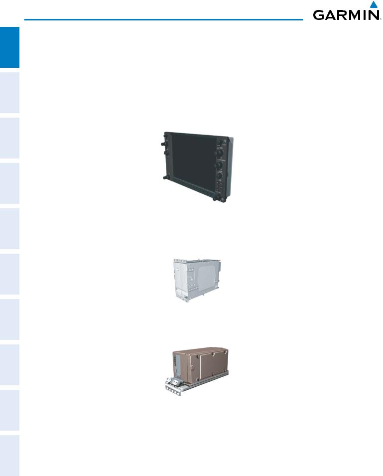
ADDITIONAL HAZARD FLIGHT AUDIO PANEL FLIGHT SYSTEM INDEX APPENDICES FEATURES AFCS AVOIDANCE MANAGEMENT & CNS EIS INSTRUMENTS OVERVIEW
SYSTEM OVERVIEW
1.2 LINE REPLACEABLE UNITS (LRU)
•GDU 1040/1044B – The GDU 1044B features a 10.4-inch LCD display with 1024 x 768 resolution. The left display is configured as a PFD and the right display is configured as an MFD. Both GDU 1044Bs link and display all functions of the G1000 system during flight. The displays communicate with each other through a High-Speed Data Bus (HSDB) Ethernet connection. Each display is also paired via an Ethernet connection with a GIA 63 or 63W Integrated Avionics Unit. Systems that do not use the GFC 700 Automatic Flight Control System use the GDU 1040, which employs the same features as the GDU 1044B without the controls for the Garmin GFC 700 Automatic Flight Control System (AFCS).
•GIA 63/63W (2) – Functions as the main communication hub, linking all LRUs with the PFD. Each GIA 63/63W contains a GPS receiver, VHF COM/NAV/GS receivers, a flight director (FD) and system integration microprocessors. The GIA 63W contains a GPS SBAS receiver. Each GIA is paired with a respective GDU 1040/1044B display through Ethernet. The GIAs are not paired together and do not communicate with each other directly.
•GDC 74A (1) – Processes data from the pitot/static system as well as the OAT probe. This unit provides pressure altitude, airspeed, vertical speed and OAT information to the G1000 system, and it communicates with the GIA 63/63W, GDU 1040/1044B, and GRS 77, using an ARINC 429 digital interface. The GDC 74A also interfaces directly with the GTP 59.
|
2 |
Garmin G1000 Pilot’s Guide for Cessna Nav III |
190-00498-07 Rev. A |

SYSTEM OVERVIEW
|
• GEA 71 (1) – Receives and processes signals from the engine and airframe sensors. This unit communicates |
SYSTEM OVERVIEW |
|
|
with both GIA 63/63Ws using an RS-485 digital interface. |
||
|
FLIGHT INSTRUMENTS |
||
|
• GRS 77 (1) – Provides aircraft attitude and heading information via ARINC 429 to both the GDU 1040/1044B |
||
|
and the GIA 63/63W. The GRS 77 contains advanced sensors (including accelerometers and rate sensors) and |
EIS |
|
|
interfaces with the on-side GMU 44 to obtain magnetic field information, with the GDC 74A to obtain air data, |
||
|
and with both GIAs to obtain GPS information. AHRS modes of operation are discussed later in this document. |
||
|
PANEL AUDIO CNS & |
||
|
• GMU 44 (1) – Measures local magnetic field. Data is sent to the GRS 77 for processing to determine aircraft |
FLIGHT MANAGEMENT |
|
|
magnetic heading. This unit receives power directly from the GRS 77 and communicates with the GRS 77 |
||
|
using an RS-485 digital interface. |
||
|
• GMA 1347 – The GMA 1347 Audio Panel integrates NAV/COM digital audio, intercom system and marker |
HAZARD AVOIDANCE |
|
|
beacon controls. The GMA 1347 also controls manual display reversionary mode (red DISPLAY BACKUP |
||
|
button) and is installed between the MFD and the PFD. The GMA 1347 communicates with both GIA 63/ |
||
|
63Ws using an RS-232 digital interface. |
AFCS |
|
|
ADDITIONAL FEATURES |
||
|
• GTX 33 (1) – The GTX 33 is a solid-state, Mode-S transponder that provides Modes A, C and S operation. The |
APPENDICES |
|
|
GTX 33 is controlled through the PFD and communicates with both GIA 63/63Ws through an RS-232 digital |
||
|
interface. |
||
|
INDEX |
|
190-00498-07 Rev. A |
Garmin G1000 Pilot’s Guide for Cessna Nav III |
3 |
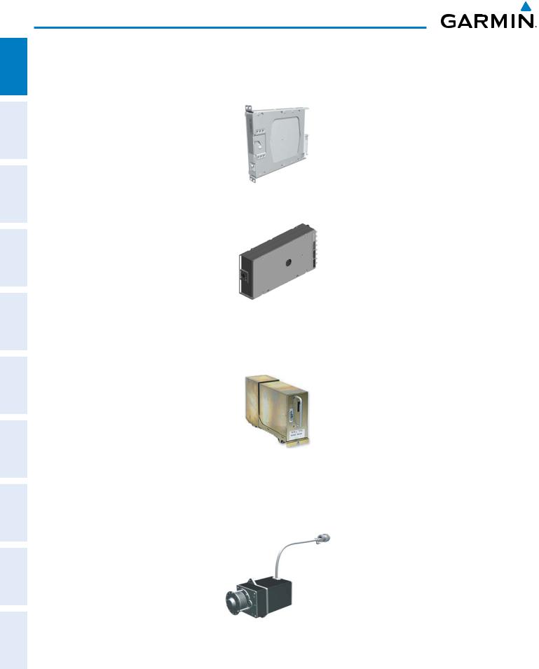
SYSTEM OVERVIEW
ADDITIONAL HAZARD FLIGHT AUDIO PANEL FLIGHT SYSTEM INDEX APPENDICES FEATURES AFCS AVOIDANCE MANAGEMENT & CNS EIS INSTRUMENTS OVERVIEW
•GDL 69A (1) – A satellite radio receiver that provides real-time weather information to the G1000 MFD (and, indirectly, to the inset map of the PFD) as well as digital audio entertainment. The GDL 69A communicates with the MFD via HSDB connection. A subscription to the SiriusXM Satellite Radio service is required to enable the GDL 69A capability.
•GTS 800 – The GTS 800 Traffic Advisory System (TAS) uses active interrogations of Mode S and Mode C transponders to provide Traffic Advisories to the pilot independent of the air traffic control system.
•GDL 90 (1) – A digital data link transceiver designed to transmit, receive and decode ADS-B traffic information, as well as FIS-B weather information. It broadcasts aircraft position, velocity, projected track, altitude, and flight identification to other equipped aircraft in the vicinity, as well as to FAA ground stations. The GDL 90 receives FIS-B weather information which is displayed on the MFD as NEXRAD radar and METARs.
•GSA 81 (3), and GSM 85 (3) – The GSA 81 servos are used for the automatic control of roll, pitch, and pitch trim. These units interface with each GIA 63/63W.
The GSM 85 servo gearbox is responsible for transferring the output torque of the GSA 81 servo actuator to the mechanical flight-control surface linkage.
|
4 |
Garmin G1000 Pilot’s Guide for Cessna Nav III |
190-00498-07 Rev. A |
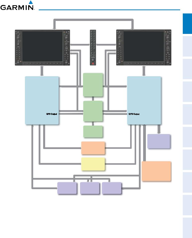
SYSTEM OVERVIEW
|
PFD |
MFD |
||
|
GDU 1040 or |
GMA 1347 |
GDU 1040 or |
|
|
GDU 1044B* |
Audio Panel |
GDU 1044B* |
|
|
Reversionary |
Reversionary |
||
|
Control |
Control |
GDC 74A
Air Data
Computer
|
No. 1 GIA 63/63W |
OAT |
No. 2 GIA 63/63W |
|
|
Integrated Avionics Unit |
Airspeed |
Integrated Avionics Unit |
|
|
Altitude |
|||
|
System Inegration Processors |
Vertical Speed |
System Integration Processors |
|
|
I/O Processors |
I/O Processors |
||
|
VHF COM |
VHF COM |
||
|
VHF NAV/LOC |
GRS 77 |
VHF NAV/LOC |
|
|
GPS/WAAS |
GPS/WAAS |
||
|
Glideslope |
AHRS |
Glideslope |
|
|
GFC 700 Flight Director |
|||
|
(172S, 182, & 206) |
Attitude |
||
|
GPS Output |
GPS Output |
||
|
Rate of Turn |
|||
|
Slip/Skid |
GMU 44
Magnetometer
Heading
GTX 33
Transponder
GEA 71
 Engine/Airframe
Unit
|
GSA 81 |
GSA 81 |
GSA 81 |
|
Pitch Servo |
Pitch Trim |
Roll Servo |
|
Autopilot Calculations |
Autopilot Calculations |
Autopilot Calculations |
|
(172S/TD,182 & 206) |
(172S/TD,182 & 206) |
(172S/TD,182 & 206) |
Honeywell
KAP 140
Autopilot
GTS 800
TAS
or
GDL 90
Data Link
ADS-B Traffic Data
*The GDU 1040 is available in systems not using the GFC 700 Automatic Flight Control System.
The GDU 1044B is available in systems using the Garmin GFC 700 Automatic Flight Control System.
Figure 1-1 Basic G1000 System
INDEX APPENDICES ADDITIONALFEATURES AFCS AVOIDANCEHAZARD MANAGEMENTFLIGHT PANELCNSAUDIO& EIS INSTRUMENTSFLIGHT OVERVIEWSYSTEM
|
190-00498-07 Rev. A |
Garmin G1000 Pilot’s Guide for Cessna Nav III |
5 |
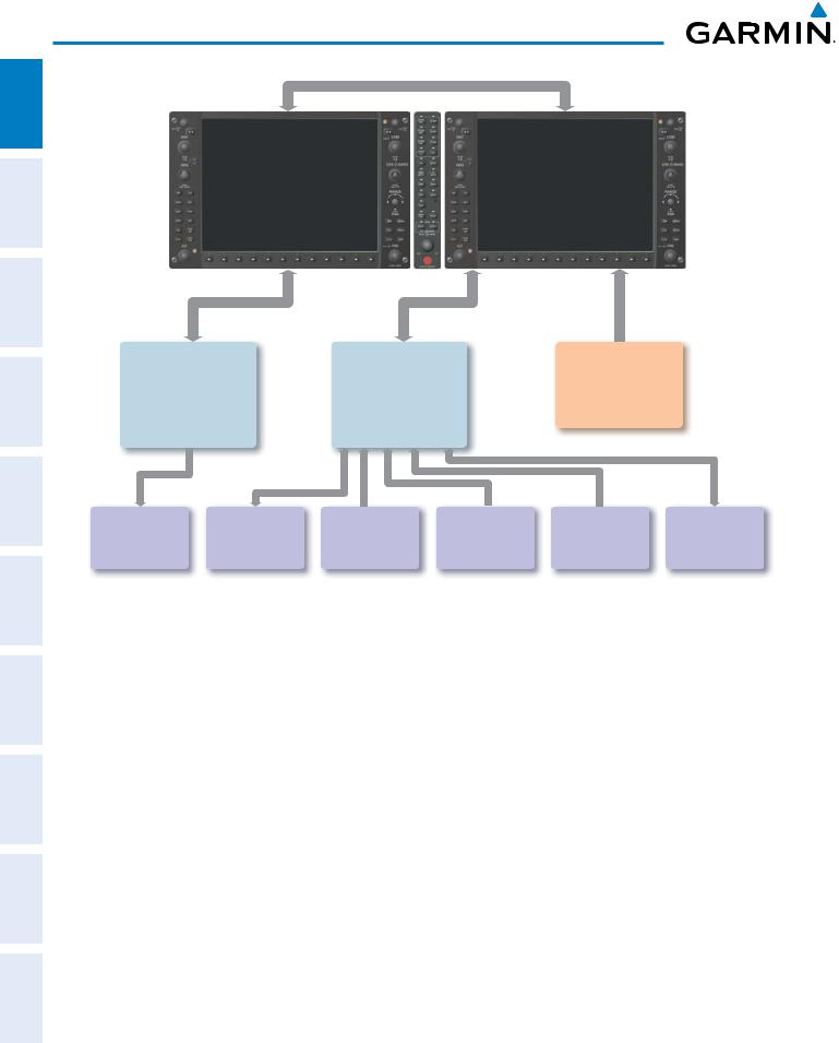
SYSTEM OVERVIEW
ADDITIONAL HAZARD FLIGHT AUDIO PANEL FLIGHT SYSTEM INDEX APPENDICES FEATURES AFCS AVOIDANCE MANAGEMENT & CNS EIS INSTRUMENTS OVERVIEW
|
No. 1 GIA 63/63W |
No. 2 GIA 63/63W |
||
|
Integrated Avionics Unit |
Integrated Avionics Unit |
GDL 69/69A |
|
|
System Integration Processors |
System Integration Processors |
Data Link |
|
|
I/O Processors |
I/O Processors |
||
|
Weather Data |
|||
|
VHF COM |
VHF COM |
||
|
Digital Audio Entertainment |
|||
|
VHF NAV/LOC |
VHF NAV/LOC |
||
|
GPS |
GPS |
||
|
Glideslope |
Glideslope |
||
|
GFC 700 Flight Director |
|
ELT |
L3 |
Honeywell |
Honeywell |
CO Guardian |
Honeywell |
|
|
Stormscope |
||||||
|
Emergency Locator |
KR 87 |
KN 63 |
Carbon Monoxide |
KTA 870 |
||
|
Lightning Strike and |
Traffic Avoidance |
|||||
|
Transmitter |
ADF Receiver |
DME |
Detection |
|||
|
Thunderstorm Detection |
System |
|||||
Figure 1-2 Additional Equipment Options
|
6 |
Garmin G1000 Pilot’s Guide for Cessna Nav III |
190-00498-07 Rev. A |
![]()
SYSTEM OVERVIEW
1.3 G1000 CONTROLS
NOTE: The Audio Panel (GMA 1347) and AFCS controls are described in the CNS & Audio Panel and AFCS sections respectively.
The G1000 system controls are located on the PFD and MFD bezels and audio panel. The controls for the PFD and MFD are discussed within the following pages of this section.
FLIGHT SYSTEM INSTRUMENTS OVERVIEW
PFD/MFD CONTROLS
|
1 |
2 |
3 |
4 |
5 |
6 |
7 |
8 |
9 |
|
17 |
||||
|
18 |
24 |
14 |
||
|
19 |
25 |
10 |
||
|
11 |
15 |
|||
|
20 |
26 |
12 |
16 |
|
|
21 |
27 |
|||
|
22 |
28 |
13 |
||
|
23 |
29 |
|||
|
GFC 700 AFCS Only |
Figure 1-3 |
PFD/MFD Controls |
INDEX APPENDICES ADDITIONAL AFCS HAZARD FLIGHT PANEL AUDIO EIS FEATURES AVOIDANCE MANAGEMENT CNS &
|
190-00498-07 Rev. A |
Garmin G1000 Pilot’s Guide for Cessna Nav III |
7 |

SYSTEM OVERVIEW
ADDITIONAL HAZARD FLIGHT AUDIO PANEL FLIGHT SYSTEM INDEX APPENDICES FEATURES AFCS AVOIDANCE MANAGEMENT & CNS EIS INSTRUMENTS OVERVIEW
PFD and MFD control functions are the same.
1NAV VOL/ID Knob – Controls the NAV audio level. Press to toggle the Morse code identifier ON and OFF. Volume level is shown in the field as a percentage.
2NAV Frequency Transfer Key – Transfers the standby and active NAV frequencies.
3Dual NAV Knob – Tunes the MHz (large knob) and kHz (small knob) standby frequencies for the NAV receiver. Press to toggle the tuning cursor (light blue box) between the NAV1 and NAV2 fields.
4Heading Knob – Turn to manually select a heading on the HSI. When pressed, it synchronizes the heading bug with the compass lubber line. Selected Heading provides the heading reference to the Flight Director while operating in Heading Select mode.
5Joystick – Changes the map range (distance top to bottom of map display) when rotated. Activates the map pointer when pressed.
6CRS/BARO Knob – The large knob sets the altimeter barometric pressure and the small knob adjusts the course. The course is only adjustable when the HSI is in VOR1, VOR2, or OBS/SUSP mode. Pressing this knob centers the CDI on the currently selected VOR. Selected Course provides course reference to the Flight Director when operating in Navigation and Approach modes.
7Dual COM Knob – Tunes the MHz (large knob) and kHz (small knob) standby frequencies for the COM transceiver. Pressing this knob toggles the tuning cursor (light blue box) between the COM1 and COM2 fields.
8COM Frequency Transfer Key – Transfers the standby and active COM frequencies. Pressing and holding this key for two seconds automatically tunes the emergency frequency (121.5 MHz) in the active frequency field.
9COM VOL/SQ Knob – Controls COM audio level. Audio volume level is shown in the field as a percentage. Pressing this knob turns the COM automatic squelch ON and OFF.
10Direct-to Key – Allows the user to enter a destination waypoint and establish a direct course to the selected destination (specified by the identifier, chosen from the active route, or taken from the map pointer position).
11FPL Key – Displays the active Flight Plan Page for creating and editing the active flight plan, or for accessing stored flight plans.
12CLR Key (DFLT MAP) – Erases information, cancels an entry, or removes page menus. To display the Navigation Map Page immediately, press and hold CLR (MFD only).
13Dual FMS Knob – Press to turn the selection cursor ON/OFF.
Data Entry: With the cursor ON, turn to enter data in the highlighted field (large knob moves cursor location; small knob selects character for highlighted cursor location). When the cursor is turned ON while viewing the Active Flight Plan Page, the cursor is placed on the line below the Data Insertion Pointer see Figure 1-4. The pointer indicates data entered at the cursor will be inserted above the line selected.
Scrolling: When a list of information is too long for the window/box, a scroll bar appears, indicating more items to view. With cursor ON, turn large knob to scroll through the list.
Page Selection: Turn knob on MFD to select the page to view (large knob selects a page group; small knob selects a specific page from the group)
14MENU Key – Displays a context-sensitive list of options. This list allows the user to access additional features, or to make setting changes that relate to certain pages.
|
8 |
Garmin G1000 Pilot’s Guide for Cessna Nav III |
190-00498-07 Rev. A |
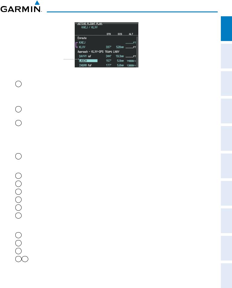
SYSTEM OVERVIEW
Data is Inserted Above the Cursor, Indicated by the Data Insertion Pointer
Figure 1-4 Data Insertion Pointer
15PROC Key – Selects approaches, departures and arrivals from the flight plan. If a flight plan is used, available procedures for the departure and/or arrival airport are automatically suggested. If a flight plan is not used, the desired airport and the desired procedure may be selected. This key selects IFR departure procedures (DPs), arrival procedures (STARs) and approaches (IAPs) from the database and loads them into the active flight plan.
16ENT Key – Accepts a menu selection or data entry. This key is used to approve an operation or complete data entry. It is also used to confirm selections and information entries.
17Dual ALT Knob – Sets the selected altitude in the box located above the Altimeter. The large knob selects the thousands (500m for metric), while the small knob selects the hundreds (50m for metric). Altitude Select is used by the Automatic Flight Control System in certain modes, in addition to the standard G1000 Altitude Alerter function.
The following are only available with the GFC 700 AFCS.
18AP Key – Engages/disengages the autopilot and flight director. Pressing the AP Key activates the flight director and engages the autopilot in the default pitch axis and roll axis modes. Pressing the AP Key again disengages the autopilot and deactivates the flight director.
19HDG Key – Selects/deselects Heading Select Mode.
20NAV Key – Selects/deselects Navigation Mode.
21APR Key – Selects/deselects Approach Mode.
22VS Key – Selects/deselects Vertical Speed Mode.
23 FLC Key – Selects/deselects Flight Level Change Mode.
24FD Key – Activates/deactivates the flight director only. Pressing the FD Key turns on the flight director in the default pitch axis and roll axis modes. Pressing the FD Key again deactivates the flight director and removes the command bars, unless the autopilot is engaged. If the autopilot is engaged, the FD Key is disabled.
25ALT Key – Selects/deselects Altitude Hold Mode.
26VNV Key – Selects/deselects Vertical Navigation Mode.
27BC Key – Selects/deselects Back Course Mode.
2829 NOSE UP/NOSE DN Keys – Controls the active pitch reference for the Pitch Hold, Vertical Speed, and Flight Level Change modes.
INDEX APPENDICES ADDITIONALFEATURES AFCS AVOIDANCEHAZARD MANAGEMENTFLIGHT PANELCNSAUDIO& EIS INSTRUMENTSFLIGHT OVERVIEWSYSTEM
|
190-00498-07 Rev. A |
Garmin G1000 Pilot’s Guide for Cessna Nav III |
9 |
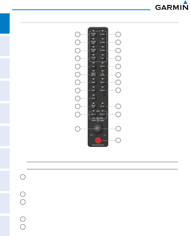
ADDITIONAL HAZARD FLIGHT AUDIO PANEL FLIGHT SYSTEM INDEX APPENDICES FEATURES AFCS AVOIDANCE MANAGEMENT & CNS EIS INSTRUMENTS OVERVIEW
SYSTEM OVERVIEW
AUDIO PANEL CONTROLS
|
1 |
2 |
|
3 |
4 |
|
5 |
6 |
|
7 |
8 |
|
9 |
10 |
|
11 |
12 |
|
13 |
14 |
|
15 |
16 |
|
17 |
|
|
18 |
19 |
|
20 |
21 |
|
22 |
23 |
|
24 |
Figure 1-5 Audio Panel Controls (GMA 1347)
 NOTE: When a key is selected, a triangular annunciator above the key is illuminated.
1COM1 MIC – Selects the #1 transmitter for transmitting. COM1 receive is simultaneously selected when this key is pressed allowing received audio from the #1 COM receiver to be heard. COM2 receiver audio can be added by pressing the COM2 Key.
2COM1 – When selected, audio from the #1 COM receiver can be heard.
3COM2 MIC – Selects the #2 transmitter for transmitting. COM2 is simultaneously selected when this key is pressed allowing received audio from the #2 COM receiver to be heard. COM2 can be deselected by pressing the COM2 Key, or COM1 can be added by pressing the COM1 Key.
4COM2 – When selected, audio from the #2 COM receiver can be heard.
5COM3 MIC – Not used on Cessna Nav III aircraft.
|
10 |
Garmin G1000 Pilot’s Guide for Cessna Nav III |
190-00498-07 Rev. A |

SYSTEM OVERVIEW
|
6 |
COM3 – Not used on Cessna Nav III aircraft. |
SYSTEM OVERVIEW |
|
|
7 |
COM 1/2 – Split COM is disabled on Cessna Nav III aircraft. |
||
|
8 |
TEL – Not used on Cessna Nav III aircraft. |
||
|
FLIGHT INSTRUMENTS |
|||
|
9 |
PA – Selects the Passenger Address system. The selected COM transmitter is deselected when the PA Key |
||
is pressed. The Passenger Address system is disabled on the Cessna 172R/S.
10SPKR – Selects and deselects the cabin speaker. COM and NAV receiver audio can be heard on the speaker.
11MKR/MUTE – Mutes the currently received marker beacon receiver audio. Unmutes when new marker beacon audio is received. Also, stops play of the clearance recorder.
12HI SENS – Press to increase marker beacon receiver sensitivity. Press again to return to normal.
13DME – Pressing turns DME audio on or off.
14NAV1 – When selected, audio from the #1 NAV receiver can be heard.
15ADF – Pressing turns on or off the audio from the ADF receiver.
16NAV2 – When selected, audio from the #2 NAV receiver can be heard.
17AUX – Not used on Cessna Nav III aircraft.
18MAN SQ – Press to enable manual squelch for the intercom. When active, press the PILOT Knob to illuminate ‘SQ’. Turn the PILOT/PASS Knobs to adjust squelch.
19PLAY – Press once to play the last recorded audio. Pressing the PLAY Key during play begins playing the previously recorded memory block. Each subsequent press of the PLAY Key begins playing the next previously recorded block. Press the MKR/MUTE Key to stop play.
20PILOT – Pressing selects the pilot intercom isolation. Press again to deselect pilot isolation.
21COPLT – Pressing selects the copilot intercom isolation. Press again to deselect copilot isolation.
22PILOT Knob – Press to switch between volume and squelch control as indicated by the ‘VOL’ or ‘SQ’ being illuminated. Turn to adjust intercom volume or squelch. The MAN SQ Key must be selected to allow squelch adjustment.
23PASS Knob – Turn to adjust Copilot/Passenger intercom volume or squelch. The MAN SQ Key must be selected to allow squelch adjustment.
24Reversionary Mode Button – Pressing manually selects Reversionary Mode.
INDEX APPENDICES ADDITIONAL AFCS HAZARD FLIGHT PANEL AUDIO EIS FEATURES AVOIDANCE MANAGEMENT CNS &
|
190-00498-07 Rev. A |
Garmin G1000 Pilot’s Guide for Cessna Nav III |
11 |

ADDITIONAL HAZARD FLIGHT AUDIO PANEL FLIGHT SYSTEM FEATURES AFCS AVOIDANCE MANAGEMENT & CNS EIS INSTRUMENTS OVERVIEW
SYSTEM OVERVIEW
1.4 SECURE DIGITAL (SD) CARDS
 NOTE: Ensure the G1000 System is powered off before inserting an SD card.
 NOTE: Refer to Appendix B for instructions on loading database updates.
The PFD and MFD data card slots use Secure Digital (SD) cards and are located on the upper right side of the display bezels. SD cards are used for storing the various databases and system software updates. Each display bezel is equipped with two SD card slots. The top slot is used for importing and exporting flight plans, Flight Data Logging, and loading navigation database updates. The bottom slot of each display contains a Garmin Supplemental Data Card which is used for storing the various databases.
Not all SD cards are compatible with the G1000. Use only SD cards supplied by Garmin or the aircraft manufacturer.
Installing an SD card:
1)Insert the SD card in the SD card slot, pushing the card in until the spring latch engages. The front of the card should remain flush with the face of the display bezel.
2)To eject the card, gently press on the SD card to release the spring latch.
SD Card Slots
INDEX APPENDICES
Figure 1-6 Display Bezel SD Card Slots
|
12 |
Garmin G1000 Pilot’s Guide for Cessna Nav III |
190-00498-07 Rev. A |

SYSTEM OVERVIEW
1.5 SYSTEM POWER-UP
NOTE: See the Aircraft Flight Manual (AFM) for specific procedures concerning avionics power application and emergency power supply operation.
 NOTE: Refer to Appendix A for system-specific annunciations and alerts.
The G1000 System is integrated with the aircraft electrical system and receives power directly from electrical busses. The G1000 PFD, MFD, and supporting sub-systems include both power-on and continuous built-in test features that exercise the processor, RAM, ROM, external inputs, and outputs to provide safe operation.
During system initialization, test annunciations are displayed, as shown in Figure 1-7. All system annunciations should disappear typically within the first minute of power-up. Upon power-up, key annunciator lights also become momentarily illuminated on the Audio Panel.
On the PFD, the AHRS begins to initialize and displays “AHRS ALIGN: Keep Wings Level”. The AHRS should display valid attitude and heading fields typically within the first minute of power-up. The AHRS can align itself both while taxiing and during level flight.
When the MFD powers up, the power-up screen (Figure 1-8) displays the following information:
|
• System version |
• Obstacle database name and version |
|
• Copyright |
• Navigation database name, version, and effective dates |
|
• Land database name and version |
• Airport Directory name, version and effective dates |
|
• Safe Taxi database information |
• FliteCharts/ChartView database information |
|
• Terrain database name and version |
Current database information includes database type, cycle number, or valid operating dates. Review the listed information for currency (to ensure that no databases have expired).
Pressing the ENT Key (or right-most softkey) acknowledges this information, and the Navigation Map Page is displayed upon pressing the key a second time. When the system has acquired a sufficient number of satellites to determine a position, the aircraft’s current position is shown on the Navigation Map Page.
APPENDICES ADDITIONALFEATURES AFCS AVOIDANCEHAZARD MANAGEMENTFLIGHT PANELCNSAUDIO& EIS INSTRUMENTSFLIGHT OVERVIEWSYSTEM
|
Figure 1-7 PFD Initialization |
Figure 1-8 MFD Power-Up Screen (172R shown) |
INDEX
|
190-00498-07 Rev. A |
Garmin G1000 Pilot’s Guide for Cessna Nav III |
13 |
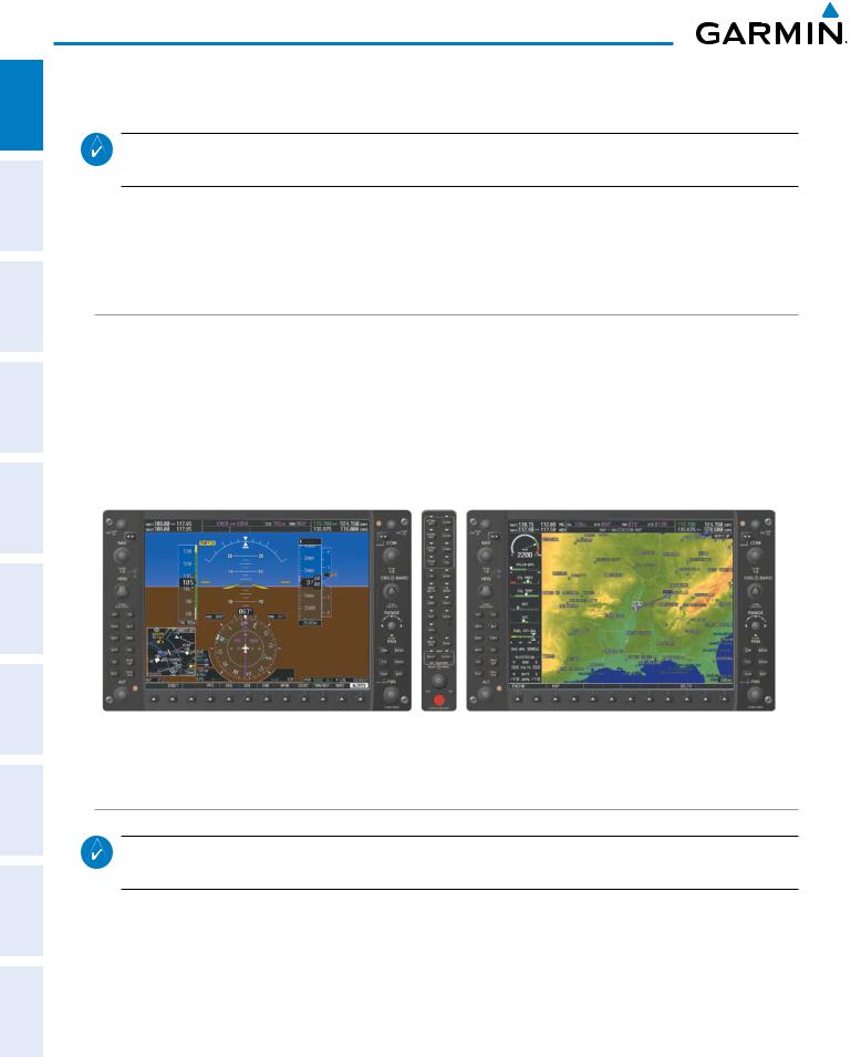
ADDITIONAL HAZARD FLIGHT AUDIO PANEL FLIGHT SYSTEM INDEX APPENDICES FEATURES AFCS AVOIDANCE MANAGEMENT & CNS EIS INSTRUMENTS OVERVIEW
SYSTEM OVERVIEW
1.6 SYSTEM OPERATION
NOTE: In normal operating mode, backlighting can only be adjusted from the PFD. In reversionary mode, it can be adjusted from the remaining display.
The displays are connected together via a single Ethernet bus for high-speed communication. Each IAU is connected to a single display, as shown in Figure 1-1. This allows the units to share information, enabling true system integration.. This section discusses normal and reversionary G1000 display operation, as well as the various AHRS modes and G1000 System Annunciations.
NORMAL DISPLAY OPERATION
In normal operating mode, the PFD presents graphical flight instrumentation (attitude, heading, airspeed, altitude, vertical speed), replacing the traditional flight instrument cluster (see the Flight Instruments Section for more information).
The MFD normally displays a full-color moving map with navigation information (see the Flight Management Section), while the left portion of the MFD is dedicated to the Engine Indication System (EIS; see the EIS Section).
Both displays offer control for COM and NAV frequency selection.
Figure 1-9 Normal Mode
REVERSIONARY DISPLAY OPERATION
NOTE: The G1000 System alerts the pilot when backup paths are utilized by the LRUs. Refer to Appendix A for further information regarding system-specific alerts.
In the event of a display failure, the G1000 System automatically switches to reversionary (backup) mode. In reversionary mode, all important flight information is presented on the remaining display in the same format as in normal operating mode.
|
14 |
Garmin G1000 Pilot’s Guide for Cessna Nav III |
190-00498-07 Rev. A |
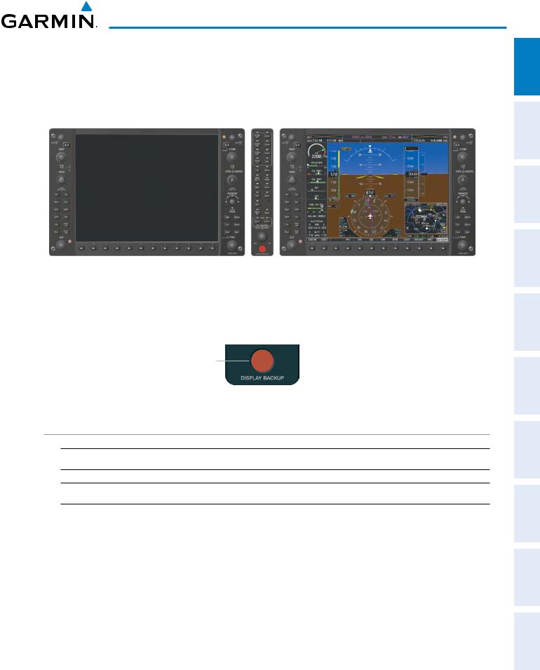
SYSTEM OVERVIEW
If a display fails, the appropriate IAU Ethernet interface to the display is cut off. Thus, the IAU can no longer communicate with the remaining display (refer to Figure 1-1), and the NAV and COM functions provided to the failed display by the IAU are flagged as invalid on the remaining display. The system reverts to backup paths for the AHRS, ADC, Engine/Airframe Unit, and Transponder, as required. The change to backup paths is completely automated for all LRUs and no pilot action is required.
Figure 1-10 Reversionary Mode (Failed PFD)
If the system fails to detect a display problem, reversionary mode may be manually activated by pressing the Audio Panel’s red DISPLAY BACKUP button (refer to the Audio Panel and CNS Section for further details). Pressing this button again deactivates reversionary mode.
Pressing the DISPLAY BACKUP button activates/deactivates reversionary mode
Figure 1-11 DISPLAY BACKUP Button
AHRS OPERATION
 NOTE: Refer to Appendix A for specific AHRS alert information.
 NOTE: Aggressive maneuvering while AHRS is not operating normally may degrade AHRS accuracy.
The Attitude and Heading Reference System (AHRS) performs attitude, heading, and vertical acceleration calculations for the G1000 System, utilizing GPS, magnetometer, and air data in addition to information from its internal sensors. Attitude and heading information are updated on the PFD while the AHRS receives appropriate combinations of information from the external sensor inputs.
Loss of GPS, magnetometer, or air data inputs is communicated to the pilot by message advisory alerts. Any failure of the internal AHRS inertial sensors results in loss of attitude and heading information (indicated by red ‘X’ flags over the corresponding flight instruments).
INDEX APPENDICES ADDITIONALFEATURES AFCS AVOIDANCEHAZARD MANAGEMENTFLIGHT PANELCNSAUDIO& EIS INSTRUMENTSFLIGHT OVERVIEWSYSTEM
|
190-00498-07 Rev. A |
Garmin G1000 Pilot’s Guide for Cessna Nav III |
15 |
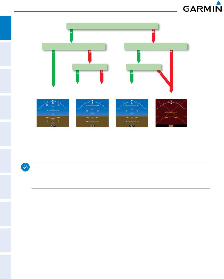
SYSTEM OVERVIEW
ADDITIONAL HAZARD FLIGHT AUDIO PANEL FLIGHT SYSTEM INDEX APPENDICES FEATURES AFCS AVOIDANCE MANAGEMENT & CNS EIS INSTRUMENTS OVERVIEW
GPS Data
|
availab |
unavailab |
||||
|
Magnetometer Data |
Magnetometer Data |
||||
|
availab |
unavailab |
availab |
unavailab |
||
|
Air Data |
Air Data |
||||
|
availab |
unavailab |
availab |
una |
||
|
v |
|||||
|
ailab |
|||||
|
le |
|||||
|
AHRS Normal |
AHRS no- |
AHRS no-Mag/ |
AHRS |
||
|
Mag Mode |
no-Air Mode |
no-GPS |
|||
|
Operation |
Attitude/Heading Invalid |
||||
|
Heading Invalid |
Mode |
||||
Figure 1-12 AHRS Operation
GPS INPUT FAILURE
NOTE: In-flight initialization of AHRS, when operating without any valid source of GPS data and at true air speed values greater than approximately 200 knots, is not guaranteed. Under these rare conditions, it is possible for in-flight AHRS initialization to take an indefinite amount of time which would result in an extended period of time where valid AHRS outputs are unavailable.
Two GPS inputs are provided to the AHRS. If GPS information from one of the inputs fails, the AHRS uses the remaining GPS input and an alert message is issued to inform the pilot. If both GPS inputs fail, the AHRS can continue to provide attitude and heading information to the PFD as long as magnetometer and airspeed data are available and valid.
MAGNETOMETER FAILURE
If the magnetometer input fails, the AHRS continues to output valid attitude information; however, the heading output on the PFD is flagged as invalid with a red ‘X’.
AIR DATA INPUT FAILURE
Failure of the air data input has no affect on the AHRS output while AHRS is receiving valid GPS information. Invalid/unavailable airspeed data in addition to GPS failure results in loss of all attitude and heading information.
|
16 |
Garmin G1000 Pilot’s Guide for Cessna Nav III |
190-00498-07 Rev. A |
![]()
SYSTEM OVERVIEW
G1000 SYSTEM ANNUNCIATIONS
NOTE: For a detailed description of all annunciations and alerts, refer to Appendix A. Refer to the Pilot’s Operating Handbook (POH) for additional information regarding pilot responses to these annunciations.
When an LRU or an LRU function fails, a large red “X” is typically displayed on windows associated with the failed data (Figure 1-13 displays all possible flags and responsible LRUs). Upon G1000 power-up, certain windows remain invalid as equipment begins to initialize. All windows should be operational within one minute of power-up. If any window remains flagged, the G1000 system should be serviced by a Garminauthorized repair facility.
EIS FLIGHT SYSTEM INSTRUMENTS OVERVIEW
|
GIA 63/W |
GIA 63/W |
|||||||||||||||||||
|
Integrated |
Integrated |
|||||||||||||||||||
|
Avionics Units |
Avionics Units |
|||||||||||||||||||
|
GDC 74A Air |
||||||||||||||||||||
|
Data Computer |
||||||||||||||||||||
|
Database |
||||||||||||||||||||
|
GEA 71 Engine |
Mismatch in PFD |
|||||||||||||||||||
|
and MFD |
||||||||||||||||||||
|
Airframe Unit |
||||||||||||||||||||
|
OR |
||||||||||||||||||||
|
GIA 63/W |
GRS 77 AHRS |
|||||||||||||||||||
|
Integrated |
||||||||||||||||||||
|
OR |
||||||||||||||||||||
|
Avionics Unit |
||||||||||||||||||||
|
GMU 44 |
||||||||||||||||||||
|
Magnetometer |
||||||||||||||||||||
|
GIA 63/W Integrated |
||||||||||||||||||||
|
Avionics Units |
||||||||||||||||||||
|
GDC 74A Air |
GTX 33 Transponder |
|||||||||||||||||||
|
OR |
||||||||||||||||||||
|
Data Computer |
||||||||||||||||||||
|
GIA 63/W Integrated |
||||||||||||||||||||
|
Figure 1-13 |
G1000 System Failure Annunciations |
Avionics Units |
||||||||||||||||||
SOFTKEY FUNCTION
The softkeys are located along the bottoms of the displays. The softkeys shown depend on the softkey level or page being displayed. The bezel keys below the softkeys can be used to select the appropriate softkey. When a softkey is selected, its color changes to black text on gray background and remains this way until it is turned off, at which time it reverts to white text on black background.
Softkey
On
Softkey Names
Bezel-Mounted (Displayed)
Softkeys (Press)
Figure 1-14 Softkeys (Second-Level PFD Configuration)
INDEX APPENDICES ADDITIONALFEATURES AFCS AVOIDANCEHAZARD MANAGEMENTFLIGHT PANELCNSAUDIO&
|
190-00498-07 Rev. A |
Garmin G1000 Pilot’s Guide for Cessna Nav III |
17 |

ADDITIONAL HAZARD FLIGHT AUDIO PANEL FLIGHT SYSTEM INDEX APPENDICES FEATURES AFCS AVOIDANCE MANAGEMENT & CNS EIS INSTRUMENTS OVERVIEW
SYSTEM OVERVIEW
PFD SOFTKEYS
The CDI, IDENT, TMR/REF, NRST, and ALERTS softkeys undergo a momentary change to black text on gray background and automatically switch back to white text on black background when selected.
The PFD softkeys provide control over flight management functions, including GPS, NAV, terrain, traffic, and lightning (optional). Each softkey sublevel has a BACK Softkey which can be selected to return to the previous level. The ALERTS Softkey is visible at all softkey levels (label changes if messages are issued).
|
INSET |
Displays Inset Map in PFD lower left corner |
||
|
OFF |
Removes Inset Map |
||
|
DCLTR (3) |
Selects desired amount of map detail; cycles through declutter levels: |
||
|
DCLTR (No Declutter): All map features visible |
|||
|
DCLTR-1: Declutters land data |
|||
|
DCLTR-2: Declutters land and SUA data |
|||
|
DCLTR-3: Removes everything except for the active flight plan |
|||
|
WX LGND |
Displays icon and age on the Inset Map for the selected weather products |
||
|
(optional) |
|||
|
TRAFFIC |
Cycles through traffic display options: |
||
|
TRFC-1: Traffic displayed on inset map |
|||
|
TRFC-2: Traffic Map Page is displayed in the inset map window |
|||
|
TOPO |
Displays topographical data (e.g., coastlines, terrain, rivers, lakes) and elevation |
||
|
scale on Inset Map |
|||
|
TERRAIN |
Displays terrain information on Inset Map |
||
|
STRMSCP |
Displays Stormscope® information on Inset Map |
||
|
NEXRAD |
Displays NEXRAD weather and coverage information on Inset Map (optional) |
||
|
or |
|||
|
PRECIP |
Displays GFDS or FIS-B precipitation on Inset Map (optional) |
||
|
XM LTNG |
Displays XM WX lightning information on Inset Map (optional) |
||
|
or |
Displays GFDS Worldwide Weather lightning information on Inset Map |
||
|
DL LTNG |
(optional) |
||
|
METAR |
Displays METAR flags on airport symbols shown on the Inset Map |
||
|
(optional) |
|||
|
PFD |
Displays second-level softkeys for additional PFD configurations |
||
|
SYN VIS |
Displays the softkeys for enabling or disabling Synthetic Vision |
||
|
features |
|||
|
PATHWAY |
Displays rectangular boxes representing the horizontal and vertical |
||
|
flight path of the active flight plan |
|||
|
SYN TERR |
Enables synthetic terrain depiction |
||
|
HRZN HDG |
Displays compass heading along the Zero-Pitch line |
||
|
APTSIGNS |
Displays position markers for airports within approximately 15 nm of |
||
|
the current aircraft position. Airport identifiers are displayed when |
|||
|
the airport is within approximately 9 nm. |
|||
|
DFLTS |
Resets PFD to default settings, including changing units to standard |
||
|
18 |
Garmin G1000 Pilot’s Guide for Cessna Nav III |
190-00498-07 Rev. A |

|
SYSTEM OVERVIEW |
|||||||
|
SYSTEM OVERVIEW |
|||||||
|
WIND |
Displays softkeys to select wind data parameters |
||||||
|
OPTN 1 |
Wind direction arrows with headwind and crosswind components |
||||||
|
OPTN 2 |
Wind direction arrow and speed |
||||||
|
OPTN 3 |
Wind direction arrow with direction and speed |
FLIGHT INSTRUMENTS |
|||||
|
OFF |
Information not displayed |
||||||
|
DME |
Displays the DME Information Window |
||||||
|
BRG1 |
Cycles the Bearing 1 Information Window through NAV1, GPS/ waypoint |
||||||
|
identifier and GPS-derived distance information, and ADF/frequency |
|||||||
|
HSI FRMT |
Provides access to the HSI formatting softkeys |
EIS |
|||||
|
360 HSI |
Displays the HSI in a 360 degree view |
||||||
|
ARC HSI |
Displays the HSI as an arc |
||||||
|
PANELAUDIO CNS& |
|||||||
|
BRG2 |
Cycles the Bearing 2 Information Window through NAV2 or GPS waypoint |
||||||
|
identifier and GPS-derived distance information, and ADF/frequency. |
|||||||
|
ALT UNIT |
Displays softkeys for setting the altimeter and BARO settings to metric |
||||||
|
units |
|||||||
|
METERS |
When enabled, displays altimeter in meters |
FLIGHT MANAGEMENT |
|||||
|
IN |
Press to display the BARO setting as inches of mercury |
||||||
|
HPA |
Press to display the BARO setting as hectopacals |
||||||
|
STD BARO |
Sets barometric pressure to 29.92 in Hg (1013 hPa if METRIC Softkey is selected) |
||||||
|
OBS |
Selects OBS mode on the CDI when navigating by GPS (only available with |
HAZARD AVOIDANCE |
|||||
|
active leg) |
|||||||
|
CDI |
Cycles through GPS, VOR1, and VOR2 navigation modes on the CDI |
||||||
|
DME |
Displays the DME Tuning Window, allowing selection of the DME |
||||||
|
XPDR |
Displays transponder mode selection softkeys |
||||||
|
STBY |
Selects standby mode (transponder does not reply to any interrogations) |
AFCS |
|||||
|
ON |
Selects Mode A (transponder replies to interrogations) |
||||||
|
ALT |
Selects Mode C – altitude reporting mode (transponder replies to identification |
||||||
|
and altitude interrogations) |
|||||||
|
GND |
Allows manual selection of ground mode in certain conditions |
ADDITIONAL FEATURES |
|||||
|
VFR |
Automatically enters the VFR code (1200 in the U.S.A. only) |
||||||
|
CODE |
Displays transponder code selection softkeys 0-7 |
||||||
|
0 — 7 |
Use numbers to enter code |
||||||
|
IDENT |
Activates the Special Position Identification (SPI) pulse for 18 seconds, |
APPENDICES |
|||||
|
identifying the transponder return on the ATC screen |
|||||||
|
BKSP |
Removes numbers entered, one at a time |
||||||
|
IDENT |
Activates the Special Position Identification (SPI) pulse for 18 seconds, |
||||||
|
identifying the transponder return on the ATC screen |
|||||||
|
TMR/REF |
Displays Timer/References Window |
INDEX |
|||||
|
NRST |
Displays Nearest Airports Window |
||||||
|
ALERTS |
Displays Alerts Window |
||||||
|
190-00498-07 Rev. A |
Garmin G1000 Pilot’s Guide for Cessna Nav III |
19 |

SYSTEM OVERVIEW
ADDITIONAL HAZARD FLIGHT AUDIO PANEL FLIGHT SYSTEM INDEX APPENDICES FEATURES AFCS AVOIDANCE MANAGEMENT & CNS EIS INSTRUMENTS OVERVIEW
Figure 1-15 Top Level PFD Softkeys
|
(optional) |
||||||||||||||||||||||||||||||||||||||||||||||
|
DME |
ALERTS |
|||||||||||||||||||||||||||||||||||||||||||||
|
(optional) |
(optional) |
|||||||||||||||||||||||||||||||||||||||||||||
|
(optional) |
(optional) |
PRECIP |
DL LTNG |
(optional) |
||||||||||||||||||||||||||||||||||||||||||
|
or |
or |
|||||||||||||||||||||||||||||||||||||||||||||
|
WX LGND |
STRMSCP |
METAR |
ALERTS |
|||||||||||||||||||||||||||||||||||||||||||
|
TRFC-1 |
Press the BACK or OFF Softkey |
|||||||||||||||||||||||||||||||||||||||||||||
|
to return to the top-level softkeys. |
||||||||||||||||||||||||||||||||||||||||||||||
|
TRFC-2 |
||||||||||||||||||||||||||||||||||||||||||||||
Figure 1-16 INSET Softkeys
|
SYN VIS |
DME |
HSI FRMT |
ALT UNIT |
ALERTS |
||||||||||||||||||||||||
|
BRG1(NAV1) |
BRG2(NAV2) |
Press the BACK Softkey |
||||||||||||||||||||||||||
|
to return to the top-level softkeys |
||||||||||||||||||||||||||||
|
BRG1(GPS) |
BRG2(GPS) |
|||||||||||||||||||||||||||
|
BRG1(ADF) |
BRG2(ADF) |
||
|
BRG1(OFF) |
BRG2(OFF) |
||
|
360 HSI |
ARC HSI |
ALERTS |
|
|
ALERTS |
|||
|
METERS |
IN |
HPA |
ALERTS |

 PATHWAY
 SYN TERR
 HRZN HDG
 APTSIGNS


 ALERTS
Figure 1-17 PFD Configuration Softkeys
|
20 |
Garmin G1000 Pilot’s Guide for Cessna Nav III |
190-00498-07 Rev. A |

SYSTEM OVERVIEW
|
DME |
ALERTS |
||||||||||


 ALERTS
Press the BACK Softkey to return to the top-level softkeys.

 ALERTS
Press the BACK Softkey to return to the previous softkey level.
EIS FLIGHT SYSTEM INSTRUMENTS OVERVIEW
|
Figure 1-18 XPDR (Transponder) Softkeys |
||||
|
MFD SOFTKEYS |
||||
|
ENGINE |
Pressing this softkey makes available the LEAN |
|||
|
and SYSTEM Softkeys |
||||
|
LEAN |
Pressing makes available the CYL SLCT and |
|||
|
ASSIST Softkeys to facilitate engine leaning |
||||
|
CYL SLCT |
The Cylinder Select Softkey cycles through |
|||
|
selection of each cylinder indicated by changing |
||||
|
the cylinder display to light blue |
||||
|
ASSIST |
Pressing the ASSIST Softkey causes the first |
|||
|
cylinder that peaks to become highlighted and |
||||
|
information for that cylinder to be displayed |
||||
|
BACK |
Returns to the previous level softkeys |
|||
|
SYSTEM |
Press this softkey to make available the RST |
|||
|
FUEL and GAL REM Softkeys |
||||
|
RST FUEL |
Pressing the Rest Fuel Softkey resets fuel used and |
|||
|
gallons remaining to zero |
||||
|
GAL REM |
Press this softkey (Gallons Remaining) to display |
|||
|
the quantity adjustment softkeys |
||||
|
-10 GAL |
Pressing decreases the fuel remaining quantity in |
|||
|
10 gallon increments |
||||
|
-1 GAL |
Pressing decreases the fuel remaining quantity in |
|||
|
1 gallon increments |
||||
|
+1GAL |
Pressing increases the fuel remaining quantity in |
|||
|
1 gallon increments |
||||
|
+10 GAL |
Pressing decreases the fuel remaining quantity in |
|||
|
10 gallon increments |
||||
|
XX GAL |
Pressing this softkey sets the fuel remaining to the |
|||
|
quantity at the filler neck tab where XX is an |
||||
|
airframe specific quantity |
||||
|
XX GAL |
Pressing this softkey sets the fuel remaining to |
|||
|
the full tank quantity where XX as an airframe |
||||
|
specific quantity |
INDEX APPENDICES ADDITIONALFEATURES AFCS AVOIDANCEHAZARD MANAGEMENTFLIGHT PANELCNSAUDIO&
|
190-00498-07 Rev. A |
Garmin G1000 Pilot’s Guide for Cessna Nav III |
21 |

SYSTEM OVERVIEW
ADDITIONAL HAZARD FLIGHT AUDIO PANEL FLIGHT SYSTEM INDEX APPENDICES FEATURES AFCS AVOIDANCE MANAGEMENT & CNS EIS INSTRUMENTS OVERVIEW
|
MAP |
Enables second-level Navigation Map softkeys |
|||
|
TRAFFIC |
Displays traffic information on Navigation Map |
|||
|
PROFILE |
Displays/removes Profile View on Navigation |
|||
|
Map Page |
||||
|
TOPO |
Displays topographical data (e.g., coastlines, |
|||
|
terrain, rivers, lakes) and elevation scale on |
||||
|
Navigation Map |
||||
|
TERRAIN |
Displays terrain information on Navigation Map |
|||
|
AIRWAYS |
Displays airways on the map; cycles |
|||
|
(Default label |
through the following: |
|||
|
is dependant |
AIRWAYS: No airways are displayed |
|||
|
on map setup |
AIRWY ON: All airways are displayed |
|||
|
option selected) |
AIRWY LO: Only low altitude airways |
|||
|
are displayed |
||||
|
AIRWY HI: Only high altitude airways |
||||
|
are displayed |
||||
|
STRMSCP |
Pressing this softkey displays/removes Stormscope |
|||
|
lightning data on the Navigation Map. |
||||
|
NEXRAD |
Displays NEXRAD weather and coverage |
|||
|
or |
information on the Navigation Map (optional) |
|||
|
PRECIP |
Displays GFDS or FIS-B precipitation on |
|||
|
Navigation Map (optional) |
||||
|
XM LTNG |
Displays XM WX lightning information on |
|||
|
or |
the Navigation Map (optional) |
|||
|
DL LTNG |
Displays GFDS Worldwide Weather |
|||
|
lightning information on the Navigation |
||||
|
Map (optional) |
||||
|
METAR |
Displays METAR flags on airport symbols |
|||
|
shown on the Navigation Map |
||||
|
LEGEND |
Displays the legend for the selected weather |
|||
|
products. Available only when NEXRAD, |
||||
|
XM LTNG, METAR and/or PROFILE |
||||
|
softkeys are selected. |
||||
|
BACK |
Returns to top-level softkeys |
|||
|
DCLTR (3) |
Selects desired amount of map detail; cycles |
|||
|
through declutter levels: |
||||
|
DCLTR (No Declutter): All map features visible |
||||
|
DCLTR-1: Declutters land data |
||||
|
DCLTR-2: Declutters land and SUA data |
||||
|
DCLTR-3: Removes everything except for the |
||||
|
active flight plan |
||||
|
SHW CHRT |
Displays the appropriate chart |
|||
|
CHKLIST |
Displays the Checklist Page |
|||
|
22 |
Garmin G1000 Pilot’s Guide for Cessna Nav III |
190-00498-07 Rev. A |

ENGINE
CHECK
EXIT
EMERGCY
SYSTEM OVERVIEW
|
Displays the engine checklist |
SYSTEM OVERVIEW |
|
|
Pressing this softkey checks off a checklist item. |
||
|
If an item is already checked, an UNCHECK |
||
|
Softkey is displayed. |
FLIGHT INSTRUMENTS |
|
|
Press to exit the checklist |
||
|
Displays the emergency checklist |
||
|
EIS |
||
|
PANEL AUDIO CNS & |
||
|
FLIGHT MANAGEMENT |
||
|
HAZARD AVOIDANCE |
||
|
AFCS |
||
|
ADDITIONAL FEATURES |
||
|
APPENDICES |
||
|
INDEX |
|
190-00498-07 Rev. A |
Garmin G1000 Pilot’s Guide for Cessna Nav III |
23 |

SYSTEM OVERVIEW
ADDITIONAL HAZARD FLIGHT AUDIO PANEL FLIGHT SYSTEM APPENDICES FEATURES AFCS AVOIDANCE MANAGEMENT & CNS EIS INSTRUMENTS OVERVIEW
|
(All except Diesel) |
||||||||||||||||||||||
|
ENGINE |
MAP |
DCLTR |
SHW CHRT |
CHKLIST |
||||||||||||||||||
|
(optional) |
(optional) |
|||||||||||||||||||||
|
DCLTR-1 |
||||||||||||||||||||||
|
DCLTR-2 |
||||||||||||||||||||||
|
DCLTR-3 |
||||||||||||||||||||||
|
(Default softkey |
||||||||||||||||||||||
|
is dependant on |
(optional) |
(optional) |
||||||||||||||||||||
|
the selection made |
||||||||||||||||||||||
|
in the map setup |
(optional) |
PRECIP |
DL LTNG |
(optional) (optional) |
||||||||||||||||||
|
options) |
||||||||||||||||||||||
|
or |
||||||||||||||||||||||
|
or |
|
TRAFFIC |
PROFILE |
TOPO |
TERRAIN |
AIRWAYS STRMSCP |
NEXRAD |
XM LTNG |
METAR |
LEGEND |
BACK |
|
AIRWAYS |
||||||||||||||||||||||||||||
|
ENGINE |
LEAN |
SYSTEM |
BACK |
|||||||||||||||||||||||||
|
AIRWY ON |
||||||||||||||||||||||||||||
|
AIRWY LO |
||||||||||||||||||||||||||||
|
ENGINE |
LEAN |
SYSTEM |
RST FUEL |
GAL REM |
BACK |
AIRWY HI |
Press the ENGINE or BACK Softkey to return to the default Engine Page level.
|
ENGINE |
LEAN |
BACK |
||||||||
|
SYSTEM |
CYL SLCT |
ASSIST |
Press the BACK Softkey to return Press the ENGINE Softkey to to the previous softkey level.
the default Engine Page level.
Press the BACK softkey to return to the top-level softkeys.
The CHECK Softkey changes to UNCHECK when the checklist item is already checked.
|
CHECK |
EXIT |
EMERGCY |
||||
|
ENGINE |
|
ENGINE |
LEAN |
SYSTEM |
-10 GAL |
-1 GAL |
+1 GAL |
+10 GAL |
XX GAL |
XX GAL |
BACK |
X = airframe specific values
(Diesel only)
ENGINE
|
Press the ENGINE or BACK Softkey to |
||||||||||||||||||||||||||||||||
|
return to the default Engine Page level. |
||||||||||||||||||||||||||||||||
|
ENGINE |
SYSTEM |
FUEL |
BACK |
Press the ENGINE or BACK Softkey to |
||||||||||||||||||||||||||||
|
return to the default Engine Page level. |
||||||||||||||||||||||||||||||||
|
ENGINE |
SYSTEM |
RST FUEL |
BACK |
|||||||||||||||||||||||||||||
|
FUEL |
GAL REM |
|||||||||||||||||||||||||||||||
|
Press the ENGINE Softkey to return |
Press the BACK Softkey to return |
|||||||||||||||||||||||||||||||
|
to the default Engine Page level. |
to the previous softkey level. |
|||||||||||||||||||||||||||||||
|
ENGINE |
SYSTEM |
FUEL |
-10 GAL |
-1 GAL |
+1 GAL |
+10 GAL |
44 GAL |
BACK |
||||||||||||||||||||||||
Figure 1-19 MFD Softkeys
INDEX
|
24 |
Garmin G1000 Pilot’s Guide for Cessna Nav III |
190-00498-07 Rev. A |

SYSTEM OVERVIEW
GPS RECEIVER OPERATION
Each GIA 63/63W Integrated Avionics Unit (IAU) contains a GPS receiver. Information collected by the specified receiver (GPS1 for the #1 IAU or GPS2 for the #2 IAU) may be viewed on the AUX — GPS Status Page.
These GPS sensor annunciations are most often seen after system power-up when one GPS receiver has acquired satellites before the other, or in SBAS (Satellite Based Augmentation System) capable systems, one of the GPS receivers has not yet acquired an SBAS signal. While the aircraft is on the ground, the SBAS signal may be blocked by obstructions causing one GPS receiver to have difficulty acquiring a good signal. Also, while airborne, turning the aircraft may result in one of the GPS receivers temporarily losing the SBAS signal.
If the sensor annunciation persists, check for a system failure message in the Messages Window on the PFD. If no failure message exists, check the GPS Status Page and compare the information for GPS1 and GPS2. Discrepancies may indicate a problem.
Viewing GPS receiver status information
1)Use the large FMS Knob on the MFD to select the Auxiliary Page Group (see Section 1.7 for information on navigating MFD page groups).
2)Use the small FMS Knob to select GPS Status Page.
Selecting the GPS receiver for which data may be reviewed
1)Use the FMS Knob to select the AUX — GPS Status Page.
2)To change the selected GPS receiver:
a)Press the desired GPS Softkey.
Or:
a)Press the MENU Key.
b)Use the FMS Knob to highlight the receiver which is not selected and press the ENT Key.
INDEX APPENDICES ADDITIONALFEATURES AFCS AVOIDANCEHAZARD MANAGEMENTFLIGHT PANELCNSAUDIO& EIS INSTRUMENTSFLIGHT OVERVIEWSYSTEM
|
190-00498-07 Rev. A |
Garmin G1000 Pilot’s Guide for Cessna Nav III |
25 |

ADDITIONAL HAZARD FLIGHT AUDIO PANEL FLIGHT SYSTEM INDEX APPENDICES FEATURES AFCS AVOIDANCE MANAGEMENT & CNS EIS INSTRUMENTS OVERVIEW
SYSTEM OVERVIEW
|
Satellite Constellation |
Satellite Signal |
GPS Receiver |
|||
|
Diagram |
Information Status |
Status |
RAIM |
||
|
Availability |
|||||
|
Prediction |
|||||
Enabled
SBAS
Options
Satellite Signal
Strength Bars
|
RAIM Softkey |
|
|
Selected |
SBAS Softkey |
|
Selected |
Figure 1-20 GPS Status Page (RAIM or SBAS Selected)
The GPS Status Page provides the following information:
• Satellite constellation diagram
Satellites currently in view are shown at their respective positions on a sky view diagram. The sky view is always in a north-up orientation, with the outer circle representing the horizon, the inner circle representing 45° above the horizon, and the center point showing the position directly overhead.
Each satellite is represented by an oval containing the Pseudo-random noise (PRN) number (i.e., satellite identification number). Satellites whose signals are currently being used are represented by solid ovals.
• Satellite signal information status
The accuracy of the aircraft’s GPS fix is calculated using Estimated Position Uncertainty (EPU), Dilution of Precision (DOP), and horizontal and vertical figures of merit (HFOM and VFOM). EPU is the radius of a circle centered on an estimated horizontal position in which actual position has 95% probability of laying. EPU is a statistical error indication and not an actual error measurement.
DOP measures satellite geometry quality (i.e., number of satellites received and where they are relative to each other) on a range from 0.0 to 9.9, with lower numbers denoting better accuracy. HFOM and VFOM, measures of horizontal and vertical position uncertainty, are the current 95% confidence horizontal and vertical accuracy values reported by the GPS receiver.
The current calculated GPS position, time, altitude, ground speed, and track for the aircraft are displayed below the satellite signal accuracy measurements.
• GPS receiver status
|
26 |
Garmin G1000 Pilot’s Guide for Cessna Nav III |
190-00498-07 Rev. A |
![]()
SYSTEM OVERVIEW
The GPS solution type (ACQUIRING, 2D NAV, 2D DIFF NAV, 3D NAV, 3D DIFF NAV) for the active GPS receiver (GPS1 or GPS2) is shown in the upper right of the GPS Status Page. When the receiver is in the process of acquiring enough satellite signals for navigation, the receiver uses satellite orbital data (collected continuously from the satellites) and last known position to determine the satellites that should be in view. ACQUIRING is indicated as the solution until a sufficient number of satellites have been acquired for computing a solution.
When the receiver is in the process of acquiring a 3D navigational GPS solution, 3D NAV is indicated as the solution until the 3D differential fix has finished acquisition. SBAS (Satellite-Based Augmentation System) indicates INACTIVE. When acquisition is complete, the solution status indicates 3D DIFF NAV and SBAS indicates ACTIVE.
• RAIM (Receiver Autonomous Integrity Monitoring) Prediction (RAIM Softkey is selected)
In most cases performing a RAIM prediction is not necessary. However, in some cases, the selected approach may be outside the SBAS coverage area and it may be necessary to perform a RAIM prediction for the intended approach.
Receiver Autonomous Integrity Monitoring (RAIM) is a GPS receiver function that performs a consistency check on all tracked satellites. RAIM ensures that the available satellite geometry allows the receiver to calculate a position within a specified RAIM protection limit (2.0 nautical miles for oceanic and enroute, 1.0 nm for terminal, and 0.3 nm for non-precision approaches). During oceanic, enroute, and terminal phases of flight, RAIM is available nearly 100% of the time.
The RAIM prediction function also indicates whether RAIM is available at a specified date and time. RAIM computations predict satellite coverage within ±15 min of the specified arrival date and time.
Because of the tighter protection limit on approaches, there may be times when RAIM is not available. The G1000 automatically monitors RAIM and warns with an alert message when it is not available. If RAIM is not predicted to be available for the final approach course, the approach does not become active, as indicated by the messages “Approach is not active” and “RAIM not available from FAF to MAP”. If RAIM is not available when crossing the FAF, the missed approach procedure must be flown.
Predicting RAIM availability
1)Select the GPS Status Page.
2)If necessary, press the RAIM Softkey.
3)Press the FMS Knob. The ‘WAYPOINT’ field is highlighted.
4)Turn the small FMS Knob to display the Waypoint Information Window.
5)Enter the desired waypoint:
a)Use the FMS Knob to enter the desired waypoint by identifier, facility, or city name and press the ENT Key. Refer to Section 1.7 for instructions on entering alphanumeric data into the G1000.
Or:
a)Use the large FMS Knob to scroll to the Most Recent Waypoints List.
b)Use the small FMS Knob to highlight the desired waypoint in the list and press the ENT Key. The G1000 automatically fills in the identifier, facility, and city fields with the information for the selected waypoint.
c)Press the ENT Key to accept the waypoint entry.
INDEX APPENDICES ADDITIONALFEATURES AFCS AVOIDANCEHAZARD MANAGEMENTFLIGHT PANELCNSAUDIO& EIS INSTRUMENTSFLIGHT OVERVIEWSYSTEM
|
190-00498-07 Rev. A |
Garmin G1000 Pilot’s Guide for Cessna Nav III |
27 |

SYSTEM OVERVIEW
ADDITIONAL HAZARD FLIGHT AUDIO PANEL FLIGHT SYSTEM INDEX APPENDICES FEATURES AFCS AVOIDANCE MANAGEMENT & CNS EIS INSTRUMENTS OVERVIEW
Or:
a)To use the present position, press the MENU Key.
b)With ‘Set WPT to Present Position’ highlighted, press the ENT Key.
c)Press the ENT Key to accept the waypoint entry.
6)Use the FMS Knob to enter an arrival time and press the ENT Key.
7)Use the FMS Knob to enter an arrival date and press the ENT Key.
 With the cursor highlighting ‘COMPUTE RAIM?’, press the ENT Key. Once RAIM availability is computed, one of the following is displayed:
•‘COMPUTE RAIM?’—RAIM has not been computed for the current waypoint, time, and date combination
•‘COMPUTING AVAILABILITY’—RAIM calculation in progress
•‘RAIM AVAILABLE’—RAIM is predicted to be available for the specified waypoint, time, and date
•‘RAIM NOT AVAILABLE’—RAIM is predicted to be unavailable for the specified waypoint, time, and date
• SBAS Selection (SBAS Softkey is pressed)(WAAS, EGNOS, or MSAS capable systems only)
In certain situations, such as when the aircraft is outside or on the fringe of the WAAS, EGNOS, or MSAS coverage area, it may be desirable to disable the reception of the applicable SBAS signal (although it is not recommended). When disabled, the SBAS field in the GPS Status box indicates DISABLED. There may be a small delay for the GPS Status box to be updated upon WAAS, EGNOS, and MSAS enabling/disabling.
Disabling WAAS, EGNOS or MSAS
1)Select the GPS Status Page.
2)If necessary, press the SBAS Softkey.
3)Press the FMS Knob, and turn the large FMS Knob to hightlight the desired SBAS system.
4)Press the ENT Key to uncheck the box.
5)Press the FMS Knob to remove the cursor.
•GPS Satellite Signal Strengths
The GPS Status Page can be helpful in troubleshooting weak (or missing) signal levels due to poor satellite coverage or installation problems. As the GPS receiver locks onto satellites, a signal strength bar is displayed for each satellite in view, with the appropriate satellite PRN number (01-32 or 120-138 for WAAS) below each bar. The progress of satellite acquisition is shown in three stages, as indicated by signal bar appearance:
—No bar—Receiver is looking for the indicated satellite
—Hollow bar—Receiver has found the satellite and is collecting data
—Light blue bar—Receiver has collected the necessary data and the satellite signal can be used
—Green bar—Satellite is being used for the GPS solution
—Checkered bar—Receiver has excluded the satellite (Fault Detection and Exclusion)
—“D” indication—Denotes the satellite is being used as part of the differential computations
Each satellite has a 30-second data transmission that must be collected (signal strength bar is hollow) before the satellite may be used for navigation (signal strength bar becomes solid).
|
28 |
Garmin G1000 Pilot’s Guide for Cessna Nav III |
190-00498-07 Rev. A |

SYSTEM OVERVIEW
1.7 ACCESSING G1000 FUNCTIONALITY
MENUS
The G1000 has a MENU Key that, when pressed, displays a context-sensitive list of options. This options list allows the user to access additional features or make settings changes which specifically relate to the currently displayed window/page. There is no all-encompassing menu. Some menus provide access to additional submenus that are used to view, edit, select, and review options. Menus display ‘NO OPTIONS’ when there are no options for the window/page selected. The main controls used in association with all window/page group operations are described in section 1.3. Softkey selection does not display menus or submenus.
Navigating the Page Menu Window:
1)Press the MENU Key to display the Page Menu Window.
2)Turn the FMS Knob to scroll through a list of available options (a scroll bar appears to the right of the window when the option list is longer than the window).
3)Press the ENT Key to select the desired option.
4)The CLR Key may be pressed to remove the menu and cancel the operation. Pressing the FMS Knob also removes the displayed menu.
No Options with
NRST Window
Displayed on the
PFD
Options with FPL Window Displayed
Figure 1-21 Page Menu Examples
INDEX APPENDICES ADDITIONALFEATURES AFCS AVOIDANCEHAZARD MANAGEMENTFLIGHT PANELCNSAUDIO& EIS INSTRUMENTSFLIGHT OVERVIEWSYSTEM
|
190-00498-07 Rev. A |
Garmin G1000 Pilot’s Guide for Cessna Nav III |
29 |

ADDITIONAL HAZARD FLIGHT AUDIO PANEL FLIGHT SYSTEM INDEX APPENDICES FEATURES AFCS AVOIDANCE MANAGEMENT & CNS EIS INSTRUMENTS OVERVIEW
SYSTEM OVERVIEW
MFD PAGE GROUPS
NOTE: Refer to the Flight Management, Hazard Avoidance, and Additional Features sections for details on specific pages.
Information on the MFD is presented on pages which are grouped according to function. The page group and active page title are displayed in the upper center of the screen, below the Navigation Status Box. In the bottom right corner of the screen, the page group tabs are displayed along the bottom Available pages in the group are displayed in a list above the page groups. The current page group and current page within the group are shown in cyan. For some of these pages (Airport/Procedures/Weather Information, XM WX Satellite Weather, Procedure Loading), the active title of the page changes while the page name in the list remains the same.
|
Page Group |
Active Page Title |
Pages in
Current
Group
|
MFD |
||||
|
Page |
Groups |
Figure 1-22 Page Title and Page Groups
Selecting a page using the FMS Knob:
1)Turn either FMS Knob one click to display the pop-up page selection window.
2)Turn the large FMS Knob until the desired page group is selected. For example, the MAP page group is selected in Figure 1-22.
3)Turn the small FMS Knob until the desired page is selected.
There are also several pages (Airport Information and XM Information pages) which are selected first from within a main page group with the FMS Knobs, then with the appropriate softkey at the bottom of the page. In this case, the page remains set to the selected screen until a different screen softkey is pressed.
|
30 |
Garmin G1000 Pilot’s Guide for Cessna Nav III |
190-00498-07 Rev. A |

SYSTEM OVERVIEW
Map Pages (MAP)
Navigation Map
Traffic Map
Stormscope®
Weather Data Link (service optional)
—XM WX Satellite Weather
—FIS-B Weather
—GFDS Worldwide Weather
Terrain Proximity/Terrain-SVS/
TAWS-B
Figure 1-23 Map Pages
Waypoint Pages (WPT)
Airport Information pages
—Airport Information (INFO-1 Softkey)
—Airport Directory (INFO-2 Softkey)
—Departure Information (DP Softkey)
—Arrival Information (STAR Softkey)
—Approach Information (APR Softkey)
—Weather Information (WX Softkey)
Intersection Information
NDB Information
VOR Information
User Waypoint Information
Figure 1-24 Waypoint Pages
Airport
Information
Pages
INDEX APPENDICES ADDITIONALFEATURES AFCS AVOIDANCEHAZARD MANAGEMENTFLIGHT PANELCNSAUDIO& EIS INSTRUMENTSFLIGHT OVERVIEWSYSTEM
|
190-00498-07 Rev. A |
Garmin G1000 Pilot’s Guide for Cessna Nav III |
31 |

SYSTEM OVERVIEW
ADDITIONAL HAZARD FLIGHT AUDIO PANEL FLIGHT SYSTEM INDEX APPENDICES FEATURES AFCS AVOIDANCE MANAGEMENT & CNS EIS INSTRUMENTS OVERVIEW
|
Auxiliary Pages (AUX) |
||||||
|
Trip Planning |
||||||
|
Utility |
||||||
|
GPS Status |
||||||
|
System Setup |
||||||
|
SiriusXM Satellite pages |
||||||
|
— XM Information |
||||||
|
(INFO Softkey) |
SiriusXM |
|||||
|
— XM Radio |
Satellite |
|||||
|
Pages |
||||||
|
(RADIO Softkey) |
||||||
|
System Status |
||||||
|
Video (Optional) |
Figure 1-25 Auxiliary Pages |
|||||
Flight Plan Pages (FPL)
Active Flight Plan
—Wide View, Narrow View (VIEW Softkey)
Flight Plan Catalog or
Stored Flight Plan (NEW Softkey)
Figure 1-26 Flight Plan Pages
The Flight Plan Pages may also be accessed using the FPL Key. Main pages within this group are selected by turning the small FMS Knob.
The Checklist Page may be accessed from the page group tab or the CHKLIST Softkey. See the Additional Features section for a discussion on checklists.
|
32 |
Garmin G1000 Pilot’s Guide for Cessna Nav III |
190-00498-07 Rev. A |

SYSTEM OVERVIEW
Nearest Pages (NRST)
Nearest Airports
Nearest Intersections
Nearest NDB
Nearest VOR
Nearest User Waypoints
Nearest Frequencies
Nearest Airspaces
Figure 1-27 Nearest Pages
In addition to the main page groups accessed exclusively using the FMS Knobs, there are pages for flight planning (FPL) and loading procedures (PROC) which are accessed by bezel key. In some instances, softkeys may be used to access the Procedure Pages.
The Flight Plan Pages are accessed using the FPL Key on the MFD. Main pages within this group are selected by turning the small FMS Knob.
The Procedure pages may be accessed at any time on the MFD by pressing the PROC Key. A menu is initialized, and when a departure, approach, or arrival is selected, the appropriate Procedure Loading Page is opened. Turning the FMS Knob does not scroll through the Procedure pages (note the single page icon in the lower right corner).
Procedure Pages
(PROC)
Departure Loading
Arrival Loading
Approach Loading
Figure 1-28 Procedure Pages
For some of these pages (Airport Information pages, SiriusXM Satellite pages, Procedure pages), the title of the page may change while the page icon remains the same.
INDEX APPENDICES ADDITIONALFEATURES AFCS AVOIDANCEHAZARD MANAGEMENTFLIGHT PANELCNSAUDIO& EIS INSTRUMENTSFLIGHT OVERVIEWSYSTEM
|
190-00498-07 Rev. A |
Garmin G1000 Pilot’s Guide for Cessna Nav III |
33 |

ADDITIONAL HAZARD FLIGHT AUDIO PANEL FLIGHT SYSTEM APPENDICES FEATURES AFCS AVOIDANCE MANAGEMENT & CNS EIS INSTRUMENTS OVERVIEW
SYSTEM OVERVIEW
MFD SYSTEM PAGES
In the Auxiliary (AUX) Page Group, there are two system pages: System Setup and System Status. The System Setup Page allows management of various system parameters, while the System Status Page displays the status of all G1000 system LRUs.
SYSTEM SETUP PAGE
The System Setup Page allows management of the following system parameters:
•Time display format (local or UTC )
•Displayed measurement units
•Baro transition alert (see Flight Instruments
Section)
•Arrival Alerts
•Airspace alerts
•Audio alert voice
•Flightdirectorformat(onlythesinglequeoption is available in the Cessna Nav III)
•Page Navigation
•MFD Data Bar (Navigation Status Box) fields
•GPS Course Deviation Indicator (CDI) range
•COM transceiver channel spacing
•Displayed nearest airports
Selecting the System Setup Page:
1)Turn the large FMS Knob to select the AUX Page group.
2)Turn the small FMS Knob to display the System Setup Page.
Figure 1-29 System Setup Page
INDEX
|
34 |
Garmin G1000 Pilot’s Guide for Cessna Nav III |
190-00498-07 Rev. A |

SYSTEM OVERVIEW
Date/Time
The Date/Time Box on the System Setup Page displays the current date and time and allows the pilot to set the time format (local 12-hr, local 24-hr, or UTC) and offset. The time offset is used to define current local time. UTC (also called GMT or Zulu) date and time are calculated directly from the GPS satellites signals and cannot be changed. When using a local time format, designate the offset by adding or subtracting the desired number of hours.
Set the system time format:
1)While on the System Setup Page, press the FMS Knob momentarily to activate the flashing cursor.
2)Turn the large FMS Knob to highlight the time format field in the Date/Time Box.
3)Turn the small FMS Knob to select the desired system time format (local 12hr, local 24hr, UTC) and press the ENT Key.
Set the current time offset:
1)While on the System Setup Page, press the FMS Knob momentarily to activate the flashing cursor.
2)Turn the large FMS Knob to highlight the time offset field in the Date/Time Box.
3)Turn the FMS Knobs to enter the time offset and press the ENT Key.
Display Units
The Display Units Box on the System Setup Page allows configuration of the measurement units used for the following displayed data:
• Nav angle (magnetic, true)
When set to ‘MAGNETIC’, magnetic variation is figured into the displayed value. When ‘TRUE’ is selected, no magnetic variation is calculated and a ‘T’ is displayed next to the value.
Affects the BRG field in the PFD Navigation Status Box.
Affects Current Heading, Selected Heading, and Selected Course boxes on the PFD. Affects the BRG, DTK, TKE, TRK, and XTK fields in the MFD Navigation Status Box.
• Distance and speed (metric, nautical)
Affects the DIS field in the PFD Navigation Status Box and the range setting of the Inset Map.
Affects all distance and speed displays on the MFD with the exception of the displayed wind speed displayed on the Navigation Map Page. Wind speed is affected on the Trip Planning Page.
• Altitude and vertical speed (feet, meters)
Affects all altitude and elevation displays on the MFD, with the exception of VNAV altitudes on the Active Flight Plan Page.
• Temperature (Celsius, Fahrenheit)
Affects all temperature displays on the PFD.
Affects the temperature display on the Trip Planning Page. Does not affect the Engine Indicating System display.
INDEX APPENDICES ADDITIONALFEATURES AFCS AVOIDANCEHAZARD MANAGEMENTFLIGHT PANELCNSAUDIO& EIS INSTRUMENTSFLIGHT OVERVIEWSYSTEM
|
190-00498-07 Rev. A |
Garmin G1000 Pilot’s Guide for Cessna Nav III |
35 |

ADDITIONAL HAZARD FLIGHT AUDIO PANEL FLIGHT SYSTEM INDEX APPENDICES FEATURES AFCS AVOIDANCE MANAGEMENT & CNS EIS INSTRUMENTS OVERVIEW
SYSTEM OVERVIEW
• Fuel and fuel flow (gallons, gallons/hour)
Indicates fuel quantities are measured in gallons and fuel flow is measured in gallons per hour.
• Weight (pounds, kilograms)
The weight setting is not applicable to the Nav III.
• Position (HDDD°MM.MM’, HDDD°MM’SS.S”, MGRS)
Affects all position displays.
Change a Display Units setting:
1)While on the System Setup Page, press the FMS Knob momentarily to activate the flashing cursor.
2)Turn the large FMS Knob to highlight the desired field in the Display Units Box.
3)Turn the small FMS Knob to select from a list of measurement units and press the ENT Key when the desired unit is highlighted. Press the CLR Key to cancel the action without changing the units.
BARO Transition Alert
See the Flight Instruments section for a discussion on setting the Baro Transition Alert.
Airspace Alerts
The Airspace Alerts Box allows the pilot to turn the controlled/special-use airspace message alerts on or off. This does not affect the alerts listed on the Nearest Airspaces Page or the airspace boundaries depicted on the MFD Navigation Map Page. It simply turns on/off the warning provided when the aircraft is approaching or near an airspace.
Alerts for the following airspaces can be turned on/off in the Airspace Alerts Box:
|
• Class B/TMA |
• Restricted |
|
• Class C/TCA |
• MOA (Military) |
|
• Class D |
• Other airspaces |
An altitude buffer is also provided which “expands” the vertical range above or below an airspace. For example, if the buffer is set at 500 feet, and the aircraft is more than 500 feet above/below an airspace, an alert message is not generated, but if the aircraft is less than 500 feet above/below an airspace and projected to enter it, the pilot is notified with an alert message. The default setting for the altitude buffer is 200 feet.
Change the altitude buffer distance setting:
1)While on the System Setup Page, press the FMS Knob momentarily to activate the flashing cursor.
2)Turn the large FMS Knob to highlight the altitude buffer field in the Airspace Alerts Box.
3)Turn the FMS Knobs to enter an altitude buffer value and press the ENT Key.
|
36 |
Garmin G1000 Pilot’s Guide for Cessna Nav III |
190-00498-07 Rev. A |
 Loading…

Руководство полностью переведено на русский язык. Имеет оригинальные иллюстрации. Тем не менее, не является официальным переводом. Документ не может быть использован для летной эксплуатации.
Для получения последней версии документа отправьте запрос на E-mail sales@cessna-aircraft.ru.
→ Размер:
6 MB
→ Дата:
11 лет назад (06.04.2012 18:07)
→ Лицензия:
Freeware — Бесплатная версия, с ограничениями в распространении
→ Скачан:
6364 раза
Здравствуйте! Подскажите пожалуйста есть ли видео уроки по G1000 на русском языке? если есть то скиньте плиз ссылку
− bogdan737,
8 лет назад,
#
Спасибо. Хоть и два года назат выложен здесь материал по данному прибору, а понадобился мне только сейчас. И это здорово!
− ivans71,
8 лет назад,
#
Хорошая штука G 1000.
А ктивно использую все ей качества во время полета.
Но вот в симе она не реализована а жаль.
− oops,
10 лет назад,
#
Наконец-то разберемся сэтим чудом техники! Огромное мерси!
− flyalex,
11 лет назад,
#
Большое спасибо!
− Karadag,
11 лет назад,
#