-
Contents
-
Table of Contents
-
Bookmarks
Quick Links
Operation & Maintenance
Manual
ATTENTION
Unsafe use of this machine may cause serious injury
or death. Operators and maintenance personnel
must read this manual before operating or
maintaining this machine.
This manual should be kept inside the cab for
reference and periodically reviewed by all personnel
who will come into contact with the machine.
WB93R
BACKHOE-LOADER
SERIAL NUMBER
WB93R-5 F50003
WEAM006000
-5
and up
Chapters
Summary of Contents for Komatsu WB93R-5
-
Contents
-
Table of Contents
-
Bookmarks
Quick Links
Operation & Maintenance
Manual
ATTENTION
Unsafe use of this machine may cause serious injury
or death. Operators and maintenance personnel
must read this manual before operating or
maintaining this machine.
This manual should be kept inside the cab for
reference and periodically reviewed by all personnel
who will come into contact with the machine.
WB93R
BACKHOE-LOADER
SERIAL NUMBER
WB93R-5 F50003
WEAM006000
-5
and up
Chapters
Summary of Contents for Komatsu Utility WB93R-5
This manual is also suitable for:
F50003
![]()
WEAM002304
Operation & Maintenance
Manual
WB91R-2
WB93R-2
BACKHOE-LOADER
SERIAL NUMBER
WB91R-2 91F20250 WB93R-2 93F25184
WARNING
Unsafe use of this machine may cause serious injury or death. Operators and maintenance personnel must read this manual before operating or maintaining this machine.
This manual should be kept inside the cab for reference and periodically reviewed by all personnel who will come into contact with the machine.

FOREWORD
1.1 FOREWORD
•This manual has been carried out by Komatsu Utility in order to supply their customers with all the necessary information on the machine and the safety regulations related to it, together with the use and maintenance instructions that enable the operator to exploit the capacity of the machine with optimal results and to keep the machine efficient over time.
•The operation manual, together with the spare parts catalogue, is an integral part of the machine and must accompany it, even when it is resold, until its final disposal.
•The manual must be handled with the greatest care and always kept on board the machine, so that it can be consulted at any moment; it must be placed in the appropriate compartment behind the seat, where also the ownership documents and the logbook are usually kept (see “3.5.10 TECHNICAL DOCUMENTATION”).
•This manual must be given to the persons who have to use the machine and carry out the routine maintenance operations; they must read the contents carefully more than once, in such a way as to clearly understand what are the correct operating conditions and the dangerous conditions that must be avoided.
In case of loss or damage, request a new copy to Komatsu Utility or your Komatsu Utility Dealer.
•The illustrations contained in this manual may represent machine configurations available upon request. Komatsu Utility machines are constantly improved in order to increase their efficiency and reliability; this manual sums up all the information regarding the most recent techniques applied at the moment in which the machine is marketed.
For any further and/or updated information, contact your Komatsu Utility Dealer.
•Punctual periodic annotations regarding the maintenance operations that have been carried out are important to have a clear prospect of the situation and to know exactly what has been done and what has to be done after the next maintenance interval. Therefore, it is advisable to consult the hour meter and the maintenance plan frequently.
•Over the years Komatsu Utility Dealers have gathered considerable experience in customer service.
If more information is needed, do not hesitate to contact your Komatsu Utility Dealer: he always knows how to get the best performance from the machine, he can suggest the use of the equipment that is most suitable for specific needs and can provide the technical assistance necessary for any change that may be required to conform the machine to the safety standards and traffic rules.
Furthermore, Komatsu Utility Dealers also ensure their assistance for the supply of Komatsu Utility genuine spare parts, which alone guarantee safety and interchangeability.
•The table included in this manual must be filled in with the machine data, which are the data that must always be indicated to the Dealer when requiring assistance and ordering spare parts.

 CAUTION
•The incorrect use of the machine and inappropriate maintenance operations may cause serious injuries and even death.
•Operators and maintenance personnel must carefully read this manual before using the machine or performing maintenance operations.
•Any serious accident that may occur during the use of the machine or during maintenance operations is due to failure to comply with the instructions given herein.
•The procedures and precautions described in this manual are valid for application to the machine only when it is used correctly.
If the machine is used for any purpose or in any way other than those described herein, the operator shall be responsible for his own safety and for the safety of any other person involved.
1

INFORMATION ON SAFETY
1.2 INFORMATION ON SAFETY
Many accidents are caused by insufficient knowledge of and failure to comply with the safety regulations prescribed for the maintenance operations that must be performed on the machine.
In order to avoid accidents, before starting work and before carrying out any maintenance operation, carefully read and be sure to understand all the information and warnings contained in this manual and given on the plates applied onto the machine, so that you can follow the instructions without making mistakes.
To identify the messages regarding safety that are included in this manual and written on the machine plates, the following words have been used.
|
DANGER |
• This word is used in the safety warnings in the manual and on the plates when |
||||||
|
the situation is dangerous and it may possibly result in serious injuries or even |
|||||||
|
death. |
|||||||
|
These messages describe the safety precautions to be taken in order to avoid |
|||||||
|
any risk. Non-compliance with these instructions may also result in serious |
|||||||
|
damage to the machine. |
|||||||
|
CAUTION |
• This word is used in the safety warnings in the manual and on the plates to sig- |
||||||
|
nal risks that may cause moderate damage or injuries. |
|||||||
|
The message can be used even to indicate the risk of damage to the machine |
|||||||
|
only. |
|||||||
|
• This word is used when precautions are indicated, which must be taken to avoid |
|||||||
|
IMPORTANT |
|||||||
|
actions that may shorten the life of the machine. |
|||||||
Komatsu Utility cannot reasonably predict every circumstance that might involve a potential hazard during the operation or maintenance of the machine; for this reason, the safety messages included in this manual and applied onto the machine may not include all possible safety precautions.
If all the procedures and operations prescribed for this machine are kept to, you can be sure that the operator and the persons in the vicinity can work in total safety, with no risk of damaging the machine. In case of doubt regarding the safety measures necessary for some procedures, contact Komatsu Utility or your local Dealer.

 DANGER
•Before starting any maintenance operation, position the machine on firm and level ground, engage the safety locks of the equipment and of the controls, stop the engine and apply the parking brake.

 DANGER
•To make the information clearer, some illustrations in this manual represent the machine without safety guards. Do not use the machine without guards and do not start the engine when the engine protection casing is open, if this is not expressly prescribed for some specific maintenance operations.
2

INFORMATION ON SAFETY

 DANGER
•It is strictly forbidden to modify the setting of the hydraulic system safety valves; Komatsu Utility cannot be held liable for any damage to persons, property or the machine, if this has been tampered with by modifying the standard setting of the hydraulic system.

 DANGER
•Before carrying out any electrical welding, disconnect the battery and the alternator (See “2.8.13 PRECAUTIONS CONCERNING THE BATTERY AND THE ALTERNATOR”).
DANGER
• Install only authorized additional equipment (See “6.1 AUTHORIZED OPTIONAL EQUIPMENT”).

 DANGER
•The machine can travel on roads only if provided with homologated equipment; before travelling on roads, make sure that the equipment with which the machine is provided is homologated and that the safety locks are correctly.
3

INTRODUCTION
1.3 INTRODUCTION
1.3.1 INTENDED USES
The Komatsu Utility BACKHOE LOADERS described in this manual have been designed and constructed to be used mainly for the following functions:
•LOADER
•EXCAVATOR
Through the installation of optional equipment, the machine can also be used for the following applications:
•HANDLING OF MATERIALS (4IN1 BUCKET — PALLET FORKS)
•SNOWPLOUGH (ANGLEDOZER BLADE — SNOWPLOUGH)
•DEMOLITION (HAND HAMMER — HAMMER ON THE BACKHOE)
•DITCH CLEANING AND DIGGING (SPECIAL BUCKETS)
1.3.2 IMPROPER OR UNAUTHORIZED USES

 CAUTION
•This paragraph describes some of the improper or unauthorized uses of the machine; since it is impossible to predict all the possible improper uses, if the machine happens to be used for particular applications, contact your Komatsu Utility Dealer before carrying out the work.
IMPORTANT
•The instructions regarding the authorized optional equipment are given in the relevant operation and maintenance manuals; if the equipment is supplied by Komatsu Utility, these publications are enclosed to this manual.
•The instructions regarding the assembly of the authorized equipment, the controls requiring special arrangement on the machine and the hydraulic couplings necessary for the operation of the equipment are grouped in the final section of this manual.
Komatsu Utility backhoe loaders are constructed exclusively for the handling, excavation and treatment of inert materials; therefore, the following uses are absolutely forbidden:
•USE OF THE MACHINE BY MINORS OR INEXPERIENCED PERSONS.
•USE OF THE MACHINE FOR LIFTING PERSONS OR OBJECTS.
•TRANSPORTATION OF PERSONS even if they are in the operator’s cab.
•TRANSPORTATION OF CONTAINERS with fluids, flammable fluids, loose material, without the appropriate slinging equipment.
•TRANSPORTATION AND LIFTING (EVEN IF IN EXCEPTIONAL CASES) OF EQUIPMENT OR MATERIALS THAT PROTRUDE FROM THE BUCKET OR ARE NOT SECURED TO THE BUCKET BY MEANS OF ROPES OR CHAINS.
•USE OF THE BUCKET FOR DRIVING OR EXTRACTING PILES.
•USE OF THE MACHINE FOR TOWING DAMAGED VEHICLES ON ROADS.
•USE OF THE MACHINE FOR LIFTING DAMAGED VEHICLES.
4

INTRODUCTION
1.3.3 MAIN CHARACTERISTICS
•Simple and easy operation.
•Servo-assisted steering with priority hydraulic system.
•4-gear mechanical gearshift and transmission with hydraulic converter; reversal controlled by a lever positioned under the steering wheel.
•Loader control through a single lever ensuring also combined movements that can be modulated proportionally and continually.
•Backhoe controls with two levers ensuring also combined movements that can be modulated proportionally and continually.
•Complete series of instruments visible from the two operating positions (loader or backhoe).
•Separate accelerator controls for the two operating positions.
•Foot brake control.
•Easy maintenance with simplified intervals.
1.3.4 RUNNING-IN
Every machine is scrupulously adjusted and tested before delivery.
A new machine, however, must be used carefully for the first 100 hours, in order to ensure proper running-in of the various components.
If the machine is subjected to excessive work load at the beginning of operation, its potential yield and its functionality will be shortly and untimely reduced.
Every new machine must be used carefully, paying special attention to the following indications:
•After the start, let the engine idle for 5 minutes, in such a way as to warm it up gradually before actual operation.
•Avoid operating the machine with the limit loads allowed or at high speed.
•Avoid abrupt starts or accelerations, useless sudden decelerations and abrupt reversals.
•After the first 250 hours, carry out the following operations, in addition to those to be performed every 250 hours:
1 — Change the hydraulic transmission oil and filter.
2 — Change the differential unit oil (front and rear axle).
3 — Change the oil in the final reduction gears (front and rear axle). 4 — Check and adjust the engine valve clearance.
5 — Change the hydraulic circuit oil filter.
SYNTHETIC BIODEGRADABLE OIL TYPE HEES
On machines in which the synthetic biodegradable oil type HEES is used, the following operations are to be performed besides the standard maintenance operations:
•After the first 50 hours of operation, change the hydraulic circuit drain filter.
•After the first 500 hours of operation, change the hydraulic circuit oil.
IMPORTANT
•When changing the oil filters (cartridges), check their innner part to make sure that there are no deposits.
If considerable deposits are observed, find out what may have caused them before starting the machine.
•The number of operation hours is indicated by the hour meter.
5
INTRODUCTION
1.4 PRODUCT IDENTIFICATION
The Komatsu Utility backhoe loader and its main components are identified by serial numbers stamped on the identification plates.
The serial number and the identification numbers of the components are the only numbers that must be indicated to the Dealer when requiring assistance and ordering spare parts.
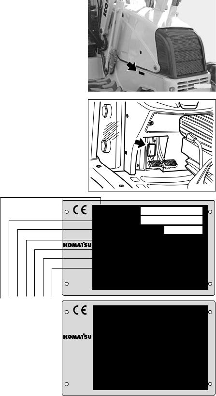
1.4.1 MACHINE SERIAL NUMBER
The machine serial number is stamped on the front part of the main frame, on the right side.
|
RWAB0070 |
|
1.4.2 MACHINE IDENTIFICATION PLATE |
|
|
The Komatsu Utility backhoe loaders described in this manual |
|
|
are provided with the CE mark, which certifies that they are in |
|
|
compliance with the CE harmonized standards. |
|
|
The plate with the mark is applied inside the operator’s cab, on |
|
|
the left vertical wall of the frame, in correspondence with the |
|
|
brake pedals. |
|
|
RWA04680 |
|
|
MODELLO |
— MODEL |
|
TYP |
— MODELE |
MATRICOLA N˚ — SERIAL N˚
|
FABR. NR. |
— SERIE NR. |
|
|
ANNO |
— YEAR |
|
|
BAUJAHR |
— ANNEE |
|
|
MASSA TOTALE MAX |
— TOTAL MAX WEIGHT |
|
|
ZUL. GESAMTGEWICHT |
— POIDS TOTAL MAX |
|
|
POTENZA MOTORE |
— ENGINE POWER |
|
|
LEISTUNG |
— PUISSANCE MOTEUR |
|
|
MASSA MAX ASSE ANT. — MAX WEIGHT FRONT AXLE |
||
|
ZUL. ACHSLAST VORN |
— POIDS MAX ESSIEU AV |
MASSA MAX ASSE POST. — MAX WEIGHT REAR AXLE ZUL. ACHSLAST HINTEN — POIDS MAX ESSIEU AR
MANUFACTURED BY KOMATSU UTILITY EUROPE S.p.A. 36025 NOVENTA VICENTINA (VI) ITALY
|
21D-98-12580 |
||||||||||||
|
RWA34270 |
||||||||||||
|
MODEL |
||||||||||||
|
SERIAL N |
||||||||||||
|
YEAR |
||||||||||||
|
TOTAL MAX WEIGHT |
kg |
|||||||||||
|
ENGINE POWER |
kw |
|||||||||||
|
MAX WEIGHT FRONT AXLE |
kg |
|||||||||||
|
MAX WEIGHT REAR AXLE |
kg |
|||||||||||
MANUFACTURED BY KOMATSU UTILITY EUROPE S.p.A. 36025 NOVENTA VICENTINA (VI) ITALY
6

INTRODUCTION
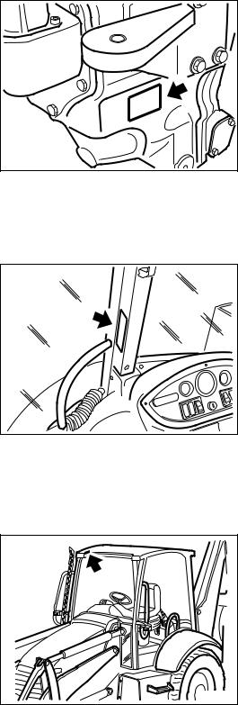
1.4.3ENGINE SERIAL NUMBER AND EXHAUST GAS EMISSION PLATE
The engine serial number is stamped on the plate positioned on the rear side of the tappet cover.
RWAB0480
The plate regarding the exhaust emission regulations is applied to the front side of the tappet cover.
RWAB0620
1.4.4 FRONT AXLE SERIAL NUMBER
The serial number of the front axle is stamped on the plate positioned on the right side of the axle body.
1.4.5 REAR AXLE SERIAL NUMBER
The serial number of the rear axle is stamped on the plate positioned on the right side of the axle body.
INTRODUCTION
1.4.6 TRANSMISSION SERIAL NUMBER
The transmission serial number is stamped on the plate postioned on the right side of the transmission case.
RWA02540
1.4.7 CAB SERIAL NUMBER
The cab serial number is stamped on the plate positioned on the right center pillar.
1.4.8CANOPY SERIAL NUMBER (if provided)
The serial number is stamped on the plate positioned inside the canopy, on the front right part.
8
![]()
INTRODUCTION
1.4.9 SERIAL NUMBERS AND DEALER’S ADDRESS
|
Machine n. |
Model |
||||||||
|
Engine n. |
|||||||||
|
Front axle n. |
|||||||||
|
Rear axle n. |
|||||||||
|
Transmission n. |
|||||||||
|
Cab n. |
|||||||||
|
Canopy n. |
|||||||||
|
Dealer: |
|||||||||
Address:
Tel.
Person to contact:
NOTES:
9
THIS PAGE WAS INTENTIONALLY LEFT EMPTY
10
TABLE OF CONTENTS
|
Page |
|||
|
TABLE OF CONTENTS |
|||
|
1.1 |
FOREWORD . . . . . . . . . . . . . . . . . . . . . . . . . . . . . . . . . . . . . . . . . . . . . . . . . . . . . . . . . . . . . . . . . . . . . |
1 |
|
|
1.2 |
INFORMATION ON SAFETY . . . . . . . . . . . . . . . . . . . . . . . . . . . . . . . . . . . . . . . . . . . . . . . . . . . . . . . . |
2 |
|
|
1.3 |
INTRODUCTION. . . . . . . . . . . . . . . . . . . . . . . . . . . . . . . . . . . . . . . . . . . . . . . . . . . . . . . . . . . . . . . . . . |
4 |
|
|
1.3.1 |
INTENDED USES . . . . . . . . . . . . . . . . . . . . . . . . . . . . . . . . . . . . . . . . . . . . . . . . . . . . . . . . . . |
4 |
|
|
1.3.2 |
IMPROPER OR UNAUTHORIZED USES . . . . . . . . . . . . . . . . . . . . . . . . . . . . . . . . . . . . . . . . |
4 |
|
|
1.3.3 |
MAIN CHARACTERISTICS . . . . . . . . . . . . . . . . . . . . . . . . . . . . . . . . . . . . . . . . . . . . . . . . . . |
5 |
|
|
1.3.4 |
RUNNING-IN . . . . . . . . . . . . . . . . . . . . . . . . . . . . . . . . . . . . . . . . . . . . . . . . . . . . . . . . . . . . . |
5 |
|
|
1.4 |
PRODUCT IDENTIFICATION. . . . . . . . . . . . . . . . . . . . . . . . . . . . . . . . . . . . . . . . . . . . . . . . . . . . . . . . |
6 |
|
|
1.4.1 |
MACHINE SERIAL NUMBER . . . . . . . . . . . . . . . . . . . . . . . . . . . . . . . . . . . . . . . . . . . . . . . . . |
6 |
|
|
1.4.2 |
MACHINE IDENTIFICATION PLATE . . . . . . . . . . . . . . . . . . . . . . . . . . . . . . . . . . . . . . . . . . . |
6 |
|
|
1.4.3 |
ENGINE SERIAL NUMBER AND EXHAUST GAS EMISSION PLATE. . . . . . . . . . . . . . . . . . |
7 |
|
|
1.4.4 |
FRONT AXLE SERIAL NUMBER . . . . . . . . . . . . . . . . . . . . . . . . . . . . . . . . . . . . . . . . . . . . . . |
7 |
|
|
1.4.5 |
REAR AXLE SERIAL NUMBER . . . . . . . . . . . . . . . . . . . . . . . . . . . . . . . . . . . . . . . . . . . . . . . |
7 |
|
|
1.4.6 |
TRANSMISSION SERIAL NUMBER . . . . . . . . . . . . . . . . . . . . . . . . . . . . . . . . . . . . . . . . . . . |
8 |
|
|
1.4.7 |
CAB SERIAL NUMBER . . . . . . . . . . . . . . . . . . . . . . . . . . . . . . . . . . . . . . . . . . . . . . . . . . . . . . |
8 |
|
|
1.4.8 |
CANOPY SERIAL NUMBER (if provided) . . . . . . . . . . . . . . . . . . . . . . . . . . . . . . . . . . . . . . . . |
8 |
|
|
1.4.9 |
SERIAL NUMBERS AND DEALER’S ADDRESS . . . . . . . . . . . . . . . . . . . . . . . . . . . . . . . . . . |
9 |
|
|
SAFETY AND ACCIDENT PREVENTION |
|||
|
2.1 SAFETY, NOISE AND VIBRATION PLATES . . . . . . . . . . . . . . . . . . . . . . . . . . . . . . . . . . . . . . . . . . . |
20 |
||
|
2.1.1 |
POSITION OF THE SAFETY PLATES . . . . . . . . . . . . . . . . . . . . . . . . . . . . . . . . . . . . . . . . . . |
20 |
|
|
2.1.2 |
PICTOGRAMS AND RELEVANT MEANINGS . . . . . . . . . . . . . . . . . . . . . . . . . . . . . . . . . . . . |
22 |
|
|
2.1.3 |
POSITION OF THE NOISE PLATES ON MACHINES WITH CAB (model WB91R-2) . . . . . . |
26 |
|
|
2.1.4 |
POSITION OF THE NOISE PLATES ON MACHINES WITH CAB (model WB93R-2) . . . . . . |
27 |
|
|
2.1.5 |
VIBRATIONS TO WHICH THE OPERATOR IS SUBJECTED . . . . . . . . . . . . . . . . . . . . . . . . |
28 |
|
|
2.2 |
GENERAL PRECAUTIONS . . . . . . . . . . . . . . . . . . . . . . . . . . . . . . . . . . . . . . . . . . . . . . . . . . . . . . . . . |
29 |
|
|
2.2.1 |
GENERAL SAFETY RULES . . . . . . . . . . . . . . . . . . . . . . . . . . . . . . . . . . . . . . . . . . . . . . . . . . |
29 |
|
|
2.2.2 |
SAFETY DEVICES AND GUARDS . . . . . . . . . . . . . . . . . . . . . . . . . . . . . . . . . . . . . . . . . . . . |
29 |
|
|
2.2.3 |
CLOTHING AND PERSONAL PROTECTION ITEMS . . . . . . . . . . . . . . . . . . . . . . . . . . . . . . |
29 |
|
|
2.2.4 |
UNAUTHORIZED MODIFICATIONS . . . . . . . . . . . . . . . . . . . . . . . . . . . . . . . . . . . . . . . . . . . |
30 |
|
|
2.2.5 |
LEAVING THE OPERATOR’S SEAT . . . . . . . . . . . . . . . . . . . . . . . . . . . . . . . . . . . . . . . . . . . |
30 |
|
|
2.2.6 |
GETTING ON AND OFF THE MACHINE . . . . . . . . . . . . . . . . . . . . . . . . . . . . . . . . . . . . . . . . |
31 |
|
|
2.2.7 |
CHECKING THE REAR-VIEW MIRRORS . . . . . . . . . . . . . . . . . . . . . . . . . . . . . . . . . . . . . . |
31 |
|
|
2.2.8 |
PREVENTING FIRES DUE TO FUEL AND OIL . . . . . . . . . . . . . . . . . . . . . . . . . . . . . . . . . . . |
31 |
|
|
2.2.9 |
PREVENTING BURNS . . . . . . . . . . . . . . . . . . . . . . . . . . . . . . . . . . . . . . . . . . . . . . . . . . . . . . |
32 |
|
|
2.2.10 |
PREVENTING DAMAGE DUE TO ASBESTOS POWDER . . . . . . . . . . . . . . . . . . . . . . . . . . |
32 |
|
|
2.2.11 |
PREVENTING DAMAGE CAUSED BY THE WORK EQUIPMENT . . . . . . . . . . . . . . . . . . . . |
33 |
|
|
2.2.12 |
FIRE EXTINGUISHERS AND FIRST AID KIT . . . . . . . . . . . . . . . . . . . . . . . . . . . . . . . . . . . . |
33 |
|
|
2.2.13 |
PRECAUTIONS CONCERNING THE CAB STRUCTURE . . . . . . . . . . . . . . . . . . . . . . . . . . . |
33 |
|
|
2.2.14 |
PRECAUTIONS CONCERNING THE EQUIPMENT . . . . . . . . . . . . . . . . . . . . . . . . . . . . . . . . |
33 |
|
|
2.3 PRECAUTIONS TO BE TAKEN BEFORE STARTING THE ENGINE . . . . . . . . . . . . . . . . . . . . . . . . |
34 |
||
|
2.3.1 |
SAFETY ON THE WORK SITE . . . . . . . . . . . . . . . . . . . . . . . . . . . . . . . . . . . . . . . . . . . . . . . |
34 |
|
|
2.3.2 |
FIRE PREVENTION . . . . . . . . . . . . . . . . . . . . . . . . . . . . . . . . . . . . . . . . . . . . . . . . . . . . . . . . |
34 |
|
|
2.3.3 |
PRECAUTIONS TO BE TAKEN FOR THE OPERATOR’S CAB . . . . . . . . . . . . . . . . . . . . . |
. 34 |
|
|
2.3.4 |
ROOM VENTILATION . . . . . . . . . . . . . . . . . . . . . . . . . . . . . . . . . . . . . . . . . . . . . . . . . . . . . . |
35 |
2.3.5CLEANING WINDOWS, MIRRORS AND LIGHTS — CHECKING THE WINDSHIELD
|
WIPER BLADES AND THE BULBS . . . . . . . . . . . . . . . . . . . . . . . . . . . . . . . . . . . . . . . . . . . . |
35 |
11
TABLE OF CONTENTS
|
Page |
|||
|
2.4 PRECAUTIONS TO BE TAKEN WHEN WORKING . . . . . . . . . . . . . . . . . . . . . . . . . . . . . . . . . . . . . . |
36 |
||
|
2.4.1 |
STARTING THE ENGINE . . . . . . . . . . . . . . . . . . . . . . . . . . . . . . . . . . . . . . . . . . . . . . . . . . . . |
36 |
|
|
2.4.2 |
RULES FOR ROAD TRAVEL . . . . . . . . . . . . . . . . . . . . . . . . . . . . . . . . . . . . . . . . . . . . . . . . . |
36 |
|
|
2.4.3 |
CHECKS FOR TRAVELLING IN REVERSE . . . . . . . . . . . . . . . . . . . . . . . . . . . . . . . . . . . . . . |
37 |
|
|
2.4.4 |
MOVING THE MACHINE . . . . . . . . . . . . . . . . . . . . . . . . . . . . . . . . . . . . . . . . . . . . . . . . . . . . |
37 |
|
|
2.4.5 |
WORKING ON SLOPES . . . . . . . . . . . . . . . . . . . . . . . . . . . . . . . . . . . . . . . . . . . . . . . . . . . . |
38 |
|
|
2.4.6 |
PREVENTING ELECTROCUTION . . . . . . . . . . . . . . . . . . . . . . . . . . . . . . . . . . . . . . . . . . . . . |
39 |
|
|
2.4.7 |
VISIBILITY . . . . . . . . . . . . . . . . . . . . . . . . . . . . . . . . . . . . . . . . . . . . . . . . . . . . . . . . . . . . . . . . |
40 |
|
|
2.4.8 |
WORKING ON ICY OR SNOW-COVERED SURFACES . . . . . . . . . . . . . . . . . . . . . . . . . . . . |
40 |
|
|
2.4.9 |
PREVENTING DAMAGE CAUSED BY THE WORK EQUIPMENT . . . . . . . . . . . . . . . . . . . . |
40 |
|
|
2.4.10 |
WORKING ON LOOSE GROUND . . . . . . . . . . . . . . . . . . . . . . . . . . . . . . . . . . . . . . . . . . . . . |
40 |
|
|
2.4.11 |
PARKING THE MACHINE . . . . . . . . . . . . . . . . . . . . . . . . . . . . . . . . . . . . . . . . . . . . . . . . . . . |
41 |
|
|
2.5 TRANSPORTING THE MACHINE ON MOTOR VEHICLES . . . . . . . . . . . . . . . . . . . . . . . . . . . . . . . . |
42 |
||
|
2.5.1 |
LOADING AND UNLOADING . . . . . . . . . . . . . . . . . . . . . . . . . . . . . . . . . . . . . . . . . . . . . . . . . |
42 |
|
|
2.5.2 |
TRANSPORT . . . . . . . . . . . . . . . . . . . . . . . . . . . . . . . . . . . . . . . . . . . . . . . . . . . . . . . . . . . . . |
42 |
|
|
2.6 |
BATTERY . . . . . . . . . . . . . . . . . . . . . . . . . . . . . . . . . . . . . . . . . . . . . . . . . . . . . . . . . . . . . . . . . . . . . . . |
43 |
|
|
2.6.1 |
PREVENTING RISKS THAT MAY BE DUE TO THE BATTERY . . . . . . . . . . . . . . . . . . . . . |
43 |
|
|
2.6.2 |
STARTING WITH BOOSTER CABLES . . . . . . . . . . . . . . . . . . . . . . . . . . . . . . . . . . . . . . . . . |
43 |
|
|
2.7 PRECAUTIONS FOR THE REMOVAL . . . . . . . . . . . . . . . . . . . . . . . . . . . . . . . . . . . . . . . . . . . . . . . . |
44 |
||
|
2.8 |
PRECAUTIONS FOR MAINTENANCE . . . . . . . . . . . . . . . . . . . . . . . . . . . . . . . . . . . . . . . . . . . . . . . . |
45 |
|
|
2.8.1 |
WARNING PLATES . . . . . . . . . . . . . . . . . . . . . . . . . . . . . . . . . . . . . . . . . . . . . . . . . . . . . . . . |
45 |
|
|
2.8.2 |
TOOLS. . . . . . . . . . . . . . . . . . . . . . . . . . . . . . . . . . . . . . . . . . . . . . . . . . . . . . . . . . . . . . . . . . . |
45 |
|
|
2.8.3 |
PERSONNEL. . . . . . . . . . . . . . . . . . . . . . . . . . . . . . . . . . . . . . . . . . . . . . . . . . . . . . . . . . . . . . |
45 |
|
|
2.8.4 |
EQUIPMENT . . . . . . . . . . . . . . . . . . . . . . . . . . . . . . . . . . . . . . . . . . . . . . . . . . . . . . . . . . . . . |
46 |
|
|
2.8.5 |
WORKING UNDER THE MACHINE . . . . . . . . . . . . . . . . . . . . . . . . . . . . . . . . . . . . . . . . . . . |
46 |
|
|
2.8.6 |
CLEANING THE MACHINE . . . . . . . . . . . . . . . . . . . . . . . . . . . . . . . . . . . . . . . . . . . . . . . . . . |
46 |
|
|
2.8.7 |
USE OF THE ENGINE DURING MAINTENANCE OPERATIONS . . . . . . . . . . . . . . . . . . . . . |
47 |
|
|
2.8.8 |
PERIODICAL CHANGE OF THE PARTS THAT ARE CRITICAL FOR SAFETY . . . . . . . . . . |
47 |
2.8.9STOP THE ENGINE BEFORE CARRYING OUT ANY MAINTENANCE OPERATION
|
OR INSPECTION. . . . . . . . . . . . . . . . . . . . . . . . . . . . . . . . . . . . . . . . . . . . . . . . . . . . . . . . . . . |
48 |
|
2.8.10 RULES TO BE FOLLOWED DURING FUEL OR OIL TOPPING UP . . . . . . . . . . . . . . . . . . . |
49 |
|
2.8.11 CHECKING THE COOLANT LEVEL IN THE RADIATOR . . . . . . . . . . . . . . . . . . . . . . . . . . . |
49 |
|
2.8.12 USING LAMPS . . . . . . . . . . . . . . . . . . . . . . . . . . . . . . . . . . . . . . . . . . . . . . . . . . . . . . . . . . . . |
49 |
|
2.8.13 PRECAUTIONS CONCERNING THE BATTERY AND THE ALTERNATOR . . . . . . . . . . . . . |
50 |
|
2.8.14 PRECAUTIONS CONCERNING THE STARTER . . . . . . . . . . . . . . . . . . . . . . . . . . . . . . . . . . |
50 |
|
2.8.15 HANDLING HIGH-PRESSURE PIPES . . . . . . . . . . . . . . . . . . . . . . . . . . . . . . . . . . . . . . . . . . |
51 |
|
2.8.16 PRECAUTIONS TO BE TAKEN WHEN HANDLING HIGH-PRESSURE OIL . . . . . . . . . . . . . |
51 |
|
2.8.17 PRECAUTIONS FOR MAINTENANCE OPERATIONS AT HIGH TEMPERATURES |
|
|
AND HIGH PRESSURE. . . . . . . . . . . . . . . . . . . . . . . . . . . . . . . . . . . . . . . . . . . . . . . . . . . . . . |
51 |
|
2.8.18 COOLING FAN AND BELT . . . . . . . . . . . . . . . . . . . . . . . . . . . . . . . . . . . . . . . . . . . . . . . . . . . |
52 |
|
2.8.19 WASTE MATERIALS . . . . . . . . . . . . . . . . . . . . . . . . . . . . . . . . . . . . . . . . . . . . . . . . . . . . . . . |
52 |
|
2.8.20 PRECAUTIONS TO BE TAKEN WHEN INFLATING TYRES . . . . . . . . . . . . . . . . . . . . . . . . . |
52 |
|
2.8.21 PRECAUTIONS FOR THE INSTALLATION OF THE EXHAUST SYSTEM TAILPIPE . . . . . . |
53 |
|
2.8.22 PRECAUTIONS FOR THE USE OF THE SYNTHETIC BIODEGRADABLE OIL |
|
|
TYPE HEES. . . . . . . . . . . . . . . . . . . . . . . . . . . . . . . . . . . . . . . . . . . . . . . . . . . . . . . . . . . . . . . |
53 |
12
|
TABLE OF CONTENTS |
|||
|
Page |
|||
|
DESCRIPTION AND USE OF THE MACHINE |
|||
|
3.1 |
SAFETY LOCKS . . . . . . . . . . . . . . . . . . . . . . . . . . . . . . . . . . . . . . . . . . . . . . . . . . . . |
. . . . . . . . . . . . . 56 |
|
|
3.1.1 |
FRONT LOADER LOCKS . . . . . . . . . . . . . . . . . . . . . . . . . . . . . . . . . . . . . . . . |
. . . . . . . . . . . . 56 |
|
|
3.1.2 |
BACKHOE LOCKS . . . . . . . . . . . . . . . . . . . . . . . . . . . . . . . . . . . . . . . . . . . . . |
. . . . . . . . . . . . 58 |
|
|
3.2 |
GENERAL VIEWS . . . . . . . . . . . . . . . . . . . . . . . . . . . . . . . . . . . . . . . . . . . . . . . . . . . . |
. . . . . . . . . . . . 59 |
3.2.1 FRONT GENERAL VIEW . . . . . . . . . . . . . . . . . . . . . . . . . . . . . . . . . . . . . . . . . . . . . . . . . . . . 59 3.2.2 BACKHOE GENERAL VIEW . . . . . . . . . . . . . . . . . . . . . . . . . . . . . . . . . . . . . . . . . . . . . . . . . . 60 3.2.3 CAB INSIDE GENERAL VIEW . . . . . . . . . . . . . . . . . . . . . . . . . . . . . . . . . . . . . . . . . . . . . . . . 61 3.2.3.1 CAB INSIDE GENERAL VIEW (Standard version) . . . . . . . . . . . . . . . . . . . . . . . . 61
3.2.3.2CAB INSIDE GENERAL VIEW (Version with servcontrols available on request) . 62
|
3.3 |
INSTRUMENTS AND CONTROLS . . . . . . . . . . . . . . . . . . . . . . . . . . . . . . . . . . . . . . . . . . . . . . . . . . . |
63 |
||
|
3.3.1 |
FRONT INSTRUMENTS . . . . . . . . . . . . . . . . . . . . . . . . . . . . . . . . . . . . . . . . . . . . . . . . . . . . . |
63 |
||
|
3.3.2 |
SIDE INSTRUMENTS . . . . . . . . . . . . . . . . . . . . . . . . . . . . . . . . . . . . . . . . . . . . . . . . . . . . . . . |
67 |
||
|
3.3.2.1 SIDE INSTRUMENTS (Standard version) . . . . . . . . . . . . . . . . . . . . . . . . . . . . . . . |
67 |
|||
|
3.3.2.2 SIDE INSTRUMENTS (Version with servo controls available on request) . . . . . . |
68 |
|||
|
3.3.3 |
PUSH BUTTONS ON THE FRONT LOADER CONTROL LEVER . . . . . . . . . . . . . . . . . . . . . |
75 |
||
|
3.3.4 |
PUSH BUTTON ON THE GEARSHIFT LEVER . . . . . . . . . . . . . . . . . . . . . . . . . . . . . . . . . . . |
75 |
||
|
3.3.5 |
ELECTRICAL ACCESSORIES . . . . . . . . . . . . . . . . . . . . . . . . . . . . . . . . . . . . . . . . . . . . . . . . |
76 |
||
|
3.3.6 |
MACHINE CONTROLS . . . . . . . . . . . . . . . . . . . . . . . . . . . . . . . . . . . . . . . . . . . . . . . . . . . . . . |
77 |
||
|
3.3.6.1 MACHINE CONTROLS (Standard version) . . . . . . . . . . . . . . . . . . . . . . . . . . . . . . |
77 |
|||
|
3.3.6.2 |
MACHINE CONTROLS (Version with servo controls available upon request) . . . |
78 |
||
|
3.4 |
FUSES AND RELAYS . . . . . . . . . . . . . . . . . . . . . . . . . . . . . . . . . . . . . . . . . . . . . . . . . . . . . . . . . . . . . |
106 |
||
|
3.4.1 |
EQUIPMENT FUSES AND RELAYS . . . . . . . . . . . . . . . . . . . . . . . . . . . . . . . . . . . . . . . . . . . |
106 |
||
|
3.4.1.1 |
FUSES . . . . . . . . . . . . . . . . . . . . . . . . . . . . . . . . . . . . . . . . . . . . . . . . . . . . . . . . . |
107 |
||
|
3.4.1.2 |
RELAYS . . . . . . . . . . . . . . . . . . . . . . . . . . . . . . . . . . . . . . . . . . . . . . . . . . . . . . . . |
108 |
||
|
3.4.2 |
ENGINE FUSES AND RELAYS . . . . . . . . . . . . . . . . . . . . . . . . . . . . . . . . . . . . . . . . . . . . . . . |
108 |
||
|
3.4.2.1 |
FUSES . . . . . . . . . . . . . . . . . . . . . . . . . . . . . . . . . . . . . . . . . . . . . . . . . . . . . . . . . . |
109 |
||
|
3.4.2.2 |
RELAYS . . . . . . . . . . . . . . . . . . . . . . . . . . . . . . . . . . . . . . . . . . . . . . . . . . . . . . . . |
109 |
||
|
3.4.3 |
SIDE DASHBOARD RELAYS . . . . . . . . . . . . . . . . . . . . . . . . . . . . . . . . . . . . . . . . . . . . . . . . . |
110 |
||
|
3.4.4 |
SIDE DASHBOARD RELAYS AND FUSES (Only with servo controls) . . . . . . . . . . . . . . . . . |
110 |
||
|
3.4.2.1 |
FUSES . . . . . . . . . . . . . . . . . . . . . . . . . . . . . . . . . . . . . . . . . . . . . . . . . . . . . . . . . |
110 |
||
|
3.5 GUARDS, CAB AND DRIVER’S SEAT . . . . . . . . . . . . . . . . . . . . . . . . . . . . . . . . . . . . . . . . . . . . . . . . |
111 |
|||
|
3.5.1 |
ENGINE HOOD . . . . . . . . . . . . . . . . . . . . . . . . . . . . . . . . . . . . . . . . . . . . . . . . . . . . . . . . . . . . |
111 |
||
|
3.5.2 |
CANOPY (if provided) . . . . . . . . . . . . . . . . . . . . . . . . . . . . . . . . . . . . . . . . . . . . . . . . . . . . . . . |
111 |
||
|
3.5.3 |
CAB . . . . |
. . . . . . . . . . . . . . . . . . . . . . . . . . . . . . . . . . . . . . . . . . . . . . . . . . . . . . . . . . . . . . . . . |
112 |
|
|
3.5.4 |
VENTILATION AND HEATING . . . . . . . . . . . . . . . . . . . . . . . . . . . . . . . . . . . . . . . . . . . . . . . . |
115 |
||
|
3.5.5 |
AIR CONDITIONER (if installed) . . . . . . . . . . . . . . . . . . . . . . . . . . . . . . . . . . . . . . . . . . . . . . . |
116 |
||
|
3.5.6 |
SEAT . . . |
. . . . . . . . . . . . . . . . . . . . . . . . . . . . . . . . . . . . . . . . . . . . . . . . . . . . . . . . . . . . . . . . . |
118 |
|
|
3.5.6.1 |
SEAT (STANDARD) . . . . . . . . . . . . . . . . . . . . . . . . . . . . . . . . . . . . . . . . . . . . . . . . |
118 |
||
|
3.5.6.2 |
SEAT (OPTIONAL). . . . . . . . . . . . . . . . . . . . . . . . . . . . . . . . . . . . . . . . . . . . . . . . . |
119 |
||
|
3.5.7 |
SAFETY BELT . . . . . . . . . . . . . . . . . . . . . . . . . . . . . . . . . . . . . . . . . . . . . . . . . . . . . . . . . . . . . |
120 |
||
|
3.5.8 |
FIRE EXTINGUISHER . . . . . . . . . . . . . . . . . . . . . . . . . . . . . . . . . . . . . . . . . . . . . . . . . . . . . . |
120 |
||
|
3.5.9 |
FIRST AID KIT . . . . . . . . . . . . . . . . . . . . . . . . . . . . . . . . . . . . . . . . . . . . . . . . . . . . . . . . . . . . |
120 |
||
|
3.5.10 |
TECHNICAL DOCUMENTATION . . . . . . . . . . . . . . . . . . . . . . . . . . . . . . . . . . . . . . . . . . . . . . |
120 |
||
|
3.5.11 |
ADDITIONAL TOOL BOX (if provided) . . . . . . . . . . . . . . . . . . . . . . . . . . . . . . . . . . . . . . . . . . |
121 |
||
|
3.6 USE OF THE MACHINE . . . . . . . . . . . . . . . . . . . . . . . . . . . . . . . . . . . . . . . . . . . . . . . . . . . . . . . . . . . . |
123 |
|||
|
3.6.1 |
CHECKS BEFORE STARTING THE ENGINE . . . . . . . . . . . . . . . . . . . . . . . . . . . . . . . . . . . . |
123 |
||
|
3.6.1.1 |
VISUAL CHECKS . . . . . . . . . . . . . . . . . . . . . . . . . . . . . . . . . . . . . . . . . . . . . . . . . |
123 |
||
|
3.6.1.2 |
DAILY CHECKS . . . . . . . . . . . . . . . . . . . . . . . . . . . . . . . . . . . . . . . . . . . . . . . . . . |
123 |
||
|
3.6.1.3 |
OPERATIONAL CHECKS . . . . . . . . . . . . . . . . . . . . . . . . . . . . . . . . . . . . . . . . . . . |
124 |
13
TABLE OF CONTENTS
|
Page |
||||
|
3.6.2 |
STARTING THE ENGINE . . . . . . . . . . . . . . . . . . . . . . . . . . . . . . . . . . . . . . . . . . . . . . . . . . . |
125 |
||
|
3.6.2.1 STARTING WITH WARM ENGINE OR IN TEMPERATE CLIMATES . . . . . . . . . |
125 |
|||
|
3.6.2.2 STARTING WITH COLD ENGINE OR IN COLD CLIMATES . . . . . . . . . . . . . . . . |
126 |
|||
|
3.6.3 |
WARMING THE ENGINE . . . . . . . . . . . . . . . . . . . . . . . . . . . . . . . . . . . . . . . . . . . . . . . . . . . . |
127 |
||
|
3.6.4 |
HEATING THE HYDRAULIC OIL . . . . . . . . . . . . . . . . . . . . . . . . . . . . . . . . . . . . . . . . . . . . . |
127 |
||
|
3.6.5 |
HOW TO MOVE THE MACHINE . . . . . . . . . . . . . . . . . . . . . . . . . . . . . . . . . . . . . . . . . . . . . . |
128 |
||
|
3.6.5.1 |
DIFFERENTIAL LOCKING . . . . . . . . . . . . . . . . . . . . . . . . . . . . . . . . . . . . . . . . . . |
129 |
||
|
3.6.5.2 ENGAGING THE FOUR-WHEEL DRIVE . . . . . . . . . . . . . . . . . . . . . . . . . . . . . . . |
129 |
|||
|
3.6.5.3 |
WORKING ON SLOPES . . . . . . . . . . . . . . . . . . . . . . . . . . . . . . . . . . . . . . . . . . . |
130 |
||
|
3.6.5.4 |
MAXIMUM IMMERSION DEPTH . . . . . . . . . . . . . . . . . . . . . . . . . . . . . . . . . . . . . |
131 |
||
|
3.7 |
PARKING THE MACHINE . . . . . . . . . . . . . . . . . . . . . . . . . . . . . . . . . . . . . . . . . . . . . . . . . . . . . . . . . . |
132 |
||
|
3.7.1 |
PARKING ON LEVEL GROUND . . . . . . . . . . . . . . . . . . . . . . . . . . . . . . . . . . . . . . . . . . . . . . . |
132 |
||
|
3.7.2 |
PARKING ON SLOPES . . . . . . . . . . . . . . . . . . . . . . . . . . . . . . . . . . . . . . . . . . . . . . . . . . . . . |
133 |
||
|
3.8 |
STOPPING THE ENGINE . . . . . . . . . . . . . . . . . . . . . . . . . . . . . . . . . . . . . . . . . . . . . . . . . . . . . . . . . . |
134 |
||
|
3.9 |
TRANSPORTING THE MACHINE ON MOTOR VEHICLES . . . . . . . . . . . . . . . . . . . . . . . . . . . . . . . . |
135 |
||
|
3.9.1 |
LOADING AND UNLOADING THE MACHINE . . . . . . . . . . . . . . . . . . . . . . . . . . . . . . . . . . . . |
135 |
||
|
3.9.2 |
TRANSPORT . . . . . . . . . . . . . . . . . . . . . . . . . . . . . . . . . . . . . . . . . . . . . . . . . . . . . . . . . . . . . |
136 |
||
|
3.10 |
PRECAUTIONS TO BE TAKEN IN THE COLD SEASON. . . . . . . . . . . . . . . . . . . . . . . . . . . . . . . . . . |
137 |
||
|
3.10.1 |
FUEL AND LUBRICANTS . . . . . . . . . . . . . . . . . . . . . . . . . . . . . . . . . . . . . . . . . . . . . . . . . . . . |
137 |
||
|
3.10.2 |
COOLANT |
. . . . . . . . . . . . . . . . . . . . . . . . . . . . . . . . . . . . . . . . . . . . . . . . . . . . . . . . . . . . . . . . |
137 |
|
|
3.10.3 |
BATTERY |
. . . . . . . . . . . . . . . . . . . . . . . . . . . . . . . . . . . . . . . . . . . . . . . . . . . . . . . . . . . . . . . . |
137 |
|
|
3.10.4 |
OTHER PRECAUTIONS . . . . . . . . . . . . . . . . . . . . . . . . . . . . . . . . . . . . . . . . . . . . . . . . . . . . |
138 |
||
|
3.10.5 |
PRECAUTIONS TO BE TAKEN AT THE END OF WORK . . . . . . . . . . . . . . . . . . . . . . . . . . . |
138 |
||
|
3.11 |
PRECAUTIONS TO BE TAKEN IN THE WARM SEASON . . . . . . . . . . . . . . . . . . . . . . . . . . . . . . . . |
139 |
||
|
3.12 |
USING THE MACHINE AS A LOADER . . . . . . . . . . . . . . . . . . . . . . . . . . . . . . . . . . . . . . . . . . . . . . . |
140 |
||
|
3.12.1 |
BUCKET POSITION INDICATOR . . . . . . . . . . . . . . . . . . . . . . . . . . . . . . . . . . . . . . . . . . . . . |
140 |
||
|
3.12.2 |
ORGANIZING THE WORK AREA . . . . . . . . . . . . . . . . . . . . . . . . . . . . . . . . . . . . . . . . . . . . . |
140 |
||
|
3.12.2.1 LOADING HEAPED AND LEVEL MATERIAL . . . . . . . . . . . . . . . . . . . . . . . . . . . . |
141 |
|||
|
3.12.2.2 LOADING OPERATIONS ON SLOPES . . . . . . . . . . . . . . . . . . . . . . . . . . . . . . . . |
142 |
|||
|
3.12.3 |
CHANGING THE STANDARD FRONT BUCKET . . . . . . . . . . . . . . . . . . . . . . . . . . . . . . . . . . |
142 |
||
|
3.13 USING THE MACHINE AS AN EXCAVATOR . . . . . . . . . . . . . . . . . . . . . . . . . . . . . . . . . . . . . . . . . . |
143 |
|||
|
3.13.1 POSITIONING THE BUCKET ACCORDING TO THE WORK |
||||
|
THAT MUST BE CARRIED OUT . . . . . . . . . . . . . . . . . . . . . . . . . . . . . . . . . . . . . . . . . . . . . . . |
143 |
|||
|
3.13.2 |
POSITIONING THE MACHINE FOR DIGGING OPERATIONS . . . . . . . . . . . . . . . . . . . . . . |
144 |
||
|
3.13.3 |
SLIDING THE BACKHOE UNIT SIDEWARDS . . . . . . . . . . . . . . . . . . . . . . . . . . . . . . . . . . . |
145 |
||
|
3.13.4 |
DIGGING METHOD . . . . . . . . . . . . . . . . . . . . . . . . . . . . . . . . . . . . . . . . . . . . . . . . . . . . . . . . |
146 |
||
|
3.13.5 |
CHANGING THE BACKHOE BUCKET . . . . . . . . . . . . . . . . . . . . . . . . . . . . . . . . . . . . . . . . . |
147 |
||
|
3.14 |
LONG PERIODS OF INACTIVITY . . . . . . . . . . . . . . . . . . . . . . . . . . . . . . . . . . . . . . . . . . . . . . . . . . . . |
148 |
||
|
3.14.1 |
BEFORE THE PERIOD OF INACTIVITY . . . . . . . . . . . . . . . . . . . . . . . . . . . . . . . . . . . . . . . . |
148 |
||
|
3.14.2 |
DURING THE PERIOD OF INACTIVITY . . . . . . . . . . . . . . . . . . . . . . . . . . . . . . . . . . . . . . . . . |
150 |
||
|
3.14.3 |
AFTER THE PERIOD OF INACTIVITY . . . . . . . . . . . . . . . . . . . . . . . . . . . . . . . . . . . . . . . . . . |
150 |
||
|
3.15 |
TROUBLESHOOTING . . . . . . . . . . . . . . . . . . . . . . . . . . . . . . . . . . . . . . . . . . . . . . . . . . . . . . . . . . . . . |
151 |
||
|
3.15.1 |
HOW TO REMOVE THE MACHINE . . . . . . . . . . . . . . . . . . . . . . . . . . . . . . . . . . . . . . . . . . . . |
151 |
||
|
3.15.2 |
AFTER THE FUEL HAS RUN OUT . . . . . . . . . . . . . . . . . . . . . . . . . . . . . . . . . . . . . . . . . . . . |
151 |
||
|
3.15.3 |
IF THE BATTERY IS DOWN . . . . . . . . . . . . . . . . . . . . . . . . . . . . . . . . . . . . . . . . . . . . . . . . . |
152 |
||
|
3.15.3.1 STARTING WITH BOOSTER CABLES . . . . . . . . . . . . . . . . . . . . . . . . . . . . . . . . . |
153 |
|||
|
3.15.4 |
OTHER TROUBLES . . . . . . . . . . . . . . . . . . . . . . . . . . . . . . . . . . . . . . . . . . . . . . . . . . . . . . . . |
154 |
||
|
3.15.4.1 |
ELECTRICAL CIRCUIT . . . . . . . . . . . . . . . . . . . . . . . . . . . . . . . . . . . . . . . . . . . . . |
154 |
||
|
3.15.4.2 |
HYDRAULIC SYSTEM . . . . . . . . . . . . . . . . . . . . . . . . . . . . . . . . . . . . . . . . . . . . . . |
154 |
||
|
3.15.4.3 |
BRAKING SYSTEM . . . . . . . . . . . . . . . . . . . . . . . . . . . . . . . . . . . . . . . . . . . . . . . . |
155 |
||
|
3.15.4.4 |
CONVERTER . . . . . . . . . . . . . . . . . . . . . . . . . . . . . . . . . . . . . . . . . . . . . . . . . . . . |
155 |
||
|
3.15.4.5 |
ENGINE . . . . . . . . . . . . . . . . . . . . . . . . . . . . . . . . . . . . . . . . . . . . . . . . . . . . . . . . . |
156 |
14
TABLE OF CONTENTS
Page
MAINTENANCE
|
4.1 |
GUIDE TO MAINTENANCE . . . . . . . . . . . . . . . . . . . . . . . . . . . . . . . . . . . . . . . . . . . . . . . . . . . . . . . . |
158 |
||
|
4.2 |
MAINTENANCE NOTES . . . . . . . . . . . . . . . . . . . . . . . . . . . . . . . . . . . . . . . . . . . . . . . . . . . . . . . . . . . |
160 |
||
|
4.2.1 NOTES REGARDING THE ENGINE . . . . . . . . . . . . . . . . . . . . . . . . . . . . . . . . . . . . . . . . . . . |
160 |
|||
|
4.2.1.1 |
ENGINE OIL . . . . . . . . . . . . . . . . . . . . . . . . . . . . . . . . . . . . . . . . . . . . . . . . . . . . . . |
160 |
||
|
4.2.1.2 |
COOLANT . . . . . . . . . . . . . . . . . . . . . . . . . . . . . . . . . . . . . . . . . . . . . . . . . . . . . . |
160 |
||
|
4.2.1.3 |
FUEL . . . . . . . . . . . . . . . . . . . . . . . . . . . . . . . . . . . . . . . . . . . . . . . . . . . . . . . . . . . |
161 |
||
|
4.2.2 NOTES REGARDING THE HYDRAULIC SYSTEM . . . . . . . . . . . . . . . . . . . . . . . . . . . . . . . . |
161 |
|||
|
4.2.3 NOTES REGARDING THE ELECTRICAL SYSTEM . . . . . . . . . . . . . . . . . . . . . . . . . . . . . . . |
162 |
|||
|
4.2.4 |
NOTES REGARDING LUBRICATION . . . . . . . . . . . . . . . . . . . . . . . . . . . . . . . . . . . . . . . . . . |
162 |
||
|
4.2.5 PARTS SUBJECT TO WEAR THAT PERIODICALLY NEED CHANGING . . . . . . . . . . . . . . |
163 |
|||
|
4.3 FUEL, COOLANT AND LUBRICANTS . . . . . . . . . . . . . . . . . . . . . . . . . . . . . . . . . . . . . . . . . . . . . . . . |
164 |
|||
|
4.3.1 HOMOLOGATED HEES SYNTHETIC BIODEGRADABLE LUBRICANTS . . . . . . . . . . . . . . . |
166 |
|||
|
4.4 DRIVING TORQUES FOR SCREWS AND NUTS . . . . . . . . . . . . . . . . . . . . . . . . . . . . . . . . . . . . . . . . |
167 |
|||
|
4.4.1 |
STANDARD DRIVING TORQUES . . . . . . . . . . . . . . . . . . . . . . . . . . . . . . . . . . . . . . . . . . . . . |
167 |
||
|
4.4.2 |
SPECIFIC TIGHTENING TORQUES . . . . . . . . . . . . . . . . . . . . . . . . . . . . . . . . . . . . . . . . . . . |
167 |
||
|
4.5 |
LUBRICATION . . |
. . . . . . . . . . . . . . . . . . . . . . . . . . . . . . . . . . . . . . . . . . . . . . . . . . . . . . . . . . . . . . . . . |
168 |
|
|
4.5.1 |
LUBRICATION DIAGRAM . . . . . . . . . . . . . . . . . . . . . . . . . . . . . . . . . . . . . . . . . . . . . . . . . . . |
168 |
||
|
4.5.2 LUBRICATION DIAGRAM (4in1 bucket and pallet forks) . . . . . . . . . . . . . . . . . . . . . . . . . . . . |
169 |
|||
|
4.5.3 LUBRICATION DIAGRAM (Front bucket rapid couplings) . . . . . . . . . . . . . . . . . . . . . . . . . . . |
170 |
|||
|
4.5.4 LUBRICATION DIAGRAM (Telescopic arm) . . . . . . . . . . . . . . . . . . . . . . . . . . . . . . . . . . . . . |
171 |
|||
|
4.5.5 LUBRICATION DIAGRAM (Offset device) . . . . . . . . . . . . . . . . . . . . . . . . . . . . . . . . . . . . . . . |
172 |
|||
|
4.6 PERIODICAL CHANGE OF THE COMPONENTS CONNECTED WITH SAFETY . . . . . . . . . . . . . . . |
173 |
|||
|
4.6.1 CRITICAL PARTS FOR SAFETY . . . . . . . . . . . . . . . . . . . . . . . . . . . . . . . . . . . . . . . . . . . . . . |
174 |
|||
|
4.7 |
MAINTENANCE PLAN . . . . . . . . . . . . . . . . . . . . . . . . . . . . . . . . . . . . . . . . . . . . . . . . . . . . . . . . . . . . . |
178 |
||
|
4.7.1 |
WHEN REQUIRED . . . . . . . . . . . . . . . . . . . . . . . . . . . . . . . . . . . . . . . . . . . . . . . . . . . . . . . . . |
182 |
||
|
4.7.1.a |
CHECKING, CLEANING OR CHANGING THE AIR CLEANER CARTRIDGE . . . |
182 |
||
|
4.7.1.b |
CHECKING AND CLEANING THE CAB AIR FILTER . . . . . . . . . . . . . . . . . . . . . . |
183 |
||
|
4.7.1.c CHECKING AND CLEANING THE RECIRCULATING AIR FILTER |
||||
|
(only for machines with air conditioner) . . . . . . . . . . . . . . . . . . . . . . . . . . . . . . . . . |
184 |
|||
|
4.7.1.d BLEEDING THE BRAKING CIRCUIT . . . . . . . . . . . . . . . . . . . . . . . . . . . . . . . . . . |
185 |
|||
|
4.7.1.e |
CLEANING THE WATER SEPARATOR . . . . . . . . . . . . . . . . . . . . . . . . . . . . . . . . |
186 |
||
|
4.7.1.f |
CHECKING AND ADJUSTING THE FRONT WHEEL TOE-IN . . . . . . . . . . . . . . |
186 |
||
|
4.7.1.g |
CHECKING AND ADJUSTING THE PARKING BRAKE . . . . . . . . . . . . . . . . . . . . |
187 |
||
|
4.7.1.h |
CHECKING THE BRAKING EFFICIENCY . . . . . . . . . . . . . . . . . . . . . . . . . . . . . . |
188 |
||
|
4.7.1.j |
CHECKING AND ADJUSTING THE BRAKE PEDAL STROKE . . . . . . . . . . . . . . |
189 |
||
|
4.7.1.k ADJUSTING THE AUTOMATIC RETURN-TO-DIG DEVICE |
||||
|
OF THE FRONT BUCKET (if installed) . . . . . . . . . . . . . . . . . . . . . . . . . . . . . . . . . |
189 |
|||
|
4.7.1.l |
CHECKING AND ADJUSTING THE STABILIZER SLACK . . . . . . . . . . . . . . . . . . |
190 |
||
|
4.7.2 MAINTENANCE INTERVALS IN CASE OF USE OF THE DEMOLITION HAMMER . . . . . . . |
191 |
|||
|
4.7.2.a |
CHANGING THE HYDRAULIC OIL FILTER . . . . . . . . . . . . . . . . . . . . . . . . . . . . . |
191 |
||
|
4.7.2.b |
CHANGING THE HYDRAULIC OIL . . . . . . . . . . . . . . . . . . . . . . . . . . . . . . . . . . . . |
191 |
||
|
4.7.3 |
CHECKS BEFORE STARTING . . . . . . . . . . . . . . . . . . . . . . . . . . . . . . . . . . . . . . . . . . . . . . . |
192 |
||
|
4.7.3.a |
VARIOUS CHECKS . . . . . . . . . . . . . . . . . . . . . . . . . . . . . . . . . . . . . . . . . . . . . . . |
192 |
||
|
4.7.3.b |
CHECKING THE COOLANT LEVEL . . . . . . . . . . . . . . . . . . . . . . . . . . . . . . . . . . . |
192 |
||
|
4.7.3.c |
CHECKING THE FUEL LEVEL . . . . . . . . . . . . . . . . . . . . . . . . . . . . . . . . . . . . . . . |
193 |
||
|
4.7.3.d |
CHECKING THE ENGINE OIL LEVEL. . . . . . . . . . . . . . . . . . . . . . . . . . . . . . . . . . |
193 |
||
|
4.7.3.e |
CHECKING THE HYDRAULIC CIRCUIT OIL LEVEL . . . . . . . . . . . . . . . . . . . . . . |
194 |
||
|
4.7.3.f |
DRAINING THE WATER SEPARATOR . . . . . . . . . . . . . . . . . . . . . . . . . . . . . . . . |
195 |
||
|
4.7.4 MAINTENANCE EVERY 10 HOURS OF OPERATION . . . . . . . . . . . . . . . . . . . . . . . . . . . . . |
196 |
|||
|
4.7.4.a |
LUBRICATING THE JOINTS . . . . . . . . . . . . . . . . . . . . . . . . . . . . . . . . . . . . . . . . |
196 |
15
TABLE OF CONTENTS
Page
4.7.5MAINTENANCE AFTER THE FIRST 50 HOURS OF OPERATION
|
(Only for machines in which the synthetic biodegradable oil type HEES is used) . . . . . . . . . |
198 |
|
|
4.7.6 MAINTENANCE EVERY 50 HOURS OF OPERATION . . . . . . . . . . . . . . . . . . . . . . . . . . . . . |
198 |
|
|
4.7.6.a |
CHECKING THE RADIATOR FLUID LEVEL . . . . . . . . . . . . . . . . . . . . . . . . . . . . |
198 |
|
4.7.6.b |
CHECKING THE BRAKING SYSTEM OIL LEVEL . . . . . . . . . . . . . . . . . . . . . . . . |
198 |
|
4.7.6.c |
LUBRICATING THE PROPELLER SHAFTS . . . . . . . . . . . . . . . . . . . . . . . . . . . . . |
199 |
|
4.7.6.d |
LUBRICATING THE FRONT AXLE JOINTS CENTRAL COUPLING . . . . . . . . . . |
200 |
|
4.7.6.e |
CHECKING THE TYRE PRESSURE . . . . . . . . . . . . . . . . . . . . . . . . . . . . . . . . . . . |
200 |
|
4.7.6.f |
CHECKING THE ELECTRICAL SYSTEM . . . . . . . . . . . . . . . . . . . . . . . . . . . . . . . |
201 |
|
4.7.7 MAINTENANCE AFTER THE FIRST 250 HOURS OF OPERATION . . . . . . . . . . . . . . . . . . |
202 |
|
|
4.7.8 MAINTENANCE EVERY 250 HOURS OF OPERATION . . . . . . . . . . . . . . . . . . . . . . . . . . . . |
202 |
|
|
4.7.8.a |
ADJUSTING THE FAN BELT TENSION . . . . . . . . . . . . . . . . . . . . . . . . . . . . . . . . |
202 |
|
4.7.8.b ADJUSTING THE A/C COMPRESSOR BELT TENSION |
||
|
(Only for machines with air conditioner) . . . . . . . . . . . . . . . . . . . . . . . . . . . . . . . . |
203 |
|
|
4.7.8.c |
CHECKING THE BATTERY ELECTROLYTE LEVEL . . . . . . . . . . . . . . . . . . . . . . |
204 |
|
4.7.8.d |
CHECKING THE FRONT AXLE OIL LEVELS . . . . . . . . . . . . . . . . . . . . . . . . . . . . |
205 |
|
4.7.8.e |
CHECKING THE REAR AXLE OIL LEVELS . . . . . . . . . . . . . . . . . . . . . . . . . . . . |
205 |
|
4.7.8.f |
CHECKING THE HYDRAULIC TRANSMISSION OIL LEVEL . . . . . . . . . . . . . . . . |
206 |
|
4.7.8.g |
CHECKING THE WHEEL NUT DRIVING TORQUE . . . . . . . . . . . . . . . . . . . . . . . |
206 |
4.7.9MAINTENANCE AFTER THE FIRST 500 HOURS OF OPERATION
|
(Only for machines in which the synthetic biodegradable oil type HEES is used) . . . . . . . . . |
207 |
|
|
4.7.10 MAINTENANCE EVERY 500 HOURS OF OPERATION . . . . . . . . . . . . . . . . . . . . . . . . . . . . |
207 |
|
|
4.7.10.a |
CHANGING THE ENGINE OIL. . . . . . . . . . . . . . . . . . . . . . . . . . . . . . . . . . . . . . . . |
207 |
|
4.7.10.b |
CHANGING THE ENGINE OIL FILTER . . . . . . . . . . . . . . . . . . . . . . . . . . . . . . . . |
208 |
|
4.7.10.c |
CHANGING THE HYDRAULIC SYSTEM OIL FILTER . . . . . . . . . . . . . . . . . . . . . |
209 |
|
4.7.10.d |
CHANGING THE FUEL FILTER . . . . . . . . . . . . . . . . . . . . . . . . . . . . . . . . . . . . . . |
210 |
|
4.7.10.e |
DRAINING THE FUEL TANK . . . . . . . . . . . . . . . . . . . . . . . . . . . . . . . . . . . . . . . . |
211 |
|
4.7.10.f |
DRAINING THE HYDRAULIC OIL TANK |
|
|
(Only for machines in which the synthetic biodegradable oil type HEES is used) . 212 |
||
|
4.7.10.g |
CLEANING THE OUTSIDE OF THE RADIATORS . . . . . . . . . . . . . . . . . . . . . . . . |
213 |
|
4.7.10.h |
CLEANING THE OUTSIDE OF THE A/C CONDENSER |
|
|
(Only for machines with air conditioner) . . . . . . . . . . . . . . . . . . . . . . . . . . . . . . . . . |
214 |
|
|
4.7.11 MAINTENANCE EVERY 1000 HOURS OF OPERATION . . . . . . . . . . . . . . . . . . . . . . . . . . |
215 |
|
|
4.7.11.a |
CHANGING THE FRONT AXLE OIL . . . . . . . . . . . . . . . . . . . . . . . . . . . . . . . . . . . |
215 |
|
4.7.11.b CHANGING THE REAR AXLE OIL . . . . . . . . . . . . . . . . . . . . . . . . . . . . . . . . . . . . |
216 |
|
|
4.7.11.c CHANGING THE HYDRAULIC TRANSMISSION OIL . . . . . . . . . . . . . . . . . . . . . |
217 |
|
|
4.7.11.d |
CHANGING THE HYDRAULIC TRANSMISSION FILTER . . . . . . . . . . . . . . . . . . |
218 |
|
4.7.11.e CHECKING AND ADJUSTING THE ENGINE VALVE CLEARANCE . . . . . . . . . . |
218 |
|
|
4.7.12 MAINTENANCE EVERY 2000 HOURS OF OPERATION . . . . . . . . . . . . . . . . . . . . . . . . . . . |
219 |
|
|
4.7.12.a |
CHANGING THE HYDRAULIC SYSTEM OIL AND CLEANING THE SUCTION |
|
|
FILTER . . . . . . . . . . . . . . . . . . . . . . . . . . . . . . . . . . . . . . . . . . . . . . . . . . . . . . . . . |
219 |
|
|
4.7.12.b |
CHANGING THE COOLANT . . . . . . . . . . . . . . . . . . . . . . . . . . . . . . . . . . . . . . . . . |
222 |
|
4.7.12.c |
CHANGING THE BRAKING SYSTEM OIL . . . . . . . . . . . . . . . . . . . . . . . . . . . . . . |
224 |
|
4.7.12.d |
CHECKING THE ALTERNATOR AND THE STARTER. . . . . . . . . . . . . . . . . . . . . |
225 |
|
4.7.12.e CHECKING THE QUANTITY OF COOLANT IN THE A/C SYSTEM |
||
|
(Only for machines with air conditioner) . . . . . . . . . . . . . . . . . . . . . . . . . . . . . . . . |
225 |
|
|
4.7.13 MAINTENANCE EVERY 4000 HOURS OF OPERATION . . . . . . . . . . . . . . . . . . . . . . . . . . . |
226 |
|
|
4.7.13.a |
CHANGING THE A/C DEHYDRATING FILTER |
|
|
(Only for machines with air conditioner) . . . . . . . . . . . . . . . . . . . . . . . . . . . . . . . . |
226 |
|
|
4.7.13.a |
CHECKING THE OPERATING CONDITIONS OF THE A/C COMPRESSOR |
|
|
(Only for machines with air conditioner) . . . . . . . . . . . . . . . . . . . . . . . . . . . . . . . . . |
226 |
16
TABLE OF CONTENTS
Page
TECHNICAL SPECIFICATIONS
|
5.1 TECHNICAL DATA. . . . . . . . . . . . . . . . . . . . . . . . . . . . . . . . . . . . . . . . . . . . . . . . . . . . . . . . . . . . . . . . |
228 |
||
|
5.1.1 |
STANDARD OVERALL DIMENSIONS . . . . . . . . . . . . . . . . . . . . . . . . . . . . . . . . . . . . . . . . . . |
228 |
|
|
5.1.1.1 STANDARD OVERALL DIMENSIONS WITH CENTERED BACKHOE . . . . . . . . . |
228 |
||
|
5.1.1.2 STANDARD OVERALL DIMENSIONS WITH FOLDED BACKHOE . . . . . . . . . . . |
228 |
||
|
5.1.2 |
TECHNICAL CHARACTERISTICS . . . . . . . . . . . . . . . . . . . . . . . . . . . . . . . . . . . . . . . . . . . . . |
229 |
|
|
5.1.2.1 |
TECHNICAL CHARACTERISTICS WB91R-2 . . . . . . . . . . . . . . . . . . . . . . . . . . . . |
229 |
|
|
5.1.2.2 |
TECHNICAL CHARACTERISTICS WB93R-2 . . . . . . . . . . . . . . . . . . . . . . . . . . . . |
230 |
|
|
5.1.3 |
LIFTING CAPACITIES . . . . . . . . . . . . . . . . . . . . . . . . . . . . . . . . . . . . . . . . . . . . . . . . . . . . . . |
231 |
|
|
5.1.3.1 |
SYMBOL TABLE . . . . . . . . . . . . . . . . . . . . . . . . . . . . . . . . . . . . . . . . . . . . . . . . . . |
231 |
|
|
5.1.3.2 LIFTING CAPACITY WB91R-2 (STANDARD BOOM) . . . . . . . . . . . . . . . . . . . . . . |
232 |
||
|
5.1.3.3 LIFTING CAPACITY WB91R-2 (OFFSET BOOM). . . . . . . . . . . . . . . . . . . . . . . . . |
233 |
||
|
5.1.3.4 LIFTING CAPACITY WB93R-2 (STANDARD BOOM) . . . . . . . . . . . . . . . . . . . . . |
234 |
||
|
5.1.3.5 LIFTING CAPACITY WB93R-2 (OFFSET BOOM). . . . . . . . . . . . . . . . . . . . . . . . . |
235 |
AUTHORIZED OPTIONAL EQUIPMENT
|
6.1 AUTHORIZED OPTIONAL EQUIPMENT . . . . . . . . . . . . . . . . . . . . . . . . . . . . . . . . . . . . . . . . . . . . . . |
238 |
|
6.1.1 PRECAUTIONS REGARDING SAFETY . . . . . . . . . . . . . . . . . . . . . . . . . . . . . . . . . . . . . . . . |
238 |
|
6.1.2 CHARACTERISTICS OF THE OPTIONAL EQUIPMENT . . . . . . . . . . . . . . . . . . . . . . . . . . . . |
239 |
|
6.1.2.1 CHARACTERISTICS OF THE OPTIONAL EQUIPMENT |
|
|
FOR MODEL WB91R-2 . . . . . . . . . . . . . . . . . . . . . . . . . . . . . . . . . . . . . . . . . . . . . |
239 |
|
6.1.2.2 CHARACTERISTICS OF THE OPTIONAL EQUIPMENT |
|
|
FOR MODEL WB93R-2 . . . . . . . . . . . . . . . . . . . . . . . . . . . . . . . . . . . . . . . . . . . . . |
240 |
|
6.2 FRONT EQUIPMENT QUICK COUPLING DEVICES . . . . . . . . . . . . . . . . . . . . . . . . . . . . . . . . . . . . |
241 |
|
|
6.2.1 MANUAL CONTROL QUICK COUPLING . . . . . . . . . . . . . . . . . . . . . . . . . . . . . . . . . . . . . . . |
241 |
|
|
6.2.2 |
HYDRAULIC CONTROL QUICK COUPLING FOR STANDARD BUCKET . . . . . . . . . . . . . . |
242 |
|
6.2.3 |
HYDRAULIC CONTROL QUICK COUPLING FOR 4IN1 BUCKET AND OPTIONAL |
|
|
EQUIPMENT WITH UNIDIRECTIONAL OIL FLOW . . . . . . . . . . . . . . . . . . . . . . . . . . . . . . . . |
242 |
|
6.3 4in1 BUCKET . . . . . . . . . . . . . . . . . . . . . . . . . . . . . . . . . . . . . . . . . . . . . . . . . . . . . . . . . . . . . . . . . . . |
243 |
|
|
6.3.1 |
DESCRIPTION AND CONTROLS. . . . . . . . . . . . . . . . . . . . . . . . . . . . . . . . . . . . . . . . . . . . . . |
243 |
|
6.3.2 |
SAFETY DEVICES . . . . . . . . . . . . . . . . . . . . . . . . . . . . . . . . . . . . . . . . . . . . . . . . . . . . . . . . . |
243 |
|
6.3.3 INSTALLING THE 4in1 BUCKET . . . . . . . . . . . . . . . . . . . . . . . . . . . . . . . . . . . . . . . . . . . . . |
244 |
|
|
6.3.4 USING THE 4in1 BUCKET . . . . . . . . . . . . . . . . . . . . . . . . . . . . . . . . . . . . . . . . . . . . . . . . . . |
245 |
|
|
6.3.5 |
MAINTENANCE. . . . . . . . . . . . . . . . . . . . . . . . . . . . . . . . . . . . . . . . . . . . . . . . . . . . . . . . . . . . |
245 |
|
6.4 |
PALLET FORKS . . . . . . . . . . . . . . . . . . . . . . . . . . . . . . . . . . . . . . . . . . . . . . . . . . . . . . . . . . . . . . . . . |
246 |
|
|
6.4.1 |
DESCRIPTION . . . . . . . . . . . . . . . . . . . . . . . . . . . . . . . . . . . . . . . . . . . . . . . . . . . . . . . . . . . . |
246 |
|
|
6.4.2 |
SAFETY DEVICES . . . . . . . . . . . . . . . . . . . . . . . . . . . . . . . . . . . . . . . . . . . . . . . . . . . . . . . . . |
246 |
|
|
6.4.3 |
USING THE FORKS . . . . . . . . . . . . . . . . . . . . . . . . . . . . . . . . . . . . . . . . . . . . . . . . . . . . . . . . |
247 |
|
|
6.4.3.1 PREPARING THE PALLET FORKS FOR USE . . . . . . . . . . . . . . . . . . . . . . . . . . |
247 |
||
|
6.4.3.2 OVERTURNING THE FORKS FOR TRAVEL ON ROADS . . . . . . . . . . . . . . . . . . |
248 |
||
|
6.4.4 |
REMOVING THE FORKS . . . . . . . . . . . . . . . . . . . . . . . . . . . . . . . . . . . . . . . . . . . . . . . . . . . . |
249 |
|
|
6.4.5 |
INSTALLING THE FORKS . . . . . . . . . . . . . . . . . . . . . . . . . . . . . . . . . . . . . . . . . . . . . . . . . . . |
249 |
|
|
6.4.6 |
MAINTENANCE. . . . . . . . . . . . . . . . . . . . . . . . . . . . . . . . . . . . . . . . . . . . . . . . . . . . . . . . . . . . |
249 |
|
|
6.5 |
BACKHOE TELESCOPIC ARM . . . . . . . . . . . . . . . . . . . . . . . . . . . . . . . . . . . . . . . . . . . . . . . . . . . . . |
250 |
|
|
6.5.1 |
DESCRIPTION AND CONTROL . . . . . . . . . . . . . . . . . . . . . . . . . . . . . . . . . . . . . . . . . . . . . . |
250 |
|
|
6.5.1.1 VERSION WITH STANDARD CONTROLS . . . . . . . . . . . . . . . . . . . . . . . . . . . . . . |
250 |
||
|
6.5.1.2 VERSION WITH SERVO CONTROLS (if installed) . . . . . . . . . . . . . . . . . . . . . . . |
250 |
17
TABLE OF CONTENTS
|
Page |
|||
|
6.5.2 |
SAFETY DEVICES . . . . . . . . . . . . . . . . . . . . . . . . . . . . . . . . . . . . . . . . . . . . . . . . . . . . . . . . . |
251 |
|
|
6.5.3 USING THE TELESCOPIC ARM . . . . . . . . . . . . . . . . . . . . . . . . . . . . . . . . . . . . . . . . . . . . . . |
251 |
||
|
6.5.4 |
MAINTENANCE . . . . . . . . . . . . . . . . . . . . . . . . . . . . . . . . . . . . . . . . . . . . . . . . . . . . . . . . . . . |
252 |
|
|
6.5.4.1 ADJUSTING THE GUIDE SLACK . . . . . . . . . . . . . . . . . . . . . . . . . . . . . . . . . . . . . |
252 |
||
|
6.6 ARRANGEMENT FOR THE INSTALLATION OF THE DEMOLITION HAMMER. . . . . . . . . . . . . . . . |
254 |
||
|
6.6.1 |
DESCRIPTION AND CONTROL . . . . . . . . . . . . . . . . . . . . . . . . . . . . . . . . . . . . . . . . . . . . . . |
254 |
|
|
6.6.1.1 VERSION WITH STANDARD CONTROLS . . . . . . . . . . . . . . . . . . . . . . . . . . . . . . |
254 |
||
|
6.6.1.2 VERSION WITH SERVO CONTROLS (if installed) . . . . . . . . . . . . . . . . . . . . . . . |
254 |
||
|
6.6.2 USE OF THE DEMOLITION HAMMER AND RULES TO BE OBSERVED. . . . . . . . . . . . . . . |
255 |
||
|
6.6.3 INSTALLING AND REMOVING THE DEMOLITION HAMMER . . . . . . . . . . . . . . . . . . . . . . . |
259 |
||
|
6.6.3.1 |
INSTALLING THE HAMMER . . . . . . . . . . . . . . . . . . . . . . . . . . . . . . . . . . . . . . . . . |
259 |
|
|
6.6.3.2 |
REMOVING THE HAMMER . . . . . . . . . . . . . . . . . . . . . . . . . . . . . . . . . . . . . . . . . . |
261 |
|
|
6.6.4 |
USING THE HAMMER . . . . . . . . . . . . . . . . . . . . . . . . . . . . . . . . . . . . . . . . . . . . . . . . . . . . . . |
261 |
|
|
6.6.5 |
MAINTENANCE . . . . . . . . . . . . . . . . . . . . . . . . . . . . . . . . . . . . . . . . . . . . . . . . . . . . . . . . . . . |
261 |
|
|
6.7 APPLICATION OF THE OFFSET DEVICE . . . . . . . . . . . . . . . . . . . . . . . . . . . . . . . . . . . . . . . . . . . . . |
262 |
||
|
6.7.1 |
DESCRIPTION AND CONTROL . . . . . . . . . . . . . . . . . . . . . . . . . . . . . . . . . . . . . . . . . . . . . . |
262 |
|
|
6.7.1.1 VERSION WITH STANDARD CONTROLS . . . . . . . . . . . . . . . . . . . . . . . . . . . . . . |
262 |
||
|
6.7.1.2 VERSION WITH SERVO CONTROLS (if installed) . . . . . . . . . . . . . . . . . . . . . . . . |
263 |
||
|
6.7.2 |
MAINTENANCE. . . . . . . . . . . . . . . . . . . . . . . . . . . . . . . . . . . . . . . . . . . . . . . . . . . . . . . . . . . . |
263 |
6.8ARRANGEMENT FOR THE OPERATION OF OPTIONAL EQUIPMENT WITH UNIDIRECTIONAL
|
OIL FLOW . . . . . . . . . . . . . . . . . . . . . . . . . . . . . . . . . . . . . . . . . . . . . . . . . . . . . . . . . . . . . . . . . . . . . . |
264 |
|
|
6.8.1 |
DESCRIPTION AND CONTROL . . . . . . . . . . . . . . . . . . . . . . . . . . . . . . . . . . . . . . . . . . . . . . |
264 |
|
6.8.1.1 VERSION WITH STANDARD CONTROLS . . . . . . . . . . . . . . . . . . . . . . . . . . . . . . |
264 |
|
|
6.8.1.2 VERSION WITH SERVO CONTROLS (if installed) . . . . . . . . . . . . . . . . . . . . . . . |
264 |
|
|
6.8.2 INSTALLING AND CONNECTING THE EQUIPMENT . . . . . . . . . . . . . . . . . . . . . . . . . . . . . . |
265 |
|
|
6.8.3 |
MAINTENANCE. . . . . . . . . . . . . . . . . . . . . . . . . . . . . . . . . . . . . . . . . . . . . . . . . . . . . . . . . . . . |
265 |
|
6.9 ARRANGEMENT FOR THE INSTALLATION OF THE CLAMSHELL BUCKET . . . . . . . . . . . . . . . . |
266 |
|
|
6.9.1 |
DESCRIPTION AND CONTROL . . . . . . . . . . . . . . . . . . . . . . . . . . . . . . . . . . . . . . . . . . . . . . |
266 |
|
6.9.1.1 VERSION WITH STANDARD CONTROLS . . . . . . . . . . . . . . . . . . . . . . . . . . . . . . |
266 |
|
|
6.9.1.2 VERSION WITH SERVO CONTROLS (if installed) . . . . . . . . . . . . . . . . . . . . . . . . |
267 |
|
|
6.9.2 INSTALLING THE CLAMSHELL BUCKET . . . . . . . . . . . . . . . . . . . . . . . . . . . . . . . . . . . . . . . |
268 |
|
|
6.9.3 USING THE CLAMSHELL BUCKET . . . . . . . . . . . . . . . . . . . . . . . . . . . . . . . . . . . . . . . . . . . . |
269 |
|
|
6.9.4 |
MAINTENANCE. . . . . . . . . . . . . . . . . . . . . . . . . . . . . . . . . . . . . . . . . . . . . . . . . . . . . . . . . . . . |
269 |
|
6.10 ARRANGEMENT FOR THE INSTALLATION OF THE MANUAL HYDRAULIC HAMMER . . . . . . . . |
270 |
||
|
6.10.1 |
DESCRIPTION AND CONTROL . . . . . . . . . . . . . . . . . . . . . . . . . . . . . . . . . . . . . . . . . . . . . . . |
270 |
|
|
6.10.2 CONNECTING AND REMOVING THE HAMMER . . . . . . . . . . . . . . . . . . . . . . . . . . . . . . . . . |
271 |
||
|
6.10.2.1 |
CONNECTING THE HAMMER . . . . . . . . . . . . . . . . . . . . . . . . . . . . . . . . . . . . . . . |
271 |
|
|
6.10.2.2 |
REMOVING THE CONNECTIONS . . . . . . . . . . . . . . . . . . . . . . . . . . . . . . . . . . . . |
271 |
|
|
6.10.3 |
USING THE HAMMER . . . . . . . . . . . . . . . . . . . . . . . . . . . . . . . . . . . . . . . . . . . . . . . . . . . . . . |
272 |
|
|
6.10.4 |
MAINTENANCE. . . . . . . . . . . . . . . . . . . . . . . . . . . . . . . . . . . . . . . . . . . . . . . . . . . . . . . . . . . . |
272 |
|
6.11 |
LOAD STABILIZER SYSTEM (LSS) (Optional) . . . . . . . . . . . . . . . . . . . . . . . . . . . . . . . . . . . . . . . . |
273 |
|
|
6.11.1 ACCUMULATOR OF THE LOAD STABILIZER SYSTEM (LSS) . . . . . . . . . . . . . . . . . . . . . . |
273 |
||
|
6.12 |
REAR EQUIPMENT RAPID COUPLING DEVICE . . . . . . . . . . . . . . . . . . . . . . . . . . . . . . . . . . . . . . . |
274 |
|
|
6.12.1 |
EQUIPMENT COUPLING AND RELEASE PROCEDURE . . . . . . . . . . . . . . . . . . . . . . . . . . . |
275 |
|
|
6.12.2 |
MAINTENANCE. . . . . . . . . . . . . . . . . . . . . . . . . . . . . . . . . . . . . . . . . . . . . . . . . . . . . . . . . . . . |
277 |
18
![]()
SAFETY AND ACCIDENT PREVENTION
SAFETY, NOISE AND VIBRATION PLATES
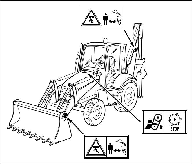
2.1SAFETY, NOISE AND VIBRATION PLATES
2.1.1 POSITION OF THE SAFETY PLATES
•The safety plates must always be legible and in good conditions; for this reason, if they are dirty with dust, oil or grease, it is necessary to clean them with a solution made of water and detergent.
Do not use fuel, petrol or solvents.
•If the plates are damaged, ask for new ones to Komatsu Utility or to your Komatsu Utility Dealer.
•In case of replacement of a component provided with a safety plate, make sure that this plate is applied also on the new piece.
•The machine can be provided with other plates in addition to those indicated below; keep also to the instructions given in the additional plates, in any case.
|
RWA30450 |
|
RWA00020 |
|
RWA00010 |
|
RWA00020 |
|
20 |

SAFETY, NOISE AND VIBRATION PLATES
|
RWA30460 |
|
RWA00030 |
|
RWA00020 |
|
RWA00190 |
|
RWA00020 |
|
RWA00150 |
RWA00160 |
|
RWA37700 |
|
|
21 |
SAFETY, NOISE AND VIBRATION PLATES
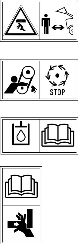
2.1.2 PICTOGRAMS AND RELEVANT MEANINGS
The warning and danger plates applied onto the machine are accompanied or represented by pictograms.
The personnel in charge with the operation and maintenance of the machine must know the symbols contained in the pictograms perfectly; the following description illustrates what they look like and their respective meanings.
DANGER IN THE WORK AREA
• Do not approach or stand in the equipment operating radius when the boom and the bucket are raised.
RWA00020
DO NOT OPEN THE HOOD
• Do not open or remove the hood when the engine is running.
FILLING THE HYDRAULIC SYSTEM WITH
OIL
(Only for machines in which the synthetic biodegradable oil type HEES is used)
OVERTURNING THE FORKS
•When the forks are overturned for use or storage, be careful to the grasping points, since hands and feet may be injured and even cut.
22
CONSULT THE MANUAL
•Carefully read the contents of the manual before using the machine or performing maintenance operations.
SAFETY, NOISE AND VIBRATION PLATES
HYDRAULIC OIL TOPPING UP
RWA00050
REFUELLING
D
RWA00040
ENGINE LUBRICATING OIL FILTER
RWA00080
FUEL FILTER
D
RWA00060
ENGINE AIR SUCTION FILTER
RWA00090
23
SAFETY, NOISE AND VIBRATION PLATES
ENGINE COOLANT
RWA00130
ENGINE COOLANT PRESSURE
RWA00110
HYDRAULIC OIL LEVEL
RWA00100
HYDRAULIC OIL FILTER
RWA00070
ELECTRIC OUTLET
RWA00120 12 V
TRANSMISSION OIL LEVEL
RWA00180
HYDRAULIC TRANSMISSION OIL FILTER
RWA00170
24

ANCHORAGE POINT
EMERGENCY EXIT
BOOM LOCK
SWING LOCK
BRAKE OIL
DO NOT LIFT MORE THAN 1000 kg
SAFETY, NOISE AND VIBRATION PLATES
RWA00190
RWA00150
RWA00140
25

SAFETY, NOISE AND VIBRATION PLATES
2.1.3POSITION OF THE NOISE PLATES ON MACHINES WITH CAB (model WB91R-2)
•The noise plates must always be legible and in good conditions; for this reason, if they are dirty with dust, oil or grease, it is necessary to clean them with a solution made of water and detergent.
Do not use fuel, petrol or solvents.
•If the plates are damaged, ask for new ones to Komatsu Utility or to your Komatsu Utility Dealer.
•In case of replacement of a component provided with a noise plate, make sure that this plate is applied also on the new piece.
|
ISO 6396 |
|
2000/14/EC |
|
RWA37710 |
NOISE OUTSIDE THE CAB
• This value indicates the noise level outside the machine and refers to the noise perceived by persons in the vicinity of the work area.
2000/14/EC
RWA37720
NOISE INSIDE THE CAB
• This value indicates the maximum noise level perceived by the operator’s ears inside the cab when this is completely closed.
ISO 6396
RWA37730
26
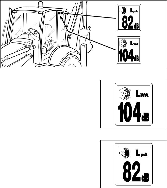
SAFETY, NOISE AND VIBRATION PLATES
2.1.4POSITION OF THE NOISE PLATES ON MACHINES WITH CAB (model WB93R-2)
•The noise plates must always be legible and in good conditions; for this reason, if they are dirty with dust, oil or grease, it is necessary to clean them with a solution made of water and detergent.
Do not use fuel, petrol or solvents.
•If the plates are damaged, ask for new ones to Komatsu Utility or to your Komatsu Utility Dealer.
•In case of replacement of a component provided with a noise plate, make sure that this plate is applied also on the new piece.
|
ISO 6396 |
|
2000/14/EC |
|
RWA37710 |
EXTERNAL NOISE
• This value indicates the noise level outside the machine and refers to the noise perceived by persons in the vicinity of the work area.
2000/14/EC
RWA37720
NOISE PERCEIVED BY THE OPERATOR
• This value indicates the maximum noise level perceived by the operator’s ears.
ISO 6396
RWA37730
27
SAFETY, NOISE AND VIBRATION PLATES
2.1.5 VIBRATIONS TO WHICH THE OPERATOR IS SUBJECTED
•According to the results of the tests carried out to determine the vibrations transmitted to the operator by the machine, the upper limbs are subjected to vibrations lower than 2.5 m/sq.sec., while the seated part of the body is subject to vibrations lower than 0.5 m/sq.sec.
28
![]()
GENERAL PRECAUTIONS
2.2 GENERAL PRECAUTIONS
2.2.1 GENERAL SAFETY RULES
•Only trained and authorized personnel can use the machine and perform maintenance operations.
•Follow all the safety rules, precautions and instructions when using the machine or performing maintenance operations.
•When working with other operators or when the work site is often occupied by other operators, make sure that everyone knows and understands all the signals described above and, in any case, that everyone works in such a way as to be able to see the machine and to be visible to the operator.
2.2.2 SAFETY DEVICES AND GUARDS
•Make sure that all the guards and covers are in the correct position. Have guards and covers changed or repaired if damaged. Neither use the machine without guards, nor remove the guards when the engine is running.
•Always use the proper safety devices to lock the machine when parking and fasten the safety belt.
•For the safety devices, see “3.1 SAFETY LOCKS”.
•For the safety belt, see “3.5.7 SAFETY BELT”.
•Do not remove the safety devices and always keep them in good operating conditions.
•Any improper use of the safety devices may result in serious injuries or even death.
2.2.3 CLOTHING AND PERSONAL PROTECTION ITEMS
•Do not wear large or loose clothes, rings and watches and do not approach the machine with loose long hair, since they can get entagled in the moving parts of the machine and cause se-
rious injuries or damage.
Avoid also wearing clothes dirty with oil or fuel, since they are flammable.
•Wear a hard hat, goggles, safety shoes, mask, gloves and headphones when operating the machine or performing main-
tenance operations.
• Always wear safety goggles, a hard hat and heavy gloves if your job involves scattering metal chips or minute materials; these precautions are particularly useful when driving the equipment connection pins with a hammer and when blowing compressed air into the air filter and the radiator to clean them. During these operations, make also sure that no one is standing or working near the machine without the necessary protections.
•When working for 8 hours with a noise level exceeding 90 dBA, it is necessary to use headphones or ear plugs and be
RWA00960
particularly careful, especially at the end of the work shift.
29

GENERAL PRECAUTIONS
2.2.4 UNAUTHORIZED MODIFICATIONS
•Any modification made without the authorization of Komatsu Utility can involve hazards.
•Before making a modification, consult your Komatsu Utility Dealer. Komatsu Utility declines any responsibility for injuries or damage caused by unauthorized modifications.
2.2.5 LEAVING THE OPERATOR’S SEAT
•When leaving the operator’s seat, even if temporarily, make sure that the machine is in a safe position. (See “2.4.11 PARKING THE MACHINE”).
•Before leaving the operator’s seat, carry out the following operations in the sequence indicated below:
1 — Rest the equipment onto the ground.
2 — Connect the safety devices of the controls.
3 — Apply the parking brake.
4 — Shift the reversing gear lever to the neutral position. 5 — Stop the engine.
IMPORTANT
•If the machine is equipped with backhoe servo controls, before leaving the operator seat always engage the control locking safety device by pressing the relevant switch, see “3.3.6.2 MACHINE CONTROLS (Version with servo controls)”, pos. 27.
If you have to go so far away that you will not be able to see the machine, extract the ignition key.
30

2.2.6GETTING ON AND OFF THE MACHINE
•Do not jump on or off the machine, either when it is at rest and when it is moving.
•When getting on or off the machine, always use the handles and the safety ladders; get on and off the machine very carefully.
•Never hold or rest on the steering wheel or the gearshift lever.
•Either when getting on and when getting off the machine, always maintain three points of contact (holding or resting points), in order to avoid losing your balance and falling down.
•Tighten the handle and ladder connection screws if they are loose and clean the handles and steps if they are dirty with oil or grease. Carefully clean the cab floor if it is dirty with oil, grease, mud or rubble.
2.2.7CHECKING THE REAR-VIEW MIRRORS
•Make sure that the rear-view mirrors are clean and correcly positioned; they must allow the operator to see the rear of the machine with no need to move the chest with respect to the normal work position.
•If the rear-view mirrors should move or break during work, stop the machine immediately and fasten or change them.
•Working without checking the back of the machine is dangerous, since the machine may hit persons who are incautiously standing in the work area, fixed obstacles or manoeuvring vehicles.
2.2.8PREVENTING FIRES DUE TO FUEL AND OIL
Fuel, oil and some types of antifreeze can be easily ignited if they get in contact with a flame. Fuel is particularly flammable and therefore extremely hazardous.
•Keep any naked flame away from flammable fluids.
•Stop the engine and do not smoke when refuelling.
•Top up with fuel and oil only after stopping the engine and in
well ventilated areas.
RWA00970
• Top up with fuel and oil in a well delimited area and do not allow unauthorized persons to approach.
31

GENERAL PRECAUTIONS
•When refuelling, hold the fuel gun firmly and keep it constantly in contact with the filler until you have finished, in order to avoid sparks due to static electricity.
•After topping up, tighten the fuel and oil safety caps securely.
•Do not fill the tank completely, in order to leave room for the fuel to expand.
•In case some fuel is spilled, wipe it up immediately.
2.2.9 PREVENTING BURNS
•If the engine coolant, the engine oil and the hydraulic oil are hot, use heavy cloths and wear gloves, heavy clothing and safety goggles before carrying out any check or touching the hot parts.
•Before checking the coolant level, stop the engine and let the fluid cool down.
If a check is necessary due to the overheating of the engine, slowly loosen the radiator plug to release any residual pressure before removing it. The hot fluid that spurts out may cause serious burns.
•Before checking the engine oil and hydraulic circuit oil level, stop the engine and let the oil cool down. The hot oil that can be sprayed out of the tank may cause serious burns.
2.2.10PREVENTING DAMAGE DUE TO ASBESTOS POWDER
•Asbestos powder can be hazardous to your health if it is inhaled.
•If you handle materials containing asbestos fibers, keep to the instructions given below:
1— Do not use compressed air, but only aspirators to clean the machine and make sure that the room in which you are working is properly ventilated.
2— Use low-pressure water to keep down the dust when cleaning.
3— If there is danger that there may be asbestos powder in the air, operate the machine with the wind to your back whenever possible.
4— Even if the cab provides suitable protection, use an approved and homologated respirator.
5— The powder gathered during the cleaning operations must be dampened and put in a sealed and marked container, so that it can be safely disposed of according to the regulations in force.
RWA00980
RWA00990
RWA01000
RWA01010
32

2.2.11PREVENTING DAMAGE CAUSED BY THE WORK EQUIPMENT
•Do not stand within or approach the operating radius of the work equipment, even when the operator is on board the machine and the engine is running.
•Do not stand or work under the arms or the articulations when the arms are lifted, if you are not sure that the safety locks have been duly engaged.
•Do not carry out any operation requiring the lifting of the arms, if you are not sure that the locks are correctly positioned and coupled to the arms.
GENERAL PRECAUTIONS
RWA01020
2.2.12FIRE EXTINGUISHERS AND FIRST AID KIT
•Make sure that fire extinguishers have been provided and check their position.
•Periodically make sure that the fire extinguishers are loaded and that you know how to use them.
|
• |
Find out where the first aid kit has been located. |
||||
|
• |
Periodically make sure that the first aid kit contains the neces- |
||||
|
sary disinfectants, bandages, medicins, etc. |
|||||
|
• |
It is necessary to know what to do in case of fire. |
RWA01030 |
|||
|
• |
Make sure that you have the phone numbers of the persons or |
||||
|
structures you may need to contact in case of an emergency |
|||||
|
at hand (either at the work site and where maintenance opera- |
|||||
|
tions are performed). |
2.2.13 PRECAUTIONS CONCERNING THE CAB STRUCTURE
• If the cab is inadvertently hit or the machine overturns during work, the cab may be damaged with consequent reduction of its stiffness and of the safety that must be guaranteed to the operator (Rops/Fops homologation). Contact Komatsu Utility or an Authorized Komatsu Utility Dealer to have the cab structure and resistance checked in case of impact or damage.
2.2.14 PRECAUTIONS CONCERNING THE EQUIPMENT
•When installing and using optional equipment, carefully read the relevant instruction manual and keep to the indications given therein.
•Do not use optional or special equipment without the authorization of Komatsu Utility or the Komatsu Utility Dealer.
The installation and use of unauthorized equipment may create safety problems and adversely affect the efficiency and life of the machine.
•Komatsu Utility cannot be held liable for any injury, accident, product failure resulting from the installation and use of unauthorized equipment.
33

PRECAUTIONS TO BE TAKEN BEFORE STARTING THE ENGINE
2.3PRECAUTIONS TO BE TAKEN BEFORE STARTING THE ENGINE
2.3.1 SAFETY ON THE WORK SITE
•Before starting the engine, thoroughly check the area for any unusual condition of the ground due to which work may be dangerous.
•Check the conditions of the ground at the work site and before
starting the engine define the work plan and the best and safest operating procedure.
• Make the ground surface as level as possible before carrying out any operation.
• In case of work on the road, protect pedestrians and cars by designating a person for work site traffic duty and install fences around the work site.
|
• If water lines, gas lines, and telephone or high-voltage electri- |
|
|
cal lines are located under the work site, contact the relevant |
|
|
utility company in order to find out their exact positions or to |
|
|
make them inneffective until the end of the operations. Be |
|
|
careful not to sever or damage any of these lines. |
RWA00220 |
•Check the depth and flow of water before operating in water or on river banks.
2.3.2 FIRE PREVENTION
•Completely remove all wood chips, rubbish, paper and other flammable materials that may have accumulated inside the engine compartment, since they can cause fires.
•Check the fuel and hydraulic system pipes for leaks and if necessary repair them. Wipe up any excess oil, fuel or other flammable fluids.
•Make sure that fire extinguishers are available in the work area.
RWA01040
2.3.3 PRECAUTIONS TO BE TAKEN FOR THE OPERATOR’S CAB
•Do not leave objects or tools lying around in the operator’s cab. They may hinder the operation of the brakes and cause serious accidents.
•Keep the cab floor and the controls (steering wheel and levers) clean, by removing any trace of oil and grease and, as far as the floor is concerned, remove any excess dirt (earth, stones, etc.).
•Check the safety belt and change it if it is broken or damaged. Replace any component only with homologated parts available at Komatsu Utility or its Dealers.
•Make always sure that the lock of the right door, which is considered the emergency door, is open.
34

PRECAUTIONS TO BE TAKEN BEFORE STARTING THE ENGINE
2.3.4 ROOM VENTILATION
• Before starting the machine in confined or poorly ventilated places, provide for proper ventilation or connect the engine exhaust pipe to a suction duct. The engine exhaust gases can be deadly.
RWA01050
2.3.5CLEANING WINDOWS, MIRRORS AND LIGHTS — CHECKING THE WINDSHIELD WIPER BLADES AND THE BULBS
•Remove any trace of dirt from the cab windows, lights and rear-view mirrors, in order to ensure perfect visibility.
•Adjust the rear-view mirrors if they have moved, so that the operator sitting in the driving position can clearly see the back of the machine.
If any window, light or mirror is damaged, change it.
•Make sure that the road lights, stoplights, direction indicators and working lights are properly working. If necessary, change the faulty bulbs with new ones, making sure that their power is correct.
•Check the conditions of the windshield wiper blades; the scraping wire must be smooth, with no indentations and attached to the rubber back of the blade.
In case of doubts on the efficiency of the scraping wire, change the blades.
35

PRECAUTIONS TO BE TAKEN WHEN WORKING
2.4 PRECAUTIONS TO BE TAKEN WHEN WORKING
2.4.1 STARTING THE ENGINE
•Before getting on the machine, walk around it and check for people and objects that might be in the way.
•Do not start the engine if warning plates have been attached to the steering wheel or the control levers.
•When starting the engine, sound the horn as an alert signal.
•Start the engine and operate the machine only while seated with fastened safety belt.
•Do not allow anyone to get on the machine or enter the cab.
2.4.2 RULES FOR ROAD TRAVEL
•The machine is equipped with multifunction safety locks that must be used both for maintenance operations and road travel.
•When it is necessary to travel on roads, proceed as follows:
1— Position the safety lock of the front loader, so that the bucket is raised from the ground, thus ensuring better visibility and the stability of the machine.
2— Install the front bucket antirotation lock and secure it with the safety pins.
3— Install the teeth protection casing on the front bucket.
4— Raise the backhoe boom until engaging the safety coupling. The arm and bucket must in any case be completely folded.
5— The backhoe must be rotated and resting on the structure. This is the only position homologated for road travel in Italy.
6— For travelling with folded backhoe, the unit must be moved on its guide in such a way as to be positioned towards the road center, against the lock and with the bucket facing the road side.
7— Fasten the backhoe with the antirotation pin.
8— Connect the safety chains to prevent the accidental lowering of the stabilizers.
9— Engage the loader and backhoe control lever safety locks. For further information on their position, see “3.1 SAFETY LOCKS”.
IMPORTANT
•If the machine is equipped with backhoe servo controls, before travelling on roads always engage the control locking safety device by pressing the relevant switch, see “3.3.6.2 MACHINE CONTROLS (Version with servo controls)”, pos. 27.
•When it is necessary to travel on roads, the four-wheel drive must be disengaged and the brake pedals must be connected with the appropriate pin.
•When travelling on roads, keep to the rule of the road and operate the flashing light positioned on top of the cab.
•When travelling on roads, keep the working lights off.
IMPORTANT
•In any case, keep to the traffic rules in force.
36

PRECAUTIONS TO BE TAKEN WHEN WORKING
2.4.3CHECKS FOR TRAVELLING IN REVERSE
•When operating in areas that may be hazardous or have poor visibility, designate a person to direct the movements of the machine and traffic on the work site.
•Before moving the machine, sound the horn to warn the persons standing or working in the area.
•There are blind spots behind the machine, which cannot be seen through the rear-view mirrors and where someone may be standing.
It is necessary to make sure that there is no one behind the machine before travelling in reverse.
On request the machine may be equipped with an acoustic alarm (1) to be used in case of reversal. If the machine is equipped with this acoustic alarm (1), before any reversal make sure that it functions correctly.
See “3.3.6 pos. 1 REVERSING GEAR LEVER” to check the functionality of the alarm.
RWAB0630
2.4.4 MOVING THE MACHINE
•When moving the machine, position the front bucket at about 30÷40 cm from the ground; this position makes it possible to evaluate the space required for the movements more precisely and at the same time ensures the stability of the machine.
•If the front bucket control lever is to be used during travel, avoid moving it abruptly; sudden manoeuvres change the attitude of the machine and make driving difficult.
•When travelling on rough ground, keep the speed low and avoid sudden movements of the bucket arm.
•If the machine has to travel over an obstacle, keep the front equipment as close to the ground as possible and travel at low speed, in order not to strain the axles and tyres.
37

PRECAUTIONS TO BE TAKEN WHEN WORKING
2.4.5 WORKING ON SLOPES
•Operations on slopes and on river or lake banks with damp ground may result in the tipping over or slipping of the machine.
•Do not work with the bucket downward with respect to the tractor.
•On hills, banks or slopes, keep the bucket very close to the ground (20÷30 cm from the ground) and in case of emergency quickly lower it to the ground to help the machine stop.
•Do not change direction and avoid travelling obliquely when working on slopes. It is advisable to go down or up to a flat place to perform these operations.
•Do not travel on wet grass or thick layers of leaves: if the machine moves obliquely in these conditions, it may slipi.
•Before working on a slope, always check the efficiency of the brakes, engage a low gear and the four-wheel drive.
•Do not travel down slopes in neutral; you may lose control of the machine and cause serious injuries and even death.
•Avoid disengaging the gearshift with the push button positioned on the loader control lever.
•When travelling down a slope, engage a low gear, so that the braking action of the engine is used to hold the machine, with no need to strain the brakes.
•When the fuel level indicator reaches the red reserve area during work on a slope, immediately provide for refuelling; due to the inclination of the machine, the engine may suck in air and suddenly stop, which represents a grave risk for the safety of the operator and of the persons before the machine.
•If the engine should stop all of a sudden, immediately lower the bucket to the ground, brake and apply the parking brake.
|
RWA02240 |
|
CORRECT |
|
RWA02350 |
38
![]()
PRECAUTIONS TO BE TAKEN WHEN WORKING
2.4.6 PREVENTING ELECTROCUTION
• Digging operations near overhead electric lines are extremely dangerous and they may also cause death due to electrocution; for this reason, when working near overhead electrical lines always respect the minimum safety distances prescribed by the competent authorities and by the accident-prevention rules in force.
•As far as underground long-distance lines are concerned, the minimum distance depends on the covering of the ducts in
which the cables are laid.
|
• |
The basic safety precautions to be taken to prevent this risk |
RWA04900 |
|
are the following: |
1 — Wear shoes with thick rubber or leather soles.
2 — Request the aid of another person who can warn you if the machine gets too close to the electric line.
3 — Operate at low speed.
4 — Learn what is to be done first in case of electrocution.
5 — Keep the phone number of the electricity company and of the nearest first aid station at hand.
•If the work equipment gets accidentally entangled in the cables, the operator must not leave the cab until the electricity company has insulated the line.
•When carrying out this kind of operations, warn everyone standing in the work area to keep at the minimum distance prescribed from the machine and the work equipment.
•Ask the electricity company what are the voltage of the cables and the minimum safety distance in advance.

 DANGER
•The minimum distances from overhead lines can vary in the different countries, according to the climate and to the humidity percentage in the air.
Indicatively, the distances indicated in the table should be respected.
|
Cable voltage |
Min. safety |
|
distance |
|
|
1.0 kV (distribution line) |
5 m |
|
6.6 kV (2÷3 insulators) |
5.2 m |
|
33 kV (min. 3 insulators) |
5.5 m |
|
66 kV (min. 6 insulators) |
6 m |
|
154 kV (min. 10 insulators) |
8 m |
|
275 kV (min. 19 insulators) |
10 m |
39
PRECAUTIONS TO BE TAKEN WHEN WORKING
2.4.7 VISIBILITY
•Switch on the road or working lights as soon as visibility decreases.
•If visibility decreases due to mist, smoke or heavy rain, stop the machine in a safe position and wait for the weather to improve until visibility becomes acceptableità.
2.4.8 WORKING ON ICY OR SNOW-COVERED SURFACES
•If the ground is icy or covered with snow, the response of the machine to the movements of the steering wheel may not be precise.
To limit the risks deriving from reduced directionality, proceed as follows: 1 — Engage the four-wheel drive.
2 — Travel using the accelerator smoothly and gradually.
3 — Brake smoothly and only after having slowed down by using the engine deceleration as much as possible. 4 — Avoid any sudden braking, rapid acceleration and abrupt steering with reduced steering radius.
•If the machine is used to clear snow or as snowplough on roads (installing the specific optional equipment and even chains, if necessary), be careful to the road shoulders and to any object/obstacle buried in the snow (wayside posts, milestones, signs just above the asphalt, etc.).
2.4.9PREVENTING DAMAGE CAUSED BY THE WORK EQUIPMENT
•When working in tunnels, galleries, under electric cables or other ducts (air, telephone lines) and wherever the height is limited, proceed with the greatest care to prevent the bucket or arms and the backhoe bucket from causing any damage.
2.4.10 WORKING ON LOOSE GROUND
•Avoid operating the machine too close to the edge of cliffs, overhangs and deep ditches.
These areas may collapse, making the machine fall down or tip over and this could result in serious injuries or death.
Remember that after heavy rain or earthquakes these dangerous conditions usually get worse.
•The earth laid near ditches is loose and can easily collapse due to the weight or vibrations of the machine. Be extremely careful: always close the cab doors and fasten the safety belt.
40

PRECAUTIONS TO BE TAKEN WHEN WORKING
2.4.11 PARKING THE MACHINE
•Park the machine on firm and level ground. If this is not possible and it is necessary to park on a slope, position the machine with the front bucket directed downwards and carry out the following operations:
1— While keeping the machine stopped with the brakes, apply the parking brake.
2— Dump the front bucket to the unloading position and lower the arms until the teeth are driven into the ground.
3— Carry out the same operations with the backhoe bucket.
4— Stop the engine.
5— Put wedges or safety blocks under the front and rear wheels.
•Always rest the work equipment on the ground; if it is necessary to park with raised arms, make sure that the safety locks are engaged.
•Always engage the control lever safety locks.
IMPORTANT
•If the machine is equipped with backhoe servo controls, always engage the control locking safety device by pressing the relevant switch, see “3.3.6.2 MACHINE CONTROLS (Version with servo controls)”, pos. 27.
•When leaving the machine, apply the parking brake, make sure that the cab windows are closed, remove the ignition key and finally lock the doors.
•If it is necessary to park on public roads, provide for signalling the presence of the machine according to the local regulations in force (signalling fires, fences, road works ahead, alternated direction and direction signs, etc.).
41

TRANSPORTING THE MACHINE ON MOTOR VEHICLES
2.5 TRANSPORTING THE MACHINE ON MOTOR VEHICLES
2.5.1 LOADING AND UNLOADING
•Loading and unloading the machine on/from a motor vehicle always involves potential hazards. Proceed with extreme care.
•Perform loading and unloading on firm, level ground. Maintain a safety distance from the edges of ditches or from road sides.
•If the vehicles used have not been appositely equipped, put support blocks under the ramps, in order to avoid any bending.
•Always lock the wheels of the transporting vehicle with wedges.
•Always use ramps that are sufficiently wide and can support the weight of the machine. The longitudinal axes of the ramps must be parallel to each other and perpendicular to the loading side board and their distance must be suitable for the tread of the machine.
•Make sure that the ramps are securely positioned and fastened to the loading board and that they have the same length.
•Position the ramps with a maximum inclination of 15°.
•Make sure that the ramp surface is clean and there is no trace of grease, oil, soil and ice; remove dirt from the wheels before starting to load the machine on the vehicle.
•The machine must be loaded on the vehicle with the bucket directed forwards, that is, in the direction of advancement of the vehicle.
•Do not correct the trajectory of the machine on the ramps. If necessary, get down the ramps and start the operation again.
•After loading the machine, block its wheels with wedges and secure it with tie-downs or chains that prevent even any sideward shift (see “3.9 TRANSPORTING THE MACHINE ON MOTOR VEHICLES”).
|
Ramps |
|
|
Blocks |
|
|
Max.15˚ |
Blocks |
|
RWA00240 |
2.5.2 TRANSPORT

 CAUTION
•During transport, the machine must be secured to the vehicle with closed doors and windows.
•Define the route to be followed, taking in consideration the width, height and weight of the transport means and of the machine.
Make sure that the dimensions of the machine are compatible with the road and any gallery, subway, bridge, electric and telephone lines, etc.
•Keep to the regulations in force regarding the permissible width, height, weight of the machine and the transport speed.
42

2.6 BATTERY
2.6.1PREVENTING RISKS THAT MAY BE DUE TO THE BATTERY
•Electrolytic batteries contain sulphuric acid that can quickly burn the skin and corrode clothes making holes in the fabric. If you spill acid on yourself, immediately rinse the involved area with plenty of water.
•Battery acid may cause blindness if splashed into the eyes.
If acid gets accidentally into your eyes, flush them immediately with plenty of water and consult a doctor without delay.
•If you accidentally swallow some acid, drink a large quantity of water or milk, beaten egg white or vegetable oil and in any case antiacid substances like magnesia, bicarbonate, etc.;. call a doctor or a poisoning prevention center immediately.
•When handling batteries, always wear safety goggles.
•Batteries generate hydrogen. Hydrogen is highly explosive and can be easily ignited with small sparks or naked flames.
•Before working with batteries, stop the engine and remove the ignition key.
•Avoid short-circuiting the battery terminals through accidental contact with metal objects or tools or through the inversion of the terminals.
•Tighten the battery terminals securely. Loose terminals may generate sparks and even cause the explosion of the battery.
2.6.2STARTING WITH BOOSTER CABLES
•When starting the machine with booster cables, always wear safety goggles.
•When starting the engine by means of another machine, avoid any contact between the two machines.
•Be sure to connect the positive cable (+) first and then the negative or earth cable (-) when connecting the booster cables. Disconnect first the negative or earth (–) cable and then the positive cable (+) after the start.
•Connect the batteries in parallel: positive to positive and negative to negative.
•When connecting the earth cable to the frame of the machine to be started, operate as far as possible from the battery. (See «3.15.3 IF THE BATTERY IS DOWN»).
•Do not attempt to start the engine by causing a short-circuit with the terminals of the starter (see “2.8.14 PRECAUTIONS REGARDING THE STARTER”).
BATTERY
RWA01060
WRONG
RWA01080
RWA01180
RWA01190
43

PRECAUTIONS FOR THE REMOVAL
2.7 PRECAUTIONS FOR THE REMOVAL
•The draw hooks must be used only for the first aid and not for towing the machine.
•Before moving the machine, make sure that the gearshift lever is in neutral and disengage the four-wheel drive.
•Incorrect manoeuvres may result in serious injuries or even death.
•To move the machine, use properly dimensioned steel cables; do not use worn cables or cables with broken strands (A), twisted cables (B), deformed cables (C).
•During the removal, no one can be allowed to get near the machines or the cable.
•Do not get astride the cable.
•Remove the machine only as much as necessary to permit the required repairs.
•Do not remove the machine in any way other than that indicated in paragraph “3.15.1 HOW TO REMOVE THE MACHINE”.

 CAUTION
•The maximum applicable force for each draw hook is F = 6200 kg.
•Use cables having the same length and draw continuosly and constantly, without jerks.
•The drawing force must be parallel to the machine axis (advancement direction), in such a way as to avoid the application of sideward forces on the draw hooks.
RWA05380
44

2.8 PRECAUTIONS FOR MAINTENANCE
2.8.1 WARNING PLATES
•Before starting any maintenance operation, position the machine on firm and level ground, engage the safety locks of the equipment and of the controls, stop the engine and apply the parking brake.
•If another person starts the engine and operates the controls while the operator is providing for service, this may result in serious injuries or even death.
•To avoid these risks, always attach warning plates to the steering wheel, to the control levers and to the ignition key before performing any maintenance operation; if necessary, attach additional warning tags also around the machine and in particular on the cab door handles.
PRECAUTIONS FOR MAINTENANCE
DO NOT
START
ENGINE
RWA01210
2.8.2 TOOLS
•Use only the tools provided with the machine and high-quality tools suitable for the tasks to be performed.
•Do not use worn, damaged, low-quality tools or tools that are not suitable for the tasks to be performed, in order to avoid any personal injuryti.
•After use, always clean the tools carefully and put them in the appropriate compartment positioned inside the seat support. After use, carefully clean the tools and put them in the compartment obtained inside the seat support. If the operator plans to keep on the machine some tools whose dimensions exceed those of the compartment positioned under the seat, he can store them in an appropriate tool box positioned on the rear outer part of the cab. See “3.5.11 ADDITIONAL TOOL BOX (if provided).”
2.8.3 PERSONNEL
•Any maintenance operation must be carried out exclusively by authorized and duly trained personnel; specific and personal protection measures must be adopted when grinding, welding and when using sledges or heavy hammers.
•When assemblying the equipment or cylinder connection pins, use wooden, plastic or in any case not excessively hard tools to check the centering of the holes.
Do not use your fingers, since you run the risk of cutting them.
45

PRECAUTIONS FOR MAINTENANCE
2.8.4 EQUIPMENT
•The normal or special equipment that must be installed on the machine or that have been removed must be stored in safe places, preventing them from falling down. If they fall on someone, they can cause serious bodily harm.
•When assemblying or removing any equipment, make sure that the ropes and the lifting hook are in good conditions and properly dimensioned for the load to be lifted.
2.8.5 WORKING UNDER THE MACHINE
•Always lower the work equipment to the ground or in any case to their lowest position before performing service or repairs under the machine.
•Always lock the machine tyres securely.
•Do not work under the machine, if this is not sufficiently supported.
2.8.6 CLEANING THE MACHINE
•Spilled oil or grease, scattered tools or broken pieces are dangerous, because they may cause someone to slip or trip. Always keep the machine and the work site clean and tidy.
•To clean the machine, use a pressurized jet of warm water or steam and the appropriate detergents available on the market. Do not use gas oil, oil or solvents, since the former leave an oily coat that favours the sticking of dust, while the latter (even if weak) damage the painted surfaces and therefore facilitate rusting.
•While cleaning the machine, keep the pressurized jet at a minimum distance of approx. 60 cm in order not to damage the warning plates and the pictograms.
If the plates are damaged, request Komlatsu Utility or your Komlatsu Utility Dealer to send you spare plates and change them.
•Water into the electrical system provokes the oxidation of the contacts and may hinder the start of the machine or even make it start suddenly and abruptly. For this reason, never use water or steam jets to clean sensors, connectors or the inside of the operator’s cab.
RWA01320
RWA02520
RWA01330
46

PRECAUTIONS FOR MAINTENANCE
2.8.7USE OF THE ENGINE DURING MAINTENANCE OPERATIONS
•During maintenance operations, let the engine run only when it is absolutely necessary. If the engine must be running (for example, when checking the functionality of the alternator), it is advisable that someone remains seated in the driving position, so that the engine can be stopped whenever necessary.
•During maintenance operations with running engine, never move the control locking devices from the “lock” position or change the position of the gearshift lever.
Service personnel must not move any control lever.
IMPORTANT
•If the machine is equipped with backhoe servo controls, always engage the control locking safety device by pressing the relevant switch, see “3.3.6.2 MACHINE CONTROLS (Version with servo controls)”, pos. 27.
•When carrying out maintenance operations, do not touch the moving parts of the machine and avoid wearing large and loose clothes.
2.8.8PERIODICAL CHANGE OF THE PARTS THAT ARE CRITICAL FOR SAFETY
•Periodically change the following components, which are important for safety and fire prevention: Fuel supply system: fuel delivery and return pipes.
Hydraulic system: main delivery pipes of the hydraulic pump.
Hydraulic system: work circuit pipes from the distributor to the hydraulic cylinders. Safety belt
•Even if they seem to be in good conditions, these components must be periodically changed with new ones. In fact, these components tend to deteriorate over time.
•If one of these parts is defective, change or repair it even if the change interval has not elapsed yet. (See “4.6 PERIODICAL CHANGE OF THE COMPONENTS CONNECTED WITH SAFETY).
47

PRECAUTIONS FOR MAINTENANCE
2.8.9 STOP THE ENGINE BEFORE CARRYING OUT ANY MAINTENANCE OPERATION OR INSPECTION
• Stop the machine only on firm and level ground and stop the engine before carrying out any maintenance operation or inspection.
•If it is necessary to have the engine running during maintenance, engage the safety LOCKS of the equipment control levers, apply the parking brake and carry out any maintenance
|
operation with the help of another person; an operator must re- |
RWA02000 |
|
|
main on board and the words to be used during the operation |
||
|
must be agreed upon. |
IMPORTANT
• If the machine is equipped with backhoe servo controls, always engage the control locking safety device by pressing the relevant switch, see “3.3.6.2 MACHINE CONTROLS (Version with servo controls)”, pos. 27.
• The person who carries out the maintenance operation must be very careful not to touch any moving part of the engine.
48
 Loading…
Поиск товаров
Группа компании “RICHTONE” всегда готова предложить Вам запасные части для техники Komatsu в нашем каталоге.
Для того что бы СКАЧАТЬ данную инструкцию напишите нам на электронную почту rceshopmanuals@gmail.com
подождите загрузки книги
Часть 1
Обратная связь
Если не удалось найти инструкцию, то Вы можете заказать её на нашем сайте. Мы постараемся найти нужную Вам инструкцию в электронном виде и отправим ее по электронной почте.
Не стесняйтесь обращаться к нам, если у вас возникли вопросы или пожелания:
Email: Onlinemanuals@ya.ru
Мы в социальных сетях
Социальные сети давно стали неотъемлемой частью нашей жизни. Мы узнаем из них новости, общаемся с друзьями, участвуем в интерактивных клубах по интересам
ВКонтакте >
Что такое Onlinemanuals.ru?
Onlinemanuals.ru – это сайт, где собраны инструкции и руководства пользователя на все случаи жизни: для бытовой техники, для лекарственных препаратов, для автомобилей, по строительству и ремонту.
Для правообладателей >