Как использовать инструменты тестирования Modbus ModbusPoll и Modbus Slave
1. Введение
Modbus Poll: имитатор главного устройства Modbus, используемый для тестирования и отладки подчиненных устройств Modbus. Программа поддерживает ModbusRTU, ASCII, TCP / IP. Используется для помощи разработчикам в тестировании ведомых устройств Modbus или для тестирования и моделирования других протоколов Modbus. Он поддерживает несколько интерфейсов документов, то есть можно одновременно отслеживать несколько подчиненных устройств / полей данных. Каждое окно просто устанавливает идентификатор подчиненного устройства, функцию, адрес, размер и интервал опроса. Вы можете читать и писать регистры и катушки из любого окна. Если вы хотите изменить один регистр, просто дважды щелкните значение. Или вы можете изменить несколько значений регистров / катушек. Предоставляет несколько форматов данных, таких как числа с плавающей запятой, двойной точности, длинное целое число (можно обмениваться последовательностями байтов).
Modbus Slave: имитатор подчиненного устройства Modbus, который может имитировать 32 подчиненных устройства / поля адреса. Каждый интерфейс обеспечивает поддержку автоматизации OLE для отчетов EXCEL. В основном используется для имитации ведомых устройств Modbus, получения пакетов команд от главной станции и отправки пакетов данных обратно. Помогите разработчикам коммуникационного оборудования Modbus смоделировать и протестировать протокол связи Modbus для моделирования, тестирования и отладки коммуникационного оборудования Modbus. В 32 окнах можно моделировать до 32 подустройств Modbus. Пользовательский интерфейс такой же, как Modbus Poll, поддерживает функции 01, 02, 03, 04, 05, 06, 15, 16, 22 и 23, отслеживая последовательные данные.
Два, использование опроса Modbus
1), установка и регистрация:
После завершения установки вы увидите ярлык ModbusPoll на рабочем столе, дважды щелкните ярлык, чтобы открыть программное обеспечение, и интерфейс после открытия будет таким, как показано на рисунке ниже.

Нажмите «Соединение» -> «Подключиться», появится окно регистрации; откройте файл readme после распаковки сжатого пакета, скопируйте серийный номер ModbusPoll 5A5742575C5D10 и вставьте его в столбец регистрации окна регистрации, как показано на рисунке ниже. Щелкните ОК, чтобы завершить регистрацию.
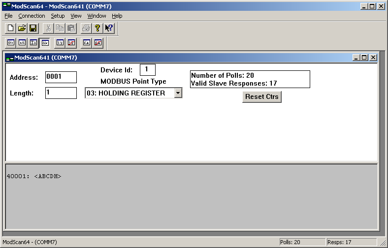
Введение в главное окно программы Modbus Poll 4.3.4
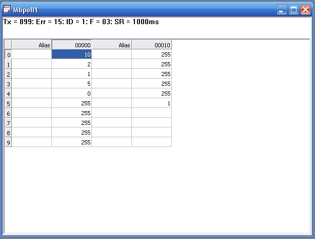
где: Tx = 4 означает количество кадров данных, отправленных на главную станцию, 4 раза на рисунке; Error = 0 означает количество ошибок связи, 0 раз на рисунке; ID = 1 означает аналоговый Адрес субустройства Modbus, адрес на рисунке 1; F = 03 означает используемый код функции Modbus, а цифра — код функции 03; SR = 1000 мс означает цикл сканирования. Красная часть указывает на текущее состояние ошибки, а «Нет соединения» указывает на неподключенное состояние.
3), настройки параметров:
Нажмите [Чтение / запись определения… F8] в меню [Настройка], чтобы установить параметры, и появится диалоговое окно настройки параметров.


Среди них: A. Slave — это адрес подчиненного устройства Modbus (подчиненного устройства), к которому необходимо получить доступ, соответствующий значению идентификатора в главном окне (главном экране), по умолчанию — 1. B. Функция — это выбор кодов функций регистра. Всего существует четыре типа, и соответствующие отношения следующие:
Код Название Регистр Адрес ПЛК Битовая операция / Словарная операция Количество операций
01 Состояние бита чтения / записи 00001-09999 бит, один или несколько
02 Чтение (ввод) бита 10001–19999 бит, один или несколько
03 Чтение / запись (сохранение) слова 40001–49999 слов, одно или несколько слов
04 Чтение (ввод) слов 30001–39999 слов, написанных одно или несколько
05 Запись одиночной катушки 00001-09999 бит одиночной
06 Запись одного регистра временного хранения 40001–49999 слово, слово, одно слово
15 Запись нескольких катушек 00001-09999 бит, кратный
16 Запись нескольких регистров хранения 40001–49999 слов, несколько слов
C. Адрес — это начальный адрес регистра, по умолчанию он начинается с 0.
D. Длина — это количество последовательных регистров, значение по умолчанию — 10, что соответствует количеству каналов программы настройки.
E. Скорость сканирования — это цикл чтения данных в миллисекундах, по умолчанию — 1000 мс.
После настройки нажмите кнопку ОК, и в окне моделирования отобразится определенный список регистров.
4), настройки отображения:
Настройка режима отображения данных:
По умолчанию режим отображения данных регистра — Подписанный (двоичный код с шестнадцатеричным знаком), а диапазон данных составляет -32768 ~ 32767. Если пользователь хочет отображать другие числовые способы, он может выбрать и установить через меню 【Display】, как показано на рисунке ниже:

Настройка формата адреса: Modbus Slave использует адрес ПЛК по умолчанию, [PLC Addresses (Base 1)] в меню [Display] выбран по умолчанию, а начальный адрес регистра по умолчанию равен 1, это Последовательный порт Modbus и драйвер пересылки данных TCP точки и конфигурационное программное обеспечение одинаковы. Если вам нужно установить начальный адрес, чтобы он начинался с 0 во время теста, вы можете выбрать [Адреса протокола (база 0)]. Как правило, достаточно адреса ПЛК по умолчанию.
Используйте кнопку «Коммуникационный трафик» на панели инструментов для отображения текущих отправленных команд и полученных данных.
5), подключение к последовательному порту:
Нажмите [Подключить … F3] в меню [Подключение], чтобы подключиться к последовательному порту, как показано ниже:

Среди них: Port3, что означает используемый последовательный порт (COM3), выбор другого последовательного порта или TCP / IP для подключения в зависимости от реальной ситуации. Режим означает режим протокола Modbus, действительный при использовании последовательного порта; при использовании TCP / IP это автоматически режим TCP. Время ожидания ответа означает время ожидания чтения.Если ведомое устройство не возвращает данные в течение времени ожидания, считается, что связь не удалась. Задержка между опросами, минимальный интервал времени для каждого сканирования, по умолчанию — 10 мс. Удаленный сервер означает сетевые настройки терминального ведомого устройства в режиме TCP / IP. IP-адрес, представляет собой IP-адрес подчиненной станции в режиме TCP / IP. Порт указывает сетевой порт подчиненной станции в режиме TCP. Пользователь может установить параметры в соответствии со своими потребностями, по умолчанию: последовательный порт 1, скорость передачи 9600, бит данных 8 бит, без бита четности, 1 стоповый бит. После подтверждения настроек нажмите кнопку ОК. Если он подключен и читается правильно, в главном окне будет отображаться информация о регистре чтения.
6), изменение значения регистра:
Дважды щелкните мышью по адресу регистра в главном окне, появится диалоговое окно изменения, как показано на рисунке ниже:

Введите значение в поле ввода «Значение» для подтверждения. Диапазон значений: -32768——32767.
Среди них: Slave — это адрес подчиненного устройства Modbus, к которому необходимо получить доступ, соответствующий значению идентификатора на главном экране, значение по умолчанию — 1. Адрес — это адрес текущего реестра. На рисунке показаны операции с регистром 40001. Использовать функцию — это используемый код функции.Вы можете выбрать код функции 06 или 16. для записи.
7), проверьте фрейм данных связи:
Щелкните [Связь …] в меню [Отображение] или нажмите кнопку [101] на панели инструментов, чтобы вызвать диалоговое окно с информацией о мониторинге фрейма данных для отправки и получения данных через последовательный порт «CommunicationTraffic» для Просматривайте и анализируйте отправленные и полученные фреймы данных. Как показано ниже:

Среди них: первые 6 битов — это порядковый номер кадра данных. Rx представляет полученный кадр данных. Tx представляет отправленный фрейм данных.
8), отключите:
Нажмите [Отключить F4], чтобы отключиться и завершить тест. В это время в главном окне отображается красный значок «Нет подключения», указывающий на отключенное состояние.
Три, использование ведомого устройства Modbus
1), установка и регистрация:
Установите программное обеспечение, после завершения установки дважды щелкните, чтобы запустить ярлык ModbusSlave.
Метод регистрации: нажмите «Соединение» -> «Подключиться», появится окно регистрации; откройте файл readme после распаковки сжатого пакета, скопируйте серийный номер ModbusPoll, вставьте его в столбец регистрации в окне регистрации, нажмите «ОК», Трещина полная. Установка и взлом ModbusSlave аналогичны ModbusPoll, поэтому я не буду повторять его здесь.
2), главное окно:
Главное окно программы показано ниже:

В настоящее время он находится в неподключенном состоянии «Нет соединения». Если вы проверяете только «Регистр удержания выхода 04», вы можете щелкнуть, чтобы перейти к шагу 3. и подключиться напрямую.
3), настройки параметров:
Нажмите «Определение ведомого … F2» в меню «Настройка», чтобы установить параметры, появится следующее диалоговое окно.

Среди них: A. Slave — это адрес ведомого устройства Modbus, соответствующий значению ID на главном экране, по умолчанию — 1.
B. Функция — это выбор кодов функций регистра, всего существует четыре типа, и соответствующие отношения следующие:
Код Название на китайском языке Зарегистрировать адрес ПЛК Битовая операция / Словесная операция Количество операций
01 Чтение статуса катушки 00001-09999 Битовая операция, одиночная или множественная
02 Чтение состояния дискретного входа 10001-19999 Битовая операция Один или несколько
03 Чтение регистра временного хранения 40001-49999 Операция Word Один или несколько
04 Чтение регистра ввода 30001-39999 Операция в виде слова Один или несколько
05 Запись одиночной катушки 00001-09999 Одинарная битовая операция
06 Запись одного регистра временного хранения 40001-49999 Одинарная операция Word
15 Запись нескольких катушек 00001-09999 Несколько битовых операций
16 Запись в несколько регистров хранения 40001–49999 Операция в несколько слов
C. Адрес — это начальный адрес регистра. По умолчанию начинается с 1.
D. Длина — это количество последовательных регистров. По умолчанию — 10.
Нажмите кнопку ОК, в окне моделирования отобразится определенный список регистров:

Среди них: ID представляет адрес устройства моделируемого субустройства Modbus; F представляет код функции.
Щелкните соответствующий регистр, чтобы изменить значение или статус соответствующего регистра. Например, значение регистра 2 изменяется на 9, а значение регистра 9 изменяется на 100.
4), настройки отображения:
Настройка режима отображения данных:
По умолчанию режим отображения данных регистра — Подписанный (шестнадцатеричный беззнаковый двоичный), а диапазон данных составляет -32768——32767. Если пользователь хочет отображать другие числовые способы, он может выбрать и установить через меню «Отображение», как показано на следующем рисунке:

Настройка формата адреса:
Modbus Slave по умолчанию использует адрес ПЛК. «Адреса ПЛК (база 1)» в меню «Дисплей» — это состояние, выбранное по умолчанию. Начальный адрес регистра по умолчанию — 1, что отличается от конфигурации. Программный последовательный порт Modbus и драйвер пересылки данных TCP одинаковы. Если вам нужно установить начальный адрес на 0 во время теста, вы можете выбрать «Адреса протокола (базовый 0)». Как правило, достаточно адреса ПЛК по умолчанию.
5), соединение:
Нажмите «Подключить … F3» в меню «Подключение», чтобы подключиться. Появится диалоговое окно подключения:

Где: Port2 означает используемый последовательный порт (COM2), выберите другой последовательный порт или TCP / IP для подключения в соответствии с реальной ситуацией.
Mode, что означает режим протокола Modbus, действителен при использовании последовательного порта; автоматически в режиме TCP при использовании TCP / IP
Управление потоком, что означает управление потоком, действительное в режиме последовательного порта;
Игнорировать идентификатор устройства, что означает, что недопустимые номера групп игнорируются в режиме TCP.
Пользователи могут установить параметры последовательного порта в соответствии со своими потребностями. Значение по умолчанию: последовательный порт 1, скорость передачи 9600 бод, 8 бит данных, без бита четности и 1 стоповый бит. После подтверждения настроек нажмите кнопку «ОК». В это время красный «Нет соединения» в главном окне указывает, что информация в неподключенном состоянии исчезает, указывая, что ведомое устройство находится в нормальном состоянии соединения.
6), изменение значения регистра:
Дважды щелкните мышью по адресу регистра в главном окне, появится диалоговое окно изменения, как показано на рисунке ниже:

Введите значение в поле ввода для подтверждения. Диапазон значений: -32768——32767.
Среди них: после того, как установлен флажок «Автоинкремент», значение соответствующего регистра может увеличиваться на 1 каждую 1 секунду.
7), проверьте фрейм данных связи:
Нажмите «Связь …» в меню «Дисплей», чтобы вызвать диалоговое окно с информацией о мониторинге фреймов данных отправки и получения последовательного порта для просмотра и анализа отправленных и полученных фреймов данных. Как показано ниже:

Среди них: первые 6 битов — это порядковый номер кадра данных.
Rx: представляет получаемый фрейм данных.
Tx: означает отправку кадра данных.
8), отключите:
Нажмите «Отключить F4», чтобы отключить и завершить тест. В это время в главном окне отображается красный значок «Нет подключения», указывающий на отключенное состояние.
Четыре, программа моделирования ведущего / ведомого устройства Modbus
1) Установите инструмент виртуального последовательного порта vspd. Добавьте два порта COM2 и COM3 через инструмент.

2) Затем откройте установленное программное обеспечение Modbuspoll и Modbus Slave и нажмите «F8», чтобы настроить соответствующую конфигурацию главного и подчиненного терминалов, как показано на рисунке:

В приведенной выше конфигурации идентификатор устройства 10 ведомых счетчиков равен 1, но считываются только данные первых 6 счетчиков, которые можно настроить в соответствии с вашей ситуацией.
2. Затем нажмите «F3» для подключения, обратите внимание на изменение порта интерфейса подключения, главная и подчиненная машины соответственно выбирают наши виртуальные порты com2 и com3, потому что я использую только RTU Mode, поэтому другие параметры, такие как скорость передачи 9600, бит 8, четность 1, без эквивалента и т. Д., Могут оставаться неизменными, а затем нажмите OK для подключения. Во второй строке неподключенного окна появится подсказка.
Когда начинается связь, на стороне хоста отображается: TX = 232, Err = 0, ID = 1, F = 03, SR = 1000 мс. Это означает, что нужно отправить 232 команды, время ошибки, ID ведомого, номер функции, интервал опроса.
Используйте кнопку «Коммуникационный трафик» на панели инструментов для отображения текущих отправленных команд и полученных данных.
Время на прочтение
10 мин
Количество просмотров 225K
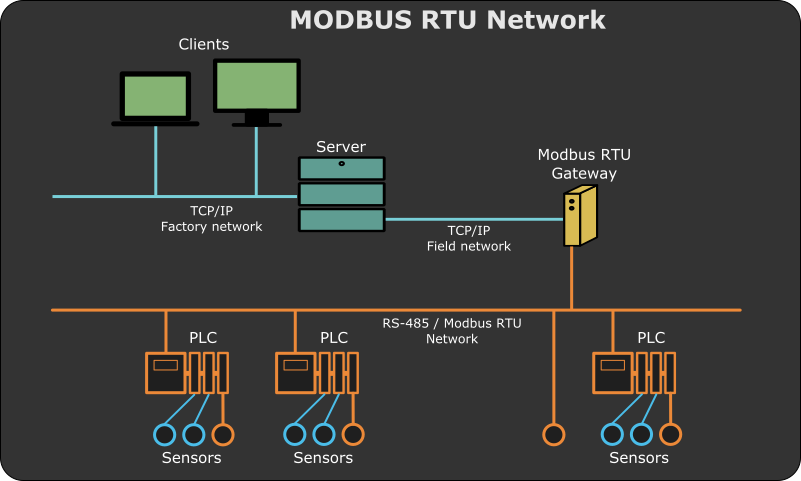
Протокол Modbus довольно распространен как в промышленных системах автоматизации, так и сетях систем типа «Умный дом», автоматизации малых объектов (теплицы и т.п.) и стыковки различного оборудования с домашним компьютером. Появление таких проектов как Arduino и Raspberry Pi значительно повысило интерес к задачам, связанным с робототехникой, автоматикой и автоматизацией. Все это обеспечивает рост популярности Modbus среди любителей и профессионалов. В статье рассмотрен вопрос тестирования и наладки, как отдельных устройств, так и сетей на базе протокола Modbus с позиции требований к программному обеспечению для решения таких задач и обзора существующих инструментов.
Если вы знакомы с архитектурой протокола, то можете смело пролистать пару следующих абзацев и перейти к дальнейшему описанию. Если же нет, то специально для вас ниже приведено небольшое введение в Modbus.
Modbus, краткое введение
Modbus является довольно распространённым протоколом в системах автоматизации на среднем и нижнем (полевом) уровнях. Средний — это уровень контроллеров — устройств, осуществляющих сбор данных и управление технологическим процессом. Нижний или полевой — это уровень взаимодействия датчиков и контроллеров или датчиков напрямую с сервером. Более подробно об уровнях в системах автоматизации можно посмотреть здесь.
Как правило, структура типовой системы автоматизации, использующей в качестве базового протокола Modbus, выглядит так как показано на рисунке в начале статьи. В качестве ”среды” для протокола Modbus может выступать либо RS-485/422/232 (подробно про RS-485 можно прочитать здесь и здесь), поверх него работает Modbus RTU или Modbus ASCII, либо транспортный протокол TCP в TCP/IP сетях, такая версия носит название Modbus TCP. В данной статье будет рассмотрен Modbus RTU.
Протокол Modbus предполагает наличие одного ведущего устройства в сети (оно называется Master или Client) и от 1 до 247 ведомых (они называются Slave или Server). Полное описание можно найти на официальном сайте или в вики.
Master периодически взаимодействует со Slave-устройствами, считывая или записывая в них какую-либо информацию. Этот процесс осуществляется в форме запрос-ответ. Запрос представляет собой последовательность байт, называемую кадром, в котором время между байтами стандартизировано и зависит от скорости передачи данных (напомним, что речь идет о Modbus RTU) и составляет не более длительности интервала, в течение которого может быть передано 1,5 байта данных. Время между кадрами должно быть не меньше времени передачи 3,5 байт.
Формат запроса имеет следующий вид:

ID — адрес устройства (1 байт),
FN — Modbus функция (1 байт),
[args] — аргументы функции (N байт, зависит от функции),
CRC — контрольная сумма CRC-16 (2 байта).
Ответ имеет схожий формат:

Почти все поля ответного кадра аналогичны кадру запроса, за исключением поля DATA, оно имеет различное наполнение, в зависимости от функции.
Если устройством не поддерживается запрашиваемая функция или аргументы в поле [args] запроса являются некорректными для данного Slave-устройства, то в ответе, в поле FN старший бит будет выставлен в 1 (т.е. на FN наложится маска 0x80), а в поле DATA будет помещена дополнительная информация об ошибке.
Каждое Slave-устройство может иметь определенные области данных и содержать дополнительную специфическую информацию.
Возможные области данных представлены в таблице ниже:
| Поле | Доступ | Размер | Описание |
|---|---|---|---|
| Discrete Inputs | Только чтение | Один бит | Данные от системы ввода/вывода |
| Coils | Чтение/Запись | Один бит | Ячейки могут использоваться по своему усмотрению |
| Input registers | Только чтение | 16 бит | Данные от системы ввода/вывода |
| Holding registers | Чтение/Запись | 16 бит | Регистры могут использоваться по своему усмотрению |
За более подробной информацией следует обратиться к полному описанию Modbus RTU, доступному в виде спецификации.
Тестирование устройств с поддержкой Modbus RTU в рамках процесса разработки
Как при разработке, так и при наладке устройств с поддержкой протокола Modbus RTU, вам необходимо иметь специализированное программное обеспечение и технические средства. Из технических средств наиболее простой вариант — это преобразователь RS-485/USB, из всех устройств такого типа, по нашему мнению, наилучшим выбором является MOXA UPORT 1130/UPORT 1150, цена вопроса которого составит 5000 — 6000 руб. Существуют различные отечественные решения, например, преобразователи фирмы Fractal или ОВЕН. Конструкция этих устройств достаточно проста, и при определенной сноровке такой преобразователь можно собрать самостоятельно. Более сложными являются решения типа Ethernet/RS-485 (например, NPORT от MOXA).
При разработке устройств с поддержкой Modbus RTU, чаще всего требуется реализовать функцию Slave, так как в основном это различные датчики, управляемые реле, модули ввода/вывода и т.п., Master-устройства создаются реже. В сетях автоматизации в качестве мастера, обычно выступает контроллер, а он, как правило, уже имеет реализацию Modbus-стека, либо OPC Server/SCADA система, укомплектованные Modbus-драйвером.
Вопрос разработки непосредственно Modbus-стека мы не будем рассматривать в этой статье. Единственное, стоит отметить библиотеку FreeMODBUS, на базе которой достаточно просто построить устройство с поддержкой функций Modbus Slave. Пример реализации описан в статье на Хабре.
Вторым важным моментом при разработке Modbus-устройств является тестирование. Здесь всё зависит от стадии разработки и цели тестирования.
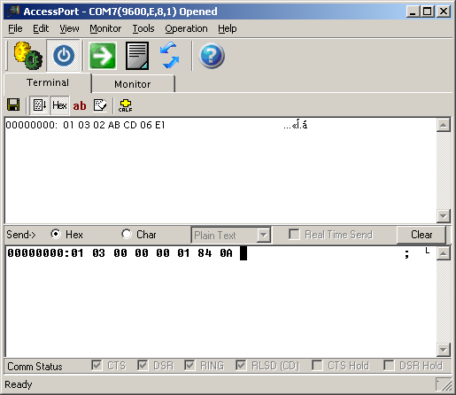
На начальных этапах полезным инструментом является Modbus-терминал. С помощью него мы можем вручную сконструировать запрос, послать его и проанализировать ответ. Существуют терминалы в чистом виде, например, SmartTerminal, Access Port, терминалы с поддержкой Modbus RTU — Termite от S2-Team или Pic18 Terminal от Fractal (не обновлялась с 2006 года) и т.п. Последний заточен под оборудование компании Fractal, но позволяет “общаться” с любыми устройствами, у которых в настойках порта выставлена четность None, с другими вариантами он не работает.
В процессе разработки нередко возникает ситуация, когда устройство принимает запрос и отвечает на него (это можно понять либо по светодиодам приема/передачи пакетов, если вы их предусмотрели в конструкции, либо через отладчик, поставив breakpoint в нужном месте), а в терминале или какой-то другой специализированной программе, данные не отображаются. В таком случае вам пригодится сниффер для последовательного порта, желательно, с поддержкой протокола Modbus. В качестве примера можно привести Free Serial Analyzer, COM Port Toolkit. Последний в настоящее время, похоже, прекратил свое развитие.
В дальнейшем, требуется не только проверять работает ли устройство в принципе (т.е. корректно отвечает на запросы), но и определять наработку на отказ с помощью длительного тестирования. Важными аспектами здесь являются поддержка авто-опроса с изменяемой нагрузкой (количество запросов в секунду) и наличие функции логирования. С этими задачами поможет справиться Modbus Poll или Modscan, это ПО платное, но имеется пробный период.
Следует учитывать, что собранные логи нужно будет анализировать, то есть определять количество запросов, на которые устройство не ответило, обнаруживать сбои, например, самопроизвольное изменение данных в ячейках и т.п. Конечно, можно использовать полноценную SCADA-систему, либо самому разработать и написать систему анализа и визуализации логов. Как вариант, рекомендуем обратить внимание на MasterSCADA от Insat. Она имеет встроенный Modbus-драйвер и версия до 32 точек является бесплатной, довольно проста в освоении (на сайте производителя есть хорошая документация и видео уроки).
В конце данной статьи мы определим список функций “идеального” инструмента для тестирования и наладки устройств/систем на базе протокола Modbus, а также сделаем небольшой обзор существующих инструментов.
Наладка систем автоматизации, использующих Modbus устройства
Людей, занимающихся наладкой систем автоматизации и просто пытающихся “подружиться” с каким-либо устройством, на борту которого находится Modbus, в разы больше чем, тех, кто эти устройства разрабатывает. Исходя из специфики задачи, требования к соответствующему ПО будут немного отличаться.
Если необходимо соединить контроллер и одиночное Slave-устройство, то прежде всего, нужно установить с ним связь с помощью преобразователя интерфейсов RS-485/USB, ПК и специализированного программного обеспечения либо терминала. В таком случае, логика работы и набор инструментов ничем не отличается от тех, что применяются при разработке Slave-устройства на стадии тестирования. На этом этапе не требуется длительное тестирование с последующим анализом большого количества лог-файлов.
В случае, когда у вас уже есть готовая сеть устройств, можно выделить следующие задачи:
- проверка работоспособности всех устройств в сети (опрос каждого устройства в отдельности и проверка корректности ответа);
- нагрузочное тестирование (опрос устройств в сети в течение длительного времени). Желательно сделать несколько экспериментов с различной частотой опроса, а после провести анализ собранных данных на наличие отказов, не ответов, порчи данных и т.п.
В этом случае, понадобится либо терминал с возможностью создания списка запросов, либо специализированный инструмент типа Modbus Poll, который позволяет опрашивать несколько устройств в рамках одного проекта.
Modbus-устройства могут иметь определенные настройки интерфейса RS-485: количество бит данных, четность и количество стоп бит. Устройства с различными настройками не могут работать в одной сети с одним и тем же мастером. Тестирование и конфигурирование таких устройств удобно проводить, применяя терминальные программы, имеющие возможность быстрого переключения между предустановленными профилями настроек портов или работающие с несколькими линиями одновременно.
Реже возникает задача организации обмена данными с устройством, протокол которого отличается от стандартной спецификации Modbus RTU. Нам приходилось встречаться с ситуацией, когда протокол Slave-устройства логически повторяет Modbus (структура пакета, таймауты и т.п.), но использует функции вне стандарта. В таком случаем возможна работа с использованием Modbus Poll, он позволяет строить произвольные запросы, или терминала, обладающего сходным функционалом. Стандартная SCADA-система, обычно, в такой ситуации бессильна, и работа с подобным оборудованием осуществляется через специальный OPC сервер.
Требования к ПО для работы с Modbus-устройствами в режиме мастера
Описав различные задачи, которые возникают при разработке, настройке и наладке устройств с протоколом Modbus, составим список требований к специализированному программному обеспечению.
- Поддержка настроек COM-порта (номер, скорость, четность, количество бит данных и стоп бит)
- Настройка таймаутов (время ожидания приема ответа на запрос, время между символами и кадрами)
- Поддержка стандартного Modbus
- Поддержка нестандартного Modbus
- Авто-опрос одного/нескольких устройств
- Настройка авто-опроса
- Логирование сессии / настройка логирования
- Создание профилей для быстрого переключения между настройками порта
- Работа в режиме сниффер
- Лицензия продукта
- Сопровождение продукта разработчиком
Обзор ПО для работы с Modbus протоколом
Modbus Poll
Начнем с классического приложения и довольно известного в наших “узких” кругах — Modbus Poll от Witte Software.

Эта программа является симулятором мастера в Modbus-сети. Интерфейс Modbus Poll интуитивно понятен. Если вы представляете себе логику работы протокола, то разобраться с программой труда не составит.
| Функция | Наличие | Комментарий |
|---|---|---|
| Поддержка настроек COM-порта | + | |
| Настройка таймаутов | + | Доступны: время ожидания ответа |
| Поддержка стандартного Modbus | + | Список функций ограничен |
| Поддержка нестандартного Modbus | + | |
| Авто-опрос одного / нескольких устройств | + / + | |
| Настройка авто-опроса | + | Доступно: время между запросами |
| Логирование сессии / настройка логирования | + / + | |
| Создание профилей для быстрого переключения между настройками порта | — | |
| Работа в режиме сниффер | — | |
| Лицензия продукта | ПО платное | Есть пробный период 30 дней |
| Сопровождение продукта | + |
Достоинства: хорошая система логирования, достаточное количество поддерживаемых функций (во всяком случае, наиболее востребованные присутствуют), большое количество настроек внешнего вида.
Недостатки: цена (одна лицензия $ 129.00), нестандартный Modbus поддерживается как опциональная функция, нет профилей для быстрого переключения портов — приходится каждый раз перенастраивать соединение.
Modscan32/64
Следующим ПО в нашем обзоре будет Modscan от WinTECH. Внешне эта программа очень похожа на Modbus Poll, но функционалом она обладает значительно меньшим.
У Modscan есть одна уникальная особенность для программ данного типа — это возможность создания форм (своего рода мнемосхем). Пока ее функционалу далеко до реальных SCADA-систем, но наличие такого бонуса радует. На сегодняшний день это достаточно скудный, по своим возможностям инструмент (имеется ввиду редактор форм), но будем надеяться, что со временем, разработчики доведут его до хорошего уровня.
| Функция | Наличие | Комментарий |
|---|---|---|
| Поддержка настроек COM-порта | + | |
| Настройка таймаутов | + | Доступны: время ожидания ответа |
| Поддержка стандартного Modbus | + | Список функций ограничен |
| Поддержка нестандартного Modbus | — | |
| Авто-опрос одного / нескольких устройств | + / + | |
| Настройка авто-опроса | + | Доступно: время между запросами |
| Логирование сессии / настройка логирования | + / — | |
| Создание профилей для быстрого переключения между настройками порта | — | |
| Работа в режиме сниффер | — | |
| Лицензия продукта | ПО платное | Есть пробный период |
| Сопровождение продукта | + |
Достоинства: возможность создания собственных форм для просмотра данных, поддержка MMI & OLE Automation.
Недостатки: цена (одна лицензия $ 84.95), нет поддержки нестандартного Modbus, нет профилей для быстрого переключения портов, ненастраиваемая система логирования, малое количество поддерживаемых Modbus-функций.
Termite
Следующим в нашем списке будет терминал Termite от S2-Team. Termite является специализированный Modbus терминалом. Это означает, что он сам будет считать за вас CRC, распознавать сообщения об ошибках в ответах и т.д., ваша задача заключается в том, чтобы ввести корректное тело запроса в поле команды.

| Функция | Наличие | Комментарий |
|---|---|---|
| Поддержка настроек COM-порта | + | |
| Настройка таймаутов | + | Доступны: время ожидания ответа, время между символами и кадрами |
| Поддержка стандартного Modbus | + | |
| Поддержка нестандартного Modbus | + | |
| Авто-опрос одного / нескольких устройств | + / + | |
| Настройка авто-опроса | + | Доступно: время между запросами |
| Логирование сессии / настройка логирования | + / — | |
| Создание профилей для быстрого переключения между настройками порта | + | |
| Работа в режиме сниффер | — | |
| Лицензия продукта | Есть платная и бесплатная версии |
Бесплатная версия обладает ограниченным функционалом (на количество каналов, одновременно ведомых лог файлов и количество разных запросов в авто-опросе) |
| Сопровождение продукта | + |
Достоинства: поддержка всех Modbus-функций, работа с нестандартным Modbus, удобная система подсказок, возможность настройки внешнего вида ПО, поддержка профилей для быстрого переключения между настройками порта.
Недостатки: PRO версия платная (одна лицензия $ 10), в текущем релизе нет возможности гибко настраивать логирование.
AccessPort
Программа из разряда “чистых” терминалов. Она не поддерживает Modbus, поэтому при её использовании будьте готовы считать CRC для ваших кадров самостоятельно. Несомненным плюсом является то, что в неё встроен сниффер последовательного порта.
| Функция | Наличие | Комментарий |
|---|---|---|
| Поддержка настроек COM-порта | + | |
| Настройка таймаутов | + | |
| Поддержка стандартного Modbus | — | |
| Поддержка нестандартного Modbus | — | |
| Авто-опрос одного / нескольких устройств | + / — | |
| Настройка авто-опроса | + | Доступно: время между запросами |
| Логирование сессии / настройка логирования | + / — | |
| Создание профилей для быстрого переключения между настройками порта | — | |
| Работа в режиме сниффер | + | |
| Лицензия продукта | ПО бесплатное | |
| Сопровождение продукта | Не поддерживается | Крайняя версия продукта была выпущена 2012-04-23 |
Достоинства: наличие сниффера порта, ПО бесплатное, настраиваемое представление данных, возможность передачи файлов.
Недостатки: не поддерживает Modbus вообще, нет возможность создавать профили, в режиме авто-опрос можно работать только с одним устройством, в настоящее время ПО не развивается.
В заключение хотелось бы добавить, что в сети достаточно большое количество программ для работы с последовательным портом, но если есть необходимость работать именно с Modbus протоколом, то его поддержка в таком ПО крайне желательна. Одна из основных причин — это расчет CRC, в ручную это делать накладно, также важно, чтобы программа могла уметь разделять кадры, иначе все превращается в сплошную мешанину байтов, ну и если есть авто-опрос, то это сильно упрощает жизнь.
Хочется дополнить список ПО и библиотек для работы с Modbus, тем, что было переставлено в комментариях.
SCADA
FreeSCADA
Modbus TCP/RTU
Advanced TCP/IP Data Logger
Ardsoft Эмулятор Modbus
PortMon
MODBUS FOR WINDOWS
PeakHMI
Modpoll Modbus Master Simulator
QModMaster
modbus_tk
pymodbus
libmodbus
Благодарю всех, кто помог улучшить статью!
Спасибо за внимание!

21 мая 2014
Не всегда с первого раза понятно как настроить наши модули с помощью программы «Modbus Poll» и в этой статье я расскажу как это сделать.
Саму программу можно скачать по следующему адресу — http://www.modbustools.com/modbus_poll.asp
Перед запуском программы подключите настраиваемый модуль к преобразователю USB-RS485, а сам преобразователь к компьютеру. В системе должен появиться новый последовательный порт (COM3, например). Подайте питание на модуль и запустите программу.
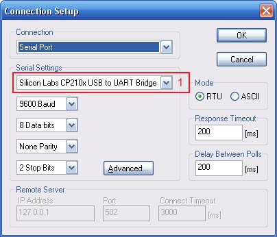
После запуска программы необходимо произвести настройку соединения, для этого выберете пункт меню «Connection→Connect», настройте соединение как показано на рисунке ниже, изменив только последовательный порт (1):
Для установки ModBus адреса устройства, выберете пункт меню «Functions→Write Single Register», появиться следующее окно, установите значения полей как показано ниже, изменив только поле (1), где укажите новый адрес устройства:
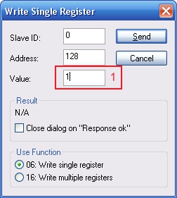
Нажмите кнопку «Send».
Небольшие пояснения: в данном случае мы послали широковещательную команду по шине (это определяется адресом устройства 0, поле Slave ID), на запись в параметры устройства, по смещению 0 (для датчиков MSU24R, MSU34R смещение 128), значения нового адреса устройства.
На широковещательные команды наши модули не отвечают, поэтому, попытка чтения с устройства с адресом 0, ни к чему не приведут!
Теперь необходимо перезапустить модуль, путем пере подключения питания.
После перезапуска модуля, можно настроить программу «ModBus Poll» для чтения данных с модуля.
Для чтения входных каналов, выберете пункт меню «Setup→Read/Write Definition»:
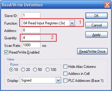
В поле (2) кол-во регистров может быть разное, для MSU44R — 4, а для DRM88R — 8.
Для просмотра настроек модуля, выберете пункт меню «Setup→Read/Write Definition»:
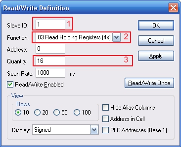
В результате настройки модуля отобразятся в следующем окне:

Witte Software Modbus Poll User manual Modbus Master Simulator
September 2012 Modbus Poll version 5.5 Copyright: Witte Software, 2002 -2012 http://www.modbustools.com

http://www.modbustools.com 2 Modbus Poll User manual
Table of content 1 Modbus Poll …………………………………………………………………………………………………………………………….. 4 2 Modbus Poll Features ……………………………………………………………………………………………………………….. 5
2.1 Connections ……………………………………………………………………………………………………………………… 5 2.2 Supported Modbus Functions …………………………………………………………………………………………….. 5 2.3 Data logging ……………………………………………………………………………………………………………………… 5 2.4 Display formats …………………………………………………………………………………………………………………. 5 2.5 Miscellaneous features ………………………………………………………………………………………………………. 5
3 Overview …………………………………………………………………………………………………………………………………. 6 3.1 Help from anywhere ………………………………………………………………………………………………………….. 6 3.2 Alias cells …………………………………………………………………………………………………………………………. 6 3.3 Value cells ………………………………………………………………………………………………………………………… 7 3.4 Change color and font ……………………………………………………………………………………………………….. 7 3.5 Open a new window ………………………………………………………………………………………………………….. 8
4 Connection dialog …………………………………………………………………………………………………………………….. 9 4.1 Connection……………………………………………………………………………………………………………………….. 9 4.2 Serial Settings …………………………………………………………………………………………………………………. 10 4.3 Mode …………………………………………………………………………………………………………………………….. 10 4.4 Response timeout ……………………………………………………………………………………………………………. 10 4.5 Min delay between polls ………………………………………………………………………………………………….. 10 4.6 Remote Server ………………………………………………………………………………………………………………… 10 4.7 Advanced settings……………………………………………………………………………………………………………. 10
4.7.1 RTS Toggle ……………………………………………………………………………………………………………….. 10 4.7.2 DSR …………………………………………………………………………………………………………………………. 10 4.7.3 CTS …………………………………………………………………………………………………………………………. 11 4.7.4 Remove Echo …………………………………………………………………………………………………………… 11
5 Read/Write definition ……………………………………………………………………………………………………………… 12 5.1 Slave ID ………………………………………………………………………………………………………………………….. 12 5.2 Function code …………………………………………………………………………………………………………………. 12
5.2.1 Read functions …………………………………………………………………………………………………………. 12 5.2.2 Write functions ………………………………………………………………………………………………………… 13
5.3 Address ………………………………………………………………………………………………………………………….. 13 5.3.1 Protocol/message address ………………………………………………………………………………………… 13 5.3.2 Device address …………………………………………………………………………………………………………. 13 5.3.3 5 digits vs. 6 digits addressing ……………………………………………………………………………………. 13
5.4 Address examples ……………………………………………………………………………………………………………. 13 5.4.1 Read Holding Registers ……………………………………………………………………………………………… 13 5.4.2 Read Discrete Inputs …………………………………………………………………………………………………. 13
5.5 Scan rate ………………………………………………………………………………………………………………………… 14 5.6 Read/Write Disabled ……………………………………………………………………………………………………….. 14
5.6.1 Disable on error ……………………………………………………………………………………………………….. 14 5.7 Hide alias columns …………………………………………………………………………………………………………… 14 5.8 Address in cell …………………………………………………………………………………………………………………. 14 5.9 PLC Addresses (Base 1) …………………………………………………………………………………………………….. 14 5.10 Rows ……………………………………………………………………………………………………………………………… 15
6 Display formats ………………………………………………………………………………………………………………………. 16 6.1 Native Modbus registers ………………………………………………………………………………………………….. 16 6.2 32 bit long ………………………………………………………………………………………………………………………. 16 6.3 32 bit floating …………………………………………………………………………………………………………………. 16 6.4 64 bit double …………………………………………………………………………………………………………………… 16
7 Save/Open Workspace ……………………………………………………………………………………………………………. 17 8 Test center …………………………………………………………………………………………………………………………….. 18

http://www.modbustools.com 3 Modbus Poll User manual
8.1 ASCII Example …………………………………………………………………………………………………………………. 18 8.2 TCP/IP Example ……………………………………………………………………………………………………………….. 18 8.3 Test center string file ……………………………………………………………………………………………………….. 18
8.3.1 Content of a string list ………………………………………………………………………………………………. 18 8.4 Copy ………………………………………………………………………………………………………………………………. 18
9 Modbus Data logging ………………………………………………………………………………………………………………. 19 9.1 Text file ………………………………………………………………………………………………………………………….. 19
9.1.1 Log Rate ………………………………………………………………………………………………………………….. 19 9.1.2 Delimiters ……………………………………………………………………………………………………………….. 19 9.1.3 Log if data changed only ……………………………………………………………………………………………. 19 9.1.4 Log Errors ………………………………………………………………………………………………………………… 19 9.1.5 Log Date ………………………………………………………………………………………………………………….. 20 9.1.6 Start Log when ok is pressed ……………………………………………………………………………………… 20 9.1.7 Start Log when *mbp is opened …………………………………………………………………………………. 20 9.1.8 Flush to file immediately …………………………………………………………………………………………… 20 9.1.9 Append …………………………………………………………………………………………………………………… 20
9.2 Microsoft Excel ……………………………………………………………………………………………………………….. 21 9.2.1 Log Rate ………………………………………………………………………………………………………………….. 21 9.2.2 Header information ………………………………………………………………………………………………….. 21
10 Communication traffic …………………………………………………………………………………………………………….. 23 11 OLE/Automation …………………………………………………………………………………………………………………….. 24
11.1 Excel example …………………………………………………………………………………………………………………. 24 11.1.1 Excel sample code…………………………………………………………………………………………………….. 24
11.2 Setup Functions ………………………………………………………………………………………………………………. 26 11.2.1 CreateRequest …………………………………………………………………………………………………………. 26 11.2.2 ShowWindow …………………………………………………………………………………………………………… 26 11.2.3 DisplayFormat ………………………………………………………………………………………………………….. 26 11.2.4 ReadResult ………………………………………………………………………………………………………………. 27 11.2.5 WriteResult ……………………………………………………………………………………………………………… 27
12 Exception and error messages …………………………………………………………………………………………………. 28 12.1 Modbus Exceptions …………………………………………………………………………………………………………. 28 12.2 Modbus Poll error messages …………………………………………………………………………………………….. 29

http://www.modbustools.com 4 Modbus Poll User manual
1 Modbus Poll
Modbus Poll is an easy to use Modbus master simulator developed for many purposes. Among others:
Designers of Modbus slave devices for quick and easy testing of protocol interface.
Automation engineers that need to test Modbus devices or networks on site.
Service engineers that want to read out and/or change specific service data from a device.
Change Modbus registers in a slave device.
Log data from Modbus devices.

http://www.modbustools.com 5 Modbus Poll User manual
2 Modbus Poll Features
2.1 Connections
Modbus Poll read/write data from devices using:
Modbus RTU or ASCII on a RS232 or RS485 network.
Modbus TCP/IP
Modbus Over TCP/IP. (Modbus RTU/ASCII encapsulated in a TCP packet)
Modbus UDP/IP
Modbus over UDP/IP. (Modbus RTU/ASCII encapsulated in a UDP packet)
2.2 Supported Modbus Functions
01: Read coils
02: Read discrete inputs
03: Read holding registers
04: Read input registers
05: Write single coil
06: Write single register
15: Write multiple coils
16: Write multiple registers
17: Report slave ID
22: Mask write register
23: Read/Write registers
2.3 Data logging
Log data to a text file
Log data direct into Excel
2.4 Display formats
Signed 16 bit register
Unsigned 16 bit register
Hex
Binary
32 bit long with any word/byte order
32 bit float with any word/byte order
64 bit double float with any word/byte order
2.5 Miscellaneous features
OLE/Automation for interfacing with Excel VB etc.
Monitoring of data traffic
Print and print preview
Font and color selection

http://www.modbustools.com 6 Modbus Poll User manual
3 Overview
Modbus Poll uses a multiple document interface. That means several windows can be opened. Each one with different data contents from different slave devices at the same time.
This picture shows two open windows. One reading 10 Holding registers from address 4000 (44001) and another reading 10 Holding registers from address 2000 (42001).
3.1 Help from anywhere
Press F1 and get context sensitive help on a topic associated with the current selected item. SHIFT + F1 invokes a special “help mode” in which the courser turns into a help courser (arrow + question mark). The user can then select a visible object in the user interface, such as a menu item, toolbar button, or window. This opens help on a topic that describes the selected item.
3.2 Alias cells
Here you can type any text for designation of the value cells. You can also copy/paste text from Excel cells.

http://www.modbustools.com 7 Modbus Poll User manual
3.3 Value cells
Show the data values of the Modbus registers. If you double click a value cell a dialog box lets you write a new value to the slave device. Typing a number in a value cell shows the dialog as well. It is possible to select the used Modbus function used to write the value. The check box “Close dialog on Response ok” is used to automatically close the dialog box when a value is successfully sent. This is convenient when a lot of values are to be changed. In that way it is fast to select a new cell and then type a new value again.
3.4 Change color and font
Select the cells to be changed and then right click. Then a context menu is shown with 3 options to change colors and font.

http://www.modbustools.com 8 Modbus Poll User manual
Colorize for better overview.
3.5 Open a new window
To open another window you have 3 options:
Press CTRL+N
Select new in the file menu
Press on the tool bar

http://www.modbustools.com 9 Modbus Poll User manual
4 Connection dialog
To open the connection dialog you have 2 options:
Press F3
Select connect from the connection menu
4.1 Connection
There are 5 different connection types:
1. Serial: Modbus over serial line. RS232 or RS485. A USB serial converter can be used.
2. Modbus TCP/IP: Select TCP/IP if you want to communicate with a MODBUS TCP/IP network. In this case, slave ID is the same as the Unit ID used in MODBUS TCP/IP. The port number is default 502. If the connection fails then try if you can ping your device at the command prompt. If the ping command fails then Modbus Poll fails too.
3. Modbus UDP/IP: Select UDP/IP if you want to communicate with a MODBUS UDP/IP network. This is the same as Modbus TCP/IP but the connection less UDP protocol is used instead.
4. Modbus RTU/ASCII over TCP/IP: This is a RTU or ASCII message send over a TCP/IP network instead of serial lines.
5. Modbus RTU/ASCII over UDP/IP: This is a RTU or ASCII message send over a UDP/IP network instead of serial lines.

http://www.modbustools.com 10 Modbus Poll User manual
Note: Connection type 3-5 is not standard Modbus as specified by www.modbus.org but they are
added for convenience.
Depending on your selection some other settings will be grayed.
4.2 Serial Settings
Use these parameters to set serial port settings. They are only available if connection type is “Serial Port”.
4.3 Mode
Use this option to select RTU or ASCII mode. Default RTU.
4.4 Response timeout
Response timeout specifies the length of time that Modbus Poll should wait for a response from a slave device before giving up. Default 1000ms.
4.5 Min delay between polls
This setting ensures a minimum delay until next request is transmitted no matter of the scan rate. Note: Setting this value to 0 uses quite a lot of processor recourses. The resolution of this setting is approximately 15ms. It’s possible on some computers to obtain better resolution but not all. Important: If you set this value lower than 20ms the 3.5 char time gap between response and a new request can’t be guaranteed. This is because the Windows scheduler switch tasks every 10 — 20ms.
1. If you Polls several slaves in a serial RS485 network you should NOT set the value lower than 20ms.
This is to ensure the 3.5 char time gap.
2. In a TCP/IP network. Less than 20ms is ok.
3. Serial connection to only one slave device. Less than 20ms is ok.
4.6 Remote Server
Remote server settings are only available when use an Ethernet connection.
IP Address: Servers IP address.
Port: Server port number. Default 502.
Connect Timeout: Max time to use to establish a connection. Default 1000.
4.7 Advanced settings
4.7.1 RTS Toggle
RTS Toggle specifies that the RTS line will be high if bytes are available for transmission. After all buffered bytes have been sent, the RTS line will be low. You can use this to switch direction if you have a RS232/485 converter without automatic direction switch.
Warning: The use of RTS controlled RS232/RS485 converters should be avoided if possible. It is difficult to determine the exact time when to switch off the transmitter with non real-time operating systems like Windows and Linux. If it is switched off to early characters might still sit in the FIFO or the transmit register of the UART and these characters will be lost. Hence the slave will not recognize the message. On the other hand if it is switched off too late then the slave’s message is corrupted and the master will not recognize the message.
4.7.2 DSR
DSR specify whether the DSR (data-set-ready) signal is monitored for output flow control. If this member is TRUE and DSR is turned off, output is suspended until DSR is sent again. Enable DTR handshaking

http://www.modbustools.com 11 Modbus Poll User manual
4.7.3 CTS
CTS specify whether the CTS (clear-to-send) signal is monitored for output flow control. If this checkbox is enabled and CTS is turned off, output is suspended until CTS is sent again. The DTR will be enabled whenever the port is opened and disabled when the port is closed.
4.7.4 Remove Echo
If your device or RS232/RS485 converter echoes the chars just sent.

http://www.modbustools.com 12 Modbus Poll User manual
5 Read/Write definition
Use this command to define the data to be monitored for the active window. To open the Read/Write Definition dialog you have 2 options:
Press F8
Select “Read/Write Definition” from the Setup menu
Press on the tool bar
5.1 Slave ID
Range 1 to 255. (MODBUS protocol specifications say 247 but some devices may use extended range 248 to 255). The value 0 is also accepted to communicate directly to a MODBUS/TCP or MODBUS/UDP device.
5.2 Function code
You can select 1 of 8 function codes
5.2.1 Read functions
The data returned by read functions are displayed on the grid window.
01: Read coils (0x)
02: Read discrete inputs (1x)
03: Read holding registers (4x)

http://www.modbustools.com 13 Modbus Poll User manual
04: Read input registers (3x)
5.2.2 Write functions
The write functions write the data displayed on the grid window.
05: Write single coil (Writes to Coil status)
06: Write single register (Writes to Holding registers)
15: Write multiple coils (Writes to Coils)
16: Write multiple registers (Writes to Holding registers)
5.3 Address
Addresses in the Modbus protocol are confusing! Some protocol specifications use the protocol/message address and other use device addressing.
5.3.1 Protocol/message address
Some protocol specifications use the protocol/message address counting from 0 to 65535 along with a function code. This is also what the new Modbus specifications use. This is the address inside the message sent on the wire. Modbus Poll use protocol/message address counting from 0 to 65535.
5.3.2 Device address
Some protocol specifications use device address/registers. Registers counts from 1. The first digit describes the function to be used. That means the device address 40101 is identified by address 100. The “4” means Holding registers and 4x registers counts from 1. And even more confusing: 4x means function code 03 and 3x means function code 04!
5.3.3 5 digits vs. 6 digits addressing
The address format 4x counts from 40001 to 49999. The next address is not 50000. In old days 9999 addresses was enough. There are cases where 9999 is not enough. Then a zero is added. 40101 become 400101 and so on. This is called 6 digits addressing or extended addressing. This is not a problem with Modbus Poll. 410001 become 10000. The “4” is thrown away and the rest 10001 is decremented by 1 as we count from 0 instead of 1.
5.4 Address examples
These examples show how to setup Modbus Poll if a specification use device addresses.
5.4.1 Read Holding Registers
You want to read 20 registers from device address 40011 from slave ID 2 every 1000ms. From the “4” we know this is function 03 “Read Holding Registers”.
— Slave ID = 2
— Function = ”03 Read Holding Registers (4x)”
— Address = 10 (11 minus 1)
— Quantity = 20
— Scan rate = 1000
5.4.2 Read Discrete Inputs
You want to read 1000 coils from address 110201 from slave ID 4 every 500ms. From the “1” we know this is function 02 “Read Discrete Inputs”
— Slave ID = 5

http://www.modbustools.com 14 Modbus Poll User manual
— Function = ”02 Read Discrete Inputs (1x)”
— Address = 10200 (10201 — 1)
— Quantity = 20
— Scan rate = 500
5.5 Scan rate
The scan rate can be set from 1 to 60000ms. Note that setting the scan rate lower than the transaction time does not make sense. If a serial connection at 9600baud is used and 125 registers are requested the transaction time is roughly 8 + 2 + 250 + 2 = 262ms + the gap (>3.5 char time) between the request and the response. In this case setting the scan rate at e.g. 100ms do not make sense as the transaction time is at least 262ms + delay in the slave (gap) + min time between polls. (Set in the connection dialog).
5.6 Read/Write Disabled
The ‘Read/Write Disabled’ check box can be used to temporary enable or disable the communication for this window. A text (Disabled) is then shown along with the Tx and Error counters.
If ‘Read/Write’ is disabled you can make single requests with the ‘Read/Write Once’ button or press F6.
5.6.1 Disable on error
The ‘Disable on error’ check box is used to disable Read/Write in case of error.
5.7 Hide alias columns
The ‘Hide Alias Columns’ is used to hide all alias columns. This is convenient to make more space if they are not used.
5.8 Address in cell
If enabled, the address is also shown in the value cell like: 2000 = 00000
5.9 PLC Addresses (Base 1)
This option will show the addresses as device address.

http://www.modbustools.com 15 Modbus Poll User manual
5.10 Rows
Specify the number of rows in the grid you prefer.

http://www.modbustools.com 16 Modbus Poll User manual
6 Display formats
Select one of the 16 display formats from the display menu.
6.1 Native Modbus registers
The 16 bit Modbus registers can be displayed in 4 different modes.
Signed.
Unsigned.
Hex.
Binary.
6.2 32 bit long
This combines 2 16bit Modbus registers. It can be displayed in 4 different word/byte orders.
Long AB CD
Long CD AB
Long BA DC
Long DC BA
Example: Byte Order: AB CD
The decimal number 123456789 or in hexadecimal 07 5B CD 15
Order as they come over the wire in a Modbus message: 07 5B CD 15
6.3 32 bit floating
This combines 2 16bit Modbus registers. It can be displayed in 4 different word/byte orders.
Float AB CD
Float CD AB
Float BA DC
Float DC BA
Example: Byte Order: AB CD
The floating point number 123456.00 or in hexadecimal 47 F1 20 00
Order as they come over the wire in a Modbus message: 47 F1 20 00
6.4 64 bit double
This combines 2 16bit Modbus registers. It can be displayed in 4 different word/byte orders.
Double AB CD EF GH
Double GH EF CD AB
Double BA DC FE HG
Double HG FE DC BA
Example: Byte Order: AB CD EF GH
The floating point number 123456789.00 or in hexadecimal 41 9D 6F 34 54 00 00 00
Order as they come over the wire in a Modbus message: 41 9D 6F 34 54 00 00 00

http://www.modbustools.com 17 Modbus Poll User manual
7 Save/Open Workspace
If you open many related Modbus windows it is convenient to save a snapshot of the current layout of all open and arranged Modbus Windows in one workspace. A workspace (*mbw) is just a file that contains display information and file names of all open windows. Not the actual contents. To do this, go to File-> Save Workspace. When you open a workspace file, Modbus Poll opens all Modbus Windows and displays them in the layout that you saved.

http://www.modbustools.com 18 Modbus Poll User manual
8 Test center
The purpose of this test dialog is to help MODBUS slave device developers to test the device with any string of their own composition. The list box displays the transmitted data as well as the received data. You can have several test strings in the pull down list box. When you have entered a string then press the «Add to List» button then the string is added to the list. The selected string is send when the «Send» button is pressed. With the «Save list» button you can store the strings in a text file. Check the «Add Check” check box if you want to add a CRC or LRC to the end of the input string. When using the test center you may want to disable communication from other windows. Check the “Read/Write disable” check box in “Read/Write Definition” dialog. Setup->Read/Write Definition.
8.1 ASCII Example
String in the combo box: 3A 30 31 30 33 30 30 30 30 30 30 30 41 The transmitted string if LRC is added 3A 30 31 30 33 30 30 30 30 30 30 30 41 46 32 0D 0A A CR LF pair are also added
8.2 TCP/IP Example
Read 10 holding registers. 00 00 00 00 00 06 01 03 00 00 00 0A First 6 bytes are the TCP/IP header.
8.3 Test center string file
With a text editor such as notepad or similar you can prepare strings to be used in the test. The first line in the file must be the string ‘Test Center’. This is how Modbus Poll knows that the file is the correct format. Press “Open list” to open the prepared text file.
8.3.1 Content of a string list
Modbus Poll
3A 30 31 30 33 30 30 30 30 30 30 30 41
3A 30 32 30 33 30 30 30 30 30 30 30 41
3A 30 33 30 33 30 30 30 30 30 30 30 41
8.4 Copy
Use the Copy button to copy selected Tx/Rx strings to the clipboard. The SHIFT and CTRL keys can be used together with the mouse to select and deselect strings, select groups of strings, and select non-adjacent strings.

http://www.modbustools.com 19 Modbus Poll User manual
9 Modbus Data logging
You can log data to either a text file or direct to Microsoft Excel.
9.1 Text file
Select Log from the setup menu or use short cut keys: Alt+L Each Modbus Window logs to its individual text file. When you want to stop the data logging then select the logging off command on the setup menu.
9.1.1 Log Rate
Each read: Write a log line for all Modbus requests. Log frequency as scan rate.
Select: Specify the log rate in seconds. Independent of scan rate.
Remark: If the scan rate is e.g. 10000ms it makes no sense to set a 1 sec log rate as data are logged
only when new data are ready.
9.1.2 Delimiters
As delimiter you can use one of following options:
Fixed width: Means that the values are organized in columns.
Comma: Values separated by a comma.
Tab: Values separated by a tab.
9.1.3 Log if data changed only
Specify that a new log line is written only if any data is changed since last log.
9.1.4 Log Errors
Specify that errors such a timeout etc. are logged.

http://www.modbustools.com 20 Modbus Poll User manual
9.1.5 Log Date
Specify that the current date is added to the log time.
9.1.6 Start Log when ok is pressed
Specify that logging is started when ok button is pressed. Otherwise the log setup is just stored when *mbp file is saved.
9.1.7 Start Log when *mbp is opened
Specify that logging is automatically started when a *.mbp file is opened.
9.1.8 Flush to file immediately
This ensures that log lines are not cashed in the file system but physical written immediately.
9.1.9 Append
Specify that logs are appended to selected file. Otherwise a new file is created. Example of a text file with fixed width:
22:28:13 <40001> 17395 0 0 0 0 0 0 0 0
22:28:14 <40001> 17396 1 0 0 0 0 0 0 0
22:28:15 <40001> 17394 1 0 0 2 55 0 0 0
22:28:16 <40001> 13350 1 0 0 4 0 0 0 0
You can import the data in an Excel spreadsheet.

http://www.modbustools.com 21 Modbus Poll User manual
9.2 Microsoft Excel
This feature requires that Microsoft Excel is installed. Excel log is limited to 65535 logs as this is the max number of rows in an Excel sheet. Each Modbus Window logs to its individual Excel sheet. Select Excel Log from the setup menu or use short cut keys: Alt+X Do not touch the Excel sheet while logging as this will interrupt the logging.
9.2.1 Log Rate
Each read: Write a log line for all Modbus requests. Log frequency as scan rate.
Select: Specify the log rate in seconds. Log is independent of scan rate.
Remark: If the scan rate is e.g. 10000ms it makes no sense to set a 1 sec log rate as data are logged
only when new data are ready.
Stop after: Specify the number of log lines
9.2.2 Header information
Insert header: Information is inserted in the top most 3 lines in the Excel sheet.
o Alias cells in top row: Insert alias names in row 3.
o Poll definition: Insert ID, Function etc. in row 2.
o Name: Insert a log name in row 1.

http://www.modbustools.com 22 Modbus Poll User manual
Excel log with header information.

http://www.modbustools.com 23 Modbus Poll User manual
10 Communication traffic
Select the menu Display->Communication to show the traffic on the serial line or Ethernet cable. Use the stop button to temporary stop the update for inspection. Use the copy button to copy selected line to the clipboard. Note: This window show only data sent and received by Modbus Poll. You can’t use it as a data sniffer. Hint: Leave this window open while doing other commands.

http://www.modbustools.com 24 Modbus Poll User manual
11 OLE/Automation
Automation (formerly known as OLE Automation) makes it possible for one application to manipulate objects implemented in another application. An Automation client is an application that can manipulate exposed objects belonging to another application. This is also called an Automation controller. An Automation server is an application that exposes programmable objects to other applications. Modbus Poll is an automation server. That means you can use any program that supports Automation such as Visual Basic, Excel etc. to interpret and show the MODBUS data according to your specific requirements. Hint: You should enable the auto connection in the connection menu in order to establish a connection when Modbus Poll is started by a client.
11.1 Excel example
You should display the Developer tab or run in developer mode when you want to write macros.
11.1.1 Excel 2007
1. Click the Microsoft office button and then click Excel options.
2. Click popular and then select the show Developers tab in the ribbon check box.
Note the ribbon is part of the Microsoft fluent user interface.
11.1.2 Excel 2010
1. Click on the file tab.
2. Click options. Excel Options window will open.
3. On the left pane click Customize Ribbon.
4. On the right pane, under Main Tabs, check the Developer check box.
5. Click OK. The Developer tab should now show in the ribbon (right most tab).
11.1.3 Excel sample code
This example is included with the Modbus Poll installation. Start -> All Programs -> Modbus Poll -> Examples Before you run this example make sure auto connect is enabled. Menu Connection -> Auto Connect -> Enable This example opens two windows. One reading registers and another reading Coils. Modbus Poll is hidden but you can show it by uncomment the “ShowWindow” line. This will show one of the windows.

http://www.modbustools.com 25 Modbus Poll User manual
Public m_svr1 As Object
Public m_svr2 As Object
Dim status As Integer
Dim Check As Boolean
Private Sub OpenModbusPoll_Click()
Set m_svr1 = CreateObject(«mbpoll.Document»)
Set m_svr2 = CreateObject(«mbpoll.Document»)
status = m_svr1.CreateRequest(1, 3, 0, 10, 1000) ‘ Read 10 Holding Registers
status = m_svr2.CreateRequest(1, 1, 9, 10, 1000) ‘ Read 10 Coils Status
‘Use this line if you want to show the window
‘status = m_svr1.ShowWindow
m_svr1.DisplayFormat = 0 ‘Format data as registers
Check = True
WriteValues.Enabled = True ‘Enable the buttons
WriteCoils.Enabled = True
End Sub
Private Sub Read_Click()
If Check Then
Cells(5, 7) = m_svr1.ReadResult ‘Show results for the requests
Cells(6, 7) = m_svr2.ReadResult
For n = 0 To 9
Cells(5 + n, 2) = m_svr1.Register(n)
Next n
For n = 0 To 9
Cells(18 + n, 2) = m_svr2.Coil(n)
Next n
Cells(7, 7) = m_svr1.WriteResult
End If
End Sub
Private Sub WriteCoils_Click()
For n = 0 To 9
m_svr2.Coil(n) = Cells(18 + n, 3)
Next n
status = m_svr2.ForceMultipleCoils(1, 9, 10)
End Sub
Private Sub WriteValues_Click()
For n = 0 To 9
m_svr1.Register(n) = Cells(5 + n, 3)
Next n
status = m_svr1.PresetMultipleRegisters(1, 0, 10)
End Sub

http://www.modbustools.com 26 Modbus Poll User manual
11.2 Setup Functions
11.2.1 CreateRequest
Function CreateRequest(SlaveID As Long,
Function As Long,
Address As Long,
Length As Long, ScanRate As Long) As Long
Return Value
True if success. False if not success
Parameters: SlaveID, The slave address 1 to 255. (247 is max according to MODBUS specification)
Function, 1, 2, 3 or 4
Address, The data address (Base 0)
Length, The number of data. 1 to 125 if registers. 1 to 2000 if coils
ScanRate, 20 to 60000ms
Remarks:
You must create a request before you can use properties to read
11.2.2 ShowWindow
Sub ShowWindow()
Call this function if you want the window to be shown in Modbus Poll. If ShowWindow is not
called the Modbus Poll window is not visible.
11.2.3 DisplayFormat
Specify the display format. Same formats as you find in the Display menu.
DisplayFormat As Long
Values
0 = DISPLAY SIGNED
1 = DISPLAY UNSIGNED
2 = DISPLAY HEX
3 = DISPLAY BINARY
4 = DISPLAY FLOAT CD AB
5 = DISPLAY FLOAT AB CD
6 = DISPLAY DOUBLE GH EF CD AB
7 = DISPLAY DOUBLE AB CD EF GH
8 = DISPLAY INT CD AB
9 = DISPLAY INT AB CD
10 = DISPLAY FLOAT DC BA
11 = DISPLAY FLOAT BA DC
12 = DISPLAY DOUBLE HG FE DC BA
13 = DISPLAY DOUBLE BA DC FE HG

http://www.modbustools.com 27 Modbus Poll User manual
14 = DISPLAY INT DC BA
15 = DISPLAY INT BA DC
11.2.4 ReadResult
Use this property to check if communication established with CreateRequest is running successful.
Property ReadResult As Integer
Return Value
0 = SUCCESS
1 = TIMEOUT ERROR
2 = CRC ERROR
3 = RESPONSE ERROR (The response was not the expected slave id, function or address)
4 = WRITE ERROR
5 = READ ERROR
6 = PORTNOTOPEN ERROR
10 = DATA UNINITIALIZED
11 = INSUFFICIENT BYTES RECEIVED
81h = ILLEGAL FUNCTION
82h = ILLEGAL DATA ADDRESS
83h = ILLEGAL DATA VALUE
84h = FAILURE IN ASSOCIATED DEVICE
85h = ACKNOWLEDGE
86h = BUSY, REJECTED MESSAGE
87h = NAK-NEGATIVE ACKNOWLEDGMENT
11.2.5 WriteResult
Returns a write result as integer. Use this function to check if a write was successful. The value is DATA_UNINITIALIZED until the result from the slave is available. See ReadResult for a list of possible values.
Property WriteResult As Integer

http://www.modbustools.com 28 Modbus Poll User manual
12 Exception and error messages
Modbus Exceptions and error messages are display in red text in 2nd line in each window.
12.1 Modbus Exceptions
Modbus exceptions are errors returned from the slave device.
Illegal Function The function code received in the query is not an allowable action for the server (or slave). This may be because the function code is only applicable to newer devices, and was not implemented in the unit selected. It could also indicate that the server (or slave) is in the wrong state to process a request of this type, for example because it is not configured and is being asked to return register values.
Illegal Data Address The data address received in the query is not an allowable address for the server (or slave). More specifically, the combination of reference number and transfer length is invalid. For a controller with 100 registers, a request with offset 96 and length 4 would succeeds, a request with offset 96 and length 5 will generate exception 02.
Illegal Data Value A value contained in the query data field is not an allowable value for server (or slave). This indicates a fault in the structure of the remainder of a complex request, such as that the implied length is incorrect. It specifically does NOT mean that a data item submitted for storage in a register has a value outside the expectation of the application program, since the MODBUS protocol is unaware of the significance of any particular value of any particular register.
Slave Device Failure An unrecoverable error occurred while the server (or slave) was attempting to perform the requested action.
Acknowledge Specialized use in conjunction with programming commands. The server (or slave) has accepted the request and is processing it, but a long duration of time will be required to do so. This response is returned to prevent a timeout error from occurring in the client (or master). The client (or master) can next issue a Poll Program Complete message to determine if processing is completed.
Slave Device Busy Specialized use in conjunction with programming commands. The server (or slave) is engaged in processing a long–duration program command. The client (or master) should retransmit the message later when the server (or slave) is free.

http://www.modbustools.com 29 Modbus Poll User manual
12.2 Modbus Poll error messages
Timeout error The response is not received within the expected time. Response Error The response is not the expected one. Different slave ID. CRC Error The CRC value of the received response is not correct. Write Error This is an error reported by the serial driver. This could happen if a USB/RS232/485
converter is used and the USB cable is unplugged. There are 4 types: — Break condition
— I/O error
— Serial connection error
— Output buffer overflow
Write error using TCP/IP connection is normally caused by lost connection.
Read Error This is an error reported by the serial driver. There are 6 types: — Framing error
— Character buffer overrun
— Parity error
— Input buffer overflow
— I/O error
— Break condition
Read error using TCP/IP connection is normally caused by lost connection.
Insufficient bytes received
The response is not the expected length
Byte count error The byte count in the response is not correct. Compared to the expected.
Modbus is a serial communication protocol because of its simple and easy to use, and there is no copyright requirements, which has become real-time standards for communication protocols in industrial fields. The Modbus protocol is Schneider Electric’s predecessor MoDicon proposed in 1979. Modbus currently has two major version of Modbus serial ports, Modbus TCP / IP, and MODBUS TCP / IP. There are two variants of Modbus serial port: Modbus RTU is a compact, mode of binary representation, Modbus ASCII is a human readable, lengthy expression. There is also an expansion protocol Modbus Plus (Modbus + or MB +), but this protocol is a high-speed token network proprietary to MoDicon, unlike modbus, it requires a special coprocessor to process high-speed tokens similar to HDLC . The following figure shows that the Modbus protocol specification and existing protocols are as seen from the figure that Modbus is based on an application protocol on an existing OSI network model.

Modbus protocol and ISO / OSI model specific situation

2, Modbus application scenario
The Modbus protocol can solve data acquisition problems of different types of devices in factories, so that we can monitor the operation of the factory at any time by collecting data. The Modbus protocol allows simple communication in a variety of network architectures, and its common architectural diagrams are as follows.

HMI represents the user-machine interface, PLC is a commonly used acquisition equipment commonly used in the factory, and the various PLCs, I / O data interfaces in the factory can collect its data through a variety of Modbus protocols, and different Modbus protocol networks can be passed The gateway performs data exchange.
3, Modbus Agreement Content Description
3.1 Modbus network form and protocol
First introduce what is transferred on the MODBUS network before introducing the Modbus network? Similar to other protocols, the most basic communication unit of the Modbus protocol is a frame, and the entire Modbus frame is also referred to as the application data unit (ADU), and the ADU includes a protocol data unit (PDU) for faxing data that is required to transmit.


The Modbus protocol is a protocol of a master / from architecture. Only one node is a master node in the same MODBUS network, and other nodes using the Modbus protocol participating in communication are from the (SLAVE) node, the maximum number of the node is 247. Each SLAVE device has a unique address. In serial and MB + networks, communication is always initiated by the master node (on Ethernet, any device can send a modbus command, but only one master node device start command), the child node is not received by the master node Data will not be sent when the request is requested. There will be no directly to each other between individual nodes.
At the same time, the main node will only initiate a Modbus transaction. What is transaction processing? In fact, it is a complete response communication on the network. Mainly includes two forms,1 unicast mode , 2 broadcast mode
The so-called unicast mode is that the primary node sends a message to a specified node (specified by the address domain in the ADU), after receiving and handling the request, returning a response message from the node to the primary node, in this mode Next, a Modbus transaction contains two packets, a request from the master node, a response from child node

So-calledBroadcast modeIt is the master node to send a request to all child nodes. When the address domain value of the request packet sent by the primary node is 0, all the slave nodes need to be processed, but do not need to return to the master node.

In fact, all devices in the physical layer will receive all requests, but when the address domain is not 0, the slave determines that the currently unicast mode, only the set of the address domain and its own address number will respond to the request, and the address domain is At 0, the slave determines that the broadcast message is broadcast, all the slave executes instructions, all devices that receive instructions run, but do not respond to the instructions.
There are two situations when the client (host) and server (slave) communications, one is normal, one is an abnormality.

The transaction is normal, and the client (host) sends a request to the server (slave) to the server (slave), fill the function code log in the function code, indicating the action required to perform, fill the specific requirements in the data code area, such as read registers. The address and quantity, the server will populate an operation code in the function code area of the returned communication frame, which is the same as the value of the data area of the communication frame in the function code area of the returned communication frame, fill the returned sampling data.

When the transaction is abnormal, the schematic is shown in the function code of the returned communication frame, the difference error code = function code + 0x80, the highest position 1 of the function code is an error. The wrong error is filled in the subsequent data segment to indicate the error specific content of this communication.

The error detection domain is a detection domain for communication links, whether or not an error occurs during the error check method such as a CRC (cyclic redundancy check code).
4, frame detailed
The three forms of communication of the Modbus protocol have different frames, and the specific

MBAP is a universal newsletter, depending on the reliable network layer, typical length of each domain is as follows (as an example of serial link)

Each functional domain:
4.1, address domain
The first part is that 8 bits are address domains, used to give the slave, and the host is not addressed, the server’s address must be unique. The Modbus address domain uses 1 byte, and the addressing space has 256 different addresses, but the legal address is 0 — 247.

The primary node is addressed by the address domain of the sub-node to the address domain of the packet. When the child node returns an answer, it puts his address in the address domain of the answer packet to let the master node know which child is answering.
4.2, function code
The second part 8 is a function code, and the function code indicates the action to be performed.
The host uses different functional code in the PDU, notifying the slave (server) to perform different actions, and the function code is divided into three categories:
A, public function code: This is the function code defined by the Modbus protocol organization, which is unanimously recognized, and it will not change in ordinary cases.
B, user-defined function code: There are two user-defined definition scope, decimal 65 to 72 and decimal 100 to 110, and can be used by the user.
C, reserved function code: This is some company’s function code used by some historical products, which is invalid for the public.

The definition of public function code is as follows:

Access form has single bits accesses and 16-bit access, there are file record access, where the coil here can be understood as switches 0, 1
4.3, data area
Before introducing the data area, first introduce the data model of the Mobbus protocol, and the data that Modbus accessible is stored in four blocks or address range: coil state , Discrete input, hold registers and input registers. The blocks here are conceptual definitions that they may exist as a separate memory address in a given system, but may also overlap. This is fully managed by the device.

Each block definition can contain 65,536 address spaces. In the definition of the PDU, Modbus defines the address of each data element, ranging from 0 to 65, 535. However, our physical devices such as registers, the coil usually numbered from 1 to N, where N is 65, 536. That is, the coil 1 1 is located in the coil state block of the address 10, and the holding register 34 is located in the slave is defined as a maintenance. Address 33 in the memory section of the register. When actual use, the device does not directly describe the data in a certain register, such as the voltage amount in the Save Register, but will be described as the voltage amount at address 40001 (or 4001, 40001, etc.), 4xxx, 4xxxx The difference between 4xxxxx depends on the address space used by the device. If all 65,536 registers are in use, 4xxxxx symbols should be used because they allow the beginning of the number of 400, 001 ~ 465, 536.4 because of the actual use of address encoding The prefix usually reflects the type of data, which is generally defined as follows, and the data type and prefix relationship.

4.4, error inspection domain
This domain is a serial link to perform the calculation results of the «redundant check» in the message content. Two different calculation methods are used in accordance with different transmission modes (RTU or ASCII).
4.5, the example
Request to read discrete output 20-38 instance

The state of the output 27-20 is represented as a hexadecimal value CD, or binary 1100 1101. Output 27 is the MSB of this byte, and output 20 is LSB. According to convention, the bit in one byte is represented as an MSB located on the left, and the LSB is located on the right. The output of the first byte is from left to right of 27 to 20. The output of the next byte is from left to right of 35 to 28. When serial transmission bits, the MSB is transmitted from the LSB: 20………………….. In the final data byte, output states 38-36 are represented as hexadecimal value 05, or binary 0000 0101. The output 38 is the sixth bit position on the left, and the output 36 is the LSB of this byte. Filled five remaining high bits with zero. If the number of outputs returned is not eight times, the remaining bits in the final data byte will be filled with zero. The internal process is as follows

4.6 exception code

5, about transmission
There are two kinds of serial transmission mode:RTU mode and ASCII mode
The transfer mode and serial parameters of all devices on the Modbus serial link must be the same. All devices must implement RTU mode, ASCII mode is a selection, and only devices configured to be the same mode can communicate with each other. On other networks (such as MAP, Modbus Plus) Modbus messages are converted to frames that are independent of serial transmission. Modbus uses «big-endian» represents address and data items. When sending multiple bytes, first send the highest significant bit. This is the byte level, and the BIT transmission mode is transmitted when transmitting each byte in the serial port line, and the LSB is sent first, and the MSB is sent.
RTU transmission mode

When the controller communicates in an RTU mode, each 8bit byte each 8bit bytes contains two 4bit hexadecimal characters. This way is a bit: at the same baud rate, more data can be transmitted than the ASCII mode.
Corresponding serial setting requirements
- 1 start bit
- 8 data bits, first send the minimum effective bit
- 1 bit as a parity
- 1 stop
Each character or byte is sent in this order (from left to right): the lowest effective bit (LSB)… Maximum Active Bit (MSB)


ASCII transmission mode
When the device of the Modbus serial link is configured to use ASCII (American Standard Code for Information
Interchange) When communicating, each 8-bit subterot in the packet is sent in two ASCII characters. When a communication link or device
This mode cannot be used in accordance with Timer Management of the RTU mode.
Note: This mode is lower than RTU efficiency due to two characters in one child.
Example: The sub-festival 0x5b will be encoded as two characters: 0x35 and 0x42 (ASCII encoding 0x35 = «5», 0x42 = «b»).
Corresponding serial port setting
- 1 start bit
- 7 data bits, first send the minimum effective bit
- 1 bit as a parity
- 1 stop
Each character or byte is sent in this order (from left to right): the minimum effective bit (LSB)… Maximum Active Bit (MSB).

(ASCII hex 3a) started with ‘Enter-change line’ (CR LF) pair (ASCII hex 0D and 0A).

6, Modbus Simulator Modbus Poll and Modbus Slave Introduction
Modbus Poll is a Modbus host emulator developed by Witte Software for testing and debuging Modbus slave devices. Software supports ModbusRTU, ASCII, TCP / IP protocol. Support multi-device monitoring, you can monitor multiple slave devices / data fields. Support graphical monitoring packet information, loop packet transmission, register value independent growth. You can graphically set the slave device ID, function, address, size, and polling interval. A variety of formats, such as floating point, double precision, long integer (can be exchanged), and support Excel export.
software download:
After opening the software, the main interface is as follows, and the red no connection indicates that no slave device is connected. The above line represents the current communication statistics, TX represents the number of transmit frames. Err represents the error frame. The ID represents the ID number of the slave, F represents the function code, the SR represents the polling period, and the IP address and port number are displayed in the lower right corner.

Click Connection-> Connect … Pop-up registration code input box, you can enter the registration code, no words click Regster Later to try 30 days

After entering the registration code, pop up the Connection configuration

Support 5 connection forms

1 serial: Through the serial line. RS232 or RS485. You can use a USB serial converter.
2 TCP/IP: If you want to communicate with TCP / IP network, select TCP / IP. In this case, the slave ID is the same as the unit ID used in TCP / IP. The port number defaults to 502. If the connection fails, it is attempt to ping the device at the command prompt. If the ping command fails, the polling will also fail.
3 UDP/IP: If you want to communicate with UDP / IP network, select UDP / IP. This is the same as TCP / IP, but the UDP protocol is used to connect.
The RTU / ASCII via TCP / IP: This is the RTU or ASCII message sent by the TCP / IP network instead of a serial line. RTU / ASCII via UDP / IP: This is the RTU or ASCII message sent by the UDP / IP network instead of a serial line. Connection Type 3-5 is nothttp://www.modbus.orgThe specified standard is for some special applications.
When the connection success consisher, the interface is as follows (you need to use the slave _ _ _ _ _ _ _

Serial connection configuration:
Select the serial port after selecting the serial port.

The serial configuration is generally the default, unless there is special requirements, the MODE can select the RTU and ASCII types. On the right side, you can set the response timeout, and the train interval. For the interval, it is typically set to 20ms, and if this value is set to less than 20 milliseconds, the time interval between the response and the new request is not guaranteed. This is because Windows process schedules switched once every 10 to 20 milliseconds. If multiple slaves are polled in the serial RS485 network, the value should not be set to less than 20ms. This is to ensure the time interval of 3.5 characters. In the TCP / IP network, it is possible to less than 20 milliseconds.
Click Advanced Advanced … you can see the advanced settings, here usually don’t need to take it here a little more
RTS switch: RTS Switch Specifies if byte can be used for transmission, the RTS line will be high. After sending all buffer bytes, the RTS line will become a low level. If your 232/485 converter is automatically switched in the automatic direction, you can use it to switch the direction. Try to avoid using RTS-controlled RS232 / RS485 converters. It is difficult to determine the exact time of the transmitter in a non-real-time operating system (such as Windows and Linux). If it is closed, the character may still be in the send register of the FIFO or UART, which will result in the data loss, but if the shutdown time is too late, the message of the slave will be destroyed, the master will not recognize the message.
DSR: DSR Specifies whether the DSR (Data Set Ready) signal is monitored for output flow control. If this member is True and the DSR is off, the output will be suspended until the DSR is sent again.
CTS: CTS Specifies whether to monitor the CTS (Clear Send) signal for output flow control. If this check box is enabled and the CTS is turned off, the output will be pause until the CTS is sent again.
DTR: DTR Specifies whether it is enabled or disabled when the port is turned on.
Delete echoIf you use the device or RS232 / RS485 converter to return to the characters just sent, enable this feature automatically delete echo.
TCP / IP connection protocol configuration

Similar to the serial configuration, just a server (slave) IP configuration, port number, network connection timeout setting, can also switch the IPv4 and IPv6 network protocols.
parameter settings
Click Setup-> Read / Write Definiton … You can set the content of the monitoring window monitoring.


After clicking, you can set the slave address, select the function code, such as 03 is the read hold register value, address to fill in the register address, here you should pay attention to the address address addressing method 40011-> 10, quantity fill in the number of registers to read
The View section is used to set the number of lines displayed, and the address display in the Cell is displayed. Modbus’s function code is defined as follows

Common function code and address corresponding table

Set the pseudonym, you can directly double-click the cell corresponding to the AliaS column filled with the name of the convenient memory.

Select Setup-> Excel Log … You can set an Excel log to facilitate data processing

Select Setup-> LOG … You can set the storage detail, storage rate, split, error record form, etc. of logs.

Test function:
MODBUS POLL provides convenient test assistance to directly select the corresponding function to send commands to the slave under the Function menu.

Modbus Poll also provides text sending adjustment work, click Functions-> Test Center … Enter the test center, you can directly click Send Send after editing the command.

display setting.
By default, MODBUS POLL displays data in linened, which can click the Display menu as needed to modify the display format of each cell as needed.

Select Communication … You can see communication frame information

Modbus Poll also provides a real-time drawing page to help users see data reception, in general, do not need, and observe communication frames directly when debugging is generally enough.

MODBUS SLAVE introduction
Mobus Slave is analoging from slave (servers) to assist primary stations development debugging. Open Modbus Slave to see the main interface

The ID in the figure is station number, f is the function code of the response host.
Set the connection to the connection-> connection setup before connecting to the host, here I chose the TCP / IP protocol, the serial protocol is similar

Configure the slave to click Slave Definition …, set it up click OK

Then make some settings for the emulation interface, you can fill in the name of the Easy recognition in the AliaS column, double-click the right cell to pop up the register editing window, you can fill in the value you need, check the Auto Increment can be automatically increased each other.

After configuring the Slave emulator, you can click Connection, then use the host connection, start simulation debugging


If you need serial port protocol debugging, you can use virtual serial tools
Software download address
Reference article:VSPD virtual serial tool — Since then, bid farewell to hardware serial debugging
7, Modbus emulator mod_rssim introduction
If it is just general debugging to see if there is data, and if Modbus Poll can consider MOD_RSSIM. MOD_RSSIM is a lightweight Modbus slave simulator that simulates the slave of ModbustCP and Modbusrtu, which can simulate 254 handled stations. The software is simple and convenient to meet the general host debugging.
Official website:www.adroit.co.z download link

Main program window
After opening the program, the simulation begins directly, and there can be a host to connect the emulator. The main interface of the software is as follows, very lightweight, most features can operate directly on the interface.

basic settings
First select the protocol type, you can select the protocol type at the PROT drop-down window.

Click on the serial port flag to set the port number and station number.


Green digital logo representative station number in the lower left corner

Address mode
The address supports HEX mode and DEC mode, which can be selected by address type, as follows, because we typically use 4001, 40001 and other addresses, it can generally select DEC decimal mode, address right side + 0, + 1, + 2 representative Offset, offset unit is set by FMT.

Data type selection
Modbus has four data models, and the software can be selected via the I / O drop-down window.

After selecting different data types, the addresses in Address will change.

Data length and modification
Click the FMT drop-down window to select the type of registration, the type there is a few, usually we use the 16bit register type, ie Word16.

Data manual settings, double-click the register address, you can fill in the required values.
MOD_RSSIM has a good function to simulate data automatic growth, which is convenient to observe data dynamic changes on the host side, (here you can’t set up a single register automatic growth) If you need this feature, you can use Modbus Poll, click on the red villain below.

Pop up the following window

You can choose Bytes growth. Words grows different types. You can fill in the increment on Inrement, such as the growth of +1, can also choose the growth interval. The site status can be set on the next half of the interface.
advanced settings
Click the advanced set icon

In the pop-up window we can set the number of data registers, PDU maximum lengths.
